WO2024034436A1 - Film intermédiaire pour verre feuilleté et verre feuilleté - Google Patents
Film intermédiaire pour verre feuilleté et verre feuilleté Download PDFInfo
- Publication number
- WO2024034436A1 WO2024034436A1 PCT/JP2023/027809 JP2023027809W WO2024034436A1 WO 2024034436 A1 WO2024034436 A1 WO 2024034436A1 JP 2023027809 W JP2023027809 W JP 2023027809W WO 2024034436 A1 WO2024034436 A1 WO 2024034436A1
- Authority
- WO
- WIPO (PCT)
- Prior art keywords
- resin layer
- laminated glass
- film
- less
- resin
- Prior art date
Links
- 239000005340 laminated glass Substances 0.000 title claims abstract description 177
- 229920005989 resin Polymers 0.000 claims abstract description 506
- 239000011347 resin Substances 0.000 claims abstract description 506
- 239000010408 film Substances 0.000 claims abstract description 317
- 239000012788 optical film Substances 0.000 claims abstract description 118
- 229920005992 thermoplastic resin Polymers 0.000 claims abstract description 41
- 239000010410 layer Substances 0.000 claims description 496
- 239000002245 particle Substances 0.000 claims description 150
- 239000011229 interlayer Substances 0.000 claims description 144
- 230000008602 contraction Effects 0.000 claims description 53
- 239000000126 substance Substances 0.000 claims description 35
- 238000002834 transmittance Methods 0.000 claims description 31
- 238000000034 method Methods 0.000 claims description 19
- XLYOFNOQVPJJNP-UHFFFAOYSA-N water Substances O XLYOFNOQVPJJNP-UHFFFAOYSA-N 0.000 claims description 12
- 238000010438 heat treatment Methods 0.000 claims description 11
- 238000001816 cooling Methods 0.000 claims description 10
- 229910052751 metal Inorganic materials 0.000 description 48
- 239000002184 metal Substances 0.000 description 48
- 239000003795 chemical substances by application Substances 0.000 description 44
- DHKHKXVYLBGOIT-UHFFFAOYSA-N 1,1-Diethoxyethane Chemical compound CCOC(C)OCC DHKHKXVYLBGOIT-UHFFFAOYSA-N 0.000 description 43
- 239000011354 acetal resin Substances 0.000 description 43
- 229920006324 polyoxymethylene Polymers 0.000 description 43
- 229920002554 vinyl polymer Polymers 0.000 description 43
- 239000004014 plasticizer Substances 0.000 description 39
- 239000011521 glass Substances 0.000 description 35
- -1 polyethylene terephthalate Polymers 0.000 description 34
- 230000003746 surface roughness Effects 0.000 description 30
- 239000003963 antioxidant agent Substances 0.000 description 26
- 238000012216 screening Methods 0.000 description 24
- 125000004432 carbon atom Chemical group C* 0.000 description 23
- 150000003839 salts Chemical class 0.000 description 23
- 239000000463 material Substances 0.000 description 20
- QGLKJKCYBOYXKC-UHFFFAOYSA-N nonaoxidotritungsten Chemical compound O=[W]1(=O)O[W](=O)(=O)O[W](=O)(=O)O1 QGLKJKCYBOYXKC-UHFFFAOYSA-N 0.000 description 20
- 229910001930 tungsten oxide Inorganic materials 0.000 description 20
- 230000003078 antioxidant effect Effects 0.000 description 19
- 229910044991 metal oxide Inorganic materials 0.000 description 18
- 150000004706 metal oxides Chemical class 0.000 description 18
- 230000001965 increasing effect Effects 0.000 description 16
- 150000007524 organic acids Chemical class 0.000 description 16
- XLOMVQKBTHCTTD-UHFFFAOYSA-N Zinc monoxide Chemical compound [Zn]=O XLOMVQKBTHCTTD-UHFFFAOYSA-N 0.000 description 14
- ZTQSAGDEMFDKMZ-UHFFFAOYSA-N butyric aldehyde Natural products CCCC=O ZTQSAGDEMFDKMZ-UHFFFAOYSA-N 0.000 description 13
- 125000002887 hydroxy group Chemical group [H]O* 0.000 description 13
- 239000004372 Polyvinyl alcohol Substances 0.000 description 12
- VYPSYNLAJGMNEJ-UHFFFAOYSA-N Silicium dioxide Chemical compound O=[Si]=O VYPSYNLAJGMNEJ-UHFFFAOYSA-N 0.000 description 12
- 229920002037 poly(vinyl butyral) polymer Polymers 0.000 description 12
- 229920002451 polyvinyl alcohol Polymers 0.000 description 12
- 125000000816 ethylene group Chemical group [H]C([H])([*:1])C([H])([H])[*:2] 0.000 description 11
- IEQIEDJGQAUEQZ-UHFFFAOYSA-N phthalocyanine Chemical class N1C(N=C2C3=CC=CC=C3C(N=C3C4=CC=CC=C4C(=N4)N3)=N2)=C(C=CC=C2)C2=C1N=C1C2=CC=CC=C2C4=N1 IEQIEDJGQAUEQZ-UHFFFAOYSA-N 0.000 description 11
- 238000006359 acetalization reaction Methods 0.000 description 10
- 239000011777 magnesium Substances 0.000 description 10
- 238000005259 measurement Methods 0.000 description 10
- 159000000003 magnesium salts Chemical class 0.000 description 9
- 238000004519 manufacturing process Methods 0.000 description 9
- 239000000203 mixture Substances 0.000 description 9
- NLZUEZXRPGMBCV-UHFFFAOYSA-N Butylhydroxytoluene Chemical compound CC1=CC(C(C)(C)C)=C(O)C(C(C)(C)C)=C1 NLZUEZXRPGMBCV-UHFFFAOYSA-N 0.000 description 8
- LYCAIKOWRPUZTN-UHFFFAOYSA-N Ethylene glycol Chemical compound OCCO LYCAIKOWRPUZTN-UHFFFAOYSA-N 0.000 description 8
- 230000021736 acetylation Effects 0.000 description 8
- 238000006640 acetylation reaction Methods 0.000 description 8
- 150000001299 aldehydes Chemical class 0.000 description 8
- BQCADISMDOOEFD-UHFFFAOYSA-N Silver Chemical compound [Ag] BQCADISMDOOEFD-UHFFFAOYSA-N 0.000 description 7
- 125000003354 benzotriazolyl group Chemical group N1N=NC2=C1C=CC=C2* 0.000 description 7
- 239000011258 core-shell material Substances 0.000 description 7
- 229910052749 magnesium Inorganic materials 0.000 description 7
- LKKPNUDVOYAOBB-UHFFFAOYSA-N naphthalocyanine Chemical class N1C(N=C2C3=CC4=CC=CC=C4C=C3C(N=C3C4=CC5=CC=CC=C5C=C4C(=N4)N3)=N2)=C(C=C2C(C=CC=C2)=C2)C2=C1N=C1C2=CC3=CC=CC=C3C=C2C4=N1 LKKPNUDVOYAOBB-UHFFFAOYSA-N 0.000 description 7
- 239000011342 resin composition Substances 0.000 description 7
- 229910052709 silver Inorganic materials 0.000 description 7
- 239000004332 silver Substances 0.000 description 7
- 238000010998 test method Methods 0.000 description 7
- 239000011787 zinc oxide Substances 0.000 description 7
- 229920002799 BoPET Polymers 0.000 description 6
- AMIMRNSIRUDHCM-UHFFFAOYSA-N Isopropylaldehyde Chemical compound CC(C)C=O AMIMRNSIRUDHCM-UHFFFAOYSA-N 0.000 description 6
- KDLHZDBZIXYQEI-UHFFFAOYSA-N Palladium Chemical compound [Pd] KDLHZDBZIXYQEI-UHFFFAOYSA-N 0.000 description 6
- NBBJYMSMWIIQGU-UHFFFAOYSA-N Propionic aldehyde Chemical compound CCC=O NBBJYMSMWIIQGU-UHFFFAOYSA-N 0.000 description 6
- 239000012790 adhesive layer Substances 0.000 description 6
- OCWYEMOEOGEQAN-UHFFFAOYSA-N bumetrizole Chemical compound CC(C)(C)C1=CC(C)=CC(N2N=C3C=C(Cl)C=CC3=N2)=C1O OCWYEMOEOGEQAN-UHFFFAOYSA-N 0.000 description 6
- MTHSVFCYNBDYFN-UHFFFAOYSA-N diethylene glycol Chemical compound OCCOCCO MTHSVFCYNBDYFN-UHFFFAOYSA-N 0.000 description 6
- 239000011888 foil Substances 0.000 description 6
- 229910052698 phosphorus Inorganic materials 0.000 description 6
- BASFCYQUMIYNBI-UHFFFAOYSA-N platinum Chemical compound [Pt] BASFCYQUMIYNBI-UHFFFAOYSA-N 0.000 description 6
- RYGMFSIKBFXOCR-UHFFFAOYSA-N Copper Chemical compound [Cu] RYGMFSIKBFXOCR-UHFFFAOYSA-N 0.000 description 5
- OAICVXFJPJFONN-UHFFFAOYSA-N Phosphorus Chemical compound [P] OAICVXFJPJFONN-UHFFFAOYSA-N 0.000 description 5
- WPYMKLBDIGXBTP-UHFFFAOYSA-N benzoic acid Chemical compound OC(=O)C1=CC=CC=C1 WPYMKLBDIGXBTP-UHFFFAOYSA-N 0.000 description 5
- 150000001732 carboxylic acid derivatives Chemical class 0.000 description 5
- 150000002895 organic esters Chemical class 0.000 description 5
- 239000011574 phosphorus Substances 0.000 description 5
- 229920000139 polyethylene terephthalate Polymers 0.000 description 5
- 239000005020 polyethylene terephthalate Substances 0.000 description 5
- 238000006116 polymerization reaction Methods 0.000 description 5
- 229910052700 potassium Inorganic materials 0.000 description 5
- 239000000377 silicon dioxide Substances 0.000 description 5
- 239000002344 surface layer Substances 0.000 description 5
- 229910052720 vanadium Inorganic materials 0.000 description 5
- LEONUFNNVUYDNQ-UHFFFAOYSA-N vanadium atom Chemical group [V] LEONUFNNVUYDNQ-UHFFFAOYSA-N 0.000 description 5
- NBIIXXVUZAFLBC-UHFFFAOYSA-N Phosphoric acid Chemical compound OP(O)(O)=O NBIIXXVUZAFLBC-UHFFFAOYSA-N 0.000 description 4
- OFOBLEOULBTSOW-UHFFFAOYSA-N Propanedioic acid Natural products OC(=O)CC(O)=O OFOBLEOULBTSOW-UHFFFAOYSA-N 0.000 description 4
- FRQDZJMEHSJOPU-UHFFFAOYSA-N Triethylene glycol bis(2-ethylhexanoate) Chemical compound CCCCC(CC)C(=O)OCCOCCOCCOC(=O)C(CC)CCCC FRQDZJMEHSJOPU-UHFFFAOYSA-N 0.000 description 4
- 125000004036 acetal group Chemical group 0.000 description 4
- 239000000853 adhesive Substances 0.000 description 4
- 230000001070 adhesive effect Effects 0.000 description 4
- RWCCWEUUXYIKHB-UHFFFAOYSA-N benzophenone Chemical group C=1C=CC=CC=1C(=O)C1=CC=CC=C1 RWCCWEUUXYIKHB-UHFFFAOYSA-N 0.000 description 4
- 150000001875 compounds Chemical class 0.000 description 4
- 230000000694 effects Effects 0.000 description 4
- 229920001971 elastomer Polymers 0.000 description 4
- 229910003437 indium oxide Inorganic materials 0.000 description 4
- PJXISJQVUVHSOJ-UHFFFAOYSA-N indium(iii) oxide Chemical compound [O-2].[O-2].[O-2].[In+3].[In+3] PJXISJQVUVHSOJ-UHFFFAOYSA-N 0.000 description 4
- 239000002923 metal particle Substances 0.000 description 4
- 229910052752 metalloid Inorganic materials 0.000 description 4
- 150000002738 metalloids Chemical class 0.000 description 4
- 230000003287 optical effect Effects 0.000 description 4
- HGBOYTHUEUWSSQ-UHFFFAOYSA-N pentanal Chemical compound CCCCC=O HGBOYTHUEUWSSQ-UHFFFAOYSA-N 0.000 description 4
- 239000002530 phenolic antioxidant Substances 0.000 description 4
- 238000002360 preparation method Methods 0.000 description 4
- ZIBGPFATKBEMQZ-UHFFFAOYSA-N triethylene glycol Chemical compound OCCOCCOCCO ZIBGPFATKBEMQZ-UHFFFAOYSA-N 0.000 description 4
- JYEUMXHLPRZUAT-UHFFFAOYSA-N 1,2,3-triazine Chemical group C1=CN=NN=C1 JYEUMXHLPRZUAT-UHFFFAOYSA-N 0.000 description 3
- OXQGTIUCKGYOAA-UHFFFAOYSA-N 2-Ethylbutanoic acid Chemical compound CCC(CC)C(O)=O OXQGTIUCKGYOAA-UHFFFAOYSA-N 0.000 description 3
- JEYLQCXBYFQJRO-UHFFFAOYSA-N 2-[2-[2-(2-ethylbutanoyloxy)ethoxy]ethoxy]ethyl 2-ethylbutanoate Chemical compound CCC(CC)C(=O)OCCOCCOCCOC(=O)C(CC)CC JEYLQCXBYFQJRO-UHFFFAOYSA-N 0.000 description 3
- 229920000178 Acrylic resin Polymers 0.000 description 3
- 239000004925 Acrylic resin Substances 0.000 description 3
- FERIUCNNQQJTOY-UHFFFAOYSA-N Butyric acid Chemical compound CCCC(O)=O FERIUCNNQQJTOY-UHFFFAOYSA-N 0.000 description 3
- CPLXHLVBOLITMK-UHFFFAOYSA-N Magnesium oxide Chemical compound [Mg]=O CPLXHLVBOLITMK-UHFFFAOYSA-N 0.000 description 3
- GWEVSGVZZGPLCZ-UHFFFAOYSA-N Titan oxide Chemical compound O=[Ti]=O GWEVSGVZZGPLCZ-UHFFFAOYSA-N 0.000 description 3
- 125000002777 acetyl group Chemical group [H]C([H])([H])C(*)=O 0.000 description 3
- WNLRTRBMVRJNCN-UHFFFAOYSA-N adipic acid Chemical compound OC(=O)CCCCC(O)=O WNLRTRBMVRJNCN-UHFFFAOYSA-N 0.000 description 3
- 229910052784 alkaline earth metal Inorganic materials 0.000 description 3
- PNEYBMLMFCGWSK-UHFFFAOYSA-N aluminium oxide Inorganic materials [O-2].[O-2].[O-2].[Al+3].[Al+3] PNEYBMLMFCGWSK-UHFFFAOYSA-N 0.000 description 3
- WGCNASOHLSPBMP-UHFFFAOYSA-N hydroxyacetaldehyde Natural products OCC=O WGCNASOHLSPBMP-UHFFFAOYSA-N 0.000 description 3
- 239000004615 ingredient Substances 0.000 description 3
- 239000005001 laminate film Substances 0.000 description 3
- 239000004973 liquid crystal related substance Substances 0.000 description 3
- QUAMTGJKVDWJEQ-UHFFFAOYSA-N octabenzone Chemical compound OC1=CC(OCCCCCCCC)=CC=C1C(=O)C1=CC=CC=C1 QUAMTGJKVDWJEQ-UHFFFAOYSA-N 0.000 description 3
- 125000000962 organic group Chemical group 0.000 description 3
- 229910052763 palladium Inorganic materials 0.000 description 3
- 230000035515 penetration Effects 0.000 description 3
- 229910052697 platinum Inorganic materials 0.000 description 3
- XAEFZNCEHLXOMS-UHFFFAOYSA-M potassium benzoate Chemical compound [K+].[O-]C(=O)C1=CC=CC=C1 XAEFZNCEHLXOMS-UHFFFAOYSA-M 0.000 description 3
- 238000003825 pressing Methods 0.000 description 3
- CXMXRPHRNRROMY-UHFFFAOYSA-N sebacic acid Chemical compound OC(=O)CCCCCCCCC(O)=O CXMXRPHRNRROMY-UHFFFAOYSA-N 0.000 description 3
- 229910052717 sulfur Inorganic materials 0.000 description 3
- XOLBLPGZBRYERU-UHFFFAOYSA-N tin dioxide Chemical compound O=[Sn]=O XOLBLPGZBRYERU-UHFFFAOYSA-N 0.000 description 3
- 229910001887 tin oxide Inorganic materials 0.000 description 3
- OGIDPMRJRNCKJF-UHFFFAOYSA-N titanium oxide Inorganic materials [Ti]=O OGIDPMRJRNCKJF-UHFFFAOYSA-N 0.000 description 3
- NXQMCAOPTPLPRL-UHFFFAOYSA-N 2-(2-benzoyloxyethoxy)ethyl benzoate Chemical compound C=1C=CC=CC=1C(=O)OCCOCCOC(=O)C1=CC=CC=C1 NXQMCAOPTPLPRL-UHFFFAOYSA-N 0.000 description 2
- YJGHMLJGPSVSLF-UHFFFAOYSA-N 2-[2-(2-octanoyloxyethoxy)ethoxy]ethyl octanoate Chemical compound CCCCCCCC(=O)OCCOCCOCCOC(=O)CCCCCCC YJGHMLJGPSVSLF-UHFFFAOYSA-N 0.000 description 2
- PQJZHMCWDKOPQG-UHFFFAOYSA-N 2-anilino-2-oxoacetic acid Chemical group OC(=O)C(=O)NC1=CC=CC=C1 PQJZHMCWDKOPQG-UHFFFAOYSA-N 0.000 description 2
- IKHGUXGNUITLKF-UHFFFAOYSA-N Acetaldehyde Chemical compound CC=O IKHGUXGNUITLKF-UHFFFAOYSA-N 0.000 description 2
- PYGXAGIECVVIOZ-UHFFFAOYSA-N Dibutyl decanedioate Chemical compound CCCCOC(=O)CCCCCCCCC(=O)OCCCC PYGXAGIECVVIOZ-UHFFFAOYSA-N 0.000 description 2
- FYYHWMGAXLPEAU-UHFFFAOYSA-N Magnesium Chemical compound [Mg] FYYHWMGAXLPEAU-UHFFFAOYSA-N 0.000 description 2
- PXHVJJICTQNCMI-UHFFFAOYSA-N Nickel Chemical compound [Ni] PXHVJJICTQNCMI-UHFFFAOYSA-N 0.000 description 2
- MUBZPKHOEPUJKR-UHFFFAOYSA-N Oxalic acid Natural products OC(=O)C(O)=O MUBZPKHOEPUJKR-UHFFFAOYSA-N 0.000 description 2
- JKIJEFPNVSHHEI-UHFFFAOYSA-N Phenol, 2,4-bis(1,1-dimethylethyl)-, phosphite (3:1) Chemical compound CC(C)(C)C1=CC(C(C)(C)C)=CC=C1OP(OC=1C(=CC(=CC=1)C(C)(C)C)C(C)(C)C)OC1=CC=C(C(C)(C)C)C=C1C(C)(C)C JKIJEFPNVSHHEI-UHFFFAOYSA-N 0.000 description 2
- NINIDFKCEFEMDL-UHFFFAOYSA-N Sulfur Chemical compound [S] NINIDFKCEFEMDL-UHFFFAOYSA-N 0.000 description 2
- UWHCKJMYHZGTIT-UHFFFAOYSA-N Tetraethylene glycol, Natural products OCCOCCOCCOCCO UWHCKJMYHZGTIT-UHFFFAOYSA-N 0.000 description 2
- MCMNRKCIXSYSNV-UHFFFAOYSA-N Zirconium dioxide Chemical compound O=[Zr]=O MCMNRKCIXSYSNV-UHFFFAOYSA-N 0.000 description 2
- 229910052783 alkali metal Inorganic materials 0.000 description 2
- 229910052782 aluminium Inorganic materials 0.000 description 2
- XAGFODPZIPBFFR-UHFFFAOYSA-N aluminium Chemical compound [Al] XAGFODPZIPBFFR-UHFFFAOYSA-N 0.000 description 2
- 229910000147 aluminium phosphate Inorganic materials 0.000 description 2
- 125000004429 atom Chemical group 0.000 description 2
- 229910052788 barium Inorganic materials 0.000 description 2
- 230000004888 barrier function Effects 0.000 description 2
- HUMNYLRZRPPJDN-UHFFFAOYSA-N benzaldehyde Chemical compound O=CC1=CC=CC=C1 HUMNYLRZRPPJDN-UHFFFAOYSA-N 0.000 description 2
- CZBZUDVBLSSABA-UHFFFAOYSA-N butylated hydroxyanisole Chemical compound COC1=CC=C(O)C(C(C)(C)C)=C1.COC1=CC=C(O)C=C1C(C)(C)C CZBZUDVBLSSABA-UHFFFAOYSA-N 0.000 description 2
- 229910052791 calcium Inorganic materials 0.000 description 2
- 229910000420 cerium oxide Inorganic materials 0.000 description 2
- 230000000052 comparative effect Effects 0.000 description 2
- 239000002131 composite material Substances 0.000 description 2
- 239000010949 copper Substances 0.000 description 2
- 238000007872 degassing Methods 0.000 description 2
- 230000006866 deterioration Effects 0.000 description 2
- 239000010432 diamond Substances 0.000 description 2
- 229910003460 diamond Inorganic materials 0.000 description 2
- 238000004049 embossing Methods 0.000 description 2
- 229920006242 ethylene acrylic acid copolymer Polymers 0.000 description 2
- 239000005038 ethylene vinyl acetate Substances 0.000 description 2
- 238000001125 extrusion Methods 0.000 description 2
- PCHJSUWPFVWCPO-UHFFFAOYSA-N gold Chemical compound [Au] PCHJSUWPFVWCPO-UHFFFAOYSA-N 0.000 description 2
- 229910052737 gold Inorganic materials 0.000 description 2
- 239000010931 gold Substances 0.000 description 2
- JARKCYVAAOWBJS-UHFFFAOYSA-N hexanal Chemical compound CCCCCC=O JARKCYVAAOWBJS-UHFFFAOYSA-N 0.000 description 2
- FUZZWVXGSFPDMH-UHFFFAOYSA-N hexanoic acid Chemical compound CCCCCC(O)=O FUZZWVXGSFPDMH-UHFFFAOYSA-N 0.000 description 2
- 230000001678 irradiating effect Effects 0.000 description 2
- KQNPFQTWMSNSAP-UHFFFAOYSA-N isobutyric acid Chemical compound CC(C)C(O)=O KQNPFQTWMSNSAP-UHFFFAOYSA-N 0.000 description 2
- UEGPKNKPLBYCNK-UHFFFAOYSA-L magnesium acetate Chemical compound [Mg+2].CC([O-])=O.CC([O-])=O UEGPKNKPLBYCNK-UHFFFAOYSA-L 0.000 description 2
- 235000011285 magnesium acetate Nutrition 0.000 description 2
- 239000011654 magnesium acetate Substances 0.000 description 2
- 229940069446 magnesium acetate Drugs 0.000 description 2
- 239000000395 magnesium oxide Substances 0.000 description 2
- JOADGALWHMAAKM-UHFFFAOYSA-L magnesium;2-ethylbutanoate Chemical compound [Mg+2].CCC(CC)C([O-])=O.CCC(CC)C([O-])=O JOADGALWHMAAKM-UHFFFAOYSA-L 0.000 description 2
- 150000002739 metals Chemical class 0.000 description 2
- VNWKTOKETHGBQD-UHFFFAOYSA-N methane Chemical compound C VNWKTOKETHGBQD-UHFFFAOYSA-N 0.000 description 2
- 238000002156 mixing Methods 0.000 description 2
- BDJRBEYXGGNYIS-UHFFFAOYSA-N nonanedioic acid Chemical compound OC(=O)CCCCCCCC(O)=O BDJRBEYXGGNYIS-UHFFFAOYSA-N 0.000 description 2
- 235000005985 organic acids Nutrition 0.000 description 2
- BMMGVYCKOGBVEV-UHFFFAOYSA-N oxo(oxoceriooxy)cerium Chemical compound [Ce]=O.O=[Ce]=O BMMGVYCKOGBVEV-UHFFFAOYSA-N 0.000 description 2
- 229920003207 poly(ethylene-2,6-naphthalate) Polymers 0.000 description 2
- 229920001200 poly(ethylene-vinyl acetate) Polymers 0.000 description 2
- 229920003229 poly(methyl methacrylate) Polymers 0.000 description 2
- 239000004417 polycarbonate Substances 0.000 description 2
- 229920000515 polycarbonate Polymers 0.000 description 2
- 239000011112 polyethylene naphthalate Substances 0.000 description 2
- 229920000642 polymer Polymers 0.000 description 2
- 229920005672 polyolefin resin Polymers 0.000 description 2
- 229920005749 polyurethane resin Polymers 0.000 description 2
- SCVFZCLFOSHCOH-UHFFFAOYSA-M potassium acetate Chemical compound [K+].CC([O-])=O SCVFZCLFOSHCOH-UHFFFAOYSA-M 0.000 description 2
- YPFDHNVEDLHUCE-UHFFFAOYSA-N propane-1,3-diol Chemical compound OCCCO YPFDHNVEDLHUCE-UHFFFAOYSA-N 0.000 description 2
- 238000005096 rolling process Methods 0.000 description 2
- 229910052712 strontium Inorganic materials 0.000 description 2
- 239000011593 sulfur Substances 0.000 description 2
- 239000010936 titanium Substances 0.000 description 2
- 238000009966 trimming Methods 0.000 description 2
- HVLLSGMXQDNUAL-UHFFFAOYSA-N triphenyl phosphite Chemical compound C=1C=CC=CC=1OP(OC=1C=CC=CC=1)OC1=CC=CC=C1 HVLLSGMXQDNUAL-UHFFFAOYSA-N 0.000 description 2
- 239000006097 ultraviolet radiation absorber Substances 0.000 description 2
- 238000004804 winding Methods 0.000 description 2
- KJYSXRBJOSZLEL-UHFFFAOYSA-N (2,4-ditert-butylphenyl) 3,5-ditert-butyl-4-hydroxybenzoate Chemical compound CC(C)(C)C1=CC(C(C)(C)C)=CC=C1OC(=O)C1=CC(C(C)(C)C)=C(O)C(C(C)(C)C)=C1 KJYSXRBJOSZLEL-UHFFFAOYSA-N 0.000 description 1
- HHMAHORWXWSISL-UHFFFAOYSA-N 1,2-bis(ethenoxy)ethane;3-(3-tert-butyl-4-hydroxy-5-methylphenyl)propanoic acid Chemical compound C=COCCOC=C.CC1=CC(CCC(O)=O)=CC(C(C)(C)C)=C1O.CC1=CC(CCC(O)=O)=CC(C(C)(C)C)=C1O HHMAHORWXWSISL-UHFFFAOYSA-N 0.000 description 1
- KZVBBTZJMSWGTK-UHFFFAOYSA-N 1-[2-(2-butoxyethoxy)ethoxy]butane Chemical compound CCCCOCCOCCOCCCC KZVBBTZJMSWGTK-UHFFFAOYSA-N 0.000 description 1
- KNQFGKYCUMPAHP-UHFFFAOYSA-N 1-[3-(benzotriazol-2-yl)-5-pentylphenyl]pentan-2-ol Chemical compound CCCCCC1=CC(CC(O)CCC)=CC(N2N=C3C=CC=CC3=N2)=C1 KNQFGKYCUMPAHP-UHFFFAOYSA-N 0.000 description 1
- DLZBUNUDESZERL-UHFFFAOYSA-N 1-o-heptyl 6-o-nonyl hexanedioate Chemical compound CCCCCCCCCOC(=O)CCCCC(=O)OCCCCCCC DLZBUNUDESZERL-UHFFFAOYSA-N 0.000 description 1
- XCTNDJAFNBCVOM-UHFFFAOYSA-N 1h-imidazo[4,5-b]pyridin-2-ylmethanamine Chemical compound C1=CC=C2NC(CN)=NC2=N1 XCTNDJAFNBCVOM-UHFFFAOYSA-N 0.000 description 1
- BVUXDWXKPROUDO-UHFFFAOYSA-N 2,6-di-tert-butyl-4-ethylphenol Chemical compound CCC1=CC(C(C)(C)C)=C(O)C(C(C)(C)C)=C1 BVUXDWXKPROUDO-UHFFFAOYSA-N 0.000 description 1
- CKQNDABUGIXFCL-UHFFFAOYSA-N 2-(2-octanoyloxyethoxy)ethyl octanoate Chemical compound CCCCCCCC(=O)OCCOCCOC(=O)CCCCCCC CKQNDABUGIXFCL-UHFFFAOYSA-N 0.000 description 1
- LEVFXWNQQSSNAC-UHFFFAOYSA-N 2-(4,6-diphenyl-1,3,5-triazin-2-yl)-5-hexoxyphenol Chemical compound OC1=CC(OCCCCCC)=CC=C1C1=NC(C=2C=CC=CC=2)=NC(C=2C=CC=CC=2)=N1 LEVFXWNQQSSNAC-UHFFFAOYSA-N 0.000 description 1
- LHPPDQUVECZQSW-UHFFFAOYSA-N 2-(benzotriazol-2-yl)-4,6-ditert-butylphenol Chemical compound CC(C)(C)C1=CC(C(C)(C)C)=CC(N2N=C3C=CC=CC3=N2)=C1O LHPPDQUVECZQSW-UHFFFAOYSA-N 0.000 description 1
- UNNGUFMVYQJGTD-UHFFFAOYSA-N 2-Ethylbutanal Chemical compound CCC(CC)C=O UNNGUFMVYQJGTD-UHFFFAOYSA-N 0.000 description 1
- GCDUWJFWXVRGSM-UHFFFAOYSA-N 2-[2-(2-heptanoyloxyethoxy)ethoxy]ethyl heptanoate Chemical compound CCCCCCC(=O)OCCOCCOCCOC(=O)CCCCCC GCDUWJFWXVRGSM-UHFFFAOYSA-N 0.000 description 1
- LCZVSXRMYJUNFX-UHFFFAOYSA-N 2-[2-(2-hydroxypropoxy)propoxy]propan-1-ol Chemical compound CC(O)COC(C)COC(C)CO LCZVSXRMYJUNFX-UHFFFAOYSA-N 0.000 description 1
- SSKNCQWPZQCABD-UHFFFAOYSA-N 2-[2-[2-(2-heptanoyloxyethoxy)ethoxy]ethoxy]ethyl heptanoate Chemical compound CCCCCCC(=O)OCCOCCOCCOCCOC(=O)CCCCCC SSKNCQWPZQCABD-UHFFFAOYSA-N 0.000 description 1
- QSRJVOOOWGXUDY-UHFFFAOYSA-N 2-[2-[2-[3-(3-tert-butyl-4-hydroxy-5-methylphenyl)propanoyloxy]ethoxy]ethoxy]ethyl 3-(3-tert-butyl-4-hydroxy-5-methylphenyl)propanoate Chemical compound CC(C)(C)C1=C(O)C(C)=CC(CCC(=O)OCCOCCOCCOC(=O)CCC=2C=C(C(O)=C(C)C=2)C(C)(C)C)=C1 QSRJVOOOWGXUDY-UHFFFAOYSA-N 0.000 description 1
- VWSWIUTWLQJWQH-UHFFFAOYSA-N 2-butyl-6-[(3-butyl-2-hydroxy-5-methylphenyl)methyl]-4-methylphenol Chemical compound CCCCC1=CC(C)=CC(CC=2C(=C(CCCC)C=C(C)C=2)O)=C1O VWSWIUTWLQJWQH-UHFFFAOYSA-N 0.000 description 1
- PFANXOISJYKQRP-UHFFFAOYSA-N 2-tert-butyl-4-[1-(5-tert-butyl-4-hydroxy-2-methylphenyl)butyl]-5-methylphenol Chemical compound C=1C(C(C)(C)C)=C(O)C=C(C)C=1C(CCC)C1=CC(C(C)(C)C)=C(O)C=C1C PFANXOISJYKQRP-UHFFFAOYSA-N 0.000 description 1
- GPNYZBKIGXGYNU-UHFFFAOYSA-N 2-tert-butyl-6-[(3-tert-butyl-5-ethyl-2-hydroxyphenyl)methyl]-4-ethylphenol Chemical compound CC(C)(C)C1=CC(CC)=CC(CC=2C(=C(C=C(CC)C=2)C(C)(C)C)O)=C1O GPNYZBKIGXGYNU-UHFFFAOYSA-N 0.000 description 1
- ALKCLFLTXBBMMP-UHFFFAOYSA-N 3,7-dimethylocta-1,6-dien-3-yl hexanoate Chemical compound CCCCCC(=O)OC(C)(C=C)CCC=C(C)C ALKCLFLTXBBMMP-UHFFFAOYSA-N 0.000 description 1
- QYBPUVGDDCVYPC-UHFFFAOYSA-N 3-[4,4-bis(5-tert-butyl-3-hydroxy-2-methylphenyl)butan-2-yl]-5-tert-butyl-2-methylphenol Chemical compound C=1C(C(C)(C)C)=CC(O)=C(C)C=1C(C)CC(C=1C(=C(O)C=C(C=1)C(C)(C)C)C)C1=CC(C(C)(C)C)=CC(O)=C1C QYBPUVGDDCVYPC-UHFFFAOYSA-N 0.000 description 1
- VSAWBBYYMBQKIK-UHFFFAOYSA-N 4-[[3,5-bis[(3,5-ditert-butyl-4-hydroxyphenyl)methyl]-2,4,6-trimethylphenyl]methyl]-2,6-ditert-butylphenol Chemical compound CC1=C(CC=2C=C(C(O)=C(C=2)C(C)(C)C)C(C)(C)C)C(C)=C(CC=2C=C(C(O)=C(C=2)C(C)(C)C)C(C)(C)C)C(C)=C1CC1=CC(C(C)(C)C)=C(O)C(C(C)(C)C)=C1 VSAWBBYYMBQKIK-UHFFFAOYSA-N 0.000 description 1
- ZUDPXPYGTYNSCK-UHFFFAOYSA-N 6-(1-hexylcyclohexyl)oxy-6-oxohexanoic acid Chemical compound OC(=O)CCCCC(=O)OC1(CCCCCC)CCCCC1 ZUDPXPYGTYNSCK-UHFFFAOYSA-N 0.000 description 1
- GPZYYYGYCRFPBU-UHFFFAOYSA-N 6-Hydroxyflavone Chemical compound C=1C(=O)C2=CC(O)=CC=C2OC=1C1=CC=CC=C1 GPZYYYGYCRFPBU-UHFFFAOYSA-N 0.000 description 1
- BJIUNQZHYLBUNL-UHFFFAOYSA-N 6-heptoxy-6-oxohexanoic acid Chemical compound CCCCCCCOC(=O)CCCCC(O)=O BJIUNQZHYLBUNL-UHFFFAOYSA-N 0.000 description 1
- OIUGWVWLEGLAGH-UHFFFAOYSA-N 6-nonoxy-6-oxohexanoic acid Chemical compound CCCCCCCCCOC(=O)CCCCC(O)=O OIUGWVWLEGLAGH-UHFFFAOYSA-N 0.000 description 1
- 229910018072 Al 2 O 3 Inorganic materials 0.000 description 1
- 239000005711 Benzoic acid Substances 0.000 description 1
- 239000004986 Cholesteric liquid crystals (ChLC) Substances 0.000 description 1
- 229910000531 Co alloy Inorganic materials 0.000 description 1
- LFQSCWFLJHTTHZ-UHFFFAOYSA-N Ethanol Chemical compound CCO LFQSCWFLJHTTHZ-UHFFFAOYSA-N 0.000 description 1
- 229910005191 Ga 2 O 3 Inorganic materials 0.000 description 1
- 229920002292 Nylon 6 Polymers 0.000 description 1
- BENNPBRBSFRLGP-UHFFFAOYSA-N OP(O)OP(O)O.C(CCCCCCCCC)C(O)(C(CO)(CO)CO)CCCCCCCCCC Chemical compound OP(O)OP(O)O.C(CCCCCCCCC)C(O)(C(CO)(CO)CO)CCCCCCCCCC BENNPBRBSFRLGP-UHFFFAOYSA-N 0.000 description 1
- MOABYHZDQQELLG-UHFFFAOYSA-N OP(O)OP(O)O.C(CCCCCCCCCCCC)C(O)(C(CO)(CO)CO)CCCCCCCCCCCCC Chemical compound OP(O)OP(O)O.C(CCCCCCCCCCCC)C(O)(C(CO)(CO)CO)CCCCCCCCCCCCC MOABYHZDQQELLG-UHFFFAOYSA-N 0.000 description 1
- 239000002033 PVDF binder Substances 0.000 description 1
- 241001483078 Phyto Species 0.000 description 1
- 239000004697 Polyetherimide Substances 0.000 description 1
- 239000004698 Polyethylene Substances 0.000 description 1
- 239000004734 Polyphenylene sulfide Substances 0.000 description 1
- 239000004743 Polypropylene Substances 0.000 description 1
- 239000004793 Polystyrene Substances 0.000 description 1
- ZLMJMSJWJFRBEC-UHFFFAOYSA-N Potassium Chemical compound [K] ZLMJMSJWJFRBEC-UHFFFAOYSA-N 0.000 description 1
- XBDQKXXYIPTUBI-UHFFFAOYSA-M Propionate Chemical compound CCC([O-])=O XBDQKXXYIPTUBI-UHFFFAOYSA-M 0.000 description 1
- ATJFFYVFTNAWJD-UHFFFAOYSA-N Tin Chemical compound [Sn] ATJFFYVFTNAWJD-UHFFFAOYSA-N 0.000 description 1
- RTAQQCXQSZGOHL-UHFFFAOYSA-N Titanium Chemical compound [Ti] RTAQQCXQSZGOHL-UHFFFAOYSA-N 0.000 description 1
- BZHJMEDXRYGGRV-UHFFFAOYSA-N Vinyl chloride Chemical compound ClC=C BZHJMEDXRYGGRV-UHFFFAOYSA-N 0.000 description 1
- FSRKEDYWZHGEGG-UHFFFAOYSA-N [2-(8-methylnonyl)phenyl] dihydrogen phosphate Chemical compound CC(C)CCCCCCCC1=CC=CC=C1OP(O)(O)=O FSRKEDYWZHGEGG-UHFFFAOYSA-N 0.000 description 1
- BGYHLZZASRKEJE-UHFFFAOYSA-N [3-[3-(3,5-ditert-butyl-4-hydroxyphenyl)propanoyloxy]-2,2-bis[3-(3,5-ditert-butyl-4-hydroxyphenyl)propanoyloxymethyl]propyl] 3-(3,5-ditert-butyl-4-hydroxyphenyl)propanoate Chemical compound CC(C)(C)C1=C(O)C(C(C)(C)C)=CC(CCC(=O)OCC(COC(=O)CCC=2C=C(C(O)=C(C=2)C(C)(C)C)C(C)(C)C)(COC(=O)CCC=2C=C(C(O)=C(C=2)C(C)(C)C)C(C)(C)C)COC(=O)CCC=2C=C(C(O)=C(C=2)C(C)(C)C)C(C)(C)C)=C1 BGYHLZZASRKEJE-UHFFFAOYSA-N 0.000 description 1
- 239000002253 acid Substances 0.000 description 1
- WNLRTRBMVRJNCN-UHFFFAOYSA-L adipate(2-) Chemical compound [O-]C(=O)CCCCC([O-])=O WNLRTRBMVRJNCN-UHFFFAOYSA-L 0.000 description 1
- 239000001361 adipic acid Substances 0.000 description 1
- 235000011037 adipic acid Nutrition 0.000 description 1
- 150000001342 alkaline earth metals Chemical class 0.000 description 1
- 229920000180 alkyd Polymers 0.000 description 1
- 229910045601 alloy Inorganic materials 0.000 description 1
- 239000000956 alloy Substances 0.000 description 1
- 239000002216 antistatic agent Substances 0.000 description 1
- 238000000149 argon plasma sintering Methods 0.000 description 1
- 125000003118 aryl group Chemical group 0.000 description 1
- 235000010233 benzoic acid Nutrition 0.000 description 1
- 239000012965 benzophenone Substances 0.000 description 1
- 239000012964 benzotriazole Substances 0.000 description 1
- 229910052790 beryllium Inorganic materials 0.000 description 1
- ZEFSGHVBJCEKAZ-UHFFFAOYSA-N bis(2,4-ditert-butyl-6-methylphenyl) ethyl phosphite Chemical compound CC=1C=C(C(C)(C)C)C=C(C(C)(C)C)C=1OP(OCC)OC1=C(C)C=C(C(C)(C)C)C=C1C(C)(C)C ZEFSGHVBJCEKAZ-UHFFFAOYSA-N 0.000 description 1
- ZFMQKOWCDKKBIF-UHFFFAOYSA-N bis(3,5-difluorophenyl)phosphane Chemical compound FC1=CC(F)=CC(PC=2C=C(F)C=C(F)C=2)=C1 ZFMQKOWCDKKBIF-UHFFFAOYSA-N 0.000 description 1
- FQUNFJULCYSSOP-UHFFFAOYSA-N bisoctrizole Chemical compound N1=C2C=CC=CC2=NN1C1=CC(C(C)(C)CC(C)(C)C)=CC(CC=2C(=C(C=C(C=2)C(C)(C)CC(C)(C)C)N2N=C3C=CC=CC3=N2)O)=C1O FQUNFJULCYSSOP-UHFFFAOYSA-N 0.000 description 1
- 239000002981 blocking agent Substances 0.000 description 1
- 230000000903 blocking effect Effects 0.000 description 1
- 239000001273 butane Substances 0.000 description 1
- WERYXYBDKMZEQL-UHFFFAOYSA-N butane-1,4-diol Chemical compound OCCCCO WERYXYBDKMZEQL-UHFFFAOYSA-N 0.000 description 1
- 229910052792 caesium Inorganic materials 0.000 description 1
- 229910052801 chlorine Inorganic materials 0.000 description 1
- 125000001309 chloro group Chemical group Cl* 0.000 description 1
- VNNRSPGTAMTISX-UHFFFAOYSA-N chromium nickel Chemical compound [Cr].[Ni] VNNRSPGTAMTISX-UHFFFAOYSA-N 0.000 description 1
- 239000011248 coating agent Substances 0.000 description 1
- 239000011247 coating layer Substances 0.000 description 1
- 238000000576 coating method Methods 0.000 description 1
- WDHWFGNRFMPTQS-UHFFFAOYSA-N cobalt tin Chemical compound [Co].[Sn] WDHWFGNRFMPTQS-UHFFFAOYSA-N 0.000 description 1
- 239000003086 colorant Substances 0.000 description 1
- 229910052802 copper Inorganic materials 0.000 description 1
- 239000007822 coupling agent Substances 0.000 description 1
- 125000004122 cyclic group Chemical group 0.000 description 1
- KSMVZQYAVGTKIV-UHFFFAOYSA-N decanal Chemical compound CCCCCCCCCC=O KSMVZQYAVGTKIV-UHFFFAOYSA-N 0.000 description 1
- GHVNFZFCNZKVNT-UHFFFAOYSA-N decanoic acid Chemical compound CCCCCCCCCC(O)=O GHVNFZFCNZKVNT-UHFFFAOYSA-N 0.000 description 1
- 150000001470 diamides Chemical class 0.000 description 1
- 150000005690 diesters Chemical group 0.000 description 1
- BEPAFCGSDWSTEL-UHFFFAOYSA-N dimethyl malonate Chemical compound COC(=O)CC(=O)OC BEPAFCGSDWSTEL-UHFFFAOYSA-N 0.000 description 1
- XWVQUJDBOICHGH-UHFFFAOYSA-N dioctyl nonanedioate Chemical compound CCCCCCCCOC(=O)CCCCCCCC(=O)OCCCCCCCC XWVQUJDBOICHGH-UHFFFAOYSA-N 0.000 description 1
- SZXQTJUDPRGNJN-UHFFFAOYSA-N dipropylene glycol Chemical compound OCCCOCCCO SZXQTJUDPRGNJN-UHFFFAOYSA-N 0.000 description 1
- 239000002270 dispersing agent Substances 0.000 description 1
- 238000009826 distribution Methods 0.000 description 1
- MCPKSFINULVDNX-UHFFFAOYSA-N drometrizole Chemical compound CC1=CC=C(O)C(N2N=C3C=CC=CC3=N2)=C1 MCPKSFINULVDNX-UHFFFAOYSA-N 0.000 description 1
- 239000000975 dye Substances 0.000 description 1
- 238000005516 engineering process Methods 0.000 description 1
- 230000002708 enhancing effect Effects 0.000 description 1
- 238000011156 evaluation Methods 0.000 description 1
- 230000001747 exhibiting effect Effects 0.000 description 1
- 239000003063 flame retardant Substances 0.000 description 1
- 239000005329 float glass Substances 0.000 description 1
- 230000009477 glass transition Effects 0.000 description 1
- 150000002334 glycols Chemical class 0.000 description 1
- 125000005843 halogen group Chemical group 0.000 description 1
- MNWFXJYAOYHMED-UHFFFAOYSA-N heptanoic acid Chemical compound CCCCCCC(O)=O MNWFXJYAOYHMED-UHFFFAOYSA-N 0.000 description 1
- 229910052738 indium Inorganic materials 0.000 description 1
- APFVFJFRJDLVQX-UHFFFAOYSA-N indium atom Chemical compound [In] APFVFJFRJDLVQX-UHFFFAOYSA-N 0.000 description 1
- 229920000554 ionomer Polymers 0.000 description 1
- 229910052746 lanthanum Inorganic materials 0.000 description 1
- FZLIPJUXYLNCLC-UHFFFAOYSA-N lanthanum atom Chemical compound [La] FZLIPJUXYLNCLC-UHFFFAOYSA-N 0.000 description 1
- 238000007561 laser diffraction method Methods 0.000 description 1
- 239000007788 liquid Substances 0.000 description 1
- 229910052744 lithium Inorganic materials 0.000 description 1
- CQQJGTPWCKCEOQ-UHFFFAOYSA-L magnesium dipropionate Chemical compound [Mg+2].CCC([O-])=O.CCC([O-])=O CQQJGTPWCKCEOQ-UHFFFAOYSA-L 0.000 description 1
- OJXOOFXUHZAXLO-UHFFFAOYSA-M magnesium;1-bromo-3-methanidylbenzene;bromide Chemical compound [Mg+2].[Br-].[CH2-]C1=CC=CC(Br)=C1 OJXOOFXUHZAXLO-UHFFFAOYSA-M 0.000 description 1
- AXZKOIWUVFPNLO-UHFFFAOYSA-N magnesium;oxygen(2-) Chemical compound [O-2].[Mg+2] AXZKOIWUVFPNLO-UHFFFAOYSA-N 0.000 description 1
- WSFSSNUMVMOOMR-NJFSPNSNSA-N methanone Chemical compound O=[14CH2] WSFSSNUMVMOOMR-NJFSPNSNSA-N 0.000 description 1
- YIMHRDBSVCPJOV-UHFFFAOYSA-N n'-(2-ethoxyphenyl)-n-(2-ethylphenyl)oxamide Chemical compound CCOC1=CC=CC=C1NC(=O)C(=O)NC1=CC=CC=C1CC YIMHRDBSVCPJOV-UHFFFAOYSA-N 0.000 description 1
- WULHNIUKYXJEJE-UHFFFAOYSA-N n'-(2-ethoxyphenyl)oxamide Chemical compound CCOC1=CC=CC=C1NC(=O)C(N)=O WULHNIUKYXJEJE-UHFFFAOYSA-N 0.000 description 1
- ZBNMOUGFCKAGGQ-UHFFFAOYSA-N n'-(5-tert-butyl-2-ethoxyphenyl)-n-(2-ethylphenyl)oxamide Chemical compound CCOC1=CC=C(C(C)(C)C)C=C1NC(=O)C(=O)NC1=CC=CC=C1CC ZBNMOUGFCKAGGQ-UHFFFAOYSA-N 0.000 description 1
- IJDNQMDRQITEOD-UHFFFAOYSA-N n-butane Chemical compound CCCC IJDNQMDRQITEOD-UHFFFAOYSA-N 0.000 description 1
- OFBQJSOFQDEBGM-UHFFFAOYSA-N n-pentane Natural products CCCCC OFBQJSOFQDEBGM-UHFFFAOYSA-N 0.000 description 1
- 229910001120 nichrome Inorganic materials 0.000 description 1
- 229910052759 nickel Inorganic materials 0.000 description 1
- 229910052757 nitrogen Inorganic materials 0.000 description 1
- 125000004433 nitrogen atom Chemical group N* 0.000 description 1
- GYHFUZHODSMOHU-UHFFFAOYSA-N nonanal Chemical compound CCCCCCCCC=O GYHFUZHODSMOHU-UHFFFAOYSA-N 0.000 description 1
- FBUKVWPVBMHYJY-UHFFFAOYSA-N nonanoic acid Chemical compound CCCCCCCCC(O)=O FBUKVWPVBMHYJY-UHFFFAOYSA-N 0.000 description 1
- 229950002083 octabenzone Drugs 0.000 description 1
- SSDSCDGVMJFTEQ-UHFFFAOYSA-N octadecyl 3-(3,5-ditert-butyl-4-hydroxyphenyl)propanoate Chemical compound CCCCCCCCCCCCCCCCCCOC(=O)CCC1=CC(C(C)(C)C)=C(O)C(C(C)(C)C)=C1 SSDSCDGVMJFTEQ-UHFFFAOYSA-N 0.000 description 1
- NUJGJRNETVAIRJ-UHFFFAOYSA-N octanal Chemical compound CCCCCCCC=O NUJGJRNETVAIRJ-UHFFFAOYSA-N 0.000 description 1
- WWZKQHOCKIZLMA-UHFFFAOYSA-N octanoic acid Chemical compound CCCCCCCC(O)=O WWZKQHOCKIZLMA-UHFFFAOYSA-N 0.000 description 1
- 125000005461 organic phosphorous group Chemical group 0.000 description 1
- 150000003961 organosilicon compounds Chemical class 0.000 description 1
- 235000006408 oxalic acid Nutrition 0.000 description 1
- TWNQGVIAIRXVLR-UHFFFAOYSA-N oxo(oxoalumanyloxy)alumane Chemical compound O=[Al]O[Al]=O TWNQGVIAIRXVLR-UHFFFAOYSA-N 0.000 description 1
- 125000004430 oxygen atom Chemical group O* 0.000 description 1
- RVTZCBVAJQQJTK-UHFFFAOYSA-N oxygen(2-);zirconium(4+) Chemical compound [O-2].[O-2].[Zr+4] RVTZCBVAJQQJTK-UHFFFAOYSA-N 0.000 description 1
- NFHFRUOZVGFOOS-UHFFFAOYSA-N palladium;triphenylphosphane Chemical compound [Pd].C1=CC=CC=C1P(C=1C=CC=CC=1)C1=CC=CC=C1.C1=CC=CC=C1P(C=1C=CC=CC=1)C1=CC=CC=C1.C1=CC=CC=C1P(C=1C=CC=CC=1)C1=CC=CC=C1.C1=CC=CC=C1P(C=1C=CC=CC=1)C1=CC=CC=C1 NFHFRUOZVGFOOS-UHFFFAOYSA-N 0.000 description 1
- QNGNSVIICDLXHT-UHFFFAOYSA-N para-ethylbenzaldehyde Natural products CCC1=CC=C(C=O)C=C1 QNGNSVIICDLXHT-UHFFFAOYSA-N 0.000 description 1
- ISWSIDIOOBJBQZ-UHFFFAOYSA-N phenol group Chemical group C1(=CC=CC=C1)O ISWSIDIOOBJBQZ-UHFFFAOYSA-N 0.000 description 1
- 150000003014 phosphoric acid esters Chemical class 0.000 description 1
- 125000004437 phosphorous atom Chemical group 0.000 description 1
- 239000000049 pigment Substances 0.000 description 1
- 229920000747 poly(lactic acid) Polymers 0.000 description 1
- 229920000728 polyester Polymers 0.000 description 1
- 229920001601 polyetherimide Polymers 0.000 description 1
- 229920000573 polyethylene Polymers 0.000 description 1
- 229920001223 polyethylene glycol Polymers 0.000 description 1
- 229920001721 polyimide Polymers 0.000 description 1
- 239000009719 polyimide resin Substances 0.000 description 1
- 239000004626 polylactic acid Substances 0.000 description 1
- 239000004926 polymethyl methacrylate Substances 0.000 description 1
- 229920000306 polymethylpentene Polymers 0.000 description 1
- 229920000098 polyolefin Polymers 0.000 description 1
- 229920000069 polyphenylene sulfide Polymers 0.000 description 1
- 229920001155 polypropylene Polymers 0.000 description 1
- 229920001296 polysiloxane Chemical class 0.000 description 1
- 229920002223 polystyrene Polymers 0.000 description 1
- 239000011118 polyvinyl acetate Substances 0.000 description 1
- 229920002689 polyvinyl acetate Polymers 0.000 description 1
- 239000004800 polyvinyl chloride Substances 0.000 description 1
- 229920000915 polyvinyl chloride Polymers 0.000 description 1
- 229920002981 polyvinylidene fluoride Polymers 0.000 description 1
- 229920000036 polyvinylpyrrolidone Polymers 0.000 description 1
- 239000001267 polyvinylpyrrolidone Substances 0.000 description 1
- 235000013855 polyvinylpyrrolidone Nutrition 0.000 description 1
- 239000011591 potassium Substances 0.000 description 1
- ZUFQCVZBBNZMKD-UHFFFAOYSA-M potassium 2-ethylhexanoate Chemical compound [K+].CCCCC(CC)C([O-])=O ZUFQCVZBBNZMKD-UHFFFAOYSA-M 0.000 description 1
- 235000011056 potassium acetate Nutrition 0.000 description 1
- BWILYWWHXDGKQA-UHFFFAOYSA-M potassium propanoate Chemical compound [K+].CCC([O-])=O BWILYWWHXDGKQA-UHFFFAOYSA-M 0.000 description 1
- 239000004331 potassium propionate Substances 0.000 description 1
- 235000010332 potassium propionate Nutrition 0.000 description 1
- 125000004805 propylene group Chemical group [H]C([H])([H])C([H])([*:1])C([H])([H])[*:2] 0.000 description 1
- 239000011241 protective layer Substances 0.000 description 1
- 230000005855 radiation Effects 0.000 description 1
- 229910052705 radium Inorganic materials 0.000 description 1
- 230000035484 reaction time Effects 0.000 description 1
- 229910052701 rubidium Inorganic materials 0.000 description 1
- 238000007127 saponification reaction Methods 0.000 description 1
- 238000000790 scattering method Methods 0.000 description 1
- 229910052814 silicon oxide Inorganic materials 0.000 description 1
- 229910052708 sodium Inorganic materials 0.000 description 1
- 125000004434 sulfur atom Chemical group 0.000 description 1
- 239000004094 surface-active agent Substances 0.000 description 1
- 229920003002 synthetic resin Polymers 0.000 description 1
- 239000000057 synthetic resin Substances 0.000 description 1
- ISIJQEHRDSCQIU-UHFFFAOYSA-N tert-butyl 2,7-diazaspiro[4.5]decane-7-carboxylate Chemical compound C1N(C(=O)OC(C)(C)C)CCCC11CNCC1 ISIJQEHRDSCQIU-UHFFFAOYSA-N 0.000 description 1
- PZTAGFCBNDBBFZ-UHFFFAOYSA-N tert-butyl 2-(hydroxymethyl)piperidine-1-carboxylate Chemical compound CC(C)(C)OC(=O)N1CCCCC1CO PZTAGFCBNDBBFZ-UHFFFAOYSA-N 0.000 description 1
- 229910052719 titanium Inorganic materials 0.000 description 1
- OXFUXNFMHFCELM-UHFFFAOYSA-N tripropan-2-yl phosphate Chemical compound CC(C)OP(=O)(OC(C)C)OC(C)C OXFUXNFMHFCELM-UHFFFAOYSA-N 0.000 description 1
- WTLBZVNBAKMVDP-UHFFFAOYSA-N tris(2-butoxyethyl) phosphate Chemical compound CCCCOCCOP(=O)(OCCOCCCC)OCCOCCCC WTLBZVNBAKMVDP-UHFFFAOYSA-N 0.000 description 1
- MGMXGCZJYUCMGY-UHFFFAOYSA-N tris(4-nonylphenyl) phosphite Chemical compound C1=CC(CCCCCCCCC)=CC=C1OP(OC=1C=CC(CCCCCCCCC)=CC=1)OC1=CC=C(CCCCCCCCC)C=C1 MGMXGCZJYUCMGY-UHFFFAOYSA-N 0.000 description 1
- QQBLOZGVRHAYGT-UHFFFAOYSA-N tris-decyl phosphite Chemical compound CCCCCCCCCCOP(OCCCCCCCCCC)OCCCCCCCCCC QQBLOZGVRHAYGT-UHFFFAOYSA-N 0.000 description 1
- PEXOFOFLXOCMDX-UHFFFAOYSA-N tritridecyl phosphite Chemical compound CCCCCCCCCCCCCOP(OCCCCCCCCCCCCC)OCCCCCCCCCCCCC PEXOFOFLXOCMDX-UHFFFAOYSA-N 0.000 description 1
- 239000005322 wire mesh glass Substances 0.000 description 1
- 229910001928 zirconium oxide Inorganic materials 0.000 description 1
Images

Classifications
-
- B—PERFORMING OPERATIONS; TRANSPORTING
- B32—LAYERED PRODUCTS
- B32B—LAYERED PRODUCTS, i.e. PRODUCTS BUILT-UP OF STRATA OF FLAT OR NON-FLAT, e.g. CELLULAR OR HONEYCOMB, FORM
- B32B17/00—Layered products essentially comprising sheet glass, or glass, slag, or like fibres
-
- B—PERFORMING OPERATIONS; TRANSPORTING
- B32—LAYERED PRODUCTS
- B32B—LAYERED PRODUCTS, i.e. PRODUCTS BUILT-UP OF STRATA OF FLAT OR NON-FLAT, e.g. CELLULAR OR HONEYCOMB, FORM
- B32B27/00—Layered products comprising a layer of synthetic resin
-
- B—PERFORMING OPERATIONS; TRANSPORTING
- B32—LAYERED PRODUCTS
- B32B—LAYERED PRODUCTS, i.e. PRODUCTS BUILT-UP OF STRATA OF FLAT OR NON-FLAT, e.g. CELLULAR OR HONEYCOMB, FORM
- B32B7/00—Layered products characterised by the relation between layers; Layered products characterised by the relative orientation of features between layers, or by the relative values of a measurable parameter between layers, i.e. products comprising layers having different physical, chemical or physicochemical properties; Layered products characterised by the interconnection of layers
- B32B7/02—Physical, chemical or physicochemical properties
- B32B7/027—Thermal properties
- B32B7/028—Heat-shrinkability
Definitions
- the present invention relates to an interlayer film for laminated glass used to obtain laminated glass.
- the present invention also relates to laminated glass.
- laminated glass is widely used in automobiles, railway vehicles, aircraft, ships, buildings, and the like.
- Laminated glass is manufactured by sandwiching an interlayer between a pair of glass plates.
- an intermediate film comprising an optical film such as an infrared reflective film may be used.
- Patent Document 1 describes an intermediate film including a first adhesive layer, a heat ray reflective film (infrared reflective film), and a second adhesive layer.
- the heat ray reflective film has a heat shrinkage rate of 0.5% to 3% in the direction where the heat shrinkage rate is maximum, and a heat shrinkage rate of 0.1% to 2% in a direction perpendicular to the above direction. It includes the following resin film and a heat ray reflective film formed on the resin film.
- the first adhesive layer and the second adhesive layer have a heat shrinkage rate of 0.5% or more and 3% or less in a direction where the heat shrinkage rate is maximum, and a heat shrinkage rate in a direction perpendicular to the above direction.
- polyvinyl butyral film having a ratio of -2.5% or more and -0.5% or less. Further, in this intermediate film, the direction in which the resin film has a maximum heat shrinkage rate is perpendicular to the direction in which the polyvinyl butyral film has a maximum heat shrinkage rate. Note that in Patent Document 1, polyvinyl butyral films having the same thickness are used as the first adhesive layer and the second adhesive layer.
- an intermediate film that includes a first resin layer, an optical film, and a second resin layer in this order.
- the intermediate film may be unintentionally curved.
- the curvature of the intermediate film can be suppressed to some extent. If the thicknesses are different, the interlayer film is likely to be curved.
- interlayer film is curved, gaps are likely to form between the interlayer film and the laminated glass components during the production of laminated glass, which may reduce the production efficiency of laminated glass or create voids in the laminated glass. be.
- a first resin layer containing a thermoplastic resin, a second resin layer containing a thermoplastic resin, and an optical film are provided, and the optical film has the first resin layer on the first surface side of the optical film.
- a first resin layer is disposed, and the second resin layer is disposed on a second surface side of the optical film opposite to the first surface, and the second resin layer is disposed on a second surface side of the optical film opposite to the first surface.
- the thickness T1 is smaller than the thickness T2 of the second resin layer, and the heat shrinkage rate A1 of the first resin layer in the direction where the heat shrinkage rate of the first resin layer is maximum.
- An interlayer film for laminated glass (hereinafter referred to as an interlayer film) in which the ratio of the second resin layer to the heat shrinkage rate A2 in the direction where the heat shrinkage rate of the resin layer is maximum is more than 1 and 5 or less. ) will be provided.
- a first resin layer containing a thermoplastic resin, a second resin layer containing a thermoplastic resin, and an optical film are provided, and the optical film has the first resin layer on the first surface side of the optical film.
- a first resin layer is disposed, and the second resin layer is disposed on a second surface side of the optical film opposite to the first surface, and the second resin layer is disposed on a second surface side of the optical film opposite to the first surface.
- the thickness T1 is smaller than the thickness T2 of the second resin layer, and the heat shrinkage rate A1 of the first resin layer in the direction where the heat shrinkage rate of the first resin layer is maximum.
- the ratio of the second resin layer to the heat shrinkage rate A2 in the direction where the heat shrinkage rate of the resin layer is maximum exceeds 1, and the ratio of the heat shrinkage rate of the first resin layer in the direction where the heat shrinkage rate is maximum
- An interlayer film for laminated glass hereinafter referred to as an interlayer film whose value ) is provided.
- the ratio of the thickness T1 of the first resin layer to the thickness T2 of the second resin layer is 0.98 or less.
- the optical film has a heat shrinkage rate A3 of -1% or more and 1% or less in the direction where the heat shrinkage rate of the optical film is maximum.
- the absolute value of the difference between the heat shrinkage rate A1 of the first resin layer and the heat shrinkage rate A3 of the optical film is 33% or less, or The absolute value of the difference between the heat shrinkage rate A2 of the second resin layer and the heat shrinkage rate A3 of the optical film is 22% or less.
- the optical film is a multilayer resin film.
- the first resin layer or the second resin layer includes a heat-shielding substance.
- the first resin layer contains a heat-shielding substance and the second resin layer does not contain a heat-shielding substance, or the first resin layer
- the heat shielding material is contained in a content smaller than the content of the heat shielding material in 100% by weight.
- the visible light transmittance of the first resin layer and the visible light transmittance of the second resin layer are different.
- the ratio of the thickness T1 of the first resin layer to the thickness T2 of the second resin layer is 0.1 or more and 0.98 or less, and the optical The ratio of the thickness T3 of the film to the thickness T2 of the second resin layer is 0.02 or more and 0.55 or less.
- the maximum distance from the surface of the stand to the lower surface of the interlayer film for laminated glass, measured by the following measuring method, is 15 mm or less.
- Method for measuring the maximum distance from the surface of the stand to the bottom surface of the interlayer film for laminated glass After heating the interlayer film for laminated glass with a length of 100 mm and width of 100 mm in water at 60°C for 30 minutes, then in water at 20°C for 5 minutes. Cooling. After cooling, the interlayer film for laminated glass is placed on a horizontal and flat table and left at 20°C for 1 minute, and the maximum distance from the surface of the stand to the bottom surface of the interlayer film for laminated glass is measured. do.
- the first laminated glass member and the second laminated glass member include a first laminated glass member, a second laminated glass member, and the above-described interlayer film for laminated glass.
- a laminated glass is provided, in which the interlayer film for laminated glass is disposed between the members.
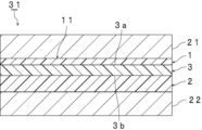
- FIG. 1 is a cross-sectional view schematically showing an interlayer film for laminated glass according to an embodiment of the present invention.
- FIG. 2 is a cross-sectional view schematically showing an example of a laminated glass using the interlayer film for laminated glass shown in FIG. 1.
- interlayer film for laminated glass The interlayer film for laminated glass (herein sometimes abbreviated as “interlayer film”) according to the present invention is used for laminated glass.
- the interlayer film according to the present invention includes a first resin layer containing a thermoplastic resin, a second resin layer containing a thermoplastic resin, and an optical film.
- the first resin layer is disposed on the first surface side of the optical film, and the first resin layer is disposed on the second surface side of the optical film opposite to the first surface.
- the second resin layer is arranged.
- the thickness T1 of the first resin layer is smaller than the thickness T2 of the second resin layer.
- the interlayer film according to the present invention satisfies the following configuration (1) or the following configuration (2).
- the direction in which the resin layer has the maximum thermal contraction rate is the "direction in which the resin layer exhibits the maximum thermal contraction rate.”
- Configuration (1) The direction in which the heat shrinkage rate of the second resin layer is the maximum in the heat shrinkage rate A1 of the first resin layer in the direction in which the heat shrinkage rate of the first resin layer is maximum.
- the ratio (A1/A2) of the second resin layer to the thermal contraction rate A2 is greater than 1 and less than or equal to 5.
- Configuration (2) The direction in which the heat shrinkage rate of the second resin layer is the maximum in the heat shrinkage rate A1 of the first resin layer in the direction in which the heat shrinkage rate of the first resin layer is maximum.
- the ratio (A1/A2) of the second resin layer to the thermal contraction rate A2 exceeds 1.
- the value X obtained from the following formula (X) from the thermal contraction rate A2 of the resin layer, the thickness T1 of the first resin layer, and the thickness T2 of the second resin layer exceeds 0.5. It is 2.5 or less.
- the interlayer film according to the present invention has the above-mentioned configuration, curvature is unlikely to occur.
- the interlayer film according to the present invention in the interlayer film including an optical film, although the thickness T1 of the first resin layer and the thickness T2 of the second resin layer are different, the interlayer film is difficult to curve. can do.
- the intermediate film may satisfy the above configuration (1), the above configuration (2), or the above configuration (1) and the above configuration (2). . From the viewpoint of exhibiting the effects of the present invention even more effectively, it is preferable that the intermediate film satisfies the above configuration (1) and the above configuration (2).
- heat shrinkage rate A1 of the first resin layer in the direction where the heat shrinkage rate of the first resin layer is maximum is abbreviated as "heat shrinkage rate A1 of the first resin layer”.
- heat shrinkage rate A2 of the second resin layer in the direction where the heat shrinkage rate of the second resin layer is maximum is sometimes abbreviated as “heat shrinkage rate A2 of the second resin layer”.
- the thickness T1 of the first resin layer is different from the thickness T2 of the second resin layer.
- the thickness T1 of the first resin layer is smaller than the thickness T2 of the second resin layer. Therefore, in the intermediate film according to the present invention, the ratio (T1/T2) of the thickness T1 of the first resin layer to the thickness T2 of the second resin layer is smaller than 1.
- the ratio (T1/T2) is preferably 0.1 or more, more preferably 0.2 or more, even more preferably 0.3 or more, particularly preferably 0.4 or more, preferably 0.98 or less, and more preferably It is 0.9 or less, more preferably 0.8 or less, particularly preferably 0.7 or less.
- the ratio (T1/T2) is below the above upper limit, curvature is likely to occur, but with the interlayer film according to the present invention, even if the above ratio (T1/T2) is below the above upper limit, the intermediate film The film can be made less likely to curve.
- the thickness of the first resin layer can be reduced, so the cost of the first resin layer can be suppressed and the weight of the interlayer film can be reduced. be able to.
- the ratio (T1/T2) is equal to or higher than the lower limit, it is possible to further prevent the intermediate film from being curved.
- the ratio (T3/T2) of the thickness T3 of the optical film to the thickness T2 of the second resin layer is preferably 0.02 or more, more preferably 0.05 or more, still more preferably 0.10 or more, especially It is preferably 0.13 or more, preferably 0.55 or less, more preferably 0.50 or less, even more preferably 0.30 or less, particularly preferably 0.20 or less.
- the ratio (T3/T2) is equal to or higher than the lower limit, curvature tends to occur, but in the interlayer film according to the present invention, even if the ratio (T3/T2) is equal to or higher than the lower limit, the intermediate film The film can be made less likely to curve. Further, when the ratio (T3/T2) is equal to or less than the upper limit, it is possible to further prevent the intermediate film from being curved.
- the absolute value of the difference between the thickness T1 of the first resin layer and the thickness T2 of the second resin layer is preferably 10 ⁇ m or more, more preferably 100 ⁇ m or more, still more preferably 200 ⁇ m or more, preferably 500 ⁇ m or less, and more.
- the thickness is preferably 400 ⁇ m or less, more preferably 350 ⁇ m or less.
- the thickness T1 of the first resin layer is preferably 100 ⁇ m or more, more preferably 150 ⁇ m or more, still more preferably 200 ⁇ m or more, preferably 800 ⁇ m or less, preferably less than 800 ⁇ m, more preferably 760 ⁇ m or less, more preferably less than 760 ⁇ m, More preferably, it is 720 ⁇ m or less.
- the thickness T1 of the first resin layer is equal to or greater than the lower limit, the handling of the first resin layer when producing an intermediate film can be improved.
- the thickness T1 of the first resin layer is less than or equal to the upper limit (or less than the upper limit) trimming when producing a laminated glass becomes easy.
- the thickness T2 of the second resin layer is preferably more than 100 ⁇ m, more preferably more than 150 ⁇ m, even more preferably more than 200 ⁇ m, particularly preferably 300 ⁇ m or more, most preferably 350 ⁇ m or more, preferably 820 ⁇ m or less, and more preferably is 800 ⁇ m or less, more preferably 780 ⁇ m or less, particularly preferably 760 ⁇ m or less.
- the thickness T2 of the second resin layer is equal to or greater than the lower limit (or exceeds the lower limit)
- the handleability of the second resin layer when producing the intermediate film can be improved.
- trimming when producing a laminated glass becomes easy.
- the thickness T3 of the optical film is preferably 35 ⁇ m or more, more preferably 40 ⁇ m or more, even more preferably 45 ⁇ m or more, preferably 120 ⁇ m or less, more preferably 110 ⁇ m or less, and still more preferably 100 ⁇ m or less.
- the intermediate film according to the present invention even if the thickness T3 is greater than or equal to the lower limit, the intermediate film can be made less likely to curve. Further, when the thickness T3 is equal to or less than the upper limit, it is possible to further prevent the intermediate film from being curved.
- the thickness T1 of the first resin layer, the thickness T2 of the second resin layer, and the thickness T3 of the optical film each mean an average thickness.
- the thickness T1 of the first resin layer means the thickness (same as the average thickness) when the thickness of the first resin layer is uniform; When the thickness is non-uniform, it means the average thickness.
- the thickness T2 of the second resin layer means the thickness (same as the average thickness) when the second resin layer has a uniform thickness, and the thickness T2 when the second resin layer has a non-uniform thickness. In this case, it means the average thickness.
- the thickness T3 of the optical film means the thickness (same as the average thickness) when the thickness of the optical film is uniform, and means the average thickness when the thickness of the optical film is uneven. .
- the ratio (A1/A2) of the thermal contraction rate A1 of the first resin layer to the thermal contraction rate A2 of the second resin layer is greater than 1, preferably 1.25 or more, and more preferably 1.50.
- the number is preferably 5 or less, more preferably 4 or less, and even more preferably 3 or less.
- the value X determined by the above formula (X) preferably exceeds 0.5, more preferably 0.55 or more, even more preferably 0.6 or more, particularly preferably 0.65 or more, and preferably 2.5 or less. , more preferably 2.0 or less, still more preferably 1.5 or less, particularly preferably 1.0 or less.
- curvature can be made even less likely to occur in the interlayer film.
- the heat shrinkage rate A1 of the first resin layer is preferably more than 5%, more preferably more than 7.5%, even more preferably more than 10%, particularly preferably 12.5% or more, and most preferably It is 20% or more, preferably 40% or less, more preferably 35% or less, even more preferably 30% or less.
- the thermal contraction rate A1 of the first resin layer is equal to or higher than the lower limit (or exceeds the lower limit) and equal to or lower than the upper limit, it is possible to further prevent the intermediate film from being curved.
- the heat shrinkage rate A2 of the second resin layer is preferably 5% or more, more preferably 7.5% or more, even more preferably 10% or more, preferably 40% or less, more preferably 35% or less, and even more preferably is less than 30%.
- the thermal contraction rate A2 of the second resin layer is not less than the above lower limit and not more than the above upper limit, it is possible to make it even more difficult for the interlayer film to curve.
- the heat shrinkage rate A3 of the optical film in the direction where the heat shrinkage rate of the optical film is maximum (herein sometimes abbreviated as "heat shrinkage rate A3 of optical film”) is preferably -2 % or more, more preferably -1% or more, still more preferably -0.5% or more, preferably 2% or less, more preferably 1% or less, even more preferably 0.5% or less.
- heat shrinkage rate A3 of optical film is not less than the above lower limit and not more than the above upper limit, it is possible to further prevent the intermediate film from being curved.
- the heat shrinkage rate A1 of the first resin layer may be larger or smaller than the heat shrinkage rate A3 of the optical film.
- the heat shrinkage rate A1 of the first resin layer and the heat shrinkage rate A3 of the optical film may be the same.
- the absolute value of the difference between the heat shrinkage rate A1 of the first resin layer and the heat shrinkage rate A3 of the optical film is preferably 0% or more, preferably 33% or less, more preferably 30% or less, and even more preferably is 25% or less, more preferably 20% or less, even more preferably 15% or less, particularly preferably 8.0% or less.
- the absolute value of the difference between the heat shrinkage rate A1 of the first resin layer and the heat shrinkage rate A3 of the optical film may exceed 0%, may be 0.1% or more, and may be 0.1% or more. It may be 5% or more, or 1.0% or more.
- the heat shrinkage rate A2 of the second resin layer may be larger or smaller than the heat shrinkage rate A3 of the optical film.
- the heat shrinkage rate A2 of the second resin layer and the heat shrinkage rate A3 of the optical film may be the same.
- the absolute value of the difference between the heat shrinkage rate A2 of the second resin layer and the heat shrinkage rate A3 of the optical film is preferably 0% or more, preferably 22% or less, more preferably 20% or less, and even more preferably is 15% or less, more preferably 10% or less, particularly preferably 8.0% or less.
- the absolute value of the difference between the heat shrinkage rate A2 of the second resin layer and the heat shrinkage rate A3 of the optical film may exceed 0%, may be 0.1% or more, and may be 0.1% or more. It may be 5% or more, or 1.0% or more.
- the absolute value of the difference between the heat shrinkage rate A1 of the first resin layer and the heat shrinkage rate A3 of the optical film is 33% or less, or It is preferable that the absolute value of the difference between the heat shrinkage rate A2 of the second resin layer and the heat shrinkage rate A3 of the optical film is 22% or less.
- the absolute value of the difference between the thermal contraction rate A1 of the first resin layer and the thermal contraction rate A3 of the optical film may be 33% or less, and the thermal contraction rate A2 of the second resin layer and the optical
- the absolute value of the difference from the heat shrinkage rate A3 of the film may be 22% or less.
- the absolute value of the difference between the heat shrinkage rate A1 of the first resin layer and the heat shrinkage rate A3 of the optical film is 33% or less, and the difference between the heat shrinkage rate A2 of the second resin layer and the optical film is The absolute value of the difference from the heat shrinkage rate A3 may be 22% or less.
- the larger absolute value of the two absolute values of the difference is preferably 0% or more, preferably 33% or less, more preferably 30% or less, and still more preferably 28% or less.
- the larger absolute value is less than or equal to the upper limit, it is possible to further prevent the interlayer film from being curved.
- the larger absolute value may exceed 0%, may be 0.1% or more, may be 0.5% or more, or may be 1.0% or more.
- Thermal contraction rate B1 of the first resin layer in the direction perpendicular to the direction in which the thermal contraction rate of the first resin layer is maximum (hereinafter referred to as "thermal contraction rate B1 of the first resin layer”) ) is preferably -15% or more, more preferably -10% or more, preferably 0% or less, and more preferably -1% or less.
- thermal contraction rate B1 of the first resin layer is not less than the above lower limit and not more than the above upper limit, it is possible to further prevent the interlayer film from being curved.
- Thermal contraction rate B2 of the second resin layer in the direction perpendicular to the direction in which the thermal contraction rate of the second resin layer is maximum (hereinafter referred to as "thermal contraction rate B2 of the second resin layer”) ) is preferably -10% or more, more preferably -8% or more, preferably 0% or less, and more preferably -1% or less.
- thermal contraction rate B2 of the second resin layer is not less than the above lower limit and not more than the above upper limit, it is possible to make it even more difficult for the interlayer film to curve.
- thermal contraction rate B3 of the optical film in the direction perpendicular to the direction in which the optical film has the maximum thermal contraction rate (herein sometimes abbreviated as "thermal contraction rate B3 of the optical film") is , preferably -1% or more, more preferably -0.5% or more, preferably 1% or less, more preferably 0.5% or less.
- thermal shrinkage rate B3 of the optical film is not less than the above lower limit and not more than the above upper limit, it is possible to make it even more difficult for the intermediate film to be curved.
- the ratio (B1/B2) of the thermal contraction rate B1 of the first resin layer to the thermal contraction rate B2 of the second resin layer is preferably greater than 1.0, more preferably 1.4 or more, and preferably is 5.0 or less, more preferably 4.0 or less, still more preferably 3.0 or less.
- the ratio (B1/B2) is equal to or higher than the lower limit (or exceeds the lower limit) and equal to or lower than the upper limit, it is possible to further prevent the intermediate film from being curved.
- the value Y determined by formula (Y) is preferably 0.45 or more, more preferably 0.65 or more, preferably 2.10 or less, and more preferably 1.60 or less. When the value Y is greater than or equal to the lower limit and less than or equal to the upper limit, it is possible to further prevent the intermediate film from curving.
- the above heat shrinkage rate is measured as follows.
- a first resin layer, a second resin layer, and an optical film constituting the intermediate film are each prepared.
- the first resin layer, the second resin layer, and the optical film may be prepared by peeling off the first resin layer, the second resin layer, and the optical film from the intermediate film.
- the first resin layer, the second resin layer, and the optical film are each heated in water at 60°C for 30 minutes, and then cooled in water at 20°C for 5 minutes. From the dimension L1 of the object to be measured before heating at 60°C for 30 minutes and the dimension L2 of the object to be measured after heating at 60°C for 30 minutes and cooling at 20°C for 5 minutes, calculate the thermal contraction rate using the following formula. calculate.
- Heat shrinkage rate (%) (L1-L2)/L1 ⁇ 100
- L1 Dimensions before heating at 60°C for 30 minutes (mm)
- L2 Dimensions (mm) after heating at 60°C for 30 minutes and cooling at 20°C for 5 minutes
- the intermediate film has an MD direction and a TD direction.
- the interlayer film can be obtained, for example, by extrusion molding.
- the MD direction is the flow direction of the intermediate film during production of the intermediate film.
- the TD direction is a direction perpendicular to the flow direction of the interlayer film during manufacture of the interlayer film, and a direction perpendicular to the thickness direction of the interlayer film.
- the direction in which the thermal shrinkage rate of the first resin layer is maximum is usually the MD direction of the intermediate film.
- the direction in which the second resin layer has a maximum thermal shrinkage rate is usually the MD direction of the intermediate film.
- Methods for reducing the thermal contraction rate A1 of the first resin layer and the thermal contraction rate A2 of the second resin layer include methods of reducing the stress applied to each resin layer, and reducing the stress applied to each resin layer. Examples include methods of alleviating this.
- the intermediate film may have a three-layer structure including the first resin layer, the second resin layer, and the optical film.
- the intermediate film may have a structure of three or more layers.
- FIG. 1 is a cross-sectional view schematically showing an interlayer film for laminated glass according to an embodiment of the present invention.
- FIG. 1 a cross section of the intermediate film 11 in the thickness direction is shown.
- the interlayer film 11 shown in FIG. 1 is used to obtain laminated glass.
- the interlayer film 11 is an interlayer film for laminated glass.
- the intermediate film 11 includes a first resin layer 1 , a second resin layer 2 , and an optical film 3 .
- the first resin layer 1 is arranged on the first surface 3a of the optical film 3 and is laminated.
- a second resin layer 2 is disposed and laminated on a second surface 3b of the optical film 3 opposite to the first surface 3a.
- the first resin layer 1 and the second resin layer 2 are each a protective layer, and in this embodiment, a surface layer.
- the optical film 3 is disposed and sandwiched between the first resin layer 1 and the second resin layer 2.
- the thickness T1 of the first resin layer 1 is smaller than the thickness T2 of the second resin layer 2.
- the interlayer film 11 satisfies the above configuration (1) or the above configuration (2).
- optical film examples include polyethylene terephthalate film (PET film), infrared reflective film, and display film.
- the infrared reflective film examples include a resin film with metal foil, a multilayer laminated film in which a metal layer and a dielectric layer are formed on a resin film, a multilayer resin film, and a liquid crystal film. These films have the ability to reflect infrared radiation.
- the resin film with metal foil includes a resin film and a metal foil laminated on the outer surface of the resin film.
- Materials for the resin film include polyethylene terephthalate resin, polyethylene naphthalate resin, polyvinyl acetal resin, ethylene-vinyl acetate copolymer resin, ethylene-acrylic acid copolymer resin, polyurethane resin, polyvinyl alcohol resin, polyolefin resin, Examples include vinyl chloride resin and polyimide resin.
- Examples of the material for the metal foil include aluminum, copper, silver, gold, palladium, and alloys containing these.
- the multilayer laminate film in which a metal layer and a dielectric layer are formed on a resin film is a multilayer laminate film in which a desired number of metal layers and dielectric layers are alternately laminated on a resin film.
- a metal layer and a dielectric layer are formed on the resin layer, it is preferable that all of the metal layers and dielectric layers are laminated alternately.
- Materials for the resin film in the multilayer laminated film include polyethylene, polypropylene, polylactic acid, poly(4-methylpentene-1), polyvinylidene fluoride, cyclic polyolefin, polymethyl methacrylate, polyvinyl chloride, polyvinyl alcohol, and nylon 6. , 11, 12, 66, polystyrene, polycarbonate, polyethylene terephthalate, polyethylene naphthalate, polyester, polyphenylene sulfide, polyetherimide, and the like.
- Examples of the material for the metal layer in the multilayer laminated film include the same materials as the metal foil in the resin film with metal foil.
- a coating layer of a metal or a mixed oxide of metals can be applied to both or one side of the metal layer.
- Examples of the material for the coat layer include ZnO, Al 2 O 3 , Ga 2 O 3 , InO 3 , MgO, Ti, NiCr, and Cu. Furthermore, examples of the material for the dielectric layer in the multilayer laminated film include indium oxide and the like.
- the multilayer resin film is a laminated film in which a plurality of resin films are laminated.
- Examples of the material for the multilayer resin film include the same materials as the resin film in the multilayer laminate film.
- the number of laminated resin films in the multilayer resin film is 2 or more, may be 3 or more, may be 5 or more, may be 1000 or less, may be 100 or less, and may be 50 or more. It may be the following.
- the multilayer resin film may be a multilayer resin film in which two or more types of thermoplastic resin layers having different optical properties (refractive indexes) are laminated alternately or randomly in an arbitrary number of layers. Such a multilayer resin film is configured to provide desired infrared reflection performance.
- liquid crystal film examples include a film in which cholesteric liquid crystal layers that reflect light of any wavelength are laminated in any number of layers. Such a liquid crystal film is configured to provide desired infrared reflection performance.
- the above-mentioned infrared reflective film may contain infrared reflective particles.
- the above-mentioned infrared reflective particles are particles having infrared reflective performance, and include, for example, tabular grains having a thickness of 1 nm or more and 1000 ⁇ m or less.
- an infrared reflective film having infrared reflective performance can be obtained by adjusting the thickness, surface area, and arrangement of the silver nanotabular particles.
- PET films examples include “Lumirror 100-U34” and “100-U48” manufactured by Toray Industries, Inc., and “Diafoil O-100E” manufactured by Mitsubishi Chemical Corporation.
- examples of commercially available infrared reflective films include “Ultra-multilayer resin film Nano 90S” and “Ultra-multilayer resin film Nano 80S” manufactured by 3M, and "XIR-75” manufactured by Southwall Technologies.
- Examples of the display film include a film containing light-diffusing particles and a thermoplastic resin.
- the display film containing light-diffusing particles and a thermoplastic resin may also contain a plasticizer.
- Examples of the light-diffusing particles include metalloid or metal oxide particles, metal particles, and diamond particles.
- Examples of the semimetal or metal oxide particles include silicon oxide particles (e.g., silica particles), zirconium oxide particles, titanium oxide particles, aluminum oxide particles (e.g., alumina particles), magnesium oxide particles, and cerium oxide particles. It will be done.
- Examples of the metal particles include aluminum particles, silver particles, platinum particles, gold particles, titanium particles, nickel particles, tin particles, indium particles, and tin-cobalt alloy particles.
- the light diffusing particles are preferably metal particles, and preferably silver particles. More preferred.
- the light-diffusing particles may be core-shell particles.
- Core-shell particles are particles that include a core and a shell covering the core. Examples of the core in the core-shell particles include the metalloid or metal oxide particles, metal particles, and diamond particles described above.
- the shell in the core-shell particle is made of a material different from the core, and includes the above-mentioned metalloids or metal oxides, composites of metalloids or metal oxides and polymers, and the like.
- the light-diffusing particles may be core-shell particles having a semimetal or metal oxide as a core and a metal as a shell.
- the core in the core-shell particles, may be a silver particle, and the shell may be a composite of silica, alumina, or a mixture thereof, and a polymer such as polyvinylpyrrolidone.
- the core in the core-shell particles, may be a silica particle and the shell may be silver or other metal.
- the average particle diameter of the light diffusing particles is preferably 1 nm or more, more preferably 3 nm or more, even more preferably 5 nm or more, particularly preferably 10 nm or more, preferably 100 ⁇ m or less, more preferably 50 ⁇ m or less, still more preferably 20 ⁇ m or less, Particularly preferably, the thickness is 5 ⁇ m or less.
- the above-mentioned average particle diameter is at least the above-mentioned lower limit and below the above-mentioned upper limit, visible light is well diffused by the light-diffusing particles, and the contrast of the image when displayed on the laminated glass can be improved.
- the average particle diameter of the light-diffusing particles can be measured by a laser diffraction/scattering method.
- the content of the light diffusing particles in 100% by weight of the display film is preferably 0.00005% by weight or more, more preferably 0.0001% by weight or more, still more preferably 0.0005% by weight or more, and preferably 2% by weight or more.
- the amount is at most 1% by weight, more preferably at most 1% by weight, even more preferably at most 0.5% by weight, particularly preferably at most 0.1% by weight, and most preferably at most 0.03% by weight.
- the content of the light-diffusing particles is equal to or higher than the lower limit, visible light is well diffused by the light-diffusing particles, and images can be displayed appropriately.
- the content of the light-diffusing particles is at most the above-mentioned upper limit, the transparency of the interlayer film can be improved without being excessively blocked by the light-diffusing particles.
- thermoplastic resin in the display film the thermoplastic resins described below in the sections of the first resin layer and second resin layer can be used. Furthermore, as the plasticizer in the display film, the plasticizers described in the section of the first resin layer and second resin layer below can be used.
- the content of the plasticizer in the display film is preferably 20 parts by weight or more, more preferably 30 parts by weight or more, and even more preferably 40 parts by weight.
- the amount is at least 50 parts by weight, particularly preferably at least 50 parts by weight, preferably at most 100 parts by weight, more preferably at most 90 parts by weight, even more preferably at most 85 parts by weight, particularly preferably at most 80 parts by weight.
- the content of the plasticizer is equal to or higher than the lower limit, the flexibility of the interlayer film becomes high, and the interlayer film becomes easy to handle.
- the content of the plasticizer is at most the above upper limit, the penetration resistance of the laminated glass can be improved.
- the optical film is preferably an infrared reflective film, and more preferably a multilayer resin film. From the viewpoint of using the laminated glass as a screen for image display, the optical film is preferably a display film.
- the first resin layer includes a thermoplastic resin (hereinafter sometimes referred to as thermoplastic resin (1)).
- the first resin layer preferably contains polyvinyl acetal resin (hereinafter sometimes referred to as polyvinyl acetal resin (1)) as the thermoplastic resin (1).
- the second resin layer includes a thermoplastic resin (hereinafter sometimes referred to as thermoplastic resin (2)).
- the second resin layer preferably contains polyvinyl acetal resin (hereinafter sometimes referred to as polyvinyl acetal resin (2)) as the thermoplastic resin (2).
- the thermoplastic resin (1) and the thermoplastic resin (2) may be the same or different.
- the polyvinyl acetal resin (1) and the polyvinyl acetal resin (2) may be the same or different. Each of the thermoplastic resin (1) and the thermoplastic resin (2) may be used alone or in combination of two or more. Only one type of the above polyvinyl acetal resin (1) and the above polyvinyl acetal resin (2) may be used, or two or more types thereof may be used in combination.
- thermoplastic resin examples include polyvinyl acetal resin, ethylene-vinyl acetate copolymer resin, ethylene-acrylic acid copolymer resin, polyurethane resin, (meth)acrylic resin, polyolefin resin, ionomer resin, and polyvinyl alcohol resin. It will be done. Thermoplastic resins other than these may also be used.
- the above polyvinyl acetal resin can be produced, for example, by acetalizing polyvinyl alcohol (PVA) with an aldehyde.
- the polyvinyl acetal resin is preferably an acetalized product of polyvinyl alcohol.
- the above polyvinyl alcohol can be obtained, for example, by saponifying polyvinyl acetate.
- the degree of saponification of the polyvinyl alcohol is generally within the range of 70 mol% to 99.9 mol%.
- the average degree of polymerization of the polyvinyl alcohol (PVA) is preferably 200 or more, more preferably 500 or more, even more preferably 1500 or more, even more preferably 1600 or more, particularly preferably 2600 or more, most preferably 2700 or more, Preferably it is 5000 or less, more preferably 4000 or less, still more preferably 3500 or less.
- the average degree of polymerization is equal to or higher than the lower limit, the penetration resistance of the laminated glass becomes even higher.
- the above-mentioned average degree of polymerization is below the above-mentioned upper limit, the interlayer film can be easily formed.
- the average degree of polymerization of the above-mentioned polyvinyl alcohol is determined by a method based on JIS K6726 "Polyvinyl alcohol test method".
- the number of carbon atoms in the acetal group contained in the polyvinyl acetal resin is not particularly limited.
- the aldehyde used in producing the polyvinyl acetal resin is not particularly limited.
- the acetal group in the polyvinyl acetal resin preferably has 3 to 5 carbon atoms, more preferably 3 or 4 carbon atoms. When the number of carbon atoms in the acetal group in the polyvinyl acetal resin is 3 or more, the glass transition temperature of the intermediate film becomes sufficiently low.
- the acetal group in the polyvinyl acetal resin may have 4 or 5 carbon atoms.
- aldehyde is not particularly limited. Generally, aldehydes having 1 to 10 carbon atoms are preferably used. Examples of the aldehyde having 1 to 10 carbon atoms include propionaldehyde, n-butyraldehyde, isobutyraldehyde, n-valeraldehyde, 2-ethylbutyraldehyde, n-hexylaldehyde, n-octylaldehyde, and n-nonylaldehyde. , n-decylaldehyde, formaldehyde, acetaldehyde and benzaldehyde.
- the aldehyde is preferably propionaldehyde, n-butyraldehyde, isobutyraldehyde, n-hexylaldehyde or n-valeraldehyde, more preferably propionaldehyde, n-butyraldehyde or isobutyraldehyde, and n-butyraldehyde. More preferably, it is an aldehyde.
- the above aldehydes may be used alone or in combination of two or more.
- the content of hydroxyl groups in the polyvinyl acetal resin (1) and the polyvinyl acetal resin (2) is preferably 25 mol% or more, more preferably 28 mol% or more, even more preferably 30 mol% or more, and still more preferably More than 31 mol%, even more preferably 31.5 mol% or more, particularly preferably 32 mol% or more, most preferably 33 mol% or more, preferably 38 mol% or less, more preferably 37 mol% or less, even more preferably is 36.5 mol% or less, particularly preferably 36 mol% or less.
- the content of the hydroxyl group is at least the above lower limit or exceeds the above lower limit, the adhesive strength of the interlayer film becomes even higher.
- the flexibility of the interlayer film becomes high, and the interlayer film becomes easy to handle.
- the content of hydroxyl groups in the above-mentioned polyvinyl acetal resin is a value expressed as a percentage of the molar fraction obtained by dividing the amount of ethylene groups to which hydroxyl groups are bonded by the total amount of ethylene groups in the main chain.
- the amount of ethylene groups to which the hydroxyl groups are bonded can be measured, for example, in accordance with JIS K6728 "Test Method for Polyvinyl Butyral.”
- the degree of acetylation of the polyvinyl acetal resin (1) and the polyvinyl acetal resin (2) is preferably 0.01 mol% or more, more preferably 0.5 mol% or more, and preferably 10 mol% or less, More preferably, it is 2 mol% or less.
- the degree of acetylation is equal to or higher than the lower limit, the compatibility between the polyvinyl acetal resin and the plasticizer increases.
- the degree of acetylation is below the upper limit, the interlayer film and the laminated glass will have high moisture resistance.
- the above degree of acetylation is a value expressed as a percentage of the mole fraction obtained by dividing the amount of ethylene groups to which acetyl groups are bonded by the total amount of ethylene groups in the main chain.
- the amount of ethylene groups to which the acetyl groups are bonded can be measured, for example, in accordance with JIS K6728 "Test Method for Polyvinyl Butyral.”
- the degree of acetalization (degree of butyralization in the case of polyvinyl butyral resin) of the polyvinyl acetal resin (1) and the polyvinyl acetal resin (2) is preferably 55 mol% or more, more preferably 60 mol% or more. , preferably 75 mol% or less, more preferably 71 mol% or less.
- degree of acetalization is equal to or higher than the lower limit, the compatibility between the polyvinyl acetal resin and the plasticizer increases.
- the degree of acetalization is below the upper limit, the reaction time required to produce polyvinyl acetal resin becomes short.
- the above degree of acetalization is determined as follows. First, a value is calculated by subtracting the amount of ethylene groups to which hydroxyl groups are bonded and the amount of ethylene groups to which acetyl groups are bonded from the total amount of ethylene groups in the main chain. The obtained value is divided by the total amount of ethylene groups in the main chain to determine the molar fraction. The value expressed as a percentage of this molar fraction is the degree of acetalization.
- the content of hydroxyl groups (amount of hydroxyl groups), the degree of acetalization (degree of butyralization), and the degree of acetylation are preferably calculated from the results measured by a method based on JIS K6728 "Polyvinyl butyral test method". However, measurement according to ASTM D1396-92 may also be used.
- the polyvinyl acetal resin is a polyvinyl butyral resin
- the content of hydroxyl groups (amount of hydroxyl groups), the degree of acetalization (degree of butyralization), and the degree of acetylation are determined according to JIS K6728 "Polyvinyl butyral test method". It can be calculated from the results measured by
- the content of polyvinyl acetal resin in 100% by weight of the thermoplastic resin in the first resin layer is preferably 10% by weight or more, more preferably 30% by weight or more, even more preferably 50% by weight or more, and even more preferably is 70% by weight or more, particularly preferably 80% by weight or more, and most preferably 90% by weight or more.
- the content of polyvinyl acetal resin is preferably 100% by weight or less in 100% by weight of the thermoplastic resin in the first resin layer.
- the main component (50% by weight or more) of the thermoplastic resin in the first resin layer is preferably polyvinyl acetal resin.
- the content of polyvinyl acetal resin in 100% by weight of the thermoplastic resin in the second resin layer is preferably 10% by weight or more, more preferably 30% by weight or more, even more preferably 50% by weight or more, and even more preferably is 70% by weight or more, particularly preferably 80% by weight or more, and most preferably 90% by weight or more.
- the content of polyvinyl acetal resin is preferably 100% by weight or less in 100% by weight of the thermoplastic resin contained in the second resin layer.
- the main component (50% by weight or more) of the thermoplastic resin in the second resin layer is preferably polyvinyl acetal resin.
- the first resin layer preferably contains a plasticizer (hereinafter sometimes referred to as plasticizer (1)).
- the second resin layer preferably contains a plasticizer (hereinafter sometimes referred to as plasticizer (2)).
- the thermoplastic resin contained in the intermediate film is polyvinyl acetal resin, it is particularly preferable that the intermediate film (each layer) contains a plasticizer.
- the layer containing polyvinyl acetal resin preferably contains a plasticizer.
- the above plasticizer is not particularly limited.
- a conventionally known plasticizer can be used.
- the above plasticizers may be used alone or in combination of two or more.
- the plasticizer examples include organic ester plasticizers such as monobasic organic acid esters and polybasic organic acid esters, organic phosphoric acid plasticizers, and organic phosphorous acid plasticizers.
- the plasticizer is an organic ester plasticizer.
- the plasticizer is a liquid plasticizer.
- Examples of the monobasic organic acid ester include glycol esters obtained by reacting glycol with a monobasic organic acid.
- Examples of the glycol include triethylene glycol, tetraethylene glycol, tripropylene glycol, and the like.
- Examples of the monobasic organic acids include butyric acid, isobutyric acid, caproic acid, 2-ethylbutyric acid, heptylic acid, n-octylic acid, 2-ethylhexylic acid, n-nonylic acid, decylic acid, and benzoic acid.
- polybasic organic acid ester examples include ester compounds of a polybasic organic acid and an alcohol having a linear or branched structure having 4 to 8 carbon atoms.
- polybasic organic acids examples include adipic acid, sebacic acid, and azelaic acid.
- organic ester plasticizer examples include triethylene glycol di-2-ethylpropanoate, triethylene glycol di-2-ethyl butyrate, triethylene glycol di-2-ethylhexanoate, triethylene glycol dicaprylate, Triethylene glycol di-n-octanoate, triethylene glycol di-n-heptanoate, tetraethylene glycol di-n-heptanoate, dibutyl sebacate, dioctyl azelate, dibutyl carbitol adipate, ethylene glycol di-2-ethyl butyrate, 1,3-propylene glycol di-2-ethyl butyrate, 1,4-butylene glycol di-2-ethyl butyrate, diethylene glycol di-2-ethyl butyrate, diethylene glycol di-2-ethylhexanoate, dipropylene glycol Di-2-ethyl butyrate, triethylene glycol di-2-eth
- organic phosphoric acid plasticizer examples include tributoxyethyl phosphate, isodecylphenyl phosphate, and triisopropyl phosphate.
- the above plasticizer is preferably a diester plasticizer represented by the following formula (1).
- R1 and R2 each represent an organic group having 2 to 10 carbon atoms
- R3 represents an ethylene group, an isopropylene group, or an n-propylene group
- p represents an integer of 3 to 10.
- R1 and R2 in the above formula (1) are each preferably an organic group having 5 to 10 carbon atoms, more preferably an organic group having 6 to 10 carbon atoms.
- the plasticizer preferably includes triethylene glycol di-2-ethylhexanoate (3GO), triethylene glycol di-2-ethylbutyrate (3GH), or triethylene glycol di-2-ethylpropanoate. .
- the plasticizer more preferably contains triethylene glycol di-2-ethylhexanoate (3GO) or triethylene glycol di-2-ethylbutyrate (3GH), It is more preferable to include ate (3GO).
- the content of the plasticizer (1) based on 100 parts by weight of the thermoplastic resin (1) is defined as content (1).
- the content of the plasticizer (2) relative to 100 parts by weight of the thermoplastic resin (2) is defined as content (2).
- the above content (1) and the above content (2) are each preferably 5 parts by weight or more, more preferably 10 parts by weight or more, even more preferably 15 parts by weight or more, still more preferably 20 parts by weight or more, particularly preferably is 24 parts by weight or more, most preferably 25 parts by weight or more, preferably 45 parts by weight or less, more preferably 40 parts by weight or less, even more preferably 35 parts by weight or less, particularly preferably 32 parts by weight or less, and most preferably 30 parts by weight. below.
- the above content (1) and the above content (2) are at least the above lower limit, the flexibility of the interlayer film becomes high and the interlayer film becomes easy to handle.
- the above content (1) and the above content (2) are below the above upper limits, the penetration resistance of the laminated glass becomes even higher.
- the intermediate film, the first resin layer, and the second resin layer each do not contain or contain a heat-shielding material, and optionally contain a heat-shielding material.
- the intermediate film contains a heat-shielding substance.
- the first resin layer or the second resin layer contains a heat-shielding substance.
- the first resin layer contains a heat-shielding substance.
- the second resin layer contains a heat-shielding substance.
- the first resin layer contains a heat shielding substance, and the second resin layer does not contain a heat shielding substance, or the first resin layer contains no heat shielding substance. It is preferable that the layer contains the heat-shielding substance in an amount smaller than the content of the heat-shielding substance in 100% by weight of the layer. From the viewpoint of further effectively increasing heat shielding properties, it is preferable that the first resin layer contains the heat shielding substance and the second resin layer does not contain the heat shielding substance. As for the above-mentioned heat shielding substance, only one type may be used, or two or more types may be used in combination.
- the heat-shielding substance contains at least one component X of a phthalocyanine compound, a naphthalocyanine compound, and an anthracyanine compound, or contains heat-shielding particles.
- the heat-shielding substance may contain both the component X and the heat-shielding particles.
- the content of the heat-shielding substance (for example, the content of the component The total content with particles) is preferably 0.001% by weight or more, more preferably 0.005% by weight or more, even more preferably 0.01% by weight or more, still more preferably 0.1% by weight or more, Particularly preferably 1% by weight or more, most preferably 1.5% by weight or more, preferably 6% by weight or less, more preferably 5.5% by weight or less, even more preferably 4% by weight or less, particularly preferably 3.5% by weight. % or less, most preferably 3% by weight or less.
- the content of the heat-shielding substance is at least the above-mentioned lower limit and below the above-mentioned upper limit, the heat-shielding property becomes sufficiently high and the visible light transmittance becomes sufficiently high.
- the intermediate film, the first resin layer, and the second resin layer each do not contain or contain at least one component Contains X.
- the intermediate film preferably contains the component X. It is preferable that the first resin layer contains the component X.
- the second resin layer preferably contains the component X.
- the above-mentioned component X is contained in a content smaller than the content of the above-mentioned component X in 100% by weight of the layer. From the viewpoint of further effectively increasing heat shielding properties, it is preferable that the first resin layer contains the component X and the second resin layer does not contain the component X.
- the above component X is a heat shielding substance. The above component X may be used alone or in combination of two or more.
- component X is not particularly limited.
- component X conventionally known phthalocyanine compounds, naphthalocyanine compounds, and anthracyanine compounds can be used.
- the component X examples include phthalocyanine, phthalocyanine derivatives, naphthalocyanine, naphthalocyanine derivatives, anthracyanine, and anthracyanine derivatives. It is preferable that the phthalocyanine compound and the phthalocyanine derivative each have a phthalocyanine skeleton. It is preferable that the naphthalocyanine compound and the naphthalocyanine derivative each have a naphthalocyanine skeleton. It is preferable that the anthracyanine compound and the anthracyanine derivative each have an anthracyanine skeleton.
- the component X is preferably at least one selected from the group consisting of phthalocyanine, phthalocyanine derivatives, naphthalocyanine, and naphthalocyanine derivatives. , phthalocyanine, and phthalocyanine derivatives.
- the component X preferably contains a vanadium atom or a copper atom. It is preferable that the component X contains a vanadium atom, and it is also preferable that the component X contains a copper atom. It is more preferable that the component X is at least one of a phthalocyanine containing a vanadium atom or a copper atom, and a derivative of a phthalocyanine containing a vanadium atom or a copper atom. From the viewpoint of further increasing the heat shielding properties of the interlayer film and the laminated glass, the component X preferably has a structural unit in which an oxygen atom is bonded to a vanadium atom.
- the content of component X in 100% by weight of the intermediate film or in 100% by weight of the layer containing component X (first resin layer or second resin layer) is preferably 0.001% by weight or more, more preferably Preferably 0.005% by weight or more, more preferably 0.01% by weight or more, particularly preferably 0.02% by weight or more, preferably 0.2% by weight or less, more preferably 0.1% by weight or less, even more preferably is 0.05% by weight or less, particularly preferably 0.04% by weight or less.
- the content of the component X is not less than the lower limit and not more than the upper limit, the heat shielding property will be sufficiently high and the visible light transmittance will be sufficiently high. For example, it is possible to increase the visible light transmittance to 70% or more.
- Heat shield particles The intermediate film, the first resin layer, and the second resin layer each do not contain or contain heat-shielding particles, and optionally contain the heat-shielding particles.
- the intermediate film includes heat shielding particles.
- the first resin layer contains the heat shield particles.
- the second resin layer includes the heat shield particles.
- the layer contains heat shielding particles in an amount smaller than the content of heat shielding particles in 100% by weight of the layer.
- the first resin layer contains the heat shield particles and the second resin layer does not contain the heat shield particles.
- the heat-shielding particles are a heat-shielding substance. By using heat shielding particles, infrared rays (heat rays) can be effectively blocked. Only one kind of the above-mentioned heat shielding particles may be used, or two or more kinds may be used in combination.
- the heat shielding particles are more preferably metal oxide particles.
- the heat shielding particles are preferably particles formed of a metal oxide (metal oxide particles).
- infrared rays have a large thermal effect, and when infrared rays are absorbed by substances, they are emitted as heat. For this reason, infrared rays are generally called heat rays.
- heat shielding particles By using the above heat shielding particles, infrared rays (heat rays) can be effectively blocked. Note that the heat shielding particles mean particles that can absorb infrared rays.
- thermal barrier particles include aluminum-doped tin oxide particles, indium-doped tin oxide particles, antimony-doped tin oxide particles (ATO particles), gallium-doped zinc oxide particles (GZO particles), and indium-doped zinc oxide particles (IZO particles).
- tin-doped examples include metal oxide particles such as indium oxide particles (ITO particles), tin-doped zinc oxide particles, and silicon-doped zinc oxide particles, and lanthanum hexaboride (LaB 6 ) particles. Heat shielding particles other than these may also be used.
- Metal oxide particles are preferable because they have a high heat ray shielding function, ATO particles, GZO particles, IZO particles, ITO particles, or tungsten oxide particles are more preferable, and ITO particles or tungsten oxide particles are particularly preferable.
- ITO particles tin-doped indium oxide particles
- tungsten oxide particles are also preferred, since they have a high heat ray shielding function and are easily available.
- the tungsten oxide particles are preferably metal-doped tungsten oxide particles.
- the above-mentioned "tungsten oxide particles” include metal-doped tungsten oxide particles.
- Specific examples of the metal-doped tungsten oxide particles include sodium-doped tungsten oxide particles, cesium-doped tungsten oxide particles, thallium-doped tungsten oxide particles, and rubidium-doped tungsten oxide particles.
- cesium-doped tungsten oxide particles are particularly preferred.
- the cesium-doped tungsten oxide particles are preferably tungsten oxide particles represented by the formula: Cs 0.33 WO 3 .
- the average particle diameter of the heat shielding particles is preferably 0.01 ⁇ m or more, more preferably 0.02 ⁇ m or more, and preferably 0.1 ⁇ m or less, more preferably 0.05 ⁇ m or less.
- the average particle diameter is greater than or equal to the above lower limit, the heat ray shielding properties will be sufficiently high.
- the average particle diameter is below the above upper limit, the dispersibility of the heat shielding particles becomes high.
- the above “average particle diameter” indicates the volume average particle diameter.
- the average particle diameter can be measured using a particle size distribution measuring device ("UPA-EX150” manufactured by Nikkiso Co., Ltd.).
- the content of the heat shielding particles is preferably 0.01% by weight or more in 100% by weight of the intermediate film or 100% by weight of the layer containing the heat shielding particles (first resin layer or second resin layer). , more preferably 0.1% by weight or more, still more preferably 1% by weight or more, particularly preferably 1.5% by weight or more, preferably 6% by weight or less, more preferably 5.5% by weight or less, even more preferably 4 It is not more than 3% by weight, particularly preferably not more than 3.5% by weight, most preferably not more than 3% by weight.
- the content of the heat-shielding particles is at least the above-mentioned lower limit and below the above-mentioned upper limit, the heat-shielding property becomes sufficiently high and the visible light transmittance becomes sufficiently high.
- the intermediate film contains a metal salt.
- the first resin layer contains a metal salt.
- the second resin layer preferably contains a metal salt.
- the metal salt preferably includes an alkali metal salt or an alkaline earth metal salt. In this case, it becomes easy to control the adhesiveness between the interlayer film and the laminated glass member, and the adhesiveness between the first and second resin layers and the optical film.
- alkaline earth metals refer to six types of metals: Be, Mg, Ca, Sr, Ba, and Ra.
- the metal salt preferably contains at least one metal selected from the group consisting of Li, Na, K, Rb, Cs, Mg, Ca, Sr, and Ba.
- the metal salt contained in the interlayer film preferably contains at least one metal selected from K and Mg.
- the metal salt preferably includes a magnesium salt (P) of an organic acid having a branched structure. In this case, it becomes easier to control the adhesiveness between the interlayer film and the laminated glass member, and the adhesiveness between the first and second resin layers and the optical film.
- P magnesium salt
- the magnesium salt (P) of an organic acid having a branched structure is preferably a magnesium salt of a carboxylic acid having a branched structure. In this case, it becomes even easier to control the adhesiveness between the interlayer film and the laminated glass member, and the adhesiveness between the first and second resin layers and the optical film.
- the metal salt is a metal salt other than a magnesium salt of an organic acid having a branched structure, and preferably includes a metal salt (Q) of an organic acid having 2 or more and 8 or less carbon atoms.
- the metal salt (Q) of an organic acid having 2 or more and 8 or less carbon atoms is different from the magnesium salt (P) of an organic acid having a branched structure. Also in this case, it becomes easier to control the adhesiveness between the interlayer film and the laminated glass member, and the adhesiveness between the first and second resin layers and the optical film.
- the metal salt (Q) of an organic acid having 2 or more and 8 or less carbon atoms is preferably a magnesium salt or potassium salt of an organic acid having 2 or more and 8 or less carbon atoms. In this case, it becomes even easier to control the adhesiveness between the interlayer film and the laminated glass member, and the adhesiveness between the first and second resin layers and the optical film.
- the metal salt preferably includes a magnesium salt (P) of the organic acid having the branched structure and a metal salt (Q) of the organic acid having 2 or more and 8 or less carbon atoms.
- an alkali metal salt of an organic acid having 2 to 16 carbon atoms and an alkaline earth metal salt of an organic acid having 2 to 16 carbon atoms can be used.
- the metal salt may include a magnesium salt of a carboxylic acid having 2 to 16 carbon atoms or a potassium salt of a carboxylic acid having 2 to 16 carbon atoms.
- magnesium salt of carboxylic acid having 2 to 16 carbon atoms and the potassium salt of carboxylic acid having 2 to 16 carbon atoms include magnesium acetate, potassium acetate, magnesium propionate, potassium propionate, magnesium 2-ethylbutyrate, and 2-ethylbutanoic acid.
- examples include potassium, magnesium 2-ethylhexanoate, and potassium 2-ethylhexanoate.
- the total content of Mg and K in the intermediate film or the layer containing the metal salt (first resin layer or second resin layer) is preferably 5 ppm or more, more preferably 10 ppm or more, and even more preferably 20 ppm or more. It is preferably 300 ppm or less, more preferably 250 ppm or less, even more preferably 200 ppm or less.
- the total content of Mg and K is more than the above lower limit and less than the above upper limit, the adhesion between the interlayer film and the laminated glass member (glass plate, etc.) and the adhesion between the first and second resin layers and the optical film will be improved. Adhesion can be controlled even better.
- the intermediate film contains an ultraviolet blocking agent.
- the first resin layer contains an ultraviolet shielding agent.
- the second resin layer contains an ultraviolet shielding agent.
- the above-mentioned ultraviolet shielding agent includes an ultraviolet absorber. It is preferable that the ultraviolet screening agent is an ultraviolet absorber.
- ultraviolet screening agents examples include ultraviolet screening agents containing metal atoms, ultraviolet screening agents containing metal oxides, ultraviolet screening agents having a benzotriazole structure (benzotriazole compounds), and ultraviolet screening agents having a benzophenone structure (benzophenone compounds).
- UV screening agents with triazine structure triazine compounds
- UV screening agents with malonic acid ester structure malonic acid ester compounds
- UV screening agents with oxalic acid anilide structure oxalic acid anilide compounds
- benzoate structures examples include ultraviolet shielding agents (benzoate compounds).
- the ultraviolet shielding agent containing metal atoms examples include platinum particles, platinum particles whose surfaces are coated with silica, palladium particles, and palladium particles whose surfaces are coated with silica.
- the ultraviolet screening agent is not a thermal barrier particle.
- the above ultraviolet screening agent is preferably an ultraviolet screening agent having a benzotriazole structure, a benzophenone structure, a triazine structure, or a benzoate structure.
- the ultraviolet screening agent is more preferably an ultraviolet screening agent having a benzotriazole structure or a benzophenone structure, and even more preferably an ultraviolet screening agent having a benzotriazole structure.
- Examples of the ultraviolet shielding agent containing the above-mentioned metal oxide include zinc oxide, titanium oxide, and cerium oxide. Furthermore, the surface may be coated with the ultraviolet shielding agent containing the metal oxide. Examples of the coating material for the surface of the ultraviolet shielding agent containing the metal oxide include insulating metal oxides, hydrolyzable organosilicon compounds, and silicone compounds.
- the insulating metal oxides include silica, alumina, and zirconia.
- the insulating metal oxide has a bandgap energy of, for example, 5.0 eV or more.
- Examples of the ultraviolet screening agent having the benzotriazole structure include 2-(2'-hydroxy-5'-methylphenyl)benzotriazole ("TinuvinP” manufactured by BASF), 2-(2'-hydroxy-3', 5'-di-t-butylphenyl)benzotriazole (BASF "Tinuvin320”), 2-(2'-hydroxy-3'-t-butyl-5-methylphenyl)-5-chlorobenzotriazole (BASF) and 2-(2'-hydroxy-3',5'-di-amylphenyl)benzotriazole ('Tinuvin 328', manufactured by BASF).
- TinuvinP 2-(2'-hydroxy-5'-methylphenyl)benzotriazole
- BASF 2-(2'-hydroxy-3', 5'-di-t-butylphenyl)benzotriazole
- BASF 2-(2'-hydroxy-3', 5'-di-amylphenyl)benzotriazole
- the above-mentioned ultraviolet screening agent is preferably an ultraviolet screening agent having a benzotriazole structure containing a halogen atom, and preferably an ultraviolet screening agent having a benzotriazole structure containing a chlorine atom. More preferred.
- Examples of the ultraviolet shielding agent having the benzophenone structure include octabenzone ("Chimassorb 81" manufactured by BASF) and the like.
- UV shielding agent having the triazine structure examples include "LA-F70” manufactured by ADEKA and 2-(4,6-diphenyl-1,3,5-triazin-2-yl)-5-[(hexyl) Oxy]-phenol ("Tinuvin 1577FF” manufactured by BASF) and the like.
- Examples of the ultraviolet shielding agent having a malonic acid ester structure include 2-(p-methoxybenzylidene) dimethyl malonate, tetraethyl-2,2-(1,4-phenylene dimylidene) bismalonate, and 2-(p-methoxybenzylidene). -bis(1,2,2,6,6-pentamethyl 4-piperidinyl)malonate and the like.
- UV shielding agent having the above-mentioned malonic acid ester structure Commercially available products of the ultraviolet shielding agent having the above-mentioned malonic acid ester structure include Hostavin B-CAP, Hostavin PR-25, and Hostavin PR-31 (all manufactured by Clariant).
- Examples of the ultraviolet screening agent having the oxalic acid anilide structure include N-(2-ethylphenyl)-N'-(2-ethoxy-5-t-butylphenyl)oxalic acid diamide, N-(2-ethylphenyl)- Oxalic acid having an aryl group substituted on the nitrogen atom such as N'-(2-ethoxy-phenyl)oxalic acid diamide, 2-ethyl-2'-ethoxy-oxalanilide ("SanduvorVSU" manufactured by Clariant) Examples include diamides.
- UV screening agent having the benzoate structure examples include 2,4-di-tert-butylphenyl-3,5-di-tert-butyl-4-hydroxybenzoate (“Tinuvin 120” manufactured by BASF). .
- the content of the ultraviolet screening agent is preferably 0.1% by weight or more in 100% by weight of the intermediate film or in 100% by weight of the layer containing the ultraviolet screening agent (first resin layer or second resin layer). , more preferably 0.2% by weight or more, still more preferably 0.3% by weight or more, particularly preferably 0.5% by weight or more, preferably 2.5% by weight or less, more preferably 2% by weight or less, even more preferably is 1% by weight or less, particularly preferably 0.8% by weight or less.
- the content of the ultraviolet screening agent is equal to or higher than the lower limit, the decrease in visible light transmittance after a period of time is further suppressed.
- the content of the ultraviolet shielding agent is below the upper limit, it is possible to significantly suppress a decrease in the visible light transmittance of the interlayer film and the laminated glass after a period of time has elapsed.
- the intermediate film preferably contains an antioxidant.
- the first resin layer preferably contains an antioxidant.
- the second resin layer preferably contains an antioxidant. The above antioxidants may be used alone or in combination of two or more.
- antioxidants examples include phenolic antioxidants, sulfur-based antioxidants, and phosphorus-based antioxidants.
- the above-mentioned phenolic antioxidant is an antioxidant having a phenol skeleton.
- the above-mentioned sulfur-based antioxidant is an antioxidant containing a sulfur atom.
- the above-mentioned phosphorus-based antioxidant is an antioxidant containing a phosphorus atom.
- the above antioxidant is preferably a phenolic antioxidant or a phosphorus antioxidant.
- phenolic antioxidants include 2,6-di-t-butyl-p-cresol (BHT), butylhydroxyanisole (BHA), 2,6-di-t-butyl-4-ethylphenol, and stearyl- ⁇ -(3,5-di-t-butyl-4-hydroxyphenyl)propionate, 2,2'-methylenebis-(4-methyl-6-butylphenol), 2,2'-methylenebis-(4-ethyl-6 -t-butylphenol), 4,4'-butylidene-bis-(3-methyl-6-t-butylphenol), 1,1,3-tris-(2-methyl-hydroxy-5-t-butylphenyl)butane , tetrakis[methylene-3-(3',5'-butyl-4-hydroxyphenyl)propionate]methane, 1,3,3-tris-(2-methyl-4-hydroxy-5-t-butylphenol)butane, 1,3,3-tris-(
- the above phosphorus antioxidants include tridecyl phosphite, tris(tridecyl) phosphite, triphenyl phosphite, trinonylphenyl phosphite, bis(tridecyl)pentaerythritol diphosphite, bis(decyl)pentaerythritol diphosphite, phyto, tris(2,4-di-t-butylphenyl)phosphite, bis(2,4-di-t-butyl-6-methylphenyl)ethyl ester phosphorous acid, and 2,2'-methylenebis(4 , 6-di-t-butyl-1-phenyloxy)(2-ethylhexyloxy)phosphorus, and the like.
- these antioxidants are preferably used.
- antioxidants Commercial products of the above antioxidant include, for example, "IRGANOX 245" manufactured by BASF, "IRGAFOS 168" manufactured by BASF, “IRGAFOS 38" manufactured by BASF, “Sumilyzer BHT” manufactured by Sumitomo Chemical, and “Sumilyzer BHT” manufactured by Sakai Chemical Industries. Examples include “H-BHT” and “IRGANOX 1010" manufactured by BASF.
- the content of the antioxidant is preferably 0.03% by weight or more in 100% by weight of the intermediate film or 100% by weight of the layer containing the antioxidant (first resin layer or second resin layer), More preferably it is 0.1% by weight or more, preferably 2% by weight or less.
- the content of the antioxidant is equal to or higher than the lower limit, the visible light transmittance of the interlayer film and the laminated glass can be maintained high for a long period of time.
- the content of the antioxidant is below the upper limit, the effect of adding the antioxidant is even more effectively exhibited.
- the intermediate film, the first resin layer, and the second resin layer may each contain components other than those described above, if necessary.
- Other ingredients listed above include colorants (pigments, dyes, etc.), coupling agents, dispersants, surfactants, flame retardants, antistatic agents, adhesive force regulators other than metal salts, moisture-resistant agents, and optical brighteners. agents, etc. Each of these other components may be used alone or in combination of two or more.
- the intermediate film has one end and the other end opposite to the one end.
- the one end and the other end are opposite ends of the intermediate film.
- the distance between one end and the other end of the intermediate film is preferably 0.5 m or more, more preferably 0.8 m or more, particularly preferably 1.0 m or more, and preferably 3.0 m or less, more preferably 2.0 m or more. It is 0 m or less, particularly preferably 1.5 m or less.
- the maximum thickness of the intermediate film is preferably 0.1 mm or more, more preferably 0.25 mm or more, even more preferably 0.5 mm or more, particularly preferably 0.8 mm or more, and preferably 3.8 mm or less, more preferably is 2.0 mm or less, more preferably 1.5 mm or less.
- the visible light transmittance of the first resin layer and the visible light transmittance of the second resin layer may be the same or different. From the viewpoint of easily producing intermediate films with different visible light transmittances from various resin layers, the visible light transmittance of the first resin layer and the visible light transmittance of the second resin layer should be different. is preferred. In this case, the visible light transmittance of the first resin layer may be higher or lower than the visible light transmittance of the second resin layer.
- the absolute value of the difference between the visible light transmittance of the first resin layer and the visible light transmittance of the second resin layer may exceed 0%, and may be 0.1% or more, It may be 0.5% or more, 1.0% or more, 50% or less, 30% or less, 20% or less, 10% or more. % or less.
- the visible light transmittance of the first resin layer is preferably 0.5% or more, more preferably 1.0% or more, preferably 90% or less, and more preferably 88% or less.
- the visible light transmittance of the second resin layer is preferably 0.5% or more, more preferably 1.0% or more, preferably 90% or less, and more preferably 88% or less.
- the visible light transmittance of the first resin layer and the second resin layer can be measured as follows.
- a first resin layer and a second resin layer constituting the intermediate film are each prepared.
- the first resin layer and the second resin layer may be prepared by peeling off the first resin layer and the second resin layer from the intermediate film.
- the obtained resin layer (first resin layer or second resin layer) is sandwiched between two pieces of clear glass having a thickness of 2.5 mm in accordance with JIS R3202:1996 to obtain a laminate.
- the obtained laminate was placed in a rubber bag and degassed for 20 minutes at a vacuum level of 2.6 kPa, then transferred to an oven while being degassed, and further held at 90°C for 30 minutes for vacuum pressing, and the laminate was Pre-crimp.
- the pre-pressed laminate is pressed in an autoclave at 135° C. and a pressure of 1.2 MPa for 20 minutes to obtain laminated glass A.
- the visible light transmittance of the laminated glass A is the visible light transmittance of the first resin layer and the second resin layer.
- the visible light transmittance of the laminated glass A can be measured in accordance with JIS R3212:2021 using a spectrophotometer (for example, "U-4150” manufactured by Hitachi High-Tech Corporation). Note that it is preferable to measure the visible light transmittance at a central position in a plan view of the first resin layer and the second resin layer.
- the maximum distance from the surface of the stand to the lower surface of the interlayer film for laminated glass measured by the following measuring method is preferably 15 mm or less, more preferably 9 mm or less, even more preferably 6 mm or less, particularly preferably 4 mm or less, and most preferably is 0 mm.
- the maximum distance is equal to or less than the upper limit, the effects of the present invention are exhibited even more effectively.
- the said maximum distance may be 0 mm or more, may exceed 0 mm, or may be 1 mm or more.
- Method for measuring the maximum distance from the surface of the stand to the bottom surface of the interlayer film for laminated glass After heating the interlayer film for laminated glass with a length of 100 mm and width of 100 mm in water at 60°C for 30 minutes, then in water at 20°C for 5 minutes. Cooling. After cooling, the interlayer film for laminated glass is placed on a horizontal and flat table and left at 20°C for 1 minute, and the maximum distance from the surface of the stand to the bottom surface of the interlayer film for laminated glass is measured. do.
- the intermediate film (measurement sample) with a length of 100 mm and a width of 100 mm for measuring the maximum distance is square in plan view.
- the intersection of the diagonals in the square is at the center of the one end and the other end of the intermediate film.
- the thicker resin layer of the first resin layer and the second resin layer, that is, the second resin layer is used.
- the intermediate film is placed on the stand with the resin layer facing down.
- the intermediate film may be rolled to form a roll of the intermediate film.
- the roll body may include a winding core and an intermediate film wound around the outer periphery of the winding core.
- the method for manufacturing the above intermediate film is not particularly limited.
- the first resin layer and the second resin layer contain the same polyvinyl acetal resin, since the production efficiency of the intermediate film is excellent. Since the production efficiency of the intermediate film is excellent, it is more preferable that the first resin layer and the second resin layer contain the same polyvinyl acetal resin and the same plasticizer. It is further preferable that the first resin layer and the second resin layer are formed of the same resin composition, since the production efficiency of the intermediate film is excellent.
- the first resin layer is preferably a surface layer (first surface layer) of the intermediate film.
- the second resin layer is preferably a surface layer (second surface layer) of the intermediate film.
- the outer surface of the first resin layer (the surface opposite to the optical film) preferably has irregularities.
- the outer surface of the second resin layer (the surface opposite to the optical film) preferably has irregularities.
- the method for forming the above-mentioned irregularities is not particularly limited, and examples thereof include a lip embossing method (melt fracture method), an embossing roll method, a calender roll method, and a profile extrusion method.
- the surface roughness of the outer surface of the first resin layer is defined as surface roughness R1
- the surface roughness of the outer surface of the second resin layer is defined as surface roughness R2.
- the average value of the surface roughness R1 and the surface roughness R2 is defined as the average surface roughness.
- the surface roughness R1 is preferably 15 ⁇ m or more, more preferably 20 ⁇ m or more, preferably 45 ⁇ m or less, and more preferably 40 ⁇ m or less.
- the surface roughness R1 is not less than the lower limit and not more than the upper limit, the degassing performance during pressure bonding between the interlayer film and the laminated glass member can be improved.
- the surface roughness R2 is preferably 15 ⁇ m or more, more preferably 20 ⁇ m or more, preferably 45 ⁇ m or less, and more preferably 40 ⁇ m or less.
- the surface roughness R2 is not less than the lower limit and not more than the upper limit, the degassing performance during pressure bonding between the interlayer film and the laminated glass member can be improved.
- the absolute value of the difference between the surface roughness R1 and the average surface roughness is preferably greater than 1.0 ⁇ m, more preferably 3.0 ⁇ m or more, preferably 20 ⁇ m or less, and more preferably 15 ⁇ m or less.
- the absolute value of the difference between the surface roughness R2 and the average surface roughness is preferably greater than 1.0 ⁇ m, more preferably 3.0 ⁇ m or more, preferably 20 ⁇ m or less, and more preferably 15 ⁇ m or less.
- the above surface roughness R1 and the above surface roughness R2 mean a ten-point average roughness Rz measured in accordance with JIS B0601:1994.
- a measuring instrument for measuring the ten-point average roughness Rz for example, "Surfcorder SE300" manufactured by Kosaka Institute can be used.
- the laminated glass according to the present invention includes a first laminated glass member, a second laminated glass member, and the above-mentioned interlayer film.
- the intermediate film is disposed between the first laminated glass member and the second laminated glass member.
- FIG. 2 is a cross-sectional view schematically showing an example of a laminated glass using the interlayer film for laminated glass shown in FIG. 1.
- the laminated glass 31 shown in FIG. 2 includes a first laminated glass member 21, a second laminated glass member 22, and an interlayer film 11.
- the interlayer film 11 is disposed and sandwiched between the first laminated glass member 21 and the second laminated glass member 22.
- a first laminated glass member 21 is laminated on the first surface of the interlayer film 11.
- a second laminated glass member 22 is laminated on a second surface of the interlayer film 11 opposite to the first surface.
- a first laminated glass member 21 is laminated on the outer surface of the first resin layer 1.
- a second laminated glass member 22 is laminated on the outer surface of the second resin layer 2.
- the above laminated glass may be a head-up display.
- the laminated glass When the laminated glass is a head-up display, the laminated glass has a head-up display display area.
- the display area is an area where information can be displayed well.
- a head-up display system can be obtained using the head-up display described above.
- the head-up display system includes the above laminated glass and a light source device for irradiating the laminated glass with light for image display.
- the light source device can be attached to a dashboard of a vehicle, for example.
- Image display can be performed by irradiating the display area of the laminated glass with light from the light source device.
- the first laminated glass member is a first glass plate.
- the second laminated glass member is preferably a second glass plate.
- first and second laminated glass members include glass plates and PET (polyethylene terephthalate) films.
- the above-mentioned laminated glass includes not only laminated glass in which an interlayer film is sandwiched between two glass plates, but also laminated glass in which an interlayer film is sandwiched between a glass plate and a PET film or the like.
- the laminated glass is a laminate including glass plates, and preferably at least one glass plate is used.
- the first laminated glass member and the second laminated glass member are each a glass plate or a PET film, and the laminated glass is one of the first laminated glass member and the second laminated glass member. It is preferable to provide at least one of the glass plates. It is particularly preferable that both the first and second laminated glass members are glass plates.
- Examples of the glass plate include inorganic glass and organic glass.
- Examples of the inorganic glass include float glass, heat-absorbing glass, heat-reflecting glass, polished glass, patterned glass, wired glass, and green glass.
- the organic glass is a synthetic resin glass that replaces inorganic glass.
- Examples of the organic glass include polycarbonate plates and poly(meth)acrylic resin plates.
- Examples of the poly(meth)acrylic resin board include a polymethyl(meth)acrylate board.
- each of the first laminated glass member and the second laminated glass member is preferably 1 mm or more, preferably 5 mm or less, and more preferably 3 mm or less. Further, when the laminated glass member is a glass plate, the thickness of the glass plate is preferably 0.5 mm or more, more preferably 0.7 mm or more, and preferably 5 mm or less, more preferably 3 mm or less. . When the laminated glass member is a PET film, the thickness of the PET film is preferably 0.03 mm or more, and preferably 0.5 mm or less.
- the method for manufacturing the above laminated glass is not particularly limited. First, an interlayer film is sandwiched between the first laminated glass member and the second laminated glass member to obtain a laminate. Next, for example, the first laminated glass member, the second laminated glass member, and the interlayer film are bonded by passing the obtained laminate through a pressure roll or placing it in a rubber bag and vacuuming it. Evacuate any air remaining in between. Thereafter, the laminate is pre-pressed at about 70° C. to 110° C. to obtain a pre-pressed laminate. Next, the pre-pressed laminate is placed in an autoclave or pressed to be pressed at about 120° C. to 150° C. and a pressure of 1 MPa to 1.5 MPa. In this way, laminated glass can be obtained.
- the interlayer film and the laminated glass can be used in automobiles, railway vehicles, aircraft, ships, buildings, etc.
- the above interlayer film and the above laminated glass can be used for purposes other than these.
- the interlayer film and laminated glass are preferably interlayer films and laminated glass for vehicles or buildings, and more preferably interlayer films and laminated glass for vehicles.
- the above interlayer film and the above laminated glass can be used for automobile windshields, side glasses, rear glasses, roof glasses, backlight glasses, etc.
- the above interlayer film and the above laminated glass are suitably used in automobiles.
- the above interlayer film is suitably used to obtain laminated glass for automobiles.
- the interlayer film and the laminated glass can also be used as an image display screen (hereinafter sometimes abbreviated as "screen”).
- screen For example, light from a light source device that makes up a projector, etc. is irradiated onto one side of laminated glass, and the irradiated light is diffused by an optical film (display film) and displayed as an image on a screen. be done.
- an optical film display film
- the image display screen may be of a rear projection type or a front projection type, but is preferably of a rear projection type. Being a rear projection type makes it easier to display images with high contrast.
- a rear projection type image display screen is a screen that irradiates light from a light source device onto one side of a laminated glass and allows the image to be observed from the other side of the laminated glass.
- a front projection type image display screen irradiates the light from the light source device onto one side of the laminated glass, and from one side of the laminated glass (i.e., the surface irradiated with the light from the light source device). , a screen on which image observation is performed.
- the laminated glass is arranged such that in a vehicle or a building, the first laminated glass member is located at an opening between an external space and an internal space into which heat rays are incident from the external space. and the second laminated glass member can be attached so as to be located on the inner space side.
- the intermediate film may be attached such that the first resin layer is located on the side of the external space and the second resin layer is located on the side of the internal space.
- the first resin layer which is relatively thinner between the first resin layer and the second resin layer, contains the heat-shielding substance, the first resin layer is placed on the outside space side. This position can significantly improve heat shielding properties. Heat rays such as sunlight enter the first resin layer earlier than the second resin layer.
- the heat rays may be reflected by the optical film after passing through the first resin layer and reaching the optical film. Therefore, by increasing the heat shielding properties of the first resin layer among the first resin layer and the second resin layer, the heat shielding properties of the entire intermediate film can be effectively increased. .
- the first laminated glass member in a vehicle or a building, is located at an opening between an external space and an internal space into which heat rays are incident from the external space, and the first laminated glass member is located on the internal space side.
- the second laminated glass member can be attached so as to be located on the outside space side.
- the intermediate film may be attached such that the first resin layer is located on the inner space side and the second resin layer is located on the outer space side.
- n-butyraldehyde having 4 carbon atoms is used for acetalization.
- degree of acetalization degree of butyralization
- degree of acetylation degree of acetylation
- content of hydroxyl groups were measured by a method based on JIS K6728 "Polyvinyl butyral test method”.
- ASTM D1396-92 the same numerical values as in the method based on JIS K6728 "Polyvinyl Butyral Test Method” were shown.
- the following materials for the interlayer film were prepared.
- Optical film (optical film)
- Optical film A infrared reflective film (multilayer resin film), “Multilayer Nano 90S” manufactured by 3M)
- Optical film B infrared reflective film, “XIR-70” manufactured by Southwall
- Optical film C light scattering film, "KALEIDO SCREEN” manufactured by JXTG Energy Corporation
- Polyvinyl acetal resin A polyvinyl butyral resin, average degree of polymerization 1700, hydroxyl group content 30 mol%, degree of acetylation 1 mol%, degree of acetalization (butyralization degree) 69 mol%)
- ITO particles tin-doped indium oxide particles
- Tinuvin326 2-(2'-hydroxy-3'-t-butyl-5-methylphenyl)-5-chlorobenzotriazole ("Tinuvin326" manufactured by BASF)
- Example 1 Preparation of resin composition for forming the first resin layer: The following components were blended and thoroughly kneaded with a mixing roll to obtain a resin composition for forming the first resin layer.
- Polyvinyl acetal resin A 100 parts by weight 3GO: 40 parts by weight ITO particles: 0.3% by weight in the first resin layer obtained Mg mixture: The amount of magnesium in the first resin layer obtained is 70 ppm Tinuvin326: 0.2% by weight in the first resin layer obtained BHT: 0.2% by weight in the first resin layer obtained
- Preparation of resin composition for forming second resin layer The following components were blended and sufficiently kneaded with a mixing roll to obtain a resin composition for forming the second resin layer.
- Polyvinyl acetal resin A 100 parts by weight 3GO: 40 parts by weight
- Mg mixture Amount such that the amount of magnesium in the obtained second resin layer is 70 ppm Tinuvin326: 0.2% by weight in the obtained second resin layer
- Amount BHT 0.2% by weight in the resulting second resin layer
- Preparation of interlayer film A resin composition for forming the first resin layer was extruded using an extruder to obtain a first resin layer. Further, the resin composition for forming the second resin layer was extruded using an extruder to obtain a second resin layer. The heat shrinkage rates of the first resin layer and second resin layer were adjusted by leaving the obtained first resin layer and second resin layer in an oven at 60°C. The first resin layer, optical film A, and second resin layer are laminated in this order to form a three-layer structure (first resin layer (thickness: 370 ⁇ m)/optical film A/second resin layer (thickness: 720 ⁇ m). )) was produced.
- Preparation of laminated glass The obtained interlayer film was sandwiched between two sheets of clear glass (300 mm long x 300 mm wide) having a thickness of 2.5 mm in accordance with JIS R3202:1996 to obtain a laminate.
- the obtained laminate was placed in a rubber bag and degassed for 20 minutes at a vacuum level of 2.6 kPa, then transferred to an oven while being degassed, and further held at 90°C for 30 minutes for vacuum pressing, and the laminate was was pre-crimped.
- the pre-press-bonded laminate was pressure-bonded for 20 minutes in an autoclave at 135° C. and a pressure of 1.2 MPa to obtain a laminated glass.
- Examples 2 to 11 and Comparative Examples 1 to 5 The type of optical film, the composition and thickness of the first and second resin layers were changed as shown in the table below, and the conditions for standing the first and second resin layers in the oven were changed. Except for this, an intermediate film having a three-layer structure (first resin layer/optical film/second resin layer) was produced in the same manner as in Example 1. Note that the metal salt, ultraviolet shielding agent, and antioxidant were used in the same types and amounts as in Example 1. Further, a laminated glass was produced in the same manner as in Example 1 using the obtained interlayer film.
- Heat shrinkage rate (%) (L1-L2)/L1 ⁇ 100
- L1 Dimensions before heating at 60°C for 30 minutes (mm)
- L2 Dimensions (mm) after heating at 60°C for 30 minutes and cooling at 20°C for 5 minutes
- A1 Heat shrinkage rate (%) of the first resin layer in the direction where the heat shrinkage rate of the first resin layer is maximum
- the first resin layer and the second resin layer were peeled off from the obtained intermediate film.
- the obtained resin layer (first resin layer or second resin layer) was sandwiched between two sheets of clear glass having a thickness of 2.5 mm in accordance with JIS R3202:1996 to obtain a laminate.
- the obtained laminate was placed in a rubber bag and degassed for 20 minutes at a vacuum level of 2.6 kPa, then transferred to an oven while being degassed, and further held at 90°C for 30 minutes for vacuum pressing, and the laminate was was pre-crimped.
- the pre-press-bonded laminate was pressure-bonded for 20 minutes in an autoclave at 135° C. and a pressure of 1.2 MPa to obtain laminated glass A.
- the visible light transmittance of the first resin layer and the second resin layer was measured using a spectrophotometer (“U-4150” manufactured by Hitachi High-Tech Corporation) according to the method described above.
- the obtained interlayer film was cut into a size of 100 mm in length and 100 mm in width to obtain a measurement sample.
- the measurement sample was a square in plan view, and the intersection of diagonals in the square was located at the center of the one end and the other end of the interlayer film.
- a measurement sample measuring 100 mm long and 100 mm wide was heated in 60°C water for 30 minutes, and then cooled in 20°C water for 5 minutes.
- the cooled measurement sample was placed on a horizontal and flat table for 1 minute. Note that, between the first resin layer and the second resin layer, the measurement sample is placed on the table with the thicker resin layer, that is, the second resin layer facing down. did.
- the maximum distance from the surface of the stand to the bottom surface of the measurement sample was measured.
- the curvature of the interlayer film was judged based on the following criteria.
- composition and results of the interlayer film are shown in Tables 1 to 12 below.
Abstract
L'invention concerne un film intermédiaire pour un verre feuilleté qui est à peine cintré. Un film intermédiaire pour un verre feuilleté selon la présente invention comprend : une première couche de résine contenant une résine thermoplastique ; une deuxième couche de résine contenant une résine thermoplastique ; et un film optique. La première couche de résine est disposée sur un premier côté de surface du film optique. Le deuxième film de résine est disposé sur un deuxième côté de surface du film optique opposé à la première surface. L'épaisseur T1 de la première couche de résine est inférieure à l'épaisseur T2 de la deuxième couche de résine. Le rapport du taux de retrait thermique A1 de la première couche de résine dans une direction dans laquelle le taux de retrait thermique de la première couche de résine devient maximal au taux de retrait thermique A2 de la deuxième couche de résine dans une direction où le taux de retrait thermique de la deuxième couche de résine devient maximal est supérieur à 1 mais inférieur ou égal à 5.
Applications Claiming Priority (2)
| Application Number | Priority Date | Filing Date | Title |
|---|---|---|---|
| JP2022128242 | 2022-08-10 | ||
| JP2022-128242 | 2022-08-10 |
Publications (1)
| Publication Number | Publication Date |
|---|---|
| WO2024034436A1 true WO2024034436A1 (fr) | 2024-02-15 |
Family
ID=89851630
Family Applications (1)
| Application Number | Title | Priority Date | Filing Date |
|---|---|---|---|
| PCT/JP2023/027809 WO2024034436A1 (fr) | 2022-08-10 | 2023-07-28 | Film intermédiaire pour verre feuilleté et verre feuilleté |
Country Status (1)
| Country | Link |
|---|---|
| WO (1) | WO2024034436A1 (fr) |
Citations (4)
| Publication number | Priority date | Publication date | Assignee | Title |
|---|---|---|---|---|
| JP2018145068A (ja) * | 2017-03-08 | 2018-09-20 | 積水化学工業株式会社 | 合わせガラス用中間膜、合わせガラス、及び、合わせガラスシステム |
| WO2019189741A1 (fr) * | 2018-03-29 | 2019-10-03 | 積水化学工業株式会社 | Film intermédiaire pour verres feuilletés, verre feuilleté et procédé de fabrication de système d'affichage tête haute |
| WO2019203142A1 (fr) * | 2018-04-19 | 2019-10-24 | Agc株式会社 | Verre de portière de véhicules |
| WO2022260084A1 (fr) * | 2021-06-11 | 2022-12-15 | 積水化学工業株式会社 | Film de résine, verre feuilleté et écran |
-
2023
- 2023-07-28 WO PCT/JP2023/027809 patent/WO2024034436A1/fr unknown
Patent Citations (4)
| Publication number | Priority date | Publication date | Assignee | Title |
|---|---|---|---|---|
| JP2018145068A (ja) * | 2017-03-08 | 2018-09-20 | 積水化学工業株式会社 | 合わせガラス用中間膜、合わせガラス、及び、合わせガラスシステム |
| WO2019189741A1 (fr) * | 2018-03-29 | 2019-10-03 | 積水化学工業株式会社 | Film intermédiaire pour verres feuilletés, verre feuilleté et procédé de fabrication de système d'affichage tête haute |
| WO2019203142A1 (fr) * | 2018-04-19 | 2019-10-24 | Agc株式会社 | Verre de portière de véhicules |
| WO2022260084A1 (fr) * | 2021-06-11 | 2022-12-15 | 積水化学工業株式会社 | Film de résine, verre feuilleté et écran |
Similar Documents
| Publication | Publication Date | Title |
|---|---|---|
| WO2017057624A1 (fr) | Couche intermédiaire pour verre feuilleté et verre feuilleté | |
| WO2019189741A1 (fr) | Film intermédiaire pour verres feuilletés, verre feuilleté et procédé de fabrication de système d'affichage tête haute | |
| WO2019189736A1 (fr) | Couche intermédiaire pour verre feuilleté, verre feuilleté et procédé de fixation de système d'affichage tête haute | |
| TWI755512B (zh) | 層合玻璃用中間膜及層合玻璃 | |
| WO2017170727A1 (fr) | Couche intermédiaire pour du verre feuilleté et verre feuilleté | |
| JP7269390B2 (ja) | 合わせガラス用中間膜及び合わせガラス | |
| WO2017170728A1 (fr) | Couche intermédiaire pour verre feuilleté et verre feuilleté | |
| JP5855796B1 (ja) | 合わせガラス用中間膜、合わせガラス用中間膜の製造方法及び合わせガラス | |
| JP2019089703A (ja) | 合わせガラス用中間膜、ロール体及び合わせガラス | |
| EP3357888B1 (fr) | Couche intermédiaire pour verre feuilleté et verre feuilleté | |
| JP7280822B2 (ja) | 合わせガラス | |
| JP7201583B2 (ja) | 合わせガラス | |
| JP7412173B2 (ja) | 合わせガラス | |
| WO2020075747A1 (fr) | Film intermédiaire pour verre feuilleté et verre feuilleté | |
| WO2021200964A1 (fr) | Film de couche intermédiaire pour verre feuilleté, et verre feuilleté | |
| WO2024034436A1 (fr) | Film intermédiaire pour verre feuilleté et verre feuilleté | |
| JP6613094B2 (ja) | 合わせガラス用中間膜及び合わせガラス | |
| WO2018070462A1 (fr) | Film intermédiaire de verre feuilleté, corps laminé, et verre feuilleté | |
| WO2021010402A1 (fr) | Film de couche intermédiaire de verre feuilleté et verre feuilleté | |
| JP7271418B2 (ja) | 合わせガラス用中間膜及び合わせガラス | |
| WO2021010403A1 (fr) | Film intercouche pour verre feuilleté, et verre feuilleté | |
| JP7112386B2 (ja) | 合わせガラス用中間膜及び合わせガラス | |
| JP2019108253A (ja) | 合わせガラス | |
| WO2021117596A1 (fr) | Film de couche intermédiaire de verre feuilleté et verre feuilleté | |
| JP7221690B2 (ja) | 合わせガラス用中間膜 |
Legal Events
| Date | Code | Title | Description |
|---|---|---|---|
| 121 | Ep: the epo has been informed by wipo that ep was designated in this application |
Ref document number: 23852409 Country of ref document: EP Kind code of ref document: A1 |