WO2024033978A1 - 異常検知システム、異常検知装置、異常検知方法、及びコンピュータプログラム - Google Patents
異常検知システム、異常検知装置、異常検知方法、及びコンピュータプログラム Download PDFInfo
- Publication number
- WO2024033978A1 WO2024033978A1 PCT/JP2022/030298 JP2022030298W WO2024033978A1 WO 2024033978 A1 WO2024033978 A1 WO 2024033978A1 JP 2022030298 W JP2022030298 W JP 2022030298W WO 2024033978 A1 WO2024033978 A1 WO 2024033978A1
- Authority
- WO
- WIPO (PCT)
- Prior art keywords
- tool
- abnormality
- abnormality detection
- target data
- unit
- Prior art date
- Legal status (The legal status is an assumption and is not a legal conclusion. Google has not performed a legal analysis and makes no representation as to the accuracy of the status listed.)
- Ceased
Links
Images





Classifications
-
- G—PHYSICS
- G05—CONTROLLING; REGULATING
- G05B—CONTROL OR REGULATING SYSTEMS IN GENERAL; FUNCTIONAL ELEMENTS OF SUCH SYSTEMS; MONITORING OR TESTING ARRANGEMENTS FOR SUCH SYSTEMS OR ELEMENTS
- G05B19/00—Program-control systems
- G05B19/02—Program-control systems electric
- G05B19/18—Numerical control [NC], i.e. automatically operating machines, in particular machine tools, e.g. in a manufacturing environment, so as to execute positioning, movement or co-ordinated operations by means of program data in numerical form
- G05B19/406—Numerical control [NC], i.e. automatically operating machines, in particular machine tools, e.g. in a manufacturing environment, so as to execute positioning, movement or co-ordinated operations by means of program data in numerical form characterised by monitoring or safety
- G05B19/4065—Monitoring tool breakage, life or condition
-
- B—PERFORMING OPERATIONS; TRANSPORTING
- B23—MACHINE TOOLS; METAL-WORKING NOT OTHERWISE PROVIDED FOR
- B23Q—DETAILS, COMPONENTS, OR ACCESSORIES FOR MACHINE TOOLS, e.g. ARRANGEMENTS FOR COPYING OR CONTROLLING; MACHINE TOOLS IN GENERAL CHARACTERISED BY THE CONSTRUCTION OF PARTICULAR DETAILS OR COMPONENTS; COMBINATIONS OR ASSOCIATIONS OF METAL-WORKING MACHINES, NOT DIRECTED TO A PARTICULAR RESULT
- B23Q17/00—Arrangements for observing, indicating or measuring on machine tools
- B23Q17/09—Arrangements for observing, indicating or measuring on machine tools for indicating or measuring cutting pressure or for determining cutting-tool condition, e.g. cutting ability, load on tool
- B23Q17/0952—Arrangements for observing, indicating or measuring on machine tools for indicating or measuring cutting pressure or for determining cutting-tool condition, e.g. cutting ability, load on tool during machining
- B23Q17/0966—Arrangements for observing, indicating or measuring on machine tools for indicating or measuring cutting pressure or for determining cutting-tool condition, e.g. cutting ability, load on tool during machining by measuring a force on parts of the machine other than a motor
-
- G—PHYSICS
- G06—COMPUTING OR CALCULATING; COUNTING
- G06N—COMPUTING ARRANGEMENTS BASED ON SPECIFIC COMPUTATIONAL MODELS
- G06N20/00—Machine learning
-
- G—PHYSICS
- G06—COMPUTING OR CALCULATING; COUNTING
- G06N—COMPUTING ARRANGEMENTS BASED ON SPECIFIC COMPUTATIONAL MODELS
- G06N20/00—Machine learning
- G06N20/10—Machine learning using kernel methods, e.g. support vector machines [SVM]
-
- G—PHYSICS
- G06—COMPUTING OR CALCULATING; COUNTING
- G06N—COMPUTING ARRANGEMENTS BASED ON SPECIFIC COMPUTATIONAL MODELS
- G06N3/00—Computing arrangements based on biological models
- G06N3/02—Neural networks
- G06N3/04—Architecture, e.g. interconnection topology
- G06N3/044—Recurrent networks, e.g. Hopfield networks
-
- G—PHYSICS
- G06—COMPUTING OR CALCULATING; COUNTING
- G06N—COMPUTING ARRANGEMENTS BASED ON SPECIFIC COMPUTATIONAL MODELS
- G06N3/00—Computing arrangements based on biological models
- G06N3/02—Neural networks
- G06N3/04—Architecture, e.g. interconnection topology
- G06N3/045—Combinations of networks
-
- G—PHYSICS
- G06—COMPUTING OR CALCULATING; COUNTING
- G06N—COMPUTING ARRANGEMENTS BASED ON SPECIFIC COMPUTATIONAL MODELS
- G06N3/00—Computing arrangements based on biological models
- G06N3/02—Neural networks
- G06N3/08—Learning methods
-
- G—PHYSICS
- G06—COMPUTING OR CALCULATING; COUNTING
- G06N—COMPUTING ARRANGEMENTS BASED ON SPECIFIC COMPUTATIONAL MODELS
- G06N3/00—Computing arrangements based on biological models
- G06N3/02—Neural networks
- G06N3/08—Learning methods
- G06N3/084—Backpropagation, e.g. using gradient descent
-
- G—PHYSICS
- G05—CONTROLLING; REGULATING
- G05B—CONTROL OR REGULATING SYSTEMS IN GENERAL; FUNCTIONAL ELEMENTS OF SUCH SYSTEMS; MONITORING OR TESTING ARRANGEMENTS FOR SUCH SYSTEMS OR ELEMENTS
- G05B2219/00—Program-control systems
- G05B2219/30—Nc systems
- G05B2219/37—Measurements
- G05B2219/37245—Breakage tool, failure
-
- G—PHYSICS
- G05—CONTROLLING; REGULATING
- G05B—CONTROL OR REGULATING SYSTEMS IN GENERAL; FUNCTIONAL ELEMENTS OF SUCH SYSTEMS; MONITORING OR TESTING ARRANGEMENTS FOR SUCH SYSTEMS OR ELEMENTS
- G05B2219/00—Program-control systems
- G05B2219/30—Nc systems
- G05B2219/37—Measurements
- G05B2219/37274—Strain gauge
Definitions
- the present disclosure relates to an anomaly detection system, an anomaly detection device, an anomaly detection method, and a computer program.
- Patent Document 1 discloses an abnormality detection device that detects an abnormality in a tool attached to a machine tool.
- the abnormality detection device disclosed in Patent Document 1 creates a normal model by learning measurement data of tool vibration information, cutting force information, sound information, spindle load, motor current, and power value using a one-class SVM method. Then, while acquiring measurement data during processing after creating a normal model, it diagnoses whether the measurement data is normal or abnormal based on the normal model.
- the abnormality detection device further re-diagnoses the measurement data diagnosed as abnormal using a method different from the one-class SVM method such as invariant analysis.
- An abnormality detection system is an abnormality detection system that detects an abnormality in a tool attached to a machine tool, and the abnormality detection system detects an abnormality in a tool attached to a machine tool, and the abnormality detection system is such that the tool is a strain sensor that measures strain occurring in the tool; and an abnormality detection device that detects an abnormality in the tool based on measurement data of the strain sensor; a classification unit that is a machine-learned model that receives data as input and outputs classification results of the target data; and an abnormality detection unit that detects abnormalities in the tool based on the classification results of the target data by the classification unit. , and an output section that outputs a detection result by the abnormality detection section.
- the present disclosure can be realized not only as an anomaly detection system having the above-mentioned characteristic configuration, but also as an anomaly detection device included in the anomaly detection system, or as a step-by-step implementation of the characteristic processing in the anomaly detection system. It can be realized as an abnormality detection method.
- the present disclosure can be realized as a computer program that causes a computer to function as an abnormality detection device, or a part or all of the abnormality detection device can be realized as a semiconductor integrated circuit.
- FIG. 1 is a diagram showing an example of the overall configuration of an abnormality detection system according to an embodiment.
- FIG. 2A is a diagram showing an example of the configuration of the cutting tool according to the embodiment.
- FIG. 2B is a diagram showing another example of the configuration of the cutting tool according to the embodiment.
- FIG. 2C is a diagram showing another example of the configuration of the cutting tool according to the embodiment.
- FIG. 2D is a diagram showing another example of the configuration of the cutting tool according to the embodiment.
- FIG. 3 is a diagram showing an example of the configuration of the sensor module according to the embodiment.
- FIG. 4 is a block diagram showing an example of the hardware configuration of the abnormality detection device according to the embodiment.
- FIG. 5 is a functional block diagram showing an example of the functions of the abnormality detection device according to the embodiment.
- FIG. 6 is a graph showing an example of a time-series waveform of distortion of a cutting tool.
- FIG. 7 is a diagram showing an example of a workpiece used in the interrupted machining process.
- FIG. 8A is a graph showing an example of a time-series waveform of distortion of a cutting tool in an interrupted machining process.
- FIG. 8B is a graph showing another example of a time-series waveform of distortion of a cutting tool in an interrupted machining process.
- FIG. 9 is a graph for explaining an example of a learning period of a one-class classifier.
- FIG. 10 is a diagram schematically showing an overview of local outlier factors.
- FIG. 11 is a diagram showing an example of an abnormality notification screen.
- FIG. 12 is a diagram showing an example of an abnormality prediction screen.
- FIG. 13 is a flowchart illustrating an example of abnormality detection processing by the abnormality detection device according to the embodiment.
- FIG. 14 is a flowchart illustrating an example of target data classification processing.
- FIG. 15 is a graph for explaining an example of a learning period of a multi-class classifier.
- the abnormality detection device disclosed in Patent Document 1 uses a vibration sensor that measures the vibration of the tool, but since the vibration sensor measures the vibration of the spindle that is separate from the tool, it is useful for detecting abnormalities in the tool. It is difficult to obtain accurate vibration information.
- the abnormality detection system is an abnormality detection system that detects an abnormality in a tool attached to a machine tool, and the abnormality detection system detects an abnormality in a tool attached to a machine tool.
- a strain sensor that measures strain occurring in a tool; and an abnormality detection device that detects an abnormality in the tool based on measurement data of the strain sensor, the abnormality detection device being based on measurement data of the strain sensor.
- a classification unit that is a machine-learned model that receives target data as input and outputs a classification result of the target data; and an abnormality detection unit that detects an abnormality in the tool based on the classification result of the target data by the classification unit. and an output section that outputs a detection result by the abnormality detection section.
- the strain sensor may be attached to the tool. This allows the distortion sensor to directly measure the distortion of the tool.
- the tool is a cutting tool including a turning tool or a milling tool
- the strain sensor and a wireless communication unit that wirelessly transmits measurement data of the strain sensor are connected to the cutting tool. It may be attached. Accordingly, the strain sensor is attached to a turning tool that does not rotate or a milling tool that rotates, and measurement data can be transmitted wirelessly.
- the classification unit is a one-class classification unit that performs one-class classification
- the anomaly detection unit is configured to detect abnormalities generated in the one-class classification.
- An abnormality in the tool may be detected based on the degree of occurrence.
- tool abnormalities can be detected using a one-class classification section constructed by unsupervised learning.
- the abnormality detection unit performs multi-class classification of the target data by comparing the abnormality degree with a plurality of threshold values, and detects an abnormality of the tool based on the result of the multi-class classification. may be detected. Thereby, tool abnormalities can be accurately detected using the results of multi-class classification of target data.
- the abnormality detection unit classifies the target data into a normal state, a state immediately before an abnormality, and an abnormal state by comparing the degree of abnormality with a first threshold and a second threshold. Good too. This allows the target data to be finely classified using the degree of abnormality.
- the output unit may output information for notifying that the tool is abnormal when the target data is classified as abnormal by the abnormality detection unit. good. Thereby, it is possible to notify the user of the abnormality of the tool.
- the output unit outputs information for notifying that an abnormality is predicted to occur in the tool when the target data is classified as a state immediately before an abnormality by the abnormality detection unit. You can also output it. Thereby, it is possible to notify the user that a tool abnormality is predicted to occur.
- the first threshold value for distinguishing the target data between a normal state and a state immediately before an abnormality is the first threshold value for distinguishing the target data between a normal state and a state immediately before an abnormality. It may be determined based on target data based on measurement data by a strain sensor. Thereby, it is possible to accurately distinguish whether the tool is in a normal state or in a state immediately before an abnormality based on the first threshold value determined based on actually measured data.
- the abnormality detection device is configured to detect, based on measurement data of distortion of the tool in an intermittent machining process that repeats cutting and non-cutting of the workpiece. , an abnormality of the tool may be detected.
- an intermittent machining process the condition of the tool is more likely to be reflected in distortion than in a continuous machining process where cutting of the workpiece is performed continuously. Therefore, tool abnormalities can be accurately detected.
- the abnormality detection device is an abnormality detection device that detects an abnormality in a tool attached to a machine tool, and the abnormality detection device detects an abnormality in a tool attached to a machine tool.
- an acquisition unit that acquires target data based on measurement data output from a strain sensor that measures strain occurring in a tool; and an acquisition unit that receives the target data acquired by the acquisition unit and outputs a classification result of the target data.
- a classification unit that is a machine-learned model that performs the processing, an abnormality detection unit that detects an abnormality in the tool based on the classification result of the target data by the classification unit, and an output unit that outputs the detection result by the abnormality detection unit.
- the abnormality detection method is an abnormality detection method performed by an abnormality detection device that detects an abnormality in a tool attached to a machine tool, in which the machine tool detects a workpiece by the tool. a step of acquiring target data based on measurement data output from a strain sensor that measures distortion occurring in the tool during machining; and using the acquired target data as input and classifying the target data. a step of classifying the target data by a classification unit that is a machine-learned model to be output; a step of detecting an abnormality in the tool based on a classification result of the target data by the classification unit; and a step of detecting an abnormality in the tool. outputting a detection result.
- tool abnormalities can be detected using tool distortion, which is information that accurately reflects the tool condition.
- the computer program according to the present embodiment is a computer program for detecting an abnormality in a tool attached to a machine tool
- the computer program is a computer program for detecting an abnormality in a tool attached to a machine tool.
- tool abnormalities can be detected using tool distortion, which is information that accurately reflects the tool condition.
- FIG. 1 is a diagram showing an example of the overall configuration of an abnormality detection system according to this embodiment.
- the abnormality detection system 10 detects abnormalities in the cutting tool 30 of the machine tool 20.
- Cutting tool 30 is attached to machine tool 20.
- the machine tool 20 uses a cutting tool 30 to cut a workpiece.
- “Cutting” here includes “turning” in which a rotating workpiece is cut by the cutting tool 30, and “turning” in which a fixed workpiece is cut by the rotating cutting tool 30. include.
- the machine tool 20 may be a turning machine such as a lathe, or a turning machine such as a milling machine.
- the abnormality detection system 10 includes a cutting tool 30, a radio 200, and an abnormality detection device 300.
- the radio device 200 is connected to the abnormality detection device 300, for example, by wire.
- Radio device 200 is, for example, an access point.
- the cutting tool 30 includes a sensor module 100. As described later, the sensor module 100 includes a sensor.
- the abnormality detection system 10 is not limited to a configuration including one cutting tool 30 but may include a plurality of cutting tools 30.
- the cutting tool 30 transmits the measurement results of the sensor in the sensor module 100 to the abnormality detection device 300 in time series.
- the cutting tool 30 wirelessly transmits a wireless signal including a packet storing a measured value to the radio device 200.
- the radio device 200 acquires a packet included in the radio signal received from the cutting tool 30 and relays it to the abnormality detection device 300.
- the abnormality detection device 300 When the abnormality detection device 300 receives a sensor packet from the cutting tool 30 via the radio 200, it acquires measurement information from the received sensor packet and processes the acquired measurement information.
- the cutting tool 30 and the radio 200 are, for example, ZigBee (registered trademark) compliant with IEEE 802.15.4, Bluetooth (registered trademark) compliant with IEEE 802.15.1, and UWB compliant with IEEE 802.15.3a.
- Wireless communication is performed using a communication protocol such as (Ultra Wide Band). Note that communication protocols other than those described above may be used between the cutting tool 30 and the radio device 200.
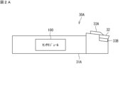
- FIG. 2A is a diagram showing an example of the configuration of the cutting tool according to the present embodiment.
- the turning tool 30A which is an example of the cutting tool 30, is a turning tool used for processing a rotating workpiece, and is attached to a machine tool such as a lathe.
- the turning tool 30A includes a cutting section 31A and a sensor module 100 provided in the cutting section 31A.
- a cutting insert 32 having a cutting edge can be attached to the cutting part 31A.
- the cutting part 31A is a shank that holds the cutting insert 32. That is, the turning tool 30A is a so-called throw-away cutting tool.
- the cutting portion 31A includes fixing members 33A and 33B.
- the fixing members 33A and 33B hold the cutting insert 32.
- the cutting insert 32 has, for example, a polygonal shape such as a triangle, square, rhombus, or pentagon when viewed from above.
- the cutting insert 32 has a through hole formed in the center of its upper surface, and is fixed to the cutting portion 31A by fixing members 33A and 33B.
- FIG. 2B is a diagram showing another example of the configuration of the cutting tool according to the present embodiment.
- the turning tool 30B which is an example of the cutting tool 30, is a turning tool and is attached to a machine tool such as a lathe.
- the turning tool 30B includes a cutting section 31B and a sensor module 100 provided in the cutting section 31B.
- the cutting part 31B has a cutting edge 34. That is, the turning tool 30B is a cutting tool or a brazing tool.
- FIG. 2C is a diagram showing another example of the configuration of the cutting tool according to the present embodiment.
- FIG. 2C shows a cross-sectional view of the cutting tool.
- the milling tool 30C which is an example of the cutting tool 30, is a milling tool used for machining a fixed workpiece, and is attached to a machine tool such as a milling machine.
- the milling tool 30C includes a cutting section 31C and a sensor module 100 provided in the cutting section 31C.
- a cutting insert 32 having a cutting edge can be attached to the cutting part 31C.
- the cutting part 31C is a holder that holds the cutting insert 32. That is, the milling tool 30C is a so-called milling cutter.
- the cutting portion 31C includes a plurality of fixing members 33C.
- the fixing member 33C holds the cutting insert 32.
- the cutting insert 32 is fixed to the cutting part 31C by a fixing member 33C.
- FIG. 2D is a diagram showing another example of the configuration of the cutting tool according to the present embodiment.
- a milling tool 30D which is an example of the cutting tool 30, is a milling tool and is attached to a machine tool such as a milling machine.
- the milling tool 30D includes a cutting section 31D and a sensor module 100 provided in the cutting section 31D.
- the cutting part 31D has a cutting edge 35. That is, the milling tool 30D is an end mill.
- FIG. 3 is a diagram showing an example of the configuration of the sensor module according to the present embodiment.
- the sensor module 100 includes a processor 101, a nonvolatile memory 102, a volatile memory 103, a communication interface (I/F) 104, and strain sensors 110A and 110B.
- the volatile memory 103 is, for example, a volatile memory such as SRAM (Static Random Access Memory) or DRAM (Dynamic Random Access Memory).
- the nonvolatile memory 102 is, for example, a flash memory, a ROM (Read Only Memory), or the like.
- the nonvolatile memory 102 stores, for example, a computer program (not shown) and data used to execute the computer program.
- the computer program is a program for transmitting the measured values of the strain sensors 110A and 110B in time series.
- the processor 101 is, for example, a CPU (Central Processing Unit). However, the processor 101 is not limited to a CPU.
- the processor 101 may be a GPU (Graphics Processing Unit). In a specific example, processor 101 is a multi-core GPU.
- the processor 101 may be, for example, an ASIC (Application Specific Integrated Circuit), or a programmable logic device such as a gate array or an FPGA (Field Programmable Gate Array).
- the communication I/F 104 is, for example, a communication interface for communication protocols such as ZigBee compliant with IEEE 802.15.4, Bluetooth compliant with IEEE 802.15.1, and UWB compliant with IEEE 802.15.3a.
- the communication I/F 104 is realized, for example, by a communication circuit such as a communication IC (Integrated Circuit).
- the sensor module 100 includes a battery 105.
- the battery 105 supplies power to the processor 101, nonvolatile memory 102, volatile memory 103, communication I/F 104, and strain sensors 110A and 110B.
- the strain sensors 110A and 110B are provided near the cutting edge of the cutting tool 30, for example. Strain sensors 110A and 110B are attached to cutting tool 30 so as to measure strain in mutually different directions. For example, the strain sensor 110A measures the strain in the longitudinal direction of the cutting tool 30, and the strain sensor 110B measures the strain in the width direction of the cutting tool 30. Hereinafter, the strain sensors 110A and 110B are also collectively referred to as the strain sensor 110. Strain sensor 110 is an example of a sensor. The sensor is driven by power supplied from the battery 105.
- the sensor module 100 is not limited to a configuration including two strain sensors 110, but may include one or three or more strain sensors 110. Additionally, the sensor module 100 may include other sensors such as an acceleration sensor, a pressure sensor, a sound sensor, and a temperature sensor instead of or in addition to the strain sensor 110.
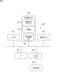
- FIG. 4 is a block diagram showing an example of the hardware configuration of the abnormality detection device according to this embodiment.
- the abnormality detection device 300 includes a processor 301, a nonvolatile memory 302, a volatile memory 303, an input/output interface (I/O) 304, a graphics controller 305, and a display device 306.
- processor 301 a nonvolatile memory 302
- volatile memory 303 a volatile memory 303
- I/O input/output interface
- graphics controller 305 a graphics controller 305
- the volatile memory 303 is, for example, a volatile memory such as SRAM or DRAM.
- the nonvolatile memory 302 is, for example, a flash memory, a hard disk, a ROM, or the like.
- the nonvolatile memory 302 stores an anomaly detection program 307 that is a computer program and data used to execute the anomaly detection program 307. Each function of the abnormality detection device 300 is realized by the abnormality detection program 307 being executed by the processor 301.
- the abnormality detection program 307 can be stored in a recording medium such as a flash memory, ROM, or CD-ROM.
- a measurement result database (DB) 309 is provided in the nonvolatile memory 302.
- the measurement result DB 309 stores measurement results obtained by the strain sensor 110. More specifically, in the measurement result DB 309, measured values of strain output from the strain sensor 110 are accumulated in time series at every fixed sampling period.
- a classifier 310 is stored in the nonvolatile memory 302.
- the classifier 310 is a machine learned model and is an example of a classification unit.
- the classifier 310 will be described later.
- the processor 301 is, for example, a CPU.
- Processor 301 may be one or more CPUs. However, the processor 301 is not limited to a CPU.
- Processor 301 may be a GPU. In one specific example, processor 301 is a multi-core GPU.
- the processor 301 may be, for example, an ASIC, or a programmable logic device such as a gate array or FPGA. In this case, the ASIC or programmable logic device is configured to be able to execute the same process as the abnormality detection program 307.
- the I/O 304 is connected to the radio 200.
- the I/O 304 is, for example, a communication I/F, and can perform communication using a specific communication protocol.
- I/O 304 includes, for example, an Ethernet interface (“Ethernet” is a registered trademark).
- the I/O 304 can receive the measurement results of the strain sensor 110 from the cutting tool 30 via the radio 200.
- the graphic controller 305 is connected to the display device 306 and controls the display on the display device 306.
- the graphic controller 305 includes, for example, a GPU and a VRAM (Video RAM), holds data to be displayed on the display device 306 in the VRAM, periodically reads one frame worth of video data from the VRAM, and generates a video signal. The generated video signal is output to the display device 306, and the video is displayed on the display device 306.
- the functionality of graphics controller 305 may be included in processor 301. A part of the volatile memory 303 may be used as a VRAM.
- the display device 306 includes, for example, a liquid crystal panel or an OEL (organic electroluminescence) panel.
- the display device 306 can display text or graphic information.
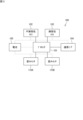
- FIG. 5 is a functional block diagram showing an example of the functions of the abnormality detection device according to the embodiment.
- the anomaly detection device 300 has the following functions: a classifier 310 , an input section 311 , an anomaly detection section 313 , and an output section 314 .
- the input unit 311 acquires measurement data of distortion generated in the cutting tool 30 while the machine tool 20 processes the workpiece with the cutting tool 30.
- the input unit 311 receives distortion measurement data from the measurement result DB 309.
- the measurement data is data of measured values of the strain sensor 110, and is, for example, time series data of measured values of strain.
- the classifier 310 is a machine learned model.
- the classifier 310 inputs target data based on measurement data of distortion of the cutting tool 30 while the machine tool 20 is machining a workpiece with the cutting tool 30, and outputs a classification result of the target data.
- FIG. 6 is a graph showing an example of a time-series waveform of distortion of a cutting tool.
- the vertical axis shows distortion
- the horizontal axis shows time.
- Cutting a workpiece includes a plurality of steps with different processing conditions. For example, turning a single workpiece using a lathe includes a plurality of outer diameter machining steps and a plurality of inner diameter machining steps.
- the waveform pattern of the measured value of distortion of the cutting tool 30 changes for each process.
- a process A, a process B, a process C, a process D, a process E, and a process F are included in the cutting process of one workpiece.
- Process A is executed in period P1
- process B is executed in period P2
- process C is executed in period P3
- process D is executed in period P4
- process E is executed in period P5
- process F is executed in period P6. is executed. Processing conditions for each of process A, process B, process C, process D, process E, and process F are different from each other. Therefore, the distortion waveform patterns in each of Step A, Step B, Step C, Step D, Step E, and Step F are different from each other.
- the abnormality detection device 300 analyzes measurement data of one process (hereinafter also referred to as "target process") selected from the plurality of processes as described above, and detects an abnormality in the cutting tool 30.
- target process is an intermittent machining process that repeats cutting and non-cutting of the workpiece.
- FIG. 7 is a diagram showing an example of a workpiece used in the interrupted machining process.
- the workpiece 400 has a plurality of grooves 401 extending in the axial direction on the outer periphery of the cylinder. That is, in the workpiece 400, the arcuate surfaces 402 and the grooves 401 are arranged alternately in the circumferential direction. In such an outer diameter machining step of the workpiece 400, the workpiece 400 rotates in the circumferential direction (arrow direction), and the cutting tool 30 processes the outer peripheral surface of the workpiece 400. The cutting edge of the cutting tool 30 repeatedly contacts the arcuate surface 402 (cutting) and passes through the groove 401 (non-cutting).
- FIG. 8A is a graph showing an example of a time-series waveform of cutting tool distortion in an interrupted machining process
- FIG. 8B is a graph showing another example of a time-series waveform of cutting tool distortion in an interrupted machining process.
- FIG. 8A is a graph when the measurement time is 14 seconds
- FIG. 8B is a graph when the measurement time is 1.5 seconds.
- the vertical axis represents strain
- the horizontal axis represents time.
- the scale of the time axis (length corresponding to unit time) in FIG. 8B is larger than the scale of the time axis in FIG. 8A.
- the target data is, for example, feature data that includes feature amounts of measured values of distortion of the cutting tool 30.
- the abnormality detection device 300 further has the function of a converter 312.
- the conversion unit 312 converts the measured value of distortion into a feature amount and generates target data.
- the distortion feature amount is, for example, a moving average value of measured distortion values.
- Another example of a distortion feature is a moving standard deviation of distortion measurements.
- Yet another example of the distortion feature is the difference between the percentiles of the measured distortion values, and one specific example is the difference between the 95th percentile and the 5th percentile.
- Yet another example of the distortion feature is the RMS (root mean square) of the value obtained after filtering the distortion measurement value with a bandpass filter.
- the target data may be measurement data of distortion of the cutting tool 30 (so-called raw data).
- the converter 312 may be omitted.
- the classifier 310 is a one-class classifier (one-class classification unit).
- Classifier 310 which is a one-class classifier, is constructed by unsupervised learning.
- FIG. 9 is a graph for explaining an example of the learning period of a one-class classifier.
- the vertical axis shows distortion, and the horizontal axis shows time.
- an abnormality has occurred in the cutting tool 30 at a point indicated as "abnormality" (hereinafter referred to as "abnormality occurrence point").
- the cutting tool 30 is normal from the beginning of machining to before the abnormality occurrence point.
- the learning period is set to a period during which the cutting tool 30 is normal. That is, in the learning of the classifier 310, among the measurement data stored in the measurement result DB 309, measurement data during the learning period is used as learning data.
- the classifier 310 captures the characteristics of the measurement data when the cutting tool 30 is normal (hereinafter also referred to as “normal data”), and determines whether the cutting tool 30 has characteristics different from the characteristics of the normal data.
- Measurement data in abnormal cases (hereinafter also referred to as “abnormal data”) can be distinguished from normal data.
- classifier 310 is a local outlier factor (LOF).
- LEF local outlier factor
- FIG. 10 is a diagram schematically showing an overview of local outlier factors.
- LOF is one of the outlier detection algorithms that detect outliers from a set of data.
- the local density (indicated by the dashed circle in the figure) is calculated for each point from the distance to k neighboring points, and the local density of the point of interest A is compared with the neighboring group to determine the local density of the point of interest. If the value is low, the point of interest is determined to be an abnormal value (outlier).
- Equation (1) Let k-distance (A) be the distance from point A to the k-th neighbor, and let N k (A) be the set of k-nearest neighbors.
- the reachability distance k (A,B) of point A from point B is defined by equation (1).
- the local reachability density lrd k (A) of point A is defined by equation (2).
- the calculated LOF indicates the degree of equality between the local density of the point of interest A and the local density of neighboring points.
- the lower the LOF the higher the local density of the point of interest A, and the higher the possibility that the point of interest A is normal data.
- the higher the LOF the lower the local density of the attention level A, and the higher the possibility that the attention point A is abnormal data.
- the LOF is an outlier score and is an example of the degree of abnormality.
- the classifier 310 is not limited to LOF.
- the classifier 310 may be a one-class classifier other than LOF.
- the classifier 310 may be an Isolation Forest.
- Yet another example of classifier 310 is a one-class SVM.
- the abnormality detection unit 313 detects an abnormality in the cutting tool 30 based on the classification results of the target data by the classifier 310. Specifically, the abnormality detection unit 313 detects an abnormality in the cutting tool 30 based on the degree of abnormality generated in one class classification by the classifier 310.
- the abnormality detection unit 313 performs multi-class classification of the target data by comparing the degree of abnormality with a plurality of threshold values, and detects an abnormality in the cutting tool 30 based on the result of the multi-class classification.
- the abnormality detection unit 313 classifies the target data into a normal state, a state immediately before an abnormality, and an abnormal state by comparing the degree of abnormality with a first threshold value and a second threshold value.
- the first threshold is used to distinguish target data into a normal class, a class immediately before an abnormality, and a set of abnormal classes.
- the normal class is a class of target data in which the cutting tool 30 is normal
- the abnormal class is a class of target data in which the cutting tool 30 is abnormal
- the immediately before abnormality class is a class of target data in which the cutting tool 30 is immediately before abnormality. It is a class of data.
- the normal state here is a state in which the cutting tool 30 can normally process the workpiece, and even if the cutting tool 30 continues to be used as it is, it will not become abnormal for a while.
- the abnormal state is a state in which the cutting tool 30 cannot normally process the workpiece.
- the immediately abnormal state is an intermediate state between the normal state and the abnormal state of the cutting tool 30, in which the cutting tool 30 can normally machine the workpiece, but if the cutting tool 30 continues to be used The situation is about to become abnormal soon.
- the first threshold is a smaller value than the second threshold. If the degree of abnormality (LOF) is less than or equal to the first threshold, the target data belongs to the normal class. When the degree of abnormality is greater than the first threshold, the target data belongs to the class immediately before abnormality or the abnormal class. When the degree of abnormality is less than or equal to the second threshold, the target data belongs to the normal class or the class immediately before abnormality. If the degree of abnormality is greater than the second threshold, the target data belongs to the abnormal class. That is, when the degree of abnormality is greater than the first threshold and less than or equal to the second threshold, the target data belongs to the immediately before abnormality class.
- LEF degree of abnormality
- the first threshold is, for example, 1, and the second threshold is a value greater than 1, for example, 1.25.
- the abnormality detection unit 313 detects an abnormality in the cutting tool 30 when the degree of abnormality is greater than the second threshold. If the degree of abnormality is greater than the first threshold and less than or equal to the second threshold, the abnormality detection unit 313 can determine that the cutting tool 30 is in a state immediately before abnormality. That is, the abnormality detection unit 313 can predict the occurrence of an abnormality in the cutting tool 30.
- the output unit 314 outputs the detection result of the abnormality of the cutting tool 30 by the abnormality detection unit 313.
- the output unit 314 when the abnormality detection unit 313 detects an abnormality in the cutting tool 30, the output unit 314 outputs information for notifying the user of the occurrence of the abnormality.
- the output unit 314 causes the display device 306 to display a screen for notifying the occurrence of an abnormality in the cutting tool 30 (hereinafter also referred to as an “abnormality notification screen”).
- FIG. 11 is a diagram showing an example of an abnormality notification screen.
- the abnormality notification screen 500 includes characters, figures, colors, or a combination thereof for notifying the occurrence of an abnormality in the cutting tool 30.
- the abnormality notification screen 500 includes the words "An abnormality has occurred in the tool.” Thereby, it is possible to notify the user of an abnormality in the cutting tool 30.
- the output unit 314 when the abnormality detection unit 313 predicts the occurrence of an abnormality in the cutting tool 30, the output unit 314 outputs information for notifying the user that the abnormality is predicted to occur.
- the output unit 314 causes the display device 306 to display a screen for notifying that an abnormality in the cutting tool 30 is predicted to occur.
- FIG. 12 is a diagram showing an example of an abnormality prediction screen.
- the abnormality prediction screen 510 includes characters, figures, colors, or a combination thereof for notifying that an abnormality of the cutting tool 30 is predicted to occur.
- the abnormality prediction screen 510 includes the text "An abnormality will occur in the tool soon." Thereby, it is possible to notify the user that an abnormality in the cutting tool 30 is predicted to occur.
- FIG. 13 is a flowchart illustrating an example of abnormality detection processing by the abnormality detection device according to the embodiment.
- the strain sensor 110 measures the strain of the cutting tool 30.
- the sensor module 100 wirelessly transmits the measurement results by the strain sensor 110 to the abnormality detection device 300.
- the abnormality detection device 300 receives the measurement results of distortion, and stores the measurement results in the measurement result DB 309. In this way, measurement data is accumulated in the measurement result DB 309.
- the processor 301 acquires measurement data of the distortion of the cutting tool 30 from the measurement result DB (step S101).
- the processor 301 calculates a feature amount from the measured value of the acquired measurement data and generates feature data (step S102). However, if the target data is measurement data, step S102 can be omitted.
- the processor 301 executes the classification process (1 class classification) of the target data by the classifier 310 (step S103).
- FIG. 14 is a flowchart illustrating an example of target data classification processing. In FIG. 14, classification processing using LOF is shown.
- the processor 301 calculates the reachability distance using equation (1) described above (step S201).
- the processor 301 calculates the local reachability density using equation (2) described above (step S202).
- the processor 301 calculates the LOF (degree of abnormality) using equation (3) described above (step S203).
- the processor 301 classifies the target data by LOF (step S203). That is, it is determined whether the target data is an outlier (abnormal value). However, when performing multi-class classification based on the degree of abnormality, the result of step S204 is not used. In this case, step S204 may be omitted. This completes the classification process.
- the processor 301 classifies the target data into multiple classes using the degree of abnormality calculated by the classifier 310 (step S104). That is, the processor 301 compares the degree of abnormality with the first threshold value and the second period visual position, and classifies the target data into a normal class, a class immediately before an abnormality, and an abnormal class.
- the processor 301 determines whether the classification result is an abnormal class (step S105). If the classification result is an abnormal class (YES in step S105), that is, if an abnormality in the cutting tool 30 is detected, the processor 301 displays the abnormality notification screen 500 on the display device 306 (step S107).
- the processor 301 determines whether the classification result is a class immediately before abnormality (step S106). If the classification result is the immediately before abnormality class (YES in step S106), that is, if the occurrence of an abnormality in the cutting tool 30 is predicted, the processor 301 displays the abnormality prediction screen 510 on the display device 306 (step S107).
- the abnormality detection process ends. If the classification result is a normal class (NO in step S106), the processor 301 ends the abnormality detection process.
- the target data includes not only data based on measurement data of distortion of the cutting tool 30 (characteristic data or measurement data; hereinafter also referred to as “distortion data”), but also data based on measurement data of acceleration of the cutting tool 30 (characteristic data or measurement data. measurement data (hereinafter also referred to as “acceleration data”). That is, the target data may be a combination of strain data and acceleration data at the same time.
- the acceleration of the cutting tool 30 is measured, for example, by an acceleration sensor (not shown) attached to the main shaft of the machine tool 20.
- the conversion unit 312 may generate not only distortion feature data but also acceleration feature data.
- the feature quantity of acceleration is, for example, the RMS of the measured value of acceleration.
- Another example of the feature amount of acceleration is the moving standard deviation of the measured value of acceleration.
- Yet another example of the feature quantity of acceleration is a percentile of a measured value of acceleration, and a specific example is the 95th percentile or the 5th percentile.
- Yet another example of the feature amount of acceleration is the difference between percentiles of measured values of acceleration, and a specific example is the difference between the 95th percentile and the 5th percentile.
- Yet another example of the feature quantity of acceleration is the RMS of the value obtained after filtering the measured value of acceleration with a band-pass filter.
- Yet another example of the feature quantity of acceleration is the kurtosis of time-series measured values of acceleration.
- Yet another example of the feature amount of acceleration is the degree of skewness of time-series measured values of acceleration.
- the classifier 310 is a one-class classifier, but the present invention is not limited to this. Classifier 310 may be a multi-class classifier.
- the classifier 310 which is a multi-class classifier, performs multi-class classification of target data.
- the classifier 310 classifies the target data into a normal class, a class immediately before an abnormality, and an abnormal class.
- Classifier 310 which is a multi-class classifier, is constructed by supervised learning.
- FIG. 15 is a graph for explaining an example of the learning period of a multi-class classifier.
- the vertical axis shows distortion
- the horizontal axis shows time.
- measurement data when the cutting tool 30 is in a normal state measurement data when the cutting tool 30 is in a state immediately before an abnormality
- measurement data when the cutting tool 30 is in an abnormal state are used.
- the learning period includes a period in which the cutting tool 30 is in a normal state (normal period), a period in which the cutting tool 30 is in a state immediately before abnormality (period immediately before abnormality), and a period in which the cutting tool 30 is in an abnormal state (abnormal period).
- the classifier 310 distinguishes between the characteristics of measurement data when the cutting tool 30 is in a normal state (normal data) and the measurement data when the cutting tool 30 is in a state immediately before an abnormality (hereinafter referred to as "immediately before abnormality data"). It is possible to distinguish between normal data, data immediately before an abnormality, and abnormal data by capturing the characteristics of the measured data (also referred to as abnormal data) and the characteristics of the measurement data (abnormal data) when the cutting tool 30 is in an abnormal state.
- multi-class classification of target data is performed using the degree of abnormality calculated by a one-class classifier, but the present invention is not limited to this.
- An abnormality in the cutting tool 30 may be detected by the classifier 310, which is a one-class classifier, detecting an outlier (abnormal data).
- a cutting period is set in the intermittent machining process, and an abnormality of the cutting tool in the intermittent machining process is detected, but the present invention is not limited to this.
- a cutting period may be set in the continuous machining process, and an abnormality of the cutting tool in the continuous machining process may be detected.
- a period including one or more interrupted machining steps and one or more continuous machining steps may be set as the cutting period, and an abnormality of the cutting tool during the cutting period may be detected.
- Abnormality detection system 20 Machine tool 30 Cutting tool 30A, 30B Turning tool 30C, 30D Milling tool 31A, 31B, 31C, 31D Cutting part 32 Cutting insert 33A, 33B, 33C Fixing member 34, 35 Cutting blade 100 Sensor module 101 Processor 102 Non-volatile memory 103 Volatile memory 104 Communication interface (communication I/F) 105 Battery 110, 110A, 110B Strain sensor 200 Wireless device 300 Abnormality detection device 301 Processor 302 Nonvolatile memory 303 Volatile memory 304 Input/output interface (I/O) 305 Graphic controller 306 Display device 307 Abnormality detection program 308 Standard data 309 Measurement result DB 310 Classifier (classification section) 311 Input section 312 Conversion section 313 Abnormality detection section 314 Output section 400 Workpiece 401 Groove 402 Arc surface 500 Abnormality notification screen 510 Abnormality prediction screen A, B, C, D, E, F Process P1, P2, P3, P4, P5, P6 period
Landscapes
- Engineering & Computer Science (AREA)
- Theoretical Computer Science (AREA)
- Physics & Mathematics (AREA)
- Software Systems (AREA)
- General Physics & Mathematics (AREA)
- Computing Systems (AREA)
- Artificial Intelligence (AREA)
- Mathematical Physics (AREA)
- Data Mining & Analysis (AREA)
- Evolutionary Computation (AREA)
- General Engineering & Computer Science (AREA)
- Biophysics (AREA)
- Molecular Biology (AREA)
- General Health & Medical Sciences (AREA)
- Computational Linguistics (AREA)
- Biomedical Technology (AREA)
- Life Sciences & Earth Sciences (AREA)
- Health & Medical Sciences (AREA)
- Computer Vision & Pattern Recognition (AREA)
- Medical Informatics (AREA)
- Mechanical Engineering (AREA)
- Human Computer Interaction (AREA)
- Manufacturing & Machinery (AREA)
- Automation & Control Theory (AREA)
- Machine Tool Sensing Apparatuses (AREA)
- Numerical Control (AREA)
- Testing Of Devices, Machine Parts, Or Other Structures Thereof (AREA)
Priority Applications (4)
| Application Number | Priority Date | Filing Date | Title |
|---|---|---|---|
| CN202280098413.0A CN119585077A (zh) | 2022-08-08 | 2022-08-08 | 异常检测系统、异常检测装置、异常检测方法以及计算机程序 |
| PCT/JP2022/030298 WO2024033978A1 (ja) | 2022-08-08 | 2022-08-08 | 異常検知システム、異常検知装置、異常検知方法、及びコンピュータプログラム |
| JP2022576538A JP7276631B1 (ja) | 2022-08-08 | 2022-08-08 | 異常検知システム、異常検知装置、異常検知方法、及びコンピュータプログラム |
| EP22954900.1A EP4570429A4 (en) | 2022-08-08 | 2022-08-08 | ANOMALY DETECTION SYSTEM, ANOMALY DETECTION DEVICE, ANOMALY DETECTION METHOD AND COMPUTER PROGRAM |
Applications Claiming Priority (1)
| Application Number | Priority Date | Filing Date | Title |
|---|---|---|---|
| PCT/JP2022/030298 WO2024033978A1 (ja) | 2022-08-08 | 2022-08-08 | 異常検知システム、異常検知装置、異常検知方法、及びコンピュータプログラム |
Publications (1)
| Publication Number | Publication Date |
|---|---|
| WO2024033978A1 true WO2024033978A1 (ja) | 2024-02-15 |
Family
ID=86378088
Family Applications (1)
| Application Number | Title | Priority Date | Filing Date |
|---|---|---|---|
| PCT/JP2022/030298 Ceased WO2024033978A1 (ja) | 2022-08-08 | 2022-08-08 | 異常検知システム、異常検知装置、異常検知方法、及びコンピュータプログラム |
Country Status (4)
| Country | Link |
|---|---|
| EP (1) | EP4570429A4 (https=) |
| JP (1) | JP7276631B1 (https=) |
| CN (1) | CN119585077A (https=) |
| WO (1) | WO2024033978A1 (https=) |
Families Citing this family (4)
| Publication number | Priority date | Publication date | Assignee | Title |
|---|---|---|---|---|
| CN116922159B (zh) * | 2023-09-19 | 2023-12-01 | 上海航天壹亘智能科技有限公司 | 智能刀柄的加工方法及系统 |
| CN117047574B (zh) * | 2023-10-13 | 2023-12-26 | 歌玛磨具南通有限公司 | 一种磨料砂轮外圆加工装置 |
| CN117313957B (zh) * | 2023-11-28 | 2024-02-27 | 威海华创软件有限公司 | 基于大数据分析的生产流水任务量智能预测方法 |
| JP7768448B1 (ja) * | 2024-08-05 | 2025-11-12 | 住友電気工業株式会社 | 表示装置、集約装置、表示方法、システムおよびコンピュータプログラム |
Citations (5)
| Publication number | Priority date | Publication date | Assignee | Title |
|---|---|---|---|---|
| JP2018024055A (ja) | 2016-08-10 | 2018-02-15 | 三菱重工工作機械株式会社 | 工作機械の工具の異常検知装置及び方法 |
| WO2021157518A1 (ja) * | 2020-02-06 | 2021-08-12 | 住友電気工業株式会社 | 分析装置、提供装置、判定方法、提供方法、判定プログラムおよび提供プログラム |
| US20210260777A1 (en) * | 2020-02-26 | 2021-08-26 | Ritesafety Products International, Llc | Utility Knife With A Replacement Blade And A System And Method For Determining The End Of Life Of The Blade |
| JP2022020722A (ja) * | 2020-04-13 | 2022-02-01 | 住友電気工業株式会社 | 切削システム、表示システム、処理装置、処理方法および処理プログラム |
| JP7036292B1 (ja) * | 2020-05-18 | 2022-03-15 | 住友電気工業株式会社 | 判定装置、切削工具システムおよび判定方法 |
-
2022
- 2022-08-08 JP JP2022576538A patent/JP7276631B1/ja active Active
- 2022-08-08 CN CN202280098413.0A patent/CN119585077A/zh active Pending
- 2022-08-08 WO PCT/JP2022/030298 patent/WO2024033978A1/ja not_active Ceased
- 2022-08-08 EP EP22954900.1A patent/EP4570429A4/en active Pending
Patent Citations (5)
| Publication number | Priority date | Publication date | Assignee | Title |
|---|---|---|---|---|
| JP2018024055A (ja) | 2016-08-10 | 2018-02-15 | 三菱重工工作機械株式会社 | 工作機械の工具の異常検知装置及び方法 |
| WO2021157518A1 (ja) * | 2020-02-06 | 2021-08-12 | 住友電気工業株式会社 | 分析装置、提供装置、判定方法、提供方法、判定プログラムおよび提供プログラム |
| US20210260777A1 (en) * | 2020-02-26 | 2021-08-26 | Ritesafety Products International, Llc | Utility Knife With A Replacement Blade And A System And Method For Determining The End Of Life Of The Blade |
| JP2022020722A (ja) * | 2020-04-13 | 2022-02-01 | 住友電気工業株式会社 | 切削システム、表示システム、処理装置、処理方法および処理プログラム |
| JP7036292B1 (ja) * | 2020-05-18 | 2022-03-15 | 住友電気工業株式会社 | 判定装置、切削工具システムおよび判定方法 |
Non-Patent Citations (1)
| Title |
|---|
| See also references of EP4570429A4 |
Also Published As
| Publication number | Publication date |
|---|---|
| EP4570429A4 (en) | 2025-11-05 |
| JP7276631B1 (ja) | 2023-05-18 |
| EP4570429A1 (en) | 2025-06-18 |
| CN119585077A (zh) | 2025-03-07 |
| JPWO2024033978A1 (https=) | 2024-02-15 |
Similar Documents
| Publication | Publication Date | Title |
|---|---|---|
| JP7276631B1 (ja) | 異常検知システム、異常検知装置、異常検知方法、及びコンピュータプログラム | |
| CN115297983B (zh) | 切削系统、显示系统、处理装置、处理方法以及处理程序 | |
| EP1955830B1 (en) | A method and a control system for monitoring the condition of an industrial robot | |
| CN112947356B (zh) | 控制方法、控制装置、机械装备和记录介质 | |
| KR101748559B1 (ko) | 회전체 진단 장치 및 방법 | |
| JP2018119924A (ja) | 診断装置 | |
| JP2022020722A5 (https=) | ||
| US20240109234A1 (en) | Abnormality Detection System, Molding Machine System, Abnormality Detection Apparatus, Abnormality Detection Method and Non-Transitory Computer Readable Recording Medium | |
| US7228197B2 (en) | Spindle device with state monitoring, and monitoring method and monitoring system therefore | |
| EP4005785B1 (en) | Abnormality detecting device, abnormality detecting method, and abnormality detecting program | |
| JP7396361B2 (ja) | 異常判定装置及び異常判定方法 | |
| JP7302757B1 (ja) | 異常検知システム、異常検知装置、異常検知方法、及びコンピュータプログラム | |
| CN115380259B (zh) | 用于运行具有刀具的机器的方法和设备 | |
| CN110549162B (zh) | 切削异常的检测方法、切削异常的检测装置 | |
| JP7851377B2 (ja) | コンピュータプログラム、異常検知方法、異常検知装置、成形機システム及び学習モデル生成方法 | |
| JP2016200451A (ja) | 信号処理方法、信号処理装置、及び切削加工用異常検出装置 | |
| JP6898607B2 (ja) | 異常予兆検出システムおよび異常予兆検出方法 | |
| JP7811889B2 (ja) | 加工条件管理システム、加工制御装置、加工システム、および加工プログラム | |
| JP7036292B1 (ja) | 判定装置、切削工具システムおよび判定方法 | |
| JP2022185599A (ja) | 転がり軸受の異常診断方法及び異常診断装置 | |
| JP2024117106A (ja) | 診断装置及び診断方法 | |
| TWI892275B (zh) | 異常檢測裝置、工廠系統、特徵資訊生成裝置、異常檢測方法、特徵資訊生成方法、及程式 | |
| JP2018073060A (ja) | 診断装置における診断結果表示方法及び診断装置 | |
| CN114819173B (zh) | 异常侦测装置和异常侦测方法 | |
| TWI849573B (zh) | 機器設備智能監測系統及方法 |
Legal Events
| Date | Code | Title | Description |
|---|---|---|---|
| ENP | Entry into the national phase |
Ref document number: 2022576538 Country of ref document: JP Kind code of ref document: A |
|
| 121 | Ep: the epo has been informed by wipo that ep was designated in this application |
Ref document number: 22954900 Country of ref document: EP Kind code of ref document: A1 |
|
| WWE | Wipo information: entry into national phase |
Ref document number: 202280098413.0 Country of ref document: CN |
|
| WWP | Wipo information: published in national office |
Ref document number: 202280098413.0 Country of ref document: CN |
|
| WWE | Wipo information: entry into national phase |
Ref document number: 2022954900 Country of ref document: EP |
|
| NENP | Non-entry into the national phase |
Ref country code: DE |
|
| ENP | Entry into the national phase |
Ref document number: 2022954900 Country of ref document: EP Effective date: 20250310 |
|
| WWP | Wipo information: published in national office |
Ref document number: 2022954900 Country of ref document: EP |