WO2024033969A1 - 投影光学系及び眼鏡型端末 - Google Patents
投影光学系及び眼鏡型端末 Download PDFInfo
- Publication number
- WO2024033969A1 WO2024033969A1 PCT/JP2022/030272 JP2022030272W WO2024033969A1 WO 2024033969 A1 WO2024033969 A1 WO 2024033969A1 JP 2022030272 W JP2022030272 W JP 2022030272W WO 2024033969 A1 WO2024033969 A1 WO 2024033969A1
- Authority
- WO
- WIPO (PCT)
- Prior art keywords
- projection
- light
- region
- polarization
- substrate
- Prior art date
- Legal status (The legal status is an assumption and is not a legal conclusion. Google has not performed a legal analysis and makes no representation as to the accuracy of the status listed.)
- Ceased
Links
Images




Classifications
-
- G—PHYSICS
- G02—OPTICS
- G02B—OPTICAL ELEMENTS, SYSTEMS OR APPARATUS
- G02B27/00—Optical systems or apparatus not provided for by any of the groups G02B1/00 - G02B26/00, G02B30/00
- G02B27/01—Head-up displays
- G02B27/017—Head mounted
- G02B27/0172—Head mounted characterised by optical features
-
- G—PHYSICS
- G02—OPTICS
- G02B—OPTICAL ELEMENTS, SYSTEMS OR APPARATUS
- G02B27/00—Optical systems or apparatus not provided for by any of the groups G02B1/00 - G02B26/00, G02B30/00
- G02B27/0081—Optical systems or apparatus not provided for by any of the groups G02B1/00 - G02B26/00, G02B30/00 with means for altering, e.g. enlarging, the entrance or exit pupil
-
- G—PHYSICS
- G02—OPTICS
- G02B—OPTICAL ELEMENTS, SYSTEMS OR APPARATUS
- G02B27/00—Optical systems or apparatus not provided for by any of the groups G02B1/00 - G02B26/00, G02B30/00
- G02B27/02—Viewing or reading apparatus
-
- H—ELECTRICITY
- H04—ELECTRIC COMMUNICATION TECHNIQUE
- H04N—PICTORIAL COMMUNICATION, e.g. TELEVISION
- H04N13/00—Stereoscopic video systems; Multi-view video systems; Details thereof
- H04N13/30—Image reproducers
- H04N13/332—Displays for viewing with the aid of special glasses or head-mounted displays [HMD]
- H04N13/344—Displays for viewing with the aid of special glasses or head-mounted displays [HMD] with head-mounted left-right displays
-
- H—ELECTRICITY
- H04—ELECTRIC COMMUNICATION TECHNIQUE
- H04N—PICTORIAL COMMUNICATION, e.g. TELEVISION
- H04N5/00—Details of television systems
- H04N5/64—Constructional details of receivers, e.g. cabinets or dust covers
-
- G—PHYSICS
- G02—OPTICS
- G02B—OPTICAL ELEMENTS, SYSTEMS OR APPARATUS
- G02B27/00—Optical systems or apparatus not provided for by any of the groups G02B1/00 - G02B26/00, G02B30/00
- G02B27/01—Head-up displays
- G02B27/017—Head mounted
- G02B27/0172—Head mounted characterised by optical features
- G02B2027/0174—Head mounted characterised by optical features holographic
-
- G—PHYSICS
- G02—OPTICS
- G02B—OPTICAL ELEMENTS, SYSTEMS OR APPARATUS
- G02B27/00—Optical systems or apparatus not provided for by any of the groups G02B1/00 - G02B26/00, G02B30/00
- G02B27/01—Head-up displays
- G02B27/017—Head mounted
- G02B2027/0178—Eyeglass type
Definitions
- the present invention relates to a projection optical system and a glasses-type terminal.
- eyeglass-type devices, head-mounted displays, and the like that use an optical system including a wave guide or the like to display a two-dimensional image for the user to observe (see, for example, Patent Document 1).
- the optical system may become complicated. Further, a part of the image light projected for the user to observe may be emitted as leaked light in a direction different from the user's direction, and for example, the user's eyes may appear to be shining.
- the present invention has been made in view of these points, and it is an object of the present invention to make it possible to reduce the leakage light of the image light to be observed by the user with a simple configuration.
- the first aspect of the present invention includes an optical waveguide, and transmits at least part of the light incident from the first surface to the second surface opposite to the first surface, a projection substrate for projecting image light onto the second surface; and a projection substrate provided on the first surface side of the projection substrate with respect to the optical waveguide, with an air layer interposed therebetween, and at least one of the optical waveguides.
- a polarization reduction plate that covers a portion of the projection substrate and reduces light in the polarization direction of the image light leaking from the first surface of the projection substrate, and the optical waveguide unit is configured to provide projection light for projecting the image light.
- a projection optical system that guides at least a portion of the image light and outputs it from the second surface as the image light.
- the polarization reduction plate may include a polarization filter provided facing the first surface of the projection substrate.
- the polarization reduction plate includes a protection substrate provided opposite to the first surface of the projection substrate, a third surface of the protection substrate opposite to the projection substrate, and a fourth surface opposite to the projection substrate. It may also include a polarizing film coated on at least one of the surfaces.
- the optical waveguide section includes an input diffraction grating, an input region into which projection light for projecting the image light is incident, and an input region which guides the input projection light into the inside of the projection substrate, and an output diffraction grating. and an output area that guides at least a portion of the projection light incident from the input area and outputs it as the image light from the second surface, and the polarization reduction plate It may be at least partially covered.
- the optical waveguide section includes an intermediate diffraction grating, and further includes an intermediate region that guides a part of the projection light incident from the input region toward the output region, and the input diffraction grating includes a plurality of one groove is formed in a first period, the intermediate diffraction grating has a plurality of second grooves formed in a second period, and the output diffraction grating has a plurality of third grooves formed in a third period. may have been done.
- the eyeglass-type terminal is provided as at least one of a right eye lens and a left eye lens of the user, and the eyeglass type terminal is provided as at least one of a lens for the right eye and a lens for the left eye of the user, and
- the projection optical system of the first aspect projects the image light onto the second surface while transmitting at least part of the light to the user's eyes; and a frame fixing the projection substrate.
- a projection unit that is provided on the frame and that irradiates the incident area of the optical waveguide of the projection substrate with the projection light for projecting the image light onto the output area of the optical waveguide.
- the projection unit includes a polarization adjustment unit that adjusts the polarization direction of the projection light irradiated onto the incident area, and the polarization adjustment unit adjusts the polarization direction of the image light leaking from the first surface of the projection substrate. and the polarization direction in which the polarization reducing plate reduces the intensity of light may be adjusted to match.
- a plurality of the projection substrates are fixed to the frame, the polarization reduction plate is provided on a side of the plurality of projection substrates opposite to the user, and the projection section is fixed to the plurality of projection substrates.
- the projection light beams of different wavelengths are irradiated onto the incident areas provided on each of the plurality of projection substrates, and the emission areas provided on each of the plurality of projection substrates at least partially overlap in plan view,
- the image light corresponding to the projection light irradiated from the projection unit onto the plurality of incident areas may be respectively emitted from the second surface of the plurality of projection substrates to the user's eyes.
- the projection unit includes a polarization adjustment unit that adjusts the polarization direction of at least one projection light among the plurality of projection lights irradiated onto the incident area, and the polarization adjustment unit adjusts the polarization direction of each of the plurality of projection substrates.
- the polarization direction of the image light corresponding to at least one projection light whose polarization direction has been adjusted by the polarization adjustment unit and the polarization direction of the image light corresponding to at least one of the projection lights whose polarization direction has been adjusted by the polarization adjustment unit, and It may be adjusted to match the polarization direction that reduces the intensity.
- a first configuration example of the glasses-type terminal 10 according to the present embodiment is shown.
- 1 schematically shows an optical path of projection light in the glasses-type terminal 10 according to the present embodiment.
- the outline of the optical path of projection light on the projection substrate 100 according to this embodiment is shown.
- An example of projection light irradiated onto the projection board 100 by the projection unit 120 according to this embodiment and image light emitted by the projection board 100 is shown.
- An example of the configuration of a projection substrate 100 according to this embodiment is shown.
- a second configuration example of the glasses-type terminal 10 according to the present embodiment is shown.
- a third configuration example of the glasses-type terminal 10 according to the present embodiment is shown.
- a fourth configuration example of the glasses-type terminal 10 according to the present embodiment is shown.
- FIG. 1 shows a first configuration example of a glasses-type terminal 10 according to this embodiment.
- three axes that are perpendicular to each other are referred to as an X axis, a Y axis, and a Z axis.
- the glasses-type terminal 10 is, for example, a wearable device worn by a user.
- the glasses-type terminal 10 projects image light onto a display area provided on the projection board 100 while allowing the user to observe the scenery through the glasses.
- the eyeglass-type terminal 10 includes a projection optical system 50, a frame 110, and a projection section 120.
- the projection optical system 50 includes a projection substrate 100 and a polarization reduction plate 310.
- the projection substrate 100 of the projection optical system 50 is shown, and the illustration of the polarization reduction plate 310 is omitted.
- the polarization reduction plate 310 will be described later.
- the projection substrate 100 has an optical waveguide 200 and projects image light onto the second surface while transmitting at least part of the light incident from the first surface to the user's eyes.
- the first surface of the projection board 100 is a surface facing away from the user when the user is wearing the glasses-type terminal 10.
- the second surface of the projection board 100 is a surface facing the user when the user wears the glasses-type terminal 10.
- FIG. 1 shows an example in which the first and second surfaces of the projection substrate 100 are arranged substantially parallel to the XY plane.
- the projection substrate 100 is, for example, a glass substrate on which an optical waveguide 200 is formed.
- the optical waveguide section 200 guides at least a portion of the projection light for projecting the image light that has entered from the second surface of the projection substrate 100, and outputs it from the second surface as image light.
- the projection substrate 100 will be described later.
- the frame 110 fixes the projection optical system 50.
- the frame 110 is provided with a projection optical system 50 as at least one of a user's right eye lens and left eye lens.
- FIG. 1 shows an example in which a frame 110 is provided with a projection optical system 50a as a lens for the user's right eye, and a projection optical system 50b as a lens for the left eye of the user.
- the frame 110 may be provided with one projection optical system 50 as a lens for the user's right eye or a lens for the left eye. Further, the frame 110 may be provided with one projection optical system 50 as a user's binocular lens. In this case, the frame 110 may have the shape of goggles.
- the frame 110 has parts such as temples and straps so that the user can wear the glasses-type terminal 10.
- the projection unit 120 is provided on the frame 110 and irradiates the projection optical system 50 with projection light for projecting image light onto the projection substrate 100.
- the frame 110 is provided with one or more such projection sections 120.
- FIG. 1 shows a projection unit 120a for irradiating a projection optical system 50a (projection substrate 100a) with projection light L1, and a projection unit 120b for irradiating a projection optical system 50b (projection substrate 100b) with projection light L2.
- An example provided in the frame 110 is shown.
- the projection unit 120 may be provided at a portion of the frame 110 to which the projection optical system 50 is fixed, or may be provided at a temple of the frame 110 or the like. It is desirable that the projection unit 120 is provided so as to be integrated with the frame 110.
- the projection unit 120 irradiates the projection optical system 50 with projection light including one wavelength, allowing the user to observe a monochromatic image.
- the projection unit 120 may irradiate the projection optical system 50 with projection light including a plurality of wavelengths to allow the user to observe an image including a plurality of colors.
- Such a projection optical system 50 will be explained next. Note that the operation of the projection substrate 100 of the projection optical system 50 will be explained first, and the polarization reduction plate 310 will be described later.
- FIG. 2 schematically shows the optical path of projection light in the glasses-type terminal 10 according to the present embodiment.
- the projection section 120 irradiates the incident region 210 of the optical waveguide section 200 of the projection substrate 100 with projection light.
- the input region 210 guides the projection light into the substrate of the projection substrate 100 .
- at least a portion of the projection light guided within the substrate is output from the output region 230 of the optical waveguide section 200 as image light. Note that the incident area 210 and the output area 230 will be described later.
- FIG. 3 schematically shows the optical path of projection light on the projection substrate 100 according to this embodiment.
- the optical waveguide section 200 has an input region 210, an intermediate region 220, and an output region 230.
- the projection light L enters the input region 210, passes through the intermediate region 220, and exits as image light P from the output region 230.
- the intermediate region 220 guides the projection light L part by part to the output region 230 as the projection light L travels away from the input region 210 .
- the output area 230 also outputs part of the projection light L as part of the image light P as the projection light L advances away from the intermediate area 220. Thereby, the projection substrate 100 emits the projection light L that has entered the input region 210 as image light P from the output region 230 .
- the intermediate region 220 guides the projection light L to the output region 230 at a constant rate over the entire region of the intermediate region 220.
- the intensity of the projection light L decreases as the projection light L advances away from the incident area 210, so the intensity of the projection light L entering the output area 230 from the intermediate area 220 varies depending on the distance from the incident area 210. It may be different.
- the emission region 230 emits the projection light L as the image light P at a constant rate over the entire area of the emission region 230.
- the light intensity of the projection light L decreases as the projection light L advances away from the intermediate region 220, so the image light P emitted from the output region 230 is
- the strength may vary depending on the For example, the brightness may gradually decrease from the upper left pixel to the lower right pixel of the image projected by the emission region 230.
- the projection substrate 100 reduces such variations in brightness.
- FIG. 4 shows an example of projection light L irradiated onto the projection substrate 100 by the projection unit 120 according to the present embodiment and image light P emitted from the projection substrate 100.
- the projection unit 120 irradiates the projection light L toward the second surface of the projection substrate 100 located in the +Z direction, for example.
- the projection light L corresponds to an image shown to the user. For example, when a screen or the like is installed on a surface substantially parallel to the XY plane and the projection light L is projected, the screen has an image M1 to be observed by the user. is displayed.
- the image shown to the user is, for example, an AR (Augmented Reality) image or a VR (Virtual Reality) image created by a processor included in the projection unit 120.
- the projection unit 120 irradiates a plurality of light beams as the projection light L to form the image M1 on a plane substantially parallel to the XY plane.
- the projection unit 120 projects a substantially rectangular image M1 with the X-axis direction as the longitudinal direction on a plane substantially parallel to the XY plane. Furthermore, in FIG. 4, five light rays among the plurality of light rays emitted by the projection unit 120 are shown as input light rays 20.
- the light ray corresponding to the upper left pixel of the image is the first input light ray 20a
- the light ray corresponding to the lower left pixel of the image is the second input light ray 20b
- the light ray corresponding to the center pixel of the image is the third input light ray 20c
- the light ray corresponding to the upper right pixel of the image is assumed to be a fourth input ray 20d
- the light ray corresponding to the lower right pixel of the image is assumed to be a fifth input ray 20e.
- the projection unit 120 for example, irradiates the incident region 210 of the projection substrate 100 with such projection light L so as to create an erect virtual image at infinity or at a predetermined position.
- the projection light that has entered the input region 210 passes through the intermediate region 220 and is output as image light P from the output region 230.
- the image light P is emitted from the emission region 230 and enters the user's eye at a distance d from the projection substrate 100.
- the image light P then forms an image on the retina of the user's eye as an image M2.
- the image light P includes a plurality of bundles of light rays that form an image M2.
- output light beams 30 five light beams out of the plurality of light beams that are irradiated from the circular area C of the output area 230 of the projection substrate 100 and form an image at a predetermined position are shown as output light beams 30.
- a beam of light that is formed as a pixel at the lower right of the image is the first output beam of light 30a
- a beam of light that is formed as a pixel of the upper right of the image is formed as the second output beam of light 30b
- the beam of light is formed as the pixel at the center of the image.
- the bundle of rays is a third output bundle of rays 30c, the bundle of rays that forms an image as a pixel at the lower left of the image is a fourth output bundle of rays 30d, and the bundle of rays that forms an image as a pixel at the upper left of an image is a fifth output bundle of rays 30e.
- Each bundle of light rays corresponds to each of the plurality of input light rays 20 incident from the projection unit 120.
- the first output light beam 30a corresponds to the first input light beam 20a
- the first input light beam 20a is branched multiple times and branched multiple times between the incident area 210 and the output area 230 of the projection substrate 100. Contains multiple light rays generated by diffraction, etc.
- the second output ray bundle 30b is connected to the second input ray 20b
- the third output ray bundle 30c is connected to the third input ray 20c
- the fourth output ray bundle 30d is connected to the fourth input ray 20d
- the fifth output ray bundle 30c is connected to the fourth input ray 20d.
- 30e correspond to the fifth input light beam 20e, respectively.
- the image M2 formed by the image light P emitted from the emission region 230 on the retina of the user's eye corresponds to the image M1 projected by the projection light L emitted by the projection unit 120.
- the user wearing the glasses-type terminal 10 can feel as if the image M2 is being projected onto the second surface of the projection board 100, superimposed on the scenery seen through the projection board 100.
- the emission area 230 functions as a display area that displays the image M2 corresponding to the image M1 projected by the projection light L.
- the image M2 observed by the user is an image obtained by vertically and horizontally inverting the image M1 projected by the projection light L.
- the image M1 projected by the projection light L may be a still image, or alternatively, may be a moving image.
- the projection substrate 100 that emits the image light P corresponding to the incident projection light L as described above will now be described.
- FIG. 5 shows an example of the configuration of the projection substrate 100 according to this embodiment.
- FIG. 3 shows an example in which the first and second surfaces of the projection substrate 100 are arranged substantially parallel to the XY plane.
- the projection substrate 100 has an optical waveguide 200 for projecting image light onto the second surface while transmitting at least a portion of the light incident from the first surface to the second surface opposite to the first surface. It is a board.
- the projection substrate 100 is, for example, a glass substrate.
- the projection substrate 100 includes an optical waveguide 200 having an entrance region 210, an intermediate region 220, and an exit region 230.
- the incident region 210 receives projection light for projecting image light, and guides the incident projection light toward the intermediate region 220 .
- FIG. 5 shows an example in which the incident region 210 has a circular shape in a plane substantially parallel to the XY plane, the present invention is not limited to this.
- the incident area 210 only needs to be able to guide the projection light to the intermediate area 220, and may have a shape such as an ellipse, a polygon, or a trapezoid.
- the incident region 210 has an incident diffraction grating in which a plurality of first grooves 212 are formed at a first period.
- the plurality of first grooves 212 function as a diffraction grating by being arranged in the same direction on the upper surface of the projection substrate 100 with predetermined groove widths and intervals.
- the entrance region 210 has a reflection-type or transmission-type entrance diffraction grating, and guides the projection light toward the intermediate region 220 by reflection-type diffraction or transmission-type diffraction.
- the first period of the plurality of first grooves 212 is, for example, in a range of about 10 nm to about 10 ⁇ m.
- the plurality of first grooves 212 are arranged, for example, in a direction from the incident region 210 to the intermediate region 220.
- the direction in which the projection light travels from the incident region 210 toward the intermediate region 220 is defined as the first direction.
- FIG. 5 shows an example in which the first direction is a direction substantially parallel to the X-axis direction, and the first groove portions 212 extending in a direction substantially parallel to the Y-axis direction are arranged in the first direction. Since the projection light enters the incident region 210 while converging, the incident region 210 guides the projection light to the intermediate region 220 so as to have a divergence angle centered on the first direction within the plane of the projection substrate 100. .
- the intermediate region 220 guides a portion of the projection light that has entered from the input region 210 toward the output region 230 .
- the intermediate region 220 is provided in a region through which projection light passes in a plane substantially parallel to the XY plane.
- the intermediate region 220 has a reflective intermediate diffraction grating and guides the projection light toward the output region 230 by reflective diffraction.
- the intermediate region 220 has, for example, a rectangular shape with the first direction as the longitudinal direction.
- the intermediate region 220 has a shape that expands as it moves away from the incident region 210 and away from the first direction, which is the direction in which the projection light travels through the incident region 210. It is preferable to have the following.
- the intermediate region 220 has, for example, a trapezoidal shape, a fan shape, or the like in a plane substantially parallel to the XY plane.
- FIG. 5 shows an example in which the intermediate region 220 has a trapezoidal shape.
- the intermediate region 220 having such a shape can be formed corresponding to a region where the projection light travels while spreading in the XY plane, and can efficiently guide the projection light.
- the intermediate region 220 has an intermediate diffraction grating in which a plurality of second grooves 222 are formed at a second period.
- the plurality of second grooves 222 function as a diffraction grating by being arranged in the same direction on the upper surface of the projection substrate 100 with predetermined groove widths and intervals.
- the intermediate region 220 functions, for example, as a reflective intermediate diffraction grating, and guides the projection light to the output region 230.
- the second period of the plurality of second groove portions 222 is a period different from the first period of the plurality of first groove portions 212. As for the second period, it is desirable that a period appropriate for guiding the projection light to the emission region 230 is selected.
- the second period is, for example, in a range of about 10 nm to about 10 ⁇ m.
- the plurality of second groove portions 222 are arranged in a predetermined direction.
- the direction from the intermediate region 220 toward the emission region 230 is defined as the second direction, and the angle formed by the first direction and the second direction is defined as the first angle.
- the plurality of second grooves 222 are formed in a direction that is inclined in the second direction by an angle that is 1/2 of the first angle with respect to the first direction.
- the second direction is approximately parallel to the Y-axis direction
- the first angle is approximately 90 degrees
- the plurality of second grooves 222 are oriented in the second direction by approximately 45 degrees with respect to the first direction.
- An example of arraying in an inclined direction is shown.
- the intermediate region 220 has a plurality of first divided regions 224 arranged in the traveling direction of the incident projection light.
- the second groove portions 222 formed in the plurality of first divided regions 224 have different depths.
- the second groove portion 222 is formed such that the proportion of light guided to the output region 230 among the input projection light differs for each first divided region 224.
- the intermediate region 220 has three or more first divided regions 224.
- the intermediate region 220 is divided into a plurality of first divided regions 224, and by varying the amount of projection light guided to the output region 230 for each first divided region 224, the distance from the incident region 210 can be adjusted. While guiding the projection light having different intensities to the output region 230, the distribution of the amount of light in the direction perpendicular to the traveling direction of the projection light is adjusted to be substantially constant.
- the depth of the second groove portion 222 provided in one first divided region 224 is closer to the entrance region 210 than the second groove portion provided in one first divided region 224.
- the second groove portion 222 is formed to have a depth greater than the depth of the second groove portion 222.
- the rate of change in the depth of the second groove portions 222 of two adjacent first divided regions 224 among the plurality of first divided regions 224 may increase as the distance from the incident region 210 increases.
- the first divided region 224a that is closest to the incident region 210 is configured so that the first divided region 224a that is closest to the incident region 210 is configured to guide a light amount of approximately 1/4 of the incident projection light to the output region 230. It is assumed that the depth of two groove portions 222a is formed. In this case, the remaining approximately 3/4 of the amount of projection light that has entered the first divided region 224a closest to the incident region 210 enters the adjacent first divided region 224b.
- the depth of the second groove portion 222b is formed so as to guide light having an amount of approximately 1 ⁇ 3 of the incident projection light to the output region 230.
- the depth of the second groove portion 222b of the first divided region 224b that is second closest to the incident region 210 allows 4/3 times as much light as that of the first divided region 224a that is closest to the incident region 210.
- the depth of the second groove portion 222a is greater than the depth of the second groove portion 222a so as to guide the wave to the emission region 230.
- the first divided region 224b as described above guides to the output region 230 approximately 1/4 of the amount of projection light that has entered the first divided region 224a closest to the input region 210.
- the depth of the second groove portion 222c is formed so as to guide light with approximately 1/2 the amount of light of the incident projection light to the output region 230.
- the depth of the second groove portion 222c of the first divided region 224c that is third closest to the incident region 210 is 3/2 times the depth of the first divided region 224b that is the second closest to the incident region 210.
- the depth of the second groove portion 222b is greater than the depth of the second groove portion 222b so as to guide the light to the emission region 230.
- the rate of change in the depth of the second groove portions 222 in two adjacent first divided regions 224 among the three first divided regions 224 is formed such that the rate of change in the depth increases as the distance from the incident region 210 increases.
- the first divided region 224c which is third closest to the incident region 210, guides to the output region 230 approximately 1/4 of the amount of projection light that has entered the first divided region 224a, which is closest to the incident region 210. It turns out.
- the intermediate region 220 is configured to vary the amount of projection light guided to the output region 230 to a predetermined value for each first divided region 224. It can be seen that the projection light can be guided to the output region 230 while making the amount of the projection light guided to the corresponding output region 230 have a substantially constant distribution.
- the intermediate region 220 may further include a first reflective region 226 at the farthest position from the incident region 210.
- FIG. 5 shows an example in which the intermediate region 220 has three first divided regions 224 and a first reflective region 226.
- the first reflective region 226 reflects at least a portion of the light that has passed through the plurality of first divided regions 224 back to the plurality of first divided regions 224 .
- the first reflective region 226 has a second groove 222 with a depth greater than the depth of the second groove 222 of the adjacent first divided region 224 .
- the plurality of first divided regions 224 guide at least a portion of the light reflected by the first reflective region 226 to the output region 230. Thereby, the intermediate region 220 can guide more projection light to the output region 230.
- the depth of the second groove portion 222 of the plurality of first divided regions 224 is determined by the amount of projection light that each first divided region 224 guides to the output region 230 including the light reflected by the first reflective region 226. may be determined to be approximately constant.
- the output region 230 guides at least a portion of the projection light incident from the intermediate region 220 and outputs it from the second surface of the projection substrate 100 as image light.
- FIG. 5 shows an example in which the emission region 230 has a rectangular shape with the X-axis direction as the longitudinal direction in a plane substantially parallel to the XY plane, the present invention is not limited to this.
- the emission region 230 may have a shape such as a rectangle, square, or trapezoid whose longitudinal direction is the Y-axis direction, as long as it can waveguide the projection light and emit it as image light.
- the emission region 230 has an emission diffraction grating in which a plurality of third grooves 232 are formed at a third period.
- the plurality of third grooves 232 function as a diffraction grating by being arranged in the same direction on the upper surface of the projection substrate 100 with predetermined groove widths and intervals.
- the exit region 230 has a reflective or transmissive exit diffraction grating, and guides the image light toward the user's eyes by reflective diffraction or transmission diffraction.
- the third period of the plurality of third grooves 232 provided in the emission region 230 is a period different from the second period of the plurality of second grooves 222 in the intermediate region 220.
- the third period of the plurality of third grooves 232 of the emission region 230 may be the same period as the first period of the plurality of first grooves 212 of the incidence region 210. In this way, by substantially matching the periods of the diffraction gratings provided in the region into which the projection light is incident and the region from which the image light is emitted, it is possible to reduce distortions that occur in images observed by the user.
- the third period is, for example, in a range of about 10 nm to about 10 ⁇ m.
- the plurality of third groove portions 232 are arranged, for example, in the second direction from the intermediate region 220 toward the emission region 230.
- FIG. 5 shows an example in which the third groove portions 232 extending in the first direction are arranged in the second direction.
- the output region 230 has a plurality of second divided regions 234 arranged in the traveling direction of the projection light incident from the intermediate region 220.
- the third groove portions 232 formed in the plurality of second divided regions 234 have different depths.
- the third groove portion 232 is formed such that the proportion of light emitted as image light out of the input projection light differs for each second divided region 234.
- the emission region 230 has two or more second divided regions 234.
- the depth of the third groove portion 232 provided in one second divided region 234 is the same as the depth of the third groove portion 232 provided in one second divided region 234 which is closer to the intermediate region 220 than the third groove portion 232 provided in one second divided region 234.
- the depth is greater than 232.
- the rate of change in the depth of the third groove portion 232 of two adjacent second divided regions 234 increases as the distance from the intermediate region 220 increases. Good too.
- the emission region 230 is divided into a plurality of second divided regions 234, and the amount of light emitted as image light is made different for each second divided region 234.
- the emission region 230 guides the projection light as image light, and when an observer observes the image light as an image, the light amount of the entire image is The distribution of can be adjusted to be approximately constant.
- the emission region 230 may further include a second reflection region 236 at the farthest position from the intermediate region 220.
- FIG. 5 shows an example in which the emission region 230 has two second divided regions 234 and a second reflection region 236.
- the second reflective region 236 reflects at least a portion of the light that has passed through the plurality of second divided regions 234 back to the plurality of second divided regions 234 .
- the second reflective region 236 has a third groove portion 232 having a depth greater than the depth of the third groove portion 232 of the adjacent second divided region 234 .
- the plurality of second division regions 234 converts at least a portion of the light reflected by the second reflection region 236 into image light from the second surface of the projection substrate 100. It emits as. Thereby, the emission region 230 can emit more projection light as image light, similarly to the intermediate region 220.
- the depth of the third groove portion 232 of the plurality of second divided regions 234 is such that the amount of light emitted by each second divided region 234 as image light including the light reflected by the second reflective region 236 is approximately constant. It may be decided to do so.
- the projection substrate 100 branches the projection light incident on the incident region 210 at a different rate for each of the plurality of first divided regions 224 of the intermediate region 220, and The image light is emitted from the Thereby, the projection board 100 can reduce variations in the brightness of the projected image that is observed by the user.
- the projection substrate 100 can further reduce variations in image brightness by emitting image light at different rates for each of the plurality of second divided regions 234 in the emission region 230.
- Such a projection substrate 100 can be realized by forming diffraction gratings corresponding to the incident region 210, intermediate region 220, and output region 230 on the front or back surface of a glass substrate or the like.
- the groove portion forming the diffraction grating is made of, for example, resist, resin, or the like. Therefore, the projection substrate 100 according to the present embodiment is a substrate that can be easily produced by forming grooves with a predetermined period and depth in each region without incorporating a complicated optical system.
- one projection substrate 100 is provided in the frame 110 in each of the projection optical systems 50 for the right eye and for the left eye, and the corresponding projection section 120 irradiates the incident region 210 of each projection substrate 100 with projection light.
- the glasses-type terminal 10 has been described above, the present invention is not limited thereto.
- one projection optical system 50 may be provided with a plurality of projection substrates 100. Such a glasses-type terminal 10 will be explained next.
- FIG. 6 shows a second configuration example of the glasses-type terminal 10 according to the present embodiment.
- the operations that are substantially the same as those of the glasses-type terminal 10 according to the present embodiment shown in FIG.
- the appearance of the glasses-type terminal 10 of the second configuration example may be almost the same as that of the glasses-type terminal 10 shown in FIG.
- a plurality of projection boards 100 are fixed to the frame 110 of the glasses-type terminal 10 of the second configuration example.
- the plurality of projection substrates 100 are fixed to the frame 110 such that the emission areas 230 provided on each of the plurality of projection substrates 100 at least partially overlap in a plan view substantially parallel to the XY plane.
- three projection substrates 100R, 100G, and 100B are fixed to the frame 110 of the glasses-type terminal 10, and the three projection substrates 100 have an output area 230R, an output area 230G, and an output area 230B.
- An example is shown in which they overlap in plan view on the XY plane.
- the projection unit 120 irradiates projection light of different wavelengths onto the incident regions 210 provided on each of the plurality of projection substrates 100, respectively.
- the emission areas 230 provided on each of the plurality of projection substrates 100 transmit image light corresponding to the projection light irradiated from the projection unit 120 to the plurality of incidence areas 210, respectively, on the second surface of the plurality of projection substrates 100. and emit light to the user's eyes.
- FIG. 6 shows an example in which the projection unit 120 irradiates the incident areas 210 of the three projection substrates 100 with three projection lights corresponding to the three primary colors of RGB, red, green, and blue, which form an image.
- the three projection substrates 100 then superimpose three image lights corresponding to the three primary colors of RGB and emit the superimposed image lights to the user's eyes. This allows the user to view an image having, for example, 2 n multiple colors.
- n is a positive integer such as 4, 8, 16, 24, etc.
- a part of the image light that should be emitted towards the user may end up being emitted as leaked light in a direction different from the user.
- part of the image light emitted from the second surface of the projection substrate 100 may be emitted from the first surface of the projection substrate 100 due to the diffraction grating of the optical waveguide section 200.
- the glasses-type terminal 10 according to the present embodiment may be configured to reduce such leakage light. Such a configuration will be explained next.
- FIG. 7 shows a third configuration example of the glasses-type terminal 10 according to the present embodiment.
- the operations that are substantially the same as those of the glasses-type terminal 10 according to the present embodiment shown in FIG.
- FIG. 7 is a diagram in which the projection section 120 is omitted.
- the appearance of the glasses-type terminal 10 of the third configuration example may be almost the same as the glasses-type terminal 10 shown in FIG.
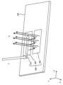
- the projection optical system 50 further includes a polarization reduction plate 310.
- the polarization reduction plate 310 is provided on the first surface side of the projection substrate 100 with respect to the optical waveguide section 200 of the projection substrate 100 with an air layer in between. In this way, the polarization reduction plate 310 is provided apart from the optical waveguide section 200 so as not to affect the optical characteristics of the optical waveguide section 200.
- the polarization reduction plate 310 covers at least a portion of the optical waveguide 200 and reduces light in the polarization direction of the image light leaking from the first surface of the projection substrate 100.
- Polarization reduction plate 310 covers at least a portion of the output diffraction grating in output region 230 . Thereby, the polarization reduction plate 310 can receive image light leaked from the output diffraction grating.
- the polarization reduction plate 310 is provided to reduce the light in the polarization direction of the image light leaked from the first surface of the projection substrate.
- the polarization reduction plate 310 can reduce the intensity of the leaked image light to a level where the image light is not noticeable even if someone else sees the user wearing the glasses-type terminal 10. Further, since the polarization reduction plate 310 transmits light having a polarization direction perpendicular to the polarization direction of the leaked image light, it can transmit external light and allow the user to see it.
- FIG. 7 shows an example in which the polarization reduction plate 310 includes a polarization filter provided facing the first surface of the projection substrate 100.
- a polarizing filter is a polarizing plate, a polarizing film, or the like that attenuates a linearly polarized component of input light in a predetermined direction. It is desirable that the polarization reduction plate 310 be fixed to the frame 110 or the projection substrate 100.
- the polarization reduction plate 310 may include a rotatable polarization filter, and may be capable of adjusting the polarization direction (absorption axis) of the light to be reduced. Further, the polarization reduction plate 310 may be a polarizing film coated on a transparent substrate or the like. Such a polarization reduction plate 310 will be described next.
- FIG. 8 shows a fourth configuration example of the glasses-type terminal 10 according to the present embodiment.
- the operations that are substantially the same as those of the glasses-type terminal 10 according to the present embodiment shown in FIGS. 1 and 7 are given the same reference numerals, and the description thereof will be omitted.
- the appearance of the glasses-type terminal 10 of the fourth configuration example may be almost the same as that of the glasses-type terminal 10 shown in FIG.
- the polarization reduction plate 310 includes a protective substrate 320 and a polarizing film 330.
- the protection substrate 320 is provided facing the first surface of the projection substrate 100.
- the protective substrate 320 is a substrate transparent to at least visible light, such as a glass substrate or a plastic substrate.
- the polarizing film 330 is coated on at least one of the third surface of the protective substrate 320 opposite to the projection substrate 100 and the fourth surface facing the projection substrate 100.
- FIG. 8 shows an example in which a polarizing film 330 is coated on the third surface of the protective substrate 320.
- the polarizing film 330 is a thin film that attenuates the linearly polarized component in a predetermined direction of the input light, similar to a polarizing filter.
- the polarizing film 330 may be coated on part or all of the protective substrate 320.
- the polarization reduction plate 310 having the protective substrate 320 and the polarizing film 330 can also reduce the intensity of image light leaked from the output diffraction grating, similarly to the polarization reduction plate 310 described in FIG. It can transmit external light and be visible to the user.
- the protection substrate 320 is preferably fixed to the frame 110 or the projection substrate 100. Further, the protection substrate 320 may be rotatably provided and configured to be able to adjust the direction of the absorption axis of the polarization reduction plate 310.
- the glasses-type terminal 10 according to the present embodiment described above can reduce leakage of image light that is observed by a user with a simple configuration.
- the transmission axis of the polarization reduction plate 310 is adjustable in the glasses-type terminal 10
- the present invention is not limited to this.
- the glasses-type terminal 10 may be configured to be able to adjust the polarization direction of the image light.
- the projection unit 120 includes a polarization adjustment unit that adjusts the polarization direction of the projection light irradiated onto the incident region 210.
- the polarization adjustment section includes, for example, a wavelength plate that rotates the polarization direction of linearly polarized light.
- the polarization adjustment unit adjusts the polarization direction of the image light leaking from the first surface of the projection substrate 100 so as to substantially match the polarization direction in which the polarization reduction plate 310 reduces the intensity of the light.
- Such a projection section 120 can adjust the polarization direction of the projection light so that the projection light is efficiently guided in the optical waveguide section 200 and leaked light is appropriately reduced by the polarization reduction plate 310.
- the polarization adjustment section may adjust the polarization direction of the projection light so that the polarization direction of the image light leaked from the output diffraction grating becomes horizontal.
- the absorption axis of the polarization reduction plate 310 is made to substantially coincide with the horizontal direction.
- horizontal light is reduced by the polarization reduction plate 310.
- the glasses-type terminal 10 can also function as polarized glasses that reduce reflected light from horizontal surfaces such as water surfaces.
- the projection optical system 50 includes a plurality of projection substrates 100, and a plurality of image lights of different wavelengths are superimposed.
- the image may be viewed by the user.
- the polarization reduction plate 310 is preferably provided on the side of the plurality of projection substrates 100 opposite to the user.
- FIG. 6 shows an example in which the projection optical system 50 includes three projection substrates 100 and one polarization reduction plate 310 provided on the opposite side of the three projection substrates 100 from the user.
- the projection unit 120 may include a polarization adjustment unit that adjusts the polarization direction of at least one projection light among the plurality of projection lights irradiated onto the incident region 210.
- the polarization adjustment unit adjusts the polarization direction of at least one projection light among the plurality of projection lights included in the image light leaking from the first surface of the projection substrate 100, and the polarization reduction plate 310 reduces the intensity of the light.
- the direction of polarization is adjusted to substantially match the direction of polarization.
- the projection unit 120 efficiently guides at least one projection light in the optical waveguide 200 and appropriately reduces leakage light corresponding to the projection light with the polarization reduction plate 310. Polarization direction can be adjusted.
- the projection unit 120 may have a plurality of polarization adjustment units that adjust the polarization directions of the plurality of projection lights in correspondence with the plurality of projection lights irradiated onto the incident region 210.
- the projection unit 120 efficiently guides the plurality of projection lights in the optical waveguide 200 and appropriately reduces leakage light corresponding to the plurality of projection lights in the polarization reduction plate 310. The direction of polarization can be adjusted.
- the optical waveguide section 200 of the projection substrate 100 has an entrance region 210, an intermediate region 220, and an output region 230, but the invention is not limited to this.
- the optical waveguide section 200 only needs to be able to output the projection light incident from the projection section 120 as image light for the user to observe, and the shapes of the incident region 210, intermediate region 220, and output region 230 may be other shapes. Good too.
- the optical waveguide section 200 may have, for example, an entrance region 210 and an output region 230, but no intermediate region 220.
- Eyeglass-type terminal 20
- Input light beam 30
- Output light beam bundle 50
- Projection optical system 100
- Projection substrate 110
- Frame 120
- Projection section 200
- Optical waveguide section 210
- Incident region 212
- First groove section 220 Intermediate region 222
- Second groove section 224
- First divided region 226
- First reflection Region 230
- Output region 232
- Third groove 234 Second divided region 236
- Second reflective region 310
- Polarization reduction plate 330
Landscapes
- Physics & Mathematics (AREA)
- General Physics & Mathematics (AREA)
- Optics & Photonics (AREA)
- Engineering & Computer Science (AREA)
- Multimedia (AREA)
- Signal Processing (AREA)
- Optical Couplings Of Light Guides (AREA)
Priority Applications (6)
| Application Number | Priority Date | Filing Date | Title |
|---|---|---|---|
| PCT/JP2022/030272 WO2024033969A1 (ja) | 2022-08-08 | 2022-08-08 | 投影光学系及び眼鏡型端末 |
| CN202280098778.3A CN119631006A (zh) | 2022-08-08 | 2022-08-08 | 投影光学系统以及眼镜型终端 |
| KR1020257006526A KR20250070038A (ko) | 2022-08-08 | 2022-08-08 | 투영광학계 및 안경형 단말기 |
| JP2024540086A JP7656847B2 (ja) | 2022-08-08 | 2022-08-08 | 眼鏡型端末 |
| TW112128400A TWI882397B (zh) | 2022-08-08 | 2023-07-28 | 眼鏡型終端 |
| US19/046,535 US20250277978A1 (en) | 2022-08-08 | 2025-02-06 | Projection optical system and glasses-type terminal |
Applications Claiming Priority (1)
| Application Number | Priority Date | Filing Date | Title |
|---|---|---|---|
| PCT/JP2022/030272 WO2024033969A1 (ja) | 2022-08-08 | 2022-08-08 | 投影光学系及び眼鏡型端末 |
Related Child Applications (1)
| Application Number | Title | Priority Date | Filing Date |
|---|---|---|---|
| US19/046,535 Continuation US20250277978A1 (en) | 2022-08-08 | 2025-02-06 | Projection optical system and glasses-type terminal |
Publications (1)
| Publication Number | Publication Date |
|---|---|
| WO2024033969A1 true WO2024033969A1 (ja) | 2024-02-15 |
Family
ID=89851142
Family Applications (1)
| Application Number | Title | Priority Date | Filing Date |
|---|---|---|---|
| PCT/JP2022/030272 Ceased WO2024033969A1 (ja) | 2022-08-08 | 2022-08-08 | 投影光学系及び眼鏡型端末 |
Country Status (6)
| Country | Link |
|---|---|
| US (1) | US20250277978A1 (https=) |
| JP (1) | JP7656847B2 (https=) |
| KR (1) | KR20250070038A (https=) |
| CN (1) | CN119631006A (https=) |
| TW (1) | TWI882397B (https=) |
| WO (1) | WO2024033969A1 (https=) |
Cited By (2)
| Publication number | Priority date | Publication date | Assignee | Title |
|---|---|---|---|---|
| CN119045112A (zh) * | 2024-08-26 | 2024-11-29 | 维沃移动通信有限公司 | 导光组件和电子设备 |
| WO2025196868A1 (ja) * | 2024-03-18 | 2025-09-25 | Cellid株式会社 | 投影基板及び眼鏡型端末 |
Citations (4)
| Publication number | Priority date | Publication date | Assignee | Title |
|---|---|---|---|---|
| WO2018012108A1 (ja) * | 2016-07-12 | 2018-01-18 | ソニー株式会社 | 調光装置、画像表示装置及び表示装置 |
| CN210776045U (zh) * | 2019-12-12 | 2020-06-16 | 深圳惠牛科技有限公司 | 一种光波导结构及增强现实设备 |
| JP2021508093A (ja) * | 2018-01-12 | 2021-02-25 | エルジー・ケム・リミテッド | 回折導光板およびこれを含むディスプレイ装置 |
| WO2021106749A1 (ja) * | 2019-11-26 | 2021-06-03 | 富士フイルム株式会社 | 光学部材および画像表示装置 |
Family Cites Families (3)
| Publication number | Priority date | Publication date | Assignee | Title |
|---|---|---|---|---|
| US20160077338A1 (en) * | 2014-09-16 | 2016-03-17 | Steven John Robbins | Compact Projection Light Engine For A Diffractive Waveguide Display |
| JP6694158B2 (ja) | 2016-05-20 | 2020-05-13 | 株式会社リコー | 虚像表示装置及び虚像表示方法 |
| US11774737B2 (en) * | 2019-12-06 | 2023-10-03 | Meta Platforms Technologies, Llc | Folded-beam, low-obliquity beam scanner |
-
2022
- 2022-08-08 WO PCT/JP2022/030272 patent/WO2024033969A1/ja not_active Ceased
- 2022-08-08 KR KR1020257006526A patent/KR20250070038A/ko active Pending
- 2022-08-08 CN CN202280098778.3A patent/CN119631006A/zh active Pending
- 2022-08-08 JP JP2024540086A patent/JP7656847B2/ja active Active
-
2023
- 2023-07-28 TW TW112128400A patent/TWI882397B/zh active
-
2025
- 2025-02-06 US US19/046,535 patent/US20250277978A1/en active Pending
Patent Citations (4)
| Publication number | Priority date | Publication date | Assignee | Title |
|---|---|---|---|---|
| WO2018012108A1 (ja) * | 2016-07-12 | 2018-01-18 | ソニー株式会社 | 調光装置、画像表示装置及び表示装置 |
| JP2021508093A (ja) * | 2018-01-12 | 2021-02-25 | エルジー・ケム・リミテッド | 回折導光板およびこれを含むディスプレイ装置 |
| WO2021106749A1 (ja) * | 2019-11-26 | 2021-06-03 | 富士フイルム株式会社 | 光学部材および画像表示装置 |
| CN210776045U (zh) * | 2019-12-12 | 2020-06-16 | 深圳惠牛科技有限公司 | 一种光波导结构及增强现实设备 |
Cited By (2)
| Publication number | Priority date | Publication date | Assignee | Title |
|---|---|---|---|---|
| WO2025196868A1 (ja) * | 2024-03-18 | 2025-09-25 | Cellid株式会社 | 投影基板及び眼鏡型端末 |
| CN119045112A (zh) * | 2024-08-26 | 2024-11-29 | 维沃移动通信有限公司 | 导光组件和电子设备 |
Also Published As
| Publication number | Publication date |
|---|---|
| CN119631006A (zh) | 2025-03-14 |
| KR20250070038A (ko) | 2025-05-20 |
| JP7656847B2 (ja) | 2025-04-04 |
| TWI882397B (zh) | 2025-05-01 |
| JPWO2024033969A1 (https=) | 2024-02-15 |
| TW202407428A (zh) | 2024-02-16 |
| US20250277978A1 (en) | 2025-09-04 |
Similar Documents
| Publication | Publication Date | Title |
|---|---|---|
| US11402636B2 (en) | Method and system for waveguide projector with wide field of view | |
| US10162181B2 (en) | Display device with optics for brightness uniformity tuning having DOE optically coupled to receive light at central and peripheral regions | |
| US20250277978A1 (en) | Projection optical system and glasses-type terminal | |
| TWI883421B (zh) | 投影基板以及眼鏡型終端 | |
| US12443044B2 (en) | Projection substrate and smart glasses | |
| US20250035936A1 (en) | Projection substrate and method for manufacturing substrate | |
| JP7759040B2 (ja) | 投影光学系及び眼鏡型端末 | |
| KR102661231B1 (ko) | 광학 시스템 및 혼합 현실 설비 | |
| TWI882296B (zh) | 投影基板以及眼鏡型終端 | |
| CN122003633A (zh) | 投影基板以及眼镜型终端 | |
| WO2025215825A1 (ja) | 投影基板及び眼鏡型端末 | |
| WO2025083761A1 (ja) | 投影基板及び眼鏡型端末 | |
| WO2025210838A1 (ja) | 投影基板、回折用基板、眼鏡型端末、及び投影基板の製造方法 | |
| WO2025196868A1 (ja) | 投影基板及び眼鏡型端末 | |
| WO2026028371A1 (ja) | 投影基板、投影基板の製造方法、及び眼鏡型端末 |
Legal Events
| Date | Code | Title | Description |
|---|---|---|---|
| 121 | Ep: the epo has been informed by wipo that ep was designated in this application |
Ref document number: 22954891 Country of ref document: EP Kind code of ref document: A1 |
|
| WWE | Wipo information: entry into national phase |
Ref document number: 2024540086 Country of ref document: JP |
|
| WWE | Wipo information: entry into national phase |
Ref document number: 202280098778.3 Country of ref document: CN |
|
| NENP | Non-entry into the national phase |
Ref country code: DE |
|
| WWP | Wipo information: published in national office |
Ref document number: 202280098778.3 Country of ref document: CN |
|
| 122 | Ep: pct application non-entry in european phase |
Ref document number: 22954891 Country of ref document: EP Kind code of ref document: A1 |