WO2024029349A1 - 情報処理装置、情報処理方法、および記録媒体 - Google Patents
情報処理装置、情報処理方法、および記録媒体 Download PDFInfo
- Publication number
- WO2024029349A1 WO2024029349A1 PCT/JP2023/026535 JP2023026535W WO2024029349A1 WO 2024029349 A1 WO2024029349 A1 WO 2024029349A1 JP 2023026535 W JP2023026535 W JP 2023026535W WO 2024029349 A1 WO2024029349 A1 WO 2024029349A1
- Authority
- WO
- WIPO (PCT)
- Prior art keywords
- image
- learning
- input
- images
- information processing
- Prior art date
- Legal status (The legal status is an assumption and is not a legal conclusion. Google has not performed a legal analysis and makes no representation as to the accuracy of the status listed.)
- Ceased
Links
Images









Classifications
-
- G—PHYSICS
- G06—COMPUTING OR CALCULATING; COUNTING
- G06V—IMAGE OR VIDEO RECOGNITION OR UNDERSTANDING
- G06V10/00—Arrangements for image or video recognition or understanding
- G06V10/70—Arrangements for image or video recognition or understanding using pattern recognition or machine learning
- G06V10/77—Processing image or video features in feature spaces; using data integration or data reduction, e.g. principal component analysis [PCA] or independent component analysis [ICA] or self-organising maps [SOM]; Blind source separation
- G06V10/774—Generating sets of training patterns; Bootstrap methods, e.g. bagging or boosting
-
- G—PHYSICS
- G06—COMPUTING OR CALCULATING; COUNTING
- G06N—COMPUTING ARRANGEMENTS BASED ON SPECIFIC COMPUTATIONAL MODELS
- G06N20/00—Machine learning
-
- G—PHYSICS
- G06—COMPUTING OR CALCULATING; COUNTING
- G06T—IMAGE DATA PROCESSING OR GENERATION, IN GENERAL
- G06T7/00—Image analysis
-
- G—PHYSICS
- G06—COMPUTING OR CALCULATING; COUNTING
- G06V—IMAGE OR VIDEO RECOGNITION OR UNDERSTANDING
- G06V10/00—Arrangements for image or video recognition or understanding
- G06V10/94—Hardware or software architectures specially adapted for image or video understanding
- G06V10/945—User interactive design; Environments; Toolboxes
Definitions
- the present technology relates to an information processing device, an information processing method, and a recording medium, and particularly relates to an information processing device, an information processing method, and a recording medium that can easily acquire images suitable for AI use cases. .
- Patent Document 1 describes a data management system that classifies raw data collected from data sources and generates datasets.
- Patent Document 1 uses methods such as photographing actual scenery, searching for appropriate images from images published on the Internet, and using datasets published on websites. Users themselves need to collect large amounts of images for AI training.
- This technology was developed in light of this situation, and makes it possible to easily obtain images suitable for AI use cases.
- An information processing device selects a learning image to be used for learning a learning model from among a group of images held in advance, according to a use case of a learning model that inputs an image. Department.
- an information processing device selects a learning model that is used for learning a learning model from among a group of images held in advance according to a use case of a learning model that uses images as input. Select an image.
- a recording medium performs a process of selecting a learning image to be used for learning a learning model from among a group of images stored in advance, according to a use case of a learning model that inputs images. Record the program to be executed.
- a learning image to be used for learning the learning model is selected from among a group of images held in advance, according to a use case of a learning model that inputs images.
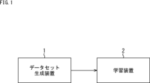
- FIG. 1 is a diagram showing a configuration example of an AI learning system according to an embodiment of the present technology.
- FIG. 2 is a diagram illustrating a flow in which a dataset generation device generates a dataset.
- FIG. 3 is a diagram illustrating an example of an input interface for each setting and an example of information input for each setting. 3 is a diagram illustrating details of data set generation performed in step S5 of FIG. 2.
- FIG. 3 is a diagram illustrating an example of a table used to select an image suitable for a use case. It is a figure explaining the flow after a data set is generated.
- FIG. 3 is a diagram illustrating an example of an output interface displayed on a GUI and an example of displayed information.
- FIG. 3 is a diagram showing a first display example of an input GUI.
- FIG. 7 is a diagram showing a second display example of the input GUI.
- FIG. 7 is a diagram showing a third display example of the input GUI.
- FIG. 7 is a diagram showing a fourth display example of the input GUI.
- FIG. 7 is a diagram showing a fifth display example of the input GUI.
- FIG. 3 is a diagram showing a first display example of an output GUI.
- FIG. 6 is a diagram illustrating a display example of a learning image list screen.
- FIG. 7 is a diagram showing a second display example of the output GUI.
- FIG. 7 is a diagram showing a third display example of the output GUI.
- FIG. 7 is a diagram showing a fourth display example of the output GUI.
- FIG. 2 is a block diagram showing a configuration example of a data set generation device.
- FIG. 2 is a block diagram showing a configuration example of a data set generation device.
- FIG. 3 is a diagram showing an example of camera simulation.
- FIG. 3 is a diagram showing an example of image output by an AI engine. It is a flowchart explaining the processing performed by the data set generation device.
- FIG. 7 is a diagram showing another display example of the input GUI.
- FIG. 2 is a block diagram showing an example of the hardware configuration of a computer.
- FIG. 1 is a diagram illustrating a configuration example of an AI learning system according to an embodiment of the present technology.
- the AI learning system is composed of a dataset generation device 1 and a learning device 2.
- the dataset generation device 1 is an information processing device that displays a GUI (Graphical User Interface) for inputting AI use cases, etc., and generates a dataset composed of multiple learning images according to the use case.
- a training image is an image used for AI learning.
- the dataset is generated, for example, by selecting an image suitable for a use case as a learning image from a group of images held in advance by the dataset generation device 1.
- images generated using CG and images taken in real life, and metadata corresponding to each image are registered in a database.
- the metadata corresponding to each image includes information indicating the type of subject and background in the image, a depth map corresponding to the image, a segmentation result for the image, and the like.
- Images registered in the database may be composed of still images or moving images.
- the dataset generation device 1 supplies the generated dataset to the learning device 2.
- the learning device 2 performs learning using the dataset supplied from the dataset generating device 1, and generates an AI engine including an AI (learning model).
- the learning device 2 may perform AI relearning using the dataset supplied from the dataset generating device 1.
- the learning device 2 may be configured to include the dataset generating device 1. In this case, when the user inputs a use case using the GUI, the learning device 2 can generate a data set and perform AI learning.
- step S1 the user uses the GUI displayed by the dataset generation device 1 to input various settings for generating the dataset.
- the dataset generation device 1 receives input of common settings, use cases, and user settings via the GUI.
- step S5 the dataset generation device 1 generates a dataset.
- images according to the common settings, use cases, and user settings input via the GUI are selected as training images from among the images registered in the database, and the image dataset and metadata are A set is generated.
- the image data set is a data set made up of a plurality of learning images
- the metadata set is a data set made up of metadata corresponding to each of the plurality of learning images. Details of data set generation will be described later with reference to FIG. 4.
- step S6 the dataset generation device 1 displays a preview of the learning image on the GUI.
- step S7 the user views the preview display of the learning images on the GUI and determines whether the image dataset generated by the dataset generation device 1 is a desired dataset.
- step S7 If it is determined in step S7 that the image data set is not the desired data set, the process returns to step S1, and the user further inputs or changes settings using the GUI. For example, the user can input additional images, which are images that the user wants to add to the image dataset, or input a 3DCG scene.
- step S8 the dataset generation device 1 receives input of additional images via the GUI.
- additional images For example, an option indicating whether to replace the additional image with an image from the database is input together with the additional image.
- step S9 the dataset generation device 1 determines whether to replace the additional image with an image from the database based on the option.
- the dataset generation device 1 replaces the image group held in the database based on the additional image with the following: Select images to add to the image dataset. Specifically, the dataset generation device 1 searches for an image similar to the additional image (similar image) from among the image group held in the database and adds it to the image dataset.
- step S8 if it is determined in step S8 that the additional image is not replaced with an image from the database, the dataset generation device 1 adds the additional image as is to the image dataset, and displays a preview of the learning image in step S6.
- the dataset generation device 1 receives input of a 3DCG scene via the GUI.
- a 3DCG scene file including a CG (Computer Graphics) 3D model (CG model) and rendering settings are input to the dataset generation device 1.
- CG model refers to a model of a three-dimensional object and surrounding environment formed in a virtual space.
- step S11 the dataset generation device 1 generates a rendered image by performing rendering using the 3DCG scene file, and adds the rendered image to the image dataset. After that, in step S6, the dataset generation device 1 displays a preview of the learning image.
- the user can input common settings, use cases, user settings, additional images, and 3DCG scenes in any order.
- the user looks at the training image preview display that is updated each time each setting is entered as described above, and if the user determines that the image dataset is the desired dataset, clicks the camera simulation execution button on the GUI. Press down. The flow after pressing the camera simulation execution button will be described later with reference to FIG.
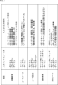
- FIG. 3 is a diagram showing an example of an input interface for each setting and an example of information input for each setting.
- Common settings are input using an input interface such as a text box, pull-down menu, or icon.
- Common settings input includes information about the camera for camera simulation (camera information), the number of learning images to be output, the resolution of the output learning images, the format of the output images, and whether live-action images or CG images are to be used as learning images.
- the user inputs information such as which image is desired and whether to perform augmentation.
- Use case input is performed using input interfaces such as text boxes, pull-down menus, and icons.
- input interfaces such as text boxes, pull-down menus, and icons.
- the type of use case such as person recognition or noise reduction, is input.
- User settings are entered using input interfaces such as text boxes, pull-down menus, icons, and slider bars.
- conditions desired by the user for the learning images are input, such as metadata such as the type of subject and background, and image statistics such as brightness and frequency.
- Inputting additional images is performed using input interfaces such as drag and drop, text boxes, pull-down menus, and icons.
- input interfaces such as drag and drop, text boxes, pull-down menus, and icons.
- 3DCG scenes are input using input interfaces such as drag and drop, text boxes, pull-down menus, and icons.
- input interfaces such as drag and drop, text boxes, pull-down menus, and icons.
- the 3DCG scene file, renderer settings, and whether to perform augmentation by moving the virtual camera or moving the subject are input.
- one of three processes from steps S31 to S33 is performed depending on the type of settings input via the GUI. It is assumed that common settings are commonly input in each of the three processes of steps S31 to S33.
- the dataset generation device 1 When the use case and common settings are input, in step S31, the dataset generation device 1 generates an image suitable for the use case from among the image group registered in the database, for example, based on the input common settings. Select as many images as learning images. For example, the dataset generation device 1 selects an image suitable for a use case based on a table in which each image registered in a database, a score for the use case, metadata, statistics, etc. are registered. The score for a use case indicates the degree to which each image registered in the database is suitable as a training image for AI used in a certain use case.
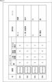
- FIG. 5 is a diagram showing an example of a table used to select an image suitable for a use case.
- the ID of each image registered in the database, image file, score for the use case, subject, and background (scene) are registered in the table.
- use cases include NR (Noise Reduction), person recognition, object recognition, and depth estimation.
- NR Noise Reduction
- person recognition person recognition
- object recognition object recognition
- depth estimation depth estimation
- the image assigned ID 001 is given a score of 8 for NR, a score of 7 for person recognition, a score of 4 for object recognition, and a score of 6 for depth estimation.
- the image assigned ID 001 shows a dog and a person as the subject, and that the room is shown as the background.
- the image assigned ID 002 is given a score of 5 for NR, a score of 6 for person recognition, a score of 5 for object recognition, and a score of 7 for depth estimation.
- the image assigned ID 002 includes people, cars, and bicycles as subjects, and that the image shows the city as the background.
- the image assigned ID 003 is given a score of 4 for NR, a score of 6 for person recognition, a score of 1 for object recognition, and a score of 3 for depth estimation.
- the image assigned ID 003 includes a person as the subject, and that the image includes a river as the background.
- the image assigned ID 004 is given a score of 3 for NR, a score of 2 for person recognition, a score of 4 for object recognition, and a score of 5 for depth estimation.
- the image assigned the ID 004 shows a car and a signboard as the subject, and that it shows the forest as the background.
- the dataset generation device 1 selects, as learning images, the number of images input in the common setting, from among the images registered in the database, in descending order of the scores for the use case input via the GUI. .
- the dataset generation device 1 selects a learning image by, for example, referring to metadata registered in the database. Specifically, the dataset generation device 1 inputs images corresponding to the user's wishes input in the user settings based on the above-mentioned table from among the image group registered in the database, using common settings. The selected number of images are selected as learning images.
- the dataset generation device 1 searches for an image similar to the additional image from among the image groups registered in the database, and adds it to the image dataset. to add. For example, if the number of training images included in the dataset exceeds the number entered in the common settings due to the addition of images similar to the additional images, the number of training images will be changed to the number entered in the common settings. Some of the images originally included in the dataset are removed from the dataset so that the number of images is equal to the number of images originally included in the dataset. For example, images to be excluded from the dataset may be determined based on the score of each learning image for the use case, such as excluding images from the dataset in descending order of the score for the use case.
- step S41 the dataset generation device 1 receives a press of the camera simulation execution button via the GUI.
- the dataset generation device 1 When the camera simulation execution button is pressed, the dataset generation device 1 performs steps S42 and S46, which are shown surrounded by broken lines.
- step S42 the dataset generation device 1 executes camera simulation.
- images included in an image dataset, additional images, and rendered images are processed based on camera information for camera simulation to generate a simulated image dataset.
- the data set generation device 1 generates, for example, an image that reproduces an image taken by the camera indicated by the camera information, through processing processing based on the camera information.
- the images included in the simulated image data set are images included in the image data set, additional images, and rendered images, including noise generated on the image due to shooting with the camera to be reproduced.
- the camera to be reproduced in the camera simulation is, for example, a camera that captures an image that is input to the AI generated by the learning device 2.
- the images, additional images, and rendered images included in the image data set to be processed are ideal images.
- the ideal image is an image that does not contain noise or the like.
- step S43 the dataset generation device 1 stores the simulated image dataset.
- step S44 the dataset generation device 1 performs image analysis on the simulated image dataset and obtains statistics for the entire simulated image dataset.
- step S45 the dataset generation device 1 stores the statistics of the simulated image dataset.
- step S46 the dataset generation device 1 performs metadata processing on the additional image and the rendered image. Specifically, the dataset generation device 1 performs object recognition on the additional image and the rendered image, and acquires metadata corresponding to each of the additional image and the rendered image.
- step S47 the dataset generation device 1 stores the metadata set generated in the dataset generation in step S5 and the metadata acquired in step S46 as one metadata set.
- step S48 the dataset generation device 1 displays the output dataset on the GUI.
- the output dataset includes a simulated image dataset, statistics for the simulated image dataset, and a metadata set.
- step S49 the user looks at the display of the output data set on the GUI and determines whether the output data set is the desired data set.
- step S49 If it is determined in step S49 that the output data set is not the desired data set, the process returns to step S1 in FIG. 2, and the user further inputs or changes settings using the GUI.
- step S49 if it is determined in step S49 that the output data set is the desired data set, the user operates the learning device 2 to perform AI learning in step S50.
- the output dataset output from the dataset generation device 1 via the GUI is used for AI learning.
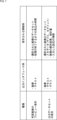
- FIG. 7 is a diagram showing an example of an output interface displayed on the GUI and an example of displayed information.
- the preview display of the learning image is performed using an output interface such as an image or text.
- the dataset including the image selected as the learning image, the estimated time until the camera simulation process is completed, etc. are displayed.
- the display of the output data set is performed using an output interface such as images, text, and graphs.
- the output dataset display includes the dataset containing the images selected as training images (simulated images), the metadata corresponding to each training image, the analysis results of each training image, the statistics of the entire image dataset, and the input Information about the settings that have been made will be displayed.
- the GUI displayed by the data set generation device 1 will be described with reference to FIGS. 8 to 17.
- the dataset generation device 1 an input GUI for the user to input use cases and the like, and an output GUI for the user to check the output dataset are displayed.
- the input GUI is displayed before the camera simulation is performed, and the output GUI is displayed after the camera simulation is performed and before the output data set is output to the learning device 2.
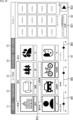
- FIG. 8 is a diagram showing a first display example of the input GUI.
- the input GUI is composed of an input area A1 and a preview area A2.
- a screen including input means for inputting various settings is displayed, and in the preview area A2, a preview of the learning image is displayed.
- a screen for inputting any of common settings, use cases, user settings, additional images, and 3DCG scenes is displayed in input area A1.
- the tab T1 is shown in white, indicating that the tab T1 among the tabs T1 to T5 is selected.
- a common setting input screen which is a screen including input means for inputting common settings, is displayed in the input area A1.
- An input box B1 for inputting the number of learning images to be output is displayed at the upper left of the common setting input screen. In the example of FIG. 8, it is input that 1000 learning images are to be output.
- an input box B2 is displayed for inputting information regarding the image sensor provided in the camera to be reproduced in the camera simulation.
- information regarding the image sensor for example, the model number of the image sensor and the characteristics of the image sensor are input.
- the data set generation device 1 can simulate noise that occurs when an image is acquired by the image sensor. In the example of FIG. 8, the model number "IMX290" is input.
- an input box B3 is displayed for inputting information regarding the lens provided in the camera to be reproduced in the camera simulation.
- the type of lens is input as the information regarding the lens.
- the type of "wide-angle lens" is input.
- a check box C1 for selecting whether to input detailed settings is displayed below the input box B3. If you select to perform detailed settings, for example, an input method for inputting PSF (Point Spread Function) and distortion data measured for the camera to be reproduced will be displayed on the common settings input screen. .
- PSF Point Spread Function
- the above-mentioned information regarding the image sensor, information regarding the lens, and detailed settings are included in the camera information for camera simulation.
- Information regarding camera settings and photographing conditions may be input as the camera information.
- An input box B4 for inputting augmentation settings is displayed below the check box C1.
- the augmentation settings what is to be changed by the augmentation, such as changing the amount of noise or brightness, is input.
- the input is to create a dark image and a bright image by changing the brightness of the image. If there is no need to perform augmentation, the user may, for example, not input settings for augmentation or input a setting not to perform augmentation.
- An input box B5 for inputting the format (data format) of the learning image to be output is displayed below the input box B4.
- the format of ".exr" is input.
- An input box B6 for inputting the resolution of the learning image to be output is displayed below the input box B5.
- the input is to output a learning image with a width of 4000 pixels and a height of 3000 pixels.
- FIG. 9 is a diagram showing a second display example of the input GUI.
- tab T2 is shown in white, indicating that tab T2 is selected from tabs T1 to T5.
- a use case input screen which is a screen including input means for inputting a use case, is displayed in the input area A1.
- An input box B11 for inputting a use case is displayed at the upper left of the use case input screen.
- the AI use case is noise reduction.
- a list of possible use cases is displayed below the input box B11 using icons and buttons.
- an icon I1 and button B12 indicating noise reduction an icon I2 and button B13 indicating person recognition, and an icon I3 and button B14 indicating object recognition are displayed. Since noise reduction has been input as a use case in the input box B11, the icon I1 and button B12 indicating noise reduction are highlighted compared to other icons and buttons, as shown surrounded by thick lines in FIG. be done.
- the user can input the purpose of using AI (use case) by inputting using the input box B11 or by pressing an icon or box.
- AI use case
- the input use case is reflected in the display of icons and buttons
- the input use case is reflected in the display of icons and buttons. It is also reflected in the display of input box B11.
- a preview display is performed in the preview area A2 that displays a list of learning images selected based on the common settings and use cases.
- thumbnail images representing each learning image are displayed side by side.
- 4 ⁇ 3 (vertical ⁇ horizontal) thumbnail images are displayed in a tiled arrangement.
- the dataset generation device 1 switches the thumbnail images displayed in the preview area A2 by accepting a predetermined operation by the user.
- information regarding the number of selected learning images is displayed as white and black circles shown below the thumbnail image.
- An input box B21 for presenting the estimated time until the camera simulation process is completed is displayed at the lower left of the preview area A2. In the example of FIG. 9, it is displayed that the estimated time until the camera simulation process is completed is one hour.
- a camera simulation execution button B22 is displayed at the bottom right of the preview area A2.
- a preview of the simulated image may be displayed in the preview area A2.
- one predetermined image that has been processed based on the input camera information is displayed on the right side of the thumbnail image of the learning image.
- the predetermined one image may be one of the learning images included in the image data set, or may be one predetermined image.
- the user can check whether the processing performed on the image in the camera simulation is the desired processing by viewing the preview display of the simulated image.
- FIG. 10 is a diagram showing a third display example of the input GUI.
- tab T3 is shown in white, indicating that tab T3 is selected from tabs T1 to T5.
- a user setting input screen which is a screen including input means for inputting user settings, is displayed in the input area A1.
- An input box B31 for inputting the type of background of the learning image is displayed at the top of the user setting input screen. In the example of FIG. 10, it is input that a learning image showing the city as a background is to be output.
- a list of possible backgrounds is displayed below the input box B31 using icons and buttons.
- icons and buttons representing each of the city, room, forest, and river are displayed. Since the city has been entered as the background in the input box B31, the icons and buttons representing the city are displayed with emphasis compared to other icons and buttons, as shown surrounded by thick lines in FIG.
- the user can input the type of background desired as the background of the learning image by inputting using the input box B31 or by pressing an icon or button.
- the input background type is also reflected in the display of icons and buttons, and when the type of background is input using the icon or button, the input The type of background is also reflected in the display of input box B31.
- An input box B32 for inputting the type of subject of the learning image is displayed below the button indicating the type of background. In the example of FIG. 10, it is input that a learning image showing a person and a bicycle as subjects is to be output.
- a list of possible subjects is displayed below the input box B32 using icons and buttons.
- icons and buttons representing each of a person, a car, a bicycle, and a dog are displayed. Since a person and a bicycle are input as subjects in the input box B32, the icons and buttons representing the person and bicycle are emphasized compared to other icons and buttons, as shown surrounded by thick lines in FIG. Is displayed.
- the user can input the type of subject desired as the subject of the learning image by inputting using the input box B32 or by pressing an icon or button.
- the input type of subject is also reflected in the display of icons and buttons, and when the type of subject is input using the icon or button, the input The type of subject is also reflected in the display of input box B32.
- a slider bar SB1 is displayed for inputting the brightness of the image.
- the user can adjust the brightness of the learning image by moving the slider on the slider bar SB1.
- the dataset generation device 1 for example, selects as the learning image an image darker than the image originally selected as the learning image. .
- the data set generation device 1 can also change the brightness of the learning image without changing the learning image according to the user's operation.
- a slider bar SB2 for inputting the image frequency is displayed at the bottom center of the user setting input screen.
- the user can adjust the frequency of the learning image by moving the slider on the slider bar SB2.
- the dataset generation device 1 when the slider on the slider bar SB2 is moved to the left by the user, the dataset generation device 1 generates an image in which the pattern of the subject is flatter than the image originally selected as the learning image. (e.g., an image whose color does not change much) as a training image.
- the data set generation device 1 can also change the frequency of the learning image without changing the learning image according to the user's operation.
- a slider bar SB3 for inputting the image contrast is displayed.
- the user can adjust the contrast of the learning image by moving the slider on the slider bar SB3.
- the dataset generation device 1 for example, selects an image with lower contrast as the learning image than the image originally selected as the learning image. select.
- the data set generation device 1 can also change the contrast of the learning image without changing the learning image in response to a user's operation.
- FIG. 11 is a diagram showing a fourth display example of the input GUI.
- the tab T4 is shown in white, indicating that the tab T4 is selected from among the tabs T1 to T5.
- an additional image input screen that is a screen including input means for inputting additional images is displayed in the input area A1.
- An input box B41 for inputting an additional image is displayed at the upper left of the additional image input screen.
- the path of the additional image is input into the input box B41.
- the path "C: ⁇ Users ⁇ Pictures ⁇ dog.png" is input.
- the additional images may be composed of still images or moving images.
- a check box C11 is displayed below the input box B41 for selecting whether or not to search for an image similar to the additional image from the database.
- the dataset generation device 1 searches for a similar image to be added from among the image group registered in the database, and adds the similar image to the image dataset.
- a list of learning images including the additional image or images similar to the additional image is displayed in the preview area A2.
- FIG. 12 is a diagram showing a fifth display example of the input GUI.
- tab T5 is shown in white, indicating that tab T5 is selected from tabs T1 to T5.
- a 3DCG scene input screen which is a screen including input means for inputting a 3DCG scene, is displayed in the input area A1.
- An input box B51 for inputting a 3DCG scene file is displayed at the upper left of the 3DCG scene input screen. For example, a path of a 3DCG scene file is input into the input box B51. In the example of FIG. 12, the path "C: ⁇ Users ⁇ Documents ⁇ animal.max" is input.
- an input box B52 is displayed for inputting the renderer used for rendering the 3DCG scene.
- the renderer "S-Render" is input.
- an input box B53 is displayed for inputting a virtual camera that will be the viewpoint of the rendered image among the virtual cameras arranged in the virtual space.
- a virtual camera that will be the viewpoint of the rendered image among the virtual cameras arranged in the virtual space.
- An input box B54 for inputting augmentation settings is displayed below the input box B53.
- the augmentation settings what is to be changed by the augmentation, such as rotating the virtual camera, is input. In the example of FIG. 12, it is input that a plurality of images are created by rotating a (virtual) camera during rendering. If there is no need to perform augmentation, the user may, for example, not input settings for augmentation or input a setting not to perform augmentation.
- a list of learning images including rendered images generated based on the 3DCG scene file is displayed in the preview area A2.
- the rendered image may be composed of a still image or a moving image.
- the output GUI is displayed, for example, when the camera simulation execution button B22 is pressed on the input GUI and the camera simulation processing is completed.
- FIG. 13 is a diagram showing a first display example of the output GUI.
- the output GUI is composed of an output data set display area A11.
- the output data set is displayed.
- tabs T11 to T14 are displayed above the output data set display area A11.
- you can check the list of simulated learning images, details of the simulated learning images, statistics (analysis results) of the simulated image dataset, and output settings. is displayed in the output data set display area A11.
- the tab T11 is shown in white, indicating that the tab T11 among the tabs T11 to T14 is selected.
- a list of simulated learning images is displayed in the output dataset display area A11.
- a list of simulated learning images is displayed at the top of the output dataset display area A11. Specifically, thumbnail images representing simulated learning images are displayed side by side. In the example of FIG. 13, a combination of three thumbnail images arranged in the depth direction is displayed arranged in the horizontal direction. For example, a plurality of images that are similar to each other, such as images with the same type of subject or images with similar metadata and statistics (brightness, frequency, etc.), are displayed side by side in the depth direction.
- An input box B61 for inputting the type of metadata or the type of statistics (analysis data) of the learning image that the user wants to confirm is displayed below the thumbnail image showing the learning image. In the example of FIG. 13, it is input that the user wants to check the depth map.
- buttons each indicating a depth map and a segmentation result as metadata, and a frequency, color distribution, and brightness distribution as statistics are displayed. Since the depth map has been input in the input box B61, the icon and button indicating the depth map are highlighted compared to other icons and buttons, as shown surrounded by thick lines in FIG. 13.
- the user can input the type of metadata or the type of statistics that he/she wants to confirm by inputting using the input box B61 or by pressing an icon or button.
- the type of metadata or statistics is also reflected in the display of icons and buttons.
- the type of metadata or statistics is also reflected in the display of the input box B61.
- buttons indicating the types of metadata and statistics a list of the types of metadata and statistics entered using the input box B61 etc. is displayed. Specifically, images showing the types of metadata and statistics input using the input box B61 or the like are displayed side by side. The positions of the images showing metadata and statistics correspond to the positions of simulated learning images displayed at the top of the output data set display area A11. For example, an image indicating metadata corresponding to a learning image displayed on the first front side from the left in the upper part of the output dataset display area A11 is displayed on the first front side from the left in the lower part of the output dataset display area A11. will be displayed.
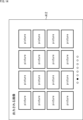
- a learning image list screen A12 shown in FIG. 14 is displayed as a pop-up, for example.
- a list of simulated learning images is displayed on the learning image list screen A12.
- thumbnail images representing simulated learning images are displayed in a tiled manner.
- 4 ⁇ 4 (vertical ⁇ horizontal) thumbnail images are displayed side by side.
- the dataset generation device 1 switches the thumbnail images displayed on the learning image list screen A12 by accepting a predetermined operation by the user.
- the learning image list screen A12 in FIG. 14 information regarding the number of simulated learning images is displayed as white and black circles shown below the thumbnail image.
- FIG. 15 is a diagram showing a second display example of the output GUI.
- the tab T12 is shown in white, indicating that the tab T12 is selected from among the tabs T11 to T14. In this case, details of the simulated learning image are displayed in the output data set display area A11.
- an input box B71 is displayed for inputting the type of metadata or the type of statistics that the user wants to confirm.
- it is input that the user wants to check the depth map, segmentation, frequency, color distribution, and brightness distribution.
- buttons On the right side of the input box B71, a list of displayable metadata and statistics is displayed using icons and buttons.
- icons and buttons each indicating a depth map, segmentation, frequency, color distribution, and brightness distribution are displayed. Since the depth map, segmentation, frequency, color distribution, and brightness distribution are input in the input box B71, the icons and buttons indicating the depth map, segmentation, frequency, color distribution, and brightness distribution are shown as thick lines in FIG. It is highlighted and displayed as shown in the box.
- the user can input the type of metadata or the type of statistics that he/she wishes to confirm by inputting using the input box B71 or by pressing an icon or button.
- the type of metadata or statistics is also reflected in the display of icons and buttons.
- the type of metadata or statistics is also reflected in the display of the input box B71.
- a table is displayed in which images indicating the type of metadata input using the input box B71 or the like and graphs indicating statistics are registered in association with learning images.
- the ID of the learning image the thumbnail image of the learning image, the depth map, the image showing the segmentation result, the graph showing the frequency, the graph showing the color distribution, and the brightness histogram are displayed in a list.
- the ID of the learning image is not the ID assigned to each image in the database, but the ID newly assigned to the image selected as the learning image.
- FIG. 16 is a diagram showing a third display example of the output GUI.
- tab T13 is shown in white, indicating that tab T13 is selected from tabs T11 to T14.
- the statistics (analytical data) of the entire simulated image data set are displayed in the output data set display area A11.
- an input box B81 is displayed for inputting the type of statistics for the entire image dataset that the user wants to confirm.
- it is input that the user wants to check the color distribution and brightness distribution.
- buttons On the lower left side of the input box B81, a list of displayable statistics is displayed using icons and buttons.
- icons and buttons each indicating frequency, color distribution, and brightness distribution are displayed. Since the color distribution and brightness distribution have been input in the input box B81, the icons and buttons indicating the color distribution and brightness distribution are emphasized more than other icons and buttons, as shown surrounded by thick lines in FIG. will be displayed.
- the user can input the type of statistics he or she wants to check by using the input box B81 or by pressing an icon or button.
- the input type of statistics is reflected in the display of icons and buttons, and when the type of statistics is input using the icons and buttons, The type of statistics input is also reflected in the display of input box B81.
- a graph showing the statistical amount of the type input using the input box B81 or the like is displayed.
- a graph showing the color distribution of a plurality of learning images included in the simulated image data set and a graph showing the brightness distribution of the plurality of learning images are displayed.
- a table indicating the types of subjects and backgrounds (scenes) of each learning image is displayed.
- the type of subject of each learning image is shown in three granularity: large items, medium items, and small items.
- the subject of the learning image assigned ID 001 is an animal in the large category, a dog in the medium category, and a papillon in the small category.
- the subject of the learning image assigned ID 002 is a vehicle in the major category, and a car in the medium category.
- a box B82 is displayed to visually indicate the distribution of types of subjects and backgrounds in the image dataset.
- the size of the text indicating the subject is changed and displayed, depending on the number of learning images in which the same subject is captured, for example.
- the larger the number of learning images in which the same subject appears the larger the size of the character indicating the subject is displayed.
- the user can also press any one of the large item, medium item, and small item in the table at the bottom left of the output data set display area A11.
- the data set generation device 1 displays in box B82 according to the number of learning images that include animals, vehicles, etc., and when the middle item part of the table is pressed. , a box B82 is displayed in accordance with the number of learning images in which dogs, cars, etc. appear. In this way, the user can specify the granularity of the type of subject displayed in box B82 by pressing any one of the large item, medium item, and small item in the table.
- the user can confirm whether the output data set is the desired data set.
- the user inputs output settings using the output GUI described with reference to FIG.
- FIG. 17 is a diagram showing a fourth display example of the output GUI.
- the tab T14 is shown in white, indicating that the tab T14 is selected from among the tabs T11 to T14.
- input means for inputting output settings is displayed in the output data set display area A11.
- an input box B91 is displayed for inputting the type of statistics (analysis data) that the user wants to include in the output dataset.
- the input is to output an output data set including data indicating color distribution and brightness distribution.
- buttons On the lower left side of the input box B91, a list of statistics that can be output is displayed using icons and buttons.
- icons and buttons each indicating frequency, color distribution, and brightness distribution are displayed. Since the color distribution and brightness distribution have been input in the input box B91, the icons and buttons indicating the color distribution and brightness distribution are emphasized more than other icons and buttons, as shown surrounded by thick lines in FIG. will be displayed.
- the user can input the type of statistics to be output by inputting using the input box B91 or by pressing an icon or button.
- the input type of statistics is also reflected in the display of icons and buttons, and when the type of statistics is input using the icons and buttons, The type of statistics input is also reflected in the display of input box B91.
- the statistics to be output may be the statistics of each learning image, or the statistics of the entire image data set.
- an input box B92 is displayed for the user to input the type of metadata that he or she wants to include in the output data set.
- the depth map is to be output as a metadata set.
- a list of metadata that can be output is displayed using icons and buttons.
- icons and buttons each indicating a depth map and a segmentation result are displayed. Since the depth map has been input in the input box B92, the icon and button indicating the depth map are displayed more emphasized than other icons and buttons, as shown surrounded by thick lines in FIG. 17.
- the user can input the type of metadata to be output by inputting using the input box B92 or by pressing an icon or button.
- the input type of metadata is also reflected in the display of icons and buttons, and when the type of metadata is input using the icon or button, The type of metadata input is also reflected in the display of input box B92.
- An input box B93 for inputting the path of the folder to which the output data set is output is displayed below the button indicating the type of metadata.
- the path "C: ⁇ Users ⁇ Documents" is input.
- the dataset generation device 1 After output settings are input using the output GUI described with reference to FIG. 17, for example, when a predetermined operation is accepted, the dataset generation device 1 outputs an output dataset.
- the input box is a pull-down menu that allows you to select a desired menu, a text box that allows you to enter text, or a box that allows you to select a desired menu or enter text. This is achieved using a combo box, etc. that can do this.
- the user only needs to input an AI use case using the input GUI and output GUI displayed by the dataset generation device 1, and the user can select a Learning images can be obtained. Users will be able to easily obtain training images suitable for AI learning with simple operations, without having to actually take pictures or search for images publicly available on the Internet.
- the dataset generation device 1 when only images that can be used without a license are registered in the database, the user can acquire a large amount of learning images without worrying about the license.
- FIG. 18 is a block diagram showing an example of the configuration of the dataset generation device 1.
- the dataset generation device 1 includes an input/output I/F 11, an input information acquisition section 12, a dataset generation section 13, a dataset database 14, a rendering section 15, a camera simulation execution section 16, and an image analysis section. 17, a metadata processing section 18, an output data set storage section 19, a display control section 20, and a display section 21.
- the input/output I/F 11 is an interface for inputting data to the dataset generation device 1 and outputting data from the dataset generation device 1.
- the data set generation device 1 may include separate input I/F and output I/F.
- the input/output I/F 11 detects the user's operation on the input GUI or the output GUI, and supplies information indicating the operation contents to the input information acquisition unit 12. Further, the input/output I/F 11 acquires the output data set from the output data set storage unit 19 via a path not shown, and outputs it to the learning device 2.
- the input information acquisition unit 12 acquires information on various settings input by the user based on the information supplied from the input/output I/F 11.
- the input information acquisition unit 12 supplies information regarding common settings, use cases, user settings, and additional images to the dataset generation unit 13.
- the input information acquisition unit 12 supplies information regarding the 3DCG scene to the rendering unit 15. When not searching for an image similar to the additional image, the input information acquisition unit 12 supplies the additional image to the camera simulation execution unit 16 and the metadata processing unit 18.
- the dataset generation unit 13 selects learning images from the image group registered in the dataset database 14 based on the information supplied from the input information acquisition unit 12, and generates an image dataset.
- the dataset generation unit 13 functions as a selection unit that selects learning images from a group of images registered in the dataset database 14. Further, the dataset generation unit 13 acquires metadata corresponding to the selected learning image from the dataset database 14 and generates a metadata set.
- the dataset generation unit 13 searches for an image similar to the additional image from among the image group registered in the dataset database 14, and adds it to the image dataset.
- the dataset generation unit 13 supplies the generated image dataset to the camera simulation execution unit 16 and supplies the metadata set to the output dataset storage unit 19.
- the dataset database 14 is registered in advance with images generated using CG, images shot with live action, and metadata and statistics corresponding to each image.
- the rendering unit 15 performs rendering based on the information regarding the 3DCG scene supplied from the input information acquisition unit 12, and generates a rendered image.
- the rendering unit 15 supplies the rendered image to the camera simulation execution unit 16 and the metadata processing unit 18.
- the camera simulation execution unit 16 uses the additional images supplied from the input information acquisition unit 12, each learning image included in the image dataset supplied from the dataset generation unit 13, and the rendered image supplied from the rendering unit 15. Perform camera simulation on the image to generate a simulated image dataset.
- the camera simulation execution unit 16 functions as a processing unit that performs processing based on camera information on additional images, learning images included in the image dataset, and rendered images.
- FIG. 19 is a diagram showing an example of camera simulation.
- the camera simulation execution unit 16 generates a degraded image by adding to the ideal image the degradation and noise that occur on the image due to photography by the camera to be reproduced.
- the camera simulation execution unit 16 performs deterioration by applying a model that convolves the deterioration factor K with the ideal image I and adds noise n, as shown in the following equation (1), for example. Generate image I'.
- AI estimates the degradation factors and noise contained in degraded images.
- arrow #1 in Figure 20 when an AI engine that includes AI receives a photographed image containing the same degradation and noise as the degradation and noise contained in the degraded image used during learning, the AI engine outputs a high-quality reconstructed image that is close to the ideal image, as shown by arrow #2.
- the camera simulation execution unit 16 generates a degraded image that includes the degradation and noise that occurs on the image due to photography by the camera that is the target of reproduction, and the AI that receives the captured image that is captured by the camera that is the target of reproduction as input.
- An image dataset including degraded images suitable for learning can be generated.
- the camera simulation execution unit 16 may generate the degraded image by applying a model corresponding to the lens system of the camera to be reproduced and a model corresponding to the sensor system to the ideal image. .
- the model corresponding to the lens system may be a model that adds deterioration such as blur, distortion, shading, flare, ghost, etc. caused by aberration, transmittance, optical filter, stray light, etc. in the lens to the ideal image.
- the model corresponding to the sensor system may be a model that adds deterioration caused by spectroscopy, color mixing, photoelectric conversion, etc. in the sensor to the ideal image.
- the model corresponding to the sensor system may be a model that adds optical shot noise, dark current shot noise, random shot noise, pattern noise, white spot noise, addition of pixel values, etc. in the sensor to the ideal image. .
- the camera simulation execution unit 16 may generate a degraded image by applying a compression algorithm, converting a compression rate, compressing at a variable bit rate, thinning out gradations, etc.
- the camera simulation execution unit 16 may generate a degraded image by thinning out frames.
- the camera simulation execution unit 16 may generate a degraded image by applying a model that adds degradation that takes into account defects in images captured by the sensor to an ideal image.
- pixel defects include pixels for image plane phase difference acquisition, polarization pixels, IR acquisition pixels, UV acquisition pixels, ranging pixels, temperature pixels, etc.
- the defect may be due to at least one of the pixels that are not used in the image.
- the camera simulation execution unit 16 may generate a degraded image by applying a model that takes other characteristics of the sensor into consideration.
- the model is a model that can obtain degraded images that takes into account sensor color filter characteristics, color filter array, temperature characteristics, conversion efficiency, sensitivity (HDR synthesis, gain characteristics), readout order (rolling shutter distortion), etc. Good too.
- the camera simulation execution unit 16 may generate a degraded image by applying a model that can acquire an image considering a camera compatible with multispectral images and hyperspectral images.
- the camera simulation execution unit 16 may generate a degraded image by performing conversion to reproduce the shooting conditions.
- the photographing conditions are, for example, conditions such as illumination, saturation, and exposure.
- Illumination indicates, for example, the type of light source.
- conversion may be performed to reproduce light sources such as sunlight, tunnel lighting, and street lights.
- conversion may be performed to reproduce not only the type of light source but also the position of the light source and the direction in which the light source is facing.
- Deterioration due to saturation is, for example, blown-out highlights, and indicates deterioration that exceeds the maximum color value of a pixel value due to reflections from surrounding pixels.
- Deterioration due to exposure is deterioration caused by conditions such as shutter speed and aperture, and indicates underexposure, overexposure, etc.
- a transformation may be performed to reproduce the focus of the lens.
- the camera simulation execution unit 16 supplies the simulated image data set to the image analysis unit 17 and the output data set storage unit 19.
- the image analysis unit 17 performs image analysis of the learning images included in the simulated image data set supplied from the camera simulation execution unit 16, and obtains statistics of the entire image data set.
- the image analysis unit 17 supplies statistics of the entire image data set to the output data set storage unit 19.
- the metadata processing unit 18 performs metadata processing on the additional image supplied from the input information acquisition unit 12 and the rendered image supplied from the rendering unit 15, and generates metadata corresponding to each of the additional image and the rendered image. get.
- the metadata processing unit 18 supplies metadata corresponding to each of the additional image and the rendered image to the output data set storage unit 19.
- the output dataset storage section 19 stores the metadata set supplied from the dataset generation section 13 , the simulated image dataset supplied from the camera simulation execution section 16 , and the simulated image supplied from the image analysis section 17 . Store the statistics of the dataset as an output dataset.
- the output data set storage unit 19 stores metadata corresponding to each of the additional image and the rendered image supplied from the metadata processing unit 18 in addition to the metadata set.
- the display control unit 20 acquires information from each component of the data set generation device 1 through a path not shown, generates an input GUI and an output GUI, and displays the generated GUI on the display unit 21.
- the display unit 21 is configured by, for example, a display, and displays an input GUI and an output GUI under the control of the display control unit 20. Note that the display section 21 may be provided in an external device.
- step S101 the input information acquisition unit 12 receives input of common settings from the user.
- step S102 the input information acquisition unit 12 receives input of a use case from the user. Note that if the use case of the AI generated by learning using the output data set is not expected by the user, the process of step S102 is skipped.
- step S103 the input information acquisition unit 12 receives input of user settings from the user. Note that if the user does not want to make detailed settings, the process of step S103 is skipped.
- step S104 the input information acquisition unit 12 accepts input of additional images by the user. Note that if there is no image that the user wants to add to the image data set, the process of step S104 is skipped.
- step S105 the input information acquisition unit 12 accepts input of additional images by the user. Note that if the user does not want to add the rendered image to the image data set, the process of step S105 is skipped.
- step S106 the input information acquisition unit 12 determines whether the camera simulation execution button has been pressed.
- step S106 If it is determined in step S106 that the camera simulation execution button has not been pressed, the process returns to step S101, and the subsequent processes are repeated.
- an image data set is generated according to the input settings, and a preview of the learning image is displayed on the input GUI.
- the user looks at the preview display of the learning images and determines whether the image data set is the desired data set.
- the user presses the camera simulation execution button. If it is determined in step S106 that the camera simulation execution button has been pressed, the process proceeds to step S107.
- step S107 the camera simulation execution unit 16 executes camera simulation and generates a simulated learning data set.
- step S108 the input/output I/F 11 outputs an output data set including the simulated learning data set.
- the user can simply input the AI use case etc. using the input GUI and output GUI displayed by the dataset generation device 1, and the user can select the Learning images can be obtained. Users will be able to easily obtain training images suitable for AI learning with simple operations, without having to actually take pictures or search for images publicly available on the Internet.
- FIG. 22 is a diagram showing another display example of the input GUI.
- the input GUI may be configured by the input area A1 excluding the preview area A2.
- the camera simulation execution button B22 is displayed, for example, at the lower right of the input area A1.
- the series of processes described above can be executed by hardware or software.
- a program constituting the software is installed from a program recording medium into a computer built into dedicated hardware or a general-purpose personal computer.
- FIG. 23 is a block diagram showing an example of the hardware configuration of a computer that executes the above-described series of processes using a program.
- the CPU 501, ROM 502, and RAM 503 are interconnected by a bus 504.
- An input/output interface 505 is further connected to the bus 504.
- an input section 506 consisting of a keyboard, a mouse, etc.
- an output section 507 consisting of a display, speakers, etc.
- a storage section 508 consisting of a hard disk or non-volatile memory
- a communication section 509 consisting of a network interface, etc.
- a drive 510 for driving a removable medium 511.
- the CPU 501 executes the series of processes described above by, for example, loading a program stored in the storage unit 508 into the RAM 503 via the input/output interface 505 and the bus 504 and executing it. will be held.
- a program executed by the CPU 501 is installed in the storage unit 508 by being recorded on a removable medium 511 or provided via a wired or wireless transmission medium such as a local area network, the Internet, or digital broadcasting.
- the program executed by the computer may be a program in which processing is performed chronologically in accordance with the order described in this specification, or may be a program in which processing is performed in parallel or at necessary timing such as when a call is made. It may also be a program that is carried out.
- a system refers to a collection of multiple components (devices, modules (components), etc.), regardless of whether all the components are located in the same casing. Therefore, multiple devices housed in separate casings and connected via a network, and a single device with multiple modules housed in one casing are both systems. .
- the present technology can take a cloud computing configuration in which one function is shared and jointly processed by multiple devices via a network.
- each step described in the above flowchart can be executed by one device or can be shared and executed by multiple devices.
- one step includes multiple processes
- the multiple processes included in that one step can be executed by one device or can be shared and executed by multiple devices.
- An information processing device comprising: a selection unit that selects a learning image to be used for learning the learning model from a group of images held in advance, according to a use case of a learning model that inputs an image.
- the information processing device according to (1) further comprising a display control unit that displays an input means for a user to input the use case.
- the input means for inputting the use case includes any one of a pull-down menu, a text box, a combo box, and an icon.
- the information processing device performs the processing by adding at least one of deterioration and noise that occurs in images taken by the camera to the learning image.
- the display control unit displays a list of images selected as the learning images before the processing is performed on the learning images.
- the display control unit displays the processed image before the processing is performed on the learning image. .
- the display control unit displays input means for inputting information regarding the camera.
- the information processing device includes information regarding at least one of an image sensor and a lens provided in the camera.
- the input means for inputting information regarding the camera includes input means for inputting at least one of the model number or characteristics of the image sensor, and the type of the lens.
- Processing equipment. (11)
- the selection unit selects the learning image from the group of images according to at least one of the type of subject, type of background, brightness, frequency, and contrast input by the user. 1) The information processing device according to any one of (10). (12) (1) to (11) above, wherein the selection unit adds an image selected from the image group based on an image input by the user or an image input by the user as the learning image.
- the information processing device according to any one of. (13) The information processing device according to any one of (1) to (12), wherein the selection unit adds an image generated based on a CG model input by a user as the learning image. (14) The selection unit selects the learning image based on a table in which the degree to which each image included in the image group is suitable for learning the learning model used in a predetermined use case is registered. 1) The information processing device according to any one of (13). (15) an output unit that outputs the learning image to a learning device that performs learning of the learning model; The information processing device according to any one of (1) to (14), further comprising: a display control unit that displays a list of the learning images before the learning images are output.
- the information processing device displays a list of at least one of metadata and statistics corresponding to the learning image before the learning image is output.
- the display control unit Before the learning images are output, the display control unit outputs statistics of a data set constituted by a plurality of learning images, information indicating the type of subject or background of each of the plurality of learning images, and the data set.
- the information processing device according to (15) or (16), wherein the information processing device displays at least one of information indicating a distribution of types of the subject or the background.
- the information processing device An information processing method that selects a learning image to be used for learning a learning model from a group of images held in advance, according to a use case of a learning model that uses images as input.
- a computer that has recorded a program for executing a process that selects learning images to be used for learning the learning model from among a group of pre-held images according to the use case of the learning model that uses images as input.
- a recording medium that can be read.
- 1 Dataset generation device 2 Learning device, 11 Input/output I/F, 12 Input information acquisition unit, 13 Dataset generation device, 14 Dataset database, 15 Rendering unit, 16 Camera simulation execution unit, 17 Image analysis unit, 18 Metadata processing unit, 19 Output data set storage unit, 20 Display control unit, 21 Display unit
Landscapes
- Engineering & Computer Science (AREA)
- Theoretical Computer Science (AREA)
- Physics & Mathematics (AREA)
- General Physics & Mathematics (AREA)
- Software Systems (AREA)
- Multimedia (AREA)
- Computer Vision & Pattern Recognition (AREA)
- Medical Informatics (AREA)
- Computing Systems (AREA)
- Evolutionary Computation (AREA)
- Artificial Intelligence (AREA)
- Health & Medical Sciences (AREA)
- Databases & Information Systems (AREA)
- General Health & Medical Sciences (AREA)
- General Engineering & Computer Science (AREA)
- Mathematical Physics (AREA)
- Data Mining & Analysis (AREA)
- Image Analysis (AREA)
- User Interface Of Digital Computer (AREA)
- Image Processing (AREA)
Priority Applications (3)
| Application Number | Priority Date | Filing Date | Title |
|---|---|---|---|
| JP2024538920A JPWO2024029349A1 (https=) | 2022-08-02 | 2023-07-20 | |
| CN202380056255.7A CN119698633A (zh) | 2022-08-02 | 2023-07-20 | 信息处理装置、信息处理方法及记录介质 |
| US18/995,963 US20260051154A1 (en) | 2022-08-02 | 2023-07-20 | Information processing device, information processing method, and recording medium |
Applications Claiming Priority (2)
| Application Number | Priority Date | Filing Date | Title |
|---|---|---|---|
| JP2022-123106 | 2022-08-02 | ||
| JP2022123106 | 2022-08-02 |
Publications (1)
| Publication Number | Publication Date |
|---|---|
| WO2024029349A1 true WO2024029349A1 (ja) | 2024-02-08 |
Family
ID=89848852
Family Applications (1)
| Application Number | Title | Priority Date | Filing Date |
|---|---|---|---|
| PCT/JP2023/026535 Ceased WO2024029349A1 (ja) | 2022-08-02 | 2023-07-20 | 情報処理装置、情報処理方法、および記録媒体 |
Country Status (5)
| Country | Link |
|---|---|
| US (1) | US20260051154A1 (https=) |
| JP (1) | JPWO2024029349A1 (https=) |
| CN (1) | CN119698633A (https=) |
| TW (1) | TW202407555A (https=) |
| WO (1) | WO2024029349A1 (https=) |
Cited By (1)
| Publication number | Priority date | Publication date | Assignee | Title |
|---|---|---|---|---|
| WO2026074609A1 (ja) * | 2024-10-01 | 2026-04-09 | 三菱電機株式会社 | 情報処理装置、画像処理装置、画像処理システム、情報処理方法、画像処理方法、情報処理プログラム、及び画像処理プログラム |
Citations (5)
| Publication number | Priority date | Publication date | Assignee | Title |
|---|---|---|---|---|
| JP2020057161A (ja) * | 2018-10-01 | 2020-04-09 | オムロン株式会社 | 学習装置、制御装置、学習方法、及び学習プログラム |
| JP2020064581A (ja) * | 2018-10-18 | 2020-04-23 | 株式会社シンクアウト | 情報処理システム |
| JP2020086519A (ja) * | 2018-11-15 | 2020-06-04 | キヤノンメディカルシステムズ株式会社 | 医用画像処理装置、医用画像処理方法、およびプログラム |
| JP2020091702A (ja) * | 2018-12-06 | 2020-06-11 | オリンパス株式会社 | 撮像装置および撮像方法 |
| JP2020166397A (ja) * | 2019-03-28 | 2020-10-08 | パナソニックIpマネジメント株式会社 | 画像処理装置、画像処理方法、及びプログラム |
-
2023
- 2023-06-26 TW TW112123645A patent/TW202407555A/zh unknown
- 2023-07-20 WO PCT/JP2023/026535 patent/WO2024029349A1/ja not_active Ceased
- 2023-07-20 CN CN202380056255.7A patent/CN119698633A/zh active Pending
- 2023-07-20 JP JP2024538920A patent/JPWO2024029349A1/ja active Pending
- 2023-07-20 US US18/995,963 patent/US20260051154A1/en active Pending
Patent Citations (5)
| Publication number | Priority date | Publication date | Assignee | Title |
|---|---|---|---|---|
| JP2020057161A (ja) * | 2018-10-01 | 2020-04-09 | オムロン株式会社 | 学習装置、制御装置、学習方法、及び学習プログラム |
| JP2020064581A (ja) * | 2018-10-18 | 2020-04-23 | 株式会社シンクアウト | 情報処理システム |
| JP2020086519A (ja) * | 2018-11-15 | 2020-06-04 | キヤノンメディカルシステムズ株式会社 | 医用画像処理装置、医用画像処理方法、およびプログラム |
| JP2020091702A (ja) * | 2018-12-06 | 2020-06-11 | オリンパス株式会社 | 撮像装置および撮像方法 |
| JP2020166397A (ja) * | 2019-03-28 | 2020-10-08 | パナソニックIpマネジメント株式会社 | 画像処理装置、画像処理方法、及びプログラム |
Cited By (1)
| Publication number | Priority date | Publication date | Assignee | Title |
|---|---|---|---|---|
| WO2026074609A1 (ja) * | 2024-10-01 | 2026-04-09 | 三菱電機株式会社 | 情報処理装置、画像処理装置、画像処理システム、情報処理方法、画像処理方法、情報処理プログラム、及び画像処理プログラム |
Also Published As
| Publication number | Publication date |
|---|---|
| JPWO2024029349A1 (https=) | 2024-02-08 |
| CN119698633A (zh) | 2025-03-25 |
| US20260051154A1 (en) | 2026-02-19 |
| TW202407555A (zh) | 2024-02-16 |
Similar Documents
| Publication | Publication Date | Title |
|---|---|---|
| CN111353498B (zh) | 用于通过语义分割提供主导场景分类的系统和方法 | |
| US11882357B2 (en) | Image display method and device | |
| CN113012081B (zh) | 图像处理方法、装置和电子系统 | |
| US11983853B1 (en) | Techniques for generating training data for machine learning enabled image enhancement | |
| CN108401112B (zh) | 图像处理方法、装置、终端及存储介质 | |
| WO2021063341A1 (zh) | 图像增强方法以及装置 | |
| JP2012044428A (ja) | 追尾装置、追尾方法及びプログラム | |
| Sepas-Moghaddam et al. | The IST-EURECOM light field face database | |
| Li et al. | A Large-Scale Film Style Dataset for Learning Multi-frequency Driven Film Enhancement. | |
| Cao et al. | Unsupervised HDR image and video tone mapping via contrastive learning | |
| US20160140748A1 (en) | Automated animation for presentation of images | |
| KR20230074136A (ko) | 세일리언시 기반 캡처 또는 이미지 프로세싱 | |
| Liu et al. | Soft prototyping camera designs for car detection based on a convolutional neural network | |
| CN112804464B (zh) | 一种hdr图像生成方法、装置、电子设备及可读存储介质 | |
| CN114339054A (zh) | 拍照模式的生成方法、装置和计算机可读存储介质 | |
| Mukherjee et al. | Backward compatible object detection using hdr image content | |
| Ouyang et al. | Neural camera simulators | |
| WO2024029349A1 (ja) | 情報処理装置、情報処理方法、および記録媒体 | |
| Chen et al. | Focus manipulation detection via photometric histogram analysis | |
| CN113762058A (zh) | 一种视频合成方法、装置、计算机设备和存储介质 | |
| Liang et al. | Method for reconstructing a high dynamic range image based on a single-shot filtered low dynamic range image | |
| Khatun et al. | Dehazing using generative adversarial network-a review | |
| Lang et al. | A real-time high dynamic range intensified complementary metal oxide semiconductor camera based on FPGA | |
| WO2025145962A1 (zh) | 图像处理方法、装置、电子设备和计算机可读存储介质 | |
| US20250166142A1 (en) | Image processing devices, electronic device and image processing methods |
Legal Events
| Date | Code | Title | Description |
|---|---|---|---|
| 121 | Ep: the epo has been informed by wipo that ep was designated in this application |
Ref document number: 23849904 Country of ref document: EP Kind code of ref document: A1 |
|
| WWE | Wipo information: entry into national phase |
Ref document number: 2024538920 Country of ref document: JP |
|
| WWE | Wipo information: entry into national phase |
Ref document number: 18995963 Country of ref document: US |
|
| WWE | Wipo information: entry into national phase |
Ref document number: 202380056255.7 Country of ref document: CN |
|
| NENP | Non-entry into the national phase |
Ref country code: DE |
|
| WWP | Wipo information: published in national office |
Ref document number: 202380056255.7 Country of ref document: CN |
|
| 122 | Ep: pct application non-entry in european phase |
Ref document number: 23849904 Country of ref document: EP Kind code of ref document: A1 |
|
| WWP | Wipo information: published in national office |
Ref document number: 18995963 Country of ref document: US |