WO2024029349A1 - Information processing device, information processing method, and recording medium - Google Patents
Information processing device, information processing method, and recording medium Download PDFInfo
- Publication number
- WO2024029349A1 WO2024029349A1 PCT/JP2023/026535 JP2023026535W WO2024029349A1 WO 2024029349 A1 WO2024029349 A1 WO 2024029349A1 JP 2023026535 W JP2023026535 W JP 2023026535W WO 2024029349 A1 WO2024029349 A1 WO 2024029349A1
- Authority
- WO
- WIPO (PCT)
- Prior art keywords
- image
- learning
- input
- images
- information processing
- Prior art date
Links
- 230000010365 information processing Effects 0.000 title claims abstract description 51
- 238000003672 processing method Methods 0.000 title claims abstract description 7
- 238000000034 method Methods 0.000 claims abstract description 28
- 238000009826 distribution Methods 0.000 claims description 32
- 230000008569 process Effects 0.000 claims description 24
- 230000006866 deterioration Effects 0.000 claims description 10
- 238000005516 engineering process Methods 0.000 abstract description 15
- 230000000717 retained effect Effects 0.000 abstract 1
- 238000004088 simulation Methods 0.000 description 51
- 238000010586 diagram Methods 0.000 description 38
- 238000013473 artificial intelligence Methods 0.000 description 36
- 230000003416 augmentation Effects 0.000 description 14
- 238000009877 rendering Methods 0.000 description 12
- 238000003860 storage Methods 0.000 description 12
- 238000003825 pressing Methods 0.000 description 10
- 230000015556 catabolic process Effects 0.000 description 9
- 238000006731 degradation reaction Methods 0.000 description 9
- 238000010191 image analysis Methods 0.000 description 8
- 230000011218 segmentation Effects 0.000 description 8
- 230000009467 reduction Effects 0.000 description 6
- 241000282472 Canis lupus familiaris Species 0.000 description 5
- 238000006243 chemical reaction Methods 0.000 description 5
- 238000004458 analytical method Methods 0.000 description 4
- 230000008859 change Effects 0.000 description 4
- 230000007547 defect Effects 0.000 description 4
- 230000006870 function Effects 0.000 description 4
- 241001465754 Metazoa Species 0.000 description 3
- 230000006835 compression Effects 0.000 description 2
- 238000007906 compression Methods 0.000 description 2
- 238000013523 data management Methods 0.000 description 2
- 238000005286 illumination Methods 0.000 description 2
- 230000003287 optical effect Effects 0.000 description 2
- 230000009471 action Effects 0.000 description 1
- 230000004075 alteration Effects 0.000 description 1
- 230000005540 biological transmission Effects 0.000 description 1
- 230000015572 biosynthetic process Effects 0.000 description 1
- 238000004891 communication Methods 0.000 description 1
- 230000000694 effects Effects 0.000 description 1
- 230000000670 limiting effect Effects 0.000 description 1
- 238000002156 mixing Methods 0.000 description 1
- 230000001151 other effect Effects 0.000 description 1
- 235000001954 papillon Nutrition 0.000 description 1
- 244000229285 papillon Species 0.000 description 1
- 230000010287 polarization Effects 0.000 description 1
- 230000004044 response Effects 0.000 description 1
- 238000005096 rolling process Methods 0.000 description 1
- 230000035945 sensitivity Effects 0.000 description 1
- 238000004611 spectroscopical analysis Methods 0.000 description 1
- 238000003786 synthesis reaction Methods 0.000 description 1
- 230000009466 transformation Effects 0.000 description 1
- 238000002834 transmittance Methods 0.000 description 1
Images


Classifications
-
- G—PHYSICS
- G06—COMPUTING; CALCULATING OR COUNTING
- G06N—COMPUTING ARRANGEMENTS BASED ON SPECIFIC COMPUTATIONAL MODELS
- G06N20/00—Machine learning
-
- G—PHYSICS
- G06—COMPUTING; CALCULATING OR COUNTING
- G06T—IMAGE DATA PROCESSING OR GENERATION, IN GENERAL
- G06T7/00—Image analysis
Definitions
- the present technology relates to an information processing device, an information processing method, and a recording medium, and particularly relates to an information processing device, an information processing method, and a recording medium that can easily acquire images suitable for AI use cases. .
- Patent Document 1 describes a data management system that classifies raw data collected from data sources and generates datasets.
- Patent Document 1 uses methods such as photographing actual scenery, searching for appropriate images from images published on the Internet, and using datasets published on websites. Users themselves need to collect large amounts of images for AI training.
- This technology was developed in light of this situation, and makes it possible to easily obtain images suitable for AI use cases.
- An information processing device selects a learning image to be used for learning a learning model from among a group of images held in advance, according to a use case of a learning model that inputs an image. Department.
- an information processing device selects a learning model that is used for learning a learning model from among a group of images held in advance according to a use case of a learning model that uses images as input. Select an image.
- a recording medium performs a process of selecting a learning image to be used for learning a learning model from among a group of images stored in advance, according to a use case of a learning model that inputs images. Record the program to be executed.
- a learning image to be used for learning the learning model is selected from among a group of images held in advance, according to a use case of a learning model that inputs images.
- FIG. 1 is a diagram showing a configuration example of an AI learning system according to an embodiment of the present technology.
- FIG. 2 is a diagram illustrating a flow in which a dataset generation device generates a dataset.
- FIG. 3 is a diagram illustrating an example of an input interface for each setting and an example of information input for each setting. 3 is a diagram illustrating details of data set generation performed in step S5 of FIG. 2.
- FIG. 3 is a diagram illustrating an example of a table used to select an image suitable for a use case. It is a figure explaining the flow after a data set is generated.
- FIG. 3 is a diagram illustrating an example of an output interface displayed on a GUI and an example of displayed information.
- FIG. 3 is a diagram showing a first display example of an input GUI.
- FIG. 7 is a diagram showing a second display example of the input GUI.
- FIG. 7 is a diagram showing a third display example of the input GUI.
- FIG. 7 is a diagram showing a fourth display example of the input GUI.
- FIG. 7 is a diagram showing a fifth display example of the input GUI.
- FIG. 3 is a diagram showing a first display example of an output GUI.
- FIG. 6 is a diagram illustrating a display example of a learning image list screen.
- FIG. 7 is a diagram showing a second display example of the output GUI.
- FIG. 7 is a diagram showing a third display example of the output GUI.
- FIG. 7 is a diagram showing a fourth display example of the output GUI.
- FIG. 2 is a block diagram showing a configuration example of a data set generation device.
- FIG. 2 is a block diagram showing a configuration example of a data set generation device.
- FIG. 3 is a diagram showing an example of camera simulation.
- FIG. 3 is a diagram showing an example of image output by an AI engine. It is a flowchart explaining the processing performed by the data set generation device.
- FIG. 7 is a diagram showing another display example of the input GUI.
- FIG. 2 is a block diagram showing an example of the hardware configuration of a computer.
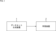
- FIG. 1 is a diagram illustrating a configuration example of an AI learning system according to an embodiment of the present technology.
- the AI learning system is composed of a dataset generation device 1 and a learning device 2.
- the dataset generation device 1 is an information processing device that displays a GUI (Graphical User Interface) for inputting AI use cases, etc., and generates a dataset composed of multiple learning images according to the use case.
- a training image is an image used for AI learning.
- the dataset is generated, for example, by selecting an image suitable for a use case as a learning image from a group of images held in advance by the dataset generation device 1.
- images generated using CG and images taken in real life, and metadata corresponding to each image are registered in a database.
- the metadata corresponding to each image includes information indicating the type of subject and background in the image, a depth map corresponding to the image, a segmentation result for the image, and the like.
- Images registered in the database may be composed of still images or moving images.
- the dataset generation device 1 supplies the generated dataset to the learning device 2.
- the learning device 2 performs learning using the dataset supplied from the dataset generating device 1, and generates an AI engine including an AI (learning model).
- the learning device 2 may perform AI relearning using the dataset supplied from the dataset generating device 1.
- the learning device 2 may be configured to include the dataset generating device 1. In this case, when the user inputs a use case using the GUI, the learning device 2 can generate a data set and perform AI learning.
- step S1 the user uses the GUI displayed by the dataset generation device 1 to input various settings for generating the dataset.
- the dataset generation device 1 receives input of common settings, use cases, and user settings via the GUI.
- step S5 the dataset generation device 1 generates a dataset.
- images according to the common settings, use cases, and user settings input via the GUI are selected as training images from among the images registered in the database, and the image dataset and metadata are A set is generated.
- the image data set is a data set made up of a plurality of learning images
- the metadata set is a data set made up of metadata corresponding to each of the plurality of learning images. Details of data set generation will be described later with reference to FIG. 4.
- step S6 the dataset generation device 1 displays a preview of the learning image on the GUI.
- step S7 the user views the preview display of the learning images on the GUI and determines whether the image dataset generated by the dataset generation device 1 is a desired dataset.
- step S7 If it is determined in step S7 that the image data set is not the desired data set, the process returns to step S1, and the user further inputs or changes settings using the GUI. For example, the user can input additional images, which are images that the user wants to add to the image dataset, or input a 3DCG scene.
- step S8 the dataset generation device 1 receives input of additional images via the GUI.
- additional images For example, an option indicating whether to replace the additional image with an image from the database is input together with the additional image.
- step S9 the dataset generation device 1 determines whether to replace the additional image with an image from the database based on the option.
- the dataset generation device 1 replaces the image group held in the database based on the additional image with the following: Select images to add to the image dataset. Specifically, the dataset generation device 1 searches for an image similar to the additional image (similar image) from among the image group held in the database and adds it to the image dataset.
- step S8 if it is determined in step S8 that the additional image is not replaced with an image from the database, the dataset generation device 1 adds the additional image as is to the image dataset, and displays a preview of the learning image in step S6.
- the dataset generation device 1 receives input of a 3DCG scene via the GUI.
- a 3DCG scene file including a CG (Computer Graphics) 3D model (CG model) and rendering settings are input to the dataset generation device 1.
- CG model refers to a model of a three-dimensional object and surrounding environment formed in a virtual space.
- step S11 the dataset generation device 1 generates a rendered image by performing rendering using the 3DCG scene file, and adds the rendered image to the image dataset. After that, in step S6, the dataset generation device 1 displays a preview of the learning image.
- the user can input common settings, use cases, user settings, additional images, and 3DCG scenes in any order.
- the user looks at the training image preview display that is updated each time each setting is entered as described above, and if the user determines that the image dataset is the desired dataset, clicks the camera simulation execution button on the GUI. Press down. The flow after pressing the camera simulation execution button will be described later with reference to FIG.
- FIG. 3 is a diagram showing an example of an input interface for each setting and an example of information input for each setting.
- Common settings are input using an input interface such as a text box, pull-down menu, or icon.
- Common settings input includes information about the camera for camera simulation (camera information), the number of learning images to be output, the resolution of the output learning images, the format of the output images, and whether live-action images or CG images are to be used as learning images.
- the user inputs information such as which image is desired and whether to perform augmentation.
- Use case input is performed using input interfaces such as text boxes, pull-down menus, and icons.
- input interfaces such as text boxes, pull-down menus, and icons.
- the type of use case such as person recognition or noise reduction, is input.
- User settings are entered using input interfaces such as text boxes, pull-down menus, icons, and slider bars.
- conditions desired by the user for the learning images are input, such as metadata such as the type of subject and background, and image statistics such as brightness and frequency.
- Inputting additional images is performed using input interfaces such as drag and drop, text boxes, pull-down menus, and icons.
- input interfaces such as drag and drop, text boxes, pull-down menus, and icons.
- 3DCG scenes are input using input interfaces such as drag and drop, text boxes, pull-down menus, and icons.
- input interfaces such as drag and drop, text boxes, pull-down menus, and icons.
- the 3DCG scene file, renderer settings, and whether to perform augmentation by moving the virtual camera or moving the subject are input.
- one of three processes from steps S31 to S33 is performed depending on the type of settings input via the GUI. It is assumed that common settings are commonly input in each of the three processes of steps S31 to S33.
- the dataset generation device 1 When the use case and common settings are input, in step S31, the dataset generation device 1 generates an image suitable for the use case from among the image group registered in the database, for example, based on the input common settings. Select as many images as learning images. For example, the dataset generation device 1 selects an image suitable for a use case based on a table in which each image registered in a database, a score for the use case, metadata, statistics, etc. are registered. The score for a use case indicates the degree to which each image registered in the database is suitable as a training image for AI used in a certain use case.
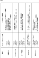
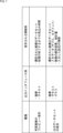
- FIG. 5 is a diagram showing an example of a table used to select an image suitable for a use case.
- the ID of each image registered in the database, image file, score for the use case, subject, and background (scene) are registered in the table.
- use cases include NR (Noise Reduction), person recognition, object recognition, and depth estimation.
- NR Noise Reduction
- person recognition person recognition
- object recognition object recognition
- depth estimation depth estimation
- the image assigned ID 001 is given a score of 8 for NR, a score of 7 for person recognition, a score of 4 for object recognition, and a score of 6 for depth estimation.
- the image assigned ID 001 shows a dog and a person as the subject, and that the room is shown as the background.
- the image assigned ID 002 is given a score of 5 for NR, a score of 6 for person recognition, a score of 5 for object recognition, and a score of 7 for depth estimation.
- the image assigned ID 002 includes people, cars, and bicycles as subjects, and that the image shows the city as the background.
- the image assigned ID 003 is given a score of 4 for NR, a score of 6 for person recognition, a score of 1 for object recognition, and a score of 3 for depth estimation.
- the image assigned ID 003 includes a person as the subject, and that the image includes a river as the background.
- the image assigned ID 004 is given a score of 3 for NR, a score of 2 for person recognition, a score of 4 for object recognition, and a score of 5 for depth estimation.
- the image assigned the ID 004 shows a car and a signboard as the subject, and that it shows the forest as the background.
- the dataset generation device 1 selects, as learning images, the number of images input in the common setting, from among the images registered in the database, in descending order of the scores for the use case input via the GUI. .
- the dataset generation device 1 selects a learning image by, for example, referring to metadata registered in the database. Specifically, the dataset generation device 1 inputs images corresponding to the user's wishes input in the user settings based on the above-mentioned table from among the image group registered in the database, using common settings. The selected number of images are selected as learning images.
- the dataset generation device 1 searches for an image similar to the additional image from among the image groups registered in the database, and adds it to the image dataset. to add. For example, if the number of training images included in the dataset exceeds the number entered in the common settings due to the addition of images similar to the additional images, the number of training images will be changed to the number entered in the common settings. Some of the images originally included in the dataset are removed from the dataset so that the number of images is equal to the number of images originally included in the dataset. For example, images to be excluded from the dataset may be determined based on the score of each learning image for the use case, such as excluding images from the dataset in descending order of the score for the use case.
- step S41 the dataset generation device 1 receives a press of the camera simulation execution button via the GUI.
- the dataset generation device 1 When the camera simulation execution button is pressed, the dataset generation device 1 performs steps S42 and S46, which are shown surrounded by broken lines.
- step S42 the dataset generation device 1 executes camera simulation.
- images included in an image dataset, additional images, and rendered images are processed based on camera information for camera simulation to generate a simulated image dataset.
- the data set generation device 1 generates, for example, an image that reproduces an image taken by the camera indicated by the camera information, through processing processing based on the camera information.
- the images included in the simulated image data set are images included in the image data set, additional images, and rendered images, including noise generated on the image due to shooting with the camera to be reproduced.
- the camera to be reproduced in the camera simulation is, for example, a camera that captures an image that is input to the AI generated by the learning device 2.
- the images, additional images, and rendered images included in the image data set to be processed are ideal images.
- the ideal image is an image that does not contain noise or the like.
- step S43 the dataset generation device 1 stores the simulated image dataset.
- step S44 the dataset generation device 1 performs image analysis on the simulated image dataset and obtains statistics for the entire simulated image dataset.
- step S45 the dataset generation device 1 stores the statistics of the simulated image dataset.
- step S46 the dataset generation device 1 performs metadata processing on the additional image and the rendered image. Specifically, the dataset generation device 1 performs object recognition on the additional image and the rendered image, and acquires metadata corresponding to each of the additional image and the rendered image.
- step S47 the dataset generation device 1 stores the metadata set generated in the dataset generation in step S5 and the metadata acquired in step S46 as one metadata set.
- step S48 the dataset generation device 1 displays the output dataset on the GUI.
- the output dataset includes a simulated image dataset, statistics for the simulated image dataset, and a metadata set.
- step S49 the user looks at the display of the output data set on the GUI and determines whether the output data set is the desired data set.
- step S49 If it is determined in step S49 that the output data set is not the desired data set, the process returns to step S1 in FIG. 2, and the user further inputs or changes settings using the GUI.
- step S49 if it is determined in step S49 that the output data set is the desired data set, the user operates the learning device 2 to perform AI learning in step S50.
- the output dataset output from the dataset generation device 1 via the GUI is used for AI learning.
- FIG. 7 is a diagram showing an example of an output interface displayed on the GUI and an example of displayed information.
- the preview display of the learning image is performed using an output interface such as an image or text.
- the dataset including the image selected as the learning image, the estimated time until the camera simulation process is completed, etc. are displayed.
- the display of the output data set is performed using an output interface such as images, text, and graphs.
- the output dataset display includes the dataset containing the images selected as training images (simulated images), the metadata corresponding to each training image, the analysis results of each training image, the statistics of the entire image dataset, and the input Information about the settings that have been made will be displayed.
- the GUI displayed by the data set generation device 1 will be described with reference to FIGS. 8 to 17.
- the dataset generation device 1 an input GUI for the user to input use cases and the like, and an output GUI for the user to check the output dataset are displayed.
- the input GUI is displayed before the camera simulation is performed, and the output GUI is displayed after the camera simulation is performed and before the output data set is output to the learning device 2.
- FIG. 8 is a diagram showing a first display example of the input GUI.
- the input GUI is composed of an input area A1 and a preview area A2.
- a screen including input means for inputting various settings is displayed, and in the preview area A2, a preview of the learning image is displayed.
- a screen for inputting any of common settings, use cases, user settings, additional images, and 3DCG scenes is displayed in input area A1.
- the tab T1 is shown in white, indicating that the tab T1 among the tabs T1 to T5 is selected.
- a common setting input screen which is a screen including input means for inputting common settings, is displayed in the input area A1.
- An input box B1 for inputting the number of learning images to be output is displayed at the upper left of the common setting input screen. In the example of FIG. 8, it is input that 1000 learning images are to be output.
- an input box B2 is displayed for inputting information regarding the image sensor provided in the camera to be reproduced in the camera simulation.
- information regarding the image sensor for example, the model number of the image sensor and the characteristics of the image sensor are input.
- the data set generation device 1 can simulate noise that occurs when an image is acquired by the image sensor. In the example of FIG. 8, the model number "IMX290" is input.
- an input box B3 is displayed for inputting information regarding the lens provided in the camera to be reproduced in the camera simulation.
- the type of lens is input as the information regarding the lens.
- the type of "wide-angle lens" is input.
- a check box C1 for selecting whether to input detailed settings is displayed below the input box B3. If you select to perform detailed settings, for example, an input method for inputting PSF (Point Spread Function) and distortion data measured for the camera to be reproduced will be displayed on the common settings input screen. .
- PSF Point Spread Function
- the above-mentioned information regarding the image sensor, information regarding the lens, and detailed settings are included in the camera information for camera simulation.
- Information regarding camera settings and photographing conditions may be input as the camera information.
- An input box B4 for inputting augmentation settings is displayed below the check box C1.
- the augmentation settings what is to be changed by the augmentation, such as changing the amount of noise or brightness, is input.
- the input is to create a dark image and a bright image by changing the brightness of the image. If there is no need to perform augmentation, the user may, for example, not input settings for augmentation or input a setting not to perform augmentation.
- An input box B5 for inputting the format (data format) of the learning image to be output is displayed below the input box B4.
- the format of ".exr" is input.
- An input box B6 for inputting the resolution of the learning image to be output is displayed below the input box B5.
- the input is to output a learning image with a width of 4000 pixels and a height of 3000 pixels.
- FIG. 9 is a diagram showing a second display example of the input GUI.
- tab T2 is shown in white, indicating that tab T2 is selected from tabs T1 to T5.
- a use case input screen which is a screen including input means for inputting a use case, is displayed in the input area A1.
- An input box B11 for inputting a use case is displayed at the upper left of the use case input screen.
- the AI use case is noise reduction.
- a list of possible use cases is displayed below the input box B11 using icons and buttons.
- an icon I1 and button B12 indicating noise reduction an icon I2 and button B13 indicating person recognition, and an icon I3 and button B14 indicating object recognition are displayed. Since noise reduction has been input as a use case in the input box B11, the icon I1 and button B12 indicating noise reduction are highlighted compared to other icons and buttons, as shown surrounded by thick lines in FIG. be done.
- the user can input the purpose of using AI (use case) by inputting using the input box B11 or by pressing an icon or box.
- AI use case
- the input use case is reflected in the display of icons and buttons
- the input use case is reflected in the display of icons and buttons. It is also reflected in the display of input box B11.
- a preview display is performed in the preview area A2 that displays a list of learning images selected based on the common settings and use cases.
- thumbnail images representing each learning image are displayed side by side.
- 4 ⁇ 3 (vertical ⁇ horizontal) thumbnail images are displayed in a tiled arrangement.
- the dataset generation device 1 switches the thumbnail images displayed in the preview area A2 by accepting a predetermined operation by the user.
- information regarding the number of selected learning images is displayed as white and black circles shown below the thumbnail image.
- An input box B21 for presenting the estimated time until the camera simulation process is completed is displayed at the lower left of the preview area A2. In the example of FIG. 9, it is displayed that the estimated time until the camera simulation process is completed is one hour.
- a camera simulation execution button B22 is displayed at the bottom right of the preview area A2.
- a preview of the simulated image may be displayed in the preview area A2.
- one predetermined image that has been processed based on the input camera information is displayed on the right side of the thumbnail image of the learning image.
- the predetermined one image may be one of the learning images included in the image data set, or may be one predetermined image.
- the user can check whether the processing performed on the image in the camera simulation is the desired processing by viewing the preview display of the simulated image.
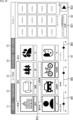
- FIG. 10 is a diagram showing a third display example of the input GUI.
- tab T3 is shown in white, indicating that tab T3 is selected from tabs T1 to T5.
- a user setting input screen which is a screen including input means for inputting user settings, is displayed in the input area A1.
- An input box B31 for inputting the type of background of the learning image is displayed at the top of the user setting input screen. In the example of FIG. 10, it is input that a learning image showing the city as a background is to be output.
- a list of possible backgrounds is displayed below the input box B31 using icons and buttons.
- icons and buttons representing each of the city, room, forest, and river are displayed. Since the city has been entered as the background in the input box B31, the icons and buttons representing the city are displayed with emphasis compared to other icons and buttons, as shown surrounded by thick lines in FIG.
- the user can input the type of background desired as the background of the learning image by inputting using the input box B31 or by pressing an icon or button.
- the input background type is also reflected in the display of icons and buttons, and when the type of background is input using the icon or button, the input The type of background is also reflected in the display of input box B31.
- An input box B32 for inputting the type of subject of the learning image is displayed below the button indicating the type of background. In the example of FIG. 10, it is input that a learning image showing a person and a bicycle as subjects is to be output.
- a list of possible subjects is displayed below the input box B32 using icons and buttons.
- icons and buttons representing each of a person, a car, a bicycle, and a dog are displayed. Since a person and a bicycle are input as subjects in the input box B32, the icons and buttons representing the person and bicycle are emphasized compared to other icons and buttons, as shown surrounded by thick lines in FIG. Is displayed.
- the user can input the type of subject desired as the subject of the learning image by inputting using the input box B32 or by pressing an icon or button.
- the input type of subject is also reflected in the display of icons and buttons, and when the type of subject is input using the icon or button, the input The type of subject is also reflected in the display of input box B32.
- a slider bar SB1 is displayed for inputting the brightness of the image.
- the user can adjust the brightness of the learning image by moving the slider on the slider bar SB1.
- the dataset generation device 1 for example, selects as the learning image an image darker than the image originally selected as the learning image. .
- the data set generation device 1 can also change the brightness of the learning image without changing the learning image according to the user's operation.
- a slider bar SB2 for inputting the image frequency is displayed at the bottom center of the user setting input screen.
- the user can adjust the frequency of the learning image by moving the slider on the slider bar SB2.
- the dataset generation device 1 when the slider on the slider bar SB2 is moved to the left by the user, the dataset generation device 1 generates an image in which the pattern of the subject is flatter than the image originally selected as the learning image. (e.g., an image whose color does not change much) as a training image.
- the data set generation device 1 can also change the frequency of the learning image without changing the learning image according to the user's operation.
- a slider bar SB3 for inputting the image contrast is displayed.
- the user can adjust the contrast of the learning image by moving the slider on the slider bar SB3.
- the dataset generation device 1 for example, selects an image with lower contrast as the learning image than the image originally selected as the learning image. select.
- the data set generation device 1 can also change the contrast of the learning image without changing the learning image in response to a user's operation.
- FIG. 11 is a diagram showing a fourth display example of the input GUI.
- the tab T4 is shown in white, indicating that the tab T4 is selected from among the tabs T1 to T5.
- an additional image input screen that is a screen including input means for inputting additional images is displayed in the input area A1.
- An input box B41 for inputting an additional image is displayed at the upper left of the additional image input screen.
- the path of the additional image is input into the input box B41.
- the path "C: ⁇ Users ⁇ Pictures ⁇ dog.png" is input.
- the additional images may be composed of still images or moving images.
- a check box C11 is displayed below the input box B41 for selecting whether or not to search for an image similar to the additional image from the database.
- the dataset generation device 1 searches for a similar image to be added from among the image group registered in the database, and adds the similar image to the image dataset.
- a list of learning images including the additional image or images similar to the additional image is displayed in the preview area A2.
- FIG. 12 is a diagram showing a fifth display example of the input GUI.
- tab T5 is shown in white, indicating that tab T5 is selected from tabs T1 to T5.
- a 3DCG scene input screen which is a screen including input means for inputting a 3DCG scene, is displayed in the input area A1.
- An input box B51 for inputting a 3DCG scene file is displayed at the upper left of the 3DCG scene input screen. For example, a path of a 3DCG scene file is input into the input box B51. In the example of FIG. 12, the path "C: ⁇ Users ⁇ Documents ⁇ animal.max" is input.
- an input box B52 is displayed for inputting the renderer used for rendering the 3DCG scene.
- the renderer "S-Render" is input.
- an input box B53 is displayed for inputting a virtual camera that will be the viewpoint of the rendered image among the virtual cameras arranged in the virtual space.
- a virtual camera that will be the viewpoint of the rendered image among the virtual cameras arranged in the virtual space.
- An input box B54 for inputting augmentation settings is displayed below the input box B53.
- the augmentation settings what is to be changed by the augmentation, such as rotating the virtual camera, is input. In the example of FIG. 12, it is input that a plurality of images are created by rotating a (virtual) camera during rendering. If there is no need to perform augmentation, the user may, for example, not input settings for augmentation or input a setting not to perform augmentation.
- a list of learning images including rendered images generated based on the 3DCG scene file is displayed in the preview area A2.
- the rendered image may be composed of a still image or a moving image.
- the output GUI is displayed, for example, when the camera simulation execution button B22 is pressed on the input GUI and the camera simulation processing is completed.
- FIG. 13 is a diagram showing a first display example of the output GUI.
- the output GUI is composed of an output data set display area A11.
- the output data set is displayed.
- tabs T11 to T14 are displayed above the output data set display area A11.
- you can check the list of simulated learning images, details of the simulated learning images, statistics (analysis results) of the simulated image dataset, and output settings. is displayed in the output data set display area A11.
- the tab T11 is shown in white, indicating that the tab T11 among the tabs T11 to T14 is selected.
- a list of simulated learning images is displayed in the output dataset display area A11.
- a list of simulated learning images is displayed at the top of the output dataset display area A11. Specifically, thumbnail images representing simulated learning images are displayed side by side. In the example of FIG. 13, a combination of three thumbnail images arranged in the depth direction is displayed arranged in the horizontal direction. For example, a plurality of images that are similar to each other, such as images with the same type of subject or images with similar metadata and statistics (brightness, frequency, etc.), are displayed side by side in the depth direction.
- An input box B61 for inputting the type of metadata or the type of statistics (analysis data) of the learning image that the user wants to confirm is displayed below the thumbnail image showing the learning image. In the example of FIG. 13, it is input that the user wants to check the depth map.
- buttons each indicating a depth map and a segmentation result as metadata, and a frequency, color distribution, and brightness distribution as statistics are displayed. Since the depth map has been input in the input box B61, the icon and button indicating the depth map are highlighted compared to other icons and buttons, as shown surrounded by thick lines in FIG. 13.
- the user can input the type of metadata or the type of statistics that he/she wants to confirm by inputting using the input box B61 or by pressing an icon or button.
- the type of metadata or statistics is also reflected in the display of icons and buttons.
- the type of metadata or statistics is also reflected in the display of the input box B61.
- buttons indicating the types of metadata and statistics a list of the types of metadata and statistics entered using the input box B61 etc. is displayed. Specifically, images showing the types of metadata and statistics input using the input box B61 or the like are displayed side by side. The positions of the images showing metadata and statistics correspond to the positions of simulated learning images displayed at the top of the output data set display area A11. For example, an image indicating metadata corresponding to a learning image displayed on the first front side from the left in the upper part of the output dataset display area A11 is displayed on the first front side from the left in the lower part of the output dataset display area A11. will be displayed.
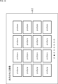
- a learning image list screen A12 shown in FIG. 14 is displayed as a pop-up, for example.
- a list of simulated learning images is displayed on the learning image list screen A12.
- thumbnail images representing simulated learning images are displayed in a tiled manner.
- 4 ⁇ 4 (vertical ⁇ horizontal) thumbnail images are displayed side by side.
- the dataset generation device 1 switches the thumbnail images displayed on the learning image list screen A12 by accepting a predetermined operation by the user.
- the learning image list screen A12 in FIG. 14 information regarding the number of simulated learning images is displayed as white and black circles shown below the thumbnail image.
- FIG. 15 is a diagram showing a second display example of the output GUI.
- the tab T12 is shown in white, indicating that the tab T12 is selected from among the tabs T11 to T14. In this case, details of the simulated learning image are displayed in the output data set display area A11.
- an input box B71 is displayed for inputting the type of metadata or the type of statistics that the user wants to confirm.
- it is input that the user wants to check the depth map, segmentation, frequency, color distribution, and brightness distribution.
- buttons On the right side of the input box B71, a list of displayable metadata and statistics is displayed using icons and buttons.
- icons and buttons each indicating a depth map, segmentation, frequency, color distribution, and brightness distribution are displayed. Since the depth map, segmentation, frequency, color distribution, and brightness distribution are input in the input box B71, the icons and buttons indicating the depth map, segmentation, frequency, color distribution, and brightness distribution are shown as thick lines in FIG. It is highlighted and displayed as shown in the box.
- the user can input the type of metadata or the type of statistics that he/she wishes to confirm by inputting using the input box B71 or by pressing an icon or button.
- the type of metadata or statistics is also reflected in the display of icons and buttons.
- the type of metadata or statistics is also reflected in the display of the input box B71.
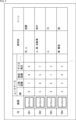
- a table is displayed in which images indicating the type of metadata input using the input box B71 or the like and graphs indicating statistics are registered in association with learning images.
- the ID of the learning image the thumbnail image of the learning image, the depth map, the image showing the segmentation result, the graph showing the frequency, the graph showing the color distribution, and the brightness histogram are displayed in a list.
- the ID of the learning image is not the ID assigned to each image in the database, but the ID newly assigned to the image selected as the learning image.
- FIG. 16 is a diagram showing a third display example of the output GUI.
- tab T13 is shown in white, indicating that tab T13 is selected from tabs T11 to T14.
- the statistics (analytical data) of the entire simulated image data set are displayed in the output data set display area A11.
- an input box B81 is displayed for inputting the type of statistics for the entire image dataset that the user wants to confirm.
- it is input that the user wants to check the color distribution and brightness distribution.
- buttons On the lower left side of the input box B81, a list of displayable statistics is displayed using icons and buttons.
- icons and buttons each indicating frequency, color distribution, and brightness distribution are displayed. Since the color distribution and brightness distribution have been input in the input box B81, the icons and buttons indicating the color distribution and brightness distribution are emphasized more than other icons and buttons, as shown surrounded by thick lines in FIG. will be displayed.
- the user can input the type of statistics he or she wants to check by using the input box B81 or by pressing an icon or button.
- the input type of statistics is reflected in the display of icons and buttons, and when the type of statistics is input using the icons and buttons, The type of statistics input is also reflected in the display of input box B81.
- a graph showing the statistical amount of the type input using the input box B81 or the like is displayed.
- a graph showing the color distribution of a plurality of learning images included in the simulated image data set and a graph showing the brightness distribution of the plurality of learning images are displayed.
- a table indicating the types of subjects and backgrounds (scenes) of each learning image is displayed.
- the type of subject of each learning image is shown in three granularity: large items, medium items, and small items.
- the subject of the learning image assigned ID 001 is an animal in the large category, a dog in the medium category, and a papillon in the small category.
- the subject of the learning image assigned ID 002 is a vehicle in the major category, and a car in the medium category.
- a box B82 is displayed to visually indicate the distribution of types of subjects and backgrounds in the image dataset.
- the size of the text indicating the subject is changed and displayed, depending on the number of learning images in which the same subject is captured, for example.
- the larger the number of learning images in which the same subject appears the larger the size of the character indicating the subject is displayed.
- the user can also press any one of the large item, medium item, and small item in the table at the bottom left of the output data set display area A11.
- the data set generation device 1 displays in box B82 according to the number of learning images that include animals, vehicles, etc., and when the middle item part of the table is pressed. , a box B82 is displayed in accordance with the number of learning images in which dogs, cars, etc. appear. In this way, the user can specify the granularity of the type of subject displayed in box B82 by pressing any one of the large item, medium item, and small item in the table.
- the user can confirm whether the output data set is the desired data set.
- the user inputs output settings using the output GUI described with reference to FIG.
- FIG. 17 is a diagram showing a fourth display example of the output GUI.
- the tab T14 is shown in white, indicating that the tab T14 is selected from among the tabs T11 to T14.
- input means for inputting output settings is displayed in the output data set display area A11.
- an input box B91 is displayed for inputting the type of statistics (analysis data) that the user wants to include in the output dataset.
- the input is to output an output data set including data indicating color distribution and brightness distribution.
- buttons On the lower left side of the input box B91, a list of statistics that can be output is displayed using icons and buttons.
- icons and buttons each indicating frequency, color distribution, and brightness distribution are displayed. Since the color distribution and brightness distribution have been input in the input box B91, the icons and buttons indicating the color distribution and brightness distribution are emphasized more than other icons and buttons, as shown surrounded by thick lines in FIG. will be displayed.
- the user can input the type of statistics to be output by inputting using the input box B91 or by pressing an icon or button.
- the input type of statistics is also reflected in the display of icons and buttons, and when the type of statistics is input using the icons and buttons, The type of statistics input is also reflected in the display of input box B91.
- the statistics to be output may be the statistics of each learning image, or the statistics of the entire image data set.
- an input box B92 is displayed for the user to input the type of metadata that he or she wants to include in the output data set.
- the depth map is to be output as a metadata set.
- a list of metadata that can be output is displayed using icons and buttons.
- icons and buttons each indicating a depth map and a segmentation result are displayed. Since the depth map has been input in the input box B92, the icon and button indicating the depth map are displayed more emphasized than other icons and buttons, as shown surrounded by thick lines in FIG. 17.
- the user can input the type of metadata to be output by inputting using the input box B92 or by pressing an icon or button.
- the input type of metadata is also reflected in the display of icons and buttons, and when the type of metadata is input using the icon or button, The type of metadata input is also reflected in the display of input box B92.
- An input box B93 for inputting the path of the folder to which the output data set is output is displayed below the button indicating the type of metadata.
- the path "C: ⁇ Users ⁇ Documents" is input.
- the dataset generation device 1 After output settings are input using the output GUI described with reference to FIG. 17, for example, when a predetermined operation is accepted, the dataset generation device 1 outputs an output dataset.
- the input box is a pull-down menu that allows you to select a desired menu, a text box that allows you to enter text, or a box that allows you to select a desired menu or enter text. This is achieved using a combo box, etc. that can do this.
- the user only needs to input an AI use case using the input GUI and output GUI displayed by the dataset generation device 1, and the user can select a Learning images can be obtained. Users will be able to easily obtain training images suitable for AI learning with simple operations, without having to actually take pictures or search for images publicly available on the Internet.
- the dataset generation device 1 when only images that can be used without a license are registered in the database, the user can acquire a large amount of learning images without worrying about the license.
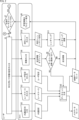
- FIG. 18 is a block diagram showing an example of the configuration of the dataset generation device 1.
- the dataset generation device 1 includes an input/output I/F 11, an input information acquisition section 12, a dataset generation section 13, a dataset database 14, a rendering section 15, a camera simulation execution section 16, and an image analysis section. 17, a metadata processing section 18, an output data set storage section 19, a display control section 20, and a display section 21.
- the input/output I/F 11 is an interface for inputting data to the dataset generation device 1 and outputting data from the dataset generation device 1.
- the data set generation device 1 may include separate input I/F and output I/F.
- the input/output I/F 11 detects the user's operation on the input GUI or the output GUI, and supplies information indicating the operation contents to the input information acquisition unit 12. Further, the input/output I/F 11 acquires the output data set from the output data set storage unit 19 via a path not shown, and outputs it to the learning device 2.
- the input information acquisition unit 12 acquires information on various settings input by the user based on the information supplied from the input/output I/F 11.
- the input information acquisition unit 12 supplies information regarding common settings, use cases, user settings, and additional images to the dataset generation unit 13.
- the input information acquisition unit 12 supplies information regarding the 3DCG scene to the rendering unit 15. When not searching for an image similar to the additional image, the input information acquisition unit 12 supplies the additional image to the camera simulation execution unit 16 and the metadata processing unit 18.
- the dataset generation unit 13 selects learning images from the image group registered in the dataset database 14 based on the information supplied from the input information acquisition unit 12, and generates an image dataset.
- the dataset generation unit 13 functions as a selection unit that selects learning images from a group of images registered in the dataset database 14. Further, the dataset generation unit 13 acquires metadata corresponding to the selected learning image from the dataset database 14 and generates a metadata set.
- the dataset generation unit 13 searches for an image similar to the additional image from among the image group registered in the dataset database 14, and adds it to the image dataset.
- the dataset generation unit 13 supplies the generated image dataset to the camera simulation execution unit 16 and supplies the metadata set to the output dataset storage unit 19.
- the dataset database 14 is registered in advance with images generated using CG, images shot with live action, and metadata and statistics corresponding to each image.
- the rendering unit 15 performs rendering based on the information regarding the 3DCG scene supplied from the input information acquisition unit 12, and generates a rendered image.
- the rendering unit 15 supplies the rendered image to the camera simulation execution unit 16 and the metadata processing unit 18.
- the camera simulation execution unit 16 uses the additional images supplied from the input information acquisition unit 12, each learning image included in the image dataset supplied from the dataset generation unit 13, and the rendered image supplied from the rendering unit 15. Perform camera simulation on the image to generate a simulated image dataset.
- the camera simulation execution unit 16 functions as a processing unit that performs processing based on camera information on additional images, learning images included in the image dataset, and rendered images.
- FIG. 19 is a diagram showing an example of camera simulation.
- the camera simulation execution unit 16 generates a degraded image by adding to the ideal image the degradation and noise that occur on the image due to photography by the camera to be reproduced.
- the camera simulation execution unit 16 performs deterioration by applying a model that convolves the deterioration factor K with the ideal image I and adds noise n, as shown in the following equation (1), for example. Generate image I'.
- AI estimates the degradation factors and noise contained in degraded images.
- arrow #1 in Figure 20 when an AI engine that includes AI receives a photographed image containing the same degradation and noise as the degradation and noise contained in the degraded image used during learning, the AI engine outputs a high-quality reconstructed image that is close to the ideal image, as shown by arrow #2.
- the camera simulation execution unit 16 generates a degraded image that includes the degradation and noise that occurs on the image due to photography by the camera that is the target of reproduction, and the AI that receives the captured image that is captured by the camera that is the target of reproduction as input.
- An image dataset including degraded images suitable for learning can be generated.
- the camera simulation execution unit 16 may generate the degraded image by applying a model corresponding to the lens system of the camera to be reproduced and a model corresponding to the sensor system to the ideal image. .
- the model corresponding to the lens system may be a model that adds deterioration such as blur, distortion, shading, flare, ghost, etc. caused by aberration, transmittance, optical filter, stray light, etc. in the lens to the ideal image.
- the model corresponding to the sensor system may be a model that adds deterioration caused by spectroscopy, color mixing, photoelectric conversion, etc. in the sensor to the ideal image.
- the model corresponding to the sensor system may be a model that adds optical shot noise, dark current shot noise, random shot noise, pattern noise, white spot noise, addition of pixel values, etc. in the sensor to the ideal image. .
- the camera simulation execution unit 16 may generate a degraded image by applying a compression algorithm, converting a compression rate, compressing at a variable bit rate, thinning out gradations, etc.
- the camera simulation execution unit 16 may generate a degraded image by thinning out frames.
- the camera simulation execution unit 16 may generate a degraded image by applying a model that adds degradation that takes into account defects in images captured by the sensor to an ideal image.
- pixel defects include pixels for image plane phase difference acquisition, polarization pixels, IR acquisition pixels, UV acquisition pixels, ranging pixels, temperature pixels, etc.
- the defect may be due to at least one of the pixels that are not used in the image.
- the camera simulation execution unit 16 may generate a degraded image by applying a model that takes other characteristics of the sensor into consideration.
- the model is a model that can obtain degraded images that takes into account sensor color filter characteristics, color filter array, temperature characteristics, conversion efficiency, sensitivity (HDR synthesis, gain characteristics), readout order (rolling shutter distortion), etc. Good too.
- the camera simulation execution unit 16 may generate a degraded image by applying a model that can acquire an image considering a camera compatible with multispectral images and hyperspectral images.
- the camera simulation execution unit 16 may generate a degraded image by performing conversion to reproduce the shooting conditions.
- the photographing conditions are, for example, conditions such as illumination, saturation, and exposure.
- Illumination indicates, for example, the type of light source.
- conversion may be performed to reproduce light sources such as sunlight, tunnel lighting, and street lights.
- conversion may be performed to reproduce not only the type of light source but also the position of the light source and the direction in which the light source is facing.
- Deterioration due to saturation is, for example, blown-out highlights, and indicates deterioration that exceeds the maximum color value of a pixel value due to reflections from surrounding pixels.
- Deterioration due to exposure is deterioration caused by conditions such as shutter speed and aperture, and indicates underexposure, overexposure, etc.
- a transformation may be performed to reproduce the focus of the lens.
- the camera simulation execution unit 16 supplies the simulated image data set to the image analysis unit 17 and the output data set storage unit 19.
- the image analysis unit 17 performs image analysis of the learning images included in the simulated image data set supplied from the camera simulation execution unit 16, and obtains statistics of the entire image data set.
- the image analysis unit 17 supplies statistics of the entire image data set to the output data set storage unit 19.
- the metadata processing unit 18 performs metadata processing on the additional image supplied from the input information acquisition unit 12 and the rendered image supplied from the rendering unit 15, and generates metadata corresponding to each of the additional image and the rendered image. get.
- the metadata processing unit 18 supplies metadata corresponding to each of the additional image and the rendered image to the output data set storage unit 19.
- the output dataset storage section 19 stores the metadata set supplied from the dataset generation section 13 , the simulated image dataset supplied from the camera simulation execution section 16 , and the simulated image supplied from the image analysis section 17 . Store the statistics of the dataset as an output dataset.
- the output data set storage unit 19 stores metadata corresponding to each of the additional image and the rendered image supplied from the metadata processing unit 18 in addition to the metadata set.
- the display control unit 20 acquires information from each component of the data set generation device 1 through a path not shown, generates an input GUI and an output GUI, and displays the generated GUI on the display unit 21.
- the display unit 21 is configured by, for example, a display, and displays an input GUI and an output GUI under the control of the display control unit 20. Note that the display section 21 may be provided in an external device.
- step S101 the input information acquisition unit 12 receives input of common settings from the user.
- step S102 the input information acquisition unit 12 receives input of a use case from the user. Note that if the use case of the AI generated by learning using the output data set is not expected by the user, the process of step S102 is skipped.
- step S103 the input information acquisition unit 12 receives input of user settings from the user. Note that if the user does not want to make detailed settings, the process of step S103 is skipped.
- step S104 the input information acquisition unit 12 accepts input of additional images by the user. Note that if there is no image that the user wants to add to the image data set, the process of step S104 is skipped.
- step S105 the input information acquisition unit 12 accepts input of additional images by the user. Note that if the user does not want to add the rendered image to the image data set, the process of step S105 is skipped.
- step S106 the input information acquisition unit 12 determines whether the camera simulation execution button has been pressed.
- step S106 If it is determined in step S106 that the camera simulation execution button has not been pressed, the process returns to step S101, and the subsequent processes are repeated.
- an image data set is generated according to the input settings, and a preview of the learning image is displayed on the input GUI.
- the user looks at the preview display of the learning images and determines whether the image data set is the desired data set.
- the user presses the camera simulation execution button. If it is determined in step S106 that the camera simulation execution button has been pressed, the process proceeds to step S107.
- step S107 the camera simulation execution unit 16 executes camera simulation and generates a simulated learning data set.
- step S108 the input/output I/F 11 outputs an output data set including the simulated learning data set.
- the user can simply input the AI use case etc. using the input GUI and output GUI displayed by the dataset generation device 1, and the user can select the Learning images can be obtained. Users will be able to easily obtain training images suitable for AI learning with simple operations, without having to actually take pictures or search for images publicly available on the Internet.
- FIG. 22 is a diagram showing another display example of the input GUI.
- the input GUI may be configured by the input area A1 excluding the preview area A2.
- the camera simulation execution button B22 is displayed, for example, at the lower right of the input area A1.
- the series of processes described above can be executed by hardware or software.
- a program constituting the software is installed from a program recording medium into a computer built into dedicated hardware or a general-purpose personal computer.
- FIG. 23 is a block diagram showing an example of the hardware configuration of a computer that executes the above-described series of processes using a program.
- the CPU 501, ROM 502, and RAM 503 are interconnected by a bus 504.
- An input/output interface 505 is further connected to the bus 504.
- an input section 506 consisting of a keyboard, a mouse, etc.
- an output section 507 consisting of a display, speakers, etc.
- a storage section 508 consisting of a hard disk or non-volatile memory
- a communication section 509 consisting of a network interface, etc.
- a drive 510 for driving a removable medium 511.
- the CPU 501 executes the series of processes described above by, for example, loading a program stored in the storage unit 508 into the RAM 503 via the input/output interface 505 and the bus 504 and executing it. will be held.
- a program executed by the CPU 501 is installed in the storage unit 508 by being recorded on a removable medium 511 or provided via a wired or wireless transmission medium such as a local area network, the Internet, or digital broadcasting.
- the program executed by the computer may be a program in which processing is performed chronologically in accordance with the order described in this specification, or may be a program in which processing is performed in parallel or at necessary timing such as when a call is made. It may also be a program that is carried out.
- a system refers to a collection of multiple components (devices, modules (components), etc.), regardless of whether all the components are located in the same casing. Therefore, multiple devices housed in separate casings and connected via a network, and a single device with multiple modules housed in one casing are both systems. .
- the present technology can take a cloud computing configuration in which one function is shared and jointly processed by multiple devices via a network.
- each step described in the above flowchart can be executed by one device or can be shared and executed by multiple devices.
- one step includes multiple processes
- the multiple processes included in that one step can be executed by one device or can be shared and executed by multiple devices.
- An information processing device comprising: a selection unit that selects a learning image to be used for learning the learning model from a group of images held in advance, according to a use case of a learning model that inputs an image.
- the information processing device according to (1) further comprising a display control unit that displays an input means for a user to input the use case.
- the input means for inputting the use case includes any one of a pull-down menu, a text box, a combo box, and an icon.
- the information processing device performs the processing by adding at least one of deterioration and noise that occurs in images taken by the camera to the learning image.
- the display control unit displays a list of images selected as the learning images before the processing is performed on the learning images.
- the display control unit displays the processed image before the processing is performed on the learning image. .
- the display control unit displays input means for inputting information regarding the camera.
- the information processing device includes information regarding at least one of an image sensor and a lens provided in the camera.
- the input means for inputting information regarding the camera includes input means for inputting at least one of the model number or characteristics of the image sensor, and the type of the lens.
- Processing equipment. (11)
- the selection unit selects the learning image from the group of images according to at least one of the type of subject, type of background, brightness, frequency, and contrast input by the user. 1) The information processing device according to any one of (10). (12) (1) to (11) above, wherein the selection unit adds an image selected from the image group based on an image input by the user or an image input by the user as the learning image.
- the information processing device according to any one of. (13) The information processing device according to any one of (1) to (12), wherein the selection unit adds an image generated based on a CG model input by a user as the learning image. (14) The selection unit selects the learning image based on a table in which the degree to which each image included in the image group is suitable for learning the learning model used in a predetermined use case is registered. 1) The information processing device according to any one of (13). (15) an output unit that outputs the learning image to a learning device that performs learning of the learning model; The information processing device according to any one of (1) to (14), further comprising: a display control unit that displays a list of the learning images before the learning images are output.
- the information processing device displays a list of at least one of metadata and statistics corresponding to the learning image before the learning image is output.
- the display control unit Before the learning images are output, the display control unit outputs statistics of a data set constituted by a plurality of learning images, information indicating the type of subject or background of each of the plurality of learning images, and the data set.
- the information processing device according to (15) or (16), wherein the information processing device displays at least one of information indicating a distribution of types of the subject or the background.
- the information processing device An information processing method that selects a learning image to be used for learning a learning model from a group of images held in advance, according to a use case of a learning model that uses images as input.
- a computer that has recorded a program for executing a process that selects learning images to be used for learning the learning model from among a group of pre-held images according to the use case of the learning model that uses images as input.
- a recording medium that can be read.
- 1 Dataset generation device 2 Learning device, 11 Input/output I/F, 12 Input information acquisition unit, 13 Dataset generation device, 14 Dataset database, 15 Rendering unit, 16 Camera simulation execution unit, 17 Image analysis unit, 18 Metadata processing unit, 19 Output data set storage unit, 20 Display control unit, 21 Display unit
Abstract
The present technology relates to an information processing device, an information processing method, and a recording medium that enable easy acquisition of an image suitable for an AI use case. The information processing device according to the present technology comprises a selection unit that selects a training image used for training of a learning model from an image group retained in advance, according to a use case of the learning model accepting an image as an input. The present technique can be applied to, for example, a data set generation device that generates a data set constituted of a large amount of training images.
Description
本技術は、情報処理装置、情報処理方法、および記録媒体に関し、特に、AIのユースケースに適した画像を容易に取得することができるようにした情報処理装置、情報処理方法、および記録媒体に関する。
The present technology relates to an information processing device, an information processing method, and a recording medium, and particularly relates to an information processing device, an information processing method, and a recording medium that can easily acquire images suitable for AI use cases. .
近年、AI(Artificial Intelligence)の学習などの用途を目的として、大量の画像により構成されるデータセットを用意することが必要とされている。例えば、特許文献1には、データソースから収集されたローデータを分類してデータセットを生成するデータ管理システムが記載されている。
In recent years, it has become necessary to prepare datasets consisting of large amounts of images for purposes such as AI (Artificial Intelligence) learning. For example, Patent Document 1 describes a data management system that classifies raw data collected from data sources and generates datasets.
特許文献1に記載のデータ管理システムでは、実際の風景を撮影する、インターネット上で公開されている画像から適切な画像を探す、Webサイト上で公開されているデータセットを利用するといった方法で、ユーザ自身が、AIの学習向けに大量の画像を収集する必要がある。
The data management system described in Patent Document 1 uses methods such as photographing actual scenery, searching for appropriate images from images published on the Internet, and using datasets published on websites. Users themselves need to collect large amounts of images for AI training.
これらの方法では、大量の画像を収集するのに労力がかかったり、収集された画像がAIのユースケースにとって適切でなかったりすることがある。
These methods may require effort to collect large numbers of images, or the images collected may not be appropriate for the AI use case.
本技術はこのような状況に鑑みてなされたものであり、AIのユースケースに適した画像を容易に取得することができるようにするものである。
This technology was developed in light of this situation, and makes it possible to easily obtain images suitable for AI use cases.
本技術の一側面の情報処理装置は、あらかじめ保持している画像群の中から、画像を入力とする学習モデルのユースケースに応じて、前記学習モデルの学習に用いられる学習画像を選択する選択部を備える。
An information processing device according to an aspect of the present technology selects a learning image to be used for learning a learning model from among a group of images held in advance, according to a use case of a learning model that inputs an image. Department.
本技術の一側面の情報処理方法は、情報処理装置が、あらかじめ保持している画像群の中から、画像を入力とする学習モデルのユースケースに応じて、前記学習モデルの学習に用いられる学習画像を選択する。
In an information processing method according to one aspect of the present technology, an information processing device selects a learning model that is used for learning a learning model from among a group of images held in advance according to a use case of a learning model that uses images as input. Select an image.
本技術の一側面の記録媒体は、あらかじめ保持している画像群の中から、画像を入力とする学習モデルのユースケースに応じて、前記学習モデルの学習に用いられる学習画像を選択する処理を実行させるためのプログラムを記録する。
A recording medium according to one aspect of the present technology performs a process of selecting a learning image to be used for learning a learning model from among a group of images stored in advance, according to a use case of a learning model that inputs images. Record the program to be executed.
本技術の一側面においては、あらかじめ保持している画像群の中から、画像を入力とする学習モデルのユースケースに応じて、前記学習モデルの学習に用いられる学習画像が選択される。
In one aspect of the present technology, a learning image to be used for learning the learning model is selected from among a group of images held in advance, according to a use case of a learning model that inputs images.
以下、本技術を実施するための形態について説明する。説明は以下の順序で行う。
1.AI学習システムの概要
2.GUIについて
3.データセット生成装置の構成と動作
4.変形例 Hereinafter, a mode for implementing the present technology will be described. The explanation will be given in the following order.
1. Overview ofAI learning system 2. About GUI 3. Configuration and operation of dataset generation device 4. Variant
1.AI学習システムの概要
2.GUIについて
3.データセット生成装置の構成と動作
4.変形例 Hereinafter, a mode for implementing the present technology will be described. The explanation will be given in the following order.
1. Overview of
<1.AI学習システムの概要>
図1は、本技術の一実施形態に係るAI学習システムの構成例を示す図である。 <1. Overview of AI learning system>
FIG. 1 is a diagram illustrating a configuration example of an AI learning system according to an embodiment of the present technology.
図1は、本技術の一実施形態に係るAI学習システムの構成例を示す図である。 <1. Overview of AI learning system>
FIG. 1 is a diagram illustrating a configuration example of an AI learning system according to an embodiment of the present technology.
図1に示すように、AI学習システムは、データセット生成装置1と学習装置2により構成される。
As shown in FIG. 1, the AI learning system is composed of a dataset generation device 1 and a learning device 2.
データセット生成装置1は、AIのユースケースなどを入力するためのGUI(Graphical User Interface)を表示し、ユースケースに応じた複数の学習画像により構成されるデータセットを生成する情報処理装置である。学習画像は、AIの学習に用いられる画像である。データセットは、例えば、データセット生成装置1があらかじめ保持している画像群の中から、ユースケースに適した画像が学習画像として選択されることで生成される。
The dataset generation device 1 is an information processing device that displays a GUI (Graphical User Interface) for inputting AI use cases, etc., and generates a dataset composed of multiple learning images according to the use case. . A training image is an image used for AI learning. The dataset is generated, for example, by selecting an image suitable for a use case as a learning image from a group of images held in advance by the dataset generation device 1.
データセット生成装置1においては、CGを用いて生成された画像や実写で撮影された画像と、各画像に対応するメタデータとがデータベースに登録されている。各画像に対応するメタデータは、画像に写る被写体の種類や背景の種類を示す情報、画像に対応したデプスマップ、画像に対するセグメンテーション結果などを含む。データベースに登録される画像は、静止画像で構成されてもよいし、動画像で構成されてもよい。
In the data set generation device 1, images generated using CG and images taken in real life, and metadata corresponding to each image are registered in a database. The metadata corresponding to each image includes information indicating the type of subject and background in the image, a depth map corresponding to the image, a segmentation result for the image, and the like. Images registered in the database may be composed of still images or moving images.
データセット生成装置1は、生成したデータセットを学習装置2に供給する。
The dataset generation device 1 supplies the generated dataset to the learning device 2.
学習装置2は、データセット生成装置1から供給されたデータセットを用いた学習を実施し、AI(学習モデル)を含むAIエンジンを生成する。学習装置2は、データセット生成装置1から供給されたデータセットを用いてAIの再学習を行ってもよい。
The learning device 2 performs learning using the dataset supplied from the dataset generating device 1, and generates an AI engine including an AI (learning model). The learning device 2 may perform AI relearning using the dataset supplied from the dataset generating device 1.
なお、学習装置2が、データセット生成装置1を備える構成であってもよい。この場合、ユーザがGUIを用いてユースケースを入力すると、学習装置2がデータセットを生成してAIの学習を行うことも可能である。
Note that the learning device 2 may be configured to include the dataset generating device 1. In this case, when the user inputs a use case using the GUI, the learning device 2 can generate a data set and perform AI learning.
図2を参照して、データセット生成装置1がデータセットを生成する流れを説明する。
With reference to FIG. 2, a flow in which the dataset generation device 1 generates a dataset will be described.
ステップS1において、ユーザは、データセット生成装置1により表示されているGUIを用いて、データセットを生成するための各種の設定を入力する。
In step S1, the user uses the GUI displayed by the dataset generation device 1 to input various settings for generating the dataset.
ステップS2乃至S4において、データセット生成装置1は、共通設定、ユースケース、およびユーザ設定の入力を、GUIを介して受け付ける。
In steps S2 to S4, the dataset generation device 1 receives input of common settings, use cases, and user settings via the GUI.
ステップS5において、データセット生成装置1は、データセット生成を行う。データセット生成により、GUIを介して入力された共通設定、ユースケース、およびユーザ設定に応じた画像が、データベースに登録されている画像群の中から学習画像として選択され、画像データセットとメタデータセットが生成される。画像データセットは、複数の学習画像により構成されるデータセットであり、メタデータセットは、複数の学習画像それぞれに対応するメタデータにより構成されるデータセットである。データセット生成の詳細については、図4を参照して後述する。
In step S5, the dataset generation device 1 generates a dataset. Through dataset generation, images according to the common settings, use cases, and user settings input via the GUI are selected as training images from among the images registered in the database, and the image dataset and metadata are A set is generated. The image data set is a data set made up of a plurality of learning images, and the metadata set is a data set made up of metadata corresponding to each of the plurality of learning images. Details of data set generation will be described later with reference to FIG. 4.
ステップS6において、データセット生成装置1は、学習画像のプレビュー表示をGUI上で行う。
In step S6, the dataset generation device 1 displays a preview of the learning image on the GUI.
ステップS7において、ユーザは、GUI上での学習画像のプレビュー表示を見て、データセット生成装置1により生成された画像データセットが所望のデータセットになっているか否かを判断する。
In step S7, the user views the preview display of the learning images on the GUI and determines whether the image dataset generated by the dataset generation device 1 is a desired dataset.
画像データセットが所望のデータセットになっていないとステップS7において判断した場合、ステップS1に戻り、ユーザは、GUIを用いて設定をさらに入力したり、変更したりする。例えば、ユーザは、画像データセットに追加したい画像である追加画像を入力したり、3DCGシーンを入力したりすることができる。
If it is determined in step S7 that the image data set is not the desired data set, the process returns to step S1, and the user further inputs or changes settings using the GUI. For example, the user can input additional images, which are images that the user wants to add to the image dataset, or input a 3DCG scene.
ステップS8において、データセット生成装置1は、追加画像の入力をGUIを介して受け付ける。ここでは、例えば追加画像をデータベースの画像で置換するか否かを示すオプションが、追加画像とともに入力される。
In step S8, the dataset generation device 1 receives input of additional images via the GUI. Here, for example, an option indicating whether to replace the additional image with an image from the database is input together with the additional image.
ステップS9において、データセット生成装置1は、オプションに基づいて、追加画像をデータベースの画像で置換するか否かを判定する。
In step S9, the dataset generation device 1 determines whether to replace the additional image with an image from the database based on the option.
追加画像をデータベースの画像で置換するとステップS8において判定された場合、ステップS5のデータセット生成において、データセット生成装置1は、追加画像に基づいて、データベースに保持している画像群の中から、画像データセットに追加する画像を選択する。具体的には、データセット生成装置1は、データベースに保持している画像群の中から、追加画像に似た画像(類似画像)を検索して画像データセットに追加する。
When it is determined in step S8 to replace the additional image with an image in the database, in the dataset generation in step S5, the dataset generation device 1 replaces the image group held in the database based on the additional image with the following: Select images to add to the image dataset. Specifically, the dataset generation device 1 searches for an image similar to the additional image (similar image) from among the image group held in the database and adds it to the image dataset.
一方、追加画像をデータベースの画像で置換しないとステップS8において判定された場合、データセット生成装置1は、追加画像をそのまま画像データセットに追加し、ステップS6において学習画像のプレビュー表示を行う。
On the other hand, if it is determined in step S8 that the additional image is not replaced with an image from the database, the dataset generation device 1 adds the additional image as is to the image dataset, and displays a preview of the learning image in step S6.
ステップS10において、データセット生成装置1は、3DCGシーンの入力をGUIを介して受け付ける。3DCGシーンの入力では、例えばCG(Computer Graphics)の3Dモデル(CGモデル)を含む3DCGシーンファイルとレンダリングの設定が、データセット生成装置1に入力される。ここで、CGの3Dモデルとは、仮想空間内に形成される3次元物体と周辺環境のモデルを指す。
In step S10, the dataset generation device 1 receives input of a 3DCG scene via the GUI. In inputting a 3DCG scene, for example, a 3DCG scene file including a CG (Computer Graphics) 3D model (CG model) and rendering settings are input to the dataset generation device 1. Here, the CG 3D model refers to a model of a three-dimensional object and surrounding environment formed in a virtual space.
ステップS11において、データセット生成装置1は、3DCGシーンファイルを用いてレンダリングを行うことでレンダリング画像を生成し、レンダリング画像を画像データセットに追加する。その後、ステップS6において、データセット生成装置1は、学習画像のプレビュー表示を行う。
In step S11, the dataset generation device 1 generates a rendered image by performing rendering using the 3DCG scene file, and adds the rendered image to the image dataset. After that, in step S6, the dataset generation device 1 displays a preview of the learning image.
なお、ユーザは、共通設定、ユースケース、ユーザ設定、追加画像、および3DCGシーンの入力を、任意の順番で行うことができる。
Note that the user can input common settings, use cases, user settings, additional images, and 3DCG scenes in any order.
ユーザは、以上のように各設定を入力するごとに更新される学習画像のプレビュー表示を見て、画像データセットが所望のデータセットになったと判断した場合、GUI上のカメラシミュレーションの実行ボタンを押下する。カメラシミュレーションの実行ボタンを押下した後の流れについては、図6を参照して後述する。
The user looks at the training image preview display that is updated each time each setting is entered as described above, and if the user determines that the image dataset is the desired dataset, clicks the camera simulation execution button on the GUI. Press down. The flow after pressing the camera simulation execution button will be described later with reference to FIG.
図3は、各設定の入力インタフェースの例と、各設定で入力される情報の例とを示す図である。
FIG. 3 is a diagram showing an example of an input interface for each setting and an example of information input for each setting.
図3に示すように、共通設定の入力は、テキストボックスやプルダウンメニュー、アイコンなどの入力インタフェースを用いて行われる。共通設定の入力では、カメラシミュレーション用のカメラに関する情報(カメラ情報)、出力される学習画像の枚数、出力される学習画像の解像度、出力される画像の形式、学習画像として実写の画像とCGの画像のどちらの画像を希望するか、オーグメンテーションを行うかなどが入力される。
As shown in FIG. 3, common settings are input using an input interface such as a text box, pull-down menu, or icon. Common settings input includes information about the camera for camera simulation (camera information), the number of learning images to be output, the resolution of the output learning images, the format of the output images, and whether live-action images or CG images are to be used as learning images. The user inputs information such as which image is desired and whether to perform augmentation.
ユースケースの入力は、テキストボックスやプルダウンメニュー、アイコンなどの入力インタフェースを用いて行われる。ユースケースの入力では、例えば人物認識やノイズリダクションといったユースケースの種類が入力される。
Use case input is performed using input interfaces such as text boxes, pull-down menus, and icons. In the use case input, the type of use case, such as person recognition or noise reduction, is input.
ユーザ設定の入力は、テキストボックスやプルダウンメニュー、アイコン、スライダーバーなどの入力インタフェースを用いて行われる。ユーザ設定の入力では、被写体や背景の種類といったメタデータ、明るさや周波数といった画像の統計量など、学習画像に対してユーザが希望する条件が入力される。
User settings are entered using input interfaces such as text boxes, pull-down menus, icons, and slider bars. In the user settings input, conditions desired by the user for the learning images are input, such as metadata such as the type of subject and background, and image statistics such as brightness and frequency.
追加画像の入力は、ドラックアンドドロップや、テキストボックス、プルダウンメニュー、アイコンなどの入力インタフェースを用いて行われる。追加画像の入力では、データセットに追加したい画像や、追加画像をデータベース内の類似画像で代用するかを示すオプションが入力される。
Inputting additional images is performed using input interfaces such as drag and drop, text boxes, pull-down menus, and icons. When inputting an additional image, an option indicating the image to be added to the dataset and whether to substitute a similar image in the database for the additional image is input.
3DCGシーンの入力は、ドラックアンドドロップや、テキストボックス、プルダウンメニュー、アイコンなどの入力インタフェースを用いて入力される。3DCGシーンの入力では、3DCGシーンファイル、レンダラの設定、仮想カメラの移動や被写体の移動などによるオーグメンテーションを行うかなどが入力される。
3DCG scenes are input using input interfaces such as drag and drop, text boxes, pull-down menus, and icons. When inputting a 3DCG scene, the 3DCG scene file, renderer settings, and whether to perform augmentation by moving the virtual camera or moving the subject are input.
図4を参照して、図2のステップS5において行われるデータセット生成の詳細について説明する。
With reference to FIG. 4, details of the data set generation performed in step S5 of FIG. 2 will be described.
データセット生成においては、図4に示すように、例えば、GUIを介して入力された設定の種類に応じてステップS31乃至S33の3つの処理のいずれかの処理が行われる。ステップS31乃至S33の3つの処理それぞれにおいては、共通して、共通設定が入力されるものとする。
In data set generation, as shown in FIG. 4, for example, one of three processes from steps S31 to S33 is performed depending on the type of settings input via the GUI. It is assumed that common settings are commonly input in each of the three processes of steps S31 to S33.
ユースケースと共通設定が入力された場合、ステップS31において、データセット生成装置1は、例えば、データベースに登録されている画像群の中から、ユースケースに適した画像を、共通設定で入力された枚数だけ、学習画像として選択する。例えば、データセット生成装置1は、データベースに登録されている各画像、ユースケースに対するスコア、メタデータ、統計量などが登録されたテーブルに基づいて、ユースケースに適した画像を選択する。ユースケースに対するスコアは、データベースに登録されている各画像が、あるユースケースで使用されるAIの学習画像として適している度合いを示す。
When the use case and common settings are input, in step S31, the dataset generation device 1 generates an image suitable for the use case from among the image group registered in the database, for example, based on the input common settings. Select as many images as learning images. For example, the dataset generation device 1 selects an image suitable for a use case based on a table in which each image registered in a database, a score for the use case, metadata, statistics, etc. are registered. The score for a use case indicates the degree to which each image registered in the database is suitable as a training image for AI used in a certain use case.
図5は、ユースケースに適した画像の選択に用いられるテーブルの例を示す図である。
FIG. 5 is a diagram showing an example of a table used to select an image suitable for a use case.
図5の例では、テーブルに、データベースに登録されている各画像のID、画像ファイル、ユースケースに対するスコア、被写体、および背景(シーン)が登録されてる。
In the example shown in FIG. 5, the ID of each image registered in the database, image file, score for the use case, subject, and background (scene) are registered in the table.
テーブルにおいては、想定されるユースケースが列挙され、ユースケースのそれぞれに対するスコアがあらかじめ登録される。図4の例では、ユースケースとして、NR(Noise Reduction)、人物認識、物体認識、およびデプス推定が挙げられている。ユースケースに対するスコアが高いほど、画像は、そのユースケースで使用されるAIの学習画像として適している。
In the table, possible use cases are listed, and a score for each use case is registered in advance. In the example of FIG. 4, use cases include NR (Noise Reduction), person recognition, object recognition, and depth estimation. The higher the score for a use case, the more suitable the image is as a training image for the AI used in that use case.
図5のテーブルにおいて、001のIDが割り当てられた画像には、NRに対するスコアとして8、人物認識に対するスコアとして7、物体認識に対するスコアとして4、デプス推定に対するスコアとして6が付けられている。テーブルには、001のIDが割り当てられた画像に被写体として犬と人が写っていることが登録され、背景として部屋が写っていることが登録されている。
In the table of FIG. 5, the image assigned ID 001 is given a score of 8 for NR, a score of 7 for person recognition, a score of 4 for object recognition, and a score of 6 for depth estimation. In the table, it is registered that the image assigned ID 001 shows a dog and a person as the subject, and that the room is shown as the background.
図5のテーブルにおいて、002のIDが割り当てられた画像には、NRに対するスコアとして5、人物認識に対するスコアとして6、物体認識に対するスコアとして5、デプス推定に対するスコアとして7が付けられている。テーブルには、002のIDが割り当てられた画像に被写体として人、車、および自転車が写っていることが登録され、背景として街中が写っていることが登録されている。
In the table of FIG. 5, the image assigned ID 002 is given a score of 5 for NR, a score of 6 for person recognition, a score of 5 for object recognition, and a score of 7 for depth estimation. In the table, it is registered that the image assigned ID 002 includes people, cars, and bicycles as subjects, and that the image shows the city as the background.
図5のテーブルにおいて、003のIDが割り当てられた画像には、NRに対するスコアとして4、人物認識に対するスコアとして6、物体認識に対するスコアとして1、デプス推定に対するスコアとして3が付けられている。テーブルには、003のIDが割り当てられた画像に被写体として人が写っていることが登録され、背景として川が写っていることが登録されている。
In the table of FIG. 5, the image assigned ID 003 is given a score of 4 for NR, a score of 6 for person recognition, a score of 1 for object recognition, and a score of 3 for depth estimation. In the table, it is registered that the image assigned ID 003 includes a person as the subject, and that the image includes a river as the background.
図5のテーブルにおいて、004のIDが割り当てられた画像には、NRに対するスコアとして3、人物認識に対するスコアとして2、物体認識に対するスコアとして4、デプス推定に対するスコアとして5が付けられている。テーブルには、004のIDが割り当てられた画像に被写体として車と看板が写っていることが登録され、背景として森が写っていることが登録されている。
In the table of FIG. 5, the image assigned ID 004 is given a score of 3 for NR, a score of 2 for person recognition, a score of 4 for object recognition, and a score of 5 for depth estimation. In the table, it is registered that the image assigned the ID 004 shows a car and a signboard as the subject, and that it shows the forest as the background.
データセット生成装置1は、例えば、データベースに登録された画像のうち、GUIを介して入力されたユースケースに対するスコアが高い画像から順に、共通設定で入力された枚数の画像を学習画像として選択する。
For example, the dataset generation device 1 selects, as learning images, the number of images input in the common setting, from among the images registered in the database, in descending order of the scores for the use case input via the GUI. .
図4に戻り、ユーザ設定と共通設定が入力された場合、ステップS32において、データセット生成装置1は、例えば、データベースに登録されているメタデータを参照することで学習画像を選択する。具体的には、データセット生成装置1は、データベースに登録されている画像群の中から、上述したテーブルに基づいて、ユーザ設定で入力されたユーザの希望に該当する画像を、共通設定で入力された枚数だけ、学習画像として選択する。
Returning to FIG. 4, when the user settings and common settings are input, in step S32, the dataset generation device 1 selects a learning image by, for example, referring to metadata registered in the database. Specifically, the dataset generation device 1 inputs images corresponding to the user's wishes input in the user settings based on the above-mentioned table from among the image group registered in the database, using common settings. The selected number of images are selected as learning images.
追加画像と共通設定が入力された場合、ステップS33において、データセット生成装置1は、例えば、データベースに登録されている画像群の中から、追加画像に似た画像を検索し、画像データセットに追加する。例えば、追加画像に似た画像が追加されたことで、データセットに含まれる学習画像の枚数が、共通設定で入力された枚数を越えてしまう場合、学習画像の枚数が、共通設定で入力された枚数と同じになるように、データセットに元々含まれていた画像のうちの一部の画像がデータセットから除外される。例えば、ユースケースに対するスコアが低い画像から順にデータセットから除外するといったように、データセットから除外される画像を、ユースケースに対する各学習画像のスコアに基づいて決定してもよい。
When the additional image and the common settings are input, in step S33, the dataset generation device 1 searches for an image similar to the additional image from among the image groups registered in the database, and adds it to the image dataset. to add. For example, if the number of training images included in the dataset exceeds the number entered in the common settings due to the addition of images similar to the additional images, the number of training images will be changed to the number entered in the common settings. Some of the images originally included in the dataset are removed from the dataset so that the number of images is equal to the number of images originally included in the dataset. For example, images to be excluded from the dataset may be determined based on the score of each learning image for the use case, such as excluding images from the dataset in descending order of the score for the use case.
次に、図6を参照して、データセットが生成された後の流れについて説明する。
Next, with reference to FIG. 6, the flow after the data set is generated will be described.
ステップS41において、データセット生成装置1は、カメラシミュレーションの実行ボタンの押下をGUIを介して受け付ける。
In step S41, the dataset generation device 1 receives a press of the camera simulation execution button via the GUI.
カメラシミュレーションの実行ボタンが押下されると、データセット生成装置1は、破線で囲んで示すステップS42,S46の処理を行う。
When the camera simulation execution button is pressed, the dataset generation device 1 performs steps S42 and S46, which are shown surrounded by broken lines.
ステップS42において、データセット生成装置1は、カメラシミュレーションを実行する。カメラシミュレーションでは、画像データセットに含まれる画像、追加画像、およびレンダリング画像に対して、カメラシミュレーション用のカメラ情報に基づく加工処理が施されて、シミュレーション済みの画像データセットが生成される。
In step S42, the dataset generation device 1 executes camera simulation. In camera simulation, images included in an image dataset, additional images, and rendered images are processed based on camera information for camera simulation to generate a simulated image dataset.
データセット生成装置1は、カメラ情報に基づく加工処理によって、例えば、カメラ情報で示されるカメラにより撮影された画像を再現した画像を生成する。シミュレーション済みの画像データセットに含まれる画像は、再現対象となるカメラでの撮影により画像上に生じるノイズなどを含んだ、画像データセットに含まれる画像、追加画像、およびレンダリング画像となる。なお、カメラシミュレーションにおいて再現対象となるカメラは、例えば、学習装置2により生成されるAIに対して入力される画像を撮影するカメラとされる。
The data set generation device 1 generates, for example, an image that reproduces an image taken by the camera indicated by the camera information, through processing processing based on the camera information. The images included in the simulated image data set are images included in the image data set, additional images, and rendered images, including noise generated on the image due to shooting with the camera to be reproduced. Note that the camera to be reproduced in the camera simulation is, for example, a camera that captures an image that is input to the AI generated by the learning device 2.
再現対象となるカメラにより撮影された画像を精度よく再現するため、加工処理の対象となる画像データセットに含まれる画像、追加画像、およびレンダリング画像は、理想画像であることが望ましい。理想画像は、ノイズなどを含まない画像である。
In order to accurately reproduce an image taken by a camera to be reproduced, it is desirable that the images, additional images, and rendered images included in the image data set to be processed are ideal images. The ideal image is an image that does not contain noise or the like.
ステップS43において、データセット生成装置1は、シミュレーション済みの画像データセットを記憶する。
In step S43, the dataset generation device 1 stores the simulated image dataset.
ステップS44において、データセット生成装置1は、シミュレーション済みの画像データセットに対する画像解析を行い、シミュレーション済みの画像データセット全体の統計量を取得する。
In step S44, the dataset generation device 1 performs image analysis on the simulated image dataset and obtains statistics for the entire simulated image dataset.
ステップS45において、データセット生成装置1は、シミュレーション済みの画像データセットの統計量を記憶する。
In step S45, the dataset generation device 1 stores the statistics of the simulated image dataset.
ステップS46において、データセット生成装置1は、追加画像とレンダリング画像に対するメタデータ処理を行う。具体的には、データセット生成装置1は、追加画像とレンダリング画像に対する物体認識などを行い、追加画像とレンダリング画像それぞれに対応するメタデータを取得する。
In step S46, the dataset generation device 1 performs metadata processing on the additional image and the rendered image. Specifically, the dataset generation device 1 performs object recognition on the additional image and the rendered image, and acquires metadata corresponding to each of the additional image and the rendered image.
ステップS47において、データセット生成装置1は、ステップS5のデータセット生成で生成されたメタデータセットと、ステップS46で取得されたメタデータを1つのメタデータセットとして記憶する。
In step S47, the dataset generation device 1 stores the metadata set generated in the dataset generation in step S5 and the metadata acquired in step S46 as one metadata set.
ステップS48において、データセット生成装置1は、出力データセットの表示をGUI上で行う。出力データセットは、シミュレーション済みの画像データセット、シミュレーション済みの画像データセットの統計量、およびメタデータセットを含む。
In step S48, the dataset generation device 1 displays the output dataset on the GUI. The output dataset includes a simulated image dataset, statistics for the simulated image dataset, and a metadata set.
ステップS49において、ユーザは、GUI上での出力データセットの表示を見て、出力データセットが所望のデータセットになっているか否かを判断する。
In step S49, the user looks at the display of the output data set on the GUI and determines whether the output data set is the desired data set.
出力データセットが所望のデータセットになっていないとステップS49において判断した場合、図2のステップS1に戻り、ユーザは、GUIを用いて設定をさらに入力したり、変更したりする。
If it is determined in step S49 that the output data set is not the desired data set, the process returns to step S1 in FIG. 2, and the user further inputs or changes settings using the GUI.
一方、出力データセットが所望のデータセットになっているとステップS49において判断した場合、ステップS50において、ユーザは、学習装置2を操作してAIの学習を行う。AIの学習には、データセット生成装置1からGUIを介して出力された出力データセットが用いられる。
On the other hand, if it is determined in step S49 that the output data set is the desired data set, the user operates the learning device 2 to perform AI learning in step S50. The output dataset output from the dataset generation device 1 via the GUI is used for AI learning.
図7は、GUI上での表示の出力インタフェースの例と、表示される情報の例とを示す図である。
FIG. 7 is a diagram showing an example of an output interface displayed on the GUI and an example of displayed information.
図7に示すように、学習画像のプレビュー表示は、画像やテキストなどの出力インタフェースを用いて行われる。学習画像のプレビュー表示では、学習画像として選択された画像を含むデータセット、カメラシミュレーションの処理が終了するまでの見込み時間などが表示される。
As shown in FIG. 7, the preview display of the learning image is performed using an output interface such as an image or text. In the learning image preview display, the dataset including the image selected as the learning image, the estimated time until the camera simulation process is completed, etc. are displayed.
出力データセットの表示は、画像、テキスト、グラフなどの出力インタフェースを用いて行われる。出力データセットの表示では、学習画像として選択された画像(シミュレーション済みの画像)を含むデータセット、各学習画像に対応するメタデータ、各学習画像の解析結果、画像データセット全体の統計量、入力された設定の情報などが表示される。
The display of the output data set is performed using an output interface such as images, text, and graphs. The output dataset display includes the dataset containing the images selected as training images (simulated images), the metadata corresponding to each training image, the analysis results of each training image, the statistics of the entire image dataset, and the input Information about the settings that have been made will be displayed.
<2.GUIについて>
図8乃至図17を参照して、データセット生成装置1により表示されるGUIについて説明する。データセット生成装置1においては、ユーザがユースケースなどを入力するための入力GUIと、ユーザが出力データセットを確認するための出力GUIとが表示される。例えば、入力GUIは、カメラシミュレーションが実行される前に表示され、出力GUIは、カメラシミュレーションが実行された後、出力データセットが学習装置2に出力される前に表示される。 <2. About GUI>
The GUI displayed by the data setgeneration device 1 will be described with reference to FIGS. 8 to 17. In the dataset generation device 1, an input GUI for the user to input use cases and the like, and an output GUI for the user to check the output dataset are displayed. For example, the input GUI is displayed before the camera simulation is performed, and the output GUI is displayed after the camera simulation is performed and before the output data set is output to the learning device 2.
図8乃至図17を参照して、データセット生成装置1により表示されるGUIについて説明する。データセット生成装置1においては、ユーザがユースケースなどを入力するための入力GUIと、ユーザが出力データセットを確認するための出力GUIとが表示される。例えば、入力GUIは、カメラシミュレーションが実行される前に表示され、出力GUIは、カメラシミュレーションが実行された後、出力データセットが学習装置2に出力される前に表示される。 <2. About GUI>
The GUI displayed by the data set
・入力GUIについて
図8は、入力GUIの第1の表示例を示す図である。 - Regarding the input GUI FIG. 8 is a diagram showing a first display example of the input GUI.
図8は、入力GUIの第1の表示例を示す図である。 - Regarding the input GUI FIG. 8 is a diagram showing a first display example of the input GUI.
図8に示すように、入力GUIは、入力領域A1とプレビュー領域A2により構成される。入力領域A1においては、各種の設定を入力するための入力手段を含む画面の表示が行われ、プレビュー領域A2においては、学習画像のプレビュー表示が行われる。
As shown in FIG. 8, the input GUI is composed of an input area A1 and a preview area A2. In the input area A1, a screen including input means for inputting various settings is displayed, and in the preview area A2, a preview of the learning image is displayed.
入力領域A1の上側には、5つのタブT1乃至T5が表示される。タブT1乃至T5のそれぞれを選択すると、共通設定、ユースケース、ユーザ設定、追加画像、および3DCGシーンのいずれかを入力するための画面が入力領域A1に表示される。図8において、タブT1が白色で示されているのは、タブT1乃至T5のうちのタブT1が選択されていることを示す。この場合、入力領域A1には、共通設定を入力するための入力手段を含む画面である共通設定入力画面が表示される。
Five tabs T1 to T5 are displayed above the input area A1. When each of the tabs T1 to T5 is selected, a screen for inputting any of common settings, use cases, user settings, additional images, and 3DCG scenes is displayed in input area A1. In FIG. 8, the tab T1 is shown in white, indicating that the tab T1 among the tabs T1 to T5 is selected. In this case, a common setting input screen, which is a screen including input means for inputting common settings, is displayed in the input area A1.
共通設定入力画面の左上部には、出力される学習画像の枚数を入力するための入力ボックスB1が表示される。図8の例では、1000枚の学習画像を出力することが入力されている。
An input box B1 for inputting the number of learning images to be output is displayed at the upper left of the common setting input screen. In the example of FIG. 8, it is input that 1000 learning images are to be output.
入力ボックスB1の下側には、カメラシミュレーションで再現対象となるカメラに設けられるイメージセンサに関する情報を入力するための入力ボックスB2が表示される。イメージセンサに関する情報として、例えばイメージセンサの型番やイメージセンサの特性が入力される。データセット生成装置1は、イメージセンサに関する情報に基づいて、当該イメージセンサで画像を取得する際に生じるノイズなどをシミュレーションすることができる。図8の例では、「IMX290」の型番が入力されている。
Below the input box B1, an input box B2 is displayed for inputting information regarding the image sensor provided in the camera to be reproduced in the camera simulation. As information regarding the image sensor, for example, the model number of the image sensor and the characteristics of the image sensor are input. Based on the information regarding the image sensor, the data set generation device 1 can simulate noise that occurs when an image is acquired by the image sensor. In the example of FIG. 8, the model number "IMX290" is input.
入力ボックスB2の下側には、カメラシミュレーションで再現対象となるカメラに設けられるレンズに関する情報を入力するための入力ボックスB3が表示される。レンズに関する情報として、例えばレンズのタイプ(種類)が入力される。図8の例では、「広角レンズ」のタイプが入力されている。
Below the input box B2, an input box B3 is displayed for inputting information regarding the lens provided in the camera to be reproduced in the camera simulation. For example, the type of lens is input as the information regarding the lens. In the example of FIG. 8, the type of "wide-angle lens" is input.
入力ボックスB3の下側には、詳細設定を入力するか否かを選択するためのチェックボックスC1が表示される。詳細設定を行うことが選択されると、例えば、共通設定入力画面上に、再現対象となるカメラについて測定されたPSF(Point Spread Function)やディストーションのデータを入力するための入力手段が表示される。
A check box C1 for selecting whether to input detailed settings is displayed below the input box B3. If you select to perform detailed settings, for example, an input method for inputting PSF (Point Spread Function) and distortion data measured for the camera to be reproduced will be displayed on the common settings input screen. .
なお、上述したイメージセンサに関する情報、レンズに関する情報、および詳細設定が、カメラシミュレーション用のカメラ情報に含まれる。カメラ情報として、カメラの設定や撮影条件に関する情報が入力されるようにしてもよい。
Note that the above-mentioned information regarding the image sensor, information regarding the lens, and detailed settings are included in the camera information for camera simulation. Information regarding camera settings and photographing conditions may be input as the camera information.
チェックボックスC1の下側には、オーグメンテーションの設定を入力するための入力ボックスB4が表示される。オーグメンテーションの設定として、例えばノイズ量や明るさを変化させるといったように、オーグメンテーションで何を変化させるかが入力される。図8の例では、画像の明るさを変化させることで、暗い画像と明るい画像を作成することが入力されている。オーグメンテーションを行う必要がない場合、ユーザは、例えば、オーグメンテーションの設定を入力しない、または、オーグメンテーションを行わないことを設定として入力することも可能である。
An input box B4 for inputting augmentation settings is displayed below the check box C1. As the augmentation settings, what is to be changed by the augmentation, such as changing the amount of noise or brightness, is input. In the example of FIG. 8, the input is to create a dark image and a bright image by changing the brightness of the image. If there is no need to perform augmentation, the user may, for example, not input settings for augmentation or input a setting not to perform augmentation.
入力ボックスB4の下側には、出力される学習画像の形式(データフォーマット)を入力するための入力ボックスB5が表示される。図8の例では、「.exr」の形式が入力されている。
An input box B5 for inputting the format (data format) of the learning image to be output is displayed below the input box B4. In the example of FIG. 8, the format of ".exr" is input.
入力ボックスB5の下側には、出力される学習画像の解像度を入力するための入力ボックスB6が表示される。図8の例では、幅が4000ピクセル、高さが3000ピクセルの学習画像を出力することが入力されている。
An input box B6 for inputting the resolution of the learning image to be output is displayed below the input box B5. In the example of FIG. 8, the input is to output a learning image with a width of 4000 pixels and a height of 3000 pixels.
図9は、入力GUIの第2の表示例を示す図である。
FIG. 9 is a diagram showing a second display example of the input GUI.
図9において、タブT2が白色で示されているのは、タブT1乃至T5のうちのタブT2が選択されていることを示す。この場合、入力領域A1には、ユースケースを入力するための入力手段を含む画面であるユースケース入力画面が表示される。
In FIG. 9, tab T2 is shown in white, indicating that tab T2 is selected from tabs T1 to T5. In this case, a use case input screen, which is a screen including input means for inputting a use case, is displayed in the input area A1.
ユースケース入力画面の左上部には、ユースケースを入力するための入力ボックスB11が表示される。図9の例では、AIのユースケースがノイズリダクションであることが入力されている。
An input box B11 for inputting a use case is displayed at the upper left of the use case input screen. In the example of FIG. 9, it is input that the AI use case is noise reduction.
入力ボックスB11の下側には、想定されるユースケースの一覧がアイコンとボタンで表示される。図9の例では、ノイズリダクションを示すアイコンI1とボタンB12、人物認識を示すアイコンI2とボタンB13、および物体認識を示すアイコンI3とボタンB14が表示されている。入力ボックスB11でユースケースとしてノイズリダクションが入力されているため、ノイズリダクションを示すアイコンI1とボタンB12は、図9において太線で囲んで示すように、他のアイコンやボタンと比べて強調されて表示される。
A list of possible use cases is displayed below the input box B11 using icons and buttons. In the example of FIG. 9, an icon I1 and button B12 indicating noise reduction, an icon I2 and button B13 indicating person recognition, and an icon I3 and button B14 indicating object recognition are displayed. Since noise reduction has been input as a use case in the input box B11, the icon I1 and button B12 indicating noise reduction are highlighted compared to other icons and buttons, as shown surrounded by thick lines in FIG. be done.
ユーザは、入力ボックスB11を用いて入力する、または、アイコンやボックスを押下することによって、AIを使う目的(ユースケース)の入力を行うことができる。入力ボックスB11を用いてユースケースが入力された場合、入力されたユースケースがアイコンやボタンの表示にも反映され、アイコンやボタンを用いてユースケースが入力された場合、入力されたユースケースが入力ボックスB11の表示にも反映される。
The user can input the purpose of using AI (use case) by inputting using the input box B11 or by pressing an icon or box. When a use case is input using input box B11, the input use case is reflected in the display of icons and buttons, and when a use case is input using an icon or button, the input use case is reflected in the display of icons and buttons. It is also reflected in the display of input box B11.
共通設定とユースケースが入力されると、図9の右側に示すように、プレビュー領域A2においては、共通設定とユースケースに基づいて選択された学習画像の一覧を表示するプレビュー表示が行われる。プレビュー表示では、各学習画像を示すサムネイル画像が並べられて表示される。図9の例では、4×3(縦×横)枚のサムネイル画像がタイル状に並べられて表示されている。
When the common settings and use cases are input, as shown on the right side of FIG. 9, a preview display is performed in the preview area A2 that displays a list of learning images selected based on the common settings and use cases. In the preview display, thumbnail images representing each learning image are displayed side by side. In the example of FIG. 9, 4×3 (vertical×horizontal) thumbnail images are displayed in a tiled arrangement.
選択された学習画像の数が12よりも多い場合、データセット生成装置1は、ユーザによる所定の操作を受け付けることによって、プレビュー領域A2に表示するサムネイル画像を切り替える。図9のプレビュー領域A2の例では、選択された学習画像の数に関する情報が、サムネイル画像の下側に示す白色と黒色の円で表示される。
If the number of selected learning images is greater than 12, the dataset generation device 1 switches the thumbnail images displayed in the preview area A2 by accepting a predetermined operation by the user. In the example of preview area A2 in FIG. 9, information regarding the number of selected learning images is displayed as white and black circles shown below the thumbnail image.
プレビュー領域A2の左下部には、カメラシミュレーションの処理が終了するまでの見込み時間を提示するための入力ボックスB21が表示される。図9の例では、カメラシミュレーションの処理が終了するまでの見込み時間が1時間であることが表示されている。
An input box B21 for presenting the estimated time until the camera simulation process is completed is displayed at the lower left of the preview area A2. In the example of FIG. 9, it is displayed that the estimated time until the camera simulation process is completed is one hour.
プレビュー領域A2の右下部には、カメラシミュレーションの実行ボタンB22が表示される。
A camera simulation execution button B22 is displayed at the bottom right of the preview area A2.
なお、プレビュー領域A2において、シミュレーション済みの画像のプレビュー表示が行われるようにしてもよい。シミュレーション済みの画像のプレビュー表示では、例えば、入力されたカメラ情報に基づく加工処理が施された所定の1枚の画像が、学習画像のサムネイル画像の右側に表示される。所定の1枚の画像は、画像データセットに含まれる学習画像のうちの1枚の画像であってもよいし、あらかじめ決められた1枚の画像であってもよい。
Note that a preview of the simulated image may be displayed in the preview area A2. In the preview display of the simulated image, for example, one predetermined image that has been processed based on the input camera information is displayed on the right side of the thumbnail image of the learning image. The predetermined one image may be one of the learning images included in the image data set, or may be one predetermined image.
ユーザは、シミュレーション済みの画像のプレビュー表示を見て、カメラシミュレーションで画像に施される加工処理が、所望の加工処理になっているかを確認することができる。
The user can check whether the processing performed on the image in the camera simulation is the desired processing by viewing the preview display of the simulated image.
図10は、入力GUIの第3の表示例を示す図である。
FIG. 10 is a diagram showing a third display example of the input GUI.
図10において、タブT3が白色で示されているのは、タブT1乃至T5のうちのタブT3が選択されていることを示す。この場合、入力領域A1には、ユーザ設定を入力するための入力手段を含む画面であるユーザ設定入力画面が表示される。
In FIG. 10, tab T3 is shown in white, indicating that tab T3 is selected from tabs T1 to T5. In this case, a user setting input screen, which is a screen including input means for inputting user settings, is displayed in the input area A1.
ユーザ設定入力画面の上部には、学習画像の背景の種類を入力するための入力ボックスB31が表示される。図10の例では、背景として街中が写る学習画像を出力することが入力されている。
An input box B31 for inputting the type of background of the learning image is displayed at the top of the user setting input screen. In the example of FIG. 10, it is input that a learning image showing the city as a background is to be output.
入力ボックスB31の下側には、想定される背景の一覧がアイコンとボタンで表示される。図10の例では、街中、部屋、森、および川のそれぞれを示すアイコンとボタンが表示されている。入力ボックスB31で背景として街中が入力されているため、街中を示すアイコンとボタンは、図10において太線で囲んで示すように、他のアイコンやボタンと比べて強調されて表示される。
A list of possible backgrounds is displayed below the input box B31 using icons and buttons. In the example of FIG. 10, icons and buttons representing each of the city, room, forest, and river are displayed. Since the city has been entered as the background in the input box B31, the icons and buttons representing the city are displayed with emphasis compared to other icons and buttons, as shown surrounded by thick lines in FIG.
ユーザは、入力ボックスB31を用いて入力する、または、アイコンやボタンを押下することによって、学習画像の背景として希望する背景の種類を入力することができる。入力ボックスB31を用いて背景の種類が入力された場合、入力された背景の種類がアイコンやボタンの表示にも反映され、アイコンやボタンを用いて背景の種類が入力された場合、入力された背景の種類が入力ボックスB31の表示にも反映される。
The user can input the type of background desired as the background of the learning image by inputting using the input box B31 or by pressing an icon or button. When the type of background is input using the input box B31, the input background type is also reflected in the display of icons and buttons, and when the type of background is input using the icon or button, the input The type of background is also reflected in the display of input box B31.
背景の種類を示すボタンの下側には、学習画像の被写体の種類を入力するための入力ボックスB32が表示される。図10の例では、被写体として人と自転車が写る学習画像を出力することことが入力されている。
An input box B32 for inputting the type of subject of the learning image is displayed below the button indicating the type of background. In the example of FIG. 10, it is input that a learning image showing a person and a bicycle as subjects is to be output.
入力ボックスB32の下側には、想定される被写体の一覧がアイコンとボタンで表示される。図10の例では、人、自動車、自転車、および犬のそれぞれを示すアイコンとボタンが表示されている。入力ボックスB32で被写体として人と自転車が入力されているため、人および自転車のそれぞれを示すアイコンとボタンは、図10において太線で囲んで示すように、他のアイコンやボタンと比べて強調されて表示される。
A list of possible subjects is displayed below the input box B32 using icons and buttons. In the example of FIG. 10, icons and buttons representing each of a person, a car, a bicycle, and a dog are displayed. Since a person and a bicycle are input as subjects in the input box B32, the icons and buttons representing the person and bicycle are emphasized compared to other icons and buttons, as shown surrounded by thick lines in FIG. Is displayed.
ユーザは、入力ボックスB32を用いて入力する、または、アイコンやボタンを押下することによって、学習画像の被写体として希望する被写体の種類を入力することができる。入力ボックスB32を用いて被写体の種類が入力された場合、入力された被写体の種類がアイコンやボタンの表示にも反映され、アイコンやボタンを用いて被写体の種類が入力された場合、入力された被写体の種類が入力ボックスB32の表示にも反映される。
The user can input the type of subject desired as the subject of the learning image by inputting using the input box B32 or by pressing an icon or button. When the type of subject is input using the input box B32, the input type of subject is also reflected in the display of icons and buttons, and when the type of subject is input using the icon or button, the input The type of subject is also reflected in the display of input box B32.
ユーザ設定入力画面の左下部には、画像の明るさを入力するためのスライダーバーSB1が表示される。ユーザは、スライダーバーSB1上のスライダーを動かすことで、学習画像の明るさを調整することができる。図10の例では、スライダーバーSB1上のスライダーがユーザにより左側に動かされた場合、データセット生成装置1は、例えば、学習画像として元々選択されていた画像よりも暗い画像を学習画像として選択する。データセット生成装置1は、ユーザによる操作に応じて、学習画像を変えずに、学習画像の明るさを変えることも可能である。
At the bottom left of the user setting input screen, a slider bar SB1 is displayed for inputting the brightness of the image. The user can adjust the brightness of the learning image by moving the slider on the slider bar SB1. In the example of FIG. 10, when the slider on the slider bar SB1 is moved to the left by the user, the dataset generation device 1, for example, selects as the learning image an image darker than the image originally selected as the learning image. . The data set generation device 1 can also change the brightness of the learning image without changing the learning image according to the user's operation.
ユーザ設定入力画面の下部中央には、画像の周波数(空間周波数)を入力するためのスライダーバーSB2が表示される。ユーザは、スライダーバーSB2上のスライダーを動かすことで、学習画像の周波数を調整することができる。図10の例では、スライダーバーSB2上のスライダーがユーザにより左側に動かされた場合、データセット生成装置1は、例えば、学習画像として元々選択されていた画像よりも被写体の模様がのっぺりとした画像(色があまり変化しない画像など)を学習画像として選択する。データセット生成装置1は、ユーザによる操作に応じて、学習画像を変えずに、学習画像の周波数を変えることも可能である。
A slider bar SB2 for inputting the image frequency (spatial frequency) is displayed at the bottom center of the user setting input screen. The user can adjust the frequency of the learning image by moving the slider on the slider bar SB2. In the example of FIG. 10, when the slider on the slider bar SB2 is moved to the left by the user, the dataset generation device 1 generates an image in which the pattern of the subject is flatter than the image originally selected as the learning image. (e.g., an image whose color does not change much) as a training image. The data set generation device 1 can also change the frequency of the learning image without changing the learning image according to the user's operation.
ユーザ設定入力画面の右下部には、画像のコントラストを入力するためのスライダーバーSB3が表示される。ユーザは、スライダーバーSB3上のスライダーを動かすことで、学習画像のコントラストを調整することができる。図10の例では、スライダーバーSB3上のスライダーがユーザにより左側に動かされた場合、データセット生成装置1は、例えば、学習画像として元々選択されていた画像よりもコントラストが低い画像を学習画像として選択する。データセット生成装置1は、ユーザによる操作に応じて、学習画像を変えずに、学習画像のコントラストを変えることも可能である。
At the bottom right of the user setting input screen, a slider bar SB3 for inputting the image contrast is displayed. The user can adjust the contrast of the learning image by moving the slider on the slider bar SB3. In the example of FIG. 10, when the slider on the slider bar SB3 is moved to the left by the user, the dataset generation device 1, for example, selects an image with lower contrast as the learning image than the image originally selected as the learning image. select. The data set generation device 1 can also change the contrast of the learning image without changing the learning image in response to a user's operation.
共通設定、ユースケース、およびユーザ設定が入力されると、プレビュー領域A2においては、共通設定、ユースケース、およびユーザ設定に基づいて選択された学習画像の一覧が表示される。
When the common settings, use case, and user settings are input, a list of learning images selected based on the common settings, use case, and user settings is displayed in the preview area A2.
図11は、入力GUIの第4の表示例を示す図である。
FIG. 11 is a diagram showing a fourth display example of the input GUI.
図11において、タブT4が白色で示されているのは、タブT1乃至T5のうちのタブT4が選択されていることを示す。この場合、入力領域A1には、追加画像を入力するための入力手段を含む画面である追加画像入力画面が表示される。
In FIG. 11, the tab T4 is shown in white, indicating that the tab T4 is selected from among the tabs T1 to T5. In this case, an additional image input screen that is a screen including input means for inputting additional images is displayed in the input area A1.
追加画像入力画面の左上部には、追加画像を入力するための入力ボックスB41が表示される。入力ボックスB41には、例えば追加画像のパスが入力される。図11の例では、「C:\Users\Pictures\dog.png」のパスが入力されている。なお、データベースに登録されている画像と同様に、追加画像は、静止画像で構成されてもよいし、動画像で構成されてもよい。
An input box B41 for inputting an additional image is displayed at the upper left of the additional image input screen. For example, the path of the additional image is input into the input box B41. In the example of FIG. 11, the path "C:\Users\Pictures\dog.png" is input. Note that, like the images registered in the database, the additional images may be composed of still images or moving images.
入力ボックスB41の下側には、データベースから追加画像の類似画像を検索するか否かを選択するためのチェックボックスC11が表示される。類似画像を検索することが選択されると、データセット生成装置1は、データベースに登録された画像群の中から、追加画像の類似画像を検索し、当該類似画像を画像データセットに追加する。
Below the input box B41, a check box C11 is displayed for selecting whether or not to search for an image similar to the additional image from the database. When searching for a similar image is selected, the dataset generation device 1 searches for a similar image to be added from among the image group registered in the database, and adds the similar image to the image dataset.
追加画像が入力されると、プレビュー領域A2においては、追加画像または追加画像の類似画像を含む学習画像の一覧が表示される。
When an additional image is input, a list of learning images including the additional image or images similar to the additional image is displayed in the preview area A2.
図12は、入力GUIの第5の表示例を示す図である。
FIG. 12 is a diagram showing a fifth display example of the input GUI.
図12において、タブT5が白色で示されているのは、タブT1乃至T5のうちのタブT5が選択されていることを示す。この場合、入力領域A1には、3DCGシーンを入力するための入力手段を含む画面である3DCGシーン入力画面が表示される。
In FIG. 12, tab T5 is shown in white, indicating that tab T5 is selected from tabs T1 to T5. In this case, a 3DCG scene input screen, which is a screen including input means for inputting a 3DCG scene, is displayed in the input area A1.
3DCGシーン入力画面の左上部には、3DCGシーンファイルを入力するための入力ボックスB51が表示される。入力ボックスB51には、例えば3DCGシーンファイルのパスが入力される。図12の例では、「C:\Users\Documents\animal.max」のパスが入力されている。
An input box B51 for inputting a 3DCG scene file is displayed at the upper left of the 3DCG scene input screen. For example, a path of a 3DCG scene file is input into the input box B51. In the example of FIG. 12, the path "C:\Users\Documents\animal.max" is input.
入力ボックスB51の下側には、3DCGシーンのレンダリングに使用されるレンダラを入力するための入力ボックスB52が表示される。図12の例では、「S-Render」のレンダラが入力されている。
Below the input box B51, an input box B52 is displayed for inputting the renderer used for rendering the 3DCG scene. In the example of FIG. 12, the renderer "S-Render" is input.
入力ボックスB52の下側には、仮想空間に配置された仮想カメラのうち、レンダリング画像の視点となる仮想カメラを入力するための入力ボックスB53が表示される。図12の例では、「cam001」の視点から見たレンダリング画像を生成することが入力されている。
Below the input box B52, an input box B53 is displayed for inputting a virtual camera that will be the viewpoint of the rendered image among the virtual cameras arranged in the virtual space. In the example of FIG. 12, it is input that a rendered image viewed from the viewpoint of "cam001" is to be generated.
入力ボックスB53の下側には、オーグメンテーションの設定を入力するための入力ボックスB54が表示される。オーグメンテーションの設定として、例えば仮想カメラを回転させるといったように、オーグメンテーションで何を変化させるかが入力される。図12の例では、レンダリング時に(仮想)カメラを回転させることで、複数の画像を作成することが入力されている。オーグメンテーションを行う必要がない場合、ユーザは、例えば、オーグメンテーションの設定を入力しない、または、オーグメンテーションを行わないことを設定として入力することも可能である。
An input box B54 for inputting augmentation settings is displayed below the input box B53. As the augmentation settings, what is to be changed by the augmentation, such as rotating the virtual camera, is input. In the example of FIG. 12, it is input that a plurality of images are created by rotating a (virtual) camera during rendering. If there is no need to perform augmentation, the user may, for example, not input settings for augmentation or input a setting not to perform augmentation.
3DCGシーンが入力されると、プレビュー領域A2においては、3DCGシーンファイルに基づいて生成されたレンダリング画像を含む学習画像の一覧が表示される。なお、データベースに登録されている画像と同様に、レンダリング画像は、静止画像で構成されてもよいし、動画像で構成されてもよい。
When a 3DCG scene is input, a list of learning images including rendered images generated based on the 3DCG scene file is displayed in the preview area A2. Note that similarly to the images registered in the database, the rendered image may be composed of a still image or a moving image.
・出力GUIについて
出力GUIは、例えば、入力GUI上でカメラシミュレーションの実行ボタンB22が押下され、カメラシミュレーションの処理が終了したときに表示される。 - Regarding the output GUI The output GUI is displayed, for example, when the camera simulation execution button B22 is pressed on the input GUI and the camera simulation processing is completed.
出力GUIは、例えば、入力GUI上でカメラシミュレーションの実行ボタンB22が押下され、カメラシミュレーションの処理が終了したときに表示される。 - Regarding the output GUI The output GUI is displayed, for example, when the camera simulation execution button B22 is pressed on the input GUI and the camera simulation processing is completed.
図13は、出力GUIの第1の表示例を示す図である。
FIG. 13 is a diagram showing a first display example of the output GUI.
図13に示すように、出力GUIは、出力データセット表示領域A11により構成される。出力データセット表示領域A11においては、出力データセットの表示が行われる。
As shown in FIG. 13, the output GUI is composed of an output data set display area A11. In the output data set display area A11, the output data set is displayed.
出力データセット表示領域A11の上側には、4つのタブT11乃至T14が表示される。タブT11乃至T14のそれぞれを選択すると、シミュレーション済みの学習画像の一覧、シミュレーション済みの学習画像の詳細、シミュレーション済みの画像データセットの統計量(解析結果)、および出力設定のいずれかを確認するための画面が出力データセット表示領域A11に表示される。図13において、タブT11が白色で示されているのは、タブT11乃至T14のうちのタブT11が選択されていることを示す。この場合、出力データセット表示領域A11には、シミュレーション済みの学習画像の一覧が表示される。
Four tabs T11 to T14 are displayed above the output data set display area A11. When you select each of the tabs T11 to T14, you can check the list of simulated learning images, details of the simulated learning images, statistics (analysis results) of the simulated image dataset, and output settings. is displayed in the output data set display area A11. In FIG. 13, the tab T11 is shown in white, indicating that the tab T11 among the tabs T11 to T14 is selected. In this case, a list of simulated learning images is displayed in the output dataset display area A11.
出力データセット表示領域A11の上部には、シミュレーション済みの学習画像の一覧が表示される。具体的には、シミュレーション済みの学習画像を示すサムネイル画像が並べられて表示される。図13の例では、奥行き方向に並べられた3枚のサムネイル画像の組み合わせが水平方向に並べられて表示されている。例えば、被写体の種類が同じ画像、メタデータや統計量(明るさや周波数など)が近い画像といった互いに似た複数の画像が、奥行き方向に並べられて表示される。
A list of simulated learning images is displayed at the top of the output dataset display area A11. Specifically, thumbnail images representing simulated learning images are displayed side by side. In the example of FIG. 13, a combination of three thumbnail images arranged in the depth direction is displayed arranged in the horizontal direction. For example, a plurality of images that are similar to each other, such as images with the same type of subject or images with similar metadata and statistics (brightness, frequency, etc.), are displayed side by side in the depth direction.
学習画像を示すサムネイル画像の下側には、ユーザにとって確認したい、学習画像のメタデータの種類または統計量(解析データ)の種類を入力するための入力ボックスB61が表示される。図13の例では、デプスマップをユーザが確認したいことが入力されている。
An input box B61 for inputting the type of metadata or the type of statistics (analysis data) of the learning image that the user wants to confirm is displayed below the thumbnail image showing the learning image. In the example of FIG. 13, it is input that the user wants to check the depth map.
入力ボックスB61の下側には、表示可能なメタデータと統計量の一覧がアイコンとボタンで表示される。図13の例では、メタデータとしてのデプスマップとセグメンテーション結果と、統計量としての周波数、色分布、および明るさ分布とのそれぞれを示すアイコンとボタンが表示されている。入力ボックスB61でデプスマップが入力されているため、デプスマップを示すアイコンとボタンは、図13において太線で囲んで示すように、他のアイコンやボタンと比べて強調されて表示される。
Below the input box B61, a list of displayable metadata and statistics is displayed using icons and buttons. In the example of FIG. 13, icons and buttons each indicating a depth map and a segmentation result as metadata, and a frequency, color distribution, and brightness distribution as statistics are displayed. Since the depth map has been input in the input box B61, the icon and button indicating the depth map are highlighted compared to other icons and buttons, as shown surrounded by thick lines in FIG. 13.
ユーザは、入力ボックスB61を用いて入力する、または、アイコンやボタンを押下することによって、確認したいメタデータの種類または統計量の種類の入力を行うことができる。入力ボックスB61を用いてメタデータや統計量の種類が入力された場合、入力されたメタデータや統計量の種類がアイコンやボタンの表示にも反映される。アイコンやボタンを用いてメタデータや統計量の種類が入力された場合、入力されたメタデータや統計量の種類が入力ボックスB61の表示にも反映される。
The user can input the type of metadata or the type of statistics that he/she wants to confirm by inputting using the input box B61 or by pressing an icon or button. When the type of metadata or statistics is input using the input box B61, the type of metadata or statistics input is also reflected in the display of icons and buttons. When the type of metadata or statistics is input using an icon or button, the input type of metadata or statistics is also reflected in the display of the input box B61.
メタデータと統計量の種類を示すボタンの下側には、入力ボックスB61などを用いて入力された種類のメタデータや統計量の一覧が表示される。具体的には、入力ボックスB61などを用いて入力された種類のメタデータや統計量を示す画像が並べられて表示される。メタデータや統計量を示す画像のそれぞれの位置は、出力データセット表示領域A11の上部に表示されるシミュレーション済みの学習画像の位置に対応する。例えば、出力データセット表示領域A11の上部において左から1番目の手前側に表示された学習画像に対応するメタデータを示す画像は、出力データセット表示領域A11の下部において左から1番目の手前側に表示される。
Below the buttons indicating the types of metadata and statistics, a list of the types of metadata and statistics entered using the input box B61 etc. is displayed. Specifically, images showing the types of metadata and statistics input using the input box B61 or the like are displayed side by side. The positions of the images showing metadata and statistics correspond to the positions of simulated learning images displayed at the top of the output data set display area A11. For example, an image indicating metadata corresponding to a learning image displayed on the first front side from the left in the upper part of the output dataset display area A11 is displayed on the first front side from the left in the lower part of the output dataset display area A11. will be displayed.
出力データセット表示領域A11の上部に表示されるサムネイル画像がユーザにより押下されると、図14に示す学習画像一覧画面A12が、例えばポップアップ表示される。学習画像一覧画面A12では、シミュレーション済みの学習画像の一覧が表示される。具体的には、シミュレーション済みの学習画像を示すサムネイル画像がタイル状に並べられて表示される。図14の例では、4×4(縦×横)枚のサムネイル画像が並べられて表示されている。
When the user presses the thumbnail image displayed at the top of the output data set display area A11, a learning image list screen A12 shown in FIG. 14 is displayed as a pop-up, for example. On the learning image list screen A12, a list of simulated learning images is displayed. Specifically, thumbnail images representing simulated learning images are displayed in a tiled manner. In the example of FIG. 14, 4×4 (vertical×horizontal) thumbnail images are displayed side by side.
シミュレーション済みの学習画像の数が16よりも多い場合、データセット生成装置1は、ユーザによる所定の操作を受け付けることによって、学習画像一覧画面A12に表示するサムネイル画像を切り替える。図14の学習画像一覧画面A12の例では、シミュレーション済みの学習画像の数に関する情報が、サムネイル画像の下側に示す白色と黒色の円で表示される。
If the number of simulated learning images is greater than 16, the dataset generation device 1 switches the thumbnail images displayed on the learning image list screen A12 by accepting a predetermined operation by the user. In the example of the learning image list screen A12 in FIG. 14, information regarding the number of simulated learning images is displayed as white and black circles shown below the thumbnail image.
図15は、出力GUIの第2の表示例を示す図である。
FIG. 15 is a diagram showing a second display example of the output GUI.
図15において、タブT12が白色で示されているのは、タブT11乃至T14のうちのタブT12が選択されていることを示す。この場合、出力データセット表示領域A11には、シミュレーション済みの学習画像の詳細が表示される。
In FIG. 15, the tab T12 is shown in white, indicating that the tab T12 is selected from among the tabs T11 to T14. In this case, details of the simulated learning image are displayed in the output data set display area A11.
出力データセット表示領域A11の左上には、ユーザにとって確認したい、メタデータの種類または統計量の種類を入力するための入力ボックスB71が表示される。図15の例では、デプスマップ、セグメンテーション、周波数、色分布、および明るさ分布をユーザが確認したいことが入力されている。
At the upper left of the output dataset display area A11, an input box B71 is displayed for inputting the type of metadata or the type of statistics that the user wants to confirm. In the example of FIG. 15, it is input that the user wants to check the depth map, segmentation, frequency, color distribution, and brightness distribution.
入力ボックスB71の右側には、表示可能なメタデータと統計量の一覧がアイコンとボタンで表示される。図15の例では、デプスマップ、セグメンテーション、周波数、色分布、および明るさ分布のそれぞれを示すアイコンとボタンが表示されている。入力ボックスB71でデプスマップ、セグメンテーション、周波数、色分布、および明るさ分布が入力されているため、デプスマップ、セグメンテーション、周波数、色分布、および明るさ分布を示すアイコンとボタンは、図15において太線で囲んで示すように強調されて表示される。
On the right side of the input box B71, a list of displayable metadata and statistics is displayed using icons and buttons. In the example of FIG. 15, icons and buttons each indicating a depth map, segmentation, frequency, color distribution, and brightness distribution are displayed. Since the depth map, segmentation, frequency, color distribution, and brightness distribution are input in the input box B71, the icons and buttons indicating the depth map, segmentation, frequency, color distribution, and brightness distribution are shown as thick lines in FIG. It is highlighted and displayed as shown in the box.
ユーザは、入力ボックスB71を用いて入力する、または、アイコンやボタンを押下することによって、確認したいメタデータの種類または統計量の種類の入力を行うことができる。入力ボックスB71を用いてメタデータや統計量の種類が入力された場合、入力されたメタデータや統計量の種類がアイコンやボタンの表示にも反映される。アイコンやボタンを用いてメタデータや統計量の種類が入力された場合、入力されたメタデータや統計量の種類が入力ボックスB71の表示にも反映される。
The user can input the type of metadata or the type of statistics that he/she wishes to confirm by inputting using the input box B71 or by pressing an icon or button. When the type of metadata or statistics is input using the input box B71, the type of metadata or statistics input is also reflected in the display of icons and buttons. When the type of metadata or statistics is input using an icon or button, the input type of metadata or statistics is also reflected in the display of the input box B71.
入力ボックスB71の下側には、入力ボックスB71などを用いて入力された種類のメタデータを示す画像や統計量を示すグラフが学習画像と対応付けて登録されているテーブルが表示される。図15のテーブルの例では、学習画像のID、学習画像のサムネイル画像、デプスマップ、セグメンテーション結果を示す画像、周波数を示すグラフ、色分布を示すグラフ、および明るさのヒストグラムが一覧で表示されている。なお、学習画像のIDは、データベースにおいて各画像に割り当てられていたIDではなく、学習画像として選択された画像に新たに割り当てられたIDである。
Below the input box B71, a table is displayed in which images indicating the type of metadata input using the input box B71 or the like and graphs indicating statistics are registered in association with learning images. In the example table in Figure 15, the ID of the learning image, the thumbnail image of the learning image, the depth map, the image showing the segmentation result, the graph showing the frequency, the graph showing the color distribution, and the brightness histogram are displayed in a list. There is. Note that the ID of the learning image is not the ID assigned to each image in the database, but the ID newly assigned to the image selected as the learning image.
なお、テーブルにおいては、IDなどに基づいて、学習画像をソートしたり、検索したりすることも可能である。
Note that in the table, it is also possible to sort or search the learning images based on ID, etc.
図16は、出力GUIの第3の表示例を示す図である。
FIG. 16 is a diagram showing a third display example of the output GUI.
図16において、タブT13が白色で示されているのは、タブT11乃至T14のうちのタブT13が選択されていることを示す。この場合、出力データセット表示領域A11には、シミュレーション済みの画像データセット全体の統計量(解析データ)が表示される。
In FIG. 16, tab T13 is shown in white, indicating that tab T13 is selected from tabs T11 to T14. In this case, the statistics (analytical data) of the entire simulated image data set are displayed in the output data set display area A11.
出力データセット表示領域A11の左上部には、ユーザにとって確認したい、画像データセット全体の統計量の種類を入力するための入力ボックスB81が表示される。図16の例では、色分布と明るさ分布をユーザが確認したいことが入力されている。
At the upper left of the output dataset display area A11, an input box B81 is displayed for inputting the type of statistics for the entire image dataset that the user wants to confirm. In the example of FIG. 16, it is input that the user wants to check the color distribution and brightness distribution.
入力ボックスB81の左下側には、表示可能な統計量の一覧がアイコンとボタンで表示される。図16の例では、周波数、色分布、および明るさ分布のそれぞれを示すアイコンとボタンが表示されている。入力ボックスB81で色分布と明るさ分布が入力されているため、色分布と明るさ分布を示すアイコンとボタンは、図16において太線で囲んで示すように、他のアイコンとボタンよりも強調されて表示される。
On the lower left side of the input box B81, a list of displayable statistics is displayed using icons and buttons. In the example of FIG. 16, icons and buttons each indicating frequency, color distribution, and brightness distribution are displayed. Since the color distribution and brightness distribution have been input in the input box B81, the icons and buttons indicating the color distribution and brightness distribution are emphasized more than other icons and buttons, as shown surrounded by thick lines in FIG. will be displayed.
ユーザは、入力ボックスB81を用いて入力する、または、アイコンやボタンを押下することによって、確認したい統計量の種類の入力を行うことができる。入力ボックスB81を用いて統計量の種類が入力された場合、入力された統計量の種類がアイコンやボタンの表示にも反映され、アイコンやボタンを用いて統計量の種類が入力された場合、入力された統計量の種類が入力ボックスB81の表示にも反映される。
The user can input the type of statistics he or she wants to check by using the input box B81 or by pressing an icon or button. When the type of statistics is input using the input box B81, the input type of statistics is reflected in the display of icons and buttons, and when the type of statistics is input using the icons and buttons, The type of statistics input is also reflected in the display of input box B81.
入力ボックスB81の右下側には、入力ボックスB81などを用いて入力された種類の統計量を示すグラフが表示される。図16の例では、シミュレーション済みの画像データセットに含まれる複数の学習画像の色分布を示すグラフと、複数の学習画像の明るさ分布を示すグラフとが表示される。
At the lower right side of the input box B81, a graph showing the statistical amount of the type input using the input box B81 or the like is displayed. In the example of FIG. 16, a graph showing the color distribution of a plurality of learning images included in the simulated image data set and a graph showing the brightness distribution of the plurality of learning images are displayed.
出力データセット表示領域A11の左下部には、各学習画像の被写体や背景(シーン)の種類を示すテーブルが表示される。図18のテーブルの例においては、各学習画像の被写体の種類が、大項目、中項目、および小項目の3つの粒度で示されている。例えば、001のIDが割り当てられた学習画像の被写体は、大項目では動物であり、中項目では犬であり、小項目ではパピヨンであるとされる。002のIDが割り当てられた学習画像の被写体は、大項目では乗り物であり、中項目では自動車であるとされる。
At the lower left of the output data set display area A11, a table indicating the types of subjects and backgrounds (scenes) of each learning image is displayed. In the example table of FIG. 18, the type of subject of each learning image is shown in three granularity: large items, medium items, and small items. For example, the subject of the learning image assigned ID 001 is an animal in the large category, a dog in the medium category, and a papillon in the small category. The subject of the learning image assigned ID 002 is a vehicle in the major category, and a car in the medium category.
なお、テーブルにおいては、IDなどに基づいて、学習画像をソートしたり、検索したりすることも可能である。
Note that in the table, it is also possible to sort or search the learning images based on ID, etc.
出力データセット表示領域A11の右下部には、画像データセットにおける被写体や背景の種類の分布を視覚的に示すためのボックスB82が表示される。ボックスB82では、例えば同じ被写体が写る学習画像の数に応じて、当該被写体を示す文字のサイズが変更されて表示される。図18のボックスB82の例では、同じ被写体が写る学習画像の数が多いほど、当該被写体を示す文字のサイズが大きく表示されている。
At the lower right of the output dataset display area A11, a box B82 is displayed to visually indicate the distribution of types of subjects and backgrounds in the image dataset. In box B82, the size of the text indicating the subject is changed and displayed, depending on the number of learning images in which the same subject is captured, for example. In the example of box B82 in FIG. 18, the larger the number of learning images in which the same subject appears, the larger the size of the character indicating the subject is displayed.
ユーザは、出力データセット表示領域A11の左下部のテーブルにおいて、大項目、中項目、および小項目のうちのいずれかを押下することも可能である。テーブルの大項目の部分が押下された場合、データセット生成装置1は、動物や乗り物などが写る学習画像の数に応じてボックスB82における表示を行い、テーブルの中項目の部分が押下された場合、犬や自動車などが写る学習画像の数に応じてボックスB82における表示を行う。このように、ユーザは、テーブルにおいて大項目、中項目、および小項目のうちのいずれかを押下することで、ボックスB82に表示される被写体の種類の粒度を指定することができる。
The user can also press any one of the large item, medium item, and small item in the table at the bottom left of the output data set display area A11. When the large item part of the table is pressed, the data set generation device 1 displays in box B82 according to the number of learning images that include animals, vehicles, etc., and when the middle item part of the table is pressed. , a box B82 is displayed in accordance with the number of learning images in which dogs, cars, etc. appear. In this way, the user can specify the granularity of the type of subject displayed in box B82 by pressing any one of the large item, medium item, and small item in the table.
図13乃至図16を参照して説明した出力GUIのそれぞれの表示を見ることで、ユーザは、出力データセットが所望のデータセットになっているかを確認することができる。出力データセットが所望のデータセットになっていると判断した場合、ユーザは、図17を参照して説明する出力GUIを用いて、出力設定を入力する。
By looking at each display of the output GUI described with reference to FIGS. 13 to 16, the user can confirm whether the output data set is the desired data set. When determining that the output data set is a desired data set, the user inputs output settings using the output GUI described with reference to FIG.
図17は、出力GUIの第4の表示例を示す図である。
FIG. 17 is a diagram showing a fourth display example of the output GUI.
図17において、タブT14が白色で示されているのは、タブT11乃至T14のうちのタブT14が選択されていることを示す。この場合、出力データセット表示領域A11には、出力設定を入力するための入力手段が表示される。
In FIG. 17, the tab T14 is shown in white, indicating that the tab T14 is selected from among the tabs T11 to T14. In this case, input means for inputting output settings is displayed in the output data set display area A11.
出力データセット表示領域A11の左上部には、ユーザにとって出力データセットに含ませたい統計量(解析データ)の種類を入力するための入力ボックスB91が表示される。図17の例では、色分布と明るさ分布を示すデータを含む出力データセットを出力することが入力されている。
At the upper left of the output dataset display area A11, an input box B91 is displayed for inputting the type of statistics (analysis data) that the user wants to include in the output dataset. In the example of FIG. 17, the input is to output an output data set including data indicating color distribution and brightness distribution.
入力ボックスB91の左下側には、出力可能な統計量の一覧がアイコンとボタンで表示される。図17の例では、周波数、色分布、および明るさ分布のそれぞれを示すアイコンとボタンが表示されている。入力ボックスB91で色分布と明るさ分布が入力されているため、色分布と明るさ分布を示すアイコンとボタンは、図17において太線で囲んで示すように、他のアイコンとボタンよりも強調されて表示される。
On the lower left side of the input box B91, a list of statistics that can be output is displayed using icons and buttons. In the example of FIG. 17, icons and buttons each indicating frequency, color distribution, and brightness distribution are displayed. Since the color distribution and brightness distribution have been input in the input box B91, the icons and buttons indicating the color distribution and brightness distribution are emphasized more than other icons and buttons, as shown surrounded by thick lines in FIG. will be displayed.
ユーザは、入力ボックスB91を用いて入力する、または、アイコンやボタンを押下することによって、出力される統計量の種類の入力を行うことができる。入力ボックスB91を用いて統計量の種類が入力された場合、入力された統計量の種類がアイコンやボタンの表示にも反映され、アイコンやボタンを用いて統計量の種類が入力された場合、入力された統計量の種類が入力ボックスB91の表示にも反映される。
The user can input the type of statistics to be output by inputting using the input box B91 or by pressing an icon or button. When the type of statistics is input using the input box B91, the input type of statistics is also reflected in the display of icons and buttons, and when the type of statistics is input using the icons and buttons, The type of statistics input is also reflected in the display of input box B91.
なお、出力される統計量は、各学習画像の統計量であってもよいし、画像データセット全体の統計量であってもよい。
Note that the statistics to be output may be the statistics of each learning image, or the statistics of the entire image data set.
統計量の種類を示すボタンの下側には、ユーザにとって出力データセットに含ませたいメタデータの種類を入力するための入力ボックスB92が表示される。図17の例では、デプスマップをメタデータセットとして出力することが入力されている。
Below the button indicating the type of statistics, an input box B92 is displayed for the user to input the type of metadata that he or she wants to include in the output data set. In the example of FIG. 17, it is input that the depth map is to be output as a metadata set.
入力ボックスB92の左下側には、出力可能なメタデータの一覧がアイコンとボタンで表示される。図17の例では、デプスマップとセグメンテーション結果のそれぞれを示すアイコンとボタンが表示されている。入力ボックスB92でデプスマップが入力されているため、デプスマップを示すアイコンとボタンは、図17において太線で囲んで示すように、他のアイコンとボタンよりも強調されて表示される。
On the lower left side of the input box B92, a list of metadata that can be output is displayed using icons and buttons. In the example of FIG. 17, icons and buttons each indicating a depth map and a segmentation result are displayed. Since the depth map has been input in the input box B92, the icon and button indicating the depth map are displayed more emphasized than other icons and buttons, as shown surrounded by thick lines in FIG. 17.
ユーザは、入力ボックスB92を用いて入力する、または、アイコンやボタンを押下することによって、出力されるメタデータの種類の入力を行うことができる。入力ボックスB92を用いてメタデータの種類が入力された場合、入力されたメタデータの種類がアイコンやボタンの表示にも反映され、アイコンやボタンを用いてメタデータの種類が入力された場合、入力されたメタデータの種類が入力ボックスB92の表示にも反映される。
The user can input the type of metadata to be output by inputting using the input box B92 or by pressing an icon or button. When the type of metadata is input using the input box B92, the input type of metadata is also reflected in the display of icons and buttons, and when the type of metadata is input using the icon or button, The type of metadata input is also reflected in the display of input box B92.
メタデータの種類を示すボタンの下側には、出力データセットが出力されるフォルダのパスを入力するための入力ボックスB93が表示される。図17の例では、「C:\Users\Documents」のパスが入力されている。
An input box B93 for inputting the path of the folder to which the output data set is output is displayed below the button indicating the type of metadata. In the example of FIG. 17, the path "C:\Users\Documents" is input.
図17を参照して説明した出力GUIを用いて出力設定が入力された後、例えば所定の操作を受け付けた場合、データセット生成装置1は、出力データセットを出力する。
After output settings are input using the output GUI described with reference to FIG. 17, for example, when a predetermined operation is accepted, the dataset generation device 1 outputs an output dataset.
なお、以上のような入力GUIと出力GUIにおいて、入力ボックスは、所望のメニューを選択可能なプルダウンメニューや、テキストを入力可能なテキストボックス、所望のメニューを選択したり、テキストを入力したりすることが可能なコンボボックスなどにより実現される。
Note that in the input GUI and output GUI described above, the input box is a pull-down menu that allows you to select a desired menu, a text box that allows you to enter text, or a box that allows you to select a desired menu or enter text. This is achieved using a combo box, etc. that can do this.
以上のように、ユーザは、データセット生成装置1により表示された入力GUIや出力GUIを用いて、AIのユースケースなどを入力するだけで、当該ユースケースで使用されるAIの学習に適した学習画像を取得することができる。ユーザは、AIの学習に適した学習画像を、実際に撮影したり、インターネット上で公開されている画像から探したりすることなく、簡単な操作で容易に取得することが可能となる。
As described above, the user only needs to input an AI use case using the input GUI and output GUI displayed by the dataset generation device 1, and the user can select a Learning images can be obtained. Users will be able to easily obtain training images suitable for AI learning with simple operations, without having to actually take pictures or search for images publicly available on the Internet.
データセット生成装置1において、ライセンスがなくても利用可能な画像だけがデータベースに登録される場合、ユーザは、ライセンスを気にすることなく、大量の学習画像を取得することが可能となる。
In the dataset generation device 1, when only images that can be used without a license are registered in the database, the user can acquire a large amount of learning images without worrying about the license.
<3.データセット生成装置の構成と動作>
・データセット生成装置の構成
図18は、データセット生成装置1の構成例を示すブロック図である。 <3. Configuration and operation of dataset generation device>
- Configuration of Dataset Generation Device FIG. 18 is a block diagram showing an example of the configuration of thedataset generation device 1.
・データセット生成装置の構成
図18は、データセット生成装置1の構成例を示すブロック図である。 <3. Configuration and operation of dataset generation device>
- Configuration of Dataset Generation Device FIG. 18 is a block diagram showing an example of the configuration of the
図18に示すように、データセット生成装置1は、入出力I/F11、入力情報取得部12、データセット生成部13、データセットデータベース14、レンダリング部15、カメラシミュレーション実行部16、画像解析部17、メタデータ処理部18、出力データセット記憶部19、表示制御部20、および表示部21により構成される。
As shown in FIG. 18, the dataset generation device 1 includes an input/output I/F 11, an input information acquisition section 12, a dataset generation section 13, a dataset database 14, a rendering section 15, a camera simulation execution section 16, and an image analysis section. 17, a metadata processing section 18, an output data set storage section 19, a display control section 20, and a display section 21.
入出力I/F11は、データセット生成装置1へのデータの入力、および、データセット生成装置1からのデータの出力を行うためのインタフェースである。データセット生成装置1が、入力I/Fと出力I/Fとを別々に備えていてもよい。入出力I/F11は、ユーザによる入力GUIや出力GUI上での操作を検出し、操作内容を示す情報を入力情報取得部12に供給する。また、入出力I/F11は、図示せぬ経路で、出力データセット記憶部19から出力データセットを取得し、学習装置2に出力する。
The input/output I/F 11 is an interface for inputting data to the dataset generation device 1 and outputting data from the dataset generation device 1. The data set generation device 1 may include separate input I/F and output I/F. The input/output I/F 11 detects the user's operation on the input GUI or the output GUI, and supplies information indicating the operation contents to the input information acquisition unit 12. Further, the input/output I/F 11 acquires the output data set from the output data set storage unit 19 via a path not shown, and outputs it to the learning device 2.
入力情報取得部12は、入出力I/F11から供給された情報に基づいて、ユーザにより入力された各種の設定の情報を取得する。入力情報取得部12は、共通設定、ユースケース、ユーザ設定、および追加画像に関する情報をデータセット生成部13に供給する。入力情報取得部12は、3DCGシーンに関する情報をレンダリング部15に供給する。追加画像の類似画像を検索しない場合、入力情報取得部12は、追加画像をカメラシミュレーション実行部16とメタデータ処理部18に供給する。
The input information acquisition unit 12 acquires information on various settings input by the user based on the information supplied from the input/output I/F 11. The input information acquisition unit 12 supplies information regarding common settings, use cases, user settings, and additional images to the dataset generation unit 13. The input information acquisition unit 12 supplies information regarding the 3DCG scene to the rendering unit 15. When not searching for an image similar to the additional image, the input information acquisition unit 12 supplies the additional image to the camera simulation execution unit 16 and the metadata processing unit 18.
データセット生成部13は、データセットデータベース14に登録された画像群の中から、入力情報取得部12から供給された情報に基づいて学習画像を選択し、画像データセットを生成する。データセット生成部13は、データセットデータベース14に登録された画像群の中から学習画像を選択する選択部として機能する。また、データセット生成部13は、選択した学習画像に対応するメタデータをデータセットデータベース14から取得し、メタデータセットを生成する。
The dataset generation unit 13 selects learning images from the image group registered in the dataset database 14 based on the information supplied from the input information acquisition unit 12, and generates an image dataset. The dataset generation unit 13 functions as a selection unit that selects learning images from a group of images registered in the dataset database 14. Further, the dataset generation unit 13 acquires metadata corresponding to the selected learning image from the dataset database 14 and generates a metadata set.
追加画像の類似画像を検索する場合、データセット生成部13は、データセットデータベース14に登録された画像群の中から、追加画像の類似画像を検索し、画像データセットに追加する。
When searching for an image similar to the additional image, the dataset generation unit 13 searches for an image similar to the additional image from among the image group registered in the dataset database 14, and adds it to the image dataset.
データセット生成部13は、生成した画像データセットをカメラシミュレーション実行部16に供給し、メタデータセットを出力データセット記憶部19に供給する。
The dataset generation unit 13 supplies the generated image dataset to the camera simulation execution unit 16 and supplies the metadata set to the output dataset storage unit 19.
データセットデータベース14には、CGを用いて生成された画像や実写で撮影された画像、および、各画像に対応するメタデータや統計量があらかじめ登録されている。
The dataset database 14 is registered in advance with images generated using CG, images shot with live action, and metadata and statistics corresponding to each image.
レンダリング部15は、入力情報取得部12から供給された3DCGシーンに関する情報に基づくレンダリングを行い、レンダリング画像を生成する。レンダリング部15は、レンダリング画像をカメラシミュレーション実行部16とメタデータ処理部18に供給する。
The rendering unit 15 performs rendering based on the information regarding the 3DCG scene supplied from the input information acquisition unit 12, and generates a rendered image. The rendering unit 15 supplies the rendered image to the camera simulation execution unit 16 and the metadata processing unit 18.
カメラシミュレーション実行部16は、入力情報取得部12から供給された追加画像、データセット生成部13から供給された画像データセットに含まれる各学習画像、および、レンダリング部15から供給されたレンダリング画像に対してカメラシミュレーションを実行し、シミュレーション済みの画像データセットを生成する。カメラシミュレーション実行部16は、追加画像、画像データセットに含まれる学習画像、およびレンダリング画像に対してカメラ情報に基づく加工処理を施す加工処理部として機能する。
The camera simulation execution unit 16 uses the additional images supplied from the input information acquisition unit 12, each learning image included in the image dataset supplied from the dataset generation unit 13, and the rendered image supplied from the rendering unit 15. Perform camera simulation on the image to generate a simulated image dataset. The camera simulation execution unit 16 functions as a processing unit that performs processing based on camera information on additional images, learning images included in the image dataset, and rendered images.
図19は、カメラシミュレーションの例を示す図である。
FIG. 19 is a diagram showing an example of camera simulation.
上述したように、画像データセットに含まれる学習画像、追加画像、およびレンダリング画像は理想画像であることが望ましい。カメラシミュレーション実行部16は、図19に示すように、再現対象となるカメラの撮影により画像上に生じる劣化やノイズを理想画像に付加することで、劣化画像を生成する。
As mentioned above, it is desirable that the learning images, additional images, and rendered images included in the image dataset are ideal images. As shown in FIG. 19, the camera simulation execution unit 16 generates a degraded image by adding to the ideal image the degradation and noise that occur on the image due to photography by the camera to be reproduced.
具体的には、カメラシミュレーション実行部16は、例えば、下式(1)で示すように、理想画像Iに対して劣化因子Kを畳み込み、ノイズnを加算するようなモデルを適用することで劣化画像I’を生成する。
Specifically, the camera simulation execution unit 16 performs deterioration by applying a model that convolves the deterioration factor K with the ideal image I and adds noise n, as shown in the following equation (1), for example. Generate image I'.
劣化画像と理想画像を学習データとして用いた学習によって、AIは劣化画像に含まれる劣化因子とノイズを推測する。AIを含むAIエンジンに対して、図20の矢印#1で示すように、学習時に用いられた劣化画像に含まれる劣化やノイズと同じ劣化やノイズを含む撮影画像が入力されると、AIエンジンは、矢印#2で示すように、理想画像に近い高画質な再構成画像を出力する。
Through learning using degraded images and ideal images as learning data, AI estimates the degradation factors and noise contained in degraded images. As shown by arrow # 1 in Figure 20, when an AI engine that includes AI receives a photographed image containing the same degradation and noise as the degradation and noise contained in the degraded image used during learning, the AI engine outputs a high-quality reconstructed image that is close to the ideal image, as shown by arrow # 2.
このように、学習時に用いられる劣化画像に含まれる劣化やノイズと、推論時にAIエンジンに入力される撮影画像に含まれる劣化やノイズとが、同じ劣化やノイズであることが望ましい。カメラシミュレーション実行部16は、再現対象となるカメラの撮影により画像上に生じる劣化やノイズを含む劣化画像を生成することで、再現対象となっているカメラで撮影された撮影画像を入力とするAIの学習に適した劣化画像を含む画像データセットを生成することができる。
In this way, it is desirable that the degradation and noise included in the degraded images used during learning and the degradation and noise included in the captured images input to the AI engine during inference are the same degradation and noise. The camera simulation execution unit 16 generates a degraded image that includes the degradation and noise that occurs on the image due to photography by the camera that is the target of reproduction, and the AI that receives the captured image that is captured by the camera that is the target of reproduction as input. An image dataset including degraded images suitable for learning can be generated.
なお、カメラシミュレーション実行部16が、再現対象となるカメラのレンズ系に対応するモデルと、センサ系に対応するモデルとを理想画像に対して適用することで劣化画像を生成するようにしてもよい。
Note that the camera simulation execution unit 16 may generate the degraded image by applying a model corresponding to the lens system of the camera to be reproduced and a model corresponding to the sensor system to the ideal image. .
レンズ系に対応するモデルは、レンズにおける収差、透過率、光学フィルタ、迷光などに起因するぼけ、歪み、シェーディング、フレア、ゴーストなどの劣化を理想画像に付加するモデルであってもよい。センサ系に対応するモデルは、センサにおける分光、混色、光電変換などに起因する劣化を理想画像に付加するモデルであってもよい。また、センサ系に対応するモデルは、センサにおける光学ショットノイズ、暗電流ショットノイズ、ランダムなショットノイズ、パターンノイズ、白点ノイズ、画素値の加算などを理想画像に付加するモデルであってもよい。
The model corresponding to the lens system may be a model that adds deterioration such as blur, distortion, shading, flare, ghost, etc. caused by aberration, transmittance, optical filter, stray light, etc. in the lens to the ideal image. The model corresponding to the sensor system may be a model that adds deterioration caused by spectroscopy, color mixing, photoelectric conversion, etc. in the sensor to the ideal image. Further, the model corresponding to the sensor system may be a model that adds optical shot noise, dark current shot noise, random shot noise, pattern noise, white spot noise, addition of pixel values, etc. in the sensor to the ideal image. .
カメラシミュレーション実行部16が、圧縮アルゴリズムの適用、圧縮率の変換、可変ビットレートでの圧縮、階調間引きなどを行うことで劣化画像を生成してもよい。理想画像が動画像で構成される場合、カメラシミュレーション実行部16が、フレームを間引くことで、劣化画像を生成してもよい。
The camera simulation execution unit 16 may generate a degraded image by applying a compression algorithm, converting a compression rate, compressing at a variable bit rate, thinning out gradations, etc. When the ideal image is composed of a moving image, the camera simulation execution unit 16 may generate a degraded image by thinning out frames.
カメラシミュレーション実行部16が、センサにおける撮影画像の欠陥が考慮された劣化を理想画像に付加するモデルを適用することで劣化画像を生成してもよい。画素の欠陥は、白色、黒色、または、ランダムな値への欠陥に加え、像面位相差取得用の画素、偏光画素、IR取得画素、UV取得画素、測距用の画素、温度画素などの画像に使用されない画素のうちの少なくともいずれかによる欠陥であってもよい。
The camera simulation execution unit 16 may generate a degraded image by applying a model that adds degradation that takes into account defects in images captured by the sensor to an ideal image. In addition to defects in white, black, or random values, pixel defects include pixels for image plane phase difference acquisition, polarization pixels, IR acquisition pixels, UV acquisition pixels, ranging pixels, temperature pixels, etc. The defect may be due to at least one of the pixels that are not used in the image.
カメラシミュレーション実行部16が、センサの他の特性を考慮したモデルを適用することで劣化画像を生成してもよい。例えば、モデルは、センサのカラーフィルタ特性、カラーフィルタ配列、温度特性、変換効率、感度(HDR合成、ゲイン特性)、読み出し順(ローリングシャッタ歪み)などを考慮した劣化画像を取得できるモデルであってもよい。
The camera simulation execution unit 16 may generate a degraded image by applying a model that takes other characteristics of the sensor into consideration. For example, the model is a model that can obtain degraded images that takes into account sensor color filter characteristics, color filter array, temperature characteristics, conversion efficiency, sensitivity (HDR synthesis, gain characteristics), readout order (rolling shutter distortion), etc. Good too.
カメラシミュレーション実行部16が、マルチスペクトル画像やハイパースペクトル画像に対応したカメラを考慮した画像を取得できるモデルを適用することで劣化画像を生成してもよい。
The camera simulation execution unit 16 may generate a degraded image by applying a model that can acquire an image considering a camera compatible with multispectral images and hyperspectral images.
カメラシミュレーション実行部16が、撮影条件を再現する変換を行うことで劣化画像を生成してもよい。撮影条件は、例えば、照明、飽和、露出などの条件である。照明は、例えば、光源の種類などを示す。例えば、太陽光、トンネル照明、街灯といった光源を再現するような変換が行われてもよい。また、光源の種類だけではなく、光源の位置、光源が向いている方向を再現するような変換が行われてもよい。飽和による劣化は、例えば、白飛びなどであり、周囲の画素からの映り込みによる画素値の色の最大値を超える劣化を示す。露出による劣化は、シャッタースピード、絞りなどの条件で生じる劣化であり、露出アンダー、露出オーバーなどを示す。レンズのピントを再現する変換が行われてもよい。
The camera simulation execution unit 16 may generate a degraded image by performing conversion to reproduce the shooting conditions. The photographing conditions are, for example, conditions such as illumination, saturation, and exposure. Illumination indicates, for example, the type of light source. For example, conversion may be performed to reproduce light sources such as sunlight, tunnel lighting, and street lights. Furthermore, conversion may be performed to reproduce not only the type of light source but also the position of the light source and the direction in which the light source is facing. Deterioration due to saturation is, for example, blown-out highlights, and indicates deterioration that exceeds the maximum color value of a pixel value due to reflections from surrounding pixels. Deterioration due to exposure is deterioration caused by conditions such as shutter speed and aperture, and indicates underexposure, overexposure, etc. A transformation may be performed to reproduce the focus of the lens.
図18に戻り、カメラシミュレーション実行部16は、シミュレーション済みの画像データセットを画像解析部17と出力データセット記憶部19に供給する。
Returning to FIG. 18, the camera simulation execution unit 16 supplies the simulated image data set to the image analysis unit 17 and the output data set storage unit 19.
画像解析部17は、カメラシミュレーション実行部16から供給されたシミュレーション済みの画像データセットに含まれる学習画像の画像解析を行い、画像データセット全体の統計量を取得する。画像解析部17は、画像データセット全体の統計量を出力データセット記憶部19に供給する。
The image analysis unit 17 performs image analysis of the learning images included in the simulated image data set supplied from the camera simulation execution unit 16, and obtains statistics of the entire image data set. The image analysis unit 17 supplies statistics of the entire image data set to the output data set storage unit 19.
メタデータ処理部18は、入力情報取得部12から供給された追加画像と、レンダリング部15から供給されたレンダリング画像に対してメタデータ処理を行い、追加画像とレンダリング画像それぞれに対応するメタデータを取得する。メタデータ処理部18は、追加画像とレンダリング画像それぞれに対応するメタデータを出力データセット記憶部19に供給する。
The metadata processing unit 18 performs metadata processing on the additional image supplied from the input information acquisition unit 12 and the rendered image supplied from the rendering unit 15, and generates metadata corresponding to each of the additional image and the rendered image. get. The metadata processing unit 18 supplies metadata corresponding to each of the additional image and the rendered image to the output data set storage unit 19.
出力データセット記憶部19は、データセット生成部13から供給されたメタデータセット、カメラシミュレーション実行部16から供給されたシミュレーション済みの画像データセット、および画像解析部17から供給されたシミュレーション済みの画像データセットの統計量を、出力データセットとして記憶する。出力データセット記憶部19は、メタデータ処理部18から供給された追加画像とレンダリング画像それぞれに対応するメタデータを、メタデータセットに追加して記憶する。
The output dataset storage section 19 stores the metadata set supplied from the dataset generation section 13 , the simulated image dataset supplied from the camera simulation execution section 16 , and the simulated image supplied from the image analysis section 17 . Store the statistics of the dataset as an output dataset. The output data set storage unit 19 stores metadata corresponding to each of the additional image and the rendered image supplied from the metadata processing unit 18 in addition to the metadata set.
表示制御部20は、図示せぬ経路で、データセット生成装置1の各構成から情報を取得し、入力GUIや出力GUIを生成して表示部21に表示させる。
The display control unit 20 acquires information from each component of the data set generation device 1 through a path not shown, generates an input GUI and an output GUI, and displays the generated GUI on the display unit 21.
表示部21は、例えばディスプレイにより構成され、表示制御部20による制御に従って、入力GUIや出力GUIを表示する。なお、表示部21が、外部の装置に設けられるようにしてもよい。
The display unit 21 is configured by, for example, a display, and displays an input GUI and an output GUI under the control of the display control unit 20. Note that the display section 21 may be provided in an external device.
・データセット生成装置の動作
次に、図21のフローチャートを参照して、以上のような構成を有するデータセット生成装置1が行う処理について説明する。図21の処理は、例えば、表示部21に入力GUIが表示されたときに開始される。 -Operation of Dataset Generation Device Next, with reference to the flowchart of FIG. 21, the processing performed by thedataset generation device 1 having the above configuration will be described. The process in FIG. 21 is started, for example, when the input GUI is displayed on the display unit 21.
次に、図21のフローチャートを参照して、以上のような構成を有するデータセット生成装置1が行う処理について説明する。図21の処理は、例えば、表示部21に入力GUIが表示されたときに開始される。 -Operation of Dataset Generation Device Next, with reference to the flowchart of FIG. 21, the processing performed by the
ステップS101において、入力情報取得部12は、ユーザによる共通設定の入力を受け付ける。
In step S101, the input information acquisition unit 12 receives input of common settings from the user.
ステップS102において、入力情報取得部12は、ユーザによるユースケースの入力を受け付ける。なお、出力データセットを用いた学習により生成されるAIのユースケースがユーザにとって想定されていない場合、ステップS102の処理はスキップされる。
In step S102, the input information acquisition unit 12 receives input of a use case from the user. Note that if the use case of the AI generated by learning using the output data set is not expected by the user, the process of step S102 is skipped.
ステップS103において、入力情報取得部12は、ユーザによるユーザ設定の入力を受け付ける。なお、ユーザにとって詳細な設定を行いたくない場合、ステップS103の処理はスキップされる。
In step S103, the input information acquisition unit 12 receives input of user settings from the user. Note that if the user does not want to make detailed settings, the process of step S103 is skipped.
ステップS104において、入力情報取得部12は、ユーザによる追加画像の入力を受け付ける。なお、ユーザにとって、画像データセットに追加したい画像がない場合、ステップS104の処理はスキップされる。
In step S104, the input information acquisition unit 12 accepts input of additional images by the user. Note that if there is no image that the user wants to add to the image data set, the process of step S104 is skipped.
ステップS105において、入力情報取得部12は、ユーザによる追加画像の入力を受け付ける。なお、ユーザにとってレンダリング画像を画像データセットに追加したくない場合、ステップS105の処理はスキップされる。
In step S105, the input information acquisition unit 12 accepts input of additional images by the user. Note that if the user does not want to add the rendered image to the image data set, the process of step S105 is skipped.
ステップS106において、入力情報取得部12は、カメラシミュレーションの実行ボタンが押下されたか否かを判定する。
In step S106, the input information acquisition unit 12 determines whether the camera simulation execution button has been pressed.
カメラシミュレーションの実行ボタンが押下されていないとステップS106において判定された場合、処理はステップS101に戻り、それ以降の処理が繰り返し行われる。
If it is determined in step S106 that the camera simulation execution button has not been pressed, the process returns to step S101, and the subsequent processes are repeated.
ステップS101乃至S105の処理において各種の設定が入力されると、入力された設定に応じた画像データセットが生成され、入力GUI上で学習画像のプレビュー表示が行われる。ユーザは、学習画像のプレビュー表示を見て、画像データセットが所望のデータセットになっているかを判断する。画像データセットが所望のデータセットになっているかを判断した場合、カメラシミュレーションの実行ボタンがユーザにより押下される。カメラシミュレーションの実行ボタンが押下されたとステップS106において判定された場合、処理はステップS107に進む。
When various settings are input in the processing of steps S101 to S105, an image data set is generated according to the input settings, and a preview of the learning image is displayed on the input GUI. The user looks at the preview display of the learning images and determines whether the image data set is the desired data set. When it is determined whether the image data set is a desired data set, the user presses the camera simulation execution button. If it is determined in step S106 that the camera simulation execution button has been pressed, the process proceeds to step S107.
ステップS107において、カメラシミュレーション実行部16は、カメラシミュレーションを実行し、シミュレーション済みの学習データセットを生成する。
In step S107, the camera simulation execution unit 16 executes camera simulation and generates a simulated learning data set.
ステップS108において、入出力I/F11は、シミュレーション済みの学習データセットを含む出力データセットを出力する。
In step S108, the input/output I/F 11 outputs an output data set including the simulated learning data set.
以上の処理により、ユーザは、データセット生成装置1により表示された入力GUIや出力GUIを用いて、AIのユースケースなどを入力するだけで、当該ユースケースで使用されるAIの学習に適した学習画像を取得することができる。ユーザは、AIの学習に適した学習画像を、実際に撮影したり、インターネット上で公開されている画像から探したりすることなく、簡単な操作で容易に取得することが可能となる。
Through the above processing, the user can simply input the AI use case etc. using the input GUI and output GUI displayed by the dataset generation device 1, and the user can select the Learning images can be obtained. Users will be able to easily obtain training images suitable for AI learning with simple operations, without having to actually take pictures or search for images publicly available on the Internet.
<4.変形例>
・入力GUIについて
図22は、入力GUIの他の表示例を示す図である。 <4. Modified example>
- Regarding the input GUI FIG. 22 is a diagram showing another display example of the input GUI.
・入力GUIについて
図22は、入力GUIの他の表示例を示す図である。 <4. Modified example>
- Regarding the input GUI FIG. 22 is a diagram showing another display example of the input GUI.
図22に示すように、入力GUIが、プレビュー領域A2を除いた入力領域A1により構成されるようにしてもよい。プレビュー領域A2が入力GUIの一部として表示されない場合、カメラシミュレーションの実行ボタンB22は、例えば入力領域A1の右下部に表示される。
As shown in FIG. 22, the input GUI may be configured by the input area A1 excluding the preview area A2. When the preview area A2 is not displayed as part of the input GUI, the camera simulation execution button B22 is displayed, for example, at the lower right of the input area A1.
・コンピュータについて
上述した一連の処理は、ハードウェアにより実行することもできるし、ソフトウェアにより実行することもできる。一連の処理をソフトウェアにより実行する場合には、そのソフトウェアを構成するプログラムが、専用のハードウェアに組み込まれているコンピュータ、または汎用のパーソナルコンピュータなどに、プログラム記録媒体からインストールされる。 - Regarding the computer The series of processes described above can be executed by hardware or software. When a series of processes is executed by software, a program constituting the software is installed from a program recording medium into a computer built into dedicated hardware or a general-purpose personal computer.
上述した一連の処理は、ハードウェアにより実行することもできるし、ソフトウェアにより実行することもできる。一連の処理をソフトウェアにより実行する場合には、そのソフトウェアを構成するプログラムが、専用のハードウェアに組み込まれているコンピュータ、または汎用のパーソナルコンピュータなどに、プログラム記録媒体からインストールされる。 - Regarding the computer The series of processes described above can be executed by hardware or software. When a series of processes is executed by software, a program constituting the software is installed from a program recording medium into a computer built into dedicated hardware or a general-purpose personal computer.
図23は、上述した一連の処理をプログラムにより実行するコンピュータのハードウェアの構成例を示すブロック図である。
FIG. 23 is a block diagram showing an example of the hardware configuration of a computer that executes the above-described series of processes using a program.
CPU501,ROM502,RAM503は、バス504により相互に接続されている。
The CPU 501, ROM 502, and RAM 503 are interconnected by a bus 504.
バス504には、さらに、入出力インタフェース505が接続される。入出力インタフェース505には、キーボード、マウスなどよりなる入力部506、ディスプレイ、スピーカなどよりなる出力部507が接続される。また、入出力インタフェース505には、ハードディスクや不揮発性のメモリなどよりなる記憶部508、ネットワークインタフェースなどよりなる通信部509、リムーバブルメディア511を駆動するドライブ510が接続される。
An input/output interface 505 is further connected to the bus 504. Connected to the input/output interface 505 are an input section 506 consisting of a keyboard, a mouse, etc., and an output section 507 consisting of a display, speakers, etc. Further, connected to the input/output interface 505 are a storage section 508 consisting of a hard disk or non-volatile memory, a communication section 509 consisting of a network interface, etc., and a drive 510 for driving a removable medium 511.
以上のように構成されるコンピュータでは、CPU501が、例えば、記憶部508に記憶されているプログラムを入出力インタフェース505及びバス504を介してRAM503にロードして実行することにより、上述した一連の処理が行われる。
In the computer configured as described above, the CPU 501 executes the series of processes described above by, for example, loading a program stored in the storage unit 508 into the RAM 503 via the input/output interface 505 and the bus 504 and executing it. will be held.
CPU501が実行するプログラムは、例えばリムーバブルメディア511に記録して、あるいは、ローカルエリアネットワーク、インターネット、デジタル放送といった、有線または無線の伝送媒体を介して提供され、記憶部508にインストールされる。
A program executed by the CPU 501 is installed in the storage unit 508 by being recorded on a removable medium 511 or provided via a wired or wireless transmission medium such as a local area network, the Internet, or digital broadcasting.
コンピュータが実行するプログラムは、本明細書で説明する順序に沿って時系列に処理が行われるプログラムであっても良いし、並列に、あるいは呼び出しが行われたとき等の必要なタイミングで処理が行われるプログラムであっても良い。
The program executed by the computer may be a program in which processing is performed chronologically in accordance with the order described in this specification, or may be a program in which processing is performed in parallel or at necessary timing such as when a call is made. It may also be a program that is carried out.
なお、本明細書において、システムとは、複数の構成要素(装置、モジュール(部品)等)の集合を意味し、すべての構成要素が同一筐体中にあるか否かは問わない。したがって、別個の筐体に収納され、ネットワークを介して接続されている複数の装置、及び、1つの筐体の中に複数のモジュールが収納されている1つの装置は、いずれも、システムである。
Note that in this specification, a system refers to a collection of multiple components (devices, modules (components), etc.), regardless of whether all the components are located in the same casing. Therefore, multiple devices housed in separate casings and connected via a network, and a single device with multiple modules housed in one casing are both systems. .
なお、本明細書に記載された効果はあくまで例示であって限定されるものでは無く、また他の効果があってもよい。
Note that the effects described in this specification are merely examples and are not limiting, and other effects may also exist.
本技術の実施の形態は、上述した実施の形態に限定されるものではなく、本技術の要旨を逸脱しない範囲において種々の変更が可能である。
The embodiments of the present technology are not limited to the embodiments described above, and various changes can be made without departing from the gist of the present technology.
例えば、本技術は、1つの機能をネットワークを介して複数の装置で分担、共同して処理するクラウドコンピューティングの構成をとることができる。
For example, the present technology can take a cloud computing configuration in which one function is shared and jointly processed by multiple devices via a network.
また、上述のフローチャートで説明した各ステップは、1つの装置で実行する他、複数の装置で分担して実行することができる。
Furthermore, each step described in the above flowchart can be executed by one device or can be shared and executed by multiple devices.
さらに、1つのステップに複数の処理が含まれる場合には、その1つのステップに含まれる複数の処理は、1つの装置で実行する他、複数の装置で分担して実行することができる。
Further, when one step includes multiple processes, the multiple processes included in that one step can be executed by one device or can be shared and executed by multiple devices.
・構成の組み合わせ例
本技術は、以下のような構成をとることもできる。 - Examples of combinations of configurations The present technology can also have the following configurations.
本技術は、以下のような構成をとることもできる。 - Examples of combinations of configurations The present technology can also have the following configurations.
(1)
あらかじめ保持している画像群の中から、画像を入力とする学習モデルのユースケースに応じて、前記学習モデルの学習に用いられる学習画像を選択する選択部
を備える情報処理装置。
(2)
ユーザが前記ユースケースを入力するための入力手段を表示する表示制御部をさらに備える
前記(1)に記載の情報処理装置。
(3)
前記ユースケースを入力するための入力手段は、プルダウンメニュー、テキストボックス、コンボボックス、およびアイコンのうちのいずれかを含む
前記(2)に記載の情報処理装置。
(4)
前記学習モデルに入力される画像を撮影するカメラに関する情報に基づく加工処理を、前記学習画像に対して施す加工処理部をさらに備える
前記(2)または(3)に記載の情報処理装置。
(5)
前記加工処理部は、前記カメラの撮影により画像に生じる劣化とノイズのうちの少なくともいずれかを前記学習画像に付加することで前記加工処理を行う
前記(4)に記載の情報処理装置。
(6)
前記表示制御部は、前記学習画像に対して前記加工処理が施される前に、前記学習画像として選択された画像の一覧を表示する
前記(4)または(5)に記載の情報処理装置。
(7)
前記表示制御部は、前記学習画像に対して前記加工処理が施される前に、前記加工処理が施された画像を表示する
前記(4)乃至(6)のいずれかに記載の情報処理装置。
(8)
前記表示制御部は、前記カメラに関する情報を入力するための入力手段を表示する
前記(4)乃至(7)のいずれかに記載の情報処理装置。
(9)
前記カメラに関する情報は、前記カメラに設けられるイメージセンサとレンズのうちの少なくともいずれかに関する情報を含む
前記(8)に記載の情報処理装置。
(10)
前記カメラに関する情報を入力するための入力手段は、前記イメージセンサの型番または特性、および、前記レンズの種類のうちの少なくともいずれかを入力するための入力手段を含む
前記(9)に記載の情報処理装置。
(11)
前記選択部は、前記画像群の中から、ユーザにより入力された被写体の種類、背景の種類、明るさ、周波数、およびコントラストのうちの少なくともいずれかに応じて、前記学習画像を選択する
前記(1)乃至(10)のいずれかに記載の情報処理装置。
(12)
前記選択部は、ユーザにより入力された画像に基づいて前記画像群の中から選択された画像、または、前記ユーザにより入力された画像を、前記学習画像として追加する
前記(1)乃至(11)のいずれかに記載の情報処理装置。
(13)
前記選択部は、ユーザにより入力されたCGモデルに基づいて生成された画像を、前記学習画像として追加する
前記(1)乃至(12)のいずれかに記載の情報処理装置。
(14)
前記選択部は、前記画像群に含まれる各画像が、所定のユースケースで使用される前記学習モデルの学習に適している度合いが登録されたテーブルに基づいて、前記学習画像を選択する
前記(1)乃至(13)のいずれかに記載の情報処理装置。
(15)
前記学習モデルの学習を実施する学習装置に前記学習画像を出力する出力部と、
前記学習画像が出力される前に、前記学習画像の一覧を表示する表示制御部と
をさらに備える前記(1)乃至(14)のいずれかに記載の情報処理装置。
(16)
前記表示制御部は、前記学習画像が出力される前に、前記学習画像に対応するメタデータと統計量のうちの少なくともいずれかの一覧を表示する
前記(15)に記載の情報処理装置。
(17)
前記表示制御部は、前記学習画像が出力される前に、複数の前記学習画像により構成されるデータセットの統計量、複数の前記学習画像それぞれの被写体または背景の種類を示す情報、前記データセットにおける前記被写体または前記背景の種類の分布を示す情報のうちの少なくともいずれかを表示する
前記(15)または(16)に記載の情報処理装置。
(18)
情報処理装置が、
あらかじめ保持している画像群の中から、画像を入力とする学習モデルのユースケースに応じて、前記学習モデルの学習に用いられる学習画像を選択する
情報処理方法。
(19)
あらかじめ保持している画像群の中から、画像を入力とする学習モデルのユースケースに応じて、前記学習モデルの学習に用いられる学習画像を選択する
処理を実行させるためのプログラムを記録した、コンピュータが読み取り可能な記録媒体。 (1)
An information processing device comprising: a selection unit that selects a learning image to be used for learning the learning model from a group of images held in advance, according to a use case of a learning model that inputs an image.
(2)
The information processing device according to (1), further comprising a display control unit that displays an input means for a user to input the use case.
(3)
The information processing device according to (2), wherein the input means for inputting the use case includes any one of a pull-down menu, a text box, a combo box, and an icon.
(4)
The information processing device according to (2) or (3), further comprising a processing unit that performs processing on the learning image based on information regarding a camera that captures the image input to the learning model.
(5)
The information processing device according to (4), wherein the processing unit performs the processing by adding at least one of deterioration and noise that occurs in images taken by the camera to the learning image.
(6)
The information processing device according to (4) or (5), wherein the display control unit displays a list of images selected as the learning images before the processing is performed on the learning images.
(7)
The information processing device according to any one of (4) to (6), wherein the display control unit displays the processed image before the processing is performed on the learning image. .
(8)
The information processing device according to any one of (4) to (7), wherein the display control unit displays input means for inputting information regarding the camera.
(9)
The information processing device according to (8), wherein the information regarding the camera includes information regarding at least one of an image sensor and a lens provided in the camera.
(10)
The information described in (9) above, wherein the input means for inputting information regarding the camera includes input means for inputting at least one of the model number or characteristics of the image sensor, and the type of the lens. Processing equipment.
(11)
The selection unit selects the learning image from the group of images according to at least one of the type of subject, type of background, brightness, frequency, and contrast input by the user. 1) The information processing device according to any one of (10).
(12)
(1) to (11) above, wherein the selection unit adds an image selected from the image group based on an image input by the user or an image input by the user as the learning image. The information processing device according to any one of.
(13)
The information processing device according to any one of (1) to (12), wherein the selection unit adds an image generated based on a CG model input by a user as the learning image.
(14)
The selection unit selects the learning image based on a table in which the degree to which each image included in the image group is suitable for learning the learning model used in a predetermined use case is registered. 1) The information processing device according to any one of (13).
(15)
an output unit that outputs the learning image to a learning device that performs learning of the learning model;
The information processing device according to any one of (1) to (14), further comprising: a display control unit that displays a list of the learning images before the learning images are output.
(16)
The information processing device according to (15), wherein the display control unit displays a list of at least one of metadata and statistics corresponding to the learning image before the learning image is output.
(17)
Before the learning images are output, the display control unit outputs statistics of a data set constituted by a plurality of learning images, information indicating the type of subject or background of each of the plurality of learning images, and the data set. The information processing device according to (15) or (16), wherein the information processing device displays at least one of information indicating a distribution of types of the subject or the background.
(18)
The information processing device
An information processing method that selects a learning image to be used for learning a learning model from a group of images held in advance, according to a use case of a learning model that uses images as input.
(19)
A computer that has recorded a program for executing a process that selects learning images to be used for learning the learning model from among a group of pre-held images according to the use case of the learning model that uses images as input. A recording medium that can be read.
1 データセット生成装置, 2 学習装置, 11 入出力I/F, 12 入力情報取得部, 13 データセット生成装置, 14 データセットデータベース, 15 レンダリング部, 16 カメラシミュレーション実行部, 17 画像解析部, 18 メタデータ処理部, 19 出力データセット記憶部, 20 表示制御部, 21 表示部
1 Dataset generation device, 2 Learning device, 11 Input/output I/F, 12 Input information acquisition unit, 13 Dataset generation device, 14 Dataset database, 15 Rendering unit, 16 Camera simulation execution unit, 17 Image analysis unit, 18 Metadata processing unit, 19 Output data set storage unit, 20 Display control unit, 21 Display unit
Claims (19)
- あらかじめ保持している画像群の中から、画像を入力とする学習モデルのユースケースに応じて、前記学習モデルの学習に用いられる学習画像を選択する選択部
を備える情報処理装置。 An information processing device comprising: a selection unit that selects a learning image to be used for learning the learning model from a group of images held in advance, according to a use case of a learning model that inputs an image. - ユーザが前記ユースケースを入力するための入力手段を表示する表示制御部をさらに備える
請求項1に記載の情報処理装置。 The information processing apparatus according to claim 1, further comprising a display control unit that displays input means for a user to input the use case. - 前記ユースケースを入力するための入力手段は、プルダウンメニュー、テキストボックス、コンボボックス、およびアイコンのうちのいずれかを含む
請求項2に記載の情報処理装置。 The information processing apparatus according to claim 2, wherein the input means for inputting the use case includes any one of a pull-down menu, a text box, a combo box, and an icon. - 前記学習モデルに入力される画像を撮影するカメラに関する情報に基づく加工処理を、前記学習画像に対して施す加工処理部をさらに備える
請求項2に記載の情報処理装置。 The information processing device according to claim 2, further comprising a processing unit that performs processing on the learning image based on information regarding a camera that captures the image input to the learning model. - 前記加工処理部は、前記カメラの撮影により画像に生じる劣化とノイズのうちの少なくともいずれかを前記学習画像に付加することで前記加工処理を行う
請求項4に記載の情報処理装置。 The information processing device according to claim 4 , wherein the processing unit performs the processing by adding at least one of deterioration and noise that occurs in images taken by the camera to the learning image. - 前記表示制御部は、前記学習画像に対して前記加工処理が施される前に、前記学習画像として選択された画像の一覧を表示する
請求項4に記載の情報処理装置。 The information processing device according to claim 4, wherein the display control unit displays a list of images selected as the learning images before the processing is performed on the learning images. - 前記表示制御部は、前記学習画像に対して前記加工処理が施される前に、前記加工処理が施された画像を表示する
請求項4に記載の情報処理装置。 The information processing device according to claim 4, wherein the display control unit displays the processed image before the processing is performed on the learning image. - 前記表示制御部は、前記カメラに関する情報を入力するための入力手段を表示する
請求項4に記載の情報処理装置。 The information processing device according to claim 4, wherein the display control unit displays input means for inputting information regarding the camera. - 前記カメラに関する情報は、前記カメラに設けられるイメージセンサとレンズのうちの少なくともいずれかに関する情報を含む
請求項8に記載の情報処理装置。 The information processing device according to claim 8, wherein the information regarding the camera includes information regarding at least one of an image sensor and a lens provided in the camera. - 前記カメラに関する情報を入力するための入力手段は、前記イメージセンサの型番または特性、および、前記レンズの種類のうちの少なくともいずれかを入力するための入力手段を含む
請求項9に記載の情報処理装置。 The information processing according to claim 9, wherein the input means for inputting information regarding the camera includes input means for inputting at least one of the model number or characteristics of the image sensor, and the type of the lens. Device. - 前記選択部は、前記画像群の中から、ユーザにより入力された被写体の種類、背景の種類、明るさ、周波数、およびコントラストのうちの少なくともいずれかに応じて、前記学習画像を選択する
請求項1に記載の情報処理装置。 The selection unit selects the learning image from the group of images according to at least one of the type of subject, type of background, brightness, frequency, and contrast input by the user. 1. The information processing device according to 1. - 前記選択部は、ユーザにより入力された画像に基づいて前記画像群の中から選択された画像、または、前記ユーザにより入力された画像を、前記学習画像として追加する
請求項1に記載の情報処理装置。 The information processing according to claim 1, wherein the selection unit adds an image selected from the image group based on an image input by a user or an image input by the user as the learning image. Device. - 前記選択部は、ユーザにより入力されたCGモデルに基づいて生成された画像を、前記学習画像として追加する
請求項1に記載の情報処理装置。 The information processing device according to claim 1, wherein the selection unit adds an image generated based on a CG model input by a user as the learning image. - 前記選択部は、前記画像群に含まれる各画像が、所定のユースケースで使用される前記学習モデルの学習に適している度合いが登録されたテーブルに基づいて、前記学習画像を選択する
請求項1に記載の情報処理装置。 The selection unit selects the learning image based on a table in which the degree to which each image included in the image group is suitable for learning the learning model used in a predetermined use case is registered. 1. The information processing device according to 1. - 前記学習モデルの学習を実施する学習装置に前記学習画像を出力する出力部と、
前記学習画像が出力される前に、前記学習画像の一覧を表示する表示制御部と
をさらに備える請求項1に記載の情報処理装置。 an output unit that outputs the learning image to a learning device that performs learning of the learning model;
The information processing apparatus according to claim 1, further comprising: a display control unit that displays a list of the learning images before the learning images are output. - 前記表示制御部は、前記学習画像が出力される前に、前記学習画像に対応するメタデータと統計量のうちの少なくともいずれかの一覧を表示する
請求項15に記載の情報処理装置。 The information processing device according to claim 15, wherein the display control unit displays a list of at least one of metadata and statistics corresponding to the learning image before the learning image is output. - 前記表示制御部は、前記学習画像が出力される前に、複数の前記学習画像により構成されるデータセットの統計量、複数の前記学習画像それぞれの被写体または背景の種類を示す情報、前記データセットにおける前記被写体または前記背景の種類の分布を示す情報のうちの少なくともいずれかを表示する
請求項15に記載の情報処理装置。 Before the learning images are output, the display control unit outputs statistics of a data set constituted by a plurality of learning images, information indicating the type of subject or background of each of the plurality of learning images, and the data set. The information processing device according to claim 15, wherein at least one of information indicating a distribution of types of the subject or the background is displayed. - 情報処理装置が、
あらかじめ保持している画像群の中から、画像を入力とする学習モデルのユースケースに応じて、前記学習モデルの学習に用いられる学習画像を選択する
情報処理方法。 The information processing device
An information processing method that selects a learning image to be used for learning a learning model from a group of images held in advance, according to a use case of a learning model that uses images as input. - あらかじめ保持している画像群の中から、画像を入力とする学習モデルのユースケースに応じて、前記学習モデルの学習に用いられる学習画像を選択する
処理を実行させるためのプログラムを記録した、コンピュータが読み取り可能な記録媒体。 A computer that has recorded a program for executing a process that selects learning images to be used for learning the learning model from among a group of pre-held images according to the use case of the learning model that uses images as input. A recording medium that can be read.
Applications Claiming Priority (2)
| Application Number | Priority Date | Filing Date | Title |
|---|---|---|---|
| JP2022-123106 | 2022-08-02 | ||
| JP2022123106 | 2022-08-02 |
Publications (1)
| Publication Number | Publication Date |
|---|---|
| WO2024029349A1 true WO2024029349A1 (en) | 2024-02-08 |
Family
ID=89848852
Family Applications (1)
| Application Number | Title | Priority Date | Filing Date |
|---|---|---|---|
| PCT/JP2023/026535 WO2024029349A1 (en) | 2022-08-02 | 2023-07-20 | Information processing device, information processing method, and recording medium |
Country Status (2)
| Country | Link |
|---|---|
| TW (1) | TW202407555A (en) |
| WO (1) | WO2024029349A1 (en) |
Citations (5)
| Publication number | Priority date | Publication date | Assignee | Title |
|---|---|---|---|---|
| JP2020057161A (en) * | 2018-10-01 | 2020-04-09 | オムロン株式会社 | Learning device, control device, learning method, and learning program |
| JP2020064581A (en) * | 2018-10-18 | 2020-04-23 | 株式会社シンクアウト | Information processing system |
| JP2020086519A (en) * | 2018-11-15 | 2020-06-04 | キヤノンメディカルシステムズ株式会社 | Medical image processing device, medical image processing method, and program |
| JP2020091702A (en) * | 2018-12-06 | 2020-06-11 | オリンパス株式会社 | Imaging apparatus and imaging method |
| JP2020166397A (en) * | 2019-03-28 | 2020-10-08 | パナソニックIpマネジメント株式会社 | Image processing device, image processing method, and program |
-
2023
- 2023-06-26 TW TW112123645A patent/TW202407555A/en unknown
- 2023-07-20 WO PCT/JP2023/026535 patent/WO2024029349A1/en unknown
Patent Citations (5)
| Publication number | Priority date | Publication date | Assignee | Title |
|---|---|---|---|---|
| JP2020057161A (en) * | 2018-10-01 | 2020-04-09 | オムロン株式会社 | Learning device, control device, learning method, and learning program |
| JP2020064581A (en) * | 2018-10-18 | 2020-04-23 | 株式会社シンクアウト | Information processing system |
| JP2020086519A (en) * | 2018-11-15 | 2020-06-04 | キヤノンメディカルシステムズ株式会社 | Medical image processing device, medical image processing method, and program |
| JP2020091702A (en) * | 2018-12-06 | 2020-06-11 | オリンパス株式会社 | Imaging apparatus and imaging method |
| JP2020166397A (en) * | 2019-03-28 | 2020-10-08 | パナソニックIpマネジメント株式会社 | Image processing device, image processing method, and program |
Also Published As
| Publication number | Publication date |
|---|---|
| TW202407555A (en) | 2024-02-16 |
Similar Documents
| Publication | Publication Date | Title |
|---|---|---|
| TWI805869B (en) | System and method for computing dominant class of scene | |
| Rana et al. | Deep tone mapping operator for high dynamic range images | |
| EP3937481A1 (en) | Image display method and device | |
| CN108401112B (en) | Image processing method, device, terminal and storage medium | |
| JP2012044428A (en) | Tracker, tracking method and program | |
| US20060056733A1 (en) | Image comparing method, computer program product, and image comparing apparatus | |
| US20130114894A1 (en) | Blending of Exposure-Bracketed Images Using Weight Distribution Functions | |
| WO2021063341A1 (en) | Image enhancement method and apparatus | |
| Sepas-Moghaddam et al. | The IST-EURECOM light field face database | |
| CN106027851A (en) | Image filtering based on image gradients | |
| CN110555527A (en) | Method and equipment for generating delayed shooting video | |
| CN112804464B (en) | HDR image generation method and device, electronic equipment and readable storage medium | |
| CN107113373A (en) | Pass through the exposure calculating photographed based on depth calculation | |
| Liu et al. | Soft prototyping camera designs for car detection based on a convolutional neural network | |
| US20220070369A1 (en) | Camera Image Or Video Processing Pipelines With Neural Embedding | |
| CN114339054A (en) | Photographing mode generation method and device and computer readable storage medium | |
| CN113177438A (en) | Image processing method, apparatus and storage medium | |
| Mukherjee et al. | Backward compatible object detection using hdr image content | |
| Ouyang et al. | Neural camera simulators | |
| Reinhuber | Synthography–An invitation to reconsider the rapidly changing toolkit of digital image creation as a new genre beyond photography | |
| US20160140748A1 (en) | Automated animation for presentation of images | |
| Chen et al. | Focus manipulation detection via photometric histogram analysis | |
| KR20200092492A (en) | Method and Apparatus for Image Adjustment Based on Semantics-Aware | |
| WO2024029349A1 (en) | Information processing device, information processing method, and recording medium | |
| Liang et al. | Method for reconstructing a high dynamic range image based on a single-shot filtered low dynamic range image |
Legal Events
| Date | Code | Title | Description |
|---|---|---|---|
| 121 | Ep: the epo has been informed by wipo that ep was designated in this application |
Ref document number: 23849904 Country of ref document: EP Kind code of ref document: A1 |