WO2024029201A1 - 材料試験機 - Google Patents
材料試験機 Download PDFInfo
- Publication number
- WO2024029201A1 WO2024029201A1 PCT/JP2023/021566 JP2023021566W WO2024029201A1 WO 2024029201 A1 WO2024029201 A1 WO 2024029201A1 JP 2023021566 W JP2023021566 W JP 2023021566W WO 2024029201 A1 WO2024029201 A1 WO 2024029201A1
- Authority
- WO
- WIPO (PCT)
- Prior art keywords
- section
- testing machine
- material testing
- cable
- load cell
- Prior art date
- Legal status (The legal status is an assumption and is not a legal conclusion. Google has not performed a legal analysis and makes no representation as to the accuracy of the status listed.)
- Ceased
Links
Images




Classifications
-
- G—PHYSICS
- G01—MEASURING; TESTING
- G01N—INVESTIGATING OR ANALYSING MATERIALS BY DETERMINING THEIR CHEMICAL OR PHYSICAL PROPERTIES
- G01N3/00—Investigating strength properties of solid materials by application of mechanical stress
- G01N3/02—Details
- G01N3/06—Special adaptations of indicating or recording means
- G01N3/066—Special adaptations of indicating or recording means with electrical indicating or recording means
-
- G—PHYSICS
- G01—MEASURING; TESTING
- G01N—INVESTIGATING OR ANALYSING MATERIALS BY DETERMINING THEIR CHEMICAL OR PHYSICAL PROPERTIES
- G01N3/00—Investigating strength properties of solid materials by application of mechanical stress
- G01N3/02—Details
- G01N3/06—Special adaptations of indicating or recording means
-
- G—PHYSICS
- G01—MEASURING; TESTING
- G01N—INVESTIGATING OR ANALYSING MATERIALS BY DETERMINING THEIR CHEMICAL OR PHYSICAL PROPERTIES
- G01N3/00—Investigating strength properties of solid materials by application of mechanical stress
- G01N3/08—Investigating strength properties of solid materials by application of mechanical stress by applying steady tensile or compressive forces
-
- G—PHYSICS
- G01—MEASURING; TESTING
- G01N—INVESTIGATING OR ANALYSING MATERIALS BY DETERMINING THEIR CHEMICAL OR PHYSICAL PROPERTIES
- G01N3/00—Investigating strength properties of solid materials by application of mechanical stress
- G01N3/62—Manufacturing, calibrating, or repairing devices used in investigations covered by the preceding subgroups
-
- G—PHYSICS
- G01—MEASURING; TESTING
- G01N—INVESTIGATING OR ANALYSING MATERIALS BY DETERMINING THEIR CHEMICAL OR PHYSICAL PROPERTIES
- G01N2203/00—Investigating strength properties of solid materials by application of mechanical stress
- G01N2203/0014—Type of force applied
- G01N2203/0016—Tensile or compressive
-
- G—PHYSICS
- G01—MEASURING; TESTING
- G01N—INVESTIGATING OR ANALYSING MATERIALS BY DETERMINING THEIR CHEMICAL OR PHYSICAL PROPERTIES
- G01N2203/00—Investigating strength properties of solid materials by application of mechanical stress
- G01N2203/02—Details not specific for a particular testing method
- G01N2203/0202—Control of the test
- G01N2203/021—Treatment of the signal; Calibration
-
- G—PHYSICS
- G01—MEASURING; TESTING
- G01N—INVESTIGATING OR ANALYSING MATERIALS BY DETERMINING THEIR CHEMICAL OR PHYSICAL PROPERTIES
- G01N2203/00—Investigating strength properties of solid materials by application of mechanical stress
- G01N2203/02—Details not specific for a particular testing method
- G01N2203/06—Indicating or recording means; Sensing means
- G01N2203/0617—Electrical or magnetic indicating, recording or sensing means
Definitions
- the present invention relates to a material testing machine.
- Patent Document 1 A material testing machine that performs a tensile test, a compression test, etc. on a specimen is known (for example, see Patent Document 1).
- the material testing machine of Patent Document 1 is equipped with a load cell that converts a load applied to a test object into an electrical signal.
- a load cell is connected via a communication line to a control section that processes electrical signals from the load cell. Therefore, when an electrical signal is transmitted via a communication line, there is a possibility that it will be affected by a non-negligible level of noise.
- one of the objects of the present invention is to provide a material testing machine that can reduce the influence of noise.
- the present invention is a material testing machine for performing a material test on an object, which includes: a measuring section that converts a force applied to the object into an electrical signal; an amplifying section that amplifies the electrical signal; an amplification/conversion section including an AD conversion section that digitizes the electrical signal amplified by the amplification section; the amplification/conversion section is configured integrally with the measurement section; is constructed as a separate body and placed near the measuring section.
- the amplification conversion section may be configured integrally with the measurement section.
- the amplification conversion section may be configured separately from the measurement section and connected to the measurement section, and the measurement section and the amplification conversion section may be fixed to a moving crosshead of the material testing machine.
- the amplification/conversion section may be fixed to the movable crosshead via a cushioning material, or may be fixed to the top surface of the movable crosshead.
- the measurement section and the amplification conversion section may be driven by alternating current.
- the material testing machine may further include a cable that connects the amplification conversion section and a control unit that processes a digital signal output from the amplification conversion section.
- the cable may have a core wire and one or more layers of shielding that reduce the influence of noise on the core wire, and may be a twisted pair cable, and the cable may be a twisted pair cable, and the cable may have a core wire and one or more layers of shielding that reduce the influence of noise on the core wire, and may be a twisted pair cable.
- the wiring may be wired so that the deflection occurs when the distance between the control unit and the control unit is the greatest.
- the material testing machine includes an arithmetic processing unit configured integrally with the amplification conversion unit, and the measurement unit is included in a load cell having a memory storing data for calibrating the material testing machine.
- the arithmetic processing section may calibrate the material testing machine by reading the data from the memory of the load cell when the load cell is connected to the amplification conversion section.
- the material testing machine may be a tension compression testing machine for performing a tensile test and a compression test on the subject.
- a material testing machine capable of reducing the influence of noise is provided.
- FIG. 5 is a block diagram mainly showing functional blocks of a load cell unit and a control unit of the material testing machine shown in FIG. 5.
- FIG. 5 is a block diagram mainly showing functional blocks of a load cell unit and a control unit of the material testing machine shown in FIG. 5.
- FIG. 1 is a diagram schematically showing a material testing machine of this embodiment.
- the material testing machine 1 of this embodiment is a tensile compression testing machine, and includes a base 12, a top surface 15 parallel to the base 12, a pair of frames 10A and 10B, and a movable
- the main components include a crosshead 11, a load cell unit 20, and a control unit 30.
- the material testing machine 1 is used with the base 12 facing vertically downward and the top surface 15 facing vertically upward.
- the pair of frames 10A and 10B are perpendicular to the base 12 and the top surface 15, and extend from the base 12 to the top surface 15.
- a ball screw is housed inside each of the frames 10A and 10B.
- Each of the ball screws housed in the frames 10A, 10B is connected to a drive unit 16 such as a motor via various gear mechanisms, etc., and when driven by this drive unit 16, the ball screws housed in the frames 10A, 10B are The ball screws rotate in synchronization with each other.
- the moving crosshead 11 is a plate-shaped member parallel to the base 12 and the top surface 15, and has a main surface 11D on the base 12 side, a main surface 11U on the top surface 15 side, and a side surface 11R on the frame 10A side. , and a side surface 11L on the frame 11B side.
- the height H from the main surface 11U to the main surface 11D of the movable crosshead 11 is approximately 1/2 or less of the width W from the side surface 11R to the side surface 11L of the movable crosshead 11.
- the ratio of height H to width W is not limited to this.
- the side surface 11R of the moving crosshead 11 is attached to a ball screw housed in the frame 10A via an attachment mechanism (not shown).
- the side surface 11L is also attached to a ball screw housed in the frame 10B via an attachment mechanism (not shown). Therefore, when the drive unit 16 is driven and each of the ball screws housed in the frames 10A, 10B rotates, the movable cross head 11 moves along the longitudinal direction of the frames 10A, 10B ( That is, it moves to the base 12 side or to the top surface 15 side). In this embodiment, the movable crosshead 11 is controlled to move between an upper limit position (highest reached position) 10U and a lower limit position 10D in the frames 10A and 10B.
- a load cell unit 20 is attached to one of the main surfaces 11D and 11U of the moving crosshead 11.
- the load cell unit 20 is attached to approximately the center of the main surface 11D.
- the load cell unit 20 has a case 21, and electronic components constituting various functional blocks described below are stored or mounted in the case 21.
- a first jig 17 that constitutes a test jig 19 is attached to this load cell unit 20. Further, a second jig 18 constituting a test jig 19 is attached to a portion of the base 12 that faces the first jig 17 .
- the first jig 17 is configured to be able to grip one side of the subject 100
- the second jig 18 is configured to be able to grasp the other side of the subject 100.
- the material testing machine 1 can measure the test force at which the specimen 100 breaks and various other properties of the specimen 100 related to tension, and functions as a tensile testing machine.
- the first jig 17 and the second jig 18 of the test jig 19 may be replaced with platens, respectively.
- the subject 100 is held between the movable crosshead 11 and the base 12 via a pair of platens, and when the movable crosshead 11 moves toward the lower limit position 10D, the subject 100 is compressed, and the movable crosshead When the head 11 descends to a predetermined position, the subject 100 is compressed and destroyed.
- the material testing machine 1 can measure the test force when the subject 100 undergoes compression failure and various other characteristics of the subject 100 related to compression, and functions as a compression testing machine.
- the material testing machine 1 of this embodiment is configured as a tension compression testing machine.
- FIG. 2 is a block diagram mainly showing functional blocks of the load cell unit 20 and control unit 30 of the material testing machine 1.
- the load cell unit 20 includes, for example, a power supply section 28, a measurement section voltage generation section 29, a measurement section 22, an amplification conversion section 23, an arithmetic processing section 26, and a driver section 27. It has as its main functional block. That is, in this embodiment, the measurement section 22 and the amplification conversion section 23 are integrally configured.
- the power supply section 28 supplies direct current or alternating current power supplied from the external power source 40 to a measurement section voltage generation section 29, an amplification conversion section 23 (that is, an amplification section 24 and an AD conversion section 25 to be described later), and an arithmetic processing section. 26, a driver section 27, etc. That is, the measurement section 22 and the amplification conversion section 23 are driven by direct current or alternating current.
- the power supply section 28 converts the power supplied from the external power source 40 into direct current and alternating current, etc., and supplies the power from the external power source 40 to the measurement section voltage generation section 29, the amplification conversion section 23, and the arithmetic processing section 26. , and the driver section 27 may convert it into usable power.
- the measurement section voltage generation section 29 converts the power supplied from the power supply section 28 into power that can be used by the measurement section 22 .
- the voltage generation part 29 for measurement parts is not an essential structure in the material testing machine 1.
- the measurement section 22 includes a strain gauge. Further, the first jig 17 configuring the test jig 19 is connected to the measurement section 22 . Therefore, as the movable crosshead 11 moves and the test jig 19 pulls or compresses the subject 100, strain occurs in the strain gauge of the measuring section 22.
- This strain gauge is part of a Wheatstone bridge circuit, and through this Wheatstone bridge circuit, changes in resistance due to strain occurring in the strain gauge are converted into voltage. The voltage signal (electrical signal) from the measurement section 22 is output to the amplification conversion section 23.
- the amplification conversion section 23 includes an amplification section 24 and an AD conversion section 25.
- the amplifying section 24 amplifies the electrical signal output from the measuring section 22 and outputs the amplified electrical signal to the AD converting section 25 .
- the AD conversion section 25 then converts the amplified electrical signal into a digital signal and outputs this digital signal to the arithmetic processing section 26.
- the load cell unit 20 of the material testing machine 1 is configured as a so-called digital load cell in which the measurement section 22 and the amplification conversion section 23 are integrated.
- the arithmetic processing unit 26 is composed of, for example, a CPU (Central Processing Unit).
- the arithmetic processing unit 26 outputs the digital signal output from the AD conversion unit 25 to the driver unit 27.
- a cable 60 (see FIG. 1) is connected to the driver section 27.
- the arithmetic processing section 26 may convert the digital signal output from the AD conversion section 25 into a predetermined format as necessary, and output the converted signal to the cable 60.
- the arithmetic processing section 26 may control each section of the load cell unit 20 in an integrated manner. In this case, the arithmetic processing section 26 may control the load cell unit 20 according to an instruction (control instruction) indicated by a control signal from the control unit 30.
- the driver section 27 outputs a digital signal (or a signal obtained by converting the digital signal) to the cable 60 in a format according to the communication format between the load cell unit 20 and the control unit 30.
- the driver section 27 outputs a digital signal to the cable 60 as serial data such as RS-232C or RS-422/485.
- the cable 60 connects the load cell unit 20 and the control unit 30. That is, the amplification conversion section 23 and the control unit 30 are connected via the cable 60.
- the cable 60 is a cable that propagates the digital signal output from the amplification conversion section 23 to the control unit 30.
- a commonly available communication cable according to the RS-232C or RS-422/485 communication standards may be used as the cable 60.
- the cable 60 has a first section 61 extending along the moving crosshead 11 from the load cell unit 20 to the frame 10A, a second section 62 extending along the outer wall of the frame 10A, and a first section of the second section 62.
- the second section 62 is a section connecting the first section 61 and the third section 63.
- the wiring in FIG. 1 is an example.
- the cable 60 passes through the front side of the frame 10A (that is, the front side of the material testing machine 1).
- the cable 60 may be routed so as to pass through the back side of the frame 10A (that is, the back side of the material testing machine 1).
- the wiring route, wiring method, and length of the cable 60 are not particularly limited as long as the cable 60 is wired so that it can be "flexed” as described below.
- the second section 62 of the cable 60 is bent.
- the second section 62 and the third section 63 do not extend linearly but are bent.
- the cable 60 is still bent.
- the amount of deflection of the cable 60 and the deflected portion of the cable 60 may be determined as appropriate within a range that does not interfere with the original functions of the material testing machine 1, such as movement of the moving crosshead.
- the first section 61 of the cable 60 may be bent.
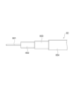
- the cable 60 may be a cable that is not specially shielded to reduce the influence of noise. More specifically, the cable 60 may be a coaxial cable as shown in FIG. 3, for example.
- This coaxial cable consists of a core wire 601 through which the digital signal output from the amplification converter 23 propagates, an insulator 602 that covers the core wire 601, a shield 603 that covers the insulator 602, and a jacket 604 that covers the shield 603.
- the shield 603 is made of a conductor, for example, and reduces the influence of noise on the core wire 601.
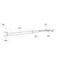
- the cable 60 may be a twisted pair cable as shown in FIG.
- This twisted pair cable includes a pair of core wires 611 twisted together through which a digital signal output from the amplification converter 23 propagates, an insulator 612 that covers the pair of core wires 611, and a shield 613 that covers the insulator 612. It consists of a jacket 614 that covers a shield 613.
- the shield 613 is made of a conductor, for example, and reduces the influence of noise on the pair of core wires 611.
- the cable 60 shown in FIG. 4 has one or more layers of shielding to reduce the influence of noise on the pair of core wires 611, and has been subjected to a special shielding process to reduce the influence of noise. There is no cable.
- control unit 30 has a power supply section 35, a driver section 31, an arithmetic processing section 32, a control section 33, and a memory 34 as main functional blocks.
- the power supply unit 35 is connected to an external power supply 40, and supplies power supplied from the external power supply 40 to the driver unit 31, the arithmetic processing unit 32, the control unit 33, the memory 34, and the like.
- the driver section 31 is connected to the driver section 27 of the load cell unit 20 via a cable 60, and receives the digital signal output from the driver section 27 of the load cell unit 20. For example, when the driver section 31 receives a digital signal as serial data, it may convert this into parallel data. The driver section 31 outputs a digital signal to the arithmetic processing section 32.
- the arithmetic processing unit 32 is composed of, for example, a CPU, and converts the input digital signal into digital data, and refers to various tables stored in the memory 34 to convert this digital data into various types of the subject 100. Convert it into analog data indicating the properties (e.g. tensile strength, compressive strength, etc.) of The arithmetic processing section 32 outputs this analog data to the control section 33.
- the memory 34 includes ROM (Read Only Memory), RAM (Random Access Memory), and the like.
- the control unit 33 is composed of, for example, a CPU, and controls the material testing machine 1. Specifically, the control unit 33 stores the analog data input from the arithmetic processing unit 32 in the memory 34, reads out the analog data stored in the memory 34 as necessary, and displays the analog data on a display or the like. It displays on the display section 50 configured and controls the operation of the drive section 16 shown in FIG.
- control unit 30 processes the digital signal output from the amplification conversion section 23 of the load cell unit 20, and displays and manages the data detected by the measurement section 22 of the load cell unit 20.
- control section 33 may issue control instructions to the load cell unit 20.
- the control section 33 creates a control instruction for the load cell unit 20 and outputs the control instruction to the arithmetic processing section 32 .
- control instruction referred to here is, for example, an instruction for zero/span adjustment to the arithmetic processing section 26 of the load cell unit 20. This is an instruction to the measurement unit 22 to start or end measurement.
- the arithmetic processing unit 32 converts the control instruction received from the control unit 33 into a control signal, and outputs the control signal to the driver unit 31.
- the driver section 31 outputs the control signal etc. received from the arithmetic processing section 32 to the driver section 27 of the load cell unit 20.
- the material testing machine 1 includes (i) the measurement unit 22 that converts the force applied to the subject 100 into an electrical signal, and (ii) the amplification unit that amplifies this electrical signal.
- the amplification/conversion section 23 includes a section 24 and an AD conversion section 25 that digitizes the amplified electrical signal, and the amplification/conversion section 23 is configured integrally with the measurement section 22 .
- the electrical signal generated in the measuring section 22 is converted into a digital signal before being output from the load cell unit 20 to the cable 60 (that is, within the load cell unit 20). converted.
- the electrical signal may be affected by noise while propagating through the cable 60.
- the electrical signal is an analog signal, there is a risk that a non-negligible error may occur between the data indicated by the analog signal that has reached the control unit 30 and the data measured by the measurement unit 22 due to the influence of noise. .
- the material testing machine 1 according to the present embodiment, the data measured by the measuring section 22 is converted into a digital signal within the load cell unit 20 and then conveyed to the control unit 30. Therefore, compared to the case where the analog signal is transmitted to the control unit 30 as it is, the influence of noise on the electrical signal generated in the measuring section 22 is reduced. Therefore, according to the material testing machine 1, it is possible to reduce the frequency of occurrence of an error between the data measured by the measurement unit 22 and the data processed by the control unit 30, and/or the error itself. In addition, in such a material testing machine 1, additional filter processing is performed on the analog signal outputted by the measurement section 22 and/or a digital signal outputted from the amplification conversion section 23, and additional shielding is applied to various wirings including the cable 60. By performing processing, it is possible to further reduce the influence of noise. Thereby, the material testing machine 1 can obtain even more reliable measurement data (that is, measurement data with high stability and accuracy).
- the influence of noise on the cable 60 is reduced. Therefore, according to the material testing machine 1, highly reliable measurement data can be obtained regardless of the structure or material of the cable used. For example, cables that have not been specially shielded to reduce the effects of noise (for example, cables with only one layer of shielding or one-way shielding) cannot be easily processed by conventional material testing machines. In view of this, it was difficult to use.
- the material testing machine 1 even when a type of cable such as this, which is difficult to use with conventional material testing machines, is used as the cable 60, the influence of noise can be reduced and reliability can be improved. It is possible to obtain high-quality measurement data.
- a specially shielded cable i.e., a relatively expensive cable
- the manufacturing cost of the material testing machine 1 as a whole is reduced. Is possible.
- the signal output from the load cell unit 20 is also AC, so it is more susceptible to the parasitic capacitance of the cable 60 than when the signal is DC. Moreover, this parasitic capacitance increases as the cable 60 becomes longer. As described above, when the signal is alternating current, the influence of noise caused by the parasitic capacitance of the cable 60 can become large. However, as described above, according to the material testing machine 1, the electrical signal from the measuring section 22 is converted into a digital signal within the load cell unit 20, so even if the signal is alternating current, such parasitic capacitance The effects of noise caused by this are reduced.
- the material testing machine 1 even if the measurement section 22 and the amplification conversion section 23 of the load cell unit 20 are driven with alternating current, it is possible to obtain highly reliable measurement data (that is, measurement data with high stability and accuracy). I can do it. That is, according to the material testing machine 1, AC drive can be realized while reducing the disadvantages of AC drive of the load cell unit 20.
- alternating current for example, when forcibly cutting off the current supply to the load cell unit 20, it is possible to cut off the current at the timing of the zero point of the current, and the material testing machine 1 It is possible to enjoy the effects of suppressing the load on the electrical system, etc.
- the influence of the parasitic capacitance can be further reduced by using the cable 60 as a twisted pair cable as shown in FIG. 4, for example.
- the influence of parasitic capacitance can be reduced by using the cable 60 as a twisted pair cable.
- the material testing machine 1 when the movable crosshead 11 is at the upper limit position 10U (highest reached position), that is, when the distance between the movable crosshead 11 and the control unit 30 is the farthest, , there is a deflection in the cable 60. Therefore, according to the material testing machine 1, it is possible to prevent excessive tensile force from being applied to the cable 60 when the moving crosshead 11 reaches the upper limit position 10U. By the way, it is generally expected that the longer the cable length of the material testing machine, the greater the influence of noise. Therefore, when the cable of the material testing machine has the above-mentioned flexure, the influence of noise may increase compared to when there is no flexure in the cable of the material testing machine. However, in the material testing machine 1, since the influence of noise is reduced as described above, it is possible to give the cable 60 such flexure while reducing the influence of noise.
- FIG. 5 is a diagram schematically showing the material testing machine of this embodiment.
- the material testing machine 2 of the present embodiment is the material testing machine of the first embodiment, except that the configuration of the load cell unit is different from the load cell unit 20 of the material testing machine 1 of the first embodiment. It has roughly the same configuration as 1. Therefore, regarding the material testing machine 2, the points related to the load cell unit will be explained below, and the other components will be given the same reference numerals as in the first embodiment, and the explanation will be omitted.
- the load cell unit 120 of this embodiment includes a load cell 140 attached to the main surface 11D of the movable crosshead 11 on the base 12 side, and a main surface 11U of the movable crosshead 11 on the top surface 15 side. It has a signal processing unit 150 attached to.
- the load cell 140 having the measuring section 142 described later and the signal processing unit 150 having the amplifying section 154 and AD converting section 155 described later are configured separately. . Both the load cell 140 and the signal processing unit 150 are fixed to the moving crosshead 11.
- the load cell 140 has a case 141, and electronic components constituting various functional blocks of the load cell 140, which will be described later, are stored or mounted in the case 141.
- the signal processing unit 150 has a case 151, and electronic components constituting various functional blocks of the signal processing unit 150, which will be described later, are stored or mounted in the case 151.
- the load cell 140 and the signal processing unit 150 are connected by a wiring 121.
- the length of the wiring 121 is extremely short compared to the cable 60.
- the wiring 121 may be less than or equal to the length of the second section 62 of the cable 60, and further may be less than or equal to the length of the first section 61 of the cable 60. Since the load cell 140 and the signal processing unit 150 are both fixed to the moving crosshead 11, they are placed close enough to each other that they can be connected by the wiring 121, which is extremely short compared to the length of the cable 60.
- the signal processing unit 150 is fixed to the moving crosshead 11 via a cushioning material 122.
- a cushioning material 122 rubber for vibration isolation and/or earthquake resistance can be used as the cushioning material 122. More specifically, for example, urethane rubber, silicone rubber, foam rubber of these rubbers, or the like can be used as the cushioning material 122.
- the shape of the cushioning material 122 is not particularly limited, the cushioning material 122 may have a mat-like shape, for example.
- FIG. 6 is a block diagram mainly showing functional blocks of the load cell unit 120 and the control unit 30 of the material testing machine 2.
- the load cell 140 has a measuring section 142, a memory 143, and a connector 144 as main functional blocks. Note that each part of the load cell 140 is driven by power obtained from the signal processing unit 150 via the connector 144.
- the measurement unit 142 is driven by direct current or alternating current.
- One end of the wiring 121 described above is connected to the connector 144 .
- the measuring section 142 includes a strain gauge. Furthermore, the first jig 17 configuring the test jig 19 is connected to the measurement section 142 . Therefore, as the movable crosshead 11 moves and the test jig 19 pulls or compresses the subject 100, strain occurs in the strain gauge of the measuring section 142.
- This strain gauge is part of a Wheatstone bridge circuit, and through this Wheatstone bridge circuit, changes in resistance due to strain occurring in the strain gauge are converted into voltage. A voltage signal (electrical signal) from this measuring section 142 is output to a connector 144.
- the memory 143 includes ROM, RAM, etc., and stores data (table) for calibrating the material testing machine 2.
- the memory 143 stores a table that associates the input voltage to the Wheatstone bridge circuit in the load cell 140 equipped with the memory 143 with the output voltage of the Wheatstone bridge circuit with respect to the input voltage.
- This memory 143 is connected to a connector 144.
- the signal processing unit 150 has, for example, a power supply section 158, a measurement section voltage generation section 153, an amplification conversion section 159, an arithmetic processing section 156, a driver section 157, and a connector 152 as main functional blocks. are doing.
- the power supply section 158 supplies direct current or alternating current power supplied from the external power source 40 to a measurement section voltage generation section 153, an amplification conversion section 159 (that is, an amplification section 154 and an AD conversion section 155 described later), and an AD conversion section. 155, an arithmetic processing section 156, a driver section 157, and the like. That is, the amplification conversion section 159 is driven by direct current or alternating current.
- the power supply section 158 converts the power supplied from the external power source 40 into direct current and alternating current, etc., and supplies the power from the external power source 40 to the measurement section voltage generation section 153, the amplification conversion section 159, and the arithmetic processing section 156. , and the driver unit 157 may convert it into usable power.
- the measurement unit voltage generation unit 153 converts the power supplied from the power supply unit 158 into power that can be used by the measurement unit 142 (and memory 143) of the load cell 140.
- the measurement unit voltage generation unit 153 supplies the converted power to the load cell 140 via the connector 152. Note that if the measurement section 142 (and memory 143) can directly use the power supplied from the power supply section 158, the measurement section voltage generation section 153 is not an essential configuration in the material testing machine 2.
- the other end of the wiring 121 described above is connected to the connector 152. Therefore, the electrical signal from the measurement section 142 of the load cell 140 and the data from the memory 143 are input to the connector 152 via the connector 144 of the load cell 140 and the wiring 121.
- the connector 152 outputs the input electrical signal and/or data to the amplification conversion section 159. Furthermore, the connector 152 outputs the electric power input from the measuring section voltage generation section 153 to the connector 144 of the load cell 140. As a result, power is supplied to the load cell 140.
- the amplification/conversion section 159 includes an amplification section 154 and an AD conversion section 155.
- the amplifying section 154 amplifies the electrical signal input from the measuring section 142 of the load cell 140 and outputs the amplified electrical signal to the AD converting section 155.
- the AD conversion section 155 then converts the amplified electrical signal into a digital signal and outputs this digital signal to the arithmetic processing section 156.
- the signal processing unit 150 is configured separately from the measurement section 142, and is connected to the measurement section 142 via the connector 152 and the connector 144. Further, the signal processing unit 150 is arranged near the measuring section 142 (that is, near the load cell 140).
- the specific distance of "nearby” here is not particularly limited, but the distance between the load cell 140 and the signal processing unit 150 is longer than the distance from the signal processing unit 150 to the control unit 30. It is desirable that the length is also short.
- the arithmetic processing section 156 of the signal processing unit 150 is composed of, for example, a CPU.
- the arithmetic processing unit 156 reads data (table) for calibrating the material testing machine 2 described above from the memory 143 of the load cell 140, and refers to this table. , calibrates the voltage value indicated by the digital signal input from the AD converter 155 to a predetermined voltage value. That is, the arithmetic processing unit 156 calibrates the material testing machine 2 based on the data from the memory 143. The arithmetic processing unit 156 then outputs the calibrated digital signal to the driver unit 157.
- the arithmetic processing unit 156 may calibrate the electrical signal output from the connector 152 before the electrical signal is processed in the amplification unit 154 and the AD conversion unit 155. Further, the arithmetic processing section 156 may control each section of the load cell unit 120 in an integrated manner. In this case, the arithmetic processing section 156 may control the load cell unit 120 according to a control instruction from the control unit 30.
- a cable 60 is connected to the driver section 157.
- Driver section 157 outputs a digital signal to cable 60.
- the driver section 157 transmits the digital signal input from the arithmetic processing section 156 (or a signal obtained by converting the digital signal) to the cable 60 in a format according to the communication form between the signal processing unit 150 and the control unit 30.
- Output For example, the driver section 157 outputs a digital signal to the cable 60 as serial data such as RS-232C or RS-422/485. Then, similarly to the material testing machine 1 of the first embodiment, this serial data is transmitted through the cable 60 and input to the driver section 31 of the control unit 30.
- the material testing machine 2 includes the measuring section 142 that converts the force applied to the subject 100 into an electrical signal, the amplifying section 154 that amplifies this electrical signal, and the amplifying section 154.
- An amplification/conversion section 159 including an AD conversion section 155 that digitizes the amplified electrical signal, and the amplification/conversion section 159 is configured separately from the measurement section 142 and is located near the measurement section 142. It is located.
- the electrical signal generated in the measuring section 142 is converted into a digital signal before being output from the load cell unit 120 to the cable 60 (that is, within the load cell unit 120). converted.
- the amplification conversion section 159 is configured separately from the measurement section 142, but since the amplification conversion section 159 is arranged near the measurement section 142 as described above, the measurement section The electrical signal generated at 142 is hardly affected by noise when propagating through the wiring 121.
- the data measured by the measurement section 142 is converted into a digital signal by the amplification conversion section 159, and then transmitted to the control unit 30.
- the influence of noise on the electrical signal generated by the measurement unit 142 is reduced compared to the case where the data measured by the measurement unit 142 is conveyed to the control unit 30 as an analog signal. Therefore, according to the material testing machine 2, it is possible to reduce the frequency of occurrence of an error between the data measured by the measurement unit 142 and the data processed by the control unit 30, and/or the error itself. Further, by performing filter processing or shield processing on such material testing machine 2, it is possible to further reduce the influence of noise. Thereby, the material testing machine 2 can obtain even more reliable measurement data (that is, measurement data with high stability and accuracy).
- the influence of noise is reduced as described above. Therefore, according to the material testing machine 2, highly reliable measurement data can be obtained regardless of the structure or material of the cable used. For example, cables that have not been specially shielded to reduce the effects of noise (for example, cables with only one layer of shielding or cables with one-way shielding) cannot be easily processed by conventional material testing machines. In view of this, it was difficult to use.
- the material testing machine 2 even when a type of cable such as this, which is difficult to use with conventional material testing machines, is used as the cable 60, the influence of noise can be reduced and reliability can be improved. It is possible to obtain high-quality measurement data.
- a cable with special shielding processing as described above i.e., a relatively expensive cable
- the material testing machine 2 similarly to the material testing machine 1, the influence of noise caused by the parasitic capacitance of the cable 60 is reduced. Therefore, in the material testing machine 2, it is relatively easy to drive the load cell unit 120 with alternating current.
- the influence of the parasitic capacitance can be further reduced by using the cable 60 as a twisted pair cable as shown in FIG. 4, for example.
- the influence of parasitic capacitance can be reduced by using the cable 60 as a twisted pair cable.
- the material testing machine 2 similarly to the first embodiment, when the movable crosshead 11 is at the upper limit position 10U (highest reached position), that is, the distance between the movable crosshead 11 and the control unit 30 is at its maximum. At the far end, there is a flex in the cable 60. Therefore, according to the material testing machine 2, it is possible to prevent excessive tensile force from being applied to the cable 60 when the moving crosshead 11 reaches the upper limit position 10U.
- the load cell 140 including the measuring section 142 has the memory 143 storing data for calibrating the material testing machine 2, and the signal processing unit
- the arithmetic processing unit 156 of the load cell 150 reads the above data from the memory 143 of the load cell 140 when the load cell 140 is connected to the signal processing unit 150, and calibrates the material testing machine 2. That is, the load cell unit 120 of the material testing machine 2 has a so-called plug-and-play function. With such a configuration, when the load cell 140 is replaced with a new load cell 140, the effort of manually calibrating the new load cell 140 to make it compatible with the material testing machine 2 can be omitted. However, it is not essential that the load cell unit 120 has a plug-and-play function.
- the material testing machine 2 has a configuration in which a signal processing unit 150 including an amplification conversion section 159 is fixed to the moving crosshead 11 via a cushioning material 122. With such a configuration, it is possible to suppress vibrations and shocks from the moving crosshead 11 from being transmitted to the substrate on which the amplifying section 154 and the AD converting section 155 are mounted.
- the cushioning material 122 is not essential.
- the load cell 140 is fixed to the main surface 11D of the movable crosshead 11 on the base 12 side
- the signal processing unit 150 is fixed to the main surface 11U of the movable crosshead 11 on the top surface 15 side.
- the signal processing unit 150 may be fixed to the main surface 11D and the load cell 140 may be fixed to the main surface 11U, or the load cell 140 and the signal processing unit 150 may be fixed to one of the main surfaces 11U and 11D. Both may be fixed.
- the material testing machine is a tensile compression tester
- the present invention also applies to other types of material testing machines (for example, a torsion testing machine or a vibration testing machine). It is also possible to apply it to machines, etc.).
Landscapes
- Analytical Chemistry (AREA)
- Physics & Mathematics (AREA)
- Health & Medical Sciences (AREA)
- Life Sciences & Earth Sciences (AREA)
- Chemical & Material Sciences (AREA)
- Biochemistry (AREA)
- General Health & Medical Sciences (AREA)
- General Physics & Mathematics (AREA)
- Immunology (AREA)
- Pathology (AREA)
- Manufacturing & Machinery (AREA)
- Engineering & Computer Science (AREA)
- Investigating Strength Of Materials By Application Of Mechanical Stress (AREA)
Abstract
Description
図1は、本実施形態の材料試験機を模式的に示す図である。図1に示すように、本実施形態の材料試験機1は、引張圧縮試験機であり、基台12と、基台12と平行な天面15と、1対のフレーム10A,10Bと、移動クロスヘッド11と、ロードセルユニット20と、制御ユニット30と、を主な構成として備えている。材料試験機1は、基台12が鉛直方向下方に、天面15が鉛直方向上方に向けられた状態で使用される。
次に、第2実施形態に係る材料試験機について説明する。図5は、本実施形態の材料試験機を模式的に示す図である。図5に示すように、本実施形態の材料試験機2は、ロードセルユニットの構成が第1実施形態の材料試験機1のロードセルユニット20と異なる点を除いて、第1実施形態の材料試験機1と概ね同様の構成を有する。したがって、以下、材料試験機2については、ロードセルユニットに関連する点を説明し、その他の構成については第1実施形態と同様の符号を付して説明を省略する。
Claims (12)
- 被検体に対して材料試験を行うための材料試験機であって、
前記被検体に印加される力を電気信号に変換する測定部と、
前記電気信号を増幅する増幅部と前記増幅部で増幅された前記電気信号をデジタル化するAD変換部とを含む増幅変換部と、
を備え、
前記増幅変換部は、前記測定部と一体に構成されている、又は、前記測定部とは別体に構成されて前記測定部の近傍に配置されている
ことを特徴とする材料試験機。 - 前記増幅変換部は、前記測定部と一体に構成されている
ことを特徴とする請求項1に記載の材料試験機。 - 前記増幅変換部は、前記測定部と別体に構成されて前記測定部に接続され、
前記測定部及び前記増幅変換部は、前記材料試験機の移動クロスヘッドに固定されている
ことを特徴とする請求項1に記載の材料試験機。 - 前記増幅変換部は、緩衝材を介して前記移動クロスヘッドに固定される
ことを特徴とする請求項3に記載の材料試験機。 - 前記増幅変換部は、前記移動クロスヘッドの天面に固定されている
ことを特徴とする、請求項3又は4に記載の材料試験機。 - 前記測定部及び前記増幅変換部は、交流で駆動する
ことを特徴とする請求項1から5のいずれか1項に記載の材料試験機。 - 前記増幅変換部と当該増幅変換部から出力されるデジタル信号を処理する制御ユニットとを接続するケーブルをさらに備える
ことを特徴とする請求項1から6のいずれか1項に記載の材料試験機。 - 前記ケーブルは、心線と当該心線に対するノイズの影響を低減する1層以上のシールドとを有する
ことを特徴とする請求項7に記載の材料試験機。 - 前記ケーブルは、ツイストペアケーブルである
ことを特徴とする請求項7又は8に記載の材料試験機。 - 前記ケーブルは、前記材料試験機の移動クロスヘッドと前記制御ユニットとの距離が最も遠いときにたわみが生じるように配線される
ことを特徴とする請求項7から9のいずれか1項に記載の材料試験機。 - 前記増幅変換部と一体に構成された演算処理部を備え、
前記測定部は、前記材料試験機をキャリブレーションするためのデータが格納されたメモリを有するロードセルに含まれており、
前記演算処理部は、前記ロードセルが前記増幅変換部に接続された際に前記ロードセルの前記メモリから前記データを読み出して、前記材料試験機をキャリブレーションする
ことを特徴とする、請求項1から10のいずれか1項に記載の材料試験機。 - 前記材料試験機は、前記被検体に対して引張試験及び圧縮試験を行うための引張圧縮試験機である
ことを特徴とする請求項1から11のいずれか1項に記載の材料試験機。
Priority Applications (2)
| Application Number | Priority Date | Filing Date | Title |
|---|---|---|---|
| CN202380057645.6A CN119630952A (zh) | 2022-08-03 | 2023-06-09 | 材料试验机 |
| KR1020257001361A KR20250042743A (ko) | 2022-08-03 | 2023-06-09 | 재료시험기 |
Applications Claiming Priority (2)
| Application Number | Priority Date | Filing Date | Title |
|---|---|---|---|
| JP2022124190A JP2024021394A (ja) | 2022-08-03 | 2022-08-03 | 材料試験機 |
| JP2022-124190 | 2022-08-03 |
Publications (1)
| Publication Number | Publication Date |
|---|---|
| WO2024029201A1 true WO2024029201A1 (ja) | 2024-02-08 |
Family
ID=89848789
Family Applications (1)
| Application Number | Title | Priority Date | Filing Date |
|---|---|---|---|
| PCT/JP2023/021566 Ceased WO2024029201A1 (ja) | 2022-08-03 | 2023-06-09 | 材料試験機 |
Country Status (4)
| Country | Link |
|---|---|
| JP (1) | JP2024021394A (ja) |
| KR (1) | KR20250042743A (ja) |
| CN (1) | CN119630952A (ja) |
| WO (1) | WO2024029201A1 (ja) |
Citations (2)
| Publication number | Priority date | Publication date | Assignee | Title |
|---|---|---|---|---|
| US7791254B1 (en) * | 2006-11-27 | 2010-09-07 | William Gordon Gibson | Hybrid ultrasound transducer |
| JP2019219336A (ja) * | 2018-06-22 | 2019-12-26 | 株式会社島津製作所 | 変位計 |
Family Cites Families (1)
| Publication number | Priority date | Publication date | Assignee | Title |
|---|---|---|---|---|
| JP6658383B2 (ja) | 2016-07-27 | 2020-03-04 | 株式会社島津製作所 | 材料試験機 |
-
2022
- 2022-08-03 JP JP2022124190A patent/JP2024021394A/ja active Pending
-
2023
- 2023-06-09 CN CN202380057645.6A patent/CN119630952A/zh active Pending
- 2023-06-09 KR KR1020257001361A patent/KR20250042743A/ko active Pending
- 2023-06-09 WO PCT/JP2023/021566 patent/WO2024029201A1/ja not_active Ceased
Patent Citations (2)
| Publication number | Priority date | Publication date | Assignee | Title |
|---|---|---|---|---|
| US7791254B1 (en) * | 2006-11-27 | 2010-09-07 | William Gordon Gibson | Hybrid ultrasound transducer |
| JP2019219336A (ja) * | 2018-06-22 | 2019-12-26 | 株式会社島津製作所 | 変位計 |
Non-Patent Citations (1)
| Title |
|---|
| ANONYMOUS: "KUBOTA Digital Load Cell", KUBOTA TECHNICAL REPORT, KUBOTA CORPORATION, 1 October 2020 (2020-10-01), pages 3 - 4, XP009553523 * |
Also Published As
| Publication number | Publication date |
|---|---|
| CN119630952A (zh) | 2025-03-14 |
| JP2024021394A (ja) | 2024-02-16 |
| KR20250042743A (ko) | 2025-03-27 |
Similar Documents
| Publication | Publication Date | Title |
|---|---|---|
| JP5003387B2 (ja) | 車両のシート用乗員荷重センサのノイズシールド構造 | |
| JP5003385B2 (ja) | 車両のシート用乗員荷重検出装置 | |
| JP2009539116A (ja) | 変位、歪および力センサ | |
| JP2003035639A (ja) | 圧縮バネの特性試験方法および装置 | |
| CN201837364U (zh) | 一种拉压应变式传感器 | |
| WO2024029201A1 (ja) | 材料試験機 | |
| JP3874490B2 (ja) | 高速引張試験における計測方法 | |
| CN101995209B (zh) | 架空导线弯曲幅度传感器 | |
| JP5996546B2 (ja) | 圧電センサ及び断熱部を備えた接触式プローブ | |
| US8960024B2 (en) | Diaphragm type displacement sensor detecting moment | |
| CN208187598U (zh) | 测力传感器及动力总成悬置力测量传感器 | |
| JP5149081B2 (ja) | ひずみ量測定機能付き締結具 | |
| CN218973722U (zh) | 一种力传感器检定校准装置 | |
| JPH0229179B2 (ja) | Denshibakari | |
| CN212238070U (zh) | 一种高稳定性磁致伸缩换能器 | |
| JP2013108792A (ja) | ロードセル | |
| JP2005037298A (ja) | センサ付転動装置 | |
| CN115575236A (zh) | 一种插入式弹性结构内腔机械性能测量装置及方法 | |
| JP2004045138A (ja) | 分力計 | |
| KR20080094522A (ko) | 지지하중이 표시되는 레벨링장치 | |
| JP3060259B2 (ja) | 3分力計 | |
| JPH11295162A (ja) | ロードセル式計量装置およびロードセル | |
| RU2618496C1 (ru) | Датчик ускорения | |
| JP3357896B2 (ja) | 車両用変速機のチェンジレバー操作力検出装置 | |
| JPH0815057A (ja) | 薄型ロードセル |
Legal Events
| Date | Code | Title | Description |
|---|---|---|---|
| 121 | Ep: the epo has been informed by wipo that ep was designated in this application |
Ref document number: 23849761 Country of ref document: EP Kind code of ref document: A1 |
|
| WWE | Wipo information: entry into national phase |
Ref document number: 2501000651 Country of ref document: TH |
|
| WWE | Wipo information: entry into national phase |
Ref document number: 202380057645.6 Country of ref document: CN |
|
| NENP | Non-entry into the national phase |
Ref country code: DE |
|
| WWP | Wipo information: published in national office |
Ref document number: 202380057645.6 Country of ref document: CN |
|
| WWP | Wipo information: published in national office |
Ref document number: 1020257001361 Country of ref document: KR |
|
| 122 | Ep: pct application non-entry in european phase |
Ref document number: 23849761 Country of ref document: EP Kind code of ref document: A1 |