WO2024029142A1 - センシング装置およびセンシング方法 - Google Patents
センシング装置およびセンシング方法 Download PDFInfo
- Publication number
- WO2024029142A1 WO2024029142A1 PCT/JP2023/015838 JP2023015838W WO2024029142A1 WO 2024029142 A1 WO2024029142 A1 WO 2024029142A1 JP 2023015838 W JP2023015838 W JP 2023015838W WO 2024029142 A1 WO2024029142 A1 WO 2024029142A1
- Authority
- WO
- WIPO (PCT)
- Prior art keywords
- information
- far
- infrared
- distance information
- partial surface
- Prior art date
- Legal status (The legal status is an assumption and is not a legal conclusion. Google has not performed a legal analysis and makes no representation as to the accuracy of the status listed.)
- Ceased
Links
Images

Classifications
-
- G—PHYSICS
- G01—MEASURING; TESTING
- G01B—MEASURING LENGTH, THICKNESS OR SIMILAR LINEAR DIMENSIONS; MEASURING ANGLES; MEASURING AREAS; MEASURING IRREGULARITIES OF SURFACES OR CONTOURS
- G01B11/00—Measuring arrangements characterised by the use of optical techniques
- G01B11/24—Measuring arrangements characterised by the use of optical techniques for measuring contours or curvatures
- G01B11/245—Measuring arrangements characterised by the use of optical techniques for measuring contours or curvatures using a plurality of fixed, simultaneously operating transducers
-
- G—PHYSICS
- G01—MEASURING; TESTING
- G01B—MEASURING LENGTH, THICKNESS OR SIMILAR LINEAR DIMENSIONS; MEASURING ANGLES; MEASURING AREAS; MEASURING IRREGULARITIES OF SURFACES OR CONTOURS
- G01B11/00—Measuring arrangements characterised by the use of optical techniques
- G01B11/24—Measuring arrangements characterised by the use of optical techniques for measuring contours or curvatures
-
- G—PHYSICS
- G06—COMPUTING OR CALCULATING; COUNTING
- G06T—IMAGE DATA PROCESSING OR GENERATION, IN GENERAL
- G06T5/00—Image enhancement or restoration
- G06T5/50—Image enhancement or restoration using two or more images, e.g. averaging or subtraction
-
- G—PHYSICS
- G06—COMPUTING OR CALCULATING; COUNTING
- G06T—IMAGE DATA PROCESSING OR GENERATION, IN GENERAL
- G06T7/00—Image analysis
- G06T7/50—Depth or shape recovery
- G06T7/55—Depth or shape recovery from multiple images
- G06T7/564—Depth or shape recovery from multiple images from contours
-
- G—PHYSICS
- G06—COMPUTING OR CALCULATING; COUNTING
- G06T—IMAGE DATA PROCESSING OR GENERATION, IN GENERAL
- G06T7/00—Image analysis
- G06T7/50—Depth or shape recovery
- G06T7/55—Depth or shape recovery from multiple images
- G06T7/586—Depth or shape recovery from multiple images from multiple light sources, e.g. photometric stereo
-
- G—PHYSICS
- G06—COMPUTING OR CALCULATING; COUNTING
- G06T—IMAGE DATA PROCESSING OR GENERATION, IN GENERAL
- G06T7/00—Image analysis
- G06T7/50—Depth or shape recovery
- G06T7/55—Depth or shape recovery from multiple images
- G06T7/593—Depth or shape recovery from multiple images from stereo images
-
- G—PHYSICS
- G06—COMPUTING OR CALCULATING; COUNTING
- G06T—IMAGE DATA PROCESSING OR GENERATION, IN GENERAL
- G06T7/00—Image analysis
- G06T7/70—Determining position or orientation of objects or cameras
- G06T7/73—Determining position or orientation of objects or cameras using feature-based methods
-
- G—PHYSICS
- G06—COMPUTING OR CALCULATING; COUNTING
- G06T—IMAGE DATA PROCESSING OR GENERATION, IN GENERAL
- G06T7/00—Image analysis
- G06T7/80—Analysis of captured images to determine intrinsic or extrinsic camera parameters, i.e. camera calibration
- G06T7/85—Stereo camera calibration
-
- G—PHYSICS
- G06—COMPUTING OR CALCULATING; COUNTING
- G06V—IMAGE OR VIDEO RECOGNITION OR UNDERSTANDING
- G06V10/00—Arrangements for image or video recognition or understanding
- G06V10/40—Extraction of image or video features
- G06V10/44—Local feature extraction by analysis of parts of the pattern, e.g. by detecting edges, contours, loops, corners, strokes or intersections; Connectivity analysis, e.g. of connected components
-
- G—PHYSICS
- G06—COMPUTING OR CALCULATING; COUNTING
- G06T—IMAGE DATA PROCESSING OR GENERATION, IN GENERAL
- G06T2207/00—Indexing scheme for image analysis or image enhancement
- G06T2207/10—Image acquisition modality
- G06T2207/10004—Still image; Photographic image
- G06T2207/10012—Stereo images
-
- G—PHYSICS
- G06—COMPUTING OR CALCULATING; COUNTING
- G06T—IMAGE DATA PROCESSING OR GENERATION, IN GENERAL
- G06T2207/00—Indexing scheme for image analysis or image enhancement
- G06T2207/10—Image acquisition modality
- G06T2207/10048—Infrared image
-
- G—PHYSICS
- G06—COMPUTING OR CALCULATING; COUNTING
- G06T—IMAGE DATA PROCESSING OR GENERATION, IN GENERAL
- G06T2207/00—Indexing scheme for image analysis or image enhancement
- G06T2207/30—Subject of image; Context of image processing
- G06T2207/30108—Industrial image inspection
- G06T2207/30164—Workpiece; Machine component
Definitions
- the present invention relates to a sensing device and a sensing method.
- the camera often uses a visible light sensor, and the three-dimensional shape of the workpiece packed with paper or other materials can be accurately recognized.
- a transparent material such as a blister pack
- the shape of the packaged part cannot be acquired, but only the shape of the workpiece inside. There is a risk of crushing and destroying it. Therefore, a method that uses not only a visible light sensor but also a far-infrared camera is expected to obtain the three-dimensional shape of the transparent part.
- a three-dimensional shape is obtained by measuring a workpiece from a plurality of locations using an imaging device having a fixed visible light camera and a far-infrared camera.
- Patent Document 1 If the technology of Patent Document 1 is utilized, it is possible to correctly recognize the shape of the transparent part of a work whose main body is packed with a transparent material, and it is possible to pick the work without destroying the packaged part. However, moving the imaging device to acquire multiple images not only depends on the accuracy of calibration, but also takes time to pick one workpiece, reducing the efficiency of the entire system. There is a fear.
- the present invention has been made in view of the above problems, and its purpose is to provide a sensing device and a sensing method that can accurately measure the three-dimensional shape of an object containing a transparent material.
- the present invention provides a sensing device for measuring a three-dimensional shape of an object, which includes a computer and a heating device, and the computer generates an image based on visual information of the object.
- a generation unit an object area extraction unit that extracts an area occupied by the object from the image as an object area; and an object area extraction unit that extracts distance information of an edge portion of the object from among the distance information of the object to generate edge distance information.
- an edge distance information generation section ; a far-infrared image generation section that generates a far-infrared image corresponding to the object region based on far-infrared information of the object; and a heating device that controls the heating device to heat the object.
- the present invention includes a shape interpolation section that generates interpolated edge distance information, and an object shape output section that converts the interpolated edge distance information into three-dimensional shape information and outputs it.
- the steps include: generating an image of the object based on visual information of the object; extracting a region occupied by the object from the image as an object region; A step of extracting distance information of an edge portion of the object from distance information of the object to generate edge distance information; and a step of generating a far-infrared image corresponding to the object region based on far-infrared information of the object.
- a step of heating the object a step of generating a far-infrared image of the object after heating the object, and a step of estimating partial surface shape information of the object from the far-infrared image of the object before and after heating.
- partial surface shape information of an object is generated from far-infrared images before and after heating the object, and edge distance information of the object is interpolated using the partial surface shape information. It becomes possible to accurately measure the three-dimensional shape of objects including materials.
- Configuration diagram of a sensing device and a sensing system in a first embodiment of the present invention Functional block diagram of object region extraction section Diagram explaining the processing of the edge distance information generation unit A diagram showing an example of edge distance information generated by the edge distance information generation unit Diagram explaining the processing of the far-infrared image generation unit Diagram explaining the processing of the partial surface shape estimation unit
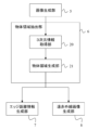
- FIG. 1 is a configuration diagram of a sensing device and a sensing system in a first embodiment of the present invention.
- a sensing device 100 shown in FIG. 1 is a device that measures the three-dimensional shape of an object, and includes a computer 1 and a heating device 4.
- the functions of functional units 5 to 12 of a computer 1 are realized in a computer 1 having an arithmetic unit, a main storage device, and an external storage device.
- the sensing device 100 measures the three-dimensional shape of an object based on the object's visual information, distance information, and far-infrared information. It is preferable to use a visible light sensor as a means for acquiring visual information and distance information about an object.
- the stereo camera 2 is used as a visible light sensor, but the visible light sensor is not limited to this.
- the sensing system 200 includes a sensing device 100, a visible light sensor 2, and a far-infrared sensor 3.
- the image generation unit 5 has a function of generating two images based on information acquired by the left and right visible light cameras of the stereo camera 2, and the object area extraction unit 6 analyzes the two images generated by the image generation unit 5.
- the edge distance information generation section 7 has a function of extracting the object region in the image by analyzing the distance information corresponding to the object region and extracts the distance information of the edge part of the object.
- the far-infrared camera 3 has a function of generating a far-infrared image corresponding to the object region
- the heating device control section 9 has a function of controlling the heating device 4 to heat the object region
- the partial surface shape estimating section 10 has a function of generating a far-infrared image corresponding to the object region.
- a function of analyzing far-infrared images of the object region before and after heating generated by the generation section 8 and estimating a part of the surface shape of the object region, and a shape interpolation section 11 uses the estimated surface shape to generate edge distance information.
- the function is to interpolate the edge distance information generated by the generation unit 7, and the object shape output unit 12 is a function to convert it into the interpolated three-dimensional shape information and output it.
- the details of the functional units 6 to 12 will be explained below.
- FIG. 2 is a functional block diagram of the object region extraction section 6.
- the object region extraction section 6 includes a three-dimensional information acquisition section 20 that acquires three-dimensional information from the captured image of the stereo camera 2 generated by the image generation section 5, and a three-dimensional information acquisition section 20 that analyzes the acquired three-dimensional information and extracts an object region in the image. and an object region extracting section 21.
- the three-dimensional information acquisition unit 20 acquires three-dimensional information by calculating parallax from images captured by the stereo camera 2.
- the parallax is calculated using a general method such as block matching.
- the calculated parallax information is converted into three-dimensional information such as point group information on a three-dimensional space from the parameters of the camera installation position and posture information.
- any method that can obtain three-dimensional information from two camera images is not particularly limited.
- the object region extraction unit 21 extracts an object region from the camera image and three-dimensional information.
- extraction methods include, for example, a method in which a difference region between a camera image in which an object exists and a background camera image photographed in advance without an object is extracted as an object region, or a There is a method of extracting the difference region between the dimensional information and the 3D information calculated when it does not exist as an object region, and a method of extracting the common part between the object region obtained from the image and the object region obtained from the 3D information as the final object. There are methods of extracting it as a region, and there are no particular limitations.
- FIG. 3 is a diagram illustrating the processing of the edge distance information generation unit 7.
- 30 is an example of an object to be picked by the robot (hereinafter referred to as a work)
- 31 is a portion of the packaging material of the work 30 made of paper material
- 32 is a transparent portion of the packaging material of the work 30.
- a part formed of a material (plastic, glass, etc.), 33 is a work body packed with packing materials 31 and 32, 34 is a pedestal on which the work 30 is placed when measuring with the sensing device 100, and 35 is a An example of an image captured by one of the visible light cameras 2 when the workpiece 30 on the pedestal 34 is captured by the stereo camera 2, 36 is an object region extracted from the captured image 35 by the object region extraction unit 6, and 37 is edge distance information Edge distance information generated by the generation unit 7 is shown.
- the edge distance information generation unit 7 generates edge distance information of the workpiece 30 by analyzing three-dimensional information within the object region 36. An example of a method for generating edge distance information will be described. First, a distance value from the stereo camera 2 at a position corresponding to each pixel of the captured image 35 is determined from three-dimensional information, and information in which each pixel is associated with the distance value is generated as a distance image. Next, the distance value of each pixel in the distance image is compared with the distance value of the adjacent pixels vertically, horizontally, and horizontally, and if there is a difference greater than a threshold value between the two, that pixel is extracted as an edge part, and the one with the smaller compared distance value is information that is associated with pixels of the edge portion is generated as edge distance information.
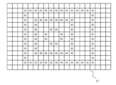
- FIG. 4 is a diagram showing an example of the edge distance information 37 generated by the edge distance information generation section 7.
- a distance value (unit: cm) from the camera is stored in each pixel of the edge portion, and no value is stored in each pixel other than the edge portion.
- the edge distance information 37 makes it possible to express the distance information of the outer part of the workpiece 30, and it is also possible to obtain the distance information of the outer frame of the transparent packaging materials 31 and 32. Note that there are no particular limitations on the method other than this example, as long as it is possible to obtain distance information corresponding to the edge portion of the workpiece 30. Further, regarding the resolution of the distance image, a resolution equivalent to that of the captured image may be used, or a distance image whose resolution has been lowered by downsampling processing or the like may be used.
- FIG. 5 is a diagram illustrating the processing of the far-infrared image generation section 8.
- 40 indicates a far-infrared image of the workpiece 30 and the pedestal 34 generated based on information from the far-infrared camera 3
- 41 indicates a far-infrared image corresponding to the object region 36 extracted from the far-infrared image 40.
- Far-infrared images include temperature information, and temperature information varies depending on the material.
- a far-infrared image is information in which a temperature value is associated with each pixel, and is treated as image information like a captured image or a distance image.
- the resolution of the far-infrared image is not particularly limited, and it may be the same as the captured image or one with a lower resolution.
- the heating device control section 9 heats the workpiece 30 using the heating device 4.
- the heating device 4 is installed close to the stereo camera 2 and the far-infrared camera 3, and the workpiece 30 is photographed in the same direction (right above the workpiece 30 in this example).
- the means can heat the workpiece 30 from the same direction as the direction in which the workpiece 30 is photographed.
- a hot air device is assumed as the heating device 4, but the device is not particularly limited as long as it is capable of promoting a rise in the temperature of the workpiece 30.
- the heating device control unit 9 sends a command to the far-infrared image generation unit 8 to measure the workpiece 30 again with the far-infrared camera 3. By doing so, far-infrared images of the workpiece 30 before and after heating are generated.
- the heating method by the heating device 4 includes heating each time for a preset time, and estimating the approximate distance from the heating device 4 to the object 30 by utilizing edge distance information and far-infrared images generated in advance.
- a method of adjusting the heating time or heating direction according to prior information (shape, dimensions, material, etc.) of the workpiece 30 may be used, and is not particularly limited.
- FIG. 6 is a diagram illustrating the processing of the partial surface shape estimation unit 10.
- 41 is an example of a far-infrared image corresponding to the work area (object area) before heating shown in FIG.
- Examples of images 44 and 45 show examples of partial surface shape information output by the partial surface shape estimating section 10.
- the heating device 4 is installed close to the far-infrared camera 3 and heats the workpiece 30 from directly above, so the higher the part of the workpiece 30 (the part closer to the far-infrared camera 3 or the stereo camera 2), the more , because it is heated quickly, the temperature change becomes large.
- the transparent packaging portion is located closest to the heating device 4, so the temperature of the transparent packaging portion, such as 42, is the highest. Furthermore, since the paper portion of the workpiece 30 itself is heated, a temperature change occurs and the area of the paper material can be measured. On the other hand, if the work body 33 is made of a material that does not easily heat up, the temperature will be lower than the transparent packaging part 42, making it impossible to measure the area of the work body 33. If there is, as shown in the far-infrared image 43, the area of the workpiece body 33 can be measured because the temperature is higher than that of the transparent packaging part.
- the region of the work body 33 in the far-infrared image 43 becomes noise. Therefore, it is possible to use the far-infrared image 41 generated before heating, and perform processing such as noise removal by deleting areas with temperature values above a threshold before heating from the far-infrared image 43 generated after heating. good.
- the partial surface shape estimating unit 10 outputs regions having similar temperature values as partial surface shape information 44 and 45 from the final heated far-infrared image 42 after noise removal and the like. Note that when extracting partial surface shape information, it is possible to use not only temperature values but also region position information, and if there are multiple regions with similar temperature values, these regions can be set to a predetermined threshold value. If the distance is greater than , it may be output as separate partial surface shape information, and there is no particular limitation.
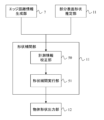
- FIG. 7 is a functional block diagram of the shape interpolation section 11.
- the shape interpolation unit 11 converts two pieces of measurement information, edge distance information generated based on information from the stereo camera 2 and partial surface shape information estimated based on information from the far-infrared camera 3, into information on the same sensor space. It includes a measurement information calibration section 50 that performs calibration, and a shape interpolation execution section 51 that compares the measurement information after calibration and interpolates the three-dimensional shape of the workpiece.
- the measurement information calibration section 50 and the shape interpolation execution section 51 will be explained below.
- the measurement information calibration unit 50 calibrates the edge distance information and the partial surface shape information into information on the same sensor space based on the installation positions, posture information, resolution information, etc. of the stereo camera 2 and the far-infrared camera 3.
- each measurement information is treated as image information, so after resizing the image so that the resolution matches one size, it was determined by a calibration method using a general check marker etc.
- Calibration is performed by converting the coordinate information of each measurement information into the same space using the rotation matrix and translation vector between the sensors.
- the resizing of the resolution there is no particular limitation on which resolution to match, edge distance information or partial surface shape information.
- the calibration method is not particularly limited as long as it is capable of coordinate transformation that allows the edge distance information shown in FIG. 4 to be compared with the partial surface shape information 44, 45 shown in FIG.
- a coordinate transformation method in a two-dimensional space such as alignment between images may be used.
- FIG. 8 is a diagram illustrating the processing of the shape interpolation execution unit 51.
- reference numeral 55 indicates an example of initial edge distance information in which distance values of edge portions are described in the edge distance information 37
- 56 and 57 indicate examples of interpolated edge distance information interpolated by the shape interpolation execution unit 51.
- the shape interpolation execution section 51 interpolates the initial edge distance information 55 using the partial surface shape information 44 and 45 calibrated by the measurement information calibrating section 50.
- the flow of interpolation is to compare the partial surface shape information 44, 45 with the edge distance information 37, and determine which edge portion of the edge distance information 37 the outer peripheral portion of each partial surface shape information corresponds to by a fitting process or the like. do.
- interpolation processing of the initial edge distance information 55 is performed while sequentially using the partial surface shape information located far from the stereo camera 2.
- the size of the partial surface shape information may be used.
- the distance value of the edge distance information corresponding to the outer periphery of the partial surface shape information is used as the reference distance value, and if there is a blank space around each pixel (at the top, bottom, left, or right), the reference distance value is filled in.
- the method uses the value of the initial edge distance information 55 to fill in the blank area, such as a method in which the process of repeating the above process within the object area until a pixel containing a distance value smaller than the reference distance value is found. do not.
- the distance value of the partial surface shape information 44 is 15 cm larger, so the initial edge distance is calculated using the partial surface shape information 44.
- the information 55 is interpolated to generate interpolated edge distance information 56.
- the interpolated edge distance information 56 is interpolated using the partial surface shape information 45 to generate interpolated edge distance information 57.
- the object shape output unit 12 generates a three-dimensional point group from the interpolated edge distance information generated by the shape interpolation unit 11, and outputs it as the final three-dimensional shape information of the workpiece.
- a sensing device 100 that measures the three-dimensional shape of an object 30 includes a computer 1 and a heating device 4, and the computer 1 generates an image 35 of the object 30 based on visual information of the object 30.
- An edge distance information generation unit 7 that generates information 37;
- a far-infrared image generation unit 8 that generates far-infrared images 41 to 43 corresponding to the object region 36 based on far-infrared information of the object 30; and a far-infrared image generation unit 8 that heats the object 30.
- a heating device control section 9 that controls the heating device 4 as shown in FIG.
- a shape interpolation unit 11 that generates interpolated edge distance information 57 of the object 30 by interpolating edge distance information 37 using surface shape information 44 and 45, and converts the interpolated edge distance information 57 into three-dimensional shape information and outputs it.
- the object shape output section 12 has an object shape output section 12.
- the sensing system 200 in this embodiment includes a sensing device 100, a visible light sensor 2 that acquires visual information and distance information of the object 30, and a far-infrared sensor 3 that acquires far-infrared information of the object 30.
- a procedure for generating an image 35 of the object 30 based on visual information of the object 30, and an area occupied by the object 30 in the image 35 are described as an object area.
- 36 a procedure for extracting distance information of the edge portion of the object 30 from the distance information of the object 30 to generate edge distance information 37, and corresponding to the object region 36 based on far-infrared information of the object 30.
- partial surface shape information 44, 45 of the object 30 is generated from the far-infrared images 41 to 43 before and after heating the object 30, and edge distance information 37 of the object 30 is generated from the partial surface shape information 44, 45 of the object 30 before and after heating.
- the edge distance information generation unit 7 in this embodiment calculates a distance value from the visible light sensor 2 at a position corresponding to each pixel of the image 35, and provides information linking the distance value to each pixel of the image 35. is generated as a distance image, the difference in distance values between adjacent pixels of the distance image is calculated, the pixels for which the difference is greater than or equal to a predetermined threshold are extracted as pixels constituting the edge portion, and the edge portion is
- the edge distance information 37 is generated by associating each pixel constituting the pixel with the smaller value of the distance value of each pixel and the distance value of the adjacent pixel. Thereby, it becomes possible to generate the edge distance information 37 from the information acquired by the visible light sensor 2.
- the far-infrared image generation unit 8 in this embodiment generates information in which far-infrared information of the object 30 is linked to each pixel of the object region 36 as a far-infrared image 41. This makes it possible to acquire a far-infrared image 41 corresponding to the object region 36.
- the heating device control unit 9 in this embodiment performs the following based on at least one of the object region 36, edge distance information 37, far-infrared image 41 before heating the object 30, and prior information about the object 30.
- the heating time or heating direction of the object 30 by the heating device 4 is adjusted. This makes it possible to heat the object 30 to a temperature state suitable for estimating the partial surface shape information 44, 45.
- the partial surface shape estimating unit 10 in this embodiment uses the far-infrared image 41 before heating the object 30. Noise included in the subsequent far-infrared image 43 is removed. This makes it possible to improve the estimation accuracy of the partial surface shape information 44, 45.
- the shape interpolation unit 11 in this embodiment converts the edge distance information 37 and the partial surface shape information 44, 45 into coordinates in the same space. and a shape interpolation execution unit 51 that interpolates the edge distance information 37 after the calibration using the partial surface shape information 44 and 45 after the calibration. This makes it possible to improve the interpolation accuracy of the edge distance information 37.
- the partial surface shape information 44 and 45 in this embodiment includes a plurality of partial surface shape information 44 and 45 corresponding to a plurality of partial surface shapes, respectively, and the shape interpolation unit 11 includes a plurality of partial surface shape information 44 and 45, respectively.
- 45 for interpolation of the edge distance information 37 is determined based on each distance from the visible light camera 2 to the plurality of partial surface shapes or each size of the plurality of partial surface shapes. This makes it possible to improve the interpolation accuracy of the edge distance information 37.
- the visible light sensor 2 in this embodiment is configured with any one of a stereo camera, a visible light camera with a projector, and a visible light camera with a function of estimating distance from an image. This makes it possible to simultaneously acquire visual information and distance information about the object 30.
- a workpiece having a rectangular partial surface shape has been described as an example, but the shape of the workpiece is not particularly limited.
- the far-infrared information after heating will indicate that the temperature is highest at the vertex closest to the camera, and the temperature decreases as the distance from the camera increases.
- edge distance information can be generated for the part with the lowest temperature
- partial surface shape information can be estimated by using the reference distance value and interpolating with three-dimensional information estimated from far-infrared images.
- a method is used in which far-infrared image models corresponding to each category of object shape are maintained, a three-dimensional model is generated from the far-infrared image, and partial surface shape information is estimated using edge distance information. You may do so.
- FIG. 9 is a configuration diagram of a picking robot system according to a second embodiment of the present invention.
- a picking robot system 300 shown in FIG. 9 includes a picking robot 60, a belt conveyor 61, and a sensing system 200.
- the picking robot system 300 is a system in which the sensing system 200 measures the three-dimensional shape of the work 30 flowing on the belt conveyor 61, and the picking robot 60 grips and transports the work 30.
- the far-infrared camera 3a, heating device 4, and picking robot 60 are installed near the belt conveyor 61 in order from upstream to downstream of the belt conveyor 61.
- the stereo camera 2 and the far-infrared camera 3b are installed near the picking robot 64.
- an image generation section 5, an object region extraction section 6, an edge distance information generation section 7, a far-infrared image generation section 8, a heating device control section 9, a shape interpolation section 11, and an object shape output section 12 are It has the same or similar functionality as the embodiment of .
- the robot control unit 13 has a function of controlling the picking robot 64 using the three-dimensional shape information of the work 30 outputted by the object shape output unit 12, and grasping the work 30 and transporting it to a predetermined position.
- the preliminary far-infrared image 14 is a far-infrared image of the workpiece 30 generated before the workpiece 30 is heated.
- the calibration information 15 is parameter information for calibrating the measurement information of the far-infrared cameras 3a and 3b.
- the partial surface shape estimation section 10 and the robot control section 13 will be explained below.
- the partial surface shape estimating section 10 almost follows the functions of the partial surface shape estimating section 10 (shown in FIG. 1) in the first embodiment, and uses the preliminary far-infrared image 14 and the far-infrared camera near the picking robot 60. Partial surface shape information is generated from the far-infrared image measured in step 3b.
- the far-infrared cameras 3a and 3b are calibrated in advance by the method described in the measurement information calibration section 50 (shown in FIG. 7) to generate calibration information 15, so that the measurement information of each camera is calibrated in the same coordinate space. Make sure you can handle it above.
- the calibration information 15 the measurement information of the far-infrared camera 3a and the stereo camera 2 can also be expressed in the same coordinate space. , a far-infrared image before heating corresponding to the object region can be generated, and partial surface shape information can be estimated using the same flow as the first embodiment.
- the robot control unit 13 uses the three-dimensional shape information of the work 30 output by the object shape output unit 12 to cause the picking robot 64 to transport the work 30.
- the picking robot 64 and the stereo camera 2 are calibrated in advance.
- the method of calibration is not particularly limited, such as a method of installing a calibration board on the arm of the picking robot 64 and estimating the calibration information by measuring with the stereo camera 2.
- the robot control unit 13 handles the three-dimensional shape information as three-dimensional point group coordinates, and conveys the workpiece 30 by teaching the picking robot 64 the coordinate information of the gripping position and the conveying position.
- the method of determining the gripping position and the transporting position is not particularly limited.
- the arm portion used for gripping is not limited to the shape of a human hand, and may be a suction arm using a vacuum pump, and is not particularly limited.
- a picking robot system 300 that includes a sensing system 200, a picking robot 60, and a belt conveyor 61 that conveys an object 30 to the picking robot 60
- far infrared sensors 3a and 3b are heated by a heating device 4.
- the computer 1 includes a first far-infrared sensor 3a that acquires far-infrared information of the object 30 before being heated, and a second far-infrared sensor 3b that acquires far-infrared information of the object 30 after being heated by the heating device 4.
- has a robot control unit 13 that controls the picking robot 60 using three-dimensional shape information of the object 30.
- the far-infrared information of the object 30 before heating measured by the first far-infrared sensor 3a and the far-infrared rays of the object 30 after heating measured by the second far-infrared sensor 3b By generating a partial surface shape of the object 30 from the information and interpolating the edge distance information of the object 30 measured by the visible light sensor 2 using the partial surface shape, the efficiency of the entire system can be maintained while transparent material It becomes possible to accurately measure the three-dimensional shape of the object 30 including the object 30.
- the computer 1 in this embodiment stores edge distance information and partial surface shape information in correspondence each time it measures the object 30, so that newly generated edge distance information and previously generated edge distance information If they match, heating of the object 30 by the heating device 4 and acquisition of far-infrared information by the far-infrared sensors 3a and 3b are omitted, and a new image is generated using the partial surface shape information corresponding to the edge distance information generated in the past.
- Three-dimensional shape information of the object 30 may be generated by interpolating the generated edge distance information. This makes it possible to improve the efficiency of the entire system.
- the present invention is not limited to the above-described embodiments, and includes various modifications.
- the above-described embodiments have been described in detail to explain the present invention in an easy-to-understand manner, and the present invention is not necessarily limited to having all the configurations described. It is also possible to add a part of the configuration of another embodiment to the configuration of one embodiment, and it is also possible to delete a part of the configuration of one embodiment or replace it with a part of another embodiment. It is possible.
- 1... Computer 2... Stereo camera (visible light sensor), 3... Far-infrared camera (far-infrared sensor), 3a... Far-infrared camera (first far-infrared sensor), 3b... Far-infrared camera (second far-infrared sensor) , 4... Heating device, 5... Image generation section, 6... Object region extraction section, 7... Edge distance information generation section, 8... Far-infrared image generation section, 9... Heating device control section, 10... Partial surface shape estimation section, DESCRIPTION OF SYMBOLS 11... Shape interpolation part, 12... Object shape output part, 13... Robot control part, 14... Preliminary far-infrared image, 15... Calibration information, 21... Object region extraction part, 30...
Landscapes
- Engineering & Computer Science (AREA)
- Physics & Mathematics (AREA)
- General Physics & Mathematics (AREA)
- Theoretical Computer Science (AREA)
- Computer Vision & Pattern Recognition (AREA)
- Multimedia (AREA)
- Length Measuring Devices By Optical Means (AREA)
- Image Analysis (AREA)
Abstract
Description
本実施例では、物体30の3次元形状を計測するセンシング装置100において、計算機1と、加熱装置4とを備え、計算機1は、物体30の視覚情報を基に物体30の画像35を生成する画像生成部5と、画像35のうち物体30が占める領域を物体領域36として抽出する物体領域抽出部6と、物体30の距離情報のうち物体30のエッジ部分の距離情報を抽出してエッジ距離情報37を生成するエッジ距離情報生成部7と、物体30の遠赤外線情報を基に物体領域36に対応する遠赤外線画像41~43を生成する遠赤外線画像生成部8と、物体30を加熱するように加熱装置4を制御する加熱装置制御部9と、物体30の加熱前後の遠赤外線画像41~43から物体30の部分表面形状情報44,45を推定する部分表面形状推定部10と、部分表面形状情報44,45を用いてエッジ距離情報37を補間することにより物体30の補間エッジ距離情報57を生成する形状補間部11と、補間エッジ距離情報57を3次元形状情報に変換して出力する物体形状出力部12とを有する。
本実施例では、センシングシステム200と、ピッキングロボット60と、物体30をピッキングロボット60まで搬送するベルトコンベア61とを備えたピッキングロボットシステム300において、遠赤外線センサ3a,3bは、加熱装置4で加熱する前の物体30の遠赤外線情報を取得する第1遠赤外線センサ3aと、加熱装置4で加熱した後の物体30の遠赤外線情報を取得する第2遠赤外線センサ3bとを含み、計算機1は、物体30の3次元形状情報を用いてピッキングロボット60を制御するロボット制御部13を有する。
Claims (12)
- 物体の3次元形状を計測するセンシング装置において、
計算機と、
加熱装置とを備え、
前記計算機は、
前記物体の視覚情報を基に画像を生成する画像生成部と、
前記画像のうち前記物体が占める領域を物体領域として抽出する物体領域抽出部と、
前記物体の距離情報のうち前記物体のエッジ部分の距離情報を抽出してエッジ距離情報を生成するエッジ距離情報生成部と、
前記物体の遠赤外線情報を基に前記物体領域に対応する遠赤外線画像を生成する遠赤外線画像生成部と、
前記物体を加熱するように前記加熱装置を制御する加熱装置制御部と、
前記物体の加熱前後の遠赤外線画像から前記物体の部分表面形状情報を推定する部分表面形状推定部と、
前記部分表面形状情報を用いて前記エッジ距離情報を補間することにより前記物体の補間エッジ距離情報を生成する形状補間部と、
前記補間エッジ距離情報を3次元形状情報に変換して出力する物体形状出力部とを有する
ことを特徴とするセンシング装置。 - 請求項1に記載のセンシング装置において、
前記遠赤外線画像生成部は、前記物体領域の各画素に前記物体の遠赤外線情報を紐づけた情報を前記遠赤外線画像として生成する
ことを特徴とするセンシング装置。 - 請求項1に記載のセンシング装置において、
前記加熱装置制御部は、前記物体領域、前記エッジ距離情報、前記物体を加熱する前の前記遠赤外線画像、および前記物体の事前情報のうち少なくとも1つの情報に基づいて、前記加熱装置による前記物体の加熱時間または加熱方向を調整する
ことを特徴とするセンシング装置。 - 請求項1に記載のセンシング装置において、
前記部分表面形状推定部は、前記物体の部分表面形状を推定する際に、前記物体を加熱する前の前記遠赤外線画像を用いて、前記物体を加熱した後の前記遠赤外線画像に含まれるノイズを除去する
ことを特徴とするセンシング装置。 - 請求項1に記載のセンシング装置において、
前記形状補間部は、
前記エッジ距離情報および前記部分表面形状情報の各座標を同一空間上の座標に変換することにより前記エッジ距離情報および前記部分表面形状情報を校正する計測情報校正部と、
校正後の前記エッジ距離情報を校正後の前記部分表面形状情報を用いて補間する形状補間実行部とを有する
ことを特徴とするセンシング装置。 - 請求項1に記載のセンシング装置と、
前記物体の視覚情報および距離情報を取得する可視光センサと、
前記物体の遠赤外線情報を取得する遠赤外線センサとを備える
ことを特徴とするセンシングシステム。 - 請求項6に記載のセンシングシステムにおいて、
前記エッジ距離情報生成部は、
前記画像の各画素に対応する位置の前記可視光センサからの距離値を算出し、
前記画像の各画素に前記距離値を紐づけた情報を距離画像として生成し、
前記距離画像の隣接する画素同士で距離値の差分を算出し、
前記差分が所定の閾値以上となる画素を、前記エッジ部分を構成する画素として抽出し、
前記エッジ部分を構成する各画素に、各画素の距離値と隣接する画素の距離値のうち小さい方の値を紐づけた情報を前記エッジ距離情報として生成する
ことを特徴とするセンシングシステム。 - 請求項6に記載のセンシングシステムにおいて、
前記部分表面形状情報は、複数の部分表面形状にそれぞれ対応した複数の部分表面形状情報を含み、
前記形状補間部は、前記複数の部分表面形状情報を前記エッジ距離情報の補間に使用する順番を、前記可視光センサから前記複数の部分表面形状までの各距離または前記複数の部分表面形状の各大きさに基づいて決定する
ことを特徴とするセンシングシステム。 - 請求項6に記載のセンシングシステムにおいて、
前記可視光センサは、ステレオカメラ、プロジェクタを併設した可視光カメラ、および画像から距離を推定する機能を備えた可視光カメラのいずれかで構成されている
ことを特徴とするセンシングシステム。 - 請求項6に記載のセンシングシステムと、
ピッキングロボットと、
前記物体を前記ピッキングロボットまで搬送するベルトコンベアとを備えたピッキングロボットシステムにおいて、
前記遠赤外線センサは、前記加熱装置で加熱する前の前記物体の遠赤外線情報を取得する第1遠赤外線センサと、前記加熱装置で加熱した後の前記物体の遠赤外線情報を取得する第2遠赤外線センサとを含み、
前記計算機は、前記物体の3次元形状情報を用いて前記ピッキングロボットを制御するロボット制御部を有する
ことを特徴とするピッキングロボットシステム。 - 請求項10に記載のピッキングロボットシステムにおいて、
前記計算機は、
前記物体の計測を行うごとに前記エッジ距離情報と前記部分表面形状情報とを対応づけて記憶し、
新たに生成した前記エッジ距離情報が過去に生成した前記エッジ距離情報と一致した場合に、前記加熱装置による前記物体の加熱および前記遠赤外線センサによる前記遠赤外線情報の取得を省略し、前記過去に生成した前記エッジ距離情報に対応する前記部分表面形状情報を用いて、新たに生成した前記エッジ距離情報を補間することにより、前記物体の3次元形状情報を生成する
ことを特徴とするピッキングロボットシステム。 - 物体の3次元形状を計測するセンシング方法において、
前記物体の視覚情報を基に前記物体の画像を生成する手順と、
前記画像のうち前記物体が占める領域を物体領域として抽出する手順と、
前記物体の距離情報のうち前記物体のエッジ部分の距離情報を抽出してエッジ距離情報を生成する手順と、
前記物体の遠赤外線情報を基に前記物体領域に対応する遠赤外線画像を生成する手順と、
前記物体を加熱する手順と、
前記物体を加熱した後の前記物体の遠赤外線画像を生成する手順と、
前記物体の加熱前後の遠赤外線画像から前記物体の部分表面形状情報を推定する手順と、
前記部分表面形状情報を用いて前記エッジ距離情報を補間することにより前記物体の補間エッジ距離情報を生成する手順と、
前記補間エッジ距離情報を3次元形状情報に変換する手順とを備える
ことを特徴とするセンシング方法。
Priority Applications (1)
| Application Number | Priority Date | Filing Date | Title |
|---|---|---|---|
| US18/867,673 US20250341391A1 (en) | 2022-08-01 | 2023-04-20 | Sensing device and sensing method |
Applications Claiming Priority (2)
| Application Number | Priority Date | Filing Date | Title |
|---|---|---|---|
| JP2022-122817 | 2022-08-01 | ||
| JP2022122817A JP7804548B2 (ja) | 2022-08-01 | 2022-08-01 | センシング装置およびセンシング方法 |
Publications (1)
| Publication Number | Publication Date |
|---|---|
| WO2024029142A1 true WO2024029142A1 (ja) | 2024-02-08 |
Family
ID=89849152
Family Applications (1)
| Application Number | Title | Priority Date | Filing Date |
|---|---|---|---|
| PCT/JP2023/015838 Ceased WO2024029142A1 (ja) | 2022-08-01 | 2023-04-20 | センシング装置およびセンシング方法 |
Country Status (3)
| Country | Link |
|---|---|
| US (1) | US20250341391A1 (ja) |
| JP (1) | JP7804548B2 (ja) |
| WO (1) | WO2024029142A1 (ja) |
Citations (4)
| Publication number | Priority date | Publication date | Assignee | Title |
|---|---|---|---|---|
| JP2002084552A (ja) * | 2000-09-07 | 2002-03-22 | Fuji Xerox Co Ltd | カラオケ用立体画像表示装置およびカラオケ用立体画像表示方法 |
| CN106003076A (zh) * | 2016-06-22 | 2016-10-12 | 潘小胜 | 一种基于立体视觉的喷塑机器人 |
| JP2018511796A (ja) * | 2015-03-30 | 2018-04-26 | エックス デベロップメント エルエルシー | 視覚光、および、赤外の投射されるパターンを検出するためのイメージャ |
| US10958895B1 (en) * | 2017-10-04 | 2021-03-23 | Amazon Technologies, Inc. | High speed automated capture of 3D models of packaged items |
Family Cites Families (10)
| Publication number | Priority date | Publication date | Assignee | Title |
|---|---|---|---|---|
| JP2002366953A (ja) * | 2001-06-11 | 2002-12-20 | Central Res Inst Of Electric Power Ind | 画像抽出方法および装置ならびに画像抽出プログラム、画像抽出方法を利用した配電柱の柱上機材の異常検出方法および装置ならびに異常検出プログラム |
| JP2003016426A (ja) * | 2001-07-02 | 2003-01-17 | Nippon Koden Kogyo Kk | 赤外線カメラを用いた画像認識方法及びその装置 |
| WO2010070383A1 (en) * | 2008-12-16 | 2010-06-24 | Sabanci Universitesi | A 3d scanner |
| JP2010169590A (ja) * | 2009-01-23 | 2010-08-05 | Kobe Steel Ltd | 熱変形測定方法及び装置 |
| JP2017044600A (ja) * | 2015-08-27 | 2017-03-02 | 株式会社豊田中央研究所 | 表面形状計測装置 |
| JP6960061B2 (ja) * | 2018-01-10 | 2021-11-05 | シムビ ロボティクス, インコーポレイテッドSimbe Robotics, Inc. | 溢れおよび危険物を検出して対応する方法 |
| WO2019191819A1 (en) * | 2018-04-05 | 2019-10-10 | Efficiency Matrix Pty Ltd | Computer implemented structural thermal audit systems and methods |
| DE102019113691B4 (de) * | 2019-05-22 | 2022-09-15 | Universität Kassel | Verfahren und Vorrichtung zum Erzeugen eines dreidimensionalen Thermogramms |
| CN110827256B (zh) * | 2019-10-31 | 2022-04-26 | 广东华中科技大学工业技术研究院 | 透明构件缺陷的光学和热红外多级成像检测方法及装置 |
| CN112857244B (zh) * | 2021-01-15 | 2021-12-03 | 华中科技大学 | 一种基于散斑结构光的微电子基板翘曲测量方法和系统 |
-
2022
- 2022-08-01 JP JP2022122817A patent/JP7804548B2/ja active Active
-
2023
- 2023-04-20 US US18/867,673 patent/US20250341391A1/en active Pending
- 2023-04-20 WO PCT/JP2023/015838 patent/WO2024029142A1/ja not_active Ceased
Patent Citations (4)
| Publication number | Priority date | Publication date | Assignee | Title |
|---|---|---|---|---|
| JP2002084552A (ja) * | 2000-09-07 | 2002-03-22 | Fuji Xerox Co Ltd | カラオケ用立体画像表示装置およびカラオケ用立体画像表示方法 |
| JP2018511796A (ja) * | 2015-03-30 | 2018-04-26 | エックス デベロップメント エルエルシー | 視覚光、および、赤外の投射されるパターンを検出するためのイメージャ |
| CN106003076A (zh) * | 2016-06-22 | 2016-10-12 | 潘小胜 | 一种基于立体视觉的喷塑机器人 |
| US10958895B1 (en) * | 2017-10-04 | 2021-03-23 | Amazon Technologies, Inc. | High speed automated capture of 3D models of packaged items |
Also Published As
| Publication number | Publication date |
|---|---|
| US20250341391A1 (en) | 2025-11-06 |
| JP2024019989A (ja) | 2024-02-14 |
| JP7804548B2 (ja) | 2026-01-22 |
Similar Documents
| Publication | Publication Date | Title |
|---|---|---|
| JP6415066B2 (ja) | 情報処理装置、情報処理方法、位置姿勢推定装置、ロボットシステム | |
| EP3006893B1 (en) | Methods for improving the accuracy of dimensioning-system measurements | |
| US11396101B2 (en) | Operating system, control device, and computer program product | |
| US11338435B2 (en) | Gripping system with machine learning | |
| CN109344882B (zh) | 基于卷积神经网络的机器人控制目标位姿识别方法 | |
| CN104596502B (zh) | 一种基于cad模型与单目视觉的物体位姿测量方法 | |
| JP5839971B2 (ja) | 情報処理装置、情報処理方法及びプログラム | |
| JP6465789B2 (ja) | デプスカメラの内部パラメータを算出するプログラム、装置及び方法 | |
| JP6324025B2 (ja) | 情報処理装置、情報処理方法 | |
| US9616569B2 (en) | Method for calibrating an articulated end effector employing a remote digital camera | |
| CN103568024B (zh) | 利用机械手取出散装物品的装置 | |
| JP6836561B2 (ja) | 画像処理装置及び画像処理方法 | |
| US20130230235A1 (en) | Information processing apparatus and information processing method | |
| KR101919463B1 (ko) | 비정형 소화물 피킹이 가능한 물류 로봇 제어 시스템 | |
| CN106461383A (zh) | 机器人臂/传感器/工作区系统的自动现场配准和校准 | |
| JP2012042396A (ja) | 位置姿勢計測装置、位置姿勢計測方法、およびプログラム | |
| JP2011179907A (ja) | 位置姿勢計測装置、位置姿勢計測方法およびプログラム | |
| JP2012026895A (ja) | 位置姿勢計測装置、位置姿勢計測方法、およびプログラム | |
| Bellandi et al. | Roboscan: a combined 2D and 3D vision system for improved speed and flexibility in pick-and-place operation | |
| JP5976089B2 (ja) | 位置姿勢計測装置、位置姿勢計測方法、およびプログラム | |
| JP2016170050A (ja) | 位置姿勢計測装置、位置姿勢計測方法及びコンピュータプログラム | |
| JP6424560B2 (ja) | 異常原因推定装置、ピッキング装置及びピッキング装置における異常原因推定方法 | |
| Fan et al. | A shape-based stereo matching algorithm for binocular vision | |
| JP6180158B2 (ja) | 位置姿勢計測装置、位置姿勢計測装置の制御方法、およびプログラム | |
| JP6040264B2 (ja) | 情報処理装置、情報処理装置の制御方法、およびプログラム |
Legal Events
| Date | Code | Title | Description |
|---|---|---|---|
| 121 | Ep: the epo has been informed by wipo that ep was designated in this application |
Ref document number: 23849705 Country of ref document: EP Kind code of ref document: A1 |
|
| WWE | Wipo information: entry into national phase |
Ref document number: 18867673 Country of ref document: US |
|
| NENP | Non-entry into the national phase |
Ref country code: DE |
|
| 122 | Ep: pct application non-entry in european phase |
Ref document number: 23849705 Country of ref document: EP Kind code of ref document: A1 |
|
| WWP | Wipo information: published in national office |
Ref document number: 18867673 Country of ref document: US |