WO2024029010A1 - 地下構造物用蓋、ガス排出システム、及びガス排出システム構築方法 - Google Patents
地下構造物用蓋、ガス排出システム、及びガス排出システム構築方法 Download PDFInfo
- Publication number
- WO2024029010A1 WO2024029010A1 PCT/JP2022/029858 JP2022029858W WO2024029010A1 WO 2024029010 A1 WO2024029010 A1 WO 2024029010A1 JP 2022029858 W JP2022029858 W JP 2022029858W WO 2024029010 A1 WO2024029010 A1 WO 2024029010A1
- Authority
- WO
- WIPO (PCT)
- Prior art keywords
- hole
- lid
- underground
- gas
- main body
- Prior art date
- Legal status (The legal status is an assumption and is not a legal conclusion. Google has not performed a legal analysis and makes no representation as to the accuracy of the status listed.)
- Ceased
Links
Images





Classifications
-
- E—FIXED CONSTRUCTIONS
- E02—HYDRAULIC ENGINEERING; FOUNDATIONS; SOIL SHIFTING
- E02D—FOUNDATIONS; EXCAVATIONS; EMBANKMENTS; UNDERGROUND OR UNDERWATER STRUCTURES
- E02D29/00—Independent underground or underwater structures; Retaining walls
- E02D29/12—Manhole shafts; Other inspection or access chambers; Accessories therefor
- E02D29/14—Covers for manholes or the like; Frames for covers
Definitions
- the present disclosure relates to a lid for an underground structure, a gas exhaust system, and a method for constructing a gas exhaust system.
- Non-Patent Document 1 In recent years, in order to utilize hydrogen (gaseous hydrogen) with the aim of decarbonization and the realization of carbon neutrality, methods of supplying hydrogen and safety in supplying hydrogen have been studied (Non-Patent Document 1). reference).
- the purpose of the present disclosure which was made in view of such circumstances, is to provide a lid for an underground structure, a gas exhaust system, and a method for constructing a gas exhaust system that quickly exhaust gas leaked from a gas pipeline into an underground space. .
- a lid for an underground structure includes a main body part that covers an opening provided in an underground structure that communicates an underground space and an above-ground space, and a lid that penetrates the main body part.
- the device includes a main body defining a through hole, and a flexible small lid disposed in the through hole so as to come into pressure contact with an inner surface of the main body defining the through hole.
- a gas exhaust system includes an underground structure and an underground structure lid, in which the underground structure lid is provided on the underground structure. Further, a main body part that covers an opening that communicates underground space and above ground space and defines a through hole passing through the main body part, and a main body part that is pressed against an inner surface of the main body part that defines the through hole. and a flexible small lid disposed in the through hole.
- a gas exhaust system construction method includes a plurality of underground structures and a pipe line that communicates underground spaces defined by each of the plurality of underground structures. a step of constructing a gas pipeline that conveys gas from a gas tank on a supply side to a gas tank on a consumption side; and an opening provided in each of the plurality of underground structures that connects the underground space and the above-ground space. arranging the above-mentioned underground structure cover.
- gas leaked from the gas pipeline into the underground space can be quickly exhausted.
- FIG. 1 is a schematic diagram of a gas exhaust system according to an embodiment of the present disclosure
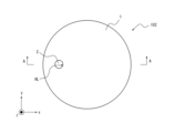
- FIG. FIG. 2 is a top view schematically showing an example of the lid for underground structures shown in FIG. 1.
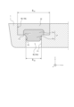
- FIG. 2A is a cross-sectional view schematically showing the underground structure cover shown in FIG. 2A.
- FIG. It is a perspective sectional view showing a part of other examples of the cover for underground structures shown in Drawing 1.
- FIG. 4 is a perspective view showing the inner lid shown in FIG. 3; 4 is a perspective view showing the outer lid shown in FIG. 3.
- FIG. FIG. 4 is a perspective cross-sectional view showing a state in which the small lid of the underground structure lid shown in FIG. 3 is removed.
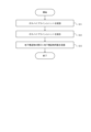
- 2 is a flowchart showing an example of a process for constructing the gas exhaust system shown in FIG. 1.
- FIG. 2 is a flowchart showing an example of the operation of the gas exhaust system shown in FIG. 1.
- FIG. 1 is a schematic diagram of a gas exhaust system according to an
- FIG. 1 is a schematic diagram of a gas exhaust system 100 according to this embodiment.
- the gas exhaust system 100 includes an underground structure 101 and an underground structure lid 102.
- the underground structure 101 is provided underground A and defines an underground space S1.
- the underground structure 101 can be a manhole, a tunnel, a handhole, or the like.
- a part of the gas pipeline 31 is installed in the underground space S1.
- One end of the gas pipeline 31 is connected to the supply port of the gas tank 32 on the supply side, so that the gas supplied from the gas tank 32 on the supply side is supplied to the gas pipeline 31 from the one end. It is provided.
- the other end of the gas pipeline 31 is connected to the intake port of the gas tank 33 on the consumption side, and the gas supplied from the gas tank 32 on the supply side and transported through the gas pipeline 31 is passed through the intake port. It is provided so as to flow into the gas tank 32 on the consumption side through the gas tank 32 on the consumption side.
- the gas pipeline 31 is arranged across the supply port of the gas tank 32 on the supply side, the above-ground space S2, the underground space S1, the pipe line 34 that communicates the underground spaces S1, and the intake port of the gas tank 33 on the consumption side.
- the gas in this embodiment is, for example, hydrogen, but is not limited to hydrogen.
- the gas pipeline 31 is a hydrogen pipeline
- the supply side gas tank 32 is a supply side hydrogen tank
- the consumption side gas tank 32 is a consumption side hydrogen tank.
- the underground structure lid 102 has a main body portion 1 and a small lid 2.
- the main body portion 1 is a member that covers an opening provided in the underground structure 101 that communicates the underground space S1 and the above ground space S2.
- the main body 1 has the shape of a plate surface, and the plate surface is circular. Further, the main body 1 defines a through hole HL passing through the main body 1.
- the through hole HL may have a cylindrical shape.
- the through-hole HL has a first through-hole portion HL1 having a hole diameter (first hole diameter) R h1 and a first through-hole portion HL1 in the through-hole direction. It may also have a second through hole portion HL2 that is adjacent in the z-axis direction in FIG. 3 and has a diameter (second hole diameter) R h2 that is shorter than the hole diameter R h1 .
- first through hole portion HL1 is located on the ground space S2 side
- the second through hole portion HL2 is located on the ground space S2 side. , located on the underground space S1 side.
- Each of the hole diameter R h1 and the hole diameter R h2 can be set to a length such that the underground structure lid 102 has a predetermined strength or more.
- the predetermined strength is a strength that can close off the underground space S1 without being damaged by the pressure expected to be received from the above ground space S2 side.
- main body part 1 may define a gas pipeline through hole that passes through the main body part 1 and passes the gas pipeline 31 from the underground space S1 to the above ground space S2.
- the small lid 2 is disposed in the through-hole HL so as to come into pressure contact with the inner surface of the main body 1 that defines the through-hole HL.
- the small lid 2 has flexibility.
- the small lid 2 may be made of rubber.
- the small lid 2 has an inner lid. 21 and an outer lid 22.
- Each of the inner lid 21 and the outer lid 22 has flexibility.
- the inner lid 21 is disposed in the second through-hole portion HL2 so that at least a portion thereof is in pressure contact with the inner surface F1 of the main body portion 1 that defines the second through-hole portion HL2.
- the inner lid 21 may have a first inner lid part 21a and a second inner lid part 21b.
- the first inner lid part 21a has a diameter (first diameter) R 1a (see FIG. 4) that is shorter than the hole diameter R h1 and longer than the hole diameter R h2 , and as shown in FIG. It is arranged in section HL1.
- the second inner cover part 21b is provided adjacent to the first inner cover part 21a in the penetration direction and integrally with the first inner cover part 21a.
- the second inner lid portion 21b is disposed in the second through-hole portion HL2 so as to be in pressure contact with the inner surface F1 of the main body portion 1 that defines the second through-hole portion HL2.
- the diameter R 1b (see FIG. 4) of the second inner lid portion 21b is larger than the hole diameter R h2 (see FIG. 3) when the second inner lid portion 21b is not inserted into the second through-hole portion HL2.
- the hole diameter Rh can be made equal to the hole diameter Rh2 .
- the first inner lid part 21a is disposed in the first through hole part HL1 with the side opposite to the second inner lid part 21b facing the ground space S2, and
- the inner lid portion 21b is arranged in the second through hole portion HL2.
- a flexible protrusion (first protrusion) P1 may be provided on the side surface of the second inner lid portion 21b in the direction perpendicular to the penetration direction.
- the protrusion P1 is large enough to press against the side surface F1 of the main body 1 that defines the second through hole HL2 when the second inner lid 21b is inserted into the second through hole HL2. It has a size and shape.
- the size and shape of the protrusion P1 are determined depending on the diameter R 1b of the second inner lid part 21b, the flexibility of the material forming the second inner lid part 21b, and the degree to which the second inner lid part 21b is connected to the second inner lid part 21b. It is determined as appropriate depending on the pressure caused by the gas when it comes off from the through hole portion HL2.
- the outer lid 22 covers the first through hole HL1 side of the inner lid 21 and is disposed in the first through hole HL1.
- the outer cover 22 is disposed within the first through-hole portion HL1 so as to come into pressure contact with the inner surface of the main body portion 1 that defines the first through-hole portion HL1.
- the diameter R 2 (see FIG. 5) of the outer lid 22 is larger than the hole diameter R h1 (see FIG. 3) when the outer lid 22 is not inserted into the first through hole HL1, and the outer lid 22 is compressed and When inserted into the through hole portion HL1, the hole diameter R h1 can be made equal to the hole diameter Rh1.
- the outer cover 22 is arranged so that the recess side faces the underground space S1. Thereby, the outer lid 22 covers the first inner lid part 21a in a state arranged in the first through hole part HL1.
- the outer cover 22 since the outer cover 22 has flexibility, it bends when a vehicle or the like passes through the underground structure cover 102 on the ground space S2 side and receives a load. , the load applied to the inner lid 21 can be reduced.
- a flexible protrusion (second protrusion) P2 may be provided on the outer circumferential surface of the outer lid 22 in a direction perpendicular to the penetration direction.
- the outer lid 22 may further be provided with a protrusion P2.
- the protrusion P2 may be provided so as to be in pressure contact with the inner surface of the main body portion 1 that defines the first through-hole portion HL1 without being in pressure contact with the inner surface thereof.
- the shape of the protrusion P2 is arbitrary, and is formed according to the flexibility of the outer cover 22 so that the protrusion P2 and the outer cover 22 can be compressed and arranged in the first through hole HL1. It's fine.
- the protrusion P2 may have a shape having a recessed portion inside.
- the predetermined value is the minimum pressure of the gas in the underground space S1 pressing against the inner lid 21 when the small lid 2 is pushed out to the above ground space S2 side and the underground space S1 and the above ground space S2 are communicated. It is determined depending on the weight, material, shape, etc. of the inner lid 21 and outer lid 22.
- FIG. 7 is a sequence diagram illustrating an example of a method for constructing a gas exhaust system according to this embodiment.
- step S11 and step S12 a supply side, a part of which is disposed in the pipe 34 that communicates the plurality of underground structures 101 and the underground spaces S1 defined by each of the plurality of underground structures 101,
- a gas pipeline 31 is constructed to transport gas from a gas tank 32 on the consumption side to a gas tank 33 on the consumption side.
- each of a plurality of gas pipeline units which are bendable, hollow pipes, is arranged in a plurality of conduits 34 through the underground structure 101.
- the pipe line 34 in which the gas pipeline unit is installed is not provided with a fixed object such as a cable. Note that one end of one gas pipeline unit is attached to the supply port of the gas tank 32 on the supply side, and one end of the other gas pipeline unit is attached to the intake port of the gas tank 33 on the consumption side.
- step S12 the plurality of gas pipeline units arranged in step S11 are coupled to each other. As a result, the gas pipeline 31 composed of a plurality of gas pipeline units is completed.
- step S13 the above-mentioned underground structure lids 102 are respectively disposed in the openings provided in each of the plurality of underground structures 101 that communicate the underground space S1 and the above ground space S2.
- FIG. 8 is a sequence diagram showing an example of the operation of the gas exhaust system 100 according to this embodiment.
- step S21 the gas tank 32 on the supply side supplies gas to the gas pipeline 31.
- step S22 if the gas pressure is less than the predetermined value, the process returns to step S21. In step S22, if the gas pressure is equal to or higher than the predetermined value, the process proceeds to step S23.
- step S23 the small lid 2 is pulled out of the through hole HL defined by the main body 1 by being pressed by the gas.
- step S24 the small lid 2 is removed from the through hole HL, the underground space S1 and the above ground space S2 are communicated, and the gas is discharged.
- the manager of the gas pipeline 31 can enter the underground space S1 and repair the gas pipeline 31. Thereafter, the gas exhaust system 100 can again begin the operations described above.
- the underground structure lid 102 is the main body part 1 disposed in the opening provided in the underground structure 101 that communicates the underground space S1 and the above ground space S2. a main body part 1 defining a through hole HL passing through the main body part 1; A small lid 2 having flexibility is provided.
- the through hole HL is adjacent to the first through hole portion HL1 having the hole diameter R h1 in the penetrating direction, and has the hole diameter R h1.
- the small lid 2 has a second through hole portion HL2 having a hole diameter Rh2 shorter than h1 , and at least a portion of the small lid 2 is pressed against the inner surface of the main body portion 1 defining the second through hole portion HL2. As shown in FIG. It has an outer lid 22. Thereby, the inner lid 21 is pushed out toward the above-ground space S2 by the pressure of the gas leaked into the underground space S1, and the gas can be discharged.
- the outer cover 22 can suppress dust from entering the through hole HL and the underground space S1, and the inner cover can suppress dust from entering the through hole HL and the underground space S1. be able to.
- the inner lid 21 has a diameter R 1a that is shorter than the hole diameter R h1 and longer than the hole diameter R h2
- the inner lid 21 has a diameter R 1a that is shorter than the hole diameter R h1 and longer than the hole diameter R h2.
- the first inner lid part 21a is adjacent to the first inner lid part 21a in the penetration direction, is provided integrally with the first inner lid part 21a, and is pressed into contact with the inner surface defining the second through hole part HL2.
- the second inner lid part 21b is disposed in the second through hole part HL2.
- the flexible protrusion P1 is provided on the side surface of the second inner lid portion 21b in the direction orthogonal to the penetration direction. Therefore, it is possible to more reliably prevent the inner lid 21 from coming off until the pressure from the underground space S1 reaches the pressure due to gas leakage. Therefore, it is possible to more reliably prevent the inner lid 21 from coming off and communicating between the underground space S1 and the above-ground space S2 when gas is not leaking.
- the outer cover 22 is attached to the first through hole portion HL1 so as to be in pressure contact with the inner surface of the main body portion 1 that defines the first through hole portion HL1. It is arranged. Thereby, it is possible to suppress the outer cover 22 from coming off until the pressure from the underground space S1 reaches the pressure due to gas leakage. Therefore, it is possible to prevent the outer cover 22 from coming off and the inner cover 21 from easily coming off when gas is not leaking.
- the flexible protrusion P2 is provided on the side surface of the outer cover 22 in the direction perpendicular to the penetration direction. Therefore, it is possible to more reliably prevent the outer cover 22 from coming off until the pressure from the underground space S1 reaches the pressure due to gas leakage. Therefore, it is possible to more reliably prevent the outer cover 22 from coming off and the inner cover 21 from easily coming off when no gas is leaking.
- a main body part that covers an opening provided in an underground structure that communicates an underground space and an above-ground space, and defines a through hole passing through the main body part;
- a cover for an underground structure comprising: a flexible small cover disposed in the through-hole so as to come into pressure contact with an inner surface of the main body defining the through-hole.
- the through hole includes a first through hole portion having a first hole diameter, and a second through hole portion adjacent to the first through hole portion in the penetration direction and having a second hole diameter shorter than the first hole diameter.
- the small lid is an inner lid disposed in the second through-hole so that at least a portion thereof is in pressure contact with the inner surface defining the second through-hole; an outer cover disposed in the first through-hole portion and covering the first through-hole side of the inner lid;
- the inner lid is a first inner lid portion having a first diameter shorter than the first hole diameter and longer than the second hole diameter and disposed in the first through hole portion; Adjacent to the first inner lid part in the penetration direction, the first inner lid part is provided integrally with the first inner lid part, and is in pressure contact with the inner surface defining the second through hole part.
- the lid for an underground structure according to Supplementary Note 2 which has the following.
- the lid for an underground structure according to Supplementary Note 3 wherein a flexible first protrusion is provided on a side surface of the second inner lid portion in a direction perpendicular to the penetration direction.
- the outer cover may be disposed in the first through-hole portion so as to be in pressure contact with the inner surface defining the first through-hole portion of the main body portion. Lid for underground structures as described in item (1) above.
- the lid for an underground structure according to any one of Supplementary Notes 2 to 5, wherein a flexible second protrusion is provided on a side surface of the outer lid in a direction perpendicular to the penetration direction.
- the lid for underground structures is a main body part that covers an opening provided in the underground structure that communicates an underground space with an above-ground space, and defines a through hole passing through the main body part;
- a gas exhaust system comprising: a flexible small lid disposed in the through hole so as to be in pressure contact with an inner surface of the main body defining the through hole.
Landscapes
- Engineering & Computer Science (AREA)
- Environmental & Geological Engineering (AREA)
- Life Sciences & Earth Sciences (AREA)
- General Life Sciences & Earth Sciences (AREA)
- Mining & Mineral Resources (AREA)
- Paleontology (AREA)
- Civil Engineering (AREA)
- General Engineering & Computer Science (AREA)
- Structural Engineering (AREA)
- Filling Or Discharging Of Gas Storage Vessels (AREA)
Priority Applications (2)
| Application Number | Priority Date | Filing Date | Title |
|---|---|---|---|
| PCT/JP2022/029858 WO2024029010A1 (ja) | 2022-08-03 | 2022-08-03 | 地下構造物用蓋、ガス排出システム、及びガス排出システム構築方法 |
| JP2024538594A JPWO2024029010A1 (https=) | 2022-08-03 | 2022-08-03 |
Applications Claiming Priority (1)
| Application Number | Priority Date | Filing Date | Title |
|---|---|---|---|
| PCT/JP2022/029858 WO2024029010A1 (ja) | 2022-08-03 | 2022-08-03 | 地下構造物用蓋、ガス排出システム、及びガス排出システム構築方法 |
Publications (1)
| Publication Number | Publication Date |
|---|---|
| WO2024029010A1 true WO2024029010A1 (ja) | 2024-02-08 |
Family
ID=89848691
Family Applications (1)
| Application Number | Title | Priority Date | Filing Date |
|---|---|---|---|
| PCT/JP2022/029858 Ceased WO2024029010A1 (ja) | 2022-08-03 | 2022-08-03 | 地下構造物用蓋、ガス排出システム、及びガス排出システム構築方法 |
Country Status (2)
| Country | Link |
|---|---|
| JP (1) | JPWO2024029010A1 (https=) |
| WO (1) | WO2024029010A1 (https=) |
Citations (12)
| Publication number | Priority date | Publication date | Assignee | Title |
|---|---|---|---|---|
| JPS578855U (https=) * | 1980-06-11 | 1982-01-18 | ||
| US4597692A (en) * | 1984-07-12 | 1986-07-01 | Clearwater Technologies, Inc. | Rehabilitated manhole cover |
| JPS6341652U (https=) * | 1986-08-30 | 1988-03-18 | ||
| JPH0233845U (https=) * | 1988-08-29 | 1990-03-02 | ||
| JPH0734475A (ja) * | 1993-07-17 | 1995-02-03 | Kansei Kogyo Kk | 地中管路用蓋の雨水浸入防止構造 |
| GB2331539A (en) * | 1997-11-20 | 1999-05-26 | John Brown | Keyhole plug |
| JPH11152764A (ja) * | 1997-11-19 | 1999-06-08 | Takeda Seisakusho:Kk | マンホール蓋及びその運搬車 |
| EP1111138A2 (en) * | 1999-12-23 | 2001-06-27 | TPL TECNOGHISA S.r.l. | Device for maintaining manhole closures coplanar with the road surface |
| KR100762735B1 (ko) * | 2007-02-12 | 2007-10-02 | 주식회사 정원주철 | 배기밸브가 장착된 맨홀뚜껑 |
| KR100856028B1 (ko) * | 2007-03-07 | 2008-09-02 | (주)앰앤지케스텍 | 맨홀뚜껑의 가스 방출밸브 |
| CN204530771U (zh) * | 2015-03-23 | 2015-08-05 | 长兴宏兴实业有限公司 | 防雨水通信窨井盖 |
| JP2016160606A (ja) * | 2015-02-27 | 2016-09-05 | 日之出水道機器株式会社 | 排気弁装置および排気弁装置を備えた地下構造物用蓋 |
-
2022
- 2022-08-03 JP JP2024538594A patent/JPWO2024029010A1/ja active Pending
- 2022-08-03 WO PCT/JP2022/029858 patent/WO2024029010A1/ja not_active Ceased
Patent Citations (12)
| Publication number | Priority date | Publication date | Assignee | Title |
|---|---|---|---|---|
| JPS578855U (https=) * | 1980-06-11 | 1982-01-18 | ||
| US4597692A (en) * | 1984-07-12 | 1986-07-01 | Clearwater Technologies, Inc. | Rehabilitated manhole cover |
| JPS6341652U (https=) * | 1986-08-30 | 1988-03-18 | ||
| JPH0233845U (https=) * | 1988-08-29 | 1990-03-02 | ||
| JPH0734475A (ja) * | 1993-07-17 | 1995-02-03 | Kansei Kogyo Kk | 地中管路用蓋の雨水浸入防止構造 |
| JPH11152764A (ja) * | 1997-11-19 | 1999-06-08 | Takeda Seisakusho:Kk | マンホール蓋及びその運搬車 |
| GB2331539A (en) * | 1997-11-20 | 1999-05-26 | John Brown | Keyhole plug |
| EP1111138A2 (en) * | 1999-12-23 | 2001-06-27 | TPL TECNOGHISA S.r.l. | Device for maintaining manhole closures coplanar with the road surface |
| KR100762735B1 (ko) * | 2007-02-12 | 2007-10-02 | 주식회사 정원주철 | 배기밸브가 장착된 맨홀뚜껑 |
| KR100856028B1 (ko) * | 2007-03-07 | 2008-09-02 | (주)앰앤지케스텍 | 맨홀뚜껑의 가스 방출밸브 |
| JP2016160606A (ja) * | 2015-02-27 | 2016-09-05 | 日之出水道機器株式会社 | 排気弁装置および排気弁装置を備えた地下構造物用蓋 |
| CN204530771U (zh) * | 2015-03-23 | 2015-08-05 | 长兴宏兴实业有限公司 | 防雨水通信窨井盖 |
Also Published As
| Publication number | Publication date |
|---|---|
| JPWO2024029010A1 (https=) | 2024-02-08 |
Similar Documents
| Publication | Publication Date | Title |
|---|---|---|
| JP5993071B2 (ja) | 開口に密封システムを提供するアセンブリ | |
| US2817230A (en) | Leak testing device | |
| US7258141B2 (en) | Pipe liner apparatus and method | |
| US6959734B2 (en) | Flow-through inflatable plug | |
| KR20140015935A (ko) | 배관 연결부 누설검사장치 | |
| US9822905B2 (en) | Process and device for laying a pipe-in-pipe | |
| US7118137B2 (en) | Testable pipe joint | |
| WO2024029010A1 (ja) | 地下構造物用蓋、ガス排出システム、及びガス排出システム構築方法 | |
| JPH0513453B2 (https=) | ||
| US20070284879A1 (en) | Coupling, particularly pipe coupling for high-pressure pipes or hoses | |
| KR20070061430A (ko) | 심온 냉동 매체 수송용 라인 파이프 | |
| JP7336496B2 (ja) | 水密テスト機および検査方法 | |
| KR20120085398A (ko) | 비굴착식 파형강관 보수 방법 및 이에 사용되는 팩커 | |
| US20160097480A1 (en) | Upstream pipe plug | |
| KR20090104989A (ko) | 상하수도 관로 비굴착 장 반전장치 및 이를 이용한상하수도 관로 보수공법 | |
| KR102386986B1 (ko) | 유연성이 있는 플렉시블 타입 관로 부분 보수장치를 이용한 관로의 부분보수공법 | |
| JP2006300865A (ja) | 防水材の密性検査方法 | |
| JP7727240B2 (ja) | ベントシステム及びベント方法 | |
| JPH0251699A (ja) | 海底油田開発における炭化水素の輸送のための可撓導管 | |
| KR101212712B1 (ko) | 원통 터널식 밸브실 | |
| TWI920716B (zh) | 配線或配管的固定構造 | |
| KR20200103358A (ko) | 반도체 제조설비용 공정가스 배기관 | |
| JP3125502B2 (ja) | ゴムの継ぎ目の気密試験方法 | |
| WO2024029009A1 (ja) | 配管挟持器具及び配管挟持方法 | |
| GB2194302A (en) | Resilient pipe coupling |
Legal Events
| Date | Code | Title | Description |
|---|---|---|---|
| 121 | Ep: the epo has been informed by wipo that ep was designated in this application |
Ref document number: 22953999 Country of ref document: EP Kind code of ref document: A1 |
|
| WWE | Wipo information: entry into national phase |
Ref document number: 2024538594 Country of ref document: JP |
|
| NENP | Non-entry into the national phase |
Ref country code: DE |
|
| 122 | Ep: pct application non-entry in european phase |
Ref document number: 22953999 Country of ref document: EP Kind code of ref document: A1 |