WO2024028622A1 - 二次電池 - Google Patents
二次電池 Download PDFInfo
- Publication number
- WO2024028622A1 WO2024028622A1 PCT/IB2022/000434 IB2022000434W WO2024028622A1 WO 2024028622 A1 WO2024028622 A1 WO 2024028622A1 IB 2022000434 W IB2022000434 W IB 2022000434W WO 2024028622 A1 WO2024028622 A1 WO 2024028622A1
- Authority
- WO
- WIPO (PCT)
- Prior art keywords
- solid electrolyte
- electrolyte layer
- active material
- electrode active
- layer
- Prior art date
- Legal status (The legal status is an assumption and is not a legal conclusion. Google has not performed a legal analysis and makes no representation as to the accuracy of the status listed.)
- Ceased
Links
Images


Classifications
-
- H—ELECTRICITY
- H01—ELECTRIC ELEMENTS
- H01M—PROCESSES OR MEANS, e.g. BATTERIES, FOR THE DIRECT CONVERSION OF CHEMICAL ENERGY INTO ELECTRICAL ENERGY
- H01M10/00—Secondary cells; Manufacture thereof
- H01M10/05—Accumulators with non-aqueous electrolyte
- H01M10/052—Li-accumulators
-
- H—ELECTRICITY
- H01—ELECTRIC ELEMENTS
- H01M—PROCESSES OR MEANS, e.g. BATTERIES, FOR THE DIRECT CONVERSION OF CHEMICAL ENERGY INTO ELECTRICAL ENERGY
- H01M10/00—Secondary cells; Manufacture thereof
- H01M10/05—Accumulators with non-aqueous electrolyte
- H01M10/056—Accumulators with non-aqueous electrolyte characterised by the materials used as electrolytes, e.g. mixed inorganic/organic electrolytes
- H01M10/0561—Accumulators with non-aqueous electrolyte characterised by the materials used as electrolytes, e.g. mixed inorganic/organic electrolytes the electrolyte being constituted of inorganic materials only
- H01M10/0562—Solid materials
-
- H—ELECTRICITY
- H01—ELECTRIC ELEMENTS
- H01M—PROCESSES OR MEANS, e.g. BATTERIES, FOR THE DIRECT CONVERSION OF CHEMICAL ENERGY INTO ELECTRICAL ENERGY
- H01M10/00—Secondary cells; Manufacture thereof
- H01M10/05—Accumulators with non-aqueous electrolyte
- H01M10/058—Construction or manufacture
- H01M10/0585—Construction or manufacture of accumulators having only flat construction elements, i.e. flat positive electrodes, flat negative electrodes and flat separators
Definitions
- the present invention relates to a secondary battery using a solid electrolyte.
- Secondary batteries for motor drives are required to have extremely high output characteristics and high energy density compared to consumer secondary batteries used in mobile phones, notebook computers, etc. Therefore, lithium secondary batteries, which have the highest theoretical energy of all practical batteries, are attracting attention and are currently being rapidly developed.
- lithium secondary batteries that are currently in widespread use use a flammable organic electrolyte as the electrolyte.
- Such liquid-based lithium secondary batteries require more stringent safety measures against leakage, short circuits, overcharging, etc. than other batteries.
- a solid electrolyte is a material mainly composed of an ion conductor capable of ion conduction in a solid state. Therefore, in principle, all-solid-state lithium secondary batteries do not suffer from various problems caused by flammable organic electrolytes, unlike conventional liquid-based lithium secondary batteries. Furthermore, in general, the use of a high potential/large capacity positive electrode material and a large capacity negative electrode material can significantly improve the output density and energy density of the battery.
- an object of the present invention is to provide a means for improving the charging capacity during rapid charging in a secondary battery equipped with a solid electrolyte layer.
- the present inventors conducted extensive studies to solve the above problems. As a result, in a secondary battery using a solid electrolyte, two solid electrolyte layers are provided, and the thickness of the first solid electrolyte layer located on the positive electrode side is greater than the thickness of the second solid electrolyte layer located on the negative electrode side. It has been discovered that the above problem can be solved by reducing the binder concentration in the first solid electrolyte layer and making the binder concentration in the first solid electrolyte layer higher than that in the second solid electrolyte layer within a specific range, and has developed the present invention. I ended up completing it.
- one form of the present invention includes a positive electrode in which a positive electrode active material layer is disposed on the surface of a positive electrode current collector, a negative electrode in which a negative electrode active material layer is disposed on the surface of the negative electrode current collector, a solid electrolyte, and a binder.
- the present invention relates to a secondary battery including a first solid electrolyte layer and a second solid electrolyte layer, each of which contains a first solid electrolyte layer and a second solid electrolyte layer.
- the positive electrode and the negative electrode are arranged to face each other such that the positive electrode active material layer and the negative electrode active material layer sandwich the first solid electrolyte layer and the second solid electrolyte layer, and the first solid electrolyte layer
- the second solid electrolyte layer is disposed on the positive electrode active material layer side and the second solid electrolyte layer is disposed on the negative electrode active material layer side, the thickness of the first solid electrolyte layer is smaller than the thickness of the second solid electrolyte layer, and the first solid electrolyte layer is disposed on the positive electrode active material layer side.
- the ratio (A/B) of the concentration (A) [mass%] of the binder to the total solid content of the electrolyte layer and the concentration (B) [mass%] of the binder to the total solid content of the second solid electrolyte layer is It is characterized in that 1 ⁇ A/B ⁇ 4.5.
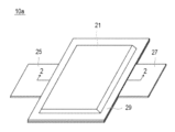
- FIG. 1 is a perspective view showing the appearance of a flat stacked secondary battery that is an embodiment of the present invention.
- FIG. 2 is a sectional view taken along line 2-2 shown in FIG.
- FIG. 3 is a schematic diagram showing an enlarged cross section of a single cell layer constituting a power generation element of the stacked secondary battery shown in FIGS. 1 and 2.
- FIG. 1 is a perspective view showing the appearance of a flat stacked secondary battery that is an embodiment of the present invention.
- FIG. 2 is a sectional view taken along line 2-2 shown in FIG.
- FIG. 3 is a schematic diagram showing an enlarged cross section of a single cell layer constituting a power generation element of the stacked secondary battery shown in FIGS. 1 and 2.
- FIG. 1 is a perspective view showing the appearance of a flat stacked secondary battery that is an embodiment of the present invention.
- FIG. 2 is a sectional view taken along line 2-2 shown in FIG.
- FIG. 3 is a schematic diagram showing an enlarged cross section of a single
- One form of the present invention includes a positive electrode in which a positive electrode active material layer is disposed on the surface of a positive electrode current collector, a negative electrode in which a negative electrode active material layer is disposed on the surface of the negative electrode current collector, a solid electrolyte, and a binder.
- first solid electrolyte layer and a second solid electrolyte layer each of which contains a first solid electrolyte layer and a second solid electrolyte layer;
- the first solid electrolyte layer is placed on the positive electrode active material layer side
- the second solid electrolyte layer is placed on the negative electrode active material layer side
- the thickness of the first solid electrolyte layer is is smaller than the thickness of the second solid electrolyte layer, and the concentration (A) [mass%] of the binder with respect to the total solid content of the first solid electrolyte layer and the concentration of the binder with respect to the total solid content of the second solid electrolyte layer
- B A secondary battery in which the ratio (A/B) of [mass%] is 1 ⁇ A/B ⁇ 4.5. According to this embodiment, the charging capacity during rapid charging can be improved in a secondary battery including a solid electrolyte layer.
- All-solid-state lithium secondary batteries have the advantage that, unlike conventional liquid-based lithium secondary batteries, problems caused by flammable organic electrolytes do not occur in principle. There is also the advantage that the output density and energy density of the battery can be significantly improved by using a negative electrode material with a large capacity.
- FIG. 1 is a perspective view showing the appearance of a flat stacked all-solid-state lithium secondary battery that is an embodiment of the present invention.
- FIG. 2 is a sectional view taken along line 2-2 shown in FIG.
- a flat stacked non-bipolar all-solid-state lithium secondary battery shown in FIGS. 1 and 2 will be used as an example for detailed explanation. do.
- both non-bipolar (internal parallel connection type) batteries and bipolar (internal series connection type) batteries is applicable.
- the stacked secondary battery 10a has a flat rectangular shape, and a negative current collector plate 25 and a positive current collector plate 27 for extracting power are pulled out from both sides of the battery. It is.
- the power generation element 21 is surrounded by the battery exterior material (laminate film 29) of the stacked secondary battery 10a, and the periphery thereof is heat-sealed. It is sealed in a state where it is pulled out to the outside.
- the power generation element 21 has a structure in which a positive electrode, a solid electrolyte layer 17, and a negative electrode are stacked.
- the positive electrode has a structure in which positive electrode active material layers 15 containing a positive electrode active material are disposed on both sides of a positive electrode current collector 11''.
- the negative electrode has a structure in which positive electrode active material layers 15 containing a positive electrode active material are arranged on both sides of a negative electrode current collector 11'. It has a structure in which an active material layer 13 is arranged.
- the solid electrolyte layer 17 is composed of two layers, a first solid electrolyte layer and a second solid electrolyte layer, as described later.
- a negative current collector plate 25 and a positive current collector plate 27 that are electrically connected to each electrode are attached to the negative electrode current collector 11' and the positive electrode current collector 11'', respectively, and are attached to the ends of the laminate film 29. It has a structure in which it is led out to the outside of the laminate film 29 in a sandwiched manner.
- the negative electrode current collector plate 25 and the positive electrode current collector plate 27 each have a negative electrode terminal lead and a positive electrode terminal lead (not shown) as necessary. ) may be attached to the negative electrode current collector 11' and the positive electrode current collector 11'' of each electrode by ultrasonic welding, resistance welding, or the like.
- FIG. 3 is a schematic diagram showing an enlarged cross section of the unit cell layer 19 that constitutes the power generation element 21 of the stacked secondary battery 10a shown in FIGS. 1 and 2.
- the positive electrode active material layer 15 and the negative electrode active material layer 13 are arranged so as to sandwich the first solid electrolyte layer 17a and the second solid electrolyte layer 17b,
- the first solid electrolyte layer 17a is arranged on the positive electrode active material layer 15 side
- the second solid electrolyte layer 17b is arranged on the negative electrode active material layer 13 side.
- the unit cell layer 19 includes the positive electrode current collector 11'', the positive electrode active material layer 15, the first solid electrolyte layer 17a, the second solid electrolyte layer 17b, the negative electrode active material layer 13, and the negative electrode current collector. and the body 11' are laminated in this order.
- the thickness of the first solid electrolyte layer is smaller than the thickness of the second solid electrolyte layer
- the binder content is smaller than the total solid content of the first solid electrolyte layer.
- the ratio (A/B) of the concentration (A) [mass %] and the binder concentration (B) [mass %] with respect to the total solid content of the second solid electrolyte layer is 1 ⁇ A/B ⁇ 4.5. It is.
- the secondary battery according to the present invention can improve the charging capacity during rapid charging in a secondary battery equipped with a solid electrolyte layer. Although the details of the reason for this effect are unknown, the following mechanism is considered.
- the concentration of the binder contained in the first solid electrolyte layer is higher than the concentration of the binder contained in the second solid electrolyte layer. Therefore, a large amount of binder exists on the surface layer of the first solid electrolyte layer. Since these binders bind to the positive electrode active material, solid electrolyte, conductive aid, binder, etc. present on the surface layer of the positive electrode active material layer, the adhesive force between the first solid electrolyte layer and the positive electrode active material layer increases, It is thought that peeling of both layers is suppressed. Furthermore, since the first solid electrolyte layer is thin, a decrease in ionic conductivity is suppressed.
- the second solid electrolyte layer provided together with the first solid electrolyte layer has a large layer thickness, it is possible to prevent short circuits in the secondary battery due to generation of dendrites and cracks in the solid electrolyte layer. Furthermore, since the second solid electrolyte layer has a low binder concentration, it is possible to maintain high ionic conductivity even if the layer is thick. As described above, in the secondary battery according to the present invention, by increasing the adhesion between the positive electrode active material layer and the solid electrolyte layer, separation of both layers is prevented, short circuits due to dendrite formation, etc. are prevented, and the solid electrolyte layer Since the ionic conductivity of the battery can also be maintained, it is thought that the charging capacity during rapid charging can be improved.
- a stacked secondary battery 10a includes a power generation element 21 sealed in a laminate film 29 shown in FIG. 1, and a power generation element 21 sealed in the laminate film 29 sandwiched between two plate-like members. , it is preferable that they are further fastened using a fastening member.
- the plate member and the fastening member function as a pressure member that presses (restricts) the power generation element 21 in the stacking direction thereof.
- the plate-like member include metal plates and resin plates.
- fastening members include bolts and nuts.
- the pressurizing member is not particularly limited as long as it is a member that can pressurize the power generation elements 21 in the stacking direction thereof.
- a combination of a plate made of a rigid material, such as a plate-shaped member, and the above-mentioned fastening member is used as the pressure member.
- the fastening member not only bolts and nuts but also a tension plate or the like that fixes the end of a plate-like member so as to restrain the power generation element 21 in the stacking direction thereof may be used.
- the lower limit of the load applied to the power generation element 21 is, for example, 0.1 MPa or more, preferably 0.5 MPa or more, more preferably 1 MPa or more, and Preferably it is 3 MPa or more.
- the upper limit of the confining pressure in the stacking direction of the power generation elements is, for example, 100 MPa or less, preferably 70 MPa or less, more preferably 40 MPa or less, and still more preferably 10 MPa or less.
- the current collectors (negative electrode current collector 11' and positive electrode current collector 11'') have a function of mediating the movement of electrons from the electrode active material layer.
- the material that constitutes the current collector There are no particular restrictions on the material that constitutes the current collector.
- the constituent material of the electric body for example, metal or conductive resin can be used.
- metals include aluminum, nickel, iron, stainless steel, titanium, copper, and the like.
- a cladding material of nickel and aluminum, a cladding material of copper and aluminum, etc. may be used.
- it may be a foil whose metal surface is coated with aluminum.
- aluminum, stainless steel, copper, and nickel are preferable from the viewpoint of electron conductivity, battery operating potential, adhesion of active material, and the like.
- examples of the latter resin having conductivity include resins in which a conductive filler is added to a conductive polymer material or a non-conductive polymer material as necessary.
- the current collector may have a single-layer structure made of a single material, or may have a laminated structure in which layers made of these materials are appropriately combined. From the viewpoint of reducing the weight of the current collector, it is preferable to include at least a conductive resin layer made of a resin having conductivity.
- the negative electrode active material layer contains a negative electrode active material.
- the type of negative electrode active material is not particularly limited, and examples thereof include carbon materials, metal oxides, and metal active materials.
- a metal containing lithium may be used as the negative electrode active material.
- Such a negative electrode active material is not particularly limited as long as it is an active material containing lithium, and examples thereof include metal lithium and lithium-containing alloys. Examples of lithium-containing alloys include alloys of Li and at least one of In, Al, Si, Sn, Mg, Au, Ag, and Zn.
- the negative electrode active material preferably contains metallic lithium or a lithium-containing alloy, a silicon-based negative electrode active material, or a tin-based negative electrode active material, and particularly preferably contains metallic lithium or a lithium-containing alloy.
- the secondary battery according to this embodiment is a so-called lithium deposition type secondary battery in which metallic lithium as the negative electrode active material is deposited on the negative electrode current collector during the charging process. It can be something. Therefore, in such a configuration, the thickness of the negative electrode active material layer increases as the charging process progresses, and the thickness of the negative electrode active material layer decreases as the discharging process progresses.
- the negative electrode active material layer does not need to be present at the time of complete discharge, in some cases, a negative electrode active material layer made of a certain amount of metallic lithium may be provided at the time of complete discharge.
- the content of the negative electrode active material in the negative electrode active material layer is not particularly limited, but for example, it is preferably within the range of 40 to 100% by mass, and preferably within the range of 50 to 90% by mass. More preferred.
- the negative electrode active material layer may further include a solid electrolyte if necessary.
- a solid electrolyte By including the solid electrolyte in the negative electrode active material layer, the ionic conductivity of the negative electrode active material layer can be improved.
- the solid electrolyte include sulfide solid electrolytes and oxide solid electrolytes.
- the solid electrolyte refers to a material mainly composed of an ion conductor capable of ion conduction in a solid, and in particular, the lithium ion conductivity at room temperature (25 ° C.) is 1 ⁇ 10 -5 It refers to a material whose lithium ion conductivity is S/cm or more, and preferably has a lithium ion conductivity of 1 ⁇ 10 ⁇ 4 S/cm or more.
- the value of ionic conductivity can be measured by an AC impedance method.
- the solid electrolyte is preferably a sulfide solid electrolyte containing an S element, more preferably containing a Li element, an M element, and an S element, where the M element is P,
- the sulfide solid electrolyte may have a Li 3 PS 4 skeleton, a Li 4 P 2 S 7 skeleton, or a Li 4 P 2 S 6 skeleton.
- Examples of the sulfide solid electrolyte having a Li3PS4 skeleton include LiI - Li3PS4 , LiI- LiBr - Li3PS4 , and Li3PS4 .
- examples of the sulfide solid electrolyte having a Li 4 P 2 S 7 skeleton include a Li-P-S solid electrolyte called LPS.
- LGPS represented by Li (4-x) Ge (1-x) P x S 4 (x satisfies 0 ⁇ x ⁇ 1) or the like may be used. More specifically, for example, LPS (Li 2 S-P 2 S 5 ), Li 7 P 3 S 11 , Li 3.2 P 0.96 S, Li 3.25 Ge 0.25 P 0.75 S 4 , Li 10 GeP 2 S 12 , or Li 6 PS 5 X (where X is Cl, Br or I). Note that the description "Li 2 S-P 2 S 5 " means a sulfide solid electrolyte using a raw material composition containing Li 2 S and P 2 S 5 , and the same applies to other descriptions.
- the sulfide solid electrolyte is preferably LPS (Li 2 S-P 2 S 5 ), Li 6 PS 5 X (argyrodite solid electrolyte, where X is Cl , Br or I), Li 7 P 3 S 11 , Li 3.2 P 0.96 S and Li 3 PS 4 .
- the shape of the solid electrolyte examples include particle shapes such as true spheres and ellipsoids, thin film shapes, and the like.
- the average particle diameter (D50) is not particularly limited, but is preferably 40 ⁇ m or less, more preferably 20 ⁇ m or less, and even more preferably 10 ⁇ m or less.
- the average particle diameter (D50) is preferably 0.01 ⁇ m or more, more preferably 0.1 ⁇ m or more.
- the content of the solid electrolyte in the negative electrode active material layer is, for example, preferably in the range of 1 to 60% by mass, more preferably in the range of 10 to 50% by mass.
- the negative electrode active material layer may further contain at least one of a binder and a conductive aid.
- the thickness of the negative electrode active material layer varies depending on the configuration of the intended secondary battery, but is preferably in the range of 0.1 to 1000 ⁇ m, more preferably 40 to 100 ⁇ m, for example.
- the solid electrolyte layer includes a first solid electrolyte layer and a second solid electrolyte layer, each containing a solid electrolyte and a binder.
- the first solid electrolyte layer is arranged on the positive electrode active material layer side
- the second solid electrolyte layer is arranged on the negative electrode active material layer side
- the thickness of the first solid electrolyte layer is the same as that of the second solid electrolyte layer.
- the concentration of the binder (A) [mass %] relative to the total solid content of the first solid electrolyte layer and the concentration (B) [mass %] of the binder relative to the total solid content of the second solid electrolyte layer are smaller than the thickness of the electrolyte layer. %] and the ratio (A/B) is 1 ⁇ A/B ⁇ 4.5.
- the solid electrolytes contained in the first solid electrolyte layer and the second solid electrolyte layer are not particularly limited, and the solid electrolytes and preferred forms thereof exemplified in the section of the negative electrode active material layer may be similarly employed.
- the solid electrolyte contained in the solid electrolyte layer is preferably a sulfide solid electrolyte from the viewpoint of high ionic conductivity, and is preferably an argyrodite solid electrolyte (Li 6 PS 5 Cl, Br or I)) is more preferred.
- a solid electrolyte other than the solid electrolytes exemplified in the section of the negative electrode active material layer may be used in combination.
- first solid electrolyte layer and the second solid electrolyte layer may contain the same form of solid electrolyte, or may contain different forms of solid electrolyte. According to one preferred form, the first solid electrolyte layer and the second solid electrolyte layer contain the same form of solid electrolyte.
- each solid electrolyte in the first solid electrolyte layer and the second solid electrolyte layer is preferably in the range of 10 to 100% by mass, for example, 50 to 100% by mass, based on the total mass of the solid electrolyte layer. It is more preferably within the range of 90 to 100% by mass, and even more preferably within the range of 90 to 100% by mass.
- the contents of the solid electrolyte in the first solid electrolyte layer and the second solid electrolyte layer may be the same or different.
- the binder contained in each of the first solid electrolyte layer and the second solid electrolyte layer is not particularly limited, it is a substance that is stable in the potential range of charging and discharging operation, and also has a property that is compatible with the strength of the solid electrolyte layer and the positive electrode active material layer. From the viewpoint of adhesiveness, it is preferable to select from the group consisting of polyvinylidene fluoride (PVDF), styrene-butadiene rubber (SBR), acrylic resin, and polytetrafluoroethylene (PTFE); More preferably, it is selected from the group consisting of styrene-butadiene rubber (SBR). Note that the binders contained in the first solid electrolyte layer and the second solid electrolyte layer may be the same or different.
- PVDF polyvinylidene fluoride
- SBR styrene-butadiene rubber
- PTFE polytetrafluoroethylene
- SBR styren
- the solid electrolyte and binder contained in the first solid electrolyte layer and the second solid electrolyte layer may be the same or different.
- the solid electrolyte contained in the first solid electrolyte layer and the solid electrolyte contained in the second solid electrolyte layer are the same, and the solid electrolyte contained in the first solid electrolyte layer is the same.
- the binder contained in the second solid electrolyte layer and the binder contained in the second solid electrolyte layer are the same. Thereby, the charging capacity when rapidly charging the secondary battery can be improved more effectively.
- the concentration (A) of the binder contained in the first solid electrolyte layer is preferably greater than 3% by mass and less than 15% by mass, and more than 4% by mass and 10% by mass, based on the total mass of the first solid electrolyte layer. It is more preferably the following, and even more preferably 5% by mass or more and 8% by mass or less.
- the binder concentration (A) of the first solid electrolyte layer is within the above range, the ionic conductivity of the solid electrolyte layer can be sufficiently maintained while sufficiently improving the adhesive force with the positive electrode active material layer.
- the concentration (B) of the binder contained in the second solid electrolyte layer is preferably 1% by mass or more and 10% by mass or less, and 2% by mass or more and 6% by mass with respect to the total mass of the second solid electrolyte layer. % or less, and even more preferably 2.5% by mass or more and 4% by mass or less.
- the binder concentration (B) of the second solid electrolyte layer is within the above range, it is possible to maintain sufficient ionic conductivity while maintaining sufficient strength of the solid electrolyte layer.
- the ratio ((A)/(B)) between the concentration (A) of the binder contained in the first solid electrolyte layer and the concentration (B) of the binder contained in the second solid electrolyte layer is 1 ⁇ A/ B ⁇ 4.5, preferably 1.2 ⁇ A/B ⁇ 4.0, more preferably 1.5 ⁇ A/B ⁇ 3.5, and 1.8 ⁇ A/ It is more preferable that B ⁇ 3.0.
- concentration ratio of the binder is within the above range, the charging capacity during rapid charging can be more fully improved.
- the thickness (a) of the first solid electrolyte layer is not particularly limited as long as it is smaller than the thickness of the second solid electrolyte layer and does not impair the performance of the intended secondary battery.
- the thickness (a) of the first solid electrolyte layer is preferably 0.1 ⁇ m or more and 5 ⁇ m or less, more preferably 0.5 ⁇ m or more and 3 ⁇ m or less, and still more preferably 1 ⁇ m or more and 2 ⁇ m or less.
- the thickness (b) of the second solid electrolyte layer is also not particularly limited as long as it is larger than the thickness of the first solid electrolyte layer and does not impair the performance of the intended secondary battery.
- the thickness (b) of the second solid electrolyte layer is preferably 3 ⁇ m or more and 50 ⁇ m or less, more preferably 5 ⁇ m or more and 30 ⁇ m or less.
- the ratio (b/a) of the thickness (b) of the second solid electrolyte layer to the thickness (a) of the first solid electrolyte layer is preferably 1 ⁇ b/a ⁇ 50, and 5 ⁇ It is more preferable that b/a ⁇ 40, and even more preferably that 15 ⁇ b/a ⁇ 35. When the thickness ratio is within the above range, the charging capacity when rapidly charging the secondary battery can be more fully improved.
- the positive electrode active material layer is a layer containing a positive electrode active material.
- the type of positive electrode active material is not particularly limited, but may include layered rock salt type active materials such as LiCoO 2 , LiMnO 2 , LiNiO 2 , LiVO 2 , Li(Ni-Mn-Co)O 2 , LiMn 2 O 4 , LiNi 0
- Examples include spinel-type active materials such as .5 Mn 1.5 O 4 , olivine-type active materials such as LiFePO 4 and LiMnPO 4 , and Si-containing active materials such as Li 2 FeSiO 4 and Li 2 MnSiO 4 .
- oxide active materials other than those mentioned above include Li 4 Ti 5 O 12 .
- the positive electrode active material layer preferably contains a positive electrode active material that contracts during charging, and particularly, the positive electrode active material preferably contains a composite oxide containing a lithium element and a nickel element, which further enhances the effects of the present invention. It can be demonstrated. Generally, when the positive electrode active material shrinks, the solid electrolyte layer peels off from the positive electrode active material layer, but in the secondary battery of the present invention, the first solid electrolyte layer firmly adheres to the positive electrode active material layer, so that the solid electrolyte layer peels off. can be prevented.
- a positive electrode active material made of a composite oxide containing a lithium element and a nickel element is characterized by particularly large shrinkage during charging, but even when such a positive electrode active material is used, the In the next battery, it becomes possible to suppress separation between the positive electrode active material layer and the solid electrolyte layer.
- NMC composite oxide Li(Ni-Mn-Co)O 2 and those in which some of these transition metals are replaced with other elements (hereinafter also simply referred to as "NMC composite oxide”) are used as the positive electrode active material.
- NMC composite oxide has a layered crystal structure in which lithium atomic layers and transition metal (Mn, Ni, and Co are arranged in an orderly manner) atomic layers are stacked alternately through oxygen atomic layers, and each atom of transition metal M It contains one Li atom, and the amount of Li that can be taken out is twice that of spinel-based lithium manganese oxide, that is, the supply capacity is doubled, and it can have a high capacity.
- the NMC composite oxide also includes a composite oxide in which a part of the transition metal element is replaced with another metal element.
- Other elements in that case include Ti, Zr, Nb, W, P, Al, Mg, V, Ca, Sr, Cr, Fe, B, Ga, In, Si, Mo, Y, Sn, V, Cu. , Ag, Zn, etc., and preferably Ti, Zr, Nb, W, P, Al, Mg, V, Ca, Sr, and Cr.
- M is Ti, Zr, Nb, W, P , Al, Mg, V, Ca, Sr, and Cr) is used as the positive electrode active material.
- a represents the atomic ratio of Li
- b represents the atomic ratio of Ni
- c represents the atomic ratio of Mn
- d represents the atomic ratio of Co
- x represents the atomic ratio of M. represents.
- a sulfur-based positive electrode active material is used.
- the sulfur-based positive electrode active material include particles or thin films of organic sulfur compounds or inorganic sulfur compounds, which can release lithium ions during charging and store lithium ions during discharge by utilizing the redox reaction of sulfur. Any substance that can be used is fine.
- positive electrode active materials may be used together. Note that, of course, positive electrode active materials other than those mentioned above may be used.
- the shape of the positive electrode active material examples include particulate (spherical, fibrous), thin film, and the like.
- its average particle size (D 50 ) is, for example, preferably within the range of 1 nm to 100 ⁇ m, more preferably within the range of 10 nm to 50 ⁇ m, and even more preferably 100 nm. It is within the range of ⁇ 20 ⁇ m, particularly preferably within the range of 1 ⁇ 20 ⁇ m. Note that in this specification, the value of the average particle diameter (D 50 ) can be measured by a laser diffraction scattering method.
- the content of the positive electrode active material in the positive electrode active material layer is not particularly limited, but preferably exceeds 50% by mass, based on 100% by mass of the total solid content contained in the positive electrode active material layer. % to 95% by mass or less, and even more preferably 60% to 90% by mass.
- the positive electrode active material layer may include a solid electrolyte in addition to the positive electrode active material.
- the type of solid electrolyte contained in the positive electrode active material layer is not particularly limited, but preferably includes a sulfide solid electrolyte.
- the specific form and preferred form of the solid electrolyte such as the sulfide solid electrolyte those explained in the section of the negative electrode (negative electrode active material layer) mentioned above can be similarly adopted.
- the content of the solid electrolyte in the positive electrode active material layer is preferably 1% by mass or more and 70% by mass or less, more preferably 5% by mass or more and 50% by mass or less, based on 100% by mass of the total solid content contained in the positive electrode active material layer.
- the content is not more than 10% by mass and not more than 30% by mass. If the content of the solid electrolyte in the positive electrode active material layer is within the above range, it is possible to achieve both ionic conductivity and energy density of the positive electrode active material layer.
- the positive electrode active material layer may further contain at least one of a binder and a conductive aid.
- the thickness of the positive electrode active material layer varies depending on the configuration of the target secondary battery, and also varies depending on the configuration of the target lithium secondary battery, but for example, it may be within the range of 0.1 to 1000 ⁇ m. The thickness is preferably 40 to 100 ⁇ m.
- the secondary battery according to one embodiment of the present invention may have an intermediate layer containing a carbon material between the negative electrode active material layer and the second solid electrolyte layer.
- Carbon materials include, but are not limited to, carbon black (specifically, acetylene black, Ketjen black (registered trademark), furnace black, channel black, thermal lamp black, etc.), carbon nanotubes (CNT), graphite, and hard carbon. etc. Among them, carbon black is preferable, and at least one selected from the group consisting of acetylene black, Ketjen black (registered trademark), furnace black, channel black, and thermal lamp black is more preferable.
- the content of carbon material in the intermediate layer is not particularly limited, but is preferably in the range of 50 to 100% by mass, more preferably in the range of 60 to 100% by mass, and 70 to 100% by mass. More preferably, it is within the range.
- the intermediate layer may contain nanoparticles containing one or more elements selected from the group consisting of gold, platinum, palladium, silicon, silver, aluminum, bismuth, tin, and zinc. May include.
- the thickness of the intermediate layer is not particularly limited, but is preferably within the range of 1 to 50 ⁇ m, more preferably within the range of 5 to 40 ⁇ m, even more preferably within the range of 10 to 30 ⁇ m, The most preferable range is 5 to 15 ⁇ m.
- the thickness of the intermediate layer is 1 ⁇ m or more, short circuits due to dendrite formation can be further suppressed.
- the thickness of the carbon-containing layer is 50 ⁇ m or less, reduction in energy density can be suppressed.
- the material constituting the current collector plate is not particularly limited, and known highly conductive materials conventionally used as current collector plates for secondary batteries may be used.
- As the constituent material of the current collector plate for example, metal materials such as aluminum, copper, titanium, nickel, stainless steel (SUS), and alloys thereof are preferable. From the viewpoints of light weight, corrosion resistance, and high conductivity, aluminum and copper are more preferred, and aluminum is particularly preferred.
- the positive electrode current collector plate 27 and the negative electrode current collector plate 25 may use the same material or different materials.
- the current collector and the current collecting plate may be electrically connected via a positive electrode lead or a negative electrode lead.
- materials used in known lithium secondary batteries can be similarly adopted.
- the parts taken out from the exterior are covered with heat-resistant insulating heat-shrinkable material to prevent them from contacting peripheral equipment or wiring and causing electrical leakage, which may affect products (e.g., automobile parts, especially electronic equipment, etc.).
- it is covered with a tube or the like.
- the battery exterior material As the battery exterior material, a well-known metal can case can be used, or a bag-shaped case using a laminate film 29 containing aluminum that can cover the power generation element as shown in FIGS. 1 and 2 can be used. It can be done.
- the laminate film may be, for example, a laminate film having a three-layer structure in which PP, aluminum, and nylon are laminated in this order, but is not limited thereto.
- a laminate film is desirable from the viewpoint that it has high output and excellent cooling performance, and can be suitably used in batteries for large equipment such as EVs and HEVs.
- the exterior body is more preferably a laminate film containing aluminum.
- the secondary battery according to this embodiment has a configuration in which a plurality of cell layers are connected in parallel, and thus has high capacity and excellent cycle durability. Therefore, the secondary battery according to this embodiment is suitably used as a power source for driving EVs and HEVs.
- the present invention is not limited to the configuration described in the embodiment described above, and may be modified as appropriate based on the description of the claims. Good too.
- an all-solid-state secondary battery in which the electrolyte contained in the solid electrolyte layer is all solid is taken as an example, but the lithium secondary battery according to this embodiment does not need to be an all-solid-state type. good. That is, the solid electrolyte layer may further contain a conventionally known liquid electrolyte (electrolyte solution).
- liquid electrolyte electrolyte
- the amount of liquid electrolyte (electrolyte) that can be included in the solid electrolyte layer is not particular limit to the amount of liquid electrolyte (electrolyte) that can be included in the solid electrolyte layer, but it is sufficient to maintain the shape of the solid electrolyte layer formed by the solid electrolyte and to prevent leakage of the liquid electrolyte (electrolyte). It is preferable that the amount is .
- the liquid electrolyte (electrolytic solution) a solution having a form in which a conventionally known lithium salt is dissolved in a conventionally known organic solvent is used.
- the liquid electrolyte (electrolyte solution) may further contain additives other than the organic solvent and lithium salt. These additives may be used alone or in combination of two or more. Furthermore, the amount of additive used in the electrolytic solution can be adjusted as appropriate.
- the secondary battery according to claim 1 having the features of claim 2; the secondary battery according to claim 1 or claim 2 having the features of claim 3; A secondary battery; a secondary battery according to any one of claims 1 to 3 having the characteristics of claim 4; a secondary battery according to any one of claims 1 to 4 having the characteristics of claim 5; claim 6 A secondary battery according to any one of claims 1 to 5, having the characteristics of claim 7; A secondary battery according to any one of claims 1 to 6, having the characteristics of claim 7; A claim having the characteristics of claim 8.
- a battery; a secondary battery according to any one of claims 1 to 10 having the characteristics of claim 11; a secondary battery according to any one of claims 1 to 11 having the characteristics of claim 12.
- Example 1 Preparation of positive electrode active material layer
- an NMC composite oxide LiNi 0.8 Mn 0.1 Co 0.1 O 2 (NMC811)
- an argyrodite-type sulfide solid electrolyte Li 6 PS 5 Cl
- acetylene black as a conductive aid
- polytetrafluoroethylene (PTFE) as a binder
- the positive electrode active material, solid electrolyte, conductive aid, and binder were weighed so that the mass ratio was 79:16:3:2, and kneaded in an agate mortar.
- a powder composition (positive electrode mixture) was obtained.
- the powder composition (positive electrode mixture) obtained above was formed into a sheet with a thickness of 100 ⁇ m using a hand roller.
- the sheet was punched into a square having a side of 19 mm to produce a positive electrode active material layer.
- the obtained solid electrolyte slurry is applied to the surface of stainless steel foil as a support using an applicator, dried, and then punched out into squares approximately the same size as the positive electrode active material layer or one size larger than the positive electrode active material layer.
- a first solid electrolyte layer having a thickness of 1 ⁇ m and a binder concentration of 6% by mass was obtained.
- the obtained solid electrolyte slurry is applied to the surface of stainless steel foil as a support using an applicator, dried, and then punched out into squares approximately the same size as the positive electrode active material layer or one size larger than the positive electrode active material layer.
- a second solid electrolyte layer having a thickness of 30 ⁇ m and a binder concentration of 5% by mass was obtained.
- a positive electrode active material layer was stacked on an aluminum foil (a square approximately equal to or one size larger than the positive electrode active material layer) serving as a positive electrode current collector. Then, the first solid electrolyte layer formed on the surface of the stainless steel foil is stacked on the positive electrode active material layer so that the exposed surface of the solid electrolyte layer faces the positive electrode active material layer, and cold isostatic pressing (CIP) is performed. A solid electrolyte layer was transferred onto the positive electrode active material layer.
- CIP cold isostatic pressing
- a second solid electrolyte layer formed on the surface of the stainless steel foil is placed on top of the transferred first solid electrolyte layer so that the exposed surface of the second solid electrolyte layer is The second solid electrolyte layer was stacked so as to face the first solid electrolyte layer, and the second solid electrolyte layer was transferred onto the first solid electrolyte layer by cold isostatic pressing (CIP).
- CIP cold isostatic pressing
- an intermediate layer is placed on top of the transferred second solid electrolyte layer, and then a stainless steel foil as a negative electrode current collector is placed on top of the intermediate layer. , laminated with a laminate film, and pressurized by cold isostatic pressing (CIP) to obtain a cell for evaluation.
- Example 2 An evaluation cell of Example 2 was obtained in the same manner as in Example 1, except that the binder concentration in the first solid electrolyte layer was 5.1% by mass and the binder concentration in the second solid electrolyte layer was 3% by mass. .
- Example 3 An evaluation cell of Example 3 was obtained in the same manner as in Example 1, except that the binder concentration in the first solid electrolyte layer was 6% by mass and the binder concentration in the second solid electrolyte layer was 3% by mass.
- Example 4 An evaluation cell of Example 4 was obtained in the same manner as in Example 1, except that the binder concentration in the first solid electrolyte layer was 9.9% by mass and the binder concentration in the second solid electrolyte layer was 3% by mass. .
- Example 5 An evaluation cell of Example 5 was obtained in the same manner as in Example 1, except that the binder concentration in the first solid electrolyte layer was 12% by mass and the binder concentration in the second solid electrolyte layer was 3% by mass.
- Example 6 The binder concentration in the first solid electrolyte layer is 9.9% by mass, the binder concentration in the second solid electrolyte layer is 3% by mass, the thickness of the first solid electrolyte layer is 5 ⁇ m, and the thickness of the second solid electrolyte layer is An evaluation cell of Example 6 was obtained in the same manner as in Example 1 except that the thickness was 25 ⁇ m.
- Comparative example 1 An evaluation cell of Comparative Example 1 was obtained in the same manner as in Example 1, except that the binder concentration in the first solid electrolyte layer was 3% by mass and the binder concentration in the second solid electrolyte layer was 3% by mass.
- Comparative example 2 An evaluation cell of Comparative Example 2 was obtained in the same manner as in Example 1, except that the binder concentration in the first solid electrolyte layer was 15% by mass and the binder concentration in the second solid electrolyte layer was 3% by mass.
- Comparative example 3 The binder concentration in the first solid electrolyte layer is 9.9% by mass, the binder concentration in the second solid electrolyte layer is 3% by mass, and the thickness of the first solid electrolyte layer is 15 ⁇ m and the thickness of the second solid electrolyte layer is An evaluation cell of Comparative Example 3 was obtained in the same manner as in Example 1 except that the thickness was 15 ⁇ m.
- Comparative example 4 The binder concentration in the first solid electrolyte layer is 9.9% by mass, the binder concentration in the second solid electrolyte layer is 3% by mass, and the thickness of the first solid electrolyte layer is 25 ⁇ m and the thickness of the second solid electrolyte layer is An evaluation cell of Comparative Example 4 was obtained in the same manner as in Example 1 except that the thickness was 5 ⁇ m.
- Comparative example 5 The binder concentration in the first solid electrolyte layer is 9.9% by mass, the binder concentration in the second solid electrolyte layer is 3% by mass, and the thickness of the first solid electrolyte layer is 30 ⁇ m and the thickness of the second solid electrolyte layer is An evaluation cell of Comparative Example 5 was obtained in the same manner as in Example 1 except that the thickness was 1 ⁇ m.
- a positive electrode lead and a negative electrode lead were connected to the positive electrode current collector and negative electrode current collector, respectively, and the charging capacity was evaluated according to the following procedure.
- a charge/discharge test device manufactured by Hokuto Denko Co., Ltd., HJ-SD8 was used for the measurement. Further, the measurement was performed in a constant temperature bath set at 60° C., and was further performed while applying a restraining pressure of 3 MPa in the stacking direction of the evaluation cell using a pressure member.
- the charging capacity ratio is the value obtained by dividing the charging capacity when charging at 2C by the charging capacity when charging at 0.1C ((charging capacity value when charging at 2C)/(charging capacity when charging at 0.1C) The capacity value)) was calculated and used as an evaluation index for quick charging characteristics.
- the evaluation cell of the example had a higher charging capacity ratio than that of the comparative example. This shows that in the evaluation cell of the example, the charging capacity is maintained at a high rate even when rapidly charged at 2C. Therefore, it was shown that the charging capacity of the secondary battery according to the present invention is improved even when rapidly charged.
Landscapes
- Chemical & Material Sciences (AREA)
- Engineering & Computer Science (AREA)
- Manufacturing & Machinery (AREA)
- Chemical Kinetics & Catalysis (AREA)
- Electrochemistry (AREA)
- General Chemical & Material Sciences (AREA)
- Physics & Mathematics (AREA)
- Condensed Matter Physics & Semiconductors (AREA)
- General Physics & Mathematics (AREA)
- Inorganic Chemistry (AREA)
- Secondary Cells (AREA)
Abstract
固体電解質層を備えた二次電池において、急速充電時の充電容量を向上させうる手段を提供する。正極活物質層が正極集電体の表面に配置されてなる正極と、負極活物質層が負極集電体の表面に配置されてなる負極と、固体電解質及びバインダをそれぞれ含有する第1固体電解質層及び第2固体電解質層と、を備え、前記正極及び前記負極は、前記正極活物質層及び前記負極活物質層が前記第1固体電解質層及び前記第2固体電解質層を挟むように対向配置され、前記第1固体電解質層が前記正極活物質層側に、前記第2固体電解質層が前記負極活物質層側に配置され、前記第1固体電解質層の厚さは前記第2固体電解質層の厚さよりも小さく、前記第1固体電解質層の全固形分に対するバインダの濃度(A)[質量%]と、前記第2固体電解質層の全固形分に対するバインダの濃度(B)[質量%]と、の比(A/B)が1<A/B≦4.5である、二次電池。
Description
本発明は、固体電解質を用いた二次電池に関する。
近年、地球温暖化に対処するため、二酸化炭素排出量の低減が切に望まれている。自動車業界では、電気自動車(EV)やハイブリッド電気自動車(HEV)の導入による二酸化炭素排出量の低減に期待が集まっており、これらの実用化の鍵を握るモータ駆動用二次電池などの非水電解質二次電池の開発が盛んに行われている。
モータ駆動用二次電池としては、携帯電話やノートパソコン等に使用される民生用二次電池と比較して極めて高い出力特性、及び高いエネルギー密度を有することが求められている。したがって、現実的な全ての電池の中で最も高い理論エネルギーを有するリチウム二次電池が注目を集めており、現在急速に開発が進められている。
ここで、現在一般に普及しているリチウム二次電池は、電解質に可燃性の有機電解液を用いている。このような液系リチウム二次電池では、液漏れ、短絡、過充電などに対する安全対策が他の電池よりも厳しく求められる。
そこで近年、電解質に酸化物系や硫化物系の固体電解質を用いた全固体リチウム二次電池に関する研究開発が盛んに行われている。固体電解質は、固体中でイオン伝導が可能なイオン伝導体を主体として構成される材料である。このため、全固体リチウム二次電池においては、従来の液系リチウム二次電池のように可燃性の有機電解液に起因する各種問題が原理的に発生しない。また一般に、高電位・大容量の正極材料、大容量の負極材料を用いると電池の出力密度及びエネルギー密度の大幅な向上が図れる。
ところで、近年、全固体二次電池に対して高エネルギー密度化へのニーズが高まっており、それに伴い固体電解質層の薄層化も求められている。しかしながら、全固体リチウム二次電池における固体電解質層の薄層化は、短絡の原因となるという問題がある。このような問題に対し、国際公開第2020/166165号に開示の技術では、全固体二次電池において、第1の固体電解質層と第2の固体電解質層を設けることで解決を図っている。この全固体二次電池は、第1の固体電解質層の厚さと有機化合物の含有率が、第2の固体電解質層よりも小さいという特徴がある。
しかしながら、本発明者らの検討によれば、国際公開第2020/166165号に記載された技術では、固体電解質層を備えた二次電池を急速充電した際に、十分な充電容量が達成されない場合があることが判明した。
そこで、本発明は、固体電解質層を備えた二次電池において、急速充電時の充電容量を向上させうる手段を提供することを目的とする。
本発明者らは、上記課題を解決すべく鋭意検討を行った。その結果、固体電解質を用いた二次電池において、2層の固体電解質層を設け、正極側に位置する第1固体電解質層の厚さを、負極側に位置する第2固体電解質層の厚さよりも小さくし、さらに第1固体電解質層に含まれるバインダ濃度を、第2固体電解質層のバインダ濃度よりも特定の範囲内で高くすることで、上記課題が解決されうることを見出し、本発明を完成させるに至った。
すなわち本発明の一形態は、正極活物質層が正極集電体の表面に配置されてなる正極と、負極活物質層が負極集電体の表面に配置されてなる負極と、固体電解質及びバインダをそれぞれ含有する第1固体電解質層及び第2固体電解質層と、を備えた二次電池に関する。そして、前記正極及び前記負極は、前記正極活物質層及び前記負極活物質層が前記第1固体電解質層及び前記第2固体電解質層を挟むように対向配置され、前記第1固体電解質層が前記正極活物質層側に、前記第2固体電解質層が前記負極活物質層側に配置され、前記第1固体電解質層の厚さは前記第2固体電解質層の厚さよりも小さく、前記第1固体電解質層の全固形分に対するバインダの濃度(A)[質量%]と、前記第2固体電解質層のバインダの全固形分に対する濃度(B)[質量%]と、の比(A/B)が1<A/B≦4.5であることを特徴とする。
本発明の一形態は、正極活物質層が正極集電体の表面に配置されてなる正極と、負極活物質層が負極集電体の表面に配置されてなる負極と、固体電解質及びバインダをそれぞれ含有する第1固体電解質層及び第2固体電解質層と、を備え、前記正極及び前記負極は、前記正極活物質層及び前記負極活物質層が前記第1固体電解質層及び前記第2固体電解質層を挟むように対向配置され、前記第1固体電解質層が前記正極活物質層側に、前記第2固体電解質層が前記負極活物質層側に配置され、前記第1固体電解質層の厚さは前記第2固体電解質層の厚さよりも小さく、前記第1固体電解質層の全固形分に対するバインダの濃度(A)[質量%]と、前記第2固体電解質層のバインダの全固形分に対する濃度(B)[質量%]と、の比(A/B)が1<A/B≦4.5である、二次電池である。本形態によれば、固体電解質層を備えた二次電池において、急速充電時の充電容量を向上させることができる。
以下、図面を参照しながら、本形態を説明するが、本発明の技術的範囲は特許請求の範囲の記載に基づいて定められるべきであり、以下の形態のみに制限されない。なお、図面の寸法比率は、説明の都合上誇張されており、実際の比率とは異なる場合がある。以下では、二次電池の一形態である、積層型(内部並列接続型)の全固体リチウム二次電池を例に挙げて本発明を説明する。全固体リチウム二次電池においては、従来の液系リチウム二次電池のように可燃性の有機電解液に起因する問題が原理的に発生しないという利点があり、さらに、高電位・大容量の正極材料、大容量の負極材料を用いると電池の出力密度及びエネルギー密度の大幅な向上が図れるという利点もある。
図1は、本発明の一実施形態である扁平積層型の全固体リチウム二次電池の外観を表した斜視図である。図2は、図1に示す2−2線に沿う断面図である。積層型とすることで、電池をコンパクトにかつ高容量化することができる。なお、本明細書においては、図1及び図2に示す扁平積層型の双極型でない全固体リチウム二次電池(以下、単に「積層型二次電池」とも称する)を例に挙げて詳細に説明する。ただし、本形態に係る二次電池の内部における電気的な接続形態(電極構造)で見た場合、非双極型(内部並列接続タイプ)電池及び双極型(内部直列接続タイプ)電池のいずれにも適用しうるものである。
図1に示すように、積層型二次電池10aは、長方形状の扁平な形状を有しており、その両側部からは電力を取り出すための負極集電板25、正極集電板27が引き出されている。発電要素21は、積層型二次電池10aの電池外装材(ラミネートフィルム29)によって包まれ、その周囲は熱融着されており、発電要素21は、負極集電板25及び正極集電板27を外部に引き出した状態で密封されている。
図2に示すように、本実施形態の積層型二次電池10aは、実際に充放電反応が進行する扁平略矩形の発電要素21が、電池外装材であるラミネートフィルム29の内部に封止された構造を有する。ここで、発電要素21は、正極と、固体電解質層17と、負極とが積層された構成を有している。正極は、正極集電体11”の両面に正極活物質を含有する正極活物質層15が配置された構造を有する。負極は、負極集電体11’の両面に負極活物質を含有する負極活物質層13が配置された構造を有する。固体電解質層17は、後述するように、第1固体電解質層と第2固体電解質層の2層からなる。
負極集電体11’及び正極集電体11”には、各電極(負極及び正極)と導通される負極集電板25及び正極集電板27がそれぞれ取り付けられ、ラミネートフィルム29の端部に挟まれるようにしてラミネートフィルム29の外部に導出される構造を有している。負極集電板25及び正極集電板27は、それぞれ必要に応じて負極端子リード及び正極端子リード(図示せず)を介して、各電極の負極集電体11’及び正極集電体11”に超音波溶接や抵抗溶接等により取り付けられていてもよい。
図3は、図1及び図2に示す積層型二次電池10aの発電要素21を構成する単電池層19の断面を拡大して表示した概略図である。図3に示すように、本実施形態では、単電池層19において、正極活物質層15及び負極活物質層13が第1固体電解質層17a及び第2固体電解質層17bを挟むように配置され、第1固体電解質層17aが正極活物質層15側に、第2固体電解質層17bが負極活物質層13側に配置されている。言い換えると、単電池層19は、正極集電体11”と、正極活物質層15と、第1固体電解質層17aと、第2固体電解質層17bと、負極活物質層13と、負極集電体11’と、がこの順に積層された構成となる。また、第1固体電解質層の厚さは第2固体電解質層の厚さよりも小さく、前記第1固体電解質層の全固形分に対するバインダの濃度(A)[質量%]と、前記第2固体電解質層の全固形分に対するバインダの濃度(B)[質量%]と、の比(A/B)が1<A/B≦4.5である。
本発明に係る二次電池は、上記の構成を有することにより、固体電解質層を備えた二次電池において、急速充電時の充電容量を向上させることができる。当該効果が奏される理由についての詳細は不明であるが、以下のメカニズムが考えられる。
例えばリチウム二次電池のような二次電池に対して充電処理を行うと、正極活物質からリチウムが放出されることにより正極活物質層が収縮しうる。近年、二次電池を急速に充電することに対するニーズが高まっているが、二次電池に対して急速充電を行うと、その充電容量が低下することが知られている。ここで、本発明者らの検討によれば、充電容量の低下は、二次電池が急速充電される際に正極活物質層が急速に収縮し、正極活物質層と固体電解質層との界面で剥離が生じるために起こる現象であることが判明した。
本発明に係る二次電池では、第1固体電解質層に含まれるバインダの濃度が、第2固体電解質層に含まれるバインダ濃度よりも高い。このため、第1固体電解質層の表層には多くのバインダが存在する。これらのバインダが、正極活物質層の表層に存在する正極活物質、固体電解質、導電助剤やバインダ等と結着するため、第1固体電解質層と正極活物質層との接着力が高まり、両層の剥離が抑制されると考えられる。また、第1固体電解質層は厚みが薄いため、イオン伝導度の低下が抑制される。また、第1固体電解質層と共に設けられる第2固体電解質層は層の厚さが大きいため、デンドライトの発生や固体電解質層の割れに起因する二次電池の短絡を防ぐことができる。さらに、第2固体電解質層はバインダの濃度が低いことから、層が厚くてもイオン伝導度を高く保つことができる。このように本発明に係る二次電池では、正極活物質層と固体電解質層との接着性を高めることで両層の剥離を防ぎながらも、デンドライトの発生等による短絡を防ぎ、更に固体電解質層のイオン伝導度も保つことが出来るため、急速充電時の充電容量を向上させることができると考えられる。
本形態に係る積層型二次電池10aは、図1に示すラミネートフィルム29に封止された発電要素21と、ラミネートフィルム29に封止された発電要素21が2枚の板状部材によって挟持され、さらに締結部材を用いて締結されていることが好ましい。これにより、上記板状部材及び締結部材は、発電要素21をその積層方向に加圧(拘束)する加圧部材として機能する。板状部材としては、金属板や樹脂板などが挙げられる。また、締結部材としてはボルト及びナットなどが挙げられる。ただし、加圧部材は発電要素21をその積層方向に加圧することができる部材であれば特に制限されない。加圧部材として、典型的には、板状部材のように剛性を有する材料から形成された板と上述した締結部材との組み合わせが用いられる。また、締結部材についても、ボルト及びナットのみならず、発電要素21をその積層方向に拘束するように板状部材の端部を固定するテンションプレートなどが用いられてもよい。なお、発電要素21に印加される荷重(発電要素の積層方向における拘束圧力)の下限は、例えば0.1MPa以上であり、好ましくは0.5MPa以上であり、より好ましくは1MPa以上であり、さらに好ましくは3MPa以上である。発電要素の積層方向における拘束圧力の上限は、例えば100MPa以下であり、好ましくは70MPa以下であり、より好ましくは40MPa以下であり、さらに好ましくは10MPa以下である。
以下、上記で積層型二次電池10aを例に挙げて説明した、本発明に係る二次電池の主な構成要素について説明する。
[集電体]
集電体(負極集電体11’及び正極集電体11”)は、電極活物質層からの電子の移動を媒介する機能を有する。集電体を構成する材料に特に制限はない。集電体の構成材料としては、例えば、金属や、導電性を有する樹脂が採用されうる。
集電体(負極集電体11’及び正極集電体11”)は、電極活物質層からの電子の移動を媒介する機能を有する。集電体を構成する材料に特に制限はない。集電体の構成材料としては、例えば、金属や、導電性を有する樹脂が採用されうる。
具体的には、金属としては、アルミニウム、ニッケル、鉄、ステンレス、チタン、銅などが挙げられる。これらのほか、ニッケルとアルミニウムとのクラッド材、銅とアルミニウムとのクラッド材などが用いられてもよい。また、金属表面にアルミニウムが被覆されてなる箔であってもよい。中でも、電子伝導性や電池作動電位、活物質の密着性等の観点からは、アルミニウム、ステンレス、銅、ニッケルが好ましい。
また、後者の導電性を有する樹脂としては、導電性高分子材料や非導電性高分子材料に必要に応じて導電性フィラーが添加された樹脂が挙げられる。
なお、集電体は、単独の材料からなる単層構造であってもよいし、あるいは、これらの材料からなる層を適宜組み合わせた積層構造であっても構わない。集電体の軽量化の観点からは、少なくとも導電性を有する樹脂からなる導電性樹脂層を含むことが好ましい。
[負極活物質層]
負極活物質層は、負極活物質を含む。負極活物質の種類としては、特に制限されないが、炭素材料、金属酸化物及び金属活物質が挙げられる。また、負極活物質として、リチウムを含有する金属を用いてもよい。このような負極活物質は、リチウムを含有する活物質であれば特に限定されず、金属リチウムのほか、リチウム含有合金が挙げられる。リチウム含有合金としては、例えば、Liと、In、Al、Si、Sn、Mg、Au、Ag及びZnの少なくとも1種との合金が挙げられる。負極活物質は、金属リチウムもしくはリチウム含有合金、ケイ素系負極活物質又はスズ系負極活物質を含むことが好ましく、金属リチウム又はリチウム含有合金を含むことが特に好ましい。なお、負極活物質が金属リチウム又はリチウム含有合金を用いる場合、本形態に係る二次電池は、充電過程において負極集電体上に負極活物質としての金属リチウムを析出させる、いわゆるリチウム析出型のものでありうる。したがって、このような形態では、充電過程の進行に伴って負極活物質層の厚さは大きくなり、放電過程の進行に伴って負極活物質層の厚さは小さくなる。完全放電時には負極活物質層は存在していなくともよいが、場合によってはある程度の金属リチウムからなる負極活物質層を完全放電時において配置しておいてもよい。
負極活物質層は、負極活物質を含む。負極活物質の種類としては、特に制限されないが、炭素材料、金属酸化物及び金属活物質が挙げられる。また、負極活物質として、リチウムを含有する金属を用いてもよい。このような負極活物質は、リチウムを含有する活物質であれば特に限定されず、金属リチウムのほか、リチウム含有合金が挙げられる。リチウム含有合金としては、例えば、Liと、In、Al、Si、Sn、Mg、Au、Ag及びZnの少なくとも1種との合金が挙げられる。負極活物質は、金属リチウムもしくはリチウム含有合金、ケイ素系負極活物質又はスズ系負極活物質を含むことが好ましく、金属リチウム又はリチウム含有合金を含むことが特に好ましい。なお、負極活物質が金属リチウム又はリチウム含有合金を用いる場合、本形態に係る二次電池は、充電過程において負極集電体上に負極活物質としての金属リチウムを析出させる、いわゆるリチウム析出型のものでありうる。したがって、このような形態では、充電過程の進行に伴って負極活物質層の厚さは大きくなり、放電過程の進行に伴って負極活物質層の厚さは小さくなる。完全放電時には負極活物質層は存在していなくともよいが、場合によってはある程度の金属リチウムからなる負極活物質層を完全放電時において配置しておいてもよい。
負極活物質層における負極活物質の含有量は、特に限定されるものではないが、例えば、40~100質量%の範囲内であることが好ましく、50~90質量%の範囲内であることがより好ましい。
負極活物質層は、必要に応じて固体電解質をさらに含みうる。負極活物質層が固体電解質を含むことにより、負極活物質層のイオン伝導性を向上させることができる。固体電解質としては、例えば、硫化物固体電解質や酸化物固体電解質が挙げられる。なお、本明細書中、固体電解質は、固体中でイオン伝導が可能なイオン伝導体を主体として構成される材料を指し、特に、常温(25℃)におけるリチウムイオン伝導度が1×10⁻⁵S/cm以上である材料をいい、このリチウムイオン伝導度は好ましくは1×10−4S/cm以上である。ここで、イオン伝導度の値は交流インピーダンス法により測定することができる。
固体電解質は、優れたリチウムイオン伝導性を示すとの観点から、好ましくはS元素を含む硫化物固体電解質であり、より好ましくはLi元素、M元素及びS元素を含み、前記M元素はP、Si、Ge、Sn、Ti、Zr、Nb、Al、Sb、Br、Cl及びIからなる群から選択される少なくとも1種の元素を含有する硫化物固体電解質であり、さらに好ましくはS元素、Li元素及びP元素を含む硫化物固体電解質である。
硫化物固体電解質は、Li3PS4骨格を有していてもよく、Li4P2S7骨格を有していてもよく、Li4P2S6骨格を有していてもよい。Li3PS4骨格を有する硫化物固体電解質としては、例えば、LiI−Li3PS4、LiI−LiBr−Li3PS4、Li3PS4が挙げられる。また、Li4P2S7骨格を有する硫化物固体電解質としては、例えば、LPSと称されるLi−P−S系固体電解質が挙げられる。また、硫化物固体電解質として、例えば、Li(4−x)Ge(1−x)PxS4(xは、0<x<1を満たす)で表されるLGPS等を用いてもよい。より詳細には、例えば、LPS(Li2S−P2S5)、Li7P3S11、Li3.2P0.96S、Li3.25Ge0.25P0.75S4、Li10GeP2S12、又はLi6PS5X(ここで、XはCl、BrもしくはIである)等が挙げられる。なお、「Li2S−P2S5」の記載は、Li2S及びP2S5を含む原料組成物を用いてなる硫化物固体電解質を意味し、他の記載についても同様である。中でも、硫化物固体電解質は、高イオン伝導度であるとの観点から、好ましくはLPS(Li2S−P2S5)、Li6PS5X(アルジロダイト型固体電解質、ここで、XはCl、BrもしくはIである)、Li7P3S11、Li3.2P0.96S及びLi3PS4からなる群から選択される。
固体電解質の形状としては、例えば、真球状、楕円球状等の粒子状、薄膜状等が挙げられる。固体電解質が粒子状である場合、その平均粒子径(D50)は、特に限定されないが、40μm以下であることが好ましく、20μm以下であることがより好ましく、10μm以下であることがさらに好ましい。一方、平均粒子径(D50)は、0.01μm以上であることが好ましく、0.1μm以上であることがより好ましい。
負極活物質層における固体電解質の含有量は、例えば、1~60質量%の範囲内であることが好ましく、10~50質量%の範囲内であることがより好ましい。
負極活物質層は、上述した負極活物質及び固体電解質に加えて、バインダ及び導電助剤の少なくとも1つをさらに含有していてもよい。負極活物質層の厚さは、目的とする二次電池の構成によっても異なるが、例えば、0.1~1000μmの範囲内であることが好ましく、より好ましくは40~100μmである。
[固体電解質層]
本実施形態に係る二次電池において、固体電解質層は、固体電解質及びバインダをそれぞれ含有する第1固体電解質層及び第2固体電解質層からなる。本実施形態に係る二次電池において、第1固体電解質層が正極活物質層側に、第2固体電解質層が負極活物質層側に配置され、第1固体電解質層の厚さは第2固体電解質層の厚さよりも小さく、前記第1固体電解質層の全固形分に対するバインダの濃度(A)[質量%]と、前記第2固体電解質層の全固形分に対するバインダの濃度(B)[質量%]と、の比(A/B)が1<A/B≦4.5である。
本実施形態に係る二次電池において、固体電解質層は、固体電解質及びバインダをそれぞれ含有する第1固体電解質層及び第2固体電解質層からなる。本実施形態に係る二次電池において、第1固体電解質層が正極活物質層側に、第2固体電解質層が負極活物質層側に配置され、第1固体電解質層の厚さは第2固体電解質層の厚さよりも小さく、前記第1固体電解質層の全固形分に対するバインダの濃度(A)[質量%]と、前記第2固体電解質層の全固形分に対するバインダの濃度(B)[質量%]と、の比(A/B)が1<A/B≦4.5である。
第1固体電解質層及び第2固体電解質層に含有される固体電解質は、特に制限はなく、負極活物質層の欄において例示した固体電解質及びその好ましい形態が同様に採用されうる。中でも、固体電解質層に含有される固体電解質は、高イオン伝導度であるとの観点から、硫化物固体電解質であることが好ましく、アルジロダイト型固体電解質(Li6PS5X(ここで、XはCl、BrもしくはIである))であることがより好ましい。また、固体電解質層に含まれる固体電解質は、負極活物質層の欄において例示した固体電解質以外の固体電解質が併用されてもよい。なお、第1固体電解質層及び第2固体電解質層は、同じ形態の固体電解質を含有してもよいし、それぞれ異なる形態の固体電解質を含有してもよい。好ましい一形態によると、第1固体電解質層及び第2固体電解質層は、同じ形態の固体電解質を含有する。
第1固体電解質層及び第2固体電解質層におけるそれぞれの固体電解質の含有量は、固体電解質層の合計質量に対して、例えば、10~100質量%の範囲内であることが好ましく、50~100質量%の範囲内であることがより好ましく、90~100質量%の範囲内であることがさらに好ましい。第1固体電解質層及び第2固体電解質層における固体電解質の含有量は、互いに同じであってもよいし、それぞれ異なっていてもよい。
第1固体電解質層及び第2固体電解質層にそれぞれ含有されるバインダは、特に制限されないが、充放電動作の電位範囲で安定な物質であり、さらに固体電解質層の強度や、正極活物質層との接着性の観点から、ポリフッ化ビニリデン(PVDF)、スチレン−ブタジエンゴム(SBR)、アクリル樹脂、ポリテトラフルオロエチレン(PTFE)からなる群から選択されることが好ましく、ポリフッ化ビニリデン(PVDF)、スチレン−ブタジエンゴム(SBR)からなる群から選択されることがより好ましい。なお、第1固体電解質層及び第2固体電解質層に含まれるバインダは、互いに同じであってもよいし、それぞれ異なっていてもよい。
上述した通り、第1固体電解質層及び第2固体電解質層に含まれる固体電解質及びバインダは、同じであってもよいし、それぞれ異なっていてもよい。しかしながら、一実施形態に係る二次電池では、第1固体電解質層に含まれる固体電解質と、前記第2固体電解質層に含まれる固体電解質とが、互いに同じであり、第1固体電解質層に含まれるバインダと、前記第2固体電解質層に含まれるバインダとが、互いに同じであることが好ましい。これにより、二次電池を急速充電した際の充電容量をより効果的に向上させることができる。
第1固体電解質層に含まれるバインダの濃度(A)は、第1固体電解質層の全質量に対して、3質量%より大きく15質量%未満であることが好ましく、4質量%以上10質量%以下であることがより好ましく、5質量%以上8質量%以下であることがさらに好ましい。第1固体電解質層のバインダ濃度(A)が上記範囲にあることで、正極活物質層との接着力を十分に向上させながらも、固体電解質層のイオン伝導性を十分に保つことができる。また、第2固体電解質層に含まれるバインダの濃度(B)は、第2固体電解質層の全質量に対して、1質量%以上10質量%以下であることが好ましく、2質量%以上6質量%以下であることがより好ましく、2.5質量%以上4質量%以下であることがさらに好ましい。第2固体電解質層のバインダ濃度(B)が上記範囲にあることで、固体電解質層の強度を十分に保ちながら、イオン伝導性も十分に保つことができる。
上記の第1固体電解質層に含まれるバインダの濃度(A)と、第2固体電解質層に含まれるバインダの濃度(B)と、の比((A)/(B))は1<A/B≦4.5であるが、1.2≦A/B≦4.0であることが好ましく、1.5≦A/B≦3.5であることがより好ましく、1.8≦A/B≦3.0であることがさらに好ましい。バインダの濃度比が上記の範囲にあることにより、急速充電した場合の充電容量をより十分に向上させることができる。
第1固体電解質層の厚さ(a)は、第2固体電解質層の厚さよりも小さく、目的とする二次電池の性能を損なわない範囲であれば特に制限されない。例えば、第1固体電解質層の厚さ(a)は、好ましくは0.1μm以上5μm以下であり、より好ましくは0.5μm以上3μm以下であり、さらに好ましくは1μm以上2μm以下である。一方で、第2固体電解質層の厚さ(b)も、第1固体電解質層の厚さよりも大きく、目的とする二次電池の性能を損なわない範囲であれば特に制限されない。例えば、第2固体電解質層の厚さ(b)は、好ましくは3μm以上50μm以下であり、より好ましくは5μm以上30μm以下である。第1固体電解質層の厚さ及び第2固体電解質層の厚さが上記範囲にあることにより、二次電池のエネルギー密度を高く保ちながらも、二次電池の短絡を防ぎ、急速充電した場合の充電容量を向上させることができる。
上記の第1固体電解質層の厚さ(a)に対する、第2固体電解質層の厚さ(b)の割合(b/a)は、1<b/a≦50であることが好ましく、5≦b/a≦40であることがより好ましく、15≦b/a≦35であることがさらに好ましい。厚さの割合が上記の範囲にあることで、二次電池を急速充電した場合の充電容量をより十分に向上させることができる。
[正極活物質層]
本形態に係る二次電池において、正極活物質層は、正極活物質を含む層である。
本形態に係る二次電池において、正極活物質層は、正極活物質を含む層である。
正極活物質の種類としては、特に制限されないが、LiCoO2、LiMnO2、LiNiO2、LiVO2、Li(Ni−Mn−Co)O2等の層状岩塩型活物質、LiMn2O4、LiNi0.5Mn1.5O4等のスピネル型活物質、LiFePO4、LiMnPO4等のオリビン型活物質、Li2FeSiO4、Li2MnSiO4等のSi含有活物質等が挙げられる。また上記以外の酸化物活物質としては、例えば、Li4Ti5O12が挙げられる。
正極活物質層は充電時に収縮する正極活物質を含むことが好ましく、中でも、正極活物質はリチウム元素及びニッケル元素を含有する複合酸化物を含むことが好ましく、これにより本発明の効果がよりいっそう発揮されうる。一般に、正極活物質の収縮が発生すると、正極活物質層から固体電解質層が剥離するが、本発明に係る二次電池は第1固体電解質層が正極活物質層へ強固に接着することで剥離を防止できる。リチウム元素及びニッケル元素を含有する複合酸化物を正極活物質は、充電時の収縮が特に大きいという特徴があるが、このような正極活物質を用いた場合であっても、本発明に係る二次電池は正極活物質層と固体電解質層との剥離を抑制することが可能となる。
より好ましくはLi(Ni−Mn−Co)O2及びこれらの遷移金属の一部が他の元素により置換されたもの(以下、単に「NMC複合酸化物」とも称する)が正極活物質として用いられる。NMC複合酸化物は、リチウム原子層と遷移金属(Mn、Ni及びCoが秩序正しく配置)原子層とが酸素原子層を介して交互に積み重なった層状結晶構造を持ち、遷移金属Mの1原子あたり1個のLi原子が含まれ、取り出せるLi量が、スピネル系リチウムマンガン酸化物の2倍、つまり供給能力が2倍になり、高い容量を持つことができる。NMC複合酸化物は、上述したように、遷移金属元素の一部が他の金属元素により置換されている複合酸化物も含む。その場合の他の元素としては、Ti、Zr、Nb、W、P、Al、Mg、V、Ca、Sr、Cr、Fe、B、Ga、In、Si、Mo、Y、Sn、V、Cu、Ag、Znなどが挙げられ、好ましくは、Ti、Zr、Nb、W、P、Al、Mg、V、Ca、Sr、Crである。
さらに好ましくは、一般式(1):LiaNibMncCodMxO2(但し、式中、a、b、c、d、xは、0.98≦a≦1.2、0.6≦b≦0.9、0<c≦0.4、0<d≦0.4、0≦x≦0.3、b+c+d+x=1を満たす。MはTi、Zr、Nb、W、P、Al、Mg、V、Ca、Sr、Crから選ばれる少なくとも1種の元素である)で表される組成をNMC複合酸化物が正極活物質として用いられる。ここで、aは、Liの原子比を表し、bは、Niの原子比を表し、cは、Mnの原子比を表し、dは、Coの原子比を表し、xは、Mの原子比を表す。なお、理論放電容量が高いという観点からは、上述したように0.6≦b≦0.9であることが好ましいが、正極活物質層と固体電解質層との密着性を向上させ、これらの間の界面抵抗が上昇することを抑制するという観点からは、bが0.6≦b≦0.8を満たすことがより好ましい。このようなニッケル元素の含有量が多いNMC複合酸化物は、高容量であるとともに、充放電反応に伴う膨張収縮が大きいことから、上述した界面抵抗が上昇し易いという問題が特に顕著に生じうる。よって、ニッケル元素の含有量が多いNMC複合酸化物を正極活物質として用いることで、本発明の効果がさらに発揮されうる。
また、硫黄系正極活物質が用いられるのも好ましい実施形態の1つである。硫黄系正極活物質としては、有機硫黄化合物又は無機硫黄化合物の粒子又は薄膜が挙げられ、硫黄の酸化還元反応を利用して、充電時にリチウムイオンを放出し、放電時にリチウムイオンを吸蔵することができる物質であればよい。
場合によっては、2種以上の正極活物質が併用されてもよい。なお、上記以外の正極活物質が用いられてもよいことは勿論である。
正極活物質の形状は、例えば、粒子状(球状、繊維状)、薄膜状等が挙げられる。正極活物質が粒子形状である場合、その平均粒径(D50)は、例えば、1nm~100μmの範囲内であることが好ましく、より好ましくは10nm~50μmの範囲内であり、さらに好ましくは100nm~20μmの範囲内であり、特に好ましくは1~20μmの範囲内である。なお、本明細書において、平均粒径(D50)の値は、レーザー回折散乱法によって測定することができる。
正極活物質層における正極活物質の含有量は、特に限定されるものではないが、正極活物質層に含まれる全固形分100質量%に対して、50質量%を超えることが好ましく、50質量%を超えて95質量%以下の範囲内であることがより好ましく、60質量%以上90質量%以下の範囲内であることがさらに好ましい。
本形態に係る二次電池において、正極活物質層は、正極活物質に加え、固体電解質を含み得る。正極活物質層に含まれる固体電解質の種類としては、特に制限されないが、硫化物固体電解質を含むことがより好ましい。硫化物固体電解質などの固体電解質の具体的な形態及び好ましい形態については、上述した負極(負極活物質層)の欄において説明したものが同様に採用されうる。
正極活物質層における固体電解質の含有量は、正極活物質層に含まれる全固形分100質量%に対して、好ましくは1質量%以上70質量%以下であり、より好ましくは5質量%以上50質量%以下であり、さらに好ましくは10質量%以上30質量%以下である。正極活物質層における固体電解質の含有量が上記範囲内であれば、正極活物質層のイオン伝導性とエネルギー密度とを両立させることができる。
正極活物質層は、上述した正極活物質及び固体電解質に加えて、バインダ及び導電助剤の少なくとも1つをさらに含有していてもよい。正極活物質層の厚さは、目的とする二次電池の構成によっても異なるが、目的とするリチウム二次電池の構成によっても異なるが、例えば、0.1~1000μmの範囲内であることが好ましく、より好ましくは40~100μmである。
[中間層]
本発明の一実施形態に係る二次電池は、負極活物質層と、第2固体電解質層と、の間に、炭素材料を含有する中間層を有していてもよい。当該中間層を有することにより、二次電池におけるデンドライト等の発生による短絡を抑制することができ、急速充電時における充電容量をより十分に向上させることができる。
本発明の一実施形態に係る二次電池は、負極活物質層と、第2固体電解質層と、の間に、炭素材料を含有する中間層を有していてもよい。当該中間層を有することにより、二次電池におけるデンドライト等の発生による短絡を抑制することができ、急速充電時における充電容量をより十分に向上させることができる。
炭素材料は、特に制限されないが、カーボンブラック(具体的には、アセチレンブラック、ケッチェンブラック(登録商標)、ファーネスブラック、チャンネルブラック、サーマルランプブラック等)、カーボンナノチューブ(CNT)、グラファイト、ハードカーボン等が挙げられる。中でも、カーボンブラックが好ましく、アセチレンブラック、ケッチェンブラック(登録商標)、ファーネスブラック、チャンネルブラック及びサーマルランプブラックからなる群から選択させる少なくとも1種であることがより好ましい。
中間層における炭素材料の含有量は、特に制限されないが、50~100質量%の範囲内であることが好ましく、60~100質量%の範囲内であることがより好ましく、70~100質量%の範囲内であることがさらに好ましい。
また、中間層は、炭素材料以外に、例えば、金、白金、パラジウム、ケイ素、銀、アルミニウム、ビスマス、スズ及び亜鉛からなる群から選択される1種又は2種以上の元素を含むナノ粒子を含んでもよい。
中間層の厚さは、特に制限されないが、1~50μmの範囲内であることが好ましく、5~40μmの範囲内であることがより好ましく、10~30μmの範囲内であることがさらに好ましく、5~15μmの範囲内であることが最も好ましい。中間層の厚さが1μm以上であると、デンドライトの発生による短絡をよりいっそう抑制できる。炭素含有層の厚さが50μm以下であると、エネルギー密度の低下を抑制できる。
[正極集電板及び負極集電板]
集電板を構成する材料は、特に制限されず、二次電池用の集電板として従来用いられている公知の高導電性材料が用いられうる。集電板の構成材料としては、例えば、アルミニウム、銅、チタン、ニッケル、ステンレス鋼(SUS)、これらの合金等の金属材料が好ましい。軽量、耐食性、高導電性の観点から、より好ましくはアルミニウム、銅であり、特に好ましくはアルミニウムである。なお、正極集電板27と負極集電板25とでは、同一の材料が用いられてもよいし、異なる材料が用いられてもよい。
集電板を構成する材料は、特に制限されず、二次電池用の集電板として従来用いられている公知の高導電性材料が用いられうる。集電板の構成材料としては、例えば、アルミニウム、銅、チタン、ニッケル、ステンレス鋼(SUS)、これらの合金等の金属材料が好ましい。軽量、耐食性、高導電性の観点から、より好ましくはアルミニウム、銅であり、特に好ましくはアルミニウムである。なお、正極集電板27と負極集電板25とでは、同一の材料が用いられてもよいし、異なる材料が用いられてもよい。
[正極リード及び負極リード]
また、図示は省略するが、集電体と集電板との間を正極リードや負極リードを介して電気的に接続してもよい。正極及び負極リードの構成材料としては、公知のリチウム二次電池において用いられる材料が同様に採用されうる。なお、外装から取り出された部分は、周辺機器や配線などに接触して漏電したりして製品(例えば、自動車部品、特に電子機器等)に影響を与えないように、耐熱絶縁性の熱収縮チューブなどにより被覆することが好ましい。
また、図示は省略するが、集電体と集電板との間を正極リードや負極リードを介して電気的に接続してもよい。正極及び負極リードの構成材料としては、公知のリチウム二次電池において用いられる材料が同様に採用されうる。なお、外装から取り出された部分は、周辺機器や配線などに接触して漏電したりして製品(例えば、自動車部品、特に電子機器等)に影響を与えないように、耐熱絶縁性の熱収縮チューブなどにより被覆することが好ましい。
[電池外装材]
電池外装材としては、公知の金属缶ケースを用いることができるほか、図1及び図2に示すように発電要素を覆うことができる、アルミニウムを含むラミネートフィルム29を用いた袋状のケースが用いられうる。該ラミネートフィルムには、例えば、PP、アルミニウム、ナイロンをこの順に積層してなる3層構造のラミネートフィルム等を用いることができるが、これらに何ら制限されるものではない。高出力化や冷却性能に優れ、EV、HEV用の大型機器用電池に好適に利用することができるという観点から、ラミネートフィルムが望ましい。また、外部から掛かる発電要素への群圧を容易に調整することができるため、外装体はアルミニウムを含むラミネートフィルムがより好ましい。
電池外装材としては、公知の金属缶ケースを用いることができるほか、図1及び図2に示すように発電要素を覆うことができる、アルミニウムを含むラミネートフィルム29を用いた袋状のケースが用いられうる。該ラミネートフィルムには、例えば、PP、アルミニウム、ナイロンをこの順に積層してなる3層構造のラミネートフィルム等を用いることができるが、これらに何ら制限されるものではない。高出力化や冷却性能に優れ、EV、HEV用の大型機器用電池に好適に利用することができるという観点から、ラミネートフィルムが望ましい。また、外部から掛かる発電要素への群圧を容易に調整することができるため、外装体はアルミニウムを含むラミネートフィルムがより好ましい。
本形態に係る二次電池は、複数の単電池層が並列に接続された構成を有することにより、高容量でサイクル耐久性に優れるものである。したがって、本形態に係る二次電池は、EV、HEVの駆動用電源として好適に使用される。
以上、本発明の二次電池の一実施形態を説明したが、本発明は上述した実施形態において説明した構成のみに限定されることはなく、特許請求の範囲の記載に基づいて適宜変更してもよい。例えば、上記では、固体電解質層に含まれる電解質が全て固体である全固体型の二次電池を例に挙げて説明したが、本形態に係るリチウム二次電池は、全固体型でなくてもよい。すなわち、固体電解質層は、従来公知の液体電解質(電解液)をさらに含有していてもよい。固体電解質層に含まれうる液体電解質(電解液)の量について特に制限はないが、固体電解質により形成された固体電解質層の形状が保持され、液体電解質(電解液)の液漏れが生じない程度の量であることが好ましい。なお、液体電解質(電解液)としては、従来公知の有機溶媒に従来公知のリチウム塩が溶解した形態を有する溶液が用いられる。液体電解質(電解液)は、有機溶媒及びリチウム塩以外の添加剤をさらに含有してもよい。これらの添加剤は、1種のみが単独で用いられてもよいし、2種以上が併用されてもよい。また、添加剤を電解液に使用する場合の使用量は、適宜調整することができる。
なお、以下の実施形態も本発明の範囲に含まれる:請求項2の特徴を有する請求項1に記載の二次電池;請求項3の特徴を有する請求項1又は請求項2に記載の二次電池;請求項4の特徴を有する請求項1~3のいずれかに記載の二次電池;請求項5の特徴を有する請求項1~4のいずれかに記載の二次電池;請求項6の特徴を有する請求項1~5のいずれかに記載の二次電池;請求項7の特徴を有する請求項1~6のいずれかに記載の二次電池;請求項8の特徴を有する請求項1~7のいずれかに記載の二次電池;請求項9の特徴を有する請求項4に記載の二次電池;請求項10の特徴を有する請求項1~9のいずれかに記載の二次電池;請求項11の特徴を有する請求項1~10のいずれかに記載の二次電池;請求項12の特徴を有する請求項1~11のいずれかに記載の二次電池。
以下、実施例により本発明をさらに詳細に説明する。ただし、本発明の技術的範囲が以下の実施例のみに制限されるわけではない。なお、以下において、グローブボックス内で用いた器具及び装置等は、事前に十分に乾燥処理を行った。
<評価用セルの作製例>
[実施例1]
(正極活物質層の作製)
正極活物質層の構成材料として、正極活物質としてのNMC複合酸化物(LiNi0.8Mn0.1Co0.1O2(NMC811))と、固体電解質としてのアルジロダイト型硫化物固体電解質(Li6PS5Cl)と、導電助剤としてのアセチレンブラックと、バインダとしてのポリテトラフルオロエチレン(PTFE)とを準備した。露点−68℃以下のアルゴン雰囲気のグローブボックス内で、正極活物質、固体電解質、導電助剤及びバインダを、79:16:3:2の質量比となるように秤量し、メノウ乳鉢で混練し、粉体組成物(正極合剤)を得た。
[実施例1]
(正極活物質層の作製)
正極活物質層の構成材料として、正極活物質としてのNMC複合酸化物(LiNi0.8Mn0.1Co0.1O2(NMC811))と、固体電解質としてのアルジロダイト型硫化物固体電解質(Li6PS5Cl)と、導電助剤としてのアセチレンブラックと、バインダとしてのポリテトラフルオロエチレン(PTFE)とを準備した。露点−68℃以下のアルゴン雰囲気のグローブボックス内で、正極活物質、固体電解質、導電助剤及びバインダを、79:16:3:2の質量比となるように秤量し、メノウ乳鉢で混練し、粉体組成物(正極合剤)を得た。
続いて、上記で得られた粉体組成物(正極合剤)をハンドローラーを用いて厚さ100μmのシート状に成形した。シートを1辺が19mmのサイズの正方形に打ち抜き、正極活物質層を作製した。
(第1固体電解質層の作製)
露点−68℃以下のアルゴン雰囲気のグローブボックス内で、固体電解質としてのアルジロダイト型硫化物固体電解質(Li6PS5Cl)94質量部と、バインダ溶液(バインダとしてのスチレン−ブタジエンゴム(SBR)6質量部が、溶媒としてのメシチレンに溶解したもの)とを混合し、固体電解質スラリーを調製した。得られた固体電解質スラリーを、支持体としてのステンレス箔の表面にアプリケーターを用いて塗工し、乾燥させた後、正極活物質層とほぼ同等、あるいは一回り大きいサイズの正方形に打ち抜き、厚さ1μmであり、バインダ濃度が6質量%である、第1固体電解質層を得た。
露点−68℃以下のアルゴン雰囲気のグローブボックス内で、固体電解質としてのアルジロダイト型硫化物固体電解質(Li6PS5Cl)94質量部と、バインダ溶液(バインダとしてのスチレン−ブタジエンゴム(SBR)6質量部が、溶媒としてのメシチレンに溶解したもの)とを混合し、固体電解質スラリーを調製した。得られた固体電解質スラリーを、支持体としてのステンレス箔の表面にアプリケーターを用いて塗工し、乾燥させた後、正極活物質層とほぼ同等、あるいは一回り大きいサイズの正方形に打ち抜き、厚さ1μmであり、バインダ濃度が6質量%である、第1固体電解質層を得た。
(第2固体電解質層の作製)
露点−68℃以下のアルゴン雰囲気のグローブボックス内で、固体電解質としてのアルジロダイト型硫化物固体電解質(Li6PS5Cl)95質量部と、バインダ溶液(バインダとしてのスチレン−ブタジエンゴム(SBR)5質量部が、溶媒としてのメシチレンに溶解したもの)とを混合し、固体電解質スラリー調製した。得られた固体電解質スラリーを、支持体としてのステンレス箔の表面にアプリケーターを用いて塗工し、乾燥させた後、正極活物質層とほぼ同等、あるいは一回り大きいサイズの正方形に打ち抜き、厚さ30μmであり、バインダ濃度が5質量%である、第2固体電解質層を得た。
露点−68℃以下のアルゴン雰囲気のグローブボックス内で、固体電解質としてのアルジロダイト型硫化物固体電解質(Li6PS5Cl)95質量部と、バインダ溶液(バインダとしてのスチレン−ブタジエンゴム(SBR)5質量部が、溶媒としてのメシチレンに溶解したもの)とを混合し、固体電解質スラリー調製した。得られた固体電解質スラリーを、支持体としてのステンレス箔の表面にアプリケーターを用いて塗工し、乾燥させた後、正極活物質層とほぼ同等、あるいは一回り大きいサイズの正方形に打ち抜き、厚さ30μmであり、バインダ濃度が5質量%である、第2固体電解質層を得た。
(中間層の作製)
銀ナノ粒子とカーボンブラックとを1:3の質量比で混合し、混合物を得た。続いて、当該混合物が全固形分に対して5質量%となるように、バインダ溶液(バインダとしてのスチレン−ブタジエンゴム(SBR)が、溶媒としてのメシチレンに溶解したもの)を加えて混合しスラリーを得た。続いて当該スラリーを、支持体としてのステンレス箔の表面にアプリケーターを用いて塗工し、乾燥させた後、正極活物質層とほぼ同等、あるいは一回り大きいサイズの正方形に打ち抜き、厚さ10μmの中間層を得た。
銀ナノ粒子とカーボンブラックとを1:3の質量比で混合し、混合物を得た。続いて、当該混合物が全固形分に対して5質量%となるように、バインダ溶液(バインダとしてのスチレン−ブタジエンゴム(SBR)が、溶媒としてのメシチレンに溶解したもの)を加えて混合しスラリーを得た。続いて当該スラリーを、支持体としてのステンレス箔の表面にアプリケーターを用いて塗工し、乾燥させた後、正極活物質層とほぼ同等、あるいは一回り大きいサイズの正方形に打ち抜き、厚さ10μmの中間層を得た。
(評価用セルの作製)
正極集電体としてのアルミニウム箔(正極活物質層とほぼ同等、あるいは一回り大きい正方形)の上に、正極活物質層を重ねた。そして、正極活物質層の上に、ステンレス箔表面に形成された第1固体電解質層を、固体電解質層の露出面が正極活物質層と向き合うように重ね、冷間等方圧プレス(CIP)により正極活物質層の上に固体電解質層を転写した。第1固体電解質層に隣接したステンレス箔を剥離した後、転写した第1固体電解質層の上に、ステンレス箔表面に形成された第2固体電解質層を、第2固体電解質層の露出面が第1固体電解質層と向き合うように重ね、冷間等方圧プレス(CIP)により第1固体電解質層の上に第2固体電解質層を転写した。続いて、第2固体電解質層に隣接したステンレス箔を剥離した後、転写した第2固体電解質層の上に、中間層を重ね、さらに中間層の上に負極集電体としてのステンレス箔を重ね、ラミネートフィルムでラミネートし、冷間等方圧プレス(CIP)により加圧し、評価用セルを得た。
正極集電体としてのアルミニウム箔(正極活物質層とほぼ同等、あるいは一回り大きい正方形)の上に、正極活物質層を重ねた。そして、正極活物質層の上に、ステンレス箔表面に形成された第1固体電解質層を、固体電解質層の露出面が正極活物質層と向き合うように重ね、冷間等方圧プレス(CIP)により正極活物質層の上に固体電解質層を転写した。第1固体電解質層に隣接したステンレス箔を剥離した後、転写した第1固体電解質層の上に、ステンレス箔表面に形成された第2固体電解質層を、第2固体電解質層の露出面が第1固体電解質層と向き合うように重ね、冷間等方圧プレス(CIP)により第1固体電解質層の上に第2固体電解質層を転写した。続いて、第2固体電解質層に隣接したステンレス箔を剥離した後、転写した第2固体電解質層の上に、中間層を重ね、さらに中間層の上に負極集電体としてのステンレス箔を重ね、ラミネートフィルムでラミネートし、冷間等方圧プレス(CIP)により加圧し、評価用セルを得た。
[実施例2]
第1固体電解質層におけるバインダ濃度を5.1質量%、第2固体電解質層におけるバインダ濃度を3質量%とした以外は、実施例1と同様の手法で実施例2の評価用セルを得た。
第1固体電解質層におけるバインダ濃度を5.1質量%、第2固体電解質層におけるバインダ濃度を3質量%とした以外は、実施例1と同様の手法で実施例2の評価用セルを得た。
[実施例3]
第1固体電解質層におけるバインダ濃度を6質量%、第2固体電解質層におけるバインダ濃度を3質量%とした以外は、実施例1と同様の手法で実施例3の評価用セルを得た。
第1固体電解質層におけるバインダ濃度を6質量%、第2固体電解質層におけるバインダ濃度を3質量%とした以外は、実施例1と同様の手法で実施例3の評価用セルを得た。
[実施例4]
第1固体電解質層におけるバインダ濃度を9.9質量%、第2固体電解質層におけるバインダ濃度を3質量%とした以外は、実施例1と同様の手法で実施例4の評価用セルを得た。
第1固体電解質層におけるバインダ濃度を9.9質量%、第2固体電解質層におけるバインダ濃度を3質量%とした以外は、実施例1と同様の手法で実施例4の評価用セルを得た。
[実施例5]
第1固体電解質層におけるバインダ濃度を12質量%、第2固体電解質層におけるバインダ濃度を3質量%とした以外は、実施例1と同様の手法で実施例5の評価用セルを得た。
第1固体電解質層におけるバインダ濃度を12質量%、第2固体電解質層におけるバインダ濃度を3質量%とした以外は、実施例1と同様の手法で実施例5の評価用セルを得た。
[実施例6]
第1固体電解質層におけるバインダ濃度を9.9質量%、第2固体電解質層におけるバインダ濃度を3質量%とし、さらに第1固体電解質層の厚さを5μm、第2固体電解質層の厚さを25μmとした以外は、実施例1と同様の手法で実施例6の評価用セルを得た。
第1固体電解質層におけるバインダ濃度を9.9質量%、第2固体電解質層におけるバインダ濃度を3質量%とし、さらに第1固体電解質層の厚さを5μm、第2固体電解質層の厚さを25μmとした以外は、実施例1と同様の手法で実施例6の評価用セルを得た。
[比較例1]
第1固体電解質層におけるバインダ濃度を3質量%、第2固体電解質層におけるバインダ濃度を3質量%とした以外は、実施例1と同様の手法で比較例1の評価用セルを得た。
第1固体電解質層におけるバインダ濃度を3質量%、第2固体電解質層におけるバインダ濃度を3質量%とした以外は、実施例1と同様の手法で比較例1の評価用セルを得た。
[比較例2]
第1固体電解質層におけるバインダ濃度を15質量%、第2固体電解質層におけるバインダ濃度を3質量%とした以外は、実施例1と同様の手法で比較例2の評価用セルを得た。
第1固体電解質層におけるバインダ濃度を15質量%、第2固体電解質層におけるバインダ濃度を3質量%とした以外は、実施例1と同様の手法で比較例2の評価用セルを得た。
[比較例3]
第1固体電解質層におけるバインダ濃度を9.9質量%、第2固体電解質層におけるバインダ濃度を3質量%とし、さらに第1固体電解質層の厚さを15μm、第2固体電解質層の厚さを15μmとした以外は、実施例1と同様の手法で比較例3の評価用セルを得た。
第1固体電解質層におけるバインダ濃度を9.9質量%、第2固体電解質層におけるバインダ濃度を3質量%とし、さらに第1固体電解質層の厚さを15μm、第2固体電解質層の厚さを15μmとした以外は、実施例1と同様の手法で比較例3の評価用セルを得た。
[比較例4]
第1固体電解質層におけるバインダ濃度を9.9質量%、第2固体電解質層におけるバインダ濃度を3質量%とし、さらに第1固体電解質層の厚さを25μm、第2固体電解質層の厚さを5μmとした以外は、実施例1と同様の手法で比較例4の評価用セルを得た。
第1固体電解質層におけるバインダ濃度を9.9質量%、第2固体電解質層におけるバインダ濃度を3質量%とし、さらに第1固体電解質層の厚さを25μm、第2固体電解質層の厚さを5μmとした以外は、実施例1と同様の手法で比較例4の評価用セルを得た。
[比較例5]
第1固体電解質層におけるバインダ濃度を9.9質量%、第2固体電解質層におけるバインダ濃度を3質量%とし、さらに第1固体電解質層の厚さを30μm、第2固体電解質層の厚さを1μmとした以外は、実施例1と同様の手法で比較例5の評価用セルを得た。
第1固体電解質層におけるバインダ濃度を9.9質量%、第2固体電解質層におけるバインダ濃度を3質量%とし、さらに第1固体電解質層の厚さを30μm、第2固体電解質層の厚さを1μmとした以外は、実施例1と同様の手法で比較例5の評価用セルを得た。
[実施例7~11及び比較例6~7]
第1固体電解質及び第2固体電解質層に含まれるバインダをポリフッ化ビニリデン(PVDF)とした以外は、実施例1~5及び比較例1~2と同様の方法で、実施例7~11及び比較例6~7の評価用セルをそれぞれ得た。
第1固体電解質及び第2固体電解質層に含まれるバインダをポリフッ化ビニリデン(PVDF)とした以外は、実施例1~5及び比較例1~2と同様の方法で、実施例7~11及び比較例6~7の評価用セルをそれぞれ得た。
<第1固体電解質層と正極活物質層との接着面の観察>
上記で作製した各評価用セルを積層方向に沿って切断し、第1固体電解質層及び正極活物質層の断面を、EPMA(電子線マイクロアナライザ)を用いて観察した。観察した結果、第1固体電解質層と正極活物質層との接着面においては、第1固体電解質層の表層に存在するバインダ(SBR又はPVDF)が、正極活物質層の表層に存在する正極活物質(NMC811)、固体電解質(Li6PS5Cl)と、導電助剤(アセチレンブラック)、及びバインダ(SBR)と結着していることが確認された。
上記で作製した各評価用セルを積層方向に沿って切断し、第1固体電解質層及び正極活物質層の断面を、EPMA(電子線マイクロアナライザ)を用いて観察した。観察した結果、第1固体電解質層と正極活物質層との接着面においては、第1固体電解質層の表層に存在するバインダ(SBR又はPVDF)が、正極活物質層の表層に存在する正極活物質(NMC811)、固体電解質(Li6PS5Cl)と、導電助剤(アセチレンブラック)、及びバインダ(SBR)と結着していることが確認された。
<急速充電特性の評価>
上記の各実施例及び比較例において作製した各評価用セルについて、正極集電体及び負極集電体のそれぞれに正極リード及び負極リードを接続し、以下の手順に従って、充電容量の評価を行った。測定には、充放電試験装置(北斗電工株式会社製、HJ−SD8)を用いた。また測定は、60℃に設定した定温恒温槽中で行い、さらに、加圧部材を用いて評価用セルの積層方向に3MPaの拘束圧力を印加しながら行った。
上記の各実施例及び比較例において作製した各評価用セルについて、正極集電体及び負極集電体のそれぞれに正極リード及び負極リードを接続し、以下の手順に従って、充電容量の評価を行った。測定には、充放電試験装置(北斗電工株式会社製、HJ−SD8)を用いた。また測定は、60℃に設定した定温恒温槽中で行い、さらに、加圧部材を用いて評価用セルの積層方向に3MPaの拘束圧力を印加しながら行った。
まず、実施例1~11及び比較例1~7の各評価セルについて、それぞれ0.1Cに相当する電流値で、下限電圧を0.5Vとして定電流(CC)放電を行った。続いて、定電流・定電圧モードとし、0.1Cの定電流にて、それぞれ0.5Vから2.5Vまで充電し、この際の充電容量を測定した。その後、それぞれ2Cに相当する電流値で、下限電圧を0.5Vとして定電流(CC)放電を行った。続いて、定電流・定電圧モードとし、2Cの定電流にて、それぞれ0.5Vから2.5Vまで充電し、この際の充電容量を測定した。そして、2Cで充電したときの充電容量を、0.1Cで充電したときの充電容量で除した値である充電容量比((2Cで充電した充電容量値)/(0.1Cで充電した充電容量値))を算出し、急速充電特性の評価指標とした。

表1に示すように、実施例の評価用セルは、比較例のものと比較して、充電容量比が高い値となった。これは、実施例の評価用セルにおいて、2Cで急速充電した場合であっても充電容量が高い割合で維持されていることを示す。よって、本発明に係る二次電池は、急速充電した場合であっても充電容量が向上することが示された。
10a 積層型二次電池、
11’ 負極集電体、
11” 正極集電体、
13 負極活物質層、
15 正極活物質層、
17 固体電解質層、
17a 第1固体電解質層
17b 第2固体電解質層
19 単電池層、
21 発電要素、
25 負極集電板、
27 正極集電板、
29 ラミネートフィルム。
11’ 負極集電体、
11” 正極集電体、
13 負極活物質層、
15 正極活物質層、
17 固体電解質層、
17a 第1固体電解質層
17b 第2固体電解質層
19 単電池層、
21 発電要素、
25 負極集電板、
27 正極集電板、
29 ラミネートフィルム。
Claims (12)
- 正極活物質層が正極集電体の表面に配置されてなる正極と、
負極活物質層が負極集電体の表面に配置されてなる負極と、
固体電解質及びバインダをそれぞれ含有する第1固体電解質層及び第2固体電解質層と、を備え、
前記正極及び前記負極は、前記正極活物質層及び前記負極活物質層が前記第1固体電解質層及び前記第2固体電解質層を挟むように対向配置され、
前記第1固体電解質層が前記正極活物質層側に、前記第2固体電解質層が前記負極活物質層側に配置され、
前記第1固体電解質層の厚さは前記第2固体電解質層の厚さよりも小さく、
前記第1固体電解質層の全固形分に対するバインダの濃度(A)[質量%]と、前記第2固体電解質層の全固形分に対するバインダの濃度(B)[質量%]と、の比(A/B)が1<A/B≦4.5である、二次電池。 - 前記比(A/B)が1.2≦A/B≦4.0である、請求項1に記載の二次電池。
- 前記第1固体電解質層の厚さは0.1μm以上5μm以下である、請求項1又は2に記載の二次電池。
- 前記正極活物質層は充電時に収縮する正極活物質を含む、請求項1又は2に記載の二次電池。
- 前記バインダは、ポリフッ化ビニリデン、スチレン−ブタジエンゴム、アクリル樹脂、ポリテトラフルオロエチレンからなる群から選択される、請求項1又は2に記載の二次電池。
- 前記第1固体電解質層の全固形分に対するバインダの濃度(A)は3質量%より大きく15質量%未満である、請求項1又は2に記載の二次電池。
- 前記第1固体電解質層の厚さ(a)に対する、前記第2固体電解質層の厚さ(b)の割合(b/a)が1<b/a≦50である、請求項1又は2に記載の二次電池。
- 前記第1固体電解質層に含まれる固体電解質と、前記第2固体電解質層に含まれる固体電解質とが、互いに同じであり、
前記第1固体電解質層に含まれるバインダと、前記第2固体電解質層に含まれるバインダとが、互いに同じである、請求項1又は2に記載の二次電池。 - 前記正極活物質は、リチウム元素及びニッケル元素を含有する複合酸化物を含む、請求項4に記載の二次電池。
- 前記負極活物質層と、前記第2固体電解質層と、の間に炭素材料を含有する中間層を有する、請求項1又は2に記載の二次電池。
- 前記第1固体電解質層に含まれる固体電解質と、前記第2固体電解質層に含まれる固体電解質とが、アルジロダイト型固体電解質(Li6PS5X(ここで、XはCl、BrもしくはIである))である、請求項1又は2に記載の二次電池。
- 全固体リチウム二次電池である、請求項1又は2に記載の二次電池。
Priority Applications (2)
| Application Number | Priority Date | Filing Date | Title |
|---|---|---|---|
| JP2024538781A JPWO2024028622A1 (ja) | 2022-08-01 | 2022-08-01 | |
| PCT/IB2022/000434 WO2024028622A1 (ja) | 2022-08-01 | 2022-08-01 | 二次電池 |
Applications Claiming Priority (1)
| Application Number | Priority Date | Filing Date | Title |
|---|---|---|---|
| PCT/IB2022/000434 WO2024028622A1 (ja) | 2022-08-01 | 2022-08-01 | 二次電池 |
Publications (1)
| Publication Number | Publication Date |
|---|---|
| WO2024028622A1 true WO2024028622A1 (ja) | 2024-02-08 |
Family
ID=89848610
Family Applications (1)
| Application Number | Title | Priority Date | Filing Date |
|---|---|---|---|
| PCT/IB2022/000434 Ceased WO2024028622A1 (ja) | 2022-08-01 | 2022-08-01 | 二次電池 |
Country Status (2)
| Country | Link |
|---|---|
| JP (1) | JPWO2024028622A1 (ja) |
| WO (1) | WO2024028622A1 (ja) |
Citations (3)
| Publication number | Priority date | Publication date | Assignee | Title |
|---|---|---|---|---|
| WO2014010043A1 (ja) * | 2012-07-11 | 2014-01-16 | トヨタ自動車株式会社 | 全固体電池及びその製造方法 |
| WO2020166166A1 (ja) * | 2019-02-15 | 2020-08-20 | パナソニックIpマネジメント株式会社 | 電池 |
| JP2022065651A (ja) * | 2020-10-15 | 2022-04-27 | 三星エスディアイ株式会社 | 全固体二次電池用負極層、それを含む全固体二次電池、及びその製造方法 |
-
2022
- 2022-08-01 JP JP2024538781A patent/JPWO2024028622A1/ja active Pending
- 2022-08-01 WO PCT/IB2022/000434 patent/WO2024028622A1/ja not_active Ceased
Patent Citations (3)
| Publication number | Priority date | Publication date | Assignee | Title |
|---|---|---|---|---|
| WO2014010043A1 (ja) * | 2012-07-11 | 2014-01-16 | トヨタ自動車株式会社 | 全固体電池及びその製造方法 |
| WO2020166166A1 (ja) * | 2019-02-15 | 2020-08-20 | パナソニックIpマネジメント株式会社 | 電池 |
| JP2022065651A (ja) * | 2020-10-15 | 2022-04-27 | 三星エスディアイ株式会社 | 全固体二次電池用負極層、それを含む全固体二次電池、及びその製造方法 |
Also Published As
| Publication number | Publication date |
|---|---|
| JPWO2024028622A1 (ja) | 2024-02-08 |
Similar Documents
| Publication | Publication Date | Title |
|---|---|---|
| CN102468476B (zh) | 全固态电池 | |
| CN104412440B (zh) | 全固体电池及其制造方法 | |
| CN111758176A (zh) | 负极活性物质的预掺杂方法、负极的制造方法、以及蓄电装置的制造方法 | |
| JP2025074171A (ja) | 二次電池 | |
| JP2021099958A (ja) | 全固体リチウムイオン二次電池 | |
| JP2023036160A (ja) | 全固体電池 | |
| JP2022170190A (ja) | 二次電池用正極 | |
| US20250309270A1 (en) | Secondary Battery | |
| JP2023170421A (ja) | 全固体二次電池用正極 | |
| JP2024065650A (ja) | 全固体二次電池用正極 | |
| JP2023141482A (ja) | 全固体電池および全固体電池システム | |
| JP7845818B2 (ja) | 二次電池 | |
| JP7673710B2 (ja) | リチウム硫黄電池 | |
| JP7597083B2 (ja) | リチウムイオン伝導体、リチウムイオン電池、及び、リチウムイオン伝導体の製造方法 | |
| JP7857786B2 (ja) | リチウム二次電池 | |
| JP7523533B2 (ja) | 二次電池用正極 | |
| JP7398231B2 (ja) | 全固体電池システム | |
| JP2023119150A (ja) | 全固体電池およびアクティベーション済全固体電池の製造方法 | |
| JP2022161553A (ja) | 二次電池 | |
| JP7756257B2 (ja) | リチウム二次電池の製造方法 | |
| EP4525117A1 (en) | Lithium secondary battery | |
| JP7799544B2 (ja) | 全固体電池 | |
| JP2021131966A (ja) | 全固体リチウムイオン二次電池 | |
| JP7860842B2 (ja) | 全固体二次電池用負極、全固体二次電池及びその製造方法 | |
| US20250070285A1 (en) | Method for Charging Secondary Battery |
Legal Events
| Date | Code | Title | Description |
|---|---|---|---|
| 121 | Ep: the epo has been informed by wipo that ep was designated in this application |
Ref document number: 22953372 Country of ref document: EP Kind code of ref document: A1 |
|
| WWE | Wipo information: entry into national phase |
Ref document number: 2024538781 Country of ref document: JP |
|
| NENP | Non-entry into the national phase |
Ref country code: DE |
|
| 122 | Ep: pct application non-entry in european phase |
Ref document number: 22953372 Country of ref document: EP Kind code of ref document: A1 |