WO2024024946A1 - Anastomosis aid - Google Patents
Anastomosis aid Download PDFInfo
- Publication number
- WO2024024946A1 WO2024024946A1 PCT/JP2023/027771 JP2023027771W WO2024024946A1 WO 2024024946 A1 WO2024024946 A1 WO 2024024946A1 JP 2023027771 W JP2023027771 W JP 2023027771W WO 2024024946 A1 WO2024024946 A1 WO 2024024946A1
- Authority
- WO
- WIPO (PCT)
- Prior art keywords
- elongated member
- anastomosis
- guide member
- removal
- auxiliary guide
- Prior art date
Links
- 230000003872 anastomosis Effects 0.000 title claims abstract description 101
- 239000000463 material Substances 0.000 claims description 28
- 239000000853 adhesive Substances 0.000 claims description 27
- 230000001070 adhesive effect Effects 0.000 claims description 27
- 230000007423 decrease Effects 0.000 claims 1
- 238000000034 method Methods 0.000 description 26
- 239000004677 Nylon Substances 0.000 description 16
- 229920001778 nylon Polymers 0.000 description 16
- 238000004519 manufacturing process Methods 0.000 description 13
- MOVRNJGDXREIBM-UHFFFAOYSA-N aid-1 Chemical compound O=C1NC(=O)C(C)=CN1C1OC(COP(O)(=O)OC2C(OC(C2)N2C3=C(C(NC(N)=N3)=O)N=C2)COP(O)(=O)OC2C(OC(C2)N2C3=C(C(NC(N)=N3)=O)N=C2)COP(O)(=O)OC2C(OC(C2)N2C3=C(C(NC(N)=N3)=O)N=C2)COP(O)(=O)OC2C(OC(C2)N2C(NC(=O)C(C)=C2)=O)COP(O)(=O)OC2C(OC(C2)N2C3=C(C(NC(N)=N3)=O)N=C2)COP(O)(=O)OC2C(OC(C2)N2C3=C(C(NC(N)=N3)=O)N=C2)COP(O)(=O)OC2C(OC(C2)N2C3=C(C(NC(N)=N3)=O)N=C2)COP(O)(=O)OC2C(OC(C2)N2C(NC(=O)C(C)=C2)=O)COP(O)(=O)OC2C(OC(C2)N2C3=C(C(NC(N)=N3)=O)N=C2)COP(O)(=O)OC2C(OC(C2)N2C3=C(C(NC(N)=N3)=O)N=C2)COP(O)(=O)OC2C(OC(C2)N2C3=C(C(NC(N)=N3)=O)N=C2)COP(O)(=O)OC2C(OC(C2)N2C(NC(=O)C(C)=C2)=O)COP(O)(=O)OC2C(OC(C2)N2C3=C(C(NC(N)=N3)=O)N=C2)COP(O)(=O)OC2C(OC(C2)N2C3=C(C(NC(N)=N3)=O)N=C2)COP(O)(=O)OC2C(OC(C2)N2C3=C(C(NC(N)=N3)=O)N=C2)CO)C(O)C1 MOVRNJGDXREIBM-UHFFFAOYSA-N 0.000 description 12
- 239000000835 fiber Substances 0.000 description 11
- 230000000694 effects Effects 0.000 description 9
- 210000004204 blood vessel Anatomy 0.000 description 8
- 210000004088 microvessel Anatomy 0.000 description 8
- 210000001365 lymphatic vessel Anatomy 0.000 description 6
- 229920005989 resin Polymers 0.000 description 6
- 239000011347 resin Substances 0.000 description 6
- 239000000945 filler Substances 0.000 description 5
- 238000010438 heat treatment Methods 0.000 description 5
- 238000005452 bending Methods 0.000 description 4
- 238000010586 diagram Methods 0.000 description 4
- 238000000605 extraction Methods 0.000 description 4
- 229910052751 metal Inorganic materials 0.000 description 4
- 239000002184 metal Substances 0.000 description 4
- 238000001356 surgical procedure Methods 0.000 description 4
- 239000004615 ingredient Substances 0.000 description 3
- 239000004952 Polyamide Substances 0.000 description 2
- 238000005520 cutting process Methods 0.000 description 2
- 238000000227 grinding Methods 0.000 description 2
- 238000001746 injection moulding Methods 0.000 description 2
- 238000003780 insertion Methods 0.000 description 2
- 230000037431 insertion Effects 0.000 description 2
- 239000007788 liquid Substances 0.000 description 2
- 229920002647 polyamide Polymers 0.000 description 2
- 239000002994 raw material Substances 0.000 description 2
- 238000005482 strain hardening Methods 0.000 description 2
- 229920003002 synthetic resin Polymers 0.000 description 2
- 239000000057 synthetic resin Substances 0.000 description 2
- 229920000742 Cotton Polymers 0.000 description 1
- 229920001651 Cyanoacrylate Polymers 0.000 description 1
- MWCLLHOVUTZFKS-UHFFFAOYSA-N Methyl cyanoacrylate Chemical compound COC(=O)C(=C)C#N MWCLLHOVUTZFKS-UHFFFAOYSA-N 0.000 description 1
- 239000002033 PVDF binder Substances 0.000 description 1
- 239000004743 Polypropylene Substances 0.000 description 1
- 239000004830 Super Glue Substances 0.000 description 1
- 229910001069 Ti alloy Inorganic materials 0.000 description 1
- 239000000470 constituent Substances 0.000 description 1
- 238000001816 cooling Methods 0.000 description 1
- 238000001035 drying Methods 0.000 description 1
- FGBJXOREULPLGL-UHFFFAOYSA-N ethyl cyanoacrylate Chemical compound CCOC(=O)C(=C)C#N FGBJXOREULPLGL-UHFFFAOYSA-N 0.000 description 1
- 230000001771 impaired effect Effects 0.000 description 1
- 210000002751 lymph Anatomy 0.000 description 1
- 239000000155 melt Substances 0.000 description 1
- 238000002406 microsurgery Methods 0.000 description 1
- 239000000203 mixture Substances 0.000 description 1
- 238000012986 modification Methods 0.000 description 1
- 230000004048 modification Effects 0.000 description 1
- 229920001225 polyester resin Polymers 0.000 description 1
- 239000004645 polyester resin Substances 0.000 description 1
- -1 polypropylene Polymers 0.000 description 1
- 229920001155 polypropylene Polymers 0.000 description 1
- 229920002981 polyvinylidene fluoride Polymers 0.000 description 1
- 229920002050 silicone resin Polymers 0.000 description 1
- 239000010935 stainless steel Substances 0.000 description 1
- 229910001220 stainless steel Inorganic materials 0.000 description 1
- 239000000126 substance Substances 0.000 description 1
- 238000003466 welding Methods 0.000 description 1
- 210000002268 wool Anatomy 0.000 description 1
Images


Classifications
-
- A—HUMAN NECESSITIES
- A61—MEDICAL OR VETERINARY SCIENCE; HYGIENE
- A61B—DIAGNOSIS; SURGERY; IDENTIFICATION
- A61B17/00—Surgical instruments, devices or methods, e.g. tourniquets
- A61B17/11—Surgical instruments, devices or methods, e.g. tourniquets for performing anastomosis; Buttons for anastomosis
Definitions
- the present invention relates to an anastomosis aid used for anastomosis of internal vessels such as blood vessels and lymphatic vessels through microscopic surgery.
- non-patent document 1 describes a ⁇ 2/0 nylon stent in which a 11/0 nylon stent is wrapped twice around the distal end and tied with a flat knot.'' There is.
- This auxiliary tool is used with a 2/0 nylon stent inserted into a microvessel from the anastomosis and an end of the 11/0 nylon stent taken out of the microvessel from the anastomosis.
- the cross sections of the anastomoses of the microvessels are brought together at the side periphery of the 2/0 nylon stent, and approximately 3/4 of the brought together anastomoses are adhered with a medical adhesive.
- the 2/0 nylon stent is taken out of the microvessel through the adhesive gap at the anastomosis.
- the above-mentioned anastomosis aid has a structure in which an 11/0 nylon stent is wound and tied around the end of a 2/0 nylon stent, and the 2/0 nylon stent is wrapped around the side of the 11/0 nylon stent. It will be in an extended state. For this reason, the pulling direction of the 11/0 nylon stent does not match the advancing direction of the tip of the 2/0 nylon stent, and when removing the 2/0 nylon stent from the microvessel, the 2/0 nylon stent must be It is necessary to finely adjust the pulling direction of the 11/0 nylon stent within a narrow range so that the tip of the stent does not get caught on the inner wall of the blood vessel.
- an object of the present invention is to provide an anastomosis aid that can be easily taken out from inside the canal after anastomosis.
- the present invention is an anastomosis aid comprising an elongated member to be inserted into a body canal and a removal assisting guide member extending from a distal end of the elongated member.
- an anastomosis aid that can be easily taken out from inside the canal after anastomosis.
- FIG. 1 is an overall view of the anastomosis aid according to the first embodiment. It is a figure showing the manufacturing process of the anastomosis aid concerning a 1st embodiment.
- FIG. 2 is a schematic diagram (part 1) for explaining an anastomosis procedure using the anastomosis aid according to the first embodiment.
- FIG. 2 is a schematic diagram (part 2) for explaining an anastomosis procedure using the anastomosis aid according to the first embodiment.
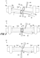
- FIG. 3 is an overall view of an anastomosis aid according to a second embodiment.
- FIG. 7 is an overall view of an anastomosis aid according to a third embodiment.
- FIG. 7 is an overall view of an anastomosis aid according to a fourth embodiment.
- each embodiment of the anastomosis aid of the present invention will be described in detail based on the drawings.
- the same components are given the same reference numerals, and overlapping explanations will be omitted.
- each embodiment of the present invention is not limited to each embodiment described below, and includes a long member inserted into a body canal and a distal end portion of the long member that has the effects of the present invention.
- the anastomosis aid may include all anastomosis aids having an extended extraction aid guide member.
- FIG. 1 is an overall view of an anastomosis aid 1 according to the first embodiment.
- An anastomosis aid 1 shown in FIG. 1 is used to prevent erroneous occlusion of a body canal during anastomosis of a body canal such as a blood vessel or lymphatic vessel by microscopic surgery.
- Such an anastomosis aid 1 includes an elongated member 10-1, a removal assisting guide member 20 fixed to the elongated member 10-1, and an adhesive 30.
- the elongated member 10-1 is used by being inserted into a body vessel such as a blood vessel or a lymphatic vessel.
- This elongated member 10-1 is hollow with at least one open end, and is cylindrical as shown, or has a cylindrical shape with one of both open ends closed. It is something that It is preferable that such an elongated member 10-1 is a member having a cylindrical outer diameter like that of a catheter, for example.
- the elongated member 10-1 is assumed to have enough rigidity to ensure the shape of the hollow portion. Further, the elongated member 10-1 preferably has flexibility to the extent that the hollow portion is crushed by an external force and the hollow portion is restored when the external force is removed, and is configured to be crushed and bent in the length direction. It is preferable that there be.
- the outer diameter [ ⁇ ] of the elongated member 10-1 is such that two elongated members 10-1 can be inserted into the elastic body canal with some margin, and It is set in various sizes depending on the size.
- the outer diameter [ ⁇ ] of the elongated member 10-1 is, for example, about 0.05 mm.
- the inner diameter and wall thickness of the elongated member 10-1 are not particularly limited, but should be large enough to ensure the elongated member 10-1 has flexibility while ensuring a hollow portion. do. Further, the elongated member 10-1 has an inner diameter large enough to allow insertion of a removal auxiliary guide member 20, which will be described next.
- the side into which the removal assisting guide member 20 is inserted will be referred to as the distal end 10a, and the opposite side will be referred to as the proximal end 10b.
- the end portion of the elongated member 10-1 is the bottom portion or the vicinity thereof with respect to the side circumference, and may include the periphery of the bottom portion to the extent that the effects of the present invention are not impaired.
- the length [L] of the elongated member 10-1 is a length that is easy to handle in microscopic surgery.
- the length [L] of the elongated member 10-1 is about 5 mm.
- the elongated member 10-1 has a sufficient length [L] exceeding 5 mm, and has a configuration that allows the operator of the anastomosis aid 1 to cut it to an appropriate length when using it. You can also use it as
- the elongated member 10-1 as described above may be made of a material used for medical purposes, and is made of resin or metal, for example.
- resin polyamide synthetic resin, silicone resin, polyvinylidene fluoride resin, polypropylene resin, polyester resin, etc. are used. If metal is used, stainless steel, titanium alloy, etc. are used.
- the elongated member 10-1 is made of resin.
- the removal auxiliary guide member 20 extends from the distal end 10a of the elongated member 10-1.
- the removal auxiliary guide member 20 is, for example, a thread-like member, and one end thereof is inserted into the elongated member 10-1 from the distal end 10a of the elongated member 10-1, and the other end thereof is inserted into the elongated member 10-1 from the distal end 10a of the elongated member 10-1. is arranged in a state extending from the tip 10a of the elongated member 10-1 to the outside of the elongated member 10-1. Further, the removal auxiliary guide member 20 is fixed to the elongated member 10-1 at the distal end 10a of the elongated member 10-1.
- the removal auxiliary guide member 20 has a thickness that can be inserted into the elongated member 10-1, and has a diameter of, for example, about 0.05 mm.
- the cross-sectional shape of the removal auxiliary guide member 20 is not limited, and may be a circle, an ellipse, a square, a rectangular shape, or a hollow cylinder.
- Such an extraction auxiliary guide member 20 may be a monofilament made of one fiber, or a monofilament made of a plurality of fibers, as long as it has enough strength that it will not break even when pulled with tweezers during microscopic surgery. It may also be a multifilament made of woven fibers. If the multifilament extraction assisting guide member 20 is used, it is possible to strengthen the fixation using the adhesive 30 described below.
- the extension length of the removal assisting guide member 20 from the elongated member 10-1 is set to a length that is easy to handle, so that the operator of the anastomosis assisting device 1 can cut it to an appropriate length when using it.
- This may be a possible configuration. For example, it is longer than the length [L] of the elongated member 10-1 when used for anastomosis.
- the insertion length of the removal auxiliary guide member 20 into the elongated member 10-1 is longer than the length at which sufficient adhesive strength with the elongated member 10-1 can be obtained by the adhesive 30 described below. That's it.
- the material of the removal auxiliary guide member 20 as described above is not particularly limited, but it is preferably a material that can be easily fixed to the elongated member 10-1 with the adhesive 30. It can be made of the same material as 1.
- the extraction assisting guide member 20 may be made of any material used for medical purposes, such as natural fibers including animal fibers such as silk and wool, and plant fibers such as cotton and linen, in addition to chemical fibers. It can be constructed using fibers. Further, for example, a medical thread can be used as the removal auxiliary guide member 20, but it is not limited to this because it is not left inside the body.
- the removal auxiliary guide member 20 has a folded portion 20a in which a protruding portion from the distal end 10a of the elongated member 10-1 is bent toward the proximal end 10b of the elongated member 10-1 in a direction opposite to the protruding direction. It is preferable that The folded portion 20a has flexibility, and is configured such that its bent shape can be canceled by pulling the distal end side of the removal auxiliary guide member 20 in the extending direction.
- the removal auxiliary guide member 20 when the removal auxiliary guide member 20 is made of resin, such a folded portion 20a can be formed by folding a part of the removal auxiliary guide member 20 and storing it in a low-temperature dryer for a certain period of time to give it a bent shape. It is formed by Further, when the removal auxiliary guide member 20 is made of metal, it is formed by hot working in which a part of the removal auxiliary guide member 20 is bent while applying heat, or by cold working in which it is bent without applying heat. In the case of cold working, heat treatment may be performed after bending to remove bending strain.
- the removal auxiliary guide member 20 is made of natural fibers (for example, silk)
- a part of the removal auxiliary guide member 20 is folded back, steam is applied to the folded part for a certain period of time, and then the folded part is heated in a drying oven to be dried.
- the folded portion 20a can be formed.
- the adhesive 30 is filled into the hollow of the elongated member 10-1 from the open end on the distal end 10a side of the elongated member 10-1, and fixes the removal auxiliary guide member 20 to the elongated member 10-1.
- an adhesive 30 can be injected into the hollow part of the elongated member 10-1 in an uncured liquid state, and hardens after being injected. -1, the removal auxiliary guide member 20 is fixed.
- Such an adhesive is appropriately selected depending on the materials of the elongated member 10-1 and the removal auxiliary guide member 20.
- a medical adhesive such as a cyanoacrylate adhesive can be used.
- the adhesive 30 may be a filler material that becomes liquid by heating and is introduced into the hollow portion of the elongated member 10-1. Such a filler metal hardens by cooling, thereby fixing the removal auxiliary guide member 20 to the elongated member 10-1.
- the filler material that becomes the adhesive 30 may be one that melts the elongated member 10-1 itself and closes the hollow portion by heating the end portion (tip 10a) of the elongated member 10-1. good.
- the edge of the removal auxiliary guide member 20 inserted into the elongated member 10-1 may be a free end protruding from the adhesive 30 within the elongated member 10-1.
- FIG. 2 is a diagram showing the manufacturing process of the anastomosis aid according to the first embodiment.
- a hollow elongated member 10-1 having, for example, a cylindrical shape is prepared.
- the long member 10-1 to be prepared may have a length [L] when used for anastomosis, or may have a longer length that is easier to handle.
- the removal auxiliary guide member 20 is inserted into the elongated member 10-1 through the opening at one end of the elongated member 10-1.
- the end of the elongated member 10-1 on the side into which the removal auxiliary guide member 20 is inserted becomes the tip 10a.
- the removal auxiliary guide member 20 is inserted into the elongated member 10-1 to a length that provides sufficient adhesive strength with the elongated member 10-1.
- the removal auxiliary guide member 20 may have the folded portion 20a already formed therein, but is not limited thereto.
- ⁇ Anastomosis procedure> 3 and 4 are schematic diagrams (part 1) and (part 2) for explaining an anastomosis procedure using the anastomosis assisting device 1 according to the first embodiment.
- FIGS. 3 and 4 a procedure for anastomosis of internal vessels such as blood vessels and lymph vessels using the anastomosis aid 1 having the above-described configuration will be described. Note that the procedure described below is performed by operations using the tweezers 101.
- both sides of the broken part [A] of the body canal [Ve] are fixed with clips 100 with the fractured surfaces [S] of the body canal [Ve] facing each other.
- the distal end 10a of the elongated member 10-1 in the anastomosis aid 1 is inserted into the body canal [Ve] from the broken part [A] of the body canal [Ve].
- the proximal end 10b of the elongated member 10-1 is inserted into the internal canal [Ve] in the direction opposite to the distal end 10a from the broken part [A] of the internal canal [Ve]. Insert into.
- the elongated member 10-1 is inserted across both sides of the broken part [A] of the body canal [Ve], and the removal auxiliary guide member 20 is pulled out from the broken part [A] of the body canal [Ve]. do. Note that the procedures in FIGS. 3(1) and 3(2) may be performed in reverse.
- the position of the clip 100 is adjusted and fixed so that the fractured surfaces [S] of the intracorporeal canal [Ve] meet, and the arrangement of the intracorporeal canal [Ve] is arranged.
- the removal auxiliary guide member 20 which has been pulled out of the intracorporeal canal [Ve] is pulled toward the proximal end 10b of the elongated member 10-1.
- the distal end 10a of the elongated member 10-1 is bent toward the proximal end 10b side, and the distal end 10a of the elongated member 10-1 is pulled out of the body canal [Ve] through the gap between the ligations made by the medical thread 102. .
- the elongated member 10-1 does not have flexibility, adjust the position of the clip 100 and pull the removal auxiliary guide member 20 toward the proximal end 10b of the elongated member 10-1. Good too. As a result, the distal end 10a of the elongated member 10-1 can be moved to the broken part [A] without bending the elongated member 10-1, and the intracorporeal canal [Ve ] The tip 10a of the elongated member 10-1 can be pulled out.
- the removal auxiliary guide member 20 is pulled while adjusting the direction, thereby moving the elongated member 10-1 between the ligation gap with the medical thread 102 and the internal canal [Ve]. Take it out and complete the anastomosis of the intracorporeal canal [Ve].
- the removal assisting guide member 20 is configured to extend from the distal end (tip 10a) of the elongated member 10-1.
- the direction in which the elongated member 10-1 is pulled can match the direction in which the distal end 10a of the elongated member 10-1 moves.
- the distal end (tip 10a) of the elongated member 10-1 is not caught in the ligated portion of the medical thread 102 at the fractured part [A] (see FIG. 4) after anastomosis. can be easily taken out of the body canal [Ve] from the tip 10a.
- the distal end 10a of the elongated member 10-1 is accurately guided by the removal auxiliary guide member 20 into the gap of the ligated part of the fractured part [A] after anastomosis, the distal end 10a of the elongated member 10-1 Also, the removal auxiliary guide member 20 will not damage the inner wall of the intracorporeal canal [Ve].
- FIG. 5 is an overall view of the anastomosis aid 2 according to the second embodiment.
- the anastomosis aid 2 of the second embodiment shown in this figure is a modification of the anastomosis aid 1 described in the first embodiment.
- the anastomosis aid 2 of the second embodiment differs from the anastomosis aid 1 described in the first embodiment in the fixing structure of the elongated member 10-2 and the removal assisting guide member 20. This is because no adhesive is used.
- the elongated member 10-2 is used by being inserted into a body vessel such as a blood vessel or a lymphatic vessel, and its shape, material, and dimensions may be the same as those of the first embodiment.
- FIG. 5 shows an elongated member 10-2 having a cylindrical shape with one open end closed
- the elongated member 10-2 is similar to the elongated member 10-2 shown in FIG. 1 in the first embodiment. Similar to -1, it may be cylindrical with open ends on both sides.
- This elongated member 10-2 has a distal end 10a at the end on the open end side and a proximal end 10b at the other end, and a removal auxiliary guide member 20 is inserted into the elongated member 10-2 from the distal end 10a.
- the elongated member 10-2 is crushed at its distal end 10a side into which the removal auxiliary guide member 20 is inserted, and is caulked, for example, by thermocompression bonding while holding the removal auxiliary guide member 20, so that the elongated member 10-2 becomes the removal auxiliary guide member. 20 is fixed.
- the removal auxiliary guide member 20 may be similar to the removal auxiliary guide member 20 of the first embodiment. However, if the elongated member 10-2 is made of the same material, the removal auxiliary guide member 20 and the elongated member 10-2 are easily fused together by thermocompression bonding. The fixed state of the member 20 becomes strong.
- the manufacturing method of the anastomosis aid 2 as described above is as follows: First, in the same manner as the procedure described in the first embodiment using FIG. Insert the removal auxiliary guide member 20 into the member 10-2. Thereafter, the distal end 10a side of the elongated member 10-2, into which the removal auxiliary guide member 20 has been inserted, is crimped, thereby caulking the distal end 10a side of the elongated member 10-2 while holding the removal auxiliary guide member 20. Ru. As a result, the removal auxiliary guide member 20 is fixed to the distal end 10a of the elongated member 10-2. Further, if the folded part 20a is not formed on the removal auxiliary guide member 20, the process for forming the folded part 20a after fixing the removal auxiliary guide member 20 to the elongated member 10-2 as necessary. to complete the anastomosis aid 2.
- the anastomosis procedure using such an anastomosis aid 2 is performed in the same manner as the procedure described using FIGS. 3 and 4 in the first embodiment.
- the anastomosis assisting device 2 of the second embodiment described above has a configuration in which the removal assisting guide member 20 is extended from the distal end (tip 10a) of the elongated member 10-2. You can get the same effect as the ingredients.
- FIG. 6 is an overall view of the anastomosis aid 3 according to the third embodiment.
- the difference between the anastomosis aid 3 of the third embodiment shown in this figure and the anastomosis aid 1 described in the first embodiment is that the elongated member 10-3 and the removal aid guide member 20' are made of the same material. It is a continuous, integral piece, and no adhesive is used to secure it.
- the elongated member 10-3 is used by being inserted into a body vessel such as a blood vessel or a lymphatic vessel, and its shape, material, and dimensions may be the same as those of the first embodiment.
- the elongated member 10-3 is not limited to a cylindrical shape or a cylindrical shape with one open end closed, but may be columnar as shown.
- the elongated member 10-3 has a hollow shape, so that it has elasticity and flexibility to be crushed in the radial direction, and easily crushed and bent in the length direction. Further, it is assumed that the elongated member 10-3 is made of a material that can be easily processed by heating.
- the removal auxiliary guide member 20' extends from the distal end 10a of the elongated member 10-3, and is formed as an integral body made of the same material as the elongated member 10-3. Therefore, if the elongated member 10-3 is of a single composition, the removal auxiliary guide member 20' has a monofilament structure made of one fiber. Further, if the elongated member 10-3 is made of a multifilament made of a plurality of fibers, the removal auxiliary guide member 20' is also made of a multifilament. Further, the removal auxiliary guide member 20' has a hollow shape if the elongated member 10-3 is cylindrical, and has a bulk shape if the elongated member 10-3 is columnar.
- such a removal auxiliary guide member 20' also has the same strength and dimensions as the removal auxiliary guide member of the first embodiment, and also has a folded portion 20a.
- An example of the first manufacturing method is injection molding using a mold. In this case, by using the entire mold that includes the elongated member 10-3 to the removal auxiliary guide member 20', the columnar elongated member 10-3 and the removal auxiliary guide member 20' are molded as one piece. An anastomosis aid 3 is obtained.
- a part for forming the folded part 20a is provided in a part for forming the part for the part to form the auxiliary part for removal guide member 20', thereby forming a part for forming the part to assist in removal 20' having a folded part 20a.
- a method using heat processing is exemplified.
- a hollow or columnar elongated material having the same diameter as the elongated member 10-3 is prepared, and the central portion of the elongated material is heated and pulled from both sides.
- the central portion of the long material is processed into a thin line.
- the hollow or columnar elongated member 10-3 is integrated with the removal auxiliary guide member 20' made up of the part processed into a thin line.
- Ingredient 3 is obtained.
- a method using grinding is exemplified.
- a columnar elongated material having the same diameter as the elongated member 10-3 is prepared, a part of the elongated material is processed into a thin wire shape by grinding, and the processed portion is removed from the auxiliary guide member 20'.
- An anastomosis aid 3 having the following properties is obtained. Even with this method, it is also possible to obtain two anastomosis aids 3 from one long material by cutting the ground portion of the long material with the ground portion set at the center.
- the anastomosis procedure using the anastomosis aid 3 manufactured in this way is carried out in the same manner as the procedure described using FIGS. 3 and 4 in the first embodiment.
- the anastomosis assisting device 3 of the third embodiment described above has a configuration in which the removal assisting guide member 20' extends from the distal end (tip 10a) of the elongated member 10-3. You can get the same effect as an auxiliary device. Further, this anastomosis aid 3 can be formed so that the outer diameter is gradually narrowed by hanging from the distal end (tip 10a) of the elongated member 10-3 to the removal assisting guide member 20'.
- the elongated member 10-3 when pulling the elongated member 10-3 out of the body canal [Ve] by pulling the removal auxiliary guide member 20', the elongated member It is possible to more reliably prevent the tip end 10a of the member 10-3 from getting caught, and it becomes possible to take out the elongated member 10-3 extremely smoothly.
- FIG. 7 is an overall view of the anastomosis aid 4 according to the fourth embodiment.
- the difference between the anastomosis aid 4 of the fourth embodiment shown in this figure and the anastomosis aid 1 described in the first embodiment is that the elongated member 10-4 is columnar, and the elongated member 10-4 is columnar. 4 and the removal auxiliary guide member 20 are fixed using no adhesive.
- the elongated member 10-4 is used by being inserted into a body vessel such as a blood vessel or a lymphatic vessel, and has a columnar shape.
- the external shape, material, and dimensions of such elongated member 10-4 may be the same as those of the first embodiment.
- the removal auxiliary guide member 20 may be similar to the removal auxiliary guide member 20 of the first embodiment.
- One edge side of the removal assisting guide member 20 is embedded in the columnar elongated member 10-4, thereby being fixed to the elongated member 10-4.
- An example of a method for manufacturing the anastomosis aid 4 as described above is injection molding using a mold.
- the mold is provided with a groove for placing the removal auxiliary guide member 20 so as to reach the hollow product portion for forming the elongated member 10-4. This laying groove communicates with the longitudinal end of the hollow product part for forming the elongated member 10-4.
- one end of the removal auxiliary guide member 20 is placed in the product part of the mold, and the intermediate part of the removal auxiliary guide member 20 is laid in the laying groove, and the elongated member 10 is placed in the product part of the mold.
- -Pour the constituent materials of 1.
- one edge side of the removal auxiliary guide member 20 is embedded in the component poured into the mold.
- a columnar elongated member 10-4 is formed, and one end edge side of the removal auxiliary guide member 20 is embedded in the elongated member 10-4 and integrated.
- An anastomosis aid 4 molded into this is obtained. Note that if the folded portion 20a is not formed on the removal auxiliary guide member 20, a process for forming the folded portion 20a on the removal auxiliary guide member 20 is performed as necessary.
- the anastomosis assisting device 4 of the fourth embodiment described above has a configuration in which the removal assisting guide member 20 is extended from the distal end (tip 10a) of the elongated member 10-4. You can get the same effect as the ingredients. Furthermore, due to the shape of the mold used in manufacturing the anastomosis aid 4, the anastomosis aid 4 is gradually pulled out by being hung from the distal end (tip 10a) of the elongated member 10-4 onto the removal aid guide member 20. It is possible to have a configuration with a narrower diameter.
- the elongated member 10-4 when pulling the elongated member 10-4 out of the body canal [Ve] by pulling the removal auxiliary guide member 20, the elongated member 10-4 It is possible to more reliably prevent the tip end 10a of -4 from getting caught, and it is possible to take out the elongated member 10-4 extremely smoothly.
Abstract
This anastomosis aid comprises a long member to be inserted into an intracorporeal tube and a removal aid guide member extended from a terminal end part of the long member.
Description
本発明は、顕微鏡下手術による血管やリンパ管などの体内管の吻合に用いられる吻合補助具に関する。
The present invention relates to an anastomosis aid used for anastomosis of internal vessels such as blood vessels and lymphatic vessels through microscopic surgery.
微小血管の吻合に際して用いられる吻合補助具に関し、下記非特許文献1には、「末端付近に11/0ナイロンステントを2回巻いて平らな結び目で縛った2/0ナイロンステント」が記載されている。
Regarding an anastomosis aid used for anastomosis of microvessels, the following non-patent document 1 describes a ``2/0 nylon stent in which a 11/0 nylon stent is wrapped twice around the distal end and tied with a flat knot.'' There is.
この補助具は、吻合部から微小血管内に2/0ナイロンステントを挿入し、11/0ナイロンステントの端部を吻合部から微小血管外に取り出した状態で用いられる。この状態において、微小血管の吻合部の断面同士を、2/0ナイロンステントの側周において会合させ、会合させた吻合部の3/4程度を医療用接着剤で接着する。その後、微小血管外に取り出した状態の11/0ナイロンステントの端部を引っ張ることで、吻合部における接着の隙間から、2/0ナイロンステントを微小血管外に取り出す。これにより、微小血管を接着剤によって閉塞することを防止しつつ、会合させた吻合部の断面を接着して吻合することができる。
This auxiliary tool is used with a 2/0 nylon stent inserted into a microvessel from the anastomosis and an end of the 11/0 nylon stent taken out of the microvessel from the anastomosis. In this state, the cross sections of the anastomoses of the microvessels are brought together at the side periphery of the 2/0 nylon stent, and approximately 3/4 of the brought together anastomoses are adhered with a medical adhesive. Thereafter, by pulling the end of the 11/0 nylon stent taken out of the microvessel, the 2/0 nylon stent is taken out of the microvessel through the adhesive gap at the anastomosis. Thereby, it is possible to adhere and anastomose the cross sections of the assembled anastomotic portions while preventing microvessels from being occluded by the adhesive.
しかしながら、上述した吻合補助具は、2/0ナイロンステントの末端付近に11/0ナイロンステントを巻き回して縛り付けた構成になっており、11/0ナイロンステントの側周から2/0ナイロンステントが延設された状態となる。このため、11/0ナイロンステントの引っ張り方向と、2/0ナイロンステントの先端の進行方向とが一致せず、微小血管内からス2/0ナイロンステントを取り出す際には、2/0ナイロンステントの先端部が、血管の内壁に引っかかることのないように、11/0ナイロンステントの引っ張り方向を狭い範囲で微調整する必要がある。
However, the above-mentioned anastomosis aid has a structure in which an 11/0 nylon stent is wound and tied around the end of a 2/0 nylon stent, and the 2/0 nylon stent is wrapped around the side of the 11/0 nylon stent. It will be in an extended state. For this reason, the pulling direction of the 11/0 nylon stent does not match the advancing direction of the tip of the 2/0 nylon stent, and when removing the 2/0 nylon stent from the microvessel, the 2/0 nylon stent must be It is necessary to finely adjust the pulling direction of the 11/0 nylon stent within a narrow range so that the tip of the stent does not get caught on the inner wall of the blood vessel.
そこで本発明は、吻合の後に管内から容易に取り出すことが可能な吻合補助具を提供することを目的とする。
Therefore, an object of the present invention is to provide an anastomosis aid that can be easily taken out from inside the canal after anastomosis.
このような目的を達成するための本発明は、体内管に挿入される長尺部材と、前記長尺部材の末端部から延設された抜去補助ガイド部材とを備えた吻合補助具である。
To achieve such an object, the present invention is an anastomosis aid comprising an elongated member to be inserted into a body canal and a removal assisting guide member extending from a distal end of the elongated member.
本発明により、吻合の後に管内から容易に取り出すことが可能な吻合補助具を提供することができる。
According to the present invention, it is possible to provide an anastomosis aid that can be easily taken out from inside the canal after anastomosis.
以下、本発明の吻合補助具に関する各実施形態を図面に基づいて詳細に説明する。なお、以下に説明する各実施形態において同一の構成要素には同一の符号を付し、重複する説明は省略する。また、本発明の各実施形態は、以下に説明する各実施形態に限定されるものではなく、本発明の効果を有する、体内管に挿入される長尺部材と前記長尺部材の末端部から延設された抜去補助ガイド部材とを備えた吻合補助具、全てを包含しうる。
Hereinafter, each embodiment of the anastomosis aid of the present invention will be described in detail based on the drawings. In addition, in each embodiment described below, the same components are given the same reference numerals, and overlapping explanations will be omitted. Further, each embodiment of the present invention is not limited to each embodiment described below, and includes a long member inserted into a body canal and a distal end portion of the long member that has the effects of the present invention. The anastomosis aid may include all anastomosis aids having an extended extraction aid guide member.
≪第1実施形態≫
図1は、第1実施形態に係る吻合補助具1の全体図である。図1に示す吻合補助具1は、顕微鏡下手術による血管やリンパ管などの体内管の吻合において、誤って体内管を閉塞することを防止するために用いられるものである。このような吻合補助具1は、長尺部材10-1と、長尺部材10-1に固定された抜去補助ガイド部材20と、接着剤30とを備えている。以下に、これらの構成を詳細に説明する。 ≪First embodiment≫
FIG. 1 is an overall view of ananastomosis aid 1 according to the first embodiment. An anastomosis aid 1 shown in FIG. 1 is used to prevent erroneous occlusion of a body canal during anastomosis of a body canal such as a blood vessel or lymphatic vessel by microscopic surgery. Such an anastomosis aid 1 includes an elongated member 10-1, a removal assisting guide member 20 fixed to the elongated member 10-1, and an adhesive 30. These configurations will be explained in detail below.
図1は、第1実施形態に係る吻合補助具1の全体図である。図1に示す吻合補助具1は、顕微鏡下手術による血管やリンパ管などの体内管の吻合において、誤って体内管を閉塞することを防止するために用いられるものである。このような吻合補助具1は、長尺部材10-1と、長尺部材10-1に固定された抜去補助ガイド部材20と、接着剤30とを備えている。以下に、これらの構成を詳細に説明する。 ≪First embodiment≫
FIG. 1 is an overall view of an
<長尺部材10-1>
長尺部材10-1は、血管やリンパ管などの体内管に挿入して用いられる。この長尺部材10-1は、少なくとも一方の末端部を開口端とした中空のものであって、図示したような筒状であるか、または筒状の両側開口端のうちの一方が閉塞されたものである。このような長尺部材10-1は、例えば外径形状がカテーテルのような円筒形状の部材であることが好ましい。 <Long member 10-1>
The elongated member 10-1 is used by being inserted into a body vessel such as a blood vessel or a lymphatic vessel. This elongated member 10-1 is hollow with at least one open end, and is cylindrical as shown, or has a cylindrical shape with one of both open ends closed. It is something that It is preferable that such an elongated member 10-1 is a member having a cylindrical outer diameter like that of a catheter, for example.
また長尺部材10-1は、中空部の形状を確保できる程度の剛性を有するものとする。
また長尺部材10-1は、外力によって中空部が潰れ、外力が外れることで中空部が復元される程度の可撓性を有するものであることが好ましく、長さ方向に潰れて折れ曲がる構成であることが好ましい。 Further, the elongated member 10-1 is assumed to have enough rigidity to ensure the shape of the hollow portion.
Further, the elongated member 10-1 preferably has flexibility to the extent that the hollow portion is crushed by an external force and the hollow portion is restored when the external force is removed, and is configured to be crushed and bent in the length direction. It is preferable that there be.
このような長尺部材10-1の外径[φ]は、伸縮性を有する体内管に2本分の長尺部材10-1が、多少の余裕をもって挿入可能な程度であり、体内管のサイズに合わせた様々な大きさに設定される。吻合対象となる体内管の吻合術がリンパ管静脈吻合術である場合、長尺部材10-1の外径[φ]は一例として0.05mm程度である。
The outer diameter [φ] of the elongated member 10-1 is such that two elongated members 10-1 can be inserted into the elastic body canal with some margin, and It is set in various sizes depending on the size. When the anastomosis technique for the internal vessels to be anastomized is lymphovenous anastomosis, the outer diameter [φ] of the elongated member 10-1 is, for example, about 0.05 mm.
長尺部材10-1の内径および肉厚は、特に限定されることはないが、長尺部材10-1が中空部を確保しつつも可撓性を発揮できる程度の大きさであるものとする。また、長尺部材10-1は、次に説明する抜去補助ガイド部材20の挿入が可能な程度の内径を有する。なお、以下においては、長尺部材10-1の両側の末端のうち、抜去補助ガイド部材20が挿入されている側を先端10a、これと逆側を基端10bと称する。また長尺部材10-1の末端部とは、側周に対しての底部もしくはその近辺であり、本発明の効果を損なわない範囲で底部の周辺を含み得る。
The inner diameter and wall thickness of the elongated member 10-1 are not particularly limited, but should be large enough to ensure the elongated member 10-1 has flexibility while ensuring a hollow portion. do. Further, the elongated member 10-1 has an inner diameter large enough to allow insertion of a removal auxiliary guide member 20, which will be described next. Hereinafter, of both ends of the elongated member 10-1, the side into which the removal assisting guide member 20 is inserted will be referred to as the distal end 10a, and the opposite side will be referred to as the proximal end 10b. Further, the end portion of the elongated member 10-1 is the bottom portion or the vicinity thereof with respect to the side circumference, and may include the periphery of the bottom portion to the extent that the effects of the present invention are not impaired.
また、長尺部材10-1の長さ[L]は、顕微鏡下手術において取り扱いが容易な長さであるものとする。一例として、長尺部材10-1の長さ[L]は5mm程度である。なお、長尺部材10-1は、5mmを超える十分な長さ[L]を有するものとし、吻合補助具1の取扱者が使用時において適宜の長さに切断して用いることが可能な構成としてもよい。
Furthermore, the length [L] of the elongated member 10-1 is a length that is easy to handle in microscopic surgery. As an example, the length [L] of the elongated member 10-1 is about 5 mm. The elongated member 10-1 has a sufficient length [L] exceeding 5 mm, and has a configuration that allows the operator of the anastomosis aid 1 to cut it to an appropriate length when using it. You can also use it as
以上のような長尺部材10-1は、医療用として用いられる素材から作成されるものであればよく、一例として樹脂または金属を用いて構成されたものである。樹脂であれば、ポリアミド合成樹脂、シリコン樹脂、ポリフッ化ビニリデン樹脂、ポリプロピレン樹脂、ポリエステル樹脂等が用いられる。また金属であれば、ステンレス鋼、チタン合金等が用いられる。特に、可撓性を有する長尺部材10-1の場合には、長尺部材10-1は、樹脂によって構成されていることが好ましい。
The elongated member 10-1 as described above may be made of a material used for medical purposes, and is made of resin or metal, for example. As for the resin, polyamide synthetic resin, silicone resin, polyvinylidene fluoride resin, polypropylene resin, polyester resin, etc. are used. If metal is used, stainless steel, titanium alloy, etc. are used. In particular, in the case of the elongated member 10-1 having flexibility, it is preferable that the elongated member 10-1 is made of resin.
<抜去補助ガイド部材20>
抜去補助ガイド部材20は、長尺部材10-1の先端10aから延設されたものである。このような抜去補助ガイド部材20は、例えば糸状の部材であって、一方の端縁側が、長尺部材10-1の先端10aから長尺部材10-1の内部に挿入され、他方の端縁側が長尺部材10-1の先端10aから長尺部材10-1の外に延設された状態で配置される。また抜去補助ガイド部材20は、長尺部材10-1の先端10aにおいて、長尺部材10-1に固定されている。 <Removalauxiliary guide member 20>
The removalauxiliary guide member 20 extends from the distal end 10a of the elongated member 10-1. The removal auxiliary guide member 20 is, for example, a thread-like member, and one end thereof is inserted into the elongated member 10-1 from the distal end 10a of the elongated member 10-1, and the other end thereof is inserted into the elongated member 10-1 from the distal end 10a of the elongated member 10-1. is arranged in a state extending from the tip 10a of the elongated member 10-1 to the outside of the elongated member 10-1. Further, the removal auxiliary guide member 20 is fixed to the elongated member 10-1 at the distal end 10a of the elongated member 10-1.
抜去補助ガイド部材20は、長尺部材10-1の先端10aから延設されたものである。このような抜去補助ガイド部材20は、例えば糸状の部材であって、一方の端縁側が、長尺部材10-1の先端10aから長尺部材10-1の内部に挿入され、他方の端縁側が長尺部材10-1の先端10aから長尺部材10-1の外に延設された状態で配置される。また抜去補助ガイド部材20は、長尺部材10-1の先端10aにおいて、長尺部材10-1に固定されている。 <Removal
The removal
このような抜去補助ガイド部材20は、長尺部材10-1の内部に挿入される太さのものであり、例えば直径0.05mm程度のものである。また抜去補助ガイド部材20は、その断面形状が限定されることはなく、円、楕円、角形、平角形状の何れであってもよく、また中空の筒状であってもよい。このような抜去補助ガイド部材20は、顕微鏡下手術においてピンセットで引っ張っても破断しない程度の強さを有していれば、1本の繊維からなるモノフィラメントのものであってもよいし、複数本の繊維を編んだマルチフィラメントのものであってもよい。マルチフィラメントの抜去補助ガイド部材20であれば、次に説明する接着剤30による固定を強固にすることができる。
The removal auxiliary guide member 20 has a thickness that can be inserted into the elongated member 10-1, and has a diameter of, for example, about 0.05 mm. Further, the cross-sectional shape of the removal auxiliary guide member 20 is not limited, and may be a circle, an ellipse, a square, a rectangular shape, or a hollow cylinder. Such an extraction auxiliary guide member 20 may be a monofilament made of one fiber, or a monofilament made of a plurality of fibers, as long as it has enough strength that it will not break even when pulled with tweezers during microscopic surgery. It may also be a multifilament made of woven fibers. If the multifilament extraction assisting guide member 20 is used, it is possible to strengthen the fixation using the adhesive 30 described below.
また長尺部材10-1からの抜去補助ガイド部材20の延設長さは、取り扱いが容易な長さとし、吻合補助具1の取扱者が使用時において適宜の長さに切断して用いることが可能な構成としてもよい。一例として吻合の際の使用時における長尺部材10-1の長さ[L]よりも長い。一方、長尺部材10-1内への抜去補助ガイド部材20の挿入長さは、次に説明する接着剤30による長尺部材10-1との接着強度が十分に得られる長さ以上であることとする。
In addition, the extension length of the removal assisting guide member 20 from the elongated member 10-1 is set to a length that is easy to handle, so that the operator of the anastomosis assisting device 1 can cut it to an appropriate length when using it. This may be a possible configuration. For example, it is longer than the length [L] of the elongated member 10-1 when used for anastomosis. On the other hand, the insertion length of the removal auxiliary guide member 20 into the elongated member 10-1 is longer than the length at which sufficient adhesive strength with the elongated member 10-1 can be obtained by the adhesive 30 described below. That's it.
以上のような抜去補助ガイド部材20の材質は特に限定されることはないが、接着剤30によって長尺部材10-1に対して固定し易い材質であることが好ましく、例えば長尺部材10-1と同一の材料で構成することができる。さらに抜去補助ガイド部材20は、医療用として用いられる素材から作成されるものであればよく、例えば、化学繊維の他に、シルク、羊毛などの動物繊維、綿、麻などの植物繊維を含む天然繊維を用いて構成することができる。また、抜去補助ガイド部材20として、例えば医療用糸を用いることができるが、体内に残されるものではないため、これに限定されることはない。
The material of the removal auxiliary guide member 20 as described above is not particularly limited, but it is preferably a material that can be easily fixed to the elongated member 10-1 with the adhesive 30. It can be made of the same material as 1. Furthermore, the extraction assisting guide member 20 may be made of any material used for medical purposes, such as natural fibers including animal fibers such as silk and wool, and plant fibers such as cotton and linen, in addition to chemical fibers. It can be constructed using fibers. Further, for example, a medical thread can be used as the removal auxiliary guide member 20, but it is not limited to this because it is not left inside the body.
また抜去補助ガイド部材20は、長尺部材10-1の先端10aからの突出部分が、長尺部材10-1の基端10b側に向かって、突出方向とは逆方向に屈曲した折り返し部20aとなっていることが好ましい。この折り返し部20aは、柔軟性を有し、抜去補助ガイド部材20の延設方向の先端側を引っ張ることで屈曲形状が解消される構成である。
Further, the removal auxiliary guide member 20 has a folded portion 20a in which a protruding portion from the distal end 10a of the elongated member 10-1 is bent toward the proximal end 10b of the elongated member 10-1 in a direction opposite to the protruding direction. It is preferable that The folded portion 20a has flexibility, and is configured such that its bent shape can be canceled by pulling the distal end side of the removal auxiliary guide member 20 in the extending direction.
このような折り返し部20aは、例えば抜去補助ガイド部材20が樹脂からなる場合、抜去補助ガイド部材20の一部を折り返した形状として低温乾燥器に一定時間保存することにより、折り返した形状を癖付けすることで形成される。また、抜去補助ガイド部材20が金属からなる場合、抜去補助ガイド部材20の一部に熱を加えつつ屈曲させる熱間加工、または熱を加えず屈曲させる冷間加工によって形成される。冷間加工の場合、曲げ歪みをとるために、屈曲後に熱処理を行うこともある。また抜去補助ガイド部材20が天然繊維(例えばシルク)の場合、抜去補助ガイド部材20の一部を折り返した形状とし、その折り返し部に一定時間蒸気をあて、その後、乾燥炉に入れて乾燥させることで、折り返し部20aを形成することができる。
For example, when the removal auxiliary guide member 20 is made of resin, such a folded portion 20a can be formed by folding a part of the removal auxiliary guide member 20 and storing it in a low-temperature dryer for a certain period of time to give it a bent shape. It is formed by Further, when the removal auxiliary guide member 20 is made of metal, it is formed by hot working in which a part of the removal auxiliary guide member 20 is bent while applying heat, or by cold working in which it is bent without applying heat. In the case of cold working, heat treatment may be performed after bending to remove bending strain. In addition, when the removal auxiliary guide member 20 is made of natural fibers (for example, silk), a part of the removal auxiliary guide member 20 is folded back, steam is applied to the folded part for a certain period of time, and then the folded part is heated in a drying oven to be dried. Thus, the folded portion 20a can be formed.
<接着剤30>
接着剤30は、長尺部材10-1の先端10a側の開口端から長尺部材10-1の中空内に充填され、抜去補助ガイド部材20を長尺部材10-1に固定する。このような接着剤30は、一例として未硬化の液体状において、長尺部材10-1の中空部に注入可能であって、注入後に硬化するものであり、この接着剤30により長尺部材10-1に対して抜去補助ガイド部材20が固定される。このような接着剤は、長尺部材10-1および抜去補助ガイド部材20の材質によって適宜に選択された材質のものが用いられる。一例として、長尺部材10-1がポリアミド合成樹脂からなるものである場合には、例えばシアノアクリレート系接着剤のような医療用の接着剤を用いることができる。 <Adhesive 30>
The adhesive 30 is filled into the hollow of the elongated member 10-1 from the open end on thedistal end 10a side of the elongated member 10-1, and fixes the removal auxiliary guide member 20 to the elongated member 10-1. For example, such an adhesive 30 can be injected into the hollow part of the elongated member 10-1 in an uncured liquid state, and hardens after being injected. -1, the removal auxiliary guide member 20 is fixed. Such an adhesive is appropriately selected depending on the materials of the elongated member 10-1 and the removal auxiliary guide member 20. For example, if the elongated member 10-1 is made of polyamide synthetic resin, a medical adhesive such as a cyanoacrylate adhesive can be used.
接着剤30は、長尺部材10-1の先端10a側の開口端から長尺部材10-1の中空内に充填され、抜去補助ガイド部材20を長尺部材10-1に固定する。このような接着剤30は、一例として未硬化の液体状において、長尺部材10-1の中空部に注入可能であって、注入後に硬化するものであり、この接着剤30により長尺部材10-1に対して抜去補助ガイド部材20が固定される。このような接着剤は、長尺部材10-1および抜去補助ガイド部材20の材質によって適宜に選択された材質のものが用いられる。一例として、長尺部材10-1がポリアミド合成樹脂からなるものである場合には、例えばシアノアクリレート系接着剤のような医療用の接着剤を用いることができる。 <
The adhesive 30 is filled into the hollow of the elongated member 10-1 from the open end on the
また接着剤30は、加熱によって液体状となり、長尺部材10-1の中空部に導入される溶加材を用いることもできる。このような溶加材は、冷却によって硬化し、これにより抜去補助ガイド部材20を長尺部材10-1に固定する。また接着剤30となる溶加材は、長尺部材10-1の末端部(先端10a)を加熱することで、長尺部材10-1自体が溶融して中空部を塞ぐものであってもよい。なお、長尺部材10-1内に挿入された抜去補助ガイド部材20の端縁は、長尺部材10-1内において接着剤30から突出している自由端となっていてよい。
Alternatively, the adhesive 30 may be a filler material that becomes liquid by heating and is introduced into the hollow portion of the elongated member 10-1. Such a filler metal hardens by cooling, thereby fixing the removal auxiliary guide member 20 to the elongated member 10-1. Further, the filler material that becomes the adhesive 30 may be one that melts the elongated member 10-1 itself and closes the hollow portion by heating the end portion (tip 10a) of the elongated member 10-1. good. Note that the edge of the removal auxiliary guide member 20 inserted into the elongated member 10-1 may be a free end protruding from the adhesive 30 within the elongated member 10-1.
<吻合補助具1の製造方法>
図2は、第1実施形態に係る吻合補助具の製造工程を示す図である。先ず、図2(1)に示すように、例えば円筒形状であって、中空の長尺部材10-1を用意する。用意する長尺部材10-1は、吻合の際の使用時の長さ[L]のものでもよいし、それよりも長く取り扱いが容易な長さのものでもよい。 <Method formanufacturing anastomosis aid 1>
FIG. 2 is a diagram showing the manufacturing process of the anastomosis aid according to the first embodiment. First, as shown in FIG. 2(1), a hollow elongated member 10-1 having, for example, a cylindrical shape is prepared. The long member 10-1 to be prepared may have a length [L] when used for anastomosis, or may have a longer length that is easier to handle.
図2は、第1実施形態に係る吻合補助具の製造工程を示す図である。先ず、図2(1)に示すように、例えば円筒形状であって、中空の長尺部材10-1を用意する。用意する長尺部材10-1は、吻合の際の使用時の長さ[L]のものでもよいし、それよりも長く取り扱いが容易な長さのものでもよい。 <Method for
FIG. 2 is a diagram showing the manufacturing process of the anastomosis aid according to the first embodiment. First, as shown in FIG. 2(1), a hollow elongated member 10-1 having, for example, a cylindrical shape is prepared. The long member 10-1 to be prepared may have a length [L] when used for anastomosis, or may have a longer length that is easier to handle.
次に図2(2)に示すように、長尺部材10-1の一方側の末端部の開口から、長尺部材10-1内に抜去補助ガイド部材20を挿入する。長尺部材10-1において、抜去補助ガイド部材20を挿入した側の末端部が、先端10aとなる。この際、長尺部材10-1内には、長尺部材10-1との接着強度が十分に得られる長さで抜去補助ガイド部材20を挿入される。また、抜去補助ガイド部材20は、既に折り返し部20aが形成されたものでもよいが、これに限定されることはない。
Next, as shown in FIG. 2(2), the removal auxiliary guide member 20 is inserted into the elongated member 10-1 through the opening at one end of the elongated member 10-1. The end of the elongated member 10-1 on the side into which the removal auxiliary guide member 20 is inserted becomes the tip 10a. At this time, the removal auxiliary guide member 20 is inserted into the elongated member 10-1 to a length that provides sufficient adhesive strength with the elongated member 10-1. Further, the removal auxiliary guide member 20 may have the folded portion 20a already formed therein, but is not limited thereto.
その後、図1に示したように、筒状の長尺部材10-1において、抜去補助ガイド部材20を挿入した側(すなわち先端10a側)から、長尺部材10-1の内部に未硬化の接着剤30を注入し、その後、接着剤30を硬化させる。また、接着剤30として、溶加材を用いる場合、抜去補助ガイド部材20を挿入した側(すなわち先端10a側)から、長尺部材10-1の内部に加熱して液状化させた溶加材を導入し、長尺部材10-1と抜去補助ガイド部材20とを溶接する。この溶接においては、必要に応じて長尺部材10-1と抜去補助ガイド部材20との接着部分の加熱および加圧を実施する。
Thereafter, as shown in FIG. 1, from the side into which the removal auxiliary guide member 20 is inserted (i.e., the tip 10a side) of the cylindrical elongated member 10-1, uncured material is added to the inside of the elongated member 10-1. The adhesive 30 is injected, and then the adhesive 30 is cured. In addition, when a filler material is used as the adhesive 30, the filler material is heated and liquefied into the elongated member 10-1 from the side where the removal auxiliary guide member 20 is inserted (i.e., the tip end 10a side). is introduced, and the elongated member 10-1 and the removal auxiliary guide member 20 are welded together. In this welding, the bonded portion between the elongated member 10-1 and the removal auxiliary guide member 20 is heated and pressurized as necessary.
以上の後、抜去補助ガイド部材20に折り返し部20aが形成されていない場合であれば、必要に応じて接着剤30が硬化した後に、折り返し部20aを形成するための処理を施し、吻合補助具1を完成させる。
After the above, if the folded part 20a is not formed on the removal auxiliary guide member 20, after the adhesive 30 has hardened as necessary, a process for forming the folded part 20a is performed, and the anastomosis aid Complete 1.
<吻合の手順>
図3および図4は、第1実施形態に係る吻合補助具1を用いた吻合手順を説明するための模式図(その1)および(その2)である。以下、これらの図3および図4に基づいて、上述した構成の吻合補助具1を用いた血管やリンパ管などの体内管の吻合手順を説明する。なお、以下に説明する手順は、ピンセット101を用いての操作によって実施される。 <Anastomosis procedure>
3 and 4 are schematic diagrams (part 1) and (part 2) for explaining an anastomosis procedure using theanastomosis assisting device 1 according to the first embodiment. Hereinafter, based on these FIGS. 3 and 4, a procedure for anastomosis of internal vessels such as blood vessels and lymph vessels using the anastomosis aid 1 having the above-described configuration will be described. Note that the procedure described below is performed by operations using the tweezers 101.
図3および図4は、第1実施形態に係る吻合補助具1を用いた吻合手順を説明するための模式図(その1)および(その2)である。以下、これらの図3および図4に基づいて、上述した構成の吻合補助具1を用いた血管やリンパ管などの体内管の吻合手順を説明する。なお、以下に説明する手順は、ピンセット101を用いての操作によって実施される。 <Anastomosis procedure>
3 and 4 are schematic diagrams (part 1) and (part 2) for explaining an anastomosis procedure using the
先ず、図3(1)に示すように、体内管[Ve]の破断面[S]同士を向かい合わせた状態で、体内管[Ve]の破断部[A]の両側をクリップ100で固定する。次に、吻合補助具1における長尺部材10-1の先端10aを、体内管[Ve]の破断部[A]から体内管[Ve]内に挿入する。この際、抜去補助ガイド部材20において、長尺部材10-1の先端10aから突出した部分が、折り返し部20aとして長尺部材10-1の基端10b側に折れ曲がっていれば、抜去補助ガイド部材20が邪魔になることがなく、体内管[Ve]内への長尺部材10-1の挿入をスムーズに行うことができる。
First, as shown in FIG. 3(1), both sides of the broken part [A] of the body canal [Ve] are fixed with clips 100 with the fractured surfaces [S] of the body canal [Ve] facing each other. . Next, the distal end 10a of the elongated member 10-1 in the anastomosis aid 1 is inserted into the body canal [Ve] from the broken part [A] of the body canal [Ve]. At this time, if the part of the removal auxiliary guide member 20 that protrudes from the distal end 10a of the elongated member 10-1 is bent toward the proximal end 10b of the elongated member 10-1 as a folded portion 20a, the removal auxiliary guide member 20 20 does not get in the way, and the elongated member 10-1 can be smoothly inserted into the intracorporeal canal [Ve].
次に、図3(2)に示すように、長尺部材10-1の基端10bを、体内管[Ve]の破断部[A]から先端10aとは逆方向の体内管[Ve]内に挿入する。これにより、体内管[Ve]の破断部[A]の両側にわたって長尺部材10-1を挿入し、体内管[Ve]の破断部[A]から抜去補助ガイド部材20が引き出された状態とする。なお、図3(1)と図3(2)の手順は逆に実施してもよい。
Next, as shown in FIG. 3(2), the proximal end 10b of the elongated member 10-1 is inserted into the internal canal [Ve] in the direction opposite to the distal end 10a from the broken part [A] of the internal canal [Ve]. Insert into. As a result, the elongated member 10-1 is inserted across both sides of the broken part [A] of the body canal [Ve], and the removal auxiliary guide member 20 is pulled out from the broken part [A] of the body canal [Ve]. do. Note that the procedures in FIGS. 3(1) and 3(2) may be performed in reverse.
その後、図3(3)に示すように、体内管[Ve]の破断面[S]同士が会合するように、クリップ100を位置調整して固定し、体内管[Ve]の配置を整える。
Thereafter, as shown in FIG. 3 (3), the position of the clip 100 is adjusted and fixed so that the fractured surfaces [S] of the intracorporeal canal [Ve] meet, and the arrangement of the intracorporeal canal [Ve] is arranged.
次いで、図4(1)に示すように、体内管[Ve]の破断部[A]の複数個所を、医療用糸102で結紮し、体内管[Ve]を吻合する。この際、体内管[Ve]の全周にわたって吻合補助具1の長尺部材10-1が下地となるので、誤って体内管[Ve]の径方向が結紮されて閉塞することを防止できる。なお、この吻合は、医療用接着剤を用いて実施されてもよい。この場合には、破断部[A]を全周にわたって接着させず、長尺部材[Ve]を取り出すための隙間を設けておく必要がある。
Next, as shown in FIG. 4(1), multiple locations of the fractured part [A] of the intracorporeal tube [Ve] are ligated with the medical thread 102, and the intracorporeal tube [Ve] is anastomosed. At this time, since the elongated member 10-1 of the anastomosis aid 1 serves as a base over the entire circumference of the body canal [Ve], it is possible to prevent the body canal [Ve] from being accidentally ligated and occluded in the radial direction. Note that this anastomosis may be performed using a medical adhesive. In this case, it is necessary not to adhere the broken part [A] all around the circumference, but to provide a gap for taking out the elongated member [Ve].
その後、図4(2)に示すように、体内管[Ve]の外に引き出されている抜去補助ガイド部材20を長尺部材10-1の基端10b側に引っ張る。これにより、長尺部材10-1の先端10aを基端10b側に屈曲させ、長尺部材10-1の先端10aを医療用糸102による結紮の隙間から、体内管[Ve]の外に引き出す。
Thereafter, as shown in FIG. 4(2), the removal auxiliary guide member 20, which has been pulled out of the intracorporeal canal [Ve], is pulled toward the proximal end 10b of the elongated member 10-1. As a result, the distal end 10a of the elongated member 10-1 is bent toward the proximal end 10b side, and the distal end 10a of the elongated member 10-1 is pulled out of the body canal [Ve] through the gap between the ligations made by the medical thread 102. .
なお、長尺部材10-1が、可撓性を有していない場合には、クリップ100の位置を調整し、抜去補助ガイド部材20を長尺部材10-1の基端10b側に引っ張ってもよい。これにより、長尺部材10-1を屈曲させることなく、長尺部材10-1の先端10aを破断部[A]に移動させることができ、医療用糸102による結紮の隙間から体内管[Ve]の外に、長尺部材10-1の先端10aを引き出すことができる。
Note that if the elongated member 10-1 does not have flexibility, adjust the position of the clip 100 and pull the removal auxiliary guide member 20 toward the proximal end 10b of the elongated member 10-1. Good too. As a result, the distal end 10a of the elongated member 10-1 can be moved to the broken part [A] without bending the elongated member 10-1, and the intracorporeal canal [Ve ] The tip 10a of the elongated member 10-1 can be pulled out.
さらに、図4(3)に示すように、方向を調整しながら抜去補助ガイド部材20を引っ張り、これにより、長尺部材10-1を医療用糸102による結紮の隙間か体内管[Ve]の外に取り出し、体内管[Ve]の吻合を完了させる。
Furthermore, as shown in FIG. 4(3), the removal auxiliary guide member 20 is pulled while adjusting the direction, thereby moving the elongated member 10-1 between the ligation gap with the medical thread 102 and the internal canal [Ve]. Take it out and complete the anastomosis of the intracorporeal canal [Ve].
<第1実施形態の効果>
以上説明した第1実施形態の吻合補助具1によれば、長尺部材10-1の末端部(先端10a)から抜去補助ガイド部材20を延設した構成であることにより、抜去補助ガイド部材20を引っ張る方向と、長尺部材10-1の先端10aの進行方向とを一致させることができる。これにより、吻合後に体内管[Ve]の外側から抜去補助ガイド部材20を引っ張ることで、長尺部材10-1の末端部(先端10a)を、結紮部分の隙間に正確に誘導することが可能となる。この結果、長尺部材10-1の末端部(先端10a)を、吻合後の破断部[A](図4参照)における医療用糸102による結紮部分に引っ掛けることなく、長尺部材10-1を先端10aから体内管[Ve]の外に容易に取り出すことが可能となる。 <Effects of the first embodiment>
According to theanastomosis assisting device 1 of the first embodiment described above, the removal assisting guide member 20 is configured to extend from the distal end (tip 10a) of the elongated member 10-1. The direction in which the elongated member 10-1 is pulled can match the direction in which the distal end 10a of the elongated member 10-1 moves. As a result, by pulling the removal auxiliary guide member 20 from the outside of the body canal [Ve] after anastomosis, it is possible to accurately guide the distal end (tip 10a) of the elongated member 10-1 into the gap between the ligated parts. becomes. As a result, the distal end (tip 10a) of the elongated member 10-1 is not caught in the ligated portion of the medical thread 102 at the fractured part [A] (see FIG. 4) after anastomosis. can be easily taken out of the body canal [Ve] from the tip 10a.
以上説明した第1実施形態の吻合補助具1によれば、長尺部材10-1の末端部(先端10a)から抜去補助ガイド部材20を延設した構成であることにより、抜去補助ガイド部材20を引っ張る方向と、長尺部材10-1の先端10aの進行方向とを一致させることができる。これにより、吻合後に体内管[Ve]の外側から抜去補助ガイド部材20を引っ張ることで、長尺部材10-1の末端部(先端10a)を、結紮部分の隙間に正確に誘導することが可能となる。この結果、長尺部材10-1の末端部(先端10a)を、吻合後の破断部[A](図4参照)における医療用糸102による結紮部分に引っ掛けることなく、長尺部材10-1を先端10aから体内管[Ve]の外に容易に取り出すことが可能となる。 <Effects of the first embodiment>
According to the
さらに、長尺部材10-1の先端10aは、抜去補助ガイド部材20によって、吻合後の破断部[A]の結紮部分の隙間に正確に誘導されるため、長尺部材10-1の先端10aや抜去補助ガイド部材20が体内管[Ve]の内壁を傷つけることもない。
Furthermore, since the distal end 10a of the elongated member 10-1 is accurately guided by the removal auxiliary guide member 20 into the gap of the ligated part of the fractured part [A] after anastomosis, the distal end 10a of the elongated member 10-1 Also, the removal auxiliary guide member 20 will not damage the inner wall of the intracorporeal canal [Ve].
≪第2実施形態≫
図5は、第2実施形態に係る吻合補助具2の全体図である。この図に示す第2実施形態の吻合補助具2は、第1実施形態で説明した吻合補助具1の変形例である。第2実施形態の吻合補助具2が、第1実施形態で説明した吻合補助具1と異なるところは、長尺部材10-2と抜去補助ガイド部材20との固定構造にあり、これらの固定に接着剤を用いていないところにある。 ≪Second embodiment≫
FIG. 5 is an overall view of theanastomosis aid 2 according to the second embodiment. The anastomosis aid 2 of the second embodiment shown in this figure is a modification of the anastomosis aid 1 described in the first embodiment. The anastomosis aid 2 of the second embodiment differs from the anastomosis aid 1 described in the first embodiment in the fixing structure of the elongated member 10-2 and the removal assisting guide member 20. This is because no adhesive is used.
図5は、第2実施形態に係る吻合補助具2の全体図である。この図に示す第2実施形態の吻合補助具2は、第1実施形態で説明した吻合補助具1の変形例である。第2実施形態の吻合補助具2が、第1実施形態で説明した吻合補助具1と異なるところは、長尺部材10-2と抜去補助ガイド部材20との固定構造にあり、これらの固定に接着剤を用いていないところにある。 ≪Second embodiment≫
FIG. 5 is an overall view of the
<長尺部材10-2>
長尺部材10-2は、血管やリンパ管などの体内管に挿入して用いられるものであり、形状、材質、寸法は、第1実施形態のものと同様であってよい。図5では、筒状の一方の開口端が閉塞された形状の長尺部材10-2を示したが、長尺部材10-2は、第1実施形態において図1に示した長尺部材10-1と同様に、両側の末端を開口端とした筒状のものであってもよい。 <Long member 10-2>
The elongated member 10-2 is used by being inserted into a body vessel such as a blood vessel or a lymphatic vessel, and its shape, material, and dimensions may be the same as those of the first embodiment. Although FIG. 5 shows an elongated member 10-2 having a cylindrical shape with one open end closed, the elongated member 10-2 is similar to the elongated member 10-2 shown in FIG. 1 in the first embodiment. Similar to -1, it may be cylindrical with open ends on both sides.
この長尺部材10-2は、開口端側の末端を先端10aとし、他方の末端を基端10bとし、先端10aから長尺部材10-2内に抜去補助ガイド部材20が挿入されている。
長尺部材10-2は、抜去補助ガイド部材20が挿入されている先端10a側が押し潰され、抜去補助ガイド部材20を挟持した状態で、例えば熱圧着によってカシメられたことにより、抜去補助ガイド部材20が固定される。 This elongated member 10-2 has adistal end 10a at the end on the open end side and a proximal end 10b at the other end, and a removal auxiliary guide member 20 is inserted into the elongated member 10-2 from the distal end 10a.
The elongated member 10-2 is crushed at itsdistal end 10a side into which the removal auxiliary guide member 20 is inserted, and is caulked, for example, by thermocompression bonding while holding the removal auxiliary guide member 20, so that the elongated member 10-2 becomes the removal auxiliary guide member. 20 is fixed.
長尺部材10-2は、抜去補助ガイド部材20が挿入されている先端10a側が押し潰され、抜去補助ガイド部材20を挟持した状態で、例えば熱圧着によってカシメられたことにより、抜去補助ガイド部材20が固定される。 This elongated member 10-2 has a
The elongated member 10-2 is crushed at its
<抜去補助ガイド部材20>
抜去補助ガイド部材20は、第1実施形態の抜去補助ガイド部材20と同様のものでよい。ただし、長尺部材10-2と同様の材質のものであれば、熱圧着によって抜去補助ガイド部材20と長尺部材10-2とが融合し易いため、長尺部材10-2に対する抜去補助ガイド部材20の固定状態が強固となる。 <Removalauxiliary guide member 20>
The removalauxiliary guide member 20 may be similar to the removal auxiliary guide member 20 of the first embodiment. However, if the elongated member 10-2 is made of the same material, the removal auxiliary guide member 20 and the elongated member 10-2 are easily fused together by thermocompression bonding. The fixed state of the member 20 becomes strong.
抜去補助ガイド部材20は、第1実施形態の抜去補助ガイド部材20と同様のものでよい。ただし、長尺部材10-2と同様の材質のものであれば、熱圧着によって抜去補助ガイド部材20と長尺部材10-2とが融合し易いため、長尺部材10-2に対する抜去補助ガイド部材20の固定状態が強固となる。 <Removal
The removal
<吻合補助具2の製造方法>
以上のような吻合補助具2の製造方法は、先ず、第1実施形態において図2を用いて説明した手順と同様にして、長尺部材10-2の一方側の末端部の開口から長尺部材10-2内に抜去補助ガイド部材20を挿入する。その後、長尺部材10-2において、抜去補助ガイド部材20が挿入された先端10a側を圧着することにより、抜去補助ガイド部材20を挟持した状態で長尺部材10-2の先端10a側をカシメる。これにより、長尺部材10-2の先端10aに抜去補助ガイド部材20を固定する。また抜去補助ガイド部材20に折り返し部20aが形成されていない場合であれば、必要に応じて長尺部材10-2に抜去補助ガイド部材20を固定した後に、折り返し部20aを形成するための処理を施し、吻合補助具2を完成させる。 <Method formanufacturing anastomosis aid 2>
The manufacturing method of theanastomosis aid 2 as described above is as follows: First, in the same manner as the procedure described in the first embodiment using FIG. Insert the removal auxiliary guide member 20 into the member 10-2. Thereafter, the distal end 10a side of the elongated member 10-2, into which the removal auxiliary guide member 20 has been inserted, is crimped, thereby caulking the distal end 10a side of the elongated member 10-2 while holding the removal auxiliary guide member 20. Ru. As a result, the removal auxiliary guide member 20 is fixed to the distal end 10a of the elongated member 10-2. Further, if the folded part 20a is not formed on the removal auxiliary guide member 20, the process for forming the folded part 20a after fixing the removal auxiliary guide member 20 to the elongated member 10-2 as necessary. to complete the anastomosis aid 2.
以上のような吻合補助具2の製造方法は、先ず、第1実施形態において図2を用いて説明した手順と同様にして、長尺部材10-2の一方側の末端部の開口から長尺部材10-2内に抜去補助ガイド部材20を挿入する。その後、長尺部材10-2において、抜去補助ガイド部材20が挿入された先端10a側を圧着することにより、抜去補助ガイド部材20を挟持した状態で長尺部材10-2の先端10a側をカシメる。これにより、長尺部材10-2の先端10aに抜去補助ガイド部材20を固定する。また抜去補助ガイド部材20に折り返し部20aが形成されていない場合であれば、必要に応じて長尺部材10-2に抜去補助ガイド部材20を固定した後に、折り返し部20aを形成するための処理を施し、吻合補助具2を完成させる。 <Method for
The manufacturing method of the
このような吻合補助具2を用いた吻合の手順は、第1実施形態において図3および図4を用いて説明した手順と同様に実施される。
The anastomosis procedure using such an anastomosis aid 2 is performed in the same manner as the procedure described using FIGS. 3 and 4 in the first embodiment.
<第2実施形態の効果>
以上説明した第2実施形態の吻合補助具2は、長尺部材10-2の末端部(先端10a)から抜去補助ガイド部材20を延設した構成であることにより、第1実施形態の吻合補助具と同様の効果を得ることができる。 <Effects of the second embodiment>
Theanastomosis assisting device 2 of the second embodiment described above has a configuration in which the removal assisting guide member 20 is extended from the distal end (tip 10a) of the elongated member 10-2. You can get the same effect as the ingredients.
以上説明した第2実施形態の吻合補助具2は、長尺部材10-2の末端部(先端10a)から抜去補助ガイド部材20を延設した構成であることにより、第1実施形態の吻合補助具と同様の効果を得ることができる。 <Effects of the second embodiment>
The
≪第3実施形態≫
図6は、第3実施形態に係る吻合補助具3の全体図である。この図に示す第3実施形態の吻合補助具3が、第1実施形態で説明した吻合補助具1と異なるところは、長尺部材10-3と抜去補助ガイド部材20’とが同一材料からなる連続した一体物であり、これらの固定に接着剤を用いていないところにある。 ≪Third embodiment≫
FIG. 6 is an overall view of theanastomosis aid 3 according to the third embodiment. The difference between the anastomosis aid 3 of the third embodiment shown in this figure and the anastomosis aid 1 described in the first embodiment is that the elongated member 10-3 and the removal aid guide member 20' are made of the same material. It is a continuous, integral piece, and no adhesive is used to secure it.
図6は、第3実施形態に係る吻合補助具3の全体図である。この図に示す第3実施形態の吻合補助具3が、第1実施形態で説明した吻合補助具1と異なるところは、長尺部材10-3と抜去補助ガイド部材20’とが同一材料からなる連続した一体物であり、これらの固定に接着剤を用いていないところにある。 ≪Third embodiment≫
FIG. 6 is an overall view of the
<長尺部材10-3>
長尺部材10-3は、血管やリンパ管などの体内管に挿入して用いられるものであり、形状、材質、寸法は、第1実施形態のものと同様であってよい。ただし、長尺部材10-3は、筒状または一方の開口端が閉塞された筒状であることに限定されず、図示したような柱状のものでもよい。しかしながら、長尺部材10-3は、中空形状のものであることが好ましく、これにより、径方向に潰れる弾力性と可撓性を有し、長さ方向に潰れて折れ曲がり易くなる。また長尺部材10-3は、加熱による加工が容易な材質で構成されているものとする。 <Long member 10-3>
The elongated member 10-3 is used by being inserted into a body vessel such as a blood vessel or a lymphatic vessel, and its shape, material, and dimensions may be the same as those of the first embodiment. However, the elongated member 10-3 is not limited to a cylindrical shape or a cylindrical shape with one open end closed, but may be columnar as shown. However, it is preferable that the elongated member 10-3 has a hollow shape, so that it has elasticity and flexibility to be crushed in the radial direction, and easily crushed and bent in the length direction. Further, it is assumed that the elongated member 10-3 is made of a material that can be easily processed by heating.
<抜去補助ガイド部材20’>
抜去補助ガイド部材20’は、長尺部材10-3の先端10aから延設され、長尺部材10-3と同一材料からなる一体物として形成されたものである。したがって、長尺部材10-3が、単一組成のものであれば、抜去補助ガイド部材20’は1本の繊維からなるモノフィラメント構造のものとなる。また長尺部材10-3が、複数本の繊維を編んだマルチフィラメントのものであれば、抜去補助ガイド部材20’もマルチフィラメントのものとなる。また抜去補助ガイド部材20’は、長尺部材10-3が筒状のものであれば中空状のものとなり、長尺部材10-3が柱状のものであればバルク状のものとなる。 <Removal auxiliary guide member 20'>
The removal auxiliary guide member 20' extends from thedistal end 10a of the elongated member 10-3, and is formed as an integral body made of the same material as the elongated member 10-3. Therefore, if the elongated member 10-3 is of a single composition, the removal auxiliary guide member 20' has a monofilament structure made of one fiber. Further, if the elongated member 10-3 is made of a multifilament made of a plurality of fibers, the removal auxiliary guide member 20' is also made of a multifilament. Further, the removal auxiliary guide member 20' has a hollow shape if the elongated member 10-3 is cylindrical, and has a bulk shape if the elongated member 10-3 is columnar.
抜去補助ガイド部材20’は、長尺部材10-3の先端10aから延設され、長尺部材10-3と同一材料からなる一体物として形成されたものである。したがって、長尺部材10-3が、単一組成のものであれば、抜去補助ガイド部材20’は1本の繊維からなるモノフィラメント構造のものとなる。また長尺部材10-3が、複数本の繊維を編んだマルチフィラメントのものであれば、抜去補助ガイド部材20’もマルチフィラメントのものとなる。また抜去補助ガイド部材20’は、長尺部材10-3が筒状のものであれば中空状のものとなり、長尺部材10-3が柱状のものであればバルク状のものとなる。 <Removal auxiliary guide member 20'>
The removal auxiliary guide member 20' extends from the
このような抜去補助ガイド部材20’も、第1実施形態の抜去補助ガイド部材と同様の強度、寸法を有し、また折り返し部20aを有していることが好ましい。
It is preferable that such a removal auxiliary guide member 20' also has the same strength and dimensions as the removal auxiliary guide member of the first embodiment, and also has a folded portion 20a.
<吻合補助具3の製造方法>
以上のような吻合補助具3の製造方法は、以下のような3通りの製造方法が例示される。第1の製造方法として、金型を用いた射出成型が例示される。この場合、長尺部材10-3から抜去補助ガイド部材20’までを含む全体の金型を用いることで、柱状の長尺部材10-3と抜去補助ガイド部材20’とが一体物として成形された吻合補助具3が得られる。またこの金型には、抜去補助ガイド部材20’の形成部に折り返し部20aの形成部を設けることで、折り返し部20aを備えた抜去補助ガイド部材20’が形成される。 <Method formanufacturing anastomosis aid 3>
The following three methods of manufacturing theanastomosis aid 3 as described above are exemplified. An example of the first manufacturing method is injection molding using a mold. In this case, by using the entire mold that includes the elongated member 10-3 to the removal auxiliary guide member 20', the columnar elongated member 10-3 and the removal auxiliary guide member 20' are molded as one piece. An anastomosis aid 3 is obtained. Further, in this mold, a part for forming the folded part 20a is provided in a part for forming the part for the part to form the auxiliary part for removal guide member 20', thereby forming a part for forming the part to assist in removal 20' having a folded part 20a.
以上のような吻合補助具3の製造方法は、以下のような3通りの製造方法が例示される。第1の製造方法として、金型を用いた射出成型が例示される。この場合、長尺部材10-3から抜去補助ガイド部材20’までを含む全体の金型を用いることで、柱状の長尺部材10-3と抜去補助ガイド部材20’とが一体物として成形された吻合補助具3が得られる。またこの金型には、抜去補助ガイド部材20’の形成部に折り返し部20aの形成部を設けることで、折り返し部20aを備えた抜去補助ガイド部材20’が形成される。 <Method for
The following three methods of manufacturing the
第2の製造方法として、加熱加工を適用した方法が例示される。この場合、例えば長尺部材10-3と同一径の中空または柱状の長尺素材を用意し、長尺素材の中央部を加熱して両側から引っ張る。これにより長尺素材の中央部を細線状に加工する。その後、細線状に加工した部分で素材を切断することにより、中空または柱状の長尺部材10-3と、細線状に加工された部分からなる抜去補助ガイド部材20’とを一体化した吻合補助具3が得られる。この方法では、素材の加熱部を調整することにより、1つの素材から2つの吻合補助具3を得ることも可能である。
As the second manufacturing method, a method using heat processing is exemplified. In this case, for example, a hollow or columnar elongated material having the same diameter as the elongated member 10-3 is prepared, and the central portion of the elongated material is heated and pulled from both sides. As a result, the central portion of the long material is processed into a thin line. Thereafter, by cutting the material at the part processed into a thin line, the hollow or columnar elongated member 10-3 is integrated with the removal auxiliary guide member 20' made up of the part processed into a thin line. Ingredient 3 is obtained. In this method, it is also possible to obtain two anastomosis aids 3 from one raw material by adjusting the heating part of the raw material.
第3の製造方法として、研削加工を適用した方法が例示される。この場合、例えば長尺部材10-3と同一径の柱状の長尺素材を用意し、長尺素材の一部を研削によって細線状に加工することで、加工した部分を抜去補助ガイド部材20’とした吻合補助具3が得られる。この方法であっても、長尺素材の研削部分を中央部として研削部分を切断することで、1つの長尺素材から2つの吻合補助具3を得ることも可能である。
As a third manufacturing method, a method using grinding is exemplified. In this case, for example, a columnar elongated material having the same diameter as the elongated member 10-3 is prepared, a part of the elongated material is processed into a thin wire shape by grinding, and the processed portion is removed from the auxiliary guide member 20'. An anastomosis aid 3 having the following properties is obtained. Even with this method, it is also possible to obtain two anastomosis aids 3 from one long material by cutting the ground portion of the long material with the ground portion set at the center.
このようにして製造される吻合補助具3を用いた吻合の手順は、第1実施形態において図3および図4を用いて説明した手順と同様に実施される。
The anastomosis procedure using the anastomosis aid 3 manufactured in this way is carried out in the same manner as the procedure described using FIGS. 3 and 4 in the first embodiment.
<第3実施形態の効果>
以上説明した第3実施形態の吻合補助具3は、長尺部材10-3の末端部(先端10a)から抜去補助ガイド部材20’を延設した構成であることにより、第1実施形態の吻合補助具と同様の効果を得ることができる。また、この吻合補助具3は、長尺部材10-3の末端部(先端10a)から抜去補助ガイド部材20’に掛けて、徐々に外径を狭めた構成として形成とすることができる。このため、抜去補助ガイド部材20’を引っ張ることで長尺部材10-3を体内管[Ve]の外に取り出す場合に、医療用糸102による結紮部分の隙間(図4参照)において、長尺部材10-3の先端10aが引っ掛かることを、さらに確実に防止でき、極めてスムーズに長尺部材10-3を取り出すことが可能となる。 <Effects of the third embodiment>
Theanastomosis assisting device 3 of the third embodiment described above has a configuration in which the removal assisting guide member 20' extends from the distal end (tip 10a) of the elongated member 10-3. You can get the same effect as an auxiliary device. Further, this anastomosis aid 3 can be formed so that the outer diameter is gradually narrowed by hanging from the distal end (tip 10a) of the elongated member 10-3 to the removal assisting guide member 20'. Therefore, when pulling the elongated member 10-3 out of the body canal [Ve] by pulling the removal auxiliary guide member 20', the elongated member It is possible to more reliably prevent the tip end 10a of the member 10-3 from getting caught, and it becomes possible to take out the elongated member 10-3 extremely smoothly.
以上説明した第3実施形態の吻合補助具3は、長尺部材10-3の末端部(先端10a)から抜去補助ガイド部材20’を延設した構成であることにより、第1実施形態の吻合補助具と同様の効果を得ることができる。また、この吻合補助具3は、長尺部材10-3の末端部(先端10a)から抜去補助ガイド部材20’に掛けて、徐々に外径を狭めた構成として形成とすることができる。このため、抜去補助ガイド部材20’を引っ張ることで長尺部材10-3を体内管[Ve]の外に取り出す場合に、医療用糸102による結紮部分の隙間(図4参照)において、長尺部材10-3の先端10aが引っ掛かることを、さらに確実に防止でき、極めてスムーズに長尺部材10-3を取り出すことが可能となる。 <Effects of the third embodiment>
The
≪第4実施形態≫
図7は、第4実施形態に係る吻合補助具4の全体図である。この図に示す第4実施形態の吻合補助具4が、第1実施形態で説明した吻合補助具1と異なるところは、長尺部材10-4が柱状のものであって、長尺部材10-4と抜去補助ガイド部材20の固定に接着剤を用いていないところにある。 ≪Fourth embodiment≫
FIG. 7 is an overall view of theanastomosis aid 4 according to the fourth embodiment. The difference between the anastomosis aid 4 of the fourth embodiment shown in this figure and the anastomosis aid 1 described in the first embodiment is that the elongated member 10-4 is columnar, and the elongated member 10-4 is columnar. 4 and the removal auxiliary guide member 20 are fixed using no adhesive.
図7は、第4実施形態に係る吻合補助具4の全体図である。この図に示す第4実施形態の吻合補助具4が、第1実施形態で説明した吻合補助具1と異なるところは、長尺部材10-4が柱状のものであって、長尺部材10-4と抜去補助ガイド部材20の固定に接着剤を用いていないところにある。 ≪Fourth embodiment≫
FIG. 7 is an overall view of the
<長尺部材10-4>
長尺部材10-4は、血管やリンパ管などの体内管に挿入して用いられるものであり、柱状のものである。このような長尺部材10-4の外形形状、材質、寸法は、第1実施形態のものと同様であってよい。 <Long member 10-4>
The elongated member 10-4 is used by being inserted into a body vessel such as a blood vessel or a lymphatic vessel, and has a columnar shape. The external shape, material, and dimensions of such elongated member 10-4 may be the same as those of the first embodiment.
<抜去補助ガイド部材20>
抜去補助ガイド部材20は、第1実施形態の抜去補助ガイド部材20と同様のものでよい。この抜去補助ガイド部材20の一方の端縁側は、柱状の長尺部材10-4に対して埋め込まれており、これによって長尺部材10-4に固定されている。 <Removalauxiliary guide member 20>
The removalauxiliary guide member 20 may be similar to the removal auxiliary guide member 20 of the first embodiment. One edge side of the removal assisting guide member 20 is embedded in the columnar elongated member 10-4, thereby being fixed to the elongated member 10-4.
抜去補助ガイド部材20は、第1実施形態の抜去補助ガイド部材20と同様のものでよい。この抜去補助ガイド部材20の一方の端縁側は、柱状の長尺部材10-4に対して埋め込まれており、これによって長尺部材10-4に固定されている。 <Removal
The removal
<吻合補助具4の製造方法>
以上のような吻合補助具4の製造方法として、例えば金型を用いた射出成型が例示される。この場合、金型には、長尺部材10-4を形成するための中空の製品部に到達するように、抜去補助ガイド部材20の敷設溝を設けておく。この敷設溝は、長尺部材10-4を形成するための中空の製品部の長手方向の末端部に連通させる。 <Method formanufacturing anastomosis aid 4>
An example of a method for manufacturing theanastomosis aid 4 as described above is injection molding using a mold. In this case, the mold is provided with a groove for placing the removal auxiliary guide member 20 so as to reach the hollow product portion for forming the elongated member 10-4. This laying groove communicates with the longitudinal end of the hollow product part for forming the elongated member 10-4.
以上のような吻合補助具4の製造方法として、例えば金型を用いた射出成型が例示される。この場合、金型には、長尺部材10-4を形成するための中空の製品部に到達するように、抜去補助ガイド部材20の敷設溝を設けておく。この敷設溝は、長尺部材10-4を形成するための中空の製品部の長手方向の末端部に連通させる。 <Method for
An example of a method for manufacturing the
そして、抜去補助ガイド部材20の一方側の端部を金型の製品部内に配置し、敷設溝に抜去補助ガイド部材20の中間部を敷設した状態とし、金型の製品部に長尺部材10-1の構成材料を流し込む。これにより、金型に流し込まれた構成部材に対して抜去補助ガイド部材20の一方の端縁側が埋め込まれた状態となる。そして、金型に流し込まれた構成部材を硬化させることで、柱状の長尺部材10-4が形成され、長尺部材10-4に抜去補助ガイド部材20の一方の端縁側が埋め込まれて一体に成型された吻合補助具4が得られる。なお、抜去補助ガイド部材20に折り返し部20aが形成されていない場合であれば、必要に応じて抜去補助ガイド部材20に折り返し部20aを形成するための処理を施す。
Then, one end of the removal auxiliary guide member 20 is placed in the product part of the mold, and the intermediate part of the removal auxiliary guide member 20 is laid in the laying groove, and the elongated member 10 is placed in the product part of the mold. -Pour the constituent materials of 1. As a result, one edge side of the removal auxiliary guide member 20 is embedded in the component poured into the mold. Then, by hardening the component poured into the mold, a columnar elongated member 10-4 is formed, and one end edge side of the removal auxiliary guide member 20 is embedded in the elongated member 10-4 and integrated. An anastomosis aid 4 molded into this is obtained. Note that if the folded portion 20a is not formed on the removal auxiliary guide member 20, a process for forming the folded portion 20a on the removal auxiliary guide member 20 is performed as necessary.
<第4実施形態の効果>
以上説明した第4実施形態の吻合補助具4は、長尺部材10-4の末端部(先端10a)から抜去補助ガイド部材20を延設した構成であることにより、第1実施形態の吻合補助具と同様の効果を得ることができる。また、この吻合補助具4は、吻合補助具4の製造において用いられる金型の形状により、長尺部材10-4の末端部(先端10a)から抜去補助ガイド部材20に掛けて、徐々に外径を狭めた構成とすることができる。このため、抜去補助ガイド部材20を引っ張ることで長尺部材10-4を体内管[Ve]の外に取り出す場合に、医療用糸102による結紮部分の隙間(図4参照)において長尺部材10-4の先端10aが引っ掛かることを、さらに確実の防止でき、極めてスムーズに長尺部材10-4を取り出すことが可能である。 <Effects of the fourth embodiment>
Theanastomosis assisting device 4 of the fourth embodiment described above has a configuration in which the removal assisting guide member 20 is extended from the distal end (tip 10a) of the elongated member 10-4. You can get the same effect as the ingredients. Furthermore, due to the shape of the mold used in manufacturing the anastomosis aid 4, the anastomosis aid 4 is gradually pulled out by being hung from the distal end (tip 10a) of the elongated member 10-4 onto the removal aid guide member 20. It is possible to have a configuration with a narrower diameter. Therefore, when pulling the elongated member 10-4 out of the body canal [Ve] by pulling the removal auxiliary guide member 20, the elongated member 10-4 It is possible to more reliably prevent the tip end 10a of -4 from getting caught, and it is possible to take out the elongated member 10-4 extremely smoothly.
以上説明した第4実施形態の吻合補助具4は、長尺部材10-4の末端部(先端10a)から抜去補助ガイド部材20を延設した構成であることにより、第1実施形態の吻合補助具と同様の効果を得ることができる。また、この吻合補助具4は、吻合補助具4の製造において用いられる金型の形状により、長尺部材10-4の末端部(先端10a)から抜去補助ガイド部材20に掛けて、徐々に外径を狭めた構成とすることができる。このため、抜去補助ガイド部材20を引っ張ることで長尺部材10-4を体内管[Ve]の外に取り出す場合に、医療用糸102による結紮部分の隙間(図4参照)において長尺部材10-4の先端10aが引っ掛かることを、さらに確実の防止でき、極めてスムーズに長尺部材10-4を取り出すことが可能である。 <Effects of the fourth embodiment>
The
1,2,3,4…吻合補助具
10-1,10-2,10-3,10-4…長尺部材
10a…先端
10b…基端
20,20’…抜去補助ガイド部材
20a…屈曲部
30…接着剤 1, 2, 3, 4...Anastomosis aid 10-1, 10-2, 10-3, 10-4...Long member 10a...Distal end 10b...Proximal end 20, 20'...Removal assisting guide member 20a...Bending portion 30...Adhesive
10-1,10-2,10-3,10-4…長尺部材
10a…先端
10b…基端
20,20’…抜去補助ガイド部材
20a…屈曲部
30…接着剤 1, 2, 3, 4...Anastomosis aid 10-1, 10-2, 10-3, 10-4...
Claims (10)
- 体内管に挿入される長尺部材と、
前記長尺部材の末端部から延設された抜去補助ガイド部材とを備えた
吻合補助具。 a long member inserted into a body canal;
An anastomosis aid comprising a removal aid guide member extending from the distal end of the elongated member. - 前記長尺部材は、可撓性を有する
請求項1に記載の吻合補助具。 The anastomosis aid according to claim 1, wherein the elongated member has flexibility. - 前記抜去補助ガイド部材は、前記長尺部材の末端部からの突出部において、逆方向に屈曲した折り返し部を有する
請求項1に記載の吻合補助具。 The anastomosis assisting device according to claim 1, wherein the removal assisting guide member has a folded portion bent in the opposite direction at a protruding portion from the distal end of the elongated member. - 前記抜去補助ガイド部材は、マルチフィラメント構造を有する糸状の部材である
請求項1に記載の吻合補助具。 The anastomosis assisting device according to claim 1, wherein the removal assisting guide member is a thread-like member having a multifilament structure. - 前記長尺部材は、両側の末端部のうちの少なくとも一方を開口端とした中空部材であり、
前記抜去補助ガイド部材の一方の端縁側は、前記開口端から前記長尺部材の中空内に挿入され、前記開口端側において前記長尺部材に固定されている
請求項1に記載の吻合補助具。 The elongated member is a hollow member with at least one of the end portions on both sides being an open end,
The anastomosis assisting device according to claim 1, wherein one end edge side of the removal auxiliary guide member is inserted into the hollow of the elongated member from the open end, and is fixed to the elongated member at the open end side. . - 前記抜去補助ガイド部材が挿入された前記開口端から前記長尺部材の中空内に充填され、前記抜去補助ガイド部材と前記長尺部材とを固定する接着剤を備えた
請求項5に記載の吻合補助具。 An anastomosis according to claim 5, further comprising an adhesive that is filled into the hollow of the elongated member from the open end into which the removal auxiliary guide member is inserted and fixes the elongated member and the removal auxiliary guide member. Auxiliary equipment. - 前記長尺部材において前記抜去補助ガイド部材が挿入された前記開口端側が、前記抜去補助ガイド部材を挟持した状態で圧着されている
請求項5に記載の吻合補助具。 The anastomosis assisting device according to claim 5, wherein the open end side of the elongated member into which the removal assisting guide member is inserted is crimped while holding the removal assisting guide member. - 前記長尺部材と前記抜去補助ガイド部材とが、同一材料からなる連続した一体物として構成されている
請求項1に記載の吻合補助具。 The anastomosis aid according to claim 1, wherein the elongated member and the removal assisting guide member are constructed as a continuous integral body made of the same material. - 前記長尺部材に、前記抜去補助ガイド部材の一方の端縁側が埋め込まれている
請求項1に記載の吻合補助具。 The anastomosis assisting device according to claim 1, wherein one end edge side of the removal assisting guide member is embedded in the elongated member. - 前記長尺部材において前記抜去補助ガイド部材が延設されている末端部は、前記抜去補助ガイド部材に掛けて徐々に外径が小さく構成されている
請求項1に記載の吻合補助具。 The anastomosis assisting device according to claim 1, wherein the distal end of the elongated member where the removal assisting guide member extends has an outer diameter that gradually decreases over the removal assisting guide member.
Applications Claiming Priority (2)
| Application Number | Priority Date | Filing Date | Title |
|---|---|---|---|
| JP2022-121542 | 2022-07-29 | ||
| JP2022121542 | 2022-07-29 |
Publications (1)
| Publication Number | Publication Date |
|---|---|
| WO2024024946A1 true WO2024024946A1 (en) | 2024-02-01 |
Family
ID=89706677
Family Applications (1)
| Application Number | Title | Priority Date | Filing Date |
|---|---|---|---|
| PCT/JP2023/027771 WO2024024946A1 (en) | 2022-07-29 | 2023-07-28 | Anastomosis aid |
Country Status (1)
| Country | Link |
|---|---|
| WO (1) | WO2024024946A1 (en) |
Citations (12)
| Publication number | Priority date | Publication date | Assignee | Title |
|---|---|---|---|---|
| JP2000005185A (en) * | 1998-06-25 | 2000-01-11 | Sumitomo Bakelite Co Ltd | Shunt tube |
| JP2001509054A (en) * | 1997-01-31 | 2001-07-10 | ペーター シュトレッカー エルンスト | Stent for treating pathological vessels |
| JP2002095666A (en) * | 2000-04-26 | 2002-04-02 | Jms Co Ltd | Aid for vascular anastomosis |
| JP2004073522A (en) * | 2002-08-20 | 2004-03-11 | Sumitomo Bakelite Co Ltd | Shunt tube |
| JP2004275338A (en) * | 2003-03-14 | 2004-10-07 | Sumitomo Bakelite Co Ltd | Blood vessel treatment instrument |
| WO2006025300A1 (en) * | 2004-08-30 | 2006-03-09 | Jms Co., Ltd. | Aid for coronary artery bypass operation |
| JP2012236052A (en) * | 2006-01-20 | 2012-12-06 | Gore Enterprise Holdings Inc | Device for rapid repair of body conduits |
| JP2017131633A (en) * | 2015-12-17 | 2017-08-03 | コヴィディエン リミテッド パートナーシップ | Stents and stent deployment devices |
| JP2018020104A (en) * | 2010-01-27 | 2018-02-08 | バスキュラー・セラピーズ・インコーポレイテッド | Device and method for preventing stenosis at anastomosis site |
| JP2019098177A (en) * | 2017-11-28 | 2019-06-24 | コヴィディエン リミテッド パートナーシップ | Colorectal stents |
| JP2020175229A (en) * | 2018-04-27 | 2020-10-29 | 隆夫 糸井 | Stent |
| JP2022520164A (en) * | 2019-01-28 | 2022-03-29 | テンサー フロー ベンチャーズ エルエルシー | Improved stent delivery for vascular surgery |
-
2023
- 2023-07-28 WO PCT/JP2023/027771 patent/WO2024024946A1/en unknown
Patent Citations (12)
| Publication number | Priority date | Publication date | Assignee | Title |
|---|---|---|---|---|
| JP2001509054A (en) * | 1997-01-31 | 2001-07-10 | ペーター シュトレッカー エルンスト | Stent for treating pathological vessels |
| JP2000005185A (en) * | 1998-06-25 | 2000-01-11 | Sumitomo Bakelite Co Ltd | Shunt tube |
| JP2002095666A (en) * | 2000-04-26 | 2002-04-02 | Jms Co Ltd | Aid for vascular anastomosis |
| JP2004073522A (en) * | 2002-08-20 | 2004-03-11 | Sumitomo Bakelite Co Ltd | Shunt tube |
| JP2004275338A (en) * | 2003-03-14 | 2004-10-07 | Sumitomo Bakelite Co Ltd | Blood vessel treatment instrument |
| WO2006025300A1 (en) * | 2004-08-30 | 2006-03-09 | Jms Co., Ltd. | Aid for coronary artery bypass operation |
| JP2012236052A (en) * | 2006-01-20 | 2012-12-06 | Gore Enterprise Holdings Inc | Device for rapid repair of body conduits |
| JP2018020104A (en) * | 2010-01-27 | 2018-02-08 | バスキュラー・セラピーズ・インコーポレイテッド | Device and method for preventing stenosis at anastomosis site |
| JP2017131633A (en) * | 2015-12-17 | 2017-08-03 | コヴィディエン リミテッド パートナーシップ | Stents and stent deployment devices |
| JP2019098177A (en) * | 2017-11-28 | 2019-06-24 | コヴィディエン リミテッド パートナーシップ | Colorectal stents |
| JP2020175229A (en) * | 2018-04-27 | 2020-10-29 | 隆夫 糸井 | Stent |
| JP2022520164A (en) * | 2019-01-28 | 2022-03-29 | テンサー フロー ベンチャーズ エルエルシー | Improved stent delivery for vascular surgery |
Similar Documents
| Publication | Publication Date | Title |
|---|---|---|
| EP0559417B1 (en) | Endoscopic suture clip | |
| US6966887B1 (en) | Temporary arterial shunt and method | |
| US6652562B2 (en) | Suture anchoring and tensioning device | |
| US7776058B2 (en) | Non-invasive surgical ligation clip | |
| US5989268A (en) | Endoscopic hemostatic clipping device | |
| US20120283749A1 (en) | Multiple loop device for passing suture tails through a surgical pledget | |
| US11337721B2 (en) | Flexible three-arm snare structure and a method of using the flexible three-arm snare structure to retrieve stones from a human body | |
| US20040122451A1 (en) | Method and device for closing and fusing suture loops | |
| JP2002520081A (en) | Tool and method for holding sutures and ligatures without knots | |
| JP2011156377A (en) | Vessel coupling device | |
| US20180103944A9 (en) | Method of passing suture tails through a surgical pledget | |
| US20060167537A1 (en) | Stent assembly and device for application thereof | |
| JP6852086B2 (en) | Suture with a restraining element at one end and its method and use | |
| WO2024024946A1 (en) | Anastomosis aid | |
| KR20150104168A (en) | Connector | |
| EP1033938B1 (en) | Suture fastening device | |
| WO2005074817A1 (en) | Instruments for sutureless surgical technique | |
| EP2025294B1 (en) | Vessel-loop and method of making same | |
| JPH0318355A (en) | Hollow organs anastomotic tool | |
| JPH05176937A (en) | Suture clip in endoscope operation | |
| US20200367890A1 (en) | Anastomosis devices | |
| RU2240735C1 (en) | Clip for obturating hollow extended organs | |
| WO2001000110A1 (en) | Device for connecting a patch with a body channel | |
| JP2001029351A (en) | Blood vessel anastomosis assisting implement | |
| KR20240001377A (en) | Suture threads with multi ends |
Legal Events
| Date | Code | Title | Description |
|---|---|---|---|
| 121 | Ep: the epo has been informed by wipo that ep was designated in this application |
Ref document number: 23846676 Country of ref document: EP Kind code of ref document: A1 |