WO2024024656A1 - 信号処理装置および信号処理方法、ならびに、情報処理装置 - Google Patents
信号処理装置および信号処理方法、ならびに、情報処理装置 Download PDFInfo
- Publication number
- WO2024024656A1 WO2024024656A1 PCT/JP2023/026725 JP2023026725W WO2024024656A1 WO 2024024656 A1 WO2024024656 A1 WO 2024024656A1 JP 2023026725 W JP2023026725 W JP 2023026725W WO 2024024656 A1 WO2024024656 A1 WO 2024024656A1
- Authority
- WO
- WIPO (PCT)
- Prior art keywords
- unit
- sensor
- point group
- velocity
- point
- Prior art date
- Legal status (The legal status is an assumption and is not a legal conclusion. Google has not performed a legal analysis and makes no representation as to the accuracy of the status listed.)
- Ceased
Links
Images











Classifications
-
- G—PHYSICS
- G01—MEASURING; TESTING
- G01S—RADIO DIRECTION-FINDING; RADIO NAVIGATION; DETERMINING DISTANCE OR VELOCITY BY USE OF RADIO WAVES; LOCATING OR PRESENCE-DETECTING BY USE OF THE REFLECTION OR RERADIATION OF RADIO WAVES; ANALOGOUS ARRANGEMENTS USING OTHER WAVES
- G01S17/00—Systems using the reflection or reradiation of electromagnetic waves other than radio waves, e.g. lidar systems
- G01S17/88—Lidar systems specially adapted for specific applications
- G01S17/89—Lidar systems specially adapted for specific applications for mapping or imaging
-
- G—PHYSICS
- G01—MEASURING; TESTING
- G01S—RADIO DIRECTION-FINDING; RADIO NAVIGATION; DETERMINING DISTANCE OR VELOCITY BY USE OF RADIO WAVES; LOCATING OR PRESENCE-DETECTING BY USE OF THE REFLECTION OR RERADIATION OF RADIO WAVES; ANALOGOUS ARRANGEMENTS USING OTHER WAVES
- G01S17/00—Systems using the reflection or reradiation of electromagnetic waves other than radio waves, e.g. lidar systems
- G01S17/02—Systems using the reflection of electromagnetic waves other than radio waves
- G01S17/06—Systems determining position data of a target
- G01S17/08—Systems determining position data of a target for measuring distance only
- G01S17/32—Systems determining position data of a target for measuring distance only using transmission of continuous waves, whether amplitude-, frequency-, or phase-modulated, or unmodulated
- G01S17/34—Systems determining position data of a target for measuring distance only using transmission of continuous waves, whether amplitude-, frequency-, or phase-modulated, or unmodulated using transmission of continuous, frequency-modulated waves while heterodyning the received signal, or a signal derived therefrom, with a locally-generated signal related to the contemporaneously transmitted signal
-
- G—PHYSICS
- G01—MEASURING; TESTING
- G01S—RADIO DIRECTION-FINDING; RADIO NAVIGATION; DETERMINING DISTANCE OR VELOCITY BY USE OF RADIO WAVES; LOCATING OR PRESENCE-DETECTING BY USE OF THE REFLECTION OR RERADIATION OF RADIO WAVES; ANALOGOUS ARRANGEMENTS USING OTHER WAVES
- G01S17/00—Systems using the reflection or reradiation of electromagnetic waves other than radio waves, e.g. lidar systems
- G01S17/02—Systems using the reflection of electromagnetic waves other than radio waves
- G01S17/06—Systems determining position data of a target
- G01S17/08—Systems determining position data of a target for measuring distance only
- G01S17/32—Systems determining position data of a target for measuring distance only using transmission of continuous waves, whether amplitude-, frequency-, or phase-modulated, or unmodulated
-
- G—PHYSICS
- G01—MEASURING; TESTING
- G01S—RADIO DIRECTION-FINDING; RADIO NAVIGATION; DETERMINING DISTANCE OR VELOCITY BY USE OF RADIO WAVES; LOCATING OR PRESENCE-DETECTING BY USE OF THE REFLECTION OR RERADIATION OF RADIO WAVES; ANALOGOUS ARRANGEMENTS USING OTHER WAVES
- G01S17/00—Systems using the reflection or reradiation of electromagnetic waves other than radio waves, e.g. lidar systems
- G01S17/02—Systems using the reflection of electromagnetic waves other than radio waves
- G01S17/06—Systems determining position data of a target
- G01S17/42—Simultaneous measurement of distance and other co-ordinates
-
- G—PHYSICS
- G01—MEASURING; TESTING
- G01S—RADIO DIRECTION-FINDING; RADIO NAVIGATION; DETERMINING DISTANCE OR VELOCITY BY USE OF RADIO WAVES; LOCATING OR PRESENCE-DETECTING BY USE OF THE REFLECTION OR RERADIATION OF RADIO WAVES; ANALOGOUS ARRANGEMENTS USING OTHER WAVES
- G01S17/00—Systems using the reflection or reradiation of electromagnetic waves other than radio waves, e.g. lidar systems
- G01S17/02—Systems using the reflection of electromagnetic waves other than radio waves
- G01S17/50—Systems of measurement based on relative movement of target
- G01S17/58—Velocity or trajectory determination systems; Sense-of-movement determination systems
-
- G—PHYSICS
- G01—MEASURING; TESTING
- G01S—RADIO DIRECTION-FINDING; RADIO NAVIGATION; DETERMINING DISTANCE OR VELOCITY BY USE OF RADIO WAVES; LOCATING OR PRESENCE-DETECTING BY USE OF THE REFLECTION OR RERADIATION OF RADIO WAVES; ANALOGOUS ARRANGEMENTS USING OTHER WAVES
- G01S17/00—Systems using the reflection or reradiation of electromagnetic waves other than radio waves, e.g. lidar systems
- G01S17/86—Combinations of lidar systems with systems other than lidar, radar or sonar, e.g. with direction finders
-
- G—PHYSICS
- G01—MEASURING; TESTING
- G01S—RADIO DIRECTION-FINDING; RADIO NAVIGATION; DETERMINING DISTANCE OR VELOCITY BY USE OF RADIO WAVES; LOCATING OR PRESENCE-DETECTING BY USE OF THE REFLECTION OR RERADIATION OF RADIO WAVES; ANALOGOUS ARRANGEMENTS USING OTHER WAVES
- G01S7/00—Details of systems according to groups G01S13/00, G01S15/00, G01S17/00
- G01S7/48—Details of systems according to groups G01S13/00, G01S15/00, G01S17/00 of systems according to group G01S17/00
- G01S7/4808—Evaluating distance, position or velocity data
-
- G—PHYSICS
- G01—MEASURING; TESTING
- G01S—RADIO DIRECTION-FINDING; RADIO NAVIGATION; DETERMINING DISTANCE OR VELOCITY BY USE OF RADIO WAVES; LOCATING OR PRESENCE-DETECTING BY USE OF THE REFLECTION OR RERADIATION OF RADIO WAVES; ANALOGOUS ARRANGEMENTS USING OTHER WAVES
- G01S7/00—Details of systems according to groups G01S13/00, G01S15/00, G01S17/00
- G01S7/48—Details of systems according to groups G01S13/00, G01S15/00, G01S17/00 of systems according to group G01S17/00
- G01S7/491—Details of non-pulse systems
- G01S7/4912—Receivers
- G01S7/4915—Time delay measurement, e.g. operational details for pixel components; Phase measurement
Definitions
- the present disclosure relates to a signal processing device, a signal processing method, and an information processing device.
- FMCW-LiDAR Frequency Modulated Continuous Wave-Laser Imaging Detection and Ranging
- FMCW-LiDAR performs coherent detection on a received signal that is a combination of laser light emitted as a chirp light whose pulse frequency is changed linearly over time and reflected light of the emitted laser light.
- the distance is measured by FMCW-LiDAR uses the Doppler effect to measure speed and distance at the same time.
- the present disclosure aims to provide a signal processing device, a signal processing method, and an information processing device that make it possible to use measurement results by FMCW-LiDAR more generally.
- a signal processing device includes a receiving unit that receives speed point group data including a plurality of points each having speed information and time information from a first sensor, and at least one point included in the speed point group data. a correction unit that corrects at least one attribute value regarding a point based on an estimated value at a predetermined time; and a correction time information indicating the predetermined time is added to the attribute value corrected by the correction unit.
- a transmitting unit that transmits data.
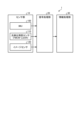
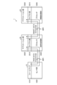
- FIG. 1 is a block diagram schematically showing a configuration example of a signal processing system according to an embodiment.
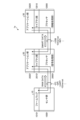
- FIG. 1 is a block diagram showing in more detail the configuration of an example of a signal processing system according to an embodiment.
- FIG. 1 is a block diagram showing the configuration of an example of a photodetection distance measurement sensor according to an embodiment.
- FIG. 2 is a schematic diagram schematically showing an example of a scanning pattern of a transmission optical signal according to an embodiment.
- FIG. 7 is a schematic diagram schematically showing another example of a scanning pattern of a transmitted optical signal.
- FIG. 7 is a schematic diagram schematically showing another example of a scanning pattern of a transmitted optical signal.
- FIG. 3 is a schematic diagram schematically showing a speed point group correction process according to the embodiment.
- FIG. 1 is a block diagram schematically showing a configuration example of a signal processing system according to an embodiment.
- FIG. 1 is a block diagram showing in more detail the configuration of an example of a signal processing system according to an
- FIG. 1 is a block diagram showing a hardware configuration of an example of a signal processing system applicable to the embodiment.
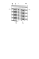
- FIG. 2 is a schematic diagram showing an example of a data format defined in MIPI-CSI-2 that is applicable to the embodiment.
- FIG. 2 is a schematic diagram showing another example of a data format defined in MIPI-CSI-2 that is applicable to the embodiment.
- FIG. 2 is a schematic diagram illustrating an example of transmitting a point cloud in a data format defined by MIPI-CSI-2, which is applicable to the embodiment.
- FIG. 2 is a schematic diagram showing an example in which Ethernet is applied as an interface for data transmission between each unit, which is applicable to the embodiment.
- FIG. 2 is a diagram illustrating an example of the architecture of a signal processing unit according to an embodiment.
- FIG. 2 is a flowchart of an example of a transmission optical signal detection process in a photodetection and ranging sensor that can be applied to the embodiment.
- FIG. FIG. 3 is a schematic diagram for explaining a transmission optical signal transmitted by an optical transmitter/receiver, which is applicable to the embodiment.
- FIG. 3 is a schematic diagram for explaining determination processing for a received optical signal according to an embodiment.
- FIG. 3 is a schematic diagram showing an example of data output when the photodetection and ranging sensor performs scanning according to a raster scanning pattern according to the embodiment.
- FIG. 2 is a schematic diagram for explaining a frame definition applicable to the embodiment.
- FIG. 3 is a schematic diagram for explaining the output timing of each data by the sensor unit according to the embodiment.
- FIG. 3 is a schematic diagram for explaining the output timing of each data by the sensor unit according to the embodiment.
- FIG. 2 is a schematic diagram showing an example of a data format of FMCW-LiDAR data and IMU data output from a sensor unit according to an embodiment.
- FIG. 2 is a schematic diagram showing an example of output data from the photodetection and ranging sensor according to the embodiment.
- FIG. 3 is a schematic diagram showing the definition of the coordinates of the injection point, which is applicable to the embodiment.
- FIG. 2 is a schematic diagram showing each emission point and an object as seen from a photodetection and ranging sensor.
- FIG. 3 is a schematic diagram showing the overall flow of processing related to point cloud correction in the signal processing unit according to the embodiment.
- FIG. 7 is a flowchart of an example showing processing related to point cloud correction in the signal processing unit according to the embodiment.
- 7 is a flowchart of an example showing correction processing of a velocity point group frame of a stationary body in the signal processing unit according to the embodiment.
- FIG. 3 is a schematic diagram for defining a coordinate system and each variable.
- FIG. 2 is a block diagram showing the configuration of an example of a signal processing system according to a first modification example of the implementation. It is a block diagram showing the composition of an example of the signal processing system concerning the 2nd modification of implementation.
- FIG. 1 is a block diagram schematically showing a configuration example of a signal processing system according to an embodiment.
- the signal processing system 1 includes a sensor section 10, a signal processing section 20, and an information processing section 30.
- the sensor section 10 includes an IMU (Inertial Measurement Unit) 100, a light detection distance measurement sensor 110, and an image sensor 120.
- the IMU 100 includes, for example, a 3-axis acceleration sensor, a 3-axis angular velocity sensor, and a 3-axis geomagnetic sensor, and outputs inertial measurement data (hereinafter referred to as IMU data as appropriate) from these sensors.
- the photodetection ranging sensor 110 is a sensor that measures distance using light, and in the embodiment, it is an FMCW-LiDAR (Frequency Modulated Continuous Wave-Laser Imaging Detection) that measures distance using a laser beam that is continuously modulated in frequency. and Ranging).
- the image sensor 120 is a so-called camera, and images a subject and outputs image data including, for example, information of R (red), G (green), and B (blue).
- the signal processing unit 20 is configured to process IMU data output from the IMU 100 of the sensor unit 10, FMCW-LiDAR data output from the photodetection and ranging sensor 110, and image data output from the image sensor 120. input.
- the signal processing unit 20 performs signal processing based on the input IMU data, FMCW-LiDAR data, and image data.
- the signal processing unit 20 generates information such as map information, velocity point groups of a stationary object and a moving object, motion meta information indicating the movement of the moving object, and image meta information regarding images in the region of interest by signal processing based on each data. do.
- the signal processing section 20 outputs each piece of generated information to the information processing section 30.
- the information processing section 30 performs predetermined processing according to each piece of information output from the signal processing section 20.
- the processing that the information processing section 30 performs in response to each piece of information output from the signal processing section 20 is not particularly limited.
- the information processing unit 30 may control the drive of the robot based on map information or the like.
- the information processing unit 30 may perform notification based on motion meta information or image meta information.
- the information processing section 30 may send instructions regarding signal processing to the signal processing section 20.
- the signal processing section 20 may control processing of the output of the sensor section 10 in accordance with this instruction. Further, the signal processing section 20 may control the operation of each sensor (IMU 100, light detection and ranging sensor 110, and image sensor 120) in the sensor section 10 according to this instruction.
- a general computer configuration including a central processing unit (Central Processing Unit), memory, storage device, etc. may be applied.
- the signal processing system 1 can output various data based on the measurement results by FMCW-LiDAR, and can make the measurement results by FMCW-LiDAR more versatile. .
- FIG. 2 is a block diagram showing in more detail the configuration of an example of the signal processing system 1 according to the embodiment.
- the sensor section 10 includes an IMU 100, a photodetection distance sensor 110 using FMCW-LiDAR, an image sensor 120, and a synchronization signal generation section 130.
- the synchronization signal generation unit 130 generates a synchronization signal.
- the synchronization signal may be a pulse with a predetermined period.
- the synchronization signal generation unit 130 supplies the generated synchronization signal to the IMU 100, the photodetection and ranging sensor 110, and the image sensor 120.
- the operation and data output timing of the IMU 100, the photodetection and ranging sensor 110, and the image sensor 120 are controlled in synchronization with the supplied synchronization signal, respectively.
- the IMU 100 includes a 3-axis acceleration sensor, a 3-axis angular velocity sensor, and a 3-axis geomagnetic sensor.
- the IMU 100 outputs sensor data from these three-axis acceleration sensors, three-axis angular velocity sensors, and three-axis geomagnetic sensors as IMU data.
- the IMU 100 may output IMU data with a time stamp indicating the time when the IMU data was acquired.
- the image sensor 120 is a so-called camera, and images a subject and outputs image data including, for example, R (red), G (green), and B (blue) information.
- the image sensor 120 includes a pixel array in which pixels that output pixel signals as electrical signals corresponding to received light are arranged in a matrix, and a drive circuit that drives each pixel of the pixel array.
- the image sensor 120 converts each pixel signal output as an analog signal from each pixel of the pixel array into digital pixel data and outputs the converted data.
- One frame of image data is composed of pixel data based on the output of each pixel included in the effective area of the pixel array.
- the sensor unit 10 includes an interface unit that controls data input and output of the IMU 100, the photodetection and ranging sensor 110, and the image sensor 120.
- the present invention is not limited to this, and the IMU 100, the photodetection and ranging sensor 110, and the image sensor 120 may each include separate interface sections.
- the photodetection distance sensor 110 is a sensor that measures distance using light, and in the embodiment, FMCW-LiDAR is applied.
- FMCW-LiDAR uses chirped light, in which the pulse frequency is changed linearly over time, as the emitted laser light.
- distance measurement is performed by coherent detection on a received signal that is a combination of part of the laser light emitted as chirp light, or local light synchronized therewith, and reflected light of the emitted laser light.
- FMCW-LiDAR With FMCW-LiDAR, by using the Doppler effect, it is possible to measure distance and velocity (Doppler velocity) at the same time. Therefore, by using FMCW-LiDAR, it becomes easy to quickly determine the position of objects with speed, such as people or other moving objects. Furthermore, since coherent detection is less susceptible to interference from other light sources, it is possible to avoid crosstalk, and furthermore, it is less affected by noise from high-intensity light sources such as sunlight. Furthermore, since FMCW-LiDAR is an active type, it is possible to perform measurements even in low-light environments such as darkness.
- the emission direction of the laser beam is scanned in the horizontal direction over a predetermined angle range, and further scanned in the vertical direction over a predetermined angle range, and the laser beam is emitted at each predetermined angle of the scan. Measurement is performed. Therefore, the measurement results by FMCW-LiDAR are obtained as point information for each scanning angle.
- the information on each measured point may include, as attribute information (attribute value), the distance based on the distance measurement result, the Doppler velocity, and the intensity of the received reflected light.
- the attribute information may include the intensity of each orthogonal polarization component of the reflected light.
- a set of points having three-dimensional or two-dimensional spatial coordinates is called a point group, and a point group in which each point includes velocity information (Doppler velocity) is called a velocity point group.
- the photodetection and ranging sensor 110 collects information indicating the distance, Doppler velocity, and intensity, a timestamp indicating the time when these information was acquired, and information indicating the emission direction of the laser beam (horizontal scanning angle, vertical scanning angle, etc.). ) and is output as FMCW-LiDAR data. That is, the FMCW-LiDAR data includes a velocity point cloud.
- FIG. 3 is a block diagram showing the configuration of an example of the photodetection and ranging sensor 110 according to the embodiment.
- the photodetection and ranging sensor 110 includes an optical scanning section 111, an optical transmitting/receiving section 112, a received signal processing section 113, an optical scanning control section 114, and a transmitting section 115.
- the optical transmitter/receiver 112 includes an optical transmitter that generates a transmit optical signal to be transmitted from the optical scanner 111 (described later), a transmit light controller that controls transmit light generated by the optical transmitter, and an optical scanner 111. an optical receiver that receives (receives) a received optical signal from the optical receiver.
- the optical transmitting unit includes, for example, a light source such as a laser diode for emitting laser light as transmission light, an optical system for emitting the light emitted by the light source, and driving the light source. and a laser output modulation device.
- the optical transmitter causes the light source to emit light in response to the optical transmission control signal supplied from the transmission light controller, and transmits a transmission optical signal using chirp light whose frequency changes linearly within a predetermined frequency range over time. eject.
- the transmitted optical signal is sent to the optical scanning section 111 and is also sent as local light to the optical receiving section.
- the transmission light control section In the optical transmission section, the transmission light control section generates a signal whose frequency changes linearly (increases and decreases) within a predetermined frequency range over time. Such a signal whose frequency changes linearly within a predetermined frequency range over time is called a chirp signal.
- the transmission light control section generates an optical transmission control signal, which is a modulation synchronization timing signal, which is input to the laser output modulation device included in the optical transmission section, based on this chirp signal.
- the transmission light control section generates an optical transmission control signal as a signal synchronized with the synchronization signal supplied from the synchronization signal generation section 130.
- the transmission light control section passes the generated optical transmission control signal to the optical transmission section and a received signal processing section 113, which will be described later.
- the optical receiving unit includes, for example, a light receiving unit that receives (receives) the received optical signal from the optical scanning unit 111, and a drive circuit that drives the light receiving unit.
- a configuration in which a condensing lens and a light receiving element such as a photodiode are combined can be applied to the light receiving section.
- the light receiving section further includes a light combining section that combines the received light received from the scanning section and the local light sent from the optical transmitting section.
- the received light is the reflected light of the transmitted light from the target object
- the received light will be a signal delayed from the local light according to the distance to the target, and the composite signal that combines the received light and the local light will be , a constant frequency signal (beat signal).
- the optical transmitting/receiving section 112 passes this signal to the received signal processing section 113 as a received waveform signal.
- the received signal processing unit 113 performs predetermined signal processing, such as fast Fourier transform, on the received signal passed from the optical transmitting/receiving unit 112 in synchronization with the synchronization signal supplied from the synchronization signal generation unit 130. Through this signal processing, the received signal processing unit 113 obtains the distance to the object, the Doppler velocity of the object, and the intensity of the received optical signal. The received signal processing unit 113 adds a timestamp generated in synchronization with a synchronization signal to the acquired distance, velocity, and Doppler velocity, and passes them to the transmitting unit 115.
- the time stamp here is a measurement-related time stamp indicating the timing at which the transmission optical signal was transmitted by the optical transmitter/receiver 112, and is generated and added for each measurement.
- the optical scanning control section 114 generates a scanning control signal for controlling the scanning of the transmitted optical signal in the optical scanning section 111. At this time, the optical scanning control section 114 generates a scanning control signal so that the scanning of the transmitted optical signal is synchronized with the synchronization signal supplied from the synchronization signal generation section 130.
- the optical scanning control section 114 may generate a scanning control signal for scanning a predetermined scanning range, or may generate a scanning control signal according to scanning control information transmitted from a control communication section 230, which will be described later. Good too.
- the optical scanning control unit 114 receives an angle detection signal indicating the scanning angle of the transmitted optical signal from the optical scanning unit 111.
- the optical scanning control unit 114 passes information indicating the scanning angle to the transmitting unit 115 based on the received angle detection signal.
- the optical scanning section 111 transmits the transmission optical signal sent from the optical transmission/reception section 112 at an angle according to a scanning pattern according to a scanning control signal supplied from the optical scanning control section 114, and also transmits the transmission optical signal sent from the optical transmission/reception section 112 at an angle according to a scanning pattern according to a scanning control signal supplied from the optical scanning control section 114. It receives light and outputs it as a received optical signal.
- a two-axis mirror scanning device for example, can be applied as a scanning mechanism for the transmitted optical signal.
- the scan control signal is, for example, a drive voltage signal applied to each axis of the two-axis mirror scanning device.
- the optical scanning unit 111 detects the horizontal and vertical angles at which the transmission optical signal is transmitted, and outputs an angle detection signal indicating the detected angle.
- the transmitting unit 115 sends the time stamp, distance, Doppler velocity, and intensity passed from the received signal processing unit 113 and the scanning angle passed from the optical scanning control unit 114 to the signal processing unit 20 as FMCW-LiDAR data.
- the FMCW-LiDAR data includes a time stamp for each measurement point in the photodetection and ranging sensor 110.
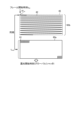
- FIG. 4 is a schematic diagram schematically showing an example of a scanning pattern of a transmitted optical signal according to the embodiment.
- FIG. 4 shows an example of a raster scan pattern among the scan patterns.
- the optical scanning unit 111 performs scanning within a predetermined angular range 45 according to the scanning line 40 that is folded back at both ends of the angular range 45 in the horizontal direction.
- the scanning line 40 corresponds to one locus scanned between the left end and the right end of the angular range 45.
- the optical scanning unit 111 scans between the upper end and the lower end of the angular range 45 according to the scanning line 40 in accordance with the scanning control signal.
- the optical scanning unit 111 sequentially and discretely changes the emission point 41 of the chirp light as the transmitted optical signal along the scanning line 40 at a constant time interval (point rate), for example, according to the scanning control signal.
- the injection point 41 within the angular range 45 constitutes one frame in FMCW-LiDAR.
- the scanning time from the upper end to the lower end of the angle range 45 is one frame time.
- the transmission optical signals at each emission point 41 are sequentially emitted at predetermined time intervals within one frame according to the scanning line 40. Therefore, the measurement data at each injection point 41 is acquired at different times for each injection point 41 according to the scanning order.
- the scanning speed by the two-axis mirror scanning device becomes slow. Therefore, the injection points 41 are not arranged in a grid in the angular range 45.
- the respective emission points 41 for example, at the emission points 41a and 41b (shown filled out) corresponding to the positions where the objects 50a and 50b exist, the emitted transmission optical signal is reflected by the objects 50a and 50b, and the reflected light is , which is returned as a received optical signal.
- the respective emission points 41 at the emission points 41 corresponding to positions where the objects 50a and 50b are not present, reflected light is not obtained and no received optical signal is obtained.
- the optical transmitter/receiver 112 may emit the transmission optical signal to one emitting point 41 one or more times. Further, the optical transmitter/receiver 112 emits a transmission optical signal using chirp light whose frequency changes continuously over time at each emission point 41, and the optical scanner 111 continuously changes the scanning angle. Therefore, the transmitted optical signal is irradiated onto the object in an elliptical shape along the scanning line 40, for example.
- the scanning pattern of the transmitted optical signal is not limited to the raster scanning pattern described above.
- 5A and 5B are schematic diagrams schematically showing another example of a scanning pattern of a transmitted optical signal.
- FIG. 5A shows an example of a multi-layer scanning pattern among the scanning patterns.
- multiple beams are rotated 360 degrees to simultaneously scan multiple lines. More specifically, in multi-layer scanning, the emission point 41 of the transmitted optical signal is sequentially moved at regular time intervals along the scanning lines 42 1 , 42 2 , ..., 42 N of each of the plurality of beams. , vary discretely. In multi-layer scanning, the scanning lines 42 1 , 42 2 , .
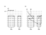
- FIG. 5B shows an example of a dot scanning type scanning pattern among the scanning patterns.
- the beam scanning trajectory is fixed at each injection point 41 and is therefore discrete rather than continuous.
- a transmitted optical signal is emitted, and after the reception of the reflected optical signal is completed, the beam is switched to the next emission point 41.
- section (a) shows an example in which beam switching is performed sequentially according to a prescribed sequence, as indicated by an arrow 47 in the figure.
- section (b) shows an example in which beam switching is performed in an arbitrary order, for example, by scanning control settings from the signal processing unit 20, as indicated by an arrow 48 in the figure.
- a predetermined region of the entire scanning region may be scanned by scanning control settings, or a plurality of predetermined regions may be set within one frame. Furthermore, the predetermined area may be determined based on the detected position of a moving object or a stationary object.
- each component included in the signal processing unit 20 includes a part (referred to as a library part) that provides individual functions, and a part that uses the functions provided by the part to perform the desired processing. It can be roughly divided into two parts (referred to as application parts).
- the library section includes, for example, a receiving section 200, a sensor position and orientation estimation section 210, a moving object/stationary object separation section 211, a sensor speed estimation section 212, a stationary object point group correction section 213, and a moving object point group.
- a correction unit 214 is included.
- the application section includes, for example, a map conversion section 220, a moving object state estimation section 221, a 3D/2D conversion section 222, a ROI (Region of Interest) extraction section 223, a synthesis section 224, a motion recognition section 225, An image recognition unit 226 is included.
- the configurations included in the library unit and the application unit are not limited to the above-mentioned example.
- the moving body state estimating unit 221, or the moving body state estimating unit 221 and the 3D/2D converting unit 222 may be included in the library unit.
- the transmitting unit 201 may be included in either the library unit or the application unit, or may be included in neither.
- the receiving section 200 may also be included in the application section, either the library section or the application section, or it may be included in neither.
- the receiving section 200 receives each data output from the sensor section 10 and passes the received data to each section of the signal processing section 20. More specifically, the receiving unit 200 passes the IMU data output from the IMU 100 of the sensor unit 10 to the sensor position and orientation estimation unit 210. The receiving unit 200 also passes the FMCW-LiDAR data output from the photodetection and ranging sensor 110 of the sensor unit 10 to the moving object/stationary object separation unit 211. Furthermore, the receiving unit 200 passes the image data output from the image sensor 120 of the sensor unit 10 to the ROI extracting unit 223.
- the receiving unit 200 functions as a receiving unit that receives velocity point group data including a plurality of points each having velocity information and time information.
- the sensor position and orientation estimation unit 210 estimates the position, orientation, and angular velocity of the IMU 100 based on the IMU data passed from the reception unit 200. For example, the sensor position and orientation estimation unit 210 performs sensor fusion processing such as a Kalman filter using sensor data from a 3-axis acceleration sensor, a 3-axis angular velocity sensor, and a 3-axis geomagnetic sensor included in the IMU data. By doing so, the current position, attitude, and angular velocity of the IMU 100 are estimated.
- sensor fusion processing such as a Kalman filter using sensor data from a 3-axis acceleration sensor, a 3-axis angular velocity sensor, and a 3-axis geomagnetic sensor included in the IMU data.
- the sensor position and orientation estimating unit 210 acquires calibration data such as the positional relationship of the reference coordinate system of the photodetection and ranging sensor 110 with respect to the reference coordinate system of the IMU 100 and the internal parameters of each sensor in advance, and uses the data at the time of estimation.
- the sensor position and orientation estimation unit 210 passes data on the estimated sensor position, orientation, and angular velocity to the sensor velocity estimation unit 212, the map conversion unit 220, and the transmission unit 201.
- the moving object/stationary object separation section 211 receives FMCW-LiDAR data from the receiving section 200, and also receives a sensor speed indicating the speed of the photodetection and ranging sensor 110 estimated by a sensor speed estimating section 212, which will be described later.
- the moving object/stationary object separation unit 211 performs speed discrimination based on the Doppler speed included in the passed FMCW-LiDAR data and the sensor speed, and separates the speed point group indicated by the FMCW-LiDAR data from the speed point group due to the moving object. It is separated into a velocity point group due to a stationary body.
- the moving object/stationary object separation unit 211 may extract a moving object velocity point group and a stationary object velocity point group from the FMCW-LiDAR data corresponding to one frame of scanning.
- the moving object/stationary object separation unit 211 subtracts the optical axis direction component of the sensor speed from the Doppler velocity of each measurement point included in the FMCW-LiDAR data, and calculates the influence of the movement of the sensor unit 10 from the speed information of the speed point group. Then, calculate the corrected Doppler velocity of each measurement point as seen from the stationary body's coordinate system. That is, the corrected Doppler velocity is the Doppler velocity included in the FMCW-LiDAR data, excluding the influence of the movement of the sensor unit 10.
- the moving object/stationary object separation unit 211 performs a threshold value judgment on the magnitude of this corrected Doppler velocity, and selects a certain spatial range (corresponding to the size of the target object) among the measurement points whose magnitude is equal to or greater than the threshold value.
- a velocity point group based on localized measurement points (referred to as a localized velocity point group) is extracted as a moving body velocity point group.
- the moving object/stationary object separation unit 211 may extract a plurality of moving object velocity point groups from one frame of FMCW-LiDAR data.
- the moving object/stationary object separation unit 211 performs a threshold value determination on the magnitude of the corrected Doppler velocity for the measurement points based on the FMCW-LiDAR data. As a result of this threshold value determination, the moving object/stationary object separation unit 211 extracts a set of measurement points whose corrected Doppler velocity is equal to or less than the threshold value as a stationary object velocity point group.
- the moving object/stationary object separation unit 211 may provide two types of threshold values, a threshold value v tha and a threshold value v thb ( ⁇ v tha ), in this threshold determination.
- the moving object/stationary object separation unit 211 may extract measurement points whose corrected Doppler velocities are equal to or greater than a threshold value v tha as a moving object velocity point group, and measurement points whose corrected Doppler velocity is equal to or less than a threshold value v thb as a stationary object velocity point group. This means that there is an intermediate point group that does not belong to either the moving body velocity point group or the stationary body velocity point group. For the purpose of extracting measurement points that are clearly stationary, it is appropriate to provide two types of threshold values in this way.
- a point cloud frame is composed of a velocity point group obtained from one frame of FMCW-LiDAR data.
- the moving body/stationary body separation unit 211 passes the extracted stationary body velocity point group to the sensor velocity estimation unit 212 and the stationary body point group correction unit 213. Further, the moving object/stationary object separation section 211 passes the extracted moving object velocity point group to the moving object point group correction section 214 .
- the sensor speed estimation unit 212 estimates the speed of the sensor unit 10 based on the stationary body point group passed from the moving body/stationary body separation unit 211 and the sensor position, attitude, and angular velocity passed from the sensor position and posture estimation unit 210. Estimate the sensor speed that indicates. A specific example of the sensor speed estimation process by the sensor speed estimator 212 will be described later.
- the sensor speed estimation unit 212 passes the estimated sensor speed to the stationary body point group correction unit 213 and the moving body/stationary body separation unit 211 , and inputs it to the moving body/stationary body separation unit 211 . Further, the sensor speed estimating unit 212 passes the estimated sensor speed to the transmitting unit 201.
- the stationary body point cloud correction unit 213 corrects the stationary body velocity point group using the sensor position, orientation, and angular velocity passed from the sensor position and posture estimation unit 210 and the sensor velocity passed from the sensor velocity estimation unit 212. I do.
- the moving body point cloud correction unit 214 receives the sensor position, orientation, and angular velocity passed from the sensor position and orientation estimation unit 210, the sensor velocity passed from the sensor velocity estimation unit 212, and the sensor velocity passed from the moving body state estimation unit 221, which will be described later.
- the moving object velocity point group is corrected using information indicating the state of the moving object.
- the acquisition time of measurement data at each measurement point within a frame varies depending on the type of scanning pattern and the position of the measurement point within the frame.
- the stationary body point cloud correction unit 213 and the moving body point cloud correction unit 214 estimate the data of each point when each point of the velocity point group in the frame is acquired at the same predetermined time, and adjust the velocity according to the estimation result. Correct the point cloud.
- FIG. 6 is a schematic diagram schematically showing a speed point group correction process according to the embodiment.
- section (a) shows an example of the output timing of FMCW-LiDAR data output from the photodetection and ranging sensor 110.
- FMCW-LiDAR data is output at regular time intervals from frame start time t fst1 to next frame start time t fst2 .
- Each point of the velocity point group based on FMCW-LiDAR data has time information corresponding to the output timing of each data.
- the data corresponding to the injection point 41 corresponding to the position where the objects 50a, 50b (see FIG. 4), etc. are present is shown by a solid line (with diagonal lines). Further, data corresponding to the injection point 41 corresponding to a position where objects 50a, 50b, etc. are not present is shown by a dotted line. The data indicated by the dotted line indicates that no object is actually detected from the received optical signal.
- section (b) schematically shows the state in which the FMCW-LiDAR data output from the photodetection and ranging sensor 110 is corrected by the stationary object point cloud correction section 213 and the moving object point cloud correction section 214.
- the stationary body point cloud correction unit 213 and the moving body point cloud correction unit 214 calculate each FMCW-LiDAR data from frame start time t fst1 to frame start time t fst2 based on the sensor position, orientation, angular velocity, and sensor velocity, for example.
- a value at a reference time for correction, for example, the frame start time tfst2 is estimated.
- the stationary body point group correction unit 213 and the moving body point group correction unit 214 respectively correct the stationary body velocity point group and the moving body velocity point group based on the estimation results.
- the stationary body point group correction unit 213 and the moving body point group correction unit 214 correct the time information of each point included in the stationary body velocity point group and the moving body velocity point group to the reference time. This eliminates distortion of the point cloud caused by self-motion or moving body motion within the frame time, and in the embodiment, the measurement results by FMCW-LiDAR can be used more generally.
- the stationary body point group correction unit 213 and the moving body point group correction unit 214 output corrected stationary body velocity point groups and moving body velocity point groups, respectively.
- the stationary body point group correction unit 213 and the moving body point group correction unit 214 calculate the correction reference time (in the example of FIG. 6, the frame start A timestamp indicating the time t fst2 ) is added and output.
- the timestamp here is a value for each frame.
- the stationary body point cloud correction unit 213 and the moving body point cloud correction unit 214 correct at least one attribute value regarding at least one point included in the velocity point cloud data based on the estimated value at a predetermined time. function as a department.
- the stationary body point group correction unit 213 and the moving body point group correction unit 214 respectively pass the corrected stationary body velocity point group and the moving body velocity point group to the transmitting unit 201.
- each point included in the stationary body velocity point group and the moving body velocity point group within one frame can be treated as points acquired at the same time, and the stationary body velocity points in the subsequent stage can be treated as points included in the stationary body velocity point group and the moving body velocity point group in one frame. It becomes possible to reduce the processing load on the group and the moving body velocity point group.
- the velocity point group is corrected based on values estimated based on the sensor position, orientation, and angular velocity, and the sensor velocity. Therefore, in the embodiment, a velocity point group in which each point has time information of the same time can be obtained using one frame of FMCW-LiDAR data.
- the method of acquiring a velocity point group in which each point has time information of the same time is not limited to the above method.
- the stationary body point cloud correction unit 213 passes the corrected stationary body velocity point group to the transmission unit 201 and the map conversion unit 220.
- the map conversion unit 220 estimates and generates map information based on the sensor position, orientation, and angular velocity passed from the sensor position and orientation estimation unit 210 and the stationary body velocity point group passed from the stationary body point cloud correction unit 213. do.
- the map information includes the self-location of the sensor unit 10 and a map of the surrounding environment of the sensor unit 10.
- the map conversion unit 220 may apply SLAM (Simultaneous Localization and Mapping) technology to map creation.
- the map converter 220 passes the generated map information to the transmitter 201.
- the moving object point cloud correction section 214 passes the corrected moving object velocity point group to the transmitting section 201 and also to the moving object state estimation section 221 and the combining section 224.
- the moving object state estimation unit 221 separates each moving object included in one frame, for example, based on the corrected moving object speed point group.
- the moving object state estimation unit 221 estimates the state of each separated moving object, including the position, orientation, speed, and angle of the moving object, based on the corresponding moving object velocity point group.
- the moving object state estimation section 221 passes moving object state information indicating the estimated state of the moving object to the transmitting section 201 and also to the moving object point group correction section 214 and the 3D/2D conversion section 222.
- the 3D/2D conversion unit 222 converts the moving body velocity point group, which is 3D (Three-Dimensional) information, into 2D (Two-Dimensional) data corresponding to image data output from the image sensor 120. More specifically, the 3D/2D conversion unit 222 converts the 3D coordinates of the moving body velocity point group into 2D coordinates based on the coordinate system of image data by the image sensor 120. The 3D/2D conversion unit 222 acquires calibration data such as the positional relationship of the reference coordinate system of the light detection and ranging sensor 110 with respect to the reference coordinate system of the image sensor 120 and the internal parameters of each sensor in advance, and uses the data at the time of conversion. do.
- the 3D/2D conversion unit 222 passes the point group whose coordinates of the moving body velocity point group have been converted into 2D coordinates to the ROI extraction unit 223.
- the ROI extraction unit 223 extracts a region of interest (ROI) from the image data passed from the image sensor 120 via the reception unit 200, based on the point group based on 2D coordinates passed from the 3D/2D conversion unit 222. More specifically, the ROI extraction unit 223 may extract, for example, a region corresponding to a point group based on 2D coordinates passed from the 3D/2D conversion unit 222 in the image data as a region of interest. Note that if the positional relationship between the photodetection and ranging sensor 110 and the image sensor 120 is known, the ROI extraction unit 223 can instantaneously calculate the correspondence between the image data and the point cloud based on 2D coordinates. It is.
- ROI region of interest
- the ROI extraction unit 223 passes the extracted image data of the region of interest to the transmission unit 201 and also to the synthesis unit 224 and the image recognition unit 226.
- the synthesis unit 224 synthesizes the moving body velocity point group passed from the moving body point group correction unit 214 and the image data of the region of interest passed from the ROI extraction unit 223.
- the synthesizing unit 224 may synthesize the moving body velocity point group with the image data of the region of interest.
- the synthesizing unit 224 may associate velocity information of each point included in the moving body velocity point group with each pixel data in the image data of the region of interest. This image obtained by combining speed information with respect to each pixel of the image data of the region of interest is called a composite image.
- the composition unit 224 is not limited to this, and the composition unit 224 may compose the image data of the region of interest with the moving body velocity point group.
- the synthesizing unit 224 may associate each point of the moving body velocity point group with corresponding pixel data information in the region of interest.
- a point group obtained by combining each pixel data of the region of interest with each point of the moving body velocity point group is called a composite point group.
- the composition unit 224 passes the composite image or composite point group to the transmission unit 201 and also to the motion recognition unit 225.
- the motion recognition unit 225 recognizes the motion of the moving object based on the composite image or composite point group passed from the composition unit 224.
- the motion recognition unit 225 can acquire velocity distribution information based on velocity information of each point included in the composite image or composite point group. By using this velocity distribution information, the motion recognition unit 225 can estimate the motion of the moving object more precisely.
- the motion recognition unit 225 may perform motion recognition using a learning model trained by machine learning based on known velocity distribution information.
- the motion recognition unit 225 recognizes the motion of a moving object and outputs meta information regarding the motion (walking, running, etc.).
- the motion meta information output from the motion recognition section 225 is passed to the transmission section 201.
- the image recognition unit 226 performs image recognition based on the image data of the region of interest passed from the ROI extraction unit 223, and outputs image meta information (person, Mr. ⁇ , vehicle, etc.). .
- the image recognition unit 226 may perform image recognition using a learning model that has been trained by machine learning based on image data of known images.
- the image meta information output from the image recognition unit 226 is passed to the transmission unit 201.
- the transmitter 201 transmits the sensor position, orientation, and angular velocity passed from the sensor position and orientation estimation unit 210 and the sensor velocity passed from the sensor velocity estimation unit 212 to the information processing unit 30. Further, the transmitting unit 201 transmits the map information passed from the map conversion unit 220 and the corrected stationary body velocity point group passed from the stationary body point cloud correction unit 213 to the information processing unit 30. Further, the transmitting unit 201 transmits the moving body velocity point group passed from the moving body point group correction unit 214 and the moving body state information passed from the moving body state estimation unit 221 to the information processing unit 30.
- the transmitting unit 201 receives the composite image or composite point group passed from the composition unit 224, the ROI image passed from the ROI extraction unit 223, the motion meta information passed from the motion recognition unit 225, and the image recognition unit 201.
- the image meta information passed from the section 226 is transmitted to the information processing section 30.
- the transmitting unit 201 adds a time stamp to each of the above-mentioned information and point clouds and transmits them to the information processing unit 30 .
- the time stamp that the transmitting unit 201 adds to each information and point group may be time information in units of one frame of scanning by the photodetection and ranging sensor 110.
- information indicating the frame start time t fst2 may be added as a timestamp.
- the transmitting unit 201 functions as a transmitting unit that adds corrected time information indicating a predetermined time to the attribute value corrected by the correcting unit and transmits the attribute value.
- the transmitting section 201 may selectively transmit information and point clouds to the information processing section 30 in response to a request from the information processing section 30. Further, the transmitting unit 201 may transmit each of the above-mentioned information and point clouds to a different destination than the information processing unit 30.
- FIG. 7 is a block diagram showing the hardware configuration of an example of the signal processing system 1 applicable to the embodiment.
- the sensor unit 10 includes a sensor group 1000 and firmware 1010.
- Sensor group 1000 includes IMU 100 , photodetection and ranging sensor 110 , and image sensor 120 .
- the firmware 1010 may be a program for controlling the operation of the sensor group 1000.
- the firmware 1010 may control, for example, an interface (not shown) as hardware that controls data input/output of each sensor included in the sensor group 1000 or the operation of the synchronization signal generation unit 130.
- the interface may include a memory in which firmware 1010 is stored in advance, and a processor that operates according to the firmware 1010 stored in the memory.
- the signal processing section 20 includes a processor 2000, and the above-mentioned library section 2010 and application section 2020 are configured by the processor 2000 operating according to a program stored in a memory (not shown).
- the processor 2000 may be, for example, an ISP (Image Signal Processor).
- the processor 2000 is not limited to this, and may be a DSP (Digital Signal Processor) or a CPU (Central Processing Unit).
- the configuration is not limited to this, and it is also possible to configure some or all of the units included in the library unit 2010 and the application unit 2020 described above using hardware circuits that operate in cooperation with each other.
- the information processing unit 30 includes a processor 3000 provided by, for example, an ISP, and a library unit 3010 and an application unit 3020 are configured by the processor 3000 operating according to a program stored in a memory (not shown).
- the library section 3010 is a collection of programs that provide individual functions in the information processing section 30, and the application section 3020 is a collection of programs that execute target processing using the functions provided by the library section 3010. .
- the library unit 3010 may include a function of outputting a control command for driving the robot.
- the application section 3020 may include a function of determining the robot's motion based on the map information, motion meta information, image meta information, etc. passed from the signal processing section 20.
- the library unit 3010 may include a function of outputting a control command for controlling the operation of the surveillance camera.
- the application unit 3020 may include a function of making a judgment based on an image from a surveillance camera, motion meta information passed from the signal processing unit 20, image meta information, and the like.
- the configuration is not limited to this, but it is also possible to configure part or all of the units included in the library unit 3010 and the application unit 3020 by hardware circuits that operate in cooperation with each other. Further, the information processing section 30 may be a general computer.
- the output of each sensor included in the sensor group 1000 (image data, FMCW-LiDAR data, IMU data) is output as RAW data in a predetermined format under the control of the firmware 1010, and is output by an interface (not shown).
- the signal is transmitted to the signal processing section 20.
- the signal processing unit 20 receives the RAW data transmitted from the sensor unit 10 using the receiving unit 200 and passes it to the library unit 2021.
- the library unit 2010 performs the above-described processing on the RAW data passed from the receiving unit 200 and passes the processed data to the application unit 2020.
- the application unit 2020 performs the above-described processing on the data passed from the library unit 2010, and the transmission unit 201 adds a frame-based time stamp to each piece of information and point cloud generated by this processing. Output. In the example of FIG. 7, the output of the signal processing section 20 is transmitted to the information processing section 30 as SMART data.
- the information processing unit 30 receives the SMART data transmitted from the signal processing unit 20 and passes it to the library unit 3010.
- the library unit 3010 performs processing related to individual functions on the passed SMART data and passes it to the application unit 3020.
- the application unit 3020 performs predetermined processing on the data passed from the library unit 3010 and generates output data.
- the data generated by the application unit 3020 may be output from the information processing unit 30, for example.
- the information processing unit 30 may generate a request to the signal processing unit 20 using, for example, the application unit 3020 and transmit the generated request to the signal processing unit 20.
- the application unit 3020 may generate and transmit to the signal processing unit 20 a request specifying each piece of information that can be transmitted by the signal processing unit 20 by the transmitting unit 201, necessary information from the point cloud, and the point cloud. .
- the signal processing unit 20 may generate a request to the sensor unit 10 using, for example, the application unit 2020, and may transmit the generated request to the sensor unit 10.
- the application unit 2020 may generate and transmit a request to the photodetection and ranging sensor 110 to limit the scanning range to the region of interest.
- MIPI Mobile Industry Processor Interface
- MIPI-CSI Cara Serial Interface-2
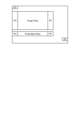
- FIG. 8 is a schematic diagram showing an example of a data format defined in MIPI-CSI-2 that is applicable to the embodiment.
- FIG. 8 shows an example of transmitting one frame of image data.
- a case of data transmission from the sensor section 10 to the signal processing section 20 will be described.
- the upper left of the diagram is the start position of data transmission, and data is transmitted in order from left to right on the diagram, and further in order from top to bottom on the diagram. .
- a field FS Frarame Start
- a field FE Fre End
- Data transmission starts from the leftmost data, and data transmission for that row sequentially progresses toward the rightmost data.
- data transmission starts again sequentially from the left end data toward the right end one row lower in the figure.
- blank areas indicate that there is no data to be transmitted.
- the field PH is a field in which a packet header is transmitted
- the field PF is a field in which a packet footer is transmitted.
- the field Image Data is a field to which image data is transmitted.
- the image data of the field Image Data is sandwiched between the field PH and the field PF for each row, and is sequentially transmitted from the left side to the right side. Image data output from the image sensor 120 may be transmitted using this field Image Data.
- the field Embedded Data is a field for transmitting data other than image data. For example, if optional data is defined, the data is generally sent in the field Embedded Data.
- the data of the field Embedded Data is sandwiched between the field PH and the field PF and is transmitted sequentially from the left side to the right side, similarly to the image data.
- IMU data output from the IMU 100 of the sensor unit 10 may be transmitted using this field Embedded Data.
- Information indicating the type of data (IMU data, etc.) transmitted by the field Embedded Data may be transmitted by the field PH.
- FIG. 9 is a schematic diagram showing another example of a data format defined in MIPI-CSI-2 that is applicable to the embodiment.
- section (a) is an example in which the field Embedded Data is transmitted after the field Image Data, similar to FIG. 8.
- Section (b) is an example in which the transmission of the field Image Data is temporarily interrupted and the field Embedded Data is transmitted in the middle of the field Image Data.
- section (c) is an example in which the field Embedded Data is transmitted before and after the field Image Data.
- the field Embedded Data may be transmitted before the field Image Data.
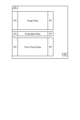
- FIG. 10 is a schematic diagram showing an example of transmitting a point cloud in a data format defined by MIPI-CSI-2, which is applicable to the embodiment.
- field Embedded Data is similarly transmitted between fields PH and PF.
- IMU data is transmitted in the field Embedded Data.
- point cloud data is transmitted by the field Point Cloud Data, which is sandwiched between fields PH and PF.
- a field FE indicating the end of the frame is transmitted.
- the field Image Data, the field Embedded Data, and the field Point Cloud Data are transmitted in this order, but the order in which each data is transmitted is not limited to this example. Furthermore, the field Image Data and the field Point Cloud Data may be divided and transmitted within one frame.
- the interface for data transmission between the sensor section 10 and the signal processing section 20 and between the signal processing section 20 and the information processing section 30 is MIPI, but this is not limited to this example.
- other interfaces may be applied as interfaces related to these data transmissions.
- a serial interface mainly used for internal data communication of a device such as a receiver/transmitter
- a communication interface such as a USB (Universal Serial Bus), or an Ethernet (registered trademark)
- an interface mainly used for external communication of devices such as USB, Ethernet, or Wi-Fi (Wireless Fidelity) (registered trademark) may be applied between the signal processing unit 20a and the information processing unit 30.
- Wi-Fi Wireless Fidelity
- FIG. 12 is a diagram showing an example of the architecture of the signal processing unit 20 according to the embodiment.
- the signal processing unit 20 has a structure in which an OS (Operating System) 2030 operates on a processor 2000 such as a hardware such as an ISP, and a library unit 2010 and an application unit 2020 operate on the OS 2030.
- OS Operating System
- the application section 2020 includes an API (Application Programming Interface) calling section 2040
- the library section 2010 includes an API processing section 2041.
- the API calling unit 2040 in accordance with a request from the application unit 2020, calls a function of the library unit 2010 according to the request.
- the API processing unit 2041 returns a response by the function in the library unit 2010 to the API calling unit 2040 in response to the function calling by the API calling unit 2040.
- the API calling unit 2040 requests the library unit 2010 for a moving body velocity point group.
- the API processing unit 2041 calls the function of the moving object point cloud correction unit 214 in response to this request, and returns the moving object velocity point cloud output from the moving object point cloud correction unit 214 to the API calling unit 2040.
- the API calling unit 2040 passes the moving body velocity point group returned from the API processing unit 2041 to the moving body state estimation unit 221.
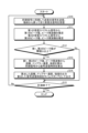
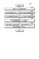
- FIG. 13 is a flowchart of an example of a transmission optical signal detection process in the photodetection and ranging sensor 110, which is applicable to the embodiment.
- step S10 the light detection and ranging sensor 110 transmits (emits) a transmission optical signal using a laser beam whose frequency is continuously modulated in synchronization with the synchronization signal by the optical transmitting/receiving unit 112, and the received light is reflected from the object and returned. Receive a signal.
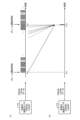
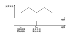
- FIG. 14 is a schematic diagram for explaining a transmission optical signal transmitted by the optical transceiver 112, which is applicable to the embodiment.
- the upper diagram in FIG. 14 shows the relationship between the optical frequency of the transmitted optical signal and time, and the lower diagram shows the signal transmission start time t st in the upper diagram.
- the vertical axis represents the optical frequency of the transmitted optical signal
- the horizontal axis represents time.
- the optical transmitter/receiver 112 linearly increases and decreases the optical frequency of the laser beam, for example, from a signal transmission start time t st1 to a next signal transmission start time t st2 , and generates chirp light. do.
- the optical transmitting/receiving section 112 emits the chirp light resulting from the combination of rising and falling optical frequencies as a transmission optical signal from the optical scanning section 111 toward a predetermined emission point.
- chirp light is generated by linearly increasing and decreasing the optical frequency of the transmitted optical signal according to the above-mentioned period, and is emitted from the optical scanning unit 111 as a transmitted optical signal.
- the transmitted optical signal is thus formed by chirped light with a set of rising and falling optical frequencies that are transmitted successively.
- the light detection and ranging sensor 110 uses the received signal processing unit 113 to calculate a first peak value and a first peak value from the first received spectrum signal in the received received optical signal. Estimate the signal spectrum frequency (peak frequency) at the peak value. Further, the light detection and ranging sensor 110 uses the received signal processing unit 113 to calculate a second peak value and a signal spectrum frequency (peak frequency) at the peak value from the second received spectrum signal in the received received optical signal. presume.
- the first received spectrum signal is a signal corresponding to a transmitted optical signal in a period in which the optical frequency increases among the received optical signals.
- the second received spectrum signal is a signal corresponding to the transmitted optical signal in a period in which the optical frequency decreases among the received optical signals.
- the photodetection and ranging sensor 110 determines in the received signal processing unit 113 whether the first peak value and the second peak value estimated in step S11 are greater than or equal to the threshold th.
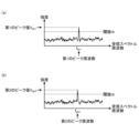
- FIG. 15 is a schematic diagram for explaining determination processing for received optical signals according to the embodiment.
- section (a) is a diagram showing determination processing for the first received spectrum signal
- section (b) is a diagram showing determination processing for the second received spectrum signal.
- the vertical axis shows the intensity of the received optical signal
- the horizontal axis shows the received spectrum frequency.
- the intensity of the first received spectrum signal exceeds the threshold th at the signal spectrum frequency f pk1 and the first peak value V pk1 is obtained.
- the signal spectrum frequency f pk1 at which the intensity of the first received spectrum signal takes the first peak value V pk1 is defined as the first peak frequency.
- the intensity of the second received spectrum signal exceeds the threshold th at the signal spectrum frequency f pk2 , and the second peak value V pk2 is obtained.
- the signal spectrum frequency f pk2 at which the intensity of the second received spectrum signal takes the second peak value V pk2 is defined as the second peak frequency.
- step S12 determines that at least one of the first peak value V pk1 and the second peak value V pk2 is less than the threshold th (step S12, "No"), the process moves to step S15.
- the received signal processing unit 113 determines that the first peak value V pk1 and the second peak value V pk2 are each greater than or equal to the threshold th (step S12, "Yes"), the process proceeds to step S13.
- step S13 the received signal processing unit 113 selects the first peak value V pk1 and the second peak value V pk2 , and the signal spectrum frequency f pk1 that takes the first peak value V pk1 and the second peak value V pk2 . and f pk2 , the distance to the object, the Doppler velocity with respect to the object, and the intensity of the received optical signal are calculated. Furthermore, the received signal processing unit 113 calculates the signal transmission start time t st1 based on the synchronization signal.
- the emission point 41 corresponding to the received optical signal in which the first peak value V pk1 and the second peak value V pk2 are each greater than or equal to the threshold value th is defined as the detection point where the object is detected.
- the received signal processing unit 113 outputs the distance, Doppler velocity, and intensity calculated in step S13. Further, the received signal processing unit 113 outputs the signal transmission start time calculated in step S13 as a timestamp for each measurement (for each injection point).
- the transmitter 115 receives the distance, Doppler velocity and intensity output from the received signal processor 113, and the time stamp.
- the transmitter 115 adds a time stamp to the received distance, Doppler velocity, and intensity, and outputs them as FMCW-LiDAR data from the photodetection and ranging sensor 110.
- the photodetection distance measurement sensor 110 determines whether the measurement has ended. For example, the photodetection and distance measurement sensor 110 may determine whether the measurement has been completed according to a control signal (not shown) input to the sensor unit 10 from the outside. When the photodetection and ranging sensor 110 determines that the measurement has ended, it ends the series of processes according to the flowchart of FIG. 14 .
- step S15 determines in step S15 that the measurement has not been completed. If the photodetection distance measurement sensor 110 determines in step S15 that the measurement has not been completed, the process returns to step S10 and executes the process for the next injection point.
- step S12 in the flowchart of FIG. 13 will be explained using a specific example.
- FIG. 16 is a schematic diagram showing an example of data output when the photodetection and ranging sensor 110 scans in a raster scanning pattern according to the embodiment.
- section (a) corresponds to FIG. 4 described above, in which the vertical axis indicates the vertical angle of scanning, and the horizontal axis indicates the horizontal angle of scanning.
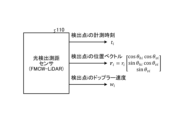
- Section (b) shows an example in which FMCW-LiDAR data output from the photodetection and ranging sensor 110 corresponding to each emission point 41 is arranged in time series.
- the emission points 41a and 41b shown filled in in the figure are emission points corresponding to the positions where the objects 50a and 50b (see FIG. 4) exist, for example, and the reflected light reflected by the objects 50a and 50b is received. It is returned as an optical signal.
- the light detection and ranging sensor 110 scans between the upper end and the lower end of the angular range 45 within a predetermined angular range 45 by the optical scanning unit 111, following the scanning line 40 that is folded back at both ends of the angular range 45 in the horizontal direction. .
- Each injection point 41, 41a and 41b within this angular range 45 constitutes a point cloud frame.
- the output data of each emission point 41 is output at predetermined time intervals, for example, according to the emission timing of the transmission optical signal.
- the light detection and ranging sensor 110 receives the transmitted optical signal. Either the corresponding received optical signal is not received, or it can be assumed that the received received optical signal is noise.
- step S12 the process moves to step S13.
- step S12 the process moves to step S15.
- the processes of steps S13 and S14 in the flowchart of FIG. 13 are executed at the emission points 41a and 41b corresponding to the positions where the objects 50a and 50b are present.
- the processes of step S13 and step S14 are canceled, and the next injection point Processing for is executed.
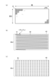
- FIG. 17 is a schematic diagram for explaining frame definitions applicable to the embodiment.
- section (a) shows an example of a frame based on image data output from the image sensor 120.
- Sections (b) and (c) in FIG. 17 each show examples of frames based on FMCW-LiDAR data output from the photodetection and ranging sensor 110.
- section (b) shows an example of a raster scan pattern by raster scan
- section (c) shows an example of a dot scan pattern by dot scan.
- Raster scanning is realized, for example, by a mechanical mirror scanner. Further, dot scanning is realized by a beam steering device such as an OPA (Optical Phase Array) or a light beam switching element.
- OPA Optical Phase Array
- a frame 60a is composed of a set of pixels 61 including information of each color of R (red), G (green), and B (blue).
- the size of the frame 60a is expressed by the number of pixels 61 in the width direction and height direction.
- Each pixel 61 is arranged in a matrix, corresponding to each pixel included in the effective pixel area of the pixel array.
- a frame (point cloud frame) 60b is composed of the injection points 41 within a predetermined angular range 45.
- scanning is performed according to the scanning lines 40 that are folded back at both ends of the angular range 45 in the horizontal direction.
- the position of each emission point 41 on the scanning line 40 is represented by the horizontal and vertical scanning angles (horizontal angle ⁇ hi , vertical angle ⁇ vi ) of the optical signal transmitted by the optical scanning unit 111.
- a transmission optical signal is formed by continuously transmitting chirp light with a set of increasing and decreasing optical frequencies.
- Each emission point 41 shown in section ( b ) of FIG. 17 has a scanning angle (horizontal angle ⁇ h i , vertical angle ⁇ v i ).
- each injection point 43 within a predetermined scanning range 46 constitutes a frame (point group frame) 60c.
- each emission point 43 completes the chirp light. That is, a transmission optical signal is transmitted for each emission point 43. Therefore, the position of each injection point 43 may be represented by xy coordinates within the scanning range 46.
- FIGS. 18A and 18B are schematic diagrams for explaining the output timing of each data by the sensor unit 10 according to the embodiment.
- the image sensor 120 is exposed using a global shutter method in which all pixels are exposed simultaneously.
- FIG. 18A shows an example of measurement timing by each sensor of the sensor unit 10 according to the embodiment.
- the IMU 100, the photodetection distance sensor 110, and the image sensor 120 each perform a measurement operation in synchronization with a synchronization signal Sync supplied from the synchronization signal generation unit 130, and output data. It is assumed that the synchronization signal Sync is output from the synchronization signal generation unit 130 at a cycle corresponding to one frame cycle of image data.
- the image sensor 120 starts exposure at exposure start time t exst1 in synchronization with the synchronization signal Sync, and is exposed during the exposure period t ex . Exposure of the next frame is started at exposure start time t exst2 after one frame period of image data.
- the frame period of image data is approximately 10 ms (milliseconds) to 100 ms.
- one frame of image data resulting from exposure starting from the exposure start time t exst1 is output from the end of the exposure period t ex to the next exposure start time t exst2 .
- the photodetection and ranging sensor 110 starts scanning one frame at frame start times t fst1 , t fst2 , . . . which are synchronized with the exposure start times t exst1 , t exst2 , . . . , in response to the synchronization signal Sync, for example. be done.
- FIG. 18B schematically shows the relationship between the exposure start time t exst in the image sensor 120 and the frame start time t fst in the photodetection and ranging sensor 110. As shown in FIG.
- the emission interval of the transmitted optical signals at each emission point 41 is, for example, about 1 ⁇ s (microsecond) to several 100 ⁇ s.
- FMCW-LiDAR data is output according to the injection timing of each injection point 41.
- the emission point 41 indicated by a dotted line in the figure is an emission point where the transmitted optical signal is not reflected by an object or the like and the received optical signal is not received, or where the intensity of the received optical signal is less than the threshold th. It shows.
- an emission point 41 indicated by a solid line and shaded in the figure indicates an emission point where a transmitted optical signal is reflected by an object, for example, and a received optical signal with an intensity equal to or higher than the threshold value th is received. Therefore, FMCW-LiDAR data is actually output only at the timing corresponding to the injection point 41 indicated by a solid line and shaded in the figure.
- the IMU 100 outputs IMU data in synchronization with the beginning of the image data and FMCW-LiDAR data frames in response to the synchronization signal Sync.
- the IMU 100 may output IMU data in accordance with, for example, a signal obtained by multiplying the synchronization signal Sync during a period from one synchronization signal Sync to the next synchronization signal Sync.
- the IMU data output interval in the IMU 100 is, for example, about 1 ms to 1000 ms.
- FIG. 19 is a schematic diagram showing an example of the data structure of FMCW-LiDAR data and IMU data output from the sensor unit 10 according to the embodiment.
- section (a) shows an example of the data structure of FMCW-LiDAR data
- section (b) shows an example of the data structure of IMU data. Both sections (a) and (b) represent time vertically on the diagram.
- each injection point is shown as point #1, point #2, . . . , point #N.
- each injection point will be described as point #1, point #2, . . . , point #N as appropriate.
- point #i will be used as a representative point, and each subscript number in the diagram will be explained using i as its representative (Section (b) as well).
- the header includes at least scan type information.
- the scan type information may be information indicating a scanning method, such as raster scanning, multilayer scanning, or dot scanning.
- the data at point #i includes a time stamp Ts i and a scan angle (horizontal angle ⁇ h i , vertical angle ⁇ v i ) as information regarding scanning, and distance d i as measurement data obtained based on the received optical signal. , Doppler velocity w i , and intensity Lp i .
- the time stamp Ts i indicates the time when the transmission optical signal at point #i was transmitted.
- each point #i may be a point where the intensity of the above-mentioned received optical signal becomes a value equal to or greater than the threshold value th in the first and second received spectrum signals.
- the time stamp Ts i is added to the data of each point #i, the data of each point i included in one frame of FMCW-LiDAR data is data based on the received optical signal corresponding to which emission point. It is possible to easily know whether
- the processing in the signal processing unit 20 for the data of each point #i may differ depending on the scanning method.
- the header transmitted at the beginning of the frame includes scan type information indicating the scanning method. Therefore, the signal processing unit 20 can perform processing on this FMCW-LiDAR data according to the scanning method.
- the IMU data includes a timestamp Ts-IMU i , a 3-axis acceleration a i , a 3-axis angular velocity ⁇ i and a 3-axis geomagnetic field ge i at each measurement timing in the IMU 100.
- the first data of the frame to which the timestamp Ts-IMU 1 is added is synchronized with the data at the first point #1 in the FMCW-LiDAR data shown in section (a), for example.
- the IMU 100 performs measurement at regular time intervals. Therefore, for example, by synchronizing the first data of a frame with the data at point #1 of the FMCW-LiDAR data, the measurement timing of each data can be estimated, and each time stamp Ts-IMU i can be omitted. .
- Point cloud correction processing according to embodiment Next, point cloud correction processing according to the embodiment will be described.
- the point cloud correction process according to the embodiment is executed in the stationary object point cloud correction section 213 and the moving object point group correction section 214 shown in FIG.
- FIG. 20 is a schematic diagram showing an example of output data from the photodetection and ranging sensor 110 according to the embodiment.
- the photodetection and ranging sensor 110 outputs a detection time t i of a point i as a detection point, a position vector r i of the point i, and a Doppler velocity w i of the point i.
- point i refers to an emission point at which the intensities of the first and second received spectrum signals in the received optical signal are each greater than or equal to the threshold th.
- FIG. 21 is a schematic diagram showing the definition of the coordinates of the injection point, which is applicable to the embodiment.
- a vertical angle ⁇ v in the vertical direction and a horizontal angle ⁇ h in the horizontal direction are defined with the center of the angular range 45 related to scanning as the origin.
- the injection point 41 at the upper left corner of the angle range 45 is designated as point #1, and points #1, #2, ... are designated from left to right, and the injection point 41 at the lower right corner of the angle range 45 is designated as point #N.
- the injection point 41 at a position corresponding to the object 52 to be measured is defined as a point i.
- FIG. 22 is a schematic diagram showing each emission point 41 and object 52 as seen from the photodetection and ranging sensor 110.
- characters with a dot immediately above them to indicate time differentiation are indicated by a dot immediately preceding them, such as "x".
- a character with a ⁇ '' (tilde) placed immediately above it to indicate an angular velocity tilde matrix is shown with a ⁇ '' placed immediately before the character, such as ⁇ x.''
- the position of the photodetection and ranging sensor 110 is defined as a position Os
- a sensor coordinate system is defined by coordinate axes xs , ys , and zs , with the position Os as the origin.
- each injection point 41 is shown as a point equidistant from the photodetection distance measurement sensor 110 for convenience.
- the vector ⁇ v i indicates the motion of the object 52
- the vector ⁇ w i indicates the Doppler velocity of the object 52 with respect to the sensor position O s
- a vector ⁇ r i directed from the position O s to the point i indicates the distance from the photodetection and ranging sensor 110 to the point i on the object 52 .
- the information that we ultimately want to obtain is the vector ⁇ v i .
- FIG. 23 is a schematic diagram showing the overall flow of processing related to point cloud correction in the signal processing unit 20 according to the embodiment.
- sensor position/orientation estimation processing 400 stationary object/moving object discrimination processing 401, and sensor speed estimation processing 402 are performed by the sensor position/orientation estimation section 210, moving object/stationary object separation section 211, and sensor speed estimating section 212 of FIG. 2, respectively.
- the process will be as follows.
- the point group correction processes 403 and 404 are the processes of the stationary object point group correction section 213 and the moving object point group correction section 214 in FIG. 2, respectively.
- the moving object detection process 405 is a process of the moving object state estimation unit 221 in FIG. 2 . Note that the processing of the map conversion unit 220 in FIG. 2 is shown as SLAM processing 410 in FIG.
- the IMU 100 outputs acceleration_a s , angular velocity_ ⁇ s , and geomagnetism_ ⁇ s as IMU data.
- the sensor position and orientation estimation process 400 uses the acceleration_as , angular velocity_ ⁇ s, and geomagnetism_ ⁇ s output from the IMU 100, and the sensor position_ps ,j and sensor orientation Rs, obtained by the SLAM process 410 . Based on j , sensor angular velocity ⁇ s,j and sensor velocity _v s,j , sensor position _p s , sensor attitude R s and sensor angular velocity ⁇ s are estimated.
- the sensor position and orientation estimation process 400 passes the estimated sensor position p s to the SLAM process 410 . Further, the sensor position and orientation estimation processing 400 passes the estimated sensor orientation R s and sensor angular velocity ⁇ s to the sensor velocity estimation processing 402 .
- the photodetection and ranging sensor 110 stores, as FMCW-LiDAR data, a detection time t i , a distance_r s i (t i ) as a position at the detection time t i , and a Doppler velocity w i (t i ) and output.
- Each piece of data output from the photodetection and ranging sensor 110 is passed to a stationary object/moving object discrimination process 401 .
- the stationary body moving object discrimination process 401 determines the position of the stationary body at the detection time ti based on each data passed from the photodetection and ranging sensor 110 and the sensor speed_vs estimated in the sensor speed estimation process 402.
- the distance ⁇ _r s i (t i ) ⁇ i static
- the Doppler velocity ⁇ w i (t i ) ⁇ i static
- curly brackets " ⁇ " and “ ⁇ ” indicate that the enclosed part is a set.
- the sensor speed estimation process 402 passes the calculated sensor speed_v s to the stationary object/moving object discrimination process 401 , the point cloud correction processes 403 and 404 , and the SLAM process 410 .
- Point cloud correction processing 404 uses sensor orientation R s and sensor angular velocity ⁇ s passed from sensor position and orientation estimation processing 400, and distance ⁇ _r s i (t i ) ⁇ i passed from stationary object moving object discrimination processing 401.
- Dynamic Dynamic
- Doppler velocity ⁇ w i (t i ) ⁇ i dynamic
- stationary object detection time ⁇ t i ⁇ i dynamic
- sensor velocity_v s passed from sensor velocity estimation processing 402
- Each value output from the moving object detection process 405 is passed to, for example, the transmitter 201 (see FIG. 2). Furthermore, the moving object detection processing 405 sends the calculated moving object position ⁇ _p m ⁇ j , moving object posture ⁇ R m ⁇ j and ⁇ _v m ⁇ j , and moving object angular velocity ⁇ m ⁇ j to the point cloud correction processing 404. hand over.
- FIG. 24 is a flowchart of an example of processing related to point cloud correction in the signal processing unit 20 according to the embodiment. The processing in FIG. 24 is executed for each frame of measurement processing by the photodetection and ranging sensor 110.
- step S200 the signal processing unit 20 starts acquiring frames based on the FMCW-LiDAR data output from the photodetection and ranging sensor 110.
- the signal processing unit 20 acquires the distance and Doppler velocity of the detection point where the received optical signal was detected, the detection time, and the scanning angle by the stationary object/moving object discrimination process 401.
- the signal processing unit 20 uses the stationary object and moving object discrimination processing 401 to obtain the sensor speed estimated by the sensor speed estimation processing 402 in the previous processing.
- the signal processing unit 20 uses the sensor velocity acquired in step S202 to perform coordinate transformation on the Doppler velocity of the detection point by the stationary object/moving object discrimination process 401, and calculates the corrected Doppler velocity.
- the signal processing unit 20 determines whether the absolute value of the corrected Doppler velocity of the detection point calculated in step S203 is less than or equal to a threshold value by the stationary/moving object discrimination process 401.
- step S204 determines that the absolute value of the corrected Doppler velocity of the detection point is equal to or less than the threshold value in the stationary body/moving body discrimination process 401 (step S204, "Yes")
- the signal processing unit 20 changes the processing to the process of the stationary body point group. The process proceeds to step S210.
- step S210 the signal processing unit 20 adds the detection point to the velocity point cloud frame of the stationary body through point cloud correction processing 403 that corrects the stationary body point group.
- the signal processing unit 20 uses point cloud correction processing 403 to obtain the sensor orientation and angular velocity estimated in sensor position and orientation estimation processing 400.
- the signal processing unit 20 estimates the sensor velocity using the velocity point group frame of the stationary zone, the sensor attitude, and the angular velocity through sensor velocity estimation processing 402.
- the signal processing unit 20 uses the sensor velocity estimated in step S212, the sensor attitude and angular velocity acquired in step S211, and the time difference from the previous processing by point cloud correction processing 403. , correct the velocity point cloud frame of a stationary body.
- the signal processing unit 20 determines whether the point group correction processing 403 has completed processing for all points in the frame.
- the signal processing unit 20 determines that the process is completed by the point cloud correction process 403 (step S214, "Yes")
- the signal processing unit 20 moves the process to step S230.
- the signal processing unit 20 returns the processing to step S201 and performs the next correction in the frame based on the FMCW-LiDAR data. Execute processing for the detected points.
- step S204 determines in the above-described step S204 that the absolute value of the corrected Doppler velocity of the detection point exceeds the threshold by the stationary object/moving object discrimination process 401 (step S204, "No"), the signal processing unit 20 performs the processing on the moving object point.
- the process moves to step S220 related to group processing.
- step S220 the signal processing unit 20 adds the detection point to the velocity point group frame of the moving object through point cloud correction processing 404 that corrects the moving object point group.
- step S221 the signal processing unit 20 uses point cloud correction processing 404 to obtain the sensor orientation and angular velocity estimated in sensor position and orientation estimation processing 400.
- the signal processing unit 20 performs clustering on the velocity point group of the moving body by point cloud correction processing 404, and divides the velocity point group of the moving body into local velocity point groups. That is, the signal processing unit 20 uses the point cloud correction process 404 to divide the velocity point group included in the velocity point cloud frame of the moving object into velocity point groups for each moving object.
- the signal processing unit 20 performs point cloud correction processing 404 using the sensor velocity, sensor orientation, and angular velocity, the position, orientation, velocity, and angular velocity of the moving object, and the time difference from the previous processing. , correct the point cloud cluster frame (local velocity point group) of each moving object in the velocity point cloud frame.
- step S224 the signal processing unit 20 determines whether the point group correction processing 404 has completed processing for all points in the frame.
- the signal processing unit 20 determines that the point cloud correction processing 404 has completed the processing (step S224, "Yes")
- step S224 the signal processing unit 20 moves the processing to step S230.
- step S224 the signal processing unit 20 determines that the processing is not completed by the point cloud correction processing 404 (step S224, "No")
- step S224 determines that the processing is not completed by the point cloud correction processing 404 (step S224, "No")
- the signal processing unit 20 returns the processing to step S201, and processes the next detection point in the frame. Execute.
- step S230 the signal processing unit 20 generates a stationary body velocity point cloud frame based on the stationary body point group corrected in the point cloud correction process 403 and a moving body velocity point cloud frame based on the moving body point group corrected in the point cloud correction process 404. and outputs.
- the output stationary body velocity point cloud frame is passed to, for example, SLAM processing 410.
- the outputted moving object velocity point group frame is passed to, for example, moving object detection processing 405.
- FIG. 25 is a flowchart of an example showing correction processing of a velocity point group frame of a stationary body in the signal processing unit 20 according to the embodiment.
- the flowchart in FIG. 25 shows in more detail the process of step S213 in the flowchart in FIG. 24 described above.
- step S250 the signal processing unit 20 uses the point cloud correction process 403 to obtain the sensor speed estimated by the sensor speed estimation process 402.
- the signal processing unit 20 acquires the coordinates of each point included in the velocity point cloud frame of the stationary body by point cloud correction processing 403.
- the signal processing unit 20 uses point cloud correction processing 403 to obtain the sensor orientation and acceleration estimated in sensor position and orientation estimation processing 400.
- the signal processing unit 20 uses the point cloud correction processing 403 to calculate the instantaneous velocity vector of each point included in the velocity point cloud frame of the stationary body based on the values acquired in steps S250 to S252. Estimate.
- the signal processing unit 20 uses the point group correction process 403 to calculate the minute position change of each point from the product of the difference time from the previous process and the instantaneous velocity vector of each point.
- the signal processing unit 20 performs point cloud correction processing 403 to shift the position of each point based on the calculated minute position change of each point, and corrects the velocity point cloud frame of the stationary body.
- FIG. 26 is a schematic diagram for defining the coordinate system and variables used in the following explanation.
- the position of the photodetection and ranging sensor 110 (hereinafter referred to as sensor ) is taken as the position Os
- the sensor coordinate system is defined by coordinate axes xs , ys , and zs that are orthogonal to each other, with the position Os as the origin. be done.
- the angular velocity and velocity of the sensor be angular velocity ⁇ ⁇ s and velocity ⁇ v s , respectively.
- a rigid body coordinate system is defined by axes x m , y m , and z m that are orthogonal to each other, with a position O m on the rigid body as the origin. Let the angular velocity and velocity of the rigid body be ⁇ m and ⁇ v m , respectively.
- Point i which is the detection position on the rigid body, is the position indicated by the vector ⁇ u i from the position O m , and the point i is the velocity ⁇ v i and the Doppler velocity ⁇ w i with respect to the photodetection and ranging sensor 110. shall have it. It is assumed that point i is located at a distance of ⁇ r i when viewed from the sensor.
- a world coordinate system is defined by mutually orthogonal axes x, y, and z, with an arbitrary position O in space as the origin.
- position O m which is the origin of the world coordinate system
- point i is located at position ⁇ p i .
- position O s which is the origin of the sensor coordinate system is assumed to be located at the position ⁇ p s .
- equation (2) the angular velocity tilde matrix ⁇ s indicating the angular velocity of the rigid body is expressed as shown in equation (4) below based on the angular velocity vector _ ⁇ of equation (3) below.
- equation (2) if the rigid body coordinate system is stationary, the following equation (5) holds true.
- Equation (8) is transformed as shown in Equation (9) below to organize the relationship between each value and obtain the relationship between the Doppler velocity wi and the velocity vector of point i, _p i .
- Equation (10) can be expressed as the following equation (11) using the sensor attitude R s .
- Equation (12) -(r s i /r i ) represents a beam direction vector, which can be expressed using a matrix as shown in Equation (12) below.
- equation (14) the following equation (15) representing the sensor speed_v s can be obtained.
- the sensor speed_vs is estimated using this equation (15).
- the matrix with the value e i indicates the matrix of the beam direction vector in the stationary body and world coordinate system.
- the velocity vector _v i at point i is expressed by the following equation (16).
- Equation (16) is transformed to obtain the following equation (17).
- Equation (17) is further modified to obtain the following equation (18).
- the left side indicates the position vector of each detected point (point i) after correction in the sensor coordinate system. Furthermore, the last term on the right side indicates the position vector in the sensor coordinate system of each detection point before correction.
- the measurement difference time ⁇ t i and the correction coefficient at the point i are calculated. By adding a position correction value using a correction term based on ⁇ s i , the position of each point in the stationary body point group is corrected.
- the coordinate system is the same as that in FIG. 26 except that the stationary body (rigid body) in FIG. 26 described above is replaced with a moving body (rigid body), so the description thereof will be omitted here.
- the velocity vector ⁇ _p i of the rigid body coordinate system at point i is expressed by the following equation (23). Note that the velocity vector ⁇ _p i of the sensor coordinate system at point i is the same as the above-mentioned equation (2), so the explanation here will be omitted.
- Equation (24) is obtained by transforming equation (23) using the above equation (6) based on the vector constant equation and the velocity vector _p i of the sensor coordinate system at point i in equation (2). It will be done.
- Equation (24) is further transformed as shown in Equation (25) below, and the relationship between each value is rearranged.
- a threshold value determination is performed on the corrected Doppler velocity w i ′ to determine whether the point i is a moving body or a stationary body. For example, a moving object determination threshold value v th1 for determining a moving object and a stationary object determination threshold value v th2 for determining a stationary object are set.
- v th1 for determining a moving object
- v th2 for determining a stationary object
- the absolute value of the corrected Doppler velocity w i ′ is less than the stationary object determination threshold v th2 (
- the absolute value of the corrected Doppler velocity w i ' exceeds the moving object determination threshold v th1 (
- the point i is a moving object.
- Equation (27) is transformed using the sensor attitude R s to obtain the following equation (28).
- equation (29) is expressed as the following equation (31) using a determinant.
- Equation (32) is transformed using the value ⁇ i of equation (33) and the value e i defined using equation (14), and the following equation (34) representing the moving body velocity_v m is obtained. obtain.
- the velocity vector _v i of point i in the sensor coordinate system is expressed by the following equation (35).
- Equation (35) and Equation (36) are made equal, and Equation (35) is transformed using sensor orientation R s to obtain the following Equation (37).
- Expression (38) is converted into a discrete equation, and the measurement difference time ⁇ t i is applied to obtain the following expression (39).
- Equation (40) the correction coefficient ⁇ s i is defined as shown in Equation (40) below.
- the left side indicates the position vector of each detected point (point i) after correction in the sensor coordinate system. Furthermore, the last term on the right side indicates the position vector in the sensor coordinate system of each detection point before correction.
- the measurement difference time ⁇ t i and the correction coefficient at the point i are calculated. By adding a position correction value using a correction term based on ⁇ s i , the position of each point in the moving object point group is corrected.
- a first modification of the embodiment according to the present disclosure is an example in which a configuration for controlling scanning of the photodetection and ranging sensor 110 is added to the signal processing system 1 according to the embodiment shown in FIG.
- FIG. 27 is a block diagram showing the configuration of an example of a signal processing system according to the first modified example of implementation.
- the signal processing system 1a includes a control communication section 230, a scanning control section 231, and a parameter setting section 232 for the signal processing section 20a in the signal processing system 1 shown in FIG. and have been added.
- the control communication unit 230 generates scan control information for controlling scanning in the photodetection and ranging sensor 110 based on the coordinate reference information and ROI designation information transmitted from the information processing unit 30.
- control communication unit 230 passes the received coordinate reference information to the parameter setting unit 232.
- the parameter setting unit 232 sets, for example, initial values related to scanning of the photodetection and ranging sensor 110 based on the passed coordinate reference information.
- the control communication unit 230 passes the initial value set by the parameter setting unit 232 to the light detection and ranging sensor 110 as scanning control information.
- the photodetection and ranging sensor 110 initializes the scanning mechanism and the like according to the scanning control information passed from the control communication unit 230.
- the control communication unit 230 passes the received ROI designation information to the scanning control unit 231.
- the ROI designation information may include, for example, coordinate information set as a region of interest in the image data.
- the scan control unit 231 converts the coordinate information into horizontal and vertical angle range information for controlling the scanning range of the photodetection and ranging sensor 110 based on the passed ROI designation information, and performs control communication. Hand it over to department 230.
- the control communication unit 230 passes information on the horizontal and vertical angle ranges passed from the scan control unit 231 to the light detection and ranging sensor 110 as scan control information.
- the photodetection and ranging sensor 110 controls the scanning range according to the passed scanning control information.
- the photodetection and distance measurement sensor 110 can be controlled to scan a specified area of interest in a limited and high density manner, making it possible to achieve more accurate motion recognition and image recognition in the area of interest. be.
- the ROI specification information is not limited to this, and the ROI specification information may be passed from the ROI extraction unit 223. That is, the ROI extraction unit 223 extracts information indicating the region of interest extracted from the image data passed from the image sensor 120 via the reception unit 200 based on the point group based on 2D coordinates passed from the 3D/2D conversion unit 222. , is passed to the control communication unit 230 as ROI designation information.
- the control communication unit 230 passes the ROI designation information passed from the ROI extraction unit 223 to the scanning control unit 231.
- a second modification of the embodiment according to the present disclosure is an example in which the image sensor 120 and the configuration that performs processing related to image data are omitted from the signal processing system 1 according to the embodiment shown in FIG.
- FIG. 28 is a block diagram showing the configuration of an example of a signal processing system according to a second modification of the embodiment.
- the image sensor 120 is omitted from the sensor section 10 shown in FIG. 2 in the sensor section 10a.
- the signal processing system 1b includes a configuration related to processing of image data from the signal processing unit 20 shown in FIG. , the synthesis section 224, the motion recognition section 225, and the image recognition section 226 are omitted.
- the stationary point group correction unit 213 and the moving object point group correction unit 214 always target the entire frame in FMCW-LiDAR for correction processing, but this is limited to this example. Not done. For example, whether or not to perform correction by the stationary point cloud correction unit 213 and the moving object point cloud correction unit 214 may be set for the entire frame, or for one or more areas set within the frame. May be set.
- each point may be set for each point (detection point) included in the frame whether or not to perform correction by the stationary object point group correction section 213 and the moving object point group correction section 214.
- the determination for each point as to whether or not to perform correction may be made based on at least one attribute information of each point in the frame or the attribute value of a point in a frame before the frame.
- the signal processing unit 20 determines whether or not to perform the correction by the stationary point group correction unit 213 and the moving object point group correction unit 214, and in which unit (area, point by point, entire frame) the correction is to be performed. It can be specified from outside. For example, the information processing section 30 may make this designation to the signal processing section 20. Further, in the first modification of the embodiment described above, the information processing section 30 may transmit designation information indicating this designation to the control communication section 230 in the signal processing section 20a. The control communication section 230 may control the operations of the stationary point group correction section 213 and the moving object point group correction section 214 based on this designation information.
- each data such as the stationary body velocity point group and the moving body velocity point group output from the transmitter 201 according to the above-mentioned correction unit.
- Information may be added.
- the present technology can also have the following configuration.
- a receiving unit that receives speed point cloud data including a plurality of points each having speed information and time information from the first sensor; a correction unit that corrects at least one attribute value regarding at least one point included in the speed point group data based on an estimated value at a predetermined time; a transmitting unit that adds and transmits corrected time information indicating the predetermined time to the attribute value corrected by the correcting unit; Equipped with Signal processing device.
- the time information indicates a time at which each of the plurality of points was acquired by the first sensor.
- the signal processing device according to (1) above.
- At least one of the predetermined times is given for each frame of a detection operation by the first sensor.
- the receiving section includes: further receiving inertial measurement data from a second sensor;
- the correction unit is calculating the estimated value based on the speed information, the time information, and the inertial measurement data;
- the signal processing device according to any one of (1) to (3) above.
- the correction unit is At least a moving body velocity point group that is a velocity point group due to a moving body is subjected to the correction;
- the signal processing device according to any one of (1) to (4) above.
- the correction unit is The moving body velocity point group is a first correction target by the correction unit, and the stationary body velocity point group, which is a velocity point group due to a stationary body, is a second correction target by the correction unit.
- the signal processing device according to (5) above.
- a map generation unit that generates map information based on the stationary body velocity point group corrected by the correction unit and inertial measurement data received from the second sensor; further comprising, The signal processing device according to (6) above.
- an attention area extraction unit that extracts an attention area;
- the receiving section includes: further receiving image data from a third sensor;
- the region of interest extraction unit includes: extracting the region of interest from the image data based on a region including the moving object estimated based on the moving object velocity point group corrected by the correction unit;
- the signal processing device according to any one of (5) to (7) above.
- the receiving section includes: further receiving type information indicating the type of detection operation by the first sensor from the first sensor; The signal processing device according to any one of (1) to (10) above.
- the execution unit includes: a receiving unit that receives a speed point group including a plurality of points each having speed information and time information from the first sensor; a correction unit that corrects at least one attribute value regarding at least one point included in the speed point group based on an estimated value at a predetermined time; an interface unit that receives the request from the application unit; including; The interface section includes: in response to the request, passing the velocity point group corrected by the correction unit to the application unit; Information processing device. (14) The time information indicates a time at which each of the plurality of points was acquired by the first sensor. The information processing device according to (13) above.
- the correction unit is Calculating the estimated value based on the speed information, the time information, and inertial measurement data received from the second sensor by the receiving unit; The information processing device according to any one of (13) to (15) above.
- the correction unit is At least a moving body velocity point group that is a velocity point group due to a moving body is subjected to the correction; The information processing device according to any one of (13) to (16) above.
- the correction unit is The moving body velocity point group is a first correction target by the correction unit, and the stationary body velocity point group, which is a velocity point group due to a stationary body, is a second correction target by the correction unit.
- the information processing device according to (17) above.
- an application section that executes predetermined processing; an interface unit that passes a request related to the predetermined processing to an execution unit that executes a predetermined function; Equipped with The application section includes: Regarding at least one point included in a speed point group that is passed from the execution unit in response to the request and that includes a plurality of points each having velocity information and time information that the execution unit received from the first sensor.
- the application section includes: a stationary body velocity point group, which is a velocity point group of a stationary body corrected based on the estimated value, received via the interface unit, and inertial measurement data received by the execution unit from the second sensor; a map generation unit that generates map information based on the including, The information processing device according to (19) above.
- the application section includes: The execution unit receives the area of interest for the image data received from the third sensor via the interface unit, and converts the area of interest to the image data received from the third sensor into a group of velocity points due to the moving object corrected based on the estimated value received via the interface unit. a region of interest extraction unit that extracts an area including the moving object, which is estimated based on a certain moving object speed point group; including, The information processing device according to (19) or (20) above.
- the application section includes: a motion recognition unit that recognizes the motion of the moving body based on composite data obtained by synthesizing the moving body velocity point group and image data of the region of interest among the image data; including, The information processing device according to (21) above.
- the application section includes: an image recognition unit that performs image recognition processing based on image data of the region of interest among the image data; including, The information processing device according to (21) or (22) above.
Landscapes
- Physics & Mathematics (AREA)
- Engineering & Computer Science (AREA)
- Electromagnetism (AREA)
- Radar, Positioning & Navigation (AREA)
- Remote Sensing (AREA)
- Computer Networks & Wireless Communication (AREA)
- General Physics & Mathematics (AREA)
- Optical Radar Systems And Details Thereof (AREA)
Abstract
Description
1.本開示に係る実施形態の概要
2.本開示に係る実施形態のより具体的な説明
2-1.実施形態に係る構成について
2-1-1.センサ部について
2-1-1-1.光検出測距センサについて
2-1-2.信号処理部について
2-1-2-1.ライブラリ部について
2-1-2-2.アプリケーション部について
2-2-1.システム構成について
2-2.実施形態に係る処理について
2-2-1.実施形態に適用可能な計測技術
2-2-2.実施形態に係るデータ構造例
2-2-3.実施形態に係る点群補正処理
3.本開示に係る実施形態の第1の変形例
4.本開示に係る実施形態の第2の変形例
5.本開示に係る他の実施形態
先ず、本開示に係る実施形態について、概略的に説明する。
次に、本開示に係る実施形態について、より具体的に説明する。
先ず、実施形態に係る構成について、より具体的に説明する。図2は、実施形態に係る信号処理システム1の一例の構成をより詳細に示すブロック図である。
図2において、センサ部10は、IMU100と、FMCW-LiDARによる光検出測距センサ110と、イメージセンサ120とを含むと共に、同期信号生成部130を含む。
光検出測距センサ110は、光を用いて測距を行うセンサであり、実施形態では、FMCW-LiDARを適用する。FMCW-LiDARは、射出するレーザ光として、時間の経過に応じてパルスの周波数を例えば直線的に変化させたチャープ光を用いる。FMCW-LiDARでは、チャープ光として射出するレーザ光の一部、若しくは、それと同期した局発光と、射出されたレーザ光の反射光とを合成した受信信号に対し、コヒーレント検出により測距を行う。
説明は図2に戻り、信号処理部20に含まれる各構成は、個別の機能を提供する部分(ライブラリ部と呼ぶ)と、当該部分により提供される機能を利用して目的の処理を実行する部分(アプリケーション部と呼ぶ)と、に大別することができる。
先ず、信号処理部20のライブラリ部について、説明する。
次に、信号処理部20のアプリケーション部について、説明する。
次に、実施形態に適用可能なシステム構成について説明する。
次に、実施形態に係る処理について、より詳細に説明する。
図13は、実施形態に適用可能な、光検出測距センサ110における送信光信号検出処理を示す一例のフローチャートである。
次に、実施形態に係るデータ構造例について説明する。以下では、特に、センサ部10から信号処理部20に送信される各データのデータ構造例について説明する。
次に、実施形態に係る点群補正処理について説明する。実施形態に係る点群補正処理は、図2に示した静止体点群補正部213および動体点群補正部214において実行される。
・図および数式において太字で表現されるベクトルは、「ベクトル_x」のように、直前に「_」(アンダースコア)を付して示す。
・図および数式においてベクトルを示すために直上に「→」(矢印)が付された文字は、「ベクトル→x」のように、その文字の直前に「→」矢印を付して示す。
・図および数式において文字に付された上付き文字「s」は、その文字の示す値がセンサ座標系の値であることを示す。
・図および数式において文字に付された上付き文字「m」は、その文字の示す値が動体剛体座標系の値であることを示す。
・図および数式において角速度チルダ行列を示すために直上に「~」(チルダ)が付された文字は、「~x」のように、その文字の直前に「~」を付して示す。
ここで、図23を用いて説明した、実施形態に係る信号処理部20における処理を、理論式を用いて説明する。
先ず、静止体に係る処理について説明する。図26は、以下の説明にて用いる座標系および各変数を定義するための模式図である。図26においては、光検出測距センサ110(以下、センサ)の位置を位置Osとし、位置Osを原点として、互いに直交する座標軸xs、ysおよびzsにより、センサ座標系が定義される。センサの角速度および速度を、それぞれ角速度→ωsおよび速度→vsとする。
先ず、検出対象が静止体であり、且つ、センサが運動している場合の、各座標系における各値の関係について説明する。点iの位置ベクトル_piは、次式(1)にて表される。








次に、センサ速度推定処理402による、センサが運動し、点iが静止体の場合の、ドップラー速度を用いたセンサ速度の推定方法について説明する。ドップラー速度wiと、センサの速度vsとの関係は、上述した式(9)に基づき、次式(10)にて表される。






次に、センサが運動している場合の、点群補正処理403による静止体点群の補正処理について説明する。





次に、動体に係る処理について説明する。座標系については、上述した図26における静止体(剛体)を動体(剛体)に置き換えたものとなる以外は、図26と共通であるため、ここでの説明を省略する。
先ず、検出対象が動体であり、且つ、センサが運動している場合の、各座標系における各値の関係について説明する。点i(検出位置)の位置ベクトル_piは、次式(22)にて表わされる。




次に、静止体動体弁別処理401による、静止体と動体との速度弁別について説明する。ドップラー速度wiを、点iの動きに応じて補正した補正ドップラー速度wi’は、次式(26)にて与えられる。

次に、センサ速度推定処理402による、センサが運動し、点iが動体の場合の、ドップラー速度を用いたセンサ速度の推定方法について説明する。センサの動体に対する相対速度は、ドップラー速度wiを用いて次式(27)のように表される。








次に、センサが運動している場合の、点群補正処理404による動体点群補正処理について説明する。






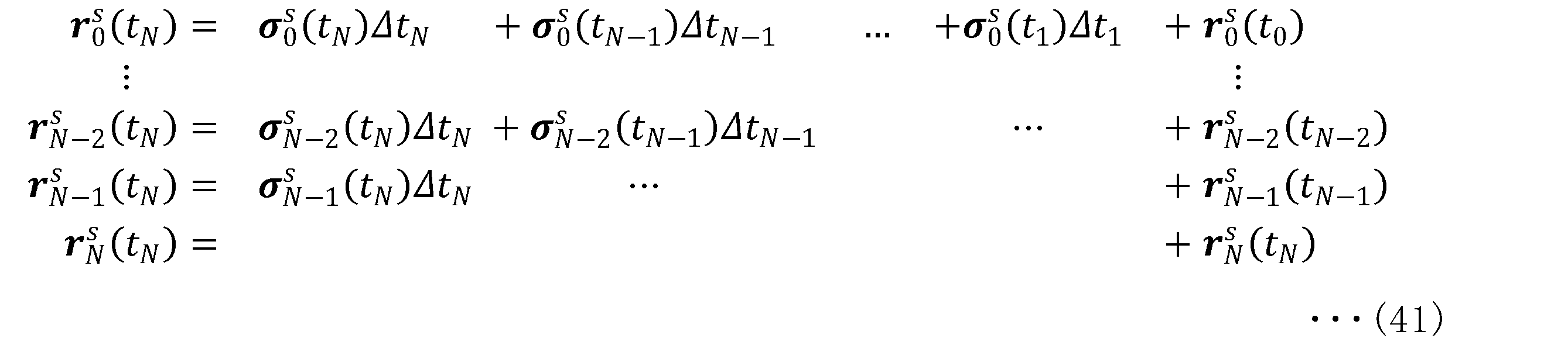
次に、本開示に係る実施形態の第1の変形例について説明する。実施形態の第1の変形例は、図2に示した実施形態に係る信号処理システム1に対して、光検出測距センサ110の走査を制御する構成を追加した例である。
次に、本開示に係る実施形態の第2の変形例について説明する。実施形態の第2の変形例は、図2に示した実施形態に係る信号処理システム1から、イメージセンサ120と画像データに係る処理を行う構成とを省略した例である。
上述した実施形態およびその各変形例では、静止体点群補正部213および動体点群補正部214は、常にFMCW-LiDARにおけるフレームの全体を補正処理の対象としているが、これはこの例に限定されない。例えば、静止体点群補正部213および動体点群補正部214による補正を行うか否かを、当該フレームの全体に設定してもよいし、当該フレーム内に設定した1以上の領域に対して設定してもよい。
(1)
第1のセンサから、それぞれ速度情報と時刻情報とを持つ複数の点を含む速度点群データを受信する受信部と、
前記速度点群データに含まれる少なくとも1つの点に関する少なくとも1つの属性値を、所定の時刻における推定値に基づき補正する補正部と、
前記補正部により補正された前記属性値に対して前記所定の時刻を示す補正時刻情報を付加して送信する送信部と、
を備える、
信号処理装置。
(2)
前記時刻情報は、前記第1のセンサにおいて前記複数の点それぞれが取得された時刻を示す、
前記(1)に記載の信号処理装置。
(3)
前記所定の時刻は、前記第1のセンサによる検出動作のフレームごとに少なくとも1つが与えられる、
前記(1)または(2)に記載の信号処理装置。
(4)
前記受信部は、
さらに、第2のセンサから慣性計測データを受信し、
前記補正部は、
前記推定値を、前記速度情報と、前記時刻情報と、前記慣性計測データと、に基づき算出する、
前記(1)乃至(3)の何れかに記載の信号処理装置。
(5)
前記補正部は、
少なくとも、動体による速度点群である動体速度点群を前記補正の対象とする、
前記(1)乃至(4)の何れかに記載の信号処理装置。
(6)
前記補正部は、
前記動体速度点群を前記補正部による第1の補正の対象とし、静止体による速度点群である静止体速度点群を前記補正部による第2の補正の対象とする、
前記(5)に記載の信号処理装置。
(7)
前記補正部により補正された前記静止体速度点群と、第2のセンサから受信した慣性計測データと、に基づき地図情報を生成する地図生成部、
をさらに備える、
前記(6)に記載の信号処理装置。
(8)
注目領域を抽出する注目領域抽出部、
をさらに備え、
前記受信部は、
さらに、第3のセンサから画像データを受信し、
前記注目領域抽出部は、
前記補正部により補正された前記動体速度点群に基づき推定される、前記動体が含まれる領域に基づき、前記画像データから前記注目領域を抽出する、
前記(5)乃至(7)の何れかに記載の信号処理装置。
(9)
前記動体速度点群と、前記画像データのうち前記注目領域の画像データと、を合成した合成データに基づき前記動体の動作を認識する動作認識部、
をさらに備える、
前記(8)に記載の信号処理装置。
(10)
前記画像データのうち前記注目領域の画像データに基づき画像認識処理を行う画像認識部、
をさらに備える、
前記(8)または(9)に記載の情報処理装置。
(11)
前記受信部は、
前記第1のセンサから、前記第1のセンサによる検出動作の種別を示す種別情報をさらに受信する、
前記(1)乃至(10)の何れかに記載の信号処理装置。
(12)
プロセッサにより実行される、
第1のセンサから、それぞれ速度情報と時刻情報とを持つ複数の点を含む速度点群を受信することと、
前記速度点群に含まれる少なくとも1つの点に関する少なくとも1つの属性値を、所定の時刻における推定値に基づき補正することと、
前記補正することにより補正された前記属性値に対して前記所定の時刻を示す補正時刻情報を付加して送信することと、
を含む、
信号処理方法。
(13)
アプリケーション部からの要求に応じて所定の機能を実行する実行部を備え、
前記実行部は、
第1のセンサから、それぞれ速度情報と時刻情報とを持つ複数の点を含む速度点群を受信する受信部と、
前記速度点群に含まれる少なくとも1つの点に関する少なくとも1つの属性値を、所定の時刻における推定値に基づき補正する補正部と、
前記アプリケーション部からの前記要求を受け取るインタフェース部と、
を含み、
前記インタフェース部は、
前記要求に応じて、前記補正部により補正された前記速度点群を前記アプリケーション部に渡す、
情報処理装置。
(14)
前記時刻情報は、前記第1のセンサにおいて前記複数の点それぞれが取得された時刻を示す、
前記(13)に記載の情報処理装置。
(15)
前記所定の時刻は、前記第1のセンサによる検出動作のフレームごとに少なくとも1つが与えられる、
前記(13)または(14)に記載の情報処理装置。
(16)
前記補正部は、
前記推定値を、前記速度情報と、前記時刻情報と、前記受信部により第2のセンサから受信された慣性計測データと、に基づき算出する、
前記(13)乃至(15)の何れかに記載の情報処理装置。
(17)
前記補正部は、
少なくとも、動体による速度点群である動体速度点群を前記補正の対象とする、
前記(13)乃至(16)の何れかに記載の情報処理装置。
(18)
前記補正部は、
前記動体速度点群を前記補正部による第1の補正の対象とし、静止体による速度点群である静止体速度点群を前記補正部による第2の補正の対象とする、
前記(17)に記載の情報処理装置。
(19)
所定の処理を実行するアプリケーション部と、
所定の機能を実行する実行部に対して前記所定の処理に係る要求を渡すインタフェース部と、
を備え、
前記アプリケーション部は、
前記要求に応じて前記実行部より渡された、前記実行部が第1のセンサから受信したそれぞれ速度情報と時刻情報とを持つ複数の点を含む速度点群に含まれる、少なくとも1つの点に関する少なくとも1つの属性値が所定の時刻における推定値に基づき補正された前記速度点群を、前記インタフェース部を介して受け取り、受け取った該速度点群に基づき、前記所定の処理を実行する、
情報処理装置。
(20)
前記アプリケーション部は、
それぞれ前記インタフェース部を介して受け取った、前記推定値に基づき補正された静止体による速度点群である静止体速度点群と、前記実行部が第2のセンサから受信した慣性計測データと、に基づき地図情報を生成する地図生成部、
を含む、
前記(19)に記載の情報処理装置。
(21)
前記アプリケーション部は、
前記インタフェース部を介して受け取った、前記実行部が第3のセンサから受信した画像データに対する注目領域を、前記インタフェース部を介して受け取った、前記推定値に基づき補正された動体による速度点群である動体速度点群に基づき推定される、前記動体が含まれる領域に基づき抽出する注目領域抽出部、
を含む、
前記(19)または(20)に記載の情報処理装置。
(22)
前記アプリケーション部は、
前記動体速度点群と、前記画像データのうち前記注目領域の画像データと、を合成した合成データに基づき前記動体の動作を認識する動作認識部、
を含む、
前記(21)に記載の情報処理装置。
(23)
前記アプリケーション部は、
前記画像データのうち前記注目領域の画像データに基づき画像認識処理を行う画像認識部、
を含む、
前記(21)または(22)に記載の情報処理装置。
10,10a センサ部
20,20a,20b 信号処理部
30 情報処理部
40 走査線
41,41a,41b,41st 射出ポイント
421,422,42N 走査線
45 角度範囲
46 走査範囲
50a,50b,52 物体
60a,60b,60c フレーム
61 画素
100 IMU
110 光検出測距センサ
111 光走査部
112 光送受信部
113 受信信号処理部
114 光走査制御部
115,201 送信部
120 イメージセンサ
130 同期信号生成部
200 受信部
210 センサ位置姿勢推定部
211 動体・静止体分離部
212 センサ速度推定部
213 静止体点群補正部
214 動体点群補正部
220 地図変換部
221 動体状態推定部
222 3D/2D変換部
223 ROI抽出部
224 合成部
225 動作認識部
226 画像認識部
230 制御通信部
231 走査制御部
232 パラメータ設定部
400 センサ位置姿勢推定処理
401 静止体動体弁別処理
402 センサ速度推定処理
403,404 点群補正処理
405 動体検出処理
1000 センサ群
1010 ファームウェア
2000,3000 プロセッサ
2010,3010 ライブラリ部
2020,3020 アプリケーション部
2030 OS
2040 API呼出部
2041 API処理部
Claims (20)
- 第1のセンサから、それぞれ速度情報と時刻情報とを持つ複数の点を含む速度点群データを受信する受信部と、
前記速度点群データに含まれる少なくとも1つの点に関する少なくとも1つの属性値を、所定の時刻における推定値に基づき補正する補正部と、
前記補正部により補正された前記属性値に対して前記所定の時刻を示す補正時刻情報を付加して送信する送信部と、
を備える、
信号処理装置。 - 前記時刻情報は、前記第1のセンサにおいて前記複数の点それぞれが取得された時刻を示す、
請求項1に記載の信号処理装置。 - 前記所定の時刻は、前記第1のセンサによる検出動作のフレームごとに少なくとも1つが与えられる、
請求項1に記載の信号処理装置。 - 前記受信部は、
さらに、第2のセンサから慣性計測データを受信し、
前記補正部は、
前記推定値を、前記速度情報と、前記時刻情報と、前記慣性計測データと、に基づき算出する、
請求項1に記載の信号処理装置。 - 前記補正部は、
少なくとも、動体による速度点群である動体速度点群を前記補正の対象とする、
請求項1に記載の信号処理装置。 - 前記補正部は、
前記動体速度点群を前記補正部による第1の補正の対象とし、静止体による速度点群である静止体速度点群を前記補正部による第2の補正の対象とする、
請求項5に記載の信号処理装置。 - 前記補正部により補正された前記静止体速度点群と、第2のセンサから受信した慣性計測データと、に基づき地図情報を生成する地図生成部、
をさらに備える、
請求項6に記載の信号処理装置。 - 注目領域を抽出する注目領域抽出部、
をさらに備え、
前記受信部は、
さらに、第3のセンサから画像データを受信し、
前記注目領域抽出部は、
前記補正部により補正された前記動体速度点群に基づき推定される、前記動体が含まれる領域に基づき、前記画像データから前記注目領域を抽出する、
請求項5に記載の信号処理装置。 - 前記動体速度点群と、前記画像データのうち前記注目領域の画像データと、を合成した合成データに基づき前記動体の動作を認識する動作認識部、
をさらに備える、
請求項8に記載の信号処理装置。 - 前記受信部は、
前記第1のセンサから、前記第1のセンサによる検出動作の種別を示す種別情報をさらに受信する、
請求項1に記載の信号処理装置。 - プロセッサにより実行される、
第1のセンサから、それぞれ速度情報と時刻情報とを持つ複数の点を含む速度点群を受信することと、
前記速度点群に含まれる少なくとも1つの点に関する少なくとも1つの属性値を、所定の時刻における推定値に基づき補正することと、
前記補正することにより補正された前記属性値に対して前記所定の時刻を示す補正時刻情報を付加して送信することと、
を含む、
信号処理方法。 - アプリケーション部からの要求に応じて所定の機能を実行する実行部を備え、
前記実行部は、
第1のセンサから、それぞれ速度情報と時刻情報とを持つ複数の点を含む速度点群を受信する受信部と、
前記速度点群に含まれる少なくとも1つの点に関する少なくとも1つの属性値を、所定の時刻における推定値に基づき補正する補正部と、
前記アプリケーション部からの前記要求を受け取るインタフェース部と、
を含み、
前記インタフェース部は、
前記要求に応じて、前記補正部により補正された前記速度点群を前記アプリケーション部に渡す、
情報処理装置。 - 前記時刻情報は、前記第1のセンサにおいて前記複数の点それぞれが取得された時刻を示す、
請求項12に記載の情報処理装置。 - 前記所定の時刻は、前記第1のセンサによる検出動作のフレームごとに少なくとも1つが与えられる、
請求項12に記載の情報処理装置。 - 前記補正部は、
前記推定値を、前記速度情報と、前記時刻情報と、前記受信部により第2のセンサから受信された慣性計測データと、に基づき算出する、
請求項12に記載の情報処理装置。 - 前記補正部は、
少なくとも、動体による速度点群である動体速度点群を前記補正の対象とする、
請求項12に記載の情報処理装置。 - 所定の処理を実行するアプリケーション部と、
所定の機能を実行する実行部に対して前記所定の処理に係る要求を渡すインタフェース部と、
を備え、
前記アプリケーション部は、
前記要求に応じて前記実行部より渡された、前記実行部が第1のセンサから受信したそれぞれ速度情報と時刻情報とを持つ複数の点を含む速度点群に含まれる、少なくとも1つの点に関する少なくとも1つの属性値が所定の時刻における推定値に基づき補正された前記速度点群を、前記インタフェース部を介して受け取り、受け取った該速度点群に基づき、前記所定の処理を実行する、
情報処理装置。 - 前記アプリケーション部は、
それぞれ前記インタフェース部を介して受け取った、前記推定値に基づき補正された静止体による速度点群である静止体速度点群と、前記実行部が第2のセンサから受信した慣性計測データと、に基づき地図情報を生成する地図生成部、
を含む、
請求項17に記載の情報処理装置。 - 前記アプリケーション部は、
前記インタフェース部を介して受け取った、前記実行部が第3のセンサから受信した画像データに対する注目領域を、前記インタフェース部を介して受け取った、前記推定値に基づき補正された動体による速度点群である動体速度点群に基づき推定される、前記動体が含まれる領域に基づき抽出する注目領域抽出部、
を含む、
請求項17に記載の情報処理装置。 - 前記アプリケーション部は、
前記動体速度点群と、前記画像データのうち前記注目領域の画像データと、を合成した合成データに基づき前記動体の動作を認識する動作認識部、
を含む、
請求項19に記載の情報処理装置。
Priority Applications (4)
| Application Number | Priority Date | Filing Date | Title |
|---|---|---|---|
| US18/878,655 US20260003075A1 (en) | 2022-07-29 | 2023-07-21 | Signal processing apparatus, signal processing method, and information processing apparatus |
| DE112023003273.4T DE112023003273T5 (de) | 2022-07-29 | 2023-07-21 | Signalverarbeitungsvorrichtung, signalverarbeitungsverfahren und informationsverarbeitungsvorrichtung |
| JP2024537663A JPWO2024024656A1 (ja) | 2022-07-29 | 2023-07-21 | |
| CN202380055837.3A CN119630988A (zh) | 2022-07-29 | 2023-07-21 | 信号处理装置、信号处理方法和信息处理装置 |
Applications Claiming Priority (2)
| Application Number | Priority Date | Filing Date | Title |
|---|---|---|---|
| JP2022122136 | 2022-07-29 | ||
| JP2022-122136 | 2022-07-29 |
Publications (1)
| Publication Number | Publication Date |
|---|---|
| WO2024024656A1 true WO2024024656A1 (ja) | 2024-02-01 |
Family
ID=89706479
Family Applications (1)
| Application Number | Title | Priority Date | Filing Date |
|---|---|---|---|
| PCT/JP2023/026725 Ceased WO2024024656A1 (ja) | 2022-07-29 | 2023-07-21 | 信号処理装置および信号処理方法、ならびに、情報処理装置 |
Country Status (5)
| Country | Link |
|---|---|
| US (1) | US20260003075A1 (ja) |
| JP (1) | JPWO2024024656A1 (ja) |
| CN (1) | CN119630988A (ja) |
| DE (1) | DE112023003273T5 (ja) |
| WO (1) | WO2024024656A1 (ja) |
Cited By (1)
| Publication number | Priority date | Publication date | Assignee | Title |
|---|---|---|---|---|
| WO2026084808A1 (en) * | 2024-10-18 | 2026-04-23 | Qualcomm Incorporated | Velocity estimation distortion correction |
Citations (4)
| Publication number | Priority date | Publication date | Assignee | Title |
|---|---|---|---|---|
| JP2016138878A (ja) * | 2009-02-20 | 2016-08-04 | デジタル・シグナル・コーポレーション | ライダーとビデオ測定を使用する3次元画像の生成システム及び方法 |
| US20200292706A1 (en) * | 2019-03-14 | 2020-09-17 | Aeva, Inc. | Velocity estimation using doppler per point lidar systems |
| JP2022510198A (ja) * | 2018-11-29 | 2022-01-26 | エスゼット ディージェイアイ テクノロジー カンパニー リミテッド | 移動プラットフォームの周囲の環境を検出するシステム及びその方法 |
| WO2022123887A1 (ja) * | 2020-12-11 | 2022-06-16 | パナソニックIpマネジメント株式会社 | 測距装置および移動体 |
-
2023
- 2023-07-21 WO PCT/JP2023/026725 patent/WO2024024656A1/ja not_active Ceased
- 2023-07-21 US US18/878,655 patent/US20260003075A1/en active Pending
- 2023-07-21 JP JP2024537663A patent/JPWO2024024656A1/ja active Pending
- 2023-07-21 CN CN202380055837.3A patent/CN119630988A/zh active Pending
- 2023-07-21 DE DE112023003273.4T patent/DE112023003273T5/de active Pending
Patent Citations (4)
| Publication number | Priority date | Publication date | Assignee | Title |
|---|---|---|---|---|
| JP2016138878A (ja) * | 2009-02-20 | 2016-08-04 | デジタル・シグナル・コーポレーション | ライダーとビデオ測定を使用する3次元画像の生成システム及び方法 |
| JP2022510198A (ja) * | 2018-11-29 | 2022-01-26 | エスゼット ディージェイアイ テクノロジー カンパニー リミテッド | 移動プラットフォームの周囲の環境を検出するシステム及びその方法 |
| US20200292706A1 (en) * | 2019-03-14 | 2020-09-17 | Aeva, Inc. | Velocity estimation using doppler per point lidar systems |
| WO2022123887A1 (ja) * | 2020-12-11 | 2022-06-16 | パナソニックIpマネジメント株式会社 | 測距装置および移動体 |
Cited By (1)
| Publication number | Priority date | Publication date | Assignee | Title |
|---|---|---|---|---|
| WO2026084808A1 (en) * | 2024-10-18 | 2026-04-23 | Qualcomm Incorporated | Velocity estimation distortion correction |
Also Published As
| Publication number | Publication date |
|---|---|
| JPWO2024024656A1 (ja) | 2024-02-01 |
| DE112023003273T5 (de) | 2025-09-04 |
| US20260003075A1 (en) | 2026-01-01 |
| CN119630988A (zh) | 2025-03-14 |
Similar Documents
| Publication | Publication Date | Title |
|---|---|---|
| US11841431B2 (en) | System and method for increasing resolution of images obtained from a three-dimensional measurement system | |
| US9435891B2 (en) | Time of flight camera with stripe illumination | |
| CN108020825B (zh) | 激光雷达、激光摄像头、视频摄像头的融合标定系统及方法 | |
| JP2016138878A (ja) | ライダーとビデオ測定を使用する3次元画像の生成システム及び方法 | |
| US20190266425A1 (en) | Identification apparatus, identification method, and non-transitory tangible recording medium storing identification program | |
| JP4193886B2 (ja) | 画像表示装置 | |
| EP2890952A2 (en) | System and method for refining coordinate-based three-dimensional images obtained from a three-dimensional measurement system | |
| KR102240817B1 (ko) | 티오에프 카메라에서 깊이 지도 생성 방법 | |
| JP2012518793A5 (ja) | ||
| WO2022195954A1 (ja) | センシングシステム | |
| US20240134053A1 (en) | Time-of-flight data generation circuitry and time-of-flight data generation method | |
| JP2018063222A (ja) | 距離測定装置、距離測定方法及びプログラム | |
| US20260003075A1 (en) | Signal processing apparatus, signal processing method, and information processing apparatus | |
| JP2023046746A (ja) | 情報処理装置、制御方法、およびプログラム | |
| US20230396746A1 (en) | Image projection system and image projection method | |
| JP7173342B2 (ja) | レーダ装置、イメージング方法およびイメージングプログラム | |
| WO2024024663A1 (ja) | 認識システム、認識方法および認識装置 | |
| WO2021070814A1 (ja) | 同期装置、同期方法、同期プログラム | |
| US20250224516A1 (en) | Information processing apparatus, system, information processing method, information processing program, and computer system | |
| EP4094096B1 (en) | A method and system for generating a colored tridimensional map | |
| JP5803534B2 (ja) | 光通信装置及びプログラム | |
| JP2010157910A (ja) | 画像表示装置 | |
| JP2019007921A (ja) | 情報出力システム、情報出力装置、およびプログラム | |
| KR20230156697A (ko) | 정보 처리 장치 및 정보 처리 방법, 그리고 센싱 시스템 |
Legal Events
| Date | Code | Title | Description |
|---|---|---|---|
| 121 | Ep: the epo has been informed by wipo that ep was designated in this application |
Ref document number: 23846387 Country of ref document: EP Kind code of ref document: A1 |
|
| WWE | Wipo information: entry into national phase |
Ref document number: 2024537663 Country of ref document: JP |
|
| WWE | Wipo information: entry into national phase |
Ref document number: 18878655 Country of ref document: US |
|
| WWE | Wipo information: entry into national phase |
Ref document number: 202380055837.3 Country of ref document: CN |
|
| WWE | Wipo information: entry into national phase |
Ref document number: 112023003273 Country of ref document: DE |
|
| WWP | Wipo information: published in national office |
Ref document number: 202380055837.3 Country of ref document: CN |
|
| 122 | Ep: pct application non-entry in european phase |
Ref document number: 23846387 Country of ref document: EP Kind code of ref document: A1 |
|
| WWP | Wipo information: published in national office |
Ref document number: 112023003273 Country of ref document: DE |
|
| WWP | Wipo information: published in national office |
Ref document number: 18878655 Country of ref document: US |