WO2024024563A1 - 繊維強化プラスチックおよびその製造方法 - Google Patents
繊維強化プラスチックおよびその製造方法 Download PDFInfo
- Publication number
- WO2024024563A1 WO2024024563A1 PCT/JP2023/026210 JP2023026210W WO2024024563A1 WO 2024024563 A1 WO2024024563 A1 WO 2024024563A1 JP 2023026210 W JP2023026210 W JP 2023026210W WO 2024024563 A1 WO2024024563 A1 WO 2024024563A1
- Authority
- WO
- WIPO (PCT)
- Prior art keywords
- fiber
- protrusion
- plate
- reinforced plastic
- unidirectional
- Prior art date
- Legal status (The legal status is an assumption and is not a legal conclusion. Google has not performed a legal analysis and makes no representation as to the accuracy of the status listed.)
- Ceased
Links
Images



Classifications
-
- B—PERFORMING OPERATIONS; TRANSPORTING
- B29—WORKING OF PLASTICS; WORKING OF SUBSTANCES IN A PLASTIC STATE IN GENERAL
- B29C—SHAPING OR JOINING OF PLASTICS; SHAPING OF MATERIAL IN A PLASTIC STATE, NOT OTHERWISE PROVIDED FOR; AFTER-TREATMENT OF THE SHAPED PRODUCTS, e.g. REPAIRING
- B29C43/00—Compression moulding, i.e. applying external pressure to flow the moulding material; Apparatus therefor
- B29C43/32—Component parts, details or accessories; Auxiliary operations
- B29C43/34—Feeding the material to the mould or the compression means
-
- B—PERFORMING OPERATIONS; TRANSPORTING
- B29—WORKING OF PLASTICS; WORKING OF SUBSTANCES IN A PLASTIC STATE IN GENERAL
- B29C—SHAPING OR JOINING OF PLASTICS; SHAPING OF MATERIAL IN A PLASTIC STATE, NOT OTHERWISE PROVIDED FOR; AFTER-TREATMENT OF THE SHAPED PRODUCTS, e.g. REPAIRING
- B29C70/00—Shaping composites, i.e. plastics material comprising reinforcements, fillers or preformed parts, e.g. inserts
- B29C70/04—Shaping composites, i.e. plastics material comprising reinforcements, fillers or preformed parts, e.g. inserts comprising reinforcements only, e.g. self-reinforcing plastics
- B29C70/06—Fibrous reinforcements only
- B29C70/10—Fibrous reinforcements only characterised by the structure of fibrous reinforcements, e.g. hollow fibres
-
- B—PERFORMING OPERATIONS; TRANSPORTING
- B29—WORKING OF PLASTICS; WORKING OF SUBSTANCES IN A PLASTIC STATE IN GENERAL
- B29C—SHAPING OR JOINING OF PLASTICS; SHAPING OF MATERIAL IN A PLASTIC STATE, NOT OTHERWISE PROVIDED FOR; AFTER-TREATMENT OF THE SHAPED PRODUCTS, e.g. REPAIRING
- B29C70/00—Shaping composites, i.e. plastics material comprising reinforcements, fillers or preformed parts, e.g. inserts
- B29C70/04—Shaping composites, i.e. plastics material comprising reinforcements, fillers or preformed parts, e.g. inserts comprising reinforcements only, e.g. self-reinforcing plastics
- B29C70/28—Shaping operations therefor
- B29C70/40—Shaping or impregnating by compression not applied
- B29C70/42—Shaping or impregnating by compression not applied for producing articles of definite length, i.e. discrete articles
Definitions
- the present invention relates to a fiber-reinforced plastic having a shape having a plate-like part and a protrusion protruding from at least one side of the plate-like part.
- the present invention relates to fiber-reinforced plastics made of resin.
- Fiber-reinforced plastics made of reinforcing fibers and matrix resin have high specific strength, high specific modulus, excellent mechanical properties, and high functional properties such as weather resistance and chemical resistance, so they are used in industry, sports, and medicine. It is expected to be used in a wide range of fields such as information and communication, and is attracting attention.
- Autoclave molding and press molding are methods for producing fiber-reinforced plastics with highly functional properties.
- autoclave molding semi-cured sheets or fabrics of continuous reinforcing fibers called prepregs are impregnated with a thermosetting resin as a matrix resin, and are laminated and heated in a high-temperature, high-pressure oven (autoclave). By applying pressure, the matrix resin of the thermosetting resin is cured, and a fiber-reinforced plastic is molded.
- press molding the above-mentioned prepregs are laminated and put into a mold, heated and pressed in a press to harden the thermosetting matrix resin, or impregnated with thermoplastic resin as the matrix resin.
- thermoplastic resin is softened or melted, molded, and then cooled and demolded.
- prepregs impregnated with reinforcing fibers using thermosetting resins with a fast curing speed as matrix resin molded products can be produced in large quantities in a short period of time. In recent years, it has attracted attention as a molding method with high properties.
- the desired fiber-reinforced plastic is divided into plate-shaped parts or rib-shaped parts.
- each part may be molded separately and then joined using adhesive or heat fusion.
- the bonding process is time-consuming and costly, and the strength and rigidity of the joint is lower than other parts, so the joint breaks first. It was difficult to fully demonstrate.
- appearance quality may be required.
- the appearance of the product is an element that increases the added value of the product.
- the reinforcing fibers flow violently during molding, disrupting the above-mentioned characteristic appearance, making it difficult to achieve the desired appearance quality.
- Possible methods include increasing the thickness of the molded product to reduce the effects of changes in wall thickness and the flow of reinforcing fibers caused by ribs, etc., or attaching a separate layer with a high appearance quality to the design surface. , improvements are desired in terms of lightness and production efficiency.
- Patent Documents 1 and 2 Attempts to improve the problems of such conventional techniques have been proposed.
- Patent Document 1 discloses a fiber-reinforced method in which a rib shape is formed by laminating at least two prepreg base materials in which cuts are inserted and the fiber length is adjusted to 10 to 100 mm, and press-molding is performed. A method of manufacturing plastics has been proposed. Although this method has been studied from the viewpoint of the rigidity and material balance of the molded product, the impact on the appearance quality has not been considered, and it is aimed at molding thick parts, so there are issues with weight reduction. be.
- Patent Document 2 discloses that in a fiber-reinforced plastic made of a laminate of woven fabric prepreg and discontinuous fiber prepreg, when the calorific value of the resin of each prepreg satisfies a predetermined condition, the fiber-reinforced plastic has less disordered texture of the fabric. It has been shown that it can be obtained. Although this document also describes the appearance quality during rib molding, it does not describe the width of the ribs or the thickness of the plate-like portion, and its reinforcing effect and lightness are not clear.
- An object of the present invention is to improve the problems of the prior art and provide a fiber-reinforced plastic having protrusions that is lightweight and has excellent mechanical properties and appearance quality.
- a large number of reinforcing fibers are contained in a matrix resin inside the plate-like part. It has at least one layer arranged in one direction (unidirectional layer), the thickness t of the plate-like part is 0.3 mm or more and 1.8 mm or less, and the maximum width w of the protrusion and the plate
- a fiber-reinforced plastic whose ratio w/t of the thickness t of the shaped portion is 0.1 or more and 27 or less.
- the plate-shaped part has a plurality of layers made of reinforcing fibers and matrix resin, and the protrusion part is formed only on one side of the plate-shaped part, and forms the outermost layer on the opposite side.
- the outermost layer of the plate-like part on the side where the protrusion is located is the unidirectional layer, and the fiber basis weight of the outermost unidirectional layer is higher than that of at least one other layer in the plate-like part.
- the plate-like part has a plurality of layers made of reinforcing fibers and matrix resin, and has the protrusion on only one side of the plate-like part, and the plate-like part has the protrusion on only one side, and the surface of the plate other than the outermost layer of the surface having the protrusion has a plurality of layers.
- the plate-shaped portion has a non-unidirectional layer, and the ratio w/ of the maximum width w of the protrusion and the total thickness t' of the unidirectional layers located closer to the protrusion than the non-unidirectional layer.
- t' is 0.1 or more and 27 or less.
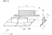
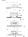
- FIG. 2 is a conceptual diagram showing an example of a protrusion and a plate-shaped portion that constitute the fiber-reinforced plastic according to the present invention.
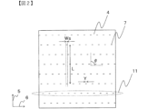
- FIG. 3 is an explanatory diagram showing the definitions of the fiber length, the length of the cut, the angle, and the projected length in the cut-inserted prepreg.
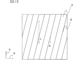
- This is an example of a cut pattern of the cut-inserted prepreg (an example having parallel and continuous cuts).
- This is another example of the cut pattern of the cut-inserted prepreg (an example having parallel and interrupted cuts).
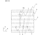
- This is another example of the cut pattern of the cut-inserted prepreg an example in which the angle with the reinforcing fiber is constant and the number of positive and negative cuts is approximately half each).
- FIG. 1 is an example of a longitudinal cross-sectional view of a fiber-reinforced plastic having protrusions.
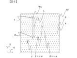
- FIG. 2 is a schematic diagram showing a deviation on the surface of fiber-reinforced plastic (the surface opposite to the surface having protrusions).
- This is another example of a longitudinal cross-sectional view of a fiber-reinforced plastic having a protrusion (an example in which the outermost layer on the side opposite to the side having the protrusion is a non-unidirectional layer).
- FIG. 1 is an example of a longitudinal cross-sectional view of a fiber-reinforced plastic having protrusions.
- FIG. 2 is a schematic diagram showing a deviation on the surface of fiber-reinforced plastic (the surface opposite to the surface having protrusions).
- This is another example of a longitudinal cross-sectional view of a fiber-reinforced plastic having a protrusion (an example in which the outermost layer on the side opposite to the side having the protrusion
- FIG. 3 is a schematic diagram showing an example of the shape of a protrusion protruding from a plate-like portion.
- FIG. 2 is a conceptual diagram showing the orientation direction of reinforcing fibers in a protrusion and a plate-shaped portion that constitute fiber-reinforced plastic. It is another example of the longitudinal cross-sectional view of the fiber reinforced plastic which has a protrusion part.
- the fiber-reinforced plastic of the present invention has at least one layer in which a large number of reinforcing fibers are arranged in one direction in a matrix resin (hereinafter sometimes referred to as a unidirectional layer). As shown, the fiber-reinforced plastic has a plate-like portion 100 and at least one protrusion 200 protruding from at least one side of the plate-like portion 100. As described above, inside the plate-shaped portion 100, there is at least one unidirectional layer.
- the shape of the protrusion when viewed from above the surface of the plate-like part is defined as the planar shape of the protrusion
- the direction in which the planar shape of the protrusion extends is defined as the direction in which the protrusion extends (hereinafter referred to as , sometimes referred to as the length direction)
- the direction perpendicular to the length direction in the planar shape is the width direction of the protrusion.
- the direction in which the planar shape extends refers to the long axis direction if the planar shape is an ellipse, or the direction of the long side if the planar shape is a rectangle. The direction of the long side of the rectangle with the smallest area circumscribing the shape.
- the cross section of the protrusion that is parallel to the length direction of the protrusion and perpendicular to the planar direction of the plate-like part, where the length direction of the protrusion is maximum is called the cross section of the protrusion
- the width of the protrusion is A cross section parallel to the width direction of the protrusion and perpendicular to the planar direction of the plate-like part where the direction is maximum.
- a cross section perpendicular to the planar direction of the plate-like portion along the short axis is a cross-section 22 of the protrusion
- a cross-section perpendicular to the planar direction of the plate-like portion along the short axis is a longitudinal cross-section 23 of the protrusion.
- the planar shape can be defined by a combination of rectangles or ellipses (X-shape, V-shape, H-shape, or Y-shape, etc.).
- the protrusion is interpreted to have multiple length directions.
- the planar shape of the protrusion is X-shaped or V-shaped, it is interpreted that it has two longitudinal directions, and when it is H-shaped or Y-shaped, it has three longitudinal directions, and the above-mentioned plane is interpreted accordingly.
- a shape is broken down into multiple shapes and interpreted as having multiple cross sections and longitudinal sections corresponding to each direction.
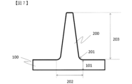
- FIG. 7 shows a longitudinal cross-sectional view of the protrusion raised from the plate-like portion.
- the width of the protrusion 200 may be different at the tip and base as shown in FIG. 7, or may be the same. However, it is preferable that the width of the base is wider than that of the tip because it is easier to take out from the mold when demolding, and stress concentration when a load is applied during use can be alleviated. Further, when the tip and the base of the protrusion have different shapes as shown in FIG. 7, the shape at the base is the planar shape of the protrusion.
- the protruding portion 200 and the plate-like portion 100 are preferably connected by a curved surface, and the radius of curvature R thereof is preferably 2 mm or less, more preferably 1 mm or less.
- the radius of curvature R is 2 mm or less, the volume of the root of the protrusion does not become excessively large, so that the protrusion is sufficiently filled with a unidirectional prepreg as described below. Therefore, "resin rich" with a high resin ratio is less likely to occur, causing dents on the design side (if the protrusions are only on one side, the side opposite to the side where the protrusions are present) and reinforcing fibers. It is possible to suppress deterioration in appearance quality due to the occurrence of eye wrinkles.
- the boundary between the protrusion 200 and the plate-shaped portion 100 (hereinafter referred to as the joint or contact point) will become sharp, and the reinforcing fibers may come into contact and be cut, or processing of the mold may become difficult. Therefore, it is preferable to provide a thickness of about 0.2 mm.
- the maximum width of the protrusion in the longitudinal section is defined as the maximum width w of the protrusion. That is, in the case of the shape as shown in FIG. 7, the distance 202 between both ends of the contact between the plate-shaped portion 100 and the protrusion 200 is the maximum width w of the protrusion. Furthermore, when the plate-like portion and the protrusion are connected by a curved surface, the maximum width refers to the interval that includes the curved surface.
- the maximum width of the protrusion is preferably 8 mm or less, more preferably 5 mm or less.
- the maximum width of the protrusion is 8 mm or less over the entire area of the protrusion, a fiber-reinforced plastic with high appearance quality can be obtained even if the thickness of the plate-like part is as thin as 1.8 mm or less, resulting in thinner walls and lighter weight. can. Further, as described above, when the protrusion extends in two different directions and has a plurality of longitudinal sections, the maximum width in the longitudinal section where the maximum width is the largest is defined as the maximum width of the protrusion.
- the thickness 101 of the plate-like part is in the range of 0.3 to 1.8 mm, and this thickness can be arbitrarily designed by adjusting the amounts of fibers and matrix resin used. .
- methods for adjusting the amount of fibers and matrix resin used include changing the amount of matrix resin, changing the type of fiber, etc. There is.
- the thickness t of the plate-like portion is 0.3 to 1.8 mm. Furthermore, if rigidity and weight reduction are particularly required for the plate-like portion, the thickness is preferably 0.5 to 1.2 mm. In particular, when fiber-reinforced plastics are used in components that require strict weight reduction, such as golf club heads, the weight distribution design has a significant impact on flight distance and feel, so designs in 0.1g increments are required. There are cases.
- the thickness of the plate part differs by 0.1 mm, the weight will change by about 1 to 2 g. Therefore, it is very important to adjust the thickness of the plate-shaped portion, which has a large influence on the weight.
- the thickness of the plate portion exceeds 1.8 mm, it is difficult to apply the plate portion to a member that requires weight reduction.
- the thickness of the plate-like part refers to the thickness at the point of contact between the plate-like part 100 and the protrusion 200 in a longitudinal section (if the plate-like part and the protrusion are connected by a curved surface, the contact point between the curved surface and the plate-like part). It refers to the thickness 101 of the plate-like portion.
- the ratio w/t of the maximum width w [mm] of the protruding portion and the thickness t [mm] of the plate-like portion is 0.1 or more and 27 or less.
- the upper limit is preferably 10 or less, more preferably 5 or less. If w/t exceeds 27, the reinforcing fibers on the designed surface side may become dented due to insufficient reinforcing fibers filling the protrusions, or resin richness may occur at the base of the protrusions, causing the reinforcing fibers on the designed surface side to flow easily. The appearance quality may deteriorate due to twisting of the reinforcing fibers.
- Figure 8 shows a schematic diagram of the design surface.
- (A) shows a state in which the reinforcing fibers 401 are aligned in one direction and there is no kink
- (B) shows a state in which there is kink 402.
- the greater the degree of kink the worse the appearance quality becomes.
- the ratio is preferably 0.1 or more, more preferably 2 or more, and even more preferably 3 or more.
- both good appearance quality and improved strength of the molded product can be further expected.
- the thickness 101 of the plate-like portion in FIG. 7 is different on the left and right sides of the protrusion, the smaller thickness of the plate-like portion is set as the thickness t of the plate-like portion.
- the ratio of the length corresponding to the thickness of the shaped part satisfies 27 or less. However, if, for example, there is a situation where the appearance quality is not required in a part and a wider protrusion is desired, the above ratio exceeds 27 in a part of the cross section other than the vertical cross section. It may be provided.
- the maximum width of the protrusion and the thickness of the plate can be measured by measuring the distance between both ends of the joint between the protrusion and the plate with a caliper or micrometer, or by observing the cross section with a microscope. , may be calculated by image analysis.
- the height 203 of the protrusion of the fiber-reinforced plastic of the present invention is not particularly limited and can be arbitrarily designed, but is preferably 0.1 to 50 mm, more preferably 0.1 to 20 mm, and 1 to 10 mm. is even more preferable.
- the height of the protrusion is determined based on the smaller thickness of the plate-like part.
- the height of the protrusion exceeds 50 mm, unfilled areas may occur where the unidirectional prepreg described below does not fill up to the tip of the protrusion, and if the height is less than 0.1 mm, the reinforcing effect will decrease and the protrusion will There is a possibility that the meaning of establishing it will be diminished.
- the height of the protrusion is 1 to 6 mm, the amount of the fiber base material constituting the plate-like part that flows into the groove for forming the protrusion of the mold is not too large, and the design of the fiber reinforced plastic is improved. This is most preferable because it can more reliably prevent the occurrence of disturbances in fiber orientation and surface depressions.
- At least one layer other than the outermost layer of the surface having the protrusion of the plate-shaped portion 100 is a non-unidirectional layer 102. Furthermore, as shown in FIG. 9, it is preferable that the outermost layer of the plate-shaped portion 100 on the side opposite to the surface on which the protrusions are provided is the non-unidirectional layer 102.
- non-unidirectional layer refers to a layer in which reinforcing fibers are not arranged in only one direction, that is, a layer in which the fibers are oriented in at least two directions. More specific examples of non-unidirectional layers include those in which fibers are arranged in at least two determined directions, such as in woven fabrics, and those in which fibers are randomly oriented, such as in non-woven fabrics. Yes, but there are no particular limitations.
- the non-unidirectional layer means one of the layers constituting the plate-like part of the fiber-reinforced plastic, and the material corresponding to the non-unidirectional layer before molding the fiber-reinforced plastic is , called non-unidirectionally reinforced fiber sheet.
- the non-unidirectional reinforced fiber sheet may have any form as long as the reinforcing fibers are arranged not only in one direction but in multiple directions, and does not contain a matrix resin. It may be in the form of a dry sheet, or it may be in a state in which at least a portion of the region is pre-impregnated with a matrix resin.
- the ratio w/t' of the maximum width w [mm] of the protrusion and the total thickness t' [mm] of the unidirectional layer is preferably 0.1 or more and 27 or less.
- the upper limit is more preferably 10 or less, most preferably 5 or less.
- the reinforcing fibers on the designed surface may flow due to insufficient reinforcing fiber sheets filling the protrusions, causing dents on the designed surface, or resin richness occurring at the base of the protrusions. This may cause misalignment of the fiber direction, resulting in a deterioration in appearance quality.
- the smaller w/t' is, the better; however, from the viewpoint of filling the reinforcing fibers into the protrusions and the strength of the protrusions, it is preferably 0.1 or more, more preferably 2 or more, and even more preferably 3 or more. .
- the total thickness 103 of the unidirectional layers in FIG. 9 is different on the left and right sides of the protrusion, the smaller total thickness is set as the total thickness t'.
- the shape of the protruding portion raised from the plate-like portion is not particularly limited, and can take various forms depending on the purpose.
- the protrusion may be polygonal (for example, rectangular), circular, X-shaped, V-shaped, H-shaped, I-shaped, or Y-shaped. , an L-shaped protrusion, and the like. Moreover, you may combine these.
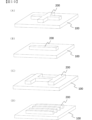
- FIG. 10(A) shows an embodiment with an X-shaped protrusion
- FIG. 10(B) shows an I-shaped protrusion
- FIG. 10(C) shows an H-shaped protrusion
- FIG. 10(D) shows an I-shaped protrusion.
- An embodiment having a plurality of protrusions is shown.
- cross-sectional shape and longitudinal cross-sectional shape of the protrusion include, for example, a polygon (for example, a rectangle or a triangle) or a semicircle.
- the cross-sectional shape and height dimensions of the protrusions it is possible to make all of the multiple protrusions the same shape and dimensions, but it is possible to change them according to the uneven shape and curvature of the fiber reinforced plastic. It is also possible to create a portion that does not have the above shape.
- protrusions can be placed anywhere on the plate-like part. Furthermore, the arrangement positions of the protrusions can be confirmed in a top view of the fiber-reinforced plastic, where the appearance of all the protrusions can be seen.
- the arrangement position of the protrusion is not limited to one location, but can be arranged at two or more locations. That is, it is also possible to install protrusions of the same shape or different shapes at two or more locations.
- the number of protrusions it is determined that the parts where the plate-like parts are visible when viewed from above are not considered protrusions, and the smallest protrusion surrounded by the plate-like parts is recognized as one independent protrusion. and count the numbers.
- ribs are provided as protrusions, in order to achieve both weight reduction and rigidity improvement of the fiber-reinforced plastic according to the present invention, it is preferable to arrange the ribs not only at one location but at two or more locations. By doing so, the reinforcement range of the plate portion can be expanded.
- ribs are arranged at two or more locations, a reinforcing effect can be obtained by arranging the ribs in parallel with each other in their length directions. In that case, each rib may be provided discontinuously or intermittently.
- the length directions of multiple ribs are not parallel to each other (such as a V-shape)
- the length directions can be set in any direction according to the mechanical properties required for fiber-reinforced plastic. It is possible to arrange it so that
- the shape of the ribs is not only a single character shape with only one direction in the length direction, but also a cross shape (X-shape) in which ribs in at least two directions intersect at arbitrary locations and angles, and V-shapes (multiple crosses connected together). Any design is possible depending on the mechanical properties required of the fiber-reinforced plastic, such as a shape in which at least three ribs intersect radially at any angle at one location.
- the fiber-reinforced plastic of the present invention is characterized by having at least one layer (unidirectional layer) in which a large number of reinforcing fibers are arranged in one direction in a matrix resin inside the plate-shaped portion.
- “inside the plate-like part” may be any part corresponding to the plate-like part, and may be a part constituting the surface layer or an inner layer part other than that.
- a material corresponding to a unidirectional layer before molding the fiber-reinforced plastic is referred to as a unidirectional prepreg.
- the fiber-reinforced plastic of the present invention when creating a preform that is a precursor thereof, at least one layer of unidirectional prepreg is formed so that the fiber orientation direction is not parallel or perpendicular to the length direction of the protrusion. It is preferable to place
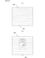
- "not parallel or perpendicular” refers to a state of being non-parallel and non-perpendicular, and means that it may be oblique to the width direction in the cross section of the protrusion. That is, for example, in FIGS. 11A to 11C, the reinforcing fibers constituting the unidirectional prepreg extend in the length direction (rib direction, paper depth direction) of the protrusion or in a direction perpendicular thereto.
- FIG. 11(A) shows a mode in which the reinforcing fibers 300 are parallel to the length direction (rib direction) of the protrusion 200
- FIG. 11C shows a mode in which the reinforcing fibers 300 are perpendicular to the direction (rib direction) and a mode in which the reinforcing fibers 300 are parallel and perpendicular to the length direction (rib direction) of the protrusion 200.
- the reinforcing fibers 300 are neither parallel nor perpendicular to the length direction (rib direction) of the protrusion 200 (that is, they are in a non-parallel and non-perpendicular state). It shows a state where the cross section is flat.
- the final fiber-reinforced plastic there is at least one layer formed by arranging unidirectional prepreg so that the orientation direction of the reinforcing fibers is neither parallel nor perpendicular to the length direction of the protrusion.
- the presence means that the reinforcing fibers extending over the longest direction of the protrusion are reduced. Therefore, dents 500 that occur along the fiber alignment direction in the protrusion of fiber reinforced plastic as shown in FIG. 11(A), and fibers and resin as shown in FIG. It is possible to suppress the occurrence of "unfilling" or so-called "resin richness", and at the same time, it is possible to improve the appearance quality.
- the protrusion becomes difficult to withstand the load in the shear direction. Therefore, the strength of the protrusion is insufficient, and cracks are likely to occur inside the protrusion along the fiber orientation direction, and the protrusion may break and peel off from the plate-like part.
- the fiber orientation direction is perpendicular to the length direction of the protrusion, it will be difficult for the reinforcing fibers to flow into the protrusion (the concave part of the mold) during molding, so the reinforcing fibers will not flow into the protrusion after molding. Unfilled areas may occur.
- the matrix resin is squeezed out from the unidirectional prepreg, and a region containing only resin (resin-rich) may be generated.
- At least one of the layers formed by arranging the unidirectional prepreg has a fiber orientation direction parallel to or parallel to the length direction of the at least one protrusion.
- a preferred embodiment is that it is not vertical.
- the angle between the fiber orientation direction and the length direction of the protrusion is not particularly limited within 0 to 90 degrees, as long as it is parallel or perpendicular. However, the angle is preferably 5 to 85 degrees. Further, from the viewpoint of filling properties into the protrusion and bonding strength between the protrusion and the plate-like part, the angle is more preferably 30 to 60°.
- the angular difference in the fiber orientation direction between the layers is not particularly limited, and all the layers may be aligned in the same direction or may be aligned in different directions. It can be freely selected depending on the desired properties of the composite. However, it is preferable to have layers in which the fiber orientation directions are not parallel to each other, since there are advantages such as the protrusion can withstand loads from multiple directions and the molded product (fiber-reinforced plastic) is less warped.
- the layer whose fiber orientation direction is neither parallel nor perpendicular to the length direction of the protrusion should be located close to the protrusion. It is preferable to laminate them in such a manner.
- the unidirectional prepreg is preferably arranged within the fourth layer from the side where the protrusion is located, and most preferably the unidirectional prepreg is arranged in the outermost layer of the side where the protrusion is located. It is preferable to do so.
- the two layers from the outermost layer on the side where the protrusion is located, and even the fourth layer from the outermost layer, are layers in which the fiber orientation direction is not parallel or perpendicular to the length direction of the protrusion.
- the number of unidirectional prepreg layers can be increased depending on the properties required of the fiber-reinforced plastic.
- the greater the number of laminated unidirectional prepregs the more fibers will flow into the protrusions, which is more preferable.
- the filling properties of the prepreg may differ for each protrusion, and it is possible that "unfilled” may easily occur in some protrusions.
- the fiber orientation direction of the unidirectional prepreg is neither parallel nor perpendicular to at least the length direction of the longest protrusion. More preferably, the fiber orientation direction of the unidirectional prepreg is neither parallel nor perpendicular to the length direction of all the protrusions. The same applies to the case where the protrusion extends in two different directions as described above.
- the reinforcing fibers have a fiber length of 10 to 300 mm.
- the reinforcing fibers can easily follow the shape of the protrusion of the molded product, improving the shapeability into a three-dimensional shape.
- disorder of fiber arrangement during shaping and molding is reduced, it is possible to obtain fiber-reinforced plastics with small variations in mechanical properties and high surface smoothness.
- the fiber length by setting the fiber length to 300 mm or less, the flexibility and fluidity of the reinforcing fibers are improved, and excellent shapeability and moldability can be obtained.
- the fiber length is set to 10 mm or more, the distance between the cuts increases, making it difficult for cracks that occur when a high load is applied to the fiber reinforced plastic to connect. becomes.
- the reinforcing fibers may move when the knife hits the reinforcing fibers, causing fibers to escape from the blade or get caught in the blade.
- the fiber length of the reinforcing fibers may be adjusted within the above-mentioned range by adjusting the fiber length of all the reinforcing fibers in the fiber-reinforced plastic. A sufficient effect can be obtained by adjusting only the fiber length.
- Examples of the unidirectional prepreg used in the present invention in which reinforcing fibers with a fiber length of 10 to 300 mm are arranged in one direction, include (1) discontinuous reinforcing fibers obtained by a spinning method such as tension spinning; (2) A reinforcing fiber sheet formed by arranging discontinuous reinforcing fibers (for example, chopped fibers) in one direction may be used. It may be impregnated with a matrix resin, or (3) the entire surface of a unidirectional prepreg composed of continuous reinforcing fibers may be impregnated with a matrix resin, for example, as shown in FIGS. It may also be an embodiment in which continuous or intermittent finite length incisions are made (incision prepreg).
- Stretch-cut spinning is a spinning method in which the fibers are cut in units of short fibers by applying tension to continuous fibers in the form of strands, and the cutting points of the short fibers are not concentrated in one place. It is characterized by being evenly distributed over the entire length of the strand.
- the cut ends of reinforcing fibers are arranged randomly so that they are not aligned in single fiber units to form an aggregate, and because the reinforcing fibers flow in single fiber units, the moldability is slightly inferior, but Since stress transmission is very efficient, it is possible to exhibit extremely high mechanical properties. Additionally, since the reinforcing fibers are cut at dispersed locations, it is possible to achieve excellent quality stability.
- the method (3) using a prepreg with incisions has excellent quality stability and mechanical properties because the reinforcing fibers are regularly arranged, and it also has excellent moldability because it flows in units of multiple fibers.
- the above three aspects (1), (2), and (3) can be selected as appropriate depending on the application, and all of them have excellent balance between mechanical properties and moldability, and can be easily manufactured.
- the method (3) in which continuous or intermittent finite length cuts are made in the direction across the reinforcing fibers on the entire surface of the unidirectional prepreg made of continuous reinforcing fibers is the most effective. preferable.
- the method of making cuts in the prepreg is not particularly limited.
- the method of mechanically making the incision is not particularly limited.
- a method of inserting cuts corresponding to the pulse period by scanning a pulse laser in a straight line at high speed can be exemplified. All of these methods are highly productive incision insertion methods, and you can choose one based on your own production equipment.
- the prepreg that has undergone such a process has a plurality of intermittent cuts in a direction that crosses at least some of the reinforcing fibers, and as a result, the fiber length of the reinforcing fibers in at least some of them becomes 10 to 300 mm. Then, substantially all of the reinforcing fibers are separated by the intermittent cuts, and shapeability and fluidity of the fibers during molding can be ensured.
- the length of the incision is preferably within the range of 30 ⁇ m to 1.5 mm when defined by the projected length Ws projected on a projection plane perpendicular to the reinforcing fibers in the plane of the prepreg base material.
- this cut may be longer where the base material extends, and may be shorter where the base material is crushed by compression. Therefore, when observing the fiber-reinforced plastic after molding, there are places where the cut length is not within the above range, but the final structure of the fiber-reinforced plastic is that reinforcing fibers with a fiber length of 10 to 300 mm are regularly arranged. By being present in , it is possible to obtain molded products with excellent mechanical properties and surface appearance.
- the projected length Ws projected on the projection plane in the direction perpendicular to the reinforcing fibers refers to the projected length Ws of the reinforcing fibers within the plane of the cut-inserted prepreg, as shown in Figures 2, 4, 5, and 6. Assuming that a projection plane exists in a direction perpendicular to the orientation direction (fiber perpendicular direction 6), it refers to the length when the incision is projected perpendicularly to the projection plane (fiber orientation direction 5).
- the absolute value of ⁇ is preferably within the range of 2 to 25°.
- the absolute value of ⁇ is 25° or less, mechanical properties, especially tensile strength, can be improved. From this point of view, it is more preferable that the absolute value of ⁇ is 15° or less.
- the absolute value of ⁇ is smaller than 2°, it may be difficult to stably make the depth of cut. That is, if the cut is too shallow with respect to the reinforcing fibers, the reinforcing fibers tend to escape from the blade when making the cut, and the positional accuracy of the cut decreases. From this point of view, it is more preferable that the absolute value of ⁇ is 5° or more.
- the method of inserting the cuts there are two methods: one is to insert the cuts continuously at the above-mentioned angle as shown in FIG. 3, and the other is to insert the cuts intermittently at multiple locations as shown in FIGS. Can be adopted.
- the fiber length can be controlled to be constant, and variations in mechanical properties and three-dimensional shape followability can be reduced.
- the prepreg is less likely to fall apart during lamination than continuous cuts, and is also easier to handle as a prepreg.
- a preferable cut pattern for the cut-inserted prepreg includes an embodiment in which a plurality of intermittent diagonal cuts 9 are provided in at least a portion of the prepreg base material in the direction across the reinforcing fibers, as shown in FIG. 4.
- a plurality of intermittent diagonal cuts 9 are inserted in a straight line to form rows 11, and further, a plurality of rows 11 are arranged parallel to each other.
- the distance X between the rows is preferably within a range of 1 to 5 mm, for example.
- Another preferable cut pattern for the cut-inserted prepreg includes an embodiment as shown in FIG. 5.
- at least a portion of the prepreg base material is provided with a plurality of intermittent diagonal cuts 9 in a direction across the reinforcing fibers, and the absolute value of ⁇ is substantially different from the diagonal cuts 9.
- Diagonal cuts 10 are provided which are identical (uniform) in terms of angle, but have opposite angles. Approximately half of these diagonal cuts 9 and 10 are provided.
- the absolute value of ⁇ is defined as “substantially the same” as an angle deviation within ⁇ 1°. Further, approximately half means that each of the diagonal cuts 9 and 10 is 45 to 55% when expressed as a percentage based on the total number of the diagonal cuts 9 and 10 (the same applies hereinafter).
- the depth of cut A preferable embodiment is one in which there are four or more incisions C having different positive and negative values of ⁇ and which are close to each other.
- the movement of the fiber end portion of the prepreg cut insertion portion is determined by the relationship between the cut angle and the fiber direction. Therefore, adjacent cuts have the same shape and angles in opposite directions, which ensures in-plane isotropy after molding when viewed macroscopically.
- a plurality of intermittent diagonal cuts 10 are provided in at least a portion of the cut-inserted prepreg in a direction across the reinforcing fibers.
- the intermittent diagonal cuts 10 are inserted linearly and with substantially the same length Y, and the shortest distance between adjacent cuts is longer than the length Y of the cuts.
- substantially the same length refers to a difference within ⁇ 5% (the same applies hereinafter).
- fiber-reinforced plastics break when cuts, which are discontinuous points in the fibers, are connected by cracks.
- a cut pattern in which the in-plane notches are separated from each other has the effect of suppressing crack connection at least in the same plane, and the strength is improved.
- the cut-inserted prepreg is provided with a plurality of intermittent cuts in the direction across the reinforcing fibers, and the intermittent cuts are straight and substantially straight.
- An example is one in which the distance between adjacent incisions on the same straight line is greater than three times the length Y of the incisions. If notches exist on the same straight line, damage caused by the notches may occur on the extension line of the notches, and in particular, the closer the distance between the notches, the more likely the cracks will connect. Therefore, by increasing the distance between the same straight cuts as much as possible, crack connection is suppressed and the strength is improved.
- all of the unidirectional prepregs may have fiber lengths adjusted within the above-mentioned range, but it is not necessary to arrange reinforcing fibers with such fiber lengths in all layers.
- the fiber length of at least a portion of the reinforcing fibers may be 10 to 300 mm, and the width and height of the protrusion of the fiber-reinforced plastic, Depending on the curvature and angle of the shape, the layer in which the unidirectional prepreg with adjusted fiber length is placed can be appropriately selected.
- the fiber weight (FAW) of at least the plate-shaped portion of the fiber-reinforced plastic of the present invention is, for example, 50 to 1,000 g/ m2 , but preferably 50 to 200 g/m2 from the viewpoint of deformation resistance and fluidity. 2 , more preferably 70 to 200 g/m 2 , most preferably 70 to 100 g/m 2 .
- the fiber weight of the plate-shaped part can be controlled mainly by adjusting the fiber weight of the unidirectional prepreg that constitutes it, but if the plate-shaped part is composed of two or more layers, at least one of the layers is preferably within the above range.
- the fiber area weight (FAW) is less than 50 g/m 2 , the cost increases due to an increase in the number of steps for producing the prepreg base material and for laminating. Further, from the viewpoint of reducing the number of lamination steps, it is more preferably 70 g/m 2 or more.
- a unidirectional prepreg (unidirectional layer) having a fiber basis weight of 70 g/m 2 or more and 100 g/m 2 or less on the outermost layer on the side of the protrusion.
- the unidirectional prepreg with the fiber basis weight is on the outermost layer on the side of the protrusion, the reinforcing fibers tend to follow the shape of the groove forming the protrusion of the mold, and there is an excessive amount of resin near the tip of the protrusion (“ "Resin Rich”) is less likely to occur.
- unidirectional prepregs When laminating two or more layers of unidirectional prepregs, it is also preferable to use unidirectional prepregs with two or more types of fiber weights. In other words, it is also preferable to have two or more types of unidirectional layers with different fiber weights inside the plate-like part.
- the layers may be laminated in any order, but for example, a unidirectional prepreg with a fiber basis weight smaller than that of at least one other unidirectional layer in the plate part is placed on the outermost layer on the side where the protrusion is located. It is preferable to arrange.
- a unidirectional prepreg with a high fiber basis that is difficult to flow is placed on the design surface side, and a unidirectional prepreg with a low fiber basis that is easy to flow (for example, 70 g/m 2 or more and 100 g/m 2 or less) is placed on the protrusion.
- a molded product with small fiber twisting and high protrusion filling properties can be obtained.
- the layer near the protrusions has a low fiber basis weight
- the middle layer has a high fiber basis weight, which improves the filling properties of the protrusions and reduces the number of lamination steps. It is also possible to achieve both.
- the resin mass fraction (Rc) of the molded article (fiber-reinforced plastic) of the present invention is preferably 10 to 70%. More preferably, it is 20 to 60%.
- the resin mass fraction (Rc) is less than 10%, the amount of resin on the surface of the molded product is small, and the surface of the molded product becomes uneven due to the unevenness of the fibers, and the fluidity of the fibers becomes low, resulting in "unfinished products" during molding. "filling” may occur.
- the resin mass fraction (Rc) exceeds 70%, the amount of resin increases, and areas with excess resin (“resin rich”) occur in the recesses of the molded product, and the surface of the molded product becomes smooth due to curing shrinkage of the resin. There may be a decrease in sexual performance.
- the fiber volume content (Vf) of the molded article of the present invention is preferably 43 to 58%.
- the proportion of resin is not excessive with respect to the reinforcing fibers, so that local resin richness is suppressed. If resin-rich exists, the molding shrinkage rate at the relevant location increases, which may cause dents on the surface, or may become a starting point for fracture when a load is applied to the molded product, resulting in a decrease in strength.
- the lower the proportion of reinforcing fibers and the higher the proportion of resin in the molded article the lower the strength, rigidity, and impact resistance of the molded article.
- the reinforcing fibers are not particularly limited, but glass fibers, aramid fibers, polyethylene fibers, silicon carbide fibers, and carbon fibers are preferably used.
- glass fibers and carbon fibers are preferably used because they are lightweight, high-performance, and provide fiber-reinforced composite materials with excellent mechanical properties.
- a single glass fiber may be used, a single carbon fiber may be used, and both glass fiber and carbon fiber may be used simultaneously from the viewpoint of a balance between performance and cost.
- the glass fibers are not particularly limited, but E glass fibers, S glass fibers, C glass fibers, and D glass fibers are preferably used. From the viewpoint of balance between cost and strength, E glass fiber is preferably used, S glass fiber is preferably used when high strength is required, and C glass fiber is preferably used when acid resistance is required. When a low dielectric constant is required, D glass fiber is preferably used.
- the average fiber diameter of the glass fibers is preferably 4 to 20 ⁇ m, more preferably 5 to 16 ⁇ m. Generally, if the fiber diameter is 4 ⁇ m or more, sufficient effects can be obtained, whereas if the average fiber diameter exceeds 20 ⁇ m, the strength tends to decrease.
- pre-treating glass fibers with coupling agents such as isocyanate compounds, organic silane compounds, organic titanate compounds, organic borane compounds, and epoxy compounds means that superior mechanical strength can be obtained. preferred.
- the carbon fibers are not particularly limited, but polyacrylonitrile carbon fibers, rayon carbon fibers, pitch carbon fibers, and the like are preferably used. Among these, polyacrylonitrile carbon fibers having high tensile strength are particularly preferably used. As the form of carbon fiber, twisted yarn, untwisted yarn, non-twisted yarn, etc. can be used.
- the tensile modulus of such carbon fibers is preferably in the range of 180 to 600 GPa. If the tensile modulus is within this range, the resulting fiber-reinforced plastic can have rigidity, so the weight of the molded product can be reduced. Generally, the strength of carbon fiber tends to decrease as the elastic modulus increases, but within this range, the strength of the carbon fiber itself can be maintained.
- a more preferable elastic modulus is in the range of 200 to 440 GPa, and even more preferably in the range of 220 to 300 GPa. The range may be a combination of any of the above upper and lower limits.
- the tensile modulus of carbon fiber is a value measured according to JIS R7608-2007.
- the number of carbon fiber filaments constituting the woven fabric is not particularly limited, but the number of filaments of carbon fibers constituting the woven fabric is not particularly limited. From the viewpoint of tensile/flexural modulus, strength, and design, the number of filaments is preferably 1,000 to 70,000, more preferably 1,000 to 60,000. Being a multifilament made by aligning many filaments, it has flexibility and can be easily deformed into any shape by molding. In addition, in multifilament, the defects of one fiber can be compensated for by other fibers, so variations in the mechanical properties of the molded product can be suppressed and stable performance can be obtained.
- thermosetting resin or a thermoplastic resin is preferably used as the main component of the matrix resin.
- thermosetting resin as the main component of the matrix resin may be a resin that self-cures with heat, or may contain a curing agent, a curing accelerator, etc., and may undergo a crosslinking reaction with heat. It is preferable to use a material that forms at least a partial three-dimensional crosslinked structure, but is not particularly limited.
- thermosetting resins include epoxy resin compositions, vinyl ester resin compositions, unsaturated polyester resin compositions, polyurethane resin compositions, benzoxazine resin compositions, phenolic resins, urea resin compositions, and melamine resins. Compositions, polyimide resin compositions, and the like are preferred from the viewpoint of ease of handling.
- thermosetting resin compositions containing these do not need to be of a single type, and may be mixed with each other, such as by mixing resin compositions with each other.
- the matrix resin may be prepared by dispersing the thermoplastic resin in the form of particles or fibers in the thermosetting resin, or blending the thermoplastic resin by dissolving the thermoplastic resin in the thermosetting resin.
- Thermoplastic resins used in this manner usually contain bonds selected from carbon-carbon bonds, amide bonds, imide bonds, ester bonds, ether bonds, carbonate bonds, urethane bonds, thioether bonds, sulfone bonds, and carbonyl bonds.
- bonds selected from carbon-carbon bonds, amide bonds, imide bonds, ester bonds, ether bonds, carbonate bonds, urethane bonds, thioether bonds, sulfone bonds, and carbonyl bonds.
- the thermoplastic resin has a crosslinked structure, it may have a partially crosslinked structure.
- thermoplastic resin as the main component of the matrix resin is not particularly limited, but from the viewpoint of easy processability, mechanical properties, and design, polymethylene methacrylate (PBSMMA) resin, polyurethane (TPU) resin, Polyethylene terephthalate (PET) resin, polybutylene terephthalate (PBT) resin, acrylonitrile butadiene styrene (ABS) resin, polyamide (PA) resin (especially PA6, PA66, PA12), polycarbonate (PC) resin, polycarbonate (PC) and acrylonitrile butadiene PC/ABS resin blended with styrene (ABS) resin is preferably used.
- PBSMMA polymethylene methacrylate
- TPU polyurethane
- PET Polyethylene terephthalate
- PBT polybutylene terephthalate
- ABS acrylonitrile butadiene styrene
- PA polyamide
- PC polycarbonate
- PC polycarbonate
- PC polycarbonate
- PC
- the colors are not particularly limited, but black, red, yellow, green, blue, purple,
- the design can be enhanced by adding a color such as brown.
- a non-unidirectional reinforced fiber sheet such as a woven fabric containing reinforcing fibers can be used in conjunction with the above-mentioned unidirectional prepreg.
- the reinforcing fibers constituting the non-unidirectional reinforcing fiber sheet those mentioned above can be used, but it is preferable that at least a portion thereof contains fibers other than thermoplastic resin fibers.
- press molding is performed by heating, but since thermoplastic resin fibers become soft with heat, at least some of the reinforcing fibers constituting the non-unidirectionally reinforced fiber sheet are made of thermoplastic resin.
- a woven fabric is preferably used as the form of the non-unidirectionally reinforced fiber sheet.
- a woven fabric is preferably used as the reinforcing fibers forming the outermost layer on the opposite side.
- Fabrics woven with warp and weft threads not only have excellent mechanical properties and form durability, but are also used to enhance design by showing the texture of the fabric. Note that the same reinforcing fibers as those for the other layers can be used as the fibers constituting this woven fabric, but it is also possible to use different fibers.
- the weave structure and density of the fabric are not particularly limited, and can be arbitrarily selected from the viewpoint of the design of the fiber-reinforced plastic.
- the weave structure plain weave, diagonal weave, satin weave, ridge weave, locust weave, nest weave, hack weave, patterned weave, and plain weave are preferably used.
- diagonal weaving we have three-ply diagonal, four-ply diagonal, five-ply diagonal, six-ply diagonal, extended diagonal, curved diagonal, broken diagonal, skipped diagonal, chevron diagonal, ajiro diagonal, and overlapped diagonal. Examples include oblique text, twisted oblique text, day/night oblique text, decorative oblique text, and blurred oblique text.
- Examples of satin weaves include 5-ply satin, 7-ply satin, 8-ply satin, 10-ply satin, irregular satin, widened satin, layered satin, makage weave, day and night satin, and blurred satin.
- Examples of ridge weaving include warp ridge weaving, horizontal ridge weaving, and variable ridge weaving.
- Examples of the Nanako weave include regular Nanako weave, modified Nanako weave, irregular Nanako weave, opposite Nanako weave, and triaxial fabric in which fibers are woven in three directions.
- the reinforcing fibers constituting the fabric may be a single glass fiber, a single carbon fiber, a combination of different glass fibers or carbon fibers, or other different reinforcing fibers, as exemplified above. It is also possible to use a single reinforcing fiber or a combination of a plurality of reinforcing fibers. Moreover, since it is excellent in performance, cost, and design, at least one type of glass fiber and at least one type of carbon fiber may be combined and woven.
- the fabric forming the outermost layer on the side opposite to the surface on which the protrusions are provided is impregnated with a matrix resin in advance.
- a matrix resin in advance, although it is preferable to use the same matrix resin as that for other layers as the matrix resin impregnated into the fabric, different resins can also be used. However, when using a resin different from the resins of other layers, it is preferable to check compatibility and adhesion, and insert an adhesive film or the like as necessary.
- the fiber weight of the fabric is preferably 10 to 300 g/m 2 , more preferably 30 to 150 g/m 2 .
- the fiber basis weight of the fabric is 10 g/m2 or more, it is possible to suppress the plastic flow of the fibers applied by the pressure generated during press molding, and the fiber meandering of the fabric fibers used in the surface layer and the resin-rich design surface can be suppressed. It is possible to suppress such poor appearance.
- the fiber basis weight of the fabric is 300 g/m2 or less, it is flexible and has excellent shapeability, and when impregnated with an epoxy resin composition during molding, the resin easily reaches the center in the thickness direction, and the unimpregnated area ( voids) are less likely to remain. The result is a fiber-reinforced plastic that exhibits excellent mechanical properties such as compressive strength.
- the basis weight of the prepreg obtained by impregnating a woven fabric with a matrix resin is preferably 20 to 400 g/m 2 , more preferably 40 to 300 g/m 2 when glass fiber or carbon fiber is used as the reinforcing fiber.
- the basis weight is 20g/ m2 or more, weaving properties are good, and when the basis weight is 400g/m2 or less , the fabric is flexible and easy to shape, and it is difficult to use matrix resin (e.g. epoxy resin) during prepreg production or molding.
- matrix resin e.g. epoxy resin
- the mesh thickness 107 of the fiber-reinforced plastic woven fabric 104 is 0.25 mm or less, as shown in FIG. 12.
- the thickness of the woven fabric refers to the thickness of each warp and weft in the woven state (not the thickness of the reinforcing fiber bundle itself before being woven), and the thickness of the warp and weft in the cross section of the warp and weft. This is the length in the thickness direction.
- woven fabrics in which warp and weft yarns are woven have crimps in the reinforcing fiber bundles, and the thicker the woven fabric, the larger the crimps.
- the larger the crimp the more likely a step 108 between the warp and weft will occur.
- the air contained in the prepreg before molding is pushed out as the resin flows by applying pressure during molding, but if the step between the warp and weft is large, the air will remain in the step and remain as air bubbles 109 on the surface of the molded product, causing the molding to fail.
- the appearance quality of the product may deteriorate.
- the mesh thickness of the fabric is 0.25 mm or less, the difference in level between the warp and weft does not become too large, and air bubbles are less likely to occur on the surface of the molded product, resulting in a good appearance.
- the weave thickness 107 of the fiber-reinforced plastic As a means for adjusting the weave thickness 107 of the fiber-reinforced plastic to 0.25 mm or less, for example, a method of molding using a prepreg having a thin weave thickness can be considered.
- the textile prepreg may also be drawn in as the resin and fibers of the unidirectional prepreg flow, causing the shape of the textile to change. be. Therefore, the mesh thickness of the fabric as a molded article is not uniformly determined by the mesh thickness of the fabric prepreg used.
- a unidirectional prepreg with inserted notches or a unidirectional prepreg with a low fiber basis weight of 100 g/m2 or less it is recommended to use a unidirectional prepreg with inserted notches or a unidirectional prepreg with a low fiber basis weight of 100 g/m2 or less , and to make the fiber direction of the unidirectional prepreg the same as the extension of the protrusion. It is also preferable to make the angle as low as possible with respect to the direction. By doing so, the filling property of the unidirectional prepreg into the protrusion increases, resin richness is less likely to occur at the base of the protrusion, and the shape of the weave of the fabric prepreg becomes difficult to move.
- a nonwoven fabric can also be preferably used as the form of the non-unidirectionally reinforced fiber sheet.
- the nonwoven fabric is preferably used, for example, inside a plate-like part where design is not required. Placing a nonwoven fabric inside can also improve the design of the surface of the molded product.
- the structure and manufacturing method of the nonwoven fabric are not particularly limited, but there is a card method in which short fibers of several centimeters are opened and a thin web is formed using a card machine, or a method in which the opened short fibers are dispersed in an air random machine and placed on a belt conveyor.
- a nonwoven fabric manufactured by a dry method such as an air-laid method to form a web can be preferably used.
- nonwoven fabrics manufactured using a dry method there are those whose fibers are intertwined using a needle punch method to improve the form stability of the web using a physical method, and those made of unsaturated polyester, polyvinyl alcohol (PVA), and their co-products.
- Fiber fixation methods include mixing thermoplastic resin fibers during web production, and attaching thermoplastic resin fine particles to the web, then placing the web in a heated roller or oven to melt the thermoplastic resin.
- An example of this method is to allow the fibers to adhere to each other.
- nonwoven fabric As another example of the nonwoven fabric, a nonwoven fabric produced by a wet method in which short fibers are dispersed in water and scooped onto a papermaking net can also be preferably used.
- a nonwoven fabric produced by a wet method in which short fibers are dispersed in water and scooped onto a papermaking net can also be preferably used.
- Binder resin can be applied by spraying or dipping to chemically fix the fibers to each other, thermoplastic resin fibers can be mixed during web production, or thermoplastic resin fine particles can be attached to the web and then heated using a hot roller. It is also preferable to put the web into an oven to melt the thermoplastic resin and fix the fibers to each other.
- Non-woven fabrics other than those mentioned above include the spunbond method, in which yarns obtained by melt-spinning thermoplastic resin are laminated on a belt conveyor, and the spunbond method, in which yarns obtained by melt-spinning thermoplastic resin are laminated on a belt conveyor, or the melt-spun yarns are blown with air to form fine fibers, and the fibers are placed on a net.
- Nonwoven fabrics produced by a melt-blown method in which they are aggregated to form a web can also be preferably used because they have excellent mechanical properties and are inexpensive.
- the basis weight of the nonwoven fabric is preferably 10 to 300 g/m 2 . Thickness and strength are necessary to absorb the deformation of the prepreg during molding and reduce the effect on the surface of the molded product, but if it becomes too thick, it may affect the physical properties of the molded product. , more preferably 30 to 150 g/m 2 , most preferably 40 to 100 g/m 2 . However, it is also possible to adjust the basis weight within the above range by layering nonwoven fabrics with low basis weights.
- the thickness thereof is preferably 0.01 to 1.0 mm, more preferably 0.05 mm to 0.5 mm.
- the thickness of the non-unidirectional reinforced fiber sheet is 0.01 mm or more, it is possible to suppress the plastic flow of the fibers applied by the pressure generated during press molding, and the meandering and Appearance defects such as resin-rich design can be suppressed.
- the thickness of the non-unidirectional reinforced fiber sheet is 1.0 mm or less, it is flexible and has excellent shapeability, and the resin easily reaches the center in the thickness direction when impregnated with an epoxy resin composition during molding. Unimpregnated areas (voids) are less likely to remain, resulting in a fiber-reinforced plastic that exhibits excellent mechanical properties such as compressive strength.
- the thickness of the non-woven fabric can be adjusted by the pressure during press molding, so a non-woven fabric with a thickness of 0.01 to 3.0 mm is preferable. .
- the fiber-reinforced plastic of the present invention can be produced by, for example, laminating a unidirectional prepreg in which a large number of reinforcing fibers are impregnated with a matrix resin with the same or different type of unidirectional prepreg or fiber base material as necessary.
- the bodies can be integrally obtained by press molding, autoclave molding, oven molding, or vacuum oven molding by heating and, if necessary, applying pressure.
- a unidirectional prepreg impregnated with matrix resin is prepared, laminated or shaped as necessary, and molded.
- a press molding method is used, in which the molded material is put into a container and heated and pressed using a press.
- press molding by molding under high pressure, the reinforcing fibers and matrix resin are integrated, and the effects of fiber slack and angle variations can be reduced.
- the cavity (gap) of the mold used in press molding has the final shape of the desired fiber-reinforced plastic, and the shape of the mold that corresponds to the protrusion of the fiber-reinforced plastic is a recess.
- press molding it is possible to mold the shape of fiber-reinforced plastic by flowing the reinforcing fibers and matrix resin into the recesses during heat molding, so it is not always necessary to mold the shape of the fiber-reinforced plastic in one direction in advance to the same shape as the fiber-reinforced plastic. There is no need to shape the prepreg. Therefore, the number of man-hours for producing the preform can be reduced, which is preferable.
- the press molding method is superior in productivity because preparations before molding and post-processing after molding are simpler. Furthermore, when the matrix resin is a thermosetting resin, it is possible to demold the mold while keeping the mold temperature T substantially constant. Therefore, since there is no need for a mold cooling process that is required when the matrix resin is a thermoplastic resin, high productivity can be obtained when combined with a fast-curing resin.
- the press molding mold temperature T (° C.) preferably satisfies the exothermic peak temperature Tp (° C.) of the thermosetting resin measured by differential scanning calorimetry (DSC) and the following relational expression (I). More preferably, the following relational expression (II) is satisfied.
- Tp-60 (°C) the time required for curing the resin becomes extremely long, and the curing may be insufficient.
- Tp+20 (° C.) a rapid reaction of the resin may result in the formation of voids inside the resin and poor curing.
- Tp (° C.) determined by DSC is a value measured at a temperature increase rate of 10° C./min.
- the fiber-reinforced plastic of the present invention is preferably produced under the condition that the thermosetting resin used as the matrix resin has a minimum viscosity of 0.1 to 100 Pa ⁇ s as determined by dynamic viscoelasticity measurement (DMA). More preferably, it is 0.5 to 10 Pa ⁇ s. If the minimum viscosity is less than 0.1 Pa ⁇ s, only the resin flows during pressurization, and the reinforcing fibers may not be sufficiently filled up to the tips of the protrusions. On the other hand, if it is greater than 100 Pa ⁇ s, the fluidity of the resin is poor, so the reinforcing fibers and resin may not be sufficiently filled up to the tips of the protrusions. Note that the minimum viscosity based on DMA is a value measured at a temperature increase rate of 1.5° C./min.
- a unidirectional prepreg in which a large number of reinforcing fibers are impregnated with a matrix resin is converted into a unidirectional prepreg of the same type or a different type, a non-unidirectional reinforcing fiber sheet, or other materials as needed.
- the preform is laminated with a fiber base material, etc., and the preform is placed in a preheated mold (for example, a concave mold), and the mold is closed and pressurized to form a plate-shaped part and a preform.
- a fiber-reinforced plastic having a shape having at least one protrusion raised from at least one surface of the plate-like part, but in this case, the fiber orientation direction of at least one layer of unidirectional prepreg in the preform is , it is preferable that the projections be neither parallel nor perpendicular to the length direction of the protrusion (non-parallel and non-perpendicular).
- the required number of unidirectional prepregs can be laminated according to the desired thickness of the fiber-reinforced plastic, but in this case, the fiber orientation direction of all the unidirectional prepregs is It is preferable that it is not parallel or perpendicular to the width direction (length direction) of the surface.
- the second and subsequent layers from the surface layer of the preform i.e., the protrusions
- a non-unidirectional reinforcing fiber sheet in a layer other than the outermost layer on the side where the reinforcing fiber sheet is provided.
- a non-unidirectionally reinforced fiber sheet in the form of a fabric is placed on the outermost layer on the opposite side to the surface on which the protrusions are provided, it is possible to suppress the plastic flow of the fibers caused by the pressurizing force during press molding. It is possible to suppress appearance defects such as fiber meandering of the textile fibers used in the surface layer and resin-rich design.
- the non-unidirectional reinforcing fiber sheet may be a dry sheet that does not contain a matrix resin, or a prepreg-like sheet in which at least a portion of the region is pre-impregnated with a matrix resin.
- the matrix resin that is pre-impregnated into the non-unidirectional fiber-reinforced sheet is preferably the same resin as the other prepregs, but any suitable resin can be selected from the viewpoints of adhesiveness and moldability. can be selected.
- the fiber volume content Vf[a] of the non-unidirectional reinforced fiber sheet and the fiber volume content Vf[b] of the unidirectional prepreg described above are equal to Vf[ It is preferable that the relationship is a]>Vf[b].
- the relationship is a]>Vf[b].
- the resin-unimpregnated portion of the non-unidirectional reinforced fiber sheet is impregnated with the resin contained in the unidirectional prepreg, thereby obtaining a molded product sufficiently filled with resin.
- Vf[a] is preferably 55 to 99.9%, more preferably 80 to 99%.
- Vf[a] is 55% or more, it is less affected by resin flow caused by pressure during press molding, and fiber flow can be suppressed, resulting in fiber reinforcement with excellent appearance quality with less fiber disorder and less surface unevenness. You can get plastic.
- a filler (Mikuni Paint Co., Ltd. Romen Filler Black 9-7606) was applied to the surface (design surface) opposite to the surface having the protrusions of the molded product. After sufficiently drying, the surface was polished with #400 sanding paper, and a primer (Origin Primer U-03, manufactured by Origin Co., Ltd.) was applied. Thereafter, a coating agent (Origin Planet HS Co., Ltd.) was applied twice with a spray gun.
- the molded product was rotated 360° in the horizontal direction and observed while tilted vertically at an angle of 0° to 60° to confirm whether there was any distortion in the reflected light from the fluorescent lamp along the ribs.
- "A” indicates that there is no distortion or dent at any angle without painting
- "B” indicates that there is distortion only at a certain angle before painting, but there is no distortion or dent at any angle after painting.
- a case where there is distortion only at a certain angle after painting but no dents is rated as "C”
- a case where there is distortion or dents at any angle after painting is rated as "D".
- the molded product is rotated 360° horizontally and then observed while tilted at an angle of 0° to 60° vertically. If there is no fading on the entire design surface at any angle, it is rated "A". Items with fading visible only at certain angles, but which can be hidden by painting, were rated ⁇ B'', and items with fading visible over the entire design surface, which could not be painted, were rated ⁇ C''.
- Bubble inspection on textile design surface The presence or absence of air bubbles was confirmed on the design surface of the molded product before painting. Specifically, hold the upper part of the plate in your hand with the protrusion facing down, and place it under fluorescent light (illuminance 1200 lx) on the side of the plate opposite to the side with the protrusion (textile design side). ) was visually observed before painting.
- the molded product was rotated 360° horizontally and observed while tilted vertically at an angle of 0° to 60°, and the number of bubbles that could be visually observed was counted. If the number of air bubbles is 3 or less on the entire surface of the textile design, it is rated "A", and if it is not, it is rated "B".
- ⁇ Measurement of thickness t of plate-shaped part The thickness of the plate-like parts on the left and right sides of the protrusion was measured using a micrometer, and the smaller one was taken as the thickness t of the plate-like part.
- a 100 mm x 100 mm concave mold was used as the lower mold, and a groove (rib groove, maximum width 1.5 mm, tip width 1
- a convex mold having a single-letter shape with a radius of curvature of 0.2 mm, a depth of 3 mm, and a length of 60 mm) was prepared as an upper mold and heated to 150°C.
- the prepreg base material laminate prepared in advance is placed in the lower mold with the 0° direction at the time of lamination parallel to the rib grooves, and the upper mold is attached to the lower mold, followed by hot press molding. Molding and heat curing of the matrix resin were performed using a machine under the conditions of a pressurizing force of 12 MPa, a heating temperature of 150° C., and a pressurizing time of 3 minutes to obtain a fiber-reinforced plastic having ribs.
- the obtained fiber-reinforced plastic had a single-character rib in the center of the 100 mm x 100 mm plate-like part, and when the appearance of the rib was observed, it was found that the tip of the rib was filled with carbon fibers.
- ⁇ Measurement of the maximum width w of the protrusion and the total thickness t' of the unidirectional layer (unidirectional layer located closer to the protrusion than the non-unidirectional layer) inside the plate-like part> ⁇ Thickness t of the plate-like part>
- the maximum width w of the protrusion was 1.5 mm, and the curved surface formed by the protrusion and the plate-shaped part was measured using the method described in
- the radius of curvature R was 0.2 mm
- the thickness t of the plate-like portion was 0.3 mm
- w/t was 5.
- Vf fiber volume content
- the obtained fiber-reinforced plastic had a single-character rib in the center of the 100 mm x 100 mm plate-like part, and when the appearance of the rib was observed, it was found that the tip of the rib was filled with carbon fibers.
- the maximum width w of the protrusion was 1.5 mm
- the radius of curvature R of the curved surface formed by the protrusion and the plate-like part was 0.2 mm
- the thickness t of the plate-like part was 0.3 mm. Yes, w/t was 5.
- Example 1 when inspected using the method described in ⁇ Appearance Quality: Inspection of Rib Lines on Designed Surface> above, there was no distortion in the reflected light of the fluorescent lamp at any angle without painting.
- Vf fiber volume content
- the resin-rich area was less than 3% of the total area of the protrusion and the plate-like part directly below the protrusion.
- Example 3 Eight sheets of prepreg base material each having a size of 100 mm x 100 mm were cut out from the cut-inserted prepreg into which cuts were inserted in the same manner as in Example 2, and they were laminated so that the stacking composition was [+45/-45] 4 . did.
- This prepreg base material laminate was press-molded under the same conditions as in Example 1 to obtain a fiber-reinforced plastic.
- the obtained fiber-reinforced plastic had a single-character rib in the center of the 100 mm x 100 mm plate-like part, and when the appearance of the rib was observed, it was found that the tip of the rib was filled with carbon fibers.
- the maximum width w of the protrusion was 2.0 mm
- the radius of curvature R of the curved surface formed by the protrusion and the plate-like part was 0.5 mm
- the thickness t of the plate-like part was 0.7 mm.
- w/t was 3.
- Example 1 when inspected using the method described in ⁇ Appearance Quality: Inspection of Rib Lines on Designed Surface> above, there was no distortion in the reflected light of the fluorescent lamp at any angle without painting.
- Vf fiber volume content
- Example 4 Six sheets of prepreg base material each having a size of 100 mm x 100 mm were cut out from the cut-inserted prepreg into which cuts were inserted in the same manner as in Example 2, and they were laminated so that the lamination configuration was [+45/-45] 3. did.
- This prepreg base material laminate was press-molded under the same conditions as in Example 1 to obtain a fiber-reinforced plastic.
- the obtained fiber-reinforced plastic had a single-character rib in the center of the 100 mm x 100 mm plate-like part, and when the appearance of the rib was observed, it was found that the tip of the rib was filled with carbon fibers.
- the maximum width w of the protrusion was 5.0 mm
- the radius of curvature R of the curved surface formed by the protrusion and the plate-like part was 1.0 mm
- the thickness t of the plate-like part was 0.5 mm. Yes, w/t was 10.
- Vf fiber volume content
- the prepreg with a fiber basis weight of 200 g/m 2 was placed on the lower mold side, and was molded using the same mold and conditions as in Example 4 to obtain a fiber-reinforced plastic.
- the obtained fiber-reinforced plastic had a single-character rib in the center of the 100 mm x 100 mm plate-like part, and when the appearance of the rib was observed, it was found that the tip of the rib was filled with carbon fibers.
- the maximum width w of the protrusion was 5.0 mm
- the radius of curvature R of the curved surface formed by the protrusion and the plate-like part was 1.0 mm
- the thickness t of the plate-like part was 0.5 mm. Yes, w/t was 10.
- Vf fiber volume content
- Example 6 Six sheets of prepreg base material each having a size of 100 mm x 100 mm were cut out from the cut-inserted prepreg into which cuts were inserted in the same manner as in Example 2, and they were laminated so that the lamination configuration was [+45/-45] 3.
- the obtained fiber-reinforced plastic had a single-character rib in the center of the 100 mm x 100 mm plate-like part, and when the appearance of the rib was observed, it was found that the tip of the rib was filled with carbon fibers.
- the maximum width w of the protrusion was 5.0 mm
- the radius of curvature R of the curved surface formed by the protrusion and the plate-like part was 1.0 mm
- the thickness t of the plate-like part was 0.5 mm.
- w/t was 10.
- the total thickness t' of the unidirectional layers located closer to the projection than the glass mat was 0.4 mm, and w/t' was 13.
- Vf fiber volume content
- Example 7 Nineteen sheets of prepreg base material each measuring 100 mm x 100 mm were cut out from the cut-inserted prepreg in which cuts were inserted in the same manner as in Example 2, and the laminated structure was [+45/-45] 9 [+45] Laminated like this.
- This prepreg base material laminate was press-molded under the same conditions as in Example 1 to obtain a fiber-reinforced plastic.
- the obtained fiber-reinforced plastic had a single-character rib in the center of the 100 mm x 100 mm plate-like part, and when the appearance of the rib was observed, it was found that the tip of the rib was filled with carbon fibers.
- the maximum width w of the protrusion was 8.0 mm
- the radius of curvature R of the curved surface formed by the protrusion and the plate-like part was 2.0 mm
- the thickness t of the plate-like part was 1.8 mm.
- w/t was 4.
- Vf fiber volume content
- Example 8 Four sheets of prepreg base material each having a size of 100 mm x 100 mm were cut out from the cut-inserted prepreg into which cuts were inserted in the same manner as in Example 2, and they were laminated so that the lamination configuration was [+45/-45] 2. did.
- This prepreg base material laminate was press-molded using the same mold and conditions as in Example 7 to obtain a fiber-reinforced plastic.
- the obtained fiber-reinforced plastic had a single-character rib in the center of the 100 mm x 100 mm plate-like part, and when the appearance of the rib was observed, it was found that the tip of the rib was filled with carbon fibers.
- the maximum width w of the protrusion was 8.0 mm
- the radius of curvature R of the curved surface formed by the protrusion and the plate-like part was 2.0 mm
- the thickness t of the plate-like part was 0.3 mm. Yes, w/t was 27.
- Vf fiber volume content
- Example 9 Eleven sheets of prepreg base material each having a size of 100 mm x 100 mm were cut out from the cut-inserted prepreg into which cuts were inserted in the same manner as in Example 2, and the laminated structure was [+45/-45] 5 [+45]. Laminated like this. A textile prepreg manufactured by Toray Industries, Inc. (#CO6343B, carbon fiber tensile strength 3,530 MPa, tensile modulus 230 GPa, basis weight 198 g/m 2 ) was placed at the bottom as a base material for the design surface, and the textile prepreg was placed on the lower mold side. This prepreg base material laminate was press-molded using the same mold and conditions as in Example 7 to obtain a fiber-reinforced plastic.
- Toray Industries, Inc. #CO6343B, carbon fiber tensile strength 3,530 MPa, tensile modulus 230 GPa, basis weight 198 g/m 2
- the obtained fiber-reinforced plastic had a single-character rib in the center of the 100 mm x 100 mm plate-like part, and when the appearance of the rib was observed, it was found that the tip of the rib was filled with carbon fibers.
- the maximum width w of the protrusion was 8.0 mm
- the radius of curvature R of the curved surface formed by the protrusion and the plate-like part was 2.0 mm
- the thickness t of the plate-like part was 1.2 mm.
- w/t was 7.
- the total thickness t' of the unidirectional layers located closer to the protrusion than the non-unidirectional layer was 1.0 mm
- w/t' was 8.
- Vf fiber volume content
- Example 10 Nine sheets of prepreg base material each having a size of 100 mm x 100 mm were cut out from the cut-inserted prepreg into which cuts were inserted in the same manner as in Example 2, and the laminated structure was [+45/-45] 4 [+45]. Laminated like this. This prepreg base material laminate was press-molded using the same mold and conditions as in Example 7 to obtain a fiber-reinforced plastic.
- the obtained fiber-reinforced plastic had a single-character rib in the center of the 100 mm x 100 mm plate-like part, and when the appearance of the rib was observed, it was found that the tip of the rib was filled with carbon fibers.
- the maximum width w of the protrusion was 8.0 mm
- the radius of curvature R of the curved surface formed by the protrusion and the plate-like part was 2.0 mm
- the thickness t of the plate-like part was 0.8 mm.
- w/t was 10.
- Vf fiber volume content
- Example 11 Nine sheets of prepreg base material each having a size of 100 mm x 100 mm were cut out from the cut-inserted prepreg into which cuts were inserted in the same manner as in Example 2, and the laminated structure was [+45/-45] 4 [+45]. Laminated like this. Example except that the rib groove for forming the protrusion (rib) used a single-letter-shaped upper mold with a maximum width of 9.0 mm, a tip width of 1.0 mm, a radius of curvature of 3.0 mm, a depth of 3 mm, and a length of 60 mm. This prepreg base material laminate was press-molded under the same conditions as in Example 1 to obtain a fiber-reinforced plastic.
- the obtained fiber-reinforced plastic had a single-character rib in the center of the 100 mm x 100 mm plate-like part, and when the appearance of the rib was observed, it was found that the tip of the rib was filled with carbon fibers.
- the maximum width w of the protrusion was 9.0 mm
- the radius of curvature R of the curved surface formed by the protrusion and the plate-like part was 3.0 mm
- the thickness t of the plate-like part was 0.8 mm.
- w/t was 11.
- Vf fiber volume content
- Example 12 Nineteen sheets of prepreg base material each measuring 100 mm x 100 mm were cut out from the cut-inserted prepreg in which cuts were inserted in the same manner as in Example 2, and the laminated structure was [+45/-45] 9 [+45] Laminated like this.
- This prepreg base material laminate was press-molded under the same conditions as in Example 1 to obtain a fiber-reinforced plastic.
- the obtained fiber-reinforced plastic had a single-character rib in the center of the 100 mm x 100 mm plate-like part, and when the appearance of the rib was observed, it was found that the tip of the rib was filled with carbon fibers.
- the maximum width w of the protrusion was 0.9 mm
- the radius of curvature R of the curved surface formed by the protrusion and the plate-like part was 0.2 mm
- the thickness t of the plate-like part was 1.8 mm. Yes, w/t was 0.5.
- Vf fiber volume content
- the prepreg with a fiber basis weight of 100 g/m 2 was placed on the lower mold side, and was molded using the same mold and conditions as in Example 2 to obtain a fiber-reinforced plastic.
- the obtained fiber-reinforced plastic had a single-character rib in the center of the 100 mm x 100 mm plate-like part, and when the appearance of the rib was observed, it was found that the tip of the rib was filled with carbon fibers.
- the maximum width w of the protrusion was 1.5 mm
- the radius of curvature R of the curved surface formed by the protrusion and the plate-like part was 0.2 mm
- the thickness t of the plate-like part was 0.3 mm. Yes, w/t was 5.
- Vf fiber volume content
- the area of resin richness was 5% or more of the total area of the protrusion and the plate-like portion directly below the protrusion.
- the obtained fiber-reinforced plastic had a single-character rib in the center of the 100 mm x 100 mm plate-like part, and when the appearance of the rib was observed, it was found that the tip of the rib was filled with carbon fibers.
- the maximum width w of the protrusion was 1.5 mm
- the radius of curvature R of the curved surface formed by the protrusion and the plate-like part was 0.2 mm
- the thickness t of the plate-like part was 0.3 mm. Yes, w/t was 5.
- ⁇ Appearance quality Inspection of rib stripes on designed surface>
- ⁇ Appearance quality Inspection of scratches on designed surface>
- ⁇ Measurement of fiber volume content (Vf)> ⁇ Inspection of resin richness in cross section of protrusions >In the ⁇ Appearance quality: Rib line inspection on the design surface>, there was no distortion in the reflected light of the fluorescent light at any angle without painting.
- ⁇ Appearance quality inspection of scratches on the designed surface>, no scratches were observed on the entire designed surface at any angle.
- Vf was 40%.
- ⁇ Inspection of resin richness of the cross section of the protrusion> revealed that the resin richness was 5% or more.
- This prepreg base material laminate was placed in the same mold as in Example 2 so that the 90° layer with the fiber orientation direction perpendicular to the rib groove was the second from the upper mold side, and was heated under the same conditions as in Example 2. It was molded to obtain fiber-reinforced plastic.
- the obtained fiber-reinforced plastic had a single-character rib in the center of the 100 mm x 100 mm x plate-like part, and when the appearance of the rib was observed, it was found that the tip of the rib was filled with carbon fibers.
- the maximum width w of the protrusion was 1.5 mm
- the radius of curvature R of the curved surface formed by the protrusion and the plate-like part was 0.2 mm
- the thickness t of the plate-like part was 0.3 mm. Yes, w/t was 5.
- Vf fiber volume content
- Example 17 Eleven sheets of prepreg base material each having a size of 100 mm x 100 mm were cut out from the cut-inserted prepreg into which cuts were inserted in the same manner as in Example 2, and the laminated structure was [+45/-45] 5 [+45]. Laminated like this. A textile prepreg manufactured by Toray Industries, Inc. (#CO6343B carbon fiber tensile strength 3,530 MPa, tensile modulus 230 GPa, basis weight 198 g/m 2 ) was placed at the bottom as a base material for the design surface, and the textile prepreg was placed on the lower mold side.
- the lower mold temperature was 150°C
- the upper mold temperature was 140°C
- the pre-heating time from placing the prepreg base material laminate in the mold to pressurizing it was 10 seconds.
- a fiber-reinforced plastic was obtained by press molding under the same conditions as in Example 1, except that the pressing force was 6 MPa.
- the obtained fiber-reinforced plastic had a single-character rib in the center of the 100 mm x 100 mm plate-like part, and when the appearance of the rib was observed, it was found that the tip of the rib was filled with carbon fibers.
- the maximum width w of the protrusion was 8.0 mm
- the radius of curvature R of the curved surface formed by the protrusion and the plate-like part was 2.0 mm
- the thickness t of the plate-like part was 1.2 mm.
- w/t was 7.
- the total thickness t' of the unidirectional layers located closer to the protrusion than the non-unidirectional layer was 1.0 mm
- w/t' was 8.
- Vf fiber volume content
- the obtained fiber-reinforced plastic had a single-character rib in the center of the 100 mm x 100 mm plate-like part, and when the appearance of the rib was observed, it was found that the tip of the rib was filled with carbon fibers.
- the maximum width w of the protrusion was 9.0 mm
- the radius of curvature R of the curved surface formed by the protrusion and the plate-like part was 2.0 mm
- the thickness t of the plate-like part was 0.3 mm. Yes, w/t was 30.
- Vf fiber volume content
- the obtained fiber-reinforced plastic had a single-character rib in the center of the 100 mm x 100 mm plate-like part, and when the appearance of the rib was observed, it was found that the tip of the rib was filled with carbon fibers.
- the maximum width w of the protrusion was 9.0 mm
- the radius of curvature R of the curved surface formed by the protrusion and the plate-like part was 2.0 mm
- the thickness t of the plate-like part was 0.3 mm.
- w/t was 30.
- the minimum total thickness t' of the unidirectional layers located closer to the protrusion than the non-unidirectional layer was 0.1 mm, and w/t' was 90.
- Vf fiber volume content
- the fiber-reinforced plastic of the present invention can be preferably used for members that require lightness as well as strength and rigidity, and for members that have a complex shape and require shape followability with other members.
- the above-mentioned requirements are strong, such as parts such as bicycle cranks and frames, sports parts such as golf club shafts and heads, structural parts such as doors, seats, members, modules, and frames of automobiles, and outer panels and interior materials.
- it can be preferably used for structural members and outer panels of medical equipment and information communication equipment.
Landscapes
- Engineering & Computer Science (AREA)
- Mechanical Engineering (AREA)
- Chemical & Material Sciences (AREA)
- Composite Materials (AREA)
- Moulding By Coating Moulds (AREA)
- Casting Or Compression Moulding Of Plastics Or The Like (AREA)
- Reinforced Plastic Materials (AREA)
Abstract
軽量で力学特性および外観品質に優れた、突起部を有する繊維強化プラスチックを提供することを目的とし、板状部と該板状部の少なくとも片側の面から隆起した突起部を少なくとも1箇所有する形状からなる繊維強化プラスチックにおいて、前記板状部の内部に、多数本の強化繊維がマトリックス樹脂中で一方向に配列された層(一方向層)を少なくとも1層有し、前記板状部の厚みtが0.3mm以上1.8mm以下であり、前記突起部の最大幅wと前記板状部の厚みtの比w/tが0.1以上27以下である繊維強化プラスチックとする。
Description
本発明は、板状部と該板状部の少なくとも片面から隆起した突起部とを有する形状からなる繊維強化プラスチックに関し、詳しくは、前記板状部および突起部が、多数本の強化繊維とマトリックス樹脂とで形成された繊維強化プラスチックに関する。
強化繊維とマトリックス樹脂とからなる繊維強化プラスチックは、比強度、比弾性率が高く、力学特性に優れること、耐候性、耐薬品性などの高機能特性を有することなどから、産業、スポーツ、医療、情報通信等の幅広い分野において活用が期待され、注目されている。
また、繊維強化プラスチックの力学特性向上や、力学特性を維持しながら、薄肉化と軽量化を促進することを目的に、成形品の断面形状を工夫し、肉厚変化やリブ形状を有する繊維強化プラスチックの設計が行われている。特にリブ形状は、成形品の広い平面部のソリなどを防ぐためにも有効であるが、形状が複雑となるため、成形性や量産性の点で課題がある。
高機能特性を有する繊維強化プラスチックの製造方法としては、オートクレーブ成形やプレス成形がある。オートクレーブ成形においては、プリプレグと称される、連続した強化繊維のシートや織物にマトリックス樹脂として熱硬化性樹脂を含浸せしめた半硬化状態のものを、積層し、高温高圧釜(オートクレーブ)で加熱加圧することにより熱硬化性樹脂のマトリックス樹脂を硬化させ、繊維強化プラスチックを成形する。プレス成形においては、上記のプリプレグを積層したものを、金型に投入し、プレス機で加熱加圧し、熱硬化性樹脂のマトリックス樹脂を硬化させて成形する、あるいは熱可塑性樹脂をマトリックス樹脂として含浸せしめたプリプレグを用い、当該熱可塑性樹脂を軟化、または溶融させ、成形した後、冷却脱型して成形する。特に熱硬化性樹脂を用いるプレス成形では、硬化速度が速い熱硬化性樹脂をマトリックス樹脂として、強化繊維に含浸させたプリプレグを使用することで、短時間で大量に成形品を生産できることから、生産性の高い成形方法として、近年注目されている。
上記のプリプレグを用いた成形方法において、肉厚が変化する形状やリブを有する形状など、複雑な形状の成形品を作る場合、所望の繊維強化プラスチックを板状部やリブ形状部などに細分化し、各部位を別々に成形した後、接着剤や熱融着により接合する方法が可能である。しかしながら、接着工程は手間とコストがかかる上に、接合部の強度や剛性がそれ以外の部分よりも低くなるため、先に接合部で壊れてしまい、繊維強化プラスチックの優れた力学特性や耐久性を十分に発揮することが難しかった。
一方、成形前に金型上で賦形し、プリフォームを作製してから成形する方法もある。この方法では、上記の接合部による破壊の問題は解決できるものの、賦形する工程に時間がかかるため、生産効率やコストが課題となっていた。
また、繊維強化プラスチックを用いて各種部材を作る場合、上記の成形性や量産性に加えて、外観品質が求められる場合があり、繊維強化プラスチックの持つ特有のヘアライン調、和紙調、織物模様などの外観は製品の付加価値を高める要素となる。しかし、肉厚が変化する形状やリブを有する形状では、成形時に強化繊維の流動が激しくなり、上記特有の外観が乱れるため、外観品質の達成が難しくなる。成形品の厚みを増やすことで、肉厚変化やリブ等の箇所に起因する強化繊維の流動の影響を小さくしたり、意匠面に外観品質の高い層を別途貼り付けたりする方法も考えられるが、軽量性や生産効率の観点で改善が望まれる。
このような従来技術の問題点を改善する試みが、提案されている(特許文献1、2)。
特許文献1には、切込を挿入して、繊維長が10~100mmになるように調整したプリプレグ基材を、少なくとも2枚以上積層し、プレス成形することで、リブ形状を成形する繊維強化プラスチックの製造方法が提案されている。かかる方法は、成型品の剛性とマテリアルバランスの観点では検討されているものの、外観品質への影響については検討されておらず、また厚物の部材の成型を対象としており、軽量化に課題がある。
特許文献2には、織物プリプレグと不連続繊維プリプレグの積層体からなる繊維強化プラスチックにおいて、各プリプレグの樹脂の発熱量がそれぞれ所定の条件を満たす場合に、織物の目乱れが少ない繊維強化プラスチックが得られることが示されている。この文献には、リブ成形時の外観品質についても記載されているが、リブの幅や板状部の厚みについては記載がなく、その補強効果や軽量性については明らかではない。
本発明は、従来技術の問題点を改善し、軽量で力学特性および外観品質に優れた、突起部を有する繊維強化プラスチックを提供することを目的とする。
かかる目的を達成する本発明は、次のいずれかの通りである。
(1)板状部と該板状部の少なくとも片側の面から隆起した突起部を少なくとも1箇所有する形状からなる繊維強化プラスチックにおいて、前記板状部の内部に、多数本の強化繊維がマトリックス樹脂中で一方向に配列された層(一方向層)を少なくとも1層有し、前記板状部の厚みtが0.3mm以上1.8mm以下であり、前記突起部の最大幅wと前記板状部の厚みtの比w/tが0.1以上27以下である繊維強化プラスチック。
(2)前記繊維強化プラスチックの繊維体積含有率(Vf)が43%~58%である、前記(1)に記載の繊維強化プラスチック。
(3)前記突起部の最大幅wと前記板状部の厚みtの比w/tが2以上27以下である、前記(1)または(2)に記載の繊維強化プラスチック。
(4)前記板状部の内部に前記一方向層を2層以上有し、前記突起部のある側の面から2層の前記一方向層は、繊維配向方向が突起部の長さ方向と非平行および非垂直である、前記(1)~(3)のいずれかに記載の繊維強化プラスチック。
(5)前記板状部の内部にある前記一方向層のうち、少なくとも一層の繊維目付が70g/m2以上100g/m2以下である、前記(1)~(4)のいずれかに記載の繊維強化プラスチック。
(6)前記板状部が強化繊維とマトリックス樹脂からなる層を複数層有し、前記板状部の片側の面のみに前記突起部を有し、その反対側の面の最表層を形成する前記強化繊維が織物である、前記(1)~(5)のいずれかに記載の繊維強化プラスチック。
(7)前記織物の目の厚みが0.25mm以下である、前記(6)に記載の繊維強化プラスチック。
(8)前記突起部と前記板状部とのなす曲面の曲率半径Rが2mm以下である、前記(1)~(7)のいずれかに記載の繊維強化プラスチック。
(9)前記突起部の最大幅wが8mm以下である、前記(1)~(8)のいずれかに記載の繊維強化プラスチック。
(10)前記板状部の内部に繊維目付の異なる2種類以上の前記一方向層を有している、前記(1)~(9)のいずれかに記載の繊維強化プラスチック。
(11)前記板状部における前記突起部のある側の最表層が前記一方向層であり、かつ当該最表層の一方向層の繊維目付が前記板状部中の他の少なくとも1層の一方向層の繊維目付より小さい、前記(10)に記載の繊維強化プラスチック。
(12)前記板状部が強化繊維とマトリックス樹脂からなる層を複数層有し、前記板状部の片側の面のみに前記突起部を有し、該突起部を有する面の最表層以外の層の少なくとも1層が、多数本の強化繊維がマトリックス樹脂中で少なくとも二方向に配向している層(非一方向層)である、前記(1)~(11)のいずれかに記載の繊維強化プラスチック。
(13)前記板状部が非一方向層を有し、前記突起部の最大幅wと前記非一方向層よりも前記突起部側に位置する一方向層の合計厚みt’の比w/t’が0.1以上27以下である、前記(1)~(12)のいずれかに記載の繊維強化プラスチック。
(14)前記板状部の内部にある前記一方向層のうち、少なくとも1層は、繊維長が10~300mmの強化繊維を含む、前記(1)~(13)のいずれかに記載の繊維強化プラスチック。
(15)一方向に配列した多数本の強化繊維にマトリックス樹脂を含浸させたプリプレグを少なくとも1層金型内に配置し、前記金型を閉じて加熱加圧することにより、前記(1)~(14)のいずれかに記載の繊維強化プラスチックを得る、繊維強化プラスチックの製造方法。
(16)前記(1)~(14)のいずれかに記載の繊維強化プラスチックを備えたゴルフクラブ。
本発明によれば、軽量で力学特性および外観品質に優れた、突起部を有する繊維強化プラスチックを提供することができる。
本発明の繊維強化プラスチックは、多数本の強化繊維がマトリックス樹脂中で一方向に配列された層(以下、一方向層と称することもある)を少なくとも1層有するものであり、例えば図1に示すように、板状部100と、該板状部100の少なくとも片側の面から隆起した突起部200を少なくとも1箇所有する形状からなる繊維強化プラスチックである。上述の通り、前記板状部100の内部には、一方向層が少なくとも1層ある。
ここで、突起部を板状部の面上方から見たときの突起部の形状を突起部の平面形状とし、該突起部の平面形状が延在する方向を突起部の延在する方向(以下、長さ方向と称することもある)とし、該平面形状において長さ方向に垂直な方向を突起部の幅方向とする。ここで平面形状が延在する方向とは平面形状が楕円形状である場合は長軸方向、長方形形状である場合は長辺の方向を指し、平面形状が上記以外の形状である場合は、その形状に外接する面積が最小の長方形の長辺の方向とする。また、突起部の長さ方向が最大になるような、突起部の長さ方向に平行で、かつ板状部の平面方向に垂直な断面を、突起部の横断面といい、突起部の幅方向が最大になるような、突起部の幅方向に平行で、かつ板状部の平面方向に垂直な断面を突起部の縦断面という。一例として、突起部の平面形状が図1のような楕円形である場合は、楕円の長軸方向が突起部の長さ方向20、短軸方向が突起部の幅方向21となり、該長軸に沿って板状部の平面方向に垂直な断面が突起部の横断面22、短軸に沿って板状部の平面方向に垂直な断面が突起部の縦断面23となる。
また、突起部が異なる二方向に延在するような場合、例えば平面形状が長方形あるいは楕円等の組合せで定義できる形状(X字形状、V字形状、H字形状またはY字形状等)には、突起部は複数の長さ方向を有すると解釈する。すなわち、突起部の平面形状がX字形状あるいはV字形状のときは2つの長さ方向、H字形状あるいはY字形状のときは3つの長さ方向を有すると解釈し、それに準じて上記平面形状を複数の形状に分解し、それぞれの方向に対応する複数の横断面、縦断面を有すると解釈する。
図7に板状部から隆起した突起部の縦断面図を示す。突起部200の幅は、図7のように先端と根元で異なっていてもよいし、同じでもよい。ただし先端に対して根元の幅が広い方が脱型の際に金型から取り出しやすく、また使用時に荷重がかかる際の応力集中を緩和できるため好ましい。また、図7のように突起部の先端と根元で形状が異なっているときは、根元における形状を突起部の平面形状とする。
突起部200と板状部100は曲面でつながっていることが好ましく、その曲率半径Rは2mm以下が好ましく、1mm以下がより好ましい。曲率半径Rが2mm以下であると突起部根元の体積が過剰に大きくならないため、後述するような一方向プリプレグが突起部に十分に充填される。そのため、樹脂比率の高い“樹脂リッチ”が生じづらくなり、意匠面側(突起部が一方の面にしか存在しない場合、突起部が存在する面とは反対側の面)のへこみや強化繊維の目ヨレの発生による外観品質の低下を抑制できる。曲率半径Rが小さすぎると、突起部200と板状部100との境界部分(以下、接合部または接点という)が鋭くなり強化繊維が触れて切断されたり、金型の加工が困難となることがあるため0.2mm程度は設けるのが好ましい。
本発明において、突起部の縦断面における最大の幅を突起部の最大幅wとする。すなわち、図7のような形状の場合は、板状部100と突起部200の接点の両端の間隔202を突起部の最大幅wとする。また、板状部と突起部が曲面でつながっている場合、最大幅はその曲面も含んだ間隔を指す。突起部の最大幅は8mm以下が好ましく、5mm以下がより好ましい。突起部の最大幅が突起部全域にわたって8mm以下であると、例えば板状部の厚みが1.8mm以下と薄くても外観品質の高い繊維強化プラスチックが得られるため、薄肉化・軽量化が達成できる。また、上述の通り突起部が異なる二方向に延在し、複数の縦断面を有する場合、最も最大幅が大きくなる縦断面における最大幅を、上記突起部の最大幅とする。
板状部100の形状は特に限定されないが、板状部の厚み101は0.3~1.8mmの範囲であり、かかる厚みは繊維とマトリックス樹脂の使用量を調整することで任意に設計できる。繊維とマトリックス樹脂の使用量を調整する方法としては、板状部を構成する繊維基材の積層数を調整する以外にも、マトリックス樹脂の量を変化させたり、繊維の種類を変えたりする等がある。
本発明の繊維強化プラスチックが、自動車やバイクなどの輸送機器、自転車やゴルフクラブなどのスポーツ器具、医療機器などに用いられる構造部材やカバー等の外板、その他の部品に使用される場合、要求される力学特性と軽量化の両立と実用性の観点から、板状部の厚みtは0.3~1.8mmである。さらに板状部に剛性と軽量化が特に求められる場合は、0.5~1.2mmが好ましい。特に、繊維強化プラスチックが厳しい軽量化が求められる部材、例えばゴルフクラブのヘッドに用いられる際、重量配置設計が飛距離や打感に大きな影響を与えるため、0.1g単位での設計が求められる場合がある。例えば、繊維目付100g/m2、樹脂質量分率(Rc)40%の、100mm×100mmのプリプレグからなる成形品の場合、板状部の厚みが0.1mm異なると重量は1~2g程度変化するため、重量への影響が大きい板状部の厚みの調整は非常に重要となる。板状部の厚みが1.8mmを超える場合、軽量化が必要な部材への適応が困難である。なお、本発明において板状部の厚みとは、縦断面における板状部100と突起部200の接点(板状部と突起部が曲面でつながっている場合、曲面と板状部の接点)における板状部の厚み101を指す。
本発明では突起部の最大幅w[mm]と板状部の厚みt[mm]の比w/tが0.1以上27以下である。上限としては、10以下が好ましく、5以下がより好ましい。w/tが27を超える場合、突起部に充填する強化繊維が足りずに意匠面にへこみが生じたり、突起部の根元に樹脂リッチが発生することで意匠面側の強化繊維が流動しやすくなり強化繊維のヨレ(目ヨレ)による外観品質の低下が生じたりする。図8に意匠面の模式図を示す。(A)は、強化繊維401が一方向にそろった目ヨレのない状態、(B)は、目ヨレ402のある状態を示しており、目ヨレの程度が大きいほど、外観品質が悪くなる。外観品質の観点ではw/tが小さいほどよいが、ある程度以下では外観品質の効果は飽和し、反対に突起部の補強効果は小さくなる。したがって、外観品質と、突起部への強化繊維の充填性や突起部の強度の観点からは、0.1以上が好ましく、2以上がより好ましく、3以上がさらに好ましい。w/tが2以上であると、良好な外観品質と成形品の強度向上の両立をより一層期待できる。また、例えば図7における板状部の厚み101が突起部の左右において異なる場合には、板状部の厚みが小さい方を板状部の厚みtとする。
外観品質の高い繊維強化プラスチックを得るためには、前述の定義に基づく縦断面だけではなく、該縦断面に平行な、突起部を含む断面の全てにおいて、突起部の幅に相当する長さと板状部の厚みに相当する長さの比が27以下を満たすことが好ましい。ただし、例えば一部で外観品質が必要なく、より幅の広い突起部を設けたい等の事情がある場合には、該縦断面以外の断面の一部にあえて上記の比が27を超える箇所を設けてもよい。
なお、突起部の最大幅や板状部の厚みの測定方法としては、突起部と板状部の接合部の両端の間隔をノギスやマイクロメーターで測ってもよいし、断面を顕微鏡で観察し、画像解析により算出してもよい。
本発明の繊維強化プラスチックの突起部の高さ203は、特に限定はされず、任意に設計できるが、0.1~50mmが好ましく、0.1~20mmであることがより好ましく、1~10mmがさらに好ましい。なお、板状部の厚み101が突起部の左右で異なる場合には、板状部の厚みが小さい方を基準として突起部の高さとする。突起部の高さが50mmを上回ると、後述する一方向プリプレグが突起部の先端まで充填しない未充填箇所が発生する可能性があり、0.1mmを下回ると、補強効果が小さくなり突起部を設ける意味が薄れる可能性がある。
そして、突起部の高さが1~6mmである場合、板状部を構成する繊維基材の、金型の突起部形成用の溝に流れ込む量が多くなりすぎず、繊維強化プラスチックの意匠面における繊維配向の乱れや表面の凹み等の発生をより確実に防ぐことができるため、最も好ましい。
本発明の繊維強化プラスチックは、板状部100の突起部を有する面の最表層以外の層の少なくとも1層が、非一方向層102であることが好ましい。さらには、図9のように、板状部100の突起部を設けた面とは反対側の最表層が非一方向層102であることが好ましい。
ここで、非一方向層とは、強化繊維が一方向のみに配列されているのではない状態の層をいい、すなわち、繊維の方向が少なくとも二方向に配向している層である。非一方向層のより具体的な態様としては、織物のように繊維が少なくとも二方向以上の決められた方向に配列されたものや、不織布のように繊維がランダムに配向されたものなどを例示でき、特に限定されるものでない。なお、本発明において、当該非一方向層とは繊維強化プラスチックにおける板状部を構成する層の1つを意味し、該繊維強化プラスチックを成形する前の、非一方向層に相当する材料を、非一方向強化繊維シートと称する。非一方向強化繊維シートは、前述のとおり強化繊維が一方向のみに配列されているのではなく、多方向に配列されているものであればいかなる形態であってもよく、マトリックス樹脂を含まない状態(ドライシート)でも、少なくとも一部の領域にあらかじめマトリックス樹脂を含浸させたものでもよい。
図9に示すように、板状部が非一方向層102を有する場合、板状部厚み101のうち、非一方向層よりも突起部側に位置する一方向層の合計厚み103をt’とすると、突起部の最大幅w[mm]と該一方向層の合計厚みt’[mm]の比w/t’は0.1以上27以下であることが好ましい。上限としては10以下がより好ましく、5以下が最も好ましい。w/t’が27を超える場合、突起部に充填する強化繊維シートが足りずに意匠面にへこみが生じる、あるいは突起部の根元に樹脂リッチが発生する等により、意匠面の強化繊維が流動しやすくなり繊維方向のズレが生じ外観品質が低下することがある。外観品質の観点ではw/t’が小さいほどよいが、突起部への強化繊維の充填性や突起部の強度の観点から0.1以上が好ましく、2以上がより好ましく、3以上がさらに好ましい。また、例えば図9における一方向層の合計厚み103が突起部の左右において異なる場合には、小さい方の合計厚みを合計厚みt’とする。
板状部から隆起した突起部の形状は、特に限定されず、目的に応じて種々の形態を採ることができる。例えば板状部の上面からみた形状が図1に示す楕円形の突起部のほか、多角形(例えば長方形)、円形、X字形状、V字形状、H字形状、I字形状、Y字形状、L字形状などの突起部を挙げることができる。また、これらを組み合わせてもよい。なお、図10(A)にX字形状、図10(B)にI字形状、図10(C)にH字形状の突起部を有する態様を示し、図10(D)にI字形状の突起部を複数有する態様を示す。
また突起部の横断面形状、縦断面形状としては、例えば、多角形(例えば長方形や三角形)、あるいは、半円形等がある。
突起部の断面形状や高さの寸法については、複数存在する突起部の全てを同じ形状・寸法とすることも可能であるが、繊維強化プラスチックの凸凹形状や曲率形状に合わせて、変化させることも可能であり、部分的に前記の形状にない箇所を作ることも可能である。
本発明の繊維強化プラスチックは、板状部の任意の場所に突起部を配置することができる。また、突起部の配置位置は、突起部の外観が全て確認できる繊維強化プラスチックの上面視において確認することができる。突起部の配置位置は、1箇所に限定されず、2箇所以上の場所に配置することが可能である。すなわち、同じ形状または異なる形状の突起部を2箇所以上の場所に設置することも可能である。
なお、突起部の箇所数は、上面視において、板状部が見える部分は突起部に該当しないと判断し、該板状部で囲まれる最小の突起部を独立した1つの突起部と認定して、数を数える。
突起部としてリブを設ける場合、本発明に係る繊維強化プラスチックの軽量化と剛性向上の両立を達成させるためには、リブを1箇所だけでなく、2箇所以上に配置することが好ましい。こうすることで、板状部の補強範囲を広げることができる。そして、2か所以上にリブを配置する場合、それらの長さ方向を互いに平行関係に配することで、補強効果を得ることができる。その場合、各リブが不連続、間欠的に設けられていてもよい。一方、複数のリブそれぞれの長さ方向が互いに平行関係でない場合(ハの字等)であっても、繊維強化プラスチックに要求される力学特性に合わせて、当該長さ方向をそれぞれ任意の方向となるように配置することが可能である。
リブの形状は、長さ方向が一方向だけの一文字形状だけでなく、少なくとも2方向のリブが任意の場所と角度で交差した十字形状(X字形状)やV字形状(複数の十字が連結した形状を含む)、さらには少なくとも3本のリブが1箇所で任意の角度で放射状に交差した形状など、繊維強化プラスチックに求められる力学特性により、任意に設計が可能である。
また、本発明の繊維強化プラスチックは、板状部の内部に、多数本の強化繊維がマトリックス樹脂中で一方向に配列された層(一方向層)を少なくとも1層有することを特徴とする。ここで、「板状部の内部」とは、板状部に相当する部分であればよく、表層を構成する部分であっても、それ以外の内層部分であってもよい。なお、本発明においては、繊維強化プラスチックを成形する前の、一方向層に相当する材料を一方向プリプレグと称する。
本発明の繊維強化プラスチックにおいては、例えばその前駆体となるプリフォームを作成する際、少なくとも一層の一方向プリプレグを、繊維配向方向が突起部の長さ方向と平行または垂直でないように、1層配置するのが好ましい。ここで、「平行または垂直でない」とは、非平行および非垂直である状態を言い、突起部の横断面における幅方向に対して斜めであればよいことを意味する。すなわち、例えば図11の(A)~(C)には、突起部の長さ方向(リブ方向、紙面奥行き方向)またはそれに直交する方向に、一方向プリプレグを構成する強化繊維が延在している態様を示しているが、このような態様とするのではなく、図11(D)のように、突起部の最も長い方向およびそれに直交する方向に亘って強化繊維が延在しないようにすることを意味する。なお、図11(A)は、強化繊維300が、突起部200の長さ方向(リブ方向)と平行である態様を、図11(B)は、強化繊維300が、突起部200の長さ方向(リブ方向)と垂直である態様を、さらに図11(C)は、強化繊維300が、突起部200の長さ方向(リブ方向)と平行および垂直である態様を示している。一方、図11(D)は、強化繊維300が、突起部200の長さ方向(リブ方向)と平行でも垂直でもない(すなわち非平行および非垂直の状態である)ため、その強化繊維300の断面が扁平となっている状態を表している。
最終的に得られる繊維強化プラスチックにおいて、突起部の長さ方向に対して、強化繊維の配向方向が平行にも垂直にもならないように、一方向プリプレグを配し形成した層が、少なくとも1層存在するということは、突起部の最も長い方向に亘って延在する強化繊維が低減されるということである。それゆえ、図11(A)に示すような繊維強化プラスチックの突起部において繊維の引き揃え方向に沿って発生する凹み500や、図11(B)、(C)に示すような繊維や樹脂の“未充填”の発生、いわゆる“樹脂リッチ”の発生を抑制でき、同時に外観品位の向上も図ることが可能となる。
繊維配向方向が突起部の長さ方向と平行である場合、突起部がせん断方向の荷重に耐えられにくくなる。そのため、突起部の強度が不足し、繊維配向方向に沿って突起部内部にクラックが入り易く、突起部が折れて、板状部から剥離する場合がある。また、繊維配向方向が突起部の長さ方向に対して垂直の場合は、成形時に強化繊維が突起部内部(金型の凹部分)に流動しにくくなるため、成形後の突起部内に強化繊維の未充填領域が発生する場合がある。また、強化繊維が流動しにくくなると、一方向プリプレグからマトリックス樹脂が搾り出され、部分的に樹脂のみの領域(樹脂リッチ)が発生する場合がある。
また、上述の通り突起部が異なる二方向に延在する場合、一方向プリプレグを配し形成した層の少なくとも一層は、繊維配向方向が、少なくとも一つの突起部の長さ方向に対して平行または垂直でないことが好ましい態様である。
なお、繊維配向方向と突起部の長さ方向の角度(強化繊維の配向方向と突起部の長さ方向の形成する角度)は、0~90°のうち、平行または垂直でなければ特に限定されないが、5~85°が好ましい。また、突起部への充填性や突起部と板状部の接合強度の観点から、更に好ましくは30~60°である。
一方向プリプレグを2層以上積層して板状部を構成する場合には、それぞれの繊維配向方向が突起部の長さ方向と平行でも垂直でもない層ができる限り多くなるように積層することが好ましい。その際、層間での繊維配向方向の角度差は特に限定されず、すべての層が同じ方向で引き揃えられていてもよいし、異なっていてもよい。所望するコンポジットの特性に応じて自由に選択できる。ただし、繊維配向方向が互いに平行でない層を有する場合の方が、突起部が多方向からの荷重に耐えられる、成形品(繊維強化プラスチック)の反りが小さくなる、等の利点があり好ましい。
強化繊維の配向方向が異なる複数の一方向プリプレグを積層する場合、一般的には[0/90]nSのような対称積層や、[0/±60]nS、[+45/0/-45/90]nSといった等方積層で、かつ、積層方向(厚み方向)に対しても対称積層構造とすることが、繊維強化プラスチックの板状部のソリ低減などに有効とされている。一方、本発明の繊維強化プラスチックでは、突起部をリブ形状にすることにより、反りを低減できるため、繊維の配向方向を繊維強化プラスチックに要求される剛性方向に偏重させることが可能である。
また、一方向プリプレグの積層順は任意に設定しても問題ないが、成形性の観点から、繊維配向方向が突起部の長さ方向と平行でも垂直でもない層を突起部に近い位置にするように積層することが好ましい。好ましくは、板状部において、突起部がある面から4層目以内に当該一方向プリプレグを配置することが好ましく、最も好ましくは突起部がある側の面の最表層に当該一方向プリプレグを配置するのが好ましい。また、突起部がある側の面の最表層から2層、さらには該最表層から4層目まで全てを、繊維配向方向が突起部の長さ方向と平行または垂直でない層とすることも好ましい。
さらに、一方向プリプレグの積層数は繊維強化プラスチックに要求される特性に応じて増やすこともできる。一方向プリプレグの積層数が多いほど突起部に流動する繊維が多くなるのでより好ましい。好ましくは4層以上であり、より好ましくは6層以上である。このように積層することにより、突起部に強化繊維が流動しやすく突起部末端にまで強化繊維を容易に充填できるようになるため、成形性や突起部の力学特性の観点から好ましい。
また、突起部が2つ以上ある場合は、それぞれの突起部に対してプリプレグの充填性が異なる場合があり、一部の突起部で“未充填”が発生しやすい場合が考えられる。その場合は、一方向プリプレグの繊維配向方向が、より充填しにくいと考えられる突起部の長さ方向に対して、平行にも垂直にもならないように、一方向プリプレグを積層することが好ましい。充填しにくい突起部の例を示すと、突起部の長さが長い程、プリプレグが充填しにくい。そのため、一方向プリプレグの繊維配向方向は、少なくとも最も長さが長い突起部の長さ方向に対して、平行でも垂直でもないことが好ましい。更に好ましくは、一方向プリプレグの繊維配向方向が、すべての突起部の長さ方向に平行でも垂直でもないことが好ましい。上述の通り突起部が異なる二方向に延在する場合も同様である。
本発明においては、強化繊維の少なくとも一部の繊維長を10~300mmにすることが好ましい。繊維長をこの範囲にすることで、強化繊維が成形品の突起部の形状に沿いやすくなり、三次元形状への賦形性が向上する。また、賦形や成形時の繊維配列の乱れが低減することから、力学特性のバラつきが小さく、表面平滑性が高い繊維強化プラスチックを得ることができる。
具体的には、繊維長を300mm以下とすることにより、強化繊維の柔軟性や流動性が向上し、優れた賦形性や成形性を得ることができる。一方、繊維長を10mm以上にすると、切込同士の距離が離れるため、繊維強化プラスチックに高い荷重が負荷された際に発生したクラックが連結し難いため、力学特性や耐久性が高い繊維強化プラスチックとなる。
なお、強化繊維を刃物で切断して繊維長を調整する場合、刃物が強化繊維に当たった際に強化繊維が動き、刃から逃げる繊維や刃に巻き込まれる繊維が発生する可能性があるため、繊維長が上記範囲にない繊維も存在することも考えられるが、大多数の強化繊維の繊維長を上記範囲に調整することで、十分な改善効果が期待される。また、成形時に金型のエッジなどが当たって切断される繊維も存在するため、成形品内部には上記範囲よりも短い繊維が存在する場合もある。
強化繊維の繊維長は、繊維強化プラスチック内の全ての強化繊維の繊維長を前述した範囲に調整してもよいが、突起部など繊維強化プラスチックの形状が変化する部分とその周辺の強化繊維の繊維長だけを調整しても十分な効果を得ることができる。
本発明において用いられる、繊維長10~300mmの強化繊維が一方向に配列された一方向プリプレグの態様としては、例えば、(1)牽切紡などの紡績手段によって得られる不連続状の強化繊維をシート化した強化繊維シートにマトリックス樹脂を含浸した態様であってもよいし、(2)不連続状の強化繊維(例えば、チョップドファイバー)を一方向に配列させてシート化した強化繊維シートにマトリックス樹脂を含浸した態様であってもよいし、あるいは、(3)連続状の強化繊維で構成される一方向プリプレグの全面に、例えば図2~図6に示すように、強化繊維を横切る方向に連続的もしくは断続的な有限長の切込を入れた態様(切込挿入プリプレグ)であってもよい。
(1)の牽切紡とは、ストランド状態の連続繊維に張力をかけることにより、繊維を短繊維の単位で切断する紡績方法の1つであり、短繊維の切断点が一箇所に集まらないで、ストランドの全長にわたって均等に分散するという特徴を有する。強化繊維の切断端を単繊維の単位で揃わないようにランダムに配置して集合体を形成するものであり、強化繊維が、単繊維の単位で流動するため、成形性に僅かに劣るが、応力伝達が非常に効率良くなされるため、極めて高い力学特性の発現を可能とする。また、強化繊維の切断箇所が分散しているため、優れた品質安定性の実現を可能とする。
(2)の、不連続状の強化繊維(例えば、チョップドファイバー)を一方向に配列させてシート化する方法は、強化繊維の切断端を複数の繊維の単位で揃えて、ある程度は規則正しく配置して集合体を形成するものである。必然的に強化繊維の配置、分布ムラなどを生じるため、品質安定性は僅かに劣るが、複数の繊維の単位で流動するため、極めて優れた成形性の実現を可能とする。
(3)の切込挿入プリプレグを用いる方法は、強化繊維が規則正しく配置しているため、品質安定性および力学特性に優れ、複数の繊維の単位で流動するため、成形性にも優れる。
上記の(1)、(2)、(3)の3つの態様は、用途に応じて適宜選択することができ、いずれも力学特性と成形性とのバランスに優れ、簡易に製造することができるものであるが、中でも(3)の、連続状の強化繊維で構成される一方向プリプレグの全面に、強化繊維を横切る方向に連続的または断続的な有限長の切込を入れる態様が、最も好ましい。
なお、プリプレグに切込を入れる方法は特に限定されない。例えば、カッターを用いての手作業により切込を入れる方法も可能であるが、品質が安定し、大量生産も可能な自動裁断機等を用いて機械的に切込を入れる方法が好ましい。機械的に切込を入れる方法としては、特に限定されない。例えば、テーブル上に広げたプリプレグ基材の上を刃が移動する裁断機で、所定の位置に切込を挿入する方法や、ミシン目の回転丸刃を一直線上に転がしたり、レーザー加工用のパルスレーザーを一直線上に高速で走査したりすることでパルス周期に対応する切込を挿入する方法などを例示することができる。いずれも生産性の高い切込挿入法であり、所有する生産設備などより、選択が可能である。
このような工程を経たプリプレグは、少なくとも一部の強化繊維を横切る方向へ断続的な切込が複数設けられ、その結果、少なくとも一部における強化繊維の繊維長が10~300mmとなる。そして、断続的な切込同士によって、実質的に強化繊維のすべてが分断されていることとなり、賦形性や成形時の繊維の流動性を確保できる。
切込の長さは、プリプレグ基材の面内における強化繊維に対して垂直方向の投影面に投影した投影長さWsで定義した場合、30μm~1.5mmの範囲内であることが好ましい。ただし、この切込は、賦形や成形時に基材が変形するため、基材が延びる場所では長くなり、基材が圧縮で潰される場所では短くなる可能性がある。そのため、成形後の繊維強化プラスチックで観察すると、切込の長さが上記範囲に無い箇所も存在するが、最終的に繊維長が10~300mmの強化繊維が規則正しく配置された構造が繊維強化プラスチックに存在することで、力学特性や表面外観に優れた成形品を得ることができる。
Wsを小さくすることにより、一つ一つの切込により分断される強化繊維の量が減り、強度向上が見込まれる。特に、Wsを1.5mm以下とすることで、大きな強度向上が見込まれる。一方で、Wsが30μmより小さい場合、切込位置の制御が難しく、強化繊維の繊維長のバラつきが大きくなり、所定範囲外の長さの強化繊維が増加し、賦形性や流動性が低下する場合がある。
ここで、「強化繊維に対して垂直方向の投影面に投影した投影長さWs」とは、図2、4、5、6に示すように、切込挿入プリプレグの面内において、強化繊維の配向方向に対して垂直な方向(繊維垂直方向6)に投影面が存在すると仮定して、切込を該投影面に垂直(繊維配向方向5)に投影した際の長さを指す。
プリプレグ基材の切込と強化繊維とのなす角度をθとしたとき、θの絶対値が2~25°の範囲内であることが好ましい。θの絶対値が25°以下であることで、力学特性、中でも引張強度を向上することができる。かかる観点からは、θの絶対値が15°以下であることがより好ましい。一方、θの絶対値は2°より小さいと、切込を安定して入れることが難しくなる場合がある。すなわち、強化繊維に対して切込が寝てくると、切込を入れる際、強化繊維が刃から逃げやすく、切込の位置精度が低下する。かかる観点からは、θの絶対値が5°以上であることがより好ましい。
切込を挿入する方法としては、図3に示すように例えば上記角度で連続的に挿入する方法と、図4~5に示すように断続的に切込を複数箇所に挿入する方法のいずれも採用できる。連続切込の場合は、繊維長さを一定にコントロールすることができ、力学特性、三次元形状追従性のバラツキを低減することができる。一方、断続的に切込を挿入する場合には、切込角度が強化繊維に対して斜めであることにより、実際の切込長さYの大きさに対して、プリプレグ基材の面内における強化繊維に対して垂直方向の投影面に投影した投影長さWsを小さくすることができる。そのため、例えばWs=1.5mm以下という極小の切込を工業的に安定して設けることができる。また積層時に連続切込よりもプリプレグがばらばらになり難く、プリプレグとしての取り扱い性にも優れる。
切込挿入プリプレグの好ましいカットパターンとしては、図4のように、プリプレグ基材の少なくとも一部に強化繊維を横切る方向へ断続的な斜め切込9が複数設けられた態様を挙げることができる。複数の断続的な斜め切込9が直線状に挿入されて列11を形成し、さらにその列11が複数かつ互いに平行に配置されていることが好ましい。このようにすることで、強化繊維が一定長のもと隣接する切込同士の距離を最大化することができ、その結果、繊維強化プラスチックを均質化しつつ強度を高めることができる。列間の距離Xは例えば1~5mmの範囲内であることが好ましい。
切込挿入プリプレグの別の好ましいカットパターンとしては、図5に示すような態様が挙げられる。この態様においては、プリプレグ基材の少なくとも一部に、強化繊維を横切る方向へ、複数の断続的な斜め切込9が設けられているとともに、該斜め切込9とはθの絶対値が実質的に同一(均一)であるものの、正負反対の角度となる斜め切込10が設けられている。これら斜め切込9、10は、略半数ずつ設けられている。ここでθの絶対値が「実質的に同一」の定義を、角度が、±1°以内のずれであることとする。また、略半数とは、斜め切込9、10の総数をベースとした百分率で示した時に、それぞれが45~55%であることをいう(以下同じ)。
また、図5に示すように、任意の1つの切込Aに着目したとき、該切込Aと近接する切込のうち、θの正負が同一である最も近い切込Bよりも切込Aとの最短距離が近い、θの正負が異なる切込Cが、4つ以上存在する実施態様が好ましい。三次元形状追従時にプリプレグの切込挿入部は、切込角度と繊維方向との関係で繊維端部の動きが決まる。そのため、近接する切込同士は同形状、逆方向の角度であることで、マクロに見た場合、成形後の面内の等方性が担保される。
切込挿入プリプレグを積層する際、斜め切込が一方向のみに存在する場合には、同一繊維方向のプリプレグであっても、プリプレグを表から見るか裏から見るかで異なる切込の方向となる。したがって、繊維強化プラスチック製造時に、毎回切込の方向が同じになるように制御する手間、もしくは同じ繊維方向で切込の方向が異なるものを同じ枚数積層するための積層手順を制御する手間が増える可能性がある。しかし、繊維方向からの切込の傾きの絶対値が同一であり、正の角度となる切込と負の角度となる切込とが略半数ずつとなるカットパターンであれば、通常の連続繊維プリプレグと同様の扱いで積層することが可能となる。
さらに、切込挿入プリプレグの好ましい実施態様として、図6に示すような態様も好ましい。この態様においては、切込挿入プリプレグの少なくとも一部に、強化繊維を横切る方向へ断続的な斜め切込10が複数設けられている。そして、その断続的な斜め切込10は、直線状かつ実質的に同一の長さYで挿入され、近接する切込同士の最短距離が該切込の長さYよりも長い。ここで実質的に同一の長さとは、±5%の差以内であることをいう(以下同じ)。力学特性の観点から、繊維の不連続点である切込同士がクラックにより連結された際、繊維強化プラスチックは破壊する。面内の切込同士の距離を離したカットパターンとすることで、少なくとも同一面内でのクラック連結を抑制する効果があり、強度が向上する。
さらに、切込挿入プリプレグの好ましい実施態様としては、切込挿入プリプレグの少なくとも一部に強化繊維を横切る方向へ断続的な切込が複数設けられており、断続的な切込が直線かつ実質的に同一の長さYで挿入され、かつ、同一直線上の近接する切込間の距離が、切込の長さYの3倍より大きいものが挙げられる。同一直線上に切込が存在する場合は、切込起因の損傷が切込の延長線上に発生する可能性があり、特に近接する距離が近いほどクラックが連結しやすい。従って同一直線状の切込同士の距離をできるだけ離すことでクラック連結が抑制され、強度が向上する。また、同一直線状に断続的な切込が挿入され、該切込同士の距離が近い場合は、成形後に切込が断続的な直線の模様として認識されやすくなる一方、切込同士の距離が離れていることで模様として認識されることがなくなり、表面品位に優れるものとなる。なお、同一直線上に切込が存在するとは、ある一つの切込を延長した直線と、前記切込と対象となる切込の互いに最も近接する点同士を結んだ直線との角度が、2°以内であることを指す。
また、一方向プリプレグの全てを繊維長が前述した範囲に調整されたものとしてもよいが、かかる繊維長の強化繊維を全ての層に配置する必要はない。繊維強化プラスチックの板状部を構成する一方向層のうち少なくとも1層において、強化繊維の少なくとも一部の繊維長が10~300mmであればよく、繊維強化プラスチックの突起部の幅や高さ、形状の曲率や角度により、繊維長を調整した一方向プリプレグを配置する層を適宜選択することができる。即ち、例えば繊維強化プラスチックの突起部における強化繊維と、板状部のうち突起部の直下の層における強化繊維の繊維長だけを調整しても十分な効果を得ることができる。
本発明の繊維強化プラスチックの少なくとも板状部の繊維目付(FAW)は、例として50~1,000g/m2が挙げられるが、変形抵抗や流動性の観点から、好ましくは50~200g/m2であり、更に好ましくは70~200g/m2、最も好ましくは70~100g/m2である。板状部の繊維目付は、主にそれを構成する一方向プリプレグの繊維目付を調整することで制御することができるが、板状部が2層以上で構成される場合は、その少なくとも1層が前記範囲であることが好ましい。
繊維目付(FAW)が高いほど繊維層の剛性が高くなり、1,000g/m2を超えると変形抵抗が大きくなり、繊維が突起部内部(金型凹部)に流動し難いため、“未充填”や“樹脂リッチ”が発生する場合がある。また、高目付のプリプレグ基材の繊維に刃物で切込を入れる際に、刃から逃げる繊維が増加し、目標範囲外の繊維長の繊維が増加し、流動性の低いプリプレグ基材になってしまう場合がある。そのため低目付のプリプレグ基材を多く積層した方が、成形性の観点からは好ましい。一方、繊維目付(FAW)が50g/m2未満の場合、プリプレグ基材の生産や積層工数の増加により、コストが高くなってしまう。また、積層工数削減の観点から、70g/m2以上がより好ましい。
そして、突起部側の最表層には、繊維目付が70g/m2以上100g/m2以下の一方向プリプレグ(一方向層)を配置するのがより好ましい。当該繊維目付の一方向プリプレグが突起部側の最表層にある場合、金型の突起部を形成する溝の形状に強化繊維が追従しやすく、突起部の先端付近に樹脂が過剰な部分(“樹脂リッチ”)が発生しづらくなる。
一方向プリプレグを2層以上積層する場合には、2種類以上の繊維目付の一方向プリプレグを使用するのも好ましい。言い換えると、板状部の内部に繊維目付の異なる2種類以上の一方向層を有する態様も好ましい。その際、任意の順序で積層してもよいが、例えば、突起部のある側の最表層に、板状部中の他の少なくとも1層の一方向層よりも繊維目付の小さい一方向プリプレグを配置することが好ましい。より具体的には、流動し難い高繊維目付の一方向プリプレグを意匠面側に配置し、流動しやすい低繊維目付(例えば70g/m2以上100g/m2以下)の一方向プリプレグを突起部側に配置して成型することで、繊維の目ヨレが小さく突起部充填性の高い成型品が得られる。また、突起部が板状部の両面にある場合には、突起部に近い層を低繊維目付とし、その中間層を高繊維目付とすることで、突起部の充填性と積層工数の削減の両立を図ることも可能である。
本発明の成形品(繊維強化プラスチック)の樹脂質量分率(Rc)は10~70%であることが好ましい。更に好ましくは、20~60%である。樹脂質量分率(Rc)が10%未満の場合、成形品表面の樹脂量が少ないため、繊維の凹凸により成形品表面が凸凹になる上に、繊維の流動性が低くなり、成形で“未充填”が発生する場合がある。一方、樹脂質量分率(Rc)が70%を超えると樹脂が多くなり、成形品の凹部などに樹脂が過剰な部分(“樹脂リッチ”)が生じ、樹脂の硬化収縮で成形品表面の平滑性が低下する場合がある。
本発明の成形品の繊維体積含有率(Vf)は43~58%であることが好ましい。繊維体積含有率(Vf)が43%以上の場合、樹脂の割合が強化繊維に対して過剰にならないため、局所的な樹脂リッチの発生が抑制される。樹脂リッチが存在すると、当該箇所の成形収縮率が大きくなるため表面に凹みが生じたり、成形品に荷重がかかった際に破壊の起点となり強度が低下する可能性がある。また、成形品中の強化繊維の割合が少なく樹脂の割合が多くなるほど、成形品の強度や剛性、耐衝撃性の低下につながる。一方、58%以下の場合、強化繊維を覆う樹脂量が確保されるため、成形品表面での強化繊維の露出が防げ、意匠面の凹凸や成形品表面での樹脂の染み出し不足である“カスレ”の発生が抑制できる。
本発明において、強化繊維は、特に限定されるものではないが、ガラス繊維、アラミド繊維、ポリエチレン繊維、炭化ケイ素繊維および炭素繊維が好ましく用いられる。特に軽量かつ高性能であり、優れた力学特性の繊維強化複合材料が得られる点で、ガラス繊維や炭素繊維が好ましく用いられる。また、ガラス繊維を単一で用いてもよいし、炭素繊維を単一で用いてもよく、性能とコストのバランスから、ガラス繊維と炭素繊維の両方を、同時に用いてもよい。
ここで、ガラス繊維は、特に限定されるものではないが、Eガラス繊維、Sガラス繊維、Cガラス繊維、Dガラス繊維が好ましく用いられる。コストと強度のバランスの観点からは、Eガラス繊維が好ましく用いられ、高強度を求められる場合にはSガラス繊維が好ましく用いられ、耐酸性を求められる場合にはCガラス繊維が好ましく用いられ、低誘電率を求められる場合にはDガラス繊維が好ましく用いられる。
ガラス繊維の平均繊維径に特に制限はないが、ガラス繊維の平均繊維径は4~20μmであることが好ましく、より好ましくは平均繊維径が、5~16μmである。通常4μm以上であれば十分効果を得ることができ、一方平均繊維径が20μmを超えると強度が低下する傾向にある。
また、ガラス繊維をイソシアネート系化合物、有機シラン系化合物、有機チタネート系化合物、有機ボラン系化合物およびエポキシ化合物などのカップリング剤で予備処理して使用することは、より優れた機械的強度を得る意味において好ましい。
炭素繊維は、特に限定されるものではないが、ポリアクリロニトリル系炭素繊維、レーヨン系炭素繊維、およびピッチ系炭素繊維等が好ましく用いられる。中でも、引張強度の高いポリアクリロニトリル系炭素繊維が、特に好ましく用いられる。炭素繊維の形態としては、有撚糸、解撚糸および無撚糸等を使用することができる。
かかる炭素繊維は、引張弾性率が180~600GPaの範囲であることが好ましい。引張弾性率がこの範囲であれば、得られる繊維強化プラスチックに剛性を持たせることができるため、得られる成形品を軽量化することができる。また一般に、炭素繊維は弾性率が高くなるほど強度が低下する傾向にあるが、この範囲であれば炭素繊維自体の強度を保つことができる。より好ましい弾性率は、200~440GPaの範囲であり、さらに好ましくは220~300GPaの範囲である。上記の上限と下限のいずれを組み合わせた範囲であってもよい。ここで、炭素繊維の引張弾性率は、JIS R7608-2007に従い測定された値である。
なお、炭素繊維の市販品としては、以下のものが挙げられるが、特にこれらに限定されるものではない。“トレカ(登録商標)”T300、“トレカ(登録商標)”T300B、“トレカ(登録商標)”T400HB、“トレカ(登録商標)”T700SC、“トレカ(登録商標)”T800HB、“トレカ(登録商標)”T800SC、“トレカ(登録商標)”T830HB、“トレカ(登録商標)”T1000GB-、“トレカ(登録商標)”T1100GC、“トレカ(登録商標)”M35JB、“トレカ(登録商標)”M40JB、“トレカ(登録商標)”M46JB、“トレカ(登録商標)”M55J、“トレカ(登録商標)”M60JB、“トレカ(登録商標)”M30SC(以上、東レ(株)製)、PX35(ZOLTEK社製)などを挙げることができる。
そして、本発明の繊維強化プラスチックに後述するような織物を用いる場合、該織物を構成する炭素繊維のフィラメント数としては、特に限定されるものではないが、製織生産性、要求される繊維強化プラスチックとしての引張・曲げ弾性率、強度、意匠性の観点から、1,000~70,000フィラメントの範囲であることが好ましく、さらには1,000~60,000フィラメントであることが好ましい。フィラメントを多数本引き揃えたマルチフィラメントであることで、柔軟性が得られ、成形で任意の形状に変形させ易い。また、マルチフィラメントは、一本の繊維の欠点を他の繊維が補うことができるため、成形品の力学特性のバラつきが抑えられ、安定した性能を得ることができる。
次に、本発明の繊維強化プラスチックを構成するマトリックス樹脂について説明する。マトリックス樹脂には、主成分として熱硬化性樹脂または熱可塑性樹脂が好ましく用いられる。
ここで、マトリックス樹脂の主成分としての熱硬化性樹脂は、熱により自己硬化する樹脂であってもよいし、硬化剤や硬化促進剤等を含むものであってもよく、熱により架橋反応を起こし少なくとも部分的な三次元架橋構造を形成するものが好ましいが、特に限定されるものではない。ここで熱硬化性樹脂の例としては、エポキシ樹脂組成物、ビニルエステル樹脂組成物、不飽和ポリエステル樹脂組成物、ポリウレタン樹脂組成物、ベンゾオキサジン樹脂組成物、フェノール樹脂、尿素樹脂組成物、メラミン樹脂組成物、およびポリイミド樹脂組成物等が、取り扱い性の観点から好ましい。中でもエポキシ樹脂組成物、ビニルエステル樹脂組成物、不飽和ポリエステル樹脂組成物は、繊維強化プラスチックの性能や耐環境性の観点から、より好ましい。また、これらを含む熱硬化性樹脂組成物は、単一の種類である必要は無く、樹脂組成物同士を混合するなど、相互に混合していてもよい。
さらに、熱硬化性樹脂に熱可塑性樹脂を粒子や繊維として分散、あるいは熱硬化性樹脂に熱可塑性樹脂を溶解させる等ブレンドして、マトリックス樹脂としてもよい。このようにして用いられる熱可塑性樹脂は、通常は、炭素-炭素結合、アミド結合、イミド結合、エステル結合、エーテル結合、カーボネート結合、ウレタン結合、チオエーテル結合、スルホン結合およびカルボニル結合より選択される結合を有する熱可塑性樹脂であることが好ましいが、部分的に架橋構造を有していても構わない。
一方、マトリックス樹脂の主成分としての熱可塑性樹脂は、特に限定されるものではないが、易加工性、力学特性、意匠性の観点から、ポリメチレンメタクリレート(PBSMMA)樹脂、ポリウレタン(TPU)樹脂、ポリエチレンテレフタレート(PET)樹脂、ポリブチレンテレフタレート(PBT)樹脂、アクリロニトリルブタジエンスチレン(ABS)樹脂、ポリアミド(PA)樹脂(特にPA6、PA66、PA12)、ポリカーボネート(PC)樹脂、ポリカーボネート(PC)とアクリロニトリルブタジエンスチレン(ABS)樹脂をブレンドした、PC/ABS樹脂が好ましく用いられる。
ここで、繊維強化プラスチックの意匠性の一つとして着色が求められる場合、特に色を限定するものではないが、前記に挙げた熱可塑性樹脂に、黒、赤、黄、緑、青、紫、茶などの着色をすることで、意匠性を高めることができる。
本発明においては、上述の一方向プリプレグと併せて、強化繊維を含む、織物などの非一方向強化繊維シートを用いることができる。
非一方向強化繊維シートを構成する強化繊維としては、上述のものを用いることができるが、少なくとも一部に熱可塑性樹脂繊維以外の繊維を含むことが好ましい。本発明の繊維強化プラスチックを製造する際、加熱してプレス成形を行うが、熱可塑性樹脂繊維は熱で柔らかくなるため、非一方向強化繊維シートを構成する強化繊維の少なくとも一部を熱可塑性樹脂繊維以外の繊維にすることで、成形品の厚みや形状のバラつきを抑制することができる。
非一方向強化繊維シートの形態としては、例えば織物が好ましく使用される。具体的には、本発明の繊維強化プラスチックが板状部の片側の面のみに突起部を有する場合、その反対側の最表層を形成する強化繊維として織物を配置することが好ましい。経糸と緯糸で織り込まれた織物は、力学特性や形態の耐久性に優れるだけでなく、織物の織目を見せることで意匠性を高めるために使用される。なお、この織物を構成する繊維には、その他の層と同じ強化繊維を使用することができるが、異なる繊維を使用することも可能である。
織物の織組織や密度は、特に限定されず、繊維強化プラスチック意匠性の観点から任意に選択することができる。織組織の例としては、平織り、斜文織り、朱子織り、うね織り、ななこ織り、はし巣織り、ハック織り、模しゃ織り、なし地織りが好ましく用いられる。斜文織りでは、3枚斜文、4枚斜文、5枚斜文、6枚斜文、伸び斜文、曲がり斜文、破れ斜文、飛び斜文、山形斜文、あじろ斜文、重ね斜文、よれ斜文、昼夜斜文、飾り斜文、ぼかし斜文を例示することができる。朱子織りでは、5枚朱子、7枚朱子、8枚朱子、10枚朱子、変則朱子、ひろげ朱子、重ね朱子、みかげ織り、昼夜朱子、ぼかし朱子を例示することができる。うね織りでは、たてうね織り、よこうね織り、変化うね織りを例示することができる。ななこ織りでは、正則ななこ織り、変化ななこ織り、不規則ななこ織り、向いななこ織り、3方向に繊維を織り込んだ3軸織物などを例示することができる。
織物を構成する強化繊維としては、上記に例示した、ガラス繊維単一でもよいし、炭素繊維単一でもよく、異なる複数のガラス繊維や炭素繊維を組み合わせて適用してもよく、さらにその他の異なる強化繊維を単一または複数組み合わせることも可能である。また、性能・コスト・意匠性に優れることから、少なくとも1種類のガラス繊維と少なくとも1種類の炭素繊維を合わせて交織してもよい。
また、突起部を設けた面とは反対側の最表層を形成する織物には、予めマトリックス樹脂が含浸されていることが好ましい。なお、織物に含浸するマトリックス樹脂は、その他の層と同じマトリックス樹脂を使用することが好ましいが、異なる樹脂も使用できる。ただし、その他の層の樹脂と異なる樹脂を使用する場合は、相溶性や密着性を確認し、必要に応じて接着フィルムなどを挿入することが好ましい。
織物の繊維目付としては、好ましくは10~300g/m2であり、より好ましくは30~150g/m2である。該織物の繊維目付が10g/m2以上の場合、プレス成形時に生じる加圧力によって付与される繊維の塑性流動を抑制することができ、表層に使用する織物繊維の繊維蛇行や意匠面の樹脂リッチといった外観不良を抑制することができる。また、該織物の繊維目付が300g/m2以下の場合、柔軟で賦形性に優れ成形時のエポキシ樹脂組成物などの含浸時に樹脂が厚み方向の中央部まで到達しやすく、未含浸部(ボイド)が残存しにくくなる。その結果、優れた圧縮強度等の機械物性を示す繊維強化プラスチックとなる。
また、織物にマトリックス樹脂を含浸したプリプレグとしての目付は、強化繊維としてガラス繊維や炭素繊維を用いる場合、好ましくは20~400g/m2であり、より好ましくは40~300g/m2である。目付が20g/m2以上の場合、製織性が良好となり、また、目付が400g/m2以下の場合、織物が柔軟で賦形しやすく、プリプレグ製造時や成形時のマトリックス樹脂(例えばエポキシ樹脂組成物など)の含浸時に、樹脂が厚み方向の中央部まで到達しやすく、未含浸部(ボイド)が残存しにくくなる。その結果、優れた圧縮強度等の機械物性を示す繊維強化プラスチックとなる。
また、突起部を設けた面とは反対側の最表層に織物を配置する場合、図12に示すように繊維強化プラスチックの織物104の目の厚み107が0.25mm以下であることが好ましい。ここで、織物の目の厚みとは、織り込まれた状態での経糸や緯糸それぞれの厚みであって(織り込まれる前の強化繊維束自体の厚みではない)、経糸や緯糸の横断面における板状部厚み方向の長さである。経糸と緯糸が織り込まれた織物は一方向プリプレグとは異なり強化繊維束にクリンプがあり、織物の目の厚みが大きいほど、クリンプも大きくなる。そして、クリンプが大きくなるほど、経糸と緯糸の段差108が生じやすくなる。成形前のプリプレグに含まれる空気は成形時に加圧することで樹脂の流動に伴い押し出されるが、経糸と緯糸の段差が大きい場合、空気が段差に留まり成形品表面に気泡109として残ってしまい、成形品の外観品位が悪化する場合がある。織物の目の厚みが0.25mm以下の場合、経糸と緯糸の段差が大きくなりすぎず、気泡が成形品表面に発生しにくくなり良好な外観が得られる。
繊維強化プラスチックにおける織物の目の厚み107を0.25mm以下に調整する手段として、例えば、織物の目の厚みが薄いプリプレグを用いて成形する方法が考えられる。しかし、成形時に一方向プリプレグが金型の突起部形成用の溝に流れ込む際、その一方向プリプレグの樹脂や繊維の流動に伴い織物プリプレグも引き込まれて、織物の目の形状が変化する場合がある。そのため、成形品としての織物の目の厚みは使用する織物プリプレグの目の厚みによって一様に決まるわけではない。そこで、例えば材料面では、切込の挿入された一方向プリプレグや繊維目付が100g/m2以下の低目付の一方向プリプレグを用いること、また、一方向プリプレグの繊維方向を突起部の延在方向に対してできるだけ低角度にすることなども好ましい。このようにすることで、突起部への一方向プリプレグの充填性が高まり、突起部根元で樹脂リッチが発生しづらくなり、織物プリプレグの目の形状が動きにくくなる。また、成形条件面では、加圧のタイミングでのプリプレグの樹脂粘度を最適化するために、加熱した金型にプリプレグを配置して加圧するまでの余熱時間を設けることも好ましい。さらに、織物の目は動きづらく、一方向プリプレグは突起部の溝に充填しやすくなるように、意匠面側と突起部側の金型に温度差をつけて成形することも好ましい。
また、非一方向強化繊維シートの形態としては、不織布を好ましく使用することもできる。不織布は、たとえば意匠性が必要とされない板状部の内部に用いることが好ましい。内部に不織布を配置することでも、結果的に成形品表面の意匠性を向上することができる。
不織布の構造や製造方法は特に限定されないが、数cmの短繊維を開繊し、カード機で薄いウェブを形成するカード法や、開繊した短繊維をエアランダム機で分散させ、ベルトコンベア上にウェブを形成するエアレイド法、などの乾式法で製造された不織布を好ましく使用することができる。また、乾式法で製造された不織布の場合、ニードルパンチ法で繊維を絡め、物理的な方法でウェブの形態安定性を向上させたものや、不飽和ポリエステルやポリビニールアルコール(PVA)やその共重合体などのバインダー樹脂をスプレー法やディッピング法で付与して繊維同士を固着し、化学的にウェブの形態安定性を向上させたものが好ましく使用できる。繊維の固着方法としては、ウェブの製造時に熱可塑性樹脂の繊維を混繊する方法、熱可塑性樹脂微粒子をウェブに付着させた後、熱ローラーやオーブンにウェブを投入して、熱可塑性樹脂を溶融させ、繊維同士を固着させる方法を挙げることができる。
不織布の他の例としては、短繊維を水中に分散し、抄紙ネット上にすくい上げる湿式法で製造された不織布も好ましく使用できる。なお、湿式法で製造された不織布を、乾式法で製造された不織布と同様に寸法安定性や取り扱い性を向上させるために、不飽和ポリエステルやポリビニールアルコール(PVA)やその共重合体などのバインダー樹脂をスプレー法やディッピング法で付与して繊維同士を化学的に固着させたり、ウェブ製造時に熱可塑性樹脂の繊維を混繊したり、熱可塑性樹脂微粒子をウェブに付着させた後、熱ローラーやオーブンにウェブを投入して、熱可塑性樹脂を溶融させて、繊維同士を固着させることも好ましい。
上記以外の不織布としては、熱可塑性樹脂を溶融紡糸して得た糸をベルトコンベア上に積層するスパンボンド法や、溶融紡糸した糸に空気を吹き付けて微細な繊維とし、その繊維をネット上に集積して、ウェブ化するメルトブローン法で製造した不織布も、力学特性に優れ、安価であることから、好ましく使用することができる。
不織布の目付は、10~300g/m2が好ましい。成形時のプリプレグの変形を吸収し、成形品表面への影響を緩和するためには、厚みと強度が必要であるが、厚くなりすぎると、成形品の物性に影響する可能性があることから、より好ましくは、30~150g/m2であり、もっとも好ましくは40~100g/m2である。ただし、低目付の不織布を重ねることにより、前記目付の範囲に調整することも可能である。
また、非一方向強化繊維シートは、板状部の表層に設ける場合、その厚みが0.01~1.0mmであることが好ましく、0.05mm~0.5mmであることがより好ましい。非一方向強化繊維シートの厚みが0.01mm以上の場合、プレス成形時に生じる加圧力によって付与される繊維の塑性流動を抑制することができ、板状部の表層に使用する織物繊維の蛇行や意匠面における樹脂リッチといった外観不良を抑制することができる。一方、非一方向強化繊維シートの厚みが1.0mm以下の場合、柔軟で賦形性に優れるとともに、成形時のエポキシ樹脂組成物などの含浸時に樹脂が厚み方向の中央部まで到達しやすく、未含浸部(ボイド)が残存しにくくなり、その結果、優れた圧縮強度等の機械物性を示す繊維強化プラスチックとなる。
ただし、非一方向強化繊維シートとして不織布を用いる場合は、プレス成形時の圧力で該不織布の厚みを調整することが可能であるため、0.01~3.0mm厚みの不織布であることが好ましい。
次に、本発明に係る繊維強化プラスチックの製造方法について一例を詳細に説明するが、これによって本発明は限定されるものではない。
本発明の繊維強化プラスチックは、例えば、多数本の強化繊維にマトリックス樹脂を含浸させた一方向プリプレグを、必要に応じて同種または異なる種類の一方向プリプレグや繊維基材などと積層し、その積層体を、プレス成形、オートクレーブ成形、オーブン成形、または真空引きオーブン成形により加熱および必要に応じて加圧することで一体化して、得ることができる。
成形方法としては、上記したように種々の成形方法を挙げることができ、特に限定されないが、マトリックス樹脂を含浸させた一方向プリプレグを準備し、必要に応じて積層や賦形を行い、金型に投入し、プレス機で加熱加圧して成形するプレス成形法が好ましく使用できる。プレス成形では、高圧力で成形することで、強化繊維とマトリックス樹脂が一体化し、繊維の弛みや角度のバラつきの影響を小さくすることができる。
プレス成形で使用する金型のキャビティー(間隙)は最終的に所望する繊維強化プラスチックの形状をしており、繊維強化プラスチックの突起部に当たる金型の形状は凹部になっている。プレス成形では、加熱成形する際に、強化繊維とマトリックス樹脂をその凹部に流動させ繊維強化プラチックの形状を成形することが可能であることから、必ずしも事前に繊維強化プラスチックと同一の形状に一方向プリプレグを賦形する必要がない。そのため、プリフォーム製作の工数を低減することができ、好ましい。
プレス成形方法は、他の成形方法に比べ、成形前の下準備、更には、成形後の後処理も簡便なため、生産性に優れる。更に、マトリックス樹脂が熱硬化性樹脂である場合は、金型温度Tを実質的に一定に保ったまま脱型することが可能である。従って、マトリックス樹脂が熱可塑性樹脂の場合に必要となる金型の冷却工程が不要であることから、速硬化樹脂と組み合わせれば、高い生産性を得ることができる。
なお、プレス成形の金型温度T(℃)は、熱硬化性樹脂の示差走査熱量測定(DSC)による発熱ピーク温度Tp(℃)と、次の関係式(I)を満たすことが好ましい。より好ましくは、次の関係式(II)を満たすことが、好ましい。
Tp-60≦T≦Tp+20 ・・・(I)
Tp-30≦T≦Tp ・・・(II)
金型温度T(℃)が、Tp-60(℃)より低い場合、樹脂の硬化に要する時間が非常に長くなり、また、硬化が不十分である場合がある。一方、Tp+20(℃)より高い場合、樹脂の急激な反応により、樹脂内部でのボイドの生成、硬化不良を引き起こす場合がある。なお、DSCに拠る発熱ピーク温度Tp(℃)は、昇温速度10℃/分の条件にて測定した値である。
Tp-30≦T≦Tp ・・・(II)
金型温度T(℃)が、Tp-60(℃)より低い場合、樹脂の硬化に要する時間が非常に長くなり、また、硬化が不十分である場合がある。一方、Tp+20(℃)より高い場合、樹脂の急激な反応により、樹脂内部でのボイドの生成、硬化不良を引き起こす場合がある。なお、DSCに拠る発熱ピーク温度Tp(℃)は、昇温速度10℃/分の条件にて測定した値である。
本発明の繊維強化プラスチックは、マトリックス樹脂として用いる熱硬化性樹脂の動的粘弾性測定(DMA)に拠る最低粘度が0.1~100Pa・sの条件で製造されることが好ましい。より好ましくは、0.5~10Pa・sである。最低粘度が0.1Pa・sより小さい場合、加圧時に樹脂のみが流動し、突起部の先端まで十分に強化繊維が充填されない場合がある。一方、100Pa・sより大きい場合、樹脂の流動性が乏しいため、突起部の先端まで十分に強化繊維および樹脂が充填されない場合がある。なお、DMAに拠る最低粘度は、昇温速度1.5℃/分の条件にて測定した値である。
また、本発明においては、まず、多数本の強化繊維にマトリックス樹脂を含浸させた一方向プリプレグを、必要に応じて、同種もしくは異なる種類の一方向プリプレグや、非一方向強化繊維シート、または他の繊維基材などと共に積層してプリフォームとし、そのプリフォームを、予め加熱した金型内(例えば凹型金型)に配置し、該金型を閉じて加圧することにより、板状部と該板状部の少なくとも片側の面から隆起した突起部を少なくとも1箇所有する形状からなる繊維強化プラスチックを得ることが好ましいが、このとき、プリフォーム中の少なくとも1層の一方向プリプレグの繊維配向方向が、突起部の長さ方向と平行でも垂直でもないようにする(非平行および非垂直となるようにする)ことが好ましい。
なお、本発明においては、所望する繊維強化プラスチックの厚さに応じて一方向プリプレグを必要な枚数積層することができるが、その際、全ての一方向プリプレグの繊維配向方向を、突起部の横断面における幅方向(長さ方向)と平行または垂直でないようにすることが好ましい。
また、上記したように、一方向プリプレグを、他の一方向プリプレグ、非一方向強化繊維シート、または繊維基材などと組み合わせる場合、プリフォームの表層から2層目以降の層(すなわち、突起部が設けられる側の最表層以外の層)に、非一方向強化繊維シートを配置することも好ましい。特に、突起部を設けた面とは反対側の最表層に織物形態の非一方向強化繊維シートを配置した場合には、プレス成形時の加圧力によって生じる繊維の塑性流動を抑制することができ、表層に使用する織物繊維の繊維蛇行や意匠面の樹脂リッチといった外観不良を抑制することができる。
非一方向強化繊維シートは、マトリックス樹脂を含まないドライシートであっても、少なくとも一部の領域にあらかじめマトリックス樹脂を含浸させたプリプレグ状のシートであってもよい。
非一方向繊維強化シートがプリプレグ状のシートの場合、該非一方向強化繊維シートに予め含浸するマトリックス樹脂は、他のプリプレグと同じ樹脂が好ましいが、接着性や成形性の観点から好ましいものを任意に選択することができる。
また、非一方向繊維強化シートがプリプレグ状のシートの場合、非一方向強化繊維シートの繊維体積含有率Vf〔a〕と前述の一方向プリプレグの繊維体積含有率Vf〔b〕は、Vf〔a〕>Vf〔b〕の関係であることが好ましい。この場合、プレス成形時に一方向プリプレグに含まれるマトリックス樹脂を非一方向強化繊維シートに含浸させる余地が生じる。すなわち、プレス成形時の圧力によって、非一方向強化繊維シートの樹脂未含浸部分に一方向プリプレグに含有されていた樹脂が含浸されることになり、樹脂が十分に充填された成形品を得ることができ、例えばボイド率が2%以下の力学特性に優れた繊維強化プラスチックを得ることができる。
さらにVf〔a〕は好ましくは55~99.9%、より好ましくは80~99%である。Vf〔a〕が55%以上の場合、プレス成形時の加圧力によって生じる樹脂流動の影響を受けにくく、繊維流動を抑制できるため、繊維乱れが少なく、表面凹凸の少ない外観品位に優れた繊維強化プラスチックを得ることができる。
次に、実施例および比較例を用いて、本発明を更に説明するが、本発明は、特にこれに限定されるものではない。条件と結果を表1~表4に示す。
<成形品の意匠面への塗装処理>
成形品の突起部を有する面と反対側の面(意匠面)に目止剤(ミクニペイント株式会社 ロメンフィラーブラック9-7606)を塗布した。十分乾燥させた後、表面を#400のサンディングペーパーで研磨し、プライマー(株式会社オリジン オリジンプライマー U-03)を塗布した。その後、コーティング剤(株式会社オリジン プラネット HS)をスプレーガンで2度塗布した。
成形品の突起部を有する面と反対側の面(意匠面)に目止剤(ミクニペイント株式会社 ロメンフィラーブラック9-7606)を塗布した。十分乾燥させた後、表面を#400のサンディングペーパーで研磨し、プライマー(株式会社オリジン オリジンプライマー U-03)を塗布した。その後、コーティング剤(株式会社オリジン プラネット HS)をスプレーガンで2度塗布した。
<外観品質:意匠面のリブ筋検査>
塗装前後の成形品の意匠面において、突起部直下に生じる凹みや繊維配向方向の乱れによる歪みが生じる現象“リブ筋”を確認した。具体的には、突起部を下にするように板上部を手に持ち、蛍光灯下(照度1200lx(ルクス))、板状部の突起部を有する面とは反対側の面(意匠面)を、上記<成形品の意匠面への塗装処理>に記載の方法で塗装を行う前後の段階で目視で観察した。
塗装前後の成形品の意匠面において、突起部直下に生じる凹みや繊維配向方向の乱れによる歪みが生じる現象“リブ筋”を確認した。具体的には、突起部を下にするように板上部を手に持ち、蛍光灯下(照度1200lx(ルクス))、板状部の突起部を有する面とは反対側の面(意匠面)を、上記<成形品の意匠面への塗装処理>に記載の方法で塗装を行う前後の段階で目視で観察した。
この際、成形品を水平方向に360°回転させ、さらに鉛直方向に0°~60°の角度に傾けながら観察し、リブに沿って蛍光灯の反射光に歪みがないかを確認した。その結果、塗装なしでどの角度でも歪みおよび凹みがないものを「A」、塗装前はある一定の角度でのみ歪みがあるが、塗装後はどの角度でも歪みおよびへこみがないものを「B」、塗装後ある一定の角度でのみ歪みがあるが凹みがない場合を「C」、塗装後どの角度でも歪みがある、もしくは凹みがある場合を「D」とした。
<外観品質:意匠面のカスレ検査>
塗装前の成形品の意匠面において、樹脂の染み出し不足により繊維が露出する現象“カスレ”を確認した。具体的には、突起部を下にするように板上部を手に持ち、蛍光灯下(照度1200lx(ルクス))、板状部の突起部を有する面とは反対側の面(意匠面)を、塗装前の段階で目視で観察した。
塗装前の成形品の意匠面において、樹脂の染み出し不足により繊維が露出する現象“カスレ”を確認した。具体的には、突起部を下にするように板上部を手に持ち、蛍光灯下(照度1200lx(ルクス))、板状部の突起部を有する面とは反対側の面(意匠面)を、塗装前の段階で目視で観察した。
この際、成形品を水平方向に360°回転させ、さらに鉛直方向に0°~60°の角度に傾けながら観察し、どの角度でも意匠面全体にカスレがないものを「A」、ある一定の角度でのみ部分的にカスレが見られるが、塗装によりカスレを隠せるものを「B」、意匠面全体にカスレが見られるため塗装に堪えないものを「C」とした。
<外観品質:織物意匠面の気泡検査>
塗装前の成形品の意匠面において、気泡の有無を確認した。具体的には、突起部を下にするように板上部を手に持ち、蛍光灯下(照度1200lx(ルクス))、板状部の突起部を有する面とは反対側の面(織物意匠面)を、塗装前の段階で目視で観察した。
塗装前の成形品の意匠面において、気泡の有無を確認した。具体的には、突起部を下にするように板上部を手に持ち、蛍光灯下(照度1200lx(ルクス))、板状部の突起部を有する面とは反対側の面(織物意匠面)を、塗装前の段階で目視で観察した。
この際、成形品を水平方向に360°回転させ、さらに鉛直方向に0°~60°の角度に傾けながら観察し、目視で視認できる気泡の数を計測した。織物意匠面の全面において、気泡の数は3個以内のものを「A」、そうでないものを「B」とした。
<成形品断面における織物の目の厚み測定>
板状部を含むように突起部をディスクグラインダーで切り出し、切断面を研磨後、マイクロスコープ(キーエンス(株)製、VHX-6000)を用いて切断面の観察を行い、織物の目の厚みの測定を行った。なお、マイクロスコープで観察された一断面の画像中、目の厚みは測定する目によって若干異なるが、最大厚みとなる目をその成形品における織物の目の厚みとして記録した。
板状部を含むように突起部をディスクグラインダーで切り出し、切断面を研磨後、マイクロスコープ(キーエンス(株)製、VHX-6000)を用いて切断面の観察を行い、織物の目の厚みの測定を行った。なお、マイクロスコープで観察された一断面の画像中、目の厚みは測定する目によって若干異なるが、最大厚みとなる目をその成形品における織物の目の厚みとして記録した。
<突起部断面の樹脂リッチの検査>
板状部を含むように突起部をディスクグラインダーで切り出し、切断面を研磨後、マイクロスコープ(キーエンス(株)製、VHX-6000)を用いて切断面の観察を行い、樹脂リッチの有無を確認した。断面画像において、突起部と突起部直下の板状部の面積の合計に対して1か所の樹脂リッチの面積が3%未満のものを「A」、3%以上5%未満のものを「B」、5%以上のものを「C」とした。ただし、樹脂リッチが複数箇所ある場合は、最も面積の大きい箇所で判定した。
板状部を含むように突起部をディスクグラインダーで切り出し、切断面を研磨後、マイクロスコープ(キーエンス(株)製、VHX-6000)を用いて切断面の観察を行い、樹脂リッチの有無を確認した。断面画像において、突起部と突起部直下の板状部の面積の合計に対して1か所の樹脂リッチの面積が3%未満のものを「A」、3%以上5%未満のものを「B」、5%以上のものを「C」とした。ただし、樹脂リッチが複数箇所ある場合は、最も面積の大きい箇所で判定した。
<突起部の最大幅wおよび板状部内部の一方向層(非一方向層よりも突起部側に位置する一方向層)の合計厚みt’の測定>
板状部を含むように突起部をディスクグラインダーで切り出し、切断面を研磨後、マイクロスコープ(キーエンス(株)製、VHX-6000)を用いて切断面の観察を行い、突起部の最大幅wおよび板状部内部の一方向層(非一方向層よりも突起部側に位置する一方向層)の合計厚みt’を撮影画像から算出した。
板状部を含むように突起部をディスクグラインダーで切り出し、切断面を研磨後、マイクロスコープ(キーエンス(株)製、VHX-6000)を用いて切断面の観察を行い、突起部の最大幅wおよび板状部内部の一方向層(非一方向層よりも突起部側に位置する一方向層)の合計厚みt’を撮影画像から算出した。
<板状部の厚みtの測定>
突起部の左右の板状部の厚みをマイクロメーターでそれぞれ1か所ずつ測定し、小さい方を板状部の厚みtとした。
突起部の左右の板状部の厚みをマイクロメーターでそれぞれ1か所ずつ測定し、小さい方を板状部の厚みtとした。
<突起部と板状部の接合部分の曲率半径Rの測定>
板状部と突起部のなす曲面の曲率半径をラジアスゲージを用いて突起部の左右両側で測定し、大きい方を曲率半径Rとした。
板状部と突起部のなす曲面の曲率半径をラジアスゲージを用いて突起部の左右両側で測定し、大きい方を曲率半径Rとした。
<繊維体積含有率(Vf)の測定>
成形品の比重を水中置換法による比重測定器(ALFA MIRAGE製、ELECTRONIC DENSIMETER SD-200L)を用いて測定した。次に得られた成形品の比重と、使用したプリプレグにおける強化繊維の比重およびマトリックス樹脂の比重を用いて次式より繊維体積含有率を算出した。
繊維体積含有率(Vf)(%)=(成形品の比重-樹脂の比重)/(強化繊維の比重-樹脂の比重)×100。
成形品の比重を水中置換法による比重測定器(ALFA MIRAGE製、ELECTRONIC DENSIMETER SD-200L)を用いて測定した。次に得られた成形品の比重と、使用したプリプレグにおける強化繊維の比重およびマトリックス樹脂の比重を用いて次式より繊維体積含有率を算出した。
繊維体積含有率(Vf)(%)=(成形品の比重-樹脂の比重)/(強化繊維の比重-樹脂の比重)×100。
〔実施例1〕
東レ(株)製一方向プリプレグ#P384-S-10(炭素繊維(4,900MPa、引張弾性率235GPa)、FAW=100g/m2、熱硬化性エポキシ樹脂、Rc=40%)から、1枚の大きさが100mm×100mmのプリプレグ基材4枚を切り出した。これを[+45/-45]2になるよう積層し、プリプレグ基材積層体(プリフォーム)を準備した。
東レ(株)製一方向プリプレグ#P384-S-10(炭素繊維(4,900MPa、引張弾性率235GPa)、FAW=100g/m2、熱硬化性エポキシ樹脂、Rc=40%)から、1枚の大きさが100mm×100mmのプリプレグ基材4枚を切り出した。これを[+45/-45]2になるよう積層し、プリプレグ基材積層体(プリフォーム)を準備した。
次に、100mm×100mmの凹型金型を下金型として、また、100mm×100mmの凸部の中央部に突起部(リブ)形成用の溝(リブ溝、最大幅1.5mm、先端幅1.0mm、曲率半径0.2mm、深さ3mm、長さ60mmの一文字形状)を有する凸型金型を上金型として準備し、150℃に加熱した。
事前に準備したプリプレグ基材積層体を、積層時の0°方向をリブ溝と平行になる向きで、下金型に収容し、下金型に上金型を取付けた後、加熱型プレス成形機により加圧力12MPa、加熱温度150℃、加圧時間3分の条件で、成形とマトリックス樹脂の加熱硬化を行い、リブを有する繊維強化プラスチックを得た。
得られた繊維強化プラスチックは、100mm×100mmの板状部の中央部に一文字のリブがあり、リブの外観観察ではリブの先端まで炭素繊維が充填されていた。上記<突起部の最大幅wおよび板状部内部の一方向層(非一方向層よりも突起部側に位置する一方向層)の合計厚みt’の測定>、<板状部の厚みtの測定>および<突起部と板状部の接合部分の曲率半径Rの測定>に記載の方法で測定したところ、突起部の最大幅wは1.5mm、突起部と板状部のなす曲面の曲率半径Rは0.2mm、板状部の厚みtは0.3mmであり、w/tは5であった。また、板状部がすべて一方向層からなるため、本成形体においてはt=t’であった。
得られた成形品について、上記<外観品質:意匠面のリブ筋検査>に記載の方法で検査したところ、塗装なしでどの角度でも蛍光灯の反射光に歪みがなかった。
また、<外観品質:意匠面のカスレ検査>に記載の方法で検査したところ、ある一定の角度でのみ部分的にカスレが見られたが、塗装によりカスレを隠せるものであった。
さらに、<繊維体積含有率(Vf)の測定>に記載の方法で測定したところ、Vfは60%であった。
〔実施例2〕
東レ(株)製一方向プリプレグP384-S-10に、図6の切込パターンで、繊維長さ13mm、切込幅Ws=0.25mm、切込角度θ=±14°になるように、シリンダーに刃を配置したローラーカッターを押し当て、このプリプレグの強化繊維に切込を挿入し、切込挿入プリプレグを得た。
東レ(株)製一方向プリプレグP384-S-10に、図6の切込パターンで、繊維長さ13mm、切込幅Ws=0.25mm、切込角度θ=±14°になるように、シリンダーに刃を配置したローラーカッターを押し当て、このプリプレグの強化繊維に切込を挿入し、切込挿入プリプレグを得た。
この切込挿入プリプレグから、1枚の大きさが100mm×100mmのプリプレグ基材4枚を切り出した。これを[+45/-45]2になるよう積層し、プリプレグ基材積層体を準備した。このプリプレグ基材積層体を用いて実施例1と同じ条件で成形し、繊維強化プラスチックを得た。
得られた繊維強化プラスチックは、100mm×100mm×の板状部の中央部に一文字のリブがあり、リブの外観観察ではリブの先端まで炭素繊維が充填されていた。実施例1と同様に測定したところ、突起部の最大幅wは1.5mm、突起部と板状部のなす曲面の曲率半径Rは0.2mm、板状部の厚みtは0.3mmであり、w/tは5であった。また、板状部がすべて一方向層からなるため、本成形体においてはt=t’であった。
実施例1と同様に上記<外観品質:意匠面のリブ筋検査>に記載の方法で検査したところ、塗装なしでどの角度でも蛍光灯の反射光に歪みがなかった。
また、<外観品質:意匠面のカスレ検査>に記載の方法で検査したところ、ある一定の角度でのみ部分的にカスレが見られたが、塗装によりカスレを隠せるものであった。
さらに、<繊維体積含有率(Vf)の測定>に記載の方法で測定したところ、Vfは60%であった。
加えて、<突起部断面の樹脂リッチの検査>に記載の方法で検査したところ、樹脂リッチの面積は突起部と突起部直下の板状部の面積の合計に対して3%未満であった。
〔実施例3〕
実施例2と同様に切込を挿入した切込挿入プリプレグから、1枚の大きさが100mm×100mmのプリプレグ基材8枚を切り出し、積層構成が[+45/-45]4になるように積層した。突起部(リブ)形成用のリブ溝が最大幅2.0mm、先端幅1.0mm、曲率半径0.5mm、深さ3mm、長さ60mmの一文字形状の上型を使用した以外は、実施例1と同じ条件でこのプリプレグ基材積層体をプレス成形し、繊維強化プラスチックを得た。
実施例2と同様に切込を挿入した切込挿入プリプレグから、1枚の大きさが100mm×100mmのプリプレグ基材8枚を切り出し、積層構成が[+45/-45]4になるように積層した。突起部(リブ)形成用のリブ溝が最大幅2.0mm、先端幅1.0mm、曲率半径0.5mm、深さ3mm、長さ60mmの一文字形状の上型を使用した以外は、実施例1と同じ条件でこのプリプレグ基材積層体をプレス成形し、繊維強化プラスチックを得た。
得られた繊維強化プラスチックは、100mm×100mmの板状部の中央部に一文字のリブがあり、リブの外観観察ではリブの先端まで炭素繊維が充填されていた。実施例1と同様に測定したところ、突起部の最大幅wは2.0mm、突起部と板状部のなす曲面の曲率半径Rは0.5mm、板状部の厚みtは0.7mmであり、w/tは3であった。また、板状部がすべて一方向層からなるため、本成形体においてはt=t’であった。
実施例1と同様に上記<外観品質:意匠面のリブ筋検査>に記載の方法で検査したところ、塗装なしでどの角度でも蛍光灯の反射光に歪みがなかった。
また、<外観品質:意匠面のカスレ検査>に記載の方法で検査したところ、ある一定の角度でのみ部分的にカスレが見られたが、塗装によりカスレを隠せるものであった。
さらに、<繊維体積含有率(Vf)の測定>に記載の方法で測定したところ、Vfは60%であった。
〔実施例4〕
実施例2と同様に切込を挿入した切込挿入プリプレグから、1枚の大きさが100mm×100mmのプリプレグ基材6枚を切り出し、積層構成が[+45/-45]3になるように積層した。突起部(リブ)形成用のリブ溝が最大幅5.0mm、先端幅1.0mm、曲率半径1.0mm、深さ3mm、長さ60mmの一文字形状の上型を使用した以外は、実施例1と同じ条件でこのプリプレグ基材積層体をプレス成形し、繊維強化プラスチックを得た。
実施例2と同様に切込を挿入した切込挿入プリプレグから、1枚の大きさが100mm×100mmのプリプレグ基材6枚を切り出し、積層構成が[+45/-45]3になるように積層した。突起部(リブ)形成用のリブ溝が最大幅5.0mm、先端幅1.0mm、曲率半径1.0mm、深さ3mm、長さ60mmの一文字形状の上型を使用した以外は、実施例1と同じ条件でこのプリプレグ基材積層体をプレス成形し、繊維強化プラスチックを得た。
得られた繊維強化プラスチックは、100mm×100mmの板状部の中央部に一文字のリブがあり、リブの外観観察ではリブの先端まで炭素繊維が充填されていた。実施例1と同様に測定したところ、突起部の最大幅wは5.0mm、突起部と板状部のなす曲面の曲率半径Rは1.0mm、板状部の厚みtは0.5mmであり、w/tは10であった。また、板状部がすべて一方向層からなるため、本成形体においてはt=t’であった。
実施例1と同様に検査したところ、塗装前はある一定の角度でのみ蛍光灯の反射光に歪みがあったが、塗装後はどの角度でも歪みがなかった。
また、<外観品質:意匠面のカスレ検査>に記載の方法で検査したところ、ある一定の角度でのみ部分的にカスレが見られたが、塗装によりカスレを隠せるものであった。
さらに、<繊維体積含有率(Vf)の測定>に記載の方法で測定したところ、Vfは60%であった。
〔実施例5〕
実施例2と同様に切込を挿入した切込挿入プリプレグから、1枚の大きさが100mm×100mmのプリプレグ基材4枚(繊維目付100g/m2)を切り出した。さらに、東レ(株)製一方向プリプレグP384-S-20(炭素繊維(4,900MPa、引張弾性率235GPa)、FAW=200g/m2、熱硬化性エポキシ樹脂、Rc=40%)に実施例2と同じように切込を挿入し、1枚の大きさが100mm×100mmとなるようにプリプレグ基材1枚(繊維目付200g/m2)を切り出した。積層構成が[(繊維目付200g/m2)+45][(繊維目付100g/m2)-45/+45]2になるようしに積層し、プリプレグ基材積層体を準備した。
実施例2と同様に切込を挿入した切込挿入プリプレグから、1枚の大きさが100mm×100mmのプリプレグ基材4枚(繊維目付100g/m2)を切り出した。さらに、東レ(株)製一方向プリプレグP384-S-20(炭素繊維(4,900MPa、引張弾性率235GPa)、FAW=200g/m2、熱硬化性エポキシ樹脂、Rc=40%)に実施例2と同じように切込を挿入し、1枚の大きさが100mm×100mmとなるようにプリプレグ基材1枚(繊維目付200g/m2)を切り出した。積層構成が[(繊維目付200g/m2)+45][(繊維目付100g/m2)-45/+45]2になるようしに積層し、プリプレグ基材積層体を準備した。
このプリプレグ基材積層体を用いて、繊維目付200g/m2のプリプレグが下型側になるようにし、実施例4と同じ金型および条件で成形し、繊維強化プラスチックを得た。
得られた繊維強化プラスチックは、100mm×100mmの板状部の中央部に一文字のリブがあり、リブの外観観察ではリブの先端まで炭素繊維が充填されていた。実施例1と同様に測定したところ、突起部の最大幅wは5.0mm、突起部と板状部のなす曲面の曲率半径Rは1.0mm、板状部の厚みtは0.5mmであり、w/tは10であった。また、板状部がすべて一方向層からなるため、本成形体においてはt=t’であった。
実施例1と同様に検査したところ、塗装なしでどの角度でも蛍光灯の反射光に歪みがなかった。
また、<外観品質:意匠面のカスレ検査>に記載の方法で検査したところ、ある一定の角度でのみ部分的にカスレが見られたが、塗装によりカスレを隠せるものであった。
さらに、<繊維体積含有率(Vf)の測定>に記載の方法で測定したところ、Vfは60%であった。
〔実施例6〕
実施例2と同様に切込を挿入した切込挿入プリプレグから、1枚の大きさが100mm×100mmのプリプレグ基材6枚を切り出し、積層構成が[+45/-45]3になるように積層する際に、1層目と2層目の間に樹脂未含浸のガラスマット(目付60g/m2)を配置し、ガラスマットが下から2層目となるように下型に配置し、実施例4と同じ金型および条件で成形し、繊維強化プラスチックを得た。
実施例2と同様に切込を挿入した切込挿入プリプレグから、1枚の大きさが100mm×100mmのプリプレグ基材6枚を切り出し、積層構成が[+45/-45]3になるように積層する際に、1層目と2層目の間に樹脂未含浸のガラスマット(目付60g/m2)を配置し、ガラスマットが下から2層目となるように下型に配置し、実施例4と同じ金型および条件で成形し、繊維強化プラスチックを得た。
得られた繊維強化プラスチックは、100mm×100mmの板状部の中央部に一文字のリブがあり、リブの外観観察ではリブの先端まで炭素繊維が充填されていた。実施例1と同様に測定したところ、突起部の最大幅wは5.0mm、突起部と板状部のなす曲面の曲率半径Rは1.0mm、板状部の厚みtは0.5mmであり、w/tは10であった。また、ガラスマットより突起部側に位置する一方向層の合計厚みt’は0.4mmであり、w/t’は13であった。
実施例1と同様に検査したところ、塗装なしでどの角度でも蛍光灯の反射光に歪みがなかった。
また、<外観品質:意匠面のカスレ検査>に記載の方法で検査したところ、意匠面全体にカスレが見られ、塗装に堪えないものであった。
さらに、<繊維体積含有率(Vf)の測定>に記載の方法で測定したところ、Vfは64%であった。
〔実施例7〕
実施例2と同様に切込を挿入した切込挿入プリプレグから、1枚の大きさが100mm×100mmのプリプレグ基材19枚を切り出し、積層構成が[+45/-45]9[+45]になるように積層した。突起部(リブ)形成用のリブ溝が最大幅8.0mm、先端幅1.0mm、曲率半径2.0mm、深さ3mm、長さ60mmの一文字形状の上型を使用した以外は、実施例1と同じ条件でこのプリプレグ基材積層体をプレス成形し、繊維強化プラスチックを得た。
実施例2と同様に切込を挿入した切込挿入プリプレグから、1枚の大きさが100mm×100mmのプリプレグ基材19枚を切り出し、積層構成が[+45/-45]9[+45]になるように積層した。突起部(リブ)形成用のリブ溝が最大幅8.0mm、先端幅1.0mm、曲率半径2.0mm、深さ3mm、長さ60mmの一文字形状の上型を使用した以外は、実施例1と同じ条件でこのプリプレグ基材積層体をプレス成形し、繊維強化プラスチックを得た。
得られた繊維強化プラスチックは、100mm×100mmの板状部の中央部に一文字のリブがあり、リブの外観観察ではリブの先端まで炭素繊維が充填されていた。実施例1と同様に測定したところ、突起部の最大幅wは8.0mm、突起部と板状部のなす曲面の曲率半径Rは2.0mm、板状部の厚みtは1.8mmであり、w/tは4であった。また、板状部がすべて一方向層からなるため、本成形体においてはt=t’であった。
実施例1と同様に検査したところ、塗装なしでどの角度でも蛍光灯の反射光に歪みがなかった。
また、<外観品質:意匠面のカスレ検査>に記載の方法で検査したところ、ある一定の角度でのみ部分的にカスレが見られたが、塗装によりカスレを隠せるものであった。
さらに、<繊維体積含有率(Vf)の測定>に記載の方法で測定したところ、Vfは59%であった。
〔実施例8〕
実施例2と同様に切込を挿入した切込挿入プリプレグから、1枚の大きさが100mm×100mmのプリプレグ基材4枚を切り出し、積層構成が[+45/-45]2になるように積層した。実施例7と同じ金型および条件でこのプリプレグ基材積層体をプレス成形し、繊維強化プラスチックを得た。
実施例2と同様に切込を挿入した切込挿入プリプレグから、1枚の大きさが100mm×100mmのプリプレグ基材4枚を切り出し、積層構成が[+45/-45]2になるように積層した。実施例7と同じ金型および条件でこのプリプレグ基材積層体をプレス成形し、繊維強化プラスチックを得た。
得られた繊維強化プラスチックは、100mm×100mmの板状部の中央部に一文字のリブがあり、リブの外観観察ではリブの先端まで炭素繊維が充填されていた。実施例1と同様に測定したところ、突起部の最大幅wは8.0mm、突起部と板状部のなす曲面の曲率半径Rは2.0mm、板状部の厚みtは0.3mmであり、w/tは27であった。また、板状部がすべて一方向層からなるため、本成形体においてはt=t’であった。
実施例1と同様に検査したところ、塗装前はどの角度でも反射光に歪みがあり、塗装後はある一定の角度でのみ歪みがあるが凹みはなかった。
また、<外観品質:意匠面のカスレ検査>に記載の方法で検査したところ、ある一定の角度でのみ部分的にカスレが見られたが、塗装によりカスレを隠せるものであった。
さらに、<繊維体積含有率(Vf)の測定>に記載の方法で測定したところ、Vfは60%であった。
〔実施例9〕
実施例2と同様に切込を挿入した切込挿入プリプレグから、1枚の大きさが100mm×100mmのプリプレグ基材11枚を切り出し、積層構成が[+45/-45]5[+45]になるように積層した。その一番下に意匠面基材として東レ(株)製織物プリプレグ(#CO6343B 炭素繊維引張強度3,530MPa、引張弾性率230GPa、目付198g/m2)を配置し、織物プリプレグが下型側になるように実施例7と同じ金型および条件でこのプリプレグ基材積層体をプレス成形し、繊維強化プラスチックを得た。
実施例2と同様に切込を挿入した切込挿入プリプレグから、1枚の大きさが100mm×100mmのプリプレグ基材11枚を切り出し、積層構成が[+45/-45]5[+45]になるように積層した。その一番下に意匠面基材として東レ(株)製織物プリプレグ(#CO6343B 炭素繊維引張強度3,530MPa、引張弾性率230GPa、目付198g/m2)を配置し、織物プリプレグが下型側になるように実施例7と同じ金型および条件でこのプリプレグ基材積層体をプレス成形し、繊維強化プラスチックを得た。
得られた繊維強化プラスチックは、100mm×100mmの板状部の中央部に一文字のリブがあり、リブの外観観察ではリブの先端まで炭素繊維が充填されていた。実施例1と同様に測定したところ、突起部の最大幅wは8.0mm、突起部と板状部のなす曲面の曲率半径Rは2.0mm、板状部の厚みtは1.2mmであり、w/tは7であった。また、非一方向層よりも突起部側に位置する一方向層の合計厚みt’は1.0mmであり、w/t’は8であった。
実施例1と同様に検査したところ、塗装なしでどの角度でも蛍光灯の反射光に歪みがなかった。
また、<外観品質:意匠面のカスレ検査>に記載の方法で検査したところ、ある一定の角度でのみ部分的にカスレが見られたが、塗装によりカスレを隠せるものであった。
さらに、<繊維体積含有率(Vf)の測定>に記載の方法で測定したところ、Vfは61%であった。
<外観品質:織物意匠面の気泡検査>を行ったところ、目視にて確認できる気泡の数は10個であった。
また、<成形品断面の織物の目の厚み測定>を行ったところ、目の厚みは0.28mmであった。
〔実施例10〕
実施例2と同様に切込を挿入した切込挿入プリプレグから、1枚の大きさが100mm×100mmのプリプレグ基材9枚を切り出し、積層構成が[+45/-45]4[+45]になるように積層した。実施例7と同じ金型および条件でこのプリプレグ基材積層体をプレス成形し、繊維強化プラスチックを得た。
実施例2と同様に切込を挿入した切込挿入プリプレグから、1枚の大きさが100mm×100mmのプリプレグ基材9枚を切り出し、積層構成が[+45/-45]4[+45]になるように積層した。実施例7と同じ金型および条件でこのプリプレグ基材積層体をプレス成形し、繊維強化プラスチックを得た。
得られた繊維強化プラスチックは、100mm×100mmの板状部の中央部に一文字のリブがあり、リブの外観観察ではリブの先端まで炭素繊維が充填されていた。実施例1と同様に測定したところ、突起部の最大幅wは8.0mm、突起部と板状部のなす曲面の曲率半径Rは2.0mm、板状部の厚みtは0.8mmであり、w/tは10であった。また、板状部がすべて一方向層からなるため、本成形体においてはt=t’であった。
実施例1と同様に検査したところ、塗装前はある一定の角度でのみ蛍光灯の反射光に歪みがあったが、塗装後はどの角度でも歪みがなかった。
また、<外観品質:意匠面のカスレ検査>に記載の方法で検査したところ、ある一定の角度でのみ部分的にカスレが見られたが、塗装によりカスレを隠せるものであった。
さらに、<繊維体積含有率(Vf)の測定>に記載の方法で測定したところ、Vfは60%であった。
〔実施例11〕
実施例2と同様に切込を挿入した切込挿入プリプレグから、1枚の大きさが100mm×100mmのプリプレグ基材9枚を切り出し、積層構成が[+45/-45]4[+45]になるように積層した。突起部(リブ)形成用のリブ溝が最大幅9.0mm、先端幅1.0mm、曲率半径3.0mm、深さ3mm、長さ60mmの一文字形状の上型を使用した以外は、実施例1と同じ条件でこのプリプレグ基材積層体をプレス成形し、繊維強化プラスチックを得た。
実施例2と同様に切込を挿入した切込挿入プリプレグから、1枚の大きさが100mm×100mmのプリプレグ基材9枚を切り出し、積層構成が[+45/-45]4[+45]になるように積層した。突起部(リブ)形成用のリブ溝が最大幅9.0mm、先端幅1.0mm、曲率半径3.0mm、深さ3mm、長さ60mmの一文字形状の上型を使用した以外は、実施例1と同じ条件でこのプリプレグ基材積層体をプレス成形し、繊維強化プラスチックを得た。
得られた繊維強化プラスチックは、100mm×100mmの板状部の中央部に一文字のリブがあり、リブの外観観察ではリブの先端まで炭素繊維が充填されていた。実施例1と同様に測定したところ、突起部の最大幅wは9.0mm、突起部と板状部のなす曲面の曲率半径Rは3.0mm、板状部の厚みtは0.8mmであり、w/tは11であった。また、板状部がすべて一方向層からなるため、本成形体においてはt=t’であった。
実施例1と同様に検査したところ、塗装前はどの角度でも反射光に歪みがあり、塗装後はある一定の角度でのみ歪みがあるが凹みはなかった。
また、<外観品質:意匠面のカスレ検査>に記載の方法で検査したところ、ある一定の角度でのみ部分的にカスレが見られたが、塗装によりカスレを隠せるものであった。
さらに、<繊維体積含有率(Vf)の測定>に記載の方法で測定したところ、Vfは60%であった。
〔実施例12〕
実施例2と同様に切込を挿入した切込挿入プリプレグから、1枚の大きさが100mm×100mmのプリプレグ基材19枚を切り出し、積層構成が[+45/-45]9[+45]になるように積層した。突起部(リブ)形成用のリブ溝が最大幅0.9mm、先端幅0.4mm、曲率半径0.2mm、深さ3mm、長さ60mmの一文字形状の上型を使用した以外は、実施例1と同じ条件でこのプリプレグ基材積層体をプレス成形し、繊維強化プラスチックを得た。
実施例2と同様に切込を挿入した切込挿入プリプレグから、1枚の大きさが100mm×100mmのプリプレグ基材19枚を切り出し、積層構成が[+45/-45]9[+45]になるように積層した。突起部(リブ)形成用のリブ溝が最大幅0.9mm、先端幅0.4mm、曲率半径0.2mm、深さ3mm、長さ60mmの一文字形状の上型を使用した以外は、実施例1と同じ条件でこのプリプレグ基材積層体をプレス成形し、繊維強化プラスチックを得た。
得られた繊維強化プラスチックは、100mm×100mmの板状部の中央部に一文字のリブがあり、リブの外観観察ではリブの先端まで炭素繊維が充填されていた。実施例1と同様に測定したところ、突起部の最大幅wは0.9mm、突起部と板状部のなす曲面の曲率半径Rは0.2mm、板状部の厚みtは1.8mmであり、w/tは0.5であった。また、板状部がすべて一方向層からなるため、本成形体においてはt=t’であった。
実施例1と同様に検査したところ、塗装なしでどの角度でも蛍光灯の反射光に歪みがなかった。
また、<外観品質:意匠面のカスレ検査>に記載の方法で検査したところ、ある一定の角度でのみ部分的にカスレが見られたが、塗装によりカスレを隠せるものであった。
さらに、<繊維体積含有率(Vf)の測定>に記載の方法で測定したところ、Vfは59%であった。
〔実施例13〕
実施例2と同様に切込を挿入した切込挿入プリプレグから、1枚の大きさが100mm×100mmのプリプレグ基材2枚(繊維目付100g/m2)を切り出した。さらに、東レ(株)製一方向プリプレグP384-S-20(炭素繊維(4,900MPa、引張弾性率235GPa)、FAW=200g/m2、熱硬化性エポキシ樹脂、Rc=40%)に実施例2と同じように切込を挿入し、1枚の大きさが100mm×100mmとなるようにプリプレグ基材1枚(繊維目付200g/m2)を切り出した。積層構成が[(繊維目付100g/m2)+45/-45][(繊維目付200g/m2)+45]になるようしに積層し、プリプレグ基材積層体を準備した。
実施例2と同様に切込を挿入した切込挿入プリプレグから、1枚の大きさが100mm×100mmのプリプレグ基材2枚(繊維目付100g/m2)を切り出した。さらに、東レ(株)製一方向プリプレグP384-S-20(炭素繊維(4,900MPa、引張弾性率235GPa)、FAW=200g/m2、熱硬化性エポキシ樹脂、Rc=40%)に実施例2と同じように切込を挿入し、1枚の大きさが100mm×100mmとなるようにプリプレグ基材1枚(繊維目付200g/m2)を切り出した。積層構成が[(繊維目付100g/m2)+45/-45][(繊維目付200g/m2)+45]になるようしに積層し、プリプレグ基材積層体を準備した。
このプリプレグ基材積層体を用いて、繊維目付100g/m2のプリプレグが下型側になるようにし、実施例2と同じ金型および条件で成形し、繊維強化プラスチックを得た。
得られた繊維強化プラスチックは、100mm×100mmの板状部の中央部に一文字のリブがあり、リブの外観観察ではリブの先端まで炭素繊維が充填されていた。実施例1と同様に測定したところ、突起部の最大幅wは1.5mm、突起部と板状部のなす曲面の曲率半径Rは0.2mm、板状部の厚みtは0.3mmであり、w/tは5であった。また、板状部がすべて一方向層からなるため、本成形体においてはt=t’であった。
実施例1と同様に検査したところ、塗装なしでどの角度でも蛍光灯の反射光に歪みがなかった。
また、<外観品質:意匠面のカスレ検査>に記載の方法で検査したところ、ある一定の角度でのみ部分的にカスレが見られたが、塗装によりカスレを隠せるものであった。
さらに、<繊維体積含有率(Vf)の測定>に記載の方法で測定したところ、Vfは60%であった。
また、<突起部断面の樹脂リッチの検査>に記載の方法で検査したところ、樹脂リッチの面積は突起部と突起部直下の板状部の面積の合計に対して5%以上であった。
〔実施例14〕
東レ(株)製一方向プリプレグ#P384-S-10(炭素繊維(4,900MPa、引張弾性率235GPa)、FAW=100g/m2、熱硬化性エポキシ樹脂、Rc=42%)に実施例2と同様に切込を挿入した。この切込挿入プリプレグから、1枚の大きさが100mm×100mmのプリプレグ基材4枚を切り出し、積層構成が[+45/-45]2になるように積層し、プリプレグ基材積層体を準備した。このプリプレグ基材積層体を用いて、加圧力を6MPaにしたこと以外は実施例2と同じ金型および条件で成形し、繊維強化プラスチックを得た。
東レ(株)製一方向プリプレグ#P384-S-10(炭素繊維(4,900MPa、引張弾性率235GPa)、FAW=100g/m2、熱硬化性エポキシ樹脂、Rc=42%)に実施例2と同様に切込を挿入した。この切込挿入プリプレグから、1枚の大きさが100mm×100mmのプリプレグ基材4枚を切り出し、積層構成が[+45/-45]2になるように積層し、プリプレグ基材積層体を準備した。このプリプレグ基材積層体を用いて、加圧力を6MPaにしたこと以外は実施例2と同じ金型および条件で成形し、繊維強化プラスチックを得た。
得られた繊維強化プラスチックは、100mm×100mmの板状部の中央部に一文字のリブがあり、リブの外観観察ではリブの先端まで炭素繊維が充填されていた。実施例1と同様に測定したところ、突起部の最大幅wは1.5mm、突起部と板状部のなす曲面の曲率半径Rは0.2mm、板状部の厚みtは0.3mmであり、w/tは5であった。また、板状部がすべて一方向層からなるため、本成形体においてはt=t’であった。
実施例2と同様に<外観品質:意匠面のリブ筋検査>、<外観品質:意匠面のカスレ検査>、<繊維体積含有率(Vf)の測定>、<突起部断面の樹脂リッチの検査>を実施したところ、<外観品質:意匠面のリブ筋検査>では、塗装なしでどの角度でも蛍光灯の反射光に歪みがなかった。また、<外観品質:意匠面のカスレ検査>では、どの角度でも意匠面全体にカスレが見られなかった。さらに、<繊維体積含有率(Vf)の測定>では、Vfは54%であった。<突起部断面の樹脂リッチの検査>では、樹脂リッチは3%未満であった。
〔実施例15〕
東レ(株)製一方向プリプレグ#P384-S-10(炭素繊維(4,900MPa、引張弾性率235GPa)、FAW=100g/m2、熱硬化性エポキシ樹脂、Rc=55%)に実施例2と同様に切込を挿入した。この切込挿入プリプレグから、1枚の大きさが100mm×100mmのプリプレグ基材4枚を切り出し、積層構成が[+45/-45]2になるように積層し、プリプレグ基材積層体を準備した。このプリプレグ基材積層体を用いて、実施例14と同じ金型および条件で成形し、繊維強化プラスチックを得た。
東レ(株)製一方向プリプレグ#P384-S-10(炭素繊維(4,900MPa、引張弾性率235GPa)、FAW=100g/m2、熱硬化性エポキシ樹脂、Rc=55%)に実施例2と同様に切込を挿入した。この切込挿入プリプレグから、1枚の大きさが100mm×100mmのプリプレグ基材4枚を切り出し、積層構成が[+45/-45]2になるように積層し、プリプレグ基材積層体を準備した。このプリプレグ基材積層体を用いて、実施例14と同じ金型および条件で成形し、繊維強化プラスチックを得た。
得られた繊維強化プラスチックは、100mm×100mm×の板状部の中央部に一文字のリブがあり、リブの外観観察ではリブの先端まで炭素繊維が充填されていた。実施例1と同様に測定したところ、突起部の最大幅wは1.5mm、突起部と板状部のなす曲面の曲率半径Rは0.2mm、板状部の厚みtは0.3mmであり、w/tは5であった。また、板状部がすべて一方向層からなるため、本成形体においてはt=t’であった。
実施例2と同様に<外観品質:意匠面のリブ筋検査>、<外観品質:意匠面のカスレ検査>、<繊維体積含有率(Vf)の測定>、<突起部断面の樹脂リッチの検査>を実施したところ、<外観品質:意匠面のリブ筋検査>では、塗装なしでどの角度でも蛍光灯の反射光に歪みがなかった。また、<外観品質:意匠面のカスレ検査>では、どの角度でも意匠面全体にカスレが見られなかった。さらに、<繊維体積含有率(Vf)の測定>では、Vfは40%であった。<突起部断面の樹脂リッチの検査>では、樹脂リッチは5%以上であった。
〔実施例16〕
東レ(株)製一方向プリプレグ#P384-S-10(炭素繊維(4,900MPa、引張弾性率235GPa)、FAW=100g/m2、熱硬化性エポキシ樹脂、Rc=40%)に実施例2と同様に切込を挿入した。この切込挿入プリプレグから、1枚の大きさが100mm×100mmのプリプレグ基材4枚を切り出し、積層構成が[+45/-45/90/+45]になるように積層し、プリプレグ基材積層体を準備した。リブ溝に対し繊維配向方向が垂直になる90°層が上型側から2番目になるようにこのプリプレグ基材積層体を実施例2と同じ金型に配置し、実施例2と同じ条件で成形し、繊維強化プラスチックを得た。
東レ(株)製一方向プリプレグ#P384-S-10(炭素繊維(4,900MPa、引張弾性率235GPa)、FAW=100g/m2、熱硬化性エポキシ樹脂、Rc=40%)に実施例2と同様に切込を挿入した。この切込挿入プリプレグから、1枚の大きさが100mm×100mmのプリプレグ基材4枚を切り出し、積層構成が[+45/-45/90/+45]になるように積層し、プリプレグ基材積層体を準備した。リブ溝に対し繊維配向方向が垂直になる90°層が上型側から2番目になるようにこのプリプレグ基材積層体を実施例2と同じ金型に配置し、実施例2と同じ条件で成形し、繊維強化プラスチックを得た。
得られた繊維強化プラスチックは、100mm×100mm×の板状部の中央部に一文字のリブがあり、リブの外観観察ではリブの先端まで炭素繊維が充填されていた。実施例1と同様に測定したところ、突起部の最大幅wは1.5mm、突起部と板状部のなす曲面の曲率半径Rは0.2mm、板状部の厚みtは0.3mmであり、w/tは5であった。また、板状部がすべて一方向層からなるため、本成形体においてはt=t’であった。
実施例2と同様に<外観品質:意匠面のリブ筋検査>および<突起部断面の樹脂リッチの検査>を実施したところ、<外観品質:意匠面のリブ筋検査>では、塗装なしでどの角度でも蛍光灯の反射光に歪みがなかった。
また、<外観品質:意匠面のカスレ検査>に記載の方法で検査したところ、ある一定の角度でのみ部分的にカスレが見られたが、塗装によりカスレを隠せるものであった。
さらに、<繊維体積含有率(Vf)の測定>に記載の方法で測定したところ、Vfは60%であった。
また、<突起部断面の樹脂リッチの検査>では、樹脂リッチは3%以上5%未満であった。
また、<突起部断面の樹脂リッチの検査>では、樹脂リッチは3%以上5%未満であった。
〔実施例17〕
実施例2と同様に切込を挿入した切込挿入プリプレグから、1枚の大きさが100mm×100mmのプリプレグ基材11枚を切り出し、積層構成が[+45/-45]5[+45]になるように積層した。その一番下に意匠面基材として東レ(株)製織物プリプレグ(#CO6343B 炭素繊維引張強度3,530MPa、引張弾性率230GPa、目付198g/m2)を配置し、織物プリプレグが下型側になるように実施例7と同じ金型を用いて、下型温度を150℃、上型温度を140℃、プリプレグ基材積層体を金型に配置してから加圧するまでの余熱時間を10秒、加圧力を6MPaにしたこと以外は実施例1と同様の条件でプレス成形し、繊維強化プラスチックを得た。
実施例2と同様に切込を挿入した切込挿入プリプレグから、1枚の大きさが100mm×100mmのプリプレグ基材11枚を切り出し、積層構成が[+45/-45]5[+45]になるように積層した。その一番下に意匠面基材として東レ(株)製織物プリプレグ(#CO6343B 炭素繊維引張強度3,530MPa、引張弾性率230GPa、目付198g/m2)を配置し、織物プリプレグが下型側になるように実施例7と同じ金型を用いて、下型温度を150℃、上型温度を140℃、プリプレグ基材積層体を金型に配置してから加圧するまでの余熱時間を10秒、加圧力を6MPaにしたこと以外は実施例1と同様の条件でプレス成形し、繊維強化プラスチックを得た。
得られた繊維強化プラスチックは、100mm×100mmの板状部の中央部に一文字のリブがあり、リブの外観観察ではリブの先端まで炭素繊維が充填されていた。実施例1と同様に測定したところ、突起部の最大幅wは8.0mm、突起部と板状部のなす曲面の曲率半径Rは2.0mm、板状部の厚みtは1.2mmであり、w/tは7であった。また、非一方向層よりも突起部側に位置する一方向層の合計厚みt’は1.0mmであり、w/t’は8であった。
実施例1と同様に検査したところ、塗装なしでどの角度でも蛍光灯の反射光に歪みがなかった。
また、<外観品質:意匠面のカスレ検査>に記載の方法で検査したところ、どの角度でも意匠面全体にカスレが見られなかった。
さらに、<繊維体積含有率(Vf)の測定>に記載の方法で測定したところ、Vfは56%であった。
<外観品質:織物意匠面の気泡検査>を行ったところ、目視にて確認できる気泡の数が2個であった。
また、<成形品断面の織物の目の厚み測定>を行ったところ、目の厚みは0.23mmであった。
〔比較例1〕
実施例2と同様に切込を挿入した切込挿入プリプレグから、1枚の大きさが100mm×100mmのプリプレグ基材4枚を切り出し、積層構成が[+45/-45]2になるように積層した。突起部(リブ)形成用のリブ溝が最大幅9.0mm、先端幅1.0mm、曲率半径2.0mm、深さ3mm、長さ60mmの一文字形状の上型を使用した以外は、実施例1と同じ条件でこのプリプレグ基材積層体をプレス成形し、繊維強化プラスチックを得た。
実施例2と同様に切込を挿入した切込挿入プリプレグから、1枚の大きさが100mm×100mmのプリプレグ基材4枚を切り出し、積層構成が[+45/-45]2になるように積層した。突起部(リブ)形成用のリブ溝が最大幅9.0mm、先端幅1.0mm、曲率半径2.0mm、深さ3mm、長さ60mmの一文字形状の上型を使用した以外は、実施例1と同じ条件でこのプリプレグ基材積層体をプレス成形し、繊維強化プラスチックを得た。
得られた繊維強化プラスチックは、100mm×100mmの板状部の中央部に一文字のリブがあり、リブの外観観察ではリブの先端まで炭素繊維が充填されていた。実施例1と同様に測定したところ、突起部の最大幅wは9.0mm、突起部と板状部のなす曲面の曲率半径Rは2.0mm、板状部の厚みtは0.3mmであり、w/tは30であった。また、板状部がすべて一方向層からなるため、本成形体においてはt=t’であった。
実施例1と同様に検査したところ、塗装前後共にどの角度でも反射光に歪みがあり、凹みもみられた。
また、<外観品質:意匠面のカスレ検査>に記載の方法で検査したところ、ある一定の角度でのみ部分的にカスレが見られたが、塗装によりカスレを隠せるものであった。
さらに、<繊維体積含有率(Vf)の測定>に記載の方法で測定したところ、Vfは60%であった。
〔比較例2〕
実施例2と同様に切込を挿入した切込挿入プリプレグから、1枚の大きさが100mm×100mmのプリプレグ基材2枚を切り出し、積層構成が[+45/-45]になるように積層した。さらにその一番下に意匠面基材として東レ(株)製織物プリプレグ(#CO6343B 炭素繊維引張強度3,530MPa、引張弾性率230GPa、目付198g/m2)を配置し、織物プリプレグが下型側になるように比較例1と同じ金型および条件でこのプリプレグ基材積層体をプレス成形し、繊維強化プラスチックを得た。
実施例2と同様に切込を挿入した切込挿入プリプレグから、1枚の大きさが100mm×100mmのプリプレグ基材2枚を切り出し、積層構成が[+45/-45]になるように積層した。さらにその一番下に意匠面基材として東レ(株)製織物プリプレグ(#CO6343B 炭素繊維引張強度3,530MPa、引張弾性率230GPa、目付198g/m2)を配置し、織物プリプレグが下型側になるように比較例1と同じ金型および条件でこのプリプレグ基材積層体をプレス成形し、繊維強化プラスチックを得た。
得られた繊維強化プラスチックは、100mm×100mmの板状部の中央部に一文字のリブがあり、リブの外観観察ではリブの先端まで炭素繊維が充填されていた。実施例1と同様に測定したところ、突起部の最大幅wは9.0mm、突起部と板状部のなす曲面の曲率半径Rは2.0mm、板状部の厚みtは0.3mmであり、w/tは30であった。また、非一方向層よりも突起部側に位置する一方向層の最小合計厚みt’は0.1mmであり、w/t’は90であった。
実施例1と同様に検査したところ、塗装前後共にどの角度でも反射光に歪みがあり、比較例1の成形品よりも大きな凹みもみられた。
また、<外観品質:意匠面のカスレ検査>に記載の方法で検査したところ、意匠面全体にカスレが見られ、塗装に堪えないものであった。
さらに、<繊維体積含有率(Vf)の測定>に記載の方法で測定したところ、Vfは63%であった。
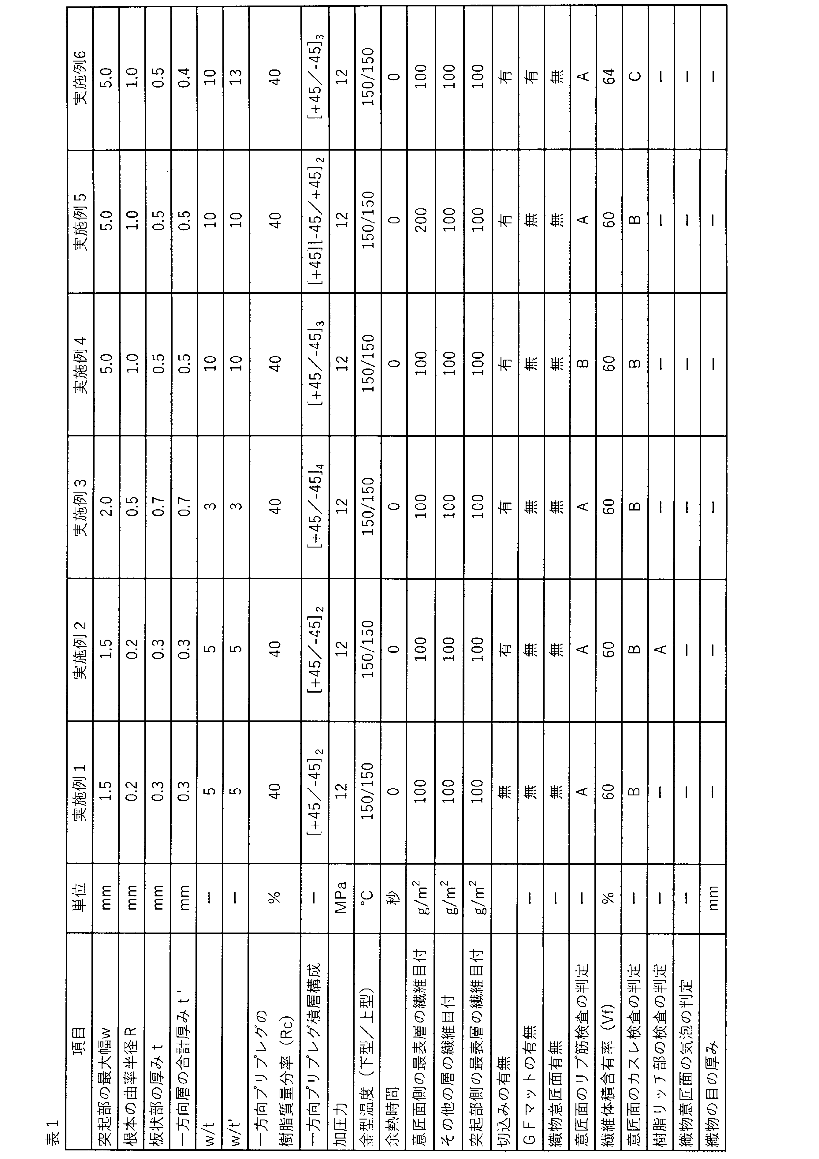
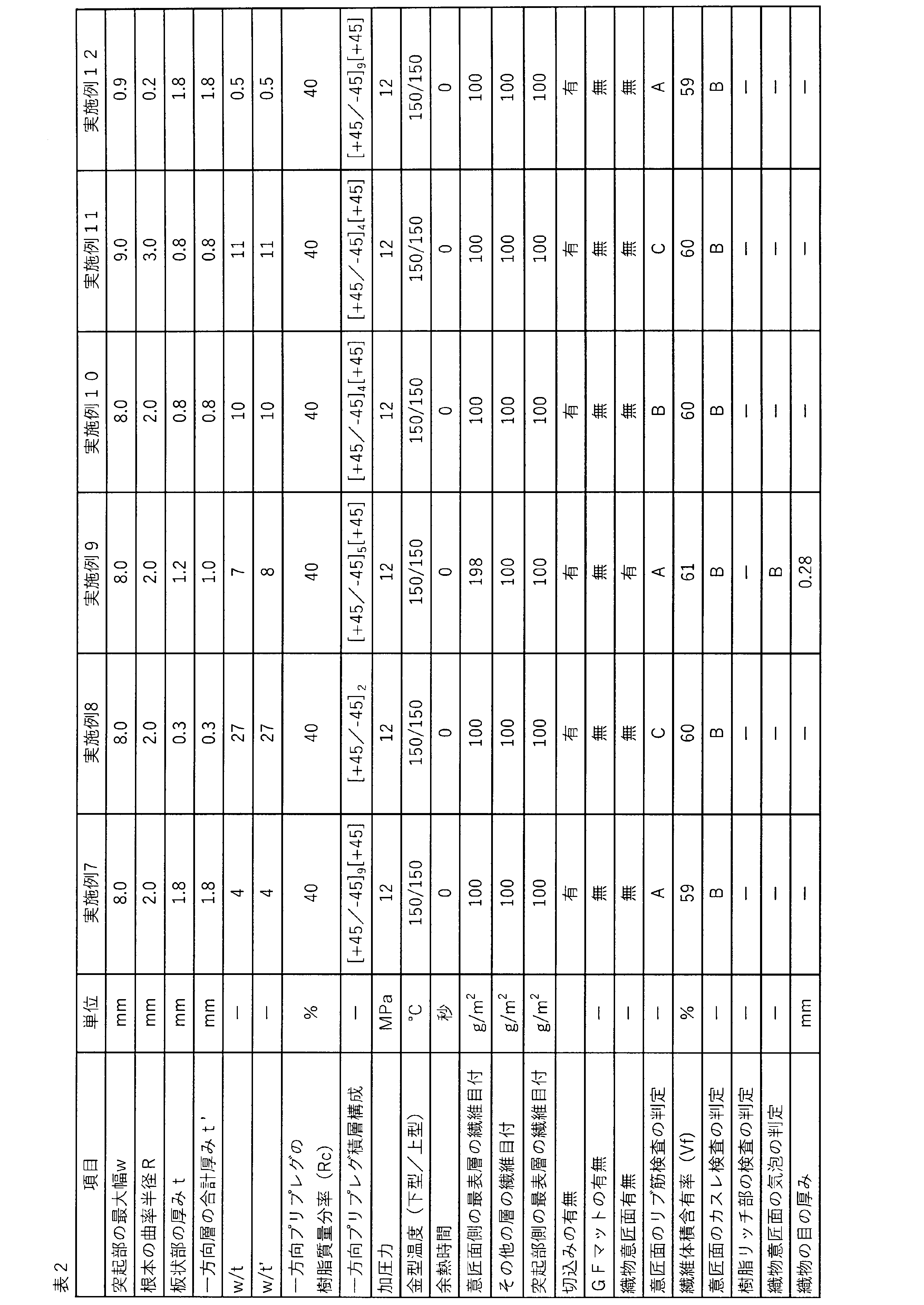
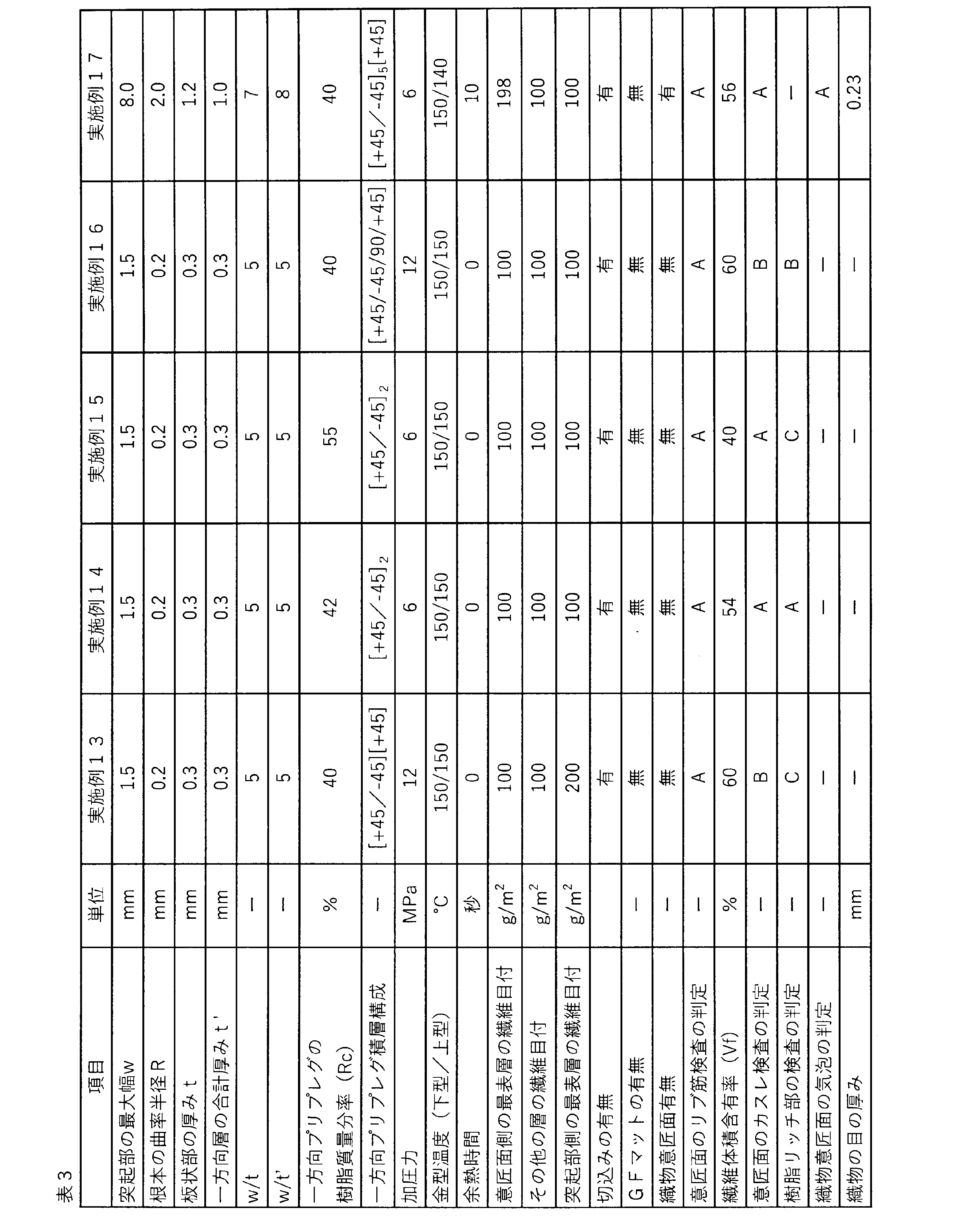
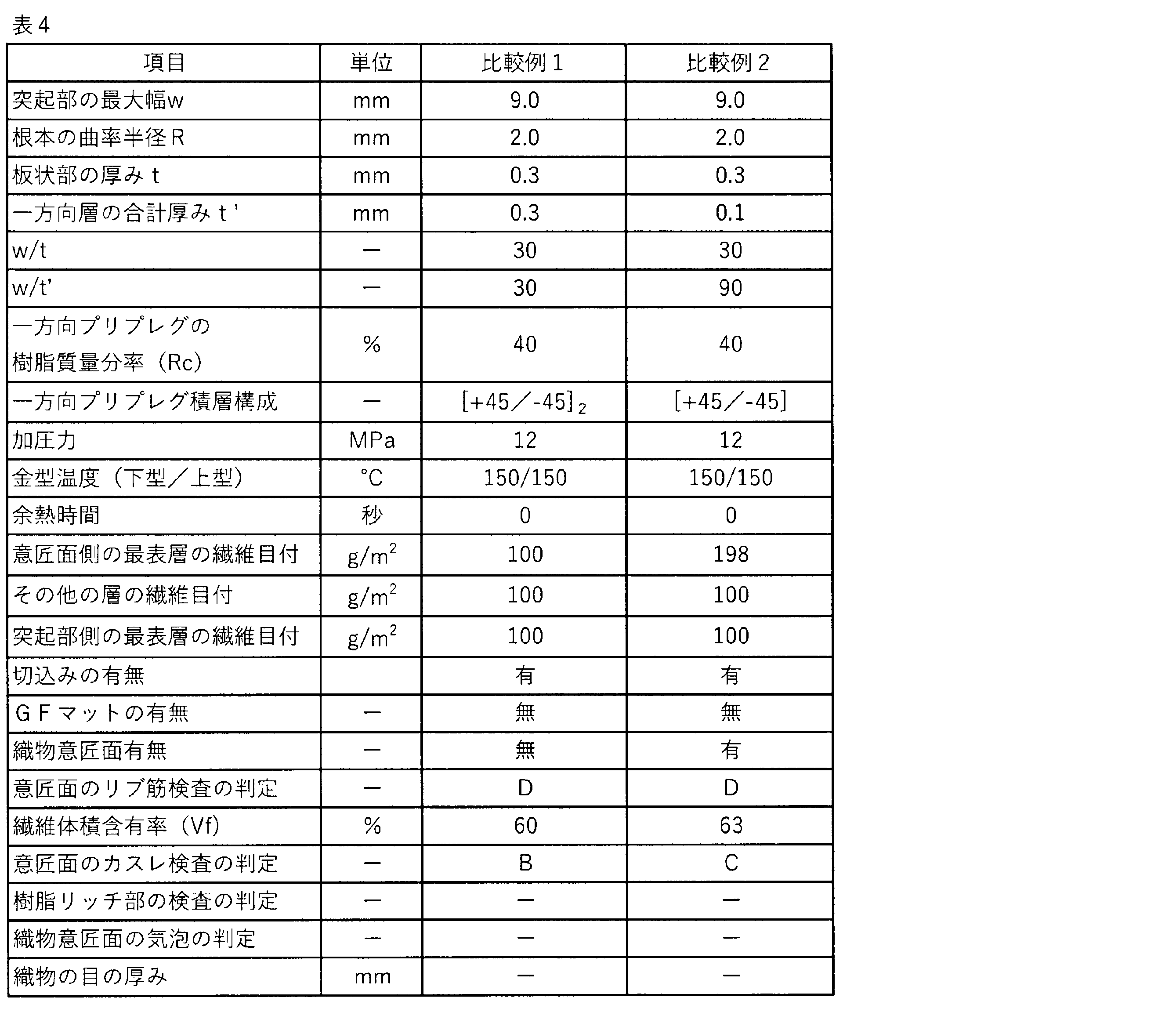
本発明の繊維強化プラスチックは、強度、剛性とともに軽量性が要求される部材や、部材形状が複雑で、他の部材との間で形状追従性が要求される部材に、好ましく利用できる。特に、前述した要求が強い、自転車のクランクやフレームなどの部材、ゴルフクラブのシャフトやヘッドなどのスポーツ部材、自動車の、ドア、シート、メンバー、モジュールあるいはフレームなどの構造部材や外板および内装材、ロボットアームなどの機械部品に用いることができる。その他、医療機器や情報通信機器の構造部材や外板などにも好ましく利用することができる。
1:突起部の最大幅
2:突起部の横断面の幅
3:突起部の高さ
4:切込挿入プリプレグ
5:繊維配向方向
6:繊維垂直方向
7:断続的な切込
8:連続的な切込
9:断続的な斜め切込(繊維方向に対して正の角度)
10:断続的な斜め切込(繊維方向に対して負の角度)
11:断続的な切込の列
20:突起部の長さ方向
21:突起部の幅方向
22:突起部の横断面
23:突起部の縦断面
100:板状部
101:板状部の厚み(t)
102:非一方向層
103:一方向層の合計厚み(t’)
104:織物
105:織物の経糸または緯糸
106:織物の緯糸または経糸
107:織物の目の厚み
108:経糸と緯糸の段差
109:気泡
200:突起部
201:板状部と突起部のなす曲面
202:突起部の最大幅(w)
203:突起部の高さ
300:強化繊維
400:突起部を有する面とは反対側の表層
401:強化繊維
402:目ヨレ
500:凹み
600:“未充填”領域
Claims (16)
- 板状部と該板状部の少なくとも片側の面から隆起した突起部を少なくとも1箇所有する形状からなる繊維強化プラスチックにおいて、前記板状部の内部に、多数本の強化繊維がマトリックス樹脂中で一方向に配列された層(一方向層)を少なくとも1層有し、前記板状部の厚みtが0.3mm以上1.8mm以下であり、前記突起部の最大幅wと前記板状部の厚みtの比w/tが0.1以上27以下である繊維強化プラスチック。
- 前記繊維強化プラスチックの繊維体積含有率(Vf)が43%~58%である、請求項1に記載の繊維強化プラスチック。
- 前記突起部の最大幅wと前記板状部の厚みtの比w/tが2以上27以下である、請求項2に記載の繊維強化プラスチック。
- 前記板状部の内部に前記一方向層を2層以上有し、前記突起部のある側の面から2層の前記一方向層は、繊維配向方向が突起部の長さ方向と非平行および非垂直である、請求項1または2に記載の繊維強化プラスチック。
- 前記板状部の内部にある前記一方向層のうち、少なくとも一層の繊維目付が70g/m2以上100g/m2以下である、請求項1または2に記載の繊維強化プラスチック。
- 前記板状部が強化繊維とマトリックス樹脂からなる層を複数層有し、前記板状部の片側の面のみに前記突起部を有し、その反対側の面の最表層を形成する前記強化繊維が織物である、請求項1または2に記載の繊維強化プラスチック。
- 前記織物の目の厚みが0.25mm以下である請求項6に記載の繊維強化プラスチック。
- 前記突起部と前記板状部とのなす曲面の曲率半径Rが2mm以下である、請求項1または2に記載の繊維強化プラスチック。
- 前記突起部の最大幅wが8mm以下である、請求項1または2に記載の繊維強化プラスチック。
- 前記板状部の内部に繊維目付の異なる2種類以上の前記一方向層を有している、請求項1または2に記載の繊維強化プラスチック。
- 前記板状部における前記突起部のある側の最表層が前記一方向層であり、かつ当該最表層の一方向層の繊維目付が前記板状部中の他の少なくとも1層の一方向層の繊維目付より小さい、請求項10に記載の繊維強化プラスチック。
- 前記板状部が強化繊維とマトリックス樹脂からなる層を複数層有し、前記板状部の片側の面のみに前記突起部を有し、該突起部を有する面の最表層以外の層の少なくとも1層が、多数本の強化繊維がマトリックス樹脂中で少なくとも二方向に配向している層(非一方向層)である、請求項1または2に記載の繊維強化プラスチック。
- 前記板状部が非一方向層を有し、前記突起部の最大幅wと前記非一方向層よりも前記突起部側に位置する一方向層の合計厚みt’の比w/t’が0.1以上27以下である、請求項1または2に記載の繊維強化プラスチック。
- 前記板状部の内部にある前記一方向層のうち、少なくとも1層は、繊維長が10~300mmの強化繊維を含む、請求項1または2に記載の繊維強化プラスチック。
- 一方向に配列した多数本の強化繊維にマトリックス樹脂を含浸させたプリプレグを少なくとも1層金型内に配置し、前記金型を閉じて加熱加圧することにより、請求項1~14のいずれかに記載の繊維強化プラスチックを得る、繊維強化プラスチックの製造方法。
- 請求項1~14のいずれかに記載の繊維強化プラスチックを備えたゴルフクラブ。
Priority Applications (1)
| Application Number | Priority Date | Filing Date | Title |
|---|---|---|---|
| JP2023544630A JPWO2024024563A1 (ja) | 2022-07-26 | 2023-07-18 |
Applications Claiming Priority (2)
| Application Number | Priority Date | Filing Date | Title |
|---|---|---|---|
| JP2022118416 | 2022-07-26 | ||
| JP2022-118416 | 2022-07-26 |
Publications (1)
| Publication Number | Publication Date |
|---|---|
| WO2024024563A1 true WO2024024563A1 (ja) | 2024-02-01 |
Family
ID=89706328
Family Applications (1)
| Application Number | Title | Priority Date | Filing Date |
|---|---|---|---|
| PCT/JP2023/026210 Ceased WO2024024563A1 (ja) | 2022-07-26 | 2023-07-18 | 繊維強化プラスチックおよびその製造方法 |
Country Status (3)
| Country | Link |
|---|---|
| JP (1) | JPWO2024024563A1 (ja) |
| TW (1) | TW202413497A (ja) |
| WO (1) | WO2024024563A1 (ja) |
Citations (1)
| Publication number | Priority date | Publication date | Assignee | Title |
|---|---|---|---|---|
| JP2019167785A (ja) * | 2018-03-26 | 2019-10-03 | 積水化学工業株式会社 | 浸水防止装置、止水板並びに構造体 |
-
2023
- 2023-07-18 JP JP2023544630A patent/JPWO2024024563A1/ja active Pending
- 2023-07-18 WO PCT/JP2023/026210 patent/WO2024024563A1/ja not_active Ceased
- 2023-07-25 TW TW112127711A patent/TW202413497A/zh unknown
Patent Citations (1)
| Publication number | Priority date | Publication date | Assignee | Title |
|---|---|---|---|---|
| JP2019167785A (ja) * | 2018-03-26 | 2019-10-03 | 積水化学工業株式会社 | 浸水防止装置、止水板並びに構造体 |
Also Published As
| Publication number | Publication date |
|---|---|
| TW202413497A (zh) | 2024-04-01 |
| JPWO2024024563A1 (ja) | 2024-02-01 |
Similar Documents
| Publication | Publication Date | Title |
|---|---|---|
| RU2551501C2 (ru) | Формованный продукт, выполненный из композитного материала с армированными волокнами | |
| CN1120775C (zh) | 非织造织物及生产方法 | |
| US8101262B2 (en) | Fiber-reinforced plastic and process for production thereof | |
| US5529826A (en) | Fabric-faced thermoplastic composite panel | |
| JP5320742B2 (ja) | 複合プリプレグ基材の製造方法、積層基材および繊維強化プラスチック | |
| ES2983805T3 (es) | Refuerzo multiaxial cosido y método de producción del mismo | |
| US20140004308A1 (en) | Molded Product Having Thickness Gradient, and Method for Manufacturing the Same | |
| US20100178495A1 (en) | Chopped fiber bundle, molding material, and fiber reinforced plastic, and process for producing them | |
| JP2009114612A (ja) | チョップド繊維束および成形材料の製造方法、成形材料、繊維強化プラスチック | |
| CN101394979A (zh) | 纤维增强树脂的制造方法 | |
| CN109715385B (zh) | 层叠基材及其制造方法 | |
| CN103201087A (zh) | 碳纤维增强塑料成型品 | |
| JP6988812B2 (ja) | プリプレグ積層体及びプリプレグ積層体を用いた繊維強化プラスチックの製造方法 | |
| KR20130121858A (ko) | 강화용 섬유 번들들로부터 제조되고 단일방향 섬유 테이프들을 포함하는 섬유 예비성형체, 및 복합재 부재 | |
| JP2004160927A (ja) | プリフォーム基材、プリフォーム、繊維強化プラスチック成形体およびその成形方法 | |
| TW201726371A (zh) | 構造體 | |
| JP2003136550A (ja) | 炭素繊維基材の製造方法、プリフォームの製造方法および複合材料の製造方法 | |
| US20040226191A1 (en) | Toecap made from woven layers of continuous strands aligned in layer-specific orientation | |
| JP6977709B2 (ja) | 繊維強化プラスチックの製造方法 | |
| JP2001064406A (ja) | 繊維強化複合材用プリフォームおよびこれを用いてなる繊維強化複合材ならびにこれらの製造方法 | |
| CN113573875B (zh) | 缝合的多轴增强件 | |
| US11465372B2 (en) | Dry tape material for fiber placement, method of manufacturing the same, and reinforcing fiber laminate and fiber-reinforced plastic molded body produced with the same | |
| JP4626340B2 (ja) | 強化繊維基材の製造方法および該基材を用いた複合材料の製造方法 | |
| EP3960796A1 (en) | Method for manufacturing molded article of fiber-reinforced composite material, reinforcing fiber substrate and molded article of fiber-reinforced composite material | |
| JP2021518283A (ja) | 三次元コンポジット部品を生産するための、含浸繊維材料のウェブ、その生産方法およびその使用 |
Legal Events
| Date | Code | Title | Description |
|---|---|---|---|
| WWE | Wipo information: entry into national phase |
Ref document number: 2023544630 Country of ref document: JP |
|
| 121 | Ep: the epo has been informed by wipo that ep was designated in this application |
Ref document number: 23846294 Country of ref document: EP Kind code of ref document: A1 |
|
| NENP | Non-entry into the national phase |
Ref country code: DE |
|
| 122 | Ep: pct application non-entry in european phase |
Ref document number: 23846294 Country of ref document: EP Kind code of ref document: A1 |