WO2024024428A1 - 電力変換装置 - Google Patents
電力変換装置 Download PDFInfo
- Publication number
- WO2024024428A1 WO2024024428A1 PCT/JP2023/024915 JP2023024915W WO2024024428A1 WO 2024024428 A1 WO2024024428 A1 WO 2024024428A1 JP 2023024915 W JP2023024915 W JP 2023024915W WO 2024024428 A1 WO2024024428 A1 WO 2024024428A1
- Authority
- WO
- WIPO (PCT)
- Prior art keywords
- connection switch
- storage battery
- switch
- control
- voltage
- Prior art date
- Legal status (The legal status is an assumption and is not a legal conclusion. Google has not performed a legal analysis and makes no representation as to the accuracy of the status listed.)
- Ceased
Links
Images


Classifications
-
- H—ELECTRICITY
- H02—GENERATION; CONVERSION OR DISTRIBUTION OF ELECTRIC POWER
- H02M—APPARATUS FOR CONVERSION BETWEEN AC AND AC, BETWEEN AC AND DC, OR BETWEEN DC AND DC, AND FOR USE WITH MAINS OR SIMILAR POWER SUPPLY SYSTEMS; CONVERSION OF DC OR AC INPUT POWER INTO SURGE OUTPUT POWER; CONTROL OR REGULATION THEREOF
- H02M1/00—Details of apparatus for conversion
- H02M1/08—Circuits specially adapted for the generation of control voltages for semiconductor devices incorporated in static converters
-
- H—ELECTRICITY
- H02—GENERATION; CONVERSION OR DISTRIBUTION OF ELECTRIC POWER
- H02M—APPARATUS FOR CONVERSION BETWEEN AC AND AC, BETWEEN AC AND DC, OR BETWEEN DC AND DC, AND FOR USE WITH MAINS OR SIMILAR POWER SUPPLY SYSTEMS; CONVERSION OF DC OR AC INPUT POWER INTO SURGE OUTPUT POWER; CONTROL OR REGULATION THEREOF
- H02M1/00—Details of apparatus for conversion
- H02M1/0048—Circuits or arrangements for reducing losses
-
- H—ELECTRICITY
- H02—GENERATION; CONVERSION OR DISTRIBUTION OF ELECTRIC POWER
- H02M—APPARATUS FOR CONVERSION BETWEEN AC AND AC, BETWEEN AC AND DC, OR BETWEEN DC AND DC, AND FOR USE WITH MAINS OR SIMILAR POWER SUPPLY SYSTEMS; CONVERSION OF DC OR AC INPUT POWER INTO SURGE OUTPUT POWER; CONTROL OR REGULATION THEREOF
- H02M1/00—Details of apparatus for conversion
- H02M1/32—Means for protecting converters other than automatic disconnection
-
- H—ELECTRICITY
- H02—GENERATION; CONVERSION OR DISTRIBUTION OF ELECTRIC POWER
- H02M—APPARATUS FOR CONVERSION BETWEEN AC AND AC, BETWEEN AC AND DC, OR BETWEEN DC AND DC, AND FOR USE WITH MAINS OR SIMILAR POWER SUPPLY SYSTEMS; CONVERSION OF DC OR AC INPUT POWER INTO SURGE OUTPUT POWER; CONTROL OR REGULATION THEREOF
- H02M7/00—Conversion of AC power input into DC power output; Conversion of DC power input into AC power output
- H02M7/42—Conversion of DC power input into AC power output without possibility of reversal
- H02M7/44—Conversion of DC power input into AC power output without possibility of reversal by static converters
- H02M7/48—Conversion of DC power input into AC power output without possibility of reversal by static converters using discharge tubes with control electrode or semiconductor devices with control electrode
- H02M7/53—Conversion of DC power input into AC power output without possibility of reversal by static converters using discharge tubes with control electrode or semiconductor devices with control electrode using devices of a triode or transistor type requiring continuous application of a control signal
- H02M7/537—Conversion of DC power input into AC power output without possibility of reversal by static converters using discharge tubes with control electrode or semiconductor devices with control electrode using devices of a triode or transistor type requiring continuous application of a control signal using semiconductor devices only, e.g. single switched pulse inverters
- H02M7/5387—Conversion of DC power input into AC power output without possibility of reversal by static converters using discharge tubes with control electrode or semiconductor devices with control electrode using devices of a triode or transistor type requiring continuous application of a control signal using semiconductor devices only, e.g. single switched pulse inverters in a bridge configuration
- H02M7/53871—Conversion of DC power input into AC power output without possibility of reversal by static converters using discharge tubes with control electrode or semiconductor devices with control electrode using devices of a triode or transistor type requiring continuous application of a control signal using semiconductor devices only, e.g. single switched pulse inverters in a bridge configuration with automatic control of output voltage or current
-
- H—ELECTRICITY
- H02—GENERATION; CONVERSION OR DISTRIBUTION OF ELECTRIC POWER
- H02P—CONTROL OR REGULATION OF ELECTRIC MOTORS, ELECTRIC GENERATORS OR DYNAMO-ELECTRIC CONVERTERS; CONTROLLING TRANSFORMERS, REACTORS OR CHOKE COILS
- H02P29/00—Arrangements for regulating or controlling electric motors, appropriate for both AC and DC motors
- H02P29/02—Providing protection against overload without automatic interruption of supply
- H02P29/024—Detecting a fault condition, e.g. short circuit, locked rotor, open circuit or loss of load
- H02P29/0241—Detecting a fault condition, e.g. short circuit, locked rotor, open circuit or loss of load the fault being an overvoltage
-
- H—ELECTRICITY
- H02—GENERATION; CONVERSION OR DISTRIBUTION OF ELECTRIC POWER
- H02P—CONTROL OR REGULATION OF ELECTRIC MOTORS, ELECTRIC GENERATORS OR DYNAMO-ELECTRIC CONVERTERS; CONTROLLING TRANSFORMERS, REACTORS OR CHOKE COILS
- H02P29/00—Arrangements for regulating or controlling electric motors, appropriate for both AC and DC motors
- H02P29/60—Controlling or determining the temperature of the motor or of the drive
- H02P29/62—Controlling or determining the temperature of the motor or of the drive for raising the temperature of the motor
-
- H—ELECTRICITY
- H02—GENERATION; CONVERSION OR DISTRIBUTION OF ELECTRIC POWER
- H02P—CONTROL OR REGULATION OF ELECTRIC MOTORS, ELECTRIC GENERATORS OR DYNAMO-ELECTRIC CONVERTERS; CONTROLLING TRANSFORMERS, REACTORS OR CHOKE COILS
- H02P3/00—Arrangements for stopping or slowing electric motors, generators, or dynamo-electric converters
- H02P3/06—Arrangements for stopping or slowing electric motors, generators, or dynamo-electric converters for stopping or slowing an individual dynamo-electric motor or dynamo-electric converter
- H02P3/18—Arrangements for stopping or slowing electric motors, generators, or dynamo-electric converters for stopping or slowing an individual dynamo-electric motor or dynamo-electric converter for stopping or slowing an AC motor
- H02P3/22—Arrangements for stopping or slowing electric motors, generators, or dynamo-electric converters for stopping or slowing an individual dynamo-electric motor or dynamo-electric converter for stopping or slowing an AC motor by short-circuit or resistive braking
-
- H—ELECTRICITY
- H02—GENERATION; CONVERSION OR DISTRIBUTION OF ELECTRIC POWER
- H02M—APPARATUS FOR CONVERSION BETWEEN AC AND AC, BETWEEN AC AND DC, OR BETWEEN DC AND DC, AND FOR USE WITH MAINS OR SIMILAR POWER SUPPLY SYSTEMS; CONVERSION OF DC OR AC INPUT POWER INTO SURGE OUTPUT POWER; CONTROL OR REGULATION THEREOF
- H02M1/00—Details of apparatus for conversion
- H02M1/0003—Details of control, feedback or regulation circuits
- H02M1/0009—Devices or circuits for detecting current in a converter
-
- H—ELECTRICITY
- H02—GENERATION; CONVERSION OR DISTRIBUTION OF ELECTRIC POWER
- H02P—CONTROL OR REGULATION OF ELECTRIC MOTORS, ELECTRIC GENERATORS OR DYNAMO-ELECTRIC CONVERTERS; CONTROLLING TRANSFORMERS, REACTORS OR CHOKE COILS
- H02P2209/00—Indexing scheme relating to controlling arrangements characterised by the waveform of the supplied voltage or current
- H02P2209/01—Motors with neutral point connected to the power supply
-
- H—ELECTRICITY
- H02—GENERATION; CONVERSION OR DISTRIBUTION OF ELECTRIC POWER
- H02P—CONTROL OR REGULATION OF ELECTRIC MOTORS, ELECTRIC GENERATORS OR DYNAMO-ELECTRIC CONVERTERS; CONTROLLING TRANSFORMERS, REACTORS OR CHOKE COILS
- H02P27/00—Arrangements or methods for the control of AC motors characterised by the kind of supply voltage
- H02P27/04—Arrangements or methods for the control of AC motors characterised by the kind of supply voltage using variable-frequency supply voltage, e.g. inverter or converter supply voltage
- H02P27/06—Arrangements or methods for the control of AC motors characterised by the kind of supply voltage using variable-frequency supply voltage, e.g. inverter or converter supply voltage using DC to AC converters or inverters
- H02P27/08—Arrangements or methods for the control of AC motors characterised by the kind of supply voltage using variable-frequency supply voltage, e.g. inverter or converter supply voltage using DC to AC converters or inverters with pulse width modulation
Definitions
- the present disclosure relates to a power conversion device.
- a known power conversion device includes a rotating electric machine having windings and an inverter having a series connection of an upper arm switch and a lower arm switch.
- a connection path that electrically connects the negative electrode side of the first storage battery, the positive electrode side of the second storage battery, and the neutral point of the winding, and a connection path that is provided in the connection path.
- a power converter device is described that includes a connection switch. This power conversion device performs temperature increase control to increase the temperatures of the first storage battery and the second storage battery while the connection switch is turned on.
- short-circuit control may be performed in which either the upper arm switch or the lower arm switch is turned on and the other is turned off.
- the short-circuit control is a control performed to suppress the occurrence of an overvoltage abnormality due to the application of back electromotive voltage generated in the windings to the first storage battery and the second storage battery due to the rotation of the rotor in the rotating electric machine.
- short-circuit control is performed with the connection switch turned on, there is a possibility that the back electromotive force generated in the winding will be applied to the first storage battery or the second storage battery via the connection path. Therefore, there is a concern that the reliability of the first storage battery and the second storage battery may decrease.
- the present disclosure has been made in view of the above problems, and its main purpose is to provide a power conversion device that can suppress a decrease in reliability of a first storage battery and a second storage battery connected in series. That's true.
- the present disclosure provides a power conversion device including a rotating electric machine having windings connected in a star shape, and an inverter having a series connection body of an upper arm switch and a lower arm switch.
- a connection path that electrically connects the negative electrode side of the first storage battery, the positive electrode side of the second storage battery, and the neutral point of the winding in the storage battery;
- the negative electrode side of the first storage battery and the positive electrode side of the second storage battery are electrically connected to the neutral point, and when the neutral point is turned off, the negative electrode side of the first storage battery and the positive electrode side of the second storage battery are connected to the neutral point.
- connection switch that electrically isolates the connection switch from the sex point; a control unit that controls switching of the upper arm switch and the lower arm switch while turning on the connection switch;
- the device includes a determination unit that determines whether or not to perform short-circuit control in which one of the switches is turned on and the other is turned off, and a cut-off unit that turns off the connection switch when it is determined that the short-circuit control is performed.
- connection switch With the connection switch turned on, switching control of the upper arm switch and lower arm switch may be performed. In this case, for example, if it is determined that short-circuit control is to be performed due to an abnormality in the power conversion device during switching control, short-circuit control may be performed while the connection switch is turned on.
- the connection switch is turned off. This suppresses the occurrence of a period in which short-circuit control is performed while the connection switch is turned on. Therefore, it is possible to suppress the back electromotive voltage generated in the winding from being applied to at least one of the first storage battery and the second storage battery. As a result, it is possible to suppress the first storage battery and the second storage battery from being in an overvoltage state, and it is possible to suppress the reliability of the first storage battery and the second storage battery from decreasing.
- FIG. 1 is a configuration diagram of a power conversion system according to a first embodiment
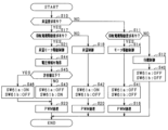
- FIG. 2 is a flowchart showing the processing procedure of switching control
- FIG. 3 is a diagram showing a control circuit and its peripheral configuration
- FIG. 4 is a time chart showing the transition of phase current in a comparative example
- FIG. 5 is a diagram showing an example of a current path in a comparative example
- FIG. 6 is a time chart showing the procedure of shutoff control
- FIG. 7 is a time chart showing the transition of phase current
- FIG. 8 is a time chart showing an example of a current path
- FIG. 1 is a configuration diagram of a power conversion system according to a first embodiment
- FIG. 2 is a flowchart showing the processing procedure of switching control
- FIG. 3 is a diagram showing a control circuit and its peripheral configuration
- FIG. 4 is a time chart showing the transition of phase current in a comparative example
- FIG. 5 is a diagram showing an example of a current path in a comparative
- FIG. 9 is a configuration diagram of a power conversion system according to a second embodiment
- FIG. 10 is a time chart showing an example of control before and after three-phase short circuit control is performed
- FIG. 11 is a configuration diagram of a power conversion system according to a third embodiment
- FIG. 12 is a flowchart showing the processing procedure of switching control
- FIG. 13 is a flowchart showing a switching control processing procedure according to a modification of the third embodiment
- FIG. 14 is a diagram showing a control circuit and its peripheral configuration according to the fourth embodiment
- FIG. 15 is a flowchart of processing performed by the determination unit
- FIG. 16 is a diagram showing a connection path and its peripheral configuration according to another embodiment
- FIG. 17 is a diagram showing a connection path and its peripheral configuration according to another embodiment
- FIG. 16 is a diagram showing a connection path and its peripheral configuration according to another embodiment
- FIG. 17 is a diagram showing a connection path and its peripheral configuration according to another embodiment
- FIG. 16 is a diagram showing a
- FIG. 18 is a diagram showing a connection path and its peripheral configuration according to another embodiment
- FIG. 19 is a diagram showing a connection path and its peripheral configuration according to another embodiment
- FIG. 20 is a diagram showing a connection path and its peripheral configuration according to another embodiment
- FIG. 21 is a diagram showing a connection path and its peripheral configuration according to another embodiment
- FIG. 22 is a diagram showing a connection path and its peripheral configuration according to another embodiment
- FIG. 23 is a diagram showing a connection path and its peripheral configuration according to another embodiment
- FIG. 24 is a diagram showing a connection path and its peripheral configuration according to another embodiment
- FIG. 25 is a diagram showing a connection path and its peripheral configuration according to another embodiment
- FIG. 26 is a diagram showing a connection path and its peripheral configuration according to another embodiment
- FIG. 27 is a diagram showing a connection path and its peripheral configuration according to another embodiment.
- the power conversion system 10 includes a power conversion device 11 and a battery pack 20.
- the assembled battery 20 is configured as a series connection of battery cells as single cells, and has a terminal voltage of, for example, several hundred volts.
- the terminal voltages (for example, rated voltages) of each battery cell constituting the assembled battery 20 are set to be the same.
- a secondary battery such as a lithium ion battery can be used.
- the assembled battery 20 is provided outside the power conversion device 11, for example.
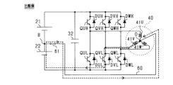
- the power conversion device 11 includes an inverter 30 and a rotating electric machine 40.
- the rotating electric machine 40 is a three-phase synchronous machine, and includes U, V, and W phase windings 41U, 41V, and 41W connected in a star shape as stator windings.
- the phase windings 41U, 41V, and 41W are arranged to be shifted by 120 degrees in electrical angle.
- the rotating electric machine 40 is, for example, a permanent magnet synchronous machine.
- the rotating electric machine 40 is a vehicle-mounted main engine and serves as a driving power source for the vehicle.
- the inverter 30 includes a switching device section 31.
- the switching device section 31 includes three phases of U, V, W phase upper arm switches QUH, QVH, QWH and U, V, W phase lower arm switches QUL, QVL, QWL connected in series.
- voltage-controlled semiconductor switching elements are used as the switches QUH, QVH, QWH, QUL, QVL, and QWL, and specifically, IGBTs are used. Therefore, the high potential side terminal of each switch QUH, QVH, QWH, QUL, QVL, QWL is a collector, and the low potential side terminal is an emitter.
- Diodes DUH, DVH, DWH, DUL, DVL, and DWL as freewheel diodes are connected in antiparallel to each switch QUH, QVH, QWH, QUL, QVL, and QWL.
- a first end of a U-phase winding 41U is connected to the emitter of the U-phase upper arm switch QUH and the collector of the U-phase lower arm switch QUL via a U-phase conductive member 33U such as a bus bar.
- a first end of a V-phase winding 41V is connected to the emitter of the V-phase upper arm switch QVH and the collector of the V-phase lower arm switch QVL via a V-phase conductive member 33V such as a bus bar.
- a first end of a W-phase winding 41W is connected to the emitter of the W-phase upper arm switch QWH and the collector of the W-phase lower arm switch QWL via a W-phase conductive member 33W such as a bus bar.
- phase windings 41U, 41V, and 41W are connected at a neutral point O.
- the number of turns of each phase winding 41U, 41V, and 41W is set to be the same.
- the phase windings 41U, 41V, and 41W are set to have the same inductance, for example.
- the collectors of the upper arm switches QUH, QVH, and QWH and the positive terminal of the battery pack 20 are connected by a positive bus Lp such as a bus bar.
- the emitters of the lower arm switches QUL, QVL, QWL and the negative terminal of the assembled battery 20 are connected by a negative bus line Ln such as a bus bar.
- a positive-side cutoff switch 23 is provided on the positive-side bus Lp, and a negative-side cutoff switch 24 is provided on the negative-side bus Ln.
- Each cutoff switch 23, 24 is, for example, a mechanical relay or a semiconductor switching element.
- the control device 70 turns on and off each cutoff switch 23, 24 depending on whether the power conversion system 10 is activated.
- the control device 70 is configured to be able to input a signal notifying that the starting switch 51 has been turned on or off.
- the start switch 51 is, for example, an ignition switch or a push-type start switch, and is operated by a user of the vehicle.
- the control device 70 starts the power conversion system 10.
- each cutoff switch 23, 24 is turned on.
- the control device 70 stops the power conversion system 10. In this case, each cutoff switch 23, 24 is turned off.
- each cutoff switch 23 may be turned on and off by a control device higher than the control device 70.
- the power converter 11 includes a smoothing capacitor 32 that connects the positive bus Lp and the negative bus Ln. Note that the smoothing capacitor 32 may be built into the inverter 30 or may be provided outside the inverter 30.
- a series connection of a plurality of battery cells on the high potential side constitutes the first storage battery 21
- a series connection of a plurality of battery cells on the low potential side constitutes the second storage battery 22. It consists of That is, the assembled battery 20 is divided into two blocks. In the assembled battery 20, the negative terminal of the first storage battery 21 and the positive terminal of the second storage battery 22 are connected via an intermediate terminal B. In this embodiment, the number of battery cells that make up the first storage battery 21 and the number of battery cells that make up the second storage battery 22 are the same. Therefore, the terminal voltage (for example, rated voltage) of the first storage battery 21 and the terminal voltage (for example, rated voltage) of the second storage battery 22 are the same.
- the power conversion device 11 includes a monitoring unit 50.
- the monitoring unit 50 detects the terminal voltage, temperature, etc. of each battery cell that constitutes the assembled battery 20, and monitors the state of the assembled battery 20.
- the monitoring unit 50 is capable of communicating with a control device 70 included in the power conversion device 11.
- the monitoring unit 50 detects the terminal voltage VB of the assembled battery 20, the terminal voltage VH of the first storage battery 21, and the terminal voltage VL of the second storage battery 22, and these detected values are input to the control device 70.
- the power conversion device 11 includes a connection path 60 and a connection switch 61a.
- the connection path 60 electrically connects the intermediate terminal B and the neutral point O of the assembled battery 20.
- the connection switch 61a is a switch that is provided on the connection path 60 and switches between conduction and interruption of the current flowing through the connection path 60.
- a mechanical relay is used as the connection switch 61a.
- the power conversion device 11 includes a phase current sensor 62, a neutral point current sensor 63, and an angle sensor 64.
- the phase current sensor 62 detects each phase current Iu, Iv, and Iw flowing through each conductive member 33U to 33W.
- Neutral point current sensor 63 detects neutral point current IMr flowing to neutral point O.
- the angle sensor 64 is, for example, a resolver, and detects the rotation angle ⁇ (eg, electrical angle) of the rotor of the rotating electric machine 40.
- the detected values of the phase current sensor 62, neutral point current sensor 63, and angle sensor 64 are input to the control device 70.
- the power conversion system 10 includes an acceleration sensor 52 and a leakage detection device 53.
- the acceleration sensor 52 detects the acceleration ar of the vehicle.
- the detected value of the acceleration sensor 52 is input to the control device 70.
- the earth leakage detection device 53 includes a coupling capacitor 53a, a resistor 53b, an oscillating part 53c, and a detection part 53d, and detects earth leakage in a high voltage circuit including the assembled battery 20, the inverter 30, and the rotating electric machine 40.
- High voltage circuits are electrically isolated from ground.
- the insulation state between the negative bus Ln of the inverter 30 and the ground and between the W-phase conductive member 33W and the ground is represented as the insulation resistance RL.
- Earth leakage in a high voltage circuit occurs due to current flowing through an insulation resistance RL between the high voltage circuit and ground.
- the ground is, for example, a body ground constituted by a metal body frame of a vehicle.
- the coupling capacitor 53a is connected to the negative terminal of the second storage battery 22 and insulates the DC component.
- the resistor 53b is connected in series to the coupling capacitor 53a on the side opposite to the second storage battery 22, and is also connected in series to the oscillation section 53c.
- the detection section 53d is connected to a connection point between the coupling capacitor 53a and the resistor 53b.
- the earth leakage detection device 53 performs earth leakage detection operation of the high voltage circuit while the vehicle is stopped.
- the oscillator 53c generates a pulse voltage (ie, AC voltage) at a predetermined frequency, and applies the pulse voltage at the predetermined frequency to the resistor 53b.
- the detection unit 53d detects the ground voltage at the connection point between the coupling capacitor 53a and the resistor 53b. This ground voltage is a voltage obtained by dividing the AC voltage applied to the resistor 53b by the resistance value of the resistor 53b and the insulation resistance RL of the high voltage circuit. Furthermore, the detection unit 53d determines whether there is a current leakage in the high voltage circuit based on the detected ground voltage. Note that the earth leakage detection device 53 is not limited to performing the earth leakage detection operation while the vehicle is stopped, but may perform the earth leakage detection operation while the vehicle is running.
- the detection unit 53d When the leakage detection operation of the high voltage circuit is performed, the detection unit 53d outputs a signal Sge indicating that the leakage detection operation is to be performed. A signal Sge indicating that an earth leakage detection operation is to be performed is input to the control device 70.
- the control device 70 realizes various control functions by executing programs stored in its own storage device.
- Various control functions may be realized by electronic circuits that are hardware, or may be realized by both hardware and software.
- the switching control includes motor drive control, temperature increase control, and temperature increase motor drive control.
- control device 70 performs motor drive control to perform feedback control of the control amount of the rotating electrical machine 40 to its command value.
- the control amount for motor drive control is, for example, torque.
- the upper and lower arm switches are turned on alternately in each phase.
- the control device 70 performs temperature increase control to increase the temperature of the assembled battery 20 as switching control.
- the temperature increase control when the connection switch 61a is turned on, an alternating current is generated between the first storage battery 21 and the second storage battery 22 via the switching device section 31, each phase winding 41U, 41V, 41W, and the connection path 60.
- Each of the switches QUH to QWL is turned on and off so that current flows. Thereby, power is transferred between the first storage battery 21 and the second storage battery 22, and the transferred power is converted into thermal energy in each storage battery 21, 22. The converted thermal energy is used to raise the temperature of the assembled battery 20.
- the control device 70 performs heating motor drive control as switching control.
- the temperature increasing motor drive control is a control that increases the temperature of the assembled battery 20 while feedback controlling the control amount of the rotating electrical machine 40 to its command value. That is, in the temperature increase motor drive control, temperature increase control is performed while motor drive control is performed.
- This control is repeatedly executed by the control device 70, for example, at a predetermined control cycle.
- step S10 it is determined whether there is a request to raise the temperature of the first storage battery 21 and the second storage battery 22.
- the temperature of the assembled battery 20 may be acquired from the monitoring unit 50. Note that as the temperature of the assembled battery 20, the temperature of the first storage battery 21, the temperature of the second storage battery 22, or the average temperature of the first storage battery 21 and the second storage battery 22 may be used.
- step S10 If it is determined in step S10 that there is no request to raise the temperature, the process proceeds to step S11, and it is determined whether or not there is a request to drive the rotating electric machine 40.
- the drive request for the rotating electric machine 40 is a drive request to rotationally drive the rotor of the rotating electric machine 40. Whether or not there is a request to drive the rotating electric machine 40 may be determined based on, for example, a torque command value transmitted to the control device 70 from a higher-level control device.
- step S11 If it is determined in step S11 that there is no request to drive the rotating electrical machine 40, the process advances to step S12 and standby control is performed. In standby control, each switch QUH to QWL of the inverter 30 is turned off. Then, in step S13, the connection switch 61a is turned off. Thereby, intermediate terminal B and neutral point O are electrically disconnected.
- step S11 If it is determined in step S11 that there is a request to drive the rotating electric machine 40, the process proceeds to step S14, where motor drive control is performed. Then, in step S15, the connection switch 61a is turned off. Thereby, intermediate terminal B and neutral point O are electrically disconnected.
- step S16 PWM processing is performed.
- PWM processing is processing that generates switching commands for each of the switches QUH to QWL based on a magnitude comparison between the U, V, and W phase modulation rates and a carrier signal (for example, a triangular wave signal).
- U, V, and W phase modulation rates are calculated based on the torque command value of the rotating electrical machine 40.
- the torque command value of the rotating electric machine 40 output from the higher-level control device to the control device 70 is acquired. Based on the torque command value of the rotating electric machine 40, d and q axis command currents are set. Further, the detection value of the phase current sensor 62 and the detection value of the angle sensor 64 are acquired. Based on the detected value of the phase current sensor 62 and the detected value of the angle sensor 64, d and q-axis currents are calculated.
- a d-axis command voltage is calculated as a manipulated variable for feedback controlling the d-axis current to the d-axis command current.
- a q-axis command voltage is calculated as a manipulated variable for feedback controlling the q-axis current to the q-axis command current. Note that the feedback control is, for example, proportional-integral control.
- the d- and q-axis command voltages are converted into U-, V-, and W-phase command voltages in a three-phase fixed coordinate system.
- the U, V, and W phase command voltages have waveforms whose phases are shifted by 120 degrees in electrical angle.
- the U-phase final command voltage is calculated by adding the offset correction amount to the U-phase command voltage.
- the offset correction amount is a command voltage that is added to the U, V, and W phase command voltages when temperature increase control is performed. In motor drive control, the offset correction amount is zero. That is, in motor drive control, the U, V, and W phase final command voltages are the U, V, and W phase command voltages.
- the V-phase final command voltage is calculated by adding the offset correction amount to the V-phase command voltage.
- the W-phase final command voltage is calculated by adding the offset correction amount to the W-phase command voltage. Note that a method for calculating the offset correction amount will be described later.
- the U, V, and W phase modulation factors are calculated by dividing the U, V, and W phase final command voltages by the power supply voltage.
- the power supply voltage is, for example, 1/2 of the total value of the terminal voltages VB of the assembled battery 20 acquired from the monitoring unit 50.
- step S10 If it is determined in step S10 that there is a temperature increase request, the process proceeds to step S17.
- step S17 similarly to the process in step S11, it is determined whether there is a request to drive the rotating electrical machine 40.
- step S17 If it is determined in step S17 that there is no request to drive the rotating electrical machine 40, the process proceeds to step S18 and temperature increase control is performed. Then, in step S19, the connection switch 61a is turned on. Thereby, the intermediate terminal B and the neutral point O are electrically connected via the connection path 60.
- step S20 PWM processing is performed.
- U, V, and W phase modulation rates are calculated based on the target temperature of the assembled battery 20.
- the target temperature of the battery pack 20 outputted from a higher-level control device to the control device 70 is acquired. Based on the target temperature of the assembled battery 20, a neutral point command current is set.
- the waveform of the neutral point command current is set as, for example, a sine wave.
- An offset correction amount is calculated as a manipulated variable for feedback controlling the detected value of the neutral point current sensor 63 to the neutral point command current.
- the feedback control is, for example, proportional-integral control.
- the process of calculating the U, V, and W phase modulation factors is the same as in the case of motor drive control. However, in temperature increase control, since the U, V, and W phase command voltages are 0, the U, V, and W phase final command voltages are offset correction amounts. The U, V, and W phase modulation factors are calculated by dividing the offset correction amount by the power supply voltage.
- step S17 If it is determined in step S17 that there is a request to drive the rotating electric machine 40, the process proceeds to step S21, where temperature raising motor drive control is performed. Then, in step S22, the connection switch 61a is turned on.
- step S23 PWM processing is performed.
- U, V, and W phase modulation rates are calculated based on the torque command value of the rotating electric machine 40 and the target temperature of the assembled battery 20.
- the U-phase final command voltage is calculated by adding the offset correction amount to the U-phase command voltage.
- the V-phase final command voltage is calculated by adding the offset correction amount to the V-phase command voltage.
- the W-phase final command voltage is calculated by adding the offset correction amount to the W-phase command voltage.
- the U, V, and W phase modulation factors are calculated by dividing the U, V, and W phase final command voltages by the power supply voltage. Note that the method for calculating the U, V, and W phase command voltages is the same as in the case of motor drive control. Further, the method for calculating the offset correction amount is the same as in the case of temperature increase control.
- the three-phase short circuit control is a control in which one of the upper arm switches QUH to QWH and each of the lower arm switches QUL to QWL is turned on and the other is turned off.
- the three-phase short circuit control is intended to suppress the back electromotive voltage generated in each phase winding 41U, 41V, and 41W from being applied to the assembled battery 20 and the smoothing capacitor 32 as the rotor of the rotating electric machine 40 rotates. It will be done.
- the control device 70 performs three-phase short circuit control by turning off each of the upper arm switches QUH to QWH and turning on each of the lower arm switches QUL to QWL.
- the control device 70 includes an input circuit 71 and a power supply circuit 72.
- the input circuit 71 and the power supply circuit 72 are provided in a low voltage region.
- a positive terminal of a low voltage power supply 26 is connected to the input circuit 71 via a fuse 25 .
- the negative terminal of the low voltage power supply 26 is connected to a ground serving as a grounding site.
- the low-voltage power supply 26 is a secondary battery whose output voltage (rated voltage) is lower than the output voltage (rated voltage) of the assembled battery 20 (for example, 12 V), and is, for example, a lead-acid battery.
- the power supply circuit 72 is supplied with power from the input circuit 71 and generates the second voltage V2. In this embodiment, the power supply circuit 72 generates the second voltage V2 (eg, 5V) by stepping down the first voltage V1 output by the input circuit 71.
- the control device 70 includes a microcomputer 73.
- the microcomputer 73 includes a CPU and other peripheral circuits.
- the peripheral circuit includes an input/output section for exchanging signals with the outside.
- the microcomputer 73 includes the detection values of the monitoring unit 50, the acceleration sensor 52, the phase current sensor 62, the neutral point current sensor 63, and the angle sensor 64, a signal that notifies the on/off status of the starting switch 51, and the leakage detection operation of the detection unit 53d. A signal Sge to the effect that this is to be performed is input.
- the microcomputer 73 performs the above-mentioned PWM processing to generate a switching command that turns on the upper arm switches QUH to QWH of each phase and the lower arm switches QUL to QWL of each phase alternately.
- the input circuit 71, power supply circuit 72, and microcomputer 73 are provided in a low voltage region of the control device 70.
- the control device 70 includes an insulated power supply 74, an upper arm driver 75, and a lower arm driver 76.
- the insulated power supply 74 and the respective drivers 75 and 76 are provided in the low voltage area and the high voltage area in the control device 70, straddling the boundary between the low voltage area and the high voltage area from which the low voltage area is electrically insulated.
- the isolated power supply 74 includes an upper arm isolated power supply provided individually for each of the three-phase upper arm drivers 75, and a lower arm isolated power supply common to the three-phase lower arm drivers 76.
- the lower arm insulated power supply may be provided individually for each of the three-phase lower arm drivers 76.
- the isolated power supply 74 generates an upper arm drive voltage VdH to be supplied to the upper arm driver 75 and a lower arm drive voltage VdL to be supplied to the lower arm driver 76 based on the first voltage V1 supplied from the input circuit 71. output to the high pressure area.
- the insulated power supply 74 is, for example, a flyback type insulated power supply.
- the upper arm driver 75 is provided individually corresponding to each phase upper arm switch QUH to QWH.
- the upper arm driver 75 has an upper arm drive section and an upper arm insulated transmission section.
- the upper arm drive section is provided in a high pressure region.
- the upper arm insulation transmission section is provided in the low voltage region and the high voltage region, straddling the boundary between the low voltage region and the high voltage region.
- the upper arm insulation transmission section transmits the switching command output from the microcomputer 73 to the upper arm drive section while electrically insulating the low voltage region and the high voltage region.
- the upper arm insulation transmission section is, for example, a photocoupler or a magnetic coupler.
- the configuration of the upper arm driving section and the upper arm insulated transmission section on the high voltage region side of the upper arm driver 75 is configured to be operable by being supplied with the upper arm drive voltage VdH of the insulated power supply 74.
- the configuration on the low voltage region side of the upper arm insulated transmission section is configured to be operable by being supplied with the second voltage V2 of the power supply circuit 72.
- the upper arm drive unit supplies charging current to the gates of each of the upper arm switches QUH to QWH when the switching command for each of the upper arm switches QUH to QWH input via the upper arm insulation transmission unit is an ON command.
- the gate voltage of each of the upper arm switches QUH to QWH becomes equal to or higher than the threshold voltage Vth, and each of the upper arm switches QUH to QWH is turned on.
- the upper arm driving section causes a discharge current to flow from the gate of each of the upper arm switches QUH to QWH to the emitter side.
- the gate voltage of each of the upper arm switches QUH to QWH becomes less than the threshold voltage Vth, and each of the upper arm switches QUH to QWH is turned off.
- Each upper arm switch QUH to QWH is provided with each upper arm sense terminal SUH to SWH.
- a minute current having a correlation with the collector current of the corresponding upper arm switch QUH to QWH flows through each upper arm sense terminal SUH to SWH.
- the current flowing through each of the upper arm sense terminals SUH to SWH is detected as a potential difference (hereinafter referred to as upper arm sense voltage) between the upper arm sense resistors RUH to RWH connected to the sense terminals SUH to SWH, and is applied to the upper arm driver 75. is input.
- the detected value of the upper arm sense voltage is input to the microcomputer 73 via the upper arm driver 75.
- the lower arm driver 76 is individually provided corresponding to each phase lower arm switch QUL to QWL.
- the lower arm driver 76 has a lower arm drive section and a lower arm insulation transmission section.
- the lower arm drive section is provided in a high pressure area.
- the lower arm insulation transmission section is provided in the low voltage region and the high voltage region, straddling the boundary between the low voltage region and the high voltage region.
- the lower arm insulation transmission section transmits the switching command output from the microcomputer 73 to the lower arm drive section while electrically insulating the low voltage region and the high voltage region.
- the lower arm insulation transmission section is, for example, a photocoupler or a magnetic coupler.
- the configuration of the lower arm drive section and the lower arm insulated transmission section on the high voltage region side of the lower arm driver 76 is configured to be operable by being supplied with the lower arm drive voltage VdL of the insulated power supply 74.
- the configuration of the lower arm insulation transmission section on the low voltage region side is configured to be operable by being supplied with the second voltage V2 of the power supply circuit 72.
- the lower arm drive section supplies a charging current to the gate of each of the lower arm switches QUL to QWL when the switching command for each of the lower arm switches QUL to QWL input via the lower arm insulation transmission section is an ON command.
- the gate voltage of each of the lower arm switches QUL to QWL becomes equal to or higher than the threshold voltage Vth, and each of the lower arm switches QUL to QWL is turned on.
- the lower arm driving section causes a discharge current to flow from the gate of each of the lower arm switches QUL to QWL to the emitter side.
- the gate voltage of each of the lower arm switches QUL to QWL becomes less than the threshold voltage Vth, and each of the lower arm switches QUL to QWL is turned off.
- Each lower arm switch QUL to QWL is provided with a lower arm sense terminal SUL to SWL.
- a minute current having a correlation with the collector current of the corresponding lower arm switch QUL to QWL flows through each of the lower arm sense terminals SUL to SWL.
- the current flowing through each of the lower arm sense terminals SUL to SWL is detected as a potential difference (hereinafter referred to as lower arm sense voltage) between the lower arm sense resistors RUL to RWL connected to the sense terminals SUL to SWL, and is applied to the lower arm driver 76. is input.
- the detected value of the lower arm sense voltage is input to the microcomputer 73 via the lower arm driver 76.
- the control device 70 includes a signal transmission section 77 and a determination section 81.
- the signal transmission section 77 is provided in the low pressure region and the high pressure region, straddling the boundary between the low pressure region and the high pressure region.
- the signal transmission section 77 transmits the short circuit request signal Sg1 output from the microcomputer 73 to the determination section 81 while electrically insulating the low voltage region and the high voltage region.
- the short circuit request signal Sg1 is a signal indicating whether or not there is a request to execute three-phase short circuit control.
- the microcomputer 73 determines whether there is a request to execute three-phase short circuit control. Specifically, the microcomputer 73 performs at least one of the following: when determining that an abnormality has occurred in the power conversion system 10, when determining that the vehicle is being towed, and when acquiring the signal Sge indicating that an earth leakage detection operation is to be performed. If it is determined that there are two cases, it is determined that there is a request to execute three-phase short circuit control. When the microcomputer 73 determines that there is a request to execute three-phase short circuit control, it outputs a short circuit request signal Sg1 of logic H. On the other hand, when the microcomputer 73 determines that there is no request for execution of three-phase short circuit control, it outputs a logic L short circuit request signal Sg1. In this embodiment, the microcomputer 73 corresponds to the "judgment unit".
- each of the lower arm switches QUL to QWL is turned on by implementing the three-phase short circuit control, so that the earth leakage detection device 53 and the rotating electric machine 40 are electrically connected. In this case, in the leakage detection operation, it is possible to detect that a leakage occurs in a configuration closer to the rotating electric machine 40 than the inverter 30.
- the abnormality of the power conversion system 10 includes an abnormality of the power conversion device 11, an abnormality of the assembled battery 20, and an open failure of each cutoff switch 23, 24.
- the microcomputer 73 determines that each of the cutoff switches 23 and 24 are off while the start switch 51 is on, it determines that an open failure has occurred in each of the cutoff switches 23 and 24.
- the abnormality of the assembled battery 20 includes that at least one of the assembled battery 20, the first storage battery 21, and the second storage battery 22 has an overvoltage abnormality or an undervoltage abnormality.
- the microcomputer 73 may determine whether or not an abnormality has occurred in the assembled battery 20 based on the detected value of the monitoring unit 50.
- the microcomputer 73 determines that the terminal voltage VB of the assembled battery 20 exceeds the upper limit voltage of the operating voltage range of the assembled battery 20, then if it determines that an overvoltage abnormality has occurred in the assembled battery 20, good. On the other hand, if the microcomputer 73 determines that the terminal voltage VB of the assembled battery 20 is lower than the lower limit voltage of the operating voltage range of the assembled battery 20, it may determine that a low voltage abnormality has occurred in the assembled battery 20. If the microcomputer 73 determines that the terminal voltage VH of the first storage battery 21 exceeds the upper limit voltage of the operating voltage range of the first storage battery 21, it may determine that an overvoltage abnormality has occurred in the first storage battery 21.
- the microcomputer 73 determines that the terminal voltage VH of the first storage battery 21 is lower than the lower limit voltage of the operating voltage range of the first storage battery 21, it determines that a low voltage abnormality has occurred in the first storage battery 21. Bye. If the microcomputer 73 determines that the terminal voltage VL of the second storage battery 22 exceeds the upper limit voltage of the operating voltage range of the second storage battery 22, it may determine that an overvoltage abnormality has occurred in the second storage battery 22. On the other hand, if the microcomputer 73 determines that the terminal voltage VL of the second storage battery 22 is lower than the lower limit voltage of the working voltage range of the second storage battery 22, it determines that a low voltage abnormality has occurred in the second storage battery 22. Bye.
- the abnormality of the power converter 11 includes an abnormality of the inverter 30, an abnormality of the rotating electric machine 40, and an abnormality of the control device 70.
- the abnormality of the rotating electric machine 40 includes an abnormality in which unintended acceleration or deceleration of the vehicle occurs.
- the microcomputer 73 may determine whether unintended acceleration or deceleration of the vehicle has occurred based on the detected value of at least one of the acceleration sensor 52 and the angle sensor 64.
- the abnormality of the inverter 30 includes a short circuit failure.
- a short circuit fault is a fault in which at least one of the switches QUH to QWL is maintained on.
- the microcomputer 73 may determine whether a short circuit failure has occurred based on at least one of the detected values of the phase currents Iu, Iv, and Iw, the upper arm sense voltage, and the lower arm sense voltage.
- the abnormality of the control device 70 includes an abnormality in which power cannot be supplied from the low voltage power supply 26 to the control device 70, and an abnormality within the control device 70.
- Abnormalities within the control device 70 include an abnormality in the input circuit 71, an abnormality in the power supply circuit 72, an abnormality in which switching commands cannot be transmitted normally from the microcomputer 73 to the upper and lower arm drivers 75 and 76, and an abnormality in the isolated power supply 74. This includes abnormalities in which voltage cannot be output from.
- the abnormality in which the insulated power supply 74 cannot output voltage includes an abnormality in the insulated power supply 74 and an abnormality in which the low-voltage power supply 26 cannot supply power to the insulated power supply 74.
- an abnormality in which power cannot be supplied from the low-voltage power source 26 to the insulated power source 74 occurs, for example, when the electrical path from the low-voltage power source 26 to the insulated power source 74 is disconnected.
- the abnormality in which the switching command cannot be transmitted normally includes an abnormality in which the signal path from the microcomputer 73 to the lower arm insulated transmission section is disconnected.
- the above-described abnormality in the power conversion system 10 occurs, for example, due to a vehicle collision.
- the microcomputer 73 may determine whether a vehicle collision has occurred based on the detected value of the acceleration sensor 52. If the microcomputer 73 determines that a vehicle collision has occurred, it may determine that there is a request to execute three-phase short circuit control. Furthermore, when the microcomputer 73 determines that at least one of the abnormalities in the power conversion system 10 described above has occurred, it may determine that there is a request to perform the three-phase short circuit control.
- the control device 70 is equipped with an abnormality power source 80 in its high voltage region.
- the abnormality power supply 80 generates an abnormality driving voltage by being supplied with the output voltage of the smoothing capacitor 32 .
- the abnormality power supply 80 is, for example, a switching power supply or a series power supply.
- the control device 70 includes a normal power supply path 82, a normal diode 83, an abnormality power supply path 84, and an abnormality switch 85 in its high voltage region.
- the normal power supply path 82 connects the output side of the isolated power supply 74 and the lower arm driver 76, and supplies the lower arm drive voltage VdL to the lower arm driver 76.
- the normal diode 83 is provided at an intermediate position of the normal power supply path 82, with its anode connected to the output side of the insulated power supply 74.
- the part of the normal power supply path 82 closer to the lower arm driver 76 than the normal diode 83 is connected to the abnormality power supply 80 by an abnormality power supply path 84 .
- the abnormality switch 85 is provided in the abnormality power supply path 84 .
- the abnormality power supply path 84 supplies the abnormality drive voltage to the lower arm driver 76 .
- the short circuit request signal Sg1 is input to the determination unit 81 via the signal transmission unit 77. Further, the lower arm drive voltage VdL of the insulated power supply 74 is supplied to the determination unit 81 .
- the determining unit 81 determines that at least one of the condition that the short circuit request signal Sg1 of logic H is input and the condition that the lower arm drive voltage VdL is lower than the predetermined voltage Vp is satisfied, It is determined that three-phase short circuit control is to be performed.
- the predetermined voltage Vp can be determined to indicate that a sufficient period has elapsed until each of the upper arm switches QUH to QWH is turned off in order to suppress occurrence of an upper and lower arm short circuit when three-phase short circuit control is performed.
- the predetermined voltage Vp may be set to, for example, the same value as the threshold voltage Vth or a value less than the threshold voltage Vth.
- connection switch 61a in a state where the connection switch 61a is turned on, it may be determined that there is a request to execute three-phase short circuit control. Specifically, during execution of temperature increase control or temperature increase motor drive control, it may be determined that there is a request to execute three-phase short circuit control. In this case, there is a possibility that the back electromotive force generated in each phase winding 41U, 41V, and 41W due to the three-phase short circuit control being applied to the assembled battery 20 via the connection path 60. . Therefore, there is a concern that the reliability of the assembled battery 20 may decrease.
- FIG. 4 and 5 show a comparative example in which, unlike the present embodiment, three-phase short circuit control is performed in which each of the lower arm switches QUL to QWL is turned on while the connection switch 61a is turned on.
- FIG. 4 is a diagram showing the transition of each phase current Iu, Iv, and Iw before and after the three-phase short circuit control is executed
- FIG. 5 is a diagram showing an example of the current path formed during the execution of the three-phase short circuit control.
- a current path including the second storage battery 22, the connection path 60, the V-phase winding 41V, and the V-phase lower arm switch QVL is formed.
- the neutral point O and the intermediate terminal B are short-circuited, and power continues to be supplied from the second storage battery 22 to the rotating electrical machine 40. Therefore, the DC components of each phase current Iu, Iv, and Iw increase.
- the voltage applied to the second storage battery 22 increases, and an overvoltage abnormality in the second storage battery 22 may occur.
- the above-described current path can be formed by turning on the V-phase lower arm switch QVL.
- temperature increase control or temperature increase motor drive control unlike when three-phase short circuit control is performed, a situation in which the lower arm switches QUL, QVL, and QWL are turned on at the same time does not occur, so the connection path 60 is suppressed from flowing a large current.
- the power conversion device 11 includes the following configuration that suppresses large current from flowing through the connection path 60 when three-phase short circuit control is performed with the connection switch 61a turned on.
- the control device 70 includes a drive circuit 86 in its high voltage region.
- the drive circuit 86 is a circuit that turns on and off the connection switch 61a.
- a short circuit request signal Sg1 output from the microcomputer 73 is input to the drive circuit 86 via the signal transmission section 77.
- the drive circuit 86 turns off the connection switch 61a.
- the drive circuit 86 maintains the on/off state of the connection switch 61a as it is.
- the drive circuit 86 may be supplied with the drive voltage of the insulated power supply 74 or may be supplied with an abnormality drive voltage. In this embodiment, the drive circuit 86 corresponds to a "blocking section".
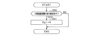
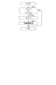
- FIG. 6 shows a processing procedure for controlling the interruption of the current flowing through the connection path 60, which is performed by the microcomputer 73. This control is repeatedly executed by the microcomputer 73, for example, at a predetermined control cycle.
- step S30 it is determined whether there is a request to execute three-phase short circuit control. If a negative determination is made in step S30, this process ends. On the other hand, if an affirmative determination is made in step S30, the process advances to step S31.
- step S31 the logic of the short circuit request signal Sg1 is switched to H.
- the logic H short circuit request signal Sg1 is input to the drive circuit 86, and the connection switch 61a is turned off.
- the current flowing through the connection path 60 is cut off.
- FIGS. 7 and 8 show an example of control when three-phase short circuit control is performed with the connection switch 61a turned on.
- FIG. 7 is a diagram showing the transition of each phase current Iu, Iv, and Iw before and after the three-phase short circuit control is performed
- FIG. 8 is a diagram showing an example of the current path formed during the three-phase short circuit control. It is a diagram. After time t1 in FIG. 7, the connection switch 61a is turned off and three-phase short circuit control is performed.
- a current path including the V-phase winding 41V, the V-phase lower arm switch QVL, the W-phase lower arm switch QWL, and the W-phase winding 41W is formed.
- electric current circulates between the rotating electric machine 40 and the inverter 30, thereby consuming electric power. This reduces the amplitude of each phase current Iu, Iv, and Iw.
- the battery pack 20 and the rotating electric machine 40 are not electrically connected by turning off the connection switch 61a, application of voltage to the battery pack 20 is suppressed.
- the connection switch 61a when the microcomputer 73 determines that there is a request to execute three-phase short circuit control, the connection switch 61a is turned off. This prevents the connection switch 61a from being turned on during the period in which the three-phase short circuit control is performed. Therefore, during the period in which the three-phase short circuit control is performed, it is possible to prevent the rotating electric machine 40 and the assembled battery 20 from being short-circuited via the connection path 60 and applying voltage to the first storage battery 21 and the second storage battery 22. Can be done. As a result, the first storage battery 21 and the second storage battery 22 can be prevented from being in an overvoltage state, and the reliability of the first storage battery 21 and the second storage battery 22 can be prevented from decreasing.
- the connection switch 61a is turned off and the leakage detection operation of the high voltage circuit is performed in a state where the three-phase short circuit control is performed.
- this high voltage circuit leakage detection operation it is possible to detect that a leakage occurs in a configuration closer to the rotating electrical machine 40 than the inverter 30. Therefore, a wider range of configurations can be subjected to earth leakage detection than when the earth leakage detection operation is performed with each of the switches QUH to QWL turned off.
- connection switch 61a is turned off during the period in which the three-phase short circuit control is performed, it is possible to suppress the reliability of the first storage battery 21 and the second storage battery 22 from decreasing as described above. That is, according to the present embodiment, the leakage detection operation can be appropriately performed while suppressing the reliability of the first storage battery 21 and the second storage battery 22 from decreasing.
- connection switch aims to shorten the period during which three-phase short circuit control is performed in a state where the connection switch is turned on.
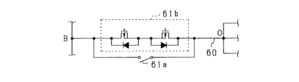
- the power conversion device 11 includes a connection switch 61b instead of the connection switch 61a of the first embodiment.
- the same components as those shown in FIG. 1 are given the same reference numerals for convenience.
- connection switch 61b of this embodiment is a switch that switches conduction and interruption of the current flowing through the connection path 60, and has a shorter turn-off time than the connection switch 61a of the first embodiment, and has a shorter turn-off time than the connection switch 61a of the first embodiment.
- This connection switch has a higher on-resistance than 61a.
- the connection switch 61b is a semiconductor switching element that conducts and cuts off current in both directions, and specifically includes a pair of IGBTs.
- the connection switch 61b is turned on and off by the drive circuit 86, similarly to the connection switch 61a of the first embodiment.
- connection switch 61b When the connection switch 61b is used, the current flowing through the connection path 60 is interrupted more quickly than when the connection switch 61a of the first embodiment is used, but the surge voltage generated due to the current interruption increases. there is a possibility. Therefore, there is a concern that the reliability of the connection switch 61b may deteriorate due to the high voltage being applied to the connection switch 61b.
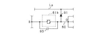
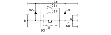
- the power conversion device 11 includes a first diode 91, a second diode 92, and a parallel capacitor 93.
- the anode of the first diode 91 is connected between the connection switch 61b and the neutral point O, and the cathode of the first diode 91 is connected to the positive bus Lp.
- the anode of the second diode 92 is connected between the connection switch 61b and the intermediate terminal B, and the cathode of the second diode 92 is connected to the positive bus Lp.
- the parallel capacitor 93 is provided in the connection path 60 and connected in parallel to the connection switch 61b.
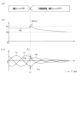
- FIG. 10 shows an example of control before and after three-phase short circuit control is performed.
- (a) shows the control state of the power converter 11
- (b) shows the transition of the terminal voltage VB of the assembled battery 20
- (c) shows the transition of each phase current Iu, Iv, Iw.
- the transition of the terminal voltage VB of the assembled battery 20 of this embodiment is shown by a solid line
- the transition of VBref is shown by a broken line.
- either the temperature increase control or the temperature increase motor drive control is performed. That is, before time t1, the connection switch 61b is turned on. At time t1, the microcomputer 73 determines that the terminal voltage VB of the assembled battery 20 exceeds the upper limit voltage V ⁇ , performs three-phase short circuit control, and turns off the connection switch 61b.
- the upper limit voltage V ⁇ is, for example, the upper limit voltage of the operating voltage range of the assembled battery 20.
- connection switch 61b is quickly turned off.
- the assembled battery 20 and the rotating electric machine 40 are electrically cut off, which is caused by the assembled battery 20 and the rotating electric machine 40 being connected via the connection path 60 during execution of the three-phase short circuit control. Therefore, application of voltage to the assembled battery 20 is suppressed. Therefore, for example, the terminal voltage VB of the assembled battery 20 gradually decreases to the terminal voltage V ⁇ when charging and discharging are stopped. In this case, an increase in the terminal voltage VB of the assembled battery 20 is more accurately suppressed than when a connection switch having a longer turn-off period than the connection switch 61b is used.
- connection switch 61b when a connection switch with a longer turn-off period than the connection switch 61b is used, the period during which the assembled battery 20 and the rotating electric machine 40 are connected via the connection path 60 is longer than when the connection switch 61b is used. Become. Therefore, the terminal voltage VBref of the battery pack 20 of the comparative example increases compared to the terminal voltage VB of the battery pack 20 of the present embodiment.
- transient currents Pu, Pv, Pw are superimposed on each phase current Iu, Iv, Iw.
- the first diode 91 and the second diode 92 ensure a path for the transient currents Pu, Pv, and Pw to circulate.
- the parallel capacitor 93 suppresses voltage changes caused by transient currents Pu, Pv, and Pw.
- connection path 60 is provided with a connection switch 61b.
- the period from when it is determined that there is a request to perform three-phase short circuit control until the connection switch 61b is turned off is shorter than when a switch with a longer turn-off period than the connection switch 61b is provided.
- the connection switch 61b is turned on, the period during which the three-phase short circuit control is performed becomes shorter than when a switch having a longer turn-off period than the connection switch 61b is provided. Therefore, it is possible to accurately suppress an increase in the terminal voltage VB of the assembled battery 20.
- connection switch 61b As the three-phase short circuit control is performed and the connection switch 61b is turned off, a surge voltage is generated. Due to the generation of the surge voltage, the transient currents Pu, Pv, Pw are superimposed on the phase currents Iu, Iv, Iw, and the voltage applied to the connection switch 61b may increase. As a result, there is a concern that the reliability of the connection switch 61b may deteriorate.
- connection path 60 the current flowing through the connection path 60 is circulated through the first diode 91 and the second diode 92.
- a parallel capacitor 93 is connected in parallel to the connection switch 61b. This suppresses changes in the voltage applied to the connection switch 61b due to the generation of transient currents Pu, Pv, and Pw. Therefore, three-phase short circuit control is performed, and when the connection switch 61b is turned off, an increase in the voltage applied to the connection switch 61b is suppressed. As a result, it is possible to prevent the reliability of the connection switch 61b from decreasing.
- Diodes are provided on both sides of the connection switch 61b. As a result, when the connection switch 61b is turned off and current is flowing in the direction from the neutral point O to the intermediate terminal B, the current flowing in the connection path 60 is circulated through the first diode 91. Ru. Further, when the connection switch 61b is turned off, if a current is flowing in the direction from the intermediate terminal B toward the neutral point O, the current flowing in the connection path 60 is circulated through the second diode 92. .
- connection switch 61b regardless of whether the direction of the current flowing through the connection path 60 is from the neutral point O to the intermediate terminal B or from the intermediate terminal B to the neutral point O, the first diode 91 and the second diode The current flowing through the connection path 60 is circulated through one of the connection paths 92. Therefore, when the connection switch 61b is turned off, it is possible to accurately suppress an increase in the voltage applied to the connection switch 61b.
- temperature increase control is performed while the connection switch 61b is turned on.
- the connection switch 61b since an alternating current flows in the connection path 60, the current flows in the connection path 60 both in the direction from the neutral point O to the intermediate terminal B and in the direction from the intermediate terminal B to the neutral point O. flows.
- the present embodiment in which diodes are provided on both sides of the connection switch 61b is a suitable configuration for suppressing an increase in the voltage applied to the connection switch 61b when the connection switch 61b is turned off.
- connection switch is changed.
- a configuration that achieves both high-speed interruption of the current flowing through the connection path 60 and reduction of conduction loss that occurs while the connection switch is turned on will be described.
- the power conversion device 11 includes a first connection switch 61a and a second connection switch 61b that are connected in parallel to each other.
- the first connection switch 61a is the connection switch 61a described in the first embodiment
- the second connection switch 61b is the connection switch 61b described in the second embodiment.
- the second connection switch 61b is provided in the connection path 60.
- the first connection switch 61a is connected in parallel to the second connection switch 61b. Note that in FIG. 11, the same components as those shown in FIGS. 1 and 9 are given the same reference numerals for convenience.
- FIG. 12 shows a processing procedure for switching control performed by the control device 70. This process is repeatedly executed by the control device 70, for example, at a predetermined control cycle.
- the same components as those shown in FIG. 2 are given the same reference numerals for convenience.
- step S40 the first connection switch 61a is turned off, and the second connection switch 61b is turned off. Thereby, intermediate terminal B and neutral point O are electrically disconnected.
- step S41 the process in step S41 is similar to the process in step S40.
- step S42 the first connection switch 61a is turned on, and the second connection switch 61b is turned off. After the process in step S42, the process advances to step S20.
- step S21 proceed to step S43.
- step S43 the first connection switch 61a is turned off, and the second connection switch 61b is turned on. After the process in step S43, the process advances to step S23.
- a second connection switch 61b is provided in the connection path 60, and the first connection switch 61a is connected in parallel to the second connection switch 61b.
- the second connection switch 61b is a connection switch that has a shorter turn-off time than the first connection switch 61a and has a higher on-resistance than the first connection switch 61a. be.
- either one of the first connection switch 61a and the second connection switch 61b is turned on depending on the operating conditions of the power converter 11, so that the current flowing through the connection path 60 is quickly interrupted and the connection switch is turned on. It becomes possible to simultaneously reduce conduction loss that occurs while the device is turned on.
- connection switch When the rotor of the rotating electric machine 40 is rotating, a back electromotive voltage is generated in each phase winding 41U, 41V, 41W, so if it is determined that there is a request to execute three-phase short circuit control, the connection switch It is desirable to turn it off immediately. On the other hand, in a situation where the rotation of the rotor of the rotating electric machine 40 is stopped, even if short circuit control is performed while the connection switch is turned on, it is considered that there is a low possibility that the assembled battery 20 will be in an overvoltage state. In this case, it is more desirable to reduce the conduction loss that occurs while the connection switch is on than to rapidly interrupt the current flowing through the connection path 60.
- the first connection switch 61a is turned off, the second connection switch 61b is turned on, and motor drive control or temperature increase motor drive control is performed.
- the second connection switch 61b which has a shorter turn-off period than the first connection switch 61a, is turned on.
- the second connection switch 61b can be turned off more quickly than when the first connection switch 61a is turned on.
- the current flowing through the connection path 60 can be interrupted more quickly.
- the first connection switch 61a is turned on and the second connection switch 61b is turned off.
- the temperature increase control is performed while the first connection switch 61a, which has a lower on-resistance than the second connection switch 61b, is turned on.
- the conduction loss that occurs while the first connection switch 61a is conducting can be reduced compared to the case of the second connection switch 61b.
- connection switch By changing the connection switch to be turned on depending on whether or not there is a request to drive the rotating electric machine 40, it is possible to quickly cut off the current flowing through the connection path 60 and reduce the conduction loss that occurs while the connection switch is turned on. It is possible to achieve both.
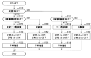
- FIG. 13 shows a control processing procedure performed by the control device 70. This process is repeatedly executed by the control device 70, for example, at a predetermined control cycle. Note that in FIG. 13, the same components as those shown in FIG. 12 are given the same reference numerals for convenience.
- step S44 voltage information regarding the back electromotive force generated in each phase winding 41U, 41V, and 41W is acquired.
- the voltage information is a detected value of the angle sensor 64.
- the voltage information is not limited to the detected value of the angle sensor 64, but may be the detected value of the phase current sensor 62, or may be based on at least one of the detected value of the phase current sensor 62 and the detected value of the angle sensor 64.
- the estimated value of the back electromotive force generated in each phase winding 41U, 41V, and 41W may be used.
- the process in step S44 is not limited to after the process in step S21, but may be performed, for example, after the process in step S10.
- step S45 based on the voltage information, it is determined whether the back electromotive force generated in each phase winding 41U, 41V, and 41W is below an allowable value.
- the rotational speed of the rotating electrical machine 40 is calculated based on the detected value of the angle sensor 64. It is determined whether the calculated rotational speed of the rotating electrical machine 40 is less than or equal to the allowable rotational speed.
- the allowable rotation speed may be set based on the withstand voltage of at least one of the assembled battery 20 and the smoothing capacitor 32. If it is determined that the calculated rotational speed of the rotating electrical machine 40 is below the allowable rotational speed, it is judged that the back electromotive force generated in each phase winding 41U, 41V, 41W is below the allowable value. If a negative determination is made in step S45, the process advances to step S43. On the other hand, if an affirmative determination is made in step S45, the process advances to step S46.
- step S44 when the detected value of the phase current sensor 62 is acquired as the voltage information, the effective value of each phase current Iu, Iv, Iw may be calculated based on the acquired detected value. In this case, it may be determined whether the calculated effective values of the phase currents Iu, Iv, and Iw are less than or equal to the allowable effective value. In addition, when the estimated value of the back electromotive force generated in each phase winding 41U, 41V, and 41W is obtained as voltage information, it is determined whether the obtained estimated value is less than or equal to the allowable back electromotive voltage. Good too.
- the allowable effective value and the allowable back electromotive voltage may be set based on the withstand voltage of at least one of the assembled battery 20 and the smoothing capacitor 32.
- step S46 the first connection switch 61a is turned on, and the second connection switch 61b is turned off. After the process in step S46, the process advances to step S23.
- the first connection switch 61a is turned on, and the second connection switch 61b is turned off. In this case, the first connection switch 61a, which has a lower on-resistance than the second connection switch 61b, is turned on.
- connection switch even if the rotor of the rotating electric machine 40 is rotating, if it is determined that there is a low possibility that the assembled battery 20 will be in an overvoltage state, the current flowing through the connection path 60 is quickly cut off, and the connection Among the reductions in conduction losses that occur while the switch is on, priority can be given to reducing the conduction losses of the connection switch.
- FIG. 14 shows the configuration of the control device 70.
- the same components as those shown in FIG. 3 are given the same reference numerals for convenience.
- the determination unit 81 switches the logic of the cutoff signal Sgf from L to H.
- the cutoff signal Sgf is a signal indicating whether there is a request to turn off the first connection switch 61a. Specifically, when the logic of the cutoff signal Sgf is L, it indicates that there is no request to turn off the first connection switch 61a, and when the logic of the cutoff signal Sgf is H, there is a request to turn off the first connection switch 61a. Show that there is.
- a cutoff signal Sgf is input to the drive circuit 86 instead of the short circuit request signal Sg1.
- the drive circuit 86 turns off the first connection switch 61a when the logic H cutoff signal Sgf is input. Further, when the logic L cutoff signal Sgf is input, the drive circuit 86 maintains the first connection switch 61a on/off as it is.
- FIG. 15 shows the procedure of the process performed by the determination unit 81. This process is repeatedly executed by the determination unit 81, for example, at a predetermined control cycle.
- step S50 it is determined whether three-phase short circuit control is to be performed. In this embodiment, it is determined whether at least one of the condition that the logic of the short circuit request signal Sg1 is H and the condition that the lower arm drive voltage VdL is lower than the predetermined voltage Vp is satisfied. . If a negative determination is made in step S50, this process ends. On the other hand, if an affirmative determination is made in step S50, the process advances to step S51.
- step S51 the logic of the cutoff signal Sgf is switched to H.
- the logic H cutoff signal Sgf is input to the drive circuit 86, and the first connection switch 61a is turned off.
- the current flowing through the connection path 60 is cut off.
- step S52 three-phase short circuit control is implemented. Specifically, an ON command for each of the lower arm switches QUH to QWH is output to the lower arm driver 76. Thereby, three-phase short circuit control is performed.
- the switching control performed while the first connection switch 61a is turned on is not limited to temperature increase control and temperature increase motor drive control.
- the control device 70 may perform energy management control while the first connection switch 61a is turned on.
- the control device 70 controls the first storage battery 21 and the second storage battery 21 through the switching device section 31, each phase winding 41U, 41V, 41W, and the connection path 60 in a state where the first connection switch 61a is turned on.
- Each of the switches QUH to QWL is turned on and off so that direct current flows between the storage batteries 22. Thereby, electric power is transferred from one of the first storage battery 21 and the second storage battery 22 to the other.
- energy management control is performed instead of temperature increase control
- the process described above with reference to FIG. 2 may be changed as follows.
- energy management control a case will be described in which equalization control is performed for the purpose of equalizing the terminal voltage VH of the first storage battery 21 and the terminal voltage VL of the second storage battery 22.
- step S10 instead of determining whether there is a temperature increase request, it is preferable to determine whether there is a request for equalization of the terminal voltage VH of the first storage battery 21 and the terminal voltage VL of the second storage battery 22. . Specifically, when it is determined that the absolute value of the difference between the terminal voltage VH of the first storage battery 21 and the terminal voltage VL of the second storage battery 22 exceeds a predetermined value, it is determined that there is an equalization request.
- step S18 equalization control may be performed instead of temperature increase control.
- step S20 in the PWM process of equalization control, it is preferable to calculate the U, V, and W phase modulation factors based on the terminal voltage VH of the first storage battery 21 and the terminal voltage VL of the second storage battery 22. Specifically, the determination voltage is calculated by subtracting the terminal voltage VL of the second storage battery 22 from the terminal voltage VH of the first storage battery 21. If the calculated determination voltage is a positive value, the neutral point command current is set to a positive value. On the other hand, if the calculated determination voltage is a negative value, the neutral point command current is set to a negative value.
- a process may be performed in which the larger the absolute value of the determination voltage is, the larger the absolute value of the neutral point command current is set.
- the neutral point command current in this embodiment is a direct current.
- the PWM processing after the neutral point command current is set is the same as in the case of temperature increase control.
- equalization motor drive control may be performed instead of temperature raising motor drive control.
- PWM control in step S23 it is preferable to calculate the U, V, and W phase modulation factors based on the torque command value of the rotating electrical machine 40, the terminal voltage VH of the first storage battery 21, and the terminal voltage VL of the second storage battery 22.
- the neutral point command current may be set as in the case of equalization control.
- - Energy management control does not aim at equalizing the terminal voltage VH of the first storage battery 21 and the terminal voltage VL of the second storage battery 22, but rather controls the exchange of energy between the first storage battery 21 and the second storage battery 22. May be done.
- either one of the first storage battery 21 and the second storage battery 22 can be connected to a charger provided outside the power conversion system 10. This assumes a situation where In this situation, a situation is assumed in which power is transferred from one of the first storage battery 21 and the second storage battery 22 that is charged by the charger to the other storage battery.
- the connection path 60 has either one of the directions from the neutral point O to the intermediate terminal B, and from the intermediate terminal B to the neutral point O. Current flows in the direction. Specifically, by performing energy management control in which power is transferred from the first storage battery 21 to the second storage battery 22, a current flows in the connection path 60 in the direction from the neutral point O to the intermediate terminal B. flows. Furthermore, when energy management control is performed in which power is transferred from the second storage battery 22 to the first storage battery 21, a current flows in the connection path 60 in a direction from the intermediate terminal B toward the neutral point O.
- the second connection switch 61b is a semiconductor switching element that conducts and interrupts current in one direction instead of a semiconductor switching element that conducts and interrupts current in both directions. It may be an element. As described above, when the second connection switch 61b is a semiconductor switching element that conducts and interrupts current in one direction, one of the first storage battery 21 and the second storage battery 22 is used as an energy management control. It is assumed that control is performed in which power is sent and received only to the other party.
- a semiconductor when power is transferred and received from the first storage battery 21 to the second storage battery 22 as energy management control, a semiconductor conducts and interrupts current flowing from the neutral point O toward the intermediate terminal B.
- a switching element may be used.
- 16 and 17 show a configuration in which an IGBT that conducts and interrupts current flowing in a direction from the neutral point O toward the intermediate terminal B is used as the second connection switch 61b.
- control is performed to transfer power from the second storage battery 22 to the first storage battery 21 as energy management control
- conduction and interruption of the current flowing in the direction from the intermediate terminal B toward the neutral point O is performed.
- 18 and 19 show a configuration in which an IGBT that conducts and interrupts the current flowing in the direction from the intermediate terminal B toward the neutral point O is used as the second connection switch 61b.
- the second connection switch 61b may be an N-channel MOSFET instead of the IGBT.
- FIG. 20 shows an example in which the second connection switch 61b in the configuration shown in FIG. 9 is composed of a pair of N-channel MOSFETs whose sources are connected to each other. Further, as shown in FIG. 21, in the configuration shown in FIG. 11, the second connection switch 61b may be a pair of N-channel MOSFETs whose sources are connected to each other instead of the IGBT.
- At least one of the first diode 91 and the second diode 92 may not be provided.
- a current flows in the connection path 60 in the direction from the neutral point O to the intermediate terminal B.
- the second diode 92 may not be provided.
- a current flows in a direction from the intermediate terminal B toward the neutral point O.
- the first diode 91 may not be provided.
- the power converter 11 it is omitted to provide the power converter 11 with a diode depending on the execution mode of energy management control. Thereby, it is possible to reduce the number of diodes included in the power conversion device 11 and to suppress an increase in the voltage applied to the connection switch 61b.
- the parallel capacitor 93 may not be provided.
- the first embodiment and its modifications, the second embodiment and its modifications, the third embodiment and its modifications, and the fourth embodiment may be combined and implemented.
- the second embodiment and the third embodiment in combination as shown in FIG. It is also possible to adopt a configuration including two diodes 92 and a parallel capacitor 93.
- the configurations shown in FIGS. 25, 26, and 27 may be used.
- the power conversion device 11 includes a first connection switch 61a, a second connection switch 61b, a second diode 92, and a parallel capacitor 93.
- FIG. 25 the power conversion device 11 includes a first connection switch 61a, a second connection switch 61b, a second diode 92, and a parallel capacitor 93.
- the power conversion device 11 includes a first connection switch 61a, a second connection switch 61b, a first diode 91, and a parallel capacitor 93.
- the power conversion device 11 includes a first connection switch 61a, a second connection switch 61b, a first diode 91, and a second diode 92.
- the control device 70 may control to turn on each of the upper arm switches QUH to QWH and turn off each of the lower arm switches QUL to QWL as three-phase short circuit control.
- the upper and lower arm switches constituting the switching device section 31 are not limited to IGBTs, and may be, for example, N-channel MOSFETs. In this case, the high potential side terminal becomes the drain, and the low potential side terminal becomes the source.
- the power conversion system 10 may be mounted on a moving object such as an aircraft or a ship, without being limited to a vehicle.
- the rotating electric machine 40 serves as a flight power source for the aircraft, and when the moving body is a ship, the rotating electric machine 40 serves as a navigation power source for the vessel.
- the installation destination of the power conversion system 10 is not limited to a mobile body.
- FIG. 1 a rotating electrical machine (40) having star-connected windings (41U, 41V, 41W); A power conversion device (11) comprising an inverter (30) having a series connection of upper arm switches (QUH, QVH, QWH) and lower arm switches (QUL, QVL, QWL), A connection that electrically connects the negative electrode side of the first storage battery and the positive electrode side of the second storage battery to the neutral point of the winding in a first storage battery (21) and a second storage battery (22) connected in series.
- a power conversion device (11) comprising an inverter (30) having a series connection of upper arm switches (QUH, QVH, QWH) and lower arm switches (QUL, QVL, QWL), A connection that electrically connects the negative electrode side of the first storage battery and the positive electrode side of the second storage battery to the neutral point of the winding in a first storage battery (21) and a second storage battery (22) connected in series.
- a route (60) It is provided in the connection path, and when turned on, electrically connects the negative electrode side of the first storage battery and the positive electrode side of the second storage battery to the neutral point, and when turned off, it electrically connects the neutral point of the first storage battery.
- connection switch (61a, 61b) that electrically disconnects the negative electrode side and the positive electrode side of the second storage battery from the neutral point; a control unit (70) that controls switching of the upper arm switch and the lower arm switch while turning on the connection switch; a determination unit (73, 81) that determines whether to perform short-circuit control in which one of the upper arm switch and the lower arm switch is turned on and the other is turned off;
- a power conversion device comprising: a cutoff section (86) that turns off the connection switch when it is determined that the short circuit control is to be performed.
- connection switch is a first connection switch (61a) and a second connection switch (61b) that are connected in parallel to each other,
- the control unit includes: Determining whether there is a drive request to rotationally drive the rotor of the rotating electric machine, If it is determined that there is the drive request, performing the switching control while turning on the second connection switch of the first connection switch and the second connection switch; The power conversion device according to configuration 2, in which, when it is determined that there is no drive request, the switching control is performed while turning on the first connection switch among the first connection switch and the second connection switch.
- the control unit includes: Obtaining voltage information regarding the back electromotive force generated in the winding, If it is determined that there is the drive request, it is determined based on the voltage information whether a back electromotive force generated in the winding is below a permissible value; If it is determined that the back electromotive force generated in the winding is equal to or less than the allowable value, the switching control is performed while turning on the first connection switch among the first connection switch and the second connection switch.
- the diodes are a first diode (91) and a second diode (92),
- the anode of the first diode is electrically connected between the connection switch and the neutral point
- the cathode of the first diode is electrically connected to the high potential side terminal of the upper arm switch
- the anode of the second diode is electrically connected between the connection switch and the negative electrode side of the first storage battery and the positive electrode side of the second storage battery
- the cathode of the second diode is connected between the connection switch and the negative electrode side of the first storage battery and the positive electrode side of the second storage battery.
- the power conversion device according to configuration 5, which is electrically connected to the high potential side terminal.
Landscapes
- Engineering & Computer Science (AREA)
- Power Engineering (AREA)
- Control Of Ac Motors In General (AREA)
- Inverter Devices (AREA)
- Electric Propulsion And Braking For Vehicles (AREA)
Priority Applications (3)
| Application Number | Priority Date | Filing Date | Title |
|---|---|---|---|
| EP23846161.0A EP4564659A4 (en) | 2022-07-29 | 2023-07-05 | POWER CONVERSION DEVICE |
| CN202380056044.3A CN119654785A (zh) | 2022-07-29 | 2023-07-05 | 电力转换装置 |
| JP2024536903A JP7828456B2 (ja) | 2022-07-29 | 2023-07-05 | 電力変換装置、プログラム |
Applications Claiming Priority (2)
| Application Number | Priority Date | Filing Date | Title |
|---|---|---|---|
| JP2022-122122 | 2022-07-29 | ||
| JP2022122122 | 2022-07-29 |
Publications (1)
| Publication Number | Publication Date |
|---|---|
| WO2024024428A1 true WO2024024428A1 (ja) | 2024-02-01 |
Family
ID=89706153
Family Applications (1)
| Application Number | Title | Priority Date | Filing Date |
|---|---|---|---|
| PCT/JP2023/024915 Ceased WO2024024428A1 (ja) | 2022-07-29 | 2023-07-05 | 電力変換装置 |
Country Status (4)
| Country | Link |
|---|---|
| EP (1) | EP4564659A4 (https=) |
| JP (1) | JP7828456B2 (https=) |
| CN (1) | CN119654785A (https=) |
| WO (1) | WO2024024428A1 (https=) |
Cited By (5)
| Publication number | Priority date | Publication date | Assignee | Title |
|---|---|---|---|---|
| US12282014B2 (en) | 2015-11-19 | 2025-04-22 | Dana-Farber Cancer Institute, Inc. | Methods of identifying compounds that interfere with ERG-driven misguidance of BAF complexes in TMPRSS2-ERG driven prostate cancers |
| US12383555B2 (en) | 2020-05-20 | 2025-08-12 | Foghorn Therapeutics Inc. | Methods of treating cancers |
| US12383560B2 (en) | 2018-01-30 | 2025-08-12 | Foghorn Therapeutics Inc. | Compounds and uses thereof |
| US12509453B2 (en) | 2019-01-29 | 2025-12-30 | Foghorn Therapeutics Inc. | BRM/BRG1 inhibitors and uses thereof |
| US12606553B2 (en) | 2021-03-09 | 2026-04-21 | Foghorn Therapeutics Inc. | Crystalline forms, compositions containing same, and methods of their use |
Citations (4)
| Publication number | Priority date | Publication date | Assignee | Title |
|---|---|---|---|---|
| WO2016136815A1 (ja) * | 2015-02-25 | 2016-09-01 | 本田技研工業株式会社 | 電力システム |
| WO2021065222A1 (ja) * | 2019-10-03 | 2021-04-08 | 株式会社Soken | 電力変換装置 |
| JP2021093845A (ja) | 2019-12-10 | 2021-06-17 | 株式会社Soken | 電力変換装置 |
| JP2021191074A (ja) * | 2020-05-28 | 2021-12-13 | 日立Astemo株式会社 | インバータ制御装置 |
-
2023
- 2023-07-05 EP EP23846161.0A patent/EP4564659A4/en active Pending
- 2023-07-05 JP JP2024536903A patent/JP7828456B2/ja active Active
- 2023-07-05 WO PCT/JP2023/024915 patent/WO2024024428A1/ja not_active Ceased
- 2023-07-05 CN CN202380056044.3A patent/CN119654785A/zh active Pending
Patent Citations (4)
| Publication number | Priority date | Publication date | Assignee | Title |
|---|---|---|---|---|
| WO2016136815A1 (ja) * | 2015-02-25 | 2016-09-01 | 本田技研工業株式会社 | 電力システム |
| WO2021065222A1 (ja) * | 2019-10-03 | 2021-04-08 | 株式会社Soken | 電力変換装置 |
| JP2021093845A (ja) | 2019-12-10 | 2021-06-17 | 株式会社Soken | 電力変換装置 |
| JP2021191074A (ja) * | 2020-05-28 | 2021-12-13 | 日立Astemo株式会社 | インバータ制御装置 |
Non-Patent Citations (1)
| Title |
|---|
| See also references of EP4564659A4 |
Cited By (5)
| Publication number | Priority date | Publication date | Assignee | Title |
|---|---|---|---|---|
| US12282014B2 (en) | 2015-11-19 | 2025-04-22 | Dana-Farber Cancer Institute, Inc. | Methods of identifying compounds that interfere with ERG-driven misguidance of BAF complexes in TMPRSS2-ERG driven prostate cancers |
| US12383560B2 (en) | 2018-01-30 | 2025-08-12 | Foghorn Therapeutics Inc. | Compounds and uses thereof |
| US12509453B2 (en) | 2019-01-29 | 2025-12-30 | Foghorn Therapeutics Inc. | BRM/BRG1 inhibitors and uses thereof |
| US12383555B2 (en) | 2020-05-20 | 2025-08-12 | Foghorn Therapeutics Inc. | Methods of treating cancers |
| US12606553B2 (en) | 2021-03-09 | 2026-04-21 | Foghorn Therapeutics Inc. | Crystalline forms, compositions containing same, and methods of their use |
Also Published As
| Publication number | Publication date |
|---|---|
| EP4564659A1 (en) | 2025-06-04 |
| CN119654785A (zh) | 2025-03-18 |
| JP7828456B2 (ja) | 2026-03-11 |
| JPWO2024024428A1 (https=) | 2024-02-01 |
| EP4564659A4 (en) | 2025-11-05 |
Similar Documents
| Publication | Publication Date | Title |
|---|---|---|
| JP7828456B2 (ja) | 電力変換装置、プログラム | |
| JP7613905B2 (ja) | 制御装置、プログラム、及び制御方法 | |
| CN110063012B (zh) | 逆变器控制装置 | |
| CN103348586B (zh) | 逆变器装置和逆变器控制方法 | |
| US12249937B2 (en) | Rotating electrical machine control system | |
| CN111095778B (zh) | 逆变器控制装置 | |
| KR101831468B1 (ko) | 삼상 이상의 전기 기기를 포함하는 차량 내 구동 어셈블리의 작동 방법 및 인버터용 제어 장치 | |
| US10479206B2 (en) | Method for switching an operating state of an electric machine and device for switching an operating state of an electric machine | |
| JP2015198462A (ja) | インバータ制御装置 | |
| JP2015198463A (ja) | インバータ制御装置 | |
| JP2016131426A (ja) | 電力変換装置 | |
| WO2022168868A1 (ja) | 回転電機制御システム | |
| JP2020005389A (ja) | 電源システム | |
| JP2021129399A (ja) | 電力変換器の制御回路 | |
| JP7474045B2 (ja) | 回転電機システム | |
| CN115622471A (zh) | 马达驱动系统 | |
| JP7277348B2 (ja) | 電力変換装置 | |
| US20260058571A1 (en) | Three-level inverter and storage medium | |
| JP7446358B2 (ja) | 交流回転電機の制御装置 | |
| JP7631745B2 (ja) | インバータ制御装置、プログラム | |
| WO2025134731A1 (ja) | 回転電機の制御装置、プログラム、及び回転電機の制御方法 | |
| WO2025158895A1 (ja) | 回転電機の制御装置、プログラム、及び回転電機の制御方法 | |
| JP2023052706A (ja) | モータ駆動回路 | |
| WO2025142363A1 (ja) | 回転電機の制御装置、プログラム、及び回転電機の制御方法 | |
| JP2025182399A (ja) | 回転電機システムの制御装置、プログラム、及び回転電機システムの制御方法 |
Legal Events
| Date | Code | Title | Description |
|---|---|---|---|
| 121 | Ep: the epo has been informed by wipo that ep was designated in this application |
Ref document number: 23846161 Country of ref document: EP Kind code of ref document: A1 |
|
| WWE | Wipo information: entry into national phase |
Ref document number: 2024536903 Country of ref document: JP |
|
| WWE | Wipo information: entry into national phase |
Ref document number: 202380056044.3 Country of ref document: CN |
|
| WWE | Wipo information: entry into national phase |
Ref document number: 202517012252 Country of ref document: IN |
|
| WWE | Wipo information: entry into national phase |
Ref document number: 2023846161 Country of ref document: EP |
|
| NENP | Non-entry into the national phase |
Ref country code: DE |
|
| ENP | Entry into the national phase |
Ref document number: 2023846161 Country of ref document: EP Effective date: 20250228 |
|
| WWP | Wipo information: published in national office |
Ref document number: 202517012252 Country of ref document: IN |
|
| WWP | Wipo information: published in national office |
Ref document number: 202380056044.3 Country of ref document: CN |
|
| WWP | Wipo information: published in national office |
Ref document number: 2023846161 Country of ref document: EP |