WO2024024051A1 - 無線通信システム、通信経路制御装置、通信経路制御方法および通信経路制御用プログラム - Google Patents
無線通信システム、通信経路制御装置、通信経路制御方法および通信経路制御用プログラム Download PDFInfo
- Publication number
- WO2024024051A1 WO2024024051A1 PCT/JP2022/029168 JP2022029168W WO2024024051A1 WO 2024024051 A1 WO2024024051 A1 WO 2024024051A1 JP 2022029168 W JP2022029168 W JP 2022029168W WO 2024024051 A1 WO2024024051 A1 WO 2024024051A1
- Authority
- WO
- WIPO (PCT)
- Prior art keywords
- communication
- route
- qos
- wireless terminal
- stations
- Prior art date
- Legal status (The legal status is an assumption and is not a legal conclusion. Google has not performed a legal analysis and makes no representation as to the accuracy of the status listed.)
- Ceased
Links
Images


Classifications
-
- H—ELECTRICITY
- H04—ELECTRIC COMMUNICATION TECHNIQUE
- H04W—WIRELESS COMMUNICATION NETWORKS
- H04W40/00—Communication routing or communication path finding
- H04W40/02—Communication route or path selection, e.g. power-based or shortest path routing
- H04W40/12—Communication route or path selection, e.g. power-based or shortest path routing based on transmission quality or channel quality
-
- H—ELECTRICITY
- H04—ELECTRIC COMMUNICATION TECHNIQUE
- H04W—WIRELESS COMMUNICATION NETWORKS
- H04W28/00—Network traffic management; Network resource management
- H04W28/02—Traffic management, e.g. flow control or congestion control
- H04W28/0268—Traffic management, e.g. flow control or congestion control using specific QoS parameters for wireless networks, e.g. QoS class identifier [QCI] or guaranteed bit rate [GBR]
-
- H—ELECTRICITY
- H04—ELECTRIC COMMUNICATION TECHNIQUE
- H04W—WIRELESS COMMUNICATION NETWORKS
- H04W84/00—Network topologies
- H04W84/18—Self-organising networks, e.g. ad-hoc networks or sensor networks
- H04W84/22—Self-organising networks, e.g. ad-hoc networks or sensor networks with access to wired networks
-
- H—ELECTRICITY
- H04—ELECTRIC COMMUNICATION TECHNIQUE
- H04W—WIRELESS COMMUNICATION NETWORKS
- H04W84/00—Network topologies
- H04W84/02—Hierarchically pre-organised networks, e.g. paging networks, cellular networks, WLAN [Wireless Local Area Network] or WLL [Wireless Local Loop]
- H04W84/04—Large scale networks; Deep hierarchical networks
- H04W84/06—Airborne or Satellite Networks
Definitions
- This disclosure relates to a wireless communication system, a communication route control device, a communication route control method, and a communication route control program, and in particular, a wireless communication system suitable for enabling efficient wireless communication using a non-terrestrial network. , relates to a communication route control device, a communication route control method, and a communication route control program.
- NTN non-terrestrial networks
- UAVs unmanned aerial vehicles
- HAPS high-altitude pseudo-satellites
- FIG 1 shows an example of an NTN consisting of a HAPS network.
- An unmanned flying vehicle (hereinafter referred to as a flying vehicle) 10 has a function of irradiating a beam onto the ground to form a mobile service area.
- a ground wireless terminal (hereinafter referred to as UE: User Equipment) 14 existing within the service area 12 connects to the HAPS aircraft 10 and connects to the ground base station 16 via the aircraft 10.
- the aircraft 10 is equipped with a signal relay function. Packets transmitted from the UE 14 are sent to the data network 20 via the aircraft 10, the ground base station 16, and the mobile network 18. Packets destined for the UE 14 from the data network 20 are also relayed in the same way.
- Figure 2 shows an example of an NTN consisting of geostationary orbit satellites (GEO satellites), low earth orbit satellites (LEO satellites), and a HAPS network.
- GEO satellites geostationary orbit satellites
- LEO satellites low earth orbit satellites
- HAPS network a HAPS network
- the satellites 22, 24 and the aircraft 10 belonging to each network connect links with each other to form a network.
- the satellites 22, 24 and the aircraft 10 have a routing function, and the traffic transmitted from the UE 14 is transferred by them and sent to the Internet network.
- traffic generated between the UE 14 and the Internet will be routed to each satellite 22, 24 in the GEO or LEO satellite network or the aircraft 10 in the HAPS network as nodes. Ru.
- Each of these networks has different characteristics. Table 1 shows the characteristics of each network.
- the altitudes of the flying object 10 and the satellites 22 and 24 are different, and there is a large difference in signal propagation delay depending on which route they take.
- the GEO satellite 24 exists at an altitude of about 36,000 km, it takes at least about 120 ms for the signal transmitted from the UE 14 to arrive at the satellite 24, although it depends on the elevation angle.
- the aircraft 10 of the HAPS network exists at an altitude of about 20 km, the time it takes for the signal transmitted from the UE 14 to arrive at the aircraft 10 is about 0.07ms, which is longer than when the signal goes via the GEO satellite 24. Low delay.
- the bandwidth of the link between the nodes of the satellites 22, 24 and the aircraft 10 may also differ. There is sex.
- the following non-patent document 1 proposes a routing method that takes into consideration the propagation delay time due to the distance between the satellite/aircraft node, the bandwidth of the link between the satellite/aircraft node, and the like.
- the mobile communication system UE14 is used for a wide variety of applications, including voice calls, video transmission, and IoT communication using sensors.
- the required QoS Quality of Service
- the required transmission speed and allowable latency differ depending on the application. For example, voice calls require low latency, and video transmission requires a certain high transmission speed, although this depends on image quality and other factors.
- E2E End to End
- traffic can flow through various routes from the satellites 22, 24 or the aircraft 10 to which the UE 14 connects to the mobile network 18 on the ground. Since the propagation delay times and bands between nodes such as the satellites 22 and 24 and the flying object 10 differ, it is necessary to set a route suitable for the required QoS. Furthermore, if a transmission speed above a certain level is required as the required QoS, it is necessary to secure a band that satisfies the requirement in the link connecting the satellites 22, 24 and the aircraft 10 included in the set route.
- Non-Patent Document 1 does not take into account the QoS required by the application used by the UE 14. Furthermore, this technology performs routing control to select the optimal link for each link, and does not calculate a route overlooking E2E. Therefore, the technique described in Non-Patent Document 1 cannot necessarily satisfy the QoS required by E2E.
- the present disclosure has been made in view of the above-mentioned problems, and its primary purpose is to provide a wireless communication system that sets a route that satisfies the QoS required for each application used in a wireless terminal in a non-terrestrial network using E2E. 1 purpose.
- a second object of the present disclosure is to provide a communication path control device that sets a route that satisfies the QoS required for each application used in a wireless terminal in E2E in a non-terrestrial network.
- a third objective of the present disclosure is to provide a communication path control method for setting a route that satisfies the QoS required for each application used in a wireless terminal in E2E in a non-terrestrial network.
- a fourth objective of the present disclosure is to provide a communication path control program for setting a route that satisfies the QoS required for each application used in a wireless terminal in E2E in a non-terrestrial network.
- a first aspect configures a network in which a plurality of communication stations link to each other and transfer packets, and the plurality of communication stations perform connection communication that provides a service area to wireless terminals.
- a wireless communication system including a station, wherein the wireless terminal connects to the connecting communication station and transmits and receives packets to and from a data network, QoS collection processing for collecting requested QoS information corresponding to the service type of the wireless terminal; quality prediction processing for predicting communication quality in links between the plurality of communication stations; a route determination process that determines a communication route based on the communication quality so that the required QoS is satisfied between the connected communication station and the data network; distributing a routing table including traffic transfer destination information to at least communication stations included in the communication route; comprising a control station configured to perform It is preferable that a communication station included in the communication path is configured to transfer packets between the wireless terminal and the data network according to the routing table.
- a plurality of communication stations constitute a network in which a plurality of communication stations are linked to each other and transfer packets, and the plurality of communication stations include a connecting communication station that provides a service area to a wireless terminal, and the plurality of communication stations include a connecting communication station that provides a service area to a wireless terminal;
- a communication path control device that controls a communication path when a terminal connects to the connection communication station and transmits and receives packets to and from a data network, QoS collection processing for collecting requested QoS information corresponding to the service type of the wireless terminal; quality prediction processing for predicting communication quality in links between the plurality of communication stations; a route determination process that determines a communication route based on the communication quality so that the required QoS is satisfied between the connected communication station and the data network; distributing a routing table including traffic transfer destination information to at least communication stations included in the communication route; It is preferable that the system be configured to run .
- a plurality of communication stations constitute a network in which a plurality of communication stations are linked to each other and transfer packets, and the plurality of communication stations include a connecting communication station that provides a service area to a wireless terminal, and the plurality of communication stations include a connecting communication station that provides a service area to a wireless terminal, and
- a communication path control method for controlling a communication path when a terminal connects to the connecting communication station and transmits and receives packets to and from a data network comprising: a QoS collection step of collecting requested QoS information corresponding to the service type of the wireless terminal; a quality prediction step of predicting communication quality in links between the plurality of communication stations; a route determining step of determining a communication route based on the communication quality so that the required QoS is satisfied between the connected communication station and the data network; distributing a routing table containing traffic forwarding destination information to at least communication stations included in the communication route; a step in which a communication station included in the communication path transfers packet
- a plurality of communication stations constitute a network in which a plurality of communication stations link to each other and transfer packets, and the plurality of communication stations include a connecting communication station that provides a service area to a wireless terminal, and the plurality of communication stations include a connecting communication station that provides a service area to a wireless terminal, and A communication path control program for controlling a communication path when a terminal connects to the connecting communication station and transmits/receives packets to/from a data network, the program comprising: to the processor unit, QoS collection processing for collecting requested QoS information corresponding to the service type of the wireless terminal; quality prediction processing for predicting communication quality in links between the plurality of communication stations; a route determination process that determines a communication route based on the communication quality so that the required QoS is satisfied between the connected communication station and the data network; distributing a routing table including traffic transfer destination information to at least communication stations included in the communication route; It is desirable to include a program that executes.
- FIG. 2 is a diagram showing an example of an NTN configured from a HAPS network.
- FIG. 2 is a diagram showing an example of an NTN composed of a geostationary orbit satellite, a low orbit satellite, and a HAPS network.
- 1 is a diagram showing the configuration of a wireless communication system according to Embodiment 1 of the present disclosure.
- 4 is a flowchart for explaining the flow of processing executed in the wireless communication system shown in FIG. 3.
- FIG. FIG. 2 is a diagram for explaining an example of the operation of the wireless communication system according to Embodiment 1 of the present disclosure.
- 12 is a flowchart for explaining the operation of the wireless communication system according to Embodiment 3 of the present disclosure.
- FIG. 7 is a diagram for explaining an example of the operation of the wireless communication system according to Embodiment 6 of the present disclosure.
- FIG. 3 shows a wireless communication system according to Embodiment 1 of the present disclosure.
- the wireless communication system of this embodiment includes a GEO satellite 24, a LEO satellite 22, a flying object 10, a UE 14, a ground base station 16, a mobile core network 18, and a route control device 26.
- GEO satellite 24, LEO satellite 22, and flying vehicle 10 form a service area 12 with respect to the ground as part of a GEO satellite network, a LEO satellite network, and a HAPS network, respectively.
- the aircraft 10 is equipped with a base station function and can accommodate the UEs 14 within the service area 12 and connect them to the network. Further, the satellites 22 and 24 and the flying object 10 are equipped with a link function and a routing function for relaying signals. The satellites 22 , 24 and the aircraft 10 establish a network by establishing connection links between them, and relay transmission and reception signals between the UE 14 within the service area 12 and the mobile core network 18 .
- the UE 14 is compatible with a mobile communication system, connects to the data network 20 via the HAPS network configured by the aircraft 10, and executes various communication applications.
- the ground base station 16 transmits and receives signals between the satellites 22, 24 and the aircraft 10 and the mobile core network 18 on the ground.
- the mobile core network 18 performs management of the connected UE 14, mobility control such as handover, transmission/reception session control, etc. Mobile core network 18 further transfers packets between UE 14 and data network 20.
- the system of this embodiment includes a route control device 26 as part of the mobile core network 18.
- the route control device 26 derives the effective transmission rate etc. from information such as propagation delay time according to the distance of each link and the band used by each link. Then, based on the derived results, the route control device 26 selects a route between the mobile core network 18 and the satellites 22, 24 or the aircraft 10 to which the UE 14 is connected for each session. and distributes a routing table for route setting to the aircraft 10.
- the route control device 26 can be configured by combining dedicated hardware.
- the route control device 26 may be configured by hardware including a processor unit and a memory device.
- the desired function may be realized by storing a dedicated communication path control program in the memory device and having the processor unit execute the program.
- FIG. 4 is a flowchart for explaining the flow of processing executed in the system of this embodiment.
- the UE 14 connected to the network notifies the mobile core network 18 of the service type of the application to be used (step 100).
- the route control device 26 included in the mobile core network 18 selects a route to be used (step 102). Specifically, the connection between the satellites 22, 24 or the aircraft 10 to which the UE 14 is connected and the mobile core network 18 is based on the service type of the application, the link information between the satellites 22, 24, the aircraft 10, etc. A route is calculated or selected for the session between.
- the route control device 26 distributes a routing table to the satellites 22, 24 and the aircraft 10 so that the route selected by the above process is used (step 104).
- the mobile core network 18 sets up a session between the satellites 22, 24 or the aircraft 10 to which the UE 14 is connected and the mobile core network 18 (step 106).
- the mobile core network 18 issues transmission control commands to the satellites 22, 24 and the aircraft 10 included in the set session route in order to satisfy the required transmission speed required by the QoS.
- the transmission control command includes a command requesting the satellites 22, 24 and the flying object 10 to guarantee the bandwidth necessary to satisfy QoS.
- the satellites 22, 24 and the flying object 10 receive the above command, they perform transmission control such as transmission scheduling and priority transmission so that the band guarantee is satisfied.
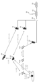
- FIG. 5 shows an example of a network assumed to explain the operation of the system of this embodiment.
- the GEO satellite network and the LEO satellite network are each composed of one GEO satellite 24 and one LEO satellite 22.
- the HAPS network includes three aircraft 10. This network uses IP-based packet routing. It is assumed that IP addresses are assigned to the satellites 22, 24, the flying object 10, the router 28, and the like. Table 2 shows examples of IP addresses assigned to each element.
- each link there are four links between the satellites 22, 24 and the aircraft 10.
- the bandwidth and propagation delay of each link depend on the performance of the communication devices mounted on the satellites 22, 24 and the flying object 10, the distance of the link, etc., and can be specified based on known information.
- Table 3 shows an example of the bandwidth and propagation delay of each link.
- LEO satellite 22 moves relative to the flying object 10 constituting the HAPS and the GEO satellite 24. Therefore, a plurality of LEO satellites 22 in orbit are used for communication in a sequential manner. As a result, link 1 connecting GEO satellite 24 and LEO satellite 22, and link 2 connecting aircraft 10 and LEO satellite 22, were repeatedly disconnected and connected, resulting in frequent interruptions, and as shown in Table 3, Jitter occurs.
- the aircraft 10 and the satellites 22 and 24 are each equipped with one ground base station and are connected to the mobile core network 18.
- Table 4 shows the bands and propagation delays in the link (service link) between the UE 14 and the aircraft 10, and the link (feeder link) between the satellites 22, 24 and the aircraft 10 and the ground base station 16.
- the flying object 10 forms a service area 12 with a beam on the ground surface.
- the UE 14 within the service area 12 connects to the aircraft 10 and communicates with the data network 20 via various satellite networks, the HAPS network, and the mobile core network 18.
- Table 5 shows examples of service types that are assumed to be used by the UE 14 and the required QoS corresponding to each service type. In this embodiment, an example in which the UE 14 uses service type 2 will be described.
- the UE 14 belonging to the service area 12 provided by the first aircraft 10-1 connects to the aircraft 10-1 when starting communication. Thereafter, information on the UE 14 is transmitted to the mobile core network 18 via links 3 and 4, and after registration (attachment) processing and the like of the UE 14 are performed, a session is established between the UE 14 and the mobile core network 18. It will be done.
- the route control device 26 calculates a route suitable for each session. Specifically, first, the UE 14 notifies the mobile core network 18 of the service type. Next, the route control device 26 within the mobile core network that has received the notification of the service type calculates or selects a route that satisfies the required QoS for each service type for the session. For the UE 14 of service type 2, a route via service link ⁇ link 3 ⁇ link 4 ⁇ feeder link 3 is suitable as one that satisfies the required QoS.
- a route via service link ⁇ link 3 ⁇ link 4 ⁇ feeder link 3 is selected for the session. 1 is assigned as the ID of this session, and the routing table is distributed to the satellites 22, 24 and the aircraft 10 on the route.
- Table 6 shows an example of a routing table when traffic flows from the UE 14 to the mobile core network 18.
- the UE 14 After the table distribution described above is completed, the UE 14 starts communication.
- the traffic flowing from the UE 14 to the mobile core network 18 includes the IP address and session ID of the destination mobile core network 18. Additionally, each of the aircraft 10, satellites 22, 24, and router 28 refers to the session ID in addition to the destination IP address to direct traffic to the next hop. This makes it possible to forward traffic along a route specified for each session.
- a routing table for a reverse route with the aircraft 10-1 as the destination is distributed. This makes it possible to forward traffic along a route specified for each session.
- the satellites 22, 24 and the flying object 10 on the route issue commands to perform transmission control and band control to satisfy the required transmission speed for each session.
- the route (hereinafter referred to as “aircraft route") is selected.
- the aircraft 10-1, 10-2, and 10-3 existing on the route schedule the transmission of packets with the session ID added so as to meet the required transmission speed of 30 Mbit/s.
- Performs transmission control such as priority transmission and priority transmission.
- the UE 14 starts communication.
- the wireless communication system of this embodiment selects an appropriate route according to the QoS requested by the UE 14, taking into account the bandwidth, propagation delay, and jitter of each link. Therefore, according to the system of this embodiment, it is possible to appropriately satisfy the QoS request of the UE 14 while utilizing NTN.
- the UE 14 is of service type 2, but for the UE 14 of service type 1, the following two routes can be used. Since both of these routes satisfy the QoS requirement of the UE 14, one of the routes will be selected for the session. 1.
- the above “aircraft route” passes through aircraft 10-1 to 10-3. 2.
- a route using link 2 and feeder link 2 via LEO satellite 22 (hereinafter referred to as "LEO route").
- the following third route can be used. 3.
- GEO route A route using link 2, link 1, and feeder link 1 via GEO satellite 24 (hereinafter referred to as "GEO route"). Therefore, if the UE 14 uses service type 3, it will select any of the routes 1 to 3 above for the session.
- a route for a session is calculated or selected based on the bandwidth, propagation delay, and jitter of the link between the satellites 22, 24 and the flying object 10, but the present disclosure is not limited to this. It's not a thing.
- route selection may be performed by taking into account the time required for relay processing in the aircraft 10 and the satellites 22 and 24.
- route selection may be performed using measures such as the error rate and packet loss rate of each link.
- the present embodiment shows an example in which the base station function is mounted on the flying object 10, the present disclosure is not limited thereto.
- the satellites 22 and 24 are equipped with a base station function and the UE 14 is connected to the satellites 22 and 24, the same processing as in this embodiment is possible.
- the location where the base station function is installed is not limited to the satellites 22, 24 or the aircraft 10.
- the technology according to the present disclosure can also be applied, for example, when a base station function is installed on the ground and a satellite network or HAPS network is used as a backhaul line.
- a base station function is installed on the ground and a satellite network or HAPS network is used as a backhaul line.
- the satellites 22, 24 or the flying object 10 are equipped with a link function or a routing function for relaying signals, the same processing as in this embodiment is possible.
- the performance of communication routes determined in the past may be stored in a database, and when selecting a communication route for a newly connected wireless terminal, the communication route may be calculated with reference to the above database.
- the communication routes assigned to the requested QoS similar to the requested QoS of the new wireless terminal may be read from the database, and candidate routes may be narrowed down. According to such a method, the time for route selection can be shortened.
- the basis for route selection we focus on the transmission speed of each link, available bandwidth, propagation delay time, frequency of disconnection, etc.
- these are examples of information that can be used as a basis for route selection, and the present disclosure is not limited thereto.
- the connection time allowed for each link (link connection time), the stability of each link, etc. may be used as the basis for route selection.
- Embodiment 2 The wireless communication system of this embodiment can be realized by the configuration shown in FIG. 3 or FIG. 5, as in the case of the first embodiment described above.
- the system of the first embodiment selects a communication route based on link bandwidth and propagation delay.
- the wireless communication system of this embodiment is characterized in that route selection is based on the number of sessions in which each link is used, the amount of traffic flowing through each link, and the like. More specifically, the system of this embodiment is characterized in that it calculates the surplus bandwidth and effective transmission speed for each link based on the number of sessions and traffic volume described above, and reflects the results in route selection. are doing.
- Table 8 below shows examples of the number of sessions accommodated by each route by service type. Note that the "-" entered in the "Service Type 1" and “Service Type 2" columns at the top of Table 8 indicates that the route via GEO satellite 24 accepts those service types that require high capacity and low delay. It means that there is no. The second row of Table 8 similarly indicates that the route via LEO satellite 22 does not accept “service type 2.”
- Each link is given a usable band in advance.
- the surplus bandwidth of the link accommodating sessions decreases as the number of sessions accommodating increases.
- Table 9 illustrates the used bandwidth of each link shown in FIG. 5 and the surplus bandwidth when the links accommodate the number of sessions shown in Table 8 above.
- the GEO route, LEO route, and aircraft route are all appropriate from the perspective of propagation delay.
- link 1 included in the GEO route has zero surplus bandwidth in Table 9.
- the GEO route also has an effective transmission rate of zero, it is determined that the GEO route is unsuitable as a route for the new UE 14.
- the route control device 26 of this embodiment selects either the LEO route using link 2 and feeder link 2, or the aircraft route using link 3, link 4, and feeder link 3.
- the surplus bandwidth of each link is calculated from the number of sessions accommodated in each route, but the present disclosure is not limited to this.
- the amount of traffic flowing through each route may be detected, and the surplus bandwidth or effective transmission rate of each link may be calculated from the amount of traffic.
- Embodiment 3 Next, a wireless communication system according to a third embodiment of the present disclosure will be described with reference to FIG. 6 together with FIGS. 3 and 5.
- the wireless communication system of this embodiment can be realized by the configuration shown in FIG. 3 or FIG. 5, as in the case of the first embodiment described above.
- the mobile core network 18 is a 5G compatible mobile core network (5GC).
- 5GC used in this embodiment will be described with reference numeral 18 as in the first and second embodiments.
- a GPRS (General Packet Radio Service) tunnel is set up between a 5G base station (gNB: next Generation Node B) and 5GC18 using GTP (GPRS Tunneling Protocol).
- gNB next Generation Node B
- GTP GPRS Tunneling Protocol
- the aircraft 10 is equipped with a gNB function as a base station function, and a GPRS tunnel is formed between the aircraft 10 and the 5GC.
- FIG. 6 shows a flowchart of operations performed in the wireless communication system of this embodiment.
- the UE 14 when connecting to the 5GC 18, the UE 14 transmits Requested NSSAI (Network Slicing Selection Assistance information) including service type information to the gNB mounted on the flight object 10.
- gNB transmits the received information to AMF (Access and Mobility Management Function) in 5GC 18 (step 110).
- AMF Access and Mobility Management Function
- the AMF sets SMF (Session Management Function) and UPF (User Plane Function) according to the service type (step 112).
- the route control device 26 of the 5GC 18 calculates and selects a route for the GPRS tunnel between the satellites 22, 24 or the flying object 10 to which the UE 14 is connected and the UFP included in the 5GC 18 (step 114).
- the route selection is performed based on the link information between the satellites 22, 24 and the flying object 10, etc., as in the first or second embodiment.
- the route control device 26 then distributes the routing table to the satellites 22, 24 and the aircraft 10 so that the route selected in the above process is used (step 116).
- This process is substantially the same as the process in step 104 described above in the first embodiment (see Tables 6 and 7).
- the 5GC 18 sets up a GPRS tunnel between the satellites 22, 24 and the flying object 10 to which the UE 14 is connected and the 5GC 18 (step 118).
- the UE 14 located within the service area 12 of the aircraft 10-1 connects to the aircraft 10-1 when starting communication.
- connection is made to the 5GC 18 via link 3 ⁇ link 4 ⁇ feeder link 3, which is set as the default route for control signals.
- registration (attachment) processing of the UE 14 and the like are performed.
- the UE 14 transmits the Requested NSSAI including service type information to the 5GC 18.
- SMF and UPF are set for each service type information.
- a GPRS tunnel is formed between the configured UFP and the gNB function provided in the aircraft 10-1 to 10-3.
- the route control device 26 of the 5GC 18 calculates or selects a route that satisfies the requested QoS for each service type based on the service type included in the Requested NSSAI for the GPRS tunnel between the gNB and the UPF.
- the QoS required by service type 2 can be satisfied by a route via link 3, link 4, and feeder link 3. Therefore, in this operational example, this route is selected for the GPRS tunnel for the UE 14.
- the route control device 26 assigns a unique TEID (Tunnel Endpoint Identifier) to each GPRS tunnel, and distributes a routing table to the satellites 22, 24 and the aircraft 10 on the route.
- Table 10 shows an example of a routing table when traffic flows from the UE 14 to the 5GC 18.
- 1 is assigned to TEID.
- the satellites 22, 24 and the flying object 10 on the route issue commands for transmission control and band control to satisfy the required transmission speed for each session. Then, when a GPRS tunnel is established between the gNB and the UPF, the UE 14 starts communication.
- the traffic flowing from the UE 14 to the 5GC 18 includes the TEID in addition to the destination IP address.
- the aircraft 10, satellites 22, 24, and routers on the route refer to the TEID in addition to the destination IP address to direct traffic to the next hop. This makes it possible to forward traffic using a route specified for each GPRS tunnel.
- a routing table for the reverse route is distributed. This makes it possible to forward traffic using a route specified for each GPRS tunnel.
- the wireless communication system of this embodiment selects a route suitable for the GPRS tunnel according to the QoS requested by the UE 14, taking into account the bandwidth, propagation delay, and jitter of each link. Therefore, according to the system of this embodiment, the QoS required by the UE 14 can be appropriately satisfied while utilizing NTN and complying with the 5G communication standard.
- service type information is conveyed to the 5GC 18 using NSSAI.
- the service type information may be notified using, for example, 5QI (5G QoS Identifier) or ARP (Address Resolution Protocol).
- Embodiment 4 Next, a fourth embodiment of the present disclosure will be described.
- the wireless communication system of this embodiment can be realized by the configuration shown in FIG. 3 or FIG. 5, as in the first to third embodiments described above.
- a communication route is selected every time the UE 14 communicates.
- the link bandwidth between the satellites 22, 24 and the aircraft 10 is limited, if sessions or tunnels continue to be accommodated, the transmission speed that satisfies the QoS will not be able to be achieved. As a result, a situation arises in which the link between the satellites 22, 24 and the vehicle 10 cannot accommodate sessions or tunnels.
- the aircraft route is suitable as a route that satisfies QoS.
- the above LEO route can satisfy QoS as well as the aircraft route. Therefore, for the UE 14 of service type 1, both the aircraft route and the LEO route are candidates for the adopted route.
- QoS can be satisfied by the GEO route as well as by the aircraft route and the LEO route. Therefore, in this case, there are three candidate routes.
- the wireless communication system of this embodiment is characterized in that the route control device 26 sets a policy for changing the route to be preferentially selected for each service type. Specifically, in this embodiment, the following policies are set.
- Service type 2 Select aircraft route preferentially
- Service type 3 Prioritize GEO route selection
- Embodiment 5 Next, Embodiment 5 of the present disclosure will be described.
- the wireless communication system of this embodiment can be realized by the configuration shown in FIG. 3 or FIG. 5, as in the first to fourth embodiments described above.
- priorities may be set for each service type.
- the wireless communication system of this embodiment is characterized in that the number of sessions accommodated and the allocated bandwidth are set in advance for each service type, depending on the priority, for the link between the satellites 22, 24 and the aircraft 10. have.
- this embodiment it is possible to reserve a session or tunnel band for the UE 14 of a high priority service type. Then, when the number of communications of a service type with a low priority increases, that type of communication is restricted. Therefore, according to the system of this embodiment, it is possible to always accommodate a certain number of communications of high priority service types.
- the system of this embodiment further has a function of changing the settings of allocated bandwidth and number of accommodated sessions for each service type in accordance with changes in network conditions. For example, in the event of a severe disaster, it will be necessary to prioritize communication via smartphones over IoT communications. In other words, it will be necessary to lower the priority of IoT communication and raise the priority of smartphone communication.
- the system of this embodiment reduces the proportion of the allocated bandwidth and the number of sessions accommodated for service type 3 (the majority IoT service). As a result, the proportion of bandwidth and number of accommodated sessions allocated to service type 1, that is, high-speed, large-capacity services for smartphone communication, increases. Therefore, according to the system of this embodiment, when a severe disaster occurs, it is possible to accommodate more communications by smartphones than in normal times.
- information such as the number of accommodated sessions according to the priority can be stored in a memory device included in the route control device 26, for example.
- the route control device 26 may acquire the above information from an externally installed memory device.
- Embodiment 6 Next, a sixth embodiment of the present disclosure will be described with reference to FIG. 7 together with FIGS. 3 and 5.
- the wireless communication system of this embodiment can be realized by the configuration shown in FIG. 3 or FIG. 5, as in the first to fifth embodiments described above.
- the UE 14 has a function of connecting to a plurality of relay points including the LEO satellites 22 and 24 and the flying object 10.
- Embodiment 1 of the present disclosure it is assumed that the UE 14 connects to a single aircraft 10, and a session route is selected between the aircraft 10 and the mobile core network 18.
- the UE 14 can connect to a plurality of relay points including the satellites 22, 24 and the aircraft 10 as described above, there are multiple candidates between the UE 14 and the satellites 22, 24 and the aircraft 10. Root occurs.
- FIG. 7 illustrates a configuration in which the UE 14 can connect to both the HAPS and LEO satellite networks.
- candidate routes for connecting the UE 14 and the NTN there are a service link 1 having the flying object 10-1 as a relay point and a service link 2 having the LEO satellite 22 as a relay point.
- candidate routes using service link 2 include two routes: a route via feeder link 2 and a route via link 1 and feeder link 1.
- the route control device 26 selects one of the three routes described above for the service type 1 session.
- the UE 14 uses service type 2, that is, ultra-reliable low-delay service, the only route that satisfies the required QoS is the aircraft route. Therefore, in this case, a route via service link 1, link 3, link 4 and feeder link 3 is selected for the session.
- service type 2 that is, ultra-reliable low-delay service
- handover control is performed for service links 1 and 2.
- the connection to a given flight vehicle 10 or LEO satellite 22 is maintained or switched.
- the route from the aircraft 10 and the satellites 22 and 24 to the mobile core network 18 can be appropriately set for the session using the same process as in the first embodiment.
- Embodiment 7 Next, a seventh embodiment of the present disclosure will be described.
- the wireless communication system of this embodiment can be realized by the configuration shown in FIG. 3 or FIG. 5, as in the first to sixth embodiments described above.
- the communication quality between the satellites 22, 24 and the aircraft 10 varies depending on the movement of the LEO satellite 22 and the aircraft 10.
- the LEO satellite 22 is moving relative to the HAPS vehicle 10 and the GEO satellite 24. Therefore, the distance of the link between the flying object 10 and the LEO satellite 22 and the distance of the link between the LEO satellite 22 and the GEO satellite 24 change over time. As a result, the propagation delay times in those links also vary over time.
- the reception gains in the satellites 22, 24 and the flying object 10 also change depending on time. Further, the angle between the flying object 10 or the GEO satellite 24 and the LEO satellite 22 also changes, and this change causes a change in the receiving gain of the antenna mounted on them. Therefore, when an adaptive modulation and coding scheme is used to change the modulation and demodulation scheme and coding rate in conjunction with the reception gain, the effective transmission speed also changes in response to changes in the reception gain.
- the orbit of LEO satellite 22 is known in advance. Therefore, if the current positions of the LEO satellites 22 and the aircraft 10 are known, the future distances and angles between the LEO satellites 22 and the GEO satellites 24, as well as the future distances and angles between the LEO satellites 22 and the aircraft 10, can be calculated. It can be predicted by
- the wireless communication system of this embodiment predicts the distances of each link connecting the satellites 22, 24 and the flying object 10, as well as their angles, and then performs the following processing. Note that these processes are performed by the route control device 26. However, these processes may be executed in a device different from the route control device 26.
- step 3 Based on the results of 1 and 2 above, for each candidate route, calculate the longest propagation delay time and lowest effective transmission rate among the links included therein. The longest propagation delay time and lowest effective transmission rate obtained as a result are taken as the propagation delay time and effective transmission rate of each candidate route. 4. Using the results of step 3 above, a route that satisfies the QoS requested by the UE 14 is calculated or selected.
- the distance and angle of the link can be estimated using the same method as described above, and the results can be reflected in route selection.
- the fluctuation situation is predicted in real time and the result is reflected in route selection, but the present disclosure is not limited to this.
- a training period may be provided before starting the operation of the system, and fluctuations in communication quality may be observed in advance and stored in the memory device.
- the communication route may be determined using the information on the fluctuation status stored in the memory device.
- the wireless terminal when a wireless terminal communicates, it becomes possible to set an end-to-end route that satisfies the required QoS. Therefore, it becomes possible to cause the wireless terminal to execute various applications. Also, in the 5th generation mobile system, it becomes possible to appropriately set the route of the GPRS tunnel established between the wireless base station and the 5G core network so as to satisfy the QoS required by the wireless terminal.
- the wireless communication system uses NTN, but the present disclosure is not limited to this. That is, the communication route setting method according to the present disclosure can be widely applied when a network including a plurality of links with different bands and propagation delays is used.
- Wireless terminal 16
- Ground base station 18
- Mobile core network 5GC
- Data network 22
- LEO satellite 24
- GEO satellite 26
- Route control device 28 Router
Landscapes
- Engineering & Computer Science (AREA)
- Computer Networks & Wireless Communication (AREA)
- Signal Processing (AREA)
- Mobile Radio Communication Systems (AREA)
- Data Exchanges In Wide-Area Networks (AREA)
Priority Applications (3)
| Application Number | Priority Date | Filing Date | Title |
|---|---|---|---|
| JP2024536701A JP7809815B2 (ja) | 2022-07-28 | 2022-07-28 | 無線通信システム、通信経路制御装置、通信経路制御方法および通信経路制御用プログラム |
| PCT/JP2022/029168 WO2024024051A1 (ja) | 2022-07-28 | 2022-07-28 | 無線通信システム、通信経路制御装置、通信経路制御方法および通信経路制御用プログラム |
| US18/998,520 US20260025732A1 (en) | 2022-07-28 | 2022-07-28 | Wireless communication system, communication path control device, communication path control method, and communication path control program |
Applications Claiming Priority (1)
| Application Number | Priority Date | Filing Date | Title |
|---|---|---|---|
| PCT/JP2022/029168 WO2024024051A1 (ja) | 2022-07-28 | 2022-07-28 | 無線通信システム、通信経路制御装置、通信経路制御方法および通信経路制御用プログラム |
Publications (1)
| Publication Number | Publication Date |
|---|---|
| WO2024024051A1 true WO2024024051A1 (ja) | 2024-02-01 |
Family
ID=89705794
Family Applications (1)
| Application Number | Title | Priority Date | Filing Date |
|---|---|---|---|
| PCT/JP2022/029168 Ceased WO2024024051A1 (ja) | 2022-07-28 | 2022-07-28 | 無線通信システム、通信経路制御装置、通信経路制御方法および通信経路制御用プログラム |
Country Status (3)
| Country | Link |
|---|---|
| US (1) | US20260025732A1 (https=) |
| JP (1) | JP7809815B2 (https=) |
| WO (1) | WO2024024051A1 (https=) |
Cited By (6)
| Publication number | Priority date | Publication date | Assignee | Title |
|---|---|---|---|---|
| WO2025177431A1 (ja) * | 2024-02-20 | 2025-08-28 | Ntt株式会社 | 無線通信システム |
| CN120675592A (zh) * | 2025-06-17 | 2025-09-19 | 星际数链(北京)科技有限公司 | 一种天线指向确定方法、电子设备和介质 |
| WO2025253558A1 (ja) * | 2024-06-05 | 2025-12-11 | Ntt株式会社 | 無線通信システム、無線通信方法、ネットワークコントローラ、及びプログラム |
| WO2025257994A1 (ja) * | 2024-06-12 | 2025-12-18 | Ntt株式会社 | 無線通信システム、制御装置、制御方法、及び制御プログラム |
| WO2026053619A1 (ja) * | 2024-09-06 | 2026-03-12 | 日本電気株式会社 | 情報処理装置、情報処理方法、及びプログラム |
| US12621051B2 (en) * | 2023-03-09 | 2026-05-05 | Beijing University Of Posts And Telecommunications | Leo satellite congestion control routing method |
Citations (3)
| Publication number | Priority date | Publication date | Assignee | Title |
|---|---|---|---|---|
| JP2008211443A (ja) * | 2007-02-26 | 2008-09-11 | Toshiba Corp | 通信システム及び通信方法 |
| CN110493791A (zh) * | 2019-07-26 | 2019-11-22 | 中国电子科技集团公司第三十八研究所 | 基于临近空间平台的空天地一体网络体系架构及设计方法 |
| WO2022138232A1 (ja) * | 2020-12-23 | 2022-06-30 | ソニーグループ株式会社 | 通信装置、通信方法、および通信システム |
-
2022
- 2022-07-28 US US18/998,520 patent/US20260025732A1/en active Pending
- 2022-07-28 JP JP2024536701A patent/JP7809815B2/ja active Active
- 2022-07-28 WO PCT/JP2022/029168 patent/WO2024024051A1/ja not_active Ceased
Patent Citations (3)
| Publication number | Priority date | Publication date | Assignee | Title |
|---|---|---|---|---|
| JP2008211443A (ja) * | 2007-02-26 | 2008-09-11 | Toshiba Corp | 通信システム及び通信方法 |
| CN110493791A (zh) * | 2019-07-26 | 2019-11-22 | 中国电子科技集团公司第三十八研究所 | 基于临近空间平台的空天地一体网络体系架构及设计方法 |
| WO2022138232A1 (ja) * | 2020-12-23 | 2022-06-30 | ソニーグループ株式会社 | 通信装置、通信方法、および通信システム |
Cited By (6)
| Publication number | Priority date | Publication date | Assignee | Title |
|---|---|---|---|---|
| US12621051B2 (en) * | 2023-03-09 | 2026-05-05 | Beijing University Of Posts And Telecommunications | Leo satellite congestion control routing method |
| WO2025177431A1 (ja) * | 2024-02-20 | 2025-08-28 | Ntt株式会社 | 無線通信システム |
| WO2025253558A1 (ja) * | 2024-06-05 | 2025-12-11 | Ntt株式会社 | 無線通信システム、無線通信方法、ネットワークコントローラ、及びプログラム |
| WO2025257994A1 (ja) * | 2024-06-12 | 2025-12-18 | Ntt株式会社 | 無線通信システム、制御装置、制御方法、及び制御プログラム |
| WO2026053619A1 (ja) * | 2024-09-06 | 2026-03-12 | 日本電気株式会社 | 情報処理装置、情報処理方法、及びプログラム |
| CN120675592A (zh) * | 2025-06-17 | 2025-09-19 | 星际数链(北京)科技有限公司 | 一种天线指向确定方法、电子设备和介质 |
Also Published As
| Publication number | Publication date |
|---|---|
| JP7809815B2 (ja) | 2026-02-02 |
| US20260025732A1 (en) | 2026-01-22 |
| JPWO2024024051A1 (https=) | 2024-02-01 |
Similar Documents
| Publication | Publication Date | Title |
|---|---|---|
| JP7809815B2 (ja) | 無線通信システム、通信経路制御装置、通信経路制御方法および通信経路制御用プログラム | |
| AU2023203210B2 (en) | Handover Based on Predicted Network Conditions | |
| US10524185B2 (en) | Radio resource management and routing for fixed data circuits in an NGSO satellite data communications system | |
| CN110493791B (zh) | 基于临近空间平台的空天地一体网络体系架构 | |
| CN110291727B (zh) | 超低延迟电信系统 | |
| Yang | Low earth orbit (LEO) mega constellations-satellite and terrestrial integrated communication networks. | |
| US9473235B2 (en) | Routing based on length of time of available connection | |
| WO2014160997A1 (en) | Wide area network infrastructure using aircraft | |
| CN117279066A (zh) | 一种卫星网络路由方法及通信装置 | |
| US20250254587A1 (en) | Apparatus and method for service continuity in non-terrestrial network | |
| CN117915427A (zh) | 基于位置预测的航空自组织网络空间感知寻径路由协议 | |
| US20240396622A1 (en) | Control apparatus, communication node, and methods thereof | |
| Jiang et al. | Fast Recovery Routing Algorithm for Software Defined Network based Operationally Responsive Space Satellite Networks. | |
| Medina et al. | North atlantic inflight internet connectivity via airborne mesh networking | |
| WO2023162256A1 (ja) | 通信システムおよび通信方法 | |
| JP7837289B2 (ja) | 通信制御装置、通信制御方法及び通信制御プログラム | |
| Medina | Geographic load share routing in the airborne Internet | |
| EP4518189A1 (en) | Method for operating a user equipment connected to a mobile communication network and/or for operating a mobile communication network, system or telecommunications network, user equipment, program and computer-readable medium | |
| WO2025253558A1 (ja) | 無線通信システム、無線通信方法、ネットワークコントローラ、及びプログラム | |
| Lattanzi et al. | Admission control and handover management for high‐speed trains in vehicular geostationary satellite networks with terrestrial gap‐filling | |
| Kano et al. | Early commercialization and system evolution for HAPS direct-to-mobile-phone service-traffic-control method taking into account QoS in non-terrestrial networks linking GEO satellites to HAPSs | |
| JP2026040890A (ja) | 通信制御装置、無線通信システム、及び通信制御方法 | |
| Borsatti et al. | Resource Orchestration in a Terrestrial and Non-Terrestrial Framework | |
| CN120357942A (zh) | 通信方法及相关装置 | |
| CN121012787A (zh) | 一种通信方法、装置、存储介质以及计算机程序产品 |
Legal Events
| Date | Code | Title | Description |
|---|---|---|---|
| 121 | Ep: the epo has been informed by wipo that ep was designated in this application |
Ref document number: 22953140 Country of ref document: EP Kind code of ref document: A1 |
|
| WWE | Wipo information: entry into national phase |
Ref document number: 2024536701 Country of ref document: JP |
|
| WWE | Wipo information: entry into national phase |
Ref document number: 18998520 Country of ref document: US |
|
| NENP | Non-entry into the national phase |
Ref country code: DE |
|
| 122 | Ep: pct application non-entry in european phase |
Ref document number: 22953140 Country of ref document: EP Kind code of ref document: A1 |
|
| WWP | Wipo information: published in national office |
Ref document number: 18998520 Country of ref document: US |