WO2024024051A1 - Wireless communication system, communication route control device, communication route control method, and program for communication route control - Google Patents
Wireless communication system, communication route control device, communication route control method, and program for communication route control Download PDFInfo
- Publication number
- WO2024024051A1 WO2024024051A1 PCT/JP2022/029168 JP2022029168W WO2024024051A1 WO 2024024051 A1 WO2024024051 A1 WO 2024024051A1 JP 2022029168 W JP2022029168 W JP 2022029168W WO 2024024051 A1 WO2024024051 A1 WO 2024024051A1
- Authority
- WO
- WIPO (PCT)
- Prior art keywords
- communication
- route
- qos
- wireless terminal
- stations
- Prior art date
Links
- 238000004891 communication Methods 0.000 title claims abstract description 252
- 238000000034 method Methods 0.000 title claims description 54
- 230000005540 biological transmission Effects 0.000 claims abstract description 37
- 238000012545 processing Methods 0.000 claims description 23
- 238000012546 transfer Methods 0.000 claims description 22
- 238000010295 mobile communication Methods 0.000 claims description 7
- 238000012549 training Methods 0.000 claims description 2
- 238000010586 diagram Methods 0.000 description 5
- 238000005516 engineering process Methods 0.000 description 4
- 230000001934 delay Effects 0.000 description 2
- 230000004308 accommodation Effects 0.000 description 1
- 230000003044 adaptive effect Effects 0.000 description 1
- 230000007423 decrease Effects 0.000 description 1
- 238000011161 development Methods 0.000 description 1
- 230000001678 irradiating effect Effects 0.000 description 1
- 230000005641 tunneling Effects 0.000 description 1
Images


Classifications
-
- H—ELECTRICITY
- H04—ELECTRIC COMMUNICATION TECHNIQUE
- H04W—WIRELESS COMMUNICATION NETWORKS
- H04W40/00—Communication routing or communication path finding
- H04W40/02—Communication route or path selection, e.g. power-based or shortest path routing
- H04W40/12—Communication route or path selection, e.g. power-based or shortest path routing based on transmission quality or channel quality
-
- H—ELECTRICITY
- H04—ELECTRIC COMMUNICATION TECHNIQUE
- H04W—WIRELESS COMMUNICATION NETWORKS
- H04W84/00—Network topologies
- H04W84/02—Hierarchically pre-organised networks, e.g. paging networks, cellular networks, WLAN [Wireless Local Area Network] or WLL [Wireless Local Loop]
- H04W84/04—Large scale networks; Deep hierarchical networks
- H04W84/06—Airborne or Satellite Networks
-
- H—ELECTRICITY
- H04—ELECTRIC COMMUNICATION TECHNIQUE
- H04W—WIRELESS COMMUNICATION NETWORKS
- H04W84/00—Network topologies
- H04W84/18—Self-organising networks, e.g. ad-hoc networks or sensor networks
- H04W84/22—Self-organising networks, e.g. ad-hoc networks or sensor networks with access to wired networks
Definitions
- This disclosure relates to a wireless communication system, a communication route control device, a communication route control method, and a communication route control program, and in particular, a wireless communication system suitable for enabling efficient wireless communication using a non-terrestrial network. , relates to a communication route control device, a communication route control method, and a communication route control program.
- NTN non-terrestrial networks
- UAVs unmanned aerial vehicles
- HAPS high-altitude pseudo-satellites
- FIG 1 shows an example of an NTN consisting of a HAPS network.
- An unmanned flying vehicle (hereinafter referred to as a flying vehicle) 10 has a function of irradiating a beam onto the ground to form a mobile service area.
- a ground wireless terminal (hereinafter referred to as UE: User Equipment) 14 existing within the service area 12 connects to the HAPS aircraft 10 and connects to the ground base station 16 via the aircraft 10.
- the aircraft 10 is equipped with a signal relay function. Packets transmitted from the UE 14 are sent to the data network 20 via the aircraft 10, the ground base station 16, and the mobile network 18. Packets destined for the UE 14 from the data network 20 are also relayed in the same way.
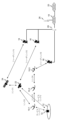
- Figure 2 shows an example of an NTN consisting of geostationary orbit satellites (GEO satellites), low earth orbit satellites (LEO satellites), and a HAPS network.
- GEO satellites geostationary orbit satellites
- LEO satellites low earth orbit satellites
- HAPS network a HAPS network
- the satellites 22, 24 and the aircraft 10 belonging to each network connect links with each other to form a network.
- the satellites 22, 24 and the aircraft 10 have a routing function, and the traffic transmitted from the UE 14 is transferred by them and sent to the Internet network.
- traffic generated between the UE 14 and the Internet will be routed to each satellite 22, 24 in the GEO or LEO satellite network or the aircraft 10 in the HAPS network as nodes. Ru.
- Each of these networks has different characteristics. Table 1 shows the characteristics of each network.
- the altitudes of the flying object 10 and the satellites 22 and 24 are different, and there is a large difference in signal propagation delay depending on which route they take.
- the GEO satellite 24 exists at an altitude of about 36,000 km, it takes at least about 120 ms for the signal transmitted from the UE 14 to arrive at the satellite 24, although it depends on the elevation angle.
- the aircraft 10 of the HAPS network exists at an altitude of about 20 km, the time it takes for the signal transmitted from the UE 14 to arrive at the aircraft 10 is about 0.07ms, which is longer than when the signal goes via the GEO satellite 24. Low delay.
- the bandwidth of the link between the nodes of the satellites 22, 24 and the aircraft 10 may also differ. There is sex.
- the following non-patent document 1 proposes a routing method that takes into consideration the propagation delay time due to the distance between the satellite/aircraft node, the bandwidth of the link between the satellite/aircraft node, and the like.
- the mobile communication system UE14 is used for a wide variety of applications, including voice calls, video transmission, and IoT communication using sensors.
- the required QoS Quality of Service
- the required transmission speed and allowable latency differ depending on the application. For example, voice calls require low latency, and video transmission requires a certain high transmission speed, although this depends on image quality and other factors.
- E2E End to End
- traffic can flow through various routes from the satellites 22, 24 or the aircraft 10 to which the UE 14 connects to the mobile network 18 on the ground. Since the propagation delay times and bands between nodes such as the satellites 22 and 24 and the flying object 10 differ, it is necessary to set a route suitable for the required QoS. Furthermore, if a transmission speed above a certain level is required as the required QoS, it is necessary to secure a band that satisfies the requirement in the link connecting the satellites 22, 24 and the aircraft 10 included in the set route.
- Non-Patent Document 1 does not take into account the QoS required by the application used by the UE 14. Furthermore, this technology performs routing control to select the optimal link for each link, and does not calculate a route overlooking E2E. Therefore, the technique described in Non-Patent Document 1 cannot necessarily satisfy the QoS required by E2E.
- the present disclosure has been made in view of the above-mentioned problems, and its primary purpose is to provide a wireless communication system that sets a route that satisfies the QoS required for each application used in a wireless terminal in a non-terrestrial network using E2E. 1 purpose.
- a second object of the present disclosure is to provide a communication path control device that sets a route that satisfies the QoS required for each application used in a wireless terminal in E2E in a non-terrestrial network.
- a third objective of the present disclosure is to provide a communication path control method for setting a route that satisfies the QoS required for each application used in a wireless terminal in E2E in a non-terrestrial network.
- a fourth objective of the present disclosure is to provide a communication path control program for setting a route that satisfies the QoS required for each application used in a wireless terminal in E2E in a non-terrestrial network.
- a first aspect configures a network in which a plurality of communication stations link to each other and transfer packets, and the plurality of communication stations perform connection communication that provides a service area to wireless terminals.
- a wireless communication system including a station, wherein the wireless terminal connects to the connecting communication station and transmits and receives packets to and from a data network, QoS collection processing for collecting requested QoS information corresponding to the service type of the wireless terminal; quality prediction processing for predicting communication quality in links between the plurality of communication stations; a route determination process that determines a communication route based on the communication quality so that the required QoS is satisfied between the connected communication station and the data network; distributing a routing table including traffic transfer destination information to at least communication stations included in the communication route; comprising a control station configured to perform It is preferable that a communication station included in the communication path is configured to transfer packets between the wireless terminal and the data network according to the routing table.
- a plurality of communication stations constitute a network in which a plurality of communication stations are linked to each other and transfer packets, and the plurality of communication stations include a connecting communication station that provides a service area to a wireless terminal, and the plurality of communication stations include a connecting communication station that provides a service area to a wireless terminal;
- a communication path control device that controls a communication path when a terminal connects to the connection communication station and transmits and receives packets to and from a data network, QoS collection processing for collecting requested QoS information corresponding to the service type of the wireless terminal; quality prediction processing for predicting communication quality in links between the plurality of communication stations; a route determination process that determines a communication route based on the communication quality so that the required QoS is satisfied between the connected communication station and the data network; distributing a routing table including traffic transfer destination information to at least communication stations included in the communication route; It is preferable that the system be configured to run .
- a plurality of communication stations constitute a network in which a plurality of communication stations are linked to each other and transfer packets, and the plurality of communication stations include a connecting communication station that provides a service area to a wireless terminal, and the plurality of communication stations include a connecting communication station that provides a service area to a wireless terminal, and
- a communication path control method for controlling a communication path when a terminal connects to the connecting communication station and transmits and receives packets to and from a data network comprising: a QoS collection step of collecting requested QoS information corresponding to the service type of the wireless terminal; a quality prediction step of predicting communication quality in links between the plurality of communication stations; a route determining step of determining a communication route based on the communication quality so that the required QoS is satisfied between the connected communication station and the data network; distributing a routing table containing traffic forwarding destination information to at least communication stations included in the communication route; a step in which a communication station included in the communication path transfers packet
- a plurality of communication stations constitute a network in which a plurality of communication stations link to each other and transfer packets, and the plurality of communication stations include a connecting communication station that provides a service area to a wireless terminal, and the plurality of communication stations include a connecting communication station that provides a service area to a wireless terminal, and A communication path control program for controlling a communication path when a terminal connects to the connecting communication station and transmits/receives packets to/from a data network, the program comprising: to the processor unit, QoS collection processing for collecting requested QoS information corresponding to the service type of the wireless terminal; quality prediction processing for predicting communication quality in links between the plurality of communication stations; a route determination process that determines a communication route based on the communication quality so that the required QoS is satisfied between the connected communication station and the data network; distributing a routing table including traffic transfer destination information to at least communication stations included in the communication route; It is desirable to include a program that executes.
- FIG. 2 is a diagram showing an example of an NTN configured from a HAPS network.
- FIG. 2 is a diagram showing an example of an NTN composed of a geostationary orbit satellite, a low orbit satellite, and a HAPS network.
- 1 is a diagram showing the configuration of a wireless communication system according to Embodiment 1 of the present disclosure.
- 4 is a flowchart for explaining the flow of processing executed in the wireless communication system shown in FIG. 3.
- FIG. FIG. 2 is a diagram for explaining an example of the operation of the wireless communication system according to Embodiment 1 of the present disclosure.
- 12 is a flowchart for explaining the operation of the wireless communication system according to Embodiment 3 of the present disclosure.
- FIG. 7 is a diagram for explaining an example of the operation of the wireless communication system according to Embodiment 6 of the present disclosure.
- FIG. 3 shows a wireless communication system according to Embodiment 1 of the present disclosure.
- the wireless communication system of this embodiment includes a GEO satellite 24, a LEO satellite 22, a flying object 10, a UE 14, a ground base station 16, a mobile core network 18, and a route control device 26.
- GEO satellite 24, LEO satellite 22, and flying vehicle 10 form a service area 12 with respect to the ground as part of a GEO satellite network, a LEO satellite network, and a HAPS network, respectively.
- the aircraft 10 is equipped with a base station function and can accommodate the UEs 14 within the service area 12 and connect them to the network. Further, the satellites 22 and 24 and the flying object 10 are equipped with a link function and a routing function for relaying signals. The satellites 22 , 24 and the aircraft 10 establish a network by establishing connection links between them, and relay transmission and reception signals between the UE 14 within the service area 12 and the mobile core network 18 .
- the UE 14 is compatible with a mobile communication system, connects to the data network 20 via the HAPS network configured by the aircraft 10, and executes various communication applications.
- the ground base station 16 transmits and receives signals between the satellites 22, 24 and the aircraft 10 and the mobile core network 18 on the ground.
- the mobile core network 18 performs management of the connected UE 14, mobility control such as handover, transmission/reception session control, etc. Mobile core network 18 further transfers packets between UE 14 and data network 20.
- the system of this embodiment includes a route control device 26 as part of the mobile core network 18.
- the route control device 26 derives the effective transmission rate etc. from information such as propagation delay time according to the distance of each link and the band used by each link. Then, based on the derived results, the route control device 26 selects a route between the mobile core network 18 and the satellites 22, 24 or the aircraft 10 to which the UE 14 is connected for each session. and distributes a routing table for route setting to the aircraft 10.
- the route control device 26 can be configured by combining dedicated hardware.
- the route control device 26 may be configured by hardware including a processor unit and a memory device.
- the desired function may be realized by storing a dedicated communication path control program in the memory device and having the processor unit execute the program.
- FIG. 4 is a flowchart for explaining the flow of processing executed in the system of this embodiment.
- the UE 14 connected to the network notifies the mobile core network 18 of the service type of the application to be used (step 100).
- the route control device 26 included in the mobile core network 18 selects a route to be used (step 102). Specifically, the connection between the satellites 22, 24 or the aircraft 10 to which the UE 14 is connected and the mobile core network 18 is based on the service type of the application, the link information between the satellites 22, 24, the aircraft 10, etc. A route is calculated or selected for the session between.
- the route control device 26 distributes a routing table to the satellites 22, 24 and the aircraft 10 so that the route selected by the above process is used (step 104).
- the mobile core network 18 sets up a session between the satellites 22, 24 or the aircraft 10 to which the UE 14 is connected and the mobile core network 18 (step 106).
- the mobile core network 18 issues transmission control commands to the satellites 22, 24 and the aircraft 10 included in the set session route in order to satisfy the required transmission speed required by the QoS.
- the transmission control command includes a command requesting the satellites 22, 24 and the flying object 10 to guarantee the bandwidth necessary to satisfy QoS.
- the satellites 22, 24 and the flying object 10 receive the above command, they perform transmission control such as transmission scheduling and priority transmission so that the band guarantee is satisfied.
- FIG. 5 shows an example of a network assumed to explain the operation of the system of this embodiment.
- the GEO satellite network and the LEO satellite network are each composed of one GEO satellite 24 and one LEO satellite 22.
- the HAPS network includes three aircraft 10. This network uses IP-based packet routing. It is assumed that IP addresses are assigned to the satellites 22, 24, the flying object 10, the router 28, and the like. Table 2 shows examples of IP addresses assigned to each element.
- each link there are four links between the satellites 22, 24 and the aircraft 10.
- the bandwidth and propagation delay of each link depend on the performance of the communication devices mounted on the satellites 22, 24 and the flying object 10, the distance of the link, etc., and can be specified based on known information.
- Table 3 shows an example of the bandwidth and propagation delay of each link.
- LEO satellite 22 moves relative to the flying object 10 constituting the HAPS and the GEO satellite 24. Therefore, a plurality of LEO satellites 22 in orbit are used for communication in a sequential manner. As a result, link 1 connecting GEO satellite 24 and LEO satellite 22, and link 2 connecting aircraft 10 and LEO satellite 22, were repeatedly disconnected and connected, resulting in frequent interruptions, and as shown in Table 3, Jitter occurs.
- the aircraft 10 and the satellites 22 and 24 are each equipped with one ground base station and are connected to the mobile core network 18.
- Table 4 shows the bands and propagation delays in the link (service link) between the UE 14 and the aircraft 10, and the link (feeder link) between the satellites 22, 24 and the aircraft 10 and the ground base station 16.
- the flying object 10 forms a service area 12 with a beam on the ground surface.
- the UE 14 within the service area 12 connects to the aircraft 10 and communicates with the data network 20 via various satellite networks, the HAPS network, and the mobile core network 18.
- Table 5 shows examples of service types that are assumed to be used by the UE 14 and the required QoS corresponding to each service type. In this embodiment, an example in which the UE 14 uses service type 2 will be described.
- the UE 14 belonging to the service area 12 provided by the first aircraft 10-1 connects to the aircraft 10-1 when starting communication. Thereafter, information on the UE 14 is transmitted to the mobile core network 18 via links 3 and 4, and after registration (attachment) processing and the like of the UE 14 are performed, a session is established between the UE 14 and the mobile core network 18. It will be done.
- the route control device 26 calculates a route suitable for each session. Specifically, first, the UE 14 notifies the mobile core network 18 of the service type. Next, the route control device 26 within the mobile core network that has received the notification of the service type calculates or selects a route that satisfies the required QoS for each service type for the session. For the UE 14 of service type 2, a route via service link ⁇ link 3 ⁇ link 4 ⁇ feeder link 3 is suitable as one that satisfies the required QoS.
- a route via service link ⁇ link 3 ⁇ link 4 ⁇ feeder link 3 is selected for the session. 1 is assigned as the ID of this session, and the routing table is distributed to the satellites 22, 24 and the aircraft 10 on the route.
- Table 6 shows an example of a routing table when traffic flows from the UE 14 to the mobile core network 18.
- the UE 14 After the table distribution described above is completed, the UE 14 starts communication.
- the traffic flowing from the UE 14 to the mobile core network 18 includes the IP address and session ID of the destination mobile core network 18. Additionally, each of the aircraft 10, satellites 22, 24, and router 28 refers to the session ID in addition to the destination IP address to direct traffic to the next hop. This makes it possible to forward traffic along a route specified for each session.
- a routing table for a reverse route with the aircraft 10-1 as the destination is distributed. This makes it possible to forward traffic along a route specified for each session.
- the satellites 22, 24 and the flying object 10 on the route issue commands to perform transmission control and band control to satisfy the required transmission speed for each session.
- the route (hereinafter referred to as “aircraft route") is selected.
- the aircraft 10-1, 10-2, and 10-3 existing on the route schedule the transmission of packets with the session ID added so as to meet the required transmission speed of 30 Mbit/s.
- Performs transmission control such as priority transmission and priority transmission.
- the UE 14 starts communication.
- the wireless communication system of this embodiment selects an appropriate route according to the QoS requested by the UE 14, taking into account the bandwidth, propagation delay, and jitter of each link. Therefore, according to the system of this embodiment, it is possible to appropriately satisfy the QoS request of the UE 14 while utilizing NTN.
- the UE 14 is of service type 2, but for the UE 14 of service type 1, the following two routes can be used. Since both of these routes satisfy the QoS requirement of the UE 14, one of the routes will be selected for the session. 1.
- the above “aircraft route” passes through aircraft 10-1 to 10-3. 2.
- a route using link 2 and feeder link 2 via LEO satellite 22 (hereinafter referred to as "LEO route").
- the following third route can be used. 3.
- GEO route A route using link 2, link 1, and feeder link 1 via GEO satellite 24 (hereinafter referred to as "GEO route"). Therefore, if the UE 14 uses service type 3, it will select any of the routes 1 to 3 above for the session.
- a route for a session is calculated or selected based on the bandwidth, propagation delay, and jitter of the link between the satellites 22, 24 and the flying object 10, but the present disclosure is not limited to this. It's not a thing.
- route selection may be performed by taking into account the time required for relay processing in the aircraft 10 and the satellites 22 and 24.
- route selection may be performed using measures such as the error rate and packet loss rate of each link.
- the present embodiment shows an example in which the base station function is mounted on the flying object 10, the present disclosure is not limited thereto.
- the satellites 22 and 24 are equipped with a base station function and the UE 14 is connected to the satellites 22 and 24, the same processing as in this embodiment is possible.
- the location where the base station function is installed is not limited to the satellites 22, 24 or the aircraft 10.
- the technology according to the present disclosure can also be applied, for example, when a base station function is installed on the ground and a satellite network or HAPS network is used as a backhaul line.
- a base station function is installed on the ground and a satellite network or HAPS network is used as a backhaul line.
- the satellites 22, 24 or the flying object 10 are equipped with a link function or a routing function for relaying signals, the same processing as in this embodiment is possible.
- the performance of communication routes determined in the past may be stored in a database, and when selecting a communication route for a newly connected wireless terminal, the communication route may be calculated with reference to the above database.
- the communication routes assigned to the requested QoS similar to the requested QoS of the new wireless terminal may be read from the database, and candidate routes may be narrowed down. According to such a method, the time for route selection can be shortened.
- the basis for route selection we focus on the transmission speed of each link, available bandwidth, propagation delay time, frequency of disconnection, etc.
- these are examples of information that can be used as a basis for route selection, and the present disclosure is not limited thereto.
- the connection time allowed for each link (link connection time), the stability of each link, etc. may be used as the basis for route selection.
- Embodiment 2 The wireless communication system of this embodiment can be realized by the configuration shown in FIG. 3 or FIG. 5, as in the case of the first embodiment described above.
- the system of the first embodiment selects a communication route based on link bandwidth and propagation delay.
- the wireless communication system of this embodiment is characterized in that route selection is based on the number of sessions in which each link is used, the amount of traffic flowing through each link, and the like. More specifically, the system of this embodiment is characterized in that it calculates the surplus bandwidth and effective transmission speed for each link based on the number of sessions and traffic volume described above, and reflects the results in route selection. are doing.
- Table 8 below shows examples of the number of sessions accommodated by each route by service type. Note that the "-" entered in the "Service Type 1" and “Service Type 2" columns at the top of Table 8 indicates that the route via GEO satellite 24 accepts those service types that require high capacity and low delay. It means that there is no. The second row of Table 8 similarly indicates that the route via LEO satellite 22 does not accept “service type 2.”
- Each link is given a usable band in advance.
- the surplus bandwidth of the link accommodating sessions decreases as the number of sessions accommodating increases.
- Table 9 illustrates the used bandwidth of each link shown in FIG. 5 and the surplus bandwidth when the links accommodate the number of sessions shown in Table 8 above.
- the GEO route, LEO route, and aircraft route are all appropriate from the perspective of propagation delay.
- link 1 included in the GEO route has zero surplus bandwidth in Table 9.
- the GEO route also has an effective transmission rate of zero, it is determined that the GEO route is unsuitable as a route for the new UE 14.
- the route control device 26 of this embodiment selects either the LEO route using link 2 and feeder link 2, or the aircraft route using link 3, link 4, and feeder link 3.
- the surplus bandwidth of each link is calculated from the number of sessions accommodated in each route, but the present disclosure is not limited to this.
- the amount of traffic flowing through each route may be detected, and the surplus bandwidth or effective transmission rate of each link may be calculated from the amount of traffic.
- Embodiment 3 Next, a wireless communication system according to a third embodiment of the present disclosure will be described with reference to FIG. 6 together with FIGS. 3 and 5.
- the wireless communication system of this embodiment can be realized by the configuration shown in FIG. 3 or FIG. 5, as in the case of the first embodiment described above.
- the mobile core network 18 is a 5G compatible mobile core network (5GC).
- 5GC used in this embodiment will be described with reference numeral 18 as in the first and second embodiments.
- a GPRS (General Packet Radio Service) tunnel is set up between a 5G base station (gNB: next Generation Node B) and 5GC18 using GTP (GPRS Tunneling Protocol).
- gNB next Generation Node B
- GTP GPRS Tunneling Protocol
- the aircraft 10 is equipped with a gNB function as a base station function, and a GPRS tunnel is formed between the aircraft 10 and the 5GC.
- FIG. 6 shows a flowchart of operations performed in the wireless communication system of this embodiment.
- the UE 14 when connecting to the 5GC 18, the UE 14 transmits Requested NSSAI (Network Slicing Selection Assistance information) including service type information to the gNB mounted on the flight object 10.
- gNB transmits the received information to AMF (Access and Mobility Management Function) in 5GC 18 (step 110).
- AMF Access and Mobility Management Function
- the AMF sets SMF (Session Management Function) and UPF (User Plane Function) according to the service type (step 112).
- the route control device 26 of the 5GC 18 calculates and selects a route for the GPRS tunnel between the satellites 22, 24 or the flying object 10 to which the UE 14 is connected and the UFP included in the 5GC 18 (step 114).
- the route selection is performed based on the link information between the satellites 22, 24 and the flying object 10, etc., as in the first or second embodiment.
- the route control device 26 then distributes the routing table to the satellites 22, 24 and the aircraft 10 so that the route selected in the above process is used (step 116).
- This process is substantially the same as the process in step 104 described above in the first embodiment (see Tables 6 and 7).
- the 5GC 18 sets up a GPRS tunnel between the satellites 22, 24 and the flying object 10 to which the UE 14 is connected and the 5GC 18 (step 118).
- the UE 14 located within the service area 12 of the aircraft 10-1 connects to the aircraft 10-1 when starting communication.
- connection is made to the 5GC 18 via link 3 ⁇ link 4 ⁇ feeder link 3, which is set as the default route for control signals.
- registration (attachment) processing of the UE 14 and the like are performed.
- the UE 14 transmits the Requested NSSAI including service type information to the 5GC 18.
- SMF and UPF are set for each service type information.
- a GPRS tunnel is formed between the configured UFP and the gNB function provided in the aircraft 10-1 to 10-3.
- the route control device 26 of the 5GC 18 calculates or selects a route that satisfies the requested QoS for each service type based on the service type included in the Requested NSSAI for the GPRS tunnel between the gNB and the UPF.
- the QoS required by service type 2 can be satisfied by a route via link 3, link 4, and feeder link 3. Therefore, in this operational example, this route is selected for the GPRS tunnel for the UE 14.
- the route control device 26 assigns a unique TEID (Tunnel Endpoint Identifier) to each GPRS tunnel, and distributes a routing table to the satellites 22, 24 and the aircraft 10 on the route.
- Table 10 shows an example of a routing table when traffic flows from the UE 14 to the 5GC 18.
- 1 is assigned to TEID.
- the satellites 22, 24 and the flying object 10 on the route issue commands for transmission control and band control to satisfy the required transmission speed for each session. Then, when a GPRS tunnel is established between the gNB and the UPF, the UE 14 starts communication.
- the traffic flowing from the UE 14 to the 5GC 18 includes the TEID in addition to the destination IP address.
- the aircraft 10, satellites 22, 24, and routers on the route refer to the TEID in addition to the destination IP address to direct traffic to the next hop. This makes it possible to forward traffic using a route specified for each GPRS tunnel.
- a routing table for the reverse route is distributed. This makes it possible to forward traffic using a route specified for each GPRS tunnel.
- the wireless communication system of this embodiment selects a route suitable for the GPRS tunnel according to the QoS requested by the UE 14, taking into account the bandwidth, propagation delay, and jitter of each link. Therefore, according to the system of this embodiment, the QoS required by the UE 14 can be appropriately satisfied while utilizing NTN and complying with the 5G communication standard.
- service type information is conveyed to the 5GC 18 using NSSAI.
- the service type information may be notified using, for example, 5QI (5G QoS Identifier) or ARP (Address Resolution Protocol).
- Embodiment 4 Next, a fourth embodiment of the present disclosure will be described.
- the wireless communication system of this embodiment can be realized by the configuration shown in FIG. 3 or FIG. 5, as in the first to third embodiments described above.
- a communication route is selected every time the UE 14 communicates.
- the link bandwidth between the satellites 22, 24 and the aircraft 10 is limited, if sessions or tunnels continue to be accommodated, the transmission speed that satisfies the QoS will not be able to be achieved. As a result, a situation arises in which the link between the satellites 22, 24 and the vehicle 10 cannot accommodate sessions or tunnels.
- the aircraft route is suitable as a route that satisfies QoS.
- the above LEO route can satisfy QoS as well as the aircraft route. Therefore, for the UE 14 of service type 1, both the aircraft route and the LEO route are candidates for the adopted route.
- QoS can be satisfied by the GEO route as well as by the aircraft route and the LEO route. Therefore, in this case, there are three candidate routes.
- the wireless communication system of this embodiment is characterized in that the route control device 26 sets a policy for changing the route to be preferentially selected for each service type. Specifically, in this embodiment, the following policies are set.
- Service type 2 Select aircraft route preferentially
- Service type 3 Prioritize GEO route selection
- Embodiment 5 Next, Embodiment 5 of the present disclosure will be described.
- the wireless communication system of this embodiment can be realized by the configuration shown in FIG. 3 or FIG. 5, as in the first to fourth embodiments described above.
- priorities may be set for each service type.
- the wireless communication system of this embodiment is characterized in that the number of sessions accommodated and the allocated bandwidth are set in advance for each service type, depending on the priority, for the link between the satellites 22, 24 and the aircraft 10. have.
- this embodiment it is possible to reserve a session or tunnel band for the UE 14 of a high priority service type. Then, when the number of communications of a service type with a low priority increases, that type of communication is restricted. Therefore, according to the system of this embodiment, it is possible to always accommodate a certain number of communications of high priority service types.
- the system of this embodiment further has a function of changing the settings of allocated bandwidth and number of accommodated sessions for each service type in accordance with changes in network conditions. For example, in the event of a severe disaster, it will be necessary to prioritize communication via smartphones over IoT communications. In other words, it will be necessary to lower the priority of IoT communication and raise the priority of smartphone communication.
- the system of this embodiment reduces the proportion of the allocated bandwidth and the number of sessions accommodated for service type 3 (the majority IoT service). As a result, the proportion of bandwidth and number of accommodated sessions allocated to service type 1, that is, high-speed, large-capacity services for smartphone communication, increases. Therefore, according to the system of this embodiment, when a severe disaster occurs, it is possible to accommodate more communications by smartphones than in normal times.
- information such as the number of accommodated sessions according to the priority can be stored in a memory device included in the route control device 26, for example.
- the route control device 26 may acquire the above information from an externally installed memory device.
- Embodiment 6 Next, a sixth embodiment of the present disclosure will be described with reference to FIG. 7 together with FIGS. 3 and 5.
- the wireless communication system of this embodiment can be realized by the configuration shown in FIG. 3 or FIG. 5, as in the first to fifth embodiments described above.
- the UE 14 has a function of connecting to a plurality of relay points including the LEO satellites 22 and 24 and the flying object 10.
- Embodiment 1 of the present disclosure it is assumed that the UE 14 connects to a single aircraft 10, and a session route is selected between the aircraft 10 and the mobile core network 18.
- the UE 14 can connect to a plurality of relay points including the satellites 22, 24 and the aircraft 10 as described above, there are multiple candidates between the UE 14 and the satellites 22, 24 and the aircraft 10. Root occurs.
- FIG. 7 illustrates a configuration in which the UE 14 can connect to both the HAPS and LEO satellite networks.
- candidate routes for connecting the UE 14 and the NTN there are a service link 1 having the flying object 10-1 as a relay point and a service link 2 having the LEO satellite 22 as a relay point.
- candidate routes using service link 2 include two routes: a route via feeder link 2 and a route via link 1 and feeder link 1.
- the route control device 26 selects one of the three routes described above for the service type 1 session.
- the UE 14 uses service type 2, that is, ultra-reliable low-delay service, the only route that satisfies the required QoS is the aircraft route. Therefore, in this case, a route via service link 1, link 3, link 4 and feeder link 3 is selected for the session.
- service type 2 that is, ultra-reliable low-delay service
- handover control is performed for service links 1 and 2.
- the connection to a given flight vehicle 10 or LEO satellite 22 is maintained or switched.
- the route from the aircraft 10 and the satellites 22 and 24 to the mobile core network 18 can be appropriately set for the session using the same process as in the first embodiment.
- Embodiment 7 Next, a seventh embodiment of the present disclosure will be described.
- the wireless communication system of this embodiment can be realized by the configuration shown in FIG. 3 or FIG. 5, as in the first to sixth embodiments described above.
- the communication quality between the satellites 22, 24 and the aircraft 10 varies depending on the movement of the LEO satellite 22 and the aircraft 10.
- the LEO satellite 22 is moving relative to the HAPS vehicle 10 and the GEO satellite 24. Therefore, the distance of the link between the flying object 10 and the LEO satellite 22 and the distance of the link between the LEO satellite 22 and the GEO satellite 24 change over time. As a result, the propagation delay times in those links also vary over time.
- the reception gains in the satellites 22, 24 and the flying object 10 also change depending on time. Further, the angle between the flying object 10 or the GEO satellite 24 and the LEO satellite 22 also changes, and this change causes a change in the receiving gain of the antenna mounted on them. Therefore, when an adaptive modulation and coding scheme is used to change the modulation and demodulation scheme and coding rate in conjunction with the reception gain, the effective transmission speed also changes in response to changes in the reception gain.
- the orbit of LEO satellite 22 is known in advance. Therefore, if the current positions of the LEO satellites 22 and the aircraft 10 are known, the future distances and angles between the LEO satellites 22 and the GEO satellites 24, as well as the future distances and angles between the LEO satellites 22 and the aircraft 10, can be calculated. It can be predicted by
- the wireless communication system of this embodiment predicts the distances of each link connecting the satellites 22, 24 and the flying object 10, as well as their angles, and then performs the following processing. Note that these processes are performed by the route control device 26. However, these processes may be executed in a device different from the route control device 26.
- step 3 Based on the results of 1 and 2 above, for each candidate route, calculate the longest propagation delay time and lowest effective transmission rate among the links included therein. The longest propagation delay time and lowest effective transmission rate obtained as a result are taken as the propagation delay time and effective transmission rate of each candidate route. 4. Using the results of step 3 above, a route that satisfies the QoS requested by the UE 14 is calculated or selected.
- the distance and angle of the link can be estimated using the same method as described above, and the results can be reflected in route selection.
- the fluctuation situation is predicted in real time and the result is reflected in route selection, but the present disclosure is not limited to this.
- a training period may be provided before starting the operation of the system, and fluctuations in communication quality may be observed in advance and stored in the memory device.
- the communication route may be determined using the information on the fluctuation status stored in the memory device.
- the wireless terminal when a wireless terminal communicates, it becomes possible to set an end-to-end route that satisfies the required QoS. Therefore, it becomes possible to cause the wireless terminal to execute various applications. Also, in the 5th generation mobile system, it becomes possible to appropriately set the route of the GPRS tunnel established between the wireless base station and the 5G core network so as to satisfy the QoS required by the wireless terminal.
- the wireless communication system uses NTN, but the present disclosure is not limited to this. That is, the communication route setting method according to the present disclosure can be widely applied when a network including a plurality of links with different bands and propagation delays is used.
- Wireless terminal 16
- Ground base station 18
- Mobile core network 5GC
- Data network 22
- LEO satellite 24
- GEO satellite 26
- Route control device 28 Router
Landscapes
- Engineering & Computer Science (AREA)
- Computer Networks & Wireless Communication (AREA)
- Signal Processing (AREA)
- Physics & Mathematics (AREA)
- Astronomy & Astrophysics (AREA)
- General Physics & Mathematics (AREA)
- Mobile Radio Communication Systems (AREA)
Abstract
The present disclosure relates to a wireless communication system. The purpose of the present disclosure is to set a route that, with E2E, satisfies the QoS required per application used in a wireless terminal in a non-terrestrial network. A plurality of communication stations such as an aircraft 10, LEO satellite 22, and GEO satellite 24 establish links between each other and transmit packets. A UE 14 connects to an aircraft 10-1 that provides a service area and sends/receives packets to/from a data network 18. A route control device 18 collects information pertaining to required QoS that corresponds to the service type of the UE 14; predicts the communication quality of a link between communication stations; and determines a communication route on the basis of the communication quality so that the required QoS is satisfied between the aircraft 10-1 and the data network 18. A communication station included in the communication route receives distribution of a routing table that includes the traffic transmission destination information and transmits packets in accordance with the information.
Description
この開示は、無線通信システム、通信経路制御装置、通信経路制御方法および通信経路制御用プログラムに係り、特に、非地上ネットワークを活用した効率的な無線通信を可能とするうえで好適な無線通信システム、通信経路制御装置、通信経路制御方法および通信経路制御用プログラムに関する。
This disclosure relates to a wireless communication system, a communication route control device, a communication route control method, and a communication route control program, and in particular, a wireless communication system suitable for enabling efficient wireless communication using a non-terrestrial network. , relates to a communication route control device, a communication route control method, and a communication route control program.
近年、モバイル通信システムが発展し、地上の大部分において、モバイルサービスを享受することができる。今後商用化が期待される第5世代あるいは第6世代モバイル通信システムにおける要求条件の一つとして、超カバレッジ化がある。超カバレッジ化とは、山岳地、海上、空中のように既存の基地局の敷設コストが高価となるエリア、あるいは基地局の敷設が困難なエリアにサービスを拡大することである。また、自然災害などに対する国土強靭化も必要とされており、地上災害に強い通信システムの登場が望まれている。
In recent years, mobile communication systems have developed and it is now possible to enjoy mobile services in most parts of the earth. One of the requirements for 5th or 6th generation mobile communication systems, which are expected to be commercialized in the future, is ultra-coverage. Super-coverage refers to expanding services to areas where it is expensive to install existing base stations, such as mountainous areas, the sea, and the air, or areas where it is difficult to install base stations. There is also a need to strengthen national resilience against natural disasters, and it is hoped that a communication system that can withstand ground disasters will emerge.
上記の要求に応えるために、衛星や無人飛行体(UAV)、高高度擬似衛星(HAPS)、ドローンなどを用いた非地上ネットワーク(Non Terrestrial Network : NTN)が脚光を浴びている。HAPSネットワークから構成されるNTNの例を図1に示す。
In order to meet the above requirements, non-terrestrial networks (NTN) using satellites, unmanned aerial vehicles (UAVs), high-altitude pseudo-satellites (HAPS), drones, etc. are in the spotlight. Figure 1 shows an example of an NTN consisting of a HAPS network.
無人飛行体(以下、飛行体)10は地上に対してビームを照射してモバイルサービスエリアを形成する機能を有している。サービスエリア12の中に存在する地上の無線端末(以下、UE:User Equipment)14はHAPSの飛行体10に接続し、飛行体10を経由して地上基地局16に接続する。飛行体10には信号中継機能が搭載されている。UE14から送信されたパケットは、飛行体10や地上基地局16、モバイルネットワーク18を介してデータネットワーク20に送られる。データネットワーク20からUE14に宛てたパケットも同様に中継される。
An unmanned flying vehicle (hereinafter referred to as a flying vehicle) 10 has a function of irradiating a beam onto the ground to form a mobile service area. A ground wireless terminal (hereinafter referred to as UE: User Equipment) 14 existing within the service area 12 connects to the HAPS aircraft 10 and connects to the ground base station 16 via the aircraft 10. The aircraft 10 is equipped with a signal relay function. Packets transmitted from the UE 14 are sent to the data network 20 via the aircraft 10, the ground base station 16, and the mobile network 18. Packets destined for the UE 14 from the data network 20 are also relayed in the same way.
将来的には、複数の衛星及びHAPSネットワークから構成される多層衛星ネットワークが考えられる。静止軌道衛星(GEO衛星)、低軌道衛星(LEO衛星)、HAPS ネットワークから構成されるNTNの例を図2に示す。
In the future, a multi-layer satellite network consisting of multiple satellites and a HAPS network is conceivable. Figure 2 shows an example of an NTN consisting of geostationary orbit satellites (GEO satellites), low earth orbit satellites (LEO satellites), and a HAPS network.
図2に示すNTNでは、それぞれのネットワークに属する衛星22、24や飛行体10が互いにリンクを接続してネットワークを構成する。衛星22、24や飛行体10はルーティング機能を有しており、UE14から送信されたトラヒックは、それらにより転送されてインターネット網に送られる。
In the NTN shown in FIG. 2, the satellites 22, 24 and the aircraft 10 belonging to each network connect links with each other to form a network. The satellites 22, 24 and the aircraft 10 have a routing function, and the traffic transmitted from the UE 14 is transferred by them and sent to the Internet network.
図2に示す将来的な多層衛星ネットワークにおいては、UE14とインターネット間で生成されたトラヒックは、GEO衛星或いはLEO衛星ネットワーク内の各衛星22、24やHAPSネットワーク内の飛行体10をノードとしてルーティングされる。これらのネットワークは、それぞれ異なる特徴を有している。個々のネットワークに関する特徴を表1に示す。
In the future multi-layer satellite network shown in FIG. 2, traffic generated between the UE 14 and the Internet will be routed to each satellite 22, 24 in the GEO or LEO satellite network or the aircraft 10 in the HAPS network as nodes. Ru. Each of these networks has different characteristics. Table 1 shows the characteristics of each network.

表1に示すように、飛行体10や衛星22、24の高度はそれぞれ異なっており、何れのルートを経由するかに応じて信号の伝搬遅延には大きな差異が生ずる。GEO衛星24は高度約36,000kmに存在するため、UE14から送信した信号が衛星24に到着するまでには、仰角にもよるが、少なくとも約120msの時間を要する。一方、HAPSネットワークの飛行体10は高度約20kmに存在するため、UE14から送信した信号が飛行体10に到着するまでの時間は0.07msほどであり、GEO衛星24を経由する場合に比して低遅延となる。
As shown in Table 1, the altitudes of the flying object 10 and the satellites 22 and 24 are different, and there is a large difference in signal propagation delay depending on which route they take. Since the GEO satellite 24 exists at an altitude of about 36,000 km, it takes at least about 120 ms for the signal transmitted from the UE 14 to arrive at the satellite 24, although it depends on the elevation angle. On the other hand, since the aircraft 10 of the HAPS network exists at an altitude of about 20 km, the time it takes for the signal transmitted from the UE 14 to arrive at the aircraft 10 is about 0.07ms, which is longer than when the signal goes via the GEO satellite 24. Low delay.
また、衛星22、24や飛行体10に搭載される通信装置は、積載重量や消費電力などの制約に応じて異なることから、衛星22、24や飛行体10のノード間リンクの帯域も異なる可能性がある。これらに鑑みて、下記の非特許文献1には、衛星/飛行体ノード間距離による伝搬遅延時間や、衛星/飛行体ノード間リンクの帯域などを考慮したルーティングの手法が提案されている。
Furthermore, since the communication devices installed on the satellites 22, 24 and the aircraft 10 differ depending on constraints such as payload weight and power consumption, the bandwidth of the link between the nodes of the satellites 22, 24 and the aircraft 10 may also differ. There is sex. In view of these, the following non-patent document 1 proposes a routing method that takes into consideration the propagation delay time due to the distance between the satellite/aircraft node, the bandwidth of the link between the satellite/aircraft node, and the like.
一方、モバイル通信システムのUE14では、音声通話、動画伝送、センサを用いたIoT通信など、多種多様な用途のアプリケーションが用いられている。そして、アプリケーション毎に、要求される伝送速度や許容されるレイテンシなど、要求QoS(Quality of Service)は異なる。例えば、音声通話は低レイテンシが求められ、動画伝送においては、画質等によるが、ある一定の高い伝送速度が要求される。
On the other hand, the mobile communication system UE14 is used for a wide variety of applications, including voice calls, video transmission, and IoT communication using sensors. The required QoS (Quality of Service), such as the required transmission speed and allowable latency, differ depending on the application. For example, voice calls require low latency, and video transmission requires a certain high transmission speed, although this depends on image quality and other factors.
UE14において、上記のような様々なアプリケーションにおける要求QoSを満たすためには、UE14からデータネットワークまでのEnd to End(E2E)で、要求される伝送速度や遅延時間などを満たす制御が必要になる。
In order for the UE 14 to satisfy the QoS requirements of the various applications mentioned above, control is required to satisfy the required transmission speed, delay time, etc. End to End (E2E) from the UE 14 to the data network.
複数の衛星ネットワークから構成される多層衛星ネットワークにおいては、UE14が接続する衛星22、24や飛行体10から地上のモバイルネットワーク18までの間は様々なルートでトラヒックが流れ得る。そして、衛星22、24や飛行体10などのノード間のリンクにおける伝搬遅延時間や帯域が異なるため、要求QoSに適したルートの設定が必要になる。また、要求QoSとして一定以上の伝送速度が必要な場合は、設定したルートに含まれる衛星22、24や飛行体10を結ぶリンクにおいて要求を満たす帯域を確保することが必要になる。
In a multi-layer satellite network composed of multiple satellite networks, traffic can flow through various routes from the satellites 22, 24 or the aircraft 10 to which the UE 14 connects to the mobile network 18 on the ground. Since the propagation delay times and bands between nodes such as the satellites 22 and 24 and the flying object 10 differ, it is necessary to set a route suitable for the required QoS. Furthermore, if a transmission speed above a certain level is required as the required QoS, it is necessary to secure a band that satisfies the requirement in the link connecting the satellites 22, 24 and the aircraft 10 included in the set route.
上述の非特許文献1のルーティング技術では、UE14が用いるアプリケーションの要求QoSが考慮されていない。また、この技術では、リンク毎に最適なリンクを選択するルーティング制御が行われており、E2Eを見渡したルートの算出は行われていない。このため、非特許文献1に記載の技術では、E2Eで要求されるQoSを必ずしも満たすことができない。
The routing technology of Non-Patent Document 1 described above does not take into account the QoS required by the application used by the UE 14. Furthermore, this technology performs routing control to select the optimal link for each link, and does not calculate a route overlooking E2E. Therefore, the technique described in Non-Patent Document 1 cannot necessarily satisfy the QoS required by E2E.
本開示は、上記の課題に鑑みてなされたものであり、非地上ネットワークにおいて、無線端末で用いられるアプリケーション毎に要求されるQoSをE2Eで満たすルートを設定する無線通信システムを提供することを第1の目的とする。
The present disclosure has been made in view of the above-mentioned problems, and its primary purpose is to provide a wireless communication system that sets a route that satisfies the QoS required for each application used in a wireless terminal in a non-terrestrial network using E2E. 1 purpose.
また、本開示は、非地上ネットワークにおいて、無線端末で用いられるアプリケーション毎に要求されるQoSをE2Eで満たすルートを設定する通信経路制御装置を提供することを第2の目的とする。
A second object of the present disclosure is to provide a communication path control device that sets a route that satisfies the QoS required for each application used in a wireless terminal in E2E in a non-terrestrial network.
また、本開示は、非地上ネットワークにおいて、無線端末で用いられるアプリケーション毎に要求されるQoSをE2Eで満たすルートを設定するための通信経路制御方法を提供することを第3の目的とする。
A third objective of the present disclosure is to provide a communication path control method for setting a route that satisfies the QoS required for each application used in a wireless terminal in E2E in a non-terrestrial network.
また、本開示は、非地上ネットワークにおいて、無線端末で用いられるアプリケーション毎に要求されるQoSをE2Eで満たすルートを設定するための通信経路制御用プログラムを提供することを第4の目的とする。
A fourth objective of the present disclosure is to provide a communication path control program for setting a route that satisfies the QoS required for each application used in a wireless terminal in E2E in a non-terrestrial network.
第1の態様は、上記の目的を達成するため、複数の通信局が互いにリンクを張ってパケットを転送するネットワークを構成し、前記複数の通信局は、無線端末にサービスエリアを提供する接続通信局を含み、前記無線端末は、前記接続通信局に接続してデータネットワークとの間でパケットを送受信する無線通信システムであって、
前記無線端末のサービスタイプに対応する要求QoSの情報を収集するQoS収集処理と、
前記複数の通信局の間のリンクにおける通信品質を予測する品質予測処理と、
前記接続通信局と前記データネットワークとの間で前記要求QoSが満たされるように、前記通信品質に基づいて通信経路を決定する経路決定処理と、
少なくとも前記通信経路に含まれる通信局に、トラヒックの転送先情報を含むルーティングテーブルを配布する処理と、
を実行するように構成された制御局を備え、
前記通信経路に含まれる通信局は、前記ルーティングテーブルに従って、前記無線端末と前記データネットワークとの間でパケットを転送するように構成されていることが望ましい。 In order to achieve the above object, a first aspect configures a network in which a plurality of communication stations link to each other and transfer packets, and the plurality of communication stations perform connection communication that provides a service area to wireless terminals. A wireless communication system including a station, wherein the wireless terminal connects to the connecting communication station and transmits and receives packets to and from a data network,
QoS collection processing for collecting requested QoS information corresponding to the service type of the wireless terminal;
quality prediction processing for predicting communication quality in links between the plurality of communication stations;
a route determination process that determines a communication route based on the communication quality so that the required QoS is satisfied between the connected communication station and the data network;
distributing a routing table including traffic transfer destination information to at least communication stations included in the communication route;
comprising a control station configured to perform
It is preferable that a communication station included in the communication path is configured to transfer packets between the wireless terminal and the data network according to the routing table.
また、第2の態様は、複数の通信局が互いにリンクを張ってパケットを転送するネットワークを構成し、前記複数の通信局は、無線端末にサービスエリアを提供する接続通信局を含み、前記無線端末が、前記接続通信局に接続してデータネットワークとの間でパケットを送受信する際の通信経路を制御する通信経路制御装置であって、
前記無線端末のサービスタイプに対応する要求QoSの情報を収集するQoS収集処理と、
前記複数の通信局の間のリンクにおける通信品質を予測する品質予測処理と、
前記接続通信局と前記データネットワークとの間で前記要求QoSが満たされるように、前記通信品質に基づいて通信経路を決定する経路決定処理と、
少なくとも前記通信経路に含まれる通信局に、トラヒックの転送先情報を含むルーティングテーブルを配布する処理と、
を実行するように構成されていることが望ましい。 Further, in a second aspect, a plurality of communication stations constitute a network in which a plurality of communication stations are linked to each other and transfer packets, and the plurality of communication stations include a connecting communication station that provides a service area to a wireless terminal, and the plurality of communication stations include a connecting communication station that provides a service area to a wireless terminal; A communication path control device that controls a communication path when a terminal connects to the connection communication station and transmits and receives packets to and from a data network,
QoS collection processing for collecting requested QoS information corresponding to the service type of the wireless terminal;
quality prediction processing for predicting communication quality in links between the plurality of communication stations;
a route determination process that determines a communication route based on the communication quality so that the required QoS is satisfied between the connected communication station and the data network;
distributing a routing table including traffic transfer destination information to at least communication stations included in the communication route;
It is preferable that the system be configured to run .
また、第3の態様は、複数の通信局が互いにリンクを張ってパケットを転送するネットワークを構成し、前記複数の通信局は、無線端末にサービスエリアを提供する接続通信局を含み、前記無線端末が、前記接続通信局に接続してデータネットワークとの間でパケットを送受信する際の通信経路を制御するための通信経路制御方法であって、
前記無線端末のサービスタイプに対応する要求QoSの情報を収集するQoS収集工程と、
前記複数の通信局の間のリンクにおける通信品質を予測する品質予測工程と、
前記接続通信局と前記データネットワークとの間で前記要求QoSが満たされるように、前記通信品質に基づいて通信経路を決定する経路決定工程と、
少なくとも前記通信経路に含まれる通信局に、トラヒックの転送先情報を含むルーティングテーブルを配布する工程と、
前記通信経路に含まれる通信局が、前記ルーティングテーブルに従って、前記無線端末と前記データネットワークとの間でパケットを転送する工程と、
を含むことが望ましい。 Further, in a third aspect, a plurality of communication stations constitute a network in which a plurality of communication stations are linked to each other and transfer packets, and the plurality of communication stations include a connecting communication station that provides a service area to a wireless terminal, and the plurality of communication stations include a connecting communication station that provides a service area to a wireless terminal, and A communication path control method for controlling a communication path when a terminal connects to the connecting communication station and transmits and receives packets to and from a data network, the method comprising:
a QoS collection step of collecting requested QoS information corresponding to the service type of the wireless terminal;
a quality prediction step of predicting communication quality in links between the plurality of communication stations;
a route determining step of determining a communication route based on the communication quality so that the required QoS is satisfied between the connected communication station and the data network;
distributing a routing table containing traffic forwarding destination information to at least communication stations included in the communication route;
a step in which a communication station included in the communication path transfers packets between the wireless terminal and the data network according to the routing table;
It is desirable to include.
また、第4の態様は、複数の通信局が互いにリンクを張ってパケットを転送するネットワークを構成し、前記複数の通信局は、無線端末にサービスエリアを提供する接続通信局を含み、前記無線端末が、前記接続通信局に接続してデータネットワークとの間でパケットを送受信する際の通信経路を制御するための通信経路制御用プログラムであって、
プロセッサユニットに、
前記無線端末のサービスタイプに対応する要求QoSの情報を収集するQoS収集処理と、
前記複数の通信局の間のリンクにおける通信品質を予測する品質予測処理と、
前記接続通信局と前記データネットワークとの間で前記要求QoSが満たされるように、前記通信品質に基づいて通信経路を決定する経路決定処理と、
少なくとも前記通信経路に含まれる通信局に、トラヒックの転送先情報を含むルーティングテーブルを配布する処理と、
を実行させるプログラムを含むことが望ましい。 Further, in a fourth aspect, a plurality of communication stations constitute a network in which a plurality of communication stations link to each other and transfer packets, and the plurality of communication stations include a connecting communication station that provides a service area to a wireless terminal, and the plurality of communication stations include a connecting communication station that provides a service area to a wireless terminal, and A communication path control program for controlling a communication path when a terminal connects to the connecting communication station and transmits/receives packets to/from a data network, the program comprising:
to the processor unit,
QoS collection processing for collecting requested QoS information corresponding to the service type of the wireless terminal;
quality prediction processing for predicting communication quality in links between the plurality of communication stations;
a route determination process that determines a communication route based on the communication quality so that the required QoS is satisfied between the connected communication station and the data network;
distributing a routing table including traffic transfer destination information to at least communication stations included in the communication route;
It is desirable to include a program that executes.
第1乃至第4の態様によれば、非地上ネットワークにおいて、無線端末で用いられるアプリケーション毎に要求されるQoSをE2Eで満たすルートを設定することができる。
According to the first to fourth aspects, in a non-terrestrial network, it is possible to set a route that satisfies the QoS required for each application used in a wireless terminal using E2E.
実施の形態1.
[実施の形態1の構成]
図3に、本開示の実施の形態1における無線通信システムを示す。本実施形態の無線通信システムは、GEO衛星24、LEO衛星22、飛行体10、UE14、地上基地局16、モバイルコアネットワーク18、ルート制御装置26から構成される。GEO衛星24、LEO衛星22、飛行体10は、それぞれGEO衛星ネットワーク、LEO衛星ネットワーク、HAPSネットワークの一部として、地上に対してサービスエリア12を形成する。 Embodiment 1.
[Configuration of Embodiment 1]
FIG. 3 shows a wireless communication system according to Embodiment 1 of the present disclosure. The wireless communication system of this embodiment includes aGEO satellite 24, a LEO satellite 22, a flying object 10, a UE 14, a ground base station 16, a mobile core network 18, and a route control device 26. GEO satellite 24, LEO satellite 22, and flying vehicle 10 form a service area 12 with respect to the ground as part of a GEO satellite network, a LEO satellite network, and a HAPS network, respectively.
[実施の形態1の構成]
図3に、本開示の実施の形態1における無線通信システムを示す。本実施形態の無線通信システムは、GEO衛星24、LEO衛星22、飛行体10、UE14、地上基地局16、モバイルコアネットワーク18、ルート制御装置26から構成される。GEO衛星24、LEO衛星22、飛行体10は、それぞれGEO衛星ネットワーク、LEO衛星ネットワーク、HAPSネットワークの一部として、地上に対してサービスエリア12を形成する。 Embodiment 1.
[Configuration of Embodiment 1]
FIG. 3 shows a wireless communication system according to Embodiment 1 of the present disclosure. The wireless communication system of this embodiment includes a
飛行体10は基地局機能を備えており、サービスエリア12内のUE14を収容してネットワークに接続させることが可能である。また、衛星22、24および飛行体10には、信号を中継するリンク機能やルーティング機能が実装されている。衛星22、24および飛行体10は、それらの間で互いに接続リンクを張ってネットワークを構築し、サービスエリア12内のUE14とモバイルコアネットワーク18との間で送受信信号を中継する。
The aircraft 10 is equipped with a base station function and can accommodate the UEs 14 within the service area 12 and connect them to the network. Further, the satellites 22 and 24 and the flying object 10 are equipped with a link function and a routing function for relaying signals. The satellites 22 , 24 and the aircraft 10 establish a network by establishing connection links between them, and relay transmission and reception signals between the UE 14 within the service area 12 and the mobile core network 18 .
UE14はモバイル通信システムに対応しており、飛行体10により構成されるHAPSネットワークを介してデータネットワーク20に接続し、様々な通信アプリケーションを実行する。地上基地局16は、衛星22、24および飛行体10と地上のモバイルコアネットワーク18との間で信号の送受信を行う。
The UE 14 is compatible with a mobile communication system, connects to the data network 20 via the HAPS network configured by the aircraft 10, and executes various communication applications. The ground base station 16 transmits and receives signals between the satellites 22, 24 and the aircraft 10 and the mobile core network 18 on the ground.
モバイルコアネットワーク18は、接続中のUE14の管理やハンドオーバなどのモビリティ制御、送受信セッション制御などを行う。モバイルコアネットワーク18は、更に、UE14とデータネットワーク20との間でパケットの転送を行う。
The mobile core network 18 performs management of the connected UE 14, mobility control such as handover, transmission/reception session control, etc. Mobile core network 18 further transfers packets between UE 14 and data network 20.
本実施形態のシステムは、モバイルコアネットワーク18の一部としてルート制御装置26を具備する。ルート制御装置26は、各リンクの距離に応じた伝搬遅延時間や、各リンクが用いる帯域などの情報から実効伝送速度等を導出する。そして、ルート制御装置26は、導出した結果に基づいて、UE14が接続している衛星22、24や飛行体10とモバイルコアネットワーク18との間のルートをセッション毎に選定し、衛星22、24や飛行体10に対してルート設定のためのルーティングテーブルを配布する。
The system of this embodiment includes a route control device 26 as part of the mobile core network 18. The route control device 26 derives the effective transmission rate etc. from information such as propagation delay time according to the distance of each link and the band used by each link. Then, based on the derived results, the route control device 26 selects a route between the mobile core network 18 and the satellites 22, 24 or the aircraft 10 to which the UE 14 is connected for each session. and distributes a routing table for route setting to the aircraft 10.
ルート制御装置26は、専用のハードウェアを組み合わせて構成することができる。或いは、ルート制御装置26は、プロセッサユニットとメモリ装置とを含むハードウェアにより構成してもよい。後者の場合は、専用の通信経路制御用プログラムをメモリ装置に格納し、そのプログラムをプロセッサユニットに実行させることにより所望の機能を実現させてもよい。
The route control device 26 can be configured by combining dedicated hardware. Alternatively, the route control device 26 may be configured by hardware including a processor unit and a memory device. In the latter case, the desired function may be realized by storing a dedicated communication path control program in the memory device and having the processor unit execute the program.
[実施の形態1の動作]
図4は、本実施形態のシステムにおいて実行される処理の流れを説明するためのフローチャートである。図4に示すように、本実施形態のシステムでは、先ず、ネットワークに接続したUE14から、モバイルコアネットワーク18に向けて、使用するアプリケーションのサービスタイプが通知される(ステップ100)。 [Operation of Embodiment 1]
FIG. 4 is a flowchart for explaining the flow of processing executed in the system of this embodiment. As shown in FIG. 4, in the system of this embodiment, first, theUE 14 connected to the network notifies the mobile core network 18 of the service type of the application to be used (step 100).
図4は、本実施形態のシステムにおいて実行される処理の流れを説明するためのフローチャートである。図4に示すように、本実施形態のシステムでは、先ず、ネットワークに接続したUE14から、モバイルコアネットワーク18に向けて、使用するアプリケーションのサービスタイプが通知される(ステップ100)。 [Operation of Embodiment 1]
FIG. 4 is a flowchart for explaining the flow of processing executed in the system of this embodiment. As shown in FIG. 4, in the system of this embodiment, first, the
次に、モバイルコアネットワーク18に含まれるルート制御装置26において、使用するルートが選定される(ステップ102)。具体的には、アプリケーションのサービスタイプ、並びに衛星22、24や飛行体10の間のリンク情報等に基づいて、UE14が接続している衛星22、24や飛行体10とモバイルコアネットワーク18との間のセッション用ルートが算出または選定される。
Next, the route control device 26 included in the mobile core network 18 selects a route to be used (step 102). Specifically, the connection between the satellites 22, 24 or the aircraft 10 to which the UE 14 is connected and the mobile core network 18 is based on the service type of the application, the link information between the satellites 22, 24, the aircraft 10, etc. A route is calculated or selected for the session between.
次に、上記の処理により選定されたルートが用いられるように、ルート制御装置26から衛星22、24および飛行体10に対して、ルーティング用のテーブルが配布される(ステップ104)。
Next, the route control device 26 distributes a routing table to the satellites 22, 24 and the aircraft 10 so that the route selected by the above process is used (step 104).
上記の処理を終えると、モバイルコアネットワーク18は、UE14が接続している衛星22、24や飛行体10とモバイルコアネットワーク18との間でセッションを設定する(ステップ106)。この際、モバイルコアネットワーク18は、設定したセッションのルートに含まれる衛星22、24や飛行体10に対して、QoSが求める所要の伝送速度を満たすための送信制御のコマンドを出す。送信制御のコマンドは、より具体的には、衛星22、24および飛行体10に対して、QoSを満たすために必要な帯域保証を求めるコマンドを含む。衛星22、24および飛行体10は、上記のコマンドを受け取ると、その帯域保証が満たされるように送信スケジューリングや優先送信等の送信制御を行う。
After completing the above processing, the mobile core network 18 sets up a session between the satellites 22, 24 or the aircraft 10 to which the UE 14 is connected and the mobile core network 18 (step 106). At this time, the mobile core network 18 issues transmission control commands to the satellites 22, 24 and the aircraft 10 included in the set session route in order to satisfy the required transmission speed required by the QoS. More specifically, the transmission control command includes a command requesting the satellites 22, 24 and the flying object 10 to guarantee the bandwidth necessary to satisfy QoS. When the satellites 22, 24 and the flying object 10 receive the above command, they perform transmission control such as transmission scheduling and priority transmission so that the band guarantee is satisfied.
最後に、UE14により通信が開始される(ステップ108)。
Finally, communication is started by the UE 14 (step 108).
図5は、本実施形態のシステムの動作を説明するために想定したネットワークの例を示す。図5に示すように、GEO衛星ネットワーク及びLEO衛星ネットワークは、それぞれ1基のGEO衛星24及びLEO衛星22で構成されているものとする。一方、HAPSネットワークは、3基の飛行体10を含むとものとする。このネットワークでは、IPベースでのパケットルーティングが実行される。そして、衛星22、24、飛行体10およびルータ28等にはIPアドレスが付与されているものとする。各要素に付与されるIPアドレスの例を表2に示す。
FIG. 5 shows an example of a network assumed to explain the operation of the system of this embodiment. As shown in FIG. 5, it is assumed that the GEO satellite network and the LEO satellite network are each composed of one GEO satellite 24 and one LEO satellite 22. On the other hand, it is assumed that the HAPS network includes three aircraft 10. This network uses IP-based packet routing. It is assumed that IP addresses are assigned to the satellites 22, 24, the flying object 10, the router 28, and the like. Table 2 shows examples of IP addresses assigned to each element.

図5に示す例において、衛星22、24と飛行体10の間のリンクは4つ存在する。それぞれのリンクの帯域及び伝搬遅延は、衛星22、24および飛行体10に搭載されている通信装置の性能や、リンクの距離などに依存し、それぞれ既知の情報に基づいて特定することができる。表3に、各リンクの帯域及び伝搬遅延の例を示す。
In the example shown in FIG. 5, there are four links between the satellites 22, 24 and the aircraft 10. The bandwidth and propagation delay of each link depend on the performance of the communication devices mounted on the satellites 22, 24 and the flying object 10, the distance of the link, etc., and can be specified based on known information. Table 3 shows an example of the bandwidth and propagation delay of each link.

なお、LEO衛星22は、HAPSを構成する飛行体10や、GEO衛星24に対して相対的に移動する。このため、軌道上の複数のLEO衛星22が順次入れ替わって通信に用いられる。その結果、GEO衛星24とLEO衛星22を結ぶリンク1、並びに飛行体10とLEO衛星22とを結ぶリンク2では、切断と接続が繰り返されて瞬断が多発し、表3に示すように高ジッタが生ずる。
Note that the LEO satellite 22 moves relative to the flying object 10 constituting the HAPS and the GEO satellite 24. Therefore, a plurality of LEO satellites 22 in orbit are used for communication in a sequential manner. As a result, link 1 connecting GEO satellite 24 and LEO satellite 22, and link 2 connecting aircraft 10 and LEO satellite 22, were repeatedly disconnected and connected, resulting in frequent interruptions, and as shown in Table 3, Jitter occurs.
飛行体10及び衛星22、24は、それぞれ地上基地局を1基具備しており、モバイルコアネットワーク18と接続されている。UE14と飛行体10との間のリンク(サービスリンク)、並びに衛星22、24および飛行体10と地上基地局16との間のリンク(フィーダリンク)における帯域と伝搬遅延を表4に示す。
The aircraft 10 and the satellites 22 and 24 are each equipped with one ground base station and are connected to the mobile core network 18. Table 4 shows the bands and propagation delays in the link (service link) between the UE 14 and the aircraft 10, and the link (feeder link) between the satellites 22, 24 and the aircraft 10 and the ground base station 16.

飛行体10は、地表に対してビームによりサービスエリア12を形成している。そして、サービスエリア12内のUE14は、飛行体10に接続し、各種の衛星ネットワークやHAPSネットワーク及びモバイルコアネットワーク18を介してデータネットワーク20と通信を行う。UE14での利用が想定されるサービスタイプ、並びにそれぞれのサービスタイプに対応する要求QoSを表5に例示する。尚、本実施形態では、UE14がサービスタイプ2を利用する場合の例を説明する。
The flying object 10 forms a service area 12 with a beam on the ground surface. The UE 14 within the service area 12 connects to the aircraft 10 and communicates with the data network 20 via various satellite networks, the HAPS network, and the mobile core network 18. Table 5 shows examples of service types that are assumed to be used by the UE 14 and the required QoS corresponding to each service type. In this embodiment, an example in which the UE 14 uses service type 2 will be described.

図5において、第1の飛行体10-1が提供するサービスエリア12に属するUE14は、通信を開始する際に飛行体10-1に接続する。その後、UE14の情報等がリンク3及びリンク4を介してモバイルコアネットワーク18に送信され、UE14の登録(アタッチ)処理等が行われた後、UE14とモバイルコアネットワーク18との間でセッションが張られる。
In FIG. 5, the UE 14 belonging to the service area 12 provided by the first aircraft 10-1 connects to the aircraft 10-1 when starting communication. Thereafter, information on the UE 14 is transmitted to the mobile core network 18 via links 3 and 4, and after registration (attachment) processing and the like of the UE 14 are performed, a session is established between the UE 14 and the mobile core network 18. It will be done.
この際、ルート制御装置26は、各セッションに適したルートを算出する。具体的には、先ず、UE14からモバイルコアネットワーク18にサービスタイプが通知される。次いで、サービスタイプの通知を受けたモバイルコアネットワーク内のルート制御装置26が、セッション用に、サービスタイプ毎の要求QoSを満たすルートを算出または選定する。サービスタイプ2のUE14に対しては、サービスリンク→リンク3→リンク4→フィーダリンク3を経由するルートが、要求QoSを満たすものとして適している。
At this time, the route control device 26 calculates a route suitable for each session. Specifically, first, the UE 14 notifies the mobile core network 18 of the service type. Next, the route control device 26 within the mobile core network that has received the notification of the service type calculates or selects a route that satisfies the required QoS for each service type for the session. For the UE 14 of service type 2, a route via service link → link 3 → link 4 → feeder link 3 is suitable as one that satisfies the required QoS.
つまり、上記のルートでは、全てのリンク帯域が、サービスタイプ2の要求QoSである伝送速度30Mbit/sを超えている。また、このルートのトータル伝搬遅延は、0.07+0.3+0.3+0.07=0.74となり(表3および表4参照)、サービスタイプ2の伝搬遅延を満たす。さらに、このルートに含まれるリンクは全て低ジッタであるため(表3参照)、遅延の観点でもサービスタイプ2のQoSを満たしている。尚、他のルートは、ジッタの要求を満たすことができないため、サービスタイプ2のルートには適していない。
In other words, in the above route, all link bandwidths exceed the transmission rate of 30 Mbit/s, which is the QoS requirement for service type 2. Further, the total propagation delay of this route is 0.07+0.3+0.3+0.07=0.74 (see Tables 3 and 4), which satisfies the propagation delay of service type 2. Furthermore, since all the links included in this route have low jitter (see Table 3), they satisfy the QoS of service type 2 from the standpoint of delay. Note that other routes are not suitable for service type 2 routes because they cannot meet the jitter requirements.
上記の理由により、ここでは、サービスリンク→リンク3→リンク4→フィーダリンク3を経由するルートをセッション用に選定する。このセッションのIDとして1を付与し、ルート上の衛星22、24および飛行体10に対してルーティング用テーブルを配布する。表6に、UE14からモバイルコアネットワーク18にトラヒックが流れる際のルーティング用テーブルの例を示す。
For the above reasons, here, a route via service link → link 3 → link 4 → feeder link 3 is selected for the session. 1 is assigned as the ID of this session, and the routing table is distributed to the satellites 22, 24 and the aircraft 10 on the route. Table 6 shows an example of a routing table when traffic flows from the UE 14 to the mobile core network 18.

上記のテーブル配布が終了した後、UE14は通信を開始する。UE14からモバイルコアネットワーク18に流れるトラヒックには、デスティネーションであるモバイルコアネットワーク18のIPアドレスとセッションIDが含まれる。更に、飛行体10、衛星22、24およびルータ28のそれぞれは、デスティネーションのIPアドレスに加えてセッションIDを参照してネクストホップにトラヒックを流す。これにより、セッション毎に指定されたルートでのトラヒック転送が可能になる。
After the table distribution described above is completed, the UE 14 starts communication. The traffic flowing from the UE 14 to the mobile core network 18 includes the IP address and session ID of the destination mobile core network 18. Additionally, each of the aircraft 10, satellites 22, 24, and router 28 refers to the session ID in addition to the destination IP address to direct traffic to the next hop. This makes it possible to forward traffic along a route specified for each session.
同様に、モバイルコアネットワーク18からUE14に流れるトラヒックに対しては、表7に示すように、飛行体10-1をデスティネーションとする逆ルートのルーティング用テーブルが配布される。これにより、セッション毎に指定されたルートでのトラヒック転送が可能になる。
Similarly, for traffic flowing from the mobile core network 18 to the UE 14, as shown in Table 7, a routing table for a reverse route with the aircraft 10-1 as the destination is distributed. This makes it possible to forward traffic along a route specified for each session.

この後、ルート上の衛星22、24および飛行体10は、セッション毎に所要の伝送速度を満たす送信制御や帯域制御を行うためのコマンドを発行する。上記の通り、本実施形態の例では、サービスタイプ2のUE14に対して、飛行体10-1~10-3を経由してリンク3、リンク4、およびフィーダリンク3を用いるルート(以下、「飛行体ルート」と称す)が選定される。この場合、ルート上に存在する飛行体10-1、10-2および10-3は、所要の伝送速度の30 Mbit/sを満たすように、該セッションIDが付加されたパケットに対して送信スケジューリングや優先送信などの送信制御を行う。これらの処理が終了すると、UE14は通信を開始する。
After this, the satellites 22, 24 and the flying object 10 on the route issue commands to perform transmission control and band control to satisfy the required transmission speed for each session. As described above, in the example of this embodiment, the route (hereinafter referred to as " (referred to as "aircraft route") is selected. In this case, the aircraft 10-1, 10-2, and 10-3 existing on the route schedule the transmission of packets with the session ID added so as to meet the required transmission speed of 30 Mbit/s. Performs transmission control such as priority transmission and priority transmission. When these processes are completed, the UE 14 starts communication.
以上説明した通り、本実施形態の無線通信システムは、各リンクの帯域や伝搬遅延、ジッタに鑑み、UE14の要求QoSに応じた適切なルートを選択する。このため、本実施形態のシステムによれば、NTNを活用しつつ、UE14の要求QoSを適切に満たすことができる。
As explained above, the wireless communication system of this embodiment selects an appropriate route according to the QoS requested by the UE 14, taking into account the bandwidth, propagation delay, and jitter of each link. Therefore, according to the system of this embodiment, it is possible to appropriately satisfy the QoS request of the UE 14 while utilizing NTN.
尚、本実施形態では、UE14がサービスタイプ2であることを想定したが、サービスタイプ1のUE14に対しては、下記の二つのルートを用いることができる。これらのルートは何れもUE14の要求QoSを満たすため、どちらかのルートをセッション用に選定することになる。
1.飛行体10-1~10-3を経由する上記「飛行体ルート」。
2.LEO衛星22を経由してリンク2およびフィーダリンク2を用いるルート(以下、「LEOルート」と称する)。 In this embodiment, it is assumed that theUE 14 is of service type 2, but for the UE 14 of service type 1, the following two routes can be used. Since both of these routes satisfy the QoS requirement of the UE 14, one of the routes will be selected for the session.
1. The above "aircraft route" passes through aircraft 10-1 to 10-3.
2. A route using link 2 and feeder link 2 via LEO satellite 22 (hereinafter referred to as "LEO route").
1.飛行体10-1~10-3を経由する上記「飛行体ルート」。
2.LEO衛星22を経由してリンク2およびフィーダリンク2を用いるルート(以下、「LEOルート」と称する)。 In this embodiment, it is assumed that the
1. The above "aircraft route" passes through aircraft 10-1 to 10-3.
2. A route using link 2 and feeder link 2 via LEO satellite 22 (hereinafter referred to as "LEO route").
サービスタイプ3のUE14に対しては、上記の飛行体ルートおよびLEOルートに加えて、下記の第三ルートを用いることができる。
3.GEO衛星24を経由してリンク2、リンク1およびフィーダリンク1を用いるルート(以下、「GEOルート」と称する)。
このため、UE14がサービスタイプ3を利用するものである場合には、上記1~3のルートの何れかをセッション用に選定することになる。 For theUE 14 of service type 3, in addition to the above-mentioned flight route and LEO route, the following third route can be used.
3. A route using link 2, link 1, and feeder link 1 via GEO satellite 24 (hereinafter referred to as "GEO route").
Therefore, if theUE 14 uses service type 3, it will select any of the routes 1 to 3 above for the session.
3.GEO衛星24を経由してリンク2、リンク1およびフィーダリンク1を用いるルート(以下、「GEOルート」と称する)。
このため、UE14がサービスタイプ3を利用するものである場合には、上記1~3のルートの何れかをセッション用に選定することになる。 For the
3. A route using link 2, link 1, and feeder link 1 via GEO satellite 24 (hereinafter referred to as "GEO route").
Therefore, if the
ところで、本実施形態では、衛星22、24および飛行体10の間のリンクの帯域や伝搬遅延、ジッタに基づいてセッション用のルートを算出または選択しているが、本開示はこれに限定されるものではない。例えば、飛行体10や衛星22、24における中継処理にかかる時間など加味してルート選定を行ってもよい。更には、各リンクの誤り率やパケットロス率などの尺度も用いてルート選定を行ってもよい。
By the way, in this embodiment, a route for a session is calculated or selected based on the bandwidth, propagation delay, and jitter of the link between the satellites 22, 24 and the flying object 10, but the present disclosure is not limited to this. It's not a thing. For example, route selection may be performed by taking into account the time required for relay processing in the aircraft 10 and the satellites 22 and 24. Furthermore, route selection may be performed using measures such as the error rate and packet loss rate of each link.
また、本実施形態では、飛行体10に基地局機能を搭載した例を示しているが、本開示はこれに限定されるものではない。例えば、衛星22、24に基地局機能を搭載して、UE14を衛星22、24に接続させる構成としても、本実施形態の場合と同様の処理が可能である。
Furthermore, although the present embodiment shows an example in which the base station function is mounted on the flying object 10, the present disclosure is not limited thereto. For example, even if the satellites 22 and 24 are equipped with a base station function and the UE 14 is connected to the satellites 22 and 24, the same processing as in this embodiment is possible.
また、基地局機能の設置個所は衛星22、24または飛行体10に限定されるものでもない。本開示に係る技術は、例えば、基地局機能を地上に設置し、バックホール回線として衛星ネットワーク、或いはHAPSネットワークを使う場合にも適用が可能である。この場合、衛星22、24または飛行体10に、信号を中継するリンク機能やルーティング機能が実装されていれば、本実施形態の場合と同様の処理が可能である。
Furthermore, the location where the base station function is installed is not limited to the satellites 22, 24 or the aircraft 10. The technology according to the present disclosure can also be applied, for example, when a base station function is installed on the ground and a satellite network or HAPS network is used as a backhaul line. In this case, if the satellites 22, 24 or the flying object 10 are equipped with a link function or a routing function for relaying signals, the same processing as in this embodiment is possible.
また、過去に決定した通信経路の実績をデータベースに記憶し、新たに接続した無線端末に対して通信経路の選択を行う際に、上記のデータベースを参照して通信経路を算出してもよい。具体的には、新たな無線端末の要求QoSと類似する要求QoSに割り当てた通信経路をデータベースから読み出して、候補となるルートの絞り込みを行うこととしてもよい。このような手法によれば、ルート選定のための時間を短縮することができる。
Furthermore, the performance of communication routes determined in the past may be stored in a database, and when selecting a communication route for a newly connected wireless terminal, the communication route may be calculated with reference to the above database. Specifically, the communication routes assigned to the requested QoS similar to the requested QoS of the new wireless terminal may be read from the database, and candidate routes may be narrowed down. According to such a method, the time for route selection can be shortened.
また、本実施形態では、ルート選定の基礎として、各リンクの伝送速度、利用可能な帯域、伝搬遅延時間、および切断の頻度等に着目している。しかしながら、これらは、ルート選定の基礎として用い得る情報の例示であり、本開示はこれらに限定されるものではない。例えば、各リンクに許容されている接続時間(リンク接続時間)や、各リンクの安定性などを、ルート選定のための基礎として用いてもよい。
Furthermore, in this embodiment, as the basis for route selection, we focus on the transmission speed of each link, available bandwidth, propagation delay time, frequency of disconnection, etc. However, these are examples of information that can be used as a basis for route selection, and the present disclosure is not limited thereto. For example, the connection time allowed for each link (link connection time), the stability of each link, etc. may be used as the basis for route selection.
実施の形態2.
本実施形態の無線通信システムは、上述した実施の形態1の場合と同様に、図3または図5に示す構成により実現することができる。実施の形態1のシステムは、リンク帯域と伝搬遅延を基に通信のルートを選定する。本実施形態の無線通信システムは、各リンクが使われているセッション数や、各リンクに流れているトラヒック量等を、ルート選定の基礎とする点の特徴を有している。より具体的には、本実施形態のシステムは、上述したセッション数やトラヒック量に基づいて、リンク毎の余剰帯域や実効伝送速度を算出し、その結果をルート選定に反映させる点に特徴を有している。 Embodiment 2.
The wireless communication system of this embodiment can be realized by the configuration shown in FIG. 3 or FIG. 5, as in the case of the first embodiment described above. The system of the first embodiment selects a communication route based on link bandwidth and propagation delay. The wireless communication system of this embodiment is characterized in that route selection is based on the number of sessions in which each link is used, the amount of traffic flowing through each link, and the like. More specifically, the system of this embodiment is characterized in that it calculates the surplus bandwidth and effective transmission speed for each link based on the number of sessions and traffic volume described above, and reflects the results in route selection. are doing.
以下、実施の形態1の場合と同様に、図5に示すネットワークを例にして説明を進める。上記の通り、図5に示すネットワークでは、GEO衛星24、LEO衛星22および飛行体10-1~10-3をそれぞれ最上位の経由点とする三つのルートを使用することができる。
Hereinafter, as in the case of Embodiment 1, the explanation will proceed using the network shown in FIG. 5 as an example. As described above, in the network shown in FIG. 5, three routes can be used, each having the GEO satellite 24, the LEO satellite 22, and the flying objects 10-1 to 10-3 as the highest transit points.
下記表8は、各ルートが収容しているセッション数の例をサービスタイプ別に示している。尚、表8最上段の「サービスタイプ1」「サービスタイプ2」の欄に記入されている「-」は、GEO衛星24を経由するルートが、大容量低遅延を求めるそれらのサービスタイプを受け入れないことを表している。表8第二段も、同様に、LEO衛星22を経由するルートが「サービスタイプ2」を受け入れないことを表している。
Table 8 below shows examples of the number of sessions accommodated by each route by service type. Note that the "-" entered in the "Service Type 1" and "Service Type 2" columns at the top of Table 8 indicates that the route via GEO satellite 24 accepts those service types that require high capacity and low delay. It means that there is no. The second row of Table 8 similarly indicates that the route via LEO satellite 22 does not accept "service type 2."

各リンクには、それぞれ予め使用可能な帯域が与えられている。そして、セッションを収容しているリンクの余剰帯域は、収容するセッション数が増えるほど減少する。図5に示す各リンクの使用帯域と、それらが上記表8に示すセッション数を収容している場合の余剰帯域とを表9に例示する。
Each link is given a usable band in advance. The surplus bandwidth of the link accommodating sessions decreases as the number of sessions accommodating increases. Table 9 illustrates the used bandwidth of each link shown in FIG. 5 and the surplus bandwidth when the links accommodate the number of sessions shown in Table 8 above.

サービスタイプ3のUE14が、図5に示すネットワークに新たに接続してきた場合を想定する。サービスタイプ3は、「大多数IoTサービス」であるから、伝搬遅延の面からは、GEOルート、LEOルートおよび飛行体ルートは何れも適切である。しかしながら、GEOルートに含まれるリンク1は、表9において余剰帯域がゼロである。この場合、GEOルートは、実効伝送速度もゼロとなることから、新たなUE14のルートとして不適と判定される。
Assume that the UE 14 of service type 3 newly connects to the network shown in FIG. 5. Since service type 3 is a "majority IoT service," the GEO route, LEO route, and aircraft route are all appropriate from the perspective of propagation delay. However, link 1 included in the GEO route has zero surplus bandwidth in Table 9. In this case, since the GEO route also has an effective transmission rate of zero, it is determined that the GEO route is unsuitable as a route for the new UE 14.
上記の理由により、本実施形態のルート制御装置26は、リンク2及びフィーダリンク2を用いるLEOルート、若しくはリンク3、リンク4およびフィーダリンク3を用いる飛行体ルートのいずれかを選定する。
For the above reasons, the route control device 26 of this embodiment selects either the LEO route using link 2 and feeder link 2, or the aircraft route using link 3, link 4, and feeder link 3.
また、上記の実施形態では、各ルートに収容されているセッション数から、個々のリンクの余剰帯域を計算しているが、本開示はこれに限定されるものではない。例えば、各ルートを流れるトラヒック量を検知し、そのトラヒック量から各リンクの余剰帯域、或いは実行伝送速度を計算してもよい。
Furthermore, in the above embodiment, the surplus bandwidth of each link is calculated from the number of sessions accommodated in each route, but the present disclosure is not limited to this. For example, the amount of traffic flowing through each route may be detected, and the surplus bandwidth or effective transmission rate of each link may be calculated from the amount of traffic.
実施の形態3.
次に、図3および図5と共に図6を参照して、本開示の実施の形態3の無線通信システムについて説明する。ここでは、本開示に係る技術を5G通信システムに適用した場合の動作例を示す。本実施形態の無線通信システムは、上述した実施の形態1の場合と同様に、図3または図5に示す構成により実現することができる。但し、モバイルコアネットワーク18は、5G対応モバイルコアネットワーク(5GC)であるものとする。以下、便宜上、本実施形態で用いる5GCについても、実施の形態1および2の場合と同様に、符号18を付して説明を進める。 Embodiment 3.
Next, a wireless communication system according to a third embodiment of the present disclosure will be described with reference to FIG. 6 together with FIGS. 3 and 5. Here, an example of operation when the technology according to the present disclosure is applied to a 5G communication system will be shown. The wireless communication system of this embodiment can be realized by the configuration shown in FIG. 3 or FIG. 5, as in the case of the first embodiment described above. However, it is assumed that themobile core network 18 is a 5G compatible mobile core network (5GC). Hereinafter, for convenience, 5GC used in this embodiment will be described with reference numeral 18 as in the first and second embodiments.
次に、図3および図5と共に図6を参照して、本開示の実施の形態3の無線通信システムについて説明する。ここでは、本開示に係る技術を5G通信システムに適用した場合の動作例を示す。本実施形態の無線通信システムは、上述した実施の形態1の場合と同様に、図3または図5に示す構成により実現することができる。但し、モバイルコアネットワーク18は、5G対応モバイルコアネットワーク(5GC)であるものとする。以下、便宜上、本実施形態で用いる5GCについても、実施の形態1および2の場合と同様に、符号18を付して説明を進める。 Embodiment 3.
Next, a wireless communication system according to a third embodiment of the present disclosure will be described with reference to FIG. 6 together with FIGS. 3 and 5. Here, an example of operation when the technology according to the present disclosure is applied to a 5G communication system will be shown. The wireless communication system of this embodiment can be realized by the configuration shown in FIG. 3 or FIG. 5, as in the case of the first embodiment described above. However, it is assumed that the
5Gの通信規格では、5G基地局(gNB:next Generation Node B)と5GC18との間でGTP(GPRS Tunneling Protocol)によるGPRS(General Packet Radio Service)トンネルが設定される。本実施形態では、飛行体10に、基地局機能としてgNB機能を搭載し、飛行体10と5GCとの間にGPRSトンネルを形成する。
In the 5G communication standard, a GPRS (General Packet Radio Service) tunnel is set up between a 5G base station (gNB: next Generation Node B) and 5GC18 using GTP (GPRS Tunneling Protocol). In this embodiment, the aircraft 10 is equipped with a gNB function as a base station function, and a GPRS tunnel is formed between the aircraft 10 and the 5GC.
図6に、本実施形態の無線通信システムにおいて実施される動作のフローチャートを示す。図6に示すように、UE14は、5GC18に接続する際に、飛行体10に搭載されているgNBに向けて、サービスタイプの情報を含むRequested NSSAI(Network Slicing Selection Assistance information)を送信する。gNBは、受信した情報を5GC18内のAMF(Access and Mobility Management Function)に送信する(ステップ110)。
FIG. 6 shows a flowchart of operations performed in the wireless communication system of this embodiment. As shown in FIG. 6, when connecting to the 5GC 18, the UE 14 transmits Requested NSSAI (Network Slicing Selection Assistance information) including service type information to the gNB mounted on the flight object 10. gNB transmits the received information to AMF (Access and Mobility Management Function) in 5GC 18 (step 110).
5GC18では、AMFにより、サービスタイプに応じたSMF(Session Management Function)及びUPF(User Plane Function)が設定される(ステップ112)。
In 5GC18, the AMF sets SMF (Session Management Function) and UPF (User Plane Function) according to the service type (step 112).
次に、5GC18のルート制御装置26において、UE14が接続している衛星22、24または飛行体10と5GC18が備えるUFPとの間のGPRSトンネル用のルートが算出及び選定される(ステップ114)。ルートの選定は、実施の形態1または2の場合と同様に、衛星22、24および飛行体10の間のリンク情報等に基づいて行われる。
Next, the route control device 26 of the 5GC 18 calculates and selects a route for the GPRS tunnel between the satellites 22, 24 or the flying object 10 to which the UE 14 is connected and the UFP included in the 5GC 18 (step 114). The route selection is performed based on the link information between the satellites 22, 24 and the flying object 10, etc., as in the first or second embodiment.
ルート制御装置26は、続いて、上記の処理で選定されたルートが用いられるように、衛星22、24および飛行体10に対してルーティング用のテーブルを配布する(ステップ116)。この処理は、実質的に、実施の形態1において説明スタ上記ステップ104の処理と同様である(表6および表7参照)。
The route control device 26 then distributes the routing table to the satellites 22, 24 and the aircraft 10 so that the route selected in the above process is used (step 116). This process is substantially the same as the process in step 104 described above in the first embodiment (see Tables 6 and 7).
次に、5GC18により、UE14が接続している衛星22、24および飛行体10と5GC18との間にGPRSトンネルが設定される(ステップ118)。
Next, the 5GC 18 sets up a GPRS tunnel between the satellites 22, 24 and the flying object 10 to which the UE 14 is connected and the 5GC 18 (step 118).
以上の処理が終わると、UE14により通信が開始される(ステップ120)。
When the above processing is completed, communication is started by the UE 14 (step 120).
以下に、本実施形態の無線通信システムの動作例を説明する。想定するネットワーク構成は図5と同様である。実施の形態1または2の場合と同様に、本実施形態のシステムでもIPベースでのパケットルーティングが行われる。飛行体10、衛星22、24、ルータ28等には、表2を参照して説明したものと同様のIPアドレスが付与されている。
An example of the operation of the wireless communication system of this embodiment will be described below. The assumed network configuration is the same as that in FIG. As in the case of Embodiment 1 or 2, IP-based packet routing is also performed in the system of this embodiment. The same IP addresses as those explained with reference to Table 2 are assigned to the aircraft 10, satellites 22, 24, router 28, etc.
また、衛星22、24および飛行体10の間のリンク、並びにそれらと地上基地局16との間のフィーダリンクについての帯域及び伝搬遅延は、表3及び表4と同様であるものとする。UE14についても、表5に示すものと同様のサービスタイプ及び要求QoSを想定する。以下、図5を参照して、UE14がサービスタイプ2であるものとして動作例を説明する。
It is also assumed that the bandwidth and propagation delay for the links between the satellites 22, 24 and the aircraft 10, and the feeder link between them and the ground base station 16 are the same as in Tables 3 and 4. As for the UE 14, the same service type and requested QoS as shown in Table 5 are assumed. Hereinafter, with reference to FIG. 5, an operation example will be described assuming that the UE 14 is of service type 2.
飛行体10-1のサービスエリア12内に位置するUE14は、通信を開始する際に飛行体10-1に接続する。ここでは、先ず、制御用信号のデフォルトルートとして設定されているリンク3→リンク4→フィーダリンク3を経由して5GC18に接続する。5GC18では、UE14の登録(アタッチ)処理などが行われる。UE14は、5GC18に対して、サービスタイプ情報を含むRequested NSSAIを送信する。これを受けて、5GC18では、サービスタイプ情報毎にSMFとUPFが設定される。
The UE 14 located within the service area 12 of the aircraft 10-1 connects to the aircraft 10-1 when starting communication. Here, first, connection is made to the 5GC 18 via link 3 → link 4 → feeder link 3, which is set as the default route for control signals. In the 5GC 18, registration (attachment) processing of the UE 14 and the like are performed. The UE 14 transmits the Requested NSSAI including service type information to the 5GC 18. In response to this, in 5GC18, SMF and UPF are set for each service type information.
次に、設定されたUFPと、飛行体10-1~10-3が備えるgNB機能との間でGPRSトンネルが形成される。この際、5GC18のルート制御装置26は、gNBとUPFとの間のGPRSトンネル用に、Requested NSSAIに含まれていたサービスタイプに基づき、サービスタイプ毎の要求QoSを満たすルートを算出または選定する。
Next, a GPRS tunnel is formed between the configured UFP and the gNB function provided in the aircraft 10-1 to 10-3. At this time, the route control device 26 of the 5GC 18 calculates or selects a route that satisfies the requested QoS for each service type based on the service type included in the Requested NSSAI for the GPRS tunnel between the gNB and the UPF.
サービスタイプ2が要求するQoSは、リンク3、リンク4およびフィーダリンク3を経由するルートで充たすことができる。このため、本動作例では、UE14に対して、このルートをGPRSトンネル用に選定する。
The QoS required by service type 2 can be satisfied by a route via link 3, link 4, and feeder link 3. Therefore, in this operational example, this route is selected for the GPRS tunnel for the UE 14.
ルート制御装置26は、GPRSトンネル毎に一意なTEID(Tunnel Endpoint Identifier)を付与し、ルート上の衛星22、24および飛行体10に対してルーティング用テーブルを配布する。表10は、UE14から5GC18にトラヒックが流れる際のルーティング用テーブルの例を示す。ここでは、TEIDに1が付与されている。
The route control device 26 assigns a unique TEID (Tunnel Endpoint Identifier) to each GPRS tunnel, and distributes a routing table to the satellites 22, 24 and the aircraft 10 on the route. Table 10 shows an example of a routing table when traffic flows from the UE 14 to the 5GC 18. Here, 1 is assigned to TEID.

上記のテーブル配布が終了した後、ルート上の衛星22、24および飛行体10がセッション毎に所要の伝送速度を満たす送信制御や帯域制御のためのコマンドを発行する。そして、gNBとUPFとの間でGPRSトンネルが張られると、UE14は通信を開始する。
After the table distribution described above is completed, the satellites 22, 24 and the flying object 10 on the route issue commands for transmission control and band control to satisfy the required transmission speed for each session. Then, when a GPRS tunnel is established between the gNB and the UPF, the UE 14 starts communication.
UE14から5GC18に流れるトラヒックには、デスティネーションのIPアドレスに加えて、TEIDが含まれる。ルート上の飛行体10、衛星22、24およびルータは、デスティネーションのIPアドレスに加えてTEIDを参照してネクストホップにトラヒックを流す。これにより、GPRSトンネル毎に指定されたルートでのトラヒック転送が可能になる。同様に、5GC18からUE14に流れるトラヒックに対しては、逆ルート用のルーティングテーブルが配布される。これにより、GPRSトンネル毎に指定されたルートでのトラヒック転送が可能になる。
The traffic flowing from the UE 14 to the 5GC 18 includes the TEID in addition to the destination IP address. The aircraft 10, satellites 22, 24, and routers on the route refer to the TEID in addition to the destination IP address to direct traffic to the next hop. This makes it possible to forward traffic using a route specified for each GPRS tunnel. Similarly, for traffic flowing from the 5GC 18 to the UE 14, a routing table for the reverse route is distributed. This makes it possible to forward traffic using a route specified for each GPRS tunnel.
以上説明した通り、本実施形態の無線通信システムは、各リンクの帯域や伝搬遅延、ジッタに鑑み、UE14の要求QoSに応じたGPRSトンネル用に適したルートを選択する。このため、本実施形態のシステムによれば、NTNを活用しつつ、かつ、5Gの通信規格に従いつつ、UE14の要求QoSを適切に満たすことができる。
As explained above, the wireless communication system of this embodiment selects a route suitable for the GPRS tunnel according to the QoS requested by the UE 14, taking into account the bandwidth, propagation delay, and jitter of each link. Therefore, according to the system of this embodiment, the QoS required by the UE 14 can be appropriately satisfied while utilizing NTN and complying with the 5G communication standard.
ところで、上述した実施の形態3では、サービスタイプの情報を、NSSAIを用いて5GC18に伝えることとしている。しかしながら、本開示はこれに限定されるものではない。サービスタイプの情報は、例えば、5QI(5G QoS Identifier)、或いはARP(Address Resolution Protcol)等を用いて通知することとしてもよい。
By the way, in the third embodiment described above, service type information is conveyed to the 5GC 18 using NSSAI. However, the present disclosure is not limited thereto. The service type information may be notified using, for example, 5QI (5G QoS Identifier) or ARP (Address Resolution Protocol).
実施の形態4.
次に、本開示の実施の形態4について説明する。本実施形態の無線通信システムは、上述した実施の形態1乃至3の場合と同様に、図3または図5に示す構成により実現することができる。 Embodiment 4.
Next, a fourth embodiment of the present disclosure will be described. The wireless communication system of this embodiment can be realized by the configuration shown in FIG. 3 or FIG. 5, as in the first to third embodiments described above.
実施の形態1乃至3の無線通信システムでは、上記の通り、UE14が通信を行う度に通信経路が選定される。しかし、衛星22、24および飛行体10の間のリンク帯域は有限であるため、セッションまたはトンネルを収容し続ければ、QoSを満たすための伝送速度が出せなくなる。その結果、衛星22、24および飛行体10の間のリンクにおいてセッションまたはトンネルの収容ができない事態が生ずる。
In the wireless communication systems of Embodiments 1 to 3, as described above, a communication route is selected every time the UE 14 communicates. However, since the link bandwidth between the satellites 22, 24 and the aircraft 10 is limited, if sessions or tunnels continue to be accommodated, the transmission speed that satisfies the QoS will not be able to be achieved. As a result, a situation arises in which the link between the satellites 22, 24 and the vehicle 10 cannot accommodate sessions or tunnels.
ところで、実施の形態1乃至3で例示したサービスタイプ2のUE14については、上記の通り、飛行体ルートがQoSを満たすルートとして好適である。一方、UE14がサービスタイプ1である場合は、飛行体ルートと同様に、上記のLEOルートでもQoSを満たすことができる。従って、サービスタイプ1のUE14については、飛行体ルートおよびLEOルートの双方が採用ルートの候補となる。また、UE14がサービスタイプ3である場合は、飛行体ルートおよびLEOルートと同様に、GEOルートによってもQoSを満たすことができる。従って、この場合には、候補となるルートが三つ存在する。
By the way, for the UE 14 of service type 2 illustrated in Embodiments 1 to 3, as described above, the aircraft route is suitable as a route that satisfies QoS. On the other hand, when the UE 14 is of service type 1, the above LEO route can satisfy QoS as well as the aircraft route. Therefore, for the UE 14 of service type 1, both the aircraft route and the LEO route are candidates for the adopted route. Furthermore, when the UE 14 is of service type 3, QoS can be satisfied by the GEO route as well as by the aircraft route and the LEO route. Therefore, in this case, there are three candidate routes.
本実施形態の無線通信システムは、ルート制御装置26が、優先的に選定するルートをサービスタイプ毎に変更するポリシを設定する点に特徴を有している。具体的には、本実施形態では、以下のポリシが設定される。
[サービスタイプ1]
LEOルートを優先的に選定
[サービスタイプ2]
飛行体ルートを優先的に選定
[サービスタイプ3]
GEOルートを優先的に選定 The wireless communication system of this embodiment is characterized in that theroute control device 26 sets a policy for changing the route to be preferentially selected for each service type. Specifically, in this embodiment, the following policies are set.
[Service type 1]
Priority selection of LEO route [Service type 2]
Select aircraft route preferentially [Service type 3]
Prioritize GEO route selection
[サービスタイプ1]
LEOルートを優先的に選定
[サービスタイプ2]
飛行体ルートを優先的に選定
[サービスタイプ3]
GEOルートを優先的に選定 The wireless communication system of this embodiment is characterized in that the
[Service type 1]
Priority selection of LEO route [Service type 2]
Select aircraft route preferentially [Service type 3]
Prioritize GEO route selection
つまり、UE14がサービスタイプ3である場合、全てのルートがセッションまたはトンネルについての候補となり得る。しかしながら、GEOルートは、UE14がサービスタイプ1または2である場合には候補になり得ない。このため、UE14がサービスタイプ3である場合は、優先的にGEOルートを選定することにより、LEOルートおよび飛行体ルートの利用頻度を減らすこととする。このため、本実施形態のシステムでは、LEOルートおよび飛行体ルートをサービスタイプ1または2の用途に優先的に割り当てることができ、それらのサービスタイプに適したセッションまたはトンネルの収容数を増やすことができる。
That is, if the UE 14 is service type 3, all routes can be candidates for the session or tunnel. However, a GEO route cannot be a candidate if the UE 14 is of service type 1 or 2. Therefore, when the UE 14 is of service type 3, the frequency of use of the LEO route and the aircraft route is reduced by preferentially selecting the GEO route. Therefore, in the system of this embodiment, it is possible to preferentially allocate LEO routes and aircraft routes to service type 1 or 2 usage, and increase the number of sessions or tunnels suitable for these service types. can.
実施の形態5.
次に、本開示の実施の形態5について説明する。本実施形態の無線通信システムは、上述した実施の形態1乃至4の場合と同様に、図3または図5に示す構成により実現することができる。 Embodiment 5.
Next, Embodiment 5 of the present disclosure will be described. The wireless communication system of this embodiment can be realized by the configuration shown in FIG. 3 or FIG. 5, as in the first to fourth embodiments described above.
UE14の収容に関しては、サービスタイプ毎に優先度が設定されることがある。本実施形態の無線通信システムは、衛星22、24および飛行体10の間のリンクに、サービスタイプ毎に、優先度に応じた収容セッション数や割り当て帯域を事前に設定しておく点に特徴を有している。
Regarding accommodation of the UE 14, priorities may be set for each service type. The wireless communication system of this embodiment is characterized in that the number of sessions accommodated and the allocated bandwidth are set in advance for each service type, depending on the priority, for the link between the satellites 22, 24 and the aircraft 10. have.
上記の特徴により、本実施形態では、優先度の高いサービスタイプのUE14のために、セッションまたはトンネル用の帯域を確保しておくことができる。そして、優先度が低いサービスタイプの通信が増加した際には、そのタイプの通信を制限する。このため、本実施形態のシステムによれば、優先度の高いサービスタイプの通信を、常に一定数収容することが可能になる。
Due to the above features, in this embodiment, it is possible to reserve a session or tunnel band for the UE 14 of a high priority service type. Then, when the number of communications of a service type with a low priority increases, that type of communication is restricted. Therefore, according to the system of this embodiment, it is possible to always accommodate a certain number of communications of high priority service types.
本実施形態のシステムは、更に、ネットワーク状態の変化に応じて、サービスタイプ毎に割り当て帯域や収容セッション数の設定を変更する機能を有している。例えば、激甚災害が発生した際には、IoT通信よりスマートフォンによる通信を優先する必要が生ずる。つまり、IoT通信の優先度を下げて、スマートフォン通信の優先度を上げる必要が生ずる。
The system of this embodiment further has a function of changing the settings of allocated bandwidth and number of accommodated sessions for each service type in accordance with changes in network conditions. For example, in the event of a severe disaster, it will be necessary to prioritize communication via smartphones over IoT communications. In other words, it will be necessary to lower the priority of IoT communication and raise the priority of smartphone communication.
本実施形態のシステムは、このような場合に、サービスタイプ3(大多数IoTサービス)の割り当て帯域や収容セッション数の割合を低下させる。その結果、サービスタイプ1用、つまり、スマートフォン通信用の高速大容量サービスに割り当てる帯域や収容セッション数の割合が高まる。このため、本実施形態のシステムによれば、激甚災害が発生したような場合に、通常時より多くのスマートフォンによる通信を収容することが可能になる。
In such a case, the system of this embodiment reduces the proportion of the allocated bandwidth and the number of sessions accommodated for service type 3 (the majority IoT service). As a result, the proportion of bandwidth and number of accommodated sessions allocated to service type 1, that is, high-speed, large-capacity services for smartphone communication, increases. Therefore, according to the system of this embodiment, when a severe disaster occurs, it is possible to accommodate more communications by smartphones than in normal times.
本実施形態において、優先度に応じた収容セッション数等の情報は、例えば、ルート制御装置26が備えるメモリ装置に記憶させておくことができる。但し、本開示はこれに限定されるものではなく、ルート制御装置26が、外部に設置されたメモリ装置から、上記の情報を取得することとしてもよい。
In the present embodiment, information such as the number of accommodated sessions according to the priority can be stored in a memory device included in the route control device 26, for example. However, the present disclosure is not limited to this, and the route control device 26 may acquire the above information from an externally installed memory device.
実施の形態6.
次に、図3および図5と共に図7を参照して、本開示の実施の形態6について説明する。本実施形態の無線通信システムは、上述した実施の形態1乃至5の場合と同様に、図3または図5に示す構成により実現することができる。但し、本実施形態では、UE14が、LEO衛星22、24および飛行体10で構成される中継点の複数に接続する機能を有するものとする。 Embodiment 6.
Next, a sixth embodiment of the present disclosure will be described with reference to FIG. 7 together with FIGS. 3 and 5. The wireless communication system of this embodiment can be realized by the configuration shown in FIG. 3 or FIG. 5, as in the first to fifth embodiments described above. However, in this embodiment, it is assumed that theUE 14 has a function of connecting to a plurality of relay points including the LEO satellites 22 and 24 and the flying object 10.
次に、図3および図5と共に図7を参照して、本開示の実施の形態6について説明する。本実施形態の無線通信システムは、上述した実施の形態1乃至5の場合と同様に、図3または図5に示す構成により実現することができる。但し、本実施形態では、UE14が、LEO衛星22、24および飛行体10で構成される中継点の複数に接続する機能を有するものとする。 Embodiment 6.
Next, a sixth embodiment of the present disclosure will be described with reference to FIG. 7 together with FIGS. 3 and 5. The wireless communication system of this embodiment can be realized by the configuration shown in FIG. 3 or FIG. 5, as in the first to fifth embodiments described above. However, in this embodiment, it is assumed that the
本開示の実施の形態1では、UE14が単一の飛行体10と接続するものとして、その飛行体10とモバイルコアネットワーク18との間でセッション用ルートの選定を行った。本実施形態では、UE14が、上記の通り衛星22、24および飛行体10で構成される中継点の複数に接続できるため、UE14と、衛星22、24および飛行体10との間に複数の候補ルートが発生する。
In Embodiment 1 of the present disclosure, it is assumed that the UE 14 connects to a single aircraft 10, and a session route is selected between the aircraft 10 and the mobile core network 18. In this embodiment, since the UE 14 can connect to a plurality of relay points including the satellites 22, 24 and the aircraft 10 as described above, there are multiple candidates between the UE 14 and the satellites 22, 24 and the aircraft 10. Root occurs.
図7は、UE14が、HAPS及びLEO衛星ネットワークの双方に接続できる構成を例示している。この場合、UE14とNTNとを接続させる候補ルートとしては、飛行体10-1を中継点とするサービスリンク1と、LEO衛星22を中継点とするサービスリンク2が存在する。更に、サービスリンク2を用いる候補ルートには、フィーダリンク2を経由するルートと、リンク1およびフィーダリンク1を経由するルートの二つが含まれる。
FIG. 7 illustrates a configuration in which the UE 14 can connect to both the HAPS and LEO satellite networks. In this case, as candidate routes for connecting the UE 14 and the NTN, there are a service link 1 having the flying object 10-1 as a relay point and a service link 2 having the LEO satellite 22 as a relay point. Further, candidate routes using service link 2 include two routes: a route via feeder link 2 and a route via link 1 and feeder link 1.
以下、UE14がサービスタイプ1、つまり高速大容量サービスを用いる場合の動作例を説明する。サービスタイプ1の要求QoSは、飛行体ルートとLEOルートで充たすことができる。従って、本実施形態では、以下の三つのルートがQoSを満たすルートとして想定される。
1.サービスリンク1を経由する飛行体ルート
2.サービスリンク1およびリンク2を経由するLEOルート
3.サービスリンク2を経由するLEOルート An example of operation when theUE 14 uses service type 1, that is, high-speed large-capacity service, will be described below. The QoS requirements for service type 1 can be met by aircraft routes and LEO routes. Therefore, in this embodiment, the following three routes are assumed to satisfy QoS.
1. Aircraft route via service link 1 2. LEO route via service link 1 and link 2 3. LEO route via service link 2
1.サービスリンク1を経由する飛行体ルート
2.サービスリンク1およびリンク2を経由するLEOルート
3.サービスリンク2を経由するLEOルート An example of operation when the
1. Aircraft route via service link 1 2. LEO route via service link 1 and link 2 3. LEO route via service link 2
本実施形態において、ルート制御装置26は、上記の三つのルートの何れかをサービスタイプ1のセッション用に選定する。
In this embodiment, the route control device 26 selects one of the three routes described above for the service type 1 session.
UE14がサービスタイプ2、つまり超高信頼低遅延サービスを用いるとすると、要求QoSを満たすルートは飛行体ルートのみとなる。従って、この場合は、サービスリンク1、リンク3、リンク4およびフィーダリンク3を経由するルートがセッション用に選定される。
If the UE 14 uses service type 2, that is, ultra-reliable low-delay service, the only route that satisfies the required QoS is the aircraft route. Therefore, in this case, a route via service link 1, link 3, link 4 and feeder link 3 is selected for the session.
セッション用のルートが選定されると、サービスリンク1および2については、ハンドオーバ制御が実行される。その結果、所定の飛行体10またはLEO衛星22への接続が維持または切り替えられる。飛行体10および衛星22、24からモバイルコアネットワーク18に至るルートについては、実施の形態1の場合と同様処理により、セッション用に適宜設定することが可能である。
Once the route for the session is selected, handover control is performed for service links 1 and 2. As a result, the connection to a given flight vehicle 10 or LEO satellite 22 is maintained or switched. The route from the aircraft 10 and the satellites 22 and 24 to the mobile core network 18 can be appropriately set for the session using the same process as in the first embodiment.
実施の形態7.
次に、本開示の実施の形態7について説明する。本実施形態の無線通信システムは、上述した実施の形態1乃至6の場合と同様に、図3または図5に示す構成により実現することができる。 Embodiment 7.
Next, a seventh embodiment of the present disclosure will be described. The wireless communication system of this embodiment can be realized by the configuration shown in FIG. 3 or FIG. 5, as in the first to sixth embodiments described above.
上述した実施の形態1乃至6において、衛星22、24および飛行体10の間の通信品質は、LEO衛星22や飛行体10の移動等により変動する。特に、LEO衛星22はHAPSの飛行体10やGEO衛星24に対して移動している。このため、飛行体10とLEO衛星22を結ぶリンクの距離、およびLEO衛星22とGEO衛星24を結ぶリンクの距離は、時間の経過と共に変動する。その結果、それらのリンクにおける伝搬遅延時間も時間と共に変動する。
In the first to sixth embodiments described above, the communication quality between the satellites 22, 24 and the aircraft 10 varies depending on the movement of the LEO satellite 22 and the aircraft 10. In particular, the LEO satellite 22 is moving relative to the HAPS vehicle 10 and the GEO satellite 24. Therefore, the distance of the link between the flying object 10 and the LEO satellite 22 and the distance of the link between the LEO satellite 22 and the GEO satellite 24 change over time. As a result, the propagation delay times in those links also vary over time.
また、電波の減衰量がリンクの距離に応じて変化することから、衛星22、24および飛行体10における受信利得にも時間に応じた変動が生ずる。更に、飛行体10またはGEO衛星24と、LEO衛星22との角度にも変化が生じ、その変化に起因してそれらに搭載されているアンテナの受信利得にも変化が生ずる。このため、受信利得に連動して変復調方式や符号化率を変える制御(Adaptive modulation and coding scheme)を行っている場合は、受信利得の変化に応じて実効的な伝送速度も変動する。
Furthermore, since the amount of attenuation of radio waves changes depending on the distance of the link, the reception gains in the satellites 22, 24 and the flying object 10 also change depending on time. Further, the angle between the flying object 10 or the GEO satellite 24 and the LEO satellite 22 also changes, and this change causes a change in the receiving gain of the antenna mounted on them. Therefore, when an adaptive modulation and coding scheme is used to change the modulation and demodulation scheme and coding rate in conjunction with the reception gain, the effective transmission speed also changes in response to changes in the reception gain.
一方で、LEO衛星22の軌道は事前に判明している。このため、LEO衛星22や飛行体10の現在位置が判れば、LEO衛星22とGEO衛星24との将来の距離や角度、並びにLEO衛星22と飛行体10との将来の距離や角度は、計算により予測することができる。
On the other hand, the orbit of LEO satellite 22 is known in advance. Therefore, if the current positions of the LEO satellites 22 and the aircraft 10 are known, the future distances and angles between the LEO satellites 22 and the GEO satellites 24, as well as the future distances and angles between the LEO satellites 22 and the aircraft 10, can be calculated. It can be predicted by
このため、本実施形態の無線通信システムは、衛星22、24および飛行体10を結ぶ各リンクの距離、並びにそれらの角度を予測したうえで、以下の処理を行う。尚、これらの処理は、ルート制御装置26において行うこととする。但し、これらの処理は、ルート制御装置26とは異なる装置において実行させることとしてもよい。
Therefore, the wireless communication system of this embodiment predicts the distances of each link connecting the satellites 22, 24 and the flying object 10, as well as their angles, and then performs the following processing. Note that these processes are performed by the route control device 26. However, these processes may be executed in a device different from the route control device 26.
1.LEO衛星22とGEO衛星22との距離、並びにLEO衛星22と飛行体10との距離に基づいて、それらを結ぶ各リンクにおける伝搬遅延時間の変動量を算出する。
2.LEO衛星22とGEO衛星22との距離や角度、並びにLEO衛星22と飛行体10との距離や角度に基づいて、それらを結ぶ各リンクにおける利得の低下量を計算する。更に、その計算の結果に基づいて、LEO衛星22、GEO衛星24および飛行体10それぞれにおける受信利得の変動量を算出する。そして、算出した受信利得に基づいて、各リンクの実効伝送速度の変動量を算出する。
3.上記1および2の結果に基づいて、候補ルートのそれぞれについて、そこに含まれるリンクの中で最長の伝搬遅延時間と最低の実効伝送速度を算出する。その結果得られた最長の伝搬遅延時間と最低の実行伝送速度を、候補ルートそれぞれの伝搬遅延時間および実行伝送速度とする。
4.上記3の結果を用いて、UE14の要求QoSを満たすルートを算出または選定する。 1. Based on the distance between theLEO satellite 22 and the GEO satellite 22 and the distance between the LEO satellite 22 and the flying object 10, the amount of variation in the propagation delay time in each link connecting them is calculated.
2. Based on the distance and angle between theLEO satellite 22 and the GEO satellite 22, and the distance and angle between the LEO satellite 22 and the flying object 10, the amount of gain reduction in each link connecting them is calculated. Furthermore, based on the results of the calculation, the amount of variation in reception gain in each of the LEO satellite 22, GEO satellite 24, and flying object 10 is calculated. Then, based on the calculated reception gain, the amount of variation in the effective transmission rate of each link is calculated.
3. Based on the results of 1 and 2 above, for each candidate route, calculate the longest propagation delay time and lowest effective transmission rate among the links included therein. The longest propagation delay time and lowest effective transmission rate obtained as a result are taken as the propagation delay time and effective transmission rate of each candidate route.
4. Using the results of step 3 above, a route that satisfies the QoS requested by theUE 14 is calculated or selected.
2.LEO衛星22とGEO衛星22との距離や角度、並びにLEO衛星22と飛行体10との距離や角度に基づいて、それらを結ぶ各リンクにおける利得の低下量を計算する。更に、その計算の結果に基づいて、LEO衛星22、GEO衛星24および飛行体10それぞれにおける受信利得の変動量を算出する。そして、算出した受信利得に基づいて、各リンクの実効伝送速度の変動量を算出する。
3.上記1および2の結果に基づいて、候補ルートのそれぞれについて、そこに含まれるリンクの中で最長の伝搬遅延時間と最低の実効伝送速度を算出する。その結果得られた最長の伝搬遅延時間と最低の実行伝送速度を、候補ルートそれぞれの伝搬遅延時間および実行伝送速度とする。
4.上記3の結果を用いて、UE14の要求QoSを満たすルートを算出または選定する。 1. Based on the distance between the
2. Based on the distance and angle between the
3. Based on the results of 1 and 2 above, for each candidate route, calculate the longest propagation delay time and lowest effective transmission rate among the links included therein. The longest propagation delay time and lowest effective transmission rate obtained as a result are taken as the propagation delay time and effective transmission rate of each candidate route.
4. Using the results of step 3 above, a route that satisfies the QoS requested by the
尚、上記の例では、LEO衛星22だけが移動することを想定しているが、HAPSネットワークに含まれる飛行体10についても位置の変動を想定してもよい。この場合は、飛行体10の飛行経路情報を用いることで、上記と同様の手法で、リンクの距離や角度を推定し、その結果をルート選定に反映させることができる。
Note that in the above example, it is assumed that only the LEO satellite 22 moves, but it is also possible to assume that the position of the flying object 10 included in the HAPS network changes. In this case, by using the flight route information of the aircraft 10, the distance and angle of the link can be estimated using the same method as described above, and the results can be reflected in route selection.
また、上記の例では、リアルタイムに変動状況を予測して、その結果をルート選定に反映させることとしているが、本開示はこれに限定されるものではない。例えば、システムの運用を開始する前にトレーニング期間を設けておき、通信品質の変動状況を事前に観測してメモリ装置に記憶させてもよい。この場合、UE14からの接続要求が生じた際に、メモリ装置に記憶しておいた変動状況の情報を使って通信のルートを決定してもよい。
Furthermore, in the above example, the fluctuation situation is predicted in real time and the result is reflected in route selection, but the present disclosure is not limited to this. For example, a training period may be provided before starting the operation of the system, and fluctuations in communication quality may be observed in advance and stored in the memory device. In this case, when a connection request is made from the UE 14, the communication route may be determined using the information on the fluctuation status stored in the memory device.
以上説明した通り、本開示の実施形態によれば、無線端末が通信を行う際に、要求されるQoSを満たすEnd to Endでのルート設定が可能になる。このため、無線端末に様々なアプリケーションを実行させることが可能になる。また、第5世代移動体システムにおいても、無線端末の要求QoSを満たすように、無線基地局と5Gコアネットワークとの間に張られるGPRSトンネルのルートを適切に設定することが可能になる。
As explained above, according to the embodiment of the present disclosure, when a wireless terminal communicates, it becomes possible to set an end-to-end route that satisfies the required QoS. Therefore, it becomes possible to cause the wireless terminal to execute various applications. Also, in the 5th generation mobile system, it becomes possible to appropriately set the route of the GPRS tunnel established between the wireless base station and the 5G core network so as to satisfy the QoS required by the wireless terminal.
ところで、上述した実施の形態1乃至7では、無線通信システムが、NTNを用いることを前提としているが、本開示はこれに限定されるものではない。すなわち、本開示に係る通信経路の設定手法は、帯域や伝搬遅延の異なる複数のリンクを含むネットワークが用いられる場合には、広く適用することが可能である。
Incidentally, in the first to seventh embodiments described above, it is assumed that the wireless communication system uses NTN, but the present disclosure is not limited to this. That is, the communication route setting method according to the present disclosure can be widely applied when a network including a plurality of links with different bands and propagation delays is used.
10、10-1~10-3 飛行体
12 サービスエリア
14 無線端末(UE)
16 地上基地局
18 モバイルコアネットワーク、5GC
20 データネットワーク
22 LEO衛星
24 GEO衛星
26 ルート制御装置
28 ルータ 10, 10-1 to 10-3Aircraft 12 Service area 14 Wireless terminal (UE)
16Ground base station 18 Mobile core network, 5GC
20Data network 22 LEO satellite 24 GEO satellite 26 Route control device 28 Router
12 サービスエリア
14 無線端末(UE)
16 地上基地局
18 モバイルコアネットワーク、5GC
20 データネットワーク
22 LEO衛星
24 GEO衛星
26 ルート制御装置
28 ルータ 10, 10-1 to 10-3
16
20
Claims (15)
- 複数の通信局が互いにリンクを張ってパケットを転送するネットワークを構成し、前記複数の通信局は、無線端末にサービスエリアを提供する接続通信局を含み、前記無線端末は、前記接続通信局に接続してデータネットワークとの間でパケットを送受信する無線通信システムであって、
前記無線端末のサービスタイプに対応する要求QoSの情報を収集するQoS収集処理と、
前記複数の通信局の間のリンクにおける通信品質を予測する品質予測処理と、
前記接続通信局と前記データネットワークとの間で前記要求QoSが満たされるように、前記通信品質に基づいて通信経路を決定する経路決定処理と、
少なくとも前記通信経路に含まれる通信局に、トラヒックの転送先情報を含むルーティングテーブルを配布する処理と、
を実行するように構成された制御局を備え、
前記通信経路に含まれる通信局は、前記ルーティングテーブルに従って、前記無線端末と前記データネットワークとの間でパケットを転送するように構成されている無線通信システム。 A plurality of communication stations form a network that links to each other and transfers packets, the plurality of communication stations include a connecting communication station that provides a service area to a wireless terminal, and the wireless terminal connects to the connecting communication station. A wireless communication system that connects and sends and receives packets to and from a data network,
QoS collection processing for collecting requested QoS information corresponding to the service type of the wireless terminal;
quality prediction processing for predicting communication quality in links between the plurality of communication stations;
a route determination process that determines a communication route based on the communication quality so that the required QoS is satisfied between the connected communication station and the data network;
distributing a routing table including traffic transfer destination information to at least communication stations included in the communication route;
comprising a control station configured to perform
A wireless communication system, wherein a communication station included in the communication path is configured to transfer packets between the wireless terminal and the data network according to the routing table. - 前記制御局は、前記要求QoSを満たすために帯域保証が必要な場合は、保証するべき帯域情報を前記通信局に通知する処理を更に実行するように構成され、
前記通信局は、前記帯域情報に基づいて、前記帯域保証を満たすための処理を実行するように構成されている請求項1記載の無線通信システム。 The control station is configured to further perform a process of notifying the communication station of bandwidth information to be guaranteed if bandwidth guarantee is necessary to satisfy the requested QoS,
The wireless communication system according to claim 1, wherein the communication station is configured to execute processing for satisfying the band guarantee based on the band information. - 前記複数の通信局は、衛星または無人飛行体で構成された非地上移動通信局を含み、
前記品質予測処理は、
前記非地上移動通信局の移動情報を取得する処理と、
前記移動情報に基づいて、前記通信品質を予測する処理と、を含む
請求項1に記載の無線通信システム。 The plurality of communication stations include non-terrestrial mobile communication stations constituted by satellites or unmanned flying vehicles,
The quality prediction process includes:
a process of acquiring movement information of the non-terrestrial mobile communication station;
The wireless communication system according to claim 1, further comprising: predicting the communication quality based on the movement information. - 前記複数の通信局は、衛星または無人飛行体で構成された非地上移動通信局を含み、
システム運用前のトレーニング期間中に測定した前記通信品質の変動状況を記憶したメモリ装置を備え、
前記品質予測処理は、
前記メモリ装置から、前記変動状況を読み出す処理と、
当該処理により読み出した情報に基づいて前記通信品質を予測する処理と、を含む
請求項1に記載の無線通信システム。 The plurality of communication stations include non-terrestrial mobile communication stations constituted by satellites or unmanned flying vehicles,
comprising a memory device that stores the fluctuation status of the communication quality measured during a training period before system operation;
The quality prediction process includes:
a process of reading out the fluctuation status from the memory device;
The wireless communication system according to claim 1, further comprising a process of predicting the communication quality based on information read by the process. - 前記複数の通信局は第5世代通信規格に対応した5G基地局を備え、
前記データネットワークは前記第5世代通信規格に対応した5Gコアネットワークを含み、
前記無線端末は前記第5世代通信規格に対応するように構成され、
前記経路決定処理は、前記要求QoS情報が満たされるように、前記通信品質に基づいて、前記接続通信局と5Gコアネットワークとの間のGPRSトンネルの経路を決定する処理を含み、
前記ルーティングテーブルは、前記転送先情報と共にTEIDの情報を含み、
前記通信経路に含まれる通信局は、前記5G基地局を用いて、前記転送先情報と前記TEIDとに基づいて、前記無線端末と前記5Gコアネットワークとの間でパケットを転送するように構成されている請求項1に記載の無線通信システム。 The plurality of communication stations are equipped with 5G base stations compatible with the 5th generation communication standard,
The data network includes a 5G core network compatible with the fifth generation communication standard,
The wireless terminal is configured to comply with the fifth generation communication standard,
The route determination process includes a process of determining a GPRS tunnel route between the connecting communication station and the 5G core network based on the communication quality so that the requested QoS information is satisfied,
The routing table includes TEID information along with the forwarding destination information,
A communication station included in the communication path is configured to use the 5G base station to transfer packets between the wireless terminal and the 5G core network based on the transfer destination information and the TEID. The wireless communication system according to claim 1. - 前記QoS収集処理は、NSSAI、5QI、ARPの何れかに基づいて前記要求QoSの情報を導出する処理を含む請求項1に記載の無線通信システム。 The wireless communication system according to claim 1, wherein the QoS collection process includes a process of deriving the requested QoS information based on any one of NSSAI, 5QI, and ARP.
- 前記経路決定処理は、前記複数の通信局の間のリンクにおける伝送速度、利用可能な帯域、伝搬遅延時間、リンク接続時間、切断の頻度、安定性の少なくとも一つに基づいて前記通信経路を決定する処理を含む請求項1に記載の無線通信システム。 The route determination process determines the communication route based on at least one of transmission speed, available band, propagation delay time, link connection time, disconnection frequency, and stability in the link between the plurality of communication stations. The wireless communication system according to claim 1, further comprising a process of:
- 前記経路決定処理は、
前記複数の通信局の間のリンクのそれぞれについて、利用されていない余剰帯域の情報を収集する処理と、
全てのリンクにおいて、使用帯域が前記余剰帯域を超えることがないように、前記通信経路を決定する処理と、を含む
請求項1に記載の無線通信システム。 The route determination process includes:
a process of collecting information on unused surplus bands for each of the links between the plurality of communication stations;
The wireless communication system according to claim 1, further comprising: determining the communication path so that the used band does not exceed the surplus band in all links. - 前記サービスタイプは、要求QoSの異なる複数のタイプを含み、
前記経路決定処理は、
サービスタイプ毎に定められた優先通信経路の情報を取得する処理と、
前記優先通信経路の情報に基づいて前記通信経路を決定する処理と、を含み、
前記優先通信経路は、複数の通信経路が使用可能なサービスタイプについては、他のサービスタイプでの使用頻度が最も低い通信経路に設定されている請求項1に記載の無線通信システム。 The service type includes a plurality of different types of requested QoS,
The route determination process includes:
A process of acquiring information on priority communication routes determined for each service type;
determining the communication route based on information on the priority communication route,
2. The wireless communication system according to claim 1, wherein, for a service type in which a plurality of communication routes can be used, the priority communication route is set to a communication route least frequently used by other service types. - 過去に決定した通信経路の実績を記憶したデータベースを備え、
前記経路決定処理は、
新たに接続を求める無線端末の通信経路を選択する際に、当該無線端末の要求QoSと類似する要求QoSに割り当てた通信経路を前記データベースから読み出す処理と、
当該処理により読み出した経路を参照して前記通信経路を決定する処理と、を含む
請求項1に記載の無線通信システム。 Equipped with a database that stores the results of communication routes determined in the past,
The route determination process includes:
When selecting a communication route for a wireless terminal requesting a new connection, a process of reading from the database a communication route assigned to a requested QoS similar to the requested QoS of the wireless terminal;
The wireless communication system according to claim 1, further comprising: determining the communication route by referring to the route read by the process. - 前記サービスタイプは、要求QoSの異なる複数のタイプを含み、
要求QoS毎に、前記通信局の間のリンクにおける帯域の割り当て割合、および収容セッション数若しくはトンネル数のうち少なくとも一方の情報を記憶したメモリ装置を備え、
前記経路決定処理は、前記少なくとも一方の情報が示す制限の下で、前記通信経路を決定する処理を含む
請求項1に記載の無線通信システム。 The service type includes a plurality of different types of requested QoS,
comprising a memory device storing information on at least one of the bandwidth allocation ratio in the link between the communication stations and the number of accommodated sessions or the number of tunnels for each requested QoS,
The wireless communication system according to claim 1, wherein the route determination process includes a process of determining the communication route under restrictions indicated by the at least one piece of information. - 前記経路決定処理は、
前記要求QoSの優先度を取得する処理と、
前記優先度に応じて、前記少なくとも一方の情報を設定する処理と、を更に含む
請求項11に記載の無線通信システム。 The route determination process includes:
a process of obtaining the priority of the requested QoS;
The wireless communication system according to claim 11, further comprising a process of setting the at least one piece of information according to the priority. - 複数の通信局が互いにリンクを張ってパケットを転送するネットワークを構成し、前記複数の通信局は、無線端末にサービスエリアを提供する接続通信局を含み、前記無線端末が、前記接続通信局に接続してデータネットワークとの間でパケットを送受信する際の通信経路を制御する通信経路制御装置であって、
前記無線端末のサービスタイプに対応する要求QoSの情報を収集するQoS収集処理と、
前記複数の通信局の間のリンクにおける通信品質を予測する品質予測処理と、
前記接続通信局と前記データネットワークとの間で前記要求QoSが満たされるように、前記通信品質に基づいて通信経路を決定する経路決定処理と、
少なくとも前記通信経路に含まれる通信局に、トラヒックの転送先情報を含むルーティングテーブルを配布する処理と、
を実行するように構成された通信経路制御装置。 A plurality of communication stations constitute a network that links to each other and transfers packets, the plurality of communication stations include a connecting communication station that provides a service area to a wireless terminal, and the wireless terminal connects to the connecting communication station. A communication path control device that controls a communication path when connecting and transmitting and receiving packets to and from a data network,
QoS collection processing for collecting requested QoS information corresponding to the service type of the wireless terminal;
quality prediction processing for predicting communication quality in links between the plurality of communication stations;
a route determination process that determines a communication route based on the communication quality so that the required QoS is satisfied between the connected communication station and the data network;
distributing a routing table including traffic transfer destination information to at least communication stations included in the communication route;
A communications routing device configured to perform. - 複数の通信局が互いにリンクを張ってパケットを転送するネットワークを構成し、前記複数の通信局は、無線端末にサービスエリアを提供する接続通信局を含み、前記無線端末が、前記接続通信局に接続してデータネットワークとの間でパケットを送受信する際の通信経路を制御するための通信経路制御方法であって、
前記無線端末のサービスタイプに対応する要求QoSの情報を収集するQoS収集工程と、
前記複数の通信局の間のリンクにおける通信品質を予測する品質予測工程と、
前記接続通信局と前記データネットワークとの間で前記要求QoSが満たされるように、前記通信品質に基づいて通信経路を決定する経路決定工程と、
少なくとも前記通信経路に含まれる通信局に、トラヒックの転送先情報を含むルーティングテーブルを配布する工程と、
前記通信経路に含まれる通信局が、前記ルーティングテーブルに従って、前記無線端末と前記データネットワークとの間でパケットを転送する工程と、
を含む通信経路制御方法。 A plurality of communication stations constitute a network that links to each other and transfers packets, the plurality of communication stations include a connecting communication station that provides a service area to a wireless terminal, and the wireless terminal connects to the connecting communication station. A communication route control method for controlling a communication route when connecting and transmitting and receiving packets to and from a data network, the method comprising:
a QoS collection step of collecting requested QoS information corresponding to the service type of the wireless terminal;
a quality prediction step of predicting communication quality in links between the plurality of communication stations;
a route determining step of determining a communication route based on the communication quality so that the required QoS is satisfied between the connected communication station and the data network;
distributing a routing table containing traffic forwarding destination information to at least communication stations included in the communication route;
a step in which a communication station included in the communication path transfers packets between the wireless terminal and the data network according to the routing table;
A communication route control method including. - 複数の通信局が互いにリンクを張ってパケットを転送するネットワークを構成し、前記複数の通信局は、無線端末にサービスエリアを提供する接続通信局を含み、前記無線端末が、前記接続通信局に接続してデータネットワークとの間でパケットを送受信する際の通信経路を制御するための通信経路制御用プログラムであって、
プロセッサユニットに、
前記無線端末のサービスタイプに対応する要求QoSの情報を収集するQoS収集処理と、
前記複数の通信局の間のリンクにおける通信品質を予測する品質予測処理と、
前記接続通信局と前記データネットワークとの間で前記要求QoSが満たされるように、前記通信品質に基づいて通信経路を決定する経路決定処理と、
少なくとも前記通信経路に含まれる通信局に、トラヒックの転送先情報を含むルーティングテーブルを配布する処理と、
を実行させるプログラムを含む通信経路制御用プログラム。 A plurality of communication stations constitute a network that links to each other and transfers packets, the plurality of communication stations include a connecting communication station that provides a service area to a wireless terminal, and the wireless terminal connects to the connecting communication station. A communication route control program for controlling a communication route when connecting and transmitting/receiving packets to/from a data network,
to the processor unit,
QoS collection processing for collecting requested QoS information corresponding to the service type of the wireless terminal;
quality prediction processing for predicting communication quality in links between the plurality of communication stations;
a route determination process that determines a communication route based on the communication quality so that the required QoS is satisfied between the connected communication station and the data network;
distributing a routing table including traffic transfer destination information to at least communication stations included in the communication route;
A communication path control program that includes a program that executes.
Priority Applications (1)
| Application Number | Priority Date | Filing Date | Title |
|---|---|---|---|
| PCT/JP2022/029168 WO2024024051A1 (en) | 2022-07-28 | 2022-07-28 | Wireless communication system, communication route control device, communication route control method, and program for communication route control |
Applications Claiming Priority (1)
| Application Number | Priority Date | Filing Date | Title |
|---|---|---|---|
| PCT/JP2022/029168 WO2024024051A1 (en) | 2022-07-28 | 2022-07-28 | Wireless communication system, communication route control device, communication route control method, and program for communication route control |
Publications (1)
| Publication Number | Publication Date |
|---|---|
| WO2024024051A1 true WO2024024051A1 (en) | 2024-02-01 |
Family
ID=89705794
Family Applications (1)
| Application Number | Title | Priority Date | Filing Date |
|---|---|---|---|
| PCT/JP2022/029168 WO2024024051A1 (en) | 2022-07-28 | 2022-07-28 | Wireless communication system, communication route control device, communication route control method, and program for communication route control |
Country Status (1)
| Country | Link |
|---|---|
| WO (1) | WO2024024051A1 (en) |
Citations (3)
| Publication number | Priority date | Publication date | Assignee | Title |
|---|---|---|---|---|
| JP2008211443A (en) * | 2007-02-26 | 2008-09-11 | Toshiba Corp | Communication system and communication method |
| CN110493791A (en) * | 2019-07-26 | 2019-11-22 | 中国电子科技集团公司第三十八研究所 | Empty Incorporate network architecture and design method based near space platform |
| WO2022138232A1 (en) * | 2020-12-23 | 2022-06-30 | ソニーグループ株式会社 | Communication device, communication method, and communication system |
-
2022
- 2022-07-28 WO PCT/JP2022/029168 patent/WO2024024051A1/en unknown
Patent Citations (3)
| Publication number | Priority date | Publication date | Assignee | Title |
|---|---|---|---|---|
| JP2008211443A (en) * | 2007-02-26 | 2008-09-11 | Toshiba Corp | Communication system and communication method |
| CN110493791A (en) * | 2019-07-26 | 2019-11-22 | 中国电子科技集团公司第三十八研究所 | Empty Incorporate network architecture and design method based near space platform |
| WO2022138232A1 (en) * | 2020-12-23 | 2022-06-30 | ソニーグループ株式会社 | Communication device, communication method, and communication system |
Similar Documents
| Publication | Publication Date | Title |
|---|---|---|
| US11811487B2 (en) | Handover of a mobile terminal in a multi-beam satellite based on network conditions | |
| US10524185B2 (en) | Radio resource management and routing for fixed data circuits in an NGSO satellite data communications system | |
| JP5989672B2 (en) | Traffic scheduling system for air-to-ground communication | |
| CA3152349A1 (en) | Next generation global satellite system with mega-constellations | |
| US9473235B2 (en) | Routing based on length of time of available connection | |
| KR102438811B1 (en) | Ultra-low latency telecommunication system | |
| Yang | Low earth orbit (LEO) mega constellations-satellite and terrestrial integrated communication networks. | |
| WO2014160997A1 (en) | Wide area network infrastructure using aircraft | |
| CN104579453A (en) | Onboard seamless data transmission wireless communication system and method | |
| Medina et al. | North atlantic inflight internet connectivity via airborne mesh networking | |
| WO2024024051A1 (en) | Wireless communication system, communication route control device, communication route control method, and program for communication route control | |
| CN117279066A (en) | Satellite network routing method and communication device | |
| Jiang et al. | Fast recovery routing algorithm for software defined network based operationally responsive space satellite networks | |
| Medina | Geographic load share routing in the airborne Internet | |
| CN117915427B (en) | Space perception routing method for aviation self-organizing network based on position prediction | |
| WO2023148829A1 (en) | Wireless communication method and wireless communication system | |
| Lattanzi et al. | Admission control and handover management for high‐speed trains in vehicular geostationary satellite networks with terrestrial gap‐filling | |
| JP2024104650A (en) | COMMUNICATION CONTROL DEVICE, COMMUNICATION CONTROL METHOD, AND COMMUNICATION CONTROL PROGRAM | |
| He | Integrating LEO Satellite Constellations into Internet Backbone. |
Legal Events
| Date | Code | Title | Description |
|---|---|---|---|
| 121 | Ep: the epo has been informed by wipo that ep was designated in this application |
Ref document number: 22953140 Country of ref document: EP Kind code of ref document: A1 |