WO2024023972A1 - 付加製造装置 - Google Patents
付加製造装置 Download PDFInfo
- Publication number
- WO2024023972A1 WO2024023972A1 PCT/JP2022/028946 JP2022028946W WO2024023972A1 WO 2024023972 A1 WO2024023972 A1 WO 2024023972A1 JP 2022028946 W JP2022028946 W JP 2022028946W WO 2024023972 A1 WO2024023972 A1 WO 2024023972A1
- Authority
- WO
- WIPO (PCT)
- Prior art keywords
- processing
- supply
- temperature
- workpiece
- additive manufacturing
- Prior art date
- Legal status (The legal status is an assumption and is not a legal conclusion. Google has not performed a legal analysis and makes no representation as to the accuracy of the status listed.)
- Ceased
Links
Images




Classifications
-
- B—PERFORMING OPERATIONS; TRANSPORTING
- B23—MACHINE TOOLS; METAL-WORKING NOT OTHERWISE PROVIDED FOR
- B23K—SOLDERING OR UNSOLDERING; WELDING; CLADDING OR PLATING BY SOLDERING OR WELDING; CUTTING BY APPLYING HEAT LOCALLY, e.g. FLAME CUTTING; WORKING BY LASER BEAM
- B23K15/00—Electron-beam welding or cutting
-
- B—PERFORMING OPERATIONS; TRANSPORTING
- B23—MACHINE TOOLS; METAL-WORKING NOT OTHERWISE PROVIDED FOR
- B23K—SOLDERING OR UNSOLDERING; WELDING; CLADDING OR PLATING BY SOLDERING OR WELDING; CUTTING BY APPLYING HEAT LOCALLY, e.g. FLAME CUTTING; WORKING BY LASER BEAM
- B23K26/00—Working by laser beam, e.g. welding, cutting or boring
-
- B—PERFORMING OPERATIONS; TRANSPORTING
- B23—MACHINE TOOLS; METAL-WORKING NOT OTHERWISE PROVIDED FOR
- B23K—SOLDERING OR UNSOLDERING; WELDING; CLADDING OR PLATING BY SOLDERING OR WELDING; CUTTING BY APPLYING HEAT LOCALLY, e.g. FLAME CUTTING; WORKING BY LASER BEAM
- B23K26/00—Working by laser beam, e.g. welding, cutting or boring
- B23K26/20—Bonding
- B23K26/21—Bonding by welding
-
- B—PERFORMING OPERATIONS; TRANSPORTING
- B23—MACHINE TOOLS; METAL-WORKING NOT OTHERWISE PROVIDED FOR
- B23K—SOLDERING OR UNSOLDERING; WELDING; CLADDING OR PLATING BY SOLDERING OR WELDING; CUTTING BY APPLYING HEAT LOCALLY, e.g. FLAME CUTTING; WORKING BY LASER BEAM
- B23K26/00—Working by laser beam, e.g. welding, cutting or boring
- B23K26/34—Laser welding for purposes other than joining
-
- B—PERFORMING OPERATIONS; TRANSPORTING
- B23—MACHINE TOOLS; METAL-WORKING NOT OTHERWISE PROVIDED FOR
- B23K—SOLDERING OR UNSOLDERING; WELDING; CLADDING OR PLATING BY SOLDERING OR WELDING; CUTTING BY APPLYING HEAT LOCALLY, e.g. FLAME CUTTING; WORKING BY LASER BEAM
- B23K26/00—Working by laser beam, e.g. welding, cutting or boring
- B23K26/34—Laser welding for purposes other than joining
- B23K26/342—Build-up welding
-
- B—PERFORMING OPERATIONS; TRANSPORTING
- B29—WORKING OF PLASTICS; WORKING OF SUBSTANCES IN A PLASTIC STATE IN GENERAL
- B29C—SHAPING OR JOINING OF PLASTICS; SHAPING OF MATERIAL IN A PLASTIC STATE, NOT OTHERWISE PROVIDED FOR; AFTER-TREATMENT OF THE SHAPED PRODUCTS, e.g. REPAIRING
- B29C64/00—Additive manufacturing, i.e. manufacturing of three-dimensional [3D] objects by additive deposition, additive agglomeration or additive layering, e.g. by 3D printing, stereolithography or selective laser sintering
- B29C64/20—Apparatus for additive manufacturing; Details thereof or accessories therefor
- B29C64/264—Arrangements for irradiation
- B29C64/268—Arrangements for irradiation using laser beams; using electron beams [EB]
-
- B—PERFORMING OPERATIONS; TRANSPORTING
- B29—WORKING OF PLASTICS; WORKING OF SUBSTANCES IN A PLASTIC STATE IN GENERAL
- B29C—SHAPING OR JOINING OF PLASTICS; SHAPING OF MATERIAL IN A PLASTIC STATE, NOT OTHERWISE PROVIDED FOR; AFTER-TREATMENT OF THE SHAPED PRODUCTS, e.g. REPAIRING
- B29C64/00—Additive manufacturing, i.e. manufacturing of three-dimensional [3D] objects by additive deposition, additive agglomeration or additive layering, e.g. by 3D printing, stereolithography or selective laser sintering
- B29C64/30—Auxiliary operations or equipment
- B29C64/386—Data acquisition or data processing for additive manufacturing
- B29C64/393—Data acquisition or data processing for additive manufacturing for controlling or regulating additive manufacturing processes
-
- B—PERFORMING OPERATIONS; TRANSPORTING
- B33—ADDITIVE MANUFACTURING TECHNOLOGY
- B33Y—ADDITIVE MANUFACTURING, i.e. MANUFACTURING OF THREE-DIMENSIONAL [3D] OBJECTS BY ADDITIVE DEPOSITION, ADDITIVE AGGLOMERATION OR ADDITIVE LAYERING, e.g. BY 3D PRINTING, STEREOLITHOGRAPHY OR SELECTIVE LASER SINTERING
- B33Y30/00—Apparatus for additive manufacturing; Details thereof or accessories therefor
-
- B—PERFORMING OPERATIONS; TRANSPORTING
- B33—ADDITIVE MANUFACTURING TECHNOLOGY
- B33Y—ADDITIVE MANUFACTURING, i.e. MANUFACTURING OF THREE-DIMENSIONAL [3D] OBJECTS BY ADDITIVE DEPOSITION, ADDITIVE AGGLOMERATION OR ADDITIVE LAYERING, e.g. BY 3D PRINTING, STEREOLITHOGRAPHY OR SELECTIVE LASER SINTERING
- B33Y50/00—Data acquisition or data processing for additive manufacturing
- B33Y50/02—Data acquisition or data processing for additive manufacturing for controlling or regulating additive manufacturing processes
-
- Y—GENERAL TAGGING OF NEW TECHNOLOGICAL DEVELOPMENTS; GENERAL TAGGING OF CROSS-SECTIONAL TECHNOLOGIES SPANNING OVER SEVERAL SECTIONS OF THE IPC; TECHNICAL SUBJECTS COVERED BY FORMER USPC CROSS-REFERENCE ART COLLECTIONS [XRACs] AND DIGESTS
- Y02—TECHNOLOGIES OR APPLICATIONS FOR MITIGATION OR ADAPTATION AGAINST CLIMATE CHANGE
- Y02P—CLIMATE CHANGE MITIGATION TECHNOLOGIES IN THE PRODUCTION OR PROCESSING OF GOODS
- Y02P10/00—Technologies related to metal processing
- Y02P10/25—Process efficiency
Definitions
- the present disclosure relates to an additive manufacturing device that manufactures three-dimensional objects.
- Patent Document 1 discloses a material injection unit that injects material for a three-dimensional structure onto a modeling table on which a three-dimensional structure is formed, and a light irradiation unit that irradiates the injected material with a light beam, which is an example of a processing beam.
- a data acquisition section that acquires monitoring data for monitoring the printing state of the 3D object during the printing of the 3D object; and a data acquisition section that estimates the printing quality of the 3D object based on the monitoring data.
- An additive manufacturing apparatus is disclosed that includes a modeling quality estimator.
- emissivity that differs depending on the composition of the workpiece is used.
- the composition of the 3D object in the processing area which is the area where the processing beam is irradiated onto the workpiece, includes multiple materials, for example If the composition differs from that of the workpiece, there exists. In such a case, there is a problem in that it is difficult to accurately measure temperature using emissivity. If the temperature of the processing area cannot be measured accurately, processing parameters including the scanning speed of the processing beam and the supply rate of the feed material cannot be controlled with high precision. As a result, there has been a problem in that the deviation between the shape of the three-dimensional structure formed by additive modeling and the target shape becomes large.
- the present disclosure has been made in view of the above, and even when a feed material having a chemical composition different from that of the workpiece is additively modeled on the workpiece, the additive manufacturing between different materials is compared to the conventional method.
- the objective is to obtain an additive manufacturing device that can be realized with high precision.
- an additive manufacturing apparatus includes a first material supply section, a processing beam source, a processing head, a two-color temperature camera, and a control section.
- the first material supply section supplies a first supply material having a chemical composition different from that of the workpiece toward a processing area of the workpiece.
- the processing beam source outputs a processing beam that heats the first feed material and the workpiece.
- the processing head irradiates a processing area with a processing beam from a processing beam source.
- a two-color temperature camera images an imaging area including a processing area using light in at least two wavelength bands.
- the control unit is configured to control the temperature distribution of the imaging region including the temperature of the workpiece in the processing region, the first supply material, and the molten pool in which the workpiece and the first supply material are melted, based on the measurement results by the two-color temperature camera. Calculate temperature distribution information indicating. Further, the control unit selects an output of the processing beam of the processing beam source, a scan speed that is a speed at which the processing beam is scanned, and a material supply speed that is the supply speed of the first supply material based on the temperature distribution information. controlling processing parameters including at least one;
- the additive manufacturing apparatus realizes additive manufacturing between different materials with higher accuracy than before even when a workpiece is additively manufactured with a feed material having a chemical composition different from that of the workpiece. It has the effect of being able to
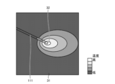
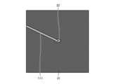
- a diagram showing an example of a contour map of temperature distribution in the imaging area of a two-color temperature camera Diagram schematically showing an example of emissivity distribution in the imaging range of a two-color temperature camera Flowchart illustrating an example of a procedure of a method for controlling the additive manufacturing apparatus according to Embodiment 1
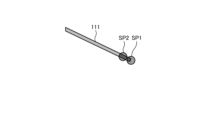
- Diagram schematically showing an example of a contour map of preheated feed material and temperature distribution near the processing area Diagram schematically showing an example of a focused spot split by a diffraction grating
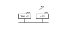
- a diagram showing an example of the configuration of an additive manufacturing apparatus according to Embodiment 3 A diagram showing an example of the hardware configuration of the control unit of the additive manufacturing apparatus according to Embodiments 1 to 3.
- FIG. 1 is a diagram schematically showing an example of the configuration of an additive manufacturing apparatus according to a first embodiment.
- the additive manufacturing apparatus 1 is an apparatus that melts a supply material 111 using a processing beam B and adds the melted material onto a workpiece 31 to form a target shape.
- the additive manufacturing apparatus 1 includes a material supply unit 11 that supplies a supply material 111 onto a workpiece 31, a processing beam source 12 that emits a processing beam B, and a processing beam B that irradiates the supply material 111 and the workpiece 31.
- a processing head 13 is provided.
- the material supply unit 11 supplies a supply material 111 to the processing area.
- the material supply section 11 can change the material supply speed, which is the speed at which the supply material 111 is supplied onto the workpiece 31, according to instructions from the control section 17, which will be described later.
- the feed material 111 is fed toward the processing area, the feeding angle and direction are not particularly limited. In the example of FIG. 1, a case is shown in which the supply material 111 is supplied to the workpiece 31 from diagonally above the workpiece 31 and the processing beam B is made perpendicularly incident on the workpiece 31, but the supply material 111 The processing beam B may be supplied perpendicularly to the workpiece 31 and the processing beam B may be incident obliquely.
- the supply material 111 is a metal wire, which is a metal formed into a wire shape. Additionally, the metal wire has a different chemical composition than the workpiece 31.
- feed material 111 corresponds to a first feed material.
- the additive manufacturing apparatus 1 of Embodiment 1 performs additive manufacturing between different materials, and has a plurality of material supply units 11 that supply materials having different chemical compositions (not shown). That is, in FIG. 1, the workpiece 31 is shaped by supplying a supply material having a different chemical composition from the illustrated supply material 111 from a material supply unit (not shown).
- the processing beam source 12 emits a processing beam B.
- the processing beam source 12 is a laser oscillator that emits a laser beam such as a solid-state laser, a gas laser, or a semiconductor laser.
- the processing beam source 12 is an electron gun.
- the processing head 13 irradiates the processing beam B emitted from the processing beam source 12 onto the workpiece 31 .
- the processing beam B is a laser beam
- the processing beam source 12 and the processing head 13 are connected by an optical fiber 14.
- the laser beam is transmitted through the optical fiber 14.
- the processing head 13 has a drive mechanism (not shown).
- the drive mechanism drives the processing head 13 in the horizontal direction with respect to the workpiece 31. Thereby, the processing head 13 can scan the processing beam B over the workpiece 31.
- the drive mechanism can change the scan speed, which is the speed at which the processing beam B scans the workpiece 31, according to instructions from the control unit 17.
- the drive mechanism may drive the processing head 13 in a direction perpendicular to the workpiece 31.
- the supply material 111, the workpiece 31, or both the supply material 111 and the workpiece 31 are heated and melted, thereby causing melting.
- a pond 32 is formed.
- the formed high-temperature molten pool 32 is cooled on the workpiece 31, cools below its melting point, and solidifies, thereby adding metal onto the workpiece 31.
- beads, which are linear additional layers, are formed, and by repeatedly stacking the beads, a three-dimensional object of an arbitrary shape can be modeled. Can be done.
- the additive manufacturing apparatus 1 includes a two-color temperature camera 15 that images a predetermined area including the processing area on the workpiece 31 that is irradiated with the processing beam B using light in at least two wavelength bands.
- the two-color temperature camera 15 measures the temperature distribution in the processing area and its surrounding area.
- the area where the two-color temperature camera 15 measures the temperature distribution will be referred to as an imaging area.
- the two-color temperature camera 15 is a radiation thermometer that obtains a two-dimensional temperature distribution, and obtains the surface temperature of an object included in its field of view by measuring the thermal radiance from the object.
- the two-color temperature camera 15 is installed outside the processing head 13, as shown in FIG. However, this is just an example, and it may be built into the processing head 13 by sharing a part of the optical system with the processing beam B.
- the two-color temperature camera 15 in the first embodiment is installed so as to include the molten pool 32, the feed material 111, and the workpiece 31 around the molten pool 32, that is, the processing area, in its field of view.
- the two-color temperature camera 15 it becomes possible to simultaneously measure the temperature distribution of the feed material 111, the workpiece 31, and the molten pool 32, which have different chemical compositions, in real time during processing.
- the additive manufacturing apparatus 1 uses a display 16 that displays information indicating the state of the processing area to the operator and measurement results from the two-color temperature camera 15 to set parameters for operating the additive manufacturing apparatus 1 during processing. It includes a control section 17 that controls a certain machining parameter and displays information indicating the state of the machining area on a display 16.
- the display 16 displays temperature distribution information that is information indicating the temperature distribution of the imaging area including the processing area calculated by the control unit 17.
- An example of the display 16 is a liquid crystal display panel.
- the display 16 corresponds to a display section.
- the control unit 17 calculates the temperature distribution of the imaging area including the processing area from the measurement results by the two-color temperature camera 15, and controls the processing parameters based on the calculated temperature distribution.
- the control unit 17 calculates the radiance ratio from the light intensity of each pixel in the image of the imaging region in two similar wavelength bands by the two-color temperature camera 15, and calculates the temperature at each pixel from the radiance ratio. As a result, a temperature distribution obtained by determining the temperature at each pixel of the image in the imaging region is obtained.
- the control unit 17 displays temperature distribution information, which is information indicating the temperature distribution in the imaging region, on the display 16.
- the control unit 17 uses a contour map to display the temperature distribution of the imaging region on the display 16 as temperature distribution information. As a result, the temperature of the imaging area measured by the two-color temperature camera 15 is visually displayed.
- FIG. 2 is a diagram showing an example of a contour map of temperature distribution in an imaging region of a two-color temperature camera. As shown in FIG. 2, the results of simultaneously measuring the temperature of the molten pool 32, the solid workpiece 31 around it, and the feed material 111 just before being conveyed to the molten pool 32 are displayed on the display 16. be done. In the contour diagram shown in FIG.
- the temperature of the feed material 111 is the highest.
- the operator can visually check the temperature, the temperature of the molten pool 32, the temperature distribution in the imaging region, and the maximum temperature in the imaging region in a short time.
- the control unit 17 obtains the measured temperature of the molten pool 32 using the temperature distribution information calculated from the results measured by the two-color temperature camera 15, and controls the temperature so that the measured temperature of the molten pool 32 approaches a preset target value.
- the output of the processing beam B of the processing beam source 12, in this case the laser output is controlled.
- the control unit 17 sets the upper and lower limit values T H and T L of the set temperature range as the target temperature value.
- the control unit 17 reduces the laser output when the measured temperature T of the molten pool 32 measured by the two-color temperature camera 15 is larger than the upper limit value T H , that is, when T> TH .
- the control unit 17 increases the laser output when the measured temperature T of the molten pool 32 is smaller than the lower limit T L , that is, when T ⁇ T L. By performing such control, the amount of energy incident on the molten pool 32 is adjusted.
- the control unit 17 slows down the scanning speed that is the scanning speed of the processing beam B to increase the amount of heat input per unit area of the workpiece 31, and at the same time increases the amount of heat input per unit area of the workpiece 31.
- the material supply rate which is the supply rate of the workpiece 111, is slowed down and controlled to keep the modeling volume per unit area of the workpiece 31 constant.
- the control unit 17 increases the scanning speed of the processing beam B to reduce the amount of heat input per unit area of the workpiece 31, and at the same time increases the material supply speed of the supply material 111.
- the modeling volume per unit area of the workpiece 31 may be kept constant. Note that in the first embodiment, the scanning speed of the processing beam B is also the speed at which the processing head 13 is scanned.
- control unit 17 controls processing parameters including at least one selected from the output of the processing beam B of the processing beam source 12, the scanning speed of the processing beam B, and the material supply rate of the supply material 111.
- the control unit 17 also calculates the emissivity at each position in the imaging range captured by the two-color temperature camera 15 using the temperature measured by the two-color temperature camera 15, and provides information indicating the distribution of emissivity in the imaging range.
- the emissivity distribution information is displayed on the display section. Emissivity is measured for each pixel of the two-color temperature camera 15.
- An ideal object whose absorption rate is 1 for light of all wavelengths is called a black body, and the spectral radiance I bb due to thermal radiation from the black body is expressed by Planck's law as shown in the following equation (1).
- T is the absolute temperature
- ⁇ is the wavelength of light
- a and B are known constants consisting of scientific constants.
- I bb ( ⁇ , T) A/ ⁇ 5 (exp(B/ ⁇ T)-1) ⁇ ...(1)
- emissivity The radiance of thermal radiation emitted by an object that is not a black body is weaker than the radiance of a black body, and the coefficient representing the ratio is called emissivity. It is generally known as Kirchhoff's law that emissivity coincides with absorption rate. Spectral radiance I from an actual object is expressed by the following equation (2), where emissivity is ⁇ ( ⁇ ).
- I sys (T) ⁇ C( ⁇ )A/ ⁇ 5 (exp(B/ ⁇ T)-1) ⁇ d ⁇ ...(3)
- a known technique is to measure temperature by approximating the emissivity to be the same when radiance is measured in two similar wavelength bands. This technique is disclosed, for example, in Japanese Patent Laid-Open No. 2004-45306.
- the two-color temperature camera 15 is a method of measuring temperature using this technique.
- the two-color temperature camera 15 can measure temperature without providing emissivity. Therefore, it is also possible to calculate the emissivity from the measured temperature. From the radiance I obs and I sys measured by the two-color temperature camera 15, the emissivity ⁇ is calculated from the following equation (4).
- the radiance I obs is determined based on the temperature calculated for each pixel of the two-color temperature camera 15 from the relationship at a determined wavelength ⁇ between the temperature of the member to be measured and the radiance. It is the radiance at the wavelength.
- the radiance I sys is the radiance of the black body at a predetermined wavelength, which is determined based on the temperature calculated for each pixel of the two-color temperature camera 15 from the predetermined relationship between the temperature and the radiance of the black body. It is.
- control unit 17 displays the emissivity distribution information of the imaging area including the processing area obtained by the two-color temperature camera 15 on the display 16.
- control unit 17 desirably displays the temperature distribution information and the emissivity distribution information on the display 16 by arranging them side by side on one screen. This allows the operator to check the emissivity distribution displayed on the display 16.
- the emissivity of the workpiece 31 and the feed material 111 is uniform, in the molten pool 32 and its surroundings, the workpiece 31 and the feed material 111 may be mixed, alloyed, or a compound or oxide may be formed.
- the emissivity changes due to the following reasons. That is, by generating an emissivity distribution, changes in the chemical state or composition around the processing area can be visualized during processing.
- FIG. 3 is a diagram schematically showing an example of the emissivity distribution in the imaging range of the two-color temperature camera.
- the feed material 111 and the workpiece 31 have a constant emissivity, and the emissivity is different near the molten pool 32. That is, different compositions or chemical states are realized near the molten pool 32, and this appears as a difference in emissivity.
- the emissivity distribution becomes a visualization of changes in the chemical state or composition in the imaging range.
- the change in composition can also be referred to as the spatial distribution of the composition.
- information indicating the processing state can be provided to the operator in real time. Then, the operator estimates the machining quality from the spatial distribution of the visualized chemical state or composition among the information indicating the machining state. Note that the work of estimating processing quality from the visualized chemical state or spatial distribution of composition depends on the combination of the workpiece 31 and the feed material 111, and the operator must estimate the processing quality based on empirically obtained information. Estimate processing quality.
- FIG. 4 is a flowchart illustrating an example of the procedure of the control method for the additive manufacturing apparatus according to the first embodiment.
- the control unit 17 of the additive manufacturing apparatus 1 acquires images in two similar wavelength bands in the imaging region measured by the two-color temperature camera 15 (step S11).
- the control unit 17 calculates the radiance ratio in each pixel of the two acquired images, and calculates the temperature of each pixel from the radiance ratio (step S12).
- the temperature is calculated from the radiance ratio using information that has been calculated in advance about the relationship between the radiance ratio of two wavelength bands and the surface temperature of the measurement target.
- the control unit 17 generates temperature distribution information indicating the temperature distribution of each pixel in the imaging region (step S13).
- the control unit 17 displays the temperature distribution information on the display 16 (step S14).
- the control unit 17 also calculates the radiance I obs at a predetermined wavelength and the blackbody radiance I sys at the predetermined wavelength from the temperature at each pixel, and calculates the emissivity of each pixel in the imaging area. is calculated (step S15).
- the control unit 17 generates emissivity distribution information indicating the emissivity distribution of each pixel in the imaging region (step S16).
- the control unit 17 displays the emissivity distribution information on the display 16 (step S17). At this time, when there is only one display 16, it is preferable that the control unit 17 causes the display 16 to display the emissivity distribution information together with the temperature distribution information. By doing so, it is possible to provide the operator with the temperature distribution in the processing region as well as the emissivity distribution corresponding to changes in the chemical state or composition in the processing region.
- the control unit 17 acquires the temperature in the molten pool 32 from the temperature distribution information (step S18), and determines whether the temperature of the molten pool 32 is higher than the upper limit of the set temperature range (step S19).
- the set temperature range is the temperature range of the molten pool 32 that is determined by the combination of the workpiece 31 and the feed material 111 and that is desired to be maintained during the shaping process.
- the control unit 17 can acquire the temperature in the molten pool 32 by estimating that the highest region in the temperature distribution information is the molten pool 32 . If the temperature of the molten pool 32 is below the upper limit of the set temperature range (No in step S19), the control unit 17 determines whether the temperature of the molten pool 32 is lower than the lower limit of the set temperature range. (Step S20).
- step S20 If the temperature of the molten pool 32 is equal to or higher than the lower limit of the set temperature range (No in step S20), the temperature of the molten pool 32 is controlled to be within the set temperature range. Therefore, the process returns to step S11 without performing any special processing.
- the control unit 17 sets at least one of the processing parameters including the laser output, the scanning speed of the processing beam B, and the material supply rate of the supply material 111 so that the temperature of the molten pool 32 is the set temperature. It is changed so that it falls within the range (step S21). In one example, when the temperature of the molten pool 32 is higher than the upper limit of the set temperature range, the control unit 17 reduces the laser output.
- control unit 17 increases the laser output, or in other examples, slows down the scanning speed of the processing beam B, and Slow down the material feed rate of the feed material 111. After that, the process returns to step S11.
- the additive manufacturing apparatus 1 includes a material supply unit 11 that supplies a feed material 111 having a chemical composition different from that of the workpiece 31 toward a processing area of the workpiece 31, and A processing beam source 12 that supplies a processing beam B that heats an object 31 toward a processing area, a processing head 13 that irradiates the processing area with the processing beam B from the processing beam source 12, and an imaging area that includes at least the processing area.
- a two-color temperature camera 15 that captures images using light in two wavelength bands is provided.
- the additive manufacturing apparatus 1 determines that the workpiece 31 and the feed material 111 in the processing area are melted, and the workpiece 31 and the feed material 111 are melted based on the measurement results by the two-color temperature camera 15.
- Temperature distribution information indicating the temperature distribution of the imaging region including the temperature of the molten pool 32 is calculated, and based on the temperature distribution information, the output of the processing beam B of the processing beam source 12 and the scan speed, which is the speed at which the processing beam B is scanned, are calculated. , and a control unit 17 that controls processing parameters including at least one selected from the following: , and the material supply rate of the supply material 111.
- processing parameters including at least one selected from the output of the processing beam source 12, the scanning speed of the processing beam B, and the material supply speed of the supply material 111 can be controlled with high precision, compared to the conventional method. It is possible to realize additive manufacturing between different materials with high precision.
- control unit 17 displays temperature distribution information on the display 16. This allows the operator to understand the temperature distribution in the processing area. Further, the control unit 17 causes the display 16 to display emissivity distribution information indicating the emissivity of each pixel in the imaging area determined from the measurement results by the two-color temperature camera 15. The emissivity distribution visualizes changes in the chemical state or composition in the imaging range. This allows the operator to estimate processing quality from the relationship between changes in chemical state or composition and processing quality.
- FIG. 5 is a diagram schematically showing an example of the configuration of the additive manufacturing apparatus according to the second embodiment.
- FIG. 5 shows a case where the processing beam B is a laser beam L. Note that the same components as in FIG. 1 are given the same reference numerals, and their explanations will be omitted.
- a processing head 13A is different from that in the first embodiment. Further, in the additive manufacturing apparatus 1A according to the second embodiment, the two-color temperature camera 15 is provided at a position within the processing head 13A where it can image the processing area.
- the processing head 13A includes a transmission optical system 130 that emits the laser beam L from the optical fiber 14 from the output end, and a preheating optical element 132 that branches part of the laser beam LB to preheat the feed material 111.
- the preheating optical element 132 corresponds to a preheating section. In the example of FIG.
- the processing head 13A includes a collimating lens 131 that converts the laser beam L from the optical fiber 14 into a parallel beam, a preheating optical element 132 that irradiates part of the laser beam L onto the feed material 111, and a preheating It includes a reflecting mirror 133 that reflects the laser beams LA and LB that have passed through the optical element 132, and a condenser lens 134 that focuses the laser beams LA and LB reflected by the reflecting mirror 133 onto a processing position.
- the collimating lens 131, the reflecting mirror 133, and the condensing lens 134 are just examples, and any configuration may be used as long as the laser beam L from the optical fiber 14 can be focused on the processing position. Good too.
- a preheating optical element 132 which is a preheating section, is inserted into a transmission optical system 130 that guides a laser beam L, which is a processing beam B, to a processing area.
- a part of the laser beam L can be irradiated onto the feed material 111 before entering the processing area, and the feed material 111 can be preheated.
- the laser beam L is irradiated as the laser beam LA to the processing area where the molten pool 32 is formed, but when the preheating optical element 132 is inserted.
- part of the laser beam LB of the laser beam L is irradiated onto the feed material 111 before entering the processing area. That is, the vicinity of the tip of the feed material 111 is preheated.
- FIG. 6 is a diagram schematically showing an example of a contour map of the preheated feed material and the temperature distribution near the processing area.
- the feed material 111 is at a high temperature at the preheating location.
- the preheating point for feed material 111 is near the processing area.
- the preheating optical element 132 to be inserted is any optical element designed according to the processing purpose, such as a lens, lens array, diffraction grating, metalens, etc., or a spatial phase modulator. These preheating optical elements 132 slightly modulate the processing beam B, thereby changing the shape of the focused spot in the processing area.
- the preheating optical element 132 in FIG. 5 is a diffraction grating, and by modulating the traveling direction of a part of the laser beam L that is the processing beam B, the laser beam LA irradiated onto the processing area and the supply material 111 are It is made to branch into the irradiated laser beam LB. As a result, the focused spot in the processing area is split into two.
- FIG. 7 is a diagram schematically showing an example of a focused spot split by a diffraction grating.
- the focused spot SP1 heats the processing area, and the branched focused spot SP2 preheats the feed material 111.
- the profile may be adjusted in accordance with the preheating conditions and processing conditions, such as by increasing the beam diameter of the preheating optical element 132 or forming an elliptical spot.
- the processing head 13A includes a transmission optical system 130 that emits the laser beam L from the optical fiber 14 from the output end, and a preheating optical element that branches part of the laser beam L to preheat the feed material 111. It has 132.
- the laser beam L is branched into two laser beams LA and LB, one laser beam LA is irradiated onto the processing area, and the other laser beam LB is irradiated onto the feed material 111 just before entering the processing area. , preheat the feed material 111.
- the feed material 111 that has entered the processing area is quickly melted, allowing stable continuous processing.
- FIG. 8 is a diagram illustrating an example of the configuration of an additive manufacturing apparatus according to the third embodiment. Note that the same components as those in Embodiment 1 are given the same reference numerals, and their explanations will be omitted.
- the additive manufacturing apparatus 1B further includes a material supply unit 18 that supplies powdered supply material 181 to the processing area.
- the material supply unit 18 injects powdered supply material 181 into the processing area.
- the material supply unit 18 can change the material supply rate, which is the rate at which the powdered supply material 181 is supplied onto the workpiece 31, according to instructions from the control unit 17.
- the powdered feed material 181 is fed toward the processing area, but the feeding angle and direction are not particularly limited.
- the wire-shaped feed material 111 corresponds to a first feed material and powder-like feed material 181 corresponds to a second feed material.
- the wire-shaped feed material 111 has the same composition as the workpiece 31 in FIG. Let us take as an example the case of forming .
- Joint surfaces of dissimilar materials are generally more brittle than interfaces of similar materials. This may cause processing failure when modeling different materials. Therefore, when modeling different materials on the workpiece 31, if the composition is changed little by little for each layer so that the composition distribution at the bonding surface of the different materials becomes a gradation, a strong bonding interface can be created. known to be obtained.
- a bonding interface whose composition is changed little by little along a gradation pattern will be referred to as a gradation layer.
- the gradation layer is, for example, a layer made of an alloy of wire-like feed material 111 and powder-like feed material 181.
- the composition obtained after heating, melting, and mixing a plurality of materials is determined by the heating and cooling paths. That is, it is determined by the temperature process of the molten pool 32. If the temperature of the molten pool 32 is inappropriate, alloying will not occur as designed, and metals will precipitate or compounds such as oxides will form.
- the alloying process is designed by calculating in advance the phase diagram for the composition at a certain temperature. To realize the designed process, it is necessary to maintain a constant temperature during processing. Since the additive manufacturing apparatus 1B of the third embodiment includes the two-color temperature camera 15 for measuring the temperature of the processing area, the temperature of the molten pool 32 can be accurately measured regardless of the composition of the molten pool 32 as described above. Is possible.
- the control unit 17 controls the processing parameters as described in the first embodiment so that the measured temperature of the molten pool 32 becomes the temperature in the designed process.
- control of the composition is achieved by controlling the supply amount ratio of the wire-shaped feed material 111 and the powder-like feed material 181 having a chemical composition different from that of the wire-shaped feed material 111. That is, the control unit 17 controls the composition of the additional layer formed by changing the material supply rate of the wire-shaped supply material 111 and the material supply rate of the powdered supply material 181. Further, the control unit 17 uses the temperature distribution information calculated from the measurement results by the two-color temperature camera 15 to adjust the output of the processing beam B and the scan speed so that the temperature of the molten pool 32 falls within a predetermined range. control. This makes it possible to obtain a strong bonding interface when modeling dissimilar materials.
- the powdered supply material 181 and the wire-shaped supply material 111 are supplied at the same time when an interface between different materials is to be shaped. After modeling the interface between different materials, a wire-shaped supply material 111 or powdered supply material 181 is used, which is not the material used before modeling the interface between different materials.
- the additive manufacturing apparatus 1B includes a material supply section 11 that supplies a wire-shaped supply material 111 and a material supply section 18 that supplies a powdered supply material 181.
- the control unit 17 controls the temperature of the molten pool 32 based on the measurement results from the two-color temperature camera 15 so that the temperature of the molten pool 32 becomes the temperature of the process designed in advance based on the phase diagram.
- the processing parameters are controlled, and the feed ratio between the wire-like feed material 111 and the powder-like feed material 181 is controlled. As a result, a three-dimensional structure having a strong bonding interface between different materials can be obtained.
- the wire-shaped supply material 111 and the powder-shaped supply material 181 are made of metal.
- the metal may be not only a material made of a single metallic element, but also an alloy or an intermetallic compound.
- FIG. 9 is a diagram illustrating an example of the hardware configuration of the control unit of the additive manufacturing apparatus according to the first to third embodiments.
- the control unit 17 can be realized by the control circuit 400 shown in FIG. 9, that is, the processor 401 and the memory 402.
- the processor 401 is a CPU (also referred to as a central processing unit, processing unit, arithmetic unit, microprocessor, microcomputer, processor, or DSP (Digital Signal Processor)) or a system LSI (Large Scale Integration).
- the memory 402 is a RAM (Random Access Memory) or a ROM (Read Only Memory).
- control unit 17 The functions of the control unit 17 are realized by the processor 401 reading and executing a control program stored in the memory 402, which is a program for executing processing in the control unit 17. It can also be said that this control program causes the computer to execute the method of controlling the additive manufacturing apparatuses 1, 1A, and 1B in the control section 17.
- the control program executed by the control unit 17 calculates temperature distribution information and emissivity distribution information of the imaging area from the measurement results of the two-color temperature camera 15, and executes a process of controlling processing parameters based on the temperature distribution information in a module. It has a modular structure, which is loaded onto the main memory, and which is generated on the main memory. Note that the processing parameters include the output of the processing beam source 12, the scanning speed of the processing beam B, and the material supply speed of the material supply units 11 and 18.
- the memory 402 stores data used when modeling a three-dimensional object.
- the memory 402 is also used as temporary memory when the processor 401 executes various processes.
- the control program executed by the processor 401 may be an installable or executable file stored in a computer-readable storage medium and provided as a computer program product. Further, the control program executed by the processor 401 may be provided to the control unit 17 of the additive manufacturing apparatus 1, 1A, 1B via a network such as the Internet.
- control unit 17 may be realized by dedicated hardware. Furthermore, some of the functions of the control unit 17 may be realized by dedicated hardware, and some may be realized by software or firmware.
- 1, 1A, 1B additive manufacturing device 11, 18 material supply unit, 12 processing beam source, 13, 13A processing head, 14 optical fiber, 15 two-color temperature camera, 16 display, 17 control unit, 31 workpiece, 32 Molten pool, 111, 181 Supply material, 130 Transmission optical system, 131 Collimating lens, 132 Preheating optical element, 133 Reflection mirror, 134 Condensing lens, B Processing beam, L, LA, LB Laser light, SP1, SP2 collection light spot.
Landscapes
- Engineering & Computer Science (AREA)
- Physics & Mathematics (AREA)
- Optics & Photonics (AREA)
- Chemical & Material Sciences (AREA)
- Materials Engineering (AREA)
- Mechanical Engineering (AREA)
- Plasma & Fusion (AREA)
- Manufacturing & Machinery (AREA)
- Health & Medical Sciences (AREA)
- Toxicology (AREA)
- Welding Or Cutting Using Electron Beams (AREA)
- Laser Beam Processing (AREA)
Abstract
付加製造装置は、第1材料供給部と、加工ビーム源と、加工ヘッドと、2色温度カメラと、制御部と、を備える。第1材料供給部は、加工領域に向けて被加工物と異なる化学組成をもつ第1供給材料を供給する。加工ビーム源は、第1供給材料および被加工物を加熱する加工ビームを出力する。加工ヘッドは、加工ビームを加工領域に照射する。2色温度カメラは、加工領域を含む撮像領域を少なくとも2つの波長帯の光で撮像する。制御部は、2色温度カメラによる計測結果に基づいて、加工領域における被加工物、第1供給材料、並びに被加工物および第1供給材料が溶融した溶融池の温度を含む温度分布情報を算出する。また、制御部は、温度分布情報に基づいて、加工ビーム源の加工ビームの出力、加工ビームをスキャンする速度であるスキャンスピード、および第1供給材料の供給速度である材料供給速度から選択される少なくとも1つを含む加工パラメータを制御する。
Description
本開示は、3次元造形物を製造する付加製造装置に関する。
3次元造形物を製造する付加製造装置において、造形中にリアルタイムで3次元造形物の品質を推定する技術が知られている。特許文献1には、3次元造形物が造形される造形台上に、3次元造形物の材料を噴射する材料噴射部と、噴射された材料に加工ビームの一例である光線を照射する光線照射部と、3次元造形物の造形中に、3次元造形物の造形状態を監視するためのモニタリングデータを取得するデータ取得部と、モニタリングデータに基づいて、3次元造形物の造形品質を推定する造形品質推定部と、を備える付加製造装置が開示されている。
ところで、付加製造装置における被加工物の温度の算出には、一般的に、被加工物の組成によって異なる放射率が用いられる。付加製造装置での3次元造形物の製造において、被加工物上に加工ビームが照射される領域である加工領域における3次元造形物の組成が複数の材料を含む場合、一例では供給材料と被加工物との組成が異なる場合、が存在する。このような場合には、放射率を用いた正確な温度の計測を実行することが困難であるという問題があった。加工領域の正確な温度を計測することができないと、加工ビームのスキャンスピード、供給材料の供給速度を含む加工パラメータの制御を高精度に行うことができない。この結果、付加造形によって形成される3次元造形物の形状と目標形状との間のずれが大きくなるという問題があった。
本開示は、上記に鑑みてなされたものであって、被加工物に対して被加工物とは異なる化学組成の供給材料が付加造形される場合でも、異種材料間の付加造形を従来に比して高精度に実現することができる付加製造装置を得ることを目的とする。
上述した課題を解決し、目的を達成するために、本開示に係る付加製造装置は、第1材料供給部と、加工ビーム源と、加工ヘッドと、2色温度カメラと、制御部と、を備える。第1材料供給部は、被加工物の加工領域に向けて被加工物と異なる化学組成をもつ第1供給材料を供給する。加工ビーム源は、第1供給材料および被加工物を加熱する加工ビームを出力する。加工ヘッドは、加工ビーム源からの加工ビームを加工領域に照射する。2色温度カメラは、加工領域を含む撮像領域を少なくとも2つの波長帯の光で撮像する。制御部は、2色温度カメラによる計測結果に基づいて、加工領域における被加工物、第1供給材料、並びに被加工物および第1供給材料が溶融した溶融池の温度を含む撮像領域の温度分布を示す温度分布情報を算出する。また、制御部は、温度分布情報に基づいて、加工ビーム源の加工ビームの出力、加工ビームをスキャンする速度であるスキャンスピード、および第1供給材料の供給速度である材料供給速度から選択される少なくとも1つを含む加工パラメータを制御する。
本開示に係る付加製造装置は、被加工物に対して被加工物とは異なる化学組成の供給材料が付加造形される場合でも、異種材料間の付加造形を従来に比して高精度に実現することができるという効果を奏する。
以下に、本開示の実施の形態に係る付加製造装置を図面に基づいて詳細に説明する。
実施の形態1.
図1は、実施の形態1に係る付加製造装置の構成の一例を模式的に示す図である。付加製造装置1は、供給材料111を加工ビームBにより溶融させて被加工物31上へ付加することで目標とする形状を造形する装置である。付加製造装置1は、供給材料111を被加工物31上に供給する材料供給部11と、加工ビームBを出射する加工ビーム源12と、供給材料111および被加工物31に加工ビームBを照射する加工ヘッド13と、を備える。
図1は、実施の形態1に係る付加製造装置の構成の一例を模式的に示す図である。付加製造装置1は、供給材料111を加工ビームBにより溶融させて被加工物31上へ付加することで目標とする形状を造形する装置である。付加製造装置1は、供給材料111を被加工物31上に供給する材料供給部11と、加工ビームBを出射する加工ビーム源12と、供給材料111および被加工物31に加工ビームBを照射する加工ヘッド13と、を備える。
材料供給部11は、加工領域に供給材料111を供給する。材料供給部11は、供給材料111を被加工物31上に供給する速度である材料供給速度を、後述する制御部17からの指示に従って変更可能である。供給材料111は加工領域に向かって供給されるが、供給角度、方向は、特に限定されない。図1の例では、供給材料111を被加工物31の斜め上方から被加工物31に供給し、加工ビームBを被加工物31に対して垂直に入射させる場合を示したが、供給材料111を被加工物31に対して垂直に供給し、加工ビームBを斜めから入射させてもよい。実施の形態1では、供給材料111はワイヤ状に成型された金属である金属ワイヤであるとする。また、金属ワイヤは、被加工物31とは異なる化学組成を有する。一例では、供給材料111は、第1供給材料に対応する。なお、実施の形態1の付加製造装置1は、異種材料間の付加造形を行うものであり、図示しないが異なる化学組成の供給材料を供給する複数の材料供給部11を有する。つまり、図1では、被加工物31は、図示される供給材料111とは化学組成が異なる供給材料を図示しない材料供給部から供給されることによって造形されたものである。
加工ビーム源12は、加工ビームBを出射する。加工ビームBがレーザ光である場合には、加工ビーム源12は、固体レーザ、ガスレーザ、半導体レーザ等のレーザ光を出射するレーザ発振器である。加工ビームBが電子線である場合には、加工ビーム源12は、電子銃である。
加工ヘッド13は、加工ビーム源12から出射される加工ビームBを被加工物31上に照射する。なお、加工ビームBがレーザ光である場合には、加工ビーム源12と加工ヘッド13との間は光ファイバ14によって接続される。この場合には、光ファイバ14によってレーザ光が伝送される。また、加工ヘッド13は、図示しない駆動機構を有する。駆動機構は、加工ヘッド13を被加工物31に対して水平方向に駆動させる。これによって、加工ヘッド13は、加工ビームBを被加工物31上でスキャンさせることができる。駆動機構は、制御部17からの指示に従って、被加工物31上で加工ビームBをスキャンさせる速度であるスキャンスピードを変更可能である。なお、駆動機構は、加工ヘッド13を被加工物31に対して垂直方向に駆動させてもよい。
被加工物31上の加工ビームBが照射される領域である加工領域では、供給材料111、被加工物31、または供給材料111と被加工物31との両方が加熱され溶融することで、溶融池32が形成される。形成された高温の溶融池32が被加工物31上で冷却され、融点を下回り、凝固することで金属が被加工物31上に付加される。そして、加工ヘッド13を移動させつつ供給材料111を連続的に供給することで線状の付加層であるビードが形成され、繰り返しビードを積み重ねることによって任意の形状の3次元造形物を造形することができる。
付加製造装置1は、被加工物31上の加工ビームBが照射される領域である加工領域を含む定められた領域を少なくとも2つの波長帯の光で撮像する2色温度カメラ15を備える。
2色温度カメラ15は、加工領域とその周辺領域の温度分布を計測する。以下では、2色温度カメラ15が温度分布を計測する領域は、撮像領域と称される。2色温度カメラ15は、2次元の温度分布を取得する放射温度計であり、視野に含まれる物体の表面温度を物体からの熱放射輝度を計測することで求める。2色温度カメラ15は、一例では図1に示されるように、加工ヘッド13の外部に設置される。ただし、これは一例であり、加工ビームBと光学系の一部を共有するなどの方法で加工ヘッド13に内蔵される構成であってもよい。
実施の形態1における2色温度カメラ15は、溶融池32、供給材料111および溶融池32の周辺の被加工物31、すなわち加工領域を視野に含むよう設置される。2色温度カメラ15を使うことによって、異なる化学組成からなる供給材料111、被加工物31および溶融池32の温度分布を加工中にリアルタイムで同時計測することが可能となる。
付加製造装置1は、作業者に加工領域の状態を示す情報を表示する表示器16と、2色温度カメラ15での計測結果を用いて、付加製造装置1を加工時に動作させる際のパラメータである加工パラメータを制御するとともに、加工領域の状態を示す情報を表示器16に表示する制御部17と、を備える。
表示器16は、制御部17で算出される加工領域を含む撮像領域の温度分布を示す情報である温度分布情報を表示する。表示器16の一例は、液晶表示パネルである。表示器16は、表示部に対応する。
制御部17は、2色温度カメラ15での計測結果から加工領域を含む撮像領域の温度分布を算出し、算出した温度分布に基づいて、加工パラメータを制御する。制御部17は、2色温度カメラ15での2つの近い波長帯における撮像領域の画像における各画素の光強度から放射輝度比を算出し、放射輝度比から各画素における温度を算出する。これによって、撮像領域の画像の各画素における温度を求めた温度分布が得られる。制御部17は、撮像領域における温度分布を示す情報である温度分布情報を表示器16に表示する。
一例では、制御部17は、等高線図を用いて撮像領域の温度分布を表したものを温度分布情報として表示器16に表示する。これによって、2色温度カメラ15で計測した撮像領域の温度が視覚的に表示される。図2は、2色温度カメラの撮像領域における温度分布についての等高線図の一例を示す図である。図2に示されるように、溶融池32とその周辺の固体状態の被加工物31および溶融池32に搬送される直前の供給材料111の温度を同時に計測した結果が、表示器16にて表示される。図2に示される等高線図では、加工領域の中央付近、すなわち溶融池32で最も温度が高く、加工領域から離れるほど温度が低くなっている被加工物31の温度に加えて、供給材料111の温度、溶融池32の温度、撮像領域における温度分布、撮像領域における最高温度を作業者が短い時間で視認することができる。
制御部17は、2色温度カメラ15で計測された結果から算出した温度分布情報を用いて溶融池32の計測温度を取得し、溶融池32の計測温度が予め設定された目標値に近づくように、加工ビーム源12の加工ビームBの出力、この場合にはレーザ出力を制御する。具体的には、制御部17は、設定温度範囲の上下限値TH,TLを温度の目標値に設定する。制御部17は、2色温度カメラ15で計測された溶融池32の計測温度Tが上限値THよりも大きい場合、すなわちT>THの場合に、レーザ出力を低下させる。制御部17は、溶融池32の計測温度Tが下限値TLよりも小さい場合、すなわちT<TLの場合に、レーザ出力を上昇させる。このような制御を行うことで溶融池32に入射するエネルギ量が調整される。
また、制御部17は、T<TLである場合には、加工ビームBをスキャンする速度であるスキャンスピードを遅くして被加工物31の単位面積あたりの入熱量を増やすと同時に、供給材料111の供給速度である材料供給速度を遅くして被加工物31の単位面積あたりの造形体積を一定に保つように制御する。制御部17は、T>THの場合には、加工ビームBのスキャンスピードを速くして被加工物31の単位面積あたりの入熱量を減らすと同時に、供給材料111の材料供給速度を速くして被加工物31の単位面積あたりの造形体積を一定に保つようにしてもよい。なお、実施の形態1では、加工ビームBのスキャンスピードは、加工ヘッド13をスキャンする速度でもある。
このように、制御部17は、加工ビーム源12の加工ビームBの出力、加工ビームBのスキャンスピード、および供給材料111の材料供給速度から選択される少なくとも1つを含む加工パラメータを制御する。
また、制御部17は、2色温度カメラ15で計測した温度を用いて2色温度カメラ15で撮像された撮像範囲の各位置における放射率を算出し、撮像範囲における放射率の分布を示す情報である放射率分布情報を表示部に表示する。放射率は、2色温度カメラ15の画素ごとに測定される。ここで、2色温度カメラ15での計測結果を用いた温度分布および放射率分布の算出について説明する。あらゆる波長の光に対して吸収率が1である理想物体を黒体と呼び、黒体からの熱放射による分光放射輝度Ibbはプランクの法則により次式(1)のように表される。(1)式において、Tは絶対温度であり、λは光の波長であり、A,Bは科学定数から成る既知の定数である。
Ibb(λ,T)=A/{λ5(exp(B/λT)-1)} ・・・(1)
黒体でないある物体が発する熱放射の放射輝度は黒体の放射輝度よりも弱く、その比を表す係数は放射率と呼ばれる。放射率は吸収率と一致することがキルヒホッフの法則として一般に知られている。実際の物体からの分光放射輝度Iは、放射率をε(λ)とすると次式(2)で表される。
I(λ,T)=ε(λ)A/{λ5(exp(B/λT)-1)} ・・・(2)
実測する黒体の放射輝度Isysは、カメラの感度を有する波長帯のみであるから、カメラ固有の係数をC(λ)とすると次式(3)となる。
Isys(T)=∫C(λ)A/{λ5(exp(B/λT)-1)}dλ ・・・(3)
2つの近い波長帯で放射輝度を計測すれば、放射率を同一であると近似することで温度を計測する技術が知られている。この技術は、一例では、特開2004-45306号公報等に開示されている。この技術を用いて温度計測を行う方式が2色温度カメラ15である。2色温度カメラ15では、放射率を与えることなく温度計測が可能である。このため、計測した温度から放射率を算出することも可能である。2色温度カメラ15で計測した放射輝度Iobs,Isysから、放射率εは次式(4)から求められる。
ε=Iobs/Isys ・・・(4)
ここで、2色温度カメラ15は狭い波長範囲のみを計測することを前提としているため、(4)式において放射率εは波長に対して変化しないとする。また、放射輝度Iobsは、計測対象の部材の温度と放射輝度との間の定められた波長λにおける関係から、2色温度カメラ15の各画素について算出した温度に基づいて求められる定められた波長における放射輝度である。放射輝度Isysは、黒体の温度と放射輝度との間の定められた関係から、2色温度カメラ15の各画素について算出した温度に基づいて求められる定められた波長における黒体の放射輝度である。以上のように、制御部17は、2色温度カメラ15により求めた加工領域を含む撮像領域の放射率分布情報を表示器16に表示する。制御部17は、一例では、温度分布情報と放射率分布情報とを1つの画面上に並べて配置して表示器16に表示することが望ましい。これによって、作業者は、表示器16に表示される放射率分布を確認することが可能となる。
被加工物31と供給材料111との放射率は一様であるが、溶融池32とその周辺とにおいては被加工物31と供給材料111との混合、合金化、化合物または酸化物の形成などの理由により放射率が変化する。つまり、放射率分布を生成することによって、加工中に加工領域周辺の化学状態または組成の変化を可視化することができる。
図3は、2色温度カメラの撮像範囲における放射率分布の一例を模式的に示す図である。図3では、供給材料111と被加工物31とは一定の放射率をもち、溶融池32付近で異なる放射率となっている例が示されている。すなわち、溶融池32付近において異なる組成または化学状態が実現しており、これが放射率の違いとして現れている。このように、放射率分布は、撮像範囲における化学状態または組成の変化を可視化したものとなる。組成の変化は、組成の空間分布ということもできる。図2の温度分布と図3の放射率分布とを表示器16に同時に表示することで、加工状態を示す情報を作業者にリアルタイムに提供することができる。そして、作業者は、加工状態を示す情報のうち可視化した化学状態または組成の空間分布から加工品質を推定する。なお、可視化した化学状態または組成の空間分布から加工品質を推定する作業は、被加工物31と供給材料111との組み合わせに依存するものであり、作業者は経験的に求められる情報に基づいて加工品質を推定する。
ここで、付加製造装置1の制御方法について説明する。図4は、実施の形態1に係る付加製造装置の制御方法の手順の一例を示すフローチャートである。まず、付加製造装置1の制御部17は、2色温度カメラ15で計測された撮像領域における2つの近い波長帯の画像を取得する(ステップS11)。制御部17は、取得した2つの画像の各画素における放射輝度比を算出し、放射輝度比から各画素の温度を算出する(ステップS12)。ここでは、2つの波長帯の放射輝度比と測定対象の表面温度との間の関係を予め算出した情報を用いて、放射輝度比から温度が算出される。制御部17は、撮像領域における各画素の温度の分布を示す温度分布情報を生成する(ステップS13)。制御部17は、温度分布情報を表示器16に表示する(ステップS14)。
また、制御部17は、各画素での温度から定められた波長における放射輝度Iobsと、定められた波長における黒体の放射輝度Isysと、を算出し、撮像領域の各画素の放射率を算出する(ステップS15)。制御部17は、撮像領域における各画素の放射率の分布を示す放射率分布情報を生成する(ステップS16)。制御部17は、放射率分布情報を表示器16に表示する(ステップS17)。このとき、制御部17は、表示器16が1つである場合には、放射率分布情報を温度分布情報とともに表示器16に表示させることが望ましい。このようにすることで、作業者に加工領域における温度分布とともに、加工領域における化学状態または組成の変化に対応する放射率分布を提供することができる。
制御部17は、温度分布情報から溶融池32における温度を取得し(ステップS18)、溶融池32の温度が設定温度範囲の上限値よりも大きいかを判定する(ステップS19)。設定温度範囲は、被加工物31と供給材料111との組み合わせによって定まる、造形処理中に維持されることが望まれる溶融池32の温度範囲である。なお、一例では、制御部17は、温度分布情報の内、最も高い領域を溶融池32であると推定して、溶融池32における温度を取得することができる。溶融池32の温度が設定温度範囲の上限値以下である場合(ステップS19でNoの場合)には、制御部17は、溶融池32の温度が設定温度範囲の下限値よりも小さいかを判定する(ステップS20)。
溶融池32の温度が設定温度範囲の下限値以上である場合(ステップS20でNoの場合)には、溶融池32の温度が設定温度範囲となるように制御されている状態である。このため、特別な処理を行わず処理がステップS11に戻る。
ステップS19で溶融池32の温度が設定温度範囲の上限値よりも大きい場合(ステップS19でYesの場合)、またはステップS20で溶融池32の温度が設定温度範囲の下限値よりも小さい場合(ステップS20でYesの場合)には、制御部17は、レーザ出力、加工ビームBのスキャンスピードおよび供給材料111の材料供給速度を含む加工パラメータの内、少なくとも1つを溶融池32の温度が設定温度範囲内となるように変更する(ステップS21)。溶融池32の温度が設定温度範囲の上限値よりも大きい場合に、一例では、制御部17は、レーザ出力を低下させる。溶融池32の温度が設定温度範囲の下限値よりも小さい場合に、一例では、制御部17は、レーザ出力を上昇させるか、あるいは他の例では、加工ビームBのスキャンスピードを遅くするとともに、供給材料111の材料供給速度を遅くする。その後、処理がステップS11へと戻る。
実施の形態1では、付加製造装置1は、被加工物31の加工領域に向けて被加工物31と異なる化学組成をもつ供給材料111を供給する材料供給部11と、供給材料111および被加工物31を加熱する加工ビームBを加工領域に向けて供給する加工ビーム源12と、加工ビーム源12からの加工ビームBを加工領域に照射する加工ヘッド13と、加工領域を含む撮像領域を少なくとも2つの波長帯の光で撮像する2色温度カメラ15と、を備える。また、実施の形態1では、付加製造装置1は、2色温度カメラ15による計測結果に基づいて、加工領域における被加工物31および供給材料111、並びに被加工物31および供給材料111が溶融した溶融池32の温度を含む撮像領域の温度分布を示す温度分布情報を算出し、温度分布情報に基づいて、加工ビーム源12の加工ビームBの出力、加工ビームBをスキャンする速度であるスキャンスピード、および供給材料111の材料供給速度から選択される少なくとも1つを含む加工パラメータを制御する制御部17と、を備える。これによって、被加工物31に対して被加工物31とは化学組成の異なる供給材料111が付加造形される場合でも、各材料の放射率を用いずに加工領域の各位置における温度を従来に比して正確に計測することができる。この結果、加工ビーム源12の出力、加工ビームBのスキャンスピード、および供給材料111の材料供給速度から選択される少なくとも1つを含む加工パラメータの制御を高精度に行うことができ、従来に比して高精度に異種材料間の付加造形を実現することができる。
また、制御部17は、温度分布情報を表示器16に表示するようにした。これによって、作業者は、加工領域における温度分布を把握することが可能となる。さらに、制御部17は、2色温度カメラ15での計測結果から求めた撮像領域の各画素の放射率を示す放射率分布情報を表示器16に表示するようにした。放射率分布は、撮像範囲における化学状態または組成の変化を可視化したものとなる。これによって、作業者は、化学状態または組成の変化と加工品質との関係から加工品質を推定することができる。
実施の形態2.
図5は、実施の形態2に係る付加製造装置の構成の一例を模式的に示す図である。図5では、加工ビームBがレーザ光Lである場合を示している。なお、図1と同一の構成要素には、同一の符号を付して、その説明を省略する。
図5は、実施の形態2に係る付加製造装置の構成の一例を模式的に示す図である。図5では、加工ビームBがレーザ光Lである場合を示している。なお、図1と同一の構成要素には、同一の符号を付して、その説明を省略する。
実施の形態2に係る付加製造装置1Aでは、加工ヘッド13Aが実施の形態1のものとは異なる。また、実施の形態2に係る付加製造装置1Aでは、2色温度カメラ15は、加工領域を撮像することができる加工ヘッド13A内の位置に設けられている。
加工ヘッド13Aは、光ファイバ14からのレーザ光Lを出射端から出射させる伝送光学系130に、レーザ光Lの一部のレーザ光LBを供給材料111の予熱に分岐させる予熱用光学素子132を有する。予熱用光学素子132は、予熱部に対応する。図5の例では、加工ヘッド13Aは、光ファイバ14からのレーザ光Lを平行光線とするコリメートレンズ131と、レーザ光Lの一部を供給材料111に照射する予熱用光学素子132と、予熱用光学素子132を通過したレーザ光LA,LBを反射させる反射ミラー133と、反射ミラー133で反射したレーザ光LA,LBを加工位置に集光させる集光レンズ134と、を備える。なお、コリメートレンズ131、反射ミラー133および集光レンズ134は、一例であり、光ファイバ14からのレーザ光Lを加工位置に集光させることができるものであれば、どのような構成であってもよい。
加工領域へ供給する直前の供給材料111を加工ビームBとは異なるエネルギ源または加工ビームBの一部によって加熱することは、ここでは予熱と称される。実施の形態2では、加工ビームBであるレーザ光Lを加工領域に導く伝送光学系130に、予熱部である予熱用光学素子132を挿入する。これによって、レーザ光Lの一部を加工領域へ突入前の供給材料111に照射し、供給材料111を予熱することができる。すなわち、予熱用光学素子132を挿入しない場合の伝送光学系130では、レーザ光Lはレーザ光LAとして溶融池32が形成される加工領域に照射されるが、予熱用光学素子132を挿入することによって、レーザ光Lの一部のレーザ光LBが加工領域に突入前の供給材料111に照射される。すなわち、供給材料111の先端部付近が予熱される。供給材料111を予熱することによって、溶融池32に突入する供給材料111は、加工領域で速やかに溶融されるため、安定した連続加工が可能となる。
図6は、予熱された供給材料と加工領域付近の温度分布についての等高線図の一例を模式的に示す図である。予熱機構を持たない場合の図2に比べて、供給材料111が予熱箇所で高温となっている。典型的には、供給材料111の予熱箇所は加工領域近傍である。
挿入する予熱用光学素子132は、レンズ、レンズアレイ、回折格子、メタレンズなどの加工用途にあわせて設計する任意の光学素子、または空間位相変調器である。これらの予熱用光学素子132は、加工ビームBにわずかな変調を与えることで、加工領域における集光スポットの形状を変化させる。図5における予熱用光学素子132は回折格子であり、加工ビームBであるレーザ光Lの一部に対して進行方向を変調することで、加工領域に照射されるレーザ光LAと供給材料111に照射されるレーザ光LBとに分岐させる。これによって、加工領域における集光スポットが二つに分裂される。
図7は、回折格子により分裂した集光スポットの一例を模式的に示す図である。図7に示されるように、集光スポットSP1が加工領域を加熱し、分岐した集光スポットSP2が供給材料111を予熱する。このほかにも予熱用光学素子132によるビーム径を大きくする、楕円スポットを形成するなど予熱条件および加工条件に合わせてプロファイルを調整してもよい。
実施の形態2では、加工ヘッド13Aは、光ファイバ14からのレーザ光Lを出射端から出射させる伝送光学系130に、レーザ光Lの一部を供給材料111の予熱に分岐させる予熱用光学素子132を有する。これによって、レーザ光Lを2つのレーザ光LA,LBに分岐させ、一方のレーザ光LAを加工領域に照射させるとともに、他方のレーザ光LBを加工領域に突入直前の供給材料111に照射して、供給材料111を予熱する。供給材料111が予熱されることで、加工領域に突入した供給材料111は、速やかに溶融され、安定した連続加工が可能となる。
実施の形態3.
図8は、実施の形態3に係る付加製造装置の構成の一例を示す図である。なお、実施の形態1と同一の構成要素には、同一の符号を付して、その説明を省略する。実施の形態3では、付加製造装置1Bは、粉末状の供給材料181を加工領域に供給する材料供給部18をさらに備える。材料供給部18は、粉末状の供給材料181を加工領域に噴射する。材料供給部18は、被加工物31上に粉末状の供給材料181を供給する速度である材料供給速度を、制御部17からの指示に従って変更可能である。粉末状の供給材料181は加工領域に向かって供給されるが、供給角度、方向は、特に限定されない。図8の例では、粉末状の供給材料181を被加工物31の斜め上方から被加工物31に供給している場合を示している。実施の形態3では、粉末状の供給材料181は、粉末状の金属である金属粉末であるとする。ワイヤ状の供給材料111および粉末状の供給材料181を加工領域に同時に供給することで連続的に組成を制御しつつ付加造形を行うことが可能となる。ここで、ワイヤ状の供給材料111と粉末状の供給材料181とは化学組成が異なる。一例では、ワイヤ状の供給材料111は、第1供給材料に対応し、粉末状の供給材料181は、第2供給材料に対応する。また、ここでは、ワイヤ状の供給材料111は、図8における被加工物31と同じ組成を有しており、被加工物31上に、ワイヤ状の供給材料111とは異なる化学組成の付加層を形成する場合を例に挙げる。
図8は、実施の形態3に係る付加製造装置の構成の一例を示す図である。なお、実施の形態1と同一の構成要素には、同一の符号を付して、その説明を省略する。実施の形態3では、付加製造装置1Bは、粉末状の供給材料181を加工領域に供給する材料供給部18をさらに備える。材料供給部18は、粉末状の供給材料181を加工領域に噴射する。材料供給部18は、被加工物31上に粉末状の供給材料181を供給する速度である材料供給速度を、制御部17からの指示に従って変更可能である。粉末状の供給材料181は加工領域に向かって供給されるが、供給角度、方向は、特に限定されない。図8の例では、粉末状の供給材料181を被加工物31の斜め上方から被加工物31に供給している場合を示している。実施の形態3では、粉末状の供給材料181は、粉末状の金属である金属粉末であるとする。ワイヤ状の供給材料111および粉末状の供給材料181を加工領域に同時に供給することで連続的に組成を制御しつつ付加造形を行うことが可能となる。ここで、ワイヤ状の供給材料111と粉末状の供給材料181とは化学組成が異なる。一例では、ワイヤ状の供給材料111は、第1供給材料に対応し、粉末状の供給材料181は、第2供給材料に対応する。また、ここでは、ワイヤ状の供給材料111は、図8における被加工物31と同じ組成を有しており、被加工物31上に、ワイヤ状の供給材料111とは異なる化学組成の付加層を形成する場合を例に挙げる。
異種材料の接合面は一般に同種材料の界面と比較して脆い。このため、異種材料の造形を行う際に加工失敗の原因となり得る。そこで、被加工物31上に異種材料で造形をする際に、異種材料の接合面における組成分布がグラデーション状となるように、層ごとに組成を少しずつ変えていくと、強固な接合界面が得られることが知られている。以下では、グラデーション状に沿うごとに組成を少しずつ変化させた接合界面は、グラデーション層と称される。
グラデーション層は、一例ではワイヤ状の供給材料111と粉末状の供給材料181との合金から成る層である。複数の材料を加熱溶融させ、混合させた後にとる組成は、加熱、冷却経路によって決まる。つまり、溶融池32の温度プロセスによって決定される。溶融池32の温度が不適切であると、設計通りに合金化せず、金属が析出したり、酸化物等の化合物が生成したりしてしまう。
合金化のプロセスは、ある温度における組成に関する相図を予め計算しておくことで設計される。設計されたプロセスを実現するには、加工中の温度を一定に保つことが必要である。実施の形態3の付加製造装置1Bは、加工領域の温度計測のために2色温度カメラ15を備えるため、上記したように溶融池32の温度を溶融池32の組成に依らず正確に計測することが可能である。計測した溶融池32の温度が設計されたプロセスでの温度となるように、制御部17は、実施の形態1で説明したように加工パラメータを制御する。
また、組成の制御は、ワイヤ状の供給材料111と、ワイヤ状の供給材料111とは異なる化学組成からなる粉末状の供給材料181と、の供給量比率を制御することで実現する。つまり、制御部17は、ワイヤ状の供給材料111の材料供給速度と粉末状の供給材料181の材料供給速度とを変化させることによって形成される付加層の組成を制御する。また、制御部17は、2色温度カメラ15による計測結果から算出される温度分布情報を用いて、溶融池32の温度が予め定められた範囲となるように、加工ビームBの出力およびスキャンスピードを制御する。これによって、異種材料の造形時に強固な接合界面を得ることができる。なお、粉末状の供給材料181とワイヤ状の供給材料111とを同時に供給するのは、異種材料の界面を造形する場合である。異種材料の界面を造形した後は、異種材料の界面を造形する前に使用していた材料ではないワイヤ状の供給材料111または粉末状の供給材料181が使用されることになる。
実施の形態3では、付加製造装置1Bは、ワイヤ状の供給材料111を供給する材料供給部11と、粉末状の供給材料181を供給する材料供給部18と、を備える。制御部17は、異種材料の界面を造形する場合に、溶融池32の温度が相図に基づいて予め設計されたプロセスの温度となるように、2色温度カメラ15での計測結果に基づいて加工パラメータを制御するとともに、ワイヤ状の供給材料111と粉末状の供給材料181との供給比率を制御する。これによって、異種材料の強固な接合界面を有する3次元造形物が得られる。
なお、上記した実施の形態1から3において、ワイヤ状の供給材料111および粉末状の供給材料181は、金属からなることを説明した。ここで、金属は、単体の金属元素からなる材料だけではなく、合金または金属間化合物であってもよい。
ここで、付加製造装置1,1A,1Bの制御部17のハードウェア構成について説明する。図9は、実施の形態1から3に係る付加製造装置の制御部のハードウェア構成の一例を示す図である。
制御部17は、図9に示される制御回路400、すなわちプロセッサ401およびメモリ402により実現することができる。プロセッサ401の例は、CPU(中央処理装置、処理装置、演算装置、マイクロプロセッサ、マイクロコンピュータ、プロセッサ、DSP(Digital Signal Processor)ともいう)またはシステムLSI(Large Scale Integration)である。メモリ402の例は、RAM(Random Access Memory)またはROM(Read Only Memory)である。
プロセッサ401がメモリ402に記憶されている、制御部17での処理を実行するためのプログラムである制御プログラムを読み出して実行することによって、制御部17の機能は実現される。また、この制御プログラムは、制御部17における付加製造装置1,1A,1Bの制御方法をコンピュータに実行させるものであるともいえる。制御部17で実行される制御プログラムは、2色温度カメラ15での計測結果から撮像領域の温度分布情報および放射率分布情報を算出し、温度分布情報に基づいた加工パラメータを制御する処理をモジュール化したモジュール構成となっており、これらが主記憶装置上にロードされ、これらが主記憶装置上に生成される。なお、加工パラメータは、加工ビーム源12の出力、加工ビームBのスキャンスピードおよび材料供給部11,18の材料供給速度を含む。
メモリ402は、3次元造形物を造形する際に使用するデータを記憶する。メモリ402は、プロセッサ401が各種処理を実行する際の一時メモリにも使用される。
プロセッサ401が実行する制御プログラムは、インストール可能な形式または実行可能な形式のファイルで、コンピュータが読み取り可能な記憶媒体に記憶されてコンピュータプログラムプロダクトとして提供されてもよい。また、プロセッサ401が実行する制御プログラムは、インターネットなどのネットワーク経由で付加製造装置1,1A,1Bの制御部17に提供されてもよい。
また、制御部17を専用のハードウェアで実現してもよい。また、制御部17の機能について、一部を専用のハードウェアで実現し、一部をソフトウェアまたはファームウェアで実現するようにしてもよい。
以上の実施の形態に示した構成は、一例を示すものであり、別の公知の技術と組み合わせることも可能であるし、実施の形態同士を組み合わせることも可能であるし、要旨を逸脱しない範囲で、構成の一部を省略、変更することも可能である。
1,1A,1B 付加製造装置、11,18 材料供給部、12 加工ビーム源、13,13A 加工ヘッド、14 光ファイバ、15 2色温度カメラ、16 表示器、17 制御部、31 被加工物、32 溶融池、111,181 供給材料、130 伝送光学系、131 コリメートレンズ、132 予熱用光学素子、133 反射ミラー、134 集光レンズ、B 加工ビーム、L,LA,LB レーザ光、SP1,SP2 集光スポット。
Claims (6)
- 被加工物の加工領域に向けて前記被加工物と異なる化学組成をもつ第1供給材料を供給する第1材料供給部と、
前記第1供給材料および前記被加工物を加熱する加工ビームを出力する加工ビーム源と、
前記加工ビーム源からの前記加工ビームを前記加工領域に照射する加工ヘッドと、
前記加工領域を含む撮像領域を少なくとも2つの波長帯の光で撮像する2色温度カメラと、
前記2色温度カメラによる計測結果に基づいて、前記加工領域における前記被加工物、前記第1供給材料、並びに前記被加工物および前記第1供給材料が溶融した溶融池の温度を含む前記撮像領域の温度分布を示す温度分布情報を算出し、前記温度分布情報に基づいて、前記加工ビーム源の前記加工ビームの出力、前記加工ビームをスキャンする速度であるスキャンスピード、および前記第1供給材料の供給速度である材料供給速度から選択される少なくとも1つを含む加工パラメータを制御する制御部と、
を備えることを特徴とする付加製造装置。 - 表示部をさらに備え、
前記制御部は、前記温度分布情報を前記表示部に表示することを特徴とする請求項1に記載の付加製造装置。 - 前記制御部は、前記温度分布情報に基づいて、前記2色温度カメラの撮像範囲における放射率の分布を示す放射率分布情報を算出し、前記放射率分布情報を前記表示部に表示することを特徴とする請求項2に記載の付加製造装置。
- 前記加工領域に供給する直前の前記第1供給材料を加熱する予熱部をさらに備えることを特徴とする請求項1から3のいずれか1つに記載の付加製造装置。
- 前記加工ビームは、レーザ光であり、
前記加工ヘッドは、前記レーザ光を前記加工領域に集光する伝送光学系を有し、
前記予熱部は、前記伝送光学系によって前記加工領域に集光される前記レーザ光の一部を前記加工領域に突入する直前の前記第1供給材料に集光する予熱用光学素子であることを特徴とする請求項4に記載の付加製造装置。 - 前記第1供給材料とは異なる化学組成の第2供給材料を供給する第2材料供給部をさらに備え、
前記制御部は、
前記第1供給材料の材料供給速度と前記第2供給材料の材料供給速度とを変化させることによって形成される付加層の組成を制御し、
前記温度分布情報を用いて、前記溶融池の温度が予め定められた範囲となるように、前記加工ビームの出力および前記スキャンスピードを制御することを特徴とする請求項1から5のいずれか1つに記載の付加製造装置。
Priority Applications (2)
| Application Number | Priority Date | Filing Date | Title |
|---|---|---|---|
| PCT/JP2022/028946 WO2024023972A1 (ja) | 2022-07-27 | 2022-07-27 | 付加製造装置 |
| JP2022575841A JP7330402B1 (ja) | 2022-07-27 | 2022-07-27 | 付加製造装置 |
Applications Claiming Priority (1)
| Application Number | Priority Date | Filing Date | Title |
|---|---|---|---|
| PCT/JP2022/028946 WO2024023972A1 (ja) | 2022-07-27 | 2022-07-27 | 付加製造装置 |
Publications (1)
| Publication Number | Publication Date |
|---|---|
| WO2024023972A1 true WO2024023972A1 (ja) | 2024-02-01 |
Family
ID=87577129
Family Applications (1)
| Application Number | Title | Priority Date | Filing Date |
|---|---|---|---|
| PCT/JP2022/028946 Ceased WO2024023972A1 (ja) | 2022-07-27 | 2022-07-27 | 付加製造装置 |
Country Status (2)
| Country | Link |
|---|---|
| JP (1) | JP7330402B1 (ja) |
| WO (1) | WO2024023972A1 (ja) |
Citations (3)
| Publication number | Priority date | Publication date | Assignee | Title |
|---|---|---|---|---|
| JP2004045306A (ja) * | 2002-07-15 | 2004-02-12 | Noritake Co Ltd | 放射率分布測定方法および装置 |
| JP2020020045A (ja) * | 2017-08-25 | 2020-02-06 | ツェーエル・シュッツレヒツフェアヴァルトゥングス・ゲゼルシャフト・ミト・べシュレンクテル・ハフツング | 3次元の物体を付加製造する装置 |
| JP2021179422A (ja) * | 2020-04-01 | 2021-11-18 | アディジェ ソシエタ ペル アチオニ | 寸法測定および熱測定のための組合せ光学システム、およびその動作方法 |
-
2022
- 2022-07-27 WO PCT/JP2022/028946 patent/WO2024023972A1/ja not_active Ceased
- 2022-07-27 JP JP2022575841A patent/JP7330402B1/ja active Active
Patent Citations (3)
| Publication number | Priority date | Publication date | Assignee | Title |
|---|---|---|---|---|
| JP2004045306A (ja) * | 2002-07-15 | 2004-02-12 | Noritake Co Ltd | 放射率分布測定方法および装置 |
| JP2020020045A (ja) * | 2017-08-25 | 2020-02-06 | ツェーエル・シュッツレヒツフェアヴァルトゥングス・ゲゼルシャフト・ミト・べシュレンクテル・ハフツング | 3次元の物体を付加製造する装置 |
| JP2021179422A (ja) * | 2020-04-01 | 2021-11-18 | アディジェ ソシエタ ペル アチオニ | 寸法測定および熱測定のための組合せ光学システム、およびその動作方法 |
Also Published As
| Publication number | Publication date |
|---|---|
| JPWO2024023972A1 (ja) | 2024-02-01 |
| JP7330402B1 (ja) | 2023-08-21 |
Similar Documents
| Publication | Publication Date | Title |
|---|---|---|
| JP6771076B2 (ja) | 三次元の部材の生成的な製造の為の装置 | |
| JP7140828B2 (ja) | 演算装置、検出システム、造形装置、演算方法、検出方法、造形方法、演算プログラム、検出プログラムおよび造形プログラム | |
| JP7140829B2 (ja) | 演算装置、検出システム、造形装置、演算方法、検出方法、造形方法、演算プログラム、検出プログラムおよび造形プログラム | |
| US11701740B2 (en) | Method for producing a three-dimensional component | |
| CN104619454B (zh) | 采用三维成像焊接路径控制的自动化高温合金激光熔覆系统 | |
| Ma et al. | Online in-situ monitoring of melt pool characteristic based on a single high-speed camera in laser powder bed fusion process | |
| EP2032345B1 (en) | Procedure and apparatus for in-situ monitoring and feedback control of selective laser powder processing | |
| US9501821B2 (en) | Method for detecting defects during a laser-machining process and laser-machining device | |
| CA2467221C (en) | Method and system for real-time monitoring and controlling height of deposit by using image photographing and image processing technology in laser cladding and laser-aided direct metal manufacturing process | |
| Hu et al. | Improving solid freeform fabrication by laser-based additive manufacturing | |
| CN115279535B (zh) | 焊接方法、激光焊接系统、金属构件、电气部件以及电子设备 | |
| WO2018128746A1 (en) | System and methods for fabricating a component based on local thermal conductivity of a build material | |
| US20230405681A1 (en) | Powder bed fusion methods and related apparatus | |
| Smurov et al. | Temperature monitoring by optical methods in laser processing | |
| CN117161412B (zh) | 一种同轴slm实时监测与实时反馈控制装置及方法 | |
| Kotar et al. | Advances in the understanding of the annular laser beam wire cladding process | |
| JP2012247381A (ja) | 溶接部の温度測定装置 | |
| Stutzman et al. | Optical emission sensing for laser-based additive manufacturing—What are we actually measuring? | |
| JP2012011402A (ja) | ワークの加工方法、ワークの加工用光照射装置およびそれに用いるプログラム | |
| JP7330402B1 (ja) | 付加製造装置 | |
| Deyneka Dupriez et al. | Weld depth dynamics measured with optical coherence tomography during remote laser beam oscillation welding of battery system | |
| RU159233U1 (ru) | Устройство для лазерной обработки материалов | |
| EP3869171A1 (en) | Temperature measuring system, temperature measuring method, and laser processing device | |
| JP7806246B2 (ja) | 光学系を較正する方法及び装置 | |
| JPH07108390A (ja) | 肉盛り加工方法および肉盛り加工装置 |
Legal Events
| Date | Code | Title | Description |
|---|---|---|---|
| WWE | Wipo information: entry into national phase |
Ref document number: 2022575841 Country of ref document: JP |
|
| 121 | Ep: the epo has been informed by wipo that ep was designated in this application |
Ref document number: 22953067 Country of ref document: EP Kind code of ref document: A1 |
|
| NENP | Non-entry into the national phase |
Ref country code: DE |
|
| 122 | Ep: pct application non-entry in european phase |
Ref document number: 22953067 Country of ref document: EP Kind code of ref document: A1 |