WO2024023937A1 - 無線通信システム、無線通信方法、無線通信制御装置 - Google Patents
無線通信システム、無線通信方法、無線通信制御装置 Download PDFInfo
- Publication number
- WO2024023937A1 WO2024023937A1 PCT/JP2022/028819 JP2022028819W WO2024023937A1 WO 2024023937 A1 WO2024023937 A1 WO 2024023937A1 JP 2022028819 W JP2022028819 W JP 2022028819W WO 2024023937 A1 WO2024023937 A1 WO 2024023937A1
- Authority
- WO
- WIPO (PCT)
- Prior art keywords
- radio wave
- wireless communication
- wireless
- terminal device
- elements
- Prior art date
- Legal status (The legal status is an assumption and is not a legal conclusion. Google has not performed a legal analysis and makes no representation as to the accuracy of the status listed.)
- Ceased
Links
Images





Classifications
-
- H—ELECTRICITY
- H04—ELECTRIC COMMUNICATION TECHNIQUE
- H04W—WIRELESS COMMUNICATION NETWORKS
- H04W16/00—Network planning, e.g. coverage or traffic planning tools; Network deployment, e.g. resource partitioning or cells structures
- H04W16/24—Cell structures
- H04W16/26—Cell enhancers or enhancement, e.g. for tunnels, building shadow
-
- H—ELECTRICITY
- H04—ELECTRIC COMMUNICATION TECHNIQUE
- H04W—WIRELESS COMMUNICATION NETWORKS
- H04W16/00—Network planning, e.g. coverage or traffic planning tools; Network deployment, e.g. resource partitioning or cells structures
- H04W16/24—Cell structures
- H04W16/28—Cell structures using beam steering
-
- H—ELECTRICITY
- H04—ELECTRIC COMMUNICATION TECHNIQUE
- H04W—WIRELESS COMMUNICATION NETWORKS
- H04W52/00—Power management, e.g. Transmission Power Control [TPC] or power classes
- H04W52/02—Power saving arrangements
Definitions
- the present disclosure relates to a wireless communication system, a wireless communication method, and a wireless communication control device related to Reconfigurable Intelligent Surface (RIS).
- RIS Reconfigurable Intelligent Surface
- RIS Reconfigurable Intelligent Surface
- RIS is a type of reflective plate that reflects radio waves, and because the characteristics of the reflective surface are variable, it is attracting attention as one of the wireless propagation path control technologies. For example, while a normal reflector can only reflect radio waves in a specific direction, RIS can dynamically change the direction in which radio waves are reflected. RIS makes it possible to deliver radio waves to terminals moving in areas beyond line of sight by reflecting radio waves using a sufficiently large reflective surface.
- Non-Patent Document 1 A typical RIS configuration is shown in Non-Patent Document 1.
- RIS electrically controls the direction of radio wave reflection. As the reflective surface of the RIS becomes larger, the number of elements required to form the reflective surface increases. As the number of RIS elements increases, power consumption also increases.
- Non-Patent Document 2 The impact of the application of RIS on the wireless system is described in, for example, Non-Patent Document 2 and Non-Patent Document 3.
- the first objective of the present disclosure is to provide a wireless communication system equipped with an RIS that can reduce power consumption.
- a second objective of the present disclosure is to provide a wireless communication method using RIS that can reduce power consumption.
- a third objective of the present disclosure is to provide a wireless communication control device used for controlling RIS that can reduce power consumption.
- a first aspect of the present disclosure includes a plurality of elements in the reflecting section, adjusts the amount of change in phase with respect to the incident radio wave for each element, and directs the wave toward the wireless terminal device.
- a wireless radio wave reflecting device that reflects the incident radio waves;
- a wireless base station that transmits radio waves that are incident on the wireless radio wave reflection device;
- a wireless communication control device Equipped with The wireless communication control device includes: a process of receiving location information of the wireless terminal device;
- the radio wave reflection device is driven according to at least one of reception quality by the wireless terminal device of reflected radio waves reflected by the radio wave reflection device and a distance between the radio wave reflection device and the wireless terminal device.
- a drive element number determination process that determines the number of drive elements; a process of transmitting information on the number of driven elements to the radio wave reflection device; is configured to run It is preferable that the radio wave reflection device is a wireless communication system configured to execute a process of driving the elements based on information on the number of driving elements.
- the reflecting section includes a plurality of elements, and each element adjusts the amount of change in phase with respect to the incident radio waves incident from the wireless base station, and directs the waves toward the wireless terminal device.
- a wireless communication method using a wireless radio wave reflecting device that reflects the incident radio waves is a process of receiving location information of the wireless terminal device;
- the radio wave reflection device is driven according to at least one of reception quality by the wireless terminal device of reflected radio waves reflected by the radio wave reflection device and a distance between the radio wave reflection device and the wireless terminal device.
- a drive element number determination process that determines the number of drive elements; a process of transmitting information on the number of driven elements to the radio wave reflection device; Run It is preferable that the radio wave reflection device is a wireless communication method that executes a process of driving the elements based on information on the number of driving elements.
- the reflecting section includes a plurality of elements, and for each element, the amount of change in phase with respect to the incident radio wave is adjusted, and the incident radio wave is reflected toward the wireless terminal device.
- a wireless communication control device used for controlling a wireless radio wave reflection device, a process of receiving location information of the wireless terminal device; The radio wave reflection device is driven according to at least one of reception quality by the wireless terminal device of reflected radio waves reflected by the radio wave reflection device and a distance between the radio wave reflection device and the wireless terminal device.
- a drive element number determination process that determines the number of drive elements; a process of transmitting information on the number of driven elements to the radio wave reflection device;
- the wireless communication control device is configured to perform the following steps.
- a wireless communication system including a RIS that can reduce power consumption, a wireless communication method using RIS that can reduce power consumption, and a wireless communication system that uses RIS that can reduce power consumption. It is possible to provide a wireless communication control device used for controlling RIS that can reduce the amount of noise.
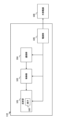
- FIG. 2 is a diagram showing the configuration of a conventional RIS according to a comparative example.
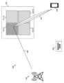
- FIG. 1 is a diagram illustrating a wireless communication system according to Embodiment 1 of the present disclosure.
- FIG. 1 is a block diagram showing a detailed configuration of a wireless communication system according to Embodiment 1 of the present disclosure.
- FIG. 4 is a diagram comparing the characteristics of reflected radio waves when (a) all of the elements included in the reflecting section of the RIS are driven, and (b) when only some of the elements are driven.
- FIG. 3 is a flowchart for determining the number of drive elements of an RIS according to Embodiment 1 of the present disclosure.
- FIG. 2 is a diagram illustrating a wireless communication system according to Embodiment 2 of the present disclosure.
- 12 is a flowchart for determining the number of drive elements of an RIS according to Embodiment 2 of the present disclosure.
- FIG. 1 is a diagram showing the configuration of a conventional RIS according to a comparative example.
- the reflecting section 101 reflects the incident radio waves.
- the reflecting section 101 has a plurality of elements 102, and shifts the phase of the incident radio wave by a necessary amount via the elements 102.
- the control unit 103 electrically controls all of the elements 102 included in the reflection unit 101 and adjusts the amount of phase change given to the radio waves.
- the communication unit 104 communicates with an external device and receives data on the amount of phase change to be given to radio waves or data necessary to calculate the amount of phase change. It also outputs the received information to the control unit 103.
- the power supply section 105 supplies power to each section of the RIS 110.
- the power supply unit 105 is connected to an external power supply 106 by wire.
- the external power supply 106 is a commercial power supply or the like.
- FIG. 2 is a diagram illustrating a wireless communication system according to Embodiment 1 of the present disclosure.
- the reflection unit 211 of the RIS 210 reflects the incident radio wave 260 that has entered from the base station 230. Further, similarly to the comparative example in FIG. 1, the reflecting section 211 has a plurality of elements 212. The reflected radio waves 270 are emitted toward the terminal device 240.
- the wireless base station (hereinafter referred to as base station) 230 is a wireless base station.
- the radio waves transmitted from the base station 230 and reaching the reflection section 211 of the RIS 210 are incident radio waves 260 .
- the wireless terminal device (hereinafter referred to as a terminal device) 240 is a mobile terminal such as a mobile phone, or a fixedly installed sensor terminal.
- the terminal device 240 receives reflected radio waves 270 emitted from the RIS 210.
- the wireless communication control device 250 performs calculations necessary to control the RIS 210 and controls the RIS 210.
- the RIS 210 is controlled by the wireless communication control device 250, and dynamically switches the reflection characteristics of the incident radio wave 260 that has entered from the wireless base station 230.
- the generated reflected radio wave 270 is emitted toward the terminal device 240.
- the wireless communication control device 250 may be placed anywhere as long as it can wirelessly communicate with the RIS 210 and the terminal device 240, and may be included within the RIS 210. Alternatively, it may be included in the wireless base station 230 or the wireless terminal 240.
- FIG. 3 is a block diagram showing a detailed configuration of a wireless communication system according to Embodiment 1 of the present disclosure.
- the wireless communication system 200 includes a RIS 210. Similar to the comparative example in FIG. 1, the RIS 210 includes a reflection section 211, a control section 220, and a communication section 221. Further, the reflecting section 211 includes an element 212.
- the control unit 220 electrically controls only the necessary number of the elements 212 included in the reflection unit 211 based on information on the number of driving elements calculated by the wireless communication control device 250.
- the control unit 220 drives only part of the element 212, the effective range 213 of the reflective surface becomes smaller than the range of the reflective unit 211, as in the example of FIG.
- the control section 220 drives all the elements 212, the effective range 213 of the reflecting surface and the range of the reflecting section 211 become equal.
- the communication unit 221 receives data such as the calculation result of the number of driving elements calculated by the wireless communication control device 250, and outputs it to the control unit 220.
- the RIS 210 of this embodiment does not have a power supply unit connected to an external power supply. Instead, it has a power generation section 223 and performs private power generation. Electric power generated by the power generation section 223 is supplied from the power supply section 222 to each section.
- the RIS 210 of this embodiment reduces power consumption by controlling the number of drive elements, it can operate without relying on external power supply. However, as in the comparative example, it may be connected to an external power supply, and the design may be made in accordance with the usage conditions of the RIS 210.
- the terminal device 240 includes a sensor section 241 and a communication section 242.
- the sensor unit 241 acquires position information of the terminal device 240 itself. Specifically, it is acquired using GPS, LiDAR, etc.
- the sensor unit 241 may measure the received power of radio waves transmitted from the base station 230. In this case, the radio waves detected by the sensor unit 241 are, for example, reflected radio waves 270 reflected from the RIS 210.
- the communication unit 242 transmits data such as position information of the terminal device 240 itself to the wireless communication control device 250.
- the wireless communication control device 250 includes an RIS control section 251 and a communication section 252.
- the RIS control unit 251 calculates the number of driving elements in the RIS 210 based on the position information of the terminal device 240 and outputs it to the communication unit 252.
- the communication unit 252 transmits information on the number of driving elements of the RIS 210 to the RIS 210.
- the wireless communication control device 250 calculates the number of driving elements in the RIS 210 based on the position information of the terminal device 240. Based on this information on the number of driven elements, the RIS 210 drives the required number of elements 212.
- FIG. 4 is a diagram comparing the characteristics of reflected radio waves when (a) all of the elements included in the RIS reflection section are driven, and (b) when only some of them are driven.
- FIG. 4(a) shows the case where all the elements are driven.
- the effective range 213 of the reflective surface is equal to the range of the reflective section 211.
- the reflection gain is large.
- reflected radio waves 270 with a narrow reflection width and excellent directivity can be generated.
- power consumption is large.
- FIG. 4(b) shows a case where only a part of the element is driven. If the effective range 213 of the reflective surface becomes extremely small by limiting the number of elements, the reflection gain will be smaller than when all the elements 212 are driven. However, even if only a part of the element 212 is driven, if a reflection area that can sufficiently reflect the incident radio wave 260 is secured, a reflection gain comparable to that obtained when all the elements are driven can be obtained. Note that the reflection width is wider than in the case where all elements are driven. In terms of power consumption, power consumption can be reduced depending on the limited number of elements 212.
- FIG. 5 shows (a) a diagram illustrating the number of driving elements of the RIS, which is suitable when the terminal device is located far from the RIS, and (b) a diagram explaining the number of driving elements of the RIS, which is suitable when the terminal device is located close to the RIS. It is a figure explaining the number of elements.
- FIG. 5(b) there is a case where the terminal device 240 operated by the user is close to the RIS 210.
- the wavefront of the reflected radio wave 270 expands as it propagates, and the effect of lowering the reception strength at the terminal device 240 is small, so there is no need to increase the reflection gain of the RIS 210 and generate the reflected radio wave 270 with a narrow reflection width. Therefore, in this case, from the viewpoint of reducing power consumption, it is preferable to drive only a part of the element 212.
- the relationship between the distance between the terminal device 240 and the RIS 210 and the number of drive elements of the RIS shown in FIGS. 5(a) and 5(b) can be said to be suitable from the viewpoint of positioning error of the terminal device.
- the radio waves may not reach the correct position of the terminal device 240 due to positioning errors.
- the distance between the RIS 210 and the terminal device 240 is long as shown in FIG. Become.
- the reflected radio wave 270 with a wide reflection width is generated by driving a part of the element, so that the influence of positioning errors can be suppressed in reception of radio waves at the terminal device 240.
- the reflected radio waves 270 received by the terminal device 240 can be received. Power consumption can be reduced while maintaining strength.
- FIG. 6 is a flowchart for determining the number of driving elements of the RIS according to Embodiment 1 of the present disclosure.
- the base station 230 is referred to as a radio wave transmission point 230
- the terminal device 240 is referred to as a reception point 240.
- the wireless communication control device 250 starts processing (step 280).
- the base station 230 and the RIS 210 are at fixed positions at the start of the process, and these positions are known.
- the position of the terminal device 240 is directly notified from the terminal device 240 to the wireless communication control device 250, or can be estimated from sensor information.
- the distance d 1 between the transmission point 230 and the RIS 210 is calculated. Furthermore, based on the position information of the terminal device 240, the distance d2 between the RIS 210 and the receiving point 240 is calculated (step 281).
- a first Fresnel radius r is calculated (step 282).
- the first Fresnel radius can be determined using the following (Equation 1).
- ⁇ is the wavelength of the incident radio wave.
- the first Fresnel radius r is a parameter determined according to two types of distances: the distance d 1 between the transmission point and the RIS 210, and the distance d 2 between the RIS 210 and the reception point, and Represents the size of the area.
- the first Fresnel radius r becomes small because the effect of spreading radio waves at the position of the RIS 210 is small.
- the base station 230 and the terminal device 240 are far from the RIS 210, the effect of spreading radio waves at the position of the RIS 210 is large, so the first Fresnel radius r becomes large.
- the reflection area S of the reflection section 211 is calculated (step 283).
- the diameter 2r of the circle determined from the first Fresnel radius r is compared with the length L of one side of the reflection section 211 (unit: m, for example). Based on the comparison results, the reflection area S is determined by the following (Equation 2).
- L ⁇ 2r means that the diameter value of the size of the radio wave area at the position of the RIS 210 is larger than the length L of one side of the reflecting section 211.
- the reflection area S is made equal to the area L2 of the reflection section 211.
- L ⁇ 2r means that the diameter value of the size of the radio wave area at the position of the RIS 210 is less than or equal to the length L of one side of the reflecting portion 211.
- the reflection area S is assumed to be equal to the area ⁇ r 2 determined from the first Fresnel radius.
- the number N of drive elements in the RIS 210 is determined from the reflection area S (step 284).
- the number N of drive elements is determined by the following (Equation 3).
- ⁇ S is the arrangement density of the elements 212 (the unit is, for example, elements/m 2 ).
- the radio communication control device 250 can generate radio waves at the position of the RIS 210 according to the distance d 1 between the transmission point and the RIS 210 and the distance d 2 between the RIS 210 and the reception point.
- the size of the area can be estimated.
- the number of driving elements of the RIS 210 can be determined based on a comparison between the diameter value of the radio wave area and the length L of one side of the reflecting section 211.
- the element 212 of the reflector 211 of the RIS 210 is Determine the number of drives. Thereby, power consumption can be reduced. By reducing power consumption, the RIS 210 can be operated to improve communication quality over a long period of time even when operating using in-house power generation such as energy harvesting instead of an external power source.
- the number N of driving elements is determined according to the distance between the base station 230 and the RIS 210 and the distance between the terminal device 240 operated by the user and the RIS 210.
- the number N of drive elements can be determined only from the distance between the terminal device 240 and the RIS 210. Note that this point is also common to Embodiment 2 below.
- the processing performed by the wireless communication control device 250 in the present disclosure may be executed by a program using a computer that includes a CPU and a memory and stores a program in the memory.
- the program may be executed using an integrated circuit such as an FPGA (Field Programmable Gate Array).
- the program may be provided recorded on a storage medium or may be provided through a network. Note that this point is also common to Embodiment 2 below.
- the RIS 210 described in this embodiment and subsequent embodiments is named a radio wave reflection device.
- the process for determining the number of drive elements described in this embodiment is named the process for determining the number of drive elements.
- the drive element number determination process is, for example, a series of processes shown in FIG.
- FIG. 6 is an example and does not limit the technical scope of the present disclosure.
- reflection area calculation process is named reflection area calculation process.
- the reflection area calculation process is, for example, the process performed in step 283.
- step 283 is an example and does not limit the technical scope of the present disclosure.
- FIG. 7 is a diagram illustrating a wireless communication system according to Embodiment 2 of the present disclosure.
- the wireless communication system 300 is the same as the first embodiment, but the RIS 210 includes a plurality of reflecting sections 211(1), 211(2), . . . , 211(4).
- the number of driving elements may be controlled by adjusting the number of reflecting sections 211 to be driven. For example, in the example of FIG. 7, only the reflecting section 211(1) is driven, and the other reflecting sections 211(2), . . . , 211(4) are not used.
- FIG. 8 is a flowchart for determining the number of RIS drive elements according to Embodiment 2 of the present disclosure.
- the wireless communication control device 250 starts processing (step 310).
- the signal-to-noise ratio (hereinafter referred to as SNR) Pr is measured for the received signal of the reflected radio wave 270 at the terminal device 240 (step 312).
- received power instead of SNR, received power, communication speed, MCS (Modulation and Coding Scheme) index, etc. may be used. These are also measured by the sensor unit 241 of the wireless terminal 240 and notified to the wireless communication control device 250.
- MCS Modulation and Coding Scheme
- step 313 it is determined whether the measured SNR P r is larger than a preset threshold P th (step 313). If the measured SNR P r is found to be larger than the threshold P th , the current number of drive reflectors 211 satisfies the specified reception power, so the number K of reflectors 211 to be driven remains unchanged. The value is maintained (step 314).
- the number N of driving elements in the RIS 210 is determined based on the driving number of the reflecting section 211 determined in step 314 (step 315).
- the number N of driving elements in the RIS 210 is determined by the following (Formula 4), where M is the number of elements 212 included in one reflecting section 211.
- the number K of the reflecting sections 211 may be output as is.
- step 316 If the process has proceeded to step 315, the process ends (step 316).
- step 313 if the SNR Pr measured in step 313 is not found to be greater than the threshold P th , it means that the specified received power has not been achieved.
- a process is performed to determine whether the number K of reflecting sections 211 currently being driven is equal to the upper limit value Kmax (step 317).
- step 319 the number N of driving elements in the RIS 210 is determined using (Equation 4) (step 319). After step 319, the process returns to step 312.
- the number K of the reflecting sections 211 may be output as is.
- step 317 if it is determined in step 317 that the number K of reflective sections 211 to be driven is equal to the upper limit value K max , all of the reflective sections 211 have already been driven. In this case, processing is further performed to determine whether SNR P r is smaller than the minimum allowable SNR value P min (step 320).
- the minimum allowable value P min is the minimum SNR at which it can be considered that the terminal device 240 has correctly received the reflected radio wave 270 from the RIS 210, and is a value that is equal to or less than the threshold value P th .
- step 320 if the SNR Pr is not found to be smaller than the minimum allowable value P min , it means that the minimum SNR has been secured in the terminal device 240. In this case, the number K of reflective sections 211 to be driven is maintained at K max (step 314).
- the wireless communication control device 250 can determine the number of drive reflectors and the number of drive elements in the RIS 210 based on the reception quality of the reflected radio waves 270 by the terminal device 240.
- the number of driving reflection units is determined based on the reception quality of the reflected radio waves 270 at the terminal device 240.
- the number of drive reflectors may be determined depending on the distance between the base station 230 and the RIS 210 and the distance between the terminal device 240 operated by the user and the RIS 210.
- the number of driving reflection parts may be determined based on at least one of the two criteria, and both criteria may be used simultaneously.
- the number of driving elements may be determined based on at least one of these two criteria.
- the number of driven elements can be controlled by adjusting the number of driven reflecting parts 211 in the RIS 210 configured from a plurality of reflecting parts 211. can. Thereby, power consumption of the RIS 210 can be reduced.
- the method of controlling the number of driven elements by adjusting the number of driven reflecting parts 211 in the RIS 210 including a plurality of reflecting parts 211 has been described.
- the number of elements to be driven may be controlled within each reflecting section 211.
- a wireless communication system including the RIS 210 that can reduce power consumption, and a wireless communication method using RIS that can reduce power consumption.
- a wireless communication control device used for controlling RIS that can reduce power consumption.
- RIS 101 Conventional RIS 101, 211 Reflection section 102, 212 Element 103, 220 Control section 104, 221 Communication section 105 Power supply section 106 External power supply 200, 300 Wireless communication system 210 RIS 213 Effective range of reflective surface 230 Base station, transmission point 240 Terminal device, reception point 241 Sensor unit 242 Communication unit 250 Wireless communication control device 251 RIS control unit 252 Communication unit 260 Incident radio wave 270 Reflected radio wave
Landscapes
- Engineering & Computer Science (AREA)
- Computer Networks & Wireless Communication (AREA)
- Signal Processing (AREA)
- Mobile Radio Communication Systems (AREA)
Abstract
Description
前記無線電波反射装置に入射する電波を発信する無線基地局と、
無線通信制御装置と、
を備え、
前記無線通信制御装置は、
前記無線端末装置の位置情報を受信する処理と、
前記無線電波反射装置により反射される反射電波の前記無線端末装置による受信品質、および前記無線電波反射装置と前記無線端末装置間の距離の、少なくとも一方に応じて、前記無線電波反射装置が駆動する駆動素子数を決定する駆動素子数決定処理と、
前記駆動素子数の情報を前記無線電波反射装置に送信する処理と、
を実行するように構成され、
前記無線電波反射装置は、前記駆動素子数の情報に基づき、前記素子を駆動する処理を実行するように構成される無線通信システムであることが望ましい。
無線通信制御装置は、
前記無線端末装置の位置情報を受信する処理と、
前記無線電波反射装置により反射される反射電波の前記無線端末装置による受信品質、および前記無線電波反射装置と前記無線端末装置間の距離の、少なくとも一方に応じて、前記無線電波反射装置が駆動する駆動素子数を決定する駆動素子数決定処理と、
前記駆動素子数の情報を前記無線電波反射装置に送信する処理と、
を実行し、
前記無線電波反射装置は、前記駆動素子数の情報に基づき、前記素子を駆動する処理を実行する無線通信方法であることが望ましい。
前記無線端末装置の位置情報を受信する処理と、
前記無線電波反射装置により反射される反射電波の前記無線端末装置による受信品質、および前記無線電波反射装置と前記無線端末装置間の距離の、少なくとも一方に応じて、前記無線電波反射装置が駆動する駆動素子数を決定する駆動素子数決定処理と、
前記駆動素子数の情報を前記無線電波反射装置に送信する処理と、
を実行するように構成される無線通信制御装置であることが望ましい。
ここではまず、比較例として従来技術について説明する。図1は比較例に係る、従来のRISの構成を示す図である。従来のRIS110において、反射部101は、入射した電波を反射する。反射部101は、複数の素子102を有し、素子102を介して入射電波の位相を必要な量だけずらす。制御部103は、反射部101が有する素子102のすべてに対して電気的な制御を行い、電波に与える位相の変化量を調整する。通信部104は外部機器と通信し、電波に与えるべき位相の変化量のデータ、または位相の変化量を算出するために必要なデータを受信する。また、受信した情報を制御部103に出力する。電源部105は、電力をRIS110の各部へ供給する。電源部105は外部電源106に有線接続される。外部電源106は商用電源等である。
図2は、本開示の実施の形態1に係る、無線通信システムを説明する図である。無線通信システム200において、RIS210の反射部211は基地局230から入射した入射電波260を反射する。また、図1の比較例と同様に、反射部211は複数の素子212を有する。反射された反射電波270は、端末装置240に向けて発せられる。



本実施形態、およびこれ以降の実施形態で説明するRIS210を、無線電波反射装置と名付ける。
図7は、本開示の実施の形態2に係る、無線通信システムを説明する図である。無線通信システム300は、実施の形態1と共通であるが、RIS210は、複数の反射部211(1)、211(2)、・・・、211(4)を備える。

101、211 反射部
102、212 素子
103、220 制御部
104、221 通信部
105 電源部
106 外部電源
200、300 無線通信システム
210 RIS
213 反射面の有効範囲
230 基地局、送信点
240 端末装置、受信点
241 センサ部
242 通信部
250 無線通信制御装置
251 RIS制御部
252 通信部
260 入射電波
270 反射電波
Claims (7)
- 反射部に複数の素子を備え、前記素子ごとに、入射電波に対して位相の変化量の調整を行い、無線端末装置に向けて前記入射電波を反射する無線電波反射装置と、
前記無線電波反射装置に入射する電波を発信する無線基地局と、
無線通信制御装置と、
を備え、
前記無線通信制御装置は、
前記無線端末装置の位置情報を受信する処理と、
前記無線電波反射装置により反射される反射電波の前記無線端末装置による受信品質、および前記無線電波反射装置と前記無線端末装置間の距離の、少なくとも一方に応じて、前記無線電波反射装置が駆動する駆動素子数を決定する駆動素子数決定処理と、
前記駆動素子数の情報を前記無線電波反射装置に送信する処理と、
を実行するように構成され、
前記無線電波反射装置は、前記駆動素子数の情報に基づき、前記素子を駆動する処理を実行するように構成される無線通信システム。 - 前記無線電波反射装置は、前記反射部を複数備え、
前記無線通信制御装置は、
前記駆動素子数決定処理においては、駆動反射部数を決定することで前記駆動素子数を決定する処理を含む、請求項1に記載の無線通信システム。 - 前記無線通信制御装置は、
前記駆動素子数決定処理においては、
前記無線基地局と前記無線電波反射装置間の距離をd1とし、前記無線電波反射装置と前記無線端末装置間の距離をd2とし、前記電波の波長をλとして、以下の式で表される第一フレネル半径rを求める処理と、
前記第一フレネル半径rから推定される、前記無線電波反射装置の位置における前記電波の領域の大きさと、前記反射部の大きさとの比較に基づき、反射面積を算出する反射面積算出処理と、
前記反射面積に基づき前記駆動素子数を決定する処理と、
を実行するように構成される請求項1または2に記載の無線通信システム。 - 前記無線通信制御装置は、
前記反射面積算出処理においては、前記無線電波反射装置の位置における前記電波の領域の大きさを2rとし、前記反射部の大きさをLとして、以下の式により前記反射面積を算出する請求項3に記載の無線通信システム。

- 前記無線通信制御装置は、
前記駆動素子数決定処理においては、前記受信品質と前記受信品質の閾値との比較に基づき、前記駆動素子数を決定する、請求項1または2に記載の無線通信システム。 - 反射部に複数の素子を備え、前記素子ごとに、無線基地局から入射する入射電波に対して位相の変化量の調整を行い、無線端末装置に向けて前記入射電波を反射する無線電波反射装置を用いた無線通信方法であって、
無線通信制御装置は、
前記無線端末装置の位置情報を受信する処理と、
前記無線電波反射装置により反射される反射電波の前記無線端末装置による受信品質、および前記無線電波反射装置と前記無線端末装置間の距離の、少なくとも一方に応じて、前記無線電波反射装置が駆動する駆動素子数を決定する駆動素子数決定処理と、
前記駆動素子数の情報を前記無線電波反射装置に送信する処理と、
を実行し、
前記無線電波反射装置は、前記駆動素子数の情報に基づき、前記素子を駆動する処理を実行する無線通信方法。 - 反射部に複数の素子を備え、前記素子ごとに、入射電波に対して位相の変化量の調整を行い、無線端末装置に向けて前記入射電波を反射する無線電波反射装置の制御に用いる無線通信制御装置であって、
前記無線端末装置の位置情報を受信する処理と、
前記無線電波反射装置により反射される反射電波の前記無線端末装置による受信品質、および前記無線電波反射装置と前記無線端末装置間の距離の、少なくとも一方に応じて、前記無線電波反射装置が駆動する駆動素子数を決定する駆動素子数決定処理と、
前記駆動素子数の情報を前記無線電波反射装置に送信する処理と、
を実行するように構成される無線通信制御装置。
Priority Applications (2)
| Application Number | Priority Date | Filing Date | Title |
|---|---|---|---|
| PCT/JP2022/028819 WO2024023937A1 (ja) | 2022-07-26 | 2022-07-26 | 無線通信システム、無線通信方法、無線通信制御装置 |
| JP2024536603A JP7816527B2 (ja) | 2022-07-26 | 2022-07-26 | 無線通信システム、無線通信方法、無線通信制御装置 |
Applications Claiming Priority (1)
| Application Number | Priority Date | Filing Date | Title |
|---|---|---|---|
| PCT/JP2022/028819 WO2024023937A1 (ja) | 2022-07-26 | 2022-07-26 | 無線通信システム、無線通信方法、無線通信制御装置 |
Publications (1)
| Publication Number | Publication Date |
|---|---|
| WO2024023937A1 true WO2024023937A1 (ja) | 2024-02-01 |
Family
ID=89705645
Family Applications (1)
| Application Number | Title | Priority Date | Filing Date |
|---|---|---|---|
| PCT/JP2022/028819 Ceased WO2024023937A1 (ja) | 2022-07-26 | 2022-07-26 | 無線通信システム、無線通信方法、無線通信制御装置 |
Country Status (2)
| Country | Link |
|---|---|
| JP (1) | JP7816527B2 (ja) |
| WO (1) | WO2024023937A1 (ja) |
Citations (2)
| Publication number | Priority date | Publication date | Assignee | Title |
|---|---|---|---|---|
| WO2021239311A1 (en) * | 2020-05-29 | 2021-12-02 | British Telecommunications Public Limited Company | Ris-assisted wireless communications |
| WO2022150118A1 (en) * | 2021-01-05 | 2022-07-14 | Google Llc | Adaptive phase-changing device power-saving operations |
-
2022
- 2022-07-26 WO PCT/JP2022/028819 patent/WO2024023937A1/ja not_active Ceased
- 2022-07-26 JP JP2024536603A patent/JP7816527B2/ja active Active
Patent Citations (2)
| Publication number | Priority date | Publication date | Assignee | Title |
|---|---|---|---|---|
| WO2021239311A1 (en) * | 2020-05-29 | 2021-12-02 | British Telecommunications Public Limited Company | Ris-assisted wireless communications |
| WO2022150118A1 (en) * | 2021-01-05 | 2022-07-14 | Google Llc | Adaptive phase-changing device power-saving operations |
Non-Patent Citations (2)
| Title |
|---|
| HU XIAOLING; ZHONG CAIJUN; ZHANG YU; CHEN XIAOMING; ZHANG ZHAOYANG: "Location Information Aided Multiple Intelligent Reflecting Surface Systems", IEEE TRANSACTIONS ON COMMUNICATIONS, IEEE SERVICE CENTER, PISCATAWAY, NJ. USA., vol. 68, no. 12, 31 August 2020 (2020-08-31), pages 7948 - 7962, XP011826106, ISSN: 0090-6778, DOI: 10.1109/TCOMM.2020.3020577 * |
| MAZLOUM NAFISEH; EDFORS OVE: "Initial Analysis of Dynamic Panel Activation for Large Intelligent Surfaces", 2021 IEEE WORKSHOP ON SIGNAL PROCESSING SYSTEMS (SIPS), IEEE, 19 October 2021 (2021-10-19), pages 18 - 22, XP034018603, DOI: 10.1109/SiPS52927.2021.00012 * |
Also Published As
| Publication number | Publication date |
|---|---|
| JP7816527B2 (ja) | 2026-02-18 |
| JPWO2024023937A1 (ja) | 2024-02-01 |
Similar Documents
| Publication | Publication Date | Title |
|---|---|---|
| JP7221186B2 (ja) | 反射方向の決定方法、中継局、および基地局 | |
| US12341574B2 (en) | Intelligent panel regulation and control method, device, and system, intelligent panel, and storage medium | |
| KR101175944B1 (ko) | 단거리 무선 모바일 통신 시스템용 지향성 최적화 | |
| TWI345392B (en) | Switched antenna transmit diversity | |
| JP2002280942A (ja) | 可変指向性アンテナを備えた情報端末装置 | |
| JP7816526B2 (ja) | 無線通信システム、無線通信方法及び無線通信制御装置 | |
| CN115765819A (zh) | 面向通信感知一体化的智能超表面的波束赋形方法和装置 | |
| US20230328663A1 (en) | Method and apparatus for determining transmit power budget for managing rf exposure of mobile devices using radar sensing | |
| JP2021090309A (ja) | 無線送電器、および無線受電器 | |
| CN112737655A (zh) | 一种基于智能反射面的通信方法、系统及装置 | |
| JP7501626B2 (ja) | ローカル無線通信システム、エリア内受信品質制御方法、制御装置、及びプログラム | |
| JP2002353867A (ja) | 可変指向性アンテナを備えた情報端末装置 | |
| JP7816527B2 (ja) | 無線通信システム、無線通信方法、無線通信制御装置 | |
| WO2020144858A1 (ja) | 光通信装置及び光通信方法 | |
| US20240429969A1 (en) | Reconfigurable intelligent surface, communication method using the reconfigurable intelligent surface, and transceiver device including the reconfigurable intelligent surface | |
| CN1808942B (zh) | 通信系统和方法 | |
| CN110808800B (zh) | 反射装置的控制方法、服务的请求方法、装置及设备 | |
| WO2024067963A1 (en) | Control of a reflective intelligent surface | |
| JP7768349B2 (ja) | 電波制御システム、制御装置、電波制御方法、及びプログラム | |
| US20240187171A1 (en) | Communication apparatus, system, and method | |
| JP7700954B2 (ja) | 電波制御システム、制御装置、電波制御方法、及びプログラム | |
| JP7801641B2 (ja) | 反射制御装置、基地局装置、通信方法、及び無線通信システム | |
| JP2006242751A (ja) | 位置測定方法およびそれを用いた位置測定装置及び位置測定システム | |
| JP2006166397A (ja) | 移動型衛星システムにおける開ループにて移動型端末の送信電力を制御する方法及びその装置 | |
| EP4543139A1 (en) | Communication apparatus and device |
Legal Events
| Date | Code | Title | Description |
|---|---|---|---|
| 121 | Ep: the epo has been informed by wipo that ep was designated in this application |
Ref document number: 22953034 Country of ref document: EP Kind code of ref document: A1 |
|
| WWE | Wipo information: entry into national phase |
Ref document number: 2024536603 Country of ref document: JP |
|
| WWE | Wipo information: entry into national phase |
Ref document number: 18995180 Country of ref document: US |
|
| NENP | Non-entry into the national phase |
Ref country code: DE |
|
| 122 | Ep: pct application non-entry in european phase |
Ref document number: 22953034 Country of ref document: EP Kind code of ref document: A1 |