WO2024023922A1 - 仮想空間画像生成方法および仮想空間画像生成システム - Google Patents
仮想空間画像生成方法および仮想空間画像生成システム Download PDFInfo
- Publication number
- WO2024023922A1 WO2024023922A1 PCT/JP2022/028751 JP2022028751W WO2024023922A1 WO 2024023922 A1 WO2024023922 A1 WO 2024023922A1 JP 2022028751 W JP2022028751 W JP 2022028751W WO 2024023922 A1 WO2024023922 A1 WO 2024023922A1
- Authority
- WO
- WIPO (PCT)
- Prior art keywords
- image
- virtual
- virtual space
- display device
- display
- Prior art date
- Legal status (The legal status is an assumption and is not a legal conclusion. Google has not performed a legal analysis and makes no representation as to the accuracy of the status listed.)
- Ceased
Links
Images







Classifications
-
- G—PHYSICS
- G06—COMPUTING OR CALCULATING; COUNTING
- G06F—ELECTRIC DIGITAL DATA PROCESSING
- G06F3/00—Input arrangements for transferring data to be processed into a form capable of being handled by the computer; Output arrangements for transferring data from processing unit to output unit, e.g. interface arrangements
- G06F3/01—Input arrangements or combined input and output arrangements for interaction between user and computer
Definitions
- the present disclosure relates to a virtual space image generation method and a virtual space image generation system.
- VR virtual reality
- MR mixed reality
- AR augmented reality
- the wearable terminal device has a display unit that covers the user's field of vision when the wearable terminal device is worn by the user.
- a visual effect as if these exist is realized (for example, US Patent Application Publication No. 2019 /0087021 and US Patent Application Publication No. 2019/0340822).
- MR is a technology that allows users to experience mixed reality, which is a fusion of real space and virtual images, by displaying a virtual image that appears to exist at a predetermined position in the real space while allowing the user to see the real space.
- VR is a technology that allows the user to experience as if they are in the virtual space (virtual reality experience) by allowing the user to view a virtual space instead of the real space in MR.
- Patent Document 1 if an object included in a real space image captured in the real space near the user is, for example, a notebook PC, the screen of the notebook PC is also included in the real space image. If so, a virtual space image including that screen will be generated. In this case, there is a problem in that the screen of the notebook PC in the virtual space image becomes unclear depending on the imaging direction when the real space is imaged, the distance to the notebook PC, the imaging specifications, etc. Furthermore, in the technology disclosed in Patent Document 1, the screen of the notebook PC is only included in the virtual space image, and it is not possible to perform operations on the screen of the notebook PC in the virtual space image. There was a difference between virtual space and virtual space.
- the virtual space image generation method and virtual space image generation system of the present disclosure have been made in view of the above-mentioned problems, and aim to generate a virtual space image that allows the user to experience a more realistic virtual space. shall be.
- a virtual space image generation method includes: Identify display devices that exist in real space, Obtaining image data that can be displayed by the identified display device from the display device or storage in which the data is stored; A virtual space image including a virtual display image corresponding to an image that can be displayed by the display device is generated based on the acquired data of the image.
- a virtual space image generation system includes: Identify display devices that exist in real space, Obtaining image data that can be displayed by the identified display device from the display device or storage in which the data is stored; A virtual space image including a virtual display image corresponding to an image that can be displayed by the display device is generated based on the acquired data of the image.
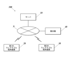
- FIG. 1 is a diagram showing a schematic configuration of a virtual space image generation system.
- FIG. 2 is a block diagram showing the functional configuration of a server.
- FIG. 2 is a block diagram showing the functional configuration of a first wearable terminal device.
- FIG. 3 is a block diagram showing the functional configuration of a second wearable terminal device.
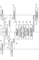
- FIG. 7 is a sequence diagram showing the operation of the virtual space image generation system in a case where a virtual space image including a virtual image of the multifunction device generated by the server is displayed on the display unit of the second wearable terminal device.
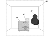
- FIG. 3 is a diagram illustrating a real space as viewed through a visor by a user wearing the first wearable terminal device. It is a figure showing an example of a virtual space image.
- FIG. 1 is a diagram showing a schematic configuration of a virtual space image generation system.
- FIG. 2 is a block diagram showing the functional configuration of a server.
- FIG. 2 is a block diagram showing the functional configuration of a first
- FIG. 2 is a diagram illustrating an example of a virtual space image including a virtual image (virtual image of a multifunction device) obtained by combining virtual display screens.
- FIG. 3 is a diagram illustrating an example of a virtual space image including a virtual image (virtual image of a multifunction peripheral) displaying a balloon screen that is an alternative to a virtual display screen.
- the operation of the virtual space image generation system in a case where the virtual image of the multifunction device displayed on the display section of the second wearable terminal device is updated and displayed in response to a screen operation performed on the display section of the multifunction device is shown. It is a sequence diagram.
- FIG. 3 is a diagram illustrating a real space as viewed through a visor by a user wearing the first wearable terminal device.
- FIG. 2 is a diagram illustrating an example of a virtual space image including a virtual image (virtual image of a multifunction device) obtained by combining virtual display screens.
- Virtual space from when an operation (user operation) is performed on the virtual display screen of the virtual image (virtual image of the multifunction peripheral) displayed on the display unit of the second wearable terminal device until the virtual image is updated and displayed.
- FIG. 2 is a sequence diagram showing the operation of the image generation system.
- FIG. 3 is a diagram illustrating a real space as viewed through a visor by a user wearing the first wearable terminal device.
- FIG. 2 is a diagram illustrating an example of a virtual space image including a virtual image (virtual image of a multifunction device) obtained by combining virtual display screens.
- FIG. 2 is a sequence diagram showing the operation of the virtual space image generation system in a case where the multifunction peripheral is moved from its original installation location to another location.
- FIG. 7 is a diagram illustrating an example of a virtual space image including a virtual image (virtual image of the multifunction device) whose display mode is changed as the multifunction device moves.
- FIG. 3 is a diagram showing an example of a virtual space image including destination information and question information.
- FIG. 3 is a diagram illustrating an example of a virtual space image corresponding to a destination of a multifunction device.
- FIG. 2 is a sequence diagram showing the operation of the virtual space image generation system in FIG.
- FIG. 3 is a diagram illustrating an example of a virtual space image including a virtual image (virtual image of a multifunction device) in a mode of outputting a virtual recording medium.
- FIG. 3 is a diagram illustrating an example of a virtual space image including a virtual image (virtual image of a multifunction device) in a mode of outputting a virtual recording medium.
- FIG. 1 is a diagram showing a schematic configuration of a virtual space image generation system 100.
- the virtual space image generation system 100 includes a server 10, a first wearable terminal device 20, a second wearable terminal device 30, and a multifunction peripheral 40 as a display device. has been done.
- the server 10 is connected to each of the first wearable terminal device 20, the second wearable terminal device 30, and the multifunction device 40 via the communication network N so as to be able to communicate information.
- the server 10 is, for example, a server on a cloud, and provides a virtual image and/or virtual space to a user wearing the first wearable terminal device 20 via the first wearable terminal device 20.
- the second wearable terminal device 30 is provided to the user wearing the second wearable terminal device 30.
- the first wearable terminal device 20 is an HMD (Head Mount Display) that is worn on the user's head. Specifically, the first wearable terminal device 20 is a so-called AR/MR goggle that provides AR or MR to the user.
- HMD Head Mount Display
- AR/MR goggle that provides AR or MR to the user.
- the second wearable terminal device 30, like the first wearable terminal device 20, is an HMD that is worn on the user's head.
- the second wearable terminal device 30 is a so-called VR goggle that provides VR to the user.
- the multifunction device 40 is a multifunction device that can be used by at least the user of the first wearable terminal device 20 (user A). It is assumed that the multifunction device 40 is installed in a predetermined area (for example, area 1). Note that the virtual space image generation system 100 may be configured to include a display device such as a PC or an electronic whiteboard in addition to the multifunction device 40.
- the communication network N is assumed to be, for example, the Internet, but may be another network such as a LAN (Local Area Network).
- LAN Local Area Network
- FIG. 2 is a block diagram showing the functional configuration of the server 10.
- the server 10 includes a CPU (Central Processing Unit) 11, a RAM (Random Access Memory) 12, a storage section 13, a communication section 14, and a bus 15. Each part of the server 10 is connected via a bus 15.
- CPU Central Processing Unit
- RAM Random Access Memory
- the CPU 11 is a processor that performs various calculation processes and centrally controls the operation of each part of the server 10.
- the CPU 11 performs various control operations by reading and executing a program 131 stored in the storage unit 13. Note that although a single CPU 11 is illustrated in FIG. 2, the present invention is not limited to this. Two or more processors such as a CPU may be provided, and the processing executed by the CPU 11 of this embodiment may be shared and executed by these two or more processors.
- the RAM 12 provides a working memory space for the CPU 11 and stores temporary data.
- the storage unit 13 is a non-temporary recording medium that can be read by the CPU 11.
- the storage unit 13 stores a program 131 executed by the CPU 11, various setting data, and the like.
- the program 131 is stored in the storage unit 13 in the form of a computer-readable program code.
- a nonvolatile storage device such as an SSD with flash memory or a hard disk drive (HDD) is used, for example.
- the data stored in the storage unit 13 includes virtual space template data used when generating a virtual space image corresponding to each area, and virtual images to be displayed in the virtual space image (for example, a virtual image of the multifunction device 40). 70), etc.
- the communication unit 14 is composed of a network card and the like.
- the communication unit 14 is communicatively connected to the communication network N, and performs communication with the first wearable terminal device 20, the second wearable terminal device 30, and the multifunction device 40 on the communication network N.
- FIG. 3 is a block diagram showing the functional configuration of the first wearable terminal device 20. As shown in FIG. 3
- the first wearable terminal device 20 includes a CPU 21, a RAM 22, a storage section 23, a display section 24, a sensor section 25, a communication section 26, etc., and each of these sections is connected to a bus 27. connected by.
- the CPU 21 is a processor that performs various calculation processes and centrally controls the operation of each part of the first wearable terminal device 20.
- the CPU 21 performs various control operations by reading and executing a program 231 stored in the storage unit 23.
- CPU 21 any processors such as a CPU may be provided, and the processing executed by the CPU 21 of this embodiment may be shared and executed by these two or more processors.
- the RAM 22 provides a working memory space for the CPU 21 and stores temporary data.
- the storage unit 23 is a non-temporary recording medium that can be read by the CPU 21.
- the storage unit 23 stores a program 231 executed by the CPU 21, various setting data, and the like.
- the program 231 is stored in the storage unit 23 in the form of a computer-readable program code.
- a nonvolatile storage device such as an SSD (Solid State Drive) equipped with a flash memory is used, for example.
- the data stored in the storage unit 23 includes avatar data 232 and the like.
- the display unit 24 includes a visor 241, a laser scanner 242, and an optical system that guides the light output from the laser scanner 242 to the display surface of the visor 241.
- the visor 241 has light transparency.
- the user can view the real space through the visor 241.
- An image such as a virtual image is projected from a laser scanner 242 and displayed on a display surface of the visor 241 that faces the user's eyes.
- the user views the virtual image using reflected light from the display surface.
- a visual effect as if the virtual image exists in the real space can be obtained.
- the laser scanner 242 scans in a predetermined direction and irradiates the optical system with pulsed laser light whose on/off is controlled for each pixel according to a control signal from the CPU 21.
- the laser light incident on the optical system forms a display screen consisting of a two-dimensional pixel matrix on the display surface of the visor 241.
- the method of the laser scanner 242 is not particularly limited, for example, a method may be used in which a mirror is operated using MEMS (Micro Electro Mechanical Systems) to scan laser light.
- MEMS Micro Electro Mechanical Systems
- the laser scanner 242 has three light emitting parts that emit laser light of RGB colors, for example.
- the display unit 24 can perform color display by projecting light from these light emitting units onto the visor 241.
- the sensor section 25 includes an acceleration sensor 251, an angular velocity sensor 252, a depth sensor 253, a camera 254, an eye tracker 255, and the like. Note that the sensor section 25 may further include a sensor not shown in FIG. 3.
- the acceleration sensor 251 detects acceleration and outputs the detection result to the CPU 21. From the detection result by the acceleration sensor 251, the translational movement of the first wearable terminal device 20 in the three orthogonal axes directions can be detected.
- the angular velocity sensor 252 detects angular velocity and outputs the detection result to the CPU 21. From the detection result by the angular velocity sensor 252, the rotational movement of the first wearable terminal device 20 can be detected.
- the depth sensor 253 is an infrared camera that detects the distance to the subject using the ToF (Time of Flight) method, and outputs the distance detection result to the CPU 21.
- the depth sensor 253 is provided on the front surface of the first wearable terminal device 20 so as to be able to photograph the user's visible area.
- the camera 254 photographs the real space RS using a group of RGB image sensors, acquires color image data as a photographed result, and outputs it to the CPU 21.
- the camera 254 is provided on the front of the first wearable terminal device 20 so as to be able to photograph the user's visible area.
- the output image from the camera 254 is used to detect the position and orientation of the first wearable terminal device 20, and is also transmitted from the communication unit 26 to an external device to display the visible area of the user of the first wearable terminal device 20. It is also used to display on external devices.
- the eye tracker 255 detects the user's line of sight and outputs the detection result to the CPU 21.
- the method of detecting the line of sight is not particularly limited, but for example, the point of reflection of near-infrared light in the user's eye is photographed with an eye tracking camera, and the photographing result and the image taken by the camera 254 are analyzed to detect the user's line of sight.
- a method can be used to identify the object that the person is viewing.
- the communication unit 26 is a communication module that includes an antenna, a modulation/demodulation circuit, a signal processing circuit, and the like.
- the communication unit 26 transmits and receives data by wireless communication to and from an external device according to a predetermined communication protocol.
- FIG. 4 is a block diagram showing the functional configuration of the second wearable terminal device 30.
- the second wearable terminal device 30 includes a CPU 31, a RAM 32, a storage section 33, a display section 34, a sensor section 35, a communication section 36, etc., and each of these sections is connected to a bus 37. connected by.
- the CPU 31 is a processor that performs various calculation processes and centrally controls the operation of each part of the second wearable terminal device 30.
- the CPU 31 performs various control operations by reading and executing a program 331 stored in the storage unit 33.
- CPU 31 any processors such as a CPU may be provided, and the processing executed by the CPU 31 of this embodiment may be shared and executed by these two or more processors.
- the RAM 32 provides a working memory space for the CPU 31 and stores temporary data.
- the storage unit 33 is a non-temporary recording medium that can be read by the CPU 31.
- the storage unit 33 stores a program 331 executed by the CPU 31, various setting data, and the like.
- the program 331 is stored in the storage unit 33 in the form of a computer-readable program code.
- a nonvolatile storage device such as an SSD equipped with a flash memory is used, for example.
- the data stored in the storage unit 33 includes avatar data 332 and the like.
- the display section 34 includes a left eye display section 341 and a right eye display section 342.
- the virtual space image 50 which is a VR image
- the left eye image of the virtual space image 50 is displayed on the left eye display unit 341
- the right eye image of the virtual space image 50 is displayed on the left eye display unit 341.
- the sensor section 35 includes an acceleration sensor 351, an angular velocity sensor 352, a camera 353, an eye tracker 354, and the like. Note that the sensor section 35 may further include a sensor not shown in FIG. 4.
- the acceleration sensor 351 detects acceleration and outputs the detection result to the CPU 31. From the detection result by the acceleration sensor 351, the translational movement of the second wearable terminal device 30 in the three orthogonal axes directions can be detected.
- the angular velocity sensor 352 detects angular velocity and outputs the detection result to the CPU 31. From the detection result by the angular velocity sensor 352, the rotational movement of the second wearable terminal device 30 can be detected.
- the camera 353 photographs the real space RS using a group of RGB image sensors, acquires color image data as a photographed result, and outputs it to the CPU 31.
- the camera 353 is provided on the front of the second wearable terminal device 30 so as to be able to photograph the user's visible area.
- the output image from the camera 353 is used to detect the position and orientation of the second wearable terminal device 30, and is also transmitted from the communication unit 36 to an external device to detect the visible area of the user of the second wearable terminal device 30. It is also used to display on external devices.
- the eye tracker 354 detects the user's line of sight and outputs the detection result to the CPU 31.
- the line of sight detection method is not particularly limited, but for example, the near-infrared light reflection point in the user's eye is photographed with an eye tracking camera, and the photographed result and the image taken by the camera 353 are analyzed to detect the user's line of sight.
- a method can be used to identify the object that the person is viewing.
- the communication unit 36 is a communication module that includes an antenna, a modulation/demodulation circuit, a signal processing circuit, and the like.
- the communication unit 36 transmits and receives data by wireless communication to and from an external device according to a predetermined communication protocol.
- FIG. 5 shows the operation of the virtual space image generation system 100 in a case where a virtual space image 50 including a virtual image 70 of the multifunction peripheral 40 generated by the server 10 is displayed on the display section 34 of the second wearable terminal device 30.
- FIG. 5 shows the operation of the virtual space image generation system 100 in a case where a virtual space image 50 including a virtual image 70 of the multifunction peripheral 40 generated by the server 10 is displayed on the display section 34 of the second wearable terminal device 30.
- the server 10 acquires the avatar data 232 from the first wearable terminal device 20 (step S1). Subsequently, the server 10 acquires avatar data 332 from the second wearable terminal device 30 (step S2).
- the avatar data 232 is data for displaying the avatar A1 (avatar image) designated by the user A wearing the first wearable terminal device 20.
- the avatar data 332 is data for displaying the avatar B1 (avatar image) specified by the user B who is wearing the second wearable terminal device 30.
- the server 10 creates a virtual space shared by avatar A1, which is user A's alter ego, and avatar B1, which is user B's alter ego, based on predetermined virtual space template data, avatar data 232, and avatar data 332.
- a spatial image (for example, a virtual spatial image 50 corresponding to the area (area 1) where the multifunction device 40 is installed) is generated (step S3).
- the server 10 transmits the avatar image of the avatar B1, which is the alter ego of the user B, to the first wearable terminal device 20 (step S4).
- the first wearable terminal device 20 projects the avatar image (avatar B1) received from the server 10 onto the visor 241 and displays it.
- FIG. 6 shows the real space RS as viewed through the visor 241 by the user A wearing the first wearable terminal device 20.
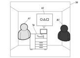
- This real space RS is a space in the area (area 1) where the multifunction device 40 is installed, and as shown in FIG. Avatar B1 is visually recognized as augmented reality.
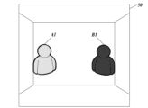
- the server 10 transmits the virtual space image 50 generated in step S3 to the second wearable terminal device 30 (step S6). Then, the second wearable terminal device 30 displays the virtual space image 50 received from the server 10 on the display unit 34, as shown in FIG. 7 (step S7).
- the first wearable terminal device 20 transmits the captured image to the server 10 (step S8).
- the server 10 identifies the multifunction device 40 based on the captured image received from the first wearable terminal device 20 (step S9).
- the multifunction device 40 is identified by analyzing the captured image. For example, the two-dimensional code of the multifunction device 40 read by the camera 254 of the first wearable terminal device 20 is The multifunction device 40 may be identified by receiving the information from the wearable terminal device 20 . Further, the multifunction device 40 may be identified by the ID of the multifunction device 40 input from the first wearable terminal device 20.
- the server 10 may be identified from the area that is the basis of the virtual space template data used when the virtual space image 50 is generated.
- the server 10 acquires predetermined screen data from the multifunction device 40 identified in step S9 (step S10). Specifically, the server 10 acquires the screen data of the screen currently displayed on the display unit 41 of the multifunction device 40 (for example, the screen on which ⁇ is displayed; see FIG. 6). For example, the server 10 may communicate directly with the multifunction device 40 or indirectly communicate with the multifunction device 40 via the first wearable device 20 to acquire predetermined image data from the multifunction device 40. Note that when the display section 41 of the multifunction device 40 is in a non-display state, screen data such as an initial screen displayed on the display section 41 of the multifunction device 40 may be acquired, for example.
- the target screen data is not limited to the case where it is acquired from the multifunction device 40 identified in step S9, but is also provided by an external server ( (not shown).
- the server 10 may acquire screen data from the external server based on transmitting the identification information of the multifunction peripheral 40 acquired in step S9 to the external server.
- the server 10 generates a virtual display screen based on the screen data acquired in step S10 (step S11). Specifically, when the server 10 acquires screen data of a screen on which ⁇ is displayed, the server 10 generates a virtual display screen 60 related to the screen on which this ⁇ is displayed.
- the server 10 generates a virtual image 70 of the multifunction peripheral 40 identified in step S9 (step S12). Specifically, the server 10 generates the virtual image 70 of the multifunction device 40 identified in step S9 based on the virtual image data stored in the storage unit 13. Further, the server 10 may generate the virtual image 70 based on the captured image of the multifunction peripheral 40 received from the first wearable terminal device 20 in step S8. Alternatively, the server 10 may communicate with the multifunction device 40 and receive data for generating the virtual image 70 from the multifunction device 40.
- the server 10 combines the virtual display screen 60 generated in step S11 with the display section of the virtual image 70 of the multifunction peripheral 40 generated in step S12 (step S13). Subsequently, the server 10 transmits the virtual image 70 obtained by combining the virtual display screen 60 to the second wearable terminal device 30 (step S14).
- the second wearable terminal device 30 converts a virtual image 70 (virtual image 70 of the multifunction device 40) into which the virtual display screen 60 is synthesized into a virtual space image displayed on the display unit 34. 50 (step S15).
- a virtual image 70 virtual image 70 of the multifunction device 40
- the virtual display screen 60 is synthesized into a virtual space image displayed on the display unit 34. 50 (step S15).
- the display on the virtual display screen 60 see FIG. 8) and the display on the balloon screen 61 (see FIG. 9) are changed. It may be possible to switch to either one.
- the second wearable terminal device 30 displays the virtual image 70 of the multifunction device 40, it displays the virtual image 70 that is a composite of the virtual display screen 60 corresponding to the screen displayed on the display unit 41 of the multifunction device 40. By displaying this, it becomes possible for the user to experience a more realistic virtual space.
- FIG. 10 shows a case where the virtual image 70 of the multifunction device 40 displayed on the display section 34 of the second wearable terminal device 30 is updated and displayed in response to a screen operation performed on the display section 41 of the multifunction device 40.
- FIG. 2 is a sequence diagram showing the operation of the virtual space image generation system 100 in FIG.
- the multifunction device 40 determines whether or not a screen operation has been performed on the display unit 41 (step S21).
- step S21 If it is determined in step S21 that no screen operation has been performed on the display unit 41 (step S21; NO), the multifunction device 40 performs the determination process in step S21 until it is determined that the screen operation has been performed. Repeat.
- step S21 if it is determined in step S21 that a screen operation has been performed on the display unit 41 (step S21; YES), the multifunction device 40 sends the screen data of the screen changed based on the screen operation to the server 10. Transmit (step S22). For example, as shown in FIG. 11, when the screen is changed to a screen where ⁇ is displayed by the screen operation of the display unit 41, the multifunction device 40 changes the screen data of the screen where ⁇ is displayed. Send to server 10. The multifunction device 40 then returns the process to step S21 and repeats the subsequent processes.
- the server 10 acquires the screen data of the changed screen from the multifunction device 40 (step S23).
- the multifunction peripheral 40 transmits information that allows identification of the screen after being changed based on the screen operation to the server 10, and However, based on the information, the corresponding screen data may be acquired from the above-mentioned external server (not shown). Further, if it is determined in step S21 that a screen operation on the display unit 41 has been performed, the multifunction peripheral 40 transmits information related to the screen operation to the server 10, and the server 10 generates screen data corresponding to the information. It may also be acquired from the storage unit 13. In such a case, it is assumed that the storage unit 13 stores in advance UI data in which information related to the screen operation of the multifunction device 40 and screen data of the screen changed by the screen operation are linked.
- the server 10 generates a virtual display screen based on the screen data acquired in step S23 (step S24). Specifically, when the server 10 acquires screen data of a screen on which ⁇ is displayed as screen data after change, the server 10 changes the virtual display screen 62 related to the screen on which ⁇ is displayed. generate.
- the server 10 combines the virtual display screen 62 generated in step S24 with the display section of the virtual image 70 of the multifunction device 40 (step S25). Subsequently, the server 10 transmits the virtual image 70 obtained by combining the virtual display screen 62 to the second wearable terminal device 30 (step S26).
- the second wearable terminal device 30 generates a virtual image 70 (virtual image of the multifunction device 40) in which the virtual display screen 62 is combined with the virtual space image 50 already displayed on the display unit 34. 70) is updated and displayed (step S27).
- the virtual image 70 of the multifunction device 40 displayed on the display unit 34 of the second wearable terminal device 30 is changed in accordance with the screen operation. is updated and displayed, allowing the user to experience an even more realistic virtual space.
- FIG. 13 shows a virtual display screen (for example, virtual display screen 62; see FIG. 12) of a virtual image 70 (virtual image 70 of the multifunction peripheral 40) displayed on the display unit 34 of the second wearable terminal device 30.
- FIG. 3 is a sequence diagram showing the operation of the virtual space image generation system 100 from when a user operation is performed to when the virtual image 70 is updated and displayed.
- the second wearable terminal device 30 displays a virtual display screen (for example, a virtual display screen 62; (see FIG. 12) is accepted (step S31).
- a virtual display screen for example, a virtual display screen 62; (see FIG. 12) is accepted (step S31).
- the second wearable terminal device 30 transmits the virtual display screen operation information received in step S31 to the server 10 (step S32). Subsequently, the server 10 transmits the virtual display screen operation information acquired from the second wearable terminal device 30 to the multifunction device 40 (step S33).
- the multifunction peripheral 40 updates and displays the screen of the display unit 41 based on the operation information of the virtual display screen acquired from the server 10 (step S34). For example, in the virtual display screen 62 (see FIG. 12) where the virtual display screen operation information obtained from the server 10 displays ⁇ , an operation to change the display of ⁇ to the display of ⁇ information, the multifunction device 40 updates the screen of the display unit 41 from a state in which ⁇ is displayed to a state in which ⁇ is displayed, as shown in FIG. 14, based on the operation information. . Note that when the operation information on the virtual display screen acquired from the server 10 is operation information for causing the multifunction device 40 to perform a predetermined operation, the multifunction device 40 executes the operation corresponding to the operation information.
- the multifunction device 40 transmits the screen data of the updated (changed) screen to the server 10 (step S35). For example, as shown in FIG. 14, when the display unit 41 is updated to the ⁇ screen, the multifunction peripheral 40 transmits the screen data of the ⁇ screen to the server 10.
- the server 10 acquires the screen data of the updated (changed) screen from the multifunction device 40 (step S36). Note that if the server 10 stores in the storage unit 13 UI data in which the operation information of the virtual display screen and the screen data of the updated screen corresponding to the operation information are linked, the server 10 Based on the operation information of the virtual display screen acquired from the second wearable terminal device 30, the screen data of the corresponding updated screen may be acquired from the storage unit 13.
- the server 10 generates a virtual display screen based on the screen data acquired in step S36 (step S37). Specifically, when the server 10 acquires screen data of a screen on which ⁇ is displayed as updated (post-changed) screen data, the server 10 acquires the virtual screen data related to the screen on which ⁇ is displayed. A display screen 63 is generated.
- the server 10 combines the virtual display screen 63 generated in step S37 with the display section of the virtual image 70 of the multifunction device 40 (step S38). Subsequently, the server 10 transmits the virtual image 70 obtained by combining the virtual display screen 63 to the second wearable terminal device 30 (step S39).
- the second wearable terminal device 30 generates a virtual image 70 (virtual image of the multifunction device 40) in which the virtual display screen 63 is combined with the virtual space image 50 already displayed on the display unit 34. 70) is updated and displayed (step S40).
- the number of second wearable terminal devices 30 is one, but it may be two or more.
- the virtual image 70 is displayed on the display unit 34 of the second wearable terminal device 30 under the control of the server 10. For each virtual image 70, it may be possible to set whether or not to include a virtual display screen or a balloon screen. Further, for each second wearable terminal device 30, it may be possible to set whether or not to permit operations on the virtual display screen or the balloon screen.
- FIG. 16 is a sequence diagram showing the operation of the virtual space image generation system 100 in a case where the multifunction device 40 moves from a predetermined installation location (for example, area 1) to another location (for example, area 2).
- a predetermined installation location for example, area 1
- another location for example, area 2.
- the multifunction device 40 periodically transmits its most recent position information to the server 10 (step S31).
- This location information is, for example, a beacon ID received from a beacon transmitter (not shown) installed in a predetermined area (for example, area 1, area 2, etc.); It may be an identification number received from a WiFi (registered trademark)-AP (access point) installed in the area, self-location information estimated using SLAM (Simultaneous Localization and Mapping) technology, location information based on GNSS positioning, etc.
- the multifunction device 40 determines whether or not the device is outside area 1, which is the initial installation location, based on the above location information, and transmits the result of the determination to the server 10. Good too.
- the multifunction device 40 has map information that allows its current location to be specified based on the above location information, and information that indicates the initial installation location. Further, the first wearable terminal device 20 worn by the user A determines whether the multifunction device 40 is outside the area 1 based on the captured image captured by the camera 254 of the own device, The result of the determination may be sent to the server 10.
- the server 10 determines whether the multifunction device 40 is outside area 1, which is the predetermined installation location, based on the above position information acquired from the multifunction device 40 (step S42).
- the server 10 stores in the storage unit 13 map information that allows the current location to be specified based on the above location information, and information indicating the original installation location of the multifunction device 40.
- the area 1 where the multifunction device 40 is installed is not limited to the entire space of a certain room, but may be a part of the room.
- step S42 if it is determined that the multifunction device 40 is not outside area 1, which is the predetermined installation location, that is, it is within area 1 (step S42; NO), the server 10 receives the information transmitted from the multifunction device 40. Wait for location information to be acquired.
- step S42 determines that the multifunction device 40 is outside area 1, which is the predetermined installation location (step S42; YES)
- the server 10 displays the virtual image 71 whose display mode has been changed in the second It is transmitted to the wearable terminal device 30 (step S43).
- the second wearable terminal device 30 displays (updates and displays) the virtual image 71 acquired from the server 10 on the virtual space image 50 (step S44).
- the virtual space image 50 is a virtual space image corresponding to area 1, which is a predetermined installation location of the multifunction device 40.
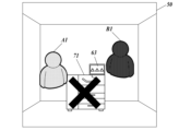
- an image in which an x mark is superimposed on the virtual image of the multifunction device 40 is used as a virtual image 71 with a changed display mode.
- characters, symbols, etc. may be used as the virtual image 71 with a changed display mode.
- the display mode may be changed by changing the display color of the virtual image of the multifunction device 40, by displaying the virtual image blinking, or by causing the virtual image to move (for example, swing from side to side). It may also be a virtual image 71. Further, when displaying the virtual image 71 with a changed display mode, the virtual display screen (for example, the virtual display screen 63; see FIG. 17) may be hidden. Further, when it is determined that the multifunction device 40 is outside area 1, the server 10 hides the virtual image 70 of the multifunction device 40 displayed on the display unit 34 of the second wearable terminal device 30. Display control may be performed to change the display to .
- the server 10 transmits destination information I1 indicating the destination of the multifunction peripheral 40 and inquiry information I2 asking whether the user will move to the destination, to the second wearable terminal device 30 ( Step S45).
- the second wearable terminal device 30 displays the destination information I1 and inquiry information I2 acquired from the server 10 on the virtual space image 50, as shown in FIG.
- the inquiry information I2 is in a screen format, and the screen includes a YES button I21 for instructing to move to the destination, and a NO button I22 for instructing not to move to the destination. It is set in.
- the second wearable terminal device 30 determines whether a user operation (operation of the YES button I21) instructing to move to a destination has been performed (step S47).
- step S47 if it is determined that the user operation (operation of the YES button I21) instructing to move to the destination has not been performed (step S47; NO), the second wearable terminal device 30 continues to display the virtual space image 50 corresponding to Area 1, which is the predetermined installation location.
- step S47 if it is determined in step S47 that a user operation (operation of YES button I21) instructing to move to the destination has been performed (step S47; YES), the second wearable terminal device 30 moves to the destination. Movement instruction information instructing movement is transmitted to the server 10 (step S48).
- the server 10 upon acquiring the above movement instruction information from the second wearable terminal device 30, the server 10 generates a virtual space image of the movement destination (virtual space image 51 corresponding to area 2) (step S49). ).
- the server 10 transmits the virtual space image (virtual space image 51 corresponding to area 2) generated in step S49 to the second wearable terminal device 30 (step S50). Then, as shown in FIG. 19, the second wearable terminal device 30 displays (updates display) the virtual space image (virtual space image 51 corresponding to area 2) received from the server 10 on the display unit 34 (step S51). At this time, the display unit 34 of the second wearable terminal device 30 displays the virtual image 70 in the original state (virtual image 70 of the multifunction device 40), and also indicates that the virtual image 70 has moved to the destination (area 2). Movement completion information I3 is displayed.
- the multifunction device 40 moves from a predetermined installation location (for example, area 1) to another location (for example, area 2), the corresponding
- a predetermined installation location for example, area 1
- another location for example, area 2
- the corresponding By changing the display mode of the virtual image 70 of the multifunction device 40, the user can be made aware that the multifunction device 40 has moved, so it is possible to provide a virtual space that is strongly connected to the real space.
- FIG. 20 shows a virtual image 70 (virtual image 70 of the multifunction device 40) in which a virtual recording medium 80 corresponding to the recording medium (paper; hard medium) to be actually printed is output as the multifunction device 40 performs a printing operation. ) on the display unit 34 of the second wearable terminal device 30.
- the multifunction device 40 determines whether a print instruction operation has been performed on the multifunction device 40 (step S61).
- step S61 if it is determined that the print instruction operation has not been performed on the own machine (step S61; NO), the multifunction device 40 continues to perform the determination in step S61 until it is determined that the print instruction operation has been performed. Repeat the process.
- step S61 if it is determined that a print instruction operation has been performed on the multifunction device 40 (step S61; YES), the multifunction device 40 transmits print job data to the server 10 (step S62). The multifunction device 40 then returns the process to step S61 and repeats the subsequent processes.
- the print job data includes software data to be recorded on a recording medium and hard copy information indicating that the software data is to be recorded.
- Hard copy information includes information indicating the execution of hard copy (trigger information), information related to the type of hard copy (e.g. 2D printing), and unique information of the recording medium (hard medium) (e.g. paper type, size, color, (design, etc.), specific information regarding the display means on the recording medium (for example, ink type, color, etc.), etc.
- the server 10 acquires print job data from the multifunction device 40 (step S63). Subsequently, the server 10 generates a virtual recording medium 80 corresponding to the recording medium to be actually printed by the multifunction peripheral 40 based on the acquired print job data (step S64). Subsequently, the server 10 transmits the generated virtual recording medium 80 to the second wearable terminal device 30 (step S65).
- the second wearable terminal device 30 generates a virtual image 70 (virtual image of the multifunction peripheral 40) in a mode in which the virtual recording medium 80 is output, as shown in FIG. 70) is displayed (step S66). Specifically, a virtual image 70 in which the virtual recording medium 80 is gradually ejected to the paper ejection tray is displayed. After the virtual recording medium 80 is ejected, for example, when a user operation to specify the virtual recording medium 80 is performed, a virtual recording medium 81 whose output contents can be visually confirmed is displayed as shown in FIG. It has become.
- the virtual image 70 in the form of outputting the virtual recording medium 80 (virtual image 70 of the multifunction device 40), it is not necessarily necessary to realistically reproduce the process in which the multifunction device 40 outputs the recording medium.
- the virtual image 70 (virtual image 70 of the multifunction device 40) that outputs the virtual recording medium 80 in a deformed form may be displayed.
- the virtual recording medium 80 after the output is completed may be managed independently from the virtual image 70 of the multifunction device 40.
- the avatar B1 which is the alter ego of the user B, may be able to carry around the virtual recording medium 80 and move to another virtual space (for example, the virtual space image 51).
- the virtual recording medium 80 may be edited (for example, adding characters, adding images, discarding, etc.) using the avatar B1. Further, the operations that user B can perform on the virtual recording medium 80 may be set by user A. Specifically, it may be possible to set an area where the virtual recording medium 80 can be carried, or to set whether or not a secondary copy of the virtual recording medium 80 can be made, whether or not it can be edited, and so on.
- the virtual image 70 (virtual image 70 of the multifunction device 40) that outputs the virtual recording medium 80 corresponding to the recording medium to be actually printed is displayed on the second wearable device. Since it is displayed on the display unit 34 of the terminal device 30, it is possible for the user to experience an even more realistic virtual space.
- the virtual space image generation system 100 includes one each of the first wearable terminal device 20 and the second wearable terminal device 30, but the first wearable terminal device 20
- the number of second wearable terminal devices 30 is not particularly limited.
- the first wearable terminal device 20 has been described as being an AR/MR goggle, but like the second wearable terminal device 30, it may be a VR goggle.
- the virtual space image generation system 100 includes the second wearable terminal device 30 and displays the virtual space image on the display unit 34 of the second wearable terminal device 30.
- a desktop PC, a notebook PC, a tablet PC, a smartphone, etc. may be provided, and the virtual space image may be displayed on the display section of these terminal devices.
- the virtual space image generation system 100 includes one multifunction device 40, but the number of multifunction devices 40 is not particularly limited. Further, the virtual space image generation system 100 may include a display device such as a PC, an electronic whiteboard, etc. instead of or in addition to the multifunction device 40.
- a virtual recording medium 80 corresponding to the recording medium (paper; hard medium) to be actually printed is output as the multifunction device 40 performs a printing operation.
- the image 70 (virtual image 70 of the multifunction device 40) is displayed on the display unit 34 of the second wearable terminal device 30, in addition to the multifunction device 40, for example, a special printer capable of printing on metal, resin, etc. , a 3D printer, a sewing machine, etc. can be applied.
- the hard copy information mentioned above includes information on the type of hard copy (2D printing, 3D printing, embroidery (for sewing machines)), unique information on the recording medium (hard medium) (material (paper, resin, metal, cloth), etc.), size, color, design, etc.), unique information regarding display means on the recording medium (for example, type of ink, color, etc.), information regarding the type of thread, information regarding the sewing method, etc.
- the server 10 may store the default value of the hard copy information in the storage unit 13 in association with the hard copy output type (2D printer, 3D printer, sewing machine).
- the present disclosure can be used in a virtual space image generation method and a virtual space image generation system.
Landscapes
- Engineering & Computer Science (AREA)
- General Engineering & Computer Science (AREA)
- Theoretical Computer Science (AREA)
- Human Computer Interaction (AREA)
- Physics & Mathematics (AREA)
- General Physics & Mathematics (AREA)
- User Interface Of Digital Computer (AREA)
- Processing Or Creating Images (AREA)
Abstract
仮想空間画像生成システム100は、実空間に存在する複合機40を識別する。また、仮想空間画像生成システム100は、識別した複合機40が表示可能な画像のデータを、当該複合機40から取得する。また、仮想空間画像生成システム100は、取得した画像のデータに基づいて、複合機40が表示可能な画像に対応する仮想表示画面(仮想表示画像)を含む仮想空間画像を生成する。
Description
本開示は、仮想空間画像生成方法および仮想空間画像生成システムに関する。
従来、ユーザが頭部に装着するウェアラブル端末装置を用いて、仮想画像および/または仮想空間をユーザに体感させる技術として、VR(仮想現実)、MR(複合現実)およびAR(拡張現実)が知られている。ウェアラブル端末装置は、ユーザが装着したときにユーザの視界を覆う表示部を有する。この表示部に、ユーザの位置および向きに応じて仮想画像および/または仮想空間を表示することで、あたかもこれらが存在しているかのような視覚効果を実現する(例えば、米国特許出願公開第2019/0087021号明細書、および米国特許出願公開第2019/0340822号明細書)。
MRは、ユーザに現実空間を視認させつつ、現実空間の所定位置に仮想画像が存在しているように見せる表示を行うことで、現実空間と仮想画像とが融合した複合現実を体感させる技術である。また、VRは、MRにおける現実空間に代えて仮想空間をユーザに視認させることで、あたかもユーザが仮想空間にいるように体感(仮想現実体験)させる技術である。
このようなVRに関しては、ユーザの仮想現実体験の利便性を向上させることを目的として、例えば、ユーザの付近の実空間を撮像した実空間画像に含まれる物体を、仮想空間上の仮想オブジェクトとして生成し、当該仮想オブジェクトを含む仮想空間画像を生成する技術が知られている(特許文献1参照)。
上記特許文献1に開示されている技術では、ユーザの付近の実空間を撮像した実空間画像に含まれる物体が、例えば、ノートPCである場合、当該実空間画像に当該ノートPCの画面も含まれていれば、当該画面も含めた仮想空間画像が生成されることとなる。この場合、実空間を撮像したときの撮像方向、ノートPCまでの距離、撮像スペック等によっては、仮想空間画像中のノートPCの画面が不鮮明になってしまうという問題がある。また、上記特許文献1に開示されている技術では、ノートPCの画面を仮想空間画像に含めるに留まっており、仮想空間画像中のノートPCの画面に対する操作を行うことはできないため、実空間と仮想空間とで差が生じていた。
本開示の仮想空間画像生成方法および仮想空間画像生成システムは、上記の課題に鑑みてなされたものであり、よりリアルな仮想空間をユーザに体感させることのできる仮想空間画像を生成することを目的とする。
上記課題を解決するために、本開示に係る仮想空間画像生成方法は、
実空間に存在する表示デバイスを識別し、
識別した前記表示デバイスが表示可能な画像のデータを、当該表示デバイス又は当該データが格納されたストレージから取得し、
取得した前記画像のデータに基づいて、前記表示デバイスが表示可能な画像に対応する仮想表示画像を含む仮想空間画像を生成する。
実空間に存在する表示デバイスを識別し、
識別した前記表示デバイスが表示可能な画像のデータを、当該表示デバイス又は当該データが格納されたストレージから取得し、
取得した前記画像のデータに基づいて、前記表示デバイスが表示可能な画像に対応する仮想表示画像を含む仮想空間画像を生成する。
また、上記課題を解決するために、本開示に係る仮想空間画像生成システムは、
実空間に存在する表示デバイスを識別し、
識別した前記表示デバイスが表示可能な画像のデータを、当該表示デバイス又は当該データが格納されたストレージから取得し、
取得した前記画像のデータに基づいて、前記表示デバイスが表示可能な画像に対応する仮想表示画像を含む仮想空間画像を生成する。
実空間に存在する表示デバイスを識別し、
識別した前記表示デバイスが表示可能な画像のデータを、当該表示デバイス又は当該データが格納されたストレージから取得し、
取得した前記画像のデータに基づいて、前記表示デバイスが表示可能な画像に対応する仮想表示画像を含む仮想空間画像を生成する。
本開示によれば、よりリアルな仮想空間をユーザに体感させることのできる仮想空間画像を生成できる。
以下、実施の形態を図面に基づいて説明する。ただし、以下で参照する各図は、説明の便宜上、実施形態を説明する上で必要な主要部材のみを簡略化して示したものである。
<仮想空間画像生成システム100の構成>
先ず、図1を参照して、仮想空間画像生成システム100について説明する。図1は、仮想空間画像生成システム100の概略構成を示す図である。
先ず、図1を参照して、仮想空間画像生成システム100について説明する。図1は、仮想空間画像生成システム100の概略構成を示す図である。
図1に示すように、仮想空間画像生成システム100は、サーバ10と、第1のウェアラブル端末装置20と、第2のウェアラブル端末装置30と、表示デバイスとしての複合機40と、を備えて構成されている。サーバ10は、第1のウェアラブル端末装置20、第2のウェアラブル端末装置30、および複合機40のそれぞれと通信ネットワークNを介して情報通信可能に接続される。
サーバ10は、例えば、クラウド上のサーバであり、仮想画像および/または仮想空間を、第1のウェアラブル端末装置20を介して当該第1のウェアラブル端末装置20を装着したユーザに提供するとともに、第2のウェアラブル端末装置30を介して当該第2のウェアラブル端末装置30を装着したユーザに提供する。
第1のウェアラブル端末装置20は、ユーザの頭部に装着されるHMD(Head Mount Display)である。具体的には、第1のウェアラブル端末装置20は、ARまたはMRをユーザに提供する所謂AR/MRゴーグルである。
第2のウェアラブル端末装置30は、第1のウェアラブル端末装置20と同様に、ユーザの頭部に装着されるHMDである。具体的には、第2のウェアラブル端末装置30は、VRをユーザに提供する所謂VRゴーグルである。
複合機40は、少なくとも第1のウェアラブル端末装置20のユーザ(ユーザA)が使用可能な複合機である。複合機40は、所定のエリア(例えば、エリア1)に設置されているものとする。なお、仮想空間画像生成システム100は、複合機40に加えて、PCや電子ホワイトボード等の表示デバイスを備えて構成されていてもよい。
通信ネットワークNは、例えば、インターネットであるものとするが、LAN(Local Area Network)等、他のネットワークとしてもよい。
<サーバ10の構成>
次に、図2を参照して、サーバ10の構成を説明する。図2は、サーバ10の機能構成を示すブロック図である。
次に、図2を参照して、サーバ10の構成を説明する。図2は、サーバ10の機能構成を示すブロック図である。
図2に示すように、サーバ10は、CPU(Central Processing Unit)11と、RAM(Random Access Memory)12と、記憶部13と、通信部14と、バス15と、を備える。サーバ10の各部は、バス15を介して接続されている。
CPU11は、各種演算処理を行い、サーバ10の各部の動作を統括制御するプロセッサである。CPU11は、記憶部13に記憶されたプログラム131を読み出して実行することで、各種制御動作を行う。なお、図2では単一のCPU11が図示されているが、これに限られない。CPU等のプロセッサが2以上設けられていてもよく、本実施形態のCPU11が実行する処理を、これらの2以上のプロセッサが分担して実行してもよい。
RAM12は、CPU11に作業用のメモリ空間を提供し、一時データを記憶する。
記憶部13は、CPU11により読み取り可能な非一時的な記録媒体である。記憶部13は、CPU11により実行されるプログラム131、および各種設定データなどを記憶する。プログラム131は、コンピュータ読み取り可能なプログラムコードの形態で記憶部13に格納されている。記憶部13としては、例えばフラッシュメモリを備えたSSD、またはHDD(Hard Disk Drive)などの不揮発性の記憶装置が用いられる。
記憶部13に記憶されるデータとしては、各エリアに対応する仮想空間画像を生成する際に用いられる仮想空間テンプレートデータや、当該仮想空間画像に表示する仮想画像(例えば、複合機40の仮想画像70)に係る仮想画像データなどがある。
通信部14は、ネットワークカード等により構成されている。通信部14は、通信ネットワークNに通信接続されて、通信ネットワークN上の第1のウェアラブル端末装置20や第2のウェアラブル端末装置30、複合機40との通信を行う。
<第1のウェアラブル端末装置20の構成>
次に、図3を参照して、第1のウェアラブル端末装置20の機能構成について説明する。図3は、第1のウェアラブル端末装置20の機能構成を示すブロック図である。
次に、図3を参照して、第1のウェアラブル端末装置20の機能構成について説明する。図3は、第1のウェアラブル端末装置20の機能構成を示すブロック図である。
図3に示すように、第1のウェアラブル端末装置20は、CPU21と、RAM22と、記憶部23と、表示部24と、センサー部25と、通信部26などを備え、これらの各部はバス27により接続されている。
CPU21は、各種演算処理を行い、第1のウェアラブル端末装置20の各部の動作を統括制御するプロセッサである。CPU21は、記憶部23に記憶されたプログラム231を読み出して実行することで、各種制御動作を行う。
なお、図3では単一のCPU21が図示されているが、これに限られない。CPU等のプロセッサが2以上設けられていてもよく、本実施形態のCPU21が実行する処理を、これらの2以上のプロセッサが分担して実行してもよい。
RAM22は、CPU21に作業用のメモリ空間を提供し、一時データを記憶する。
記憶部23は、CPU21により読み取り可能な非一時的な記録媒体である。記憶部23は、CPU21により実行されるプログラム231、および各種設定データなどを記憶する。プログラム231は、コンピュータ読み取り可能なプログラムコードの形態で記憶部23に格納されている。記憶部23としては、例えばフラッシュメモリを備えたSSD(Solid State Drive)などの不揮発性の記憶装置が用いられる。
記憶部23に記憶されるデータとしては、アバターデータ232などがある。
表示部24は、バイザー241と、レーザースキャナー242と、当該レーザースキャナー242から出力された光をバイザー241の表示面に導く光学系とを有する。
バイザー241は、光透過性を有する。ユーザは、バイザー241を通して現実空間を視認することができる。バイザー241のうちユーザの目に対向する表示面には、レーザースキャナー242から仮想画像等の画像が投影されて表示される。ユーザは、表示面からの反射光により仮想画像を視認する。このとき、ユーザは、併せてバイザー241越しに現実空間も視認しているため、あたかも現実空間に仮想画像が存在しているかのような視覚効果が得られる。
レーザースキャナー242は、CPU21からの制御信号に従って、画素ごとにオン/オフが制御されたパルス状のレーザー光を所定方向にスキャンしつつ光学系に照射する。光学系に入射したレーザー光は、バイザー241の表示面において2次元の画素マトリクスからなる表示画面を形成する。レーザースキャナー242の方式は、特には限られないが、例えばMEMS(Micro Electro Mechanical Systems)によりミラーを動作させてレーザー光をスキャンする方式を用いることができる。レーザースキャナー242は、例えばRGBの色のレーザー光を射出する3つの発光部を有する。表示部24は、これらの発光部からの光をバイザー241に投影することでカラー表示を行うことができる。
センサー部25は、加速度センサー251、角速度センサー252、深度センサー253、カメラ254およびアイトラッカー255などを備える。なお、センサー部25は、図3に示されていないセンサーをさらに有していてもよい。
加速度センサー251は、加速度を検出して検出結果をCPU21に出力する。加速度センサー251による検出結果から、第1のウェアラブル端末装置20の直交3軸方向の並進運動を検出することができる。
角速度センサー252(ジャイロセンサー)は、角速度を検出して検出結果をCPU21に出力する。角速度センサー252による検出結果から、第1のウェアラブル端末装置20の回転運動を検出することができる。
深度センサー253は、ToF(Time of Flight)方式で被写体までの距離を検出する赤外線カメラであり、距離の検出結果をCPU21に出力する。深度センサー253は、ユーザの視認領域を撮影できるように、第1のウェアラブル端末装置20の前面に設けられている。
カメラ254は、RGBの撮像素子群により現実空間RSを撮影し、撮影結果としてカラー画像データを取得してCPU21に出力する。カメラ254は、ユーザの視認領域を撮影できるように、第1のウェアラブル端末装置20の前面に設けられている。カメラ254からの出力画像は、第1のウェアラブル端末装置20の位置および向きなどの検出に用いられるほか、通信部26から外部機器に送信されて、第1のウェアラブル端末装置20のユーザの視認領域を外部機器において表示するためにも用いられる。
アイトラッカー255は、ユーザの視線を検出して検出結果をCPU21に出力する。視線の検出方法は、特には限られないが、例えば、ユーザの目における近赤外光の反射点をアイトラッキングカメラで撮影し、その撮影結果と、カメラ254による撮影画像とを解析してユーザが視認している対象を特定する方法を用いることができる。
通信部26は、アンテナ、変復調回路、信号処理回路などを有する通信モジュールである。通信部26は、所定の通信プロトコルに従って外部機器との間で無線通信によるデータの送受信を行う。
<第2のウェアラブル端末装置30の構成>
次に、図4を参照して、第2のウェアラブル端末装置30の機能構成について説明する。図4は、第2のウェアラブル端末装置30の機能構成を示すブロック図である。
次に、図4を参照して、第2のウェアラブル端末装置30の機能構成について説明する。図4は、第2のウェアラブル端末装置30の機能構成を示すブロック図である。
図4に示すように、第2のウェアラブル端末装置30は、CPU31と、RAM32と、記憶部33と、表示部34と、センサー部35と、通信部36などを備え、これらの各部はバス37により接続されている。
CPU31は、各種演算処理を行い、第2のウェアラブル端末装置30の各部の動作を統括制御するプロセッサである。CPU31は、記憶部33に記憶されたプログラム331を読み出して実行することで、各種制御動作を行う。
なお、図4では単一のCPU31が図示されているが、これに限られない。CPU等のプロセッサが2以上設けられていてもよく、本実施形態のCPU31が実行する処理を、これらの2以上のプロセッサが分担して実行してもよい。
RAM32は、CPU31に作業用のメモリ空間を提供し、一時データを記憶する。
記憶部33は、CPU31により読み取り可能な非一時的な記録媒体である。記憶部33は、CPU31により実行されるプログラム331、および各種設定データなどを記憶する。プログラム331は、コンピュータ読み取り可能なプログラムコードの形態で記憶部33に格納されている。記憶部33としては、例えばフラッシュメモリを備えたSSDなどの不揮発性の記憶装置が用いられる。
記憶部33に記憶されるデータとしては、アバターデータ332などがある。
表示部34は、左目用表示部341と、右目用表示部342と、を有する。表示部34において、VR用画像である仮想空間画像50が表示されると、当該仮想空間画像50の左目用画像が左目用表示部341に表示され、当該仮想空間画像50の右目用画像が右目用表示部342に表示されることで、ユーザはこれらの画像を立体的に認識するため、当該仮想空間画像50が実際に目の前にある風景のように感じられるようになっている。
センサー部35は、加速度センサー351、角速度センサー352、カメラ353およびアイトラッカー354などを備える。なお、センサー部35は、図4に示されていないセンサーをさらに有していてもよい。
加速度センサー351は、加速度を検出して検出結果をCPU31に出力する。加速度センサー351による検出結果から、第2のウェアラブル端末装置30の直交3軸方向の並進運動を検出することができる。
角速度センサー352(ジャイロセンサー)は、角速度を検出して検出結果をCPU31に出力する。角速度センサー352による検出結果から、第2のウェアラブル端末装置30の回転運動を検出することができる。
カメラ353は、RGBの撮像素子群により現実空間RSを撮影し、撮影結果としてカラー画像データを取得してCPU31に出力する。カメラ353は、ユーザの視認領域を撮影できるように、第2のウェアラブル端末装置30の前面に設けられている。カメラ353からの出力画像は、第2のウェアラブル端末装置30の位置および向きなどの検出に用いられるほか、通信部36から外部機器に送信されて、第2のウェアラブル端末装置30のユーザの視認領域を外部機器において表示するためにも用いられる。
アイトラッカー354は、ユーザの視線を検出して検出結果をCPU31に出力する。視線の検出方法は、特には限られないが、例えば、ユーザの目における近赤外光の反射点をアイトラッキングカメラで撮影し、その撮影結果と、カメラ353による撮影画像とを解析してユーザが視認している対象を特定する方法を用いることができる。
通信部36は、アンテナ、変復調回路、信号処理回路などを有する通信モジュールである。通信部36は、所定の通信プロトコルに従って外部機器との間で無線通信によるデータの送受信を行う。
<仮想空間画像生成システム100の動作>
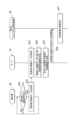
次に、図5を参照して、仮想空間画像生成システム100の動作の一例について説明する。図5は、サーバ10で生成された複合機40の仮想画像70を含む仮想空間画像50を、第2のウェアラブル端末装置30の表示部34に表示するケースにおける仮想空間画像生成システム100の動作を示すシーケンス図である。
次に、図5を参照して、仮想空間画像生成システム100の動作の一例について説明する。図5は、サーバ10で生成された複合機40の仮想画像70を含む仮想空間画像50を、第2のウェアラブル端末装置30の表示部34に表示するケースにおける仮想空間画像生成システム100の動作を示すシーケンス図である。
図5に示すように、先ず、サーバ10は、第1のウェアラブル端末装置20からアバターデータ232を取得する(ステップS1)。続けて、サーバ10は、第2のウェアラブル端末装置30からアバターデータ332を取得する(ステップS2)。ここで、アバターデータ232は、第1のウェアラブル端末装置20を装着しているユーザAにより指定されたアバターA1(アバター画像)を表示するためのデータである。また、アバターデータ332は、第2のウェアラブル端末装置30を装着しているユーザBにより指定されたアバターB1(アバター画像)を表示するためのデータである。
次いで、サーバ10は、所定の仮想空間テンプレートデータ、アバターデータ232、およびアバターデータ332に基づいて、ユーザAの分身であるアバターA1と、ユーザBの分身であるアバターB1と、によって共有される仮想空間画像(例えば、複合機40が設置されているエリア(エリア1)に対応する仮想空間画像50)を生成する(ステップS3)。
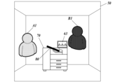
次いで、サーバ10は、ユーザBの分身であるアバターB1に係るアバター画像を第1のウェアラブル端末装置20に送信する(ステップS4)。第1のウェアラブル端末装置20は、サーバ10より受信したアバター画像(アバターB1)をバイザー241に投影させて表示する。図6は、第1のウェアラブル端末装置20を装着しているユーザAがバイザー241越しに視認したときの現実空間RSを示している。この現実空間RSは、複合機40が設置されているエリア(エリア1)の空間であって、図6に示すように、ユーザAは、複合機40を視認するとともに、ユーザBの分身であるアバターB1を拡張現実として視認する。
次いで、サーバ10は、ステップS3で生成した仮想空間画像50を第2のウェアラブル端末装置30に送信する(ステップS6)。そして、第2のウェアラブル端末装置30は、図7に示すように、サーバ10より受信した仮想空間画像50を表示部34に表示する(ステップS7)。
次いで、ユーザAが第1のウェアラブル端末装置20のカメラ254を用いて複合機40を撮像した場合、第1のウェアラブル端末装置20は、当該撮像画像をサーバ10に送信する(ステップS8)。そして、サーバ10は、第1のウェアラブル端末装置20より受信した撮像画像に基づいて、複合機40を識別する(ステップS9)。ここで、複合機40の識別は、上記撮像画像を解析することで行っているが、例えば、第1のウェアラブル端末装置20のカメラ254が読み取った複合機40の二次元コードを、当該第1のウェアラブル端末装置20より受信することで、当該複合機40を識別するようにしてもよい。また、第1のウェアラブル端末装置20より入力された複合機40のIDによって、当該複合機40を識別するようにしてもよい。また、複合機40の識別情報と、当該複合機40が設置されているエリア(エリア1)に係る情報と、が紐付けられて記憶部13に記憶されている場合にあっては、サーバ10が仮想空間画像50を生成する際に用いた仮想空間テンプレートデータの基となったエリアから複合機40を識別するようにしてもよい。
次いで、サーバ10は、ステップS9で識別した複合機40から所定の画面データを取得する(ステップS10)。具体的には、サーバ10は、上記の複合機40の表示部41に現在表示されている画面(例えば、〇△□が表示されている画面;図6参照)の画面データを取得する。例えば、サーバ10は、複合機40と直接的に通信し、または第1ウェアラブル装置20を介して間接的に複合機40と通信して当該複合機40から所定の画像データを取得してよい。なお、複合機40の表示部41が非表示の状態である場合には、例えば、当該複合機40の表示部41に表示される初期画面等の画面データを取得するようにしてもよい。また、対象となる画面データは、ステップS9で識別した複合機40から取得する場合に限られず、複合機40が表示部41に表示可能な各画面の画面データ群を格納している外部サーバ(図示省略)から取得するようにしてもよい。このとき、サーバ10は、ステップS9で取得した複合機40の識別情報を外部サーバに送信することに基づいて、当該外部サーバから画面データを取得してもよい。
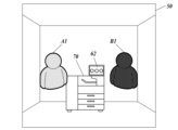
次いで、サーバ10は、ステップS10で取得した画面データに基づいて、仮想表示画面を生成する(ステップS11)。具体的には、サーバ10は、〇△□が表示されている画面の画面データを取得した場合、この〇△□が表示されている画面に係る仮想表示画面60を生成する。
次いで、サーバ10は、ステップS9で識別した複合機40の仮想画像70を生成する(ステップS12)。具体的には、サーバ10は、記憶部13に記憶されている仮想画像データに基づいて、ステップS9で識別した複合機40の仮想画像70を生成する。また、サーバ10は、ステップS8において第1のウェアラブル端末装置20から受信した複合機40の撮像画像に基づいて仮想画像70を生成してもよい。あるいは、サーバ10は、複合機40と通信して複合機40から仮想画像70を生成するためのデータを受信してもよい。
次いで、サーバ10は、ステップS12で生成した複合機40の仮想画像70の表示部に、ステップS11で生成した仮想表示画面60を合成する(ステップS13)。続けて、サーバ10は、仮想表示画面60を合成した仮想画像70を第2のウェアラブル端末装置30に送信する(ステップS14)。
次いで、第2のウェアラブル端末装置30は、図8に示すように、仮想表示画面60を合成した仮想画像70(複合機40の仮想画像70)を、表示部34に表示されている仮想空間画像50に表示する(ステップS15)。なお、例えば、アバターB1が仮想画像70から所定の距離以上離れたような場合、すなわち仮想表示画面60を視認し難くなったような場合、図9に示すように、仮想表示画面60の代替である吹き出し画面61を表示するようにしてもよい。また、第2のウェアラブル端末装置30を装着しているユーザBによる所定の操作に基づいて、仮想表示画面60による表示(図8参照)と、吹き出し画面61による表示(図9参照)と、のいずれかに切り替えられるようにしてもよい。
このように、第2のウェアラブル端末装置30が複合機40の仮想画像70を表示する際に、複合機40が表示部41に表示する画面に対応する仮想表示画面60を合成した仮想画像70を表示することで、よりリアルな仮想空間をユーザに体感させることが可能となる。
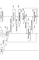
次に、図10を参照して、仮想空間画像生成システム100の動作の他の例について説明する。図10は、複合機40の表示部41で画面操作がなされたことに伴い、第2のウェアラブル端末装置30の表示部34に表示されている当該複合機40の仮想画像70を更新表示するケースにおける仮想空間画像生成システム100の動作を示すシーケンス図である。
図10に示すように、先ず、複合機40は、表示部41にて画面操作がなされたか否かを判定する(ステップS21)。
ステップS21において、表示部41にて画面操作がなされていないと判定された場合(ステップS21;NO)、複合機40は、当該画面操作がなされたと判定されるまでの間、ステップS21の判定処理を繰り返し行う。
また、ステップS21において、表示部41にて画面操作がなされたと判定された場合(ステップS21;YES)、複合機40は、当該画面操作に基づき変更された後の画面の画面データをサーバ10に送信する(ステップS22)。例えば、図11に示すように、表示部41の画面操作によって、〇〇〇が表示されている画面に変更された場合、複合機40は、〇〇〇が表示されている画面の画面データをサーバ10に送信する。そして、複合機40は、処理をステップS21に戻し、それ以降の処理を繰り返し行う。
次いで、サーバ10は、変更後の画面の画面データを複合機40から取得する(ステップS23)。なお、ステップS21において、表示部41の画面操作がなされたと判定された場合、複合機40は、当該画面操作に基づき変更された後の画面を識別可能な情報をサーバ10に送信し、サーバ10が、当該情報に基づいて、上述した外部サーバ(図示省略)から該当する画面データを取得するようにしてもよい。また、ステップS21において、表示部41の画面操作がなされたと判定された場合、複合機40は、当該画面操作に係る情報をサーバ10に送信し、サーバ10が、当該情報に対応する画面データを記憶部13から取得するようにしてもよい。かかる場合、複合機40の画面操作に係る情報と、当該画面操作により変更される画面の画面データと、を紐付けたUIデータが記憶部13に予め記憶されているものとする。
次いで、サーバ10は、ステップS23で取得した画面データに基づいて、仮想表示画面を生成する(ステップS24)。具体的には、サーバ10は、変更後の画面データとして、〇〇〇が表示されている画面の画面データを取得した場合、この〇〇〇が表示されている画面に係る仮想表示画面62を生成する。
次いで、サーバ10は、ステップS24で生成した仮想表示画面62を、複合機40の仮想画像70の表示部に合成する(ステップS25)。続けて、サーバ10は、仮想表示画面62を合成した仮想画像70を第2のウェアラブル端末装置30に送信する(ステップS26)。
次いで、第2のウェアラブル端末装置30は、図12に示すように、既に表示部34に表示されている仮想空間画像50において、仮想表示画面62を合成した仮想画像70(複合機40の仮想画像70)を更新表示する(ステップS27)。
このように、複合機40の表示部41で画面操作がなされた場合、当該画面操作に伴って、第2のウェアラブル端末装置30の表示部34に表示されている当該複合機40の仮想画像70を更新表示するので、より一層リアルな仮想空間をユーザに体感させることが可能となる。
次に、図13を参照して、仮想空間画像生成システム100の動作の他の例について説明する。図13は、第2のウェアラブル端末装置30の表示部34に表示されている仮想画像70(複合機40の仮想画像70)の仮想表示画面(例えば、仮想表示画面62;図12参照)に対してユーザ操作がなされてから当該仮想画像70を更新表示するまでの仮想空間画像生成システム100の動作を示すシーケンス図である。
図13に示すように、先ず、第2のウェアラブル端末装置30は、表示部34に表示されている仮想画像70(複合機40の仮想画像70)の仮想表示画面(例えば、仮想表示画面62;図12参照)に対する操作を受け付ける(ステップS31)。
次いで、第2のウェアラブル端末装置30は、ステップS31で受け付けた仮想表示画面の操作情報をサーバ10に送信する(ステップS32)。続けて、サーバ10は、第2のウェアラブル端末装置30より取得した仮想表示画面の操作情報を複合機40に送信する(ステップS33)。
次いで、複合機40は、サーバ10より取得した仮想表示画面の操作情報に基づいて、表示部41の画面を更新して表示する(ステップS34)。例えば、サーバ10より取得した仮想表示画面の操作情報が、〇〇〇が表示されている仮想表示画面62(図12参照)において、当該〇〇〇の表示を△△△の表示に変更する操作情報である場合、図14に示すように、複合機40は、当該操作情報に基づいて、〇〇〇が表示された状態から△△△が表示された状態に表示部41の画面を更新する。なお、サーバ10より取得した仮想表示画面の操作情報が、複合機40に所定の動作を実行させるための操作情報である場合、複合機40は、当該操作情報に対応する動作を実行する。
次いで、複合機40は、更新後(変更後)の画面の画面データをサーバ10に送信する(ステップS35)。例えば、図14に示すように、表示部41が△△△の画面に更新された場合、複合機40は、△△△の画面の画面データをサーバ10に送信する。
次いで、サーバ10は、更新後(変更後)の画面の画面データを複合機40から取得する(ステップS36)。なお、サーバ10は、仮想表示画面の操作情報と、当該操作情報に対応する更新後の画面の画面データと、が紐付けられたUIデータを記憶部13に格納している場合、ステップS32で第2のウェアラブル端末装置30より取得した仮想表示画面の操作情報に基づいて、記憶部13から該当する更新後の画面の画面データを取得するようにしてもよい。
次いで、サーバ10は、ステップS36で取得した画面データに基づいて、仮想表示画面を生成する(ステップS37)。具体的には、サーバ10は、更新後(変更後)の画面データとして、△△△が表示されている画面の画面データを取得した場合、この△△△が表示されている画面に係る仮想表示画面63を生成する。
次いで、サーバ10は、ステップS37で生成した仮想表示画面63を、複合機40の仮想画像70の表示部に合成する(ステップS38)。続けて、サーバ10は、仮想表示画面63を合成した仮想画像70を第2のウェアラブル端末装置30に送信する(ステップS39)。
次いで、第2のウェアラブル端末装置30は、図15に示すように、既に表示部34に表示されている仮想空間画像50において、仮想表示画面63を合成した仮想画像70(複合機40の仮想画像70)を更新表示する(ステップS40)。
なお、本実施形態の仮想空間画像生成システム100では、第2のウェアラブル端末装置30の台数を1台としているが2台以上でもよい。また、本実施形態の仮想空間画像生成システム100では、サーバ10の制御下において、第2のウェアラブル端末装置30の表示部34に仮想画像70を表示しているが、第2のウェアラブル端末装置30ごとに、当該仮想画像70に仮想表示画面や吹き出し画面を含ませるか否かを設定できるようにしてもよい。また、第2のウェアラブル端末装置30ごとに、仮想表示画面や吹き出し画面に対する操作を許可するか否かを設定できるようにしてもよい。
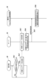
次に、図16を参照して、仮想空間画像生成システム100の動作の他の例について説明する。図16は、複合機40が所定の設置場所(例えば、エリア1)から別の場所(例えば、エリア2)に移動したケースにおける仮想空間画像生成システム100の動作を示すシーケンス図である。
図16に示すように、先ず、複合機40は、自機の直近の位置情報を定期的にサーバ10に送信する(ステップS31)。この位置情報は、例えば、所定のエリア(例えば、エリア1、エリア2など)に設置されているビーコン発信機(図示省略)から受信したビーコンIDであるものとするが、これ以外にも、所定のエリアに設置されているWiFi(登録商標)-AP(アクセスポイント)から受信した識別番号や、SLAM(Simultaneous Localization and Mapping)の技術により推定された自己位置情報、GNSS測位による位置情報等でもよい。また、複合機40は、上記の位置情報に基づいて、自機が当初の設置場所であるエリア1の外にあるか否かを判定し、当該判定の結果をサーバ10に送信するようにしてもよい。かかる場合、複合機40は、上記の位置情報に基づき自機の現在位置を特定可能な地図情報、および当初の設置場所を示す情報を有しているものとする。また、ユーザAが装着している第1のウェアラブル端末装置20が、自装置のカメラ254で撮像された撮像画像に基づいて、複合機40がエリア1の外にあるか否かを判定し、当該判定の結果を、サーバ10に送信するようにしてもよい。
次いで、サーバ10は、複合機40から取得した上記の位置情報に基づいて、当該複合機40が所定の設置場所であるエリア1の外にあるか否かを判定する(ステップS42)。ここで、サーバ10は、上記の位置情報に基づき現在位置を特定可能な地図情報、および複合機40の当初の設置場所を示す情報を記憶部13に格納しているものとする。なお、複合機40の設置場所であるエリア1は、或る部屋の空間全体に限られず、当該部屋の一部分であってもよい。
ステップS42において、複合機40が所定の設置場所であるエリア1の外にはない、すなわちエリア1内にあると判定された場合(ステップS42;NO)、サーバ10は、複合機40から送信される位置情報の取得を待機する。
また、ステップS42において、複合機40が所定の設置場所であるエリア1の外にあると判定された場合(ステップS42;YES)、サーバ10は、表示態様を変更した仮想画像71を第2のウェアラブル端末装置30に送信する(ステップS43)。
次いで、第2のウェアラブル端末装置30は、図17に示すように、サーバ10から取得した仮想画像71を仮想空間画像50に表示(更新表示)する(ステップS44)。ここで、仮想空間画像50は、複合機40の所定の設置場所であるエリア1に対応する仮想空間画像であるものとする。なお、図17では、複合機40の仮想画像に×印を重畳した画像を、表示態様を変更した仮想画像71としているが、例えば、複合機40がエリア1の外にあることを示す仮想画像、文字、記号等を表示したものを、表示態様を変更した仮想画像71としてもよい。また、複合機40の仮想画像の表示色を変更したものや、当該仮想画像を点滅表示させたもの、当該仮想画像を動作(例えば、左右に揺動)させたものを、表示態様を変更した仮想画像71としてもよい。また、表示態様を変更した仮想画像71を表示する場合、仮想表示画面(例えば、仮想表示画面63;図17参照)については非表示にしてもよい。また、複合機40がエリア1の外にあると判定された場合、サーバ10は、第2のウェアラブル端末装置30の表示部34に表示されている複合機40の仮想画像70を非表示の状態に変更する表示制御を行ってもよい。
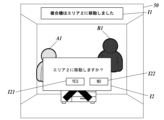
次いで、サーバ10は、複合機40の移動先を示す移動先情報I1と、当該移動先にユーザが移動するか否かを問いかける問いかけ情報I2と、を第2のウェアラブル端末装置30に送信する(ステップS45)。
次いで、第2のウェアラブル端末装置30は、図18に示すように、サーバ10から取得した移動先情報I1および問いかけ情報I2を仮想空間画像50に表示する。ここで、問いかけ情報I2は、画面形式となっており、移動先に移動することを指示するためのYESボタンI21と、移動先に移動しないことを指示するためのNOボタンI22と、が画面内に設けられている。
次いで、第2のウェアラブル端末装置30は、移動先に移動することを指示するユーザ操作(YESボタンI21の操作)がなされたか否かを判定する(ステップS47)。
ステップS47において、移動先に移動することを指示するユーザ操作(YESボタンI21の操作)がなされていないと判定された場合(ステップS47;NO)、第2のウェアラブル端末装置30は、複合機40の所定の設置場所であるエリア1に対応する仮想空間画像50の表示を継続する。
また、ステップS47において、移動先に移動することを指示するユーザ操作(YESボタンI21の操作)がなされたと判定された場合(ステップS47;YES)、第2のウェアラブル端末装置30は、移動先に移動することを指示する移動指示情報をサーバ10に送信する(ステップS48)。
次いで、サーバ10は、第2のウェアラブル端末装置30より上記の移動指示情報を取得したことを契機として、移動先の仮想空間画像(エリア2に対応した仮想空間画像51)を生成する(ステップS49)。
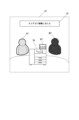
次いで、サーバ10は、ステップS49で生成した仮想空間画像(エリア2に対応した仮想空間画像51)を第2のウェアラブル端末装置30に送信する(ステップS50)。そして、第2のウェアラブル端末装置30は、図19に示すように、サーバ10より受信した仮想空間画像(エリア2に対応した仮想空間画像51)を表示部34に表示(更新表示)する(ステップS51)。このとき、第2のウェアラブル端末装置30の表示部34では、元の状態の仮想画像70(複合機40の仮想画像70)が表示されるとともに、移動先(エリア2)に移動したことを示す移動完了情報I3が表示されるようになっている。
このように、複合機40が所定の設置場所(例えば、エリア1)から別の場所(例えば、エリア2)に移動した場合、第2のウェアラブル端末装置30の表示部34に表示されている当該複合機40の仮想画像70の表示態様を変更することで、複合機40が移動したことをユーザに認識させることができるので、現実空間とのつながりが強い仮想空間を提供することができる。
次に、図20を参照して、仮想空間画像生成システム100の動作の他の例について説明する。図20は、複合機40での印刷動作に伴い、実際に印刷される記録媒体(用紙;ハード媒体)に対応する仮想記録媒体80を出力する態様の仮想画像70(複合機40の仮想画像70)を第2のウェアラブル端末装置30の表示部34に表示するケースでの仮想空間画像生成システム100の動作を示すシーケンス図である。
図20に示すように、先ず、複合機40は、自機に対して印刷指示操作がなされたか否かを判定する(ステップS61)。
ステップS61において、自機に対して印刷指示操作がなされていないと判定された場合(ステップS61;NO)、複合機40は、印刷指示操作がなされたと判定されるまでの間、ステップS61の判定処理を繰り返し行う。
また、ステップS61において、自機に対して印刷指示操作がなされたと判定された場合(ステップS61;YES)、複合機40は、印刷ジョブデータをサーバ10に送信する(ステップS62)。そして、複合機40は、処理をステップS61に戻し、それ以降の処理を繰り返し行う。ここで、印刷ジョブデータは、記録媒体に記録するソフトウェアデータと、当該ソフトウェアデータを記録することを示すハードコピー情報と、を含む。ハードコピー情報は、ハードコピーの実行を示す情報(トリガー情報)、ハードコピーの種類に係る情報(例えば、2D印刷)、記録媒体(ハード媒体)の固有情報(例えば、紙種、サイズ、色、デザイン等)、記録媒体への表示手段に関する固有情報(例えば、インクの種類、色等)などで構成される。
次いで、サーバ10は、印刷ジョブデータを複合機40から取得する(ステップS63)。続けて、サーバ10は、取得した印刷ジョブデータに基づいて、複合機40で実際に印刷される記録媒体に対応する仮想記録媒体80を生成する(ステップS64)。続けて、サーバ10は、生成した仮想記録媒体80を第2のウェアラブル端末装置30に送信する(ステップS65)。
次いで、第2のウェアラブル端末装置30は、サーバ10より取得した仮想記録媒体80に基づいて、図21に示すように、仮想記録媒体80を出力する態様の仮想画像70(複合機40の仮想画像70)を表示する(ステップS66)。具体的には、排紙トレイに仮想記録媒体80が徐々に排出される態様の仮想画像70を表示する。仮想記録媒体80が排出された後、例えば、当該仮想記録媒体80を指定するユーザ操作がなされると、図22に示すように、出力内容を視認可能な仮想記録媒体81が表示されるようになっている。
なお、仮想記録媒体80を出力する態様の仮想画像70(複合機40の仮想画像70)を表示するにあたり、複合機40が記録媒体を出力する過程をリアルに再現することは必ずしも必要ではなく、デフォルメした形で仮想記録媒体80を出力する仮想画像70(複合機40の仮想画像70)を表示してもよい。また、出力が完了した後の仮想記録媒体80は、複合機40の仮想画像70と独立して管理されるようにしてもよい。例えば、ユーザBの分身であるアバターB1が、仮想記録媒体80を持ち歩いて、別の仮想空間(例えば、仮想空間画像51)に移動できるようにしてもよい。また、アバターB1によって、仮想記録媒体80の編集(例えば、文字の付加、画像の付加、破棄等)を行えるようにしてもよい。また、ユーザBが仮想記録媒体80に対して実行可能な操作を、ユーザAによって設定できるようにしてもよい。具体的には、仮想記録媒体80を持ち運べるエリアを設定したり、当該仮想記録媒体80の2次コピーの可否や編集の可否等を設定できるようにしてもよい。
このように、複合機40での印刷動作に伴い、実際に印刷される記録媒体に対応する仮想記録媒体80を出力する態様の仮想画像70(複合機40の仮想画像70)を第2のウェアラブル端末装置30の表示部34に表示するので、より一層リアルな仮想空間をユーザに体感させることが可能となる。
<その他>
なお、上記実施形態は例示であり、様々な変更が可能である。
例えば、上記実施形態において、仮想空間画像生成システム100は、第1のウェアラブル端末装置20と、第2のウェアラブル端末装置30と、をそれぞれ1台ずつ備えているが、第1のウェアラブル端末装置20および第2のウェアラブル端末装置30の台数は特に限定されない。
なお、上記実施形態は例示であり、様々な変更が可能である。
例えば、上記実施形態において、仮想空間画像生成システム100は、第1のウェアラブル端末装置20と、第2のウェアラブル端末装置30と、をそれぞれ1台ずつ備えているが、第1のウェアラブル端末装置20および第2のウェアラブル端末装置30の台数は特に限定されない。
また、上記実施形態において、第1のウェアラブル端末装置20は、AR/MRゴーグルであるものとして説明したが、第2のウェアラブル端末装置30と同様に、VRゴーグルであってもよい。
また、上記実施形態において、仮想空間画像生成システム100は、第2のウェアラブル端末装置30を備え、当該第2のウェアラブル端末装置30の表示部34に仮想空間画像を表示しているが、例えば、デスクトップPCや、ノートPC、タブレットPC、スマートフォン等を備え、これらの端末装置の表示部に仮想空間画像を表示してもよい。
また、上記実施形態において、仮想空間画像生成システム100は、複合機40を1台備えているが、当該複合機40の台数は特に限定されない。また、仮想空間画像生成システム100は、複合機40に代えて、または複合機40に加えて、表示デバイスであるPC、電子ホワイトボード等を備えるようにしてもよい。
また、上記実施形態において、図20に示すケースでは、複合機40での印刷動作に伴い、実際に印刷される記録媒体(用紙;ハード媒体)に対応する仮想記録媒体80を出力する態様の仮想画像70(複合機40の仮想画像70)を第2のウェアラブル端末装置30の表示部34に表示しているが、複合機40以外に、例えば、金属や樹脂等への印刷が可能な特殊プリンタや、3Dプリンタ、ミシン等を適用することができる。かかる場合、上述したハードコピー情報は、ハードコピーの種類に係る情報(2D印刷、3D印刷、刺繍(ミシン用))、記録媒体(ハード媒体)の固有情報(材質(紙、樹脂、金属、布等)、サイズ、色、デザイン等)、記録媒体への表示手段に関する固有情報(例えば、インクの種類、色等)、糸の種類に係る情報、縫い方に関する情報などを含むようにする。そして、サーバ10は、ハードコピーの出力種別(2Dプリンタ、3Dプリンタ、ミシン)に紐付けて、上記のハードコピー情報のデフォルト値を記憶部13に記憶していてもよい。
その他、上記実施形態で示した構成および制御の具体的な細部は、本開示の趣旨を逸脱しない範囲において適宜変更可能である。また、本開示の趣旨を逸脱しない範囲において、上記実施の形態で示した構成および制御を適宜組み合わせ可能である。
本開示は、仮想空間画像生成方法および仮想空間画像生成システムに利用することができる。
100 仮想空間画像生成システム
10 サーバ
11 CPU
12 RAM
13 記憶部
131 プログラム
14 通信部
15 バス
20 第1のウェアラブル端末装置
21 CPU
22 RAM
23 記憶部
231 プログラム
232 アバターデータ
23 表示部
241 バイザー
242 レーザースキャナー
25 センサー部
251 加速度センサー
252 角速度センサー
253 深度センサー
254 カメラ
255 アイトラッカー
26 通信部
27 バス
30 第2のウェアラブル端末装置
31 CPU
32 RAM
33 記憶部
331 プログラム
332 アバターデータ
34 表示部
341 左目用表示部
342 右目用表示部
35 センサー部
351 加速度センサー
352 角速度センサー
353 カメラ
354 アイトラッカー
36 通信部
37 バス
40 複合機
10 サーバ
11 CPU
12 RAM
13 記憶部
131 プログラム
14 通信部
15 バス
20 第1のウェアラブル端末装置
21 CPU
22 RAM
23 記憶部
231 プログラム
232 アバターデータ
23 表示部
241 バイザー
242 レーザースキャナー
25 センサー部
251 加速度センサー
252 角速度センサー
253 深度センサー
254 カメラ
255 アイトラッカー
26 通信部
27 バス
30 第2のウェアラブル端末装置
31 CPU
32 RAM
33 記憶部
331 プログラム
332 アバターデータ
34 表示部
341 左目用表示部
342 右目用表示部
35 センサー部
351 加速度センサー
352 角速度センサー
353 カメラ
354 アイトラッカー
36 通信部
37 バス
40 複合機
Claims (20)
- 実空間に存在する表示デバイスを識別し、
識別した前記表示デバイスが表示可能な画像のデータを、当該表示デバイス又は当該データが格納されたストレージから取得し、
取得した前記画像のデータに基づいて、前記表示デバイスが表示可能な画像に対応する仮想表示画像を含む仮想空間画像を生成する、仮想空間画像生成方法。 - 識別した前記表示デバイスが表示する画像が変更された場合、当該変更後の画像のデータを、当該表示デバイス又は当該データが格納されたストレージから取得し、
取得した前記変更後の画像のデータに基づいて、前記仮想空間画像に含まれる前記仮想表示画像を更新する、請求項1に記載の仮想空間画像生成方法。 - 前記実空間に存在する前記表示デバイスが操作された場合、当該操作に係る情報を当該表示デバイスから取得し、
取得した前記操作に係る情報に基づいて、前記仮想空間画像に含まれる前記仮想表示画像を更新する、請求項1又は2に記載の仮想空間画像生成方法。 - 前記仮想表示画像に対する操作が行われた場合、当該操作に係る情報を前記実空間に存在する前記表示デバイスに送信し、
前記表示デバイスが、受信した前記操作に係る情報に基づいて、当該操作に対応する動作を実行する、請求項1~3のいずれか一項に記載の仮想空間画像生成方法。 - 前記操作に対応する動作は、前記表示デバイスが表示する画像を更新する動作である、請求項4に記載の仮想空間画像生成方法。
- 前記実空間に存在する前記表示デバイスにおいて前記更新が行われた場合、当該更新後の画像のデータを、当該表示デバイス又は当該データが格納されたストレージから取得し、
取得した前記更新後の画像のデータに基づいて、前記仮想空間画像に含まれる前記仮想表示画像を更新する、請求項5に記載の仮想空間画像生成方法。 - 前記実空間に存在する前記表示デバイスにおいて前記更新が行われた場合、前記操作に伴い表示される画像のデータに基づいて、前記仮想空間画像に含まれる前記仮想表示画像を更新する、請求項5に記載の仮想空間画像生成方法。
- 前記仮想空間画像を表示する端末装置ごとに、当該仮想空間画像中に前記仮想表示画像を含ませるか否かを設定可能とする、請求項1~7のいずれか一項に記載の仮想空間画像生成方法。
- 前記仮想空間画像を表示する端末装置ごとに、当該仮想空間画像中の前記仮想表示画像に対する操作を許可するか否かを設定可能とする、請求項1~8のいずれか一項に記載の仮想空間画像生成方法。
- 前記実空間に存在する前記表示デバイスの撮像画像に基づいて、当該表示デバイスの仮想画像を生成し、
生成した前記表示デバイスの仮想画像を前記仮想空間画像に含める、請求項1~9のいずれか一項に記載の仮想空間画像生成方法。 - 前記仮想表示画像を合成した前記表示デバイスの仮想画像を前記仮想空間画像に含める、請求項10に記載の仮想空間画像生成方法。
- 前記実空間に存在する前記表示デバイスの位置情報を取得し、
取得した前記位置情報に基づいて、前記表示デバイスが所定のエリアから移動したと判断した場合、当該表示デバイスの前記仮想画像の表示態様を変更する、請求項10又は11に記載の仮想空間画像生成方法。 - 前記仮想表示画像の表示中に前記仮想画像の表示態様を変更する場合、当該仮想表示画像の表示を継続する、請求項12に記載の仮想空間画像生成方法。
- 前記実空間に存在する前記表示デバイスの位置情報を取得し、
取得した前記位置情報に基づいて、前記表示デバイスが所定のエリアから移動したと判断した場合、当該表示デバイスの前記仮想画像を非表示にする、請求項10又は11に記載の仮想空間画像生成方法。 - 前記仮想表示画像の表示中に前記仮想画像を非表示にする場合、当該仮想表示画像の表示を継続する、請求項14に記載の仮想空間画像生成方法。
- 前記表示デバイスが所定のエリアから移動したと判断した場合、当該表示デバイスの移動先を示す移動先情報を前記仮想空間画像に含める、請求項12~15のいずれか一項に記載の仮想空間画像生成方法。
- 前記表示デバイスが所定のエリアから移動したと判断した場合、当該表示デバイスの移動先に移動するか否かの問いかけ情報を前記仮想空間画像に含め、
前記移動先に移動することを示すユーザ操作と、当該移動先に移動しないことを示すユーザ操作と、のいずれかを受け付ける、請求項12~16のいずれか一項に記載の仮想空間画像生成方法。 - 前記移動先に移動することを示すユーザ操作を受け付けた場合、前記仮想空間画像を、前記所定のエリアに対応する仮想空間画像から、当該移動先のエリアに対応する仮想空間画像に変更する、請求項17に記載の仮想空間画像生成方法。
- 前記表示デバイスは、ソフトウェアデータを、ハード媒体を介して出力する出力手段を備え、
前記実空間に存在する前記表示デバイスにおいて、所定のソフトウェアデータを、前記ハード媒体を介して出力する操作が行われた場合、当該操作に係る情報を当該表示デバイスから取得し、
取得した前記操作に係る情報に基づいて、前記所定のソフトウェアデータが出力された前記ハード媒体の仮想画像を前記仮想空間画像に含める、請求項10~18のいずれか一項に記載の仮想空間画像生成方法。 - 実空間に存在する表示デバイスを識別し、
識別した前記表示デバイスが表示可能な画像のデータを、当該表示デバイス又は当該データが格納されたストレージから取得し、
取得した前記画像のデータに基づいて、前記表示デバイスが表示可能な画像に対応する仮想表示画像を含む仮想空間画像を生成する、仮想空間画像生成システム。
Priority Applications (2)
| Application Number | Priority Date | Filing Date | Title |
|---|---|---|---|
| JP2024536588A JP7817407B2 (ja) | 2022-07-26 | 2022-07-26 | 仮想空間画像生成方法および仮想空間画像生成システム |
| PCT/JP2022/028751 WO2024023922A1 (ja) | 2022-07-26 | 2022-07-26 | 仮想空間画像生成方法および仮想空間画像生成システム |
Applications Claiming Priority (1)
| Application Number | Priority Date | Filing Date | Title |
|---|---|---|---|
| PCT/JP2022/028751 WO2024023922A1 (ja) | 2022-07-26 | 2022-07-26 | 仮想空間画像生成方法および仮想空間画像生成システム |
Publications (1)
| Publication Number | Publication Date |
|---|---|
| WO2024023922A1 true WO2024023922A1 (ja) | 2024-02-01 |
Family
ID=89705618
Family Applications (1)
| Application Number | Title | Priority Date | Filing Date |
|---|---|---|---|
| PCT/JP2022/028751 Ceased WO2024023922A1 (ja) | 2022-07-26 | 2022-07-26 | 仮想空間画像生成方法および仮想空間画像生成システム |
Country Status (2)
| Country | Link |
|---|---|
| JP (1) | JP7817407B2 (ja) |
| WO (1) | WO2024023922A1 (ja) |
Citations (1)
| Publication number | Priority date | Publication date | Assignee | Title |
|---|---|---|---|---|
| JP2021068383A (ja) * | 2019-10-28 | 2021-04-30 | 富士ゼロックス株式会社 | 情報処理装置、及び、情報処理プログラム |
Family Cites Families (1)
| Publication number | Priority date | Publication date | Assignee | Title |
|---|---|---|---|---|
| JP7446754B2 (ja) | 2019-09-30 | 2024-03-11 | キヤノン株式会社 | 画像処理装置、画像処理方法、及びプログラム |
-
2022
- 2022-07-26 WO PCT/JP2022/028751 patent/WO2024023922A1/ja not_active Ceased
- 2022-07-26 JP JP2024536588A patent/JP7817407B2/ja active Active
Patent Citations (1)
| Publication number | Priority date | Publication date | Assignee | Title |
|---|---|---|---|---|
| JP2021068383A (ja) * | 2019-10-28 | 2021-04-30 | 富士ゼロックス株式会社 | 情報処理装置、及び、情報処理プログラム |
Non-Patent Citations (2)
| Title |
|---|
| ANONYMOUS: "[How to display your PC in VR with Horizon Workrooms]", VR EXPERIENCE KNOWLEDGE: INFORMATION BLOG FOR VR LOVERS BY VR LOVERS, 22 September 2021 (2021-09-22), XP009553178, Retrieved from the Internet <URL:https://web.archive.org/web/20210922083242/https://keikenchi.com/how-to-display-your-pc-in-vr-with-horizon-workrooms> * |
| ANONYMOUS: "How to display the keyboard in VR with Horizon Workrooms", VR EXPERIENCE KNOWLEDGE: INFORMATION BLOG FOR VR LOVERS BY VR LOVERS, 22 September 2021 (2021-09-22), XP009553181, Retrieved from the Internet <URL:https://web.archive.org/web/20210922075215/https://keikenchi.com/how-to-make-the-keyboard-appear-in-vr-in-horizon-workrooms> * |
Also Published As
| Publication number | Publication date |
|---|---|
| JPWO2024023922A1 (ja) | 2024-02-01 |
| JP7817407B2 (ja) | 2026-02-18 |
Similar Documents
| Publication | Publication Date | Title |
|---|---|---|
| US20220153412A1 (en) | Control method, control system, and smart glasses for first person view unmanned aerial vehicle flight | |
| JP6899875B2 (ja) | 情報処理装置、映像表示システム、情報処理装置の制御方法、及びプログラム | |
| US9810913B2 (en) | Smart head-mounted projection system | |
| JP4883774B2 (ja) | 情報処理装置及びその制御方法、プログラム | |
| US20140256429A1 (en) | Image display system and head-mounted display device | |
| CN110377148B (zh) | 计算机可读介质、训练对象检测算法的方法及训练设备 | |
| JP2014194725A (ja) | ジョブ情報表示装置 | |
| WO2022201433A1 (ja) | ウェアラブル端末装置、プログラムおよび表示方法 | |
| WO2022208595A1 (ja) | ウェアラブル端末装置、プログラムおよび報知方法 | |
| US12353614B2 (en) | Wearable terminal apparatus, program, display method, and virtual image distribution system | |
| JP7817407B2 (ja) | 仮想空間画像生成方法および仮想空間画像生成システム | |
| JPWO2012131862A1 (ja) | 画像処理装置、立体画像表示装置、方法およびプログラム | |
| US12288305B2 (en) | Wearable terminal apparatus to change display position of partial image | |
| CN112581630B (zh) | 一种用户交互方法和系统 | |
| JP2024079765A (ja) | ウェアラブル端末装置、プログラムおよび表示方法 | |
| US20240296632A1 (en) | Wearable terminal apparatus, program, and display method | |
| JP7760742B2 (ja) | 仮想画像共有方法および仮想画像共有システム | |
| JP2595942B2 (ja) | 立体画像表示装置 | |
| WO2022208612A1 (ja) | ウェアラブル端末装置、プログラムおよび表示方法 | |
| US12340462B2 (en) | Wearable terminal device, program, and display method | |
| US20260095647A1 (en) | Information processing apparatus, information processing system, method for controlling information processing apparatus, and storage medium | |
| US11176911B2 (en) | Information processing apparatus, information processing method, program, and head-mounted display | |
| JP5332127B2 (ja) | 頭部装着型表示装置 | |
| JP2025114391A (ja) | 情報処理装置、情報処理装置の制御方法、システム、及びプログラム | |
| JP2018206103A (ja) | ヘッドマウントディスプレイおよび作業支援システム |
Legal Events
| Date | Code | Title | Description |
|---|---|---|---|
| 121 | Ep: the epo has been informed by wipo that ep was designated in this application |
Ref document number: 22953019 Country of ref document: EP Kind code of ref document: A1 |
|
| ENP | Entry into the national phase |
Ref document number: 2024536588 Country of ref document: JP Kind code of ref document: A |
|
| NENP | Non-entry into the national phase |
Ref country code: DE |
|
| 122 | Ep: pct application non-entry in european phase |
Ref document number: 22953019 Country of ref document: EP Kind code of ref document: A1 |