WO2024019086A1 - Sealing device, sealing structure, and assembly method for sealing structure - Google Patents
Sealing device, sealing structure, and assembly method for sealing structure Download PDFInfo
- Publication number
- WO2024019086A1 WO2024019086A1 PCT/JP2023/026414 JP2023026414W WO2024019086A1 WO 2024019086 A1 WO2024019086 A1 WO 2024019086A1 JP 2023026414 W JP2023026414 W JP 2023026414W WO 2024019086 A1 WO2024019086 A1 WO 2024019086A1
- Authority
- WO
- WIPO (PCT)
- Prior art keywords
- sealing device
- seal
- groove
- housing
- rotor
- Prior art date
Links
- 238000007789 sealing Methods 0.000 title claims abstract description 271
- 238000000034 method Methods 0.000 title description 5
- 230000002093 peripheral effect Effects 0.000 claims abstract description 45
- 238000005452 bending Methods 0.000 claims abstract description 9
- 230000000052 comparative effect Effects 0.000 description 14
- 239000000463 material Substances 0.000 description 10
- 239000012530 fluid Substances 0.000 description 9
- 230000000694 effects Effects 0.000 description 7
- 229920001971 elastomer Polymers 0.000 description 6
- 239000000806 elastomer Substances 0.000 description 6
- 239000007787 solid Substances 0.000 description 5
- 239000002826 coolant Substances 0.000 description 4
- 230000004048 modification Effects 0.000 description 3
- 238000012986 modification Methods 0.000 description 3
- 230000004044 response Effects 0.000 description 3
- 229920003051 synthetic elastomer Polymers 0.000 description 3
- 239000005061 synthetic rubber Substances 0.000 description 3
- 239000013013 elastic material Substances 0.000 description 2
- 229920000840 ethylene tetrafluoroethylene copolymer Polymers 0.000 description 2
- 229920002493 poly(chlorotrifluoroethylene) Polymers 0.000 description 2
- 239000005023 polychlorotrifluoroethylene (PCTFE) polymer Substances 0.000 description 2
- -1 polytetrafluoroethylene Polymers 0.000 description 2
- 229920001343 polytetrafluoroethylene Polymers 0.000 description 2
- 239000004810 polytetrafluoroethylene Substances 0.000 description 2
- 229920002943 EPDM rubber Polymers 0.000 description 1
- 230000006835 compression Effects 0.000 description 1
- 238000007906 compression Methods 0.000 description 1
- 238000001816 cooling Methods 0.000 description 1
- 239000013256 coordination polymer Substances 0.000 description 1
- 230000006866 deterioration Effects 0.000 description 1
- 238000010586 diagram Methods 0.000 description 1
- 230000005489 elastic deformation Effects 0.000 description 1
- 230000001771 impaired effect Effects 0.000 description 1
- 239000007788 liquid Substances 0.000 description 1
- 239000012858 resilient material Substances 0.000 description 1
- 229920005989 resin Polymers 0.000 description 1
- 239000011347 resin Substances 0.000 description 1
- 229920005992 thermoplastic resin Polymers 0.000 description 1
- 230000009466 transformation Effects 0.000 description 1
- 230000007306 turnover Effects 0.000 description 1
Images


Classifications
-
- F—MECHANICAL ENGINEERING; LIGHTING; HEATING; WEAPONS; BLASTING
- F16—ENGINEERING ELEMENTS AND UNITS; GENERAL MEASURES FOR PRODUCING AND MAINTAINING EFFECTIVE FUNCTIONING OF MACHINES OR INSTALLATIONS; THERMAL INSULATION IN GENERAL
- F16J—PISTONS; CYLINDERS; SEALINGS
- F16J15/00—Sealings
- F16J15/16—Sealings between relatively-moving surfaces
- F16J15/18—Sealings between relatively-moving surfaces with stuffing-boxes for elastic or plastic packings
- F16J15/24—Sealings between relatively-moving surfaces with stuffing-boxes for elastic or plastic packings with radially or tangentially compressed packing
-
- F—MECHANICAL ENGINEERING; LIGHTING; HEATING; WEAPONS; BLASTING
- F16—ENGINEERING ELEMENTS AND UNITS; GENERAL MEASURES FOR PRODUCING AND MAINTAINING EFFECTIVE FUNCTIONING OF MACHINES OR INSTALLATIONS; THERMAL INSULATION IN GENERAL
- F16J—PISTONS; CYLINDERS; SEALINGS
- F16J15/00—Sealings
- F16J15/16—Sealings between relatively-moving surfaces
- F16J15/32—Sealings between relatively-moving surfaces with elastic sealings, e.g. O-rings
- F16J15/3204—Sealings between relatively-moving surfaces with elastic sealings, e.g. O-rings with at least one lip
- F16J15/3232—Sealings between relatively-moving surfaces with elastic sealings, e.g. O-rings with at least one lip having two or more lips
Definitions
- the present disclosure relates to a sealing device, a sealing structure, and a method of assembling the sealing structure.
- a rotary valve device is known as a device that switches the flow state of fluid flowing through a plurality of channels provided in one mechanical system.
- the electric vehicle thermal management system TM shown in FIG. 1 includes four circulation channels CF1, CF2, CF3, and CF4 through which coolant flows, and a multi-port valve V10 as an example of a rotary type valve device.
- the circulation flow path CF1 is provided around the battery part BT.
- the circulation channel CF2 is provided around the heat exchanger R1 and includes a pump P1.
- the circulation flow path CF3 is provided around the heat exchanger R2 and the condenser C2, and has a tank RT.
- the circulation channel CF4 is provided around the electronic component ED and the axle AX, and includes a pump P2.
- the multi-port valve V10 is provided so that the circulation channels CF1 to CF4 can merge with each other.
- Multiport valve V10 has a housing V2, a rotor V3, and a sealing device V4.
- the housing V2 has a plurality of port portions V2a connected to each of the circulation channels CF1 to CF4.
- the rotor V3 is rotatably provided inside the housing V2 around the central axis OV.
- the rotor V3 includes a plurality of port sections V3a that can be connected to the port section V2a, and a plurality of flow paths V3b that connect two port sections V3a among the plurality of port sections V3a.
- the sealing device V4 seals between the housing V2 and the rotor V3 in a state where the coolant can flow between the port portion V2a and the port portion V3a.
- the multi-port valve V10 switches the mutual connection state of the circulation channels CF1 to CF4 and the flow state of the coolant flowing through the circulation channels CF1 to CF4.
- another circulation flow path including an evaporator ER, an accumulator AR, a compressor CP, and a condenser C1 is provided around the heat exchanger R2 and the condenser C2.
- the structure of a rotary type valve device includes a valve body (i.e., a housing) having a valve chamber, and a valve body disposed inside the valve chamber, as described in Japanese Patent Application Laid-Open No. 2018-96543 (hereinafter referred to as Patent Document 1).
- a valve body i.e., a rotor
- the sealing member having a cylindrical body (i.e., a first sealing portion) and an outer rib (i.e., , a second seal portion), and a seal member having a second seal portion) are known.
- the sealing member described in Patent Document 1 has a cylindrical body and an outer rib that are integrally molded, and is made of an elastic material such as synthetic rubber.
- the outer ribs formed from a resilient material have a solid cross section.
- the outer rib generates a reaction force corresponding to a fitting force applied from the valve body toward the central axis of the cylindrical body when assembled as a valve device, and transmits the reaction force to the cylindrical body.
- the reaction force generated on the outer rib is an elastic force caused by the elastic material.
- the reaction force exerted by the outer rib acts on the cylindrical body in the same direction as the fitting force, increasing the axial force exerted by the inner periphery of the cylindrical body.
- the present disclosure aims to reduce the radial component of the reaction force transmitted from the second seal portion to the first seal portion during assembly.
- a first aspect of the present disclosure is a sealing device assembled between a cylindrical housing and a rotor that is coaxially arranged inside the housing and rotates about an axis.
- the sealing device is A first seal portion having a main body portion along an outer diameter portion of the rotor, a port portion that penetrates the main body portion in a radial direction; A groove portion formed on the outer peripheral surface of the main body portion, the groove portion having a groove bottom parallel to the outer peripheral surface, and formed to surround the port portion when viewed from the outer peripheral surface side in the radial direction.
- a groove and a first seal portion having a a second seal part that is attached to the groove part so as to be in contact with the groove bottom and seals between the housing and the first seal part, the second seal part having a bent part that can be bent during assembly;
- the seal part of has.
- a second aspect of the present disclosure is a sealing device assembled between a cylindrical housing and a rotor that is coaxially arranged inside the housing and rotates about an axis.
- the sealing device is A first seal portion having a main body portion along an outer diameter portion of the rotor, a port portion that penetrates the main body portion in a radial direction; A groove portion formed on the outer peripheral surface of the main body portion, the groove portion having a groove bottom parallel to the outer peripheral surface, and formed to surround the port portion when viewed from the outer peripheral surface side in the radial direction.
- a groove and a first seal portion having a a second seal part that is attached to the groove part so as to be in contact with the groove bottom and seals between the housing and the first seal part, the second seal part being bent in a direction intersecting the radial direction when assembled; a second seal portion having a possible bend; has.
- a third aspect of the present disclosure is a sealing device assembled between a cylindrical housing and a rotor that is coaxially arranged inside the housing and rotates around an axis.
- the sealing device is A first seal portion having a main body portion along an outer diameter portion of the rotor, a port portion that penetrates the main body portion in a radial direction; A groove portion formed on the outer peripheral surface of the main body portion, the groove portion having a groove bottom parallel to the outer peripheral surface, and formed to surround the port portion when viewed from the outer peripheral surface side in the radial direction.
- a fourth aspect of the present disclosure is a sealing device assembled between a cylindrical housing and a rotor that is coaxially arranged inside the housing and rotates about an axis.
- the sealing device is A first seal portion having a main body portion along an outer diameter portion of the rotor, a port portion that penetrates the main body portion in a radial direction; A groove portion formed on the outer peripheral surface of the main body portion, the groove portion having a groove bottom parallel to the outer peripheral surface, and formed to surround the port portion when viewed from the outer peripheral surface side in the radial direction.
- a groove and a first seal portion having a a second seal part that is attached to the groove part so as to be in contact with the groove bottom and seals between the housing and the first seal part, the second seal part being bent in a direction intersecting the radial direction when assembled; a possible second seal portion; has.
- a fifth aspect of the present disclosure is a sealed structure.
- the sealed structure is a cylindrical housing; a rotor that is coaxially arranged inside the housing and rotates about an axis; A first seal portion having a main body portion along an outer diameter portion of the rotor, a port portion that penetrates the main body portion in a radial direction; A groove portion formed on the outer peripheral surface of the main body portion, the groove portion having a groove bottom parallel to the outer peripheral surface, and formed to surround the port portion when viewed from the outer peripheral surface side in the radial direction.
- a groove and a first seal portion having a a second seal part that is attached to the groove part so as to be in contact with the groove bottom and seals between the housing and the first seal part in a bent state; has.
- a sixth aspect of the present disclosure is a sealed structure.
- the sealed structure is a cylindrical housing; a rotor that is coaxially arranged inside the housing and rotates about an axis; A first seal portion having a main body portion along an outer diameter portion of the rotor, a port portion that penetrates the main body portion in a radial direction; A groove portion formed on the outer peripheral surface of the main body portion, the groove portion having a groove bottom parallel to the outer peripheral surface, and formed to surround the port portion when viewed from the outer peripheral surface side in the radial direction.
- a groove and a first seal portion having a a second seal part that is attached to the groove part so as to be in contact with the groove bottom and seals between the housing and the first seal part in a bent state in a direction intersecting the radial direction; has.
- a seventh aspect of the present disclosure is a sealing device assembled between a cylindrical housing and a rotor that is coaxially arranged inside the housing and rotates about an axis.
- the sealing device is A first seal portion having a main body portion along an outer diameter portion of the rotor, a port portion that penetrates the main body portion in a radial direction; A groove formed in the outer circumferential surface of the main body portion so as to surround the port portion when viewed from the outer circumferential surface side in the radial direction, the groove portion having a pair of inclined surfaces that open toward the housing side.
- An eighth aspect of the present disclosure is a sealing device assembled between a cylindrical housing and a rotor that is coaxially arranged inside the housing and rotates about an axis.
- the sealing device is A first seal portion having a main body portion along an outer diameter portion of the rotor, a port portion that penetrates the main body portion in a radial direction; A groove formed in the outer circumferential surface of the main body section so as to surround the port section when viewed from the outer circumferential surface side in the radial direction, the groove section being linear in a direction intersecting the radial direction when viewed in cross section.
- a groove portion having a pair of sloped surfaces that are sloped at a distance, and a groove depth; a first seal portion having a a second seal part that is attached to the groove part and seals between the housing and the first seal part, the second seal part being in contact with the pair of inclined surfaces; has The inner part of the groove forms a first gap with the second seal part, The second seal portion is deformable toward the first gap during assembly.
- Another aspect of the present disclosure is the sealing device according to any one of the first aspect to the fourth aspect, the seventh aspect, and the eighth aspect, wherein the second seal part has a hollow circular shape. It may have a cross section.
- Another aspect of the present disclosure is the sealing device according to any one of the first to fourth aspects, the seventh aspect, and the eighth aspect, wherein the second seal portion has a C-shape. It may have a cross section.
- Another aspect of the present disclosure is the sealing device according to any one of the first aspect to the fourth aspect, the seventh aspect, and the eighth aspect, wherein the second seal portion is a substantially solid circle.
- the second seal portion may have a slit-shaped opening extending from the outer periphery of the cross-section toward the center of the cross-section of the second seal portion.
- Another aspect of the present disclosure is the sealing device according to any one of the first to fourth aspects, the seventh aspect, and the eighth aspect, wherein the second seal portion is in contact with the housing.
- the housing includes an outer end portion that extends from a first direction in the axial direction relative to the first seal portion toward a second direction opposite to the first direction. It may come into contact with the outer end portion during assembly by movement.
- the radial component of the reaction force transmitted from the second seal portion to the first seal portion during assembly can be reduced.
- FIG. 1 is a schematic diagram of an electric vehicle cooling system including a rotary type valve device.
- FIG. 2 is an exploded perspective view of the sealing structure of the first embodiment.
- FIG. 3 is a longitudinal cross-sectional view of the sealing structure of the first embodiment. It is a perspective view of the sealing device of a 1st embodiment.
- FIG. 2 is an enlarged sectional view of the sealing device of the first embodiment. (a) is an enlarged cross-sectional view of a state in which only one open end of the second seal portion of the first embodiment is in contact with the edge of the housing. (b) is an enlarged sectional view of a state in which the other open end of the second seal portion of the first embodiment is in contact with the edge of the housing.
- FIG. 3 is an enlarged sectional view of a sealing device according to a second embodiment.
- (a) is an enlarged sectional view when the housing inserted relatively to the sealing structure starts to come into contact with the folded end of the second sealing part during assembly of the sealing structure of the second embodiment. .
- FIG. 7 is an enlarged sectional view of a sealing device according to a third embodiment. It is an enlarged sectional view of the sealing device of a 4th embodiment. It is an enlarged sectional view of the sealing device of a 5th embodiment. It is an enlarged sectional view of the sealing device of a 6th embodiment. It is an enlarged sectional view of the sealing device of a 7th embodiment.
- FIG. 7 is an enlarged cross-sectional view of a modification of the sealing device according to the present disclosure.
- FIG. 7 is an enlarged cross-sectional view of a modification of the sealing device according to the present disclosure.
- (a) is an enlarged sectional view when the second seal portion of the modified example of the sealing device according to the present disclosure is not in contact with the housing.
- (b) is an enlarged sectional view when assembly of a modified example of the sealing device according to the present disclosure is completed.
- the sealing structure 10 is a rotary valve device that switches the flow state of fluid flowing through a plurality of channels provided in one mechanical system (not shown).
- the sealing structure 10 of the first embodiment includes a housing 20, a rotor 30, and a sealing device 40, as shown in FIGS. 2 and 3.
- the housing 20 has a hollow cylindrical shape extending along the central axis CA.
- the housing 20 has a plurality of (four in this embodiment) port holes 20p on the cylindrical surface.
- the plurality of port holes 20p are formed side by side along the circumferential direction.
- Each port hole 20p penetrates the cylindrical surface in the radial direction.
- Housing 20 has an inner peripheral surface 20b.
- the housing 20 has a locking means (not shown).
- the housing 20 is engageable with a first engagement portion (not shown) provided around the sealing structure 10 in a mechanical system (not shown). By engaging the locking means with the first engagement part, the housing 20 is fixed relative to the mechanical system.
- the rotor 30 has a substantially cylindrical shape and is arranged coaxially inside the housing 20.
- the rotor 30 is rotatable around the central axis CA.
- the rotor 30 has a main body portion 32, a protrusion portion 33, and a flow path portion 34.
- the main body portion 32 has a cylindrical shape extending along the central axis CA.
- the main body portion 32 has an outer diameter portion 32a and a plurality of (in this embodiment, two) port holes 30p.
- the plurality of port holes 30p are arranged along the circumferential direction on the outer diameter portion 32a.
- the protrusion 33 has a cylindrical shape extending along the central axis CA.
- the protruding portion 33 protrudes from the end surface 32e of the main body portion 32.
- An opening 36a is formed in the end surface of the protrusion 33.
- the flow path section 34 is formed inside the rotor 30.
- the flow path portion 34 includes a first flow path 36, a plurality of second flow paths 38, and a merging portion 34a.
- the first flow path 36 extends from the opening 36a of the protrusion 33 into the main body 32 in the axial direction.
- the second flow path 38 extends in the radial direction from each of the port holes 30p of the main body 32 into the interior of the main body 32.
- the plurality of second flow paths 38 correspond to each of the plurality of port holes 30p.
- the first flow path 36 and the plurality of second flow paths 38 merge at the merge portion 34a. Note that the rotor 30 does not need to have the first flow path 36 and the opening 36a.
- the plurality of second flow paths 38 may be configured to be connected to each other.
- Each of the port holes 30p of the rotor 30 faces one of the port holes 20p of the housing 20 when the rotatable rotor 30 is in a predetermined phase. At this time, the fluid flowing through the second flow path 38 flows to the port hole 20p of the housing 20 facing the port hole 30p via a port portion 51p of the sealing device 40, which will be described later.
- the combination of the port hole 30p of the rotor 30 and the port hole 20p of the housing 20 that faces the port hole 30p changes depending on the phase of the rotor 30. That is, by changing the phase of the rotor 30 as the rotor 30 rotates, the combination of the port holes 30p and the port holes 20p changes. This switches the state of fluid flow through the mechanical system.
- the fluid flowing through the sealing structure 10 is, for example, a liquid such as oil or long life coolant (LLC).
- a liquid such as oil or long life coolant (LLC).
- the sealing device 40 is assembled between the housing 20 and the rotor 30, as shown in FIG.
- the sealing device 40 includes a first seal portion 50 and a second seal portion 60.
- the first seal portion 50 has a substantially cylindrical shape. As shown in FIG. 3, the first seal portion 50 is arranged along the outer diameter portion 32a of the rotor 30 during assembly.
- the first seal portion 50 includes a main body portion 51, a plurality of (four in this embodiment) port portions 51p, and a groove portion 54.
- the main body portion 51 has a hollow cylindrical shape extending along the central axis CA.
- the main body portion 51 has an inner circumferential surface 51a and an outer circumferential surface 51b.
- the inner circumferential surface 51a of the main body portion 51 faces the outer diameter portion 32a of the rotor 30 during assembly.
- the main body portion 51 is formed from a resin material.
- the main body portion 51 is preferably formed from a thermoplastic resin material. More preferably, the main body portion 51 is made of a fluororesin such as polytetrafluoroethylene (PTFE), ethylene-tetrafluoroethylene copolymer (ETFE), or polychlorotrifluoroethylene (PCTFE).
- the main body portion 51 may be made of an elastomer such as synthetic rubber. Note that the material forming the main body portion 51 preferably has higher rigidity than the material forming the second seal portion 60 described later. Further, it is preferable that the surface of the main body portion 51 has a lower coefficient of friction than the surface of the second seal portion 60.
- the main body portion 51 has a plurality of locking portions 52 and a plurality of locking portions 53.
- the locking portion 52 protrudes in the first axial direction from a part of the edge of the main body portion 51 in the first axial direction along the central axis CA.
- the locking portion 53 protrudes in the second axial direction from a part of the edge of the main body portion 51 in the second axial direction on the opposite side to the first axial direction.
- the plurality of locking parts 52 and 53 are arranged along the circumferential direction of the main body part 51.
- the locking parts 52, 53 are each engageable with a second engaging part (not shown) provided around the sealing structure 10 in a mechanical system (not shown).
- the main body portion 51 is fixed relative to the mechanical system by engaging the locking portions 52, 53 with the second engaging portions.
- Each port portion 51p penetrates the main body portion 51 in the radial direction.
- the plurality of port portions 51p correspond to the port holes 20p of the housing 20.
- the groove portion 54 is formed in a concave shape with respect to the outer circumferential surface 51b of the main body portion 51.
- the groove portion 54 has an annular groove 55 and a side groove 56.
- the annular groove 55 and the side groove 56 are formed to surround each of the plurality of port portions 51p when viewed from the outer peripheral surface 51b side in the radial direction.
- the annular groove 55 circumferentially surrounds the outer circumferential surface 51b.
- a pair of annular grooves 55 sandwich the plurality of port portions 51p in the axial direction of the main body portion 51.
- the side groove 56 spans between the pair of annular grooves 55.
- the plurality of side grooves 56 sandwich each of the plurality of port portions 51p in the circumferential direction of the main body portion 51.
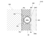
- the groove bottoms of the annular groove 55 and the side grooves 56 are along a cylindrical surface parallel to the outer circumferential surface 51b. That is, as shown in FIG. 5, the groove portion 54 has a groove bottom 54a that is parallel to the outer circumferential surface 51b. Further, the groove portion 54 has a groove wall 54b extending from the groove bottom 54a to the outer peripheral surface 51b.
- the first seal portion 50 has a function of sealing between the inner peripheral surface 51a of the first seal portion 50 and the outer diameter portion 32a of the rotor 30. Note that the sealing function of the first seal portion 50 prevents foreign matter from entering from outside of the region where the inner circumferential surface 51a of the first seal portion 50 and the outer diameter portion 32a of the rotor 30 face each other. It is preferable to act so as to suppress. The sealing function of the first seal portion 50 may not act to seal fluid flowing through the sealing structure 10.
- the second seal part 60 is arranged along the groove part 54 of the first seal part 50, as shown in FIG.
- the second seal portion 60 is separate from the first seal portion 50.
- the second seal portion 60 has an annular portion 67 and a bridging portion 68.
- the annular portion 67 corresponds to the pair of annular grooves 55 of the groove portion 54 .
- the bridging portion 68 corresponds to the side groove 56 of the groove portion 54.
- the bridging portion 68 spans between the pair of annular portions 67 .
- the second seal portion 60 has a function of sealing between the first seal portion 50 and the housing 20.
- the second seal portion 60 is made of elastomer such as synthetic rubber.
- the second seal portion 60 is preferably formed of ethylene propylene diene rubber (EDPM).
- the second seal portion 60 is made of an elastomer base material having a predetermined cross-sectional shape. Specifically, the second seal portion 60 has a shape in which the base material is continuously extended in a direction intersecting the cross section of the base material. That is, each of the annular portions 67 has a shape in which the cross section of the base material is continuously extended in an annular shape. Each of the bridging parts 68 has a shape in which the cross section of the base material is continuously extended along the central axis CA, with the direction intersecting the cross section of the base material being aligned with the central axis CA of the first sealing part 50. have
- the second seal portion 60 has a V-shaped cross section, as shown in FIG.
- the V-shaped cross section of the second seal portion 60 has a thickness.
- the second seal portion 60 is open toward the housing 20 side. That is, the second seal portion 60 has an opening 60a.
- the opening 60a opens toward the housing 20 side.
- the second seal portion 60 has two open ends 64 and a folded end 66 in cross-sectional view. Further, the second seal portion 60 has a bent portion 62 .
- the opening 60a extends continuously along the direction in which the cross section of the second seal portion 60 extends. That is, the opening 60a is along the direction in which the second seal portion 60 extends.
- the opening 60a is formed in a concave shape with respect to the outer periphery of the second seal portion 60 when viewed in cross section.
- the open end 64 is the open end of the opening 60a in cross-sectional view.
- the two open ends 64 of the annular portion 67 are aligned with each other along the axial direction of the first seal portion 50 .
- the two open ends 64 of the bridge portion 68 are aligned with each other along the circumferential direction of the first seal portion 50 .
- the folded end 66 is an end that is folded back into a V-shape in cross-sectional view.
- the second seal portion 60 is attached to the first seal portion 50 so that the folded end 66 is in contact with the groove bottom 54a.
- a gap S1 is formed between the second seal portion 60 and the groove wall 54b.
- a gap S1 is formed between the bent portion 62 of the second seal portion 60 and the groove portion 54.
- the second seal part 60 attached to the groove part 54 has an open end 64 projecting in the radial direction from the outer circumferential surface 51b of the first seal part 50.
- the second seal part 60 attached to the groove part 54 comes into contact with the housing 20 so that the open end 64 can fit into the inner circumferential surface 20b of the housing 20 during assembly.
- the open end 64 is an example of an outer end.
- the second seal part 60 seals between the first seal part 50 and the housing 20 by being pressed toward the groove bottom 54a by the housing 20.
- the second seal portion 60 surrounds the port portion 51p of the first seal portion 50 with the annular portion 67 and the bridging portion 68 when viewed from the radial direction.
- the annular portion 67 suppresses leakage of the fluid flowing between the port portion 51p of the first seal portion 50 and the port hole 20p of the housing 20 in the axial direction.
- the bridging portion 68 suppresses fluid leakage between adjacent port portions 51p or port holes 20p.
- the axial force applied from the first seal part 50 to the rotor 30 increases as the housing 20 presses the second seal part 60 against the groove bottom 54a.
- the bent portion 62 is a portion of the second seal portion 60 that extends from the two open ends 64 toward the folded end 66 .
- the bent portion 62 is configured to include the open end 64.
- the bent portion 62 is bent in a direction intersecting the radial direction of the first seal portion 50 when assembled with the housing 20 . That is, the bent portion 62 can be bent in a direction intersecting the radial direction of the first seal portion 50 during assembly.
- the second seal portion 60 can be bent in a direction intersecting the radial direction of the first seal portion 50 during assembly.
- the second seal portion 60 has a space 60b sandwiched between two open ends 64. The space 60b is adjacent to the bent portion 62 in cross-sectional view.
- the space 60b is located closer to the center of the cross section than the bent portion 62 when viewed in cross section.
- the bending of the bent portion 62 is preferably accompanied by elastic deformation in the axial direction.
- the bending of the bend 62 may be accompanied by volumetric compression of the elastomer.
- the first seal portion 50 is assembled to the rotor 30.
- the second seal part 60 is attached to the groove part 54 of the first seal part 50 assembled to the rotor 30.
- the sealing device 40 is assembled to the rotor 30.
- the housing 20 is assembled by moving the housing 20 toward the sealing device 40 from the outside in the axial direction (see FIG. 6). That is, the sealing device 40 is assembled by moving relatively from the outside to the inside of the housing 20 in the axial direction.
- the first open end 64 which is the side closer to the housing 20, comes into contact with the edge of the housing 20.
- a moment directed in the moving direction of the housing 20 is applied to the bent portion 62 including the first open end 64 in a cross-sectional view.
- a fitting force is applied to the second seal part 60 attached to the groove part 54 so that it is pressed from the housing 20 toward the groove bottom 54a.
- the bent portion 62 including the first open end 64 is bent in a direction intersecting the radial direction of the first seal portion 50.
- the bent portion 62 including the first open end 64 is bent so as to close the opening 60a.
- sealing structure 10H as a comparison form with respect to the first embodiment will be described using FIG. 7.
- the reference numerals and names of the parts will be used as they are.
- the comparative sealing structure 10H has a sealing device 40H instead of the sealing device 40 in the first embodiment.
- the sealing device 40H has a second seal portion 60H instead of the second seal portion 60, as shown in FIG.
- the second seal portion 60H has a solid circular cross section, as shown in FIG. 7(a). That is, the second seal portion 60H of the comparative embodiment does not have the opening 60a, the bent portion 62, and the open end 64. Further, the second seal portion 60H of the comparative embodiment does not have a structure that can be bent during assembly.
- the protrusion length of the second seal part 60H attached to the first seal part 50 from the outer circumferential surface 51b in the radial direction is the same as the protrusion length of the second seal part 60 of the first embodiment.
- the comparative sealing structure 10H has the same configuration as the sealing structure 10.
- the second seal portion 60H of the comparative embodiment attached to the groove portion 54 is elastically deformed so as to be compressed by the fitting force directed from the housing 20 toward the groove bottom 54a during assembly.
- the second seal part 60H attached to the first seal part 50 generates a reaction force according to the fitting force.
- the reaction force generated in the second seal portion 60H is an elastic force caused by the elastomer.
- the reaction force (elastic force) by the second seal portion 60H is transmitted to the first seal portion 50 in the radial direction toward the center axis CA, which is the same as the fitting force.
- the sealing device 40 has a bending portion 62 that can be bent in a direction intersecting the radial direction of the first sealing portion 50 when assembled. That is, the sealing device 40 has a second seal portion 60 that can be bent in a direction intersecting the radial direction of the first seal portion 50 when assembled.
- the reaction force (elastic force) generated in the second seal portion 60H in response to the fitting force from the housing 20 when the sealing structure 10 is assembled is smaller than that of the comparative sealing structure 10H (see FIG. 8). Therefore, by having the second seal part 60, the sealing device 40 reduces the radial component of the reaction force (elastic force) transmitted from the second seal part 60 to the first seal part 50 during assembly. be able to.
- the sealing structure 10 having the sealing device 40, the radial component of the reaction force (elastic force) transmitted from the second seal part 60 to the first seal part 50 becomes small, so that the first seal part 50 and the rotor 30 is smaller than that of the sealing structure 10H. Therefore, the sealing structure 10 can improve the assemblability of the sealing structure 10. In addition, the sealing structure 10 can improve the slidability of the rotor 30 by reducing the frictional force between the first seal portion 50 and the rotor 30. That is, when the sealing structure 10 is assembled by assembling the housing 20 after assembling the sealing device 40 to the rotor 30, it is possible to suppress deterioration of the slidability of the rotor 30 due to the assembling.
- the sealing structure 10 having the sealing device 40, the reaction force (elastic force) generated in the second seal part 60H in response to the fitting force from the housing 20 becomes small, so that the second seal part 60H and the housing 20 The frictional force between the sealing structure 10H and the sealing structure 10H is smaller than that of the sealing structure 10H. Therefore, the sealing structure 10 can further improve the assemblability of the sealing structure 10. That is, when the sealing structure 10 is assembled by assembling the housing 20 after assembling the sealing device 40 to the rotor 30, the ease of assembling the housing 20 can be improved.
- the bent portion 62 includes an open end 64 that contacts the housing 20 during assembly. Therefore, the bending portion 62 can be bent by a moment applied as a result of relative movement of the housing 20 from the outside to the inside in the axial direction during assembly. Therefore, the sealing device 40 can bend the second seal portion 60 more easily by further applying a fitting force from the housing 20 during assembly.
- the second seal portion 60 of the sealing device 40 has an opening 60a.
- the section modulus of the second seal part 60 becomes smaller, so the second seal part 60 becomes easier to bend. Therefore, when the sealing device 40 is assembled, the second seal portion 60 is easily bent.
- the bent portion 62 of the sealing device 40 can be bent to close the opening 60a during assembly.
- a sealing device A40 shown in FIG. 17 The sealing device A40 has a second sealing portion A60 instead of the second sealing portion 60 of the sealing device 40, as shown in FIG. 17(a).
- the second seal portion A60 has a V-shaped cross section that opens in the axial direction of the first seal portion 50.
- the second seal portion A60 has an opening A60a and an open end A64.
- the open end A64 on the housing 20 side comes into contact with the housing 20.
- the open end A64 on the housing 20 side is deformed along the moving direction of the housing 20, as shown in FIG. 17(b).
- the second seal portion A60 deforms so as to widen the opening portion A60a. If the second seal portion A60 is deformed to enlarge the opening A60a when the housing 20 is assembled, there is a possibility that the second seal portion A60 may turn over to the opening A60a side.
- the sealing device 40 can suppress the second seal portion 60 from turning over during assembly.
- the second seal portion 60 of the sealing device 40 has a V-shaped cross section. At this time, the second seal portion 60 is easily bent at a portion extending from the open end 64 to the folded end 66. Therefore, it is easy to identify the portion of the sealing device 40 that is bent during assembly.
- the opening 60a of the second seal portion 60 opens toward the housing 20 side. That is, in the second seal portion 60, the two open ends 64 are in contact with the housing 20. If the opening of the second seal portion having a V-shaped cross section opens toward the rotor 30 side, the second seal portion contacts the housing 20 at one folded end.
- the sealing performance between the second seal part and the housing 20 improves as the number of contact points between the second seal part and the housing 20 increases. Therefore, the sealing device 40 can improve the sealing performance between the second seal portion 60 and the housing 20 compared to the case where the opening is open toward the rotor 30 side.
- the second seal portion 60 of the sealing device 40 has open ends 64 that are aligned with each other along the axial direction. If the radial positions of the two open ends are misaligned, the frictional force between one open end and the housing 20 may be greater than the frictional force between the other open end and the housing 20 depending on the size of the misalignment. Since the size of the sealing device also increases, the ease of assembling the sealing device becomes difficult. On the other hand, when the two open ends 64 are lined up along the axial direction, the deviation in the radial position of the two open ends is small. Therefore, the difference in frictional force between each open end 64 and the housing 20 that occurs when the sealing device 40 is assembled becomes small. Therefore, the sealing device 40 can improve ease of assembly compared to a case where the two open ends 64 are misaligned in the radial direction.
- a gap S1 is formed between the groove portion 54 and the bent portion 62 of the sealing device 40. Therefore, when the bent portion 62 is bent in a cross-sectional view, it can be bent toward the gap S1. Therefore, the sealing device 40 can bend the second seal portion 60 toward the gap S1 during assembly.
- the second seal portion 60 is adjacent to the bent portion 62 in cross-sectional view, and has a space 60b provided closer to the center of the cross-section than the bent portion 62. Therefore, when the bent portion 62 is bent in a cross-sectional view, it can be bent toward the space 60b. Therefore, the sealing device 40 can bend the second seal portion 60 toward the space 60b during assembly.
- the sealing structure 10 may be assembled by assembling the sealing device 40 to the housing 20 and then assembling the rotor 30 to the inner peripheral surface 51a of the sealing device 40.
- the radial component of the reaction force (elastic force) transmitted from the second seal part 60 to the first seal part 50 is small, the radial direction component of the reaction force (elastic force) transmitted from the second seal part 60 to the first seal part 50 is small.
- the increase in force is smaller than that of the comparative sealing structure 10H. That is, in this case, the frictional force between the first seal portion 50 and the rotor 30 that occurs when the first seal portion 50 is assembled with the rotor 30 is smaller than that of the comparative sealing structure 10H. Therefore, when the sealing structure 10 is assembled by assembling the sealing device 40 to the housing 20 and then assembling the rotor 30 to the inner peripheral surface 51a of the sealing device 40, it is possible to improve the ease of assembling the rotor 30.
- the sealing structure 210 has a sealing device 240 instead of the sealing device 40 in the first embodiment, as shown in FIG. 9 .
- the sealing device 240 has a second seal portion 260 instead of the second seal portion 60 in the first embodiment.
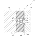
- the second seal portion 260 has a V-shaped cross section, as shown in FIG.
- the V-shaped cross section of the second seal portion 260 has a thickness.
- the cross section of the second seal portion 260 is open toward the rotor 30 side. That is, the second seal portion 260 has an opening 260a.
- the opening 260a opens toward the rotor 30 side.
- the second seal portion 260 has two open ends 264 and a folded end 266 in cross-sectional view. Further, the second seal portion 260 has a bent portion 262 .
- the second seal part 260 is attached to the first seal part 50 so that the two open ends 264 are in contact with the groove bottom 54a of the groove part 54. At this time, a gap S2 is formed between the second seal portion 260 and the groove wall 54b. In other words, a gap S2 is formed between the bent portion 262 and the groove portion 54.
- the second seal portion 260 mounted in the groove portion 54 brings the folded end 266 into contact with the housing 20 .
- the folded end 266 is an example of an outer end.
- the bent portion 262 includes a folded end 266.
- the second seal portion 260 has a space 260b sandwiched between two open ends 264.
- the space 260b is adjacent to the bent portion 262 in cross-sectional view.
- the space 260b is located closer to the center of the cross section than the bent portion 262 when viewed in cross section.
- the first seal portion 50 is assembled to the rotor 30.
- the second seal part 260 is attached to the groove part 54 of the first seal part 50 assembled to the rotor 30. That is, the sealing device 240 is assembled to the rotor 30.
- the housing 20 is assembled by moving the housing 20 relative to the sealing device 240 from the outside in the axial direction toward the sealing device 240 (see FIG. 10).
- the folded end 266 first comes into contact with the edge of the housing 20.
- a moment directed in the moving direction of the housing 20 is applied to the bent portion 262 including the folded end 266 in a cross-sectional view.
- a fitting force from the housing 20 toward the groove bottom 54a is applied to the second seal part 260 attached to the groove part 54.
- the first bent portion 262 which is on the housing 20 side with respect to the second seal portion 260 in the axial direction, is in a bent state.
- the sealing structure 210 has the same configuration as the sealing structure 10.
- the opening 260a of the second seal portion 260 opens toward the rotor 30 side. That is, in the second seal portion 260, one folded end 266 contacts the housing 20. Therefore, the frictional force generated between the second seal portion 260 and the housing 20 during assembly is smaller than that in the case where the opening is open toward the housing 20 side. Therefore, the sealing device 240 can improve ease of assembly compared to a case where the opening opens toward the housing 20 side.
- the sealing structure 310 has a sealing device 340 instead of the sealing device 40 in the first embodiment, as shown in FIG. 11 .
- the sealing device 340 has a second seal portion 360 instead of the second seal portion 60 in the first embodiment.
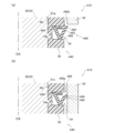
- the second seal portion 360 has a hollow annular cross section, as shown in FIG. 11 .
- the annular cross section of the second seal portion 360 has a thickness.
- the second seal portion 360 has an outer edge. Further, the second seal portion 360 has a bent portion 362 . Note that the second seal portion 360 does not have an opening in cross-sectional view.
- the second seal portion 360 has a space 360b inside its annular cross section.
- the space 360b is adjacent to the bent portion 362 in cross-sectional view.
- the space 360b is located closer to the center of the cross section than the bent portion 362 when viewed in cross section.
- the sealing structure 310 has the same configuration as the sealing structure 10.
- the sealing structure 310 and the sealing device 340 have the same effects as the sealing structure 10 and the sealing device 40, except for the effect due to the opening.
- the sealing structure 410 has a sealing device 440 instead of the sealing device 40 in the first embodiment, as shown in FIG. 12 .
- the sealing device 440 has a second seal portion 460 instead of the second seal portion 60 in the first embodiment.
- the second seal portion 460 has a C-shaped cross section, as shown in FIG. 12 .
- the C-shaped cross section of the second seal portion 460 has a thickness.
- the second seal portion 460 has an opening 460a.
- the opening 460a opens toward the groove wall 54b in cross-sectional view.
- the second seal portion 460 has two open ends 464 in cross-sectional view.
- the second seal portion 460 has a bent portion 462.
- the second seal portion 460 has an outer edge.
- the second seal portion 460 has a space 460b inside the C-shaped cross section.
- the space 460b is adjacent to the bent portion 462 in cross-sectional view.
- the space 460b is located closer to the center of the cross section than the bent portion 462 when viewed in cross section.
- the sealing structure 410 has the same configuration as the sealing structure 10.
- the sealing structure 410 and the sealing device 440 have the same effects as the sealing structure 210 and the sealing device 240.
- the sealing structure 510 has a sealing device 540 instead of the sealing device 40 in the first embodiment, as shown in FIG. 13.
- the sealing device 540 has a second seal portion 560 instead of the second seal portion 60 in the first embodiment.
- the second seal portion 560 has a substantially solid circular cross section, as shown in FIG.
- the second seal portion 560 has an opening 560a formed in a concave shape with respect to the outer periphery of the second seal portion 560 when viewed in cross section.
- the opening 560a is formed in a slit shape extending from the outer periphery of the cross section of the second seal portion 560 toward the center of the cross section.
- the opening 560a opens toward the groove wall 54b in cross-sectional view.
- the second seal portion 560 has two open ends 564 in cross-sectional view. Further, the second seal portion 560 has a bent portion 562.
- the bent portion 562 includes a portion where the distance between the inner part of the opening 560a and the outer circumference of the second seal portion 560 is the shortest in cross-sectional view.
- the second seal portion 560 has an outer edge. Except for the above points, the sealing structure 510 has the same configuration as the sealing structure 10.
- the sealing structure 510 and the sealing device 540 have the same effects as the sealing structure 210 and the sealing device 240.
- the sealing structure 610 has a sealing device 640 instead of the sealing device 40 in the first embodiment, as shown in FIG. 14 .
- the sealing device 640 has a first sealing portion 650 and a second sealing portion 660.
- the first seal portion 650 has a groove portion 654 instead of the groove portion 54 in the first embodiment.
- the groove portion 654 is formed in a V-shape when viewed in cross section.
- the groove portion 654 has a rear end portion 654a and a pair of inclined surfaces 654b.
- the rear end portion 654a is an end portion that is bent in a V-shape when viewed in cross section.
- the pair of inclined surfaces 654b are open toward the housing 20 side.
- Each inclined surface 654b is inclined linearly in a direction intersecting the radial direction when viewed in cross section.
- the pair of inclined surfaces 654b have symmetry in the radial direction of the first seal portion 650.
- the second seal portion 660 has a substantially solid circular cross section, as shown in FIG. That is, the second seal portion 660 does not have an opening, a bent portion, and an open end. Further, the second seal portion 660 does not have a structure that can be bent during assembly.
- the second seal portion 660 is attached to the first seal portion 650 while contacting the pair of inclined surfaces 654b of the groove portion 654.
- a gap S6 is formed between the second seal portion 660 and the inner end portion 654a.
- the sealing structure 610 has the same configuration as the sealing structure 10.
- the second seal part 660 attached to the first seal part 650 generates a reaction force (elastic force) according to the fitting force applied from the housing 20 during assembly.
- the second seal portion 660 comes into contact with the pair of inclined surfaces 654b. Therefore, the reaction force (elastic force) generated in the second seal portion 660 is directed toward the first seal via the groove portion 654 in a direction opposite to the normal direction of each of the pair of inclined surfaces 654b. 650.
- the radial component of the reaction force (elastic force) transmitted from the second seal part 660 to the first seal part 650 when the seal structure 610 is assembled becomes smaller than that of the comparative seal structure 10H. Therefore, by having the groove portion 654, the sealing device 640 can reduce the radial component of the reaction force (elastic force) transmitted from the second seal portion 660 to the first seal portion 650 during assembly.
- sealing structure 610 including the sealing device 640 can have the same effects as the sealing structure 10.
- a gap S6 is formed between the rear end portion 654a and the second seal portion 660 when not assembled.
- the second seal part 660 exhibits behavior peculiar to the elastomer so as to make the area of the gap S6 smaller than when it is not pressed by the housing 20. Transform towards S6. That is, the second seal portion 660 can be deformed toward the gap S6 during assembly.
- the sealing device 640 can reduce the reaction force (elastic force) generated in the second seal portion 60 due to the pressing from the housing 20 during assembly.
- the pair of inclined surfaces 654b have symmetry in the radial direction of the first seal portion 650. At this time, the forces generated between the pair of inclined surfaces 654b and the second seal portion 660 during assembly cancel each other out in the axial direction. Therefore, the second seal portion 660 is difficult to shift from the groove portion 654 in the axial direction during assembly. Therefore, the sealing device 640 can improve ease of assembly.
- the sealing structure 710 has a sealing device 740 instead of the sealing device 40 in the first embodiment, as shown in FIG. 15 .
- the sealing device 740 has a first seal portion 750 instead of the first seal portion 50 in the first embodiment.
- the sealing device 740 includes the second seal portion 60 in the first embodiment. That is, the second seal portion 60 of the sealing device 740 has a bent portion 62 that can be bent during assembly. Additionally, the second seal portion 60 of the sealing device 740 has a folded end 66 .
- the sealing device 740 may have any of the second seal parts 260, 360, 460, and 560 instead of the second seal part 60.
- the first seal portion 750 has a groove portion 754 instead of the groove portion 54 in the first embodiment.
- the groove 754 is similar to the groove 654 in the sixth embodiment. That is, as shown in FIG. 15, the groove portion 754 is formed in a V-shape when viewed in cross section.
- the groove portion 754 has a rear end portion 754a and a pair of inclined surfaces 754b.
- the pair of inclined surfaces 754b are open toward the housing 20 side.
- Each inclined surface 754b is inclined linearly in a direction intersecting the radial direction in cross-sectional view.
- the pair of inclined surfaces 754b have symmetry in the radial direction of the first seal portion 750.
- the second seal portion 60 is attached to the first seal portion 750 while contacting the pair of inclined surfaces 754b of the groove portion 754.
- the second seal part 60 is attached to the first seal part 750 so that the folded end 66 contacts the pair of inclined surfaces 754b. At this time, a gap S7 is formed between the bent portion 62 and the pair of inclined surfaces 754b.
- the sealing structure 610 has the same configuration as the sealing structure 10.
- the second seal portion 60 of the sealing device 740 has a bent portion 62 that can be bent during assembly. Therefore, the sealing device 740 can further reduce the amount of deformation of the first seal portion 750 during assembly.
- a gap S7 is formed between the groove portion 754 of the sealing device 740 and the bent portion 62. Therefore, the bent portion 62 can be bent toward the gap S7. Therefore, in the sealing device 740, when the second seal part 60 is attached to the groove part 754 having the pair of inclined surfaces 754b, the second seal part 60 cannot be bent toward the gap S7 during assembly. can.
- the opening of the second seal may extend in the radial or axial direction of the first seal.
- the opening was made in the direction along the line.
- the opening of the second seal part according to the present disclosure may be opened in a direction inclined with respect to the radial direction and/or the axial direction of the first seal part.
- the groove portions 654 and 754 in the sixth embodiment and the seventh embodiment are formed in a V-shape in cross-sectional view.
- the groove portion having a pair of inclined surfaces according to the present disclosure further includes a groove bottom sandwiched between the pair of inclined surfaces and parallel to the outer circumferential surface of the first seal portion. Good too.
- the first seal portion 50 of the first embodiment extends from the cylindrical outer peripheral surface 51b to the groove wall 54b.
- the first seal portion 50 may have a protrusion 57 around the groove portion 54, as shown in FIG. 16.
- the protrusion 57 is formed in a rib shape along the groove portion 54. That is, the first seal portion according to the present disclosure may have a rib-shaped protrusion around the groove portion.
- the second seal portion 60 of the first embodiment is bent so as to close the opening 60a.
- the second seal portion of the sealing device according to the present disclosure may be bent to open the opening.
- the sealing device according to the present disclosure may be, for example, the sealing device A40 described above (see FIG. 17).
- the second seal portion according to the present disclosure may be a second seal portion 860 having a spiral cross-sectional shape, as shown in FIG. 18 .
- the second seal portion 860 has a buckling portion 862, a space 860a, and an opening 860b.
- the second seal portion 60 of the first embodiment may be configured such that the open end 64 is bent toward the space 60b, as shown in FIG. 19(b). Specifically, as shown in FIG.
- the second seal portion 60 has a cut 69 in a part of the space 60b side extending from the folded end 66 to the open end 64 in a cross-sectional view. may have.
- the second seal portion 60 may have a crease instead of the cut 69. It is preferable that the cut 69 or the fold line extends along the direction in which the cross section of the second seal portion 60 extends. The cut 69 or the fold may extend linearly so as to intersect with the direction in which the cross section of the second seal portion 60 extends.
- CA Central axis 10: Sealing structure 20: Housing 20b: Inner circumferential surface 30: Rotor 40: Sealing device 50: First seal portion 51: Main body portion 51p: Port portion 51b: Outer circumferential surface 51a: Inner circumferential surface 54: Groove portion 54a : Groove bottom 60 : Second seal part 60a : Opening part 62 : Bent part 64 : Open end S1 : Gap 210 : Sealing structure 240 : Sealing device 260 : Second seal part 260a : Opening part 262 : Bent part 264 : Open end S2 : Gap 310 : Sealing structure 340 : Sealing device 360 : Second seal part 362 : Bent part 410 : Sealing structure 440 : Sealing device 460 : Second seal part 460a : Opening part 462 : Bent part 464 : Open end 510: Sealing structure 540: Sealing device 560: Second seal portion 560a: Opening portion 562: Bent portion 564:
Abstract
A sealing device 40 that is assembled between a cylindrical housing 20 and a rotor 30 that is arranged coaxially inside the housing 20 and rotates about an axis, the sealing device 40 comprising: a first seal part 50 having a main body portion 51 along an outer diameter portion 32a of the rotor 30, the first sealing part 50 including a port portion 51p that penetrates the main body portion 51 in the radial direction, and a groove portion 54 formed in an outer peripheral surface 51b of the main body portion 51, the groove portion 54 having a groove bottom 54a parallel to the outer peripheral surface 51b and being formed so as to surround the port portion 51p when viewed from the radial outer circumferential surface 51b side; and a second seal part 60 that is mounted on the groove portion 54 so as to be in contact with the groove bottom 54a and seals between the housing 20 and the first seal part 50, the second seal part 60 having a bending portion 62 that can be bent during assembly.
Description
本開示は、密封装置、密封構造、密封構造の組み付け方法に関する。
The present disclosure relates to a sealing device, a sealing structure, and a method of assembling the sealing structure.
1つの機械システムに設けられた複数の流路を流れる流体の流通状態を切り替える装置として、ロータリー型の弁装置が知られている。例えば、図1に示される電気自動車の熱マネジメントシステムTMは、冷却液が流れる4つの循環流路CF1,CF2,CF3,CF4と、ロータリー型の弁装置の一例としての多ポート弁V10と、を有する。
循環流路CF1は、バッテリー部BTのまわりに設けられている。循環流路CF2は、熱交換器R1のまわりに設けられており、ポンプP1を有する。循環流路CF3は、熱交換器R2及びコンデンサC2のまわりに設けられており、タンクRTを有する。循環流路CF4は、電子部品ED及びアクスルAXのまわりに設けられており、ポンプP2を有する。 A rotary valve device is known as a device that switches the flow state of fluid flowing through a plurality of channels provided in one mechanical system. For example, the electric vehicle thermal management system TM shown in FIG. 1 includes four circulation channels CF1, CF2, CF3, and CF4 through which coolant flows, and a multi-port valve V10 as an example of a rotary type valve device. have
The circulation flow path CF1 is provided around the battery part BT. The circulation channel CF2 is provided around the heat exchanger R1 and includes a pump P1. The circulation flow path CF3 is provided around the heat exchanger R2 and the condenser C2, and has a tank RT. The circulation channel CF4 is provided around the electronic component ED and the axle AX, and includes a pump P2.
多ポート弁V10は、各循環流路CF1~4を互いに合流可能に設けられる。多ポート弁V10は、ハウジングV2と、ロータV3と、密封装置V4と、を有する。ハウジングV2は、各循環流路CF1~4と接続する複数のポート部V2aを有する。
ロータV3は、ハウジングV2の内側で中心軸OVまわりに回転可能に設けられる。ロータV3は、ポート部V2aと接続可能な複数のポート部V3aと、複数のポート部V3aのうち2つのポート部V3aを接続する複数の流路V3bと、を有する。
密封装置V4は、ポート部V2aとポート部V3aとの間で冷却液を流通可能な状態で、ハウジングV2とロータV3との間をシールする。
ロータV3を回転させることで、多ポート弁V10は、循環流路CF1~4の相互の接続状態及び循環流路CF1~4を流れる冷却液の流通状態を切り替える。なお、熱交換器R2及びコンデンサC2のまわりには、エバポレータERと、アキュムレータARと、コンプレッサCPと、コンデンサC1と、を有する他の循環流路が設けられている。 The multi-port valve V10 is provided so that the circulation channels CF1 to CF4 can merge with each other. Multiport valve V10 has a housing V2, a rotor V3, and a sealing device V4. The housing V2 has a plurality of port portions V2a connected to each of the circulation channels CF1 to CF4.
The rotor V3 is rotatably provided inside the housing V2 around the central axis OV. The rotor V3 includes a plurality of port sections V3a that can be connected to the port section V2a, and a plurality of flow paths V3b that connect two port sections V3a among the plurality of port sections V3a.
The sealing device V4 seals between the housing V2 and the rotor V3 in a state where the coolant can flow between the port portion V2a and the port portion V3a.
By rotating the rotor V3, the multi-port valve V10 switches the mutual connection state of the circulation channels CF1 to CF4 and the flow state of the coolant flowing through the circulation channels CF1 to CF4. Note that another circulation flow path including an evaporator ER, an accumulator AR, a compressor CP, and a condenser C1 is provided around the heat exchanger R2 and the condenser C2.
ロータリー型の弁装置の構造として、特開2018-96543号公報(以下、特許文献1)に記載されるような、弁室を有する弁本体(すなわち、ハウジング)と、弁室内に配置されて弁軸を介して回転する弁体(すなわち、ロータ)と、弁体と弁本体との間に配置されるシール部材であって、円筒体(すなわち、第1のシール部)と、外側リブ(すなわち、第2のシール部)と、を有するシール部材と、を有するものが知られている。
The structure of a rotary type valve device includes a valve body (i.e., a housing) having a valve chamber, and a valve body disposed inside the valve chamber, as described in Japanese Patent Application Laid-Open No. 2018-96543 (hereinafter referred to as Patent Document 1). A valve body (i.e., a rotor) that rotates through a shaft, a sealing member disposed between the valve body and the valve body, the sealing member having a cylindrical body (i.e., a first sealing portion) and an outer rib (i.e., , a second seal portion), and a seal member having a second seal portion) are known.
特許文献1に記載されるシール部材は、円筒体と外側リブとが一体に成形されており、合成ゴム等の弾性材料から形成されている。弾性材料から形成された外側リブは、中実断面を有する。外側リブは、弁装置として組み込まれるときに弁本体から付与されて円筒体の中心軸方向に向かう嵌合力に応じた反力を発生させて円筒体に伝達させる。外側リブに発生する反力は、弾性材料に起因する弾性力である。外側リブによる反力は、円筒体に対して嵌合力と同じ方向に向けて作用し、円筒体の内周部による軸方向への力を増加させる。円筒体の内周部は弁体と接触しているため、円筒体による力の増加は、シール部材の弁体に対する摺動性を悪化させる虞がある。また、円筒体による力が増加すると、弁装置におけるシール部材の組み付け性を悪化させる虞がある。
The sealing member described in Patent Document 1 has a cylindrical body and an outer rib that are integrally molded, and is made of an elastic material such as synthetic rubber. The outer ribs formed from a resilient material have a solid cross section. The outer rib generates a reaction force corresponding to a fitting force applied from the valve body toward the central axis of the cylindrical body when assembled as a valve device, and transmits the reaction force to the cylindrical body. The reaction force generated on the outer rib is an elastic force caused by the elastic material. The reaction force exerted by the outer rib acts on the cylindrical body in the same direction as the fitting force, increasing the axial force exerted by the inner periphery of the cylindrical body. Since the inner periphery of the cylindrical body is in contact with the valve body, an increase in the force exerted by the cylindrical body may deteriorate the slidability of the sealing member with respect to the valve body. Moreover, if the force exerted by the cylindrical body increases, there is a possibility that the ease of assembling the seal member in the valve device may be deteriorated.
本開示は、組み付け時に第2のシール部から第1のシール部に伝達される反力の径方向成分を小さくすることを目的とする。
The present disclosure aims to reduce the radial component of the reaction force transmitted from the second seal portion to the first seal portion during assembly.
本開示の第1の態様は、円筒状のハウジングと、前記ハウジングの内側で同軸状に配置されて軸回りに回転するロータとの間に組み付けられる密封装置である。当該密封装置は、
前記ロータの外径部に沿う本体部を有する第1のシール部であって、
前記本体部を径方向に貫通するポート部と、
前記本体部の外周面に形成された溝部であって、前記外周面に平行な溝底を有し、前記径方向の前記外周面側から見て前記ポート部のまわりを囲むように形成された溝部と、
を有する第1のシール部と、
前記溝底と接触するように前記溝部に装着されて、前記ハウジングと前記第1のシール部との間をシールする第2のシール部であって、組み付け時に屈曲可能な屈曲部を有する第2のシール部と、
を有する。
本開示の第2の態様は、円筒状のハウジングと、前記ハウジングの内側で同軸状に配置されて軸回りに回転するロータとの間に組み付けられる密封装置である。当該密封装置は、
前記ロータの外径部に沿う本体部を有する第1のシール部であって、
前記本体部を径方向に貫通するポート部と、
前記本体部の外周面に形成された溝部であって、前記外周面に平行な溝底を有し、前記径方向の前記外周面側から見て前記ポート部のまわりを囲むように形成された溝部と、
を有する第1のシール部と、
前記溝底と接触するように前記溝部に装着されて、前記ハウジングと前記第1のシール部との間をシールする第2のシール部であって、組み付け時に前記径方向と交差する方向に屈曲可能な屈曲部を有する第2のシール部と、
を有する。 A first aspect of the present disclosure is a sealing device assembled between a cylindrical housing and a rotor that is coaxially arranged inside the housing and rotates about an axis. The sealing device is
A first seal portion having a main body portion along an outer diameter portion of the rotor,
a port portion that penetrates the main body portion in a radial direction;
A groove portion formed on the outer peripheral surface of the main body portion, the groove portion having a groove bottom parallel to the outer peripheral surface, and formed to surround the port portion when viewed from the outer peripheral surface side in the radial direction. A groove and
a first seal portion having a
a second seal part that is attached to the groove part so as to be in contact with the groove bottom and seals between the housing and the first seal part, the second seal part having a bent part that can be bent during assembly; The seal part of
has.
A second aspect of the present disclosure is a sealing device assembled between a cylindrical housing and a rotor that is coaxially arranged inside the housing and rotates about an axis. The sealing device is
A first seal portion having a main body portion along an outer diameter portion of the rotor,
a port portion that penetrates the main body portion in a radial direction;
A groove portion formed on the outer peripheral surface of the main body portion, the groove portion having a groove bottom parallel to the outer peripheral surface, and formed to surround the port portion when viewed from the outer peripheral surface side in the radial direction. A groove and
a first seal portion having a
a second seal part that is attached to the groove part so as to be in contact with the groove bottom and seals between the housing and the first seal part, the second seal part being bent in a direction intersecting the radial direction when assembled; a second seal portion having a possible bend;
has.
前記ロータの外径部に沿う本体部を有する第1のシール部であって、
前記本体部を径方向に貫通するポート部と、
前記本体部の外周面に形成された溝部であって、前記外周面に平行な溝底を有し、前記径方向の前記外周面側から見て前記ポート部のまわりを囲むように形成された溝部と、
を有する第1のシール部と、
前記溝底と接触するように前記溝部に装着されて、前記ハウジングと前記第1のシール部との間をシールする第2のシール部であって、組み付け時に屈曲可能な屈曲部を有する第2のシール部と、
を有する。
本開示の第2の態様は、円筒状のハウジングと、前記ハウジングの内側で同軸状に配置されて軸回りに回転するロータとの間に組み付けられる密封装置である。当該密封装置は、
前記ロータの外径部に沿う本体部を有する第1のシール部であって、
前記本体部を径方向に貫通するポート部と、
前記本体部の外周面に形成された溝部であって、前記外周面に平行な溝底を有し、前記径方向の前記外周面側から見て前記ポート部のまわりを囲むように形成された溝部と、
を有する第1のシール部と、
前記溝底と接触するように前記溝部に装着されて、前記ハウジングと前記第1のシール部との間をシールする第2のシール部であって、組み付け時に前記径方向と交差する方向に屈曲可能な屈曲部を有する第2のシール部と、
を有する。 A first aspect of the present disclosure is a sealing device assembled between a cylindrical housing and a rotor that is coaxially arranged inside the housing and rotates about an axis. The sealing device is
A first seal portion having a main body portion along an outer diameter portion of the rotor,
a port portion that penetrates the main body portion in a radial direction;
A groove portion formed on the outer peripheral surface of the main body portion, the groove portion having a groove bottom parallel to the outer peripheral surface, and formed to surround the port portion when viewed from the outer peripheral surface side in the radial direction. A groove and
a first seal portion having a
a second seal part that is attached to the groove part so as to be in contact with the groove bottom and seals between the housing and the first seal part, the second seal part having a bent part that can be bent during assembly; The seal part of
has.
A second aspect of the present disclosure is a sealing device assembled between a cylindrical housing and a rotor that is coaxially arranged inside the housing and rotates about an axis. The sealing device is
A first seal portion having a main body portion along an outer diameter portion of the rotor,
a port portion that penetrates the main body portion in a radial direction;
A groove portion formed on the outer peripheral surface of the main body portion, the groove portion having a groove bottom parallel to the outer peripheral surface, and formed to surround the port portion when viewed from the outer peripheral surface side in the radial direction. A groove and
a first seal portion having a
a second seal part that is attached to the groove part so as to be in contact with the groove bottom and seals between the housing and the first seal part, the second seal part being bent in a direction intersecting the radial direction when assembled; a second seal portion having a possible bend;
has.
本開示の第3の態様は、円筒状のハウジングと、前記ハウジングの内側で同軸状に配置されて軸回りに回転するロータとの間に組み付けられる密封装置である。当該密封装置は、
前記ロータの外径部に沿う本体部を有する第1のシール部であって、
前記本体部を径方向に貫通するポート部と、
前記本体部の外周面に形成された溝部であって、前記外周面に平行な溝底を有し、前記径方向の前記外周面側から見て前記ポート部のまわりを囲むように形成された溝部と、
を有する第1のシール部と、
前記溝底と接触するように前記溝部に装着されて、前記ハウジングと前記第1のシール部との間をシールする第2のシール部であって、組み付け時に屈曲可能な第2のシール部と、
を有する。
本開示の第4の態様は、円筒状のハウジングと、前記ハウジングの内側で同軸状に配置されて軸回りに回転するロータとの間に組み付けられる密封装置である。当該密封装置は、
前記ロータの外径部に沿う本体部を有する第1のシール部であって、
前記本体部を径方向に貫通するポート部と、
前記本体部の外周面に形成された溝部であって、前記外周面に平行な溝底を有し、前記径方向の前記外周面側から見て前記ポート部のまわりを囲むように形成された溝部と、
を有する第1のシール部と、
前記溝底と接触するように前記溝部に装着されて、前記ハウジングと前記第1のシール部との間をシールする第2のシール部であって、組み付け時に前記径方向と交差する方向に屈曲可能な第2のシール部と、
を有する。 A third aspect of the present disclosure is a sealing device assembled between a cylindrical housing and a rotor that is coaxially arranged inside the housing and rotates around an axis. The sealing device is
A first seal portion having a main body portion along an outer diameter portion of the rotor,
a port portion that penetrates the main body portion in a radial direction;
A groove portion formed on the outer peripheral surface of the main body portion, the groove portion having a groove bottom parallel to the outer peripheral surface, and formed to surround the port portion when viewed from the outer peripheral surface side in the radial direction. A groove and
a first seal portion having a
a second seal part that is attached to the groove part so as to be in contact with the groove bottom and seals between the housing and the first seal part, the second seal part being bendable during assembly; ,
has.
A fourth aspect of the present disclosure is a sealing device assembled between a cylindrical housing and a rotor that is coaxially arranged inside the housing and rotates about an axis. The sealing device is
A first seal portion having a main body portion along an outer diameter portion of the rotor,
a port portion that penetrates the main body portion in a radial direction;
A groove portion formed on the outer peripheral surface of the main body portion, the groove portion having a groove bottom parallel to the outer peripheral surface, and formed to surround the port portion when viewed from the outer peripheral surface side in the radial direction. A groove and
a first seal portion having a
a second seal part that is attached to the groove part so as to be in contact with the groove bottom and seals between the housing and the first seal part, the second seal part being bent in a direction intersecting the radial direction when assembled; a possible second seal portion;
has.
前記ロータの外径部に沿う本体部を有する第1のシール部であって、
前記本体部を径方向に貫通するポート部と、
前記本体部の外周面に形成された溝部であって、前記外周面に平行な溝底を有し、前記径方向の前記外周面側から見て前記ポート部のまわりを囲むように形成された溝部と、
を有する第1のシール部と、
前記溝底と接触するように前記溝部に装着されて、前記ハウジングと前記第1のシール部との間をシールする第2のシール部であって、組み付け時に屈曲可能な第2のシール部と、
を有する。
本開示の第4の態様は、円筒状のハウジングと、前記ハウジングの内側で同軸状に配置されて軸回りに回転するロータとの間に組み付けられる密封装置である。当該密封装置は、
前記ロータの外径部に沿う本体部を有する第1のシール部であって、
前記本体部を径方向に貫通するポート部と、
前記本体部の外周面に形成された溝部であって、前記外周面に平行な溝底を有し、前記径方向の前記外周面側から見て前記ポート部のまわりを囲むように形成された溝部と、
を有する第1のシール部と、
前記溝底と接触するように前記溝部に装着されて、前記ハウジングと前記第1のシール部との間をシールする第2のシール部であって、組み付け時に前記径方向と交差する方向に屈曲可能な第2のシール部と、
を有する。 A third aspect of the present disclosure is a sealing device assembled between a cylindrical housing and a rotor that is coaxially arranged inside the housing and rotates around an axis. The sealing device is
A first seal portion having a main body portion along an outer diameter portion of the rotor,
a port portion that penetrates the main body portion in a radial direction;
A groove portion formed on the outer peripheral surface of the main body portion, the groove portion having a groove bottom parallel to the outer peripheral surface, and formed to surround the port portion when viewed from the outer peripheral surface side in the radial direction. A groove and
a first seal portion having a
a second seal part that is attached to the groove part so as to be in contact with the groove bottom and seals between the housing and the first seal part, the second seal part being bendable during assembly; ,
has.
A fourth aspect of the present disclosure is a sealing device assembled between a cylindrical housing and a rotor that is coaxially arranged inside the housing and rotates about an axis. The sealing device is
A first seal portion having a main body portion along an outer diameter portion of the rotor,
a port portion that penetrates the main body portion in a radial direction;
A groove portion formed on the outer peripheral surface of the main body portion, the groove portion having a groove bottom parallel to the outer peripheral surface, and formed to surround the port portion when viewed from the outer peripheral surface side in the radial direction. A groove and
a first seal portion having a
a second seal part that is attached to the groove part so as to be in contact with the groove bottom and seals between the housing and the first seal part, the second seal part being bent in a direction intersecting the radial direction when assembled; a possible second seal portion;
has.
本開示の第5の態様は、密封構造である。当該密封構造は、
円筒状のハウジングと、
前記ハウジングの内側で同軸状に配置されて軸回りに回転するロータと、
前記ロータの外径部に沿う本体部を有する第1のシール部であって、
前記本体部を径方向に貫通するポート部と、
前記本体部の外周面に形成された溝部であって、前記外周面に平行な溝底を有し、前記径方向の前記外周面側から見て前記ポート部のまわりを囲むように形成された溝部と、
を有する第1のシール部と、
前記溝底と接触するように前記溝部に装着されて、前記ハウジングと前記第1のシール部との間を屈曲した状態でシールする第2のシール部と、
を有する。
本開示の第6の態様は、密封構造である。当該密封構造は、
円筒状のハウジングと、
前記ハウジングの内側で同軸状に配置されて軸回りに回転するロータと、
前記ロータの外径部に沿う本体部を有する第1のシール部であって、
前記本体部を径方向に貫通するポート部と、
前記本体部の外周面に形成された溝部であって、前記外周面に平行な溝底を有し、前記径方向の前記外周面側から見て前記ポート部のまわりを囲むように形成された溝部と、
を有する第1のシール部と、
前記溝底と接触するように前記溝部に装着されて、前記ハウジングと前記第1のシール部との間を前記径方向と交差する方向に屈曲した状態でシールする第2のシール部と、
を有する。 A fifth aspect of the present disclosure is a sealed structure. The sealed structure is
a cylindrical housing;
a rotor that is coaxially arranged inside the housing and rotates about an axis;
A first seal portion having a main body portion along an outer diameter portion of the rotor,
a port portion that penetrates the main body portion in a radial direction;
A groove portion formed on the outer peripheral surface of the main body portion, the groove portion having a groove bottom parallel to the outer peripheral surface, and formed to surround the port portion when viewed from the outer peripheral surface side in the radial direction. A groove and
a first seal portion having a
a second seal part that is attached to the groove part so as to be in contact with the groove bottom and seals between the housing and the first seal part in a bent state;
has.
A sixth aspect of the present disclosure is a sealed structure. The sealed structure is
a cylindrical housing;
a rotor that is coaxially arranged inside the housing and rotates about an axis;
A first seal portion having a main body portion along an outer diameter portion of the rotor,
a port portion that penetrates the main body portion in a radial direction;
A groove portion formed on the outer peripheral surface of the main body portion, the groove portion having a groove bottom parallel to the outer peripheral surface, and formed to surround the port portion when viewed from the outer peripheral surface side in the radial direction. A groove and
a first seal portion having a
a second seal part that is attached to the groove part so as to be in contact with the groove bottom and seals between the housing and the first seal part in a bent state in a direction intersecting the radial direction;
has.
円筒状のハウジングと、
前記ハウジングの内側で同軸状に配置されて軸回りに回転するロータと、
前記ロータの外径部に沿う本体部を有する第1のシール部であって、
前記本体部を径方向に貫通するポート部と、
前記本体部の外周面に形成された溝部であって、前記外周面に平行な溝底を有し、前記径方向の前記外周面側から見て前記ポート部のまわりを囲むように形成された溝部と、
を有する第1のシール部と、
前記溝底と接触するように前記溝部に装着されて、前記ハウジングと前記第1のシール部との間を屈曲した状態でシールする第2のシール部と、
を有する。
本開示の第6の態様は、密封構造である。当該密封構造は、
円筒状のハウジングと、
前記ハウジングの内側で同軸状に配置されて軸回りに回転するロータと、
前記ロータの外径部に沿う本体部を有する第1のシール部であって、
前記本体部を径方向に貫通するポート部と、
前記本体部の外周面に形成された溝部であって、前記外周面に平行な溝底を有し、前記径方向の前記外周面側から見て前記ポート部のまわりを囲むように形成された溝部と、
を有する第1のシール部と、
前記溝底と接触するように前記溝部に装着されて、前記ハウジングと前記第1のシール部との間を前記径方向と交差する方向に屈曲した状態でシールする第2のシール部と、
を有する。 A fifth aspect of the present disclosure is a sealed structure. The sealed structure is
a cylindrical housing;
a rotor that is coaxially arranged inside the housing and rotates about an axis;
A first seal portion having a main body portion along an outer diameter portion of the rotor,
a port portion that penetrates the main body portion in a radial direction;
A groove portion formed on the outer peripheral surface of the main body portion, the groove portion having a groove bottom parallel to the outer peripheral surface, and formed to surround the port portion when viewed from the outer peripheral surface side in the radial direction. A groove and
a first seal portion having a
a second seal part that is attached to the groove part so as to be in contact with the groove bottom and seals between the housing and the first seal part in a bent state;
has.
A sixth aspect of the present disclosure is a sealed structure. The sealed structure is
a cylindrical housing;
a rotor that is coaxially arranged inside the housing and rotates about an axis;
A first seal portion having a main body portion along an outer diameter portion of the rotor,
a port portion that penetrates the main body portion in a radial direction;
A groove portion formed on the outer peripheral surface of the main body portion, the groove portion having a groove bottom parallel to the outer peripheral surface, and formed to surround the port portion when viewed from the outer peripheral surface side in the radial direction. A groove and
a first seal portion having a
a second seal part that is attached to the groove part so as to be in contact with the groove bottom and seals between the housing and the first seal part in a bent state in a direction intersecting the radial direction;
has.
本開示の第7の態様は、円筒状のハウジングと、前記ハウジングの内側で同軸状に配置されて軸回りに回転するロータとの間に組み付けられる密封装置である。当該密封装置は、
前記ロータの外径部に沿う本体部を有する第1のシール部であって、
前記本体部を径方向に貫通するポート部と、
前記径方向の前記外周面側から見て前記ポート部のまわりを囲むように前記本体部の外周面に形成された溝部であって、前記ハウジング側に向けて開く1対の傾斜面を有する溝部と、
を有する第1のシール部と、
前記溝部に装着されて、前記ハウジングと前記第1のシール部との間をシールする第2のシール部であって、前記1対の傾斜面と接触する第2のシール部と、
を有する。
本開示の第8の態様は、円筒状のハウジングと、前記ハウジングの内側で同軸状に配置されて軸回りに回転するロータとの間に組み付けられる密封装置である。当該密封装置は、
前記ロータの外径部に沿う本体部を有する第1のシール部であって、
前記本体部を径方向に貫通するポート部と、
前記径方向の前記外周面側から見て前記ポート部のまわりを囲むように前記本体部の外周面に形成された溝部であって、断面視で前記径方向に対して交差する方向で直線状に傾斜している1対の傾斜面と、溝奥と、を有する溝部と、
を有する第1のシール部と、
前記溝部に装着されて、前記ハウジングと前記第1のシール部との間をシールする第2のシール部であって、前記1対の傾斜面と接触する第2のシール部と、
を有し、
前記溝奥は、前記第2のシール部との間に第1の間隙を形成し、
第2のシール部は、組み付け時に前記第1の間隙に向けて変形可能である。 A seventh aspect of the present disclosure is a sealing device assembled between a cylindrical housing and a rotor that is coaxially arranged inside the housing and rotates about an axis. The sealing device is
A first seal portion having a main body portion along an outer diameter portion of the rotor,
a port portion that penetrates the main body portion in a radial direction;
A groove formed in the outer circumferential surface of the main body portion so as to surround the port portion when viewed from the outer circumferential surface side in the radial direction, the groove portion having a pair of inclined surfaces that open toward the housing side. and,
a first seal portion having a
a second seal part that is attached to the groove part and seals between the housing and the first seal part, the second seal part being in contact with the pair of inclined surfaces;
has.
An eighth aspect of the present disclosure is a sealing device assembled between a cylindrical housing and a rotor that is coaxially arranged inside the housing and rotates about an axis. The sealing device is
A first seal portion having a main body portion along an outer diameter portion of the rotor,
a port portion that penetrates the main body portion in a radial direction;
A groove formed in the outer circumferential surface of the main body section so as to surround the port section when viewed from the outer circumferential surface side in the radial direction, the groove section being linear in a direction intersecting the radial direction when viewed in cross section. a groove portion having a pair of sloped surfaces that are sloped at a distance, and a groove depth;
a first seal portion having a
a second seal part that is attached to the groove part and seals between the housing and the first seal part, the second seal part being in contact with the pair of inclined surfaces;
has
The inner part of the groove forms a first gap with the second seal part,
The second seal portion is deformable toward the first gap during assembly.
前記ロータの外径部に沿う本体部を有する第1のシール部であって、
前記本体部を径方向に貫通するポート部と、
前記径方向の前記外周面側から見て前記ポート部のまわりを囲むように前記本体部の外周面に形成された溝部であって、前記ハウジング側に向けて開く1対の傾斜面を有する溝部と、
を有する第1のシール部と、
前記溝部に装着されて、前記ハウジングと前記第1のシール部との間をシールする第2のシール部であって、前記1対の傾斜面と接触する第2のシール部と、
を有する。
本開示の第8の態様は、円筒状のハウジングと、前記ハウジングの内側で同軸状に配置されて軸回りに回転するロータとの間に組み付けられる密封装置である。当該密封装置は、
前記ロータの外径部に沿う本体部を有する第1のシール部であって、
前記本体部を径方向に貫通するポート部と、
前記径方向の前記外周面側から見て前記ポート部のまわりを囲むように前記本体部の外周面に形成された溝部であって、断面視で前記径方向に対して交差する方向で直線状に傾斜している1対の傾斜面と、溝奥と、を有する溝部と、
を有する第1のシール部と、
前記溝部に装着されて、前記ハウジングと前記第1のシール部との間をシールする第2のシール部であって、前記1対の傾斜面と接触する第2のシール部と、
を有し、
前記溝奥は、前記第2のシール部との間に第1の間隙を形成し、
第2のシール部は、組み付け時に前記第1の間隙に向けて変形可能である。 A seventh aspect of the present disclosure is a sealing device assembled between a cylindrical housing and a rotor that is coaxially arranged inside the housing and rotates about an axis. The sealing device is
A first seal portion having a main body portion along an outer diameter portion of the rotor,
a port portion that penetrates the main body portion in a radial direction;
A groove formed in the outer circumferential surface of the main body portion so as to surround the port portion when viewed from the outer circumferential surface side in the radial direction, the groove portion having a pair of inclined surfaces that open toward the housing side. and,
a first seal portion having a
a second seal part that is attached to the groove part and seals between the housing and the first seal part, the second seal part being in contact with the pair of inclined surfaces;
has.
An eighth aspect of the present disclosure is a sealing device assembled between a cylindrical housing and a rotor that is coaxially arranged inside the housing and rotates about an axis. The sealing device is
A first seal portion having a main body portion along an outer diameter portion of the rotor,
a port portion that penetrates the main body portion in a radial direction;
A groove formed in the outer circumferential surface of the main body section so as to surround the port section when viewed from the outer circumferential surface side in the radial direction, the groove section being linear in a direction intersecting the radial direction when viewed in cross section. a groove portion having a pair of sloped surfaces that are sloped at a distance, and a groove depth;
a first seal portion having a
a second seal part that is attached to the groove part and seals between the housing and the first seal part, the second seal part being in contact with the pair of inclined surfaces;
has
The inner part of the groove forms a first gap with the second seal part,
The second seal portion is deformable toward the first gap during assembly.
本開示の他の態様は、第1の態様から第4の態様、第7の態様及び第8の態様のいずれか一態様に係る密封装置において、前記第2のシール部は、中空円状の断面を有していてもよい。
Another aspect of the present disclosure is the sealing device according to any one of the first aspect to the fourth aspect, the seventh aspect, and the eighth aspect, wherein the second seal part has a hollow circular shape. It may have a cross section.
本開示の他の態様は、第1の態様から第4の態様、第7の態様及び第8の態様のいずれか一態様に係る密封装置において、前記第2のシール部は、C字状の断面を有していてもよい。
Another aspect of the present disclosure is the sealing device according to any one of the first to fourth aspects, the seventh aspect, and the eighth aspect, wherein the second seal portion has a C-shape. It may have a cross section.
本開示の他の態様は、第1の態様から第4の態様、第7の態様及び第8の態様のいずれか一態様に係る密封装置において、前記第2のシール部は、略中実円状の断面と、前記第2のシール部の断面の外周から断面中心に向かって延びるスリット状に形成された開口部を有していてもよい。
Another aspect of the present disclosure is the sealing device according to any one of the first aspect to the fourth aspect, the seventh aspect, and the eighth aspect, wherein the second seal portion is a substantially solid circle. The second seal portion may have a slit-shaped opening extending from the outer periphery of the cross-section toward the center of the cross-section of the second seal portion.
本開示の他の態様は、第1の態様から第4の態様、第7の態様及び第8の態様のいずれか一態様に係る密封装置において、前記第2のシール部は、前記ハウジングと接触する外端部を含んでおり、前記ハウジングは、前記第1のシール部に対して軸方向における第1の方向から前記第1の方向とは反対側の第2の方向に向けて相対的に移動することによる組み付けに伴って前記外端部と接触してもよい。
Another aspect of the present disclosure is the sealing device according to any one of the first to fourth aspects, the seventh aspect, and the eighth aspect, wherein the second seal portion is in contact with the housing. The housing includes an outer end portion that extends from a first direction in the axial direction relative to the first seal portion toward a second direction opposite to the first direction. It may come into contact with the outer end portion during assembly by movement.
本開示によれば、組み付け時に第2のシール部から第1のシール部に伝達される反力の径方向成分を小さくすることができる。
According to the present disclosure, the radial component of the reaction force transmitted from the second seal portion to the first seal portion during assembly can be reduced.
以下、本開示に係る実施形態について図面を参照しながら説明する。
本開示に係る密封構造10は、1つの機械システム(図示省略)に設けられた複数の流路を流れる流体の流通状態を切り替える、ロータリー型の弁装置である。 Embodiments according to the present disclosure will be described below with reference to the drawings.
The sealingstructure 10 according to the present disclosure is a rotary valve device that switches the flow state of fluid flowing through a plurality of channels provided in one mechanical system (not shown).
本開示に係る密封構造10は、1つの機械システム(図示省略)に設けられた複数の流路を流れる流体の流通状態を切り替える、ロータリー型の弁装置である。 Embodiments according to the present disclosure will be described below with reference to the drawings.
The sealing
(1)第1の実施形態
第1の実施形態の密封構造10は、図2及び図3に示されるように、ハウジング20と、ロータ30と、密封装置40と、を有する。 (1) First Embodiment The sealingstructure 10 of the first embodiment includes a housing 20, a rotor 30, and a sealing device 40, as shown in FIGS. 2 and 3.
第1の実施形態の密封構造10は、図2及び図3に示されるように、ハウジング20と、ロータ30と、密封装置40と、を有する。 (1) First Embodiment The sealing
ハウジング20は、中心軸CAに沿って延びる中空円筒状である。ハウジング20は、円筒面に複数(本実施形態では、4つ)のポート孔20pを有する。複数のポート孔20pは、周方向に沿って並んで形成されている。各ポート孔20pは、円筒面を径方向に貫通する。ハウジング20は、内周面20bを有する。ハウジング20は、係止手段(図示省略)を有する。ハウジング20は、機械システム(図示省略)において密封構造10のまわりに設けられた第1の係合部(図示省略)と係合可能である。係止手段を第1の係合部と係合させることで、ハウジング20は、機械システムに対して相対的に固定される。
The housing 20 has a hollow cylindrical shape extending along the central axis CA. The housing 20 has a plurality of (four in this embodiment) port holes 20p on the cylindrical surface. The plurality of port holes 20p are formed side by side along the circumferential direction. Each port hole 20p penetrates the cylindrical surface in the radial direction. Housing 20 has an inner peripheral surface 20b. The housing 20 has a locking means (not shown). The housing 20 is engageable with a first engagement portion (not shown) provided around the sealing structure 10 in a mechanical system (not shown). By engaging the locking means with the first engagement part, the housing 20 is fixed relative to the mechanical system.
ロータ30は、略円柱状であり、ハウジング20の内側で同軸状に配置される。ロータ30は、中心軸CAまわりに回転可能である。ロータ30は、本体部32と、突出部33と、流路部34と、を有する。
The rotor 30 has a substantially cylindrical shape and is arranged coaxially inside the housing 20. The rotor 30 is rotatable around the central axis CA. The rotor 30 has a main body portion 32, a protrusion portion 33, and a flow path portion 34.
本体部32は、中心軸CAに沿って延びる円柱状である。本体部32は、外径部32aと、複数の(本実施形態では、2つ)のポート孔30pと、を有する。複数のポート孔30pは、外径部32a上に周方向に沿って並ぶ。
突出部33は、中心軸CAに沿って延びる円柱状である。突出部33は、本体部32の端面32eから突出している。突出部33の端面には、開口部36aが形成されている。
流路部34は、ロータ30の内側に形成される。流路部34は、第1の流路36と、複数の第2の流路38と、合流部34aと、を有する。
第1の流路36は、突出部33の開口部36aから本体部32の内部に、軸方向に延びる。第2の流路38は、本体部32のポート孔30pの夫々から本体部32の内部に、径方向に延びる。複数の第2の流路38は、複数のポート孔30pの夫々に対応する。第1の流路36と複数の第2の流路38は、合流部34aで合流する。
なお、ロータ30は、第1の流路36及び開口部36aを有さなくてもよい。複数の第2の流路38が互いに繋がるように構成されていてもよい。 Themain body portion 32 has a cylindrical shape extending along the central axis CA. The main body portion 32 has an outer diameter portion 32a and a plurality of (in this embodiment, two) port holes 30p. The plurality of port holes 30p are arranged along the circumferential direction on the outer diameter portion 32a.
Theprotrusion 33 has a cylindrical shape extending along the central axis CA. The protruding portion 33 protrudes from the end surface 32e of the main body portion 32. An opening 36a is formed in the end surface of the protrusion 33.
Theflow path section 34 is formed inside the rotor 30. The flow path portion 34 includes a first flow path 36, a plurality of second flow paths 38, and a merging portion 34a.
Thefirst flow path 36 extends from the opening 36a of the protrusion 33 into the main body 32 in the axial direction. The second flow path 38 extends in the radial direction from each of the port holes 30p of the main body 32 into the interior of the main body 32. The plurality of second flow paths 38 correspond to each of the plurality of port holes 30p. The first flow path 36 and the plurality of second flow paths 38 merge at the merge portion 34a.
Note that therotor 30 does not need to have the first flow path 36 and the opening 36a. The plurality of second flow paths 38 may be configured to be connected to each other.
突出部33は、中心軸CAに沿って延びる円柱状である。突出部33は、本体部32の端面32eから突出している。突出部33の端面には、開口部36aが形成されている。
流路部34は、ロータ30の内側に形成される。流路部34は、第1の流路36と、複数の第2の流路38と、合流部34aと、を有する。
第1の流路36は、突出部33の開口部36aから本体部32の内部に、軸方向に延びる。第2の流路38は、本体部32のポート孔30pの夫々から本体部32の内部に、径方向に延びる。複数の第2の流路38は、複数のポート孔30pの夫々に対応する。第1の流路36と複数の第2の流路38は、合流部34aで合流する。
なお、ロータ30は、第1の流路36及び開口部36aを有さなくてもよい。複数の第2の流路38が互いに繋がるように構成されていてもよい。 The
The
The
The
Note that the
ロータ30のポート孔30pは夫々、回転可能なロータ30が所定の位相であるときに、ハウジング20のポート孔20pのうちのいずれかと対向する。このとき、第2の流路38を流れる流体は、後述する密封装置40のポート部51pを経由して、ポート孔30pと対向しているハウジング20のポート孔20pへ流通する。
ロータ30のポート孔30pと、ポート孔30pと対向するハウジング20のポート孔20pと、の組み合わせは、ロータ30の位相によって変化する。すなわち、ロータ30の回転によって、ロータ30の位相を変化させることにより、ポート孔30pとポート孔20pとの組み合わせが変わる。これにより、機械システムを流れる流体の流通状態が切り替わる。 Each of the port holes 30p of therotor 30 faces one of the port holes 20p of the housing 20 when the rotatable rotor 30 is in a predetermined phase. At this time, the fluid flowing through the second flow path 38 flows to the port hole 20p of the housing 20 facing the port hole 30p via a port portion 51p of the sealing device 40, which will be described later.
The combination of theport hole 30p of the rotor 30 and the port hole 20p of the housing 20 that faces the port hole 30p changes depending on the phase of the rotor 30. That is, by changing the phase of the rotor 30 as the rotor 30 rotates, the combination of the port holes 30p and the port holes 20p changes. This switches the state of fluid flow through the mechanical system.
ロータ30のポート孔30pと、ポート孔30pと対向するハウジング20のポート孔20pと、の組み合わせは、ロータ30の位相によって変化する。すなわち、ロータ30の回転によって、ロータ30の位相を変化させることにより、ポート孔30pとポート孔20pとの組み合わせが変わる。これにより、機械システムを流れる流体の流通状態が切り替わる。 Each of the port holes 30p of the
The combination of the
密封構造10を流れる流体は、例えば油またはロングライフクーラント(LLC)等の液体である。
The fluid flowing through the sealing structure 10 is, for example, a liquid such as oil or long life coolant (LLC).
<密封装置40>
密封装置40は、図3に示されるように、ハウジング20とロータ30との間に組み付けられる。密封装置40は、第1のシール部50と、第2のシール部60と、を有する。 <Sealingdevice 40>
The sealingdevice 40 is assembled between the housing 20 and the rotor 30, as shown in FIG. The sealing device 40 includes a first seal portion 50 and a second seal portion 60.
密封装置40は、図3に示されるように、ハウジング20とロータ30との間に組み付けられる。密封装置40は、第1のシール部50と、第2のシール部60と、を有する。 <Sealing
The sealing
<第1のシール部50>
第1のシール部50は、略円筒状である。第1のシール部50は、図3に示されるように、組み付け時にロータ30の外径部32aに沿うように配置される。第1のシール部50は、本体部51と、複数(本実施形態では、4つ)のポート部51pと、溝部54と、を有する。 <First sealpart 50>
Thefirst seal portion 50 has a substantially cylindrical shape. As shown in FIG. 3, the first seal portion 50 is arranged along the outer diameter portion 32a of the rotor 30 during assembly. The first seal portion 50 includes a main body portion 51, a plurality of (four in this embodiment) port portions 51p, and a groove portion 54.
第1のシール部50は、略円筒状である。第1のシール部50は、図3に示されるように、組み付け時にロータ30の外径部32aに沿うように配置される。第1のシール部50は、本体部51と、複数(本実施形態では、4つ)のポート部51pと、溝部54と、を有する。 <First seal
The
本体部51は、図4に示されるように、中心軸CAに沿って延びる中空円筒状である。本体部51は、内周面51aと、外周面51bと、を有する。本体部51の内周面51aは、組み付け時にロータ30の外径部32aと対向する。
As shown in FIG. 4, the main body portion 51 has a hollow cylindrical shape extending along the central axis CA. The main body portion 51 has an inner circumferential surface 51a and an outer circumferential surface 51b. The inner circumferential surface 51a of the main body portion 51 faces the outer diameter portion 32a of the rotor 30 during assembly.
本体部51は、樹脂材料から形成されている。本体部51は、熱可塑性を有する樹脂材料から形成されていることが好ましい。本体部51は、例えばポリテトラフルオロエチレン(PTFE)、エチレン-テトラフルオロエチレンコポリマー(ETFE)、ポリクロロトリフルオロエチレン(PCTFE)等のフッ素樹脂から形成されていることがより好ましい。本体部51は、合成ゴム等のエラストマから形成されていてもよい。なお、本体部51を形成する材料は、後述する第2のシール部60を形成する材料よりも剛性が高いことが好ましい。また、本体部51の表面は、第2のシール部60の表面よりも摩擦係数が低いことが好ましい。
The main body portion 51 is formed from a resin material. The main body portion 51 is preferably formed from a thermoplastic resin material. More preferably, the main body portion 51 is made of a fluororesin such as polytetrafluoroethylene (PTFE), ethylene-tetrafluoroethylene copolymer (ETFE), or polychlorotrifluoroethylene (PCTFE). The main body portion 51 may be made of an elastomer such as synthetic rubber. Note that the material forming the main body portion 51 preferably has higher rigidity than the material forming the second seal portion 60 described later. Further, it is preferable that the surface of the main body portion 51 has a lower coefficient of friction than the surface of the second seal portion 60.
本体部51は、複数の係止部52と、複数の係止部53と、を有する。係止部52は、本体部51の中心軸CAに沿う第1軸方向の辺縁の一部から、第1軸方向に突出する。係止部53は、本体部51の第1軸方向とは反対側の第2軸方向の辺縁の一部から、第2軸方向に突出する。複数の係止部52,53は、本体部51の周方向に沿って並ぶ。係止部52,53は夫々、機械システム(図示省略)において密封構造10のまわりに設けられた第2の係合部(図示省略)と係合可能である。本体部51は、係止部52,53を第2の係合部と係合させることで、機械システムに対して相対的に固定される。
The main body portion 51 has a plurality of locking portions 52 and a plurality of locking portions 53. The locking portion 52 protrudes in the first axial direction from a part of the edge of the main body portion 51 in the first axial direction along the central axis CA. The locking portion 53 protrudes in the second axial direction from a part of the edge of the main body portion 51 in the second axial direction on the opposite side to the first axial direction. The plurality of locking parts 52 and 53 are arranged along the circumferential direction of the main body part 51. The locking parts 52, 53 are each engageable with a second engaging part (not shown) provided around the sealing structure 10 in a mechanical system (not shown). The main body portion 51 is fixed relative to the mechanical system by engaging the locking portions 52, 53 with the second engaging portions.
各ポート部51pは、本体部51を径方向に貫通する。複数のポート部51pは、ハウジング20のポート孔20pに対応する。
Each port portion 51p penetrates the main body portion 51 in the radial direction. The plurality of port portions 51p correspond to the port holes 20p of the housing 20.
溝部54は、本体部51の外周面51bに対して凹状に形成される。溝部54は、環状溝55と、側溝56と、を有する。環状溝55及び側溝56は、図4に示されるように、径方向の外周面51b側から見て複数のポート部51pの夫々のまわりを囲むように形成されている。環状溝55は、外周面51bを周方向に周回する。1対の環状溝55が、複数のポート部51pを本体部51の軸方向で挟む。側溝56は、1対の環状溝55の間に架け渡される。複数の側溝56が、複数のポート部51pの夫々を本体部51の周方向で挟む。
The groove portion 54 is formed in a concave shape with respect to the outer circumferential surface 51b of the main body portion 51. The groove portion 54 has an annular groove 55 and a side groove 56. As shown in FIG. 4, the annular groove 55 and the side groove 56 are formed to surround each of the plurality of port portions 51p when viewed from the outer peripheral surface 51b side in the radial direction. The annular groove 55 circumferentially surrounds the outer circumferential surface 51b. A pair of annular grooves 55 sandwich the plurality of port portions 51p in the axial direction of the main body portion 51. The side groove 56 spans between the pair of annular grooves 55. The plurality of side grooves 56 sandwich each of the plurality of port portions 51p in the circumferential direction of the main body portion 51.
環状溝55及び側溝56の溝底は、外周面51bと平行な円筒面に沿う。すなわち、溝部54は、図5に示されるように、外周面51bと平行な溝底54aを有する。また、溝部54は、溝底54aから外周面51bに延びる溝壁54bを有する。
The groove bottoms of the annular groove 55 and the side grooves 56 are along a cylindrical surface parallel to the outer circumferential surface 51b. That is, as shown in FIG. 5, the groove portion 54 has a groove bottom 54a that is parallel to the outer circumferential surface 51b. Further, the groove portion 54 has a groove wall 54b extending from the groove bottom 54a to the outer peripheral surface 51b.
第1のシール部50は、第1のシール部50の内周面51aとロータ30の外径部32aとの間をシールする機能を有する。なお、第1のシール部50のシール機能は、第1のシール部50の内周面51aとロータ30の外径部32aとが対向する領域に対して、該領域の外側からの異物の侵入を抑制するように作用することが好ましい。第1のシール部50のシール機能は、密封構造10を流れる流体を密封するように作用しなくてもよい。
The first seal portion 50 has a function of sealing between the inner peripheral surface 51a of the first seal portion 50 and the outer diameter portion 32a of the rotor 30. Note that the sealing function of the first seal portion 50 prevents foreign matter from entering from outside of the region where the inner circumferential surface 51a of the first seal portion 50 and the outer diameter portion 32a of the rotor 30 face each other. It is preferable to act so as to suppress. The sealing function of the first seal portion 50 may not act to seal fluid flowing through the sealing structure 10.
<第2のシール部60>
第2のシール部60は、図4に示されるように、第1のシール部50の溝部54に沿って配置される。第2のシール部60は、第1のシール部50とは別体である。第2のシール部60は、環状部67と、架け渡し部68と、を有する。環状部67は、溝部54の1対の環状溝55に対応する。架け渡し部68は、溝部54の側溝56に対応する。架け渡し部68は、1対の環状部67の間に架け渡される。第2のシール部60は、第1のシール部50と、ハウジング20との間をシールする機能を有する。 <Second seal portion 60>
Thesecond seal part 60 is arranged along the groove part 54 of the first seal part 50, as shown in FIG. The second seal portion 60 is separate from the first seal portion 50. The second seal portion 60 has an annular portion 67 and a bridging portion 68. The annular portion 67 corresponds to the pair of annular grooves 55 of the groove portion 54 . The bridging portion 68 corresponds to the side groove 56 of the groove portion 54. The bridging portion 68 spans between the pair of annular portions 67 . The second seal portion 60 has a function of sealing between the first seal portion 50 and the housing 20.
第2のシール部60は、図4に示されるように、第1のシール部50の溝部54に沿って配置される。第2のシール部60は、第1のシール部50とは別体である。第2のシール部60は、環状部67と、架け渡し部68と、を有する。環状部67は、溝部54の1対の環状溝55に対応する。架け渡し部68は、溝部54の側溝56に対応する。架け渡し部68は、1対の環状部67の間に架け渡される。第2のシール部60は、第1のシール部50と、ハウジング20との間をシールする機能を有する。 <
The
第2のシール部60は、合成ゴム等のエラストマから形成されている。密封構造10に流れる流体がLLCである場合、第2のシール部60は、エチレンプロピレンジエンゴム(EDPM)で形成されていることが好ましい。
The second seal portion 60 is made of elastomer such as synthetic rubber. When the fluid flowing into the seal structure 10 is LLC, the second seal portion 60 is preferably formed of ethylene propylene diene rubber (EDPM).
第2のシール部60は、所定の断面形状を有するエラストマ製の基材から成る。具体的には、第2のシール部60は、基材を基材の断面に対して交差する方向に連続的に延ばした形状を有する。すなわち、環状部67は夫々、基材の断面を環状に連続的に延ばした形状を有する。また、架け渡し部68は夫々、基材の断面に交差する方向を第1のシール部50の中心軸CAに合わせて、基材の断面を中心軸CAに沿って連続的に延ばした形状を有する。
The second seal portion 60 is made of an elastomer base material having a predetermined cross-sectional shape. Specifically, the second seal portion 60 has a shape in which the base material is continuously extended in a direction intersecting the cross section of the base material. That is, each of the annular portions 67 has a shape in which the cross section of the base material is continuously extended in an annular shape. Each of the bridging parts 68 has a shape in which the cross section of the base material is continuously extended along the central axis CA, with the direction intersecting the cross section of the base material being aligned with the central axis CA of the first sealing part 50. have
第2のシール部60は、図5に示されるように、V字状の断面を有する。第2のシール部60のV字状の断面は、厚みを有する。断面視で、第2のシール部60は、ハウジング20側に向かって開口している。すなわち、第2のシール部60は、開口部60aを有する。開口部60aは、ハウジング20側に向かって開口している。第2のシール部60は、断面視で、2つの開口端64と、折り返し端66と、を有する。また、第2のシール部60は、屈曲部62を有する。
The second seal portion 60 has a V-shaped cross section, as shown in FIG. The V-shaped cross section of the second seal portion 60 has a thickness. In cross-sectional view, the second seal portion 60 is open toward the housing 20 side. That is, the second seal portion 60 has an opening 60a. The opening 60a opens toward the housing 20 side. The second seal portion 60 has two open ends 64 and a folded end 66 in cross-sectional view. Further, the second seal portion 60 has a bent portion 62 .
開口部60aは、第2のシール部60の断面の延びる方向に沿って連続的に延びる。すなわち、開口部60aは、第2のシール部60の延びる方向に沿っている。開口部60aは、断面視で第2のシール部60の外周に対して凹状に形成されている。
The opening 60a extends continuously along the direction in which the cross section of the second seal portion 60 extends. That is, the opening 60a is along the direction in which the second seal portion 60 extends. The opening 60a is formed in a concave shape with respect to the outer periphery of the second seal portion 60 when viewed in cross section.
開口端64は、図5に示されるように、断面視で、開口部60aの開口している側の端部である。環状部67における2つの開口端64は、互いに第1のシール部50の軸方向に沿って並ぶ。架け渡し部68における2つの開口端64は、互いに第1のシール部50の周方向に沿って並ぶ。
As shown in FIG. 5, the open end 64 is the open end of the opening 60a in cross-sectional view. The two open ends 64 of the annular portion 67 are aligned with each other along the axial direction of the first seal portion 50 . The two open ends 64 of the bridge portion 68 are aligned with each other along the circumferential direction of the first seal portion 50 .
折り返し端66は、断面視でV字に折り返されている側の端部である。
折り返し端66を溝底54aに接触させるように、第2のシール部60は、第1のシール部50に装着される。このとき、第2のシール部60と溝壁54bとの間には、間隙S1が形成される。換言すると、第2のシール部60の屈曲部62と溝部54との間には、間隙S1が形成される。
第2のシール部60は、溝部54に装着されたとき、第1のシール部50に、第1のシール部50の内周面51aによるロータ30に対する軸方向への力を付与する。 The foldedend 66 is an end that is folded back into a V-shape in cross-sectional view.
Thesecond seal portion 60 is attached to the first seal portion 50 so that the folded end 66 is in contact with the groove bottom 54a. At this time, a gap S1 is formed between the second seal portion 60 and the groove wall 54b. In other words, a gap S1 is formed between the bent portion 62 of the second seal portion 60 and the groove portion 54.
When thesecond seal portion 60 is attached to the groove portion 54, the inner circumferential surface 51a of the first seal portion 50 applies an axial force to the rotor 30 on the first seal portion 50.
折り返し端66を溝底54aに接触させるように、第2のシール部60は、第1のシール部50に装着される。このとき、第2のシール部60と溝壁54bとの間には、間隙S1が形成される。換言すると、第2のシール部60の屈曲部62と溝部54との間には、間隙S1が形成される。
第2のシール部60は、溝部54に装着されたとき、第1のシール部50に、第1のシール部50の内周面51aによるロータ30に対する軸方向への力を付与する。 The folded
The
When the
溝部54に装着された第2のシール部60は、開口端64を第1のシール部50の外周面51bから径方向に突出させている。溝部54に装着された第2のシール部60は、組み付け時に、開口端64をハウジング20の内周面20bと嵌合可能にハウジング20と接触する。開口端64は、外端部の一例である。このとき、第2のシール部60は、ハウジング20によって溝底54aに向けて押し付けられた状態となることで第1のシール部50と、ハウジング20との間をシールする。
このとき、第2のシール部60は、径方向から見て、環状部67及び架け渡し部68で第1のシール部50のポート部51pを囲む。このとき、環状部67は、第1のシール部50のポート部51pとハウジング20のポート孔20pとの間を流れる流体の軸方向の漏れを抑制する。このとき、架け渡し部68は、隣り合うポート部51pまたはポート孔20pの間での流体の漏れを抑制する。
このとき、第1のシール部50からロータ30に付与される軸方向への力は、ハウジング20による第2のシール部60に対する溝底54aへの押し付けに伴って増加する。 Thesecond seal part 60 attached to the groove part 54 has an open end 64 projecting in the radial direction from the outer circumferential surface 51b of the first seal part 50. The second seal part 60 attached to the groove part 54 comes into contact with the housing 20 so that the open end 64 can fit into the inner circumferential surface 20b of the housing 20 during assembly. The open end 64 is an example of an outer end. At this time, the second seal part 60 seals between the first seal part 50 and the housing 20 by being pressed toward the groove bottom 54a by the housing 20.
At this time, thesecond seal portion 60 surrounds the port portion 51p of the first seal portion 50 with the annular portion 67 and the bridging portion 68 when viewed from the radial direction. At this time, the annular portion 67 suppresses leakage of the fluid flowing between the port portion 51p of the first seal portion 50 and the port hole 20p of the housing 20 in the axial direction. At this time, the bridging portion 68 suppresses fluid leakage between adjacent port portions 51p or port holes 20p.
At this time, the axial force applied from thefirst seal part 50 to the rotor 30 increases as the housing 20 presses the second seal part 60 against the groove bottom 54a.
このとき、第2のシール部60は、径方向から見て、環状部67及び架け渡し部68で第1のシール部50のポート部51pを囲む。このとき、環状部67は、第1のシール部50のポート部51pとハウジング20のポート孔20pとの間を流れる流体の軸方向の漏れを抑制する。このとき、架け渡し部68は、隣り合うポート部51pまたはポート孔20pの間での流体の漏れを抑制する。
このとき、第1のシール部50からロータ30に付与される軸方向への力は、ハウジング20による第2のシール部60に対する溝底54aへの押し付けに伴って増加する。 The
At this time, the
At this time, the axial force applied from the
屈曲部62は、第2のシール部60において、2つの開口端64から折り返し端66に向かって延びる部位である。換言すると、屈曲部62は、開口端64を含んで構成されている。
屈曲部62は、ハウジング20との組み付け時に第1のシール部50の径方向と交差する方向に屈曲する。すなわち、屈曲部62は、組み付け時に第1のシール部50の径方向と交差する方向に屈曲可能である。換言すると、第2のシール部60は、組み付け時に第1のシール部50の径方向と交差する方向に屈曲可能である。
第2のシール部60は、2つの開口端64に挟まれた空間60bを有する。空間60bは、断面視で屈曲部62に隣接している。空間60bは、断面視で屈曲部62よりも断面中心側に位置する。
なお、屈曲部62の屈曲は、軸方向における弾性変形を伴うことが好ましい。屈曲部62の屈曲は、エラストマの体積圧縮を伴っていてもよい。
第2のシール部60の、ハウジング20との組み付け時に屈曲可能となる構成については、後述する密封構造10の組み付け方法で詳細を説明する。 Thebent portion 62 is a portion of the second seal portion 60 that extends from the two open ends 64 toward the folded end 66 . In other words, the bent portion 62 is configured to include the open end 64.
Thebent portion 62 is bent in a direction intersecting the radial direction of the first seal portion 50 when assembled with the housing 20 . That is, the bent portion 62 can be bent in a direction intersecting the radial direction of the first seal portion 50 during assembly. In other words, the second seal portion 60 can be bent in a direction intersecting the radial direction of the first seal portion 50 during assembly.
Thesecond seal portion 60 has a space 60b sandwiched between two open ends 64. The space 60b is adjacent to the bent portion 62 in cross-sectional view. The space 60b is located closer to the center of the cross section than the bent portion 62 when viewed in cross section.
Note that the bending of thebent portion 62 is preferably accompanied by elastic deformation in the axial direction. The bending of the bend 62 may be accompanied by volumetric compression of the elastomer.
The structure of thesecond seal portion 60 that can be bent when assembled with the housing 20 will be explained in detail in the section on how to assemble the sealing structure 10, which will be described later.
屈曲部62は、ハウジング20との組み付け時に第1のシール部50の径方向と交差する方向に屈曲する。すなわち、屈曲部62は、組み付け時に第1のシール部50の径方向と交差する方向に屈曲可能である。換言すると、第2のシール部60は、組み付け時に第1のシール部50の径方向と交差する方向に屈曲可能である。
第2のシール部60は、2つの開口端64に挟まれた空間60bを有する。空間60bは、断面視で屈曲部62に隣接している。空間60bは、断面視で屈曲部62よりも断面中心側に位置する。
なお、屈曲部62の屈曲は、軸方向における弾性変形を伴うことが好ましい。屈曲部62の屈曲は、エラストマの体積圧縮を伴っていてもよい。
第2のシール部60の、ハウジング20との組み付け時に屈曲可能となる構成については、後述する密封構造10の組み付け方法で詳細を説明する。 The
The
The
Note that the bending of the
The structure of the
<密封構造10の組み付け方法>
次に、密封構造10の組み付け方法の一例について説明する。
まず、ロータ30に第1のシール部50を組み付ける。その後、ロータ30に組み付けられた第1のシール部50の溝部54に、第2のシール部60を装着する。これにより、密封装置40がロータ30に組み付けられる。 <How to assemble the sealingstructure 10>
Next, an example of a method for assembling the sealingstructure 10 will be described.
First, thefirst seal portion 50 is assembled to the rotor 30. Thereafter, the second seal part 60 is attached to the groove part 54 of the first seal part 50 assembled to the rotor 30. Thereby, the sealing device 40 is assembled to the rotor 30.
次に、密封構造10の組み付け方法の一例について説明する。
まず、ロータ30に第1のシール部50を組み付ける。その後、ロータ30に組み付けられた第1のシール部50の溝部54に、第2のシール部60を装着する。これにより、密封装置40がロータ30に組み付けられる。 <How to assemble the sealing
Next, an example of a method for assembling the sealing
First, the
その後、密封装置40に対して、軸方向における外側から密封装置40に向けてハウジング20を移動させることで、ハウジング20を組み付ける(図6参照)。すなわち、密封装置40は、軸方向におけるハウジング20の外側から内側に向けて相対的に移動することで組み付けられる。
Thereafter, the housing 20 is assembled by moving the housing 20 toward the sealing device 40 from the outside in the axial direction (see FIG. 6). That is, the sealing device 40 is assembled by moving relatively from the outside to the inside of the housing 20 in the axial direction.
図6(a)に示されるように、まずハウジング20に近い側である第1の開口端64が、ハウジング20の縁部と接触する。このとき、第1の開口端64を含む屈曲部62には、断面視において、ハウジング20の移動方向に向かうモーメントが付与される。このとき、溝部54に装着された第2のシール部60には、ハウジング20から溝底54aに向けて押し付けられるように作用する嵌合力が付与される。このとき、第1の開口端64を含む屈曲部62は、第1のシール部50の径方向と交差する方向に屈曲した状態となる。このとき、第1の開口端64を含む屈曲部62は、開口部60aを閉じるように屈曲する。
As shown in FIG. 6(a), the first open end 64, which is the side closer to the housing 20, comes into contact with the edge of the housing 20. At this time, a moment directed in the moving direction of the housing 20 is applied to the bent portion 62 including the first open end 64 in a cross-sectional view. At this time, a fitting force is applied to the second seal part 60 attached to the groove part 54 so that it is pressed from the housing 20 toward the groove bottom 54a. At this time, the bent portion 62 including the first open end 64 is bent in a direction intersecting the radial direction of the first seal portion 50. At this time, the bent portion 62 including the first open end 64 is bent so as to close the opening 60a.
その後、図6(b)及び図6(c)に示されるように、密封装置40に対するハウジング20の更なる相対的な移動によって、第2の開口端64がハウジング20と接触する。このとき、溝部54に装着された第2のシール部60には、ハウジング20から溝底54aに向けた嵌合力がさらに付与される。このとき、第2の開口端64を含む屈曲部62は、第1のシール部50の径方向と交差する方向に屈曲した状態となる。
Thereafter, as shown in FIGS. 6(b) and 6(c), further relative movement of the housing 20 with respect to the sealing device 40 brings the second open end 64 into contact with the housing 20. At this time, a fitting force from the housing 20 toward the groove bottom 54a is further applied to the second seal part 60 attached to the groove part 54. At this time, the bent portion 62 including the second open end 64 is bent in a direction intersecting the radial direction of the first seal portion 50.
次に、密封装置40と、密封構造10と、密封構造10の組み付け方法と、の作用及び効果について説明する。この説明にあたって、第1の実施形態に対する比較形態としての密封構造10Hについて、図7を用いて説明する。密封構造10Hについての説明において、第1の実施形態の密封構造10と同様の部品等を用いる場合、その部品等の符号及び名称をそのまま用いて説明する。
Next, the functions and effects of the sealing device 40, the sealing structure 10, and the method of assembling the sealing structure 10 will be explained. In this description, a sealing structure 10H as a comparison form with respect to the first embodiment will be described using FIG. 7. In the description of the sealing structure 10H, when parts similar to those of the sealing structure 10 of the first embodiment are used, the reference numerals and names of the parts will be used as they are.
比較形態の密封構造10Hは、図7に示されるように、第1の実施形態における密封装置40に代わって密封装置40Hを有する。密封装置40Hは、図7に示されるように、第2のシール部60に代わって第2のシール部60Hを有する。第2のシール部60Hは、図7(a)に示されるように、中実円状の断面を有する。すなわち、比較形態の第2のシール部60Hは、開口部60aと、屈曲部62と、開口端64と、を有していない。また、比較形態の第2のシール部60Hは、組み付け時に屈曲可能な構成を有していない。第1のシール部50に装着された第2のシール部60Hの、径方向における外周面51bからの突出長さは、第1の実施形態の第2のシール部60における突出長さと同じである。それ以外については、比較形態の密封構造10Hは、密封構造10と同様の構成である。
As shown in FIG. 7, the comparative sealing structure 10H has a sealing device 40H instead of the sealing device 40 in the first embodiment. The sealing device 40H has a second seal portion 60H instead of the second seal portion 60, as shown in FIG. The second seal portion 60H has a solid circular cross section, as shown in FIG. 7(a). That is, the second seal portion 60H of the comparative embodiment does not have the opening 60a, the bent portion 62, and the open end 64. Further, the second seal portion 60H of the comparative embodiment does not have a structure that can be bent during assembly. The protrusion length of the second seal part 60H attached to the first seal part 50 from the outer circumferential surface 51b in the radial direction is the same as the protrusion length of the second seal part 60 of the first embodiment. . In other respects, the comparative sealing structure 10H has the same configuration as the sealing structure 10.
溝部54に装着された比較形態の第2のシール部60Hは、組み付け時において、ハウジング20から溝底54aに向かう嵌合力によって圧縮するように弾性変形する。このとき、第1のシール部50に装着された第2のシール部60Hは、嵌合力に応じた反力を発生させる。第2のシール部60Hに発生する反力は、エラストマに起因する弾性力である。第2のシール部60Hによる反力(弾性力)は、第1のシール部50に対して嵌合力と同じ中心軸CAに向かう径方向に伝達される。中心軸CAに向かう径方向の反力(弾性力)が第1のシール部50に伝達されると、第1のシール部50からロータ30に付与される軸方向への力が増加する。第1のシール部50からロータ30に付与される力が増加した場合、第1のシール部50とロータ30との間の摩擦力が増加する。この場合、第1のシール部50のロータ30に対する摺動性が悪化する。また、この場合、密封構造10Hの組み付け性が悪化する。
さらに、ハウジング20からの嵌合力に応じて第2のシール部60Hに発生する反力が大きい場合、第2のシール部60Hとハウジング20との間の摩擦力が大きくなるので、密封構造10Hの組み付け性が悪化する。 Thesecond seal portion 60H of the comparative embodiment attached to the groove portion 54 is elastically deformed so as to be compressed by the fitting force directed from the housing 20 toward the groove bottom 54a during assembly. At this time, the second seal part 60H attached to the first seal part 50 generates a reaction force according to the fitting force. The reaction force generated in the second seal portion 60H is an elastic force caused by the elastomer. The reaction force (elastic force) by the second seal portion 60H is transmitted to the first seal portion 50 in the radial direction toward the center axis CA, which is the same as the fitting force. When the radial reaction force (elastic force) directed toward the central axis CA is transmitted to the first seal portion 50, the axial force applied from the first seal portion 50 to the rotor 30 increases. When the force applied to the rotor 30 from the first seal part 50 increases, the frictional force between the first seal part 50 and the rotor 30 increases. In this case, the slidability of the first seal portion 50 with respect to the rotor 30 deteriorates. Moreover, in this case, the ease of assembling the sealing structure 10H deteriorates.
Furthermore, when the reaction force generated in thesecond seal part 60H in response to the fitting force from the housing 20 is large, the frictional force between the second seal part 60H and the housing 20 becomes large, so that the sealing structure 10H Assembling performance deteriorates.
さらに、ハウジング20からの嵌合力に応じて第2のシール部60Hに発生する反力が大きい場合、第2のシール部60Hとハウジング20との間の摩擦力が大きくなるので、密封構造10Hの組み付け性が悪化する。 The
Furthermore, when the reaction force generated in the
一方、密封装置40は、組み付け時に第1のシール部50の径方向に交差する方向に屈曲可能な屈曲部62を有する。すなわち、密封装置40は、組み付け時に第1のシール部50の径方向に交差する方向に屈曲可能な第2のシール部60を有する。第1のシール部50に装着された第2のシール部60においては、組み付け時にハウジング20から付与される嵌合力の一部が、屈曲部62の屈曲のために使用される。そのため、密封構造10の組み付け時にハウジング20からの嵌合力に応じて第2のシール部60Hに発生する反力(弾性力)は、比較形態の密封構造10Hよりも小さくなる(図8参照)。よって、密封装置40は、第2のシール部60を有することで、組み付け時に第2のシール部60から第1のシール部50に伝達される反力(弾性力)の径方向成分を小さくすることができる。
On the other hand, the sealing device 40 has a bending portion 62 that can be bent in a direction intersecting the radial direction of the first sealing portion 50 when assembled. That is, the sealing device 40 has a second seal portion 60 that can be bent in a direction intersecting the radial direction of the first seal portion 50 when assembled. In the second seal part 60 attached to the first seal part 50, a part of the fitting force applied from the housing 20 during assembly is used for bending the bending part 62. Therefore, the reaction force (elastic force) generated in the second seal portion 60H in response to the fitting force from the housing 20 when the sealing structure 10 is assembled is smaller than that of the comparative sealing structure 10H (see FIG. 8). Therefore, by having the second seal part 60, the sealing device 40 reduces the radial component of the reaction force (elastic force) transmitted from the second seal part 60 to the first seal part 50 during assembly. be able to.
密封装置40を有する密封構造10は、第2のシール部60から第1のシール部50に伝達される反力(弾性力)の径方向成分が小さくなるので、第1のシール部50とロータ30との間の摩擦力が、密封構造10Hよりも小さくなる。よって、密封構造10は、密封構造10の組み付け性を向上させることができる。また、密封構造10は、第1のシール部50とロータ30との間の摩擦力が小さくなることで、ロータ30の摺動性を向上させることができる。すなわち、密封構造10は、ロータ30に密封装置40を組み付けた後、ハウジング20を組み付けることで組み付けられる場合において、組み付けに伴うロータ30の摺動性の悪化を抑制することができる。
また、密封装置40を有する密封構造10は、ハウジング20からの嵌合力に応じて第2のシール部60Hに発生する反力(弾性力)が小さくなるので、第2のシール部60Hとハウジング20との間の摩擦力が密封構造10Hよりも小さくなる。よって、密封構造10は、密封構造10の組み付け性をさらに向上させることができる。すなわち、密封構造10は、ロータ30に密封装置40を組み付けた後、ハウジング20を組み付けることで組み付けられる場合において、ハウジング20の組み付け性を向上させることができる。 In the sealingstructure 10 having the sealing device 40, the radial component of the reaction force (elastic force) transmitted from the second seal part 60 to the first seal part 50 becomes small, so that the first seal part 50 and the rotor 30 is smaller than that of the sealing structure 10H. Therefore, the sealing structure 10 can improve the assemblability of the sealing structure 10. In addition, the sealing structure 10 can improve the slidability of the rotor 30 by reducing the frictional force between the first seal portion 50 and the rotor 30. That is, when the sealing structure 10 is assembled by assembling the housing 20 after assembling the sealing device 40 to the rotor 30, it is possible to suppress deterioration of the slidability of the rotor 30 due to the assembling.
Further, in the sealingstructure 10 having the sealing device 40, the reaction force (elastic force) generated in the second seal part 60H in response to the fitting force from the housing 20 becomes small, so that the second seal part 60H and the housing 20 The frictional force between the sealing structure 10H and the sealing structure 10H is smaller than that of the sealing structure 10H. Therefore, the sealing structure 10 can further improve the assemblability of the sealing structure 10. That is, when the sealing structure 10 is assembled by assembling the housing 20 after assembling the sealing device 40 to the rotor 30, the ease of assembling the housing 20 can be improved.
また、密封装置40を有する密封構造10は、ハウジング20からの嵌合力に応じて第2のシール部60Hに発生する反力(弾性力)が小さくなるので、第2のシール部60Hとハウジング20との間の摩擦力が密封構造10Hよりも小さくなる。よって、密封構造10は、密封構造10の組み付け性をさらに向上させることができる。すなわち、密封構造10は、ロータ30に密封装置40を組み付けた後、ハウジング20を組み付けることで組み付けられる場合において、ハウジング20の組み付け性を向上させることができる。 In the sealing
Further, in the sealing
屈曲部62は、組み付け時にハウジング20と接触する開口端64を含む。そのため、屈曲部62は、組み付け時に軸方向におけるハウジング20の外側から内側に向けた相対的な移動に伴って付与されるモーメントによって屈曲可能である。よって、密封装置40は、組み付け時にハウジング20から嵌合力をさらに付与されることで、第2のシール部60をより容易に屈曲させることができる。
The bent portion 62 includes an open end 64 that contacts the housing 20 during assembly. Therefore, the bending portion 62 can be bent by a moment applied as a result of relative movement of the housing 20 from the outside to the inside in the axial direction during assembly. Therefore, the sealing device 40 can bend the second seal portion 60 more easily by further applying a fitting force from the housing 20 during assembly.
密封装置40の第2のシール部60は、開口部60aを有する。この場合、第2のシール部60の断面係数が小さくなるので、第2のシール部60は屈曲しやすくなる。よって、密封装置40は、組み付け時に第2のシール部60を屈曲させやすい。
The second seal portion 60 of the sealing device 40 has an opening 60a. In this case, the section modulus of the second seal part 60 becomes smaller, so the second seal part 60 becomes easier to bend. Therefore, when the sealing device 40 is assembled, the second seal portion 60 is easily bent.
密封装置40の屈曲部62は、組み付け時に開口部60aを閉じるように屈曲可能である。組み付け時に開口部60aを閉じるように屈曲する屈曲部62に対する比較例として、図17に示される密封装置A40を考える。密封装置A40は、図17(a)に示されるように、密封装置40の第2のシール部60に代わって、第2のシール部A60を有する。第2のシール部A60は、第1のシール部50の軸方向に向けて開口するV字状の断面を有する。第2のシール部A60は、開口部A60aと、開口端A64と、を有する。密封装置A40の組み付けにおいて、第2のシール部A60に対して開口部A60a側からハウジング20を移動させて組み付けたとき、ハウジング20側の開口端A64はハウジング20と接触する。このとき、ハウジング20側の開口端A64は、図17(b)に示されるように、ハウジング20の移動方向に沿って変形する。このとき、第2のシール部A60は、開口部A60aを拡げるように変形する。第2のシール部A60がハウジング20の組み付け時に開口部A60aを拡げるように変形する場合、第2のシール部A60が開口部A60a側に裏返る虞がある。第2のシール部A60が開口部A60a側に裏返ると、第2のシール部A60のシール性が損なわれる虞がある。
一方、第2のシール部60は、図6に示されるように、組み付け時に屈曲部62が開口部60aを閉じるように屈曲するので、開口部60a側に裏返りにくい。よって、密封装置40は、組み付け時における第2のシール部60の裏返りを抑制することができる。 Thebent portion 62 of the sealing device 40 can be bent to close the opening 60a during assembly. As a comparative example of the bending portion 62 that bends to close the opening 60a during assembly, consider a sealing device A40 shown in FIG. 17. The sealing device A40 has a second sealing portion A60 instead of the second sealing portion 60 of the sealing device 40, as shown in FIG. 17(a). The second seal portion A60 has a V-shaped cross section that opens in the axial direction of the first seal portion 50. The second seal portion A60 has an opening A60a and an open end A64. In assembling the sealing device A40, when the housing 20 is moved and assembled from the opening A60a side with respect to the second seal portion A60, the open end A64 on the housing 20 side comes into contact with the housing 20. At this time, the open end A64 on the housing 20 side is deformed along the moving direction of the housing 20, as shown in FIG. 17(b). At this time, the second seal portion A60 deforms so as to widen the opening portion A60a. If the second seal portion A60 is deformed to enlarge the opening A60a when the housing 20 is assembled, there is a possibility that the second seal portion A60 may turn over to the opening A60a side. If the second seal portion A60 is turned over to the opening A60a side, there is a possibility that the sealing performance of the second seal portion A60 may be impaired.
On the other hand, as shown in FIG. 6, thesecond seal portion 60 is not easily turned over toward the opening 60a because the bent portion 62 is bent so as to close the opening 60a during assembly. Therefore, the sealing device 40 can suppress the second seal portion 60 from turning over during assembly.
一方、第2のシール部60は、図6に示されるように、組み付け時に屈曲部62が開口部60aを閉じるように屈曲するので、開口部60a側に裏返りにくい。よって、密封装置40は、組み付け時における第2のシール部60の裏返りを抑制することができる。 The
On the other hand, as shown in FIG. 6, the
密封装置40の第2のシール部60は、V字状の断面を有する。このとき、第2のシール部60は、開口端64から折り返し端66に延びる部位で屈曲しやすい。よって、密封装置40は、組み付け時に屈曲する部位を特定しやすい。
The second seal portion 60 of the sealing device 40 has a V-shaped cross section. At this time, the second seal portion 60 is easily bent at a portion extending from the open end 64 to the folded end 66. Therefore, it is easy to identify the portion of the sealing device 40 that is bent during assembly.
第2のシール部60の開口部60aは、ハウジング20側に向かって開口している。すなわち、第2のシール部60においては、2つの開口端64がハウジング20と接触する。仮にV字状の断面を有する第2のシール部の開口部がロータ30側に向かって開口している場合、第2のシール部は、1つの折り返し端でハウジング20と接触する。第2のシール部とハウジング20との間のシール性は、第2のシール部とハウジング20との接触箇所が多いほど向上する。よって、密封装置40は、開口部がロータ30側に向かって開口している場合と比して、第2のシール部60とハウジング20との間のシール性を向上させることができる
The opening 60a of the second seal portion 60 opens toward the housing 20 side. That is, in the second seal portion 60, the two open ends 64 are in contact with the housing 20. If the opening of the second seal portion having a V-shaped cross section opens toward the rotor 30 side, the second seal portion contacts the housing 20 at one folded end. The sealing performance between the second seal part and the housing 20 improves as the number of contact points between the second seal part and the housing 20 increases. Therefore, the sealing device 40 can improve the sealing performance between the second seal portion 60 and the housing 20 compared to the case where the opening is open toward the rotor 30 side.
密封装置40の第2のシール部60は、互いに軸方向に沿って並ぶ開口端64を有する。2つの開口端の径方向の位置がずれている場合、ずれの大きさに応じて一方の開口端とハウジング20との間の摩擦力が他方の開口端とハウジング20との間の摩擦力よりも大きくなるため、密封装置の組み付け性が悪くなる。一方、2つの開口端64が軸方向に沿って並んでいる場合、2つの開口端の径方向の位置のずれは小さい。そのため、密封装置40の組み付け時に発生する夫々の開口端64とハウジング20との間の摩擦力の差は小さくなる。よって、密封装置40は、2つの開口端64の径方向の位置がずれている場合と比して、組み付け性を向上させることができる。
The second seal portion 60 of the sealing device 40 has open ends 64 that are aligned with each other along the axial direction. If the radial positions of the two open ends are misaligned, the frictional force between one open end and the housing 20 may be greater than the frictional force between the other open end and the housing 20 depending on the size of the misalignment. Since the size of the sealing device also increases, the ease of assembling the sealing device becomes difficult. On the other hand, when the two open ends 64 are lined up along the axial direction, the deviation in the radial position of the two open ends is small. Therefore, the difference in frictional force between each open end 64 and the housing 20 that occurs when the sealing device 40 is assembled becomes small. Therefore, the sealing device 40 can improve ease of assembly compared to a case where the two open ends 64 are misaligned in the radial direction.
密封装置40の溝部54と屈曲部62との間には、間隙S1が形成されている。そのため、屈曲部62は、断面視において屈曲するとき、間隙S1に向けて屈曲することができる。よって、密封装置40は、組み付け時に第2のシール部60を間隙S1に向けて屈曲させることができる。
A gap S1 is formed between the groove portion 54 and the bent portion 62 of the sealing device 40. Therefore, when the bent portion 62 is bent in a cross-sectional view, it can be bent toward the gap S1. Therefore, the sealing device 40 can bend the second seal portion 60 toward the gap S1 during assembly.
第2のシール部60は、断面視で屈曲部62に隣接しており、屈曲部62よりも断面中心側に設けられた空間60bを有する。そのため、屈曲部62は、断面視において屈曲するとき、空間60bに向けて屈曲することができる。よって、密封装置40は、組み付け時に第2のシール部60を空間60bに向けて屈曲させることができる。
The second seal portion 60 is adjacent to the bent portion 62 in cross-sectional view, and has a space 60b provided closer to the center of the cross-section than the bent portion 62. Therefore, when the bent portion 62 is bent in a cross-sectional view, it can be bent toward the space 60b. Therefore, the sealing device 40 can bend the second seal portion 60 toward the space 60b during assembly.
なお、密封構造10は、密封装置40をハウジング20に組み付けた後、密封装置40の内周面51aにロータ30を組み付けることで組み付けられてもよい。この場合、第2のシール部60から第1のシール部50に伝達される反力(弾性力)の径方向成分が小さいため、ハウジング20の組み付けに伴う第1のシール部50による軸方向への力の増加は、比較形態の密封構造10Hよりも小さい。すなわち、この場合においてロータ30との組み付けに伴って発生する第1のシール部50とロータ30との間の摩擦力は、比較形態の密封構造10Hよりも小さい。よって、密封構造10は、密封装置40をハウジング20に組み付けた後、密封装置40の内周面51aにロータ30を組み付けることで組み付けられる場合において、ロータ30の組み付け性を向上させることができる。
Note that the sealing structure 10 may be assembled by assembling the sealing device 40 to the housing 20 and then assembling the rotor 30 to the inner peripheral surface 51a of the sealing device 40. In this case, since the radial component of the reaction force (elastic force) transmitted from the second seal part 60 to the first seal part 50 is small, the radial direction component of the reaction force (elastic force) transmitted from the second seal part 60 to the first seal part 50 is small. The increase in force is smaller than that of the comparative sealing structure 10H. That is, in this case, the frictional force between the first seal portion 50 and the rotor 30 that occurs when the first seal portion 50 is assembled with the rotor 30 is smaller than that of the comparative sealing structure 10H. Therefore, when the sealing structure 10 is assembled by assembling the sealing device 40 to the housing 20 and then assembling the rotor 30 to the inner peripheral surface 51a of the sealing device 40, it is possible to improve the ease of assembling the rotor 30.
(2)第2の実施形態
次に、第2の実施形態に係る密封構造210について、図面を参照しながら説明する。なお、この説明において、上記した実施形態で用いたものと同様の部品等を用いる場合、その部品等の符号及び名称をそのまま用いて説明する。以下の説明では、上記した実施形態と同じ構成については重複説明を省略する。 (2) Second Embodiment Next, a sealingstructure 210 according to a second embodiment will be described with reference to the drawings. In addition, in this description, when parts etc. which are similar to those used in the above-described embodiment are used, the reference numerals and names of the parts etc. will be used as they are. In the following description, redundant description of the same configuration as in the above-described embodiment will be omitted.
次に、第2の実施形態に係る密封構造210について、図面を参照しながら説明する。なお、この説明において、上記した実施形態で用いたものと同様の部品等を用いる場合、その部品等の符号及び名称をそのまま用いて説明する。以下の説明では、上記した実施形態と同じ構成については重複説明を省略する。 (2) Second Embodiment Next, a sealing
密封構造210は、図9に示されるように、第1の実施形態における密封装置40に代わって、密封装置240を有する。
密封装置240は、第1の実施形態における第2のシール部60に代わって、第2のシール部260を有する。 The sealingstructure 210 has a sealing device 240 instead of the sealing device 40 in the first embodiment, as shown in FIG. 9 .
Thesealing device 240 has a second seal portion 260 instead of the second seal portion 60 in the first embodiment.
密封装置240は、第1の実施形態における第2のシール部60に代わって、第2のシール部260を有する。 The sealing
The
<第2のシール部260>
第2のシール部260は、図9に示されるように、V字状の断面を有する。第2のシール部260のV字状の断面は、厚みを有する。第2のシール部260の断面は、ロータ30側に向かって開口している。すなわち、第2のシール部260は、開口部260aを有する。開口部260aは、ロータ30側に向かって開口している。第2のシール部260は、断面視で、2つの開口端264と、折り返し端266と、を有する。また、第2のシール部260は、屈曲部262を有する。 <Second seal portion 260>
Thesecond seal portion 260 has a V-shaped cross section, as shown in FIG. The V-shaped cross section of the second seal portion 260 has a thickness. The cross section of the second seal portion 260 is open toward the rotor 30 side. That is, the second seal portion 260 has an opening 260a. The opening 260a opens toward the rotor 30 side. The second seal portion 260 has two open ends 264 and a folded end 266 in cross-sectional view. Further, the second seal portion 260 has a bent portion 262 .
第2のシール部260は、図9に示されるように、V字状の断面を有する。第2のシール部260のV字状の断面は、厚みを有する。第2のシール部260の断面は、ロータ30側に向かって開口している。すなわち、第2のシール部260は、開口部260aを有する。開口部260aは、ロータ30側に向かって開口している。第2のシール部260は、断面視で、2つの開口端264と、折り返し端266と、を有する。また、第2のシール部260は、屈曲部262を有する。 <
The
2つの開口端264を溝部54の溝底54aに接触させるように、第2のシール部260は、第1のシール部50に装着される。このとき、第2のシール部260と溝壁54bとの間には、間隙S2が形成されている。換言すると、屈曲部262と溝部54との間には、間隙S2が形成されている。
The second seal part 260 is attached to the first seal part 50 so that the two open ends 264 are in contact with the groove bottom 54a of the groove part 54. At this time, a gap S2 is formed between the second seal portion 260 and the groove wall 54b. In other words, a gap S2 is formed between the bent portion 262 and the groove portion 54.
溝部54に装着された第2のシール部260は、折り返し端266をハウジング20に接触させる。折り返し端266は、外端部の一例である。屈曲部262は、折り返し端266を含んで構成されている。
第2のシール部260は、2つの開口端264に挟まれた空間260bを有する。空間260bは、断面視で屈曲部262に隣接している。空間260bは、断面視で屈曲部262よりも断面中心側に位置する。 Thesecond seal portion 260 mounted in the groove portion 54 brings the folded end 266 into contact with the housing 20 . The folded end 266 is an example of an outer end. The bent portion 262 includes a folded end 266.
Thesecond seal portion 260 has a space 260b sandwiched between two open ends 264. The space 260b is adjacent to the bent portion 262 in cross-sectional view. The space 260b is located closer to the center of the cross section than the bent portion 262 when viewed in cross section.
第2のシール部260は、2つの開口端264に挟まれた空間260bを有する。空間260bは、断面視で屈曲部262に隣接している。空間260bは、断面視で屈曲部262よりも断面中心側に位置する。 The
The
<密封構造210の組み付け方法>
次に、密封構造210の組み付け方法の一例について説明する。 <How to assemble the sealingstructure 210>
Next, an example of a method for assembling the sealingstructure 210 will be described.
次に、密封構造210の組み付け方法の一例について説明する。 <How to assemble the sealing
Next, an example of a method for assembling the sealing
まず、ロータ30に第1のシール部50を組み付ける。その後、ロータ30に組み付けられた第1のシール部50の溝部54に第2のシール部260を装着する。すなわち、密封装置240をロータ30に組み付ける。
その後、密封装置240に対して、軸方向における外側から密封装置240に向けてハウジング20を相対的に移動させることで、ハウジング20を組み付ける(図10参照)。 First, thefirst seal portion 50 is assembled to the rotor 30. Thereafter, the second seal part 260 is attached to the groove part 54 of the first seal part 50 assembled to the rotor 30. That is, the sealing device 240 is assembled to the rotor 30.
Thereafter, thehousing 20 is assembled by moving the housing 20 relative to the sealing device 240 from the outside in the axial direction toward the sealing device 240 (see FIG. 10).
その後、密封装置240に対して、軸方向における外側から密封装置240に向けてハウジング20を相対的に移動させることで、ハウジング20を組み付ける(図10参照)。 First, the
Thereafter, the
図10(a)に示されるように、まず折り返し端266がハウジング20の縁部と接触する。このとき、折り返し端266を含む屈曲部262には、断面視において、ハウジング20の移動方向に向かうモーメントが付与される。このとき、溝部54に装着された第2のシール部260には、ハウジング20から溝底54aに向けた嵌合力が付与される。このとき、軸方向において第2のシール部260に対してハウジング20側である第1の屈曲部262は、屈曲した状態となる。
As shown in FIG. 10(a), the folded end 266 first comes into contact with the edge of the housing 20. At this time, a moment directed in the moving direction of the housing 20 is applied to the bent portion 262 including the folded end 266 in a cross-sectional view. At this time, a fitting force from the housing 20 toward the groove bottom 54a is applied to the second seal part 260 attached to the groove part 54. At this time, the first bent portion 262, which is on the housing 20 side with respect to the second seal portion 260 in the axial direction, is in a bent state.
その後、図10(b)及び図10(c)に示されるように、密封装置240に対するハウジング20の更なる相対的な移動によって、第2のシール部260に付与される嵌合力はさらに増加する。このとき、開口部260aを挟んで第1の屈曲部262とは反対側の屈曲部262は、屈曲した状態となる。
以上の点以外については、密封構造210は、密封構造10と同様の構成である。 Thereafter, as shown in FIGS. 10(b) and 10(c), due to further relative movement of thehousing 20 with respect to the sealing device 240, the fitting force applied to the second seal portion 260 further increases. . At this time, the bent portion 262 on the opposite side of the first bent portion 262 with the opening 260a in between is in a bent state.
Other than the above points, the sealingstructure 210 has the same configuration as the sealing structure 10.
以上の点以外については、密封構造210は、密封構造10と同様の構成である。 Thereafter, as shown in FIGS. 10(b) and 10(c), due to further relative movement of the
Other than the above points, the sealing
次に、第2の実施形態に係る作用及び効果について説明する。
第2のシール部260の開口部260aは、ロータ30側に向かって開口している。すなわち、第2のシール部260においては、1つの折り返し端266がハウジング20と接触する。そのため、組み付け時に第2のシール部260とハウジング20との間で発生する摩擦力は、開口部がハウジング20側に向かって開口している場合と比して小さくなる。よって、密封装置240は、開口部がハウジング20側に向かって開口している場合と比して、組み付け性を向上させることができる。 Next, the functions and effects according to the second embodiment will be explained.
Theopening 260a of the second seal portion 260 opens toward the rotor 30 side. That is, in the second seal portion 260, one folded end 266 contacts the housing 20. Therefore, the frictional force generated between the second seal portion 260 and the housing 20 during assembly is smaller than that in the case where the opening is open toward the housing 20 side. Therefore, the sealing device 240 can improve ease of assembly compared to a case where the opening opens toward the housing 20 side.
第2のシール部260の開口部260aは、ロータ30側に向かって開口している。すなわち、第2のシール部260においては、1つの折り返し端266がハウジング20と接触する。そのため、組み付け時に第2のシール部260とハウジング20との間で発生する摩擦力は、開口部がハウジング20側に向かって開口している場合と比して小さくなる。よって、密封装置240は、開口部がハウジング20側に向かって開口している場合と比して、組み付け性を向上させることができる。 Next, the functions and effects according to the second embodiment will be explained.
The
(3)第3の実施形態
次に、第3の実施形態に係る密封構造310について、図面を参照しながら説明する。なお、この説明において、上記した実施形態で用いたものと同様の部品等を用いる場合、その部品等の符号及び名称をそのまま用いて説明する。以下の説明では、上記した実施形態と同じ構成については重複説明を省略する。 (3) Third Embodiment Next, a sealingstructure 310 according to a third embodiment will be described with reference to the drawings. In addition, in this description, when parts etc. which are similar to those used in the above-described embodiment are used, the reference numerals and names of the parts etc. will be used as they are. In the following description, redundant description of the same configuration as in the above-described embodiment will be omitted.
次に、第3の実施形態に係る密封構造310について、図面を参照しながら説明する。なお、この説明において、上記した実施形態で用いたものと同様の部品等を用いる場合、その部品等の符号及び名称をそのまま用いて説明する。以下の説明では、上記した実施形態と同じ構成については重複説明を省略する。 (3) Third Embodiment Next, a sealing
密封構造310は、図11に示されるように、第1の実施形態における密封装置40に代わって、密封装置340を有する。
密封装置340は、第1の実施形態における第2のシール部60に代わって、第2のシール部360を有する。 The sealingstructure 310 has a sealing device 340 instead of the sealing device 40 in the first embodiment, as shown in FIG. 11 .
Thesealing device 340 has a second seal portion 360 instead of the second seal portion 60 in the first embodiment.
密封装置340は、第1の実施形態における第2のシール部60に代わって、第2のシール部360を有する。 The sealing
The
<第2のシール部360>
第2のシール部360は、図11に示されるように、中空である環状の断面を有する。第2のシール部360の環状の断面は、厚みを有する。第2のシール部360は、外縁端を有する。また、第2のシール部360は、屈曲部362を有する。なお、第2のシール部360は、断面視で開口部を有さない。第2のシール部360は、環状の断面の内側に空間360bを有する。空間360bは、断面視で屈曲部362に隣接している。空間360bは、断面視で屈曲部362よりも断面中心側に位置する。
以上の点以外については、密封構造310は、密封構造10と同様の構成である。 <Second seal portion 360>
Thesecond seal portion 360 has a hollow annular cross section, as shown in FIG. 11 . The annular cross section of the second seal portion 360 has a thickness. The second seal portion 360 has an outer edge. Further, the second seal portion 360 has a bent portion 362 . Note that the second seal portion 360 does not have an opening in cross-sectional view. The second seal portion 360 has a space 360b inside its annular cross section. The space 360b is adjacent to the bent portion 362 in cross-sectional view. The space 360b is located closer to the center of the cross section than the bent portion 362 when viewed in cross section.
Other than the above points, the sealingstructure 310 has the same configuration as the sealing structure 10.
第2のシール部360は、図11に示されるように、中空である環状の断面を有する。第2のシール部360の環状の断面は、厚みを有する。第2のシール部360は、外縁端を有する。また、第2のシール部360は、屈曲部362を有する。なお、第2のシール部360は、断面視で開口部を有さない。第2のシール部360は、環状の断面の内側に空間360bを有する。空間360bは、断面視で屈曲部362に隣接している。空間360bは、断面視で屈曲部362よりも断面中心側に位置する。
以上の点以外については、密封構造310は、密封構造10と同様の構成である。 <
The
Other than the above points, the sealing
密封構造310及び密封装置340は、開口部に起因する効果を除いて、密封構造10及び密封装置40と同様の効果を奏する。
The sealing structure 310 and the sealing device 340 have the same effects as the sealing structure 10 and the sealing device 40, except for the effect due to the opening.
(4)第4の実施形態
次に、第4の実施形態に係る密封構造410について、図面を参照しながら説明する。なお、この説明において、上記した実施形態で用いたものと同様の部品等を用いる場合、その部品等の符号及び名称をそのまま用いて説明する。以下の説明では、上記した実施形態と同じ構成については重複説明を省略する。 (4) Fourth Embodiment Next, a sealingstructure 410 according to a fourth embodiment will be described with reference to the drawings. In addition, in this description, when parts etc. which are similar to those used in the above-described embodiment are used, the reference numerals and names of the parts etc. will be used as they are. In the following description, redundant description of the same configuration as in the above-described embodiment will be omitted.
次に、第4の実施形態に係る密封構造410について、図面を参照しながら説明する。なお、この説明において、上記した実施形態で用いたものと同様の部品等を用いる場合、その部品等の符号及び名称をそのまま用いて説明する。以下の説明では、上記した実施形態と同じ構成については重複説明を省略する。 (4) Fourth Embodiment Next, a sealing
密封構造410は、図12に示されるように、第1の実施形態における密封装置40に代わって、密封装置440を有する。
密封装置440は、第1の実施形態における第2のシール部60に代わって、第2のシール部460を有する。 The sealingstructure 410 has a sealing device 440 instead of the sealing device 40 in the first embodiment, as shown in FIG. 12 .
Thesealing device 440 has a second seal portion 460 instead of the second seal portion 60 in the first embodiment.
密封装置440は、第1の実施形態における第2のシール部60に代わって、第2のシール部460を有する。 The sealing
The
<第2のシール部460>
第2のシール部460は、図12に示されるように、C字状の断面を有する。第2のシール部460のC字状の断面は、厚みを有する。第2のシール部460は、開口部460aを有する。開口部460aは、断面視で、溝壁54bに向かって開口している。第2のシール部460は、断面視で、2つの開口端464を有する。また、第2のシール部460は、屈曲部462を有する。第2のシール部460は、外縁端を有する。第2のシール部460は、C字状の断面の内側に空間460bを有する。空間460bは、断面視で屈曲部462に隣接している。空間460bは、断面視で屈曲部462よりも断面中心側に位置する。
以上の点以外については、密封構造410は、密封構造10と同様の構成である。 <Second seal portion 460>
Thesecond seal portion 460 has a C-shaped cross section, as shown in FIG. 12 . The C-shaped cross section of the second seal portion 460 has a thickness. The second seal portion 460 has an opening 460a. The opening 460a opens toward the groove wall 54b in cross-sectional view. The second seal portion 460 has two open ends 464 in cross-sectional view. Further, the second seal portion 460 has a bent portion 462. The second seal portion 460 has an outer edge. The second seal portion 460 has a space 460b inside the C-shaped cross section. The space 460b is adjacent to the bent portion 462 in cross-sectional view. The space 460b is located closer to the center of the cross section than the bent portion 462 when viewed in cross section.
Except for the above points, the sealingstructure 410 has the same configuration as the sealing structure 10.
第2のシール部460は、図12に示されるように、C字状の断面を有する。第2のシール部460のC字状の断面は、厚みを有する。第2のシール部460は、開口部460aを有する。開口部460aは、断面視で、溝壁54bに向かって開口している。第2のシール部460は、断面視で、2つの開口端464を有する。また、第2のシール部460は、屈曲部462を有する。第2のシール部460は、外縁端を有する。第2のシール部460は、C字状の断面の内側に空間460bを有する。空間460bは、断面視で屈曲部462に隣接している。空間460bは、断面視で屈曲部462よりも断面中心側に位置する。
以上の点以外については、密封構造410は、密封構造10と同様の構成である。 <
The
Except for the above points, the sealing
密封構造410及び密封装置440は、密封構造210及び密封装置240と同様の効果を奏する。
The sealing structure 410 and the sealing device 440 have the same effects as the sealing structure 210 and the sealing device 240.
(5)第5の実施形態
次に、第5の実施形態に係る密封構造510について、図面を参照しながら説明する。なお、この説明において、上記した実施形態で用いたものと同様の部品等を用いる場合、その部品等の符号及び名称をそのまま用いて説明する。以下の説明では、上記した実施形態と同じ構成については重複説明を省略する。 (5) Fifth Embodiment Next, a sealingstructure 510 according to a fifth embodiment will be described with reference to the drawings. In addition, in this description, when parts etc. which are similar to those used in the above-described embodiment are used, the reference numerals and names of the parts etc. will be used as they are. In the following description, redundant description of the same configuration as in the above-described embodiment will be omitted.
次に、第5の実施形態に係る密封構造510について、図面を参照しながら説明する。なお、この説明において、上記した実施形態で用いたものと同様の部品等を用いる場合、その部品等の符号及び名称をそのまま用いて説明する。以下の説明では、上記した実施形態と同じ構成については重複説明を省略する。 (5) Fifth Embodiment Next, a sealing
密封構造510は、図13に示されるように、第1の実施形態における密封装置40に代わって、密封装置540を有する。
密封装置540は、第1の実施形態における第2のシール部60に代わって、第2のシール部560を有する。 The sealingstructure 510 has a sealing device 540 instead of the sealing device 40 in the first embodiment, as shown in FIG. 13.
Thesealing device 540 has a second seal portion 560 instead of the second seal portion 60 in the first embodiment.
密封装置540は、第1の実施形態における第2のシール部60に代わって、第2のシール部560を有する。 The sealing
The
<第2のシール部560>
第2のシール部560は、図13に示されるように、略中実円状の断面を有する。第2のシール部560は、断面視で第2のシール部560の外周に対して凹状に形成された開口部560aを有する。開口部560aは、第2のシール部560の断面の外周から断面中心に向かって延びるスリット状に形成されている。開口部560aは、断面視で、溝壁54bに向かって開口している。第2のシール部560は、断面視で、2つの開口端564を有する。また、第2のシール部560は、屈曲部562を有する。屈曲部562は、断面視で開口部560aの奥部と第2のシール部560の外周部との間の距離が最も短くなる箇所を含む。第2のシール部560は、外縁端を有する。
以上の点以外については、密封構造510は、密封構造10と同様の構成である。 <Second seal portion 560>
Thesecond seal portion 560 has a substantially solid circular cross section, as shown in FIG. The second seal portion 560 has an opening 560a formed in a concave shape with respect to the outer periphery of the second seal portion 560 when viewed in cross section. The opening 560a is formed in a slit shape extending from the outer periphery of the cross section of the second seal portion 560 toward the center of the cross section. The opening 560a opens toward the groove wall 54b in cross-sectional view. The second seal portion 560 has two open ends 564 in cross-sectional view. Further, the second seal portion 560 has a bent portion 562. The bent portion 562 includes a portion where the distance between the inner part of the opening 560a and the outer circumference of the second seal portion 560 is the shortest in cross-sectional view. The second seal portion 560 has an outer edge.
Except for the above points, the sealingstructure 510 has the same configuration as the sealing structure 10.
第2のシール部560は、図13に示されるように、略中実円状の断面を有する。第2のシール部560は、断面視で第2のシール部560の外周に対して凹状に形成された開口部560aを有する。開口部560aは、第2のシール部560の断面の外周から断面中心に向かって延びるスリット状に形成されている。開口部560aは、断面視で、溝壁54bに向かって開口している。第2のシール部560は、断面視で、2つの開口端564を有する。また、第2のシール部560は、屈曲部562を有する。屈曲部562は、断面視で開口部560aの奥部と第2のシール部560の外周部との間の距離が最も短くなる箇所を含む。第2のシール部560は、外縁端を有する。
以上の点以外については、密封構造510は、密封構造10と同様の構成である。 <
The
Except for the above points, the sealing
密封構造510及び密封装置540は、密封構造210及び密封装置240と同様の効果を奏する。
The sealing structure 510 and the sealing device 540 have the same effects as the sealing structure 210 and the sealing device 240.
(6)第6の実施形態
次に、本開示の第6の実施形態に係る密封構造610について、図面を参照しながら説明する。なお、この説明において、上記した実施形態で用いたものと同様の部品等を用いる場合、その部品等の符号及び名称をそのまま用いて説明する。以下の説明では、上記した実施形態と同じ構成については重複説明を省略する。 (6) Sixth Embodiment Next, a sealingstructure 610 according to a sixth embodiment of the present disclosure will be described with reference to the drawings. In addition, in this description, when parts etc. which are similar to those used in the above-described embodiment are used, the reference numerals and names of the parts etc. will be used as they are. In the following description, redundant description of the same configuration as in the above-described embodiment will be omitted.
次に、本開示の第6の実施形態に係る密封構造610について、図面を参照しながら説明する。なお、この説明において、上記した実施形態で用いたものと同様の部品等を用いる場合、その部品等の符号及び名称をそのまま用いて説明する。以下の説明では、上記した実施形態と同じ構成については重複説明を省略する。 (6) Sixth Embodiment Next, a sealing
密封構造610は、図14に示されるように、第1の実施形態における密封装置40に代わって、密封装置640を有する。
密封装置640は、第1のシール部650及び第2のシール部660を有する。 The sealingstructure 610 has a sealing device 640 instead of the sealing device 40 in the first embodiment, as shown in FIG. 14 .
Thesealing device 640 has a first sealing portion 650 and a second sealing portion 660.
密封装置640は、第1のシール部650及び第2のシール部660を有する。 The sealing
The
<第1のシール部650>
第1のシール部650は、第1の実施形態における溝部54に代わって、溝部654を有する。溝部654は、図14に示されるように、断面視でV字状に形成されている。溝部654は、奥端部654aと、1対の傾斜面654bと、を有する。奥端部654aは、断面視でV字に屈曲している側の端部である。1対の傾斜面654bは、ハウジング20側に向けて開いている。各傾斜面654bは、断面視で径方向に対して交差する方向で直線状に傾斜している。1対の傾斜面654bは、第1のシール部650の径方向における対称性を有する。 <First seal part 650>
Thefirst seal portion 650 has a groove portion 654 instead of the groove portion 54 in the first embodiment. As shown in FIG. 14, the groove portion 654 is formed in a V-shape when viewed in cross section. The groove portion 654 has a rear end portion 654a and a pair of inclined surfaces 654b. The rear end portion 654a is an end portion that is bent in a V-shape when viewed in cross section. The pair of inclined surfaces 654b are open toward the housing 20 side. Each inclined surface 654b is inclined linearly in a direction intersecting the radial direction when viewed in cross section. The pair of inclined surfaces 654b have symmetry in the radial direction of the first seal portion 650.
第1のシール部650は、第1の実施形態における溝部54に代わって、溝部654を有する。溝部654は、図14に示されるように、断面視でV字状に形成されている。溝部654は、奥端部654aと、1対の傾斜面654bと、を有する。奥端部654aは、断面視でV字に屈曲している側の端部である。1対の傾斜面654bは、ハウジング20側に向けて開いている。各傾斜面654bは、断面視で径方向に対して交差する方向で直線状に傾斜している。1対の傾斜面654bは、第1のシール部650の径方向における対称性を有する。 <
The
<第2のシール部660>
第2のシール部660は、図14に示されるように、略中実円状の断面を有する。すなわち、第2のシール部660は、開口部と、屈曲部と、開口端と、を有していない。また、第2のシール部660は、組み付け時に屈曲可能な構成を有していない。第2のシール部660は、溝部654の1対の傾斜面654bと接触しながら第1のシール部650に装着される。
第2のシール部660は、第1のシール部650に装着されて且つハウジング20に組み付けられていないとき、奥端部654aとの間に間隙S6を形成する。
以上の点以外については、密封構造610は、密封構造10と同様の構成である。 <Second seal portion 660>
Thesecond seal portion 660 has a substantially solid circular cross section, as shown in FIG. That is, the second seal portion 660 does not have an opening, a bent portion, and an open end. Further, the second seal portion 660 does not have a structure that can be bent during assembly. The second seal portion 660 is attached to the first seal portion 650 while contacting the pair of inclined surfaces 654b of the groove portion 654.
When thesecond seal portion 660 is attached to the first seal portion 650 and not assembled to the housing 20, a gap S6 is formed between the second seal portion 660 and the inner end portion 654a.
Except for the above points, the sealingstructure 610 has the same configuration as the sealing structure 10.
第2のシール部660は、図14に示されるように、略中実円状の断面を有する。すなわち、第2のシール部660は、開口部と、屈曲部と、開口端と、を有していない。また、第2のシール部660は、組み付け時に屈曲可能な構成を有していない。第2のシール部660は、溝部654の1対の傾斜面654bと接触しながら第1のシール部650に装着される。
第2のシール部660は、第1のシール部650に装着されて且つハウジング20に組み付けられていないとき、奥端部654aとの間に間隙S6を形成する。
以上の点以外については、密封構造610は、密封構造10と同様の構成である。 <
The
When the
Except for the above points, the sealing
第1のシール部650に装着された第2のシール部660は、組み付け時にハウジング20から付与される嵌合力に応じた反力(弾性力)を発生させる。このとき、第2のシール部660は、1対の傾斜面654bと接触する。そのため、第2のシール部660に発生した反力(弾性力)は、溝部654を経由して1対の傾斜面654bの夫々の法線方向とは反対側の方向に向けて第1のシール部650に作用する。これにより、密封構造610の組み付け時における第1のシール部650に第2のシール部660から伝達される反力(弾性力)の径方向成分は、比較形態の密封構造10Hよりも小さくなる。よって、密封装置640は、溝部654を有することで、組み付け時に第2のシール部660から第1のシール部650に伝達される反力(弾性力)の径方向成分を小さくすることができる。
The second seal part 660 attached to the first seal part 650 generates a reaction force (elastic force) according to the fitting force applied from the housing 20 during assembly. At this time, the second seal portion 660 comes into contact with the pair of inclined surfaces 654b. Therefore, the reaction force (elastic force) generated in the second seal portion 660 is directed toward the first seal via the groove portion 654 in a direction opposite to the normal direction of each of the pair of inclined surfaces 654b. 650. As a result, the radial component of the reaction force (elastic force) transmitted from the second seal part 660 to the first seal part 650 when the seal structure 610 is assembled becomes smaller than that of the comparative seal structure 10H. Therefore, by having the groove portion 654, the sealing device 640 can reduce the radial component of the reaction force (elastic force) transmitted from the second seal portion 660 to the first seal portion 650 during assembly.
また、密封装置640を備える密封構造610は、密封構造10と同様の効果を奏することができる。
Further, the sealing structure 610 including the sealing device 640 can have the same effects as the sealing structure 10.
非組み付け時において、奥端部654aと、第2のシール部660との間には、間隙S6が形成されている。このとき、第2のシール部660は、組み付け時のハウジング20からの押し付けに伴って、間隙S6の領域をハウジング20から押し付けられていないときよりも小さくさせるようにエラストマ特有の挙動を示しながら間隙S6に向けて変形する。すなわち、第2のシール部660は、組み付け時に間隙S6に向けて変形可能である。このように、第1のシール部650に装着された第2のシール部60においては、組み付け時にハウジング20から付与される嵌合力の一部は、第2のシール部60の間隙S6に向けた変形のために使用される。よって、密封装置640は、間隙S6を有することで、組み付け時のハウジング20からの押し付けに伴って第2のシール部60に発生する反力(弾性力)を小さくすることができる。
A gap S6 is formed between the rear end portion 654a and the second seal portion 660 when not assembled. At this time, as the second seal part 660 is pressed by the housing 20 during assembly, the second seal part 660 exhibits behavior peculiar to the elastomer so as to make the area of the gap S6 smaller than when it is not pressed by the housing 20. Transform towards S6. That is, the second seal portion 660 can be deformed toward the gap S6 during assembly. In this way, in the second seal part 60 attached to the first seal part 650, a part of the fitting force applied from the housing 20 during assembly is directed toward the gap S6 of the second seal part 60. used for transformation. Therefore, by having the gap S6, the sealing device 640 can reduce the reaction force (elastic force) generated in the second seal portion 60 due to the pressing from the housing 20 during assembly.
1対の傾斜面654bは、第1のシール部650の径方向における対称性を有する。このとき、組み付け時に1対の傾斜面654bと第2のシール部660との間で発生する力は、軸方向において、夫々が互いに打ち消し合う。そのため、第2のシール部660は、組み付け時に溝部654から軸方向にずれにくい。よって、密封装置640は、組み付け性を向上させることができる。
The pair of inclined surfaces 654b have symmetry in the radial direction of the first seal portion 650. At this time, the forces generated between the pair of inclined surfaces 654b and the second seal portion 660 during assembly cancel each other out in the axial direction. Therefore, the second seal portion 660 is difficult to shift from the groove portion 654 in the axial direction during assembly. Therefore, the sealing device 640 can improve ease of assembly.
(6)第7の実施形態
次に、本開示の第7の実施形態に係る密封構造710について、図面を参照しながら説明する。なお、この説明において、上記した実施形態で用いたものと同様の部品等を用いる場合、その部品等の符号及び名称をそのまま用いて説明する。以下の説明では、上記した実施形態と同じ構成については重複説明を省略する。 (6) Seventh Embodiment Next, a sealingstructure 710 according to a seventh embodiment of the present disclosure will be described with reference to the drawings. In addition, in this description, when parts etc. which are similar to those used in the above-described embodiment are used, the reference numerals and names of the parts etc. will be used as they are. In the following description, redundant description of the same configuration as in the above-described embodiment will be omitted.
次に、本開示の第7の実施形態に係る密封構造710について、図面を参照しながら説明する。なお、この説明において、上記した実施形態で用いたものと同様の部品等を用いる場合、その部品等の符号及び名称をそのまま用いて説明する。以下の説明では、上記した実施形態と同じ構成については重複説明を省略する。 (6) Seventh Embodiment Next, a sealing
密封構造710は、図15に示されるように、第1の実施形態における密封装置40に代わって、密封装置740を有する。
密封装置740は、第1の実施形態における第1のシール部50に代わって、第1のシール部750を有する。なお、密封装置740は、第1の実施形態における第2のシール部60を有する。すなわち、密封装置740の第2のシール部60は、組み付け時に屈曲可能な屈曲部62を有する。また、密封装置740の第2のシール部60は、折り返し端66を有する。
密封装置740は、第2のシール部60に代わって第2のシール部260,360,460,560のいずれかを有していてもよい。 The sealingstructure 710 has a sealing device 740 instead of the sealing device 40 in the first embodiment, as shown in FIG. 15 .
Thesealing device 740 has a first seal portion 750 instead of the first seal portion 50 in the first embodiment. Note that the sealing device 740 includes the second seal portion 60 in the first embodiment. That is, the second seal portion 60 of the sealing device 740 has a bent portion 62 that can be bent during assembly. Additionally, the second seal portion 60 of the sealing device 740 has a folded end 66 .
Thesealing device 740 may have any of the second seal parts 260, 360, 460, and 560 instead of the second seal part 60.
密封装置740は、第1の実施形態における第1のシール部50に代わって、第1のシール部750を有する。なお、密封装置740は、第1の実施形態における第2のシール部60を有する。すなわち、密封装置740の第2のシール部60は、組み付け時に屈曲可能な屈曲部62を有する。また、密封装置740の第2のシール部60は、折り返し端66を有する。
密封装置740は、第2のシール部60に代わって第2のシール部260,360,460,560のいずれかを有していてもよい。 The sealing
The
The
<第1のシール部750>
第1のシール部750は、第1の実施形態における溝部54に代わって、溝部754を有する。溝部754は、第6の実施形態における溝部654と同様である。すなわち、溝部754は、図15に示されるように、断面視でV字状に形成されている。溝部754は、奥端部754aと、1対の傾斜面754bと、を有する。1対の傾斜面754bは、ハウジング20側に向けて開いている。各傾斜面754bは、断面視で径方向に対して交差する方向で直線状に傾斜している。1対の傾斜面754bは、第1のシール部750の径方向における対称性を有する。
第2のシール部60は、溝部754の1対の傾斜面754bと接触しながら第1のシール部750に装着される。 <First seal portion 750>
Thefirst seal portion 750 has a groove portion 754 instead of the groove portion 54 in the first embodiment. The groove 754 is similar to the groove 654 in the sixth embodiment. That is, as shown in FIG. 15, the groove portion 754 is formed in a V-shape when viewed in cross section. The groove portion 754 has a rear end portion 754a and a pair of inclined surfaces 754b. The pair of inclined surfaces 754b are open toward the housing 20 side. Each inclined surface 754b is inclined linearly in a direction intersecting the radial direction in cross-sectional view. The pair of inclined surfaces 754b have symmetry in the radial direction of the first seal portion 750.
Thesecond seal portion 60 is attached to the first seal portion 750 while contacting the pair of inclined surfaces 754b of the groove portion 754.
第1のシール部750は、第1の実施形態における溝部54に代わって、溝部754を有する。溝部754は、第6の実施形態における溝部654と同様である。すなわち、溝部754は、図15に示されるように、断面視でV字状に形成されている。溝部754は、奥端部754aと、1対の傾斜面754bと、を有する。1対の傾斜面754bは、ハウジング20側に向けて開いている。各傾斜面754bは、断面視で径方向に対して交差する方向で直線状に傾斜している。1対の傾斜面754bは、第1のシール部750の径方向における対称性を有する。
第2のシール部60は、溝部754の1対の傾斜面754bと接触しながら第1のシール部750に装着される。 <
The
The
折り返し端66を1対の傾斜面754bに接触させるように、第2のシール部60は、第1のシール部750に装着される。このとき、屈曲部62と1対の傾斜面754bとの間には、間隙S7が形成される。
The second seal part 60 is attached to the first seal part 750 so that the folded end 66 contacts the pair of inclined surfaces 754b. At this time, a gap S7 is formed between the bent portion 62 and the pair of inclined surfaces 754b.
第2のシール部60は、第1のシール部750に装着されて且つハウジング20に組み付けられていないとき、奥端部754aとの間に間隙S7aを形成する。すなわち、非組み付け時において、奥端部754aと、第2のシール部760との間には、間隙S7aが形成される。
以上の点以外については、密封構造610は、密封構造10と同様の構成である。 When thesecond seal portion 60 is attached to the first seal portion 750 and not assembled to the housing 20, a gap S7a is formed between the second seal portion 60 and the inner end portion 754a. That is, when not assembled, a gap S7a is formed between the rear end portion 754a and the second seal portion 760.
Except for the above points, the sealingstructure 610 has the same configuration as the sealing structure 10.
以上の点以外については、密封構造610は、密封構造10と同様の構成である。 When the
Except for the above points, the sealing
密封装置740の第2のシール部60は、組み付け時に屈曲可能な屈曲部62を有する。よって、密封装置740は、組み付け時における第1のシール部750の変形量をより小さくすることができる。
The second seal portion 60 of the sealing device 740 has a bent portion 62 that can be bent during assembly. Therefore, the sealing device 740 can further reduce the amount of deformation of the first seal portion 750 during assembly.
密封装置740の溝部754と屈曲部62との間には、間隙S7が形成されている。そのため、屈曲部62は、間隙S7に向けて屈曲することができる。よって、密封装置740は、第2のシール部60が1対の傾斜面754bを有する溝部754に装着されている場合において、組み付け時に第2のシール部60を間隙S7に向けて屈曲させることができる。
A gap S7 is formed between the groove portion 754 of the sealing device 740 and the bent portion 62. Therefore, the bent portion 62 can be bent toward the gap S7. Therefore, in the sealing device 740, when the second seal part 60 is attached to the groove part 754 having the pair of inclined surfaces 754b, the second seal part 60 cannot be bent toward the gap S7 during assembly. can.
以上のとおり、本開示の実施形態について説明したが、本開示は上記の実施形態に限定されるものではなく、本開示の技術的思想の範囲内にて種々の変形、変更、改良が可能である。
As described above, the embodiments of the present disclosure have been described, but the present disclosure is not limited to the above embodiments, and various modifications, changes, and improvements can be made within the scope of the technical idea of the present disclosure. be.
例えば、第2のシール部の開口部は、図5,図6,図9,図10,図12,図13,図15に示されるように、第1のシール部の径方向または軸方向に沿う方向に開口するものとした。しかしながら、本開示に係る第2のシール部の開口部は、第1のシール部の径方向及び/または軸方向に対して傾斜する方向に開口していてもよい。
For example, as shown in FIGS. 5, 6, 9, 10, 12, 13, and 15, the opening of the second seal may extend in the radial or axial direction of the first seal. The opening was made in the direction along the line. However, the opening of the second seal part according to the present disclosure may be opened in a direction inclined with respect to the radial direction and/or the axial direction of the first seal part.
第6の実施形態及び第7の実施形態の溝部654,754は、断面視でV字状に形成されているものとした。しかしながら、本開示に係る1対の傾斜面を有する溝部は、1対の傾斜面に挟まれた溝底であって、第1のシール部の外周面に平行な溝底をさらに有していてもよい。
The groove portions 654 and 754 in the sixth embodiment and the seventh embodiment are formed in a V-shape in cross-sectional view. However, the groove portion having a pair of inclined surfaces according to the present disclosure further includes a groove bottom sandwiched between the pair of inclined surfaces and parallel to the outer circumferential surface of the first seal portion. Good too.
第1の実施形態の第1のシール部50は、円筒状の外周面51bから溝壁54bに延びるものとした。しかしながら、第1のシール部50は、図16に示されるように、溝部54のまわりに突起57を有していてもよい。突起57は、溝部54に沿うリブ状に形成されている。すなわち、本開示に係る第1のシール部は、溝部のまわりにリブ状の突起を有していてもよい。
The first seal portion 50 of the first embodiment extends from the cylindrical outer peripheral surface 51b to the groove wall 54b. However, the first seal portion 50 may have a protrusion 57 around the groove portion 54, as shown in FIG. 16. The protrusion 57 is formed in a rib shape along the groove portion 54. That is, the first seal portion according to the present disclosure may have a rib-shaped protrusion around the groove portion.
第1の実施形態の第2のシール部60は、開口部60aを閉じるように屈曲するものとした。しかしながら、本開示に係る密封装置の第2のシール部は、開口部を開くように屈曲してもよい。具体的には、本開示に係る密封装置は、例えば上記した密封装置A40であってもよい(図17参照)。
本開示に係る第2のシール部は、図18に示されるように、渦巻き状の断面形状を有する第2のシール部860であってもよい。第2のシール部860は、座屈部862と、空間860aと、開口部860bと、を有する。
第1の実施形態の第2のシール部60は、図19(b)に示されるように開口端64を空間60b側に向けて屈曲させるように構成されていてもよい。具体的には、第2のシール部60は、図19(a)に示されるように、断面視で、折り返し端66から開口端64に延びる部位における空間60b側の一部に、切り込み69を有していてもよい。なお、第2のシール部60は、切り込み69に代わって折り目を有していてもよい。切り込み69または折り目は、第2のシール部60の断面の延びる方向に沿って延びていることが好ましい。切り込み69または折り目は、第2のシール部60の断面の延びる方向に対して交差するように直線状に延びていてもよい。 Thesecond seal portion 60 of the first embodiment is bent so as to close the opening 60a. However, the second seal portion of the sealing device according to the present disclosure may be bent to open the opening. Specifically, the sealing device according to the present disclosure may be, for example, the sealing device A40 described above (see FIG. 17).
The second seal portion according to the present disclosure may be asecond seal portion 860 having a spiral cross-sectional shape, as shown in FIG. 18 . The second seal portion 860 has a buckling portion 862, a space 860a, and an opening 860b.
Thesecond seal portion 60 of the first embodiment may be configured such that the open end 64 is bent toward the space 60b, as shown in FIG. 19(b). Specifically, as shown in FIG. 19(a), the second seal portion 60 has a cut 69 in a part of the space 60b side extending from the folded end 66 to the open end 64 in a cross-sectional view. may have. Note that the second seal portion 60 may have a crease instead of the cut 69. It is preferable that the cut 69 or the fold line extends along the direction in which the cross section of the second seal portion 60 extends. The cut 69 or the fold may extend linearly so as to intersect with the direction in which the cross section of the second seal portion 60 extends.
本開示に係る第2のシール部は、図18に示されるように、渦巻き状の断面形状を有する第2のシール部860であってもよい。第2のシール部860は、座屈部862と、空間860aと、開口部860bと、を有する。
第1の実施形態の第2のシール部60は、図19(b)に示されるように開口端64を空間60b側に向けて屈曲させるように構成されていてもよい。具体的には、第2のシール部60は、図19(a)に示されるように、断面視で、折り返し端66から開口端64に延びる部位における空間60b側の一部に、切り込み69を有していてもよい。なお、第2のシール部60は、切り込み69に代わって折り目を有していてもよい。切り込み69または折り目は、第2のシール部60の断面の延びる方向に沿って延びていることが好ましい。切り込み69または折り目は、第2のシール部60の断面の延びる方向に対して交差するように直線状に延びていてもよい。 The
The second seal portion according to the present disclosure may be a
The
CA :中心軸
10 :密封構造
20 :ハウジング
20b :内周面
30 :ロータ
40 :密封装置
50 :第1のシール部
51 :本体部
51p :ポート部
51b :外周面
51a :内周面
54 :溝部
54a :溝底
60 :第2のシール部
60a :開口部
62 :屈曲部
64 :開口端
S1 :間隙
210 :密封構造
240 :密封装置
260 :第2のシール部
260a:開口部
262 :屈曲部
264 :開口端
S2 :間隙
310 :密封構造
340 :密封装置
360 :第2のシール部
362 :屈曲部
410 :密封構造
440 :密封装置
460 :第2のシール部
460a:開口部
462 :屈曲部
464 :開口端
510 :密封構造
540 :密封装置
560 :第2のシール部
560a:開口部
562 :屈曲部
564 :開口端
610 :密封構造
640 :密封装置
650 :第1のシール部
654 :溝部
654a:溝奥
654b:傾斜面
660 :第2のシール部
S6 :間隙
710 :密封構造
740 :密封装置
760 :第2のシール部
760a:開口部
762 :屈曲部
764 :開口端
S7 :間隙
S7a :間隙
CA: Central axis 10: Sealing structure 20:Housing 20b: Inner circumferential surface 30: Rotor 40: Sealing device 50: First seal portion 51: Main body portion 51p: Port portion 51b: Outer circumferential surface 51a: Inner circumferential surface 54: Groove portion 54a : Groove bottom 60 : Second seal part 60a : Opening part 62 : Bent part 64 : Open end S1 : Gap 210 : Sealing structure 240 : Sealing device 260 : Second seal part 260a : Opening part 262 : Bent part 264 : Open end S2 : Gap 310 : Sealing structure 340 : Sealing device 360 : Second seal part 362 : Bent part 410 : Sealing structure 440 : Sealing device 460 : Second seal part 460a : Opening part 462 : Bent part 464 : Open end 510: Sealing structure 540: Sealing device 560: Second seal portion 560a: Opening portion 562: Bent portion 564: Open end 610: Sealing structure 640: Sealing device 650: First seal portion 654: Groove portion 654a: Groove Back 654b: Inclined surface 660: Second seal portion S6: Gap 710: Sealing structure 740: Sealing device 760: Second seal portion 760a: Opening portion 762: Bent portion 764: Opening end S7: Gap S7a: Gap
10 :密封構造
20 :ハウジング
20b :内周面
30 :ロータ
40 :密封装置
50 :第1のシール部
51 :本体部
51p :ポート部
51b :外周面
51a :内周面
54 :溝部
54a :溝底
60 :第2のシール部
60a :開口部
62 :屈曲部
64 :開口端
S1 :間隙
210 :密封構造
240 :密封装置
260 :第2のシール部
260a:開口部
262 :屈曲部
264 :開口端
S2 :間隙
310 :密封構造
340 :密封装置
360 :第2のシール部
362 :屈曲部
410 :密封構造
440 :密封装置
460 :第2のシール部
460a:開口部
462 :屈曲部
464 :開口端
510 :密封構造
540 :密封装置
560 :第2のシール部
560a:開口部
562 :屈曲部
564 :開口端
610 :密封構造
640 :密封装置
650 :第1のシール部
654 :溝部
654a:溝奥
654b:傾斜面
660 :第2のシール部
S6 :間隙
710 :密封構造
740 :密封装置
760 :第2のシール部
760a:開口部
762 :屈曲部
764 :開口端
S7 :間隙
S7a :間隙
CA: Central axis 10: Sealing structure 20:
Claims (18)
- 円筒状のハウジングと、前記ハウジングの内側で同軸状に配置されて軸回りに回転するロータとの間に組み付けられる密封装置であって、
前記ロータの外径部に沿う本体部を有する第1のシール部であって、
前記本体部を径方向に貫通するポート部と、
前記本体部の外周面に形成された溝部であって、前記外周面に平行な溝底を有し、前記径方向の前記外周面側から見て前記ポート部のまわりを囲むように形成された溝部と、
を有する第1のシール部と、
前記溝底と接触するように前記溝部に装着されて、前記ハウジングと前記第1のシール部との間をシールする第2のシール部であって、組み付け時に屈曲可能な屈曲部を有する第2のシール部と、
を有する、密封装置。 A sealing device assembled between a cylindrical housing and a rotor coaxially arranged inside the housing and rotating around an axis, the sealing device comprising:
A first seal portion having a main body portion along an outer diameter portion of the rotor,
a port portion that penetrates the main body portion in a radial direction;
A groove portion formed on the outer peripheral surface of the main body portion, the groove portion having a groove bottom parallel to the outer peripheral surface, and formed to surround the port portion when viewed from the outer peripheral surface side in the radial direction. A groove and
a first seal portion having a
a second seal part that is attached to the groove part so as to be in contact with the groove bottom and seals between the housing and the first seal part, the second seal part having a bent part that can be bent during assembly; The seal part of
A sealing device. - 前記第2のシール部は、断面視で前記屈曲部に隣接しており、前記屈曲部よりも断面中心側に設けられた空間をさらに有する、請求項1に記載の密封装置。 The sealing device according to claim 1, wherein the second seal portion is adjacent to the bent portion in cross-sectional view and further has a space provided closer to the center of the cross-section than the bent portion.
- 前記屈曲部は、組み付け時に軸方向における前記ハウジングの外側から内側に向けた相対的に移動に伴って屈曲可能である、請求項1または請求項2に記載の密封装置。 The sealing device according to claim 1 or 2, wherein the bending portion is bendable as the housing moves relatively from outside to inside in the axial direction during assembly.
- 前記第2のシール部は、前記第2のシール部の延びる方向に沿っており、前記第2のシール部に対して凹状に形成された開口部を有する、請求項1~3のいずれか1項に記載の密封装置。 Any one of claims 1 to 3, wherein the second seal part has an opening that extends in the direction in which the second seal part extends and is formed in a concave shape with respect to the second seal part. Sealing devices as described in Section.
- 前記屈曲部は、組み付け時に前記開口部を閉じるように屈曲可能である、請求項4に記載の密封装置。 The sealing device according to claim 4, wherein the bent portion is bendable to close the opening when assembled.
- 前記第2のシール部は、V字状の断面を有する、請求項4または請求項5に記載の密封装置。 The sealing device according to claim 4 or 5, wherein the second seal portion has a V-shaped cross section.
- 前記開口部は、前記ハウジング側に向かって開口している、請求項4~6のいずれか1項に記載の密封装置。 The sealing device according to any one of claims 4 to 6, wherein the opening opens toward the housing.
- 前記第2のシール部は、前記開口部を挟む2つの開口端を有しており、
2つの前記開口端は、互いに前記軸方向に沿って並んでいる、請求項7に記載の密封装置。 The second seal part has two open ends sandwiching the opening part,
The sealing device according to claim 7, wherein the two open ends are aligned with each other along the axial direction. - 前記開口部は、前記ロータ側に向かって開口している、請求項6に記載の密封装置。 The sealing device according to claim 6, wherein the opening opens toward the rotor.
- 前記溝部と前記屈曲部との間には間隙が形成されている、請求項1~9のいずれか1項に記載の密封装置。 The sealing device according to any one of claims 1 to 9, wherein a gap is formed between the groove portion and the bent portion.
- 円筒状のハウジングと、前記ハウジングの内側で同軸状に配置されて軸回りに回転するロータとの間に組み付けられる密封装置であって、
前記ロータの外径部に沿う本体部を有する第1のシール部であって、
前記本体部を径方向に貫通するポート部と、
前記本体部の外周面に形成された溝部であって、前記外周面に平行な溝底を有し、前記径方向の前記外周面側から見て前記ポート部のまわりを囲むように形成された溝部と、
を有する第1のシール部と、
前記溝底と接触するように前記溝部に装着されて、前記ハウジングと前記第1のシール部との間をシールする第2のシール部であって、組み付け時に前記径方向と交差する方向に屈曲可能な屈曲部を有する第2のシール部と、
を有する、密封装置。 A sealing device assembled between a cylindrical housing and a rotor coaxially arranged inside the housing and rotating around an axis, the sealing device comprising:
A first seal portion having a main body portion along an outer diameter portion of the rotor,
a port portion that penetrates the main body portion in a radial direction;
A groove portion formed on the outer peripheral surface of the main body portion, the groove portion having a groove bottom parallel to the outer peripheral surface, and formed to surround the port portion when viewed from the outer peripheral surface side in the radial direction. A groove and
a first seal portion having a
a second seal part that is attached to the groove part so as to be in contact with the groove bottom and seals between the housing and the first seal part, the second seal part being bent in a direction intersecting the radial direction when assembled; a second seal portion having a possible bend;
A sealing device. - 円筒状のハウジングと、前記ハウジングの内側で同軸状に配置されて軸回りに回転するロータとの間に組み付けられる密封装置であって、
前記ロータの外径部に沿う本体部を有する第1のシール部であって、
前記本体部を径方向に貫通するポート部と、
前記本体部の外周面に形成された溝部であって、前記外周面に平行な溝底を有し、前記径方向の前記外周面側から見て前記ポート部のまわりを囲むように形成された溝部と、
を有する第1のシール部と、
前記溝底と接触するように前記溝部に装着されて、前記ハウジングと前記第1のシール部との間をシールする第2のシール部であって、組み付け時に屈曲可能な第2のシール部と、
を有する、密封装置。 A sealing device assembled between a cylindrical housing and a rotor coaxially arranged inside the housing and rotating around an axis, the sealing device comprising:
A first seal portion having a main body portion along an outer diameter portion of the rotor,
a port portion that penetrates the main body portion in a radial direction;
A groove portion formed on the outer peripheral surface of the main body portion, the groove portion having a groove bottom parallel to the outer peripheral surface, and formed to surround the port portion when viewed from the outer peripheral surface side in the radial direction. A groove and
a first seal portion having a
a second seal part that is attached to the groove part so as to be in contact with the groove bottom and seals between the housing and the first seal part, the second seal part being bendable during assembly; ,
A sealing device. - 円筒状のハウジングと、前記ハウジングの内側で同軸状に配置されて軸回りに回転するロータとの間に組み付けられる密封装置であって、
前記ロータの外径部に沿う本体部を有する第1のシール部であって、
前記本体部を径方向に貫通するポート部と、
前記本体部の外周面に形成された溝部であって、前記外周面に平行な溝底を有し、前記径方向の前記外周面側から見て前記ポート部のまわりを囲むように形成された溝部と、
を有する第1のシール部と、
前記溝底と接触するように前記溝部に装着されて、前記ハウジングと前記第1のシール部との間をシールする第2のシール部であって、組み付け時に前記径方向と交差する方向に屈曲可能な第2のシール部と、
を有する、密封装置。 A sealing device assembled between a cylindrical housing and a rotor coaxially arranged inside the housing and rotating around an axis, the sealing device comprising:
A first seal portion having a main body portion along an outer diameter portion of the rotor,
a port portion that penetrates the main body portion in a radial direction;
A groove portion formed on the outer peripheral surface of the main body portion, the groove portion having a groove bottom parallel to the outer peripheral surface, and formed to surround the port portion when viewed from the outer peripheral surface side in the radial direction. A groove and
a first seal portion having a
a second seal part that is attached to the groove part so as to be in contact with the groove bottom and seals between the housing and the first seal part, the second seal part being bent in a direction intersecting the radial direction when assembled; a possible second seal portion;
A sealing device. - 円筒状のハウジングと、
前記ハウジングの内側で同軸状に配置されて軸回りに回転するロータと、
請求項1~13のいずれか1項に記載の密封装置と、
を有する、密封構造。 a cylindrical housing;
a rotor that is coaxially arranged inside the housing and rotates about an axis;
A sealing device according to any one of claims 1 to 13,
Has a sealed structure. - 円筒状のハウジングと、
前記ハウジングの内側で同軸状に配置されて軸回りに回転するロータと、
前記ハウジングと前記ロータとの間に組み付けられる密封装置であって
前記ロータの外径部に沿う本体部を有する第1のシール部であって、
前記本体部を径方向に貫通するポート部と、
前記本体部の外周面に形成された溝部であって、前記外周面に平行な溝底を有し、前記径方向の前記外周面側から見て前記ポート部のまわりを囲むように形成された溝部と、
を有する第1のシール部と、
前記溝底と接触するように前記溝部に装着され、前記ハウジングと前記第1のシール部との間を屈曲した状態でシールする第2のシール部と、
を有する密封装置と、
を有する、密封構造。 a cylindrical housing;
a rotor that is coaxially arranged inside the housing and rotates about an axis;
A sealing device assembled between the housing and the rotor, the first seal portion having a main body portion along an outer diameter portion of the rotor,
a port portion that penetrates the main body portion in a radial direction;
A groove portion formed on the outer peripheral surface of the main body portion, the groove portion having a groove bottom parallel to the outer peripheral surface, and formed to surround the port portion when viewed from the outer peripheral surface side in the radial direction. A groove and
a first seal portion having a
a second seal part that is attached to the groove part so as to be in contact with the groove bottom and seals between the housing and the first seal part in a bent state;
a sealing device having;
Has a sealed structure. - 円筒状のハウジングと、
前記ハウジングの内側で同軸状に配置されて軸回りに回転するロータと、
前記ハウジングと前記ロータとの間に組み付けられる密封装置であって
前記ロータの外径部に沿う本体部を有する第1のシール部であって、
前記本体部を径方向に貫通するポート部と、
前記本体部の外周面に形成される溝部であって、前記外周面に平行な溝底を有し、前記径方向の前記外周面側から見て前記ポート部のまわりを囲むように形成された溝部と、
を有する第1のシール部と、
前記溝底と接触するように前記溝部に装着され、前記ハウジングと前記第1のシール部との間を前記径方向と交差する方向に屈曲した状態でシールする第2のシール部と、
を有する密封装置と、
を有する、密封構造。 a cylindrical housing;
a rotor that is coaxially arranged inside the housing and rotates about an axis;
A sealing device assembled between the housing and the rotor, the first seal portion having a main body portion along an outer diameter portion of the rotor,
a port portion that penetrates the main body portion in a radial direction;
A groove portion formed on the outer peripheral surface of the main body portion, the groove portion having a groove bottom parallel to the outer peripheral surface, and formed to surround the port portion when viewed from the outer peripheral surface side in the radial direction. A groove and
a first seal portion having a
a second seal part that is attached to the groove part so as to be in contact with the groove bottom and seals between the housing and the first seal part in a bent state in a direction intersecting the radial direction;
a sealing device having;
Has a sealed structure. - 請求項1~13のいずれか1項に記載の密封装置を円筒状のハウジングに組み付け、
前記ハウジングに組み付けられた前記密封装置の前記外周面とは反対側の内周面に、ロータを組み付ける、
密封構造の組み付け方法。 Assembling the sealing device according to any one of claims 1 to 13 into a cylindrical housing,
Assembling a rotor to an inner circumferential surface of the sealing device assembled to the housing, which is opposite to the outer circumferential surface;
How to assemble a sealed structure. - 請求項1~13のいずれか1項に記載の密封装置をロータに組み付け、
前記ロータに組み付けられた前記密封装置に円筒状のハウジングを組み付ける、
密封構造の組み付け方法。
Assembling the sealing device according to any one of claims 1 to 13 to a rotor,
assembling a cylindrical housing to the sealing device assembled to the rotor;
How to assemble a sealed structure.
Applications Claiming Priority (2)
| Application Number | Priority Date | Filing Date | Title |
|---|---|---|---|
| JP2022116172 | 2022-07-21 | ||
| JP2022-116172 | 2022-07-21 |
Publications (1)
| Publication Number | Publication Date |
|---|---|
| WO2024019086A1 true WO2024019086A1 (en) | 2024-01-25 |
Family
ID=89617819
Family Applications (1)
| Application Number | Title | Priority Date | Filing Date |
|---|---|---|---|
| PCT/JP2023/026414 WO2024019086A1 (en) | 2022-07-21 | 2023-07-19 | Sealing device, sealing structure, and assembly method for sealing structure |
Country Status (1)
| Country | Link |
|---|---|
| WO (1) | WO2024019086A1 (en) |
Citations (5)
| Publication number | Priority date | Publication date | Assignee | Title |
|---|---|---|---|---|
| JPS54136425A (en) * | 1978-03-23 | 1979-10-23 | Garlock Inc | Dynamic seal device of plug type valve |
| JP2004176886A (en) * | 2002-11-29 | 2004-06-24 | Dedo Suisen Kk | Annular packing |
| US20160201811A1 (en) * | 2015-01-12 | 2016-07-14 | Ge Oil & Gas Pressure Control Lp | Extreme service plug valve |
| WO2018108282A1 (en) * | 2016-12-15 | 2018-06-21 | Pierburg Pump Technology Gmbh | Automotive liquid distribution device |
| CN108708985A (en) * | 2018-05-09 | 2018-10-26 | 冯森蕾 | A kind of sealing element of switching valve |
-
2023
- 2023-07-19 WO PCT/JP2023/026414 patent/WO2024019086A1/en unknown
Patent Citations (5)
| Publication number | Priority date | Publication date | Assignee | Title |
|---|---|---|---|---|
| JPS54136425A (en) * | 1978-03-23 | 1979-10-23 | Garlock Inc | Dynamic seal device of plug type valve |
| JP2004176886A (en) * | 2002-11-29 | 2004-06-24 | Dedo Suisen Kk | Annular packing |
| US20160201811A1 (en) * | 2015-01-12 | 2016-07-14 | Ge Oil & Gas Pressure Control Lp | Extreme service plug valve |
| WO2018108282A1 (en) * | 2016-12-15 | 2018-06-21 | Pierburg Pump Technology Gmbh | Automotive liquid distribution device |
| CN108708985A (en) * | 2018-05-09 | 2018-10-26 | 冯森蕾 | A kind of sealing element of switching valve |
Similar Documents
| Publication | Publication Date | Title |
|---|---|---|
| US6565096B2 (en) | Lip type seal | |
| WO2010084853A1 (en) | Seal ring | |
| JP6913186B2 (en) | Seal ring | |
| US6422570B2 (en) | Lip type seal | |
| WO2019139005A1 (en) | Eccentric butterfly valve | |
| WO2024019086A1 (en) | Sealing device, sealing structure, and assembly method for sealing structure | |
| WO2024019087A1 (en) | Sealing device, sealing structure, and sealing structure assembly method | |
| JP4396790B2 (en) | Oil seal | |
| JP3436287B2 (en) | Seal ring | |
| KR102219379B1 (en) | Butterfly valve | |
| WO2008013281A1 (en) | Seal ring | |
| WO2022151760A1 (en) | Control valve | |
| WO2014030506A1 (en) | Seal ring | |
| WO2020032236A1 (en) | Seal ring | |
| JP2018071554A (en) | Flow passage selector valve | |
| JP2007177923A (en) | Joint boot | |
| KR102659110B1 (en) | spoke rotary seal | |
| JP3804257B2 (en) | Sealing device | |
| WO2023210415A1 (en) | Flow path switching valve | |
| JP7152341B2 (en) | rotary switching valve | |
| JP7195278B2 (en) | butterfly valve | |
| JP6458905B2 (en) | Seal ring | |
| JP2007092791A (en) | Seal ring | |
| JPH09144889A (en) | Sealing device | |
| JP2018155387A (en) | Slide type constant velocity joint |
Legal Events
| Date | Code | Title | Description |
|---|---|---|---|
| 121 | Ep: the epo has been informed by wipo that ep was designated in this application |
Ref document number: 23843009 Country of ref document: EP Kind code of ref document: A1 |