WO2024019006A1 - ストループ検査方法、ストループ検査プログラム、ストループ検査システム、ストループ検査画像生成方法、ストループ検査画像生成プログラム、及び検査方法 - Google Patents
ストループ検査方法、ストループ検査プログラム、ストループ検査システム、ストループ検査画像生成方法、ストループ検査画像生成プログラム、及び検査方法 Download PDFInfo
- Publication number
- WO2024019006A1 WO2024019006A1 PCT/JP2023/026038 JP2023026038W WO2024019006A1 WO 2024019006 A1 WO2024019006 A1 WO 2024019006A1 JP 2023026038 W JP2023026038 W JP 2023026038W WO 2024019006 A1 WO2024019006 A1 WO 2024019006A1
- Authority
- WO
- WIPO (PCT)
- Prior art keywords
- test
- stroop
- option
- subject
- image
- Prior art date
Links
- 238000012030 stroop test Methods 0.000 title claims abstract description 379
- 238000000034 method Methods 0.000 title claims abstract description 106
- 238000010998 test method Methods 0.000 title claims description 8
- 238000012360 testing method Methods 0.000 claims abstract description 307
- 238000011156 evaluation Methods 0.000 claims abstract description 103
- 230000000694 effects Effects 0.000 claims abstract description 42
- 238000007689 inspection Methods 0.000 claims description 104
- 230000003920 cognitive function Effects 0.000 claims description 22
- 230000008901 benefit Effects 0.000 description 41
- 238000010586 diagram Methods 0.000 description 39
- 238000009826 distribution Methods 0.000 description 32
- 238000003860 storage Methods 0.000 description 23
- 238000003384 imaging method Methods 0.000 description 22
- 238000001514 detection method Methods 0.000 description 17
- 230000006870 function Effects 0.000 description 15
- 208000010877 cognitive disease Diseases 0.000 description 10
- 238000011158 quantitative evaluation Methods 0.000 description 10
- 230000001771 impaired effect Effects 0.000 description 9
- 230000008569 process Effects 0.000 description 9
- 208000028698 Cognitive impairment Diseases 0.000 description 5
- 210000004556 brain Anatomy 0.000 description 5
- 239000000470 constituent Substances 0.000 description 5
- 230000004044 response Effects 0.000 description 5
- 210000001652 frontal lobe Anatomy 0.000 description 4
- 230000012447 hatching Effects 0.000 description 4
- 206010012289 Dementia Diseases 0.000 description 3
- 238000004891 communication Methods 0.000 description 3
- 230000007423 decrease Effects 0.000 description 3
- 238000003745 diagnosis Methods 0.000 description 3
- 238000005516 engineering process Methods 0.000 description 3
- 230000006872 improvement Effects 0.000 description 3
- 208000014644 Brain disease Diseases 0.000 description 2
- 239000003086 colorant Substances 0.000 description 2
- 230000006735 deficit Effects 0.000 description 2
- 238000005401 electroluminescence Methods 0.000 description 2
- 239000004973 liquid crystal related substance Substances 0.000 description 2
- 230000001755 vocal effect Effects 0.000 description 2
- 230000032683 aging Effects 0.000 description 1
- 230000003925 brain function Effects 0.000 description 1
- 230000008859 change Effects 0.000 description 1
- 230000019771 cognition Effects 0.000 description 1
- 238000007796 conventional method Methods 0.000 description 1
- 208000037265 diseases, disorders, signs and symptoms Diseases 0.000 description 1
- 230000001815 facial effect Effects 0.000 description 1
- 230000036541 health Effects 0.000 description 1
- 238000005286 illumination Methods 0.000 description 1
- 239000000463 material Substances 0.000 description 1
- 238000012986 modification Methods 0.000 description 1
- 230000004048 modification Effects 0.000 description 1
- 230000003557 neuropsychological effect Effects 0.000 description 1
- 238000010855 neuropsychological testing Methods 0.000 description 1
- 238000002360 preparation method Methods 0.000 description 1
- 238000012545 processing Methods 0.000 description 1
- 230000035484 reaction time Effects 0.000 description 1
- 238000004904 shortening Methods 0.000 description 1
- 239000007787 solid Substances 0.000 description 1
- 230000035882 stress Effects 0.000 description 1
- 208000024891 symptom Diseases 0.000 description 1
- 238000012549 training Methods 0.000 description 1
Images


Classifications
-
- A—HUMAN NECESSITIES
- A61—MEDICAL OR VETERINARY SCIENCE; HYGIENE
- A61B—DIAGNOSIS; SURGERY; IDENTIFICATION
- A61B10/00—Other methods or instruments for diagnosis, e.g. instruments for taking a cell sample, for biopsy, for vaccination diagnosis; Sex determination; Ovulation-period determination; Throat striking implements
-
- A—HUMAN NECESSITIES
- A61—MEDICAL OR VETERINARY SCIENCE; HYGIENE
- A61B—DIAGNOSIS; SURGERY; IDENTIFICATION
- A61B3/00—Apparatus for testing the eyes; Instruments for examining the eyes
- A61B3/10—Objective types, i.e. instruments for examining the eyes independent of the patients' perceptions or reactions
- A61B3/113—Objective types, i.e. instruments for examining the eyes independent of the patients' perceptions or reactions for determining or recording eye movement
-
- G—PHYSICS
- G06—COMPUTING; CALCULATING OR COUNTING
- G06F—ELECTRIC DIGITAL DATA PROCESSING
- G06F3/00—Input arrangements for transferring data to be processed into a form capable of being handled by the computer; Output arrangements for transferring data from processing unit to output unit, e.g. interface arrangements
- G06F3/01—Input arrangements or combined input and output arrangements for interaction between user and computer
- G06F3/03—Arrangements for converting the position or the displacement of a member into a coded form
- G06F3/033—Pointing devices displaced or positioned by the user, e.g. mice, trackballs, pens or joysticks; Accessories therefor
- G06F3/0346—Pointing devices displaced or positioned by the user, e.g. mice, trackballs, pens or joysticks; Accessories therefor with detection of the device orientation or free movement in a 3D space, e.g. 3D mice, 6-DOF [six degrees of freedom] pointers using gyroscopes, accelerometers or tilt-sensors
Definitions
- the present invention relates to a Stroop inspection method, a Stroop inspection program, a Stroop inspection system, a Stroop inspection image generation method, a Stroop inspection image generation program, and an inspection method for performing a Stroop inspection.
- Patent Document 1 discloses a cognitive dysfunction diagnostic device that aims to be simple, low-cost, objective, quantitative, and versatile.
- the Stroop test is known.
- the Stroop test is a neuropsychological test that utilizes the Stroop effect, and is mainly used clinically to evaluate the functions of the frontal lobe of the brain, including attentional functions.
- the Stroop effect is a phenomenon in which two or more pieces of information that a person sees at the same time, such as the meaning of a character and the color of a character, interfere with each other.
- the reaction time to select the information becomes longer and the error of selecting the wrong information increases. known (Stroop, 1935).
- a typical method of the Stroop test is for the test subject to answer orally or in writing to a string of characters indicating the name of the color written on the test sheet, or to a question regarding the color (ink). .
- the subject is instructed to answer the color of the presented ink, or to answer the meaning of a character string indicating the name of the presented color.
- the examiner calculates the evaluation by measuring the number of answers within the time limit in the Stroop test, the number of incorrect answers, and the time required to complete the test.
- the present invention has been made in view of the above points, and it is an object of the present invention to provide a Stroop test method and the like that can easily perform a test and easily obtain a quantitative evaluation.
- a Stroop test method is a Stroop test method that indicates an evaluation of the subject based on line-of-sight position information that indicates the position of the subject's line of sight in a test image.
- the test image includes a problem area in which a question for the test subject is displayed, and a plurality of correct answer options and one or more incorrect answer options that the test subject selects to answer the question using his/her line of sight. and an answer area where options are displayed.
- the one or more incorrect answer options include a decoy option to which the subject may be guided by the Stroop effect.
- the Stroop test program acquires line-of-sight position information indicating the position of the subject's line of sight in a test image, and based on the acquired line-of-sight position information, performs an evaluation indicating the evaluation of the subject.
- a computer is caused to generate information and output the generated evaluation information.
- the test image includes a problem area in which a question for the test subject is displayed, and a plurality of correct answer options and one or more incorrect answer options that the test subject selects to answer the question using his/her line of sight. and an answer area where options are displayed.
- the one or more incorrect answer options include a decoy option to which the subject may be guided by the Stroop effect.
- a Stroop inspection system includes: an acquisition unit that acquires gaze position information indicating the position of the subject's gaze in an examination image;
- the evaluation unit includes an evaluation unit that generates evaluation information indicating an evaluation by an examiner, and an output unit that outputs the evaluation information generated by the evaluation unit.
- the test image includes a problem area in which a question for the test subject is displayed, and a plurality of correct answer options and one or more incorrect answer options that the test subject selects to answer the question using his/her line of sight. and an answer area where options are displayed.
- the one or more incorrect answer options include a decoy option to which the subject may be guided by the Stroop effect.
- a Stroop test image generation method generates a plurality of test images so as to satisfy a predetermined condition.
- Each of the plurality of test images includes a problem area in which a question for the test subject is displayed, and a correct answer option and one or more incorrect answer options that the test subject selects to answer the question using his/her line of sight. and an answer area in which a plurality of options including the answer are displayed.
- the one or more incorrect answer options include a decoy option to which the subject may be guided by the Stroop effect.
- the predetermined conditions include (1) that the problem area is located in the center of the inspection image, (2) that the answer area is located around the problem area, and (3) that the decoy option in the inspection image includes that the correct answer option in the test image is different from the correct answer option in the test image that is then presented to the subject.
- a Stroop test image generation program causes a computer to generate a plurality of test images so as to satisfy a predetermined condition.
- Each of the plurality of test images includes a problem area in which a question for the test subject is displayed, and a correct answer option and one or more incorrect answer options that the test subject selects to answer the question using his/her line of sight. and an answer area in which a plurality of options including the answer are displayed.
- the one or more incorrect answer options include a decoy option to which the subject may be guided by the Stroop effect.
- the predetermined conditions include (1) that the problem area is located in the center of the inspection image, (2) that the answer area is located around the problem area, and (3) that the decoy option in the inspection image includes that the correct answer option in the test image is different from the correct answer option in the test image that is then presented to the subject.
- a testing method is a testing method that evaluates the cognitive function of a subject based on gaze position information indicating a position of the subject's line of sight in a test image, the test method including: is presented to the subject for a predetermined period of time. The predetermined time is determined based on the difficulty of the test or the age of the subject.
- the test can be performed easily and quantitative evaluation can be easily obtained.
- Another advantage is that it is possible to objectively and quantitatively measure the extent of a subject's hesitation regarding incorrect choices, which could not be evaluated using conventional Stroop tests.
- FIG. 1A is a block diagram showing a configuration example of a Stroop inspection system in an embodiment.
- FIG. 1B is a block diagram showing another configuration example of the Stroop inspection system according to the embodiment.
- FIG. 2A is a diagram showing an example of the appearance of the Stroop inspection system according to the embodiment.
- FIG. 2B is a diagram showing another example of the appearance of the Stroop inspection system according to the embodiment.
- FIG. 3 is a diagram showing an example of the storage contents of the storage unit in the embodiment.
- FIG. 4 is a diagram showing an example of the first image.
- FIG. 5 is a diagram showing an example of the second image.
- FIG. 6 is a diagram showing an example of the third image.
- FIG. 7 is a diagram showing an example of the fourth image.
- FIG. 1A is a block diagram showing a configuration example of a Stroop inspection system in an embodiment.
- FIG. 1B is a block diagram showing another configuration example of the Stroop inspection system according to the embodiment.
- FIG. 8 is a flowchart showing an example of the operation of the Stroop inspection system according to the embodiment.
- FIG. 9 is a diagram illustrating an example of a timeline of images displayed on a display device in the Stroop test according to the embodiment.
- FIG. 10 is a diagram illustrating a display example of a test image and a correct image.
- FIG. 11 is a diagram showing a display example of a switching image.
- FIG. 12 is a diagram illustrating an example of evaluation information of a test subject who has no impairment in cognitive function including attention.
- FIG. 13 is a diagram illustrating an example of evaluation information for a subject with impaired cognitive function including attention.
- FIG. 14 is a diagram showing the correlation between the evaluation of the examinee by the Stroop test system in the embodiment and the evaluation of the examinee by the conventional Stroop test.
- FIG. 15 is a flowchart illustrating an example of the Stroop test image generation method according to the embodiment.
- FIG. 16 is a diagram illustrating an example of a test image set for a Stroop task generated by the Stroop test image generation method according to the embodiment.
- FIG. 17 is a diagram illustrating an example of a test image set for a Stroop control task generated by the Stroop test image generation method according to the embodiment.
- FIG. 18 is a diagram illustrating an example of a test image set for a reverse Stroop task generated by the Stroop test image generation method according to the embodiment.
- FIG. 19 is a diagram illustrating an example of a test image set for a reverse Stroop control task generated by the Stroop test image generation method according to the embodiment.
- interview-based cognitive function tests have been used to evaluate and diagnose cognitive dysfunction and dementia.
- the tester asks the test subject questions to evaluate cognitive function and scores the content of the verbal or written answers to the questions, thereby determining the test subject's cognitive function score. calculate.
- a problem with such cognitive function tests is that the tests take a long time. For example, the simplest version of the Mini-Mental State Exam (MMSE) takes about 15 to 30 minutes.
- MMSE Mini-Mental State Exam
- cognitive function tests have a problem in that they cause a great deal of psychological stress on the test subject.
- the level of proficiency of the examiner and differences in subjective scoring standards often affect the calculated cognitive function score, and there is a problem that the cognitive function score varies greatly due to these factors. There is also.
- Patent Document 1 In order to solve these problems, the inventor has proposed the cognitive dysfunction diagnosis device of Patent Document 1.
- cognitive function is a comprehensive term for brain functions such as attention, judgment, language ability, memory, and spatial recognition. Decline in attention and judgment can be seen as a phenomenon associated with fatigue or aging, but it also appears as one of the symptoms of various brain diseases including dementia. Therefore, evaluation of attentiveness and judgment is used as an important index in the diagnosis or evaluation of fatigue, age-related changes in the brain, or brain diseases.
- the Stroop test is known as a test for evaluating the functions of the frontal lobe of the brain, which mainly includes attention functions.
- Conventional Stroop tests include, for example, the "New Stroop Test I/II (Hakoda, Watanabe),” the “Modified Stroop Test (Perret, 1974),” and the “Position Stroop Test,” which is one of the tasks in the Standard Attention Test (CAT). Test” etc.
- CAT Standard Attention Test
- the inventor came to create the present invention.
- the inventor has found that it is possible to easily and quantitatively evaluate the functions of the frontal lobe of the brain, such as the examinee's attentiveness and judgment ability. I discovered that.
- each figure is a schematic diagram and is not necessarily strictly illustrated. Moreover, in each figure, the same reference numerals are attached to the same constituent members.
- FIG. 1A is a block diagram showing a configuration example of a Stroop inspection system in an embodiment.
- FIG. 2A is a diagram showing an example of the appearance of the Stroop inspection system in the embodiment.
- the Stroop inspection system 1 includes a display device 10, an imaging device 20, and a PC (Personal Computer) 30.
- the Stroop inspection system 1 has a configuration in which a commercially available general PC 30 is used as a main control device, and a display device 10 and an imaging device 20 are further added.
- the display device 10 is a flat panel display having a display surface 11, and displays an inspection image for the Stroop test on the display surface 11. That is, in the embodiment, the test image is displayed on the display device 10 to be presented to the subject.
- the display device 10 is a large liquid crystal display or an organic EL (Electro-Luminescence) display that is easy to see even for elderly people, in order to show the test image to the subject.
- the display device 10 may be a monitor for a personal computer or a television receiver.
- the display device 10 may include a screen as the display surface 11 and a projector instead of a flat panel display.
- the imaging device 20 is a module that can be attached to the display device 10, and includes at least an imaging section 21 and a light source section 24 for capturing an image of the subject's eyes.
- the imaging unit 21 is a stereo camera that includes a camera 22 and a camera 23.
- Camera 22 and camera 23 are each, for example, an infrared camera. In other examples, camera 22 and camera 23 may each be a visible light camera.
- the imaging unit 21 may be a single camera instead of a stereo camera, or may be three or more cameras.
- the light source unit 24 includes a light source 25 and a light source 26 that irradiate the subject with infrared rays as illumination light.
- the light source 25 and the light source 26 each include, for example, one or more infrared LEDs (Light Emitting Diodes). In other examples, light source 25 and light source 26 may each include one or more white LEDs. Note that if the space in which the subject exists is sufficiently bright, the imaging device 20 does not need to include the light source section 24. Further, the imaging device 20 may be attached to the top of the display device 10, or the camera 22 and the camera 23 may be separated and attached to the left and right sides of the display device 10, respectively.
- the PC 30 includes a processor 31, a storage section 32, an input section 33, an audio output section 34, a display section 35, an interface section 36, a detection section 37, a creation section 38, and an evaluation section 39.
- the processor 31, storage section 32, input section 33, audio output section 34, display section 35, and interface section 36 are constructed of general hardware and software of commercially available computers. Ru.
- the other functional blocks, that is, the detection unit 37, the creation unit 38, and the evaluation unit 39 are components that are realized mainly when the processor 31 executes the Stroop test program in the embodiment.
- the processor 31 is a so-called CPU (Central Processing Unit) that executes a program stored in the storage unit 32.
- CPU Central Processing Unit
- the storage unit 32 stores programs executed by the processor 31 and data processed by the processor 31. Furthermore, the storage unit 32 constitutes a database 315.
- the program 310 stored in the storage unit 32 includes a Stroop inspection program 311 and a Stroop inspection image generation program 312 in the embodiment, in addition to software such as various firmware, an OS (Operating System), and driver software.
- the data stored in the storage unit 32 includes inspection image data 300, viewpoint data 313, distribution map data 314, and the like.
- the storage unit 32 includes a main memory or primary memory composed of DRAM (Dynamic Random Access Memory), etc., and an auxiliary memory or secondary memory composed of an HDD (Hard Disc Drive) device or an SSD (Solid State Drive) device. memory and cache memory. That is, here, the storage unit 32 is a general term for components having a function of storing programs and data.
- DRAM Dynamic Random Access Memory
- HDD Hard Disc Drive
- SSD Solid State Drive
- FIG. 3 is a diagram showing an example of the storage contents of the storage unit 32 in the embodiment.
- the storage unit 32 stores inspection image data 300, a program 310, viewpoint data 313, and distribution map data 314.
- the program 310 includes a Stroop inspection program 311 and a Stroop inspection image generation program 312.
- the storage unit 32 includes a database 315.
- the test image data 300 is a still image or a moving image created for the Stroop test. Further, the inspection image data 300 is a collection of a plurality of image data including first image data 301, second image data 302, third image data 303, and fourth image data 304. Each of the plurality of image data is an image created to perform a Stroop test.
- the first image data 301 is mainly image data related to the Stroop task
- the second image data 302 is mainly image data related to the Stroop control task
- the third image data 303 is mainly image data related to the reverse Stroop task
- the fourth image data is mainly image data related to the reverse Stroop control task.
- the Stroop test program 311 is a program executed by the computer, that is, the PC 30, which acquires line-of-sight position information indicating the position of the subject's line of sight in the test image for the Stroop test, and determines the position of the subject based on the acquired line-of-sight position information.
- a computer is caused to generate evaluation information indicating an evaluation by a person and to output the generated evaluation information.
- the Stroop test program 311 displays a test image for the Stroop test on the display surface 11, images the subject's eyes using the imaging unit 21, and displays images based on the images captured by the imaging unit 21.
- Evaluation information that detects the examinee's viewpoints in plane 11 in time series, creates a distribution map showing the distribution of the detected viewpoints of the examinee, and shows the evaluation of the examinee based on the created distribution map.
- the computer generates the evaluation information and displays the generated evaluation information on the display section 35.
- the function of the detection unit 37 that the PC 30 detects the subject's viewpoint on the display surface 11 in time series based on the image captured by the imaging unit 21. Further, it is the function of the creation unit 38 to create a distribution map showing the distribution of the viewpoints of the subjects from whom the PC 30 has been detected. Further, it is a function of the evaluation unit 39 that the PC 30 generates evaluation information indicating the evaluation of the subject based on the created distribution map. Furthermore, it is a function of the display section 35 that the PC 30 displays the generated evaluation information on the display section 35 .
- the Stroop test image generation program 312 is a program executed by the computer, that is, the PC 30, and causes the computer to generate a test image for the Stroop test.
- the Stroop test image generation program 312 will be described later [8. Stroop test image generation method] will be described in detail.
- the viewpoint data 313 is time-series data indicating the position and time of the viewpoint detected by the detection unit 37, and includes coordinate data (x, y, t).
- the distribution map data 314 is created by the creation unit 38, as will be described later in the explanation of the creation unit 38, and is obtained by sequentially plotting time-series viewpoints on a two-dimensional plane in real time according to viewpoint data. shows the two-dimensional distribution of viewpoints.
- the database 315 accumulates various data and the like. Note that the database 315 does not need to be a part of the storage unit 32 and may be provided outside the storage unit 32. Furthermore, the database 315 may be connected via a network such as the Internet.
- the storage unit 32 may also store diagnostic data indicating the diagnosis results of the subject.
- the input unit 33 includes, for example, a keyboard, a mouse, a track pad, etc., and receives operations from an operator.
- the audio output unit 34 is, for example, a speaker, and outputs audio.
- the display unit 35 is, for example, a liquid crystal display, and displays an inspection image on which a distribution map is superimposed for the user's (in this case, the inspector) monitor. Further, the display unit 35 corresponds to an output unit that outputs the evaluation information generated by the evaluation unit 39.
- the interface unit 36 has a function of connecting with the display device 10 and the imaging device 20 via a cable, for example, and performing wired communication.
- the interface unit 36 includes, for example, an HDMI (registered trademark) (High-Definition Multimedia Interface) port and a USB (Universal Serial Bus) port.
- the interface section 36 is connected to the display device 10 via an HDMI (registered trademark) cable, and connected to the imaging section 21 and the light source section 24 via a USB cable.
- the interface unit 36 may have a function of wirelessly communicating with the display device 10 and the imaging device 20, for example. In this case, the above cable is unnecessary.
- the detection unit 37 detects the subject's viewpoint on the display surface 11 in time series based on the image captured by the imaging unit 21. For example, the detection unit 37 detects the subject's line of sight from the image captured by the imaging unit 21 and detects the coordinates of the point where the line of sight intersects the display surface 11 as the position of the subject's viewpoint on the display surface 11. do. Detection of the position of the viewpoint is performed periodically. The period may be set between several tens of ms and several hundred ms, for example, 100 ms.
- the detection unit 37 generates, for example, a set of coordinate data (x, y, t) including time in real time as viewpoint data representing the time-series viewpoint position of the subject.
- x and y are coordinates of a plane (for example, the display surface 11 or a diagnostic image)
- t is time.
- the creation unit 38 creates a distribution map showing the distribution of the subject's viewpoints detected by the detection unit 37.
- the creation unit 38 can also be said to be an “acquisition unit” that acquires line-of-sight position information indicating the position of the subject's line of sight in the examination image.
- the distribution map is, for example, a diagram in which marks (for example, colored dots) corresponding to the above coordinate data (x, y, t) are plotted on a two-dimensional plane, and is displayed in real time on the inspection image displayed on the display unit 35 of the PC 30. superimposed on For example, the mark may be displayed brighter as the viewpoint becomes more recent.
- the evaluation unit 39 generates evaluation information indicating the evaluation of the examinee based on the distribution map of the examinee created by the creating unit 38. In other words, the evaluation unit 39 generates evaluation information indicating the evaluation of the subject based on the gaze position information of the subject acquired by the acquisition unit.
- the evaluation information includes, for example, information indicating the degree to which the examinee paid attention to the correct answer option in the test image (in this case, the attention rate of the correct answer option), and information indicating the degree to which the examinee paid attention to the decoy option in the test image.
- the evaluation information includes the distribution map of the subject itself.
- PC 30 shown in FIGS. 1A and 2A may be a laptop computer, a tablet computer, or a desktop computer.
- FIG. 1B is a block diagram showing another configuration example of the Stroop inspection system 1 in the embodiment.
- the Stroop inspection system 1 shown in FIG. 1B is different from the Stroop inspection system 1 shown in FIG.
- the points are different.
- the display device 10, the imaging device 20, the detection unit 37, and the creation unit 38 in FIG. 1A correspond to an eye tracking configuration for creating distribution map data indicating the distribution of the subject's viewpoints with respect to the inspection image.
- the configuration for creating distribution map data is separated from FIG. It shows the core configuration for generating .
- the acquisition unit 40 acquires distribution map data created by an external device and stores it in the storage unit 32.
- the distribution map data is used by the evaluation section 39. Note that the acquisition unit 40 only needs to be able to acquire at least distribution map data from an external device.
- the external device only needs to have a function to create a distribution map showing the time-series distribution of viewpoints of the subject through eye tracking, and the eye tracking method and the configuration for creating the distribution map do not matter. do not have.
- the external device may be communicably connected to the Stroop inspection system 1 through wired communication, or may be communicatively connected to the Stroop inspection system 1 through wireless communication.
- the Stroop inspection system 1 does not need to be a device having a large display device 10 like the external appearance example in FIG. 2A, and can be configured as a smart device.
- FIG. 2B is a diagram showing another example of the appearance of the Stroop inspection system 1.
- the Stroop inspection system 1 shown in FIG. 1 is a tablet-type smart device, and includes functionally the same components as those shown in FIG. 1A, such as a display device 10 and an imaging unit 21.
- the display device 10 in FIG. 2B also serves as the display device 10 in FIG. 2A and the display section 35 of the PC 30.
- a touch panel is formed on the surface of the display surface 11.
- the imaging unit 21 is a front camera of the smart device.
- the imaging unit 21 is used for eye tracking by detecting the position and movement of the eyes using facial recognition technology, for example.
- the light source section 24 may not be provided.
- An image is displayed on the display device 10 for the subject.
- a Stroop inspection program or a Stroop inspection image generation program is executed by a processor inside the tablet device according to the touch panel operation of the inspector.
- the smart device performs a Stroop test by being used alternately by the test subject and the tester, or by the tester showing the display device 10 to the test subject.
- the Stroop inspection system 1 as such a smart device may be configured with a tablet terminal, a smartphone, a laptop personal computer, or the like. Furthermore, the Stroop inspection program and the Stroop inspection image generation program are created as applications for these devices. Note that the Stroop inspection system 1 in FIG. 2B may have a configuration that includes functionally the same components as in FIG. 1B.
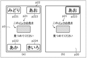
- the test image is rectangular.
- the first image p1 (see FIG. 4(a)) is presented to the test subject to obtain an answer
- the second image p2 (see FIG. 5(a)) is presented to the test subject.
- a test in which the third image p3 (see (a) in FIG. 6) is presented to the test subject and the fourth image p4 (see (a) in FIG. 7) is (see) to the test subject and obtain an answer.
- red is represented by solid line hatching
- blue is represented by broken line hatching
- green is represented by dot hatching
- yellow is represented by diamond-shaped hatching. This kind of color expression is the same in the drawings that appear later.
- FIG. 4 is a diagram showing an example of the first image p1.
- (a) of FIG. 4 shows the first image p1
- (b) of FIG. 4 shows the correct image p10 for the first image p1.
- the first image p1 is a test image for presenting the Stroop task to the subject to obtain an answer.
- the Stroop task is a task for confirming the influence of the Stroop effect on a subject, and in particular, a task for confirming the extent to which a subject is strongly influenced by interference from text.
- the first image p1 includes a question area p11 and an answer area p12.
- the problem area p11 is an area in which problems for the subject are displayed, and is located at the center of the first image p1 (that is, the examination image).
- the problem area p11 includes a character string indicating the color name (here, "yellow") and the color of the ink used in the character string (here, blue).
- a question statement in this case, ⁇ Please look at the color of the ink on this letter''
- the character string indicating the color name means an ink color different from the correct ink color.
- the answer area p12 is an area where a plurality of options (here, four options p121 to p124) selected by the subject to answer the question are displayed, and the answer area p12 is an area where the first image p1 (that is, the test image) is displayed. are located at multiple corners (here, four corners) of
- the plurality of options includes a correct answer option indicating a correct answer to the question for the subject, and one or more incorrect answer options indicating an incorrect answer to the question for the subject.
- the one or more incorrect options include a decoy option to which the subject can be guided by the Stroop effect. In other words, the decoy option is the option that most strongly interferes with the correct option among one or more incorrect options.
- the correct option is option p121, which is a character string indicating the correct ink color (here, "blue"), and is located in the upper left corner of the first image p1.
- one or more incorrect answer options are each a character string indicating the incorrect ink color (here, "red”, “green”, “yellow”).
- the three options p122 to p124 are located at each of the three corners of the first image p1 excluding the upper left corner. In the example shown in FIG.
- the decoy option is an option p124, which is a character string (here, "yellow") indicating the name of the color in the problem area p11, and is on the right side of the first image p1. Located in the bottom corner. In other words, the correct answer option and the decoy option are located diagonally across the problem area p11.
- the correct answer image p10 for the first image p1 is an image that presents the correct answer to the Stroop task to the subject, and as shown in FIG. 4(b), a problem area p11 similar to the first image p1,
- the correct answer option (here, option p121) is included.
- the correct answer options may be highlighted and displayed, for example, by being surrounded by a relatively thick line.
- FIG. 5 is a diagram showing an example of the second image p2.
- (a) of FIG. 5 shows the second image p2
- (b) of FIG. 5 shows the correct image p20 for the second image p2.
- the second image p2 is a test image for presenting the Stroop control task to the subject and obtaining an answer.
- the Stroop control task is a task for confirming whether or not the subject has the ability to answer the questions in the Stroop task before presenting the Stroop task to the subject.
- the Stroop control task is a task for confirming whether the subject can recognize the color of ink.
- the second image p2 includes a question area p21 and an answer area p22.
- the problem area p21 is an area in which problems for the subject are displayed, and is located at the center of the second image p2 (that is, the examination image).
- the problem area p21 includes a rectangular area filled with the correct ink color (in this case, blue), and a rectangular area filled with the ink color used for the rectangular area.
- a question statement here, "Please look at the color of this ink" asking about the color (here, blue) is displayed.
- the answer area p22 is an area where a plurality of options (here, four options p221 to p224) selected by the subject to answer the question are displayed, and the answer area p22 is an area where the second image p2 (that is, the test image) is displayed. are located at multiple corners (here, four corners) of The plurality of options includes a correct answer option indicating a correct answer to the question for the subject, and one or more incorrect answer options indicating an incorrect answer to the question for the subject. Note that in the Stroop control task, one or more incorrect answer choices do not include a decoy choice.
- the correct option is option p223, which is a character string indicating the correct ink color (here, "blue"), and is located in the upper right corner of the second image p2.
- one or more incorrect answer options are each a character string indicating the incorrect ink color (here, "green”, “red”, “yellow”).
- Three options p221, p222, and p224 are located at the three corners of the second image p2 excluding the upper right corner, respectively.
- the correct answer image p20 for the second image p2 is an image that presents the correct answer to the Stroop control task to the subject, and as shown in FIG. , the correct answer option (here, option p223).
- the correct options may be displayed in an emphasized manner, for example, by being surrounded by a relatively thick line.
- FIG. 6 is a diagram showing an example of the third image p3.
- (a) of FIG. 6 shows the third image p3, and (b) of FIG. 6 shows the correct image for the third image p3.
- the third image p3 is a test image for presenting the reverse Stroop task to the subject to obtain an answer.
- the reverse Stroop task is a task for confirming the influence of the Stroop effect on a subject, and in particular, a task for confirming the extent to which a subject is strongly affected by interference from color.
- the third image p3 includes a question area p31 and an answer area p32.
- the problem area p31 is an area in which problems for the subject are displayed, and is located at the center of the third image p3 (that is, the examination image).
- the problem area p31 includes a character string indicating the name of the color (here, "red”) and a question sentence asking about the meaning of the character string (here, red).
- the message "Please look at the color represented by this word” is displayed.
- the character string indicating the color name is expressed in an ink color (here, blue) that is different from the correct ink color.
- the answer area p32 is an area where a plurality of options (here, four options p321 to p324) selected by the subject to answer the question are displayed, and the third image p3 (that is, the test image) are located at multiple corners (here, four corners) of
- the plurality of options includes a correct answer option indicating a correct answer to the question for the subject, and one or more incorrect answer options indicating an incorrect answer to the question for the subject.
- the one or more incorrect options include a decoy option to which the subject can be guided by the Stroop effect.
- the correct answer option is option p322, which is a rectangular area filled with the correct ink color (red in this case), and is located in the lower left corner of the third image p3.
- one or more incorrect answer options are divided into three rectangular areas each filled with the incorrect ink color (in this case, blue, yellow, and green).
- Options p321, p323, and p324 are located at three corners of the third image p3, excluding the lower left corner.
- the decoy option is a rectangular area filled with the color (here, blue) used in the character string indicating the color name in the problem area p31.
- the option p321 is located at the upper left corner of the third image p3.
- the correct answer option and the decoy option are not located diagonally across the problem area p31, but even if they are located diagonally across the problem area p31. good.
- the correct answer image p30 for the third image p3 is an image that presents the correct answer to the reverse Stroop task to the subject, and as shown in FIG. , a correct answer option (here, option p322).
- the correct answer options may be displayed in an emphasized manner, for example, by being surrounded by a relatively thick line.
- FIG. 7 is a diagram showing an example of the fourth image p4. (a) of FIG. 7 shows the fourth image p4, and (b) of FIG. 7 shows the correct image p40 for the fourth image p4.
- the fourth image p4 is a test image for presenting the reverse Stroop control task to the subject and obtaining an answer.
- the reverse Stroop control task is a task to confirm whether or not the test subject has the ability to answer the questions in the reverse Stroop task before presenting the reverse Stroop task to the test subject. be.
- the reverse Stroop control task is a task for confirming whether the subject can recognize the meaning expressed by a character string.
- the fourth image p4 includes a question area p41 and an answer area p42.
- the problem area p41 is an area in which problems for the subject are displayed, and is located at the center of the fourth image p4 (that is, the examination image).
- the problem area p41 includes a character string indicating the name of the color (here, "red") and a question statement asking about the meaning of the character string (here, red).
- the message "Please look at the color represented by this word” is displayed.
- the ink color of the character string indicating the color name is an ink color (here, black) that is different from the ink colors that can be selected by the subject.
- the answer area p42 is an area where a plurality of options (here, four options p421 to p424) selected by the subject to answer the question are displayed, and the answer area p42 is an area where the fourth image p4 (that is, the examination image) is displayed. are located at multiple corners (here, four corners) of The plurality of options includes a correct answer option indicating a correct answer to the question for the subject, and one or more incorrect answer options indicating an incorrect answer to the question for the subject. In addition, in the reverse Stroop control task, one or more incorrect answer choices do not include a decoy choice.
- the correct answer option is option p423, which is a rectangular area filled with the correct ink color (red in this case), and is located in the upper right corner of the fourth image p4. To position.
- one or more incorrect answer options are divided into three rectangular areas each filled with the incorrect ink color (here, green, blue, and yellow).
- Options p421, p422, and p424 are located at three corners of the fourth image p4, excluding the upper right corner, respectively.
- the correct answer image p40 for the fourth image p4 is an image that presents the correct answer to the reverse Stroop control task to the subject, and as shown in FIG. and a correct answer option (here, option p423).
- the correct answer option may be displayed in an emphasized manner by, for example, being surrounded by a relatively thick line.
- FIG. 8 is a flowchart showing an example of the operation of the Stroop inspection system 1 in the embodiment.
- the Stroop test process shown in FIG. 8 is mainly realized by the PC 30 executing the Stroop test program 311. Note that a calibration process for viewpoint detection may be executed before executing the Stroop test process shown in FIG. 8 .
- the PC 30 executes a process of displaying a test image for the Stroop test on the display device 10 (S101).
- the PC 30 acquires the subject's gaze position information regarding the examination image displayed on the display device 10 (S102).
- the PC 30 shown in FIG. 1A detects the position of the examinee's viewpoint in the examination image by the detection unit 37, and creates a distribution map of the examinee with respect to the examination image by the creation unit 38. , obtain the subject's gaze position information.
- the PC 30 shown in FIG. 1B uses the acquisition unit 40 to acquire gaze position information of the subject from an external device.
- the PC 30 generates evaluation information of the subject based on the acquired gaze position information (in other words, the created distribution map) (S103).
- the PC 30 sets the question area and answer area in the inspection image as a region of interest (ROI), and generates evaluation information by calculating the gaze rate in the region of interest.
- the gaze rate is a parameter that represents the ratio of the number of viewpoints of the subject in the region of interest to the total number of viewpoints of the subject during the time the inspection image is displayed, expressed as a percentage.
- the PC 30 calculates the gaze rate of the problem area, the gaze rate of the correct answer option, and the gaze rate of the decoy option.
- the PC 30 repeatedly executes steps S101 to S103 described above until all inspection images are displayed on the display device 10 (S104: No). That is, when a plurality of inspection images exist, the PC 30 sequentially displays the inspection images on the display device 10 at predetermined time intervals, and executes steps S101 to S103 described above each time an inspection image is displayed on the display device 10. do. Then, when the PC 30 displays all the inspection images on the display device 10 (S104: Yes), the PC 30 outputs the evaluation information by displaying the generated evaluation information on the display unit 35 (S105). Note that step S105 may be executed every time evaluation information is generated in step S103.
- FIG. 9 is a diagram showing an example of a timeline of images displayed on the display device 10 in the Stroop test according to the embodiment.
- FIG. 10 is a diagram illustrating a display example of a test image and a correct image.
- FIG. 11 is a diagram showing a display example of a switching image.
- the PC 30 first displays start images p51 and p52 in order on the display device 10 to notify the subject of the start of the Stroop test.
- the start image p51 includes a character string (here, "The test is about to begin") for notifying the subject of the start of the Stroop test in its center.
- the start image p52 includes a character string (here, "Please find the correct answer and look carefully") for explaining how to answer in the Stroop test at its center.
- the display time of the start image p51 is, for example, about 2.5 seconds
- the display time of the start image p52 is, for example, about 2.5 seconds.
- the PC 30 displays the test image (fourth image p4) for the reverse Stroop control task on the display device 10.
- the PC 30 sequentially displays a plurality of problem sets (for example, four problem sets) on the display device 10, with the fourth image p4 and the correct image p40 as one problem set.
- the display time of one problem set is, for example, about 8 seconds or 10 seconds.
- the PC 30 displays a fade-in image p8 showing a fade-in effect, a test image (here, the second image p2), as shown in FIG. , a correct image (here, correct image p20), and a fade-out image p9 showing a fade-out effect are displayed in order on the display device 10.
- the display time of the fade-in image p8 is, for example, about 0.5 seconds
- the display time of the test image is, for example, about 5 seconds or 7 seconds
- the display time of the correct image is, for example, about 2 seconds
- the display time of the test image is, for example, about 2 seconds.
- the display time of the image p9 is, for example, about 0.5 seconds. Note that when displaying one problem set on the display device 10, the PC 30 does not need to display the fade-in image p8 and the fade-out image p9 on the display device 10.
- the PC 30 displays a switching image p6 on the display device 10 to notify the subject that the subject of the Stroop test will be switched.
- the switching image p6 includes in its center a character string (here, "the type of question will change") for notifying the subject that the Stroop test task will be switched.
- the PC 30 sequentially displays a fade-in image p61 showing a fade-in effect, a switching image p6, and a fade-out image p62 showing a fade-out effect, as shown in FIG. Displayed on the device 10.
- the display time of the fade-in image p61 is, for example, about 0.5 seconds
- the display time of the switching image p6 is, for example, about 2 seconds
- the display time of the fade-out image p62 is, for example, about 0.5 seconds. Note that when displaying the switching image p6 on the display device 10, the PC 30 does not need to display the fade-in image p61 and the fade-out image p62 on the display device 10.
- the PC 30 displays the test image (third image p3) for the reverse Stroop task on the display device 10.
- the PC 30 sequentially displays a plurality of problem sets (for example, four problem sets) on the display device 10, with the third image p3 and the correct image p30 as one problem set.
- the way the problem set is displayed here is the same as the way the problem set is displayed in the reverse Stroop control task.
- the PC 30 displays the switching image p6 on the display device 10.
- the method of displaying the switching image p6 here is the same as the method of displaying the switching image p6 described above.
- the PC 30 displays the test image (second image p2) for the Stroop control task on the display device 10.
- the PC 30 sequentially displays a plurality of problem sets (for example, four problem sets) on the display device 10, with the second image p2 and the correct image p20 as one problem set.
- the way the problem set is displayed here is the same as the way the problem set is displayed in the reverse Stroop control task.
- the PC 30 displays the switching image p6 on the display device 10.
- the method of displaying the switching image p6 here is the same as the method of displaying the switching image p6 described above.
- the PC 30 displays the test image (first image p1) for the Stroop task on the display device 10.
- the PC 30 sequentially displays a plurality of problem sets (for example, four problem sets) on the display device 10, with the first image p1 and the correct image p10 as one problem set.
- the way the problem set is displayed here is the same as the way the problem set is displayed in the reverse Stroop control task.
- the PC 30 displays the switching image p6 on the display device 10.
- the method of displaying the switching image p6 here is the same as the method of displaying the switching image p6 described above.
- the PC 30 displays the end image p7 on the display device 10 to notify the subject of the end of the Stroop test.
- the end image p7 includes a character string (here, "This is the end of the test. Thank you for your hard work") for notifying the subject of the end of the Stroop test in its center.
- the display time of the end image p7 is, for example, about 2 seconds.
- the PC 30 displays the test image for the reverse Stroop control task (fourth image p4), the test image for the reverse Stroop task (third image p3), and the test image for the Stroop control task (the fourth image p4).
- the test images are displayed on the display device 10 in the order of the second image p2) and the test image for the Stroop task (the first image p1), the order is not limited to this.
- the PC 30 displays a test image for the Stroop control task (second image p2), a test image for the Stroop task (first image p1), a test image for the reverse Stroop control task (fourth image p4), and a test image for the reverse Stroop control task (the fourth image p4).
- Each test image may be displayed on the display device 10 in the order of the test image (third image p3) regarding the task.
- the PC 30 may omit displaying the test image for the Stroop control task (second image p2) and the test image for the reverse Stroop control task (fourth image p4).
- the PC 30 may omit displaying the correct answer image when displaying one problem set on the display device 10.
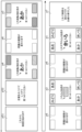
- FIG. 12 is a diagram illustrating an example of evaluation information of a test subject (that is, a healthy person) who has no impairment in cognitive function including attention.
- FIG. 13 is a diagram illustrating an example of evaluation information of a test subject with a cognitive function disorder including attention (that is, a person with a cognitive disorder).
- Both (a) of FIG. 12 and (a) of FIG. 13 show that the test results (evaluation information) for the Stroop control task are displayed on the display unit 35.
- the second image p2 is displayed on the display unit 35.
- a distribution map of the subject is displayed in a superimposed manner on the second image p2.
- the subject's gaze rate of the correct answer option is displayed superimposed on the second image p2.
- FIG. 12(b) and FIG. 13(b) both show that the test results (evaluation information) for the Stroop task are displayed on the display unit 35.
- the first image p1 is displayed on the display unit 35.
- a distribution map of the subject is displayed in a superimposed manner on the first image p1.
- the subject's gaze rate for the correct answer option and the subject's gaze rate for the decoy option are superimposed on the first image p1. may be displayed.
- heat map information is expressed by dot shading. There is. In other words, the higher the density of the dots, the more concentrated the viewpoint is.
- both the healthy subjects and the cognitively impaired subjects focused on the correct option (here, option p221), and in the Stroop control task. Select the correct answer. Furthermore, the rate of attention to the correct answer options was 91.3% for the healthy subjects and 90.9% for the cognitively impaired subjects, and both of them reached the correct answer on the Stroop control task without any particular hesitation.
- the fact that the test subjects (in this case, healthy subjects and cognitively impaired subjects) reach the correct answer to the task without hesitation is quantitatively expressed as a high fixation rate. important for the evaluation of Therefore, by referring to the evaluation information shown in FIGS. 12(a) and 13(a), it can be seen that both healthy people and people with cognitive impairment are able to correctly recognize the color of ink. I understand.
- the healthy person's viewpoint is concentrated on the correct answer option (here, option p123) and selects the correct answer for the Stroop task. Moreover, the healthy person does not pay attention to the decoy option (here, option p122) at all. Focusing on the attention rate, healthy subjects' attention rate for the correct answer option was 95.2%, and the attention rate for the decoy option was 0%, allowing them to arrive at the correct answer to the Stroop task without hesitation. Therefore, by referring to the evaluation information shown in FIG. 12(b), it can be seen that a healthy person is hardly affected by the Stroop effect, that is, is hardly affected by interference from characters. Here, the fact that the test subject (in this case, a healthy person) receives almost no interference from the text is quantitatively expressed as a low fixation rate for the decoy option. It is important for the evaluation of people.
- the cognitively impaired person hardly pays attention to the correct answer options and does not select the correct answer for the Stroop task. Additionally, the perspective of people with cognitive impairments focuses on decoy options. Focusing on the rate of attention, the rate of attention for the correct option for people with cognitive impairment was 0.8%, and the rate of attention for the decoy option was 91.8%. Therefore, by referring to the evaluation information shown in FIG. 13(b), it can be seen that the cognitively impaired person is strongly affected by the Stroop effect, that is, interference from text.
- the fact that the test subject in this case, a person with cognitive impairment
- receives strong interference from text is quantitatively expressed as a high fixation rate for the decoy option, which is shown in the Stroop test. Important for patient evaluation.
- the evaluation information it is possible to quantitatively evaluate the examinee's attentiveness and judgment.
- the degree of correct answer in one question and the degree of influence of the Stroop effect are quantitatively expressed as continuous variables.
- the evaluation obtained for one question is only a discrete binary value of 1 point for a correct answer and 0 points for an incorrect answer.
- the degree of correct answers and the degree of influence of the Stroop effect can be expressed quantitatively as continuous variables, so the number of questions asked to the test subject can be reduced compared to the conventional Stroop test. It is possible to shorten the time required for the Stroop test.
- FIG. 14 a comparison result between the Stroop test system 1 according to the embodiment, that is, the Stroop test method according to the embodiment, and the conventional Stroop test will be described using FIG. 14.
- the vertical axis shows the examinee's fixation rate for the correct answer option in the Stroop test in the embodiment, and the horizontal axis represents the examinee's score in the conventional Stroop test.
- the vertical axis shows the subject's fixation rate for the decoy options in the Stroop test in the embodiment
- the horizontal axis shows the subject's score in the conventional Stroop test. There is.
- FIG. 14 shows the examinee's fixation rate for the correct answer option in the Stroop test in the embodiment, and the horizontal axis represents the examinee's score in the conventional Stroop test.
- the vertical axis shows the subject's fixation rate for the decoy options in the Stroop test in the embodiment
- the horizontal axis shows the subject's score in the conventional Stroop test.
- the vertical axis represents the subject's gaze rate on the problem area in the Stroop test according to the embodiment, and the horizontal axis represents the subject's score in the conventional Stroop test.
- the broken line represents a regression line
- "R” represents a correlation coefficient
- "P” represents a P value.
- the display time of the test image is 7 seconds
- the display time of the correct image is 1 second
- the display time of the switching image is 1 second.
- the results of the Stroop test in the embodiment show the results for a total of 4 Stroop tasks
- the results of the conventional Stroop test show the results for a total of 60 Stroop tasks in the new Stroop test I. Showing.
- the test subject's score on the conventional Stroop test represents the number of correct answers out of a total of 60 questions.
- the examinee's fixation rate for the correct answer option in the Stroop test in the embodiment increases as the examinee's score in the conventional Stroop test increases, It has a positive correlation with the test subject's score on the conventional Stroop test.
- the rate of fixation of the subject's decoy options in the Stroop test in the embodiment decreases as the subject's score in the conventional Stroop test increases. and has a negative correlation.
- the rate of fixation of the subject's problem area in the Stroop test in the embodiment decreases as the subject's score in the conventional Stroop test increases. and has a negative correlation.
- the Stroop test in the embodiment has the same effectiveness as the conventional Stroop test, although the number of questions presented to the examinee is small. Furthermore, the Stroop test in the embodiment can also evaluate a parameter that cannot be evaluated using the conventional Stroop test, such as the gaze rate of the problem area.
- the information about what kind of thinking process led to the correct or incorrect answer is essential information that reflects the degree of information interference in the Stroop effect, but conventional methods based on existing interview methods In the Stroop test, such information can only be inferred indirectly from the time required or the percentage of correct or incorrect answers. For this reason, in the conventional Stroop test, in order to obtain an accurate evaluation, it is necessary to pose many questions to the test subject, which increases the burden on the test subject and the tester.
- the line of sight position indicating the position of the subject's line of sight in the test image for the Stroop test is Information is acquired, and evaluation information indicating the evaluation of the subject is generated based on the acquired gaze position information. Therefore, in the Stroop test according to the embodiment, the thinking process of the examinee while displaying the test image (how much he/she was confused between the correct and incorrect options) is reflected as the degree of attention towards each option. For the first time, it became possible to express the Stroop effect as an objective continuous value.
- the Stroop test in the embodiment information such as the attention rate of the correct answer option or the attention rate of the decoy option can be obtained simultaneously from one task, so the influence of the Stroop effect can be quantitatively evaluated with a relatively small number of questions. It is possible to do so. Therefore, in the Stroop test according to the embodiment, the burden on the subject and the examiner can be reduced compared to the conventional Stroop test.
- the test is performed at predetermined intervals. The image is forcibly shifted to the next inspection image. Therefore, in the Stroop test according to the embodiment, it is also possible to quantitatively evaluate whether the test subject was able to select the correct answer option within a predetermined time, that is, the answer time allotted for each question.
- the Stroop test system 1 in the embodiment that is, the Stroop test method
- the Stroop test method has the advantage that the test can be performed easily and quantitative evaluation can be easily obtained. If the Stroop test according to the embodiments makes it possible to more easily and quantitatively evaluate the Stroop effect, it will be widely used in clinical or health care as a simple testing method for cognitive dysfunction such as dementia. It is expected that it will be utilized in the field.
- the test image is rectangular, and multiple options in the answer area are located at multiple corners (that is, four corners). Therefore, in the embodiment, the distance from the problem area to each option is equal, in other words, the position of each option with respect to the problem area is equivalent, so there is an advantage that it becomes easier to evaluate the test subject more accurately.
- the distance from the problem area to the option affects the time it takes for the subject's line of sight to reach the option from the problem area, and ultimately the gaze rate within a limited time after reaching the option.
- the gaze rate of the correct option indirectly takes into account the time it takes for the examinee's line of sight to reach the correct option, and the time depends on the distance from the problem area to the correct option.
- each option by arranging each option as described above, the distance between the problem area and each option can be made as long as possible even when the accuracy of detecting the subject's line of sight by eye tracking is relatively low. This also has the advantage of making it difficult to incorrectly evaluate answers based on the subject's line of sight.
- the correct answer option and the decoy option are located diagonally across the problem area. Therefore, the embodiment has the advantage that, in the process of directing the examinee's gaze to either the correct option or the decoy option, it is possible to reduce the possibility that the subject unconsciously (accidentally) sees the other option. There is. For example, when a test subject looks at a decoy option, the test subject is intentionally looking at the correct answer, believing that the answer is correct. This has the advantage of making it easier for the examiner to assess whether he or she is being guided by the decoy option.
- the evaluation information includes information indicating the degree to which the subject gazed at the correct answer options (here, the gaze rate of the correct answer options).
- the embodiment has an advantage in that it is possible to grasp the improvement in the rate of fixation of correct answer options by the test subject when the same type of question is repeatedly presented to the test subject for one task.
- by focusing on the rate of fixation of the correct answer option by the test subject in the question immediately after the task presented to the test subject is switched it is easy to accurately evaluate the influence of the Stroop effect on the test subject.
- the influence of the Stroop effect on the examinee that is, the interference from text or color, is strongest in the question immediately after the task is switched.
- the evaluation information includes information indicating the degree to which the subject gazed at the decoy options (here, the attention rate of the decoy options). Therefore, the embodiment has the advantage that it is possible to quantify the degree to which the subject was guided by the decoy option, in other words, the degree to which the subject was influenced by the Stroop effect. In this way, in the embodiment, since the above two pieces of information are included in the evaluation information, it is easy to evaluate the attentiveness to understand the question correctly and the attentiveness to focus on the correct answer after understanding the question. It has the advantage of being.
- the Stroop test image generation method is a method for generating test images for Stroop tests.
- the test image generated by the Stroop test image generation method is stored in the storage unit 32 as test image data 300.
- FIG. 15 is a flowchart illustrating an example of a Stroop test image generation method in the embodiment.
- the Stroop test image generation process shown in FIG. 15 is realized by the PC 30 executing the Stroop test image generation program 312.
- the Stroop test image generation method includes multiple sets of test images for the Stroop task, multiple sets of test images for the Stroop control task, multiple sets of test images for the reverse Stroop task, and tests for the reverse Stroop control task. Generate multiple sets of images.
- Each of the plurality of sets includes a plurality of questions, in other words, a plurality of test images.
- the Stroop test image generation method shown in FIG. 15 shows a basic example of generating a test image set for one of these tasks.
- the PC 30 determines the correct answer option for each question (S201).
- the PC 30 determines decoy options for each question (S202).
- the PC 30 determines a decoy option for each question to be different from the correct answer option and the correct answer option for the next question.
- the PC 30 determines the position of the correct answer option in the test image for each question (S203).
- the PC 30 determines the position of the correct answer option for each question so that it is on the opposite side in the vertical direction from the position of the correct answer option for the previous question.
- the PC 30 determines the position of the decoy option in the test image for each question (S204).
- step S204 the PC 30 determines the position of the decoy option for each question so that it is on the opposite side of the correct answer option in the vertical direction. Then, the PC 30 determines the positions of the remaining incorrect answer options in the test image for each question (S205). As a result, a test image set for one subject is generated.
- FIG. 16 is a diagram illustrating an example of test image data for a Stroop task generated by the Stroop test image generation method according to the embodiment.
- “ink color (correct answer)” represents the correct answer option
- “text (interference)” represents the decoy option.
- FIG. 17 is a diagram illustrating an example of test image data for a Stroop control task generated by the Stroop test image generation method according to the embodiment.
- FIG. 18 is a diagram illustrating an example of test image data for a reverse Stroop task generated by the Stroop test image generation method according to the embodiment.
- FIG. 16 is a diagram illustrating an example of test image data for a Stroop task generated by the Stroop test image generation method according to the embodiment.
- FIG. 19 is a diagram illustrating an example of test image data for a reverse Stroop control task generated by the Stroop test image generation method according to the embodiment.
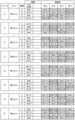
- Each inspection image data includes two series (here, series A and series B). Additionally, each series includes four sets. Each set includes four questions (that is, test images). Therefore, here, the Stroop test image generation method according to the embodiment generates a total of 32 test images for one task, and a total of 128 test images for four tasks. Note that the number of series, the number of sets included in one series, and the number of questions (that is, test images) included in one set may be arbitrary.
- the PC 30 generates a first set of test images for the Stroop task.
- the PC 30 determines the initial parameter, that is, the correct answer option for the first question (here, the correct ink color).
- the PC 30 determines the initial parameters by accepting input of initial parameters by the operator through the input unit 33, for example. In addition, the PC 30 may randomly determine the initial parameters by itself.
- the PC 30 alternately determines the correct answer option for the second question, the correct answer option for the third question, and the fourth correct answer option such that the number of characters in the correct answer option is either 2 or 3 characters.
- the PC 30 determines the decoy options for each question.
- the PC 30 sets the ink color of the decoy option of each question to be different from the ink color of the correct answer option, different from the ink color of the correct answer option of the next question, and basically the number of characters of the correct answer option. The number of characters is determined to be different from . Note that if there is no ink color that satisfies the third condition, the PC 30 may determine an ink color with the same number of characters as the correct option as the ink color of the decoy option.
- the PC 30 determines the position of each option in the inspection image for each question.
- the PC 30 randomly determines the position of the correct answer option for the first question.
- the PC 30 sets the position of the correct answer option for the second and subsequent questions on either the left or right side, which is opposite to the position of the correct answer option of the previous question in the vertical direction, and the position of the correct answer option of other questions in the same set. Decide to avoid duplication.
- the PC 30 places an incorrect answer option with an ink color that has a different number of characters from the number of characters in the correct answer option next to the correct answer option in the left and right direction, so as not to overlap with the incorrect answer option in the previous question if possible. Deploy.
- the PC 30 determines the position of the decoy option for each problem on either the left or right side, which is opposite to the position of the correct answer option in the vertical direction, and so that it does not overlap with the position of the decoy option of other questions in the same set. . In this way, the PC 30 generates the first set of test images for the Stroop task.
- the PC 30 generates a second set of test images for the Stroop task.
- the PC 30 determines the correct answer option for each question.
- the PC 30 determines the correct answer option for the first question so that it does not appear as a correct answer option in at least the previous question and the question before the previous one, and does not overlap with the correct answer option for the first question in the previous set.
- the PC 30 determines the correct answer option for the second question so that it does not appear as a correct answer option in at least the previous question and the question before the previous question, and does not overlap with the correct answer option for the first question.
- the PC 30 determines the correct answer option for the third question and the correct answer option for the fourth question so that they do not overlap with the order of the correct answer option for the third question and the correct answer option for the fourth question in the previous set.
- the PC 30 determines the decoy options for each question.
- the PC 30 sets the ink color of the decoy option of each question to be different from the ink color of the correct answer option, different from the ink color of the correct answer option of the next question, and basically the number of characters of the correct answer option. The number of characters is determined to be different from . Note that if there is no ink color that satisfies the third condition, the PC 30 may determine an ink color with the same number of characters as the correct option as the ink color of the decoy option.
- the PC 30 determines the position of each option in the inspection image for each question.
- the PC 30 determines the position of the correct answer option for the first question to be adjacent in the left and right direction to the position of the correct answer option for the second question of the previous set (first set).
- the PC 30 determines the position of the correct answer option for the second question to be adjacent in the left and right direction to the position of the correct answer option for the second question of the previous set (first set).
- the PC 30 determines the position of the correct answer option for the third question to be adjacent in the left and right direction to the position of the correct answer option for the third question of the previous set (first set).
- the PC 30 determines the position of the correct answer option for the fourth question to be adjacent in the left-right direction to the position of the correct answer option for the fourth question of the previous set (first set). That is, the PC 30 determines the position of the correct answer option for each question to be the position opposite to the position of the correct answer option of the previous question in the vertical direction.
- the "previous question” here corresponds to the fourth question of the previous set in the case of the first question.
- the PC 30 adds an incorrect answer option with an ink color that has a different number of characters from the number of characters in the correct answer option next to the correct answer option in the left and right direction, if possible, and also adds an incorrect answer option that does not overlap with the incorrect answer option in the previous question. Place it like this.
- the PC 30 sets the position of the decoy option for each problem on either the left or right side opposite to the position of the correct answer option in the vertical direction, and so that it does not overlap with the position of the decoy option for the same problem in the previous set. decided on. For example, the PC 30 determines the position of the decoy option for the first question so as not to overlap with the position of the decoy option for the first question of the first set. In this way, the PC 30 generates the second set of test images for the Stroop task.
- the PC 30 generates a third set of test images for the Stroop task.
- the PC 30 determines the correct answer option for each question.
- the PC 30 determines the correct answer option for the first question as the correct answer option for the first question of the first set.
- the PC 30 determines the correct answer option for the second question so that it does not appear as a correct answer option in at least the previous question and the question before the previous one, and does not overlap with the correct answer option for the second question in the first set.
- the PC 30 determines the correct answer option for the third question to be a color with the same number of characters as the correct answer option for the second question.
- the PC 30 determines the ink color of the correct answer option for the fourth question to be an ink color that has not yet been used in the same set.
- the PC 30 determines the decoy options for each question.
- the PC 30 determines the ink color of the decoy option for each question to be different from the ink color of the correct answer option and different from the ink color of the correct answer option of the next question. Further, the PC 30 determines the ink color for the decoy option of the first question to have the same number of characters as the correct answer option. Note that if there is no ink color that satisfies the third condition, the PC 30 may determine an ink color with the same number of characters as the correct option as the ink color of the decoy option.
- the PC 30 determines the position of each option in the inspection image for each question.
- the PC 30 sets the position of the correct answer option of the first question to be on the opposite side in the vertical direction from the position of the correct answer option of the first question of the first set, and to Determine the position so that it does not overlap with the position of question 4.
- the PC 30 determines the position of the correct answer option for the second question to be on the opposite side in the vertical direction to the position of the correct answer option for the first question, but at the same position on the left and right.
- the PC 30 determines the position of the correct answer option for the third question to be adjacent in the left-right direction to the position of the correct answer option for the first question.
- the position is the position opposite to the position of the correct answer option for the second question in the vertical direction.
- the PC 30 determines the position of the correct answer option for the fourth question at a position that has not yet been used in the same set.
- the PC 30 adds an incorrect answer option with an ink color that has a different number of characters from the number of characters in the correct answer option next to the correct answer option in the left and right direction, if possible, and also adds an incorrect answer option that does not overlap with the incorrect answer option in the previous question. Place it like this.
- the PC 30 sets the position of the decoy option for the first question on either the left or right side, which is opposite to the position of the correct answer option in the vertical direction, and so that it does not overlap with the position of the decoy option for the fourth question of the second set. decide.
- the PC 30 determines the position of the decoy option for the second question on the diagonal of the test image, on the opposite side of the correct answer option across the question area.
- the PC 30 determines the position of the decoy option for the third question to be adjacent in the left-right direction to the position of the decoy option for the first question.
- the PC 30 determines the position of the decoy option for the fourth question at a position that has not yet been used in the same set. In this way, the PC 30 generates the third set of test images for the Stroop task.
- the PC 30 generates a fourth set of test images for the Stroop task.
- the PC 30 determines the correct answer option for each question.
- the PC 30 determines the correct answer option for the first question so that it does not appear as a correct answer option in at least the previous question and the question before the previous one, and does not overlap with the correct answer option for the first question in the previous set.
- the PC 30 determines the correct answer option for the second question so that it does not appear as a correct answer option in at least the previous question and the question before the previous question, and does not overlap with the correct answer option for the first question.
- the PC 30 determines the correct answer option for the third question and the correct answer option for the fourth question so that they do not overlap with the order of the correct answer option for the third question and the correct answer option for the fourth question in the previous set.
- the PC 30 determines the decoy options for each question.
- the PC 30 determines the ink color of the decoy option for each question to be different from the ink color of the correct answer option and different from the ink color of the correct answer option of the next question. Further, the PC 30 determines the ink color for the decoy option of the first question to have the same number of characters as the correct answer option. Note that if there is no ink color that satisfies the third condition, the PC 30 may determine an ink color with the same number of characters as the correct option as the ink color of the decoy option.
- the PC 30 determines the position of each option in the inspection image for each question.
- the PC 30 determines the position of the correct answer option for the first question to be adjacent in the left-right direction to the position of the correct answer option for the first question of the previous set (third set).
- the PC 30 determines the position of the correct answer option for the second question to be adjacent in the left-right direction to the position of the correct answer option for the second question of the previous set (third set).
- the PC 30 determines the position adjacent to the correct answer option for the second question in the left and right direction.
- the PC 30 determines the position of the correct answer option for the fourth question at a position that has not yet been used in the same set.
- the PC 30 determines the position of the correct answer option for each question to be the position opposite to the position of the correct answer option of the previous question in the vertical direction.
- the PC 30 adds an incorrect answer option with an ink color that has a different number of characters from the number of characters in the correct answer option next to the correct answer option in the left and right direction, if possible, and also adds an incorrect answer option that does not overlap with the incorrect answer option in the previous question. Place it like this.
- the PC 30 sets the position of the decoy option for the first question on either the left or right side, which is opposite to the position of the correct answer option in the vertical direction, and the position of the decoy option for the first question in the previous set (third set). Decided not to overlap.
- the PC 30 determines the position of the decoy option of the second question so as not to overlap with the position of the decoy option of the second question of the previous set (third set).
- the PC 30 determines the position of the decoy option for the third question on either the left or right side, which is opposite to the position of the correct answer option in the vertical direction, and so that it does not overlap with the position of the decoy option in the first question. .
- the PC 30 determines the position of the decoy option for the fourth question at a position that has not yet been used in the same set. In this way, the PC 30 generates the fourth set of test images for the Stroop task.
- the PC 30 Based on the generated test image set for the Stroop task, the PC 30 replaces the character string indicating the ink color of each option with a rectangular area filled with the ink color. In this way, the PC 30 generates the first to fourth sets of test images for the Stroop control task.
- the PC 30 Based on the generated test image set for the Stroop task, the PC 30 rewrites the "ink color (correct answer)" column of the task to "letter (correct answer)” and converts the ink color name to black hiragana, Rewrite the "Character (interference)” column in the task to "Ink color (interference)” and convert the names of ink colors to the kanji that represent each color. Then, the PC 30 gives a background color to each option according to the name of the ink color. In this way, the PC 30 generates the first to fourth sets of test images for the reverse Stroop task. Note that in the Stroop test, hiragana among the options are not displayed on the display device 10.
- the PC 30 deletes the "ink color (interference)" of the task based on the generated test image set for the reverse Stroop task. In this way, the PC 30 generates the first to fourth sets of test images for the reverse Stroop control task.
- the PC 30 uses a series different from the series used in other tasks, for example, to avoid duplication of problem patterns with other tasks. , use a set different from the set used in other assignments, or use each problem in reverse order.
- the advantages of the Stroop test image generation method in the embodiment will be explained.
- the questions presented to the test subject are fixed, and if the test subject repeats the Stroop test, the test subject will memorize the questions and answers, reducing the effectiveness of the Stroop test. The problem is that it may be lost.
- the test image set used in the Stroop test can be randomly generated while following a predetermined rule. Therefore, if the Stroop test image generation method according to the embodiment is used, even if the test subject repeatedly performs the Stroop test, the test subject will not memorize the questions and answers, so the effectiveness of the Stroop test can be improved. It has the advantage of not losing its sexiness.
- the correct option and the decoy option do not have to be located diagonally.
- the correct answer option and the decoy option may be located on any straight line forming the cross.
- the multiple options in the answer area do not need to be located at each of the corners, but only need to be located around the question area.
- the multiple options may be located at equal intervals on the circumference surrounding the problem area.
- the problem area does not need to be located at the center of the inspection image.
- the problem area may be located in the upper half of the test image, and the answer area may be located in the lower half.
- the inspection image is not limited to a rectangular shape, and may be, for example, a polygonal shape other than a rectangular shape, a circular shape, or the like.
- the predetermined time which is the interval at which the inspection images are displayed on the display device 10, is fixed, but the time is not limited to this.
- the predetermined time may be determined based on the difficulty of the Stroop test or the age of the subject. That is, the predetermined time may be variable depending on the subject. For example, when the subject is a young person, the predetermined time may be set relatively short, and when the subject is an elderly person, the predetermined time may be set relatively long. Further, for example, if the difficulty of the Stroop test is high, the predetermined time may be set relatively short, and if the difficulty is low, the predetermined time may be set relatively long.
- the difficulty level of the Stroop test that the test subject takes is determined by, for example, the rate of attention to the correct answer option and the rate of attention to the problem area in each test when multiple Stroop tests are taken at different predetermined times. It is possible to decide based on For example, if the rate of attention to the correct answer option and the rate of attention to the problem area in each test are high, the difficulty level of the next Stroop test may be increased. Further, for example, if the rate of attention to the correct answer option and the rate of attention to the problem area in each test are low, the difficulty level of the next Stroop test may be lowered.
- the difficulty level of the Stroop test can be changed without changing the predetermined time.
- the evaluation unit 39 when generating evaluation information in the evaluation unit 39, by making the time to be evaluated in the distribution map shorter than a predetermined time, a state similar to the case where the predetermined time is shortened in a pseudo manner, that is, It is possible to realize a state in which the difficulty level of the Stroop test is increased. In this case, even if the test subject does not undergo a more difficult Stroop test such as by shortening the predetermined time, the test subject will be able to perform the It has the advantage of being able to evaluate
- the mode of changing the predetermined time according to the difficulty of the test or the age of the subject is not limited to the Stroop test, but can also be applied to other tests using eye tracking.
- the test method is a test method that shows the evaluation of the cognitive function of the test subject based on gaze position information that indicates the position of the test subject's line of sight in the test image
- the test method is a test method that shows the evaluation of the cognitive function of the test subject based on the gaze position information that indicates the position of the test subject's line of sight in the test image. It may also be a method of presenting the information to a person.
- the predetermined time may be determined based on the difficulty level of the test or the age of the subject.
- a plurality of test images may be presented to the subject in order, or a single test image may be presented to the subject.
- the Stroop test in the above embodiment can also be applied to the "Position Stroop Test", for example.
- the kanji characters "upper”, “middle”, and “lower” are randomly displayed in each of the upper, middle, and lower rows, and in the answer area, "upper", “lower”, It is sufficient that the kanji characters representing the correct and incorrect options such as "middle” and “lower” are displayed.
- the evaluation unit 39 then evaluates whether or not the subject can focus on the options indicating the positions of the kanji characters without being confused by the meanings of the kanji characters.
- test image is presented to the subject by being displayed on the display device 10, but the present invention is not limited to this.
- the test image may be presented to the subject by being displayed on paper.
- eye tracking makes it possible to obtain the locus of the examinee's line of sight in the examination image represented on the paper.
- the Stroop test image generation method may be at least the following method. That is, the Stroop test image generation method generates at least a plurality of test images so as to satisfy a predetermined condition.
- Each of the plurality of test images includes a problem area in which a question for the test subject is displayed, and a plurality of correct answer options and one or more incorrect answer options that the test subject selects to answer the question by looking at the question. and an answer area where options are displayed.
- the one or more incorrect choices include decoy choices to which the subject may be guided by the Stroop effect.
- the predetermined conditions are (1) that the problem area is located in the center of the test image, (2) that the answer region is located around the problem region, and (3) that the decoy options in the test image are located in the center of the test image. This includes a correct answer option and a difference from the correct answer option in the next test image presented to the subject.
- the Stroop test method of the first aspect evaluates the subject based on the line-of-sight position information indicating the position of the subject's line of sight in the test image (S102 to S105).
- the test image displays a problem area in which a question for the test subject is displayed, and a plurality of options including a correct answer option and one or more incorrect answer options for the test subject to select to answer the question by looking at the question. and a response area.
- the one or more incorrect choices include decoy choices to which the subject may be guided by the Stroop effect.
- a character string indicating the name of a color different from the correct color is asked, and the color used in the character string is asked.
- the correct answer option (option p121) is a character string indicating the color of the correct answer.
- the decoy option (option p124) is a character string indicating the name of the color in the problem area p11.
- a character string indicating the name of a color expressed in a color different from the correct color and a question about the meaning of the character string are provided in the problem area p31.
- the correct answer option (option p322) is an area filled with the color of the correct answer.
- the decoy option (option p321) is an area filled with the color used in the character string indicating the color name in the problem area p31.
- the problem area is located at the center of the test image, and the answer area is located around the problem area.
- the examinee's line of sight tends to scatter, and the examinee's line of sight to each option overlaps.
- the advantage is that it is difficult to do.
- the inspection image has a rectangular shape in the fourth aspect.
- the multiple options in the answer area are located at multiple corners of the test image.
- the correct answer option and the decoy option are located diagonally across the problem area.
- any one of the first to sixth aspects there is a plurality of inspection images.
- a plurality of inspection images are sequentially displayed at predetermined time intervals.
- the predetermined time is determined based on the difficulty level of the Stroop test or the age of the subject.
- the evaluation includes information indicating the degree to which the test subject gazed at the correct answer option, and information indicating the degree to which the test subject gazed at the decoy option. and information indicating the degree of
- the evaluation further includes information indicating the degree to which the subject focused on the problem area.
- test image is presented to the subject by being displayed on the display device 10.
- test image is easier to present to the test subject compared to the case where the test image represented on paper is presented to the test subject.
- the Stroop test program of the twelfth aspect acquires gaze position information indicating the position of the examinee's gaze in the examination image, and generates evaluation information indicating the evaluation of the examinee based on the acquired gaze position information.
- the computer generates the evaluation information and outputs the generated evaluation information.
- the test image displays a problem area in which a question for the test subject is displayed, and a plurality of options including a correct answer option and one or more incorrect answer options for the test subject to select to answer the question by looking at the question. and a response area.
- the one or more incorrect choices include decoy choices to which the subject may be guided by the Stroop effect.
- the Stroop inspection system 1 of the thirteenth aspect includes an acquisition section (detection section 37 and creation section 38, or acquisition section 40), an evaluation section 39, and an output section (display section 35).
- the acquisition unit acquires gaze position information indicating the position of the subject's gaze in the examination image.
- the evaluation unit 39 generates evaluation information indicating the evaluation of the subject based on the gaze position information acquired by the acquisition unit.
- the output unit outputs the evaluation information generated by the evaluation unit 39.
- the test image displays a problem area in which a question for the test subject is displayed, and a plurality of options including a correct answer option and one or more incorrect answer options for the test subject to select to answer the question by looking at the question. and a response area.
- the one or more incorrect choices include decoy choices to which the subject may be guided by the Stroop effect.
- the Stroop test image generation method of the fourteenth aspect generates a plurality of test images so as to satisfy a predetermined condition (S201 to S205).
- Each of the plurality of test images includes a problem area in which a question for the test subject is displayed, and a plurality of correct answer options and one or more incorrect answer options that the test subject selects to answer the question by looking at the question. and an answer area where options are displayed.
- the one or more incorrect choices include decoy choices to which the subject may be guided by the Stroop effect.
- the predetermined conditions are (1) that the problem area is located in the center of the test image, (2) that the answer region is located around the problem region, and (3) that the decoy options in the test image are located in the center of the test image. This includes a correct answer option and a difference from the correct answer option in the next test image presented to the subject.
- the predetermined condition is (4) positioning the correct answer option in each of the plurality of test images immediately before the test image with the problem area in between.
- the method further includes: placing the correct answer option on the opposite side of the test image presented to the person.
- the predetermined condition is (5) the position of the decoy option in each of the plurality of test images is set so that the correct answer is placed across the problem area. further comprising being opposite to the position of the option.
- the predetermined condition is (6) the test image is rectangular, and the plurality of options in the answer area is , respectively located at a plurality of corners of the inspection image.
- the examinee's line of sight tends to scatter, and the examinee's line of sight to each option overlaps.
- the advantage is that it is difficult to do.
- the predetermined condition further includes (7) that the correct answer option and the decoy option are located diagonally across the problem area. include.
- the Stroop test image generation program of the nineteenth aspect causes the computer to generate a plurality of test images so as to satisfy a predetermined condition.
- Each of the plurality of test images includes a problem area in which a question for the test subject is displayed, and a plurality of correct answer options and one or more incorrect answer options that the test subject selects to answer the question by looking at the question. and an answer area where options are displayed.
- the one or more incorrect choices include decoy choices to which the subject may be guided by the Stroop effect.
- the predetermined conditions are (1) that the problem area is located in the center of the test image, (2) that the answer region is located around the problem region, and (3) that the decoy options in the test image are located in the center of the test image. This includes a correct answer option and a difference from the correct answer option in the next test image presented to the subject.
- the testing method of the 20th aspect evaluates the cognitive function of the subject based on gaze position information indicating the position of the subject's line of sight in the inspection image.
- the test images are sequentially presented to the subject for a predetermined period of time.
- the predetermined time is determined based on the difficulty of the test or the age of the subject.
- the present invention can be used in a system, method, and program for performing a Stroop test.
Abstract
ストループ検査方法は、検査画像における被検者の視線の位置を示す視線位置情報に基づいて、被検者の評価を示す(S102~S105)。検査画像は、被検者に対する問題が表示される問題領域と、問題に対して被検者が視線により回答するために選択する正解選択肢及び1以上の不正解選択肢を含む複数の選択肢が表示される回答領域と、を有する。1以上の不正解選択肢には、ストループ効果により被検者が誘導され得るおとり選択肢が含まれる。
Description
本発明は、ストループ検査を実行するためのストループ検査方法、ストループ検査プログラム、ストループ検査システム、ストループ検査画像生成方法、ストループ検査画像生成プログラム、及び検査方法に関する。
特許文献1には、簡便性、低コスト、客観性、定量性、及び汎用性を兼ね備えることを目的とした認知機能障害診断装置が開示されている。
従来、ストループ(Stroop)検査が知られている。ストループ検査は、ストループ効果を利用した神経心理学検査であって、主に注意機能を含む脳の前頭葉の機能を評価するための検査として臨床的に使用されている。ここで、ストループ効果は、例えば文字の意味、及び文字の色のように、人が同時に目にする2つ以上の情報が干渉しあう現象である。ある情報が、当該情報と矛盾する情報と同時に人に対して提示された場合に、情報を選択するまでの反応時間が長くなったり、誤った情報を選択するというエラーが増大したりすることが知られている(Stroop, 1935)。
ストループ検査の代表的な手法として、検査用紙に記載された色の名称を示す文字列、又は色(インク)に関する質問に対し、被検者が口頭又は筆記で回答するという手法がとられている。質問では、例えば提示したインクの色を回答したり、提示した色の名称を示す文字列の意味を回答するように被検者に指示したりする。そして、検査者は、ストループ検査における制限時間内での回答数、誤答数、及び検査終了までの所要時間等を計測することで評価を算出する。
ところで、このようなストループ検査においては、検査者はある程度の専門知識及びトレーニングを必要とし、かつ、専用の検査用紙を準備する必要がある等、検査に伴う準備の煩雑さ等のため、検査を実施するためのハードルが高いことが課題である。また、このようなストループ検査においては、口頭での回答及び採点には、人によるバラつきが生じることが多く、評価の信頼性に影響を与え得ることも課題である。つまり、このようなストループ検査においては、検査を簡便に行うことができ、かつ、定量的な評価を得やすいことが求められている。
本発明は、上記の点に鑑みてなされており、検査を簡便に行うことができ、かつ、定量的な評価を得やすいストループ検査方法等を提供することを目的とする。
本発明の一態様に係るストループ検査方法は、検査画像における被検者の視線の位置を示す視線位置情報に基づいて、前記被検者の評価を示すストループ検査方法である。前記検査画像は、前記被検者に対する問題が表示される問題領域と、前記問題に対して前記被検者が視線により回答するために選択する正解選択肢及び1以上の不正解選択肢を含む複数の選択肢が表示される回答領域と、を有する。前記1以上の不正解選択肢には、ストループ効果により前記被検者が誘導され得るおとり選択肢が含まれる。
本発明の一態様に係るストループ検査プログラムは、検査画像における被検者の視線の位置を示す視線位置情報を取得し、取得した前記視線位置情報に基づいて、前記被検者の評価を示す評価情報を生成し、生成した前記評価情報を出力することをコンピュータに実行させる。前記検査画像は、前記被検者に対する問題が表示される問題領域と、前記問題に対して前記被検者が視線により回答するために選択する正解選択肢及び1以上の不正解選択肢を含む複数の選択肢が表示される回答領域と、を有する。前記1以上の不正解選択肢には、ストループ効果により前記被検者が誘導され得るおとり選択肢が含まれる。
本発明の一態様に係るストループ検査システムは、検査画像における被検者の視線の位置を示す視線位置情報を取得する取得部と、前記取得部が取得した前記視線位置情報に基づいて、前記被検者の評価を示す評価情報を生成する評価部と、前記評価部が生成した前記評価情報を出力する出力部と、を備える。前記検査画像は、前記被検者に対する問題が表示される問題領域と、前記問題に対して前記被検者が視線により回答するために選択する正解選択肢及び1以上の不正解選択肢を含む複数の選択肢が表示される回答領域と、を有する。前記1以上の不正解選択肢には、ストループ効果により前記被検者が誘導され得るおとり選択肢が含まれる。
本発明の一態様に係るストループ検査画像生成方法は、複数の検査画像を所定の条件を満たすように生成する。前記複数の検査画像の各々は、被検者に対する問題が表示される問題領域と、前記問題に対して前記被検者が視線により回答するために選択する正解選択肢及び1以上の不正解選択肢を含む複数の選択肢が表示される回答領域と、を有する。前記1以上の不正解選択肢には、ストループ効果により前記被検者が誘導され得るおとり選択肢が含まれる。前記所定の条件は、(1)前記問題領域が検査画像の中央に位置すること、(2)前記回答領域が、前記問題領域の周囲に位置すること、(3)前記検査画像における前記おとり選択肢が、当該検査画像における前記正解選択肢と、次に前記被検者に提示される前記検査画像における前記正解選択肢と異なること、を含む。
本発明の一態様に係るストループ検査画像生成プログラムは、複数の検査画像を所定の条件を満たすように生成することをコンピュータに実行させる。前記複数の検査画像の各々は、被検者に対する問題が表示される問題領域と、前記問題に対して前記被検者が視線により回答するために選択する正解選択肢及び1以上の不正解選択肢を含む複数の選択肢が表示される回答領域と、を有する。前記1以上の不正解選択肢には、ストループ効果により前記被検者が誘導され得るおとり選択肢が含まれる。前記所定の条件は、(1)前記問題領域が検査画像の中央に位置すること、(2)前記回答領域が、前記問題領域の周囲に位置すること、(3)前記検査画像における前記おとり選択肢が、当該検査画像における前記正解選択肢と、次に前記被検者に提示される前記検査画像における前記正解選択肢と異なること、を含む。
本発明の一態様に係る検査方法は、検査画像における被検者の視線の位置を示す視線位置情報に基づいて、前記被検者の認知機能の評価を示す検査方法であって、前記検査画像を所定の時間、前記被検者に提示する。前記所定の時間は、検査の難易度、又は前記被検者の年齢に基づいて決定される。
本発明のストループ検査方法等によれば、検査を簡便に行うことができ、かつ、定量的な評価を得やすくなる、という利点がある。また、従来のストループ検査では評価することが出来なかった、誤った選択肢に対する被検者の迷いの程度を客観的かつ定量的に測定することができる、という利点もある。
[1.本発明の基礎となった知見]
まず、発明者の着眼点が、下記に説明される。
まず、発明者の着眼点が、下記に説明される。
従来、認知機能障害、及び認知症の評価・診断には、問診形式による認知機能検査(神経心理学検査)が用いられてきた。このような認知機能検査では、検査者は、認知機能を評価するための質問を被検者に問いかけ、質問に対する口頭又は記述による回答の内容を採点することで、被検者の認知機能スコアを算出する。このような認知機能検査では、検査に時間がかかるという問題がある。例えば、最も簡略なMini-Mental State Exam(MMSE)でも15~30分程度の時間がかかる。また、このような認知機能検査では、被検者の心理的ストレスが非常に大きいという問題がある。さらに、このような認知機能検査では、検査者の熟練度及び主観的な採点基準の差が算出する認知機能スコアに影響を与えることも多く、これらの要因による認知機能スコアのバラつきが大きいという問題もある。
これらの課題を解決するために、発明者は、特許文献1の認知機能障害診断装置を提案している。
ところで、注意力及び判断力は、主に脳の前頭葉によって担われる機能であり、記憶力又は視空間認知等の他の認知機能が正常に働くために必要とされる最も基礎的で重要な認知機能である。ここでいう認知機能は、注意力、判断力、言語能力、記憶力、空間認識等の脳機能の包括的な呼称である。注意力及び判断力の低下は、疲労又は加齢に伴う現象としてもみられるが、認知症をはじめとする様々な脳疾患における症状の一つとして出現する。このため、注意力及び判断力の評価は、疲労状態、脳の加齢変化、又は脳疾患の診断若しくは評価における重要な指標として利用されている。
ここで、発明が解決しようとする課題でも述べているように、主に注意機能を含む脳の前頭葉の機能を評価するための検査としては、ストループ検査が知られている。従来のストループ検査としては、例えば「新ストループ検査I・II(箱田、渡辺)」、「Modified Stroop Test(Perret, 1974)、及び標準注意検査法(CAT)の中の一課題である「Position Stroop Test」等がある。そして、ストループ検査においては、検査を簡便に行うことができ、かつ、定量的な評価を得やすいことが求められている。また、従来のストループ検査では、ストループ効果によって生じた被検者の迷いの程度を定量的に測定することが困難であり、この点を客観的かつ定量的に測定する手法が求められている。
以上に鑑み、発明者は本発明を創作するに至った。すなわち、発明者は、視線検出技術とストループ検査用の検査画像とを組み合わせることで、被検者の注意力及び判断力といった脳の前頭葉の機能を簡便かつ定量的に評価することが可能であることを見い出した。
以下、実施の形態におけるストループ検査方法、ストループ検査プログラム、ストループ検査システム、ストループ検査画像生成方法、及びストループ検査画像生成プログラムについて、図面を参照しながら具体的に説明する。
なお、以下で説明する実施の形態は、いずれも包括的または具体的な例を示すものである。以下の実施の形態で示される数値、形状、材料、構成要素、構成要素の配置位置及び接続形態、ステップ、ステップの順序などは、一例であり、請求の範囲を限定する主旨ではない。また、以下の実施の形態における構成要素のうち、最上位概念を示す独立請求項に記載されていない構成要素については、任意の構成要素として説明される。
また、各図は、模式図であり、必ずしも厳密に図示されたものではない。また、各図において、同じ構成部材については同じ符号を付している。
[2.ストループ検査システムの構成]
図1Aは、実施の形態におけるストループ検査システムの構成例を示すブロック図である。また、図2Aは、実施の形態におけるストループ検査システムの外観例を示す図である。
図1Aは、実施の形態におけるストループ検査システムの構成例を示すブロック図である。また、図2Aは、実施の形態におけるストループ検査システムの外観例を示す図である。
図1Aに示すように、ストループ検査システム1は、表示装置10と、撮像装置20と、PC(Personal Computer:パーソナルコンピュータ)30と、を備える。ここでは、ストループ検査システム1は、市販されている一般的なPC30を主な制御装置として、更に、表示装置10及び撮像装置20を付加した構成となっている。
表示装置10は、表示面11を有するフラットパネル型のディスプレイであり、ストループ検査用の検査画像を表示面11に表示する。つまり、実施の形態では、検査画像は、表示装置10に表示されることにより被検者に提示される。表示装置10は、図2Aに示すように、検査画像を被検者に見せるために、高齢者でも見やすい大型の液晶ディスプレイ、又は有機EL(Electro-Luminescence)ディスプレイである。なお、表示装置10は、パーソナルコンピュータ用のモニターでもよいし、テレビジョン受像機でもよい。また、表示装置10は、フラットパネル型のディスプレイの代わりに、表示面11としてのスクリーンとプロジェクタとから構成されていてもよい。
撮像装置20は、表示装置10に取り付け可能なモジュールであり、少なくとも被検者の目を撮像するための撮像部21及び光源部24を備える。
撮像部21は、カメラ22及びカメラ23を有するステレオカメラである。カメラ22及びカメラ23は、それぞれ例えば赤外線カメラである。他の例では、カメラ22及びカメラ23は、それぞれ可視光カメラであってもよい。また、撮像部21は、ステレオカメラではなく単体のカメラでもよいし、3つ以上のカメラであってもよい。
光源部24は、赤外線を照明光として被検者に照射する光源25及び光源26を備える。光源25及び光源26はそれぞれ、例えば、1以上の赤外線LED(Light Emitting Diode)を有する構成である。他の例では、光源25及び光源26はそれぞれ、1以上の白色LEDを有する構成であってもよい。なお、被検者の存在する空間が十分に明るい場合には、撮像装置20は光源部24を備えていなくてもよい。また、撮像装置20は、表示装置10の上部に取り付けてもよいし、カメラ22及びカメラ23を分割して表示装置10の左右にそれぞれ取り付けてもよい。
PC30は、プロセッサ31と、記憶部32と、入力部33と、音声出力部34と、表示部35と、インターフェース部36と、検出部37と、作成部38と、評価部39と、を備える。図1Aに示す機能ブロックのうち、プロセッサ31、記憶部32、入力部33、音声出力部34、表示部35及びインターフェース部36は、市販されているコンピュータの一般的なハードウェア及びソフトウェアにより構成される。他の機能ブロック、つまり検出部37、作成部38及び評価部39は、主に実施の形態におけるストループ検査プログラムをプロセッサ31が実行することによって実現される構成要素を示している。
プロセッサ31は、記憶部32に記憶されたプログラムを実行するいわゆるCPU(Central Processing Unit)である。
記憶部32は、プロセッサ31によって実行されるプログラムと、プロセッサ31により処理されるデータとを記憶する。さらに、記憶部32は、データベース315を構成する。記憶部32に記憶されるプログラム310には、各種ファームウェア、OS(Operating System)、ドライバソフトウェア等のソフトウェアの他に、実施の形態におけるストループ検査プログラム311及びストループ検査画像生成プログラム312を含む。また、記憶部32に記憶されるデータには、検査画像データ300、視点データ313、分布マップデータ314等が含まれる。
なお、記憶部32は、DRAM(Dynamic Random Access Memory)等で構成されるメインメモリ又は一次メモリと、HDD(Hard Disc Drive)装置若しくはSSD(Solid State Drive)装置で構成される補助メモリ又は二次メモリと、キャッシュメモリとを含む。つまり、ここでは、記憶部32は、プログラム及びデータを記憶する機能を有する構成要素の総称である。
ここで、記憶部32の記憶内容の一例について図3を用いて詳細に説明する。図3は、実施の形態における記憶部32の記憶内容の一例を示す図である。同図において記憶部32は、検査画像データ300と、プログラム310と、視点データ313と、分布マップデータ314とを記憶する。プログラム310は、ストループ検査プログラム311と、ストループ検査画像生成プログラム312とを含む。さらに、記憶部32は、データベース315を含む。
検査画像データ300は、ストループ検査用に作成された静止画像又は動画像である。また、検査画像データ300は、第1画像データ301、第2画像データ302、第3画像データ303、及び第4画像データ304を含む複数の画像データの集まりである。複数の画像データのそれぞれは、ストループ検査を実施するために作成された画像である。第1画像データ301は、主としてストループ課題に関する画像データであり、第2画像データ302は、主としてストループ統制課題に関する画像データであり、第3画像データ303は、主として逆ストループ課題に関する画像データであり、第4画像データは、主として逆ストループ統制課題に関する画像データである。
ストループ検査プログラム311は、コンピュータつまりPC30が実行するプログラムであって、ストループ検査用の検査画像における被検者の視線の位置を示す視線位置情報を取得し、取得した視線位置情報に基づいて被検者の評価を示す評価情報を生成し、生成した評価情報を出力することをコンピュータに実行させる。実施の形態では、ストループ検査プログラム311は、ストループ検査用の検査画像を表示面11に表示し、撮像部21によって被検者の目を撮像し、撮像部21により撮像された画像に基づいて表示面11における被検者の視点を時系列的に検出し、検出された被検者の視点の分布を示す分布マップを作成し、作成した分布マップに基づいて被検者の評価を示す評価情報を生成し、生成した評価情報を表示部35に表示することをコンピュータに実行させる。
このうち、PC30が撮像部21により撮像された画像に基づいて表示面11における被検者の視点を時系列的に検出することは、検出部37の機能である。また、PC30が検出された被検者の視点の分布を示す分布マップを作成することは、作成部38の機能である。また、PC30が作成された分布マップに基づいて被検者の評価を示す評価情報を生成することは、評価部39の機能である。また、PC30が生成された評価情報を表示部35に表示することは、表示部35の機能である。
ストループ検査画像生成プログラム312は、コンピュータつまりPC30が実行するプログラムであって、ストループ検査用の検査画像を生成することをコンピュータに実行させる。ストループ検査画像生成プログラム312については、後述する[8.ストループ検査画像生成方法]にて詳細に説明する。
視点データ313は、検出部37の説明にて後述するように、検出部37により検出された視点の位置と時刻とを示す時系列的なデータであり、時刻を含む座標データ(x、y、t)の集合である。
分布マップデータ314は、作成部38の説明にて後述するように、作成部38によって作成され、視点データに従って時系列的な視点を二次元平面に順次リアルタイムにプロットしたものであり、被検者の視点の二次元的な分布を示す。
データベース315は、各種データ等を蓄積する。なお、データベース315は、記憶部32の一部でなくてもよく、記憶部32の外部に備えてもよい。また、データベース315は、インターネット等のネットワークを介して接続されていてもよい。
なお、記憶部32は、図3に示したプログラム及びデータ以外に、被検者の診断結果を示す診断データ等も記憶してもよい。
入力部33は、例えばキーボード、マウス、トラックパッド等を含み、操作者の操作を受け付ける。
音声出力部34は、例えばスピーカであり、音声を出力する。
表示部35は、例えば液晶ディスプレイであり、ユーザ(ここでは検査者)のモニター用に分布マップが重畳された検査画像等を表示する。また、表示部35は、評価部39が生成した評価情報を出力する出力部に相当する。
インターフェース部36は、例えばケーブルを介して表示装置10及び撮像装置20と接続して有線通信する機能を有する。インターフェース部36は、例えば、HDMI(登録商標)(High-Definition Multimedia Interface)ポート及びUSB(Universal Serial Bus)ポートを有する。この場合、インターフェース部36は、HDMI(登録商標)ケーブルを介して表示装置10と接続し、USBケーブルを介して撮像部21及び光源部24と接続する。なお、インターフェース部36は、例えば表示装置10及び撮像装置20との間で無線通信する機能を有していてもよい。この場合、上記ケーブルは不要である。
検出部37は、撮像部21により撮像された画像に基づいて、表示面11における被検者の視点を時系列的に検出する。例えば、検出部37は、撮像部21により撮像された画像から被検者の視線を検出し、視線が表示面11に交差する点の座標を表示面11における被検者の視点の位置として検出する。視点の位置の検出は、周期的に行われる。周期は、一例として数10msから数100msの間で定めればよく、例えば100msでよい。検出部37は、例えば、時刻を含む座標データ(x、y、t)の集合を、被検者の時系列的な視点の位置を表す視点データとしてリアルタイムに生成する。ここで、x、yは平面(例えば、表示面11または診断用映像)の座標、tは時刻である。
作成部38は、検出部37によって検出された被検者の視点の分布を示す分布マップを作成する。つまり、作成部38は、検査画像における被検者の視線の位置を示す視線位置情報を取得する「取得部」とも言える。分布マップは、例えば、上記座標データ(x、y、t)に対応するマーク(例えば色付きドット)を二次元平面上にプロットした図であり、PC30の表示部35に表示される検査画像にリアルタイムに重畳される。上記のマークは、例えば、最新の視点ほど明るく表示してもよい。
評価部39は、作成部38によって作成された被検者の分布マップに基づいて、被検者の評価を示す評価情報を生成する。言い換えれば、評価部39は、取得部によって取得された被検者の視線位置情報に基づいて、被検者の評価を示す評価情報を生成する。評価情報(言い換えれば、評価)には、例えば被検者が検査画像における正解選択肢に注視した度合いを示す情報(ここでは、正解選択肢の注視率)と、被検者が検査画像におけるおとり選択肢に注視した度合いを示す情報(ここでは、おとり選択肢の注視率)と、被検者が検査画像における問題領域に注視した度合いを示す情報(ここでは、問題領域の注視率)と、が含まれる。また、実施の形態では、評価情報には、被検者の分布マップ自体が含まれる。
なお、図1A及び図2Aに示すPC30は、ラップトップ型のコンピュータ、タブレット型のコンピュータ、又はデスクトップ型のコンピュータのいずれであってもよい。
次に、ストループ検査システム1の他の構成例について説明する。
図1Bは、実施の形態におけるストループ検査システム1の他の構成例を示すブロック図である。図1Bに示すストループ検査システム1は、図1Aに示すストループ検査システム1と比べて、表示装置10、撮像装置20、検出部37及び作成部38を備えていない点と、取得部40を更に備える点とが異なっている。以下、同じ点については重複説明を避け、異なる点を中心に説明する。
図1A中の表示装置10、撮像装置20、検出部37及び作成部38は、検査画像に対する被検者の視点の分布を示す分布マップデータを作成するためのアイトラッキング用の構成に対応する。図1Bの構成例では、図1Aから分布マップデータを作成するための構成を切り離して、被検者の視線位置情報(ここでは、分布マップデータ)に基づいて被検者の評価を示す評価情報を生成するための中心的な構成を示している。
取得部40は、外部の装置が作成した分布マップデータを取得し、記憶部32に格納する。当該分布マップデータは、評価部39で用いられる。なお、取得部40は、外部の装置から、少なくとも分布マップデータを取得可能であればよい。
また、外部の装置は、アイトラッキングにより被検者の時系列的な視点の分布を示す分布マップを作成する機能を有していればよく、アイトラッキングの手法及び分布マップを作成する構成は問わない。また、外部の装置は、有線通信によりストループ検査システム1と通信可能に接続されていてもよいし、無線通信によりストループ検査システム1と通信可能に接続されていてもよい。
なお、ストループ検査システム1は、図2Aの外観例のような大型の表示装置10を有する装置でなくてもよく、スマート装置として構成することができる。
図2Bは、ストループ検査システム1の他の外観例を示す図である。同図のストループ検査システム1は、タブレット型のスマート装置であって、表示装置10及び撮像部21など図1Aと機能的に同じ構成要素を備える。
図2Bの表示装置10は、図2Aの表示装置10及びPC30の表示部35を兼用する。表示面11の表面にはタッチパネルが形成されている。
撮像部21は、スマート装置の前面カメラである。撮像部21は、例えば、顔認証技術で目の位置や動きを検出することでアイトラッキングに使用される。この場合、光源部24は、備えなくてもよい。被検者に対する映像表示は、表示装置10になされる。また、検査者のタッチパネル操作に従って、ストループ検査プログラム又はストループ検査画像生成プログラムがタブレット装置内部のプロセッサにより実行される。例えば、スマート装置は、被検者と検査者が交互に使用することで、又は検査者が被検者に表示装置10を見せることで、ストループ検査を実施する。
このようなスマート装置としてのストループ検査システム1は、タブレット型端末、スマートフォン、又はラップトップ型のパーソナルコンピュータ等で構成してもよい。また、ストループ検査プログラム及びストループ検査画像生成プログラムは、これらの装置のアプリとして作成される。なお、図2Bのストループ検査システム1は、図1Bと機能的に同じ構成要素を備える構成としてもよい。
[3.検査画像]
次に、実施の形態におけるストループ検査システム1で用いられる検査画像について説明する。実施の形態におけるストループ検査は、検査画像は、矩形状である。実施の形態におけるストループ検査では、第1画像p1(図4の(a)参照)を被検者に提示して回答を得る検査と、第2画像p2(図5の(a)参照)を被検者に提示して回答を得る検査と、第3画像p3(図6の(a)参照)を被検者に提示して回答を得る検査と、第4画像p4(図7の(a)参照)を被検者に提示して回答を得る検査と、を実施する。
次に、実施の形態におけるストループ検査システム1で用いられる検査画像について説明する。実施の形態におけるストループ検査は、検査画像は、矩形状である。実施の形態におけるストループ検査では、第1画像p1(図4の(a)参照)を被検者に提示して回答を得る検査と、第2画像p2(図5の(a)参照)を被検者に提示して回答を得る検査と、第3画像p3(図6の(a)参照)を被検者に提示して回答を得る検査と、第4画像p4(図7の(a)参照)を被検者に提示して回答を得る検査と、を実施する。
図4~図7では、赤色を実線のハッチングで表し、青色を破線のハッチングで表し、緑色をドットハッチングで表し、黄色を菱形状のハッチングで表している。このような色の表現は、以降に登場する図面においても同様である。
図4は、第1画像p1の一例を示す図である。図4の(a)は、第1画像p1を示し、図4の(b)は、第1画像p1についての正解画像p10を示す。第1画像p1は、ストループ課題について被検者に提示して回答を得るための検査画像である。ストループ課題は、ストループ効果が被検者に及ぼす影響を確認するための課題であって、特に被検者が文字からの干渉を強く受けてしまう程度を確認するための課題である。第1画像p1は、問題領域p11と、回答領域p12と、を含む。
問題領域p11は、被検者に対する問題が表示される領域であって、第1画像p1(つまり、検査画像)の中央に位置する。図4の(a)に示す例では、問題領域p11には、色の名称を示す文字列(ここでは、「きいろ」)と、文字列に用いられているインクの色(ここでは、青色)を質問する問題文(ここでは、「この文字のインクの色を見つめてください」)と、が表示される。そして、色の名称を示す文字列は、正解のインクの色とは異なるインクの色を意味している。
回答領域p12は、被検者が質問に回答するために選択する複数の選択肢(ここでは、4つの選択肢p121~p124)が表示される領域であって、第1画像p1(つまり、検査画像)の複数の角(ここでは、四隅)にそれぞれ位置する。複数の選択肢は、被検者に対する問題の正解を示す正解選択肢と、被検者に対する問題の不正解を示す1以上の不正解選択肢と、を含む。そして、1以上の不正解選択肢には、ストループ効果により被検者が誘導され得るおとり選択肢が含まれている。おとり選択肢は、言い換えれば、1以上の不正解選択肢のうち、正解選択肢に対して最も強く干渉する選択肢である。
このように、問題領域を検査画像の中央に、複数の選択肢を検査画像の複数の角にそれぞれ配置することで、被検者が問題領域を注視した後に各選択肢へと視線が向かう際に、被検者の視線の軌跡を散らしやすく、被検者の各選択肢への視線の軌跡がオーバーラップしにくくなる、という利点がある。この点は、視線情報から各選択肢の注視率を算出する実施の形態のストループ検査方法における被検者の評価の精度を上昇させる意味において重要である。
図4の(a)に示す例では、正解選択肢は、正解のインクの色を示す文字列(ここでは、「あお」)である選択肢p121であって、第1画像p1の左上隅に位置する。また、図4の(a)に示す例では、1以上の不正解選択肢は、それぞれ不正解のインクの色を示す文字列(ここでは、「あか」、「みどり」、「きいろ」)である3つの選択肢p122~p124であって、第1画像p1の左上隅を除いた3つの隅にそれぞれ位置する。そして、図4の(a)に示す例では、おとり選択肢は、問題領域p11における色の名称を示す文字列(ここでは、「きいろ」)である選択肢p124であって、第1画像p1の右下隅に位置する。つまり、正解選択肢とおとり選択肢とは、問題領域p11を挟んで対角線上に位置する。
このように正解選択肢とおとり選択肢とを配置することで、正解選択肢とおとり選択肢とを明確に区分けすることができ、被検者の視線にぶれが生じた場合でも、被検者の視線が正解選択肢へ向けられているのか、おとり選択肢へ向けられているのかを区別して検出しやすくなる、という利点がある。
第1画像p1についての正解画像p10は、ストループ課題に対する正解を被検者に提示する画像であって、図4の(b)に示すように、第1画像p1と同様の問題領域p11と、正解選択肢(ここでは、選択肢p121)と、を含む。正解画像p10においては、正解選択肢は、例えば比較的太い線で囲われる等することで強調して表示されてもよい。
図5は、第2画像p2の一例を示す図である。図5の(a)は、第2画像p2を示し、図5の(b)は、第2画像p2についての正解画像p20を示す。第2画像p2は、ストループ統制課題について被検者に提示して回答を得るための検査画像である。ストループ統制課題は、ストループ課題を被検者に対して提示するに先立って、ストループ課題における質問に被検者が回答可能な機能を有しているか否かを確認するための課題である。ここでは、ストループ統制課題は、被検者がインクの色を認識することができるか否かを確認するための課題である。第2画像p2は、問題領域p21と、回答領域p22と、を含む。
問題領域p21は、被検者に対する問題が表示される領域であって、第2画像p2(つまり、検査画像)の中央に位置する。図5の(a)に示す例では、問題領域p21には、正解となるインクの色(ここでは、青色)で塗りつぶされた矩形状の領域と、矩形状の領域に用いられているインクの色(ここでは、青色)を質問する問題文(ここでは、「このインクの色を見つめてください」)と、が表示される。
回答領域p22は、被検者が質問に回答するために選択する複数の選択肢(ここでは、4つの選択肢p221~p224)が表示される領域であって、第2画像p2(つまり、検査画像)の複数の角(ここでは、四隅)にそれぞれ位置する。複数の選択肢は、被検者に対する問題の正解を示す正解選択肢と、被検者に対する問題の不正解を示す1以上の不正解選択肢と、を含む。なお、ストループ統制課題においては、1以上の不正解選択肢には、おとり選択肢が含まれていない。
図5の(a)に示す例では、正解選択肢は、正解のインクの色を示す文字列(ここでは、「あお」)である選択肢p223であって、第2画像p2の右上隅に位置する。また、図5の(a)に示す例では、1以上の不正解選択肢は、それぞれ不正解のインクの色を示す文字列(ここでは、「みどり」、「あか」、「きいろ」)である3つの選択肢p221、p222、p224であって、第2画像p2の右上隅を除いた3つの隅にそれぞれ位置する。
第2画像p2についての正解画像p20は、ストループ統制課題に対する正解を被検者に提示する画像であって、図5の(b)に示すように、第2画像p2と同様の問題領域p21と、正解選択肢(ここでは、選択肢p223)と、を含む。正解画像p20においては、正解選択肢は、例えば比較的太い線で囲われる等することで強調して表示されてもよい。
図6は、第3画像p3の一例を示す図である。図6の(a)は、第3画像p3を示し、図6の(b)は、第3画像p3についての正解画像を示す。第3画像p3は、逆ストループ課題について被検者に提示して回答を得るための検査画像である。逆ストループ課題は、ストループ効果が被検者に及ぼす影響を確認するための課題であって、特に被検者が色からの干渉を強く受けてしまう程度を確認するための課題である。第3画像p3は、問題領域p31と、回答領域p32と、を含む。
問題領域p31は、被検者に対する問題が表示される領域であって、第3画像p3(つまり、検査画像)の中央に位置する。図6の(a)に示す例では、問題領域p31には、色の名称を示す文字列(ここでは、「あか」)と、文字列の意味(ここでは、赤色)を質問する問題文(ここでは、「この言葉が表す色を見つめてください」)と、が表示される。そして、色の名称を示す文字列は、正解のインクの色とは異なるインクの色(ここでは、青色)で表されている。
回答領域p32は、被検者が質問に回答するために選択する複数の選択肢(ここでは、4つの選択肢p321~p324)が表示される領域であって、第3画像p3(つまり、検査画像)の複数の角(ここでは、四隅)にそれぞれ位置する。複数の選択肢は、被検者に対する問題の正解を示す正解選択肢と、被検者に対する問題の不正解を示す1以上の不正解選択肢と、を含む。そして、1以上の不正解選択肢には、ストループ効果により被検者が誘導され得るおとり選択肢が含まれている。
図6の(a)に示す例では、正解選択肢は、正解のインクの色(ここでは、赤色)で塗りつぶされた矩形状の領域である選択肢p322であって、第3画像p3の左下隅に位置する。また、図6の(a)に示す例では、1以上の不正解選択肢は、それぞれ不正解のインクの色(ここでは、青色、黄色、緑色)で塗りつぶされた矩形状の領域である3つの選択肢p321、p323、p324であって、第3画像p3の左下隅を除いた3つの隅にそれぞれ位置する。そして、図6の(a)に示す例では、おとり選択肢は、問題領域p31における色の名称を示す文字列に用いられている色(ここでは、青色)で塗りつぶされた矩形状の領域である選択肢p321であって、第3画像p3の左上隅に位置する。なお、図6の(a)に示す例では、正解選択肢とおとり選択肢とは、問題領域p31を挟んで対角線上に位置していないが、問題領域p31を挟んで対角線上に位置していてもよい。
第3画像p3についての正解画像p30は、逆ストループ課題に対する正解を被検者に提示する画像であって、図6の(b)に示すように、第3画像p3と同様の問題領域p31と、正解選択肢(ここでは、選択肢p322)と、を含む。正解画像p30においては、正解選択肢は、例えば比較的太い線で囲われる等することで強調して表示されてもよい。
図7は、第4画像p4の一例を示す図である。図7の(a)は、第4画像p4を示し、図7の(b)は、第4画像p4についての正解画像p40を示す。第4画像p4は、逆ストループ統制課題について被検者に提示して回答を得るための検査画像である。逆ストループ統制課題は、逆ストループ課題を被検者に対して提示するに先立って、逆ストループ課題における質問に被検者が回答可能な機能を有しているか否かを確認するための課題である。ここでは、逆ストループ統制課題は、被検者が文字列の表す意味を認識することができるか否かを確認するための課題である。第4画像p4は、問題領域p41と、回答領域p42と、を含む。
問題領域p41は、被検者に対する問題が表示される領域であって、第4画像p4(つまり、検査画像)の中央に位置する。図7の(a)に示す例では、問題領域p41には、色の名称を示す文字列(ここでは、「あか」)と、文字列の意味(ここでは、赤色)を質問する問題文(ここでは、「この言葉が表す色を見つめてください」)と、が表示される。そして、色の名称を示す文字列のインクの色は、被検者が選択し得るインクの色とは異なるインクの色(ここでは、黒色)である。
回答領域p42は、被検者が質問に回答するために選択する複数の選択肢(ここでは、4つの選択肢p421~p424)が表示される領域であって、第4画像p4(つまり、検査画像)の複数の角(ここでは、四隅)にそれぞれ位置する。複数の選択肢は、被検者に対する問題の正解を示す正解選択肢と、被検者に対する問題の不正解を示す1以上の不正解選択肢と、を含む。なお、逆ストループ統制課題においては、1以上の不正解選択肢には、おとり選択肢が含まれていない。
図7の(a)に示す例では、正解選択肢は、正解のインクの色(ここでは、赤色)で塗りつぶされた矩形状の領域である選択肢p423であって、第4画像p4の右上隅に位置する。また、図7の(a)に示す例では、1以上の不正解選択肢は、それぞれ不正解のインクの色(ここでは、緑色、青色、黄色)で塗りつぶされた矩形状の領域である3つの選択肢p421、p422、p424であって、第4画像p4の右上隅を除いた3つの隅にそれぞれ位置する。
第4画像p4についての正解画像p40は、逆ストループ統制課題に対する正解を被検者に提示する画像であって、図7の(b)に示すように、第4画像p4と同様の問題領域p41と、正解選択肢(ここでは、選択肢p423)と、を含む。正解画像p40においては、正解選択肢は、例えば比較的太い線で囲われる等することで強調して表示されてもよい。
[4.動作]
次に、実施の形態におけるストループ検査システム1の動作例、つまり実施の形態におけるストループ検査方法の一例について図8を用いて説明する。図8は、実施の形態におけるストループ検査システム1の動作例を示すフローチャートである。図8に示すストループ検査の処理は、主にPC30がストループ検査プログラム311を実行することにより実現する処理である。なお、図8に示すストループ検査の処理を実行する前に、視点検出のキャリブレーション処理を実行してもよい。
次に、実施の形態におけるストループ検査システム1の動作例、つまり実施の形態におけるストループ検査方法の一例について図8を用いて説明する。図8は、実施の形態におけるストループ検査システム1の動作例を示すフローチャートである。図8に示すストループ検査の処理は、主にPC30がストループ検査プログラム311を実行することにより実現する処理である。なお、図8に示すストループ検査の処理を実行する前に、視点検出のキャリブレーション処理を実行してもよい。
まず、PC30は、ストループ検査用の検査画像を表示装置10に表示する処理を実行する(S101)。次に、PC30は、表示装置10に表示された検査画像についての被検者の視線位置情報を取得する(S102)。ステップS102においては、例えば図1Aに示すPC30は、検出部37により検査画像における被検者の視点の位置を検出し、作成部38により検査画像についての被検者の分布マップを作成することにより、被検者の視線位置情報を取得する。また、ステップS102においては、例えば図1Bに示すPC30は、取得部40により外部の装置から被検者の視線位置情報を取得する。
そして、PC30は、取得した視線位置情報(言い換えれば、作成した分布マップ)に基づいて、被検者の評価情報を生成する(S103)。ステップS103では、PC30は、検査画像における問題領域及び回答領域を関心領域(Region of interest:ROI)として設定し、関心領域における注視率を算出することで、評価情報を生成する。ここで、注視率は、検査画像を表示している時間内において、関心領域における被検者の視点の数の、被検者の視点の総数に対する割合を百分率で表したパラメータである。ここでは、PC30は、問題領域の注視率と、正解選択肢の注視率と、おとり選択肢の注視率を算出する。
その後、PC30は、全ての検査画像を表示装置10に表示するまで(S104:No)、上記のステップS101~ステップS103を繰り返し実行する。つまり、PC30は、複数の検査画像が存在する場合、所定の時間ごとに検査画像を表示装置10に順に表示し、検査画像を表示装置10に表示するごとに上記のステップS101~ステップS103を実行する。そして、PC30は、全ての検査画像を表示装置10に表示すると(S104:Yes)、生成した評価情報を表示部35に表示することで、評価情報を出力する(S105)。なお、ステップS105は、ステップS103にて評価情報を生成するごとに実行してもよい。
[5.ストループ検査の具体例]
ここで、実施の形態におけるストループ検査の具体例について図9~図11を用いて説明する。図9は、実施の形態におけるストループ検査で表示装置10に表示される画像のタイムラインの一例を示す図である。図10は、検査画像及び正解画像の表示例を示す図である。図11は、切替画像の表示例を示す図である。
ここで、実施の形態におけるストループ検査の具体例について図9~図11を用いて説明する。図9は、実施の形態におけるストループ検査で表示装置10に表示される画像のタイムラインの一例を示す図である。図10は、検査画像及び正解画像の表示例を示す図である。図11は、切替画像の表示例を示す図である。
図9に示すように、PC30は、まずストループ検査の開始を被検者に通知するための開始画像p51、p52を表示装置10に順に表示する。開始画像p51は、その中央にストループ検査の開始を被検者に通知するための文字列(ここでは、「これから検査を始めます」)を含む。また、開始画像p52は、その中央にストループ検査における回答の仕方を説明するための文字列(ここでは、「正解をみつけてしっかり見つめてください」)を含む。開始画像p51の表示時間は、例えば2.5秒程度であり、開始画像p52の表示時間は、例えば2.5秒程度である。
次に、PC30は、逆ストループ統制課題についての検査画像(第4画像p4)を表示装置10に表示する。ここでは、PC30は、第4画像p4及び正解画像p40を1つの問題セットとして、複数の問題セット(例えば、4つの問題セット)を表示装置10に順に表示する。1つの問題セットの表示時間は、例えば8秒又は10秒程度である。ここで、1つの問題セットを表示装置10に表示する際には、PC30は、図10に示すように、フェードインの演出を示すフェードイン画像p8、検査画像(ここでは、第2画像p2)、正解画像(ここでは、正解画像p20)、及びフェードアウトの演出を示すフェードアウト画像p9を順に表示装置10に表示する。フェードイン画像p8の表示時間は、例えば0.5秒程度であり、検査画像の表示時間は、例えば5秒又は7秒程度であり、正解画像の表示時間は、例えば2秒程度であり、フェードアウト画像p9の表示時間は、例えば0.5秒程度である。なお、PC30は、1つの問題セットを表示装置10に表示する際には、フェードイン画像p8及びフェードアウト画像p9を表示装置10に表示しなくてもよい。
次に、PC30は、ストループ検査の課題が切り替わることを被検者に通知するための切替画像p6を表示装置10に表示する。切替画像p6は、その中央にストループ検査の課題が切り替わることを被検者に通知するための文字列(ここでは、「問題の種類が変わります」)を含む。ここで、切替画像p6を表示する際には、PC30は、図11に示すように、フェードインの演出を示すフェードイン画像p61、切替画像p6、及びフェードアウトの演出を示すフェードアウト画像p62を順に表示装置10に表示する。フェードイン画像p61の表示時間は、例えば0.5秒程度であり、切替画像p6の表示時間は、例えば2秒程度であり、フェードアウト画像p62の表示時間は、例えば0.5秒程度である。なお、PC30は、切替画像p6を表示装置10に表示する際には、フェードイン画像p61及びフェードアウト画像p62を表示装置10に表示しなくてもよい。
次に、PC30は、逆ストループ課題についての検査画像(第3画像p3)を表示装置10に表示する。ここでは、PC30は、第3画像p3及び正解画像p30を1つの問題セットとして、複数の問題セット(例えば、4つの問題セット)を表示装置10に順に表示する。ここでの問題セットの表示の仕方については、逆ストループ統制課題における問題セットの表示の仕方と同様である。そして、PC30は、切替画像p6を表示装置10に表示する。ここでの切替画像p6の表示の仕方は、上述の切替画像p6の表示の仕方と同様である。
次に、PC30は、ストループ統制課題についての検査画像(第2画像p2)を表示装置10に表示する。ここでは、PC30は、第2画像p2及び正解画像p20を1つの問題セットとして、複数の問題セット(例えば、4つの問題セット)を表示装置10に順に表示する。ここでの問題セットの表示の仕方については、逆ストループ統制課題における問題セットの表示の仕方と同様である。そして、PC30は、切替画像p6を表示装置10に表示する。ここでの切替画像p6の表示の仕方は、上述の切替画像p6の表示の仕方と同様である。
次に、PC30は、ストループ課題についての検査画像(第1画像p1)を表示装置10に表示する。ここでは、PC30は、第1画像p1及び正解画像p10を1つの問題セットとして、複数の問題セット(例えば、4つの問題セット)を表示装置10に順に表示する。ここでの問題セットの表示の仕方については、逆ストループ統制課題における問題セットの表示の仕方と同様である。そして、PC30は、切替画像p6を表示装置10に表示する。ここでの切替画像p6の表示の仕方は、上述の切替画像p6の表示の仕方と同様である。
最後に、PC30は、ストループ検査の終了を被検者に通知するための終了画像p7を表示装置10に表示する。終了画像p7は、その中央にストループ検査の終了を被検者に通知するための文字列(ここでは、「これで検査は終わりです。お疲れ様でした」)を含む。終了画像p7の表示時間は、例えば2秒程度である。
ところで、図9に示す例では、PC30は、逆ストループ統制課題についての検査画像(第4画像p4)、逆ストループ課題についての検査画像(第3画像p3)、ストループ統制課題についての検査画像(第2画像p2)、及びストループ課題についての検査画像(第1画像p1)の順に各検査画像を表示装置10に表示しているが、この順に限られない。例えば、PC30は、ストループ統制課題についての検査画像(第2画像p2)、ストループ課題についての検査画像(第1画像p1)、逆ストループ統制課題についての検査画像(第4画像p4)、及び逆ストループ課題についての検査画像(第3画像p3)の順に各検査画像を表示装置10に表示してもよい。
また、図9に示す例において、PC30は、ストループ統制課題についての検査画像(第2画像p2)、及び逆ストループ統制課題についての検査画像(第4画像p4)の表示を省略してもよい。
また、図9に示す例において、PC30は、1つの問題セットを表示装置10に表示する際に、正解画像の表示を省略してもよい。
[6.実証データ]
以下、実施の形態におけるストループ検査システム1、つまり実施の形態におけるストループ検査方法の実証データについて図12及び図13を用いて説明する。図12は、注意力を含む認知機能に障害のない被検者(つまり、健常者)の評価情報の一例を示す図である。図13は、注意力を含む認知機能に障害のある被検者(つまり、認知機能障害者)の評価情報の一例を示す図である。
以下、実施の形態におけるストループ検査システム1、つまり実施の形態におけるストループ検査方法の実証データについて図12及び図13を用いて説明する。図12は、注意力を含む認知機能に障害のない被検者(つまり、健常者)の評価情報の一例を示す図である。図13は、注意力を含む認知機能に障害のある被検者(つまり、認知機能障害者)の評価情報の一例を示す図である。
図12の(a)及び図13の(a)は、いずれもストループ統制課題についての検査結果(評価情報)が表示部35に表示されていることを表している。具体的には、図12の(a)及び図13の(a)では、第2画像p2が表示部35に表示されている。また、第2画像p2には、被検者の分布マップが重畳して表示されている。なお、図12の(a)及び図13の(a)では図示していないが、被検者の正解選択肢の注視率が第2画像p2に重畳して表示されている。
図12の(b)及び図13の(b)は、いずれもストループ課題についての検査結果(評価情報)が表示部35に表示されていることを表している。具体的には、図12の(b)及び図13の(b)では、第1画像p1が表示部35に表示されている。また、第1画像p1には、被検者の分布マップが重畳して表示されている。なお、図12の(b)及び図13の(b)では図示していないが、被検者の正解選択肢の注視率、及び被検者のおとり選択肢の注視率が第1画像p1に重畳して表示されていてもよい。
図12及び図13では、検査画像(ここでは、第1画像p1又は第2画像p2)に重畳して表示される被検者の分布マップにおいては、ヒートマップ情報がドットの濃淡で表されている。すなわち、ドットの濃度が濃ければ濃い程、視点が集中していることを表している。
図12の(a)及び図13の(a)に示すように、健常者及び認知機能障害者は、いずれも視点が正解選択肢(ここでは、選択肢p221)に集中しており、ストループ統制課題についての正解を選択している。また、正解選択肢の注視率についても、健常者が91.3%、認知機能障害者が90.9%であり、いずれも特に迷うことなくストループ統制課題についての正解に至っている。ここで、被検者(ここでは、健常者及び認知機能障害者)が迷うことなく課題の正解に至っていることが高い注視率として定量的に表現されていることが、ストループ検査における被検者の評価にとって重要である。したがって、図12の(a)及び図13の(a)に示す評価情報を参照することにより、健常者及び認知機能障害者のいずれもがインクの色を正しく認識することができていることが分かる。
図12の(b)に示すように、健常者は、視点が正解選択肢(ここでは、選択肢p123)に集中しており、ストループ課題についての正解を選択している。また、健常者は、おとり選択肢(ここでは、選択肢p122)に全く注視していない。注視率に着目すると、健常者の正解選択肢の注視率は95.2%、おとり選択肢の注視率は0%であり、迷うことなくストループ課題についての正解に至っている。したがって、図12の(b)に示す評価情報を参照することにより、健常者がストループ効果の影響、すなわち文字からの干渉を殆ど受けていないことが分かる。ここで、被検者(ここでは、健常者)が文字からの干渉を殆ど受けていないことが、おとり選択肢の注視率が低いこととして定量的に表現されていることが、ストループ検査における被検者の評価にとって重要である。
一方、図13の(b)に示すように、認知機能障害者は、正解選択肢に殆ど注視しておらず、ストループ課題についての正解を選択していない。また、認知機能障害者の視点は、おとり選択肢に集中している。注視率に着目すると、認知機能障害者の正解選択肢の注視率は0.8%、おとり選択肢の注視率は91.8%である。したがって、図13の(b)に示す評価情報を参照することにより、認知機能障害者がストループ効果の影響、すなわち文字からの干渉を強く受けていることが分かる。ここで、被検者(ここでは、認知機能障害者)が文字からの干渉を強く受けていることが、おとり選択肢の注視率が高いこととして定量的に表現されていることが、ストループ検査における被検者の評価にとって重要である。
また、図12の(b)及び図13の(b)に示すように、問題領域(ここでは、問題領域p11)に着目すると、健常者は質問の文字列(ここでは、下線が引かれた「インクの色」の文字列)に注視しているのに対して、認知機能障害者は(ここでは、比較的大きいフォントで表された「みどり」の文字列)に注視している。このことからも、認知機能障害者がストループ効果の影響、すなわち文字からの干渉を強く受けていることが分かる。
上述のように、評価情報を用いることで、被検者の注意力及び判断力を定量的に評価することが可能である。具体的には、評価情報では、1問の問題の中で正解の度合い及びストループ効果の影響度合いが連続変数として定量的に表現されている。例えば、従来のストループ検査では、1問の問題で得られる評価は、正解であれば1点、不正解であれば0点という離散的な2値のみであるため、正解の度合い及びストループ効果の影響度合いを評価するためには、多数の問題を被検者に課す必要がある。これに対して、上記の評価情報では、正解の度合い及びストループ効果の影響度合いを連続変数として定量的に表現できるため、従来のストループ検査と比較して被検者に課す問題数を少なくすることが可能であり、ストループ検査に要する時間を短くすることが可能である。また、上記の評価情報では、1問の問題の中で、正解のみならず、干渉(不正解)の内容及びその度合いを客観的かつ定量的に評価することも可能である。
次に、実施の形態におけるストループ検査システム1、つまり実施の形態におけるストループ検査方法と、従来のストループ検査との比較結果について図14を用いて説明する。図14の(a)において、縦軸は実施の形態におけるストループ検査での被検者の正解選択肢の注視率を示しており、横軸は従来のストループ検査での被検者のスコアを表している。図14の(b)において、縦軸は実施の形態におけるストループ検査での被検者のおとり選択肢の注視率を示しており、横軸は従来のストループ検査での被検者のスコアを表している。図14の(c)において、縦軸は実施の形態におけるストループ検査での被検者の問題領域の注視率を示しており、横軸は従来のストループ検査での被検者のスコアを表している。また、図14の(a)~(c)の各々において、破線の直線は回帰直線を表しており、「R」は相関係数、「P」はP値を表している。
ここでは、被検者は計30名であって、その内訳は健常者が20名、認知機能障害者が10名である。また、実施の形態におけるストループ検査では、検査画像の表示時間が7秒、正解画像の表示時間が1秒、切替画像の表示時間が1秒である。また、実施の形態におけるストループ検査の結果は、計4問のストループ課題についての結果を示しており、従来のストループ検査の結果は、新ストループ検査Iでの計60問のストループ課題についての結果を示している。そして、従来のストループ検査での被検者のスコアは、計60問のうちの正答数を表している。
図14の(a)に示すように、実施の形態におけるストループ検査での被検者の正解選択肢の注視率は、従来のストループ検査での被検者のスコアが高い程、高くなっており、従来のストループ検査での被検者のスコアと正の相関を有している。また、図14の(b)に示すように、実施の形態におけるストループ検査での被検者のおとり選択肢の注視率は、従来のストループ検査での被検者のスコアが高くなる程、低くなっており、負の相関を有している。また、図14の(c)に示すように、実施の形態におけるストループ検査での被検者の問題領域の注視率は、従来のストループ検査での被検者のスコアが高くなる程、低くなっており、負の相関を有している。
上述のように、実施の形態におけるストループ検査は、被検者に提示する問題の数が少ないながらも、従来のストループ検査と同様の実効性を有している、と言える。また、実施の形態におけるストループ検査では、問題領域の注視率という従来のストループ検査では評価し得ないパラメータについても評価することができる。
[7.利点等]
以下、実施の形態におけるストループ検査システム1、つまり実施の形態におけるストループ検査方法の利点について説明する。
以下、実施の形態におけるストループ検査システム1、つまり実施の形態におけるストループ検査方法の利点について説明する。
まず、従来のストループ検査の問題点について、改めて説明する。従来のストループ検査における口頭又は筆記での回答では、被検者の個々のタスクに対して正解又は不正解の評価、言い換えれば、0点又は1点という定性的な離散値として表現される評価しか記録することができない。つまり、従来のストループ検査では、被検者がどのような思考プロセスで正解又は不正解に辿り着いたかという情報、又は連続値として表現される評価を記録することができない。
ここで、どのような思考プロセスで正解又は不正解に辿り着いたかという情報は、ストループ効果における情報の干渉の程度を反映する本質的な情報であるが、既存の問診法をベースとした従来のストループ検査では、このような情報を所要時間、又は正答数若しくは誤答数の割合から間接的に推し量ることしかできない。このため、従来のストループ検査では、正確な評価を得るためには被検者に対して多くの問題を課すことが必要となり、被検者及び検査者の負担が大きくなってしまう。
これに対して、実施の形態におけるストループ検査システム1、つまり実施の形態におけるストループ検査方法では、視線検出技術を用いることで、ストループ検査用の検査画像における被検者の視線の位置を示す視線位置情報を取得し、取得した視線位置情報に基づいて、被検者の評価を示す評価情報を生成している。このため、実施の形態におけるストループ検査では、検査画像を表示している間の被検者の思考プロセス(正解選択肢と不正解選択肢でそれぞれどの程度迷っていたか)を各選択肢に対する注視の度合いとして反映させることが可能となり、ストループ効果を客観的な連続値として表現することが初めて可能になった。そして、実施の形態におけるストループ検査では、1つのタスクから正解選択肢の注視率又はおとり選択肢の注視率等の情報を同時に得られるため、比較的少ない問題の数でストループ効果による影響を定量的に評価することが可能である。したがって、実施の形態におけるストループ検査では、従来のストループ検査と比較して、被検者及び検査者の負担の軽減を図ることができる。
また、筆記による回答を行う従来のストループ検査では、1問当たりの回答時間をどのように割り当てるかは被検者に委ねられていたが、実施の形態におけるストループ検査では、所定の時間ごとに検査画像が強制的に次の検査画像へと移行する。このため、実施の形態におけるストループ検査では、所定の時間、つまり1問当たりに割り当てれられた回答時間内に被検者が正解選択肢を選択できたかについても定量的に評価することができる、という利点がある。
上述のように、実施の形態におけるストループ検査システム1、つまりストループ検査方法では、検査を簡便に行うことができ、かつ、定量的な評価を得やすくなる、という利点がある。そして、実施の形態におけるストループ検査により、ストループ効果をより簡便かつ定量的に評価することが可能になれば、認知症をはじめとした認知機能障害の簡便な検査方法として、広く臨床又はヘルスケアの領域で活用されることが期待される。
また、実施の形態では、検査画像は矩形状であって、回答領域における複数の選択肢が複数の角(つまり、四隅)にそれぞれ位置している。このため、実施の形態では、問題領域から各選択肢までの距離が等しい、言い換えれば問題領域に対する各選択肢の位置が等価であるため、被検者をより正確に評価しやすくなる、という利点がある。ここで、問題領域から選択肢までの距離は、被検者の視線が問題領域から選択肢までに到達する時間、ひいては到達後の限られた時間内での注視率に影響する。例えば、正解選択肢の注視率には、間接的に被検者の視線が正解選択肢に到達するまでの時間が加味されており、当該時間は問題領域から正解選択肢への距離に依存する。また、注意力を含む認知機能に障害のある被検者に限らず、健常者でも視線に癖のある可能性があり、視線の水平方向での動きと垂直方向での動きに偏りがある場合も考えられる。このため、問題領域から各選択肢までの距離を等しくすることで、各選択肢での注視率を平等に評価しやすくなる、という利点がある。
また、各選択肢を上記のように配置することで、アイトラッキングによる被検者の視線を検出する精度が比較的低い場合においても、問題領域と各選択肢との間の距離を可能な限り長くすることで、被検者の視線による回答を誤って評価しにくくなる、という利点もある。
また、実施の形態では、正解選択肢とおとり選択肢とが、問題領域を挟んで対角線上に位置している。このため、実施の形態では、被検者が正解選択肢及びおとり選択肢のいずれか一方に視線を向ける過程で、無意識に(偶然に)他方の選択肢を見る可能性を低減することができる、という利点がある。例えば、被検者がおとり選択肢に視線を向ける場合は、被検者が正解と思い込んで意図的に視線を向けているため、無意識に正解選択肢に視線を向ける可能性を低減することで、被検者がおとり選択肢に誘導されていることをより評価しやすくなる、という利点がある。
また、実施の形態では、評価情報は、被検者が正解選択肢に注視した度合いを示す情報(ここでは、正解選択肢の注視率)を含んでいる。このため、実施の形態では、1つの課題について同じ種類の問題を繰り返し被検者に提示した場合において、被検者の正解選択肢の注視率の改善を把握することができる、という利点がある。また、実施の形態では、被検者に提示する課題が切り替わった直後の問題における被検者の正解選択肢の注視率に着目することで、被検者に対するストループ効果の影響を精度よく評価しやすくなる、という利点もある。課題が切り替わった直後の問題において、被検者に対するストループ効果の影響、つまり文字または色からの干渉が最も強くなるからである。
ところで、従来のストループ検査では、課題が切り替わるごとに練習問題が被検者に提示されるが、実施の形態におけるストループ検査では、練習問題が被検者に提示されない。このため、実施の形態では、練習問題が被験者に提示される場合と比較して、課題が切り替わった直後の問題に焦点を当てて被検者に対するストループ効果の影響をより精度よく評価しやすくなる、という利点もある。なお、実施の形態におけるストループ検査においても、従来のストループ検査と同様に、課題が切り替わるごとに練習問題を被検者に提示してもよい。
また、実施の形態では、評価情報は、被検者がおとり選択肢に注視した度合いを示す情報(ここでは、おとり選択肢の注視率)を含んでいる。このため、実施の形態では、被検者がおとり選択肢に誘導された度合い、言い換えればストループ効果の影響を受けた度合いを定量化することができる、という利点がある。このように、実施の形態では、評価情報に上記2つの情報が含まれているので、問題を正しく理解する注意力と、問題を理解した上で正解に注視する注意力と、を評価しやすくなる、という利点がある。
[8.ストループ検査画像生成方法]
次に、実施の形態におけるストループ検査画像生成方法について説明する。ストループ検査画像生成方法は、ストループ検査用の検査画像を生成する方法である。ストループ検査画像生成方法により生成された検査画像は、検査画像データ300として記憶部32に記憶される。
次に、実施の形態におけるストループ検査画像生成方法について説明する。ストループ検査画像生成方法は、ストループ検査用の検査画像を生成する方法である。ストループ検査画像生成方法により生成された検査画像は、検査画像データ300として記憶部32に記憶される。
図15は、実施の形態におけるストループ検査画像生成方法の一例を示すフローチャートである。図15に示すストループ検査画像の生成処理は、PC30がストループ検査画像生成プログラム312を実行することにより実現する処理である。ここでは、ストループ検査画像生成方法は、ストループ課題についての検査画像を複数セット、ストループ統制課題についての検査画像を複数セット、逆ストループ課題についての検査画像を複数セット、及び逆ストループ統制課題についての検査画像を複数セット、生成する。複数のセットの各々には、複数の問題、言い換えれば複数の検査画像が含まれる。図15に示すストループ検査画像生成方法は、これらの課題のうちの1つの課題についての検査画像セットを生成する基本例を示す。
まず、PC30は、各問題の正解選択肢を決定する(S201)。次に、PC30は、各問題のおとり選択肢を決定する(S202)。ステップS202においては、PC30は、正解選択肢、及び次の問題の正解選択肢と異なるように、各問題のおとり選択肢を決定する。次に、PC30は、各問題について、検査画像における正解選択肢の位置を決定する(S203)。ステップS203では、PC30は、各問題の正解選択肢の位置を、上下方向において前問での正解選択肢の位置と反対側となるように決定する。次に、PC30は、各問題について、検査画像におけるおとり選択肢の位置を決定する(S204)。ステップS204では、PC30は、各問題のおとり選択肢の位置を、上下方向において正解選択肢の位置と反対側となるように決定する。そして、PC30は、各問題について、検査画像における残りの不正解選択肢の位置を決定する(S205)。これにより、1つの課題についての検査画像セットが生成される。
以下、実施の形態におけるストループ検査画像生成方法の具体例について説明する。ここでは、図16~図19に示す検査画像データを生成する例について説明する。図16は、実施の形態におけるストループ検査画像生成方法により生成されたストループ課題についての検査画像データの一例を示す図である。図16において、「インク色(正解)」は正解選択肢、「文字(干渉)」はおとり選択肢を表している。図17は、実施の形態におけるストループ検査画像生成方法により生成されたストループ統制課題についての検査画像データの一例を示す図である。図18は、実施の形態におけるストループ検査画像生成方法により生成された逆ストループ課題についての検査画像データの一例を示す図である。図18において、「文字(正解)」は正解選択肢、「インク色(干渉)」はおとり選択肢を表している。図19は、実施の形態におけるストループ検査画像生成方法により生成された逆ストループ統制課題についての検査画像データの一例を示す図である。
各検査画像データには、2つのシリーズ(ここでは、シリーズA、シリーズB)が含まれている。また、各シリーズには、4つのセットが含まれている。そして、各セットには、4つの問題(つまり、検査画像)が含まれている。したがって、ここでは、実施の形態に係るストループ検査画像生成方法は、1つの課題について計32枚の検査画像を生成し、4つの課題で計128枚の検査画像を生成する。なお、シリーズの数、1つのシリーズに含まれるセットの数、及び1つのセットに含まれる問題(つまり、検査画像)の数は、任意であってもよい。
以下、ストループ課題についての検査画像セットを生成する例について説明する。まず、PC30は、ストループ課題についての第1セットの検査画像セットを生成する。PC30は、初期パラメータ、すなわち第1問の正解選択肢(ここでは、正解のインク色)を決定する。PC30は、例えば入力部33において操作者による初期パラメータの入力を受け付けることで、初期パラメータを決定する。その他、PC30は、自身で初期パラメータをランダムに決定してもよい。次に、PC30は、第2問の正解選択肢、第3問の正解選択肢、及び第4の正解選択肢を、正解選択肢の文字数が2文字又は3文字のいずれかとなるように交互に決定する。
次に、PC30は、各問題のおとり選択肢を決定する。ここで、PC30は、各問題のおとり選択肢のインクの色を、正解選択肢のインクの色と異なり、かつ、次の問題の正解選択肢のインクの色と異なり、かつ、基本的に正解選択肢の文字数と異なる文字数となるように決定する。なお、PC30は、3つ目の条件を満たすインクの色が存在しない場合、正解選択肢の文字数と同じ文字数のインクの色を、おとり選択肢のインクの色に決定してもよい。
次に、PC30は、各問題について、検査画像における各選択肢の位置を決定する。まず、PC30は、第1問の正解選択肢の位置をランダムに決定する。次に、PC30は、2問目以降の正解選択肢の位置を、上下方向において前問の正解選択肢の位置と反対側の左右いずれかで、かつ、同じセットの他の問題の正解選択肢の位置と重複しないように決定する。なお、PC30は、正解選択肢の左右方向における隣りには、正解選択肢の文字数と異なる文字数のインクの色の不正解選択肢を、可能であれば前問における当該不正解選択肢と重複が生じないように配置する。
また、PC30は、各問題のおとり選択肢の位置を、上下方向において正解選択肢の位置と反対側の左右いずれかで、かつ、同じセットの他の問題のおとり選択肢の位置と重複しないように決定する。このようにして、PC30は、ストループ課題についての第1セットの検査画像セットを生成する。
次に、PC30は、ストループ課題についての第2セットの検査画像セットを生成する。まず、PC30は、各問題の正解選択肢を決定する。PC30は、第1問の正解選択肢を、少なくとも前問及び前々問で正解選択肢として登場しておらず、かつ、前回のセットの第1問の正解選択肢と重複しないように決定する。次に、PC30は、第2問の正解選択肢を、少なくとも前問及び前々問で正解選択肢として登場しておらず、かつ、第1問の正解選択肢と重複しないように決定する。次に、PC30は、第3問の正解選択肢及び第4問の正解選択肢を、それぞれ前回のセットにおける第3問の正解選択肢及び第4問の正解選択肢の並び順と重複しないように決定する。
次に、PC30は、各問題のおとり選択肢を決定する。ここで、PC30は、各問題のおとり選択肢のインクの色を、正解選択肢のインクの色と異なり、かつ、次の問題の正解選択肢のインクの色と異なり、かつ、基本的に正解選択肢の文字数と異なる文字数となるように決定する。なお、PC30は、3つ目の条件を満たすインクの色が存在しない場合、正解選択肢の文字数と同じ文字数のインクの色を、おとり選択肢のインクの色に決定してもよい。
次に、PC30は、各問題について、検査画像における各選択肢の位置を決定する。ここで、PC30は、第1問の正解選択肢の位置を、前回のセット(第1セット)の第2問での正解選択肢の位置の左右方向における隣りに決定する。次に、PC30は、第2問の正解選択肢の位置を、前回のセット(第1セット)の第2問での正解選択肢の位置の左右方向における隣りに決定する。次に、PC30は、第3問の正解選択肢の位置を、前回のセット(第1セット)の第3問での正解選択肢の位置の左右方向における隣りに決定する。そして、PC30は、第4問の正解選択肢の位置を、前回のセット(第1セット)の第4問での正解選択肢の位置の左右方向における隣りに決定する。つまり、PC30は、各問題の正解選択肢の位置を、上下方向において前問の正解選択肢の位置と反対側の位置に決定する。ここでいう「前問」は、第1問の前問の場合、前回のセットの第4問に相当する。なお、PC30は、正解選択肢の左右方向における隣りには、正解選択肢の文字数と異なる文字数のインクの色の不正解選択肢を、可能であれば、更に前問における当該不正解選択肢と重複が生じないように配置する。
また、PC30は、各問題のおとり選択肢の位置を、上下方向において正解選択肢の位置と反対側の左右いずれかで、かつ、前回のセットの同じ番目の問題でのおとり選択肢の位置と重複しないように決定する。例えば、PC30は、第1問のおとり選択肢の位置を、第1セットの第1問のおとり選択肢の位置と重複しないように決定する。このようにして、PC30は、ストループ課題についての第2セットの検査画像セットを生成する。
次に、PC30は、ストループ課題についての第3セットの検査画像セットを生成する。まず、PC30は、各問題の正解選択肢を決定する。PC30は、第1問の正解選択肢を、第1セットの第1問の正解選択肢に決定する。次に、PC30は、第2問の正解選択肢を、少なくとも前問及び前々問で正解選択肢として登場しておらず、かつ、第1セットの第2問の正解選択肢と重複しないように決定する。次に、PC30は、第3問の正解選択肢を、第2問の正解選択肢の文字数と同じ文字数の色に決定する。そして、PC30は、第4問の正解選択肢のインクの色を、同じセットにおいて未だ使用されていないインクの色に決定する。
次に、PC30は、各問題のおとり選択肢を決定する。ここで、PC30は、各問題のおとり選択肢のインクの色を、正解選択肢のインクの色と異なり、かつ、次の問題の正解選択肢のインクの色と異なるように決定する。また、PC30は、第1問のおとり選択肢については、正解選択肢の文字数と同じ文字数のインクの色に決定する。なお、PC30は、3つ目の条件を満たすインクの色が存在しない場合、正解選択肢の文字数と同じ文字数のインクの色を、おとり選択肢のインクの色に決定してもよい。
次に、PC30は、各問題について、検査画像における各選択肢の位置を決定する。ここで、PC30は、第1問の正解選択肢の位置を、上下方向において第1セットの第1問の正解選択肢の位置と反対側であって、かつ、前回のセット(第2セット)の第4問の位置と重複しないように決定する。次に、PC30は、第2問の正解選択肢の位置を、上下方向において第1問の正解選択肢の位置と反対側であって、左右については同じ位置に決定する。次に、PC30は、第3問の正解選択肢の位置を、第1問の正解選択肢の位置の左右方向における隣りに決定する。言い換えれば、当該位置は、上下方向において第2問での正解選択肢の位置の反対側の位置である。そして、PC30は、第4問の正解選択肢の位置を、同じセットにおいて未だ使用していない位置に決定する。なお、PC30は、正解選択肢の左右方向における隣りには、正解選択肢の文字数と異なる文字数のインクの色の不正解選択肢を、可能であれば、更に前問における当該不正解選択肢と重複が生じないように配置する。
また、PC30は、第1問のおとり選択肢の位置を、上下方向において正解選択肢の位置と反対側の左右いずれかで、かつ、第2セットの第4問のおとり選択肢の位置と重複しないように決定する。次に、PC30は、第2問のおとり選択肢の位置を、検査画像の対角線上であって、問題領域を挟んだ正解選択肢の反対側に決定する。次に、PC30は、第3問のおとり選択肢の位置を、第1問のおとり選択肢の位置の左右方向における隣りに決定する。そして、PC30は、第4問のおとり選択肢の位置を、同じセットにおいて未だ使用していない位置に決定する。このようにして、PC30は、ストループ課題についての第3セットの検査画像セットを生成する。
次に、PC30は、ストループ課題についての第4セットの検査画像セットを生成する。まず、PC30は、各問題の正解選択肢を決定する。PC30は、第1問の正解選択肢を、少なくとも前問及び前々問で正解選択肢として登場しておらず、かつ、前回のセットの第1問の正解選択肢と重複しないように決定する。次に、PC30は、第2問の正解選択肢を、少なくとも前問及び前々問で正解選択肢として登場しておらず、かつ、第1問の正解選択肢と重複しないように決定する。次に、PC30は、第3問の正解選択肢及び第4問の正解選択肢を、それぞれ前回のセットにおける第3問の正解選択肢及び第4問の正解選択肢の並び順と重複しないように決定する。
次に、PC30は、各問題のおとり選択肢を決定する。ここで、PC30は、各問題のおとり選択肢のインクの色を、正解選択肢のインクの色と異なり、かつ、次の問題の正解選択肢のインクの色と異なるように決定する。また、PC30は、第1問のおとり選択肢については、正解選択肢の文字数と同じ文字数のインクの色に決定する。なお、PC30は、3つ目の条件を満たすインクの色が存在しない場合、正解選択肢の文字数と同じ文字数のインクの色を、おとり選択肢のインクの色に決定してもよい。
次に、PC30は、各問題について、検査画像における各選択肢の位置を決定する。ここで、PC30は、第1問の正解選択肢の位置を、前回のセット(第3セット)の第1問での正解選択肢の位置の左右方向における隣りに決定する。次に、PC30は、第2問の正解選択肢の位置を、前回のセット(第3セット)の第2問での正解選択肢の位置の左右方向における隣りに決定する。次に、PC30は、第2問での正解選択肢の位置の左右方向における隣りに決定する。そして、PC30は、第4問の正解選択肢の位置を、同じセットにおいて未だ使用していない位置に決定する。つまり、PC30は、各問題の正解選択肢の位置を、上下方向において前問の正解選択肢の位置と反対側の位置に決定する。なお、PC30は、正解選択肢の左右方向における隣りには、正解選択肢の文字数と異なる文字数のインクの色の不正解選択肢を、可能であれば、更に前問における当該不正解選択肢と重複が生じないように配置する。
また、PC30は、第1問のおとり選択肢の位置を、上下方向において正解選択肢の位置と反対側の左右いずれかで、かつ、前回のセット(第3セット)の第1問のおとり選択肢の位置と重複しないように決定する。次に、PC30は、第2問のおとり選択肢の位置を、前回のセット(第3セット)の第2問のおとり選択肢の位置と重複しないように決定する。次に、PC30は、第3問のおとり選択肢の位置を、上下方向において正解選択肢の位置と反対側の左右いずれかで、かつ、第1問でのおとり選択肢の位置と重複しないように決定する。そして、PC30は、第4問のおとり選択肢の位置を、同じセットにおいて未だ使用していない位置に決定する。このようにして、PC30は、ストループ課題についての第4セットの検査画像セットを生成する。
次に、ストループ統制課題についての検査画像セットを生成する例について説明する。PC30は、生成したストループ課題についての検査画像セットに基づいて、各選択肢のインクの色を示す文字列を、当該インクの色で塗りつぶされた矩形状の領域に置き換える。このようにして、PC30は、ストループ統制課題についての第1セット~第4セットの検査画像セットを生成する。
次に、逆ストループ課題についての検査画像セットを生成する例について説明する。PC30は、生成したストループ課題についての検査画像セットに基づいて、課題の「インク色(正解)」欄を「文字(正解)」に書き換え、インクの色の名称を黒字の平仮名に変換すると共に、課題の「文字(干渉)」欄を「インク色(干渉)」に書き換え、インクの色の名称を各色を表す漢字に変換する。そして、PC30は、各選択肢に対してインクの色の名称に合わせて背景色を与える。このようにして、PC30は、逆ストループ課題についての第1セット~第4セットの検査画像セットを生成する。なお、ストループ検査においては、選択肢中の平仮名は表示装置10に表示されない。
次に、逆ストループ統制課題についての検査画像セットを生成する例について説明する。PC30は、生成した逆ストループ課題についての検査画像セットに基づいて、課題の「インク色(干渉)」を削除する。このようにして、PC30は、逆ストループ統制課題についての第1セット~第4セットの検査画像セットを生成する。
なお、PC30は、ストループ検査において任意の課題についての検査画像セットを使用する場合、他の課題と問題のパターンが重複しないように、例えば他の課題で使用したシリーズとは異なるシリーズを使用したり、他の課題で使用したセットとは異なるセットを使用したり、各問題を逆向きに並べて使用したり等する。
以下、実施の形態におけるストループ検査画像生成方法の利点について説明する。従来のストループ検査では、被検者に提示する問題が固定されており、被検者がストループ検査を繰り返し実施した場合、被検者が問題及び回答を記憶してしまい、ストループ検査の実効性が失われてしまう可能性がある、という問題がある。これに対して、実施の形態におけるストループ検査画像生成方法では、ストループ検査に用いられる検査画像セットを所定のルールに従いつつランダムに生成することができる。このため、実施の形態におけるストループ検査画像生成方法を用いれば、被検者がストループ検査を繰り返し実施した場合でも、被検者が問題及び回答を記憶してしまうことがないので、ストループ検査の実効性が失われにくい、という利点がある。
(その他の実施の形態)
以上、本発明のストループ検査システム及びストループ検査方法、並びにストループ検査画像生成方法について、実施の形態に基づいて説明したが、本発明は、この実施の形態に限定されるものではない。本発明の主旨を逸脱しない限り、当業者が思いつく各種変形を本実施の形態に施したものや、実施の形態における一部の構成要素を組み合わせて構築される別の形態も、本発明の範囲内に含まれる。
以上、本発明のストループ検査システム及びストループ検査方法、並びにストループ検査画像生成方法について、実施の形態に基づいて説明したが、本発明は、この実施の形態に限定されるものではない。本発明の主旨を逸脱しない限り、当業者が思いつく各種変形を本実施の形態に施したものや、実施の形態における一部の構成要素を組み合わせて構築される別の形態も、本発明の範囲内に含まれる。
上記実施の形態において、正解選択肢とおとり選択肢とは、対角線上に位置しなくてもよい。例えば、複数の選択肢が問題領域を挟んで十字状に位置している場合、正解選択肢及びおとり選択肢は、十字を成すいずれかの直線上に位置していてもよい。
上記実施の形態において、回答領域における複数の選択肢は、複数の角にそれぞれ位置していなくてもよく、問題領域の周囲に位置していればよい。例えば、検査画像が円形状である場合、複数の選択肢は、問題領域を囲む円周上において等間隔に位置していてもよい。
また、上記実施の形態において、問題領域は、検査画像の中央に位置していなくてもよい。例えば、検査画像の上半分の領域に問題領域、下半分の領域に回答領域が位置していてもよい。
また、上記実施の形態において、検査画像は、矩形状に限らず、例えば矩形状以外の多角形状又は円形状等であってもよい。
上記実施の形態において、検査画像を表示装置10に表示する間隔である所定の時間は固定されていたが、これに限られない。例えば、所定の時間は、ストループ検査の難易度、又は被検者の年齢に基づいて決定されてもよい。つまり、所定の時間は、被検者に応じて可変であってもよい。例えば、若年層が被検者である場合には所定の時間を比較的短く設定し、高齢者が被検者である場合には所定の時間を比較的長く設定してもよい。また、例えば、ストループ検査の難易度が高い場合には所定の時間を比較的短く設定し、難易度が低い場合には所定の時間を比較的長く設定してもよい。このように所定の時間を可変とすることで、被検者ごとに適したストループ検査を実施しやすくなり、ストループ検査の精度の向上が期待できる、という利点がある。
ここで、被検者がどの難易度のストループ検査を受けるかは、例えば所定の時間が互いに異なる複数のストループ検査を受けた場合の各検査での正解選択肢の注視率及び問題領域の注視率等に基づいて、決定することが可能である。例えば、各検査での正解選択肢の注視率及び問題領域の注視率が高ければ、次回のストループ検査の難易度を高くしてもよい。また、例えば、各検査での正解選択肢の注視率及び問題領域の注視率が低ければ、次回のストループ検査の難易度を低くしてもよい。
ところで、ストループ検査の難易度は、所定の時間を変更せずとも、変更することが可能である。例えば、評価部39にて評価情報を生成する際に、分布マップにおいて評価対象とする時間を所定の時間よりも短くすることで、擬似的に所定の時間を短くした場合と同様の状態、つまりストループ検査の難易度を高くした状態を実現することが可能である。この場合、所定の時間を短くする等して難易度を高くしたストループ検査を被検者に対して改めて実施しなくても、難易度を高くしたストループ検査を実施した場合と同様に被検者を評価することができる、という利点がある。
なお、検査の難易度、又は被検者の年齢に応じて所定の時間を変更する態様は、ストループ検査に限らず、他のアイトラッキングを用いた検査にも適用可能である。すなわち、検査方法は、検査画像における被検者の視線の位置を示す視線位置情報に基づいて、被検者の認知機能の評価を示す検査方法であって、検査画像を所定の時間、被検者に提示する方法であってもよい。そして、所定の時間は、検査の難易度、又は被検者の年齢に基づいて決定されてもよい。なお、当該検査方法では、複数の検査画像を被験者に順に提示してもよいし、1枚の検査画像を被検者に提示してもよい。
上記実施の形態におけるストループ検査は、例えば「Position Stroop Test」についても適用可能である。この場合、検査画像の問題領域には、上段、中段、下段の各々に「上」、「中」、「下」という漢字がランダムに1文字ずつ表示され、回答領域には、「上」、「中」、「下」という正解選択肢及び不正解選択肢を表す漢字が表示されればよい。そして、評価部39は、被検者が漢字の意味に惑わされずに漢字の位置を示す選択肢に注視できるか否かを評価すればよい。
上記実施の形態では、検査画像は、表示装置10に表示されることにより被検者に提示されているが、これに限られない。例えば、検査画像は、紙面に表されることにより被検者に提示されてもよい。この場合も、アイトラッキングにより、紙面に表された検査画像における被検者の視線の軌跡を取得することが可能である。
上記実施の形態において、ストループ検査画像生成方法は、少なくとも以下のような方法であればよい。すなわち、ストループ検査画像生成方法は、少なくとも複数の検査画像を所定の条件を満たすように生成する。複数の検査画像の各々は、被検者に対する問題が表示される問題領域と、問題に対して被検者が視線により回答するために選択する正解選択肢及び1以上の不正解選択肢を含む複数の選択肢が表示される回答領域と、を有する。1以上の不正解選択肢には、ストループ効果により被検者が誘導され得るおとり選択肢が含まれる。所定の条件は、(1)問題領域が検査画像の中央に位置すること、(2)回答領域が、問題領域の周囲に位置すること、(3)検査画像におけるおとり選択肢が、当該検査画像における正解選択肢と、次に被検者に提示される検査画像における正解選択肢と異なること、を含む。
(まとめ)
以上述べたように、第1の態様のストループ検査方法は、検査画像における被検者の視線の位置を示す視線位置情報に基づいて被検者の評価を示す(S102~S105)。検査画像は、被検者に対する問題が表示される問題領域と、問題に対して被検者が視線により回答するために選択する正解選択肢及び1以上の不正解選択肢を含む複数の選択肢が表示される回答領域と、を有する。1以上の不正解選択肢には、ストループ効果により被検者が誘導され得るおとり選択肢が含まれる。
以上述べたように、第1の態様のストループ検査方法は、検査画像における被検者の視線の位置を示す視線位置情報に基づいて被検者の評価を示す(S102~S105)。検査画像は、被検者に対する問題が表示される問題領域と、問題に対して被検者が視線により回答するために選択する正解選択肢及び1以上の不正解選択肢を含む複数の選択肢が表示される回答領域と、を有する。1以上の不正解選択肢には、ストループ効果により被検者が誘導され得るおとり選択肢が含まれる。
これによれば、検査を簡便に行うことができ、かつ、定量的な評価を得やすくなる、という利点がある。
また、第2の態様のストループ検査方法では、第1の態様において、問題領域p11には、正解の色とは異なる色の名称を示す文字列と、文字列に用いられている色を質問する問題文と、が表示される。正解選択肢(選択肢p121)は、正解の色を示す文字列である。おとり選択肢(選択肢p124)は、問題領域p11における色の名称を示す文字列である。
これによれば、ストループ課題についての検査を簡便に行うことができ、かつ、定量的な評価を得やすくなる、という利点がある。
また、第3の態様のストループ検査方法では、第1の態様において、問題領域p31には、正解の色とは異なる色で表された色の名称を示す文字列と、文字列の意味を質問する問題文と、が表示される。正解選択肢(選択肢p322)は、正解の色で塗りつぶされた領域である。おとり選択肢(選択肢p321)は、問題領域p31における色の名称を示す文字列に用いられている色で塗りつぶされた領域である。
これによれば、逆ストループ課題についての検査を簡便に行うことができ、かつ、定量的な評価を得やすくなる、という利点がある。
また、第4の態様のストループ検査方法では、第1~第3のいずれかの態様において、問題領域は、検査画像の中央に位置し、回答領域は、問題領域の周囲に位置する。
これによれば、被検者が問題領域を注視した後に各選択肢へと視線が向かう際に、被検者の視線の軌跡を散らしやすく、被検者の各選択肢への視線の軌跡がオーバーラップしにくくなる、という利点がある。
また、第5の態様のストループ検査方法では、第4の態様において、検査画像は、矩形状である。回答領域における複数の選択肢は、検査画像の複数の角にそれぞれ位置する。
これによれば、被検者の各選択肢への視線の軌跡が更にオーバーラップしにくくなる、という利点がある。
また、第6の態様のストループ検査方法では、第4の態様において、正解選択肢とおとり選択肢とは、問題領域を挟んで対角線上に位置する。
これによれば、正解選択肢とおとり選択肢とを明確に区分けすることができ、被検者の視線にぶれが生じた場合でも、被検者の視線が正解選択肢へ向けられているのか、おとり選択肢へ向けられているのかを区別して検出しやすくなる、という利点がある。
また、第7の態様のストループ検査方法では、第1~第6のいずれかの態様において、検査画像は複数である。複数の検査画像を所定の時間ごとに順に表示する。
これによれば、所定の時間、つまり1問当たりに割り当てれられた回答時間内に被検者が正解選択肢を選択できたかについても定量的に評価することができる、という利点がある。
また、第8の態様のストループ検査方法では、第7の態様において、所定の時間は、ストループ検査の難易度、又は被検者の年齢に基づいて決定される。
これによれば、被検者ごとに適したストループ検査を実施しやすくなり、ストループ検査の精度の向上が期待できる、という利点がある。
また、第9の態様のストループ検査方法では、第1~第8のいずれかの態様において、評価は、被検者が正解選択肢に注視した度合いを示す情報と、被検者がおとり選択肢に注視した度合いを示す情報と、を含む。
これによれば、1つのタスクから正解選択肢に注視した度合い、及びおとり選択肢に注視した度合いの情報を同時に得られるため、比較的少ない問題の数でストループ効果による影響を定量的に評価することが可能である、という利点がある。
また、第10の態様のストループ検査方法では、第9の態様において、評価は、被検者が問題領域に注視した度合いを示す情報を更に含む。
これによれば、従来の筆記又は口答によるストループ検査では評価し得ないパラメータについても評価することができる、という利点がある。
また、第11の態様のストループ検査方法では、第1~第10のいずれかの態様において、検査画像は、表示装置10に表示されることにより被検者に提示される。
これによれば、紙面に表された検査画像を被検者に提示する場合と比較して、検査画像を被検者に提示しやすい、という利点がある。
また、第12の態様のストループ検査プログラムは、検査画像における被検者の視線の位置を示す視線位置情報を取得し、取得した視線位置情報に基づいて、被検者の評価を示す評価情報を生成し、生成した評価情報を出力することをコンピュータに実行させる。検査画像は、被検者に対する問題が表示される問題領域と、問題に対して被検者が視線により回答するために選択する正解選択肢及び1以上の不正解選択肢を含む複数の選択肢が表示される回答領域と、を有する。1以上の不正解選択肢には、ストループ効果により被検者が誘導され得るおとり選択肢が含まれる。
これによれば、検査を簡便に行うことができ、かつ、定量的な評価を得やすくなる、という利点がある。
また、第13の態様のストループ検査システム1は、取得部(検出部37及び作成部38、又は取得部40)と、評価部39と、出力部(表示部35)と、を備える。取得部は、検査画像における被検者の視線の位置を示す視線位置情報を取得する。評価部39は、取得部が取得した視線位置情報に基づいて、被検者の評価を示す評価情報を生成する。出力部は、評価部39が生成した評価情報を出力する。検査画像は、被検者に対する問題が表示される問題領域と、問題に対して被検者が視線により回答するために選択する正解選択肢及び1以上の不正解選択肢を含む複数の選択肢が表示される回答領域と、を有する。1以上の不正解選択肢には、ストループ効果により被検者が誘導され得るおとり選択肢が含まれる。
これによれば、検査を簡便に行うことができ、かつ、定量的な評価を得やすくなる、という利点がある。
また、第14の態様のストループ検査画像生成方法は、複数の検査画像を所定の条件を満たすように生成する(S201~S205)。複数の検査画像の各々は、被検者に対する問題が表示される問題領域と、問題に対して被検者が視線により回答するために選択する正解選択肢及び1以上の不正解選択肢を含む複数の選択肢が表示される回答領域と、を有する。1以上の不正解選択肢には、ストループ効果により被検者が誘導され得るおとり選択肢が含まれる。所定の条件は、(1)問題領域が検査画像の中央に位置すること、(2)回答領域が、問題領域の周囲に位置すること、(3)検査画像におけるおとり選択肢が、当該検査画像における正解選択肢と、次に被検者に提示される検査画像における正解選択肢と異なること、を含む。
これによれば、被検者がストループ検査を繰り返し実施した場合でも、被検者が問題及び回答を記憶してしまうことがないので、ストループ検査の実効性が失われにくい、という利点がある。
また、第15の態様のストループ検査画像生成方法では、第14の態様において、所定の条件は、(4)複数の検査画像の各々における正解選択肢の位置を、問題領域を挟んで直前に被検者に提示された検査画像における正解選択肢の位置と反対側とすること、を更に含む。
これによれば、被検者がストループ検査を繰り返し実施した場合でも、被検者が問題及び回答を記憶してしまうことがないので、ストループ検査の実効性が更に失われにくい、という利点がある。
また、第16の態様のストループ検査画像生成方法では、第14又は第15の態様において、所定の条件は、(5)複数の検査画像の各々におけるおとり選択肢の位置を、問題領域を挟んで正解選択肢の位置と反対側とすること、を更に含む。
これによれば、正解選択肢とおとり選択肢とを明確に区分けすることができ、被検者の視線にぶれが生じた場合でも、被検者の視線が正解選択肢へ向けられているのか、おとり選択肢へ向けられているのかを区別して検出しやすくなる、という利点がある。
また、第17の態様のストループ検査画像生成方法では、第14~第16のいずれかの態様において、所定の条件は、(6)検査画像が矩形状であって、回答領域における複数の選択肢が、検査画像の複数の角にそれぞれ位置すること、を更に含む。
これによれば、被検者が問題領域を注視した後に各選択肢へと視線が向かう際に、被検者の視線の軌跡を散らしやすく、被検者の各選択肢への視線の軌跡がオーバーラップしにくくなる、という利点がある。
また、第18の態様のストループ検査画像生成方法では、第17の態様において、所定の条件は、(7)正解選択肢とおとり選択肢とは、問題領域を挟んで対角線上に位置すること、を更に含む。
これによれば、正解選択肢とおとり選択肢とを更に明確に区分けすることができ、被検者の視線にぶれが生じた場合でも、被検者の視線が正解選択肢へ向けられているのか、おとり選択肢へ向けられているのかを更に区別して検出しやすくなる、という利点がある。
また、第19の態様のストループ検査画像生成プログラムは、複数の検査画像を所定の条件を満たすように生成することをコンピュータに実行させる。複数の検査画像の各々は、被検者に対する問題が表示される問題領域と、問題に対して被検者が視線により回答するために選択する正解選択肢及び1以上の不正解選択肢を含む複数の選択肢が表示される回答領域と、を有する。1以上の不正解選択肢には、ストループ効果により被検者が誘導され得るおとり選択肢が含まれる。所定の条件は、(1)問題領域が検査画像の中央に位置すること、(2)回答領域が、問題領域の周囲に位置すること、(3)検査画像におけるおとり選択肢が、当該検査画像における正解選択肢と、次に被検者に提示される検査画像における正解選択肢と異なること、を含む。
これによれば、被検者がストループ検査を繰り返し実施した場合でも、被検者が問題及び回答を記憶してしまうことがないので、ストループ検査の実効性が失われにくい、という利点がある。
また、第20の態様の検査方法は、検査画像における被検者の視線の位置を示す視線位置情報に基づいて、被検者の認知機能の評価を示す。検査画像を所定の時間、被検者に順に提示する。所定の時間は、検査の難易度、又は被検者の年齢に基づいて決定される。
これによれば、被検者ごとに適した検査を実施しやすくなり、検査の精度の向上が期待できる、という利点がある。
本発明は、ストループ検査を実施するためのシステム、方法、及びプログラムに利用することができる。
1 ストループ検査システム
10 表示装置
11 表示面
20 撮像装置
21 撮像部
22、23 カメラ
24 光源部
25、26 光源
30 PC
31 プロセッサ
32 記憶部
33 入力部
34 音声出力部
35 表示部
36 インターフェース部
37 検出部
38 作成部
39 評価部
40 取得部
300 検査画像データ
301 第1画像データ
302 第2画像データ
303 第3画像データ
304 第4画像データ
310 プログラム
311 ストループ検査プログラム
312 ストループ検査画像生成プログラム
313 視点データ
314 分布マップデータ
315 データベース
10 表示装置
11 表示面
20 撮像装置
21 撮像部
22、23 カメラ
24 光源部
25、26 光源
30 PC
31 プロセッサ
32 記憶部
33 入力部
34 音声出力部
35 表示部
36 インターフェース部
37 検出部
38 作成部
39 評価部
40 取得部
300 検査画像データ
301 第1画像データ
302 第2画像データ
303 第3画像データ
304 第4画像データ
310 プログラム
311 ストループ検査プログラム
312 ストループ検査画像生成プログラム
313 視点データ
314 分布マップデータ
315 データベース
Claims (20)
- 検査画像における被検者の視線の位置を示す視線位置情報に基づいて、前記被検者の評価を示すストループ検査方法であって、
前記検査画像は、
前記被検者に対する問題が表示される問題領域と、
前記問題に対して前記被検者が視線により回答するために選択する正解選択肢及び1以上の不正解選択肢を含む複数の選択肢が表示される回答領域と、を有し、
前記1以上の不正解選択肢には、ストループ効果により前記被検者が誘導され得るおとり選択肢が含まれる、
ストループ検査方法。 - 前記問題領域には、正解の色とは異なる色の名称を示す文字列と、前記文字列に用いられている色を質問する問題文と、が表示され、
前記正解選択肢は、前記正解の色を示す文字列であって、
前記おとり選択肢は、前記問題領域における前記色の名称を示す前記文字列である、
請求項1に記載のストループ検査方法。 - 前記問題領域には、正解の色とは異なる色で表された色の名称を示す文字列と、前記文字列の意味を質問する問題文と、が表示され、
前記正解選択肢は、前記正解の色で塗りつぶされた領域であって、
前記おとり選択肢は、前記問題領域における前記色の名称を示す前記文字列に用いられている色で塗りつぶされた領域である、
請求項1に記載のストループ検査方法。 - 前記問題領域は、前記検査画像の中央に位置し、
前記回答領域は、前記問題領域の周囲に位置する、
請求項1~3のいずれか1項に記載のストループ検査方法。 - 前記検査画像は、矩形状であって、
前記回答領域における前記複数の選択肢は、前記検査画像の複数の角にそれぞれ位置する、
請求項4に記載のストループ検査方法。 - 前記正解選択肢と前記おとり選択肢とは、前記問題領域を挟んで対角線上に位置する、
請求項5に記載のストループ検査方法。 - 前記検査画像は複数であって、
前記複数の検査画像を所定の時間ごとに前記被検者に順に提示する、
請求項1~3のいずれか1項に記載のストループ検査方法。 - 前記所定の時間は、ストループ検査の難易度、又は前記被検者の年齢に基づいて決定される、
請求項7に記載のストループ検査方法。 - 前記評価は、前記被検者が前記正解選択肢に注視した度合いを示す情報と、前記被検者が前記おとり選択肢に注視した度合いを示す情報と、を含む、
請求項1~3のいずれか1項に記載のストループ検査方法。 - 前記評価は、前記被検者が前記問題領域に注視した度合いを示す情報を更に含む、
請求項9に記載のストループ検査方法。 - 前記検査画像は、表示装置に表示されることにより前記被検者に提示される、
請求項1~3のいずれか1項に記載のストループ検査方法。 - 検査画像における被検者の視線の位置を示す視線位置情報を取得し、
取得した前記視線位置情報に基づいて、前記被検者の評価を示す評価情報を生成し、
生成した前記評価情報を出力することをコンピュータに実行させ、
前記検査画像は、
前記被検者に対する問題が表示される問題領域と、
前記問題に対して前記被検者が視線により回答するために選択する正解選択肢及び1以上の不正解選択肢を含む複数の選択肢が表示される回答領域と、を有し、
前記1以上の不正解選択肢には、ストループ効果により前記被検者が誘導され得るおとり選択肢が含まれる、
ストループ検査プログラム。 - 検査画像における被検者の視線の位置を示す視線位置情報を取得する取得部と、
前記取得部が取得した前記視線位置情報に基づいて、前記被検者の評価を示す評価情報を生成する評価部と、
前記評価部が生成した前記評価情報を出力する出力部と、を備え、
前記検査画像は、
前記被検者に対する問題が表示される問題領域と、
前記問題に対して前記被検者が視線により回答するために選択する正解選択肢及び1以上の不正解選択肢を含む複数の選択肢が表示される回答領域と、を有し、
前記1以上の不正解選択肢には、ストループ効果により前記被検者が誘導され得るおとり選択肢が含まれる、
ストループ検査システム。 - 複数の検査画像を所定の条件を満たすように生成し、
前記複数の検査画像の各々は、
被検者に対する問題が表示される問題領域と、
前記問題に対して前記被検者が視線により回答するために選択する正解選択肢及び1以上の不正解選択肢を含む複数の選択肢が表示される回答領域と、を有し、
前記1以上の不正解選択肢には、ストループ効果により前記被検者が誘導され得るおとり選択肢が含まれ、
前記所定の条件は、
(1)前記問題領域が検査画像の中央に位置すること、
(2)前記回答領域が、前記問題領域の周囲に位置すること、
(3)前記検査画像における前記おとり選択肢が、当該検査画像における前記正解選択肢と、次に前記被検者に提示される前記検査画像における前記正解選択肢と異なること、を含む、
ストループ検査画像生成方法。 - 前記所定の条件は、
(4)前記複数の検査画像の各々における前記正解選択肢の位置を、前記問題領域を挟んで直前に前記被検者に提示された前記検査画像における正解選択肢の位置と反対側とすること、を更に含む、
請求項14に記載のストループ検査画像生成方法。 - 前記所定の条件は、
(5)前記複数の検査画像の各々における前記おとり選択肢の位置を、前記問題領域を挟んで前記正解選択肢の位置と反対側とすること、を更に含む、
請求項14又は15に記載のストループ検査画像生成方法。 - 前記所定の条件は、
(6)前記検査画像が矩形状であって、前記回答領域における前記複数の選択肢が、前記検査画像の複数の角にそれぞれ位置すること、を更に含む、
請求項14又は15に記載のストループ検査画像生成方法。 - 前記所定の条件は、
(7)前記正解選択肢と前記おとり選択肢とは、前記問題領域を挟んで対角線上に位置すること、を更に含む、
請求項17に記載のストループ検査画像生成方法。 - 複数の検査画像を所定の条件を満たすように生成することをコンピュータに実行させ、
前記複数の検査画像の各々は、
被検者に対する問題が表示される問題領域と、
前記問題に対して前記被検者が視線により回答するために選択する正解選択肢及び1以上の不正解選択肢を含む複数の選択肢が表示される回答領域と、を有し、
前記1以上の不正解選択肢には、ストループ効果により前記被検者が誘導され得るおとり選択肢が含まれ、
前記所定の条件は、
(1)前記問題領域が検査画像の中央に位置すること、
(2)前記回答領域が、前記問題領域の周囲に位置すること、
(3)前記検査画像における前記おとり選択肢が、当該検査画像における前記正解選択肢と、次に前記被検者に提示される前記検査画像における前記正解選択肢と異なること、を含む、
ストループ検査画像生成プログラム。 - 検査画像における被検者の視線の位置を示す視線位置情報に基づいて、前記被検者の認知機能の評価を示す検査方法であって、
前記検査画像を所定の時間、前記被検者に提示し、
前記所定の時間は、検査の難易度、又は前記被検者の年齢に基づいて決定される、
検査方法。
Applications Claiming Priority (2)
| Application Number | Priority Date | Filing Date | Title |
|---|---|---|---|
| JP2022116700 | 2022-07-21 | ||
| JP2022-116700 | 2022-07-21 |
Publications (1)
| Publication Number | Publication Date |
|---|---|
| WO2024019006A1 true WO2024019006A1 (ja) | 2024-01-25 |
Family
ID=89617751
Family Applications (1)
| Application Number | Title | Priority Date | Filing Date |
|---|---|---|---|
| PCT/JP2023/026038 WO2024019006A1 (ja) | 2022-07-21 | 2023-07-14 | ストループ検査方法、ストループ検査プログラム、ストループ検査システム、ストループ検査画像生成方法、ストループ検査画像生成プログラム、及び検査方法 |
Country Status (1)
| Country | Link |
|---|---|
| WO (1) | WO2024019006A1 (ja) |
Citations (6)
| Publication number | Priority date | Publication date | Assignee | Title |
|---|---|---|---|---|
| WO2013111746A1 (ja) * | 2012-01-26 | 2013-08-01 | 独立行政法人国立精神・神経医療研究センター | 認知機能検査システム、認知機能推定システム、認知機能検査方法及び認知機能推定方法 |
| JP2014068932A (ja) * | 2012-09-28 | 2014-04-21 | Jvc Kenwood Corp | 診断支援装置および診断支援方法 |
| JP2018512202A (ja) * | 2015-03-12 | 2018-05-17 | アキリ・インタラクティヴ・ラブズ・インコーポレイテッド | 認知能力を測定するためのプロセッサ実装システムおよび方法 |
| JP2018175052A (ja) * | 2017-04-05 | 2018-11-15 | 北海道公立大学法人 札幌医科大学 | 診断支援システム、診断支援システムの作動方法、及びプログラム |
| JP2019171022A (ja) * | 2018-03-26 | 2019-10-10 | 株式会社Jvcケンウッド | 評価装置、評価方法、及び評価プログラム |
| JP2020531096A (ja) * | 2017-08-15 | 2020-11-05 | アキリ・インタラクティヴ・ラブズ・インコーポレイテッド | コンピュータ制御要素を含む認知プラットフォーム |
-
2023
- 2023-07-14 WO PCT/JP2023/026038 patent/WO2024019006A1/ja unknown
Patent Citations (6)
| Publication number | Priority date | Publication date | Assignee | Title |
|---|---|---|---|---|
| WO2013111746A1 (ja) * | 2012-01-26 | 2013-08-01 | 独立行政法人国立精神・神経医療研究センター | 認知機能検査システム、認知機能推定システム、認知機能検査方法及び認知機能推定方法 |
| JP2014068932A (ja) * | 2012-09-28 | 2014-04-21 | Jvc Kenwood Corp | 診断支援装置および診断支援方法 |
| JP2018512202A (ja) * | 2015-03-12 | 2018-05-17 | アキリ・インタラクティヴ・ラブズ・インコーポレイテッド | 認知能力を測定するためのプロセッサ実装システムおよび方法 |
| JP2018175052A (ja) * | 2017-04-05 | 2018-11-15 | 北海道公立大学法人 札幌医科大学 | 診断支援システム、診断支援システムの作動方法、及びプログラム |
| JP2020531096A (ja) * | 2017-08-15 | 2020-11-05 | アキリ・インタラクティヴ・ラブズ・インコーポレイテッド | コンピュータ制御要素を含む認知プラットフォーム |
| JP2019171022A (ja) * | 2018-03-26 | 2019-10-10 | 株式会社Jvcケンウッド | 評価装置、評価方法、及び評価プログラム |
Non-Patent Citations (2)
| Title |
|---|
| FARHA NADIA ABU; AL-SHARGIE FARES; TARIQ USMAN; AL-NASHASH HASAN: "Artifact Removal of Eye Tracking Data for the Assessment of Cognitive Vigilance Levels", 2021 SIXTH INTERNATIONAL CONFERENCE ON ADVANCES IN BIOMEDICAL ENGINEERING (ICABME), IEEE, 7 October 2021 (2021-10-07), pages 175 - 179, XP034018667, DOI: 10.1109/ICABME53305.2021.9604870 * |
| OTSUKA, ASAKO, GUNJI, ATSUKO: "Influences of short-term psychological stress on peripheral vision: an eye-tracking study.", BULLETIN 1, EDUCATIONAL SCIENCE, COLLEGE OF EDUCATION, YOKOHAMA NATIONAL UNIVERSITY, no. 3, 28 February 2020 (2020-02-28), College of Education, Yokohama National University, pages 14 - 23, XP009552112 * |
Similar Documents
| Publication | Publication Date | Title |
|---|---|---|
| US11848083B2 (en) | Measuring representational motions in a medical context | |
| KR102581657B1 (ko) | 인지 기능 장애 진단 장치 및 인지 기능 장애 진단 프로그램 | |
| US10856733B2 (en) | Methods and systems for testing aspects of vision | |
| JP2022091882A (ja) | 注意転導および/または妨害の存在下での認知の増強 | |
| US10359842B2 (en) | Information processing system and information processing method | |
| Seligman et al. | The potential utility of eye movements in the detection and characterization of everyday functional difficulties in mild cognitive impairment | |
| US20140114212A1 (en) | Apparatus and method for the assessment of neurodevelopmental disorders | |
| Tan et al. | Virtual classroom: An ADHD assessment and diagnosis system based on virtual reality | |
| AU2017402745B2 (en) | Visual performance assessment | |
| WO2024019006A1 (ja) | ストループ検査方法、ストループ検査プログラム、ストループ検査システム、ストループ検査画像生成方法、ストループ検査画像生成プログラム、及び検査方法 | |
| JP2023169150A (ja) | 三次元表示システム | |
| CN115969331A (zh) | 一种认知语言障碍的评估系统 | |
| RU2640709C1 (ru) | Способ оценки знаний учащегося при компьютерном тестировании | |
| TWI801813B (zh) | 認知功能障礙診斷裝置及認知功能障礙診斷程式 | |
| US20110255055A1 (en) | Contrast sensitivity test | |
| Bashem | Performance validity assessment of bona fide and malingered traumatic brain injury using novel eye-tracking systems | |
| Pezzei | Visual and Oculomotoric Assessment with an Eye-Tracking Head-Mounted Display | |
| Gegenfurtner et al. | The many dimensions of having a good eye: a methodological reflection of metaphors in visual cognition analysis | |
| Tsang et al. | Comparing Eye-tracking Data of Children with High-functioning ASD | |
| Jor'dan | Assessment of movement skills and perceptual judgment in atypical aging | |
| Agramonte | Pupil dilation, motor imagery and cognitive load | |
| Langstrand | Nuclear control operator simulator training: how eye tracking an be used to support training in a simulated environment | |
| Augustyniak | Exploring the knowledge of human expert beyond his willing expression | |
| WO2009110817A1 (ru) | Способ автоматизированного построения семантической сферы человека, способ формирования картин тестовых изображений и система для осуществления способа | |
| Kreager | Investigating the automaticity of imitation: The role of action context |
Legal Events
| Date | Code | Title | Description |
|---|---|---|---|
| 121 | Ep: the epo has been informed by wipo that ep was designated in this application |
Ref document number: 23842929 Country of ref document: EP Kind code of ref document: A1 |