WO2024018656A1 - ネブライザシステム - Google Patents
ネブライザシステム Download PDFInfo
- Publication number
- WO2024018656A1 WO2024018656A1 PCT/JP2023/003600 JP2023003600W WO2024018656A1 WO 2024018656 A1 WO2024018656 A1 WO 2024018656A1 JP 2023003600 W JP2023003600 W JP 2023003600W WO 2024018656 A1 WO2024018656 A1 WO 2024018656A1
- Authority
- WO
- WIPO (PCT)
- Prior art keywords
- voltage
- resonant circuit
- nebulizer system
- nebulizer
- coil
- Prior art date
- Legal status (The legal status is an assumption and is not a legal conclusion. Google has not performed a legal analysis and makes no representation as to the accuracy of the status listed.)
- Ceased
Links
Images



Classifications
-
- B—PERFORMING OPERATIONS; TRANSPORTING
- B06—GENERATING OR TRANSMITTING MECHANICAL VIBRATIONS IN GENERAL
- B06B—METHODS OR APPARATUS FOR GENERATING OR TRANSMITTING MECHANICAL VIBRATIONS OF INFRASONIC, SONIC, OR ULTRASONIC FREQUENCY, e.g. FOR PERFORMING MECHANICAL WORK IN GENERAL
- B06B1/00—Methods or apparatus for generating mechanical vibrations of infrasonic, sonic, or ultrasonic frequency
- B06B1/02—Methods or apparatus for generating mechanical vibrations of infrasonic, sonic, or ultrasonic frequency making use of electrical energy
- B06B1/0207—Driving circuits
- B06B1/0223—Driving circuits for generating signals continuous in time
- B06B1/0238—Driving circuits for generating signals continuous in time of a single frequency, e.g. a sine-wave
- B06B1/0246—Driving circuits for generating signals continuous in time of a single frequency, e.g. a sine-wave with a feedback signal
- B06B1/0253—Driving circuits for generating signals continuous in time of a single frequency, e.g. a sine-wave with a feedback signal taken directly from the generator circuit
-
- A—HUMAN NECESSITIES
- A61—MEDICAL OR VETERINARY SCIENCE; HYGIENE
- A61M—DEVICES FOR INTRODUCING MEDIA INTO, OR ONTO, THE BODY; DEVICES FOR TRANSDUCING BODY MEDIA OR FOR TAKING MEDIA FROM THE BODY; DEVICES FOR PRODUCING OR ENDING SLEEP OR STUPOR
- A61M11/00—Sprayers or atomisers specially adapted for therapeutic purposes
- A61M11/005—Sprayers or atomisers specially adapted for therapeutic purposes using ultrasonics
-
- A—HUMAN NECESSITIES
- A61—MEDICAL OR VETERINARY SCIENCE; HYGIENE
- A61M—DEVICES FOR INTRODUCING MEDIA INTO, OR ONTO, THE BODY; DEVICES FOR TRANSDUCING BODY MEDIA OR FOR TAKING MEDIA FROM THE BODY; DEVICES FOR PRODUCING OR ENDING SLEEP OR STUPOR
- A61M15/00—Inhalators
- A61M15/0085—Inhalators using ultrasonics
-
- A—HUMAN NECESSITIES
- A61—MEDICAL OR VETERINARY SCIENCE; HYGIENE
- A61M—DEVICES FOR INTRODUCING MEDIA INTO, OR ONTO, THE BODY; DEVICES FOR TRANSDUCING BODY MEDIA OR FOR TAKING MEDIA FROM THE BODY; DEVICES FOR PRODUCING OR ENDING SLEEP OR STUPOR
- A61M2202/00—Special media to be introduced, removed or treated
- A61M2202/04—Liquids
- A61M2202/0468—Liquids non-physiological
-
- A—HUMAN NECESSITIES
- A61—MEDICAL OR VETERINARY SCIENCE; HYGIENE
- A61M—DEVICES FOR INTRODUCING MEDIA INTO, OR ONTO, THE BODY; DEVICES FOR TRANSDUCING BODY MEDIA OR FOR TAKING MEDIA FROM THE BODY; DEVICES FOR PRODUCING OR ENDING SLEEP OR STUPOR
- A61M2205/00—General characteristics of the apparatus
- A61M2205/50—General characteristics of the apparatus with microprocessors or computers
- A61M2205/502—User interfaces, e.g. screens or keyboards
- A61M2205/505—Touch-screens; Virtual keyboard or keypads; Virtual buttons; Soft keys; Mouse touches
-
- A—HUMAN NECESSITIES
- A61—MEDICAL OR VETERINARY SCIENCE; HYGIENE
- A61M—DEVICES FOR INTRODUCING MEDIA INTO, OR ONTO, THE BODY; DEVICES FOR TRANSDUCING BODY MEDIA OR FOR TAKING MEDIA FROM THE BODY; DEVICES FOR PRODUCING OR ENDING SLEEP OR STUPOR
- A61M2205/00—General characteristics of the apparatus
- A61M2205/82—Internal energy supply devices
- A61M2205/8206—Internal energy supply devices battery-operated
-
- B—PERFORMING OPERATIONS; TRANSPORTING
- B06—GENERATING OR TRANSMITTING MECHANICAL VIBRATIONS IN GENERAL
- B06B—METHODS OR APPARATUS FOR GENERATING OR TRANSMITTING MECHANICAL VIBRATIONS OF INFRASONIC, SONIC, OR ULTRASONIC FREQUENCY, e.g. FOR PERFORMING MECHANICAL WORK IN GENERAL
- B06B2201/00—Indexing scheme associated with B06B1/0207 for details covered by B06B1/0207 but not provided for in any of its subgroups
- B06B2201/70—Specific application
- B06B2201/77—Atomizers
-
- B—PERFORMING OPERATIONS; TRANSPORTING
- B06—GENERATING OR TRANSMITTING MECHANICAL VIBRATIONS IN GENERAL
- B06B—METHODS OR APPARATUS FOR GENERATING OR TRANSMITTING MECHANICAL VIBRATIONS OF INFRASONIC, SONIC, OR ULTRASONIC FREQUENCY, e.g. FOR PERFORMING MECHANICAL WORK IN GENERAL
- B06B3/00—Methods or apparatus specially adapted for transmitting mechanical vibrations of infrasonic, sonic, or ultrasonic frequency
Definitions
- the present invention relates to a nebulizer system, and more particularly to a nebulizer system comprising a computer device capable of supplying a USB signal and a nebulizer head connected to the computer device by a USB cable.
- this type of nebulizer system has conventionally included a computer device capable of supplying a USB signal, and a computer device connected to the computer device via a USB cable. It is known to have a mesh atomizer head connected to the controller by a proprietary cable.
- the controller has a housing in which is mounted a booster circuit including a DC-DC converter, a microcontroller (processor), and a drive circuit incorporating a high-speed MOSFET driver.
- the booster circuit generates a nominal 12V DC voltage from DC5V (accurately, 4.75V to 5.25V) included in the USB signal from the computer device.
- the microcontroller uses the output of the booster circuit to generate a 120 to 150 KHz square waveform (pulse width modulated signal) and sends it to the drive circuit.
- the drive circuit generates an alternating AC voltage (approximately 100V sinusoidal waveform) from the 120 to 150 KHz square waveform using a series inductor.
- the nebulizer head has a piezoelectric ceramic element that receives liquid from the supply container and is driven by the 120 to 150 KHz sinusoidal waveform from the drive circuit to generate an aerosol.
- the nebulizer system as described above be compactly constructed with a small number of parts.
- a controller including a processor
- a controller is interposed between a computer device capable of supplying a USB signal and a sprayer head. For this reason, there is a problem that the nebulizer system has an increased number of parts and is bulky.
- an object of the present invention is to provide a nebulizer system that can be configured compactly with a small number of parts.
- the nebulizer system of this disclosure includes: A nebulizer system that atomizes and ejects liquid, Equipped with a computer device capable of supplying signals in accordance with the USB standard via a USB cable, The computer device supplies a DC voltage through a Vbus line and a GND line of the USB cable, and supplies a control signal having a square waveform through a D+ line and a D- line of the USB cable, a nebulizer head directly connected to the computer device by the USB cable;
- the above sprayer head is a first resonant circuit including a first coil and a first capacitor; a conversion circuit that applies the DC voltage to the first resonant circuit intermittently or alternately with polarity reversed according to the control signal to generate an AC voltage having a sine waveform;
- the invention is characterized in that it includes an atomizing section that is driven by an alternating current voltage having the sinusoidal waveform and that atomizes and sprays liquid.
- USB cable is used to include a cable capable of transmitting signals conforming to the USB standard and a connector provided at the end of the cable (this is referred to as a “USB connector”). shall be.
- Control signal refers to the D+ signal and D- signal, which are differential signals.
- USB cable Directly connected by the USB cable means that the computer device and the nebulizer head are connected without the intervention of a conventional controller (including a processor). It is not excluded, however, that the computer device and/or the nebulizer head are provided with a USB connector, such that the USB connector at the end of the USB cable can be connected.
- direct current voltage is supplied directly from the computer device to the nebulizer head via the Vbus line and GND line of the USB cable, and the D+ line and D- line of the USB cable are supplied directly to the nebulizer head.
- a control signal having a square waveform is supplied via the control signal.
- the conversion circuit intermittently or alternately inverts the polarity of the DC voltage to the first resonant circuit (including a first coil and a first capacitor) in accordance with the control signal. is applied to generate an alternating current voltage with a sinusoidal waveform.
- the atomizing section is driven by the AC voltage having the sinusoidal waveform to atomize and eject the liquid.
- this nebulizer system can atomize and eject liquid without intervening a controller (including a processor) between the computer device and the nebulizer head. Also, the nebulizer head need not include a processor either. Therefore, this nebulizer system can be configured compactly with a small number of parts.
- the nebulizer system includes: The nebulizer head further includes a second resonant circuit including a second coil electromagnetically coupled to the first coil and a second capacitor;
- the present invention is characterized in that power for driving the atomizer is transmitted from the first resonant circuit to the second resonant circuit using a wireless power transmission method.
- power for driving the atomization section is transmitted from the first resonant circuit to the second resonant circuit by a wireless power transmission method, so that the first coil
- the casing of the atomizer head it is possible to configure the casing of the atomizer head to be detachably separated between the casing of the nebulizer head and the second coil.
- the nebulizer system includes: The above sprayer head is a first casing equipped with the first resonant circuit and the conversion circuit; a second casing in which the second resonant circuit and the atomizing section are mounted, which are detachably attached to each other; The liquid may be prevented from moving from the second casing to the first casing by an outer wall of the second casing.
- the first casing and the second casing are detachable from each other.
- the second casing can be washed with water separately from the first casing.
- an outer wall of the second housing prevents the liquid from moving from the second housing to the first housing. Therefore, a situation in which the liquid moves to the first casing and the conversion circuit breaks down is prevented. Furthermore, a situation in which the liquid moves from the first casing to the computer device via the USB cable and the computer device breaks down is prevented.
- the nebulizer system includes: The number of turns of the second coil is greater than the number of turns of the first coil,
- the second resonant circuit increases the amplitude of the AC voltage having the sinusoidal waveform generated by the first resonant circuit in accordance with the ratio of the number of turns of the first coil to the number of turns of the second coil.
- the atomizing section is characterized in that it is driven by an AC voltage having the sinusoidal waveform whose amplitude has been increased by the second resonant circuit.
- the second resonant circuit changes the amplitude of the AC voltage having the sinusoidal waveform generated by the first resonant circuit to the number of turns of the first coil and the second coil. Increase according to the ratio to the number of turns.
- the atomizing section is driven by an alternating current voltage having the sinusoidal waveform whose amplitude is increased by the second resonant circuit, and atomizes and ejects the liquid. Therefore, the number of turns of the first coil and the number of turns of the second coil are adjusted so that the amplitude of the AC voltage having the sinusoidal waveform after the amplitude increase (boosting) by the second resonant circuit is adapted to the atomizing section.
- the nebulizer system includes:
- the atomization section is a horn vibrator having a vibrating surface that operates using the alternating current voltage having the sinusoidal waveform; a mesh member having a mesh portion disposed opposite to the vibration surface; During operation, the liquid supplied between the vibrating surface and the mesh part is atomized through the mesh part.
- the atomizing section atomizes the liquid supplied between the vibrating surface and the mesh section through the mesh section during operation.
- a mesh-type atomizer is configured to be relatively small and can be driven with relatively low power. Therefore, it is suitable for downsizing the nebulizer head and making the nebulizer system compact.
- the nebulizer system includes: When the minimum period during which the level of the D+ signal and D- signal forming the control signal can change according to the transmission speed specified by the USB standard is one bit period, and m is a natural number,
- the control signal is characterized in that the D+ signal is at a high level for an m bit period, and then the D- signal is at a high level for an m bit period, repeating every 2m bit period. do.
- USB 2.0 standard Transmission speeds defined by the USB standard include 1.5 Mbps (USB 1.0 standard), 12 Mbps (USB 1.1 standard), and 480 Mbps (USB 2.0 standard).
- the conversion circuit intermittently or alternately inverts the polarity of the DC voltage to the first resonant circuit (including a first coil and a first capacitor) according to the control signal. is applied to generate an alternating current voltage having a sinusoidal waveform.
- the control signal is such that the D+ signal is at a high level for an m bit period, and then the D- signal is at a high level for an m bit period; Repeat by period. Therefore, the period of the AC voltage having the sinusoidal waveform that the conversion circuit generates in the first resonant circuit is the 2m bit period. Therefore, by setting the 2m bit period, the computer device can set the period (in other words, the frequency that is the reciprocal) of the AC voltage having the sinusoidal waveform.
- the nebulizer system includes: The computer device is characterized in that the cycle of the AC voltage is changed by changing the value of m of the control signal.
- the computer device can easily change the cycle (in other words, the frequency that is the reciprocal of the frequency) of the AC voltage having the sinusoidal waveform by changing the value of m. Can be done.
- the nebulizer system of this disclosure can be configured compactly with a small number of parts.
- FIG. 1 is a diagram showing a schematic configuration of a nebulizer system according to an embodiment of the present invention.
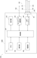
- FIG. 2 is a block diagram of a control system of a smartphone forming the nebulizer system.
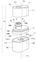
- FIG. 2 is a diagram showing an oblique view of the nebulizer head of the nebulizer system in an exploded state.
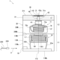
- FIG. 3 is a diagram schematically showing the internal structure of the assembled atomizer head as viewed from the side.
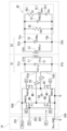
- FIG. 3 is a diagram illustrating the entire electrical circuitry included in the atomizer head.
- FIG. 6 is a diagram showing a modification of the electric circuit shown in FIG. 5; 7(A), FIG. 7(B), and FIG.
- FIG. 7(C) are diagrams showing a control flow by a control unit included in the smartphone.
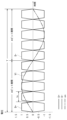
- FIG. 3 is a diagram illustrating the relationship between a control signal having a square waveform that the smartphone outputs to the nebulizer head and an alternating current voltage having a sinusoidal waveform created using the control signal in the nebulizer head.
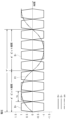
- FIG. 9 is a diagram showing an aspect in which the frequency of the AC voltage having the sinusoidal waveform in FIG. 8 is changed.
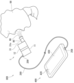
- FIG. 3 is a diagram showing how the nebulizer system is used by a user.
- FIG. 1 shows a schematic configuration of a nebulizer system 800 according to an embodiment of the present invention.
- This nebulizer system 800 is a nebulizer system that atomizes and ejects liquid, and includes a smartphone 400 as a computer device, and an atomizer head 1 directly connected to the smartphone 400 via a USB cable 200.
- the USB cable 200 has male USB connectors 208 and 209 at both ends, respectively.
- the USB connector 208 is detachably connected to a female USB connector 491 provided on the smartphone 400
- the USB connector 209 is detachably connected to a female USB connector 19 provided on the sprayer head 1. It has become so.
- the smartphone 400 is a general commercially available smartphone in which nebulizer application software (computer program) is installed to cause the nebulizer head 1 to perform a spraying operation as described below.
- nebulizer application software computer program
- the smartphone 400 includes a main body 400M, a control section 410, a memory 411, a display 420, an operation section 430, and a network communication section mounted on the main body 400M. 480, a USB interface 490, and a power supply section 499.
- the control unit 410 includes a CPU (Central Processing Unit) and its auxiliary circuit, controls each part of the smartphone 400, and executes the processing described below according to the program and data stored in the memory 411.
- CPU Central Processing Unit
- the memory 411 includes a RAM (Random Access Memory) used as a work area necessary for executing programs in the control unit 410, and a ROM (Read Only) for storing basic programs to be executed in the control unit 410. Memory). Furthermore, a semiconductor memory (such as a memory card) may be used as a storage medium of an auxiliary storage device to supplement the storage area of the memory 411.
- RAM Random Access Memory
- ROM Read Only
- the display device 420 is composed of an LCD (Liquid Crystal Display), and is controlled by the control unit 410 to display a predetermined image on the display screen.
- LCD Liquid Crystal Display
- the operation unit 430 includes a touch pad (not shown) superimposed on the display screen of the display 420, and inputs an operation signal indicating an operation by the user to the control unit 410.
- the display 420 and the touch pad constitute a known touch panel.
- the network communication unit 480 transmits information from the control unit 410 to another device (for example, a server not shown) via the network 900. Additionally, information from other devices is received via the network 900 and passed to the control unit 410.
- another device for example, a server not shown
- the USB interface 490 uses the information from the control unit 410 as a signal conforming to the USB standard to connect the female type USB connector 491 provided on the end wall 400Me (see FIG. 1) of the main body 400M and the USB connector 208 connected thereto. It is output to the outside, in this example to the atomizer head 1, through a USB cable 200 that has a USB cable 200.
- the signal according to the USB standard is a direct current voltage (DC5V) outputted via the Vbus line 201 and GND line 204 of the USB cable 200, and the D+ line 202 and D- line 203 of the USB cable 200. It includes control signals (D+ signal and D- signal) having a square waveform outputted through the D+ signal and the D- signal.
- the D+ signal and the D- signal are differential signals.
- the Vbus line 201 is capable of supplying a maximum current of 500 mA at DC5V.
- the power supply section 499 includes a rechargeable secondary battery (for example, a lithium ion battery).
- the power supply section 499 supplies power to each section mounted on the main body 400M, including the control section 410, memory 411, display 420, operation section 430, network communication section 480, and USB interface 490.
- FIG. 3 shows the atomizer head 1 in a disassembled state viewed from an angle.
- the sprayer head 1 is roughly divided into a main body 11 and a spray unit 12 attached to the main body 11.
- the main body casing 11M as the first casing forming the main body 11 has an elliptical planar shape (having a long axis 11A extending from the front left to the back right in FIG. 3), and has a vertical axis 11C. It has a columnar outer shape extending in the direction (in this example, the vertical direction).
- a recess 11K1 having a substantially short cylindrical outer shape is provided in the center of the upper wall 11Mt of the main body casing 11M (through which the vertical axis 11C passes) as an element for detachably attaching the main body 11 and the spray unit 12. ing.
- the recessed portion 11K1 has azimuth grooves 11K1e, 11K1e, 11K1e expanded radially outward in portions corresponding to specific directions (in this example, three directions at 120° intervals) around the vertical axis 11C. have.
- the spray unit 12 includes a base casing 30M having the same oval planar shape as the main casing 11M, and a cover member 31 that covers the base casing 30M.
- the cover member 31 is removably fitted into the base housing 30M in the direction of the vertical axis 11C (in this example, from above).
- the base housing 30M and the cover member 31 constitute a mounting housing 30 as a second housing.
- the base casing 30M has an upper accommodating portion 30Ma that protrudes upward in a cylindrical shape at a portion eccentric to the left front side from the vertical axis 11C.
- the upper accommodating section 30Ma accommodates a horn vibrator 40 as a vibrating section suitable for atomizing a liquid to be sprayed (such as a chemical solution).
- the mesh member 20 is placed on the top surface 30Mt of the upper accommodating portion 30Ma in a state facing the horn vibrator 40.
- the mesh member 20 includes a sheet 21 including a mesh portion adapted to atomize the liquid, and a flange portion 22 supporting the periphery of the sheet 21.
- “Mesh part” means an element that has a plurality of fine through holes in a sheet (or plate material) and allows liquid to pass through these through holes to atomize liquid.
- the mesh member 20 is designed to be disposable after one use.
- the horn vibrator 40 and the mesh member 20 constitute the atomizing section 39.
- a convex portion 30K1 having a substantially short cylindrical outer shape is provided as an element for detachably attaching the main body 11 and the spray unit 12.
- the convex portion 30K1 has a shape corresponding to the concave portion 11K1 of the main body casing 11M. That is, the convex portion 30K1 has a substantially cylindrical shape, and has enlarged diameter portions (in this example, three directions at 120° intervals) that protrude outward in the radial direction at portions corresponding to specific directions (in this example, three directions at 120° intervals) around the vertical axis 11C. (not shown).
- the spray unit 12 base housing 30M
- main body 11 main housing 11M
- the convex portion 30K1 will move toward the concave portion 11K1.
- the main body 11 and the spray unit 12 are easily assembled together. Once the main body 11 and the spray unit 12 are assembled, the assembled state is maintained by the frictional force between the concave portion 11K1 and the convex portion 30K1. Note that if the user applies a force that exceeds the frictional force to separate the spray unit 12 from the main body 11 in the direction of the vertical axis 11C, the spray unit 12 can be easily removed from the main body 11.
- the cover member 31 has the same oval planar shape as the base housing 30M, and has a cylindrical outer shape extending in the direction of the vertical axis 11C.
- a circular opening 31o is provided in a portion of the top wall 31t of the cover member 31 that is eccentric to the left front side from the vertical axis 11C.
- the edge of the opening 31o presses the flange portion 22 of the mesh member 20 in the direction of the vertical axis 11C (in this example, from above).
- the sheet 21 including the mesh portion is positioned relative to the horn vibrator 40.
- a mouthpiece 80 serving as a pipe member is detachably attached to the opening 31o from the outside of the cover member 31, as shown in FIG. 10, for example.
- the cover member 31 has a lid portion 31a that can be opened and closed by a hinge on a portion of the top wall 31t that corresponds to the back right side of the opening 31o, and a lid portion 31a that can be opened and closed by a hinge, and a lid portion 31a that can be opened and closed directly below the lid portion 31a. It has a liquid reservoir 17 as a liquid supply section provided at a position. With the cover member 31 attached to the base housing 30M, the user can temporarily open the lid portion 31a and pour the liquid into the liquid reservoir 17.
- FIG. 4 schematically shows the internal structure of the integrally assembled atomizer head 1 viewed from the side.
- a power transmission coil unit 61 and a circuit board 60 connected to the power transmission coil unit 61 by wirings 63a and 63b are mounted and housed in a main body housing 11M.
- the power transmission coil unit 61 includes a pole piece 64 made of a substantially cylindrical magnetic material, and a power transmission coil L1 as a first coil wound around the pole piece 64 and disposed around the pole piece 64.
- the power transmission coil unit 61 is arranged on the side facing the spray unit 12 along the upper wall 11Mt of the main body case 11M.
- the power transmission coil L1 is arranged along the inside of the upper wall 11Mt forming the main body casing 11M in a region surrounding the recess 11K1 centered on the vertical axis 11C.
- a first capacitor C1 shown in FIG. 5 is connected in parallel to the power transmission coil L1.
- Power transmission coil L1 and first capacitor C1 constitute a first resonant circuit 51.
- the first capacitor C1 is attached to the power transmission coil unit 61, but it may be mounted on the circuit board 60.
- the circuit board 60 shown in FIG. 4 is equipped with a female type USB connector 19 and a conversion circuit 50 to be described later, and is arranged along the inside of the bottom wall 11Mb forming the main body casing 11M. .
- the USB connector 19 penetrates the side wall 11Ms of the main body casing 11M and opens toward the outside.
- a male USB connector 209 of a USB cable 200 can be connected to this USB connector 19 by being inserted in the direction indicated by arrow X in FIG.
- the spray unit 12 has a horn oscillator 40 and a power receiving coil unit 71 connected to the horn oscillator 40 via wiring 73a, 73b mounted and housed in a mounting casing 30 (in particular, a base casing 30M). ing.
- the horn vibrator 40 includes a vibrating surface 43 disposed horizontally upward, an ultrasonic vibrator 41 disposed at a position spaced downward from the vibrating surface 43, and the ultrasonic vibrator 41 and the vibrating surface 43.
- a horn 42 is arranged between the ultrasonic vibrator 41 and the ultrasonic vibrator 41 to amplify the vibration and transmit the vibration to the vibration surface 43.
- the power receiving coil unit 71 includes a pole piece 74 made of a substantially cylindrical magnetic material, and a power receiving coil L2 as a second coil wound around the pole piece 74 and disposed around the pole piece 74.
- the power receiving coil unit 71 is arranged on the side facing the main body 11 along the inside of the bottom wall 30Mb of the base housing 30M.
- the power receiving coil L2 is electromagnetically coupled to the power transmitting coil L1.
- a second capacitor C2 shown in FIG. 5 is connected in parallel to the power receiving coil L2.
- Power receiving coil L2 and second capacitor C2 constitute a second resonant circuit 52.
- the second capacitor C2 is attached to the power receiving coil unit 71, but may be attached to the horn vibrator 40.
- the power transmitting coil L1 and the power receiving coil L2 are sandwiched between the upper wall 11Mt forming the main body case 11M and the bottom wall 30Mb forming the mounting case 30. are arranged in mutually corresponding areas. Therefore, during operation, the power for driving the horn vibrator 40 is transferred from the power transmitting coil L1 of the first resonant circuit 51 to the power receiving coil L2 of the second resonant circuit 52, in other words, from the main body 11 to the spray unit 12.
- the wireless power transmission method using magnetic coupling is used to efficiently transmit power.
- the power for driving the horn vibrator 40 is transmitted from the main body 11 to the spray unit 12 using the wireless power transmission method, so that the main body 11 (the main body housing 11M) and the spray unit 12 (the mounting housing 30) can be detachably separated as in this example.
- the main body 11 and the spray unit 12 are separated, for example, the base casing 30M and the cover member 31 of the spray unit 12 can be washed with water separately from the main body 11.
- the liquid is transferred from the spray unit 12 (mounting housing 30) to the main body 11 (main housing 11M) by the outer wall of the spray unit 12 (particularly the bottom wall 30Mb of the base housing 30M). Movement is prohibited. Therefore, a situation in which the liquid moves to the main body 11 and the circuit board 60 (for example, the conversion circuit 50 described later) breaks down is prevented. Furthermore, it is possible to prevent the liquid from moving from the main body 11 to the smartphone 400 via the USB cable 200 and causing the smartphone 400 to malfunction.
- FIG. 5 illustrates the entire electrical circuit included in the atomizer head 1.
- the electrical circuit of the atomizer head 1 can be broadly divided into a USB connector 19, a conversion circuit 50, a first resonance circuit 51, a second resonance circuit 52, and a horn vibrator 40 forming the atomization section 39. ing.
- the electrical circuit of the nebulizer head 1 does not include elements such as a processor, a display, an operating section, a battery, etc. other than the elements shown in FIG. 5 (or FIG. 6 described below).
- the USB connector 19 includes a Vbus line 201, a D+ line 202, a D- line 203, and a GND line 204, corresponding to the USB cable 200 (for simplicity, the codes of these lines are referred to as USB The numbers are the same as the lines in cable 200.)
- the first resonant circuit 51 generates an alternating current voltage V1 having a sine waveform between one end 51a and the other end 51b of the first resonant circuit 51.
- Power receiving coil L2 and second capacitor C2 constitute a second resonant circuit 52.
- the number of turns of the power receiving coil L2 is larger than the number of turns of the power transmitting coil L1, and in this example, the ratio of the number of turns of the power transmitting coil L1 to the number of turns of the power receiving coil L2 is set to approximately 1:3. .
- the second resonant circuit 52 changes the amplitude of the AC voltage V1 having a sine waveform generated by the first resonant circuit 51 to the ratio of the number of turns of the power transmitting coil L1 and the number of turns of the power receiving coil L2. Increase accordingly. Therefore, the second resonant circuit 52 generates an AC voltage V2 ( ⁇ 3 ⁇ V1) having a sine waveform between one end 52a and the other end 52b of the second resonant circuit 52.
- the ratio of the number of turns of the power transmitting coil L1 and the number of turns of the power receiving coil L2 is such that the amplitude of the AC voltage V2 having the sinusoidal waveform after the amplitude increase (boosting) by the second resonant circuit 52 is It is set in advance so as to be compatible with the horn vibrator 40 having the shape of 39.
- the amplitude of the alternating current voltage V2 to be applied to the horn vibrator 40 is scheduled to be within the range of several tens of volts to several tens of volts.
- an AC voltage V2 generated between one end 52a and the other end 52b of the second resonant circuit 52 is applied to the horn vibrator 40 represented by this equivalent circuit.
- the ultrasonic vibrator 41 of the horn vibrator 40 is driven, and the vibrating surface 43 shown in FIG.
- the horn vibrator 40 (the ultrasonic vibrator 41) is driven by the AC voltage V2 having a boosted sinusoidal waveform, the liquid can be efficiently atomized and ejected.
- FIG. 8 is created using control signals (D+ signal and D- signal) having a square waveform that the smartphone 400 outputs to the atomizer head 1 and those control signals (D+ signal and D- signal) within the atomizer head 1.
- the relationship between the AC voltage V1 and the AC voltage V1 having a sinusoidal waveform is shown.
- the vertical axis represents voltage and the horizontal axis represents time.
- the amplitude of the control signal and the amplitude of the AC voltage V1 are normalized to 1 and expressed.
- the minimum period in which the level can change according to the transmission speed defined by the USB standard is expressed as a 1-bit period tu.
- the control signal is the D+ signal (indicated by a solid line in FIG. 8) which becomes high level (+1) for m bit period, and then the D- signal (indicated by a solid line in FIG. 8). ) is at a high level (+1) for m bit periods, and is a signal that repeats in units of 2 m bit periods.
- An alternating current voltage V1 having a sinusoidal waveform as shown by a two-dot chain line is generated therein.
- the AC voltage V1 becomes a positive half-wave for the m-bit period when the D+ signal is at a high level (+1), and becomes a negative half-wave for the m-bit period when the D- signal is at a high level (+1).
- It becomes a half wave, and becomes a sine waveform that repeats a 2m bit period (that is, a period of 2m ⁇ tu) as one period T. Therefore, by setting the 2m bit period, the control unit 410 of the smartphone 400 can set the period T (in other words, the frequency f which is the reciprocal thereof) of the AC voltage V1 having a sine waveform.
- control unit 410 of the smartphone 400 can change the period T of the AC voltage V1 having a sine waveform by changing the value of m.
- the control unit 410 of the smartphone 400 can reduce the value of m by 1 to m', thereby changing the period T of the AC voltage V1 having a sine waveform to 2 m' bit period (FIG. 9). (denoted by T' in the middle).
- T' bit period
- the frequency f of the AC voltage V1 having a sinusoidal waveform can be increased.
- the frequency f of the AC voltage V1 having a sinusoidal waveform can be lowered.
- the transmission speeds defined by the USB standard include 1.5 Mbps (USB 1.0 standard), 12 Mbps (USB 1.1 standard), and 480 Mbps (USB 2.0 standard). If the transmission speed is high, the 1-bit period tu can be shortened, so the amount of change in the frequency f accompanying changing the value of m by 1 can be reduced. Therefore, if the frequency (for example, about 180 kHz) is for the horn transducer 40 (the ultrasonic transducer 41 thereof), substantially continuous frequency change (sweep) is possible in practice.
- nebulizer system operation It is assumed that the sprayer head 1 is assembled in advance as shown in FIG. 4, and that the liquid reservoir 17 of the spray unit 12 is filled with a liquid to be sprayed (typically, a chemical solution). Further, as shown in FIG. 10, it is assumed that a mouthpiece 80 is attached to the opening 31o of the spray unit 12.
- a user 99 who wishes to use the nebulizer head 1 connects the nebulizer head 1 to a smartphone 400 on which nebulizer application software has been installed in advance using a USB cable 200, as shown in FIG. This configures the nebulizer system 800.
- the user 99 operates the operation unit 430 (in this example, an icon displayed on the display 420) of the smartphone 400 to start the nebulizer application software. Subsequently, the user instructs the start of operation of the atomizer head 1 in the application software.
- the control unit 410 of the smartphone 400 first performs an initial search process, as shown in step S1 of FIG. 7(A).
- the control unit 410 monitors the current flowing between the Vbus line 201 and the GND line 204 via the USB interface 490, and connects the D+ line 202.
- the resonant frequency is searched for by changing the frequency of the control signals (D+ signal and D- signal) output through the D-line 203 (step S11).
- the control unit 410 determines the frequency f at which the most current flows between the Vbus line 201 and the GND line 204 as the resonance frequency fr (step S12).
- the control unit 410 controls the USB transmission so that the sprayer head 1 starts spraying at its resonance frequency fr (or near fr for stable control).
- signals according to the USB standard are provided.
- the control unit 410 supplies DC 5V via the USB interface 490 to the Vbus line 201 and the GND line 204 of the USB cable 200, and also supplies the D+ line 202 and the D- line of the USB cable 200.
- 203 to the atomizer head 1 with control signals having a square waveform (D+ and D- signals).
- the control signal is such that the D+ signal (indicated by a solid line in FIG.
- the control unit 410 sets the 2m bit period so that the first resonant circuit 51 in the atomizer head 1 generates an AC voltage V1 having a sinusoidal waveform at the resonant frequency fr (or near fr). Specifically, the value of m is set so that 2m ⁇ tu ⁇ 1/fr. In this way, the control unit 410 supplies a signal according to the USB standard, in which the value of m is set, to the atomizer head 1 via the USB interface 490.
- the conversion circuit 50 shown in FIG. to generate an AC voltage V1 having a sinusoidal waveform at a resonance frequency fr (or near fr).
- the AC voltage V1 having a sinusoidal waveform generated by the first resonant circuit 51 is boosted by the second resonant circuit 52 (including the power receiving coil L2 and the second capacitor C2) and becomes the AC voltage V2 having a sinusoidal waveform.
- the horn vibrator 40 of the atomizing section 39 shown in FIG. 4 is driven by the AC voltage V2 having a sinusoidal waveform, and the vibrating surface 43 vibrates.
- the liquid supplied to the gap 43g between the sheet 21 including the mesh portion and the vibration surface 43 of the horn vibrator 40 is atomized through the sheet 21 including the mesh portion, and as shown in FIG. It is ejected as an aerosol 90 through the piece 80.
- the control unit 410 of the smartphone 400 executes the frequency feedback process shown in FIG. 7(C).
- the control unit 410 monitors the current flowing between the Vbus line 201 and the GND line 204 via the USB interface 490, thereby controlling the current inside the atomizer head 1. It is determined whether the frequency f of the AC voltage V1 having a sinusoidal waveform generated by the first resonant circuit 51 has deviated from the initial resonant frequency fr0.
- the control unit 410 controls the first resonant circuit 51 in the sprayer head 1 based on the current flowing between the Vbus line 201 and the GND line 204.
- the frequency f of the AC voltage V1 having a sinusoidal waveform generated by the AC voltage V1 is corrected so that it matches the current resonance frequency fr of the horn vibrator 40 (Step S22).
- This frequency feedback process is repeatedly executed as needed during the spraying operation. That is, the control unit 410 determines whether the frequency f of the AC voltage V1 having a sinusoidal waveform generated by the first resonant circuit 51 in the atomizer head 1 has deviated from the previous resonant frequency fr0.
- control unit 410 controls the frequency f of the AC voltage V1 having a sine waveform generated by the first resonant circuit 51 in the sprayer head 1 to match the frequency f of the horn oscillator.
- the frequency f is corrected to match the current resonance frequency fr of 40 (step S22).
- the spraying operation continues unless an instruction is given to end the operation of the sprayer head 1 (NO in step S3 in FIG. 7(A)).
- the operation unit 430 in this example, the icon displayed on the display 420 of the smartphone 400 to instruct the end of the operation of the sprayer head 1 (YES in step S3 of FIG. 7(A)
- the control unit 410 stops supplying the signal to the atomizer head 1 in accordance with the USB standard. This causes the atomizer head 1 to complete the atomizing operation.
- a timer setting may be enabled on the nebulizer application software of the smartphone 400, and the spraying operation may be automatically ended when a predetermined spraying operation time is completed.
- this nebulizer system 800 the user 99 can use the nebulizer head 1 to perform a nebulizing operation.
- a controller including a processor
- the nebulizer head 1 also does not include a processor. Therefore, this nebulizer system 800 can be configured compactly with a small number of parts.
- the atomizing section 39 is of a mesh type, it is relatively compact and can be driven with relatively low electric power. Therefore, it is suitable for downsizing the nebulizer head 1 and configuring the nebulizer system 800 compactly.
- an H-bridge type conversion circuit 50A is provided instead of the conversion circuit 50.
- a PMOS transistor M4 and an N-channel field effect (NMOS) transistor M2 are connected in series in this order between the Vbus line 201 and the GND line 204, and a PMOS transistor M5 and The NMOS transistor M3 is connected in series in this order.
- a D+ line 202 is connected to the gate of the PMOS transistor M4 and the gate of the NMOS transistor M2, respectively, and a D+ signal is applied during operation.
- a D- line 203 is connected to the gate of the PMOS transistor M5 and the gate of the NMOS transistor M3, respectively, and a D- signal is applied during operation.
- the PMOS transistor M4 and the NMOS transistor M3 located at diagonal positions (top left and bottom right) in FIG. Repeat off.
- the NMOS transistor M2 and the PMOS transistor M5 which are in opposite phases to that phase and are located at different diagonal positions (lower left and upper right) in FIG. It alternates on and off depending on the phase.
- the first resonant circuit 51 generates an AC voltage V1A having a sine waveform between one end 51a and the other end 51b of the first resonant circuit 51.
- the amplitude of this AC voltage V1A is approximately twice the amplitude of AC voltage V1 shown in FIG. Accordingly, the amplitude of the AC voltage V2A having a sinusoidal waveform generated by the second resonant circuit 52 also becomes approximately twice the amplitude of the AC voltage V2 shown in FIG. Therefore, it can be preferably applied when the horn vibrator 40 forming the atomizing section 39 is of a type (specification) that should be driven at a relatively high voltage.
- the method for transmitting power for driving the horn vibrator 40 from the main body 11 to the spray unit 12 in the sprayer head 1 is a wireless power transmission method.
- the method for transmitting power for driving the horn vibrator 40 from the main body 11 to the spray unit 12 may be a wired power transmission method.
- the wired power transmission method for example, in the sprayer head 1, the main housing 11M of the main body 11 and the base housing 30M of the spray unit 12 are integrated into an integrated housing, and a conversion circuit 50 shown in FIG. 5 is generated.
- the atomizer head 1 may be applied to the horn vibrator 40 through wiring.
- the housing of the atomizer head 1 can be simplified, and the configuration of the electric circuit of the atomizer head 1 can be simplified. Therefore, the atomizer head 1 can be constructed compactly with fewer parts.
- the electrical circuit of the atomizer head 1 did not include any elements other than those shown in FIG. 5 or 6.
- the circuit board 60 of the sprayer head 1 may be equipped with an IC (integrated circuit) that has a function of sending back to the smartphone 400 that the USB communication between the smartphone 400 and the sprayer head 1 has been established.
- an LED light emitting diode
- It may also be equipped with a display.
- this indicator lights up during a period when a signal (in particular, a control signal) conforming to the USB standard is being supplied from the smartphone 400 to the atomizer head 1 to indicate that the signal is being supplied, and remains off during other periods. It is desirable to indicate that the signal supply is stopped.
- a signal in particular, a control signal
- the main body 11 (the circuit board 60 thereof) is equipped with a female type USB connector 19, and the male type USB connector 209 of the USB cable 200 is connected to this USB connector 19. .
- One end of the USB cable 200 is directly attached to the circuit board 60 (conversion circuit 50 or 50A thereof) by soldering or the like without intervening the USB connectors 19, 209, and the USB cable 200 is connected from the main body 11 (main body case 11M).
- a structure in which the USB cable is directly exposed may also be used (USB cable directly exposed structure).
- the sprayer head 1 (the main body 11 and the spray unit 12) has an oval planar shape, but the present invention is not limited to this.
- the planar shape of the atomizer head 1 may be an ellipse, a circle, a square with rounded corners (a square with rounded corners), or the like.
- the nebulizer system 800 includes the smartphone 400 as a computer device capable of supplying a signal in accordance with the USB standard via a USB cable, but the present invention is not limited to this.
- the smartphone 400 for example, a PDA (Personal Digital Assistant), a tablet terminal, a personal computer, etc. may be provided.
Landscapes
- Health & Medical Sciences (AREA)
- Engineering & Computer Science (AREA)
- Life Sciences & Earth Sciences (AREA)
- Animal Behavior & Ethology (AREA)
- Anesthesiology (AREA)
- Biomedical Technology (AREA)
- Heart & Thoracic Surgery (AREA)
- Hematology (AREA)
- Veterinary Medicine (AREA)
- Public Health (AREA)
- General Health & Medical Sciences (AREA)
- Pulmonology (AREA)
- Bioinformatics & Cheminformatics (AREA)
- Mechanical Engineering (AREA)
- Special Spraying Apparatus (AREA)
- Apparatuses For Generation Of Mechanical Vibrations (AREA)
Abstract
Description
液体を霧化して噴出するネブライザシステムであって、
USBケーブルを介してUSB規格に従う信号を供給可能なコンピュータ装置を備え、
上記コンピュータ装置は、USBケーブルのVbusラインとGNDラインとを介して直流電圧を供給し、かつ、上記USBケーブルのD+ラインとD-ラインとを介して方形波形を有する制御信号を供給し、
上記コンピュータ装置に上記USBケーブルによって直接接続された噴霧器ヘッドを備え、
上記噴霧器ヘッドは、
第1のコイルと第1のキャパシタとを含む第1の共振回路と、
上記第1の共振回路に上記直流電圧を上記制御信号に応じて断続的に又は交互に極性反転させて印加して、正弦波形を有する交流電圧を発生させる変換回路と、
上記正弦波形を有する交流電圧によって駆動され、液体を霧化して噴出する霧化部とを含む
ことを特徴とする。
上記噴霧器ヘッドは、さらに、上記第1のコイルに電磁的に結合された第2のコイルと第2のキャパシタとを含む第2の共振回路を含み、
上記第1の共振回路から上記第2の共振回路へ、上記霧化部を駆動するための電力がワイヤレス電力伝送方式で伝送される
ことを特徴とする。
上記噴霧器ヘッドは、
上記第1の共振回路と上記変換回路とを搭載した第1の筐体と、
上記第2の共振回路と上記霧化部とを搭載した第2の筐体と
を、互いに着脱可能に備え、
上記第2の筐体が有する外壁によって、上記第2の筐体から上記第1の筐体への上記液体の移動が禁止される
ことを特徴とする。
上記第1のコイルの巻数に比して上記第2のコイルの巻数が多くなっており、
上記第2の共振回路は、上記第1の共振回路が発生した上記正弦波形を有する交流電圧の振幅を、上記第1のコイルの巻数と上記第2のコイルの巻数との比に応じて増大させ、
上記霧化部は、上記第2の共振回路による振幅増大後の上記正弦波形を有する交流電圧によって駆動される
ことを特徴とする。
上記霧化部は、
上記正弦波形を有する交流電圧を用いて動作する、振動面を有するホーン振動子と、
上記振動面に対向して配置されたメッシュ部を有するメッシュ部材とを含み、
動作時に、上記振動面と上記メッシュ部との間に供給された液体を、上記メッシュ部を通して霧化するようになっている
ことを特徴とする。
上記制御信号をなすD+信号とD-信号が、上記USB規格が定める伝送速度に応じてレベル変化し得る最小の期間を1ビット期間とし、mを自然数としたとき、
上記制御信号は、上記D+信号がmビット期間だけ高レベルになったのに続いて上記D-信号がmビット期間だけ高レベルになり、2mビット期間を単位として繰り返す信号である
ことを特徴とする。
上記コンピュータ装置は、上記制御信号の上記mの値を変化させることによって、上記交流電圧の周期を変化させるようになっている
ことを特徴とする。
図1は、この発明の一実施形態のネブライザシステム800の概略構成を示している。このネブライザシステム800は、液体を霧化して噴出するネブライザシステムであって、コンピュータ装置としてのスマートフォン400と、このスマートフォン400にUSBケーブル200によって直接接続された噴霧器ヘッド1とを備えている。この例では、USBケーブル200は、両端にそれぞれ雄タイプのUSBコネクタ208,209を有している。USBコネクタ208は、スマートフォン400に設けられた雌タイプのUSBコネクタ491に着脱自在に接続され、また、USBコネクタ209は、噴霧器ヘッド1に設けられた雌タイプのUSBコネクタ19に着脱自在に接続されるようになっている。
スマートフォン400は、一般的な市販のスマートフォンにネブライザ用アプリケーションソフトウェア(コンピュータプログラム)をインストールすることによって、噴霧器ヘッド1に対して後述の噴霧動作を行わせるようにしたものである。
図3は、噴霧器ヘッド1を分解状態で斜めから見たところを示している。この噴霧器ヘッド1は、大別して、本体11と、この本体11に取り付られる噴霧ユニット12とを備えている。
図8は、スマートフォン400が噴霧器ヘッド1へ出力する方形波形を有する制御信号(D+信号とD-信号)と、噴霧器ヘッド1内でそれらの制御信号(D+信号とD-信号)を用いて作成される正弦波形を有する交流電圧V1との関係を示している。図8において、縦軸は電圧を表し、横軸は時間を表している。縦軸では、制御信号の振幅と交流電圧V1の振幅が1に正規化して表されている。横軸では、USB規格が定める伝送速度に応じてレベル変化し得る最小の期間が、1ビット期間tuとして表されている。この例では、mを自然数としたとき、制御信号は、D+信号(図8中に実線で示す)がmビット期間だけ高レベル(+1)になったのに続いてD-信号(図8中に破線で示す)がmビット期間だけ高レベル(+1)になり、2mビット期間を単位として繰り返す信号になっている。なお、作図の便宜上、図8ではm=5として描かれているが、これに限られるものではない。D+信号とD-信号とは差動信号であるから、互いに正負が逆になる変化をしている。このような制御信号(D+信号とD-信号)が図5中に示した変換回路50に印加されると、第1の共振回路51の一端51aと他端51bとの間には、図8中に2点鎖線で示すような正弦波形を有する交流電圧V1が発生する。すなわち、交流電圧V1は、D+信号が高レベル(+1)になっているmビット期間については正の半波となり、D-信号が高レベル(+1)になっているmビット期間については負の半波となり、2mビット期間(すなわち、2m×tuの期間)を1周期Tとして繰り返す正弦波形となる。したがって、スマートフォン400の制御部410は、2mビット期間を設定することによって、正弦波形を有する交流電圧V1の周期T(言い換えれば、その逆数である周波数f)を設定することができる。また、スマートフォン400の制御部410は、mの値を変化させることによって、正弦波形を有する交流電圧V1の周期Tを変化させることができる。例えば、スマートフォン400の制御部410は、図9に例示するように、mの値を1だけ減じてm′にすれば、正弦波形を有する交流電圧V1の周期Tを2m′ビット期間(図9中にT′で表す)に短くすることができる。このように、mの値を減じることによって、正弦波形を有する交流電圧V1の周波数fを高くすることができる。逆に、mの値を増やすことによって、正弦波形を有する交流電圧V1の周波数fを低くすることができる。
噴霧器ヘッド1は、予め図4に示したように組み立てられ、噴霧ユニット12の液溜め17に、噴霧すべき液体(典型的には、薬液)が入れられているものとする。また、図10中に示すように、その噴霧ユニット12の開口31oに、マウスピース80が装着されているものとする。噴霧器ヘッド1を使用しようとするユーザ99は、図10中に示すように、噴霧器ヘッド1と、予めネブライザ用アプリケーションソフトウェアがインストールされたスマートフォン400とを、USBケーブル200によって接続する。これにより、ネブライザシステム800が構成される。
上の例では、図5に示した電気回路では、動作時に、変換回路50をなすPMOSトランジスタM1がD+信号に応じて断続的にオンして、第1の共振回路51の一端51aと他端51bとの間に直流電圧(Vbus=5V)が断続的に印加されるものとした。しかしながら、これに限られるものではなく、図6に示す電気回路のように、動作時に、第1の共振回路51の一端51aと他端51bとの間に直流電圧(Vbus=5V)が交互に極性反転させて印加されるものとしてもよい。
11,400M 本体
11M 本体筐体
12 噴霧ユニット
20 メッシュ部材
21 シート
30 装着用筐体
30M ベース筐体
31 カバー部材
40 ホーン振動子
50,50A 変換回路
51 第1の共振回路
52 第2の共振回路
200 USBケーブル
400 スマートフォン
410 制御部
800 ネブライザシステム
Claims (7)
- 液体を霧化して噴出するネブライザシステムであって、
USBケーブルを介してUSB規格に従う信号を供給可能なコンピュータ装置を備え、
上記コンピュータ装置は、USBケーブルのVbusラインとGNDラインとを介して直流電圧を供給し、かつ、上記USBケーブルのD+ラインとD-ラインとを介して方形波形を有する制御信号を供給し、
上記コンピュータ装置に上記USBケーブルによって直接接続された噴霧器ヘッドを備え、
上記噴霧器ヘッドは、
第1のコイルと第1のキャパシタとを含む第1の共振回路と、
上記第1の共振回路に上記直流電圧を上記制御信号に応じて断続的に又は交互に極性反転させて印加して、正弦波形を有する交流電圧を発生させる変換回路と、
上記正弦波形を有する交流電圧によって駆動され、液体を霧化して噴出する霧化部とを含む
ことを特徴とするネブライザシステム。 - 請求項1に記載のネブライザシステムにおいて、
上記噴霧器ヘッドは、さらに、上記第1のコイルに電磁的に結合された第2のコイルと第2のキャパシタとを含む第2の共振回路を含み、
上記第1の共振回路から上記第2の共振回路へ、上記霧化部を駆動するための電力がワイヤレス電力伝送方式で伝送される
ことを特徴とするネブライザシステム。 - 請求項2に記載のネブライザシステムにおいて、
上記噴霧器ヘッドは、
上記第1の共振回路と上記変換回路とを搭載した第1の筐体と、
上記第2の共振回路と上記霧化部とを搭載した第2の筐体と
を、互いに着脱可能に備え、
上記第2の筐体が有する外壁によって、上記第2の筐体から上記第1の筐体への上記液体の移動が禁止される
ことを特徴とするネブライザシステム。 - 請求項2または3に記載のネブライザシステムにおいて、
上記第1のコイルの巻数に比して上記第2のコイルの巻数が多くなっており、
上記第2の共振回路は、上記第1の共振回路が発生した上記正弦波形を有する交流電圧の振幅を、上記第1のコイルの巻数と上記第2のコイルの巻数との比に応じて増大させ、
上記霧化部は、上記第2の共振回路による振幅増大後の上記正弦波形を有する交流電圧によって駆動される
ことを特徴とするネブライザシステム。 - 請求項1から3までのいずれか一つに記載のネブライザシステムにおいて、
上記霧化部は、
上記正弦波形を有する交流電圧を用いて動作する、振動面を有するホーン振動子と、
上記振動面に対向して配置されたメッシュ部を有するメッシュ部材とを含み、
動作時に、上記振動面と上記メッシュ部との間に供給された液体を、上記メッシュ部を通して霧化するようになっている
ことを特徴とするネブライザシステム。 - 請求項1から3までのいずれか一つに記載のネブライザシステムにおいて、
上記制御信号をなすD+信号とD-信号が、上記USB規格が定める伝送速度に応じてレベル変化し得る最小の期間を1ビット期間とし、mを自然数としたとき、
上記制御信号は、上記D+信号がmビット期間だけ高レベルになったのに続いて上記D-信号がmビット期間だけ高レベルになり、2mビット期間を単位として繰り返す信号である
ことを特徴とするネブライザシステム。 - 請求項6に記載のネブライザシステムにおいて、
上記コンピュータ装置は、上記制御信号の上記mの値を変化させることによって、上記交流電圧の周期を変化させるようになっている
ことを特徴とするネブライザシステム。
Priority Applications (3)
| Application Number | Priority Date | Filing Date | Title |
|---|---|---|---|
| CN202380040215.3A CN119325398A (zh) | 2022-07-21 | 2023-02-03 | 雾化器系统 |
| DE112023001340.3T DE112023001340T5 (de) | 2022-07-21 | 2023-02-03 | Inhalatorsystem |
| US18/924,010 US20250041539A1 (en) | 2022-07-21 | 2024-10-23 | Nebulizer system |
Applications Claiming Priority (2)
| Application Number | Priority Date | Filing Date | Title |
|---|---|---|---|
| JP2022116661A JP2024014084A (ja) | 2022-07-21 | 2022-07-21 | ネブライザシステム |
| JP2022-116661 | 2022-07-21 |
Related Child Applications (1)
| Application Number | Title | Priority Date | Filing Date |
|---|---|---|---|
| US18/924,010 Continuation US20250041539A1 (en) | 2022-07-21 | 2024-10-23 | Nebulizer system |
Publications (1)
| Publication Number | Publication Date |
|---|---|
| WO2024018656A1 true WO2024018656A1 (ja) | 2024-01-25 |
Family
ID=89617567
Family Applications (1)
| Application Number | Title | Priority Date | Filing Date |
|---|---|---|---|
| PCT/JP2023/003600 Ceased WO2024018656A1 (ja) | 2022-07-21 | 2023-02-03 | ネブライザシステム |
Country Status (5)
| Country | Link |
|---|---|
| US (1) | US20250041539A1 (ja) |
| JP (1) | JP2024014084A (ja) |
| CN (1) | CN119325398A (ja) |
| DE (1) | DE112023001340T5 (ja) |
| WO (1) | WO2024018656A1 (ja) |
Citations (3)
| Publication number | Priority date | Publication date | Assignee | Title |
|---|---|---|---|---|
| KR101228598B1 (ko) * | 2012-06-28 | 2013-01-31 | 김창덕 | 초음파 디퓨져 |
| JP3199314U (ja) * | 2012-05-03 | 2015-08-20 | スタムフォード・ディバイセズ・リミテッド | 噴霧器 |
| CN204943782U (zh) * | 2015-06-08 | 2016-01-06 | 东莞市慧衍电子有限公司 | 一种雾化加湿器的控制电路及雾化加湿器 |
-
2022
- 2022-07-21 JP JP2022116661A patent/JP2024014084A/ja active Pending
-
2023
- 2023-02-03 DE DE112023001340.3T patent/DE112023001340T5/de active Pending
- 2023-02-03 WO PCT/JP2023/003600 patent/WO2024018656A1/ja not_active Ceased
- 2023-02-03 CN CN202380040215.3A patent/CN119325398A/zh active Pending
-
2024
- 2024-10-23 US US18/924,010 patent/US20250041539A1/en active Pending
Patent Citations (3)
| Publication number | Priority date | Publication date | Assignee | Title |
|---|---|---|---|---|
| JP3199314U (ja) * | 2012-05-03 | 2015-08-20 | スタムフォード・ディバイセズ・リミテッド | 噴霧器 |
| KR101228598B1 (ko) * | 2012-06-28 | 2013-01-31 | 김창덕 | 초음파 디퓨져 |
| CN204943782U (zh) * | 2015-06-08 | 2016-01-06 | 东莞市慧衍电子有限公司 | 一种雾化加湿器的控制电路及雾化加湿器 |
Also Published As
| Publication number | Publication date |
|---|---|
| US20250041539A1 (en) | 2025-02-06 |
| DE112023001340T5 (de) | 2024-12-24 |
| JP2024014084A (ja) | 2024-02-01 |
| CN119325398A (zh) | 2025-01-17 |
Similar Documents
| Publication | Publication Date | Title |
|---|---|---|
| RU155196U1 (ru) | Распылитель | |
| JP2002537985A (ja) | 圧電振動器を用いて液体を噴霧化する制御システム | |
| GB2603858A (en) | A hookah device | |
| AU2021478130B2 (en) | An apparatus for transmitting ultrasonic waves | |
| CN211050546U (zh) | 雾化器 | |
| US20240058550A1 (en) | Nebulizer | |
| JP2024014084A (ja) | ネブライザシステム | |
| IL310598A (en) | Nicotine delivery device | |
| CN206714086U (zh) | 一种超声波电子烟电路 | |
| CN113318307B (zh) | 一种雾化器 | |
| CN223437904U (zh) | 一种雾化器、雾化主机和电子雾化设备 | |
| CN214042065U (zh) | 一种振镜独立运算结构 | |
| JP2023523665A (ja) | 振動子を含むエアロゾル生成装置及びその動作方法 | |
| CN117203876A (zh) | 供电系统和雾化器 | |
| JPS6230827B2 (ja) | ||
| CN109188948A (zh) | 一种无线型基于压电振动器的幅频可调振动触觉控制装置 | |
| US20250083186A1 (en) | Aerosol generating device with driving circuit matching the impedance of ultrasonic vibrator | |
| CN206224378U (zh) | 一种手环消息节能提示的系统 | |
| JPH08281165A (ja) | 超音波霧化装置 | |
| CN215531660U (zh) | 一种雾化器 | |
| CN109420225A (zh) | 雾化装置及其操作方法 | |
| JPH09253543A (ja) | 超音波霧化装置の駆動回路 | |
| JPS6029311B2 (ja) | 霧化装置 | |
| HK40108121A (en) | Mist inhaler devices for therapeutic delivery | |
| TW201309391A (zh) | 變頻式噴霧裝置及其噴霧方法 |
Legal Events
| Date | Code | Title | Description |
|---|---|---|---|
| 121 | Ep: the epo has been informed by wipo that ep was designated in this application |
Ref document number: 23842598 Country of ref document: EP Kind code of ref document: A1 |
|
| WWE | Wipo information: entry into national phase |
Ref document number: 202417080627 Country of ref document: IN |
|
| WWE | Wipo information: entry into national phase |
Ref document number: 112023001340 Country of ref document: DE |
|
| WWE | Wipo information: entry into national phase |
Ref document number: 202380040215.3 Country of ref document: CN |
|
| WWP | Wipo information: published in national office |
Ref document number: 202380040215.3 Country of ref document: CN |
|
| 122 | Ep: pct application non-entry in european phase |
Ref document number: 23842598 Country of ref document: EP Kind code of ref document: A1 |