WO2024018620A1 - Sensor-attached guide wire - Google Patents
Sensor-attached guide wire Download PDFInfo
- Publication number
- WO2024018620A1 WO2024018620A1 PCT/JP2022/028488 JP2022028488W WO2024018620A1 WO 2024018620 A1 WO2024018620 A1 WO 2024018620A1 JP 2022028488 W JP2022028488 W JP 2022028488W WO 2024018620 A1 WO2024018620 A1 WO 2024018620A1
- Authority
- WO
- WIPO (PCT)
- Prior art keywords
- sensor
- wire
- core wire
- coil body
- guide wire
- Prior art date
Links
- WABPQHHGFIMREM-UHFFFAOYSA-N lead(0) Chemical compound [Pb] WABPQHHGFIMREM-UHFFFAOYSA-N 0.000 description 86
- 238000005304 joining Methods 0.000 description 55
- 238000012986 modification Methods 0.000 description 17
- 230000004048 modification Effects 0.000 description 17
- 238000010586 diagram Methods 0.000 description 13
- 210000004204 blood vessel Anatomy 0.000 description 11
- 230000002093 peripheral effect Effects 0.000 description 9
- 125000006850 spacer group Chemical group 0.000 description 9
- 230000000694 effects Effects 0.000 description 8
- 238000004804 winding Methods 0.000 description 8
- 238000000034 method Methods 0.000 description 7
- 238000002834 transmittance Methods 0.000 description 7
- 239000000853 adhesive Substances 0.000 description 6
- 230000001070 adhesive effect Effects 0.000 description 6
- 229920001721 polyimide Polymers 0.000 description 5
- 239000009719 polyimide resin Substances 0.000 description 5
- 239000008280 blood Substances 0.000 description 4
- 210000004369 blood Anatomy 0.000 description 4
- 210000001124 body fluid Anatomy 0.000 description 4
- 239000010839 body fluid Substances 0.000 description 4
- 239000007767 bonding agent Substances 0.000 description 4
- 239000000463 material Substances 0.000 description 4
- 239000011347 resin Substances 0.000 description 4
- 229920005989 resin Polymers 0.000 description 4
- 208000031481 Pathologic Constriction Diseases 0.000 description 3
- 230000007423 decrease Effects 0.000 description 3
- -1 for example Substances 0.000 description 3
- 238000004519 manufacturing process Methods 0.000 description 3
- 238000000926 separation method Methods 0.000 description 3
- 229910000679 solder Inorganic materials 0.000 description 3
- 230000036262 stenosis Effects 0.000 description 3
- 208000037804 stenosis Diseases 0.000 description 3
- 230000036772 blood pressure Effects 0.000 description 2
- 230000002490 cerebral effect Effects 0.000 description 2
- 238000006073 displacement reaction Methods 0.000 description 2
- 238000003780 insertion Methods 0.000 description 2
- 230000037431 insertion Effects 0.000 description 2
- 229910052751 metal Inorganic materials 0.000 description 2
- 239000002184 metal Substances 0.000 description 2
- 239000007769 metal material Substances 0.000 description 2
- 229910001316 Ag alloy Inorganic materials 0.000 description 1
- RYGMFSIKBFXOCR-UHFFFAOYSA-N Copper Chemical compound [Cu] RYGMFSIKBFXOCR-UHFFFAOYSA-N 0.000 description 1
- BQCADISMDOOEFD-UHFFFAOYSA-N Silver Chemical compound [Ag] BQCADISMDOOEFD-UHFFFAOYSA-N 0.000 description 1
- 229910001128 Sn alloy Inorganic materials 0.000 description 1
- 208000007536 Thrombosis Diseases 0.000 description 1
- ATJFFYVFTNAWJD-UHFFFAOYSA-N Tin Chemical compound [Sn] ATJFFYVFTNAWJD-UHFFFAOYSA-N 0.000 description 1
- HCHKCACWOHOZIP-UHFFFAOYSA-N Zinc Chemical compound [Zn] HCHKCACWOHOZIP-UHFFFAOYSA-N 0.000 description 1
- WAIPAZQMEIHHTJ-UHFFFAOYSA-N [Cr].[Co] Chemical class [Cr].[Co] WAIPAZQMEIHHTJ-UHFFFAOYSA-N 0.000 description 1
- 230000002785 anti-thrombosis Effects 0.000 description 1
- 230000005540 biological transmission Effects 0.000 description 1
- 238000005219 brazing Methods 0.000 description 1
- 239000004020 conductor Substances 0.000 description 1
- 229910052802 copper Inorganic materials 0.000 description 1
- 239000010949 copper Substances 0.000 description 1
- 229920006332 epoxy adhesive Polymers 0.000 description 1
- PCHJSUWPFVWCPO-UHFFFAOYSA-N gold Chemical compound [Au] PCHJSUWPFVWCPO-UHFFFAOYSA-N 0.000 description 1
- 229910052737 gold Inorganic materials 0.000 description 1
- 239000010931 gold Substances 0.000 description 1
- 230000002209 hydrophobic effect Effects 0.000 description 1
- 229910001000 nickel titanium Inorganic materials 0.000 description 1
- 229920006122 polyamide resin Polymers 0.000 description 1
- 229920001225 polyester resin Polymers 0.000 description 1
- 239000004645 polyester resin Substances 0.000 description 1
- 229920005672 polyolefin resin Polymers 0.000 description 1
- 229920005749 polyurethane resin Polymers 0.000 description 1
- 239000000843 powder Substances 0.000 description 1
- 229920002050 silicone resin Polymers 0.000 description 1
- 229910052709 silver Inorganic materials 0.000 description 1
- 239000004332 silver Substances 0.000 description 1
- 239000010935 stainless steel Substances 0.000 description 1
- 229910001220 stainless steel Inorganic materials 0.000 description 1
- 229910052718 tin Inorganic materials 0.000 description 1
- 239000011135 tin Substances 0.000 description 1
- 238000003466 welding Methods 0.000 description 1
- 229910052725 zinc Inorganic materials 0.000 description 1
- 239000011701 zinc Substances 0.000 description 1
Images


Classifications
-
- A—HUMAN NECESSITIES
- A61—MEDICAL OR VETERINARY SCIENCE; HYGIENE
- A61B—DIAGNOSIS; SURGERY; IDENTIFICATION
- A61B5/00—Measuring for diagnostic purposes; Identification of persons
- A61B5/05—Detecting, measuring or recording for diagnosis by means of electric currents or magnetic fields; Measuring using microwaves or radio waves
- A61B5/053—Measuring electrical impedance or conductance of a portion of the body
- A61B5/0538—Measuring electrical impedance or conductance of a portion of the body invasively, e.g. using a catheter
Definitions
- the present invention relates to a guidewire with a sensor.
- Guidewires that guide catheters and the like inserted into living body lumens such as blood vessels include guidewires with sensors that have sensors attached to their distal ends.
- Patent Document 1 discloses a guidewire with a sensor, which has a housing including a sensor at its distal end.
- Patent Document 2 discloses a guide wire with a sensor that includes a sensor holder at the distal end for holding a sensor.
- the present invention has been made to solve at least part of the above-mentioned problems, and aims to provide a technique for improving torque transmittance at the distal end of a guidewire with a sensor.
- the present invention has been made to solve at least part of the above-mentioned problems, and can be realized as the following forms.
- a guide wire with a sensor is provided.
- This guide wire with a sensor is provided with a core wire, a first coil body surrounding the tip of the core wire, a tip that joins the tip of the core wire and the tip of the first coil body, and a sensor.
- a tubular member the tubular member surrounds the core wire, the distal end of the tubular member is disposed inside the proximal end of the first coil body, and the distal end of the tubular member and the It is joined to the base end of the first coil body.
- the distal end of the tubular member is disposed inside the proximal end of the first coil body, and the distal end of the tubular member and the proximal end of the first coil body are joined. Therefore, the central axis of the tubular member can be prevented from shifting from the central axis of the first coil body.
- the first coil body constitutes the outer shape of the distal end of the guide wire with a sensor
- the central axis of the first coil body corresponds to the central axis of the distal end of the guide wire with a sensor. , it is possible to suppress the center axis of the tubular member from shifting from the center axis of the guide wire with the sensor. Therefore, since the torque transmittance at the distal end of the sensor-equipped guide wire is improved, the operability of the sensor-equipped guide wire can be improved.
- the outer diameter of the proximal end portion of the first coil body may be larger than the outer diameter of the tubular member including the sensor.
- the sensor-equipped guide wire of the above embodiment further includes an inner coil body disposed between the first coil body and the core wire and surrounding a distal end portion of the core wire, the proximal end of the inner coil body being arranged between the first coil body and the core wire.
- the portion may be disposed inside the distal end portion of the tubular member.
- the sensor-equipped guide wire of the above embodiment further includes a second coil body surrounding the core wire on the proximal side of the first coil body, and the proximal end of the tubular member is connected to the second coil body.
- the proximal end of the tubular member and the distal end of the second coil body may be joined to each other. According to this configuration, it is possible to suppress the center axis of the tubular member from shifting from the center axis of the second coil body. Since the second coil body constitutes a part of the outer shape of the guide wire with a sensor, the central axis of the second coil body corresponds to a part of the central axis of the guide wire with a sensor.
- the outer diameter of the distal end portion of the second coil body may be larger than the outer diameter of the tubular member including the sensor.
- the present invention can be realized in various forms, such as a medical device including a guide wire with a sensor, a catheter including a guide wire with a sensor, a method for manufacturing a guide wire with a sensor, etc. be able to.
- FIG. 2 is an explanatory diagram illustrating the configuration of a guide wire with a sensor according to the first embodiment.
- FIG. 3 is an enlarged view of the connector assembly.
- FIG. 3 is a detailed illustration of the connector assembly, core wire and cable;
- FIG. 3 is a cross-sectional view showing each cross section of the proximal end portion of the guide wire with a sensor.
- FIG. 3 is an enlarged cross-sectional view of the sensor assembly.
- FIG. 3 is an explanatory diagram for explaining details of the configuration of a tubular member.
- FIG. 3 is an explanatory diagram for explaining details of the configuration of a sensor sheet. It is an explanatory view for explaining the winding process of a sensor sheet around a tubular member.
- FIG. 3 is an enlarged view of the vicinity of the sensor assembly. It is an explanatory view showing a schematic structure of a guide wire with a sensor of a 3rd embodiment.
- FIG. 7 is a sectional view showing a cross section of a guide wire with a sensor according to a fourth embodiment. It is an explanatory view showing a schematic structure of a guide wire with a sensor of a 5th embodiment.
- FIG. 1 is an explanatory diagram illustrating a cross-sectional configuration of a sensor-equipped guidewire 1 according to the first embodiment. Note that in FIG. 1, the sensor assembly 20 and the connector assembly 40 are shown externally.
- the sensor-equipped guide wire 1 of this embodiment is a device that is used by being inserted into a cerebral blood vessel, for example, and is capable of measuring the electrical resistance of body fluids such as blood flowing through the blood vessel. The electrical resistance detected by the sensor-equipped guide wire 1 is used, for example, to determine the type of thrombus that has occurred in a cerebral blood vessel.
- an axis passing through the center of the sensor-equipped guide wire 1 is represented by an axis O (dotted chain line).
- the central axis passing through the center of at least the core wire 10, the tubular member 22 (see FIG. 5), the first coil body 60, and the second coil body 70, which will be described later, of each member of the sensor-equipped guide wire 1 coincides with the axis O.
- the central axes passing through the centers of other members may be offset from the axis O.
- FIG. 1 shows XYZ axes that are orthogonal to each other.
- the X-axis corresponds to the axial direction of the sensor-equipped guide wire 1 (the insertion direction of the sensor-equipped guide wire 1)
- the Y-axis corresponds to the width direction of the sensor-equipped guide wire 1
- the Z-axis corresponds to the height of the sensor-equipped guide wire 1.
- the right side (+X-axis direction) of FIG. 1 is called the “distal side” of the guidewire 1 with sensor and each component
- the left side (-X-axis direction) of FIG. 1 is called the "base" of the guidewire 1 with sensor and each component. It is called the "end side”.
- the end located on the distal side and the vicinity thereof is referred to as the "distal end” or simply the “tip”, and the end located on the proximal side and the vicinity thereof is referred to as the "base”.
- ⁇ end'' or simply ⁇ proximal'' The distal end of the sensor-equipped guide wire 1 is the part that is inserted into the living body, and the proximal end is the part that is operated by an operator such as a doctor.
- the sensor-equipped guide wire 1 includes a core wire 10, a sensor assembly 20, a cable 30, and a connector assembly 40.
- the core wire 10 is a long member extending along the X-axis direction.
- the core wire 10 has, in order from the distal end to the proximal end, a distal end narrow diameter section 11, a taper section 12, a large diameter section 13, a reduced diameter section 14, and a proximal end narrow diameter section 15.
- the narrow end portion 11 is provided at the most distal end of the core wire 10, has a substantially cylindrical shape with a substantially constant outer diameter, and is the portion of the core wire 10 that has the smallest outer diameter.
- substantially constant has the same meaning as “approximately constant”, and means being approximately constant while allowing for fluctuations due to manufacturing errors and the like.
- the tapered portion 12 is provided between the narrow end portion 11 and the large diameter portion 13, and is a portion whose outer diameter gradually decreases from the proximal end toward the distal end.
- the large-diameter portion 13 is provided between the tapered portion 12 and the reduced-diameter portion 14 and is a substantially cylindrical portion having a larger outer diameter than the narrow-diameter tip portion 11 and the narrow-diameter proximal portion 15 .
- the reduced diameter portion 14 is provided between the large diameter portion 13 and the proximal narrow diameter portion 15, and is a portion whose outer diameter gradually decreases from the distal end side to the proximal end side.
- the narrow proximal diameter portion 15 is provided adjacent to the reduced diameter portion 14 from the proximal end side, and has a substantially cylindrical shape with a substantially constant outer diameter, and is a portion of the core wire 10 where the outer diameter is smaller than the large diameter portion 13. be. Note that the outer diameters, lengths in the axis O direction, and cross-sectional shapes of the narrow end portion 11, the tapered portion 12, the large diameter portion 13, the reduced diameter portion 14, and the narrow base portion 15 can be arbitrarily determined.
- the sensor assembly 20 is placed at the tip of the core wire 10.
- the sensor assembly 20 is a structure that includes a sensor array 24s (see FIG. 7) that measures the electrical resistance of body fluids such as blood flowing in blood vessels.
- the core wire 10 is inserted inside the sensor assembly 20 . Details of the sensor assembly 20 will be explained later with reference to FIGS. 5 to 8.
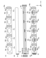
- the cable 30 has five lead wires 32a to 32e (see FIGS. 3(C) and 9(A) and 9(B)) extending along the core wire 10 to the proximal end of the core wire 10, and connects to the sensor assembly 20.
- the included sensor wiring 24c (see FIG. 5), which will be described later, and hollow electrodes 41a to 41e (see FIG. 2) included in the connector assembly 40, which will be described later, are electrically connected. Details of the cable 30 will be explained later with reference to FIGS. 3 and 9. Note that "electrically connected” means connected in a state where current can flow (a state where conduction is possible).
- the connector assembly 40 is located at the proximal end of the core wire 10.
- the connector assembly 40 is a structure for connecting to an external device that processes an output signal from a sensor array 24s (see FIG. 7), which will be described later. Inside the connector assembly 40, a portion of the base narrow diameter portion 15 of the core wire 10 and the cable 30 are arranged. Details of the connector assembly 40 will be explained below with reference to FIGS. 2 to 4.
- the sensor-equipped guide wire 1 includes a distal tip 50, a first coil body 60, a second coil body 70, an intermediate joining member 75, a tube 80, and a proximal joining member. 85.
- the tip 50 joins the tip of the core wire 10 and the tip of the first coil body 60.
- the tip 50 can be formed using any bonding agent, for example, metal solder such as silver solder, gold solder, zinc, Sn--Ag alloy, Au--Sn alloy, or adhesive such as epoxy adhesive.
- the first coil body 60 and the second coil body 70 are flexible, substantially cylindrical coil bodies having a substantially constant outer diameter from the proximal end to the distal end.
- the first coil body 60 is arranged to surround the tip of the core wire 10.
- the second coil body 70 is arranged so as to surround the core wire 10 and the cable 30 on the proximal side of the first coil body 60 .
- the second coil body 70 is arranged so as to surround the core wire 10 and the cable 30 on the proximal end side from the sensor assembly 20.
- the first coil body 60 and the second coil body 70 are joined to the sensor assembly 20.
- the first coil body 60 and the second coil body 70 are single-filament coils formed by winding one strand into a single thread.
- first coil body 60 and the second coil body 70 may be multi-filament coils formed by winding a plurality of wires into multiple threads, or may be a stranded wire formed by twisting a plurality of wires together. It may be a single stranded wire coil formed by winding a single wire, or a multi-stranded wire formed by using a plurality of stranded wires made by twisting multiple strands together and winding each strand into multiple threads. It may also be a coil.
- the outer diameter and inner diameter of the first coil body 60 and the second coil body 70 can be arbitrarily determined.
- the tube 80 is a substantially cylindrical tube having a substantially constant outer diameter from the proximal end to the distal end.
- the tube 80 is arranged so as to surround the core wire 10 and the cable 30 on the proximal side of the second coil body 70 .
- the tube 80 preferably has antithrombotic properties, flexibility, and biocompatibility, and can be formed from a resin material or a metal material.
- the resin material for example, polyimide resin, polyamide resin, polyolefin resin, polyester resin, polyurethane resin, silicone resin, fluororesin, etc. can be adopted.
- As the metal material for example, stainless steel such as SUS304, nickel titanium alloy, cobalt chromium alloy, etc. can be used. Note that the outer surface of the tube 80 and the outer surfaces of the first coil body 60 and the second coil body 70 may be coated with a hydrophilic or hydrophobic resin.
- the intermediate joining member 75 joins the core wire 10, the cable 30, the second coil body 70, and the tube 80.
- the proximal joining member 85 joins the core wire 10, the cable 30, the connector assembly 40, and the tube 80. Similar to the distal tip 50, any bonding agent can be used for the intermediate bonding member 75 and the proximal bonding member 85. Note that the first section S1, second section S2, intermediate position MP, portion P1, and portion P2 shown in FIG. 1 will be described later.
- FIG. 2 is an enlarged view of connector assembly 40.
- the connector assembly 40 disposed at the proximal end of the sensor-equipped guidewire 1 includes the core wire 10 and the cable 30 therein, as shown in FIG. 2 .
- the connector assembly 40 includes hollow electrodes 41a-e, inter-ring joining members 43a-e, and closing members 45a-e.
- FIG. 3 is an explanatory diagram for explaining details of the connector assembly 40 and the core wire 10 and cable 30 included therein.
- FIG. 3A shows a structure 40p from the connector assembly 40 without the closure members 45a-e. That is, the structure 40p includes hollow electrodes 41a to 41e and inter-ring joining members 43a to 43e. Each of the hollow electrodes 41a to 41e is disposed at the base end of the core wire 10 and includes the core wire 10 and the cable 30 inside (see FIG. 2).
- the hollow electrodes 41a to 41e are arranged in this order from the distal end to the proximal end: hollow electrodes 41a, 41b, 41c, 41d, and 41e.
- the hollow electrodes 41a to 41e are annular electrodes.
- each of the through holes 42a to 42e is closed by a closing member 45a to 45e, as shown in FIG.
- the closing members 45a to 45e are insulating members such as polyimide resin.
- the inter-ring joining members 43a to 43e are insulating joining members made of polyimide resin or the like.
- the inter-ring joining member 43a is arranged adjacent to the hollow electrode 41a from the tip side, and joins the hollow electrode 41a and the tube 80 (see FIG. 1).
- Each of the inter-ring joining members 43b to 43e is disposed between each of the hollow electrodes 41a to 41e, and joins each of the hollow electrodes 41a to 41e. Since the inter-ring joining members 43a to 43e made of resin are relatively flexible, they correspond to parts of the connector assembly 40 that have low rigidity. Therefore, when the connector assembly 40 is bent, the load tends to be applied mainly to the inter-ring joining members 43a to 43e, and is less likely to be applied to the hollow electrodes 41a to 41e, which have high rigidity.
- FIG. 3(B) shows a portion of the core wire 10 disposed inside the connector assembly 40. As shown in FIG. 3(B), the portion of the core wire 10 disposed inside the connector assembly 40 is covered with an insulating tube 16 made of polyimide resin or the like.
- FIG. 3(C) shows a portion of the cable 30 that is disposed inside the connector assembly 40.
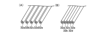
- the five lead wires 32a to 32e constituting the cable 30 are arranged in the order of lead wires 32a, 32b, 32c, 32d, and 32e from the +Y-axis direction side toward the -Y-axis direction side (from the top side of the drawing to the bottom side of the drawing). It is located.
- Each of the lead wires 32a-e has a core wire 34a-e and an insulating tube 36a-e.
- the core wires 34a to 34e are made of a conductor. Insulating tubes 36a-e cover each of core wires 34a-e.
- the insulating tubes 36a to 36e are made of polyimide resin or the like, similar to the insulating tube 16 covering the core wire 10. As shown in FIG. 3(C), the portions of the insulating tubes 36a to 36e disposed inside the connector assembly 40 are integrated by welding their outer peripheral surfaces to each other. That is, in the portion of the cable 30 disposed inside the connector assembly 40, the lead wires 32a to 32e are integrated except for a portion. Further, as shown in FIG. 3(C), in the portion of the cable 30 disposed inside the connector assembly 40, a portion of each of the insulating tubes 36a to 36e is peeled off on its entire circumference, and the core wire 34a to 34e are exposed. This exposed portion corresponds to a portion that is not integrated.
- FIG. 3(D) is an explanatory diagram illustrating a state in which the structure 40p includes the core wire 10 and the cable 30 inside.
- the state shown in FIG. 3(D) corresponds to the state shown in FIG. 2 with only the closing members 45a to 45e removed.
- the portions of the cable 30 where the insulating tubes 36a to 36e are peeled off and the core wires 34a to 34e are exposed are arranged inside the through holes 42a to 42e.
- the state shown in FIG. 2 is the state in which the through holes 42a to 42e are closed by the closing members 45a to 45e.
- FIG. 4 is a cross-sectional view showing each cross section of the proximal end portion of the guide wire 1 with a sensor.
- FIG. 4A shows a cross section taken along line F4A-F4A in FIG.
- the cross section in FIG. 4(A) is a cross section at a portion of the cable 30 where the core wire 34d is exposed.
- FIG. 4(B) shows a cross section taken along line F4B--F4B in FIG.
- the cross section of FIG. 4(B) is a cross section of a portion of the cable 30 where the core wire 34d is covered with the insulating tube 36d.
- FIG. 4(C) shows a vertical cross section taken along line F4C-F4C in FIGS. 4(A) and 4(B).
- the first region R1 shown in FIG. 4C is a region where the core wire 34d exposed in the X-axis direction is arranged inside the hollow electrode 41d. That is, the cross section of FIG. 4(A) is a cross section in the first region R1.
- a core wire 34d which is hidden by a conductive connecting member 47c to be described later and is not originally visible, is represented by a broken line.
- the insulating tube 36d of the lead wire 32d is peeled off and the core wire 34d is exposed, so the lead wire 32d arranged in the first region R1 is composed only of the core wire 34d. .
- FIG. 4(C) is a region different from the first region R1 inside the hollow electrode 41d, in which the core wire 34d covered with the insulating tube 36d is arranged in the X-axis direction. This is the area where That is, the cross section of FIG. 4(B) is a cross section in the second region R2.
- the third region R3 shown in FIG. 4(C) is a region on the side separated from the first region R1 from the second region R2 inside the hollow electrode 41d, and like the second region R2, in the X-axis direction. This is a region where a core wire 34d covered with an insulating tube 36d is arranged.
- a connecting member 47 is arranged inside the hollow electrode 41d.
- the connecting member 47 connects the core wire 10, the lead wires 32a to 32e, and the hollow electrode 41d.
- the connection member 47 includes a conductive connection member 47c and an insulating connection member 47i.
- the conductive connecting member 47c is an adhesive containing metal powder, and is disposed inside the hollow electrode 41d mainly around the exposed portion of the core wire 34d. Further, as shown in FIG.
- the conductive connecting member 47c covers at least a part of the lead wire 32d (consisting only of the core wire 34d in the first region R1), The lead wire 32d (core wire 34d) and the hollow electrode 41d are electrically connected.
- the conductive connection member 47c covers more than half the outer circumference of the cross section (YZ cross section) of the lead wire 32d (core wire 34d), and more specifically, covers the entire circumference.
- the insulating connecting member 47i is a non-conductive adhesive, and is placed inside the hollow electrode 41d so as to fill the part where the conductive connecting member 47c is not placed.
- the connecting member 47 arranged in this manner connects the core wire 10, the core wire 34d, and the hollow electrode 41d in the first region R1. Specifically, as explained in FIG. 3(B), since the core wire 10 disposed inside the connector assembly 40 is covered with the insulating tube 16, the connecting member 47 has a The core wire 10 and the hollow electrode 41d, and the core wire 10 and the core wire 34d are connected in an electrically insulated state. In addition, since the connecting member 47 is an adhesive and is filled in the first region R1, the connecting member 47 connects the core wire 10 and the hollow electrode 41d, and the core wire 10 and the core wire 34d to each other. are connected with their relative positions fixed.
- the lead wires 32c and 32e are spaced apart from the lead wire 32d.
- the lead wire 32d is composed of only the core wire 34d, and the lead wires 32c and 32e are spaced apart from the core wire 34d (lead wire 32d).
- the connecting member 47 connects the separated lead wire 32d (core wire 34d) and lead wires 32c and 32e, the core wire 10, and the hollow electrode 41d.
- the lead wires 32c and 32e are integrated with the lead wire 32d.
- the insulating tubes 36c to 36e have their outer circumferential surfaces fused together, so that the lead wire 32d and the lead wire 32c, It is integrated with 32e.
- the connecting member 47 connects the integrated lead wire 32d, lead wires 32c and 32e, the core wire 10, and the hollow electrode 41d.
- the connection state in the second region R2 described here is also the same in the third region R3.
- the lead wires 32c and 32e are integrated with the lead wire 32d, and the connecting member 47 connects the integrated lead wire 32d and the lead wires 32c and 32e, The core wire 10 and the hollow electrode 41d are connected.
- the core wire 34d is exposed and the lead wire 32d electrically connected to the hollow electrode 41d corresponds to a "main lead wire”. Further, in the first region R1 inside the hollow electrode 41d, it is spaced apart from the lead wire 32d (main lead wire), and in the second region R2 inside the hollow electrode 41d, the lead wire 32d (main lead wire) is separated from the lead wire 32d (main lead wire).
- the lead wires 32c and 32e that are integrated with the main wire correspond to "sub-lead wires.”
- the inside of the hollow electrodes 41a to 41c, e there are first to third regions similar to the inside of the hollow electrode 41d, and lead wires corresponding to the "main lead wire” and "auxiliary lead wire”. exist.
- the "main lead wire” in the hollow electrode 41a is the lead wire 32a
- the "sub-lead wire” is the lead wire 32b
- the “main lead wire” in the hollow electrode 41b is the lead wire 32b
- the "sub-lead wires" are the lead wires 32a and 32c.
- the “main lead wire” in the hollow electrode 41c is the lead wire 32c, and the “sub-lead wires” are the lead wires 32b and 32d.
- the “main lead wire” in the hollow electrode 41e is the lead wire 32e, and the “sub-lead wire” is the lead wire 32d.
- FIG. 5 is an enlarged cross-sectional view of sensor assembly 20.
- Sensor assembly 20 includes a tubular member 22, a sensor sheet 24, and spacers 26, 28.
- FIG. 6 is an explanatory diagram for explaining the details of the configuration of the tubular member 22 that is a part of the sensor assembly 20.
- the tubular member 22 includes a proximal tubular portion 22a, an intermediate connecting portion 22b, and a distal tubular portion 22c.
- the proximal cylindrical portion 22a is a cylindrical portion of the tubular member 22 on the proximal end side.
- a slit 22s that communicates the inside and outside of the base end cylindrical portion 22a is formed on the side surface of the base end cylindrical portion 22a.
- the intermediate connecting portion 22b is a portion of the tubular member 22 that connects the proximal end cylindrical portion 22a and the distal end cylindrical portion 22c, and its cross section (YZ cross section) exposes the inner surface of the intermediate connecting portion 22b to the outside. It is a semicircular part.
- the distal end cylindrical portion 22c is a cylindrical portion on the distal end side of the tubular member 22, and its cross section (YZ cross section) is approximately circular.
- FIG. 7 is an explanatory diagram for explaining the details of the configuration of the sensor sheet 24, which is a part of the sensor assembly 20.
- the sensor sheet 24 is a sheet-like member that is wound around the tubular member 22 .
- the sensor sheet 24 includes a widened portion 24a, a narrowed portion 24b, and sensor wiring 24c.
- the widened portion 24a is a band-shaped portion wider than the narrowed portion 24b.
- a sensor array 24s is arranged on the surface of the widened portion 24a.
- the sensor array 24s is composed of nine sensors arranged in a grid pattern. These sensors are sensors that measure the electrical resistance of body fluids such as blood flowing within blood vessels.
- the narrow portion 24b is a strip-shaped portion narrower in width than the widened portion 24a, and is connected to the widened portion 24a.
- Two microchips 24m connected to a sensor array 24s are arranged on the surface of the narrow portion 24b.
- the sensor wiring 24c is a wiring that transmits a signal sent from the microchip 24m, and is connected to the narrow portion 24b at a portion of the narrow portion 24b on the opposite side to the side connected to the widened portion 24a. ing.
- FIG. 8 is an explanatory diagram for explaining the process of winding the sensor sheet 24 around the tubular member 22.
- the state shown in FIG. 8 is achieved by arranging the sensor wiring 24c inside the tubular member 22 through a slit 22s (not shown in FIG. 8, see FIG. 6) formed in the proximal tubular portion 22a, thereby making an intermediate connection.
- the annular spacers 26 and 28 are attached to the tubular member 22.
- the annular spacers 26 and 28 are attached to the end portions of the base end cylindrical portion 22a and the distal end cylindrical portion 22c on the intermediate connecting portion 22b side.
- a portion of the sensor sheet 24 located inside the tubular member 22 is indicated by a broken line.
- the narrow portion 24b of the sensor sheet 24 is wound around the intermediate connecting portion 22b located between the spacers 26 and 28. It will be destroyed.
- the two microchips 24m arranged on the surface of the narrow width part 24b are wound around the intermediate connection part 22b so that one is stacked on the other (see FIG. 5).
- the widened part 24a is wound around the outer peripheral surfaces of the narrow part 24b and the spacers 26 and 28, which are wound around the intermediate connecting part 22b, so that the sensor sheet 24 is wound around the tubular member 22. ends.
- nine sensors forming the sensor array 24s are arranged on the outermost periphery of the tubular member 22. Further, in the cross section (YZ section) of the tubular member 22, three sensors are arranged at intervals of 120° along the circumferential direction.
- the tubular member 22 around which the sensor sheet 24 is provided is arranged to surround the core wire 10.
- the sensor assembly 20 further includes a distal joining member 25.
- the distal end joining member 25 joins the core wire 10 , the tubular member 22 , the sensor sheet 24 , the spacers 26 and 28 , and the first coil body 60 and the second coil body 70 .
- any bonding agent can be used for the distal bonding member 25.
- the outer diameter L1 of the base end portion of the first coil body 60 is larger than the outer diameter L2 of the tubular member 22 including the sensor sheet 24.
- the outer diameter L2 is the maximum outer diameter among the outer diameters of the tubular member 22 including the sensor sheet 24, and for example, the outer diameter at the position where the widened portion 24a is wound on the outer peripheral surface of the spacers 26 and 28 is the outer diameter.
- the outer diameter L1 is larger than the outer diameter L2.
- the base end cylindrical portion 22a) and the distal end portion of the second coil body 70 are joined.
- the outer diameter L3 of the tip of the second coil body 70 is larger than the outer diameter L2 of the tubular member 22 including the sensor sheet 24.
- the first section S1 is a section located at the tip of the core wire 10, and is a section where the sensor assembly 20 is arranged in the X-axis direction.
- the base end of the first section S1 is the position of the base end of the sensor wiring 24c (see FIG. 5).
- the second section S2 is a section located at the base end of the core wire 10, and is a section where the connector assembly 40 is arranged in the X-axis direction.
- the tip of the second section S2 is the tip of the inter-ring joining member 43a (see FIG. 2).
- the cable 30 is electrically connected to the sensor wiring 24c in the first section S1 (see FIG. 5), and is electrically connected to each of the hollow electrodes 41a to 41e in the second section S2.
- the electrical connection in the first section S1 is achieved by peeling off a portion of the outer peripheral surface of each of the insulating tubes 36a to 36e at the distal ends of the lead wires 32a to 32e constituting the cable 30, and forming the core wires 34a to 34a. This is a connection between the exposed portion e (not shown) and each of the five core wire connection portions (not shown) provided on the sensor wiring 24c.
- FIG. 9 is an explanatory diagram for explaining details of a portion of the cable 30 disposed between the first section S1 and the second section S2.
- an arbitrary position between the base end of the first section S1 and the tip of the second section S2 is defined as an intermediate position MP.
- the lead wires 32a to 32e in the said interval between the base end of the first section S1 and the intermediate position MP
- the entire structure is not integrated and is relatively movable.
- the lead wires 32a to 32e have the outer peripheral surfaces of the insulating tubes 36a to 36e fused to each other. Because they are separated without being tied together, they can move freely without following each other's movements.
- the length of the portion of the lead wires 32a to 32e located between the base end of the first section S1 and the intermediate position MP is the length of the part (between the base end of the first section S1 and the intermediate position MP). Since the lead wires 32a to 32e are longer than the length of the lead wires 32a to 32b, the lead wires 32a to 32e are arranged in a bent state between them.
- the entire lead wires 32a to 32e between the intermediate position MP and the tip of the second section S2 are as shown in the figure. As shown in 9(B), they are integrated. That is, in the portion of the cable 30 disposed between the intermediate position MP and the tip of the second section S2, the lead wires 32a to 32e have the outer peripheral surfaces of the insulating tubes 36a to 36e fused to each other. It is unified by this. In this way, between the proximal end of the first section S1 and the distal end of the second section S2, the cable 30 has the lead wires 32a to 32e integrated with the intermediate position MP as the boundary, as shown in FIG.
- the lead wires 32a to 32e are integrated, and a portion P2 where the lead wires 32a to 32e are integrated. Note that in the cable 30 electrically connected to the sensor wiring 24c from the base end to the distal end side of the first section S1, the lead wires 32a to 32e are integrated. Also, in the cable 30 from the distal end to the proximal end of the second section S2, the lead wires 32a to 32e are integrated except for a part, as explained in FIG. 3(C).
- the base end of the second coil body 70 of the sensor-equipped guide wire 1 corresponds to the intermediate position MP. Therefore, in the cable 30 disposed inside the second coil body 70, the lead wires 32a to 32e are not integrated and are relatively movable. Moreover, since the intermediate position MP is a position included in the intermediate joining member 75, the cable 30 is joined to the core wire 10 at the intermediate position MP. Note that between the sensor assembly 20 and the connector assembly 40, the cable 30 is joined to the core wire 10 at a position where the intermediate joining member 75 and the proximal joining member 85 are arranged, and At a position where the member 85 is not placed, it is not joined to the core wire 10. Further, between the sensor assembly 20 and the connector assembly 40, the cable 30 is not wound around the core wire 10 but extends along the core wire 10.
- the lead wires 32a to 32e have the same length between the base end of the first section S1 and the intermediate position MP. Note that “equal” here allows for manufacturing errors, etc., and even if the lengths of the lead wires 32a to 32e are different within a predetermined error range, they are equal. shall be.
- the lead wires 32a to 32e are not integrated between the proximal end of the first section S1 and the intermediate position MP, but are integrated between the intermediate position MP and the distal end of the second section S2. Therefore, if one of the lead wires 32a to 32e is designated as the "first lead wire,” any of the remaining four lead wires will be designated as the “second lead wire.” Corresponds to “line”. That is, the "first lead wire” is a lead wire that is not integrated with the "second lead wire” between the base end of the first section S1 and the intermediate position MP, and is a lead wire that is not integrated with the "second lead wire” between the base end of the first section S1 and the intermediate position MP. This lead wire is integrated with the "second lead wire” between the leading end of the second section S2.
- the lead wire 32d and the hollow electrode 41d are electrically connected. Therefore, when the hollow electrode 41d is connected to an external device that processes an output signal from the sensor array 24s, the sensor array 24s is connected to the hollow electrode 41d via the lead wire 32d connected to the sensor wiring 24c and The output signal can be transmitted to an external device. Further, according to the sensor-equipped guide wire 1 of the first embodiment, as shown in FIGS. 4(A) and 4(C), in the first region R1, the core wire 10 and the hollow electrode 41d, and the core wire 10 and the lead The wire 32d is connected in an insulated manner.
- the connecting member 47 covers the lead wire 32c and the lead wire 32d spaced apart from the lead wire 32e, and connects the lead wire 32d to the hollow electrode 41d. Not only is it connected, but it is also connected to the core wire 10. Therefore, it is possible to suppress changes in the relative position of the hollow electrode 41d with respect to the core wire 10. Therefore, it is possible to suppress the occurrence of damage to the lead wire 32d due to being sandwiched between the core wire 10 whose relative position has changed and the hollow electrode 41d. Further, in the first region R1, since the core wire 10 is insulated from the hollow electrode 41d and the lead wire 32d, it is also possible to suppress the output signal from the sensor array 24s from being transmitted to the core wire 10. The configuration and effects described here are also the same in the first regions inside the hollow electrodes 41a to 41c and e.
- the portions of the outer peripheral surface of the lead wire 32d and the outer peripheral surfaces of the lead wires 32c and 32e that are in contact with each other are exposed to the outside. Not exposed.
- the lead wire 32d is separated from the lead wires 32c and 32e, the entire outer circumferential surface of the lead wire 32d and the outer circumferential surfaces of the lead wires 32c and 32e are exposed to the outside.
- the sensor-equipped guide wire 1 of the first embodiment as shown in FIGS.
- the lead wire 32d is spaced apart from the lead wires 32c and 32e in the first region R1, and the lead wire 32d is spaced apart from the lead wires 32c and 32e in the second region R2.
- the lead wire 32d is integrated with the lead wires 32c and 32e. Therefore, in the lead wire 32d and the lead wires 32c and 32e separated in the first region R1, the outer circumferential surface of the lead wire 32d and the lead wire 32c, compared to the integrated lead wire 32d and the lead wires 32c and 32e, The connection area to which the connection member 47 can be connected can be increased on each of the outer circumferential surfaces of 32e.
- the connection strength between the lead wire 32d and the lead wires 32c and 32e, and the core wire 10 and the hollow electrode 41d can be increased.
- the second region R2 even if the connection between the lead wire 32d and the lead wires 32c and 32e and the core wire 10 and the hollow electrode 41d is severed due to peeling of the connecting member 47 or the like, the lead wire 32d and the Since the lead wires 32c and 32e are integrated, entanglement of the lead wire 32d and the lead wires 32c and 32e can be suppressed.
- the connecting member 47 connects the lead wire 32d to the core wire 10 and the hollow electrode 41d in a state where the lead wire 32d is integrated with the lead wires 32c and 32e. Therefore, it is possible to suppress the separation of the lead wire 32d from the lead wires 32c and 32e in the first region R1 from proceeding to the second region R2.
- the configuration and effects described here are the same in the first and second regions inside the hollow electrodes 41a to 41c and e.
- the lead wires 32c and 32e are integrated with the lead wire 32d even in the third region R3. Therefore, in the third region R3 as well as in the second region R2, when the connection between the lead wire 32d and the lead wires 32c and 32e and the core wire 10 and the hollow electrode 41d is broken, the lead wire 32d Also, it is possible to prevent the lead wires 32c and 32e from becoming entangled. Also in the third region R3, the connecting member 47 connects the lead wire 32d to the core wire 10 and the hollow electrode 41d in a state where the lead wire 32d is integrated with the lead wires 32c and 32e.
- the sensor-equipped guide wire 1 of the first embodiment as shown in FIG. It covers the circumference. Therefore, it is possible to make it difficult to separate the connecting member 47 from the lead wire 32d. Therefore, it is possible to prevent the connection between the lead wire 32d and the core wire 10 and the connection between the lead wire 32d and the hollow electrode 41d from being broken due to separation of the connecting member 47 from the lead wire 32d.
- the configuration and effects described here are also the same in the first regions inside the hollow electrodes 41a to 41c and e.
- the central axis of the tubular member 22 can be prevented from shifting from the central axis of the first coil body 60. Since the first coil body 60 constitutes the outer shape of the distal end of the guide wire 1 with a sensor, the central axis of the first coil body 60 corresponds to the central axis of the distal end of the guide wire 1 with a sensor. In other words, it is possible to prevent the center axis of the tubular member 22 from shifting from the center axis of the guide wire 1 with the sensor. Therefore, since the torque transmittance at the distal end of the sensor-equipped guide wire 1 is improved, the operability of the sensor-equipped guide wire 1 can be improved.
- the sensor-equipped guide wire 1 of the first embodiment as shown in FIG. big. Therefore, when the sensor-equipped guidewire 1 is inserted into a living body lumen such as a blood vessel, the sensor sheet 24 provided around the tubular member 22 or the tubular member 22 can be made difficult to come into contact with living tissue. . As a result, the possibility of damage to the sensor sheet 24 can be reduced, and the safety of the sensor-equipped guide wire 1 with respect to living tissue can be improved.
- the central axis of the tubular member 22 can be prevented from shifting from the central axis of the second coil body 70.
- the second coil body 70 constitutes a part of the outer shape of the guide wire 1 with a sensor
- the central axis of the second coil body 70 corresponds to a part of the central axis of the guide wire 1 with a sensor.
- the torque transmittance of the portion of the sensor-equipped guide wire 1 whose outer shape is constituted by the second coil body 70 is improved, the operability of the sensor-equipped guide wire 1 can be further improved.
- the sensor-equipped guide wire 1 of the first embodiment as shown in FIG. . Therefore, when the sensor-equipped guidewire 1 is inserted into a living body lumen such as a blood vessel, the sensor sheet 24 provided around the tubular member 22 or the tubular member 22 can be made difficult to come into contact with living tissue. . As a result, the possibility of damage to the sensor sheet 24 can be reduced, and the safety of the sensor-equipped guide wire 1 with respect to living tissue can be improved.
- the cable 30 (see FIG. 1) disposed between the proximal end of the first section S1 and the intermediate position MP is as shown in FIG. 9(A).
- the lead wires 32a to 32e are not integrated and are movable relative to each other. Therefore, between the proximal end of the first section S1 and the intermediate position MP, the lead wires 32a to 32e can move freely without following each other's movement, so the tip of the sensor-equipped guide wire 1 side flexibility can be ensured.
- the cable 30 (see FIG. 1) disposed between the intermediate position MP and the tip of the second section S2 has the following characteristics as shown in FIG.
- Lead wires 32a-e are integrated. Therefore, it is possible to prevent the lead wires 32a to 32e from becoming entangled between the intermediate position MP and the distal end of the second section S2, thereby ensuring operability of the sensor-equipped guide wire 1 on the proximal side of the intermediate position MP. can do. Therefore, according to the sensor-equipped guide wire 1 of the first embodiment, it is possible to achieve both flexibility on the distal end side and operability on the proximal end side, thereby providing a sensor-equipped guide wire 1 with improved ease of handling. Can be done.
- the lead wires 32a to 32e that are not integrated are caused by the lead wires 32a to 32a caught on the second coil body 70 pulling the core wire 10. It is possible to prevent the core wire 10 from becoming bent. This is because, for example, even if one of the unintegrated lead wires 32a to 32e gets caught in the second coil body 70, it is difficult to generate a pulling force that would cause the core wire 10 to bend. be. Further, by being arranged in a bent state, it is possible to suppress the occurrence of disconnection of the lead wires 32a to 32e that are not integrated due to rotational operation of the guide wire 1 with the sensor or insertion into a bent part. .
- the lead wires 32a to 32e are not integrated and are movable relative to each other. Therefore, since the flexible portion of the cable 30 where the lead wires 32a to 32e are not integrated is covered with the flexible second coil body 70, flexibility on the tip side is ensured.
- a sensor-equipped guide wire 1 can be provided.
- the cable 30 is joined to the core wire 10 at the intermediate position MP. Therefore, the integrated lead wires 32a to 32a to e on the proximal end side of the intermediate position MP are prevented from being pulled apart by the unintegrated lead wires 32a to 32e on the distal side of the intermediate position MP. be able to. That is, a portion where the lead wires 32a to 32e are not integrated and a portion where the lead wires 32a to 32e are integrated can be maintained with the intermediate position MP as a boundary.
- the lengths of the lead wires 32a to 32e are equal between the proximal end of the first section S1 and the intermediate position MP.
- the length of the lead wire 32d is longer than the length of the lead wire 32a.
- the length of ⁇ c and e plus the extra length corresponds to the length of ⁇ c and e plus the extra length. The longer the excess length is, the higher the possibility that the lead wire 32d will become entangled with the lead wires 32a to 32c, e and the core wire 10.
- the lead wires 32a to 32e are equal between the proximal end of the first section S1 and the intermediate position MP, the lead wires 32a to 32e The possibility of the wires getting tangled with each other or with the core wire 10 can be reduced.
- FIG. 10 is an explanatory diagram showing a schematic configuration of a sensor-equipped guide wire 1A according to the second embodiment.
- the sensor-equipped guide wire 1A of the second embodiment is different from the sensor-equipped guide wire 1 (FIG. 1) of the first embodiment in that it includes a sensor assembly 20a, an inner coil body 62, a first tip joining member 64, and a The difference is that a two-tip joining member 66 is provided.
- FIG. 11 is an enlarged view of the vicinity of the sensor assembly 20a.
- the sensor assembly 20a is the same as the sensor assembly 20 of the first embodiment, except that it includes a distal joint member 25a that is different from the distal joint member 25 of the first embodiment.
- the distal side joining member 25a joins the core wire 10, the tubular member 22, the sensor sheet 24, the spacers 26, 28, the first coil body 60, the second coil body 70, and the inner coil body 62. There is.
- the inner coil body 62 is disposed between the first coil body 60 and the core wire 10 and surrounds the tip of the core wire 10. Further, the base end portion of the inner coil body 62 is arranged inside the tip portion (the tip cylindrical portion 22c) of the tubular member 22.
- the first tip joining member 64 joins the first coil body 60 and the inner coil body 62.
- the second tip joining member 66 joins the base end of the inner coil body 62 and the core wire 10.
- Any bonding agent can be used for the first distal joining member 64 and the second distal joining member 66, similarly to the distal end joining member 25, the intermediate joining member 75, and the proximal joining member 85.
- a brazing material or adhesive made of silver, tin, copper, etc. may be used as the first end joining member 64 and the second end joining member 66.
- the sensor-equipped guide wire 1A of the second embodiment as described above can also provide the same effects as the first embodiment. Further, according to the sensor-equipped guide wire 1A of the second embodiment, the proximal end portion of the inner coil body 62 is disposed between the distal end portion (distal end cylindrical portion 22c) of the tubular member 22 and the core wire 10. Therefore, displacement of the relative position of the tubular member 22 with respect to the core wire 10 can be suppressed. That is, it is possible to suppress the central axis of the tubular member 22 from shifting from the central axis of the core wire 10. Therefore, the torque transmittance of the sensor-equipped guide wire 1A is improved, and the operability can be further improved.
- FIG. 12 is an explanatory diagram showing a schematic configuration of a sensor-equipped guide wire 1B according to the third embodiment.
- the sensor-equipped guide wire 1B of the third embodiment differs from the sensor-equipped guide wire 1A (FIG. 10) of the second embodiment in that the intermediate position MP is different from the intermediate joint member of the first and second embodiments.
- the difference is that a first intermediate joining member 77 and a second intermediate joining member 79 are provided instead of 75.
- the intermediate position MP corresponds to the boundary between the part where the lead wires 32a to 32e are not integrated and the part where the lead wires 32a to 32e are integrated.
- the intermediate position MP is the position of the base end of the second coil body 70, but in the sensor-equipped guide wire 1B of the third embodiment, the intermediate position MP is the position of the proximal end of the second coil body 70. MP is provided closer to the base end than the base end of the second coil body 70 .
- the first intermediate joining member 77 joins the second coil body 70 and the tube 80.
- the second intermediate joining member 79 is arranged to include the intermediate position MP, and joins the core wire 10, the cable 30, and the tube 80. That is, also in the sensor-equipped guide wire 1B of the third embodiment, the cable 30 is joined to the core wire 10 at the intermediate position MP.
- the sensor-equipped guide wire 1B of the third embodiment as described above can also provide the same effects as the first embodiment. Further, according to the sensor-equipped guide wire 1B of the third embodiment, it is possible to provide the sensor-equipped guide wire 1B in which flexibility is ensured from the base end of the second coil body 70 to the proximal end side.
- FIG. 13 is a sectional view showing a cross section of a sensor-equipped guide wire 1C according to the fourth embodiment.
- the cross section of FIG. 13 is a cross section of the sensor-equipped guide wire 1C of the fourth embodiment, which corresponds to the cross-section of the sensor-equipped guide wire 1 of the first embodiment shown in FIG. 4(C).
- the sensor-equipped guide wire 1C of the fourth embodiment is different from the sensor-equipped guide wire 1 of the first embodiment mainly in the first region inside the hollow electrodes 41a to 41e (core wire 34a exposed in the X-axis direction).
- the sensor-equipped guide wire 1 of the first embodiment is different from the sensor-equipped guide wire 1 of the first embodiment except that the arrangement of the regions (areas in which the electrodes 41a to 41e are arranged) is different and that the through holes 42a to 42e are not formed in the hollow electrodes 41a to 41e. is the same as
- the entire core wire 34d exposed in the X-axis direction is
- the sensor-equipped guide wire 1C of the fourth embodiment as shown in FIG. 13 a part of the core wire 34d exposed in the X-axis direction is arranged inside the hollow electrode 41d, The remaining portion is arranged inside the inter-ring joining member 43d.
- a portion of the core wire 34d exposed in the X-axis direction that is disposed inside the hollow electrode 41d corresponds to the first region R1. Due to the arrangement of the first region R1, in the sensor-equipped guide wire 1C of the fourth embodiment, the second region R2 exists, but the third region R3 does not exist.
- the conductive connecting member 47c is arranged around the core wire 34d exposed in the first region R1, as in the first embodiment. Further, the conductive connecting member 47c is also arranged around the core wire 34d arranged inside the inter-ring joining member 43d.
- the sensor-equipped guide wire 1C of the fourth embodiment as described above can also produce the same effects as the first embodiment. Further, according to the sensor-equipped guide wire 1C of the fourth embodiment, since the through-holes 42a-e are not formed in the hollow electrodes 41a-e, the sensor-equipped guide wire 1C includes the highly rigid connector assembly 40. can be provided.
- FIG. 14 is an explanatory diagram showing a schematic configuration of a sensor-equipped guide wire 1D according to the fifth embodiment.
- the sensor-equipped guide wire 1D of the fifth embodiment differs from the sensor-equipped guide wire 1 of the first embodiment (FIG. 1) in that it further includes a proximal tube 90 and a tube joining member 95.
- the length of the tube 80 in the X-axis direction is shorter than that of the sensor-equipped guide wire 1A (FIG. 1) of the first embodiment.
- a proximal tube 90 is disposed between the shortened tube 80 and the connector assembly 40.
- the proximal tube 90 like the tube 80, is a substantially cylindrical tube having a substantially constant outer diameter from the proximal end to the distal end.
- the proximal tube 90 is made of a material with higher strength than the tube 80.
- the tube joining member 95 joins the tube 80 and the proximal tube 90.
- the sensor-equipped guide wire 1D of the fifth embodiment as described above can also achieve the same effects as the first embodiment. Further, according to the sensor-equipped guide wire 1D of the fifth embodiment, the proximal tube 90, which has higher strength than the tube 80, is arranged on the proximal side, so that the operability on the proximal side is improved. A guidewire 1D with a sensor can be provided.
- a sensor-equipped guidewire may include a sensor that measures blood pressure (intravascular pressure). Blood pressure measured by such a sensor is used to derive fractional flow reserve (FFR).
- FFR fractional flow reserve
- the coronary flow reserve ratio is the pressure behind the stenosis relative to the pressure in front of the stenosis, and can be used as an index of physiological stenosis severity.
- connection member 47 is arranged (filled) inside the hollow electrode 41d without any gaps; however, the present invention is not limited to this. . That is, in the first region R1, the connecting member 47 electrically connects the lead wire 32d (core wire 34d) and the hollow electrode 41d, and also connects the core wire 10 and the hollow electrode 41d, as well as the core wire 10 and the hollow electrode 41d. As long as it is connected to the core wire 34d in an electrically insulated state, it may be arbitrarily placed inside the hollow electrode 41d.
- the connecting member 47 may be arranged with a gap, or the connecting member 47 is not connected between the first to third regions R1 to R3, and is independent in each region. It may be arranged as follows. Further, when the portion of the core wire 10 disposed inside the connector assembly 40 is covered with the insulating tube 16, the connecting member 47 is composed only of the conductive connecting member 47c without including the insulating connecting member 47i. It is also possible to do so. On the other hand, if the portion of the core wire 10 disposed inside the connector assembly 40 is not covered with the insulating tube 16, the periphery of the core wire 10 inside the hollow electrode 41d is covered with an insulating connecting member 47i.
- the connecting member 47 is arranged to cover the entire outer circumference of the cross section (YZ cross section) of the core wire 34d, but the present invention is not limited to this. They may be arbitrarily arranged as long as they are arranged so as to connect at least a part of the outer periphery of the (YZ cross section) and the hollow electrode 41d.
- each of the hollow electrodes 41a to 41e has one through hole. Not only a hole but two or more through holes may be formed.
- the number of parts where the insulating tubes 36a to 36e are peeled off and the core wires 34a to 34e are exposed is formed in the same number as the number of through holes, and each through hole is It may be placed inside the .
- the sensor sheet 24, which is a sheet-like member, is wound around the tubular member 22, but the sensor is not limited to this, and the sensor may not be a sheet-like member. It may be attached to the tubular member 22 in any manner as long as it is provided on the tubular member 22. For example, the sensor may be attached directly to the outer or inner circumferential surface of the tubular member 22, or may be attached indirectly via another member.
- the cable 30 and the sensor wiring 24c are connected on the outside of the tubular member 22 (on the proximal end side of the tubular member 22). , may be connected inside the tubular member 22.
- the second coil body 70 is arranged as a tubular member surrounding the core wire 10 and the cable 30 on the proximal side of the first coil body 60, but the present invention is not limited thereto.
- the tubular member surrounding the core wire 10 and cable 30 on the proximal side of the first coil body 60 may be a substantially cylindrical tube as long as it has flexibility, or a spiral slit may be formed on the outer peripheral surface. It may also be a tube formed into a tube.
- the lead in the cable 30 is arranged between the base end of the first section S1 and the intermediate position MP.
- the lead in the cable 30 is arranged between the base end of the first section S1 and the intermediate position MP.
- all of the wires 32a to 32e are not integrated, only a portion of the lead wires 32a to 32e between them need not be integrated.
- the lead wires 32a to 32e between the leads 32a to 32e only the portion between the position closer to the proximal end than the base end of the first section S1 to the intermediate position MP may not be integrated;
- the lead wires 32a to 32e may have portions that are not integrated.
- the lead wires 32a to 32e are not integrated between the base end of the first section S1 and the intermediate position MP (herein referred to as the distal end section), and are not integrated between the base end of the first section S1 and the intermediate position MP.
- the second section S2 and the distal end thereof (herein referred to as the proximal section) are integrated, the present invention is not limited thereto.
- the lead wires 32a to 32e are not integrated, and in the proximal section, a combination of the lead wires 32a to 32b among the lead wires 32a to 32e and a combination of the lead wires 32c to e are combined. Each combination may be integrated separately.
- the lead wires 32a to 32b are not integrated in the distal section but are integrated in the proximal section, and the lead wires 32c to e are connected between the distal section and the proximal section. In either case, they may be integrated. In other words, as long as the number of lead wires integrated in the distal section is reduced compared to the proximal section, the lead wires that are integrated with other lead wires in the proximal section but not in the distal section are Can be set arbitrarily.
- the lead wires can be integrated by bundling two or more lead wires with an expandable annular member, or by placing the lead wires inside a cylindrical member that can contain two or more lead wires. , may be realized.
- the cable 30 (portion P2 where the lead wires 32a to 32e are integrated) and the core wire 10 are not joined between the intermediate joining member 75 and the proximal joining member 85.
- the cable 30 (portion P2 where the lead wires 32a to 32e are integrated) and the core wire 10 may be joined with an adhesive or the like. .
- the cable 30 is not wound around the core wire 10 and extends along the core wire 10 between the sensor assembly 20 and the connector assembly 40, but the cable 30 is not limited thereto.
- a portion P2 of the cable 30 in which at least the lead wires 32a to 32e are integrated may be wound around the core wire 10.
- a proximal tube 90 may be arranged instead of the tube 80. That is, the core wire 10 and the cable 30 between the intermediate joining member 75 and the proximal joining member 85 may be surrounded by the proximal tube 90.
- the configurations of the sensor-equipped guide wires 1, 1A to D of the first to fifth embodiments and the configurations of the modifications 1 to 8 may be combined as appropriate.
- the intermediate position MP may be provided closer to the proximal end than the proximal end of the second coil body 70, as described in the third embodiment.
- the through holes 42a to 42e may not be formed in the hollow electrodes 41a to 41e, as described in the fourth embodiment, As described in the fifth embodiment, the proximal tube 90 and tube joining member 95 may be provided.
- Sensor array 25 25 , 25a...Tip side joining member 26...Spacer 30...Cable 32a-e...Lead wire 34a-e...Core wire 36a-e...Insulating tube 40...Connector assembly 40p...Structure 41a-e...Hollow electrode 42a-e... Through holes 43a to e... Ring-to-ring joining member 45a to e... Closing member 47... Connection member 47c... Conductive connection member 47i... Insulating connection member 50... Tip tip 60... First coil body 62... Inner coil body 64...
Abstract
This sensor-attached guide wire comprises a core wire, a first coil body that surrounds a distal end section of the core wire, a distal end tip that joins the distal end of the core wire and the distal end of the first coil body, and a tubular member provided with a sensor. The tubular member surrounds the core wire, a distal end section of the tubular member is disposed inside a proximal end section of the first coil body, and the distal end section of the tubular member and the proximal end section of the first coil body are joined.
Description
本発明は、センサ付きガイドワイヤに関する。
The present invention relates to a guidewire with a sensor.
血管等の生体管腔内に挿入されるカテーテル等を案内するガイドワイヤには、センサが先端部に取り付けられたセンサ付きガイドワイヤがある。例えば、特許文献1には、センサを含む筐体を先端部に備えたセンサ付きガイドワイヤが開示されている。また、特許文献2には、センサを保持するセンサホルダを先端部に備えたセンサ付きガイドワイヤが開示されている。
Guidewires that guide catheters and the like inserted into living body lumens such as blood vessels include guidewires with sensors that have sensors attached to their distal ends. For example, Patent Document 1 discloses a guidewire with a sensor, which has a housing including a sensor at its distal end. Further, Patent Document 2 discloses a guide wire with a sensor that includes a sensor holder at the distal end for holding a sensor.
特許文献1,2に開示された筐体やセンサホルダの中心軸がセンサ付きガイドワイヤの中心軸からずれた場合、先端部へのトルク伝達性を低下させることから、センサ付きガイドワイヤの操作性の低下につながる。しかし、特許文献1,2では、筐体やセンサホルダの中心軸と、センサ付きガイドワイヤの中心軸と、のずれについては何ら考慮されていないから、センサ付きガイドワイヤにおいて、先端部におけるトルク伝達性を向上させたセンサ付きガイドワイヤの開発が望まれていた。
If the center axis of the housing or sensor holder disclosed in Patent Documents 1 and 2 deviates from the center axis of the sensor-equipped guide wire, the torque transmittance to the distal end will be reduced, which will reduce the operability of the sensor-equipped guide wire. leading to a decrease in However, in Patent Documents 1 and 2, since no consideration is given to the misalignment between the central axis of the housing or sensor holder and the central axis of the guide wire with a sensor, torque transmission at the distal end of the guide wire with a sensor is not considered at all. The development of a sensor-equipped guide wire with improved performance has been desired.
本発明は、上述の課題の少なくとも一部を解決するためになされたものであり、センサ付きガイドワイヤの先端部におけるトルク伝達性を向上させる技術の提供を目的とする。
The present invention has been made to solve at least part of the above-mentioned problems, and aims to provide a technique for improving torque transmittance at the distal end of a guidewire with a sensor.
本発明は、上述の課題の少なくとも一部を解決するためになされたものであり、以下の形態として実現することが可能である。
The present invention has been made to solve at least part of the above-mentioned problems, and can be realized as the following forms.
(1)本発明の一形態によれば、センサ付きガイドワイヤが提供される。このセンサ付きガイドワイヤは、コアワイヤと、前記コアワイヤの先端部を囲む第1コイル体と、前記コアワイヤの先端と、前記第1コイル体の先端と、を接合する先端チップと、センサが設けられた管状部材と、を備え、前記管状部材は、前記コアワイヤを囲み、前記管状部材の先端部は、前記第1コイル体の基端部の内側に配置されており、前記管状部材の先端部と前記第1コイル体の基端部とは接合されている。
(1) According to one embodiment of the present invention, a guide wire with a sensor is provided. This guide wire with a sensor is provided with a core wire, a first coil body surrounding the tip of the core wire, a tip that joins the tip of the core wire and the tip of the first coil body, and a sensor. a tubular member, the tubular member surrounds the core wire, the distal end of the tubular member is disposed inside the proximal end of the first coil body, and the distal end of the tubular member and the It is joined to the base end of the first coil body.
この構成によれば、管状部材の先端部は、第1コイル体の基端部の内側に配置されており、管状部材の先端部と第1コイル体の基端部とは接合されている。このため、管状部材の中心軸が、第1コイル体の中心軸からずれるのを抑制することができる。第1コイル体は、センサ付きガイドワイヤの先端部の外形を構成しているため、第1コイル体の中心軸は、センサ付きガイドワイヤの先端部における中心軸に相当することから、換言すれば、管状部材の中心軸が、センサ付きガイドワイヤの中心軸からずれるのを抑制することができる。したがって、センサ付きガイドワイヤの先端部におけるトルク伝達性が向上することから、センサ付きガイドワイヤの操作性を向上することができる。
According to this configuration, the distal end of the tubular member is disposed inside the proximal end of the first coil body, and the distal end of the tubular member and the proximal end of the first coil body are joined. Therefore, the central axis of the tubular member can be prevented from shifting from the central axis of the first coil body. Since the first coil body constitutes the outer shape of the distal end of the guide wire with a sensor, the central axis of the first coil body corresponds to the central axis of the distal end of the guide wire with a sensor. , it is possible to suppress the center axis of the tubular member from shifting from the center axis of the guide wire with the sensor. Therefore, since the torque transmittance at the distal end of the sensor-equipped guide wire is improved, the operability of the sensor-equipped guide wire can be improved.
(2)上記形態のセンサ付きガイドワイヤにおいて、前記第1コイル体の基端部の外径は、前記センサを含む前記管状部材の外径よりも大きくてもよい。
この構成によれば、センサ付きガイドワイヤが血管等の生体管腔内に挿入された際に、管状部材に設けられたセンサもしくは管状部材を生体組織に接触しにくくすることができる。その結果、センサに損傷が生じる可能性を低減することができるとともに、センサ付きガイドワイヤの生体組織に対する安全性を向上することができる。 (2) In the sensor-equipped guide wire of the above embodiment, the outer diameter of the proximal end portion of the first coil body may be larger than the outer diameter of the tubular member including the sensor.
According to this configuration, when the sensor-equipped guide wire is inserted into a living body lumen such as a blood vessel, it is possible to make it difficult for the sensor provided in the tubular member or the tubular member to come into contact with living tissue. As a result, the possibility of damage to the sensor can be reduced, and the safety of the sensor-equipped guidewire with respect to living tissue can be improved.
(3)上記形態のセンサ付きガイドワイヤにおいて、さらに、前記第1コイル体と前記コアワイヤとの間に配置されて、前記コアワイヤの先端部を囲む内側コイル体を備え、前記内側コイル体の基端部は、前記管状部材の先端部の内側に配置されていてもよい。
この構成によれば、管状部材の先端部とコアワイヤとの間に内側コイル体の基端部が配置されていることから、コアワイヤに対する管状部材の相対的な位置がずれるのを抑制することができる。すなわち、管状部材の中心軸がコアワイヤの中心軸からずれるのを抑制することができる。したがって、センサ付きガイドワイヤの操作性を一層向上することができる。 (3) The sensor-equipped guide wire of the above embodiment further includes an inner coil body disposed between the first coil body and the core wire and surrounding a distal end portion of the core wire, the proximal end of the inner coil body being arranged between the first coil body and the core wire. The portion may be disposed inside the distal end portion of the tubular member.
According to this configuration, since the proximal end of the inner coil body is disposed between the distal end of the tubular member and the core wire, it is possible to suppress displacement of the relative position of the tubular member with respect to the core wire. . That is, it is possible to suppress the center axis of the tubular member from shifting from the center axis of the core wire. Therefore, the operability of the sensor-equipped guide wire can be further improved.
(4)上記形態のセンサ付きガイドワイヤにおいて、さらに、前記第1コイル体よりも基端側において前記コアワイヤを囲む第2コイル体を備え、前記管状部材の基端部は、前記第2コイル体の先端部の内側に配置されており、前記管状部材の基端部と前記第2コイル体の先端部とは接合されていてもよい。
この構成によれば、管状部材の中心軸が、第2コイル体の中心軸からずれるのを抑制することができる。第2コイル体は、センサ付きガイドワイヤの外形の一部を構成しているため、第2コイル体の中心軸は、センサ付きガイドワイヤの中心軸の一部に相当することから、換言すれば、管状部材の中心軸が、センサ付きガイドワイヤの中心軸からずれるのを抑制することができる。したがって、センサ付きガイドワイヤのうち外形が第2コイル体で構成された部分のトルク伝達性が向上することから、センサ付きガイドワイヤの操作性を一層向上することができる。 (4) The sensor-equipped guide wire of the above embodiment further includes a second coil body surrounding the core wire on the proximal side of the first coil body, and the proximal end of the tubular member is connected to the second coil body. The proximal end of the tubular member and the distal end of the second coil body may be joined to each other.
According to this configuration, it is possible to suppress the center axis of the tubular member from shifting from the center axis of the second coil body. Since the second coil body constitutes a part of the outer shape of the guide wire with a sensor, the central axis of the second coil body corresponds to a part of the central axis of the guide wire with a sensor. , it is possible to suppress the center axis of the tubular member from shifting from the center axis of the guide wire with the sensor. Therefore, since the torque transmittance of the portion of the sensor-equipped guidewire whose outer shape is formed by the second coil body is improved, the operability of the sensor-equipped guidewire can be further improved.
(5)上記形態のセンサ付きガイドワイヤにおいて、前記第2コイル体の先端部の外径は、前記センサを含む前記管状部材の外径よりも大きくてもよい。
この構成によれば、センサ付きガイドワイヤが血管等の生体管腔内に挿入された際に、管状部材に設けられたセンサもしくは管状部材を生体組織に接触しにくくすることができる。その結果、センサに損傷が生じる可能性を低減することができるとともに、センサ付きガイドワイヤの生体組織に対する安全性を向上することができる。 (5) In the sensor-equipped guide wire of the above embodiment, the outer diameter of the distal end portion of the second coil body may be larger than the outer diameter of the tubular member including the sensor.
According to this configuration, when the sensor-equipped guide wire is inserted into a living body lumen such as a blood vessel, it is possible to make it difficult for the sensor provided in the tubular member or the tubular member to come into contact with living tissue. As a result, the possibility of damage to the sensor can be reduced, and the safety of the sensor-equipped guidewire with respect to living tissue can be improved.
なお、本発明は、種々の態様で実現することが可能であり、例えば、センサ付きガイドワイヤを含む医療デバイス、センサ付きガイドワイヤを含むカテーテル、センサ付きガイドワイヤの製造方法などの形態で実現することができる。
Note that the present invention can be realized in various forms, such as a medical device including a guide wire with a sensor, a catheter including a guide wire with a sensor, a method for manufacturing a guide wire with a sensor, etc. be able to.
<第1実施形態>
図1は、第1実施形態のセンサ付きガイドワイヤ1の断面構成を例示した説明図である。なお、図1において、センサアセンブリ20及びコネクタアセンブリ40は、外観で示されている。本実施形態のセンサ付きガイドワイヤ1は、例えば、脳の血管に挿入して使用され、当該血管を流れる血液等の体液の電気抵抗を測定することが可能なデバイスである。センサ付きガイドワイヤ1によって検出された電気抵抗は、例えば、脳の血管に発生した血栓の種類の判定に用いられる。 <First embodiment>
FIG. 1 is an explanatory diagram illustrating a cross-sectional configuration of a sensor-equippedguidewire 1 according to the first embodiment. Note that in FIG. 1, the sensor assembly 20 and the connector assembly 40 are shown externally. The sensor-equipped guide wire 1 of this embodiment is a device that is used by being inserted into a cerebral blood vessel, for example, and is capable of measuring the electrical resistance of body fluids such as blood flowing through the blood vessel. The electrical resistance detected by the sensor-equipped guide wire 1 is used, for example, to determine the type of thrombus that has occurred in a cerebral blood vessel.
図1は、第1実施形態のセンサ付きガイドワイヤ1の断面構成を例示した説明図である。なお、図1において、センサアセンブリ20及びコネクタアセンブリ40は、外観で示されている。本実施形態のセンサ付きガイドワイヤ1は、例えば、脳の血管に挿入して使用され、当該血管を流れる血液等の体液の電気抵抗を測定することが可能なデバイスである。センサ付きガイドワイヤ1によって検出された電気抵抗は、例えば、脳の血管に発生した血栓の種類の判定に用いられる。 <First embodiment>
FIG. 1 is an explanatory diagram illustrating a cross-sectional configuration of a sensor-equipped
図1では、センサ付きガイドワイヤ1の中心を通る軸を軸線O(一点鎖線)で表す。以降、センサ付きガイドワイヤ1の各部材のうち少なくとも後述するコアワイヤ10、管状部材22(図5参照)、第1コイル体60及び第2コイル体70の中心を通る中心軸は、軸線Oに一致するものとして説明するが、その他の部材の中心を通る中心軸は、軸線Oからずれていてもよい。また、図1には、相互に直交するXYZ軸が図示されている。X軸はセンサ付きガイドワイヤ1の軸線方向(センサ付きガイドワイヤ1の挿入方向)に対応し、Y軸はセンサ付きガイドワイヤ1の幅方向に対応し、Z軸はセンサ付きガイドワイヤ1の高さ方向に対応する。図1の右側(+X軸方向)をセンサ付きガイドワイヤ1及び各構成部材の「先端側」と呼び、図1の左側(-X軸方向)をセンサ付きガイドワイヤ1及び各構成部材の「基端側」と呼ぶ。また、センサ付きガイドワイヤ1及び各構成部材について、先端側に位置する端部及びその近傍を「先端部」または単に「先端」と呼び、基端側に位置する端部及びその近傍を「基端部」または単に「基端」と呼ぶ。センサ付きガイドワイヤ1のうち、先端側は、生体内部へ挿入される部分であり、基端側は、医師等の術者により操作される部分である。これらの点は、図1以降においても共通する。
In FIG. 1, an axis passing through the center of the sensor-equipped guide wire 1 is represented by an axis O (dotted chain line). Hereinafter, the central axis passing through the center of at least the core wire 10, the tubular member 22 (see FIG. 5), the first coil body 60, and the second coil body 70, which will be described later, of each member of the sensor-equipped guide wire 1 coincides with the axis O. However, the central axes passing through the centers of other members may be offset from the axis O. Further, FIG. 1 shows XYZ axes that are orthogonal to each other. The X-axis corresponds to the axial direction of the sensor-equipped guide wire 1 (the insertion direction of the sensor-equipped guide wire 1), the Y-axis corresponds to the width direction of the sensor-equipped guide wire 1, and the Z-axis corresponds to the height of the sensor-equipped guide wire 1. Corresponds to the horizontal direction. The right side (+X-axis direction) of FIG. 1 is called the "distal side" of the guidewire 1 with sensor and each component, and the left side (-X-axis direction) of FIG. 1 is called the "base" of the guidewire 1 with sensor and each component. It is called the "end side". Regarding the sensor-equipped guide wire 1 and each component, the end located on the distal side and the vicinity thereof is referred to as the "distal end" or simply the "tip", and the end located on the proximal side and the vicinity thereof is referred to as the "base". ``end'' or simply ``proximal''. The distal end of the sensor-equipped guide wire 1 is the part that is inserted into the living body, and the proximal end is the part that is operated by an operator such as a doctor. These points are also common in FIG. 1 and subsequent figures.
センサ付きガイドワイヤ1は、コアワイヤ10と、センサアセンブリ20と、ケーブル30と、コネクタアセンブリ40とを備えている。コアワイヤ10は、X軸方向に沿って延びた長尺形状の部材である。コアワイヤ10は、先端側から基端側に向かって順に、先端細径部11、テーパ部12、太径部13、縮径部14、基端細径部15を有している。
The sensor-equipped guide wire 1 includes a core wire 10, a sensor assembly 20, a cable 30, and a connector assembly 40. The core wire 10 is a long member extending along the X-axis direction. The core wire 10 has, in order from the distal end to the proximal end, a distal end narrow diameter section 11, a taper section 12, a large diameter section 13, a reduced diameter section 14, and a proximal end narrow diameter section 15.
先端細径部11は、コアワイヤ10の最も先端側に設けられ、略一定の外径を有する略円柱形状であり、コアワイヤ10においての外径が最小の部分である。なお、本明細書において、「略一定」とは「概ね一定」と同義であり、製造誤差等に起因したぶれを許容しつつ、概ね一定であることを意味する。テーパ部12は、先端細径部11と太径部13との間に設けられ、基端側から先端側に向かって外径が徐々に縮小した部分である。太径部13は、テーパ部12と縮径部14との間に設けられ、先端細径部11や基端細径部15と比べて外径が大きい略円柱形状の部分である。縮径部14は、太径部13と基端細径部15との間に設けられ、先端側から基端側に向かって外径が徐々に縮小した部分である。基端細径部15は、縮径部14に基端側から隣接して設けられ、略一定の外径を有する略円柱形状であり、コアワイヤ10の外径が太径部13より小さい部分である。なお、先端細径部11、テーパ部12、太径部13、縮径部14、基端細径部15の外径、軸線O方向の長さ、及び横断面形状は、任意に決定できる。
The narrow end portion 11 is provided at the most distal end of the core wire 10, has a substantially cylindrical shape with a substantially constant outer diameter, and is the portion of the core wire 10 that has the smallest outer diameter. Note that in this specification, "substantially constant" has the same meaning as "approximately constant", and means being approximately constant while allowing for fluctuations due to manufacturing errors and the like. The tapered portion 12 is provided between the narrow end portion 11 and the large diameter portion 13, and is a portion whose outer diameter gradually decreases from the proximal end toward the distal end. The large-diameter portion 13 is provided between the tapered portion 12 and the reduced-diameter portion 14 and is a substantially cylindrical portion having a larger outer diameter than the narrow-diameter tip portion 11 and the narrow-diameter proximal portion 15 . The reduced diameter portion 14 is provided between the large diameter portion 13 and the proximal narrow diameter portion 15, and is a portion whose outer diameter gradually decreases from the distal end side to the proximal end side. The narrow proximal diameter portion 15 is provided adjacent to the reduced diameter portion 14 from the proximal end side, and has a substantially cylindrical shape with a substantially constant outer diameter, and is a portion of the core wire 10 where the outer diameter is smaller than the large diameter portion 13. be. Note that the outer diameters, lengths in the axis O direction, and cross-sectional shapes of the narrow end portion 11, the tapered portion 12, the large diameter portion 13, the reduced diameter portion 14, and the narrow base portion 15 can be arbitrarily determined.
センサアセンブリ20は、コアワイヤ10の先端部に配置されている。センサアセンブリ20は、血管内を流れる血液等の体液の電気抵抗を測定するセンサアレイ24s(図7参照)を含む構造体である。センサアセンブリ20の内側には、コアワイヤ10が挿通されている。センサアセンブリ20の詳細は、後述の図5~8にて説明する。
The sensor assembly 20 is placed at the tip of the core wire 10. The sensor assembly 20 is a structure that includes a sensor array 24s (see FIG. 7) that measures the electrical resistance of body fluids such as blood flowing in blood vessels. The core wire 10 is inserted inside the sensor assembly 20 . Details of the sensor assembly 20 will be explained later with reference to FIGS. 5 to 8.
ケーブル30は、コアワイヤ10に沿ってコアワイヤ10の基端部まで延びる5本のリード線32a~e(図3(C)や図9(A)(B)参照)を有し、センサアセンブリ20に含まれる後述のセンサ配線24c(図5参照)と、後述のコネクタアセンブリ40に含まれる中空状電極41a~e(図2参照)と、を電気的に接続している。ケーブル30の詳細は、後述の図3や図9にて説明する。なお、「電気的に接続」とは、電流を流せることが可能な状態(導通可能な状態)で接続されていることを意味する。
The cable 30 has five lead wires 32a to 32e (see FIGS. 3(C) and 9(A) and 9(B)) extending along the core wire 10 to the proximal end of the core wire 10, and connects to the sensor assembly 20. The included sensor wiring 24c (see FIG. 5), which will be described later, and hollow electrodes 41a to 41e (see FIG. 2) included in the connector assembly 40, which will be described later, are electrically connected. Details of the cable 30 will be explained later with reference to FIGS. 3 and 9. Note that "electrically connected" means connected in a state where current can flow (a state where conduction is possible).
コネクタアセンブリ40は、コアワイヤ10の基端部に配置されている。コネクタアセンブリ40は、後述のセンサアレイ24s(図7参照)からの出力信号を処理する外部デバイスと接続するための構造体である。コネクタアセンブリ40の内側には、コアワイヤ10のうち基端細径部15の一部と、ケーブル30と、が配置されている。コネクタアセンブリ40の詳細は、後述の図2~4にて説明する。
The connector assembly 40 is located at the proximal end of the core wire 10. The connector assembly 40 is a structure for connecting to an external device that processes an output signal from a sensor array 24s (see FIG. 7), which will be described later. Inside the connector assembly 40, a portion of the base narrow diameter portion 15 of the core wire 10 and the cable 30 are arranged. Details of the connector assembly 40 will be explained below with reference to FIGS. 2 to 4.
さらに、センサ付きガイドワイヤ1は、図1に示すように、先端チップ50と、第1コイル体60と、第2コイル体70と、中間接合部材75と、チューブ80と、基端側接合部材85とを備えている。
Further, as shown in FIG. 1, the sensor-equipped guide wire 1 includes a distal tip 50, a first coil body 60, a second coil body 70, an intermediate joining member 75, a tube 80, and a proximal joining member. 85.
先端チップ50は、コアワイヤ10の先端と、第1コイル体60の先端と、を接合する。先端チップ50は、任意の接合剤、例えば、銀ロウ、金ロウ、亜鉛、Sn-Ag合金、Au-Sn合金等の金属はんだや、エポキシ系接着剤などの接着剤によって形成できる。
The tip 50 joins the tip of the core wire 10 and the tip of the first coil body 60. The tip 50 can be formed using any bonding agent, for example, metal solder such as silver solder, gold solder, zinc, Sn--Ag alloy, Au--Sn alloy, or adhesive such as epoxy adhesive.
第1コイル体60及び第2コイル体70は、可撓性を有し、基端側から先端側に向かって略一定の外径を有する略円筒形状のコイル体である。第1コイル体60は、コアワイヤ10の先端部を囲むように配置されている。第2コイル体70は、第1コイル体60よりも基端側においてコアワイヤ10及びケーブル30を囲むように配置されている。具体的には、第2コイル体70は、センサアセンブリ20から基端側においてコアワイヤ10及びケーブル30を囲むように配置されている。第1コイル体60及び第2コイル体70は、センサアセンブリ20に接合されている。本実施形態では、第1コイル体60及び第2コイル体70は、1本の素線を単条に巻回して形成した単条コイルである。なお、第1コイル体60及び第2コイル体70は、複数本の素線を多条に巻回して形成した多条コイルであってもよく、複数本の素線を撚り合せた撚線を単条に巻回して形成した単条撚線コイルであってもよく、複数本の素線を撚り合せた撚線を複数用い、各撚線を多条に巻回して形成した多条撚線コイルであってもよい。第1コイル体60及び第2コイル体70の外径と内径とは、任意に決定できる。
The first coil body 60 and the second coil body 70 are flexible, substantially cylindrical coil bodies having a substantially constant outer diameter from the proximal end to the distal end. The first coil body 60 is arranged to surround the tip of the core wire 10. The second coil body 70 is arranged so as to surround the core wire 10 and the cable 30 on the proximal side of the first coil body 60 . Specifically, the second coil body 70 is arranged so as to surround the core wire 10 and the cable 30 on the proximal end side from the sensor assembly 20. The first coil body 60 and the second coil body 70 are joined to the sensor assembly 20. In this embodiment, the first coil body 60 and the second coil body 70 are single-filament coils formed by winding one strand into a single thread. Note that the first coil body 60 and the second coil body 70 may be multi-filament coils formed by winding a plurality of wires into multiple threads, or may be a stranded wire formed by twisting a plurality of wires together. It may be a single stranded wire coil formed by winding a single wire, or a multi-stranded wire formed by using a plurality of stranded wires made by twisting multiple strands together and winding each strand into multiple threads. It may also be a coil. The outer diameter and inner diameter of the first coil body 60 and the second coil body 70 can be arbitrarily determined.
チューブ80は、基端側から先端側に向かって略一定の外径を有する略円筒形状のチューブである。チューブ80は、第2コイル体70よりも基端側においてコアワイヤ10及びケーブル30を囲むように配置されている。チューブ80は、抗血栓性、可撓性、生体適合性を有することが好ましく、樹脂材料や金属材料で形成できる。樹脂材料としては、例えば、ポリイミド樹脂、ポリアミド樹脂、ポリオレフィン樹脂、ポリエステル樹脂、ポリウレタン樹脂、シリコン樹脂、フッ素樹脂等を採用できる。金属材料としては、例えば、SUS304等のステンレス鋼、ニッケルチタン合金、コバルトクロム合金等を採用できる。なお、チューブ80の外表面や、第1コイル体60及び第2コイル体70の外表面には、親水性又は疎水性の樹脂からなるコーティングが施されていてもよい。
The tube 80 is a substantially cylindrical tube having a substantially constant outer diameter from the proximal end to the distal end. The tube 80 is arranged so as to surround the core wire 10 and the cable 30 on the proximal side of the second coil body 70 . The tube 80 preferably has antithrombotic properties, flexibility, and biocompatibility, and can be formed from a resin material or a metal material. As the resin material, for example, polyimide resin, polyamide resin, polyolefin resin, polyester resin, polyurethane resin, silicone resin, fluororesin, etc. can be adopted. As the metal material, for example, stainless steel such as SUS304, nickel titanium alloy, cobalt chromium alloy, etc. can be used. Note that the outer surface of the tube 80 and the outer surfaces of the first coil body 60 and the second coil body 70 may be coated with a hydrophilic or hydrophobic resin.
中間接合部材75は、コアワイヤ10と、ケーブル30と、第2コイル体70と、チューブ80とを接合している。基端側接合部材85は、コアワイヤ10と、ケーブル30と、コネクタアセンブリ40と、チューブ80とを接合している。中間接合部材75及び基端側接合部材85には、先端チップ50と同様に、任意の接合剤を採用できる。なお、図1に示した第1区間S1、第2区間S2、中間位置MP、部分P1、部分P2については、後述する。
The intermediate joining member 75 joins the core wire 10, the cable 30, the second coil body 70, and the tube 80. The proximal joining member 85 joins the core wire 10, the cable 30, the connector assembly 40, and the tube 80. Similar to the distal tip 50, any bonding agent can be used for the intermediate bonding member 75 and the proximal bonding member 85. Note that the first section S1, second section S2, intermediate position MP, portion P1, and portion P2 shown in FIG. 1 will be described later.
次に、コネクタアセンブリ40の構成の詳細を説明する。図2は、コネクタアセンブリ40の拡大図である。センサ付きガイドワイヤ1の基端部に配置されたコネクタアセンブリ40は、図2に示すように、コアワイヤ10及びケーブル30を内側に含んでいる。コネクタアセンブリ40は、中空状電極41a~eと、リング間接合部材43a~eと、閉塞部材45a~eと、を備えている。
Next, details of the configuration of the connector assembly 40 will be explained. FIG. 2 is an enlarged view of connector assembly 40. FIG. The connector assembly 40 disposed at the proximal end of the sensor-equipped guidewire 1 includes the core wire 10 and the cable 30 therein, as shown in FIG. 2 . The connector assembly 40 includes hollow electrodes 41a-e, inter-ring joining members 43a-e, and closing members 45a-e.
図3は、コネクタアセンブリ40及びその内側に含まれたコアワイヤ10及びケーブル30の各々の詳細を説明するための説明図である。図3(A)は、コネクタアセンブリ40から閉塞部材45a~eを除いた構造体40pを示す。すなわち、構造体40pは、中空状電極41a~eと、リング間接合部材43a~eと、を備えている。中空状電極41a~eの各々は、コアワイヤ10の基端部に配置され、コアワイヤ10及びケーブル30を内側に含む(図2参照)。中空状電極41a~eは、先端側から基端側に向かって、中空状電極41a、41b、41c、41d、41eの順に配置されている。本実施形態では、中空状電極41a~eは、環状電極である。また、中空状電極41a~eの各々には、貫通孔42a~eが形成されている。コネクタアセンブリ40において、貫通孔42a~eの各々は、図2に示すように、閉塞部材45a~eによって閉塞されている。閉塞部材45a~eは、ポリイミド樹脂等の絶縁性部材である。
FIG. 3 is an explanatory diagram for explaining details of the connector assembly 40 and the core wire 10 and cable 30 included therein. FIG. 3A shows a structure 40p from the connector assembly 40 without the closure members 45a-e. That is, the structure 40p includes hollow electrodes 41a to 41e and inter-ring joining members 43a to 43e. Each of the hollow electrodes 41a to 41e is disposed at the base end of the core wire 10 and includes the core wire 10 and the cable 30 inside (see FIG. 2). The hollow electrodes 41a to 41e are arranged in this order from the distal end to the proximal end: hollow electrodes 41a, 41b, 41c, 41d, and 41e. In this embodiment, the hollow electrodes 41a to 41e are annular electrodes. Furthermore, through holes 42a to 42e are formed in each of the hollow electrodes 41a to 41e. In the connector assembly 40, each of the through holes 42a to 42e is closed by a closing member 45a to 45e, as shown in FIG. The closing members 45a to 45e are insulating members such as polyimide resin.
リング間接合部材43a~eは、ポリイミド樹脂等で形成された絶縁性の接合部材である。リング間接合部材43aは、中空状電極41aに先端側から隣接して配置され、中空状電極41aと、チューブ80と、を接合している(図1参照)。リング間接合部材43b~eの各々は、中空状電極41a~eの各々の間に配置され、中空状電極41a~eの各々を接合している。樹脂で形成されたリング間接合部材43a~eは比較的柔軟であることから、コネクタアセンブリ40において剛性が低い部分にあたる。このため、コネクタアセンブリ40が曲げられた際の負荷は、主に、リング間接合部材43a~eにかかりやすく、剛性が高い中空状電極41a~eにはかかりにくい。
The inter-ring joining members 43a to 43e are insulating joining members made of polyimide resin or the like. The inter-ring joining member 43a is arranged adjacent to the hollow electrode 41a from the tip side, and joins the hollow electrode 41a and the tube 80 (see FIG. 1). Each of the inter-ring joining members 43b to 43e is disposed between each of the hollow electrodes 41a to 41e, and joins each of the hollow electrodes 41a to 41e. Since the inter-ring joining members 43a to 43e made of resin are relatively flexible, they correspond to parts of the connector assembly 40 that have low rigidity. Therefore, when the connector assembly 40 is bent, the load tends to be applied mainly to the inter-ring joining members 43a to 43e, and is less likely to be applied to the hollow electrodes 41a to 41e, which have high rigidity.
図3(B)は、コアワイヤ10のうちコネクタアセンブリ40の内側に配置された部分を示す。図3(B)に示すように、コアワイヤ10のうちコネクタアセンブリ40の内側に配置された部分は、ポリイミド樹脂等で形成された絶縁性チューブ16に覆われている。
FIG. 3(B) shows a portion of the core wire 10 disposed inside the connector assembly 40. As shown in FIG. 3(B), the portion of the core wire 10 disposed inside the connector assembly 40 is covered with an insulating tube 16 made of polyimide resin or the like.
図3(C)は、ケーブル30のうちコネクタアセンブリ40の内側に配置されている部分を示す。ケーブル30を構成する5本のリード線32a~eは、+Y軸方向側から-Y軸方向側(図面上側から図面下側)に向かって、リード線32a、32b、32c、32d、32eの順に配置されている。リード線32a~eの各々は、芯線34a~eと、絶縁性チューブ36a~eと、を有する。芯線34a~eは、導体で形成されている。絶縁性チューブ36a~eは、芯線34a~eの各々を覆っている。絶縁性チューブ36a~eは、コアワイヤ10を覆う絶縁性チューブ16と同様に、ポリイミド樹脂等で形成されている。図3(C)に示すように、絶縁性チューブ36a~eのうちコネクタアセンブリ40の内側に配置されている部分は、互いの外周面が融着されることによって一体化されている。すなわち、ケーブル30のうちコネクタアセンブリ40の内側に配置されている部分では、一部を除いてリード線32a~eが一体化されている。また、図3(C)に示すように、ケーブル30のうちコネクタアセンブリ40の内側に配置されている部分において、絶縁性チューブ36a~eの各々の一部は全周が剥離されており、芯線34a~eが露出している。この露出部分が一体化されていない一部に相当する。
FIG. 3(C) shows a portion of the cable 30 that is disposed inside the connector assembly 40. The five lead wires 32a to 32e constituting the cable 30 are arranged in the order of lead wires 32a, 32b, 32c, 32d, and 32e from the +Y-axis direction side toward the -Y-axis direction side (from the top side of the drawing to the bottom side of the drawing). It is located. Each of the lead wires 32a-e has a core wire 34a-e and an insulating tube 36a-e. The core wires 34a to 34e are made of a conductor. Insulating tubes 36a-e cover each of core wires 34a-e. The insulating tubes 36a to 36e are made of polyimide resin or the like, similar to the insulating tube 16 covering the core wire 10. As shown in FIG. 3(C), the portions of the insulating tubes 36a to 36e disposed inside the connector assembly 40 are integrated by welding their outer peripheral surfaces to each other. That is, in the portion of the cable 30 disposed inside the connector assembly 40, the lead wires 32a to 32e are integrated except for a portion. Further, as shown in FIG. 3(C), in the portion of the cable 30 disposed inside the connector assembly 40, a portion of each of the insulating tubes 36a to 36e is peeled off on its entire circumference, and the core wire 34a to 34e are exposed. This exposed portion corresponds to a portion that is not integrated.
図3(D)は、構造体40pがコアワイヤ10及びケーブル30を内側に含んでいる状態を例示した説明図である。図3(D)に示す状態は、図2に示す状態から閉塞部材45a~eのみを除いた状態に相当する。図3(D)に示すように、ケーブル30のうち絶縁性チューブ36a~eが剥離されて芯線34a~eが露出している部分は、貫通孔42a~eの内側に配置されている。この貫通孔42a~eが閉塞部材45a~eで閉塞された状態が、図2で示した状態である。
FIG. 3(D) is an explanatory diagram illustrating a state in which the structure 40p includes the core wire 10 and the cable 30 inside. The state shown in FIG. 3(D) corresponds to the state shown in FIG. 2 with only the closing members 45a to 45e removed. As shown in FIG. 3(D), the portions of the cable 30 where the insulating tubes 36a to 36e are peeled off and the core wires 34a to 34e are exposed are arranged inside the through holes 42a to 42e. The state shown in FIG. 2 is the state in which the through holes 42a to 42e are closed by the closing members 45a to 45e.
図4は、センサ付きガイドワイヤ1の基端部の各断面を示した断面図である。図4(A)は、図2のF4A―F4A線における横断面を示している。図4(A)の横断面は、ケーブル30において芯線34dが露出している部分における断面である。図4(B)は、図2のF4B―F4B線における横断面を示している。図4(B)の横断面は、ケーブル30において芯線34dが絶縁性チューブ36dに覆われている部分における断面である。図4(C)は、図4(A)(B)のF4C―F4C線における縦断面を示している。図4(C)に示す第1領域R1は、中空状電極41dの内側のうちX軸方向において露出した芯線34dが配置されている領域である。すなわち、図4(A)の断面は、第1領域R1における断面である。なお、図4(C)に示す縦断面において、後述する導電性接続部材47cに隠れて本来見えない芯線34dは、破線で表している。第1領域R1では、リード線32dのうち絶縁性チューブ36dが剥離されて芯線34dが露出していることから、第1領域R1に配置されたリード線32dは、芯線34dのみから構成されている。図4(C)に示す第2領域R2は、中空状電極41dの内側のうち第1領域R1とは異なる領域であり、X軸方向において絶縁性チューブ36dに覆われた芯線34dが配置されている領域である。すなわち、図4(B)の断面は、第2領域R2における断面である。図4(C)に示す第3領域R3は、中空状電極41dの内側の第2領域R2から第1領域R1を隔てた側の領域であり、第2領域R2と同様に、X軸方向において絶縁性チューブ36dに覆われた芯線34dが配置されている領域である。
FIG. 4 is a cross-sectional view showing each cross section of the proximal end portion of the guide wire 1 with a sensor. FIG. 4A shows a cross section taken along line F4A-F4A in FIG. The cross section in FIG. 4(A) is a cross section at a portion of the cable 30 where the core wire 34d is exposed. FIG. 4(B) shows a cross section taken along line F4B--F4B in FIG. The cross section of FIG. 4(B) is a cross section of a portion of the cable 30 where the core wire 34d is covered with the insulating tube 36d. FIG. 4(C) shows a vertical cross section taken along line F4C-F4C in FIGS. 4(A) and 4(B). The first region R1 shown in FIG. 4C is a region where the core wire 34d exposed in the X-axis direction is arranged inside the hollow electrode 41d. That is, the cross section of FIG. 4(A) is a cross section in the first region R1. In addition, in the longitudinal section shown in FIG. 4(C), a core wire 34d, which is hidden by a conductive connecting member 47c to be described later and is not originally visible, is represented by a broken line. In the first region R1, the insulating tube 36d of the lead wire 32d is peeled off and the core wire 34d is exposed, so the lead wire 32d arranged in the first region R1 is composed only of the core wire 34d. . The second region R2 shown in FIG. 4(C) is a region different from the first region R1 inside the hollow electrode 41d, in which the core wire 34d covered with the insulating tube 36d is arranged in the X-axis direction. This is the area where That is, the cross section of FIG. 4(B) is a cross section in the second region R2. The third region R3 shown in FIG. 4(C) is a region on the side separated from the first region R1 from the second region R2 inside the hollow electrode 41d, and like the second region R2, in the X-axis direction. This is a region where a core wire 34d covered with an insulating tube 36d is arranged.
図4(A)~(C)に示すように、中空状電極41dの内側には、接続部材47が配置されている。接続部材47は、コアワイヤ10と、リード線32a~eと、中空状電極41dと、を接続している。接続部材47には、導電性接続部材47cと、絶縁性接続部材47iと、が含まれる。導電性接続部材47cは、金属粉が含まれた接着剤であり、中空状電極41dの内側において、主に、芯線34dが露出している部分の周辺に配置されている。また、図4(A)に示すように、第1領域R1において、導電性接続部材47cは、リード線32d(第1領域R1では芯線34dのみから構成)の少なくとも一部を被覆しており、リード線32d(芯線34d)と中空状電極41dとを電気的に接続している。本実施形態では、導電性接続部材47cは、リード線32d(芯線34d)の横断面(YZ断面)の外周のうち半周以上を被覆しており、より詳細には、全周を被覆している。絶縁性接続部材47iは、非導電性の接着剤であり、中空状電極41dの内側において、導電性接続部材47cが配置されていない部分を埋めるように配置されている。このように配置された接続部材47は、第1領域R1において、コアワイヤ10と、芯線34dと、中空状電極41dと、を接続している。詳細には、図3(B)で説明したように、コネクタアセンブリ40の内側に配置されたコアワイヤ10は絶縁性チューブ16で覆われていることから、接続部材47は、第1領域R1において、コアワイヤ10と中空状電極41dと、及び、コアワイヤ10と芯線34dと、を電気的に絶縁した状態で接続している。また、接続部材47は接着剤であるとともに第1領域R1内に充填されていることから、接続部材47は、コアワイヤ10と中空状電極41dと、及び、コアワイヤ10と芯線34dと、を、互いの相対位置が固定された状態で接続している。
As shown in FIGS. 4(A) to 4(C), a connecting member 47 is arranged inside the hollow electrode 41d. The connecting member 47 connects the core wire 10, the lead wires 32a to 32e, and the hollow electrode 41d. The connection member 47 includes a conductive connection member 47c and an insulating connection member 47i. The conductive connecting member 47c is an adhesive containing metal powder, and is disposed inside the hollow electrode 41d mainly around the exposed portion of the core wire 34d. Further, as shown in FIG. 4(A), in the first region R1, the conductive connecting member 47c covers at least a part of the lead wire 32d (consisting only of the core wire 34d in the first region R1), The lead wire 32d (core wire 34d) and the hollow electrode 41d are electrically connected. In this embodiment, the conductive connection member 47c covers more than half the outer circumference of the cross section (YZ cross section) of the lead wire 32d (core wire 34d), and more specifically, covers the entire circumference. . The insulating connecting member 47i is a non-conductive adhesive, and is placed inside the hollow electrode 41d so as to fill the part where the conductive connecting member 47c is not placed. The connecting member 47 arranged in this manner connects the core wire 10, the core wire 34d, and the hollow electrode 41d in the first region R1. Specifically, as explained in FIG. 3(B), since the core wire 10 disposed inside the connector assembly 40 is covered with the insulating tube 16, the connecting member 47 has a The core wire 10 and the hollow electrode 41d, and the core wire 10 and the core wire 34d are connected in an electrically insulated state. In addition, since the connecting member 47 is an adhesive and is filled in the first region R1, the connecting member 47 connects the core wire 10 and the hollow electrode 41d, and the core wire 10 and the core wire 34d to each other. are connected with their relative positions fixed.
図4(A)に示すように、第1領域R1において、リード線32c、32eは、リード線32dから離間されている。詳細には、第1領域R1では、上述したように、リード線32dは芯線34dのみから構成されており、その芯線34d(リード線32d)からリード線32c、32eは離間している。そして、第1領域R1において、接続部材47は、離間したリード線32d(芯線34d)及びリード線32c、32eと、コアワイヤ10と、中空状電極41dと、を接続している。一方、図4(B)に示すように、第2領域R2において、リード線32c、32eは、リード線32dと一体化されている。詳細には、第2領域R2において、絶縁性チューブ36c~eは、図3(C)で説明したように、互いの外周面が融着されていることから、リード線32dとリード線32c、32eとは一体化している。そして、第2領域R2において、接続部材47は、一体化されたリード線32d及びリード線32c、32eと、コアワイヤ10と、中空状電極41dと、を接続している。ここで説明した第2領域R2における接続状態は、第3領域R3においても同様である。具体的には、第3領域R3においても、リード線32c、32eは、リード線32dと一体化されており、接続部材47は、その一体化されたリード線32d及びリード線32c、32eと、コアワイヤ10と、中空状電極41dと、を接続している。
As shown in FIG. 4(A), in the first region R1, the lead wires 32c and 32e are spaced apart from the lead wire 32d. Specifically, in the first region R1, as described above, the lead wire 32d is composed of only the core wire 34d, and the lead wires 32c and 32e are spaced apart from the core wire 34d (lead wire 32d). In the first region R1, the connecting member 47 connects the separated lead wire 32d (core wire 34d) and lead wires 32c and 32e, the core wire 10, and the hollow electrode 41d. On the other hand, as shown in FIG. 4(B), in the second region R2, the lead wires 32c and 32e are integrated with the lead wire 32d. Specifically, in the second region R2, the insulating tubes 36c to 36e have their outer circumferential surfaces fused together, so that the lead wire 32d and the lead wire 32c, It is integrated with 32e. In the second region R2, the connecting member 47 connects the integrated lead wire 32d, lead wires 32c and 32e, the core wire 10, and the hollow electrode 41d. The connection state in the second region R2 described here is also the same in the third region R3. Specifically, in the third region R3 as well, the lead wires 32c and 32e are integrated with the lead wire 32d, and the connecting member 47 connects the integrated lead wire 32d and the lead wires 32c and 32e, The core wire 10 and the hollow electrode 41d are connected.
中空状電極41dの内側の第1領域R1において、芯線34dが露出し、且つ、中空状電極41dと電気的に接続するリード線32dは、「主リード線」に相当する。また、中空状電極41dの内側の第1領域R1において、リード線32d(主リード線)から離間されており、且つ、中空状電極41dの内側の第2領域R2において、リード線32d(主リード線)と一体化されているリード線32c、32eは、「副リード線」に相当する。また、中空状電極41a~c、eの内側においても、中空状電極41dの内側と同様の第1~3領域と、「主リード線」及び「副リード線」に相当するリード線と、が存在する。具体的には、中空状電極41aにおける「主リード線」は、リード線32aであり、「副リード線」は、リード線32bである。中空状電極41bにおける「主リード線」は、リード線32bであり、「副リード線」は、リード線32a、cである。中空状電極41cにおける「主リード線」は、リード線32cであり、「副リード線」は、リード線32b、dである。中空状電極41eにおける「主リード線」は、リード線32eであり、「副リード線」は、リード線32dである。
In the first region R1 inside the hollow electrode 41d, the core wire 34d is exposed and the lead wire 32d electrically connected to the hollow electrode 41d corresponds to a "main lead wire". Further, in the first region R1 inside the hollow electrode 41d, it is spaced apart from the lead wire 32d (main lead wire), and in the second region R2 inside the hollow electrode 41d, the lead wire 32d (main lead wire) is separated from the lead wire 32d (main lead wire). The lead wires 32c and 32e that are integrated with the main wire correspond to "sub-lead wires." Also, on the inside of the hollow electrodes 41a to 41c, e, there are first to third regions similar to the inside of the hollow electrode 41d, and lead wires corresponding to the "main lead wire" and "auxiliary lead wire". exist. Specifically, the "main lead wire" in the hollow electrode 41a is the lead wire 32a, and the "sub-lead wire" is the lead wire 32b. The "main lead wire" in the hollow electrode 41b is the lead wire 32b, and the "sub-lead wires" are the lead wires 32a and 32c. The "main lead wire" in the hollow electrode 41c is the lead wire 32c, and the "sub-lead wires" are the lead wires 32b and 32d. The "main lead wire" in the hollow electrode 41e is the lead wire 32e, and the "sub-lead wire" is the lead wire 32d.
次に、センサアセンブリ20の構成の詳細を説明する。図5は、センサアセンブリ20の拡大断面図である。センサアセンブリ20は、管状部材22と、センサシート24と、スペーサ26、28と、を備えている。
Next, details of the configuration of the sensor assembly 20 will be explained. FIG. 5 is an enlarged cross-sectional view of sensor assembly 20. FIG. Sensor assembly 20 includes a tubular member 22, a sensor sheet 24, and spacers 26, 28.
図6は、センサアセンブリ20の一部である管状部材22の構成の詳細を説明するための説明図である。管状部材22は、基端筒状部22aと、中間接続部22bと、先端筒状部22cと、から構成されている。基端筒状部22aは、管状部材22のうち基端側の筒状部分である。基端筒状部22aの側面には、基端筒状部22aの内外を連通するスリット22sが形成されている。中間接続部22bは、管状部材22のうち基端筒状部22aと先端筒状部22cとを接続する部分であり、その横断面(YZ断面)は、中間接続部22bの内面を外側に露出する半円形状の部分である。先端筒状部22cは、管状部材22のうち先端側の筒状部分であり、その横断面(YZ断面)は略円形状である。
FIG. 6 is an explanatory diagram for explaining the details of the configuration of the tubular member 22 that is a part of the sensor assembly 20. The tubular member 22 includes a proximal tubular portion 22a, an intermediate connecting portion 22b, and a distal tubular portion 22c. The proximal cylindrical portion 22a is a cylindrical portion of the tubular member 22 on the proximal end side. A slit 22s that communicates the inside and outside of the base end cylindrical portion 22a is formed on the side surface of the base end cylindrical portion 22a. The intermediate connecting portion 22b is a portion of the tubular member 22 that connects the proximal end cylindrical portion 22a and the distal end cylindrical portion 22c, and its cross section (YZ cross section) exposes the inner surface of the intermediate connecting portion 22b to the outside. It is a semicircular part. The distal end cylindrical portion 22c is a cylindrical portion on the distal end side of the tubular member 22, and its cross section (YZ cross section) is approximately circular.
図7は、センサアセンブリ20の一部であるセンサシート24の構成の詳細を説明するための説明図である。センサシート24は、管状部材22に巻回されるシート状の部材である。センサシート24は、拡幅部24aと、狭幅部24bと、センサ配線24cと、から構成されている。拡幅部24aは、狭幅部24bより幅の広い帯状部分である。拡幅部24aの表面には、センサアレイ24sが配置されている。センサアレイ24sは、格子状に配置された9つのセンサから構成されている。これらセンサは、血管内を流れる血液等の体液の電気抵抗を測定するセンサである。狭幅部24bは、拡幅部24aより幅の狭い帯状部分であり、拡幅部24aと接続している。狭幅部24bの表面には、センサアレイ24sと接続された2つのマイクロチップ24mが配置されている。センサ配線24cは、マイクロチップ24mから送られてくる信号を伝送する配線であり、狭幅部24bのうち拡幅部24aと接続している側とは反対側の部分で狭幅部24bと接続している。
FIG. 7 is an explanatory diagram for explaining the details of the configuration of the sensor sheet 24, which is a part of the sensor assembly 20. The sensor sheet 24 is a sheet-like member that is wound around the tubular member 22 . The sensor sheet 24 includes a widened portion 24a, a narrowed portion 24b, and sensor wiring 24c. The widened portion 24a is a band-shaped portion wider than the narrowed portion 24b. A sensor array 24s is arranged on the surface of the widened portion 24a. The sensor array 24s is composed of nine sensors arranged in a grid pattern. These sensors are sensors that measure the electrical resistance of body fluids such as blood flowing within blood vessels. The narrow portion 24b is a strip-shaped portion narrower in width than the widened portion 24a, and is connected to the widened portion 24a. Two microchips 24m connected to a sensor array 24s are arranged on the surface of the narrow portion 24b. The sensor wiring 24c is a wiring that transmits a signal sent from the microchip 24m, and is connected to the narrow portion 24b at a portion of the narrow portion 24b on the opposite side to the side connected to the widened portion 24a. ing.
図8は、管状部材22に対するセンサシート24の巻回過程を説明するための説明図である。図8に示す状態は、基端筒状部22aに形成されたスリット22s(図8に不図示、図6参照)を介してセンサ配線24cを管状部材22の内側に配置することにより、中間接続部22bから狭幅部24bを管状部材22の外側に突出させたのち、環状のスペーサ26、28を管状部材22に装着した状態である。環状のスペーサ26、28は、詳細には、基端筒状部22a及び先端筒状部22cのうち中間接続部22b側の端部に装着されている。図8において、センサシート24のうち管状部材22の内側に配置された部分は、破線にて示されている。このような状態から、センサシート24を管状部材22に巻いていくと、まず初めに、センサシート24のうち狭幅部24bがスペーサ26、28の間に位置した中間接続部22bの周囲に巻かれる。このとき、狭幅部24bの表面に配置された2つのマイクロチップ24mは、一方が他方に積み重ねられるように、中間接続部22bの周囲に巻かれる(図5参照)。その後、中間接続部22bの周囲に巻かれた狭幅部24bと、スペーサ26、28と、の外周面上に、拡幅部24aが巻かれることにより、管状部材22に対するセンサシート24の巻回過程が終了する。センサシート24の巻回後は、センサアレイ24sを構成する9つのセンサが管状部材22の最外周に配置されることとなる。また、管状部材22の横断面(YZ断面)においては、3つのセンサが、周方向に沿って120°間隔で配置されることとなる。
FIG. 8 is an explanatory diagram for explaining the process of winding the sensor sheet 24 around the tubular member 22. The state shown in FIG. 8 is achieved by arranging the sensor wiring 24c inside the tubular member 22 through a slit 22s (not shown in FIG. 8, see FIG. 6) formed in the proximal tubular portion 22a, thereby making an intermediate connection. After the narrow portion 24b is projected from the portion 22b to the outside of the tubular member 22, the annular spacers 26 and 28 are attached to the tubular member 22. Specifically, the annular spacers 26 and 28 are attached to the end portions of the base end cylindrical portion 22a and the distal end cylindrical portion 22c on the intermediate connecting portion 22b side. In FIG. 8, a portion of the sensor sheet 24 located inside the tubular member 22 is indicated by a broken line. When the sensor sheet 24 is wound around the tubular member 22 from this state, first, the narrow portion 24b of the sensor sheet 24 is wound around the intermediate connecting portion 22b located between the spacers 26 and 28. It will be destroyed. At this time, the two microchips 24m arranged on the surface of the narrow width part 24b are wound around the intermediate connection part 22b so that one is stacked on the other (see FIG. 5). Thereafter, the widened part 24a is wound around the outer peripheral surfaces of the narrow part 24b and the spacers 26 and 28, which are wound around the intermediate connecting part 22b, so that the sensor sheet 24 is wound around the tubular member 22. ends. After winding the sensor sheet 24, nine sensors forming the sensor array 24s are arranged on the outermost periphery of the tubular member 22. Further, in the cross section (YZ section) of the tubular member 22, three sensors are arranged at intervals of 120° along the circumferential direction.
図5の説明に戻る。図8で説明した巻回過程を経て、周囲にセンサシート24が設けられた管状部材22は、コアワイヤ10を囲むように配置されている。センサアセンブリ20は、さらに、先端側接合部材25を備えている。先端側接合部材25は、コアワイヤ10と、管状部材22と、センサシート24と、スペーサ26、28と、第1コイル体60及び第2コイル体70と、を接合している。先端側接合部材25には、中間接合部材75及び基端側接合部材85と同様に、任意の接合剤を採用できる。
Returning to the explanation of FIG. 5. After undergoing the winding process described in FIG. 8, the tubular member 22 around which the sensor sheet 24 is provided is arranged to surround the core wire 10. The sensor assembly 20 further includes a distal joining member 25. The distal end joining member 25 joins the core wire 10 , the tubular member 22 , the sensor sheet 24 , the spacers 26 and 28 , and the first coil body 60 and the second coil body 70 . As with the intermediate bonding member 75 and the proximal bonding member 85, any bonding agent can be used for the distal bonding member 25.
本実施形態では、図5に示すように、管状部材22の先端部(先端筒状部22c)は、第1コイル体60の基端部の内側に配置されており、管状部材22の先端部(先端筒状部22c)と第1コイル体60の基端部とは接合されている。また、図5に示すように、第1コイル体60の基端部の外径L1は、センサシート24を含む管状部材22の外径L2よりも大きい。外径L2は、センサシート24を含む管状部材22の外径のうち最大外径であり、例えば、スペーサ26、28の外周面の上に拡幅部24aが巻かれた位置の外径が外径L2に相当する場合には、外径L1は、その外径L2よりも大きい。一方、図5に示すように、管状部材22の基端部(基端筒状部22a)は、第2コイル体70の先端部の内側に配置されており、管状部材22の基端部(基端筒状部22a)と第2コイル体70の先端部とは接合されている。また、図5に示すように、第2コイル体70の先端部の外径L3は、センサシート24を含む管状部材22の外径L2よりも大きい。
In this embodiment, as shown in FIG. (Top cylindrical portion 22c) and the base end portion of the first coil body 60 are joined. Further, as shown in FIG. 5, the outer diameter L1 of the base end portion of the first coil body 60 is larger than the outer diameter L2 of the tubular member 22 including the sensor sheet 24. The outer diameter L2 is the maximum outer diameter among the outer diameters of the tubular member 22 including the sensor sheet 24, and for example, the outer diameter at the position where the widened portion 24a is wound on the outer peripheral surface of the spacers 26 and 28 is the outer diameter. When corresponding to L2, the outer diameter L1 is larger than the outer diameter L2. On the other hand, as shown in FIG. The base end cylindrical portion 22a) and the distal end portion of the second coil body 70 are joined. Further, as shown in FIG. 5, the outer diameter L3 of the tip of the second coil body 70 is larger than the outer diameter L2 of the tubular member 22 including the sensor sheet 24.
次に、ケーブル30のうちセンサアセンブリ20とコネクタアセンブリ40との間に配置された部分の詳細を説明する。同部分のケーブル30の説明に入る前に、図1に示した第1区間S1及び第2区間S2について説明する。第1区間S1は、コアワイヤ10の先端部に位置する区間であって、X軸方向においてセンサアセンブリ20が配置されている区間である。第1区間S1の基端は、センサ配線24c(図5参照)の基端の位置である。また、第2区間S2は、コアワイヤ10の基端部に位置する区間であって、X軸方向においてコネクタアセンブリ40が配置されている区間である。第2区間S2の先端は、リング間接合部材43a(図2参照)の先端の位置である。
Next, details of the portion of the cable 30 disposed between the sensor assembly 20 and the connector assembly 40 will be described. Before entering into the explanation of the same portion of the cable 30, the first section S1 and the second section S2 shown in FIG. 1 will be explained. The first section S1 is a section located at the tip of the core wire 10, and is a section where the sensor assembly 20 is arranged in the X-axis direction. The base end of the first section S1 is the position of the base end of the sensor wiring 24c (see FIG. 5). Further, the second section S2 is a section located at the base end of the core wire 10, and is a section where the connector assembly 40 is arranged in the X-axis direction. The tip of the second section S2 is the tip of the inter-ring joining member 43a (see FIG. 2).
ケーブル30は、第1区間S1においてセンサ配線24cと電気的に接続されるとともに(図5参照)、第2区間S2において中空状電極41a~eの各々と電気的に接続されている。第1区間S1における電気的な接続は、詳細には、ケーブル30を構成するリード線32a~eの先端部において絶縁性チューブ36a~eの各々の外周面の一部が剥離されて芯線34a~eが露出している部分(不図示)と、センサ配線24cに設けられた5箇所の芯線接続部分(不図示)の各々と、の接続である。第2区間S2における電気的な接続は、図4(A)(C)で説明したように、ケーブル30を構成するリード線32a~e(芯線34a~e)の各々と、中空状電極41a~eの各々と、の導電性接続部材47cを介した接続である。
The cable 30 is electrically connected to the sensor wiring 24c in the first section S1 (see FIG. 5), and is electrically connected to each of the hollow electrodes 41a to 41e in the second section S2. In detail, the electrical connection in the first section S1 is achieved by peeling off a portion of the outer peripheral surface of each of the insulating tubes 36a to 36e at the distal ends of the lead wires 32a to 32e constituting the cable 30, and forming the core wires 34a to 34a. This is a connection between the exposed portion e (not shown) and each of the five core wire connection portions (not shown) provided on the sensor wiring 24c. Electrical connections in the second section S2 are made between each of the lead wires 32a to 32e (core wires 34a to 34e) constituting the cable 30 and the hollow electrodes 41a to 41a, as described in FIGS. 4(A) and 4(C). This is the connection to each of the terminals e through the conductive connecting members 47c.
図9は、ケーブル30のうち第1区間S1と第2区間S2との間に配置された部分の詳細を説明するための説明図である。図1に示すように、第1区間S1の基端と第2区間S2の先端との間の任意の位置を中間位置MPとする。このとき、第1区間S1の基端と中間位置MPとの間に配置されたケーブル30において、当該間(第1区間S1の基端と中間位置MPとの間)におけるリード線32a~eの全体は、図9(A)に示すように、一体化されておらず相対移動可能である。換言すれば、ケーブル30のうち第1区間S1の基端と中間位置MPとの間に配置されている部分では、リード線32a~eは、絶縁性チューブ36a~eの外周面が互いに融着されずに離間されていることから、互いの移動に追従することなく自由に移動可能である。リード線32a~eのうち第1区間S1の基端と中間位置MPとの間に配置される部分の長さは、当該間(第1区間S1の基端と中間位置MPとの間)の長さよりも長いことから、リード線32a~eは、当該間に撓んだ状態で配置されている。一方、中間位置MPと第2区間S2の先端との間に配置されたケーブルにおいて、当該間(中間位置MPと第2区間S2の先端との間)におけるリード線32a~eの全体は、図9(B)に示すように、一体化されている。すなわち、ケーブル30のうち中間位置MPと第2区間S2の先端との間に配置されている部分では、リード線32a~eは、絶縁性チューブ36a~eの外周面が互いに融着されていることによって一体化されている。このように、第1区間S1の基端と第2区間S2の先端との間において、ケーブル30は、図1に示すように、中間位置MPを境界として、リード線32a~eが一体化されていない部分P1と、リード線32a~eが一体化されている部分P2と、に分けられる。なお、第1区間S1の基端から先端側でセンサ配線24cと電気的に接続しているケーブル30では、リード線32a~eは一体化されている。また、第2区間S2の先端から基端側のケーブル30においても、図3(C)で説明したように、リード線32a~eは一部を除いて一体化されている。
FIG. 9 is an explanatory diagram for explaining details of a portion of the cable 30 disposed between the first section S1 and the second section S2. As shown in FIG. 1, an arbitrary position between the base end of the first section S1 and the tip of the second section S2 is defined as an intermediate position MP. At this time, in the cable 30 disposed between the base end of the first section S1 and the intermediate position MP, the lead wires 32a to 32e in the said interval (between the base end of the first section S1 and the intermediate position MP) As shown in FIG. 9(A), the entire structure is not integrated and is relatively movable. In other words, in the portion of the cable 30 disposed between the base end of the first section S1 and the intermediate position MP, the lead wires 32a to 32e have the outer peripheral surfaces of the insulating tubes 36a to 36e fused to each other. Because they are separated without being tied together, they can move freely without following each other's movements. The length of the portion of the lead wires 32a to 32e located between the base end of the first section S1 and the intermediate position MP is the length of the part (between the base end of the first section S1 and the intermediate position MP). Since the lead wires 32a to 32e are longer than the length of the lead wires 32a to 32b, the lead wires 32a to 32e are arranged in a bent state between them. On the other hand, in the cable disposed between the intermediate position MP and the tip of the second section S2, the entire lead wires 32a to 32e between the intermediate position MP and the tip of the second section S2 are as shown in the figure. As shown in 9(B), they are integrated. That is, in the portion of the cable 30 disposed between the intermediate position MP and the tip of the second section S2, the lead wires 32a to 32e have the outer peripheral surfaces of the insulating tubes 36a to 36e fused to each other. It is unified by this. In this way, between the proximal end of the first section S1 and the distal end of the second section S2, the cable 30 has the lead wires 32a to 32e integrated with the intermediate position MP as the boundary, as shown in FIG. It is divided into a portion P1 where the lead wires 32a to 32e are integrated, and a portion P2 where the lead wires 32a to 32e are integrated. Note that in the cable 30 electrically connected to the sensor wiring 24c from the base end to the distal end side of the first section S1, the lead wires 32a to 32e are integrated. Also, in the cable 30 from the distal end to the proximal end of the second section S2, the lead wires 32a to 32e are integrated except for a part, as explained in FIG. 3(C).
本実施形態では、図1に示すように、センサ付きガイドワイヤ1のうち第2コイル体70の基端が中間位置MPに相当する。したがって、第2コイル体70の内側に配置されたケーブル30では、リード線32a~eは一体化されておらず相対移動可能である。また、中間位置MPは中間接合部材75内に含まれる位置であることから、ケーブル30は、中間位置MPにおいて、コアワイヤ10に接合されている。なお、センサアセンブリ20とコネクタアセンブリ40との間において、ケーブル30は、中間接合部材75及び基端側接合部材85が配置された位置でコアワイヤ10と接合され、中間接合部材75及び基端側接合部材85が配置されていない位置ではコアワイヤ10と接合されていない。また、センサアセンブリ20とコネクタアセンブリ40との間において、ケーブル30は、コアワイヤ10に巻き付けられておらず、コアワイヤ10に沿って延伸している。
In this embodiment, as shown in FIG. 1, the base end of the second coil body 70 of the sensor-equipped guide wire 1 corresponds to the intermediate position MP. Therefore, in the cable 30 disposed inside the second coil body 70, the lead wires 32a to 32e are not integrated and are relatively movable. Moreover, since the intermediate position MP is a position included in the intermediate joining member 75, the cable 30 is joined to the core wire 10 at the intermediate position MP. Note that between the sensor assembly 20 and the connector assembly 40, the cable 30 is joined to the core wire 10 at a position where the intermediate joining member 75 and the proximal joining member 85 are arranged, and At a position where the member 85 is not placed, it is not joined to the core wire 10. Further, between the sensor assembly 20 and the connector assembly 40, the cable 30 is not wound around the core wire 10 but extends along the core wire 10.
本実施形態では、第1区間S1の基端と中間位置MPとの間において、リード線32a~eの長さはそれぞれ等しい。なお、ここでいう「等しい」とは、製造誤差等を許容するものであり、リード線32a~eの各々の長さが所定の誤差範囲内においてそれぞれ相違する場合であっても、これらは等しいとする。
In this embodiment, the lead wires 32a to 32e have the same length between the base end of the first section S1 and the intermediate position MP. Note that "equal" here allows for manufacturing errors, etc., and even if the lengths of the lead wires 32a to 32e are different within a predetermined error range, they are equal. shall be.
上述したように、本実施形態では、リード線32a~eが、第1区間S1の基端と中間位置MPとの間においては一体化されておらず、中間位置MPと第2区間S2の先端との間においては一体化されていることから、リード線32a~eのうち1本のリード線を「第1リード線」とした場合、残りの4本のリード線のいずれも「第2リード線」に相当する。すなわち、「第1リード線」は、第1区間S1の基端と中間位置MPとの間においては「第2リード線」と一体化されていないリード線であり、且つ、中間位置MPと第2区間S2の先端との間において「第2リード線」と一体化されているリード線である。
As described above, in this embodiment, the lead wires 32a to 32e are not integrated between the proximal end of the first section S1 and the intermediate position MP, but are integrated between the intermediate position MP and the distal end of the second section S2. Therefore, if one of the lead wires 32a to 32e is designated as the "first lead wire," any of the remaining four lead wires will be designated as the "second lead wire." Corresponds to "line". That is, the "first lead wire" is a lead wire that is not integrated with the "second lead wire" between the base end of the first section S1 and the intermediate position MP, and is a lead wire that is not integrated with the "second lead wire" between the base end of the first section S1 and the intermediate position MP. This lead wire is integrated with the "second lead wire" between the leading end of the second section S2.
以上説明したように、第1実施形態のセンサ付きガイドワイヤ1によれば、図4(A)(C)に示すように、第1領域R1において、リード線32dと中空状電極41dとは電気的に接続されている。このため、センサアレイ24sからの出力信号を処理する外部デバイスと中空状電極41dが接続されている際、センサ配線24cに接続されたリード線32d及び中空状電極41dを介して、センサアレイ24sからの出力信号を外部デバイスへ伝送することができる。また、第1実施形態のセンサ付きガイドワイヤ1によれば、図4(A)(C)に示すように、第1領域R1において、コアワイヤ10と中空状電極41dと、及び、コアワイヤ10とリード線32dと、は絶縁した状態で接続されている。具体的には、図4(A)(C)に示すように、接続部材47は、リード線32cおよびリード線32eから離間したリード線32dを被覆しつつ、リード線32dを中空状電極41dと接続するのみならずコアワイヤ10とも接続している。このため、コアワイヤ10に対する中空状電極41dの相対位置が変化するのを抑制することができる。したがって、相対位置が変化したコアワイヤ10と中空状電極41dとの間に挟まれることによるリード線32dの損傷の発生を抑制することができる。また、第1領域R1において、コアワイヤ10は中空状電極41d及びリード線32dと絶縁されていることから、センサアレイ24sからの出力信号がコアワイヤ10に伝送されるのを抑制することもできる。ここで説明した構成及び効果は、中空状電極41a~c、eの内側の第1領域においても同様である。
As explained above, according to the sensor-equipped guide wire 1 of the first embodiment, as shown in FIGS. 4(A) and 4(C), in the first region R1, the lead wire 32d and the hollow electrode 41d are electrically connected. Therefore, when the hollow electrode 41d is connected to an external device that processes an output signal from the sensor array 24s, the sensor array 24s is connected to the hollow electrode 41d via the lead wire 32d connected to the sensor wiring 24c and The output signal can be transmitted to an external device. Further, according to the sensor-equipped guide wire 1 of the first embodiment, as shown in FIGS. 4(A) and 4(C), in the first region R1, the core wire 10 and the hollow electrode 41d, and the core wire 10 and the lead The wire 32d is connected in an insulated manner. Specifically, as shown in FIGS. 4A and 4C, the connecting member 47 covers the lead wire 32c and the lead wire 32d spaced apart from the lead wire 32e, and connects the lead wire 32d to the hollow electrode 41d. Not only is it connected, but it is also connected to the core wire 10. Therefore, it is possible to suppress changes in the relative position of the hollow electrode 41d with respect to the core wire 10. Therefore, it is possible to suppress the occurrence of damage to the lead wire 32d due to being sandwiched between the core wire 10 whose relative position has changed and the hollow electrode 41d. Further, in the first region R1, since the core wire 10 is insulated from the hollow electrode 41d and the lead wire 32d, it is also possible to suppress the output signal from the sensor array 24s from being transmitted to the core wire 10. The configuration and effects described here are also the same in the first regions inside the hollow electrodes 41a to 41c and e.
例えば、リード線32dがリード線32c、32eと一体化されている場合、リード線32dの外周面とリード線32c、32eの外周面とのうち各々が接触している部分は、外部に対して露出していない。一方、リード線32dがリード線32c、32eから離間されている場合、リード線32dの外周面及びリード線32c、32eの外周面全体は、外部に対して露出している。第1実施形態のセンサ付きガイドワイヤ1では、図4(A)(B)に示すように、第1領域R1において、リード線32dがリード線32c、32eから離間されており、第2領域R2において、リード線32dがリード線32c、32eと一体化されている。このため、第1領域R1において離間されたリード線32d及びリード線32c、32eでは、一体化されたリード線32d及びリード線32c、32eと比べて、リード線32dの外周面及びリード線32c、32eの外周面の各々において接続部材47が接続可能な接続面積を大きくすることができる。したがって、第1領域R1において、リード線32d及びリード線32c、32eと、コアワイヤ10及び中空状電極41dと、の接続強度を高めることができる。他方、第2領域R2においては、接続部材47の剥離等によって、リード線32d及びリード線32c、32eと、コアワイヤ10及び中空状電極41dと、の接続が絶たれたとしても、リード線32d及びリード線32c、32eは一体化されていることから、リード線32d及びリード線32c、32eが絡まるのを抑制することができる。また、第2領域R2においては、接続部材47が、リード線32dを、リード線32c及び32eと一体化した状態で、コアワイヤ10及び中空状電極41dに接続している。従って、第1領域R1におけるリード線32dのリード線32c及び32eからの離間が第2領域R2へと進行することを抑制することができる。ここで説明した構成及び効果は、中空状電極41a~c、eの内側の第1領域及び第2領域においても同様である。
For example, when the lead wire 32d is integrated with the lead wires 32c and 32e, the portions of the outer peripheral surface of the lead wire 32d and the outer peripheral surfaces of the lead wires 32c and 32e that are in contact with each other are exposed to the outside. Not exposed. On the other hand, when the lead wire 32d is separated from the lead wires 32c and 32e, the entire outer circumferential surface of the lead wire 32d and the outer circumferential surfaces of the lead wires 32c and 32e are exposed to the outside. In the sensor-equipped guide wire 1 of the first embodiment, as shown in FIGS. 4A and 4B, the lead wire 32d is spaced apart from the lead wires 32c and 32e in the first region R1, and the lead wire 32d is spaced apart from the lead wires 32c and 32e in the second region R2. In this case, the lead wire 32d is integrated with the lead wires 32c and 32e. Therefore, in the lead wire 32d and the lead wires 32c and 32e separated in the first region R1, the outer circumferential surface of the lead wire 32d and the lead wire 32c, compared to the integrated lead wire 32d and the lead wires 32c and 32e, The connection area to which the connection member 47 can be connected can be increased on each of the outer circumferential surfaces of 32e. Therefore, in the first region R1, the connection strength between the lead wire 32d and the lead wires 32c and 32e, and the core wire 10 and the hollow electrode 41d can be increased. On the other hand, in the second region R2, even if the connection between the lead wire 32d and the lead wires 32c and 32e and the core wire 10 and the hollow electrode 41d is severed due to peeling of the connecting member 47 or the like, the lead wire 32d and the Since the lead wires 32c and 32e are integrated, entanglement of the lead wire 32d and the lead wires 32c and 32e can be suppressed. In the second region R2, the connecting member 47 connects the lead wire 32d to the core wire 10 and the hollow electrode 41d in a state where the lead wire 32d is integrated with the lead wires 32c and 32e. Therefore, it is possible to suppress the separation of the lead wire 32d from the lead wires 32c and 32e in the first region R1 from proceeding to the second region R2. The configuration and effects described here are the same in the first and second regions inside the hollow electrodes 41a to 41c and e.
また、第1実施形態のセンサ付きガイドワイヤ1では、第3領域R3においても、リード線32c、32eは、リード線32dと一体化されている。このため、第2領域R2と同様に、第3領域R3においても、リード線32d及びリード線32c、32eと、コアワイヤ10及び中空状電極41dと、の接続が絶たれた場合に、リード線32d及びリード線32c、32eが絡まるのを抑制することができる。また、第3領域R3においても、接続部材47が、リード線32dを、リード線32c及び32eと一体化した状態で、コアワイヤ10及び中空状電極41dに接続している。従って、第1領域R1におけるリード線32dのリード線32c及び32eからの離間が第3領域R3へと進行することを抑制することができる。ここで説明した構成及び効果は、中空状電極41a~c、eの内側の第3領域においても同様である。
Furthermore, in the sensor-equipped guidewire 1 of the first embodiment, the lead wires 32c and 32e are integrated with the lead wire 32d even in the third region R3. Therefore, in the third region R3 as well as in the second region R2, when the connection between the lead wire 32d and the lead wires 32c and 32e and the core wire 10 and the hollow electrode 41d is broken, the lead wire 32d Also, it is possible to prevent the lead wires 32c and 32e from becoming entangled. Also in the third region R3, the connecting member 47 connects the lead wire 32d to the core wire 10 and the hollow electrode 41d in a state where the lead wire 32d is integrated with the lead wires 32c and 32e. Therefore, it is possible to suppress the separation of the lead wire 32d from the lead wires 32c and 32e in the first region R1 from proceeding to the third region R3. The configuration and effects described here are also the same in the third region inside the hollow electrodes 41a to 41c and e.
また、第1実施形態のセンサ付きガイドワイヤ1では、図4(A)に示すように、第1領域R1において、接続部材47は、リード線32dの横断面(YZ断面)の外周のうち全周を被覆している。このため、リード線32dから接続部材47を剥離しにくくすることができる。したがって、リード線32dからの接続部材47の剥離により、リード線32dとコアワイヤ10との接続やリード線32dと中空状電極41dとの接続が絶たれるのを抑制することができる。ここで説明した構成及び効果は、中空状電極41a~c、eの内側の第1領域においても同様である。
Furthermore, in the sensor-equipped guide wire 1 of the first embodiment, as shown in FIG. It covers the circumference. Therefore, it is possible to make it difficult to separate the connecting member 47 from the lead wire 32d. Therefore, it is possible to prevent the connection between the lead wire 32d and the core wire 10 and the connection between the lead wire 32d and the hollow electrode 41d from being broken due to separation of the connecting member 47 from the lead wire 32d. The configuration and effects described here are also the same in the first regions inside the hollow electrodes 41a to 41c and e.
また、第1実施形態のセンサ付きガイドワイヤ1では、図5に示すように、管状部材22の先端部(先端筒状部22c)は、第1コイル体60の基端部の内側に配置されており、管状部材22の先端部(先端筒状部22c)と第1コイル体60の基端部とは接合されている。このため、管状部材22の中心軸が、第1コイル体60の中心軸からずれるのを抑制することができる。第1コイル体60は、センサ付きガイドワイヤ1の先端部の外形を構成しているため、第1コイル体60の中心軸は、センサ付きガイドワイヤ1の先端部における中心軸に相当することから、換言すれば、管状部材22の中心軸が、センサ付きガイドワイヤ1の中心軸からずれるのを抑制することができる。したがって、センサ付きガイドワイヤ1の先端部におけるトルク伝達性が向上することから、センサ付きガイドワイヤ1の操作性を向上することができる。
Further, in the sensor-equipped guide wire 1 of the first embodiment, as shown in FIG. The distal end portion (distal end cylindrical portion 22c) of the tubular member 22 and the proximal end portion of the first coil body 60 are joined. Therefore, the central axis of the tubular member 22 can be prevented from shifting from the central axis of the first coil body 60. Since the first coil body 60 constitutes the outer shape of the distal end of the guide wire 1 with a sensor, the central axis of the first coil body 60 corresponds to the central axis of the distal end of the guide wire 1 with a sensor. In other words, it is possible to prevent the center axis of the tubular member 22 from shifting from the center axis of the guide wire 1 with the sensor. Therefore, since the torque transmittance at the distal end of the sensor-equipped guide wire 1 is improved, the operability of the sensor-equipped guide wire 1 can be improved.
また、第1実施形態のセンサ付きガイドワイヤ1では、図5に示すように、第1コイル体60の基端部の外径L1は、センサシート24を含む管状部材22の外径L2よりも大きい。このため、センサ付きガイドワイヤ1が血管等の生体管腔内に挿入された際に、管状部材22の周囲に設けられたセンサシート24もしくは管状部材22を生体組織に接触しにくくすることができる。その結果、センサシート24に損傷が生じる可能性を低減することができるとともに、センサ付きガイドワイヤ1の生体組織に対する安全性を向上することができる。
In addition, in the sensor-equipped guide wire 1 of the first embodiment, as shown in FIG. big. Therefore, when the sensor-equipped guidewire 1 is inserted into a living body lumen such as a blood vessel, the sensor sheet 24 provided around the tubular member 22 or the tubular member 22 can be made difficult to come into contact with living tissue. . As a result, the possibility of damage to the sensor sheet 24 can be reduced, and the safety of the sensor-equipped guide wire 1 with respect to living tissue can be improved.
また、第1実施形態のセンサ付きガイドワイヤ1では、図5に示すように、管状部材22の基端部(基端筒状部22a)は、第2コイル体70の先端部の内側に配置されており、管状部材22の基端部(基端筒状部22a)と第2コイル体70の基端部とは接合されている。このため、管状部材22の中心軸が、第2コイル体70の中心軸からずれるのを抑制することができる。第2コイル体70は、センサ付きガイドワイヤ1の外形の一部を構成しているため、第2コイル体70の中心軸は、センサ付きガイドワイヤ1の中心軸の一部に相当することから、換言すれば、管状部材22の中心軸が、センサ付きガイドワイヤ1の中心軸からずれるのを抑制することができる。したがって、センサ付きガイドワイヤ1のうち外形が第2コイル体70で構成された部分のトルク伝達性が向上することから、センサ付きガイドワイヤ1の操作性を一層向上することができる。
Furthermore, in the sensor-equipped guide wire 1 of the first embodiment, as shown in FIG. The base end portion (base end cylindrical portion 22a) of the tubular member 22 and the base end portion of the second coil body 70 are joined. Therefore, the central axis of the tubular member 22 can be prevented from shifting from the central axis of the second coil body 70. Since the second coil body 70 constitutes a part of the outer shape of the guide wire 1 with a sensor, the central axis of the second coil body 70 corresponds to a part of the central axis of the guide wire 1 with a sensor. In other words, it is possible to prevent the center axis of the tubular member 22 from shifting from the center axis of the guide wire 1 with the sensor. Therefore, since the torque transmittance of the portion of the sensor-equipped guide wire 1 whose outer shape is constituted by the second coil body 70 is improved, the operability of the sensor-equipped guide wire 1 can be further improved.
また、第1実施形態のセンサ付きガイドワイヤ1では、図5に示すように、第2コイル体70の先端部の外径L3は、センサシート24を含む管状部材22の外径L2よりも大きい。このため、センサ付きガイドワイヤ1が血管等の生体管腔内に挿入された際に、管状部材22の周囲に設けられたセンサシート24もしくは管状部材22を生体組織に接触しにくくすることができる。その結果、センサシート24に損傷が生じる可能性を低減することができるとともに、センサ付きガイドワイヤ1の生体組織に対する安全性を向上することができる。
Further, in the sensor-equipped guide wire 1 of the first embodiment, as shown in FIG. . Therefore, when the sensor-equipped guidewire 1 is inserted into a living body lumen such as a blood vessel, the sensor sheet 24 provided around the tubular member 22 or the tubular member 22 can be made difficult to come into contact with living tissue. . As a result, the possibility of damage to the sensor sheet 24 can be reduced, and the safety of the sensor-equipped guide wire 1 with respect to living tissue can be improved.
また、第1実施形態のセンサ付きガイドワイヤ1では、第1区間S1の基端と中間位置MPとの間に配置されたケーブル30(図1参照)では、図9(A)に示すように、リード線32a~eは一体化されておらず相対移動可能である。このため、第1区間S1の基端と中間位置MPとの間において、リード線32a~eは、互いの移動に追従することなく自由に移動可能であることから、センサ付きガイドワイヤ1の先端側の柔軟性を確保することができる。また、第1実施形態のセンサ付きガイドワイヤ1では、中間位置MPと第2区間S2の先端との間に配置されたケーブル30(図1参照)では、図9(B)に示すように、リード線32a~eは一体化されている。このため、中間位置MPと第2区間S2の先端との間において、リード線32a~eが絡まるのを抑制できることから、センサ付きガイドワイヤ1のうち中間位置MPより基端側の操作性を確保することができる。したがって、第1実施形態のセンサ付きガイドワイヤ1によれば、先端側の柔軟性と基端側の操作性とを両立できることから、取り扱い易さを向上させたセンサ付きガイドワイヤ1を提供することができる。
In addition, in the sensor-equipped guide wire 1 of the first embodiment, the cable 30 (see FIG. 1) disposed between the proximal end of the first section S1 and the intermediate position MP is as shown in FIG. 9(A). , the lead wires 32a to 32e are not integrated and are movable relative to each other. Therefore, between the proximal end of the first section S1 and the intermediate position MP, the lead wires 32a to 32e can move freely without following each other's movement, so the tip of the sensor-equipped guide wire 1 side flexibility can be ensured. In addition, in the sensor-equipped guide wire 1 of the first embodiment, the cable 30 (see FIG. 1) disposed between the intermediate position MP and the tip of the second section S2 has the following characteristics as shown in FIG. 9(B): Lead wires 32a-e are integrated. Therefore, it is possible to prevent the lead wires 32a to 32e from becoming entangled between the intermediate position MP and the distal end of the second section S2, thereby ensuring operability of the sensor-equipped guide wire 1 on the proximal side of the intermediate position MP. can do. Therefore, according to the sensor-equipped guide wire 1 of the first embodiment, it is possible to achieve both flexibility on the distal end side and operability on the proximal end side, thereby providing a sensor-equipped guide wire 1 with improved ease of handling. Can be done.
また、第1区間S1の基端と中間位置MPとの間において、一体化されていないリード線32a~eでは、第2コイル体70に引っかかったリード線32a~eがコアワイヤ10を引っ張ることによりコアワイヤ10に曲がり癖を生じさせるのを抑制することができる。これは、例えば、一体化されていないリード線32a~eのうちの1本が第2コイル体70に引っかかったとしても、コアワイヤ10に曲がり癖を生じさせるほどの引っ張る力を発生させにくいためである。また、撓んだ状態で配置されていることにより、一体化されていないリード線32a~eでは、センサ付きガイドワイヤ1の回転操作や屈曲部への挿入による断線の発生を抑制することもできる。
Moreover, between the base end of the first section S1 and the intermediate position MP, the lead wires 32a to 32e that are not integrated are caused by the lead wires 32a to 32a caught on the second coil body 70 pulling the core wire 10. It is possible to prevent the core wire 10 from becoming bent. This is because, for example, even if one of the unintegrated lead wires 32a to 32e gets caught in the second coil body 70, it is difficult to generate a pulling force that would cause the core wire 10 to bend. be. Further, by being arranged in a bent state, it is possible to suppress the occurrence of disconnection of the lead wires 32a to 32e that are not integrated due to rotational operation of the guide wire 1 with the sensor or insertion into a bent part. .
また、第1実施形態のセンサ付きガイドワイヤ1では、第2コイル体70の内側に配置されたケーブル30において、リード線32a~eは一体化されておらず相対移動可能である。このため、ケーブル30のうちリード線32a~eが一体化されていない柔軟性を有する部分が可撓性を有する第2コイル体70で覆われていることから、先端側の柔軟性が確保されたセンサ付きガイドワイヤ1を提供することができる。
Furthermore, in the sensor-equipped guide wire 1 of the first embodiment, in the cable 30 disposed inside the second coil body 70, the lead wires 32a to 32e are not integrated and are movable relative to each other. Therefore, since the flexible portion of the cable 30 where the lead wires 32a to 32e are not integrated is covered with the flexible second coil body 70, flexibility on the tip side is ensured. A sensor-equipped guide wire 1 can be provided.
また、第1実施形態のセンサ付きガイドワイヤ1では、ケーブル30は、中間位置MPにおいて、コアワイヤ10に接合されている。このため、中間位置MPより先端側の一体化されていないリード線32a~eに引っ張られて、中間位置MPより基端側の一体化されているリード線32a~eが引き離されるのを抑制することができる。すなわち、中間位置MPを境界として、リード線32a~eが一体化されていない部分と、リード線32a~eが一体化されている部分と、を維持することができる。
Furthermore, in the sensor-equipped guidewire 1 of the first embodiment, the cable 30 is joined to the core wire 10 at the intermediate position MP. Therefore, the integrated lead wires 32a to 32a to e on the proximal end side of the intermediate position MP are prevented from being pulled apart by the unintegrated lead wires 32a to 32e on the distal side of the intermediate position MP. be able to. That is, a portion where the lead wires 32a to 32e are not integrated and a portion where the lead wires 32a to 32e are integrated can be maintained with the intermediate position MP as a boundary.
また、第1実施形態のセンサ付きガイドワイヤ1では、第1区間S1の基端と中間位置MPとの間において、リード線32a~eの長さは等しい。例えば、第1区間S1の基端と中間位置MPとの間において、リード線32dの長さがリード線32a~c、eの長さよりも長い場合、リード線32dの長さは、リード線32a~c、eの長さに余剰の長さを加えた長さに相当する。そして、この余剰の長さが長いほど、リード線32dがリード線32a~c、eやコアワイヤ10に絡まる可能性が高くなる。したがって、第1実施形態のセンサ付きガイドワイヤ1によれば、第1区間S1の基端と中間位置MPとの間において、リード線32a~eの長さは等しいことから、リード線32a~eが互いに絡まることやコアワイヤ10に絡まる可能性を低減することができる。
Furthermore, in the sensor-equipped guidewire 1 of the first embodiment, the lengths of the lead wires 32a to 32e are equal between the proximal end of the first section S1 and the intermediate position MP. For example, when the length of the lead wire 32d is longer than the length of the lead wires 32a to 32c and e between the base end of the first section S1 and the intermediate position MP, the length of the lead wire 32d is longer than the length of the lead wire 32a. Corresponds to the length of ~c and e plus the extra length. The longer the excess length is, the higher the possibility that the lead wire 32d will become entangled with the lead wires 32a to 32c, e and the core wire 10. Therefore, according to the sensor-equipped guide wire 1 of the first embodiment, since the lengths of the lead wires 32a to 32e are equal between the proximal end of the first section S1 and the intermediate position MP, the lead wires 32a to 32e The possibility of the wires getting tangled with each other or with the core wire 10 can be reduced.
<第2実施形態>
図10は、第2実施形態のセンサ付きガイドワイヤ1Aの概略構成を示す説明図である。第2実施形態のセンサ付きガイドワイヤ1Aは、第1実施形態のセンサ付きガイドワイヤ1(図1)と比べて、センサアセンブリ20aと、内側コイル体62と、第1先端接合部材64と、第2先端接合部材66と、を備える点が異なる。 <Second embodiment>
FIG. 10 is an explanatory diagram showing a schematic configuration of a sensor-equippedguide wire 1A according to the second embodiment. The sensor-equipped guide wire 1A of the second embodiment is different from the sensor-equipped guide wire 1 (FIG. 1) of the first embodiment in that it includes a sensor assembly 20a, an inner coil body 62, a first tip joining member 64, and a The difference is that a two-tip joining member 66 is provided.
図10は、第2実施形態のセンサ付きガイドワイヤ1Aの概略構成を示す説明図である。第2実施形態のセンサ付きガイドワイヤ1Aは、第1実施形態のセンサ付きガイドワイヤ1(図1)と比べて、センサアセンブリ20aと、内側コイル体62と、第1先端接合部材64と、第2先端接合部材66と、を備える点が異なる。 <Second embodiment>
FIG. 10 is an explanatory diagram showing a schematic configuration of a sensor-equipped
図11は、センサアセンブリ20a周辺の拡大図である。センサアセンブリ20aは、第1実施形態の先端側接合部材25とは異なる先端側接合部材25aを備える点を除いて、第1実施形態のセンサアセンブリ20と同じである。先端側接合部材25aは、コアワイヤ10と、管状部材22と、センサシート24と、スペーサ26、28と、第1コイル体60及び第2コイル体70と、内側コイル体62と、を接合している。
FIG. 11 is an enlarged view of the vicinity of the sensor assembly 20a. The sensor assembly 20a is the same as the sensor assembly 20 of the first embodiment, except that it includes a distal joint member 25a that is different from the distal joint member 25 of the first embodiment. The distal side joining member 25a joins the core wire 10, the tubular member 22, the sensor sheet 24, the spacers 26, 28, the first coil body 60, the second coil body 70, and the inner coil body 62. There is.
内側コイル体62は、第1コイル体60とコアワイヤ10との間に配置されて、コアワイヤ10の先端部を囲む。また、内側コイル体62の基端部は、管状部材22の先端部(先端筒状部22c)の内側に配置されている。第1先端接合部材64は、第1コイル体60と、内側コイル体62と、を接合している。第2先端接合部材66は、内側コイル体62の基端部と、コアワイヤ10と、を接合している。第1先端接合部材64及び第2先端接合部材66には、先端側接合部材25、中間接合部材75及び基端側接合部材85と同様に、任意の接合剤を採用できる。例えば、第1先端接合部材64及び第2先端接合部材66として、銀、錫、銅等から成るロウ材や接着剤を採用してもよい。
The inner coil body 62 is disposed between the first coil body 60 and the core wire 10 and surrounds the tip of the core wire 10. Further, the base end portion of the inner coil body 62 is arranged inside the tip portion (the tip cylindrical portion 22c) of the tubular member 22. The first tip joining member 64 joins the first coil body 60 and the inner coil body 62. The second tip joining member 66 joins the base end of the inner coil body 62 and the core wire 10. Any bonding agent can be used for the first distal joining member 64 and the second distal joining member 66, similarly to the distal end joining member 25, the intermediate joining member 75, and the proximal joining member 85. For example, as the first end joining member 64 and the second end joining member 66, a brazing material or adhesive made of silver, tin, copper, etc. may be used.
以上のような第2実施形態のセンサ付きガイドワイヤ1Aによっても、第1実施形態と同様と同様の効果を奏することができる。また、第2実施形態のセンサ付きガイドワイヤ1Aによれば、管状部材22の先端部(先端筒状部22c)とコアワイヤ10との間に内側コイル体62の基端部が配置されていることから、コアワイヤ10に対する管状部材22の相対的な位置がずれるのを抑制することができる。すなわち、管状部材22の中心軸がコアワイヤ10の中心軸からずれるのを抑制することができる。したがって、センサ付きガイドワイヤ1Aのトルク伝達性が向上し、操作性を一層向上することができる。
The sensor-equipped guide wire 1A of the second embodiment as described above can also provide the same effects as the first embodiment. Further, according to the sensor-equipped guide wire 1A of the second embodiment, the proximal end portion of the inner coil body 62 is disposed between the distal end portion (distal end cylindrical portion 22c) of the tubular member 22 and the core wire 10. Therefore, displacement of the relative position of the tubular member 22 with respect to the core wire 10 can be suppressed. That is, it is possible to suppress the central axis of the tubular member 22 from shifting from the central axis of the core wire 10. Therefore, the torque transmittance of the sensor-equipped guide wire 1A is improved, and the operability can be further improved.
<第3実施形態>
図12は、第3実施形態のセンサ付きガイドワイヤ1Bの概略構成を示す説明図である。第3実施形態のセンサ付きガイドワイヤ1Bは、第2実施形態のセンサ付きガイドワイヤ1A(図10)と比べて、中間位置MPの位置が異なる点と、第1、2実施形態の中間接合部材75の代わりに第1中間接合部材77及び第2中間接合部材79を備える点と、が異なる。 <Third embodiment>
FIG. 12 is an explanatory diagram showing a schematic configuration of a sensor-equippedguide wire 1B according to the third embodiment. The sensor-equipped guide wire 1B of the third embodiment differs from the sensor-equipped guide wire 1A (FIG. 10) of the second embodiment in that the intermediate position MP is different from the intermediate joint member of the first and second embodiments. The difference is that a first intermediate joining member 77 and a second intermediate joining member 79 are provided instead of 75.
図12は、第3実施形態のセンサ付きガイドワイヤ1Bの概略構成を示す説明図である。第3実施形態のセンサ付きガイドワイヤ1Bは、第2実施形態のセンサ付きガイドワイヤ1A(図10)と比べて、中間位置MPの位置が異なる点と、第1、2実施形態の中間接合部材75の代わりに第1中間接合部材77及び第2中間接合部材79を備える点と、が異なる。 <Third embodiment>
FIG. 12 is an explanatory diagram showing a schematic configuration of a sensor-equipped
第1実施形態で説明したように、中間位置MPは、リード線32a~eが一体化されていない部分と、リード線32a~eが一体化されている部分と、の境界にあたる。第1、2実施形態のセンサ付きガイドワイヤ1、1Aでは、中間位置MPは、第2コイル体70の基端の位置であったが、第3実施形態のセンサ付きガイドワイヤ1Bでは、中間位置MPは、第2コイル体70の基端よりも基端側に設けられている。第1中間接合部材77は、第2コイル体70と、チューブ80とを接合している。第2中間接合部材79は、中間位置MPを含むように配置されて、コアワイヤ10と、ケーブル30と、チューブ80とを接合している。すなわち、第3実施形態のセンサ付きガイドワイヤ1Bにおいても、ケーブル30は、中間位置MPにおいて、コアワイヤ10に接合されている。
As described in the first embodiment, the intermediate position MP corresponds to the boundary between the part where the lead wires 32a to 32e are not integrated and the part where the lead wires 32a to 32e are integrated. In the sensor-equipped guide wires 1 and 1A of the first and second embodiments, the intermediate position MP is the position of the base end of the second coil body 70, but in the sensor-equipped guide wire 1B of the third embodiment, the intermediate position MP is the position of the proximal end of the second coil body 70. MP is provided closer to the base end than the base end of the second coil body 70 . The first intermediate joining member 77 joins the second coil body 70 and the tube 80. The second intermediate joining member 79 is arranged to include the intermediate position MP, and joins the core wire 10, the cable 30, and the tube 80. That is, also in the sensor-equipped guide wire 1B of the third embodiment, the cable 30 is joined to the core wire 10 at the intermediate position MP.
以上のような第3実施形態のセンサ付きガイドワイヤ1Bによっても、第1実施形態と同様と同様の効果を奏することができる。また、第3実施形態のセンサ付きガイドワイヤ1Bによれば、第2コイル体70の基端よりも基端側まで柔軟性が確保されたセンサ付きガイドワイヤ1Bを提供することができる。
The sensor-equipped guide wire 1B of the third embodiment as described above can also provide the same effects as the first embodiment. Further, according to the sensor-equipped guide wire 1B of the third embodiment, it is possible to provide the sensor-equipped guide wire 1B in which flexibility is ensured from the base end of the second coil body 70 to the proximal end side.
<第4実施形態>
図13は、第4実施形態のセンサ付きガイドワイヤ1Cの断面を示した断面図である。図13の断面は、図4(C)に示した第1実施形態のセンサ付きガイドワイヤ1の断面に相当する、第4実施形態のセンサ付きガイドワイヤ1Cの断面である。第4実施形態のセンサ付きガイドワイヤ1Cは、第1実施形態のセンサ付きガイドワイヤ1と比べて、主に、中空状電極41a~eの内側の第1領域(X軸方向において露出した芯線34a~eが配置されている領域)の配置が異なる点と、中空状電極41a~eに貫通孔42a~eが形成されていない点と、を除いて、第1実施形態のセンサ付きガイドワイヤ1と同じである。 <Fourth embodiment>
FIG. 13 is a sectional view showing a cross section of a sensor-equippedguide wire 1C according to the fourth embodiment. The cross section of FIG. 13 is a cross section of the sensor-equipped guide wire 1C of the fourth embodiment, which corresponds to the cross-section of the sensor-equipped guide wire 1 of the first embodiment shown in FIG. 4(C). The sensor-equipped guide wire 1C of the fourth embodiment is different from the sensor-equipped guide wire 1 of the first embodiment mainly in the first region inside the hollow electrodes 41a to 41e (core wire 34a exposed in the X-axis direction). The sensor-equipped guide wire 1 of the first embodiment is different from the sensor-equipped guide wire 1 of the first embodiment except that the arrangement of the regions (areas in which the electrodes 41a to 41e are arranged) is different and that the through holes 42a to 42e are not formed in the hollow electrodes 41a to 41e. is the same as
図13は、第4実施形態のセンサ付きガイドワイヤ1Cの断面を示した断面図である。図13の断面は、図4(C)に示した第1実施形態のセンサ付きガイドワイヤ1の断面に相当する、第4実施形態のセンサ付きガイドワイヤ1Cの断面である。第4実施形態のセンサ付きガイドワイヤ1Cは、第1実施形態のセンサ付きガイドワイヤ1と比べて、主に、中空状電極41a~eの内側の第1領域(X軸方向において露出した芯線34a~eが配置されている領域)の配置が異なる点と、中空状電極41a~eに貫通孔42a~eが形成されていない点と、を除いて、第1実施形態のセンサ付きガイドワイヤ1と同じである。 <Fourth embodiment>
FIG. 13 is a sectional view showing a cross section of a sensor-equipped
第1実施形態のセンサ付きガイドワイヤ1では、例えば、中空状電極41dを用いて説明すると、図4(C)に示すように、X軸方向において露出した芯線34dの全体が中空状電極41dの内側に配置されていたが、第4実施形態のセンサ付きガイドワイヤ1Cでは、図13に示すように、X軸方向において露出した芯線34dのうち一部は中空状電極41dの内側に配置され、残りの部分はリング間接合部材43dの内側に配置されている。X軸方向において露出した芯線34dのうち中空状電極41dの内側に配置された部分が、第1領域R1にあたる。このような第1領域R1の配置により、第4実施形態のセンサ付きガイドワイヤ1Cでは、第2領域R2は存在するが、第3領域R3は存在しない。なお、第1領域R1の配置は異なるものの、導電性接続部材47cは、第1実施形態と同様に、第1領域R1において露出している芯線34dの周辺に配置されている。また、導電性接続部材47cは、リング間接合部材43dの内側に配置された芯線34dの周辺にも配置されている。
In the sensor-equipped guide wire 1 of the first embodiment, for example, when explaining using the hollow electrode 41d, as shown in FIG. 4(C), the entire core wire 34d exposed in the X-axis direction is However, in the sensor-equipped guide wire 1C of the fourth embodiment, as shown in FIG. 13, a part of the core wire 34d exposed in the X-axis direction is arranged inside the hollow electrode 41d, The remaining portion is arranged inside the inter-ring joining member 43d. A portion of the core wire 34d exposed in the X-axis direction that is disposed inside the hollow electrode 41d corresponds to the first region R1. Due to the arrangement of the first region R1, in the sensor-equipped guide wire 1C of the fourth embodiment, the second region R2 exists, but the third region R3 does not exist. Although the arrangement of the first region R1 is different, the conductive connecting member 47c is arranged around the core wire 34d exposed in the first region R1, as in the first embodiment. Further, the conductive connecting member 47c is also arranged around the core wire 34d arranged inside the inter-ring joining member 43d.
以上のような第4実施形態のセンサ付きガイドワイヤ1Cによっても、第1実施形態と同様と同様の効果を奏することができる。また、第4実施形態のセンサ付きガイドワイヤ1Cによれば、中空状電極41a~eに貫通孔42a~eが形成されていないことから、剛性の高いコネクタアセンブリ40を備えたセンサ付きガイドワイヤ1Cを提供することができる。
The sensor-equipped guide wire 1C of the fourth embodiment as described above can also produce the same effects as the first embodiment. Further, according to the sensor-equipped guide wire 1C of the fourth embodiment, since the through-holes 42a-e are not formed in the hollow electrodes 41a-e, the sensor-equipped guide wire 1C includes the highly rigid connector assembly 40. can be provided.
<第5実施形態>
図14は、第5実施形態のセンサ付きガイドワイヤ1Dの概略構成を示す説明図である。第5実施形態のセンサ付きガイドワイヤ1Dは、第1実施形態のセンサ付きガイドワイヤ1(図1)と比べて、さらに、基端チューブ90及びチューブ接合部材95を備える点が異なる。 <Fifth embodiment>
FIG. 14 is an explanatory diagram showing a schematic configuration of a sensor-equippedguide wire 1D according to the fifth embodiment. The sensor-equipped guide wire 1D of the fifth embodiment differs from the sensor-equipped guide wire 1 of the first embodiment (FIG. 1) in that it further includes a proximal tube 90 and a tube joining member 95.
図14は、第5実施形態のセンサ付きガイドワイヤ1Dの概略構成を示す説明図である。第5実施形態のセンサ付きガイドワイヤ1Dは、第1実施形態のセンサ付きガイドワイヤ1(図1)と比べて、さらに、基端チューブ90及びチューブ接合部材95を備える点が異なる。 <Fifth embodiment>
FIG. 14 is an explanatory diagram showing a schematic configuration of a sensor-equipped
第5実施形態のセンサ付きガイドワイヤ1Dでは、第1実施形態のセンサ付きガイドワイヤ1A(図1)と比べて、X軸方向におけるチューブ80の長さが短い。そのように、短くなったチューブ80と、コネクタアセンブリ40と、の間に、基端チューブ90が配置されている。基端チューブ90は、チューブ80と同様に、基端側から先端側に向かって略一定の外径を有する略円筒形状のチューブである。基端チューブ90は、チューブ80と比べて強度が高い材料で形成されている。チューブ接合部材95は、チューブ80と、基端チューブ90とを接合している。
In the sensor-equipped guide wire 1D of the fifth embodiment, the length of the tube 80 in the X-axis direction is shorter than that of the sensor-equipped guide wire 1A (FIG. 1) of the first embodiment. As such, a proximal tube 90 is disposed between the shortened tube 80 and the connector assembly 40. The proximal tube 90, like the tube 80, is a substantially cylindrical tube having a substantially constant outer diameter from the proximal end to the distal end. The proximal tube 90 is made of a material with higher strength than the tube 80. The tube joining member 95 joins the tube 80 and the proximal tube 90.
以上のような第5実施形態のセンサ付きガイドワイヤ1Dによっても、第1実施形態と同様と同様の効果を奏することができる。また、第5実施形態のセンサ付きガイドワイヤ1Dによれば、チューブ80と比べて強度が高い基端チューブ90が基端側に配置されていることから、基端側の操作性を向上させたセンサ付きガイドワイヤ1Dを提供することができる。
The sensor-equipped guide wire 1D of the fifth embodiment as described above can also achieve the same effects as the first embodiment. Further, according to the sensor-equipped guide wire 1D of the fifth embodiment, the proximal tube 90, which has higher strength than the tube 80, is arranged on the proximal side, so that the operability on the proximal side is improved. A guidewire 1D with a sensor can be provided.
<本実施形態の変形例>
本発明は上記の実施形態に限られるものではなく、その要旨を逸脱しない範囲において種々の態様において実施することが可能であり、例えば次のような変形も可能である。 <Modified example of this embodiment>
The present invention is not limited to the above-described embodiments, and can be implemented in various forms without departing from the spirit thereof. For example, the following modifications are also possible.
[変形例1]
上記第1~5実施形態では、センサ付きガイドワイヤ1、1A~Dの構成を例示した。しかし、センサ付きガイドワイヤの構成は種々の変更が可能である。例えば、センサ付きガイドワイヤ1、1A~Dは、血管内を流れる血液等の体液の電気抵抗を測定するセンサを備えていたが、これに限られない。例えば、センサ付きガイドワイヤは、血圧(血管内圧)を測定するセンサを備えていてもよい。このようなセンサにより測定された血圧は、冠血流予備量比(FFR:Fractional Flow Reserve)の導出に用いられる。冠血流予備量比は、狭窄前方の圧力に対する狭窄後方の圧力であり、生理学的狭窄重症度の指標として用いることができる。 [Modification 1]
In the first to fifth embodiments described above, the configurations of the sensor-equipped guide wires 1, 1A to D are illustrated. However, the configuration of the sensor-equipped guide wire can be modified in various ways. For example, although the sensor-equipped guide wires 1, 1A to 1D are equipped with a sensor that measures the electrical resistance of body fluid such as blood flowing in a blood vessel, the present invention is not limited thereto. For example, a sensor-equipped guidewire may include a sensor that measures blood pressure (intravascular pressure). Blood pressure measured by such a sensor is used to derive fractional flow reserve (FFR). The coronary flow reserve ratio is the pressure behind the stenosis relative to the pressure in front of the stenosis, and can be used as an index of physiological stenosis severity.
上記第1~5実施形態では、センサ付きガイドワイヤ1、1A~Dの構成を例示した。しかし、センサ付きガイドワイヤの構成は種々の変更が可能である。例えば、センサ付きガイドワイヤ1、1A~Dは、血管内を流れる血液等の体液の電気抵抗を測定するセンサを備えていたが、これに限られない。例えば、センサ付きガイドワイヤは、血圧(血管内圧)を測定するセンサを備えていてもよい。このようなセンサにより測定された血圧は、冠血流予備量比(FFR:Fractional Flow Reserve)の導出に用いられる。冠血流予備量比は、狭窄前方の圧力に対する狭窄後方の圧力であり、生理学的狭窄重症度の指標として用いることができる。 [Modification 1]
In the first to fifth embodiments described above, the configurations of the sensor-equipped
[変形例2]
また、上述の実施形態では、図3(C)に示すように、ケーブル30のうちコネクタアセンブリ40の内側に配置されている部分において、絶縁性チューブ36a~eの各々の一部は、全周が剥離されていることにより芯線34a~eが露出した露出部分であったが、これに限られない。例えば、絶縁性チューブ36a~eの各々の一部は、全周の一部が剥離されていることにより(すなわち、全周のうち剥離された部分以外には絶縁性チューブ36a~eが残存している状態で)、芯線34a~eが露出した露出部分であってもよい。 [Modification 2]
Furthermore, in the above-described embodiment, as shown in FIG. Although thecore wires 34a to 34e are exposed as a result of being peeled off, the present invention is not limited to this. For example, a portion of each of the insulating tubes 36a to 36e is removed due to a portion of the entire circumference being peeled off (that is, the insulating tubes 36a to 36e remain on the entire periphery other than the peeled portion). The core wires 34a to 34e may be exposed at exposed portions.
また、上述の実施形態では、図3(C)に示すように、ケーブル30のうちコネクタアセンブリ40の内側に配置されている部分において、絶縁性チューブ36a~eの各々の一部は、全周が剥離されていることにより芯線34a~eが露出した露出部分であったが、これに限られない。例えば、絶縁性チューブ36a~eの各々の一部は、全周の一部が剥離されていることにより(すなわち、全周のうち剥離された部分以外には絶縁性チューブ36a~eが残存している状態で)、芯線34a~eが露出した露出部分であってもよい。 [Modification 2]
Furthermore, in the above-described embodiment, as shown in FIG. Although the
[変形例3]
また、上述の実施形態では、図4(A)~(C)で示すように、中空状電極41dの内側において、接続部材47が隙間なく配置(充填)されていたが、これに限られない。すなわち、第1領域R1において、接続部材47は、リード線32d(芯線34d)と中空状電極41dとを電気的に接続しているとともに、コアワイヤ10と中空状電極41dと、及び、コアワイヤ10と芯線34dと、を電気的に絶縁した状態で接続している限り、中空状電極41dの内側において、任意に配置されていてもよい。例えば、中空状電極41dの内側において、接続部材47は隙間があるように配置されていてもよいし、接続部材47は第1~3領域R1~R3間でつながっておらず、各領域に独立して配置されていてもよい。また、コアワイヤ10のうちコネクタアセンブリ40の内側に配置された部分が絶縁性チューブ16に覆われている場合、接続部材47は、絶縁性接続部材47iを含まずに導電性接続部材47cのみから構成することも可能である。一方、コアワイヤ10のうちコネクタアセンブリ40の内側に配置された部分が絶縁性チューブ16に覆われていない場合には、中空状電極41dの内側において、コアワイヤ10の周囲は絶縁性接続部材47iで覆いつつ他の部分は導電性接続部材47cで埋めるように、接続部材47を配置することも可能である。また、第1実施形態では、導電性接続部材47cは、芯線34dの横断面(YZ断面)の外周のうち全周を被覆するよう配置されていたが、これに限らず、芯線34dの横断面(YZ断面)の外周の少なくとも一部と中空状電極41dとを接続するよう配置されている限り、任意に配置されていてもよい。 [Modification 3]
Further, in the above-described embodiment, as shown in FIGS. 4A to 4C, theconnection member 47 is arranged (filled) inside the hollow electrode 41d without any gaps; however, the present invention is not limited to this. . That is, in the first region R1, the connecting member 47 electrically connects the lead wire 32d (core wire 34d) and the hollow electrode 41d, and also connects the core wire 10 and the hollow electrode 41d, as well as the core wire 10 and the hollow electrode 41d. As long as it is connected to the core wire 34d in an electrically insulated state, it may be arbitrarily placed inside the hollow electrode 41d. For example, inside the hollow electrode 41d, the connecting member 47 may be arranged with a gap, or the connecting member 47 is not connected between the first to third regions R1 to R3, and is independent in each region. It may be arranged as follows. Further, when the portion of the core wire 10 disposed inside the connector assembly 40 is covered with the insulating tube 16, the connecting member 47 is composed only of the conductive connecting member 47c without including the insulating connecting member 47i. It is also possible to do so. On the other hand, if the portion of the core wire 10 disposed inside the connector assembly 40 is not covered with the insulating tube 16, the periphery of the core wire 10 inside the hollow electrode 41d is covered with an insulating connecting member 47i. It is also possible to arrange the connecting member 47 so that the other part is filled with the conductive connecting member 47c. Further, in the first embodiment, the conductive connecting member 47c is arranged to cover the entire outer circumference of the cross section (YZ cross section) of the core wire 34d, but the present invention is not limited to this. They may be arbitrarily arranged as long as they are arranged so as to connect at least a part of the outer periphery of the (YZ cross section) and the hollow electrode 41d.
また、上述の実施形態では、図4(A)~(C)で示すように、中空状電極41dの内側において、接続部材47が隙間なく配置(充填)されていたが、これに限られない。すなわち、第1領域R1において、接続部材47は、リード線32d(芯線34d)と中空状電極41dとを電気的に接続しているとともに、コアワイヤ10と中空状電極41dと、及び、コアワイヤ10と芯線34dと、を電気的に絶縁した状態で接続している限り、中空状電極41dの内側において、任意に配置されていてもよい。例えば、中空状電極41dの内側において、接続部材47は隙間があるように配置されていてもよいし、接続部材47は第1~3領域R1~R3間でつながっておらず、各領域に独立して配置されていてもよい。また、コアワイヤ10のうちコネクタアセンブリ40の内側に配置された部分が絶縁性チューブ16に覆われている場合、接続部材47は、絶縁性接続部材47iを含まずに導電性接続部材47cのみから構成することも可能である。一方、コアワイヤ10のうちコネクタアセンブリ40の内側に配置された部分が絶縁性チューブ16に覆われていない場合には、中空状電極41dの内側において、コアワイヤ10の周囲は絶縁性接続部材47iで覆いつつ他の部分は導電性接続部材47cで埋めるように、接続部材47を配置することも可能である。また、第1実施形態では、導電性接続部材47cは、芯線34dの横断面(YZ断面)の外周のうち全周を被覆するよう配置されていたが、これに限らず、芯線34dの横断面(YZ断面)の外周の少なくとも一部と中空状電極41dとを接続するよう配置されている限り、任意に配置されていてもよい。 [Modification 3]
Further, in the above-described embodiment, as shown in FIGS. 4A to 4C, the
[変形例4]
また、上述の実施形態では、図2で示すように、中空状電極41a~eの各々に、貫通孔42a~eが形成されていたが、中空状電極41a~eの各々に、1つの貫通孔に限らず2つ以上の貫通孔が形成されていてもよい。また、2つ以上の貫通孔が形成されている場合、絶縁性チューブ36a~eが剥離されて芯線34a~eが露出している部分を貫通孔の数と同数形成して、それぞれの貫通孔の内側に配置するようにしてもよい。 [Modification 4]
Further, in the above embodiment, as shown in FIG. 2, the throughholes 42a to 42e were formed in each of the hollow electrodes 41a to 41e, but each of the hollow electrodes 41a to 41e has one through hole. Not only a hole but two or more through holes may be formed. In addition, when two or more through holes are formed, the number of parts where the insulating tubes 36a to 36e are peeled off and the core wires 34a to 34e are exposed is formed in the same number as the number of through holes, and each through hole is It may be placed inside the .
また、上述の実施形態では、図2で示すように、中空状電極41a~eの各々に、貫通孔42a~eが形成されていたが、中空状電極41a~eの各々に、1つの貫通孔に限らず2つ以上の貫通孔が形成されていてもよい。また、2つ以上の貫通孔が形成されている場合、絶縁性チューブ36a~eが剥離されて芯線34a~eが露出している部分を貫通孔の数と同数形成して、それぞれの貫通孔の内側に配置するようにしてもよい。 [Modification 4]
Further, in the above embodiment, as shown in FIG. 2, the through
[変形例5]
また、上述の実施形態では、シート状の部材であるセンサシート24が巻回されて、管状部材22の周囲に設けられていたが、これに限られず、センサは、シート状の部材でなくてもよく、管状部材22に設けられる限り、管状部材22に任意の方法で取り付けられてもよい。例えば、センサが、管状部材22の外周面もしくは内周面に直に取り付けられてもよいし、他の部材を介して間接的に取り付けられてもよい。 [Modification 5]
Further, in the above embodiment, thesensor sheet 24, which is a sheet-like member, is wound around the tubular member 22, but the sensor is not limited to this, and the sensor may not be a sheet-like member. It may be attached to the tubular member 22 in any manner as long as it is provided on the tubular member 22. For example, the sensor may be attached directly to the outer or inner circumferential surface of the tubular member 22, or may be attached indirectly via another member.
また、上述の実施形態では、シート状の部材であるセンサシート24が巻回されて、管状部材22の周囲に設けられていたが、これに限られず、センサは、シート状の部材でなくてもよく、管状部材22に設けられる限り、管状部材22に任意の方法で取り付けられてもよい。例えば、センサが、管状部材22の外周面もしくは内周面に直に取り付けられてもよいし、他の部材を介して間接的に取り付けられてもよい。 [Modification 5]
Further, in the above embodiment, the
[変形例6]
また、上述の実施形態では、図5、11で示すように、ケーブル30とセンサ配線24cとは、管状部材22の外側(管状部材22の基端よりも基端側)で接続していたが、管状部材22の内側で接続していてもよい。 [Modification 6]
Further, in the above-described embodiment, as shown in FIGS. 5 and 11, thecable 30 and the sensor wiring 24c are connected on the outside of the tubular member 22 (on the proximal end side of the tubular member 22). , may be connected inside the tubular member 22.
また、上述の実施形態では、図5、11で示すように、ケーブル30とセンサ配線24cとは、管状部材22の外側(管状部材22の基端よりも基端側)で接続していたが、管状部材22の内側で接続していてもよい。 [Modification 6]
Further, in the above-described embodiment, as shown in FIGS. 5 and 11, the
[変形例7]
また、上述の実施形態では、第2コイル体70が、第1コイル体60よりも基端側においてコアワイヤ10及びケーブル30を囲む管状部材として配置されていたが、これに限られない。例えば、第1コイル体60よりも基端側においてコアワイヤ10及びケーブル30を囲む管状部材として、可撓性を有する限り、略円筒形状のチューブであってもよいし、螺旋状のスリットが外周面に形成されたチューブであってもよい。 [Modification 7]
Further, in the above-described embodiment, thesecond coil body 70 is arranged as a tubular member surrounding the core wire 10 and the cable 30 on the proximal side of the first coil body 60, but the present invention is not limited thereto. For example, the tubular member surrounding the core wire 10 and cable 30 on the proximal side of the first coil body 60 may be a substantially cylindrical tube as long as it has flexibility, or a spiral slit may be formed on the outer peripheral surface. It may also be a tube formed into a tube.
また、上述の実施形態では、第2コイル体70が、第1コイル体60よりも基端側においてコアワイヤ10及びケーブル30を囲む管状部材として配置されていたが、これに限られない。例えば、第1コイル体60よりも基端側においてコアワイヤ10及びケーブル30を囲む管状部材として、可撓性を有する限り、略円筒形状のチューブであってもよいし、螺旋状のスリットが外周面に形成されたチューブであってもよい。 [Modification 7]
Further, in the above-described embodiment, the
[変形例8]
また、上述の実施形態では、第1区間S1の基端と中間位置MPとの間に配置されたケーブル30では、当該間(第1区間S1の基端と中間位置MPとの間)におけるリード線32a~eの全体が一体化されていなかったが、当該間におけるリード線32a~eの一部のみが一体化されていなくてもよい。例えば、当該間におけるリード線32a~eのうち、第1区間S1の基端よりも基端側の位置から中間位置MPまでの間における部分のみが一体化されていなくてもよいし、当該間のリード線32a~eにおいて、一体化されていない部分が点在していてもよい。 [Modification 8]
Further, in the above-described embodiment, in thecable 30 disposed between the base end of the first section S1 and the intermediate position MP, the lead in the cable 30 is arranged between the base end of the first section S1 and the intermediate position MP. Although all of the wires 32a to 32e are not integrated, only a portion of the lead wires 32a to 32e between them need not be integrated. For example, of the lead wires 32a to 32e between the leads 32a to 32e, only the portion between the position closer to the proximal end than the base end of the first section S1 to the intermediate position MP may not be integrated; The lead wires 32a to 32e may have portions that are not integrated.
また、上述の実施形態では、第1区間S1の基端と中間位置MPとの間に配置されたケーブル30では、当該間(第1区間S1の基端と中間位置MPとの間)におけるリード線32a~eの全体が一体化されていなかったが、当該間におけるリード線32a~eの一部のみが一体化されていなくてもよい。例えば、当該間におけるリード線32a~eのうち、第1区間S1の基端よりも基端側の位置から中間位置MPまでの間における部分のみが一体化されていなくてもよいし、当該間のリード線32a~eにおいて、一体化されていない部分が点在していてもよい。 [Modification 8]
Further, in the above-described embodiment, in the
[変形例9]
また、上述の実施形態では、リード線32a~eが、第1区間S1の基端と中間位置MPとの間(ここでは先端区間とする)においては一体化されておらず、中間位置MPと第2区間S2の先端との間(ここでは基端区間とする)においては一体化されていたが、これに限られない。例えば、先端区間においては、リード線32a~eが一体化されておらず、基端区間においては、リード線32a~eのうち、リード線32a~bの組み合わせ、及び、リード線32c~eの組み合わせがそれぞれ別個に一体化していてもよい。また、リード線32a~bは、先端区間においては一体化されておらず、基端区間においては一体化されており、且つ、リード線32c~eは、先端区間と、基端区間と、のいずれにおいても、一体化されていてもよい。すなわち、基端区間と比べて先端区間において一体化されたリード線の本数が減る限り、基端区間で他のリード線と一体化されつつ先端区間で他のリード線と一体化されないリード線は任意に設定することができる。 [Modification 9]
Further, in the embodiment described above, thelead wires 32a to 32e are not integrated between the base end of the first section S1 and the intermediate position MP (herein referred to as the distal end section), and are not integrated between the base end of the first section S1 and the intermediate position MP. Although the second section S2 and the distal end thereof (herein referred to as the proximal section) are integrated, the present invention is not limited thereto. For example, in the distal section, the lead wires 32a to 32e are not integrated, and in the proximal section, a combination of the lead wires 32a to 32b among the lead wires 32a to 32e and a combination of the lead wires 32c to e are combined. Each combination may be integrated separately. Further, the lead wires 32a to 32b are not integrated in the distal section but are integrated in the proximal section, and the lead wires 32c to e are connected between the distal section and the proximal section. In either case, they may be integrated. In other words, as long as the number of lead wires integrated in the distal section is reduced compared to the proximal section, the lead wires that are integrated with other lead wires in the proximal section but not in the distal section are Can be set arbitrarily.
また、上述の実施形態では、リード線32a~eが、第1区間S1の基端と中間位置MPとの間(ここでは先端区間とする)においては一体化されておらず、中間位置MPと第2区間S2の先端との間(ここでは基端区間とする)においては一体化されていたが、これに限られない。例えば、先端区間においては、リード線32a~eが一体化されておらず、基端区間においては、リード線32a~eのうち、リード線32a~bの組み合わせ、及び、リード線32c~eの組み合わせがそれぞれ別個に一体化していてもよい。また、リード線32a~bは、先端区間においては一体化されておらず、基端区間においては一体化されており、且つ、リード線32c~eは、先端区間と、基端区間と、のいずれにおいても、一体化されていてもよい。すなわち、基端区間と比べて先端区間において一体化されたリード線の本数が減る限り、基端区間で他のリード線と一体化されつつ先端区間で他のリード線と一体化されないリード線は任意に設定することができる。 [Modification 9]
Further, in the embodiment described above, the
[変形例10]
また、上述の実施形態では、図3(C)や図9で説明したように、リード線の一体化は、絶縁性チューブの外周面が互いに融着されることにより実現されていたが、これに限られない。例えば、リード線の一体化は、伸縮可能な環状部材で2本以上のリード線を束ねること、もしくは、2本以上のリード線を内包できる筒状部材の内側にリード線を配置すること、によって、実現されてもよい。 [Modification 10]
Furthermore, in the above embodiment, as explained in FIG. 3C and FIG. Not limited to. For example, the lead wires can be integrated by bundling two or more lead wires with an expandable annular member, or by placing the lead wires inside a cylindrical member that can contain two or more lead wires. , may be realized.
[変形例11]
また、第1実施形態では、中間接合部材75と基端側接合部材85との間において、ケーブル30(リード線32a~eが一体化されている部分P2)とコアワイヤ10とは接合されていなかったが、これに限られない。例えば、中間接合部材75と基端側接合部材85との間において、ケーブル30(リード線32a~eが一体化されている部分P2)とコアワイヤ10とは接着剤等で接合されていてもよい。 [Modification 11]
Further, in the first embodiment, the cable 30 (portion P2 where thelead wires 32a to 32e are integrated) and the core wire 10 are not joined between the intermediate joining member 75 and the proximal joining member 85. However, it is not limited to this. For example, between the intermediate joining member 75 and the proximal joining member 85, the cable 30 (portion P2 where the lead wires 32a to 32e are integrated) and the core wire 10 may be joined with an adhesive or the like. .
また、第1実施形態では、中間接合部材75と基端側接合部材85との間において、ケーブル30(リード線32a~eが一体化されている部分P2)とコアワイヤ10とは接合されていなかったが、これに限られない。例えば、中間接合部材75と基端側接合部材85との間において、ケーブル30(リード線32a~eが一体化されている部分P2)とコアワイヤ10とは接着剤等で接合されていてもよい。 [Modification 11]
Further, in the first embodiment, the cable 30 (portion P2 where the
[変形例12]
また、第1実施形態では、センサアセンブリ20とコネクタアセンブリ40との間において、ケーブル30は、コアワイヤ10に巻き付けられておらず、コアワイヤ10に沿って延伸していたが、これに限られない。例えば、ケーブル30のうち少なくともリード線32a~eが一体化されている部分P2(中間接合部材75と基端側接合部材85との間の部分)は、コアワイヤ10に巻き付けられていてもよい。 [Modification 12]
Further, in the first embodiment, thecable 30 is not wound around the core wire 10 and extends along the core wire 10 between the sensor assembly 20 and the connector assembly 40, but the cable 30 is not limited thereto. For example, a portion P2 of the cable 30 in which at least the lead wires 32a to 32e are integrated (a portion between the intermediate joining member 75 and the proximal joining member 85) may be wound around the core wire 10.
また、第1実施形態では、センサアセンブリ20とコネクタアセンブリ40との間において、ケーブル30は、コアワイヤ10に巻き付けられておらず、コアワイヤ10に沿って延伸していたが、これに限られない。例えば、ケーブル30のうち少なくともリード線32a~eが一体化されている部分P2(中間接合部材75と基端側接合部材85との間の部分)は、コアワイヤ10に巻き付けられていてもよい。 [Modification 12]
Further, in the first embodiment, the
[変形例13]
また、第1~3実施形態において、チューブ80の代わりに、基端チューブ90が配置されていてもよい。すなわち、中間接合部材75と基端側接合部材85との間におけるコアワイヤ10及びケーブル30は、基端チューブ90によって囲まれてもよい。 [Modification 13]
Furthermore, in the first to third embodiments, aproximal tube 90 may be arranged instead of the tube 80. That is, the core wire 10 and the cable 30 between the intermediate joining member 75 and the proximal joining member 85 may be surrounded by the proximal tube 90.
また、第1~3実施形態において、チューブ80の代わりに、基端チューブ90が配置されていてもよい。すなわち、中間接合部材75と基端側接合部材85との間におけるコアワイヤ10及びケーブル30は、基端チューブ90によって囲まれてもよい。 [Modification 13]
Furthermore, in the first to third embodiments, a
[変形例14]
上記第1~5実施形態のセンサ付きガイドワイヤ1、1A~Dの構成、及び上記変形例1~8の各構成は、適宜組み合わせてもよい。例えば、第1実施形態のセンサ付きガイドワイヤ1において、第3実施形態で説明したように、中間位置MPが第2コイル体70の基端よりも基端側に設けられていてもよい。また、第2、3実施形態のセンサ付きガイドワイヤ1A、1Bにおいて、第4実施形態で説明したように、中空状電極41a~eに貫通孔42a~eが形成されていなくてもよいし、第5実施形態で説明したように、基端チューブ90及びチューブ接合部材95が設けられていてもよい。 [Modification 14]
The configurations of the sensor-equipped guide wires 1, 1A to D of the first to fifth embodiments and the configurations of the modifications 1 to 8 may be combined as appropriate. For example, in the sensor-equipped guidewire 1 of the first embodiment, the intermediate position MP may be provided closer to the proximal end than the proximal end of the second coil body 70, as described in the third embodiment. Further, in the sensor-equipped guide wires 1A and 1B of the second and third embodiments, the through holes 42a to 42e may not be formed in the hollow electrodes 41a to 41e, as described in the fourth embodiment, As described in the fifth embodiment, the proximal tube 90 and tube joining member 95 may be provided.
上記第1~5実施形態のセンサ付きガイドワイヤ1、1A~Dの構成、及び上記変形例1~8の各構成は、適宜組み合わせてもよい。例えば、第1実施形態のセンサ付きガイドワイヤ1において、第3実施形態で説明したように、中間位置MPが第2コイル体70の基端よりも基端側に設けられていてもよい。また、第2、3実施形態のセンサ付きガイドワイヤ1A、1Bにおいて、第4実施形態で説明したように、中空状電極41a~eに貫通孔42a~eが形成されていなくてもよいし、第5実施形態で説明したように、基端チューブ90及びチューブ接合部材95が設けられていてもよい。 [Modification 14]
The configurations of the sensor-equipped
以上、実施形態、変形例に基づき本態様について説明してきたが、上記した態様の実施の形態は、本態様の理解を容易にするためのものであり、本態様を限定するものではない。本態様は、その趣旨並びに特許請求の範囲を逸脱することなく、変更、改良され得ると共に、本態様にはその等価物が含まれる。また、その技術的特徴が本明細書中に必須なものとして説明されていなければ、適宜、削除することができる。
Although the present aspect has been described above based on the embodiments and modifications, the embodiments of the above-described aspect are intended to facilitate understanding of the present aspect, and are not intended to limit the present aspect. This aspect may be modified and improved without departing from the spirit and scope of the claims, and this aspect includes equivalents thereof. Furthermore, if the technical feature is not described as essential in this specification, it can be deleted as appropriate.
1、1A~D…ガイドワイヤ
10…コアワイヤ
11…先端細径部
12…テーパ部
13…太径部
14…縮径部
15…基端細径部
16…絶縁性チューブ
20、20a…センサアセンブリ
22…管状部材
22a…基端筒状部
22b…中間接続部
22c…先端筒状部
22s…スリット
24…センサシート
24a…拡幅部
24b…狭幅部
24c…センサ配線
24m…マイクロチップ
24s…センサアレイ
25、25a…先端側接合部材
26…スペーサ
30…ケーブル
32a~e…リード線
34a~e…芯線
36a~e…絶縁性チューブ
40…コネクタアセンブリ
40p…構造体
41a~e…中空状電極
42a~e…貫通孔
43a~e…リング間接合部材
45a~e…閉塞部材
47…接続部材
47c…導電性接続部材
47i…絶縁性接続部材
50…先端チップ
60…第1コイル体
62…内側コイル体
64…第1先端接合部材
66…第2先端接合部材
70…第2コイル体
75…中間接合部材
77…第1中間接合部材
79…第2中間接合部材
80…チューブ
85…基端側接合部材
90…基端チューブ
95…チューブ接合部材 1, 1A to D...Guide wire 10...Core wire 11...Tip narrow diameter part 12...Tapered part 13...Large diameter part 14...Reduced diameter part 15...Proximal narrow diameter part 16...Insulating tube 20, 20a...Sensor assembly 22 ... Tubular member 22a... Base end cylindrical part 22b... Intermediate connection part 22c... Tip cylindrical part 22s... Slit 24... Sensor sheet 24a... Widened part 24b... Narrow width part 24c... Sensor wiring 24m... Microchip 24s... Sensor array 25 , 25a...Tip side joining member 26...Spacer 30...Cable 32a-e...Lead wire 34a-e...Core wire 36a-e...Insulating tube 40...Connector assembly 40p...Structure 41a-e...Hollow electrode 42a-e... Through holes 43a to e... Ring-to-ring joining member 45a to e... Closing member 47... Connection member 47c... Conductive connection member 47i... Insulating connection member 50... Tip tip 60... First coil body 62... Inner coil body 64... Third 1 distal end joining member 66...second distal end joining member 70...second coil body 75...intermediate joining member 77...first intermediate joining member 79...second intermediate joining member 80...tube 85...base end side joining member 90...base end Tube 95...Tube joint member
10…コアワイヤ
11…先端細径部
12…テーパ部
13…太径部
14…縮径部
15…基端細径部
16…絶縁性チューブ
20、20a…センサアセンブリ
22…管状部材
22a…基端筒状部
22b…中間接続部
22c…先端筒状部
22s…スリット
24…センサシート
24a…拡幅部
24b…狭幅部
24c…センサ配線
24m…マイクロチップ
24s…センサアレイ
25、25a…先端側接合部材
26…スペーサ
30…ケーブル
32a~e…リード線
34a~e…芯線
36a~e…絶縁性チューブ
40…コネクタアセンブリ
40p…構造体
41a~e…中空状電極
42a~e…貫通孔
43a~e…リング間接合部材
45a~e…閉塞部材
47…接続部材
47c…導電性接続部材
47i…絶縁性接続部材
50…先端チップ
60…第1コイル体
62…内側コイル体
64…第1先端接合部材
66…第2先端接合部材
70…第2コイル体
75…中間接合部材
77…第1中間接合部材
79…第2中間接合部材
80…チューブ
85…基端側接合部材
90…基端チューブ
95…チューブ接合部材 1, 1A to D...
Claims (5)
- センサ付きガイドワイヤであって、
コアワイヤと、
前記コアワイヤの先端部を囲む第1コイル体と、
前記コアワイヤの先端と、前記第1コイル体の先端と、を接合する先端チップと、
センサが設けられた管状部材と、
を備え、
前記管状部材は、前記コアワイヤを囲み、
前記管状部材の先端部は、前記第1コイル体の基端部の内側に配置されており、
前記管状部材の先端部と前記第1コイル体の基端部とは接合されている、センサ付きガイドワイヤ。 A guide wire with a sensor,
core wire and
a first coil body surrounding the tip of the core wire;
a tip that joins the tip of the core wire and the tip of the first coil body;
a tubular member provided with a sensor;
Equipped with
the tubular member surrounds the core wire;
The distal end portion of the tubular member is disposed inside the proximal end portion of the first coil body,
A guide wire with a sensor, wherein a distal end portion of the tubular member and a proximal end portion of the first coil body are joined. - 請求項1に記載のセンサ付きガイドワイヤであって、
前記第1コイル体の基端部の外径は、前記センサを含む前記管状部材の外径よりも大きい、センサ付きガイドワイヤ。 The sensor-equipped guide wire according to claim 1,
The guide wire with a sensor, wherein the outer diameter of the proximal end of the first coil body is larger than the outer diameter of the tubular member including the sensor. - 請求項1または請求項2に記載のセンサ付きガイドワイヤであって、さらに、
前記第1コイル体と前記コアワイヤとの間に配置されて、前記コアワイヤの先端部を囲む内側コイル体を備え、
前記内側コイル体の基端部は、前記管状部材の先端部の内側に配置されている、センサ付きガイドワイヤ。 The sensor-equipped guide wire according to claim 1 or 2, further comprising:
an inner coil body disposed between the first coil body and the core wire and surrounding the tip of the core wire;
A guide wire with a sensor, wherein a proximal end of the inner coil body is disposed inside a distal end of the tubular member. - 請求項1から請求項3までのいずれか一項に記載のセンサ付きガイドワイヤであって、さらに、
前記第1コイル体よりも基端側において前記コアワイヤを囲む第2コイル体を備え、
前記管状部材の基端部は、前記第2コイル体の先端部の内側に配置されており、
前記管状部材の基端部と前記第2コイル体の先端部とは接合されている、センサ付きガイドワイヤ。 The sensor-equipped guide wire according to any one of claims 1 to 3, further comprising:
a second coil body surrounding the core wire on a proximal end side of the first coil body;
The proximal end portion of the tubular member is disposed inside the distal end portion of the second coil body,
A guide wire with a sensor, wherein the proximal end of the tubular member and the distal end of the second coil body are joined. - 請求項4に記載のセンサ付きガイドワイヤであって、
前記第2コイル体の先端部の外径は、前記センサを含む前記管状部材の外径よりも大きい、センサ付きガイドワイヤ。 The sensor-equipped guide wire according to claim 4,
A guide wire with a sensor, wherein an outer diameter of a distal end portion of the second coil body is larger than an outer diameter of the tubular member including the sensor.
Priority Applications (1)
| Application Number | Priority Date | Filing Date | Title |
|---|---|---|---|
| PCT/JP2022/028488 WO2024018620A1 (en) | 2022-07-22 | 2022-07-22 | Sensor-attached guide wire |
Applications Claiming Priority (1)
| Application Number | Priority Date | Filing Date | Title |
|---|---|---|---|
| PCT/JP2022/028488 WO2024018620A1 (en) | 2022-07-22 | 2022-07-22 | Sensor-attached guide wire |
Publications (1)
| Publication Number | Publication Date |
|---|---|
| WO2024018620A1 true WO2024018620A1 (en) | 2024-01-25 |
Family
ID=89617366
Family Applications (1)
| Application Number | Title | Priority Date | Filing Date |
|---|---|---|---|
| PCT/JP2022/028488 WO2024018620A1 (en) | 2022-07-22 | 2022-07-22 | Sensor-attached guide wire |
Country Status (1)
| Country | Link |
|---|---|
| WO (1) | WO2024018620A1 (en) |
Citations (3)
| Publication number | Priority date | Publication date | Assignee | Title |
|---|---|---|---|---|
| US20130317372A1 (en) * | 2012-05-25 | 2013-11-28 | Vascular Imaging Corporation | Optical fiber pressure sensor guidewire |
| JP2016182213A (en) * | 2015-03-25 | 2016-10-20 | 日本ライフライン株式会社 | Sensor-attached guide wire |
| JP2018192058A (en) * | 2017-05-18 | 2018-12-06 | 日本ライフライン株式会社 | Medical guide wire |
-
2022
- 2022-07-22 WO PCT/JP2022/028488 patent/WO2024018620A1/en unknown
Patent Citations (3)
| Publication number | Priority date | Publication date | Assignee | Title |
|---|---|---|---|---|
| US20130317372A1 (en) * | 2012-05-25 | 2013-11-28 | Vascular Imaging Corporation | Optical fiber pressure sensor guidewire |
| JP2016182213A (en) * | 2015-03-25 | 2016-10-20 | 日本ライフライン株式会社 | Sensor-attached guide wire |
| JP2018192058A (en) * | 2017-05-18 | 2018-12-06 | 日本ライフライン株式会社 | Medical guide wire |
Similar Documents
| Publication | Publication Date | Title |
|---|---|---|
| US11806167B2 (en) | Intravascular devices, systems, and methods | |
| EP1684628B1 (en) | Sensor and guide wire assembly | |
| JP5148163B2 (en) | Sensor and guide wire assembly | |
| JP5777000B2 (en) | Male coupler for guidewire | |
| JP5508190B2 (en) | catheter | |
| US5871444A (en) | Electrode catheter | |
| WO2011158410A1 (en) | Catheter | |
| US20070255145A1 (en) | Sensor and guide wire assembly | |
| KR101533556B1 (en) | Electrode catheter and method for manufacturing same | |
| EP3082588A1 (en) | Elongate medical devices incorporating a flexible substrate, a sensor, and electrically-conductive traces | |
| US20210338163A1 (en) | Modular sensing guidewire | |
| US20140187972A1 (en) | Guidewire Devices and Methods | |
| US20220111182A1 (en) | Guide wire with conductive element | |
| WO2024018620A1 (en) | Sensor-attached guide wire | |
| WO2024018618A1 (en) | Sensor-equipped guide wire | |
| WO2024018619A1 (en) | Sensor-equipped guide wire | |
| EP1893276B1 (en) | Catheter with compactly terminated electronic component | |
| US20220032011A1 (en) | Microminiature EM Coil Sensor Pull Ring For Catheter | |
| US20130045640A1 (en) | Male connector and a method of producing the male connector | |
| WO2021070543A1 (en) | Catheter and method for manufacturing same | |
| JP4007796B2 (en) | Tip deflectable catheter | |
| WO2023194208A1 (en) | Continuous electrical trace in intraluminal device and associated devices, systems, and methods | |
| JP7366598B2 (en) | guide wire | |
| WO2023194399A1 (en) | Electrical traces along core wire for intraluminal physiology sensing guidewire and associated devices, systems, and methods | |
| WO2023202904A1 (en) | Core wire with elongate structures for conductors in intraluminal device and associated devices, systems, and methods |
Legal Events
| Date | Code | Title | Description |
|---|---|---|---|
| 121 | Ep: the epo has been informed by wipo that ep was designated in this application |
Ref document number: 22952004 Country of ref document: EP Kind code of ref document: A1 |