WO2024014438A1 - 運転支援装置、運転支援方法および運転支援プログラム - Google Patents
運転支援装置、運転支援方法および運転支援プログラム Download PDFInfo
- Publication number
- WO2024014438A1 WO2024014438A1 PCT/JP2023/025501 JP2023025501W WO2024014438A1 WO 2024014438 A1 WO2024014438 A1 WO 2024014438A1 JP 2023025501 W JP2023025501 W JP 2023025501W WO 2024014438 A1 WO2024014438 A1 WO 2024014438A1
- Authority
- WO
- WIPO (PCT)
- Prior art keywords
- current value
- time
- electrolytic cells
- electrolytic
- determined
- Prior art date
- Legal status (The legal status is an assumption and is not a legal conclusion. Google has not performed a legal analysis and makes no representation as to the accuracy of the status listed.)
- Ceased
Links
Images











Classifications
-
- C—CHEMISTRY; METALLURGY
- C25—ELECTROLYTIC OR ELECTROPHORETIC PROCESSES; APPARATUS THEREFOR
- C25B—ELECTROLYTIC OR ELECTROPHORETIC PROCESSES FOR THE PRODUCTION OF COMPOUNDS OR NON-METALS; APPARATUS THEREFOR
- C25B15/00—Operating or servicing cells
- C25B15/02—Process control or regulation
-
- C—CHEMISTRY; METALLURGY
- C25—ELECTROLYTIC OR ELECTROPHORETIC PROCESSES; APPARATUS THEREFOR
- C25B—ELECTROLYTIC OR ELECTROPHORETIC PROCESSES FOR THE PRODUCTION OF COMPOUNDS OR NON-METALS; APPARATUS THEREFOR
- C25B15/00—Operating or servicing cells
- C25B15/02—Process control or regulation
- C25B15/023—Measuring, analysing or testing during electrolytic production
-
- C—CHEMISTRY; METALLURGY
- C25—ELECTROLYTIC OR ELECTROPHORETIC PROCESSES; APPARATUS THEREFOR
- C25B—ELECTROLYTIC OR ELECTROPHORETIC PROCESSES FOR THE PRODUCTION OF COMPOUNDS OR NON-METALS; APPARATUS THEREFOR
- C25B15/00—Operating or servicing cells
- C25B15/02—Process control or regulation
- C25B15/023—Measuring, analysing or testing during electrolytic production
- C25B15/025—Measuring, analysing or testing during electrolytic production of electrolyte parameters
- C25B15/027—Temperature
-
- C—CHEMISTRY; METALLURGY
- C25—ELECTROLYTIC OR ELECTROPHORETIC PROCESSES; APPARATUS THEREFOR
- C25B—ELECTROLYTIC OR ELECTROPHORETIC PROCESSES FOR THE PRODUCTION OF COMPOUNDS OR NON-METALS; APPARATUS THEREFOR
- C25B15/00—Operating or servicing cells
- C25B15/02—Process control or regulation
- C25B15/023—Measuring, analysing or testing during electrolytic production
- C25B15/025—Measuring, analysing or testing during electrolytic production of electrolyte parameters
- C25B15/029—Concentration
-
- C—CHEMISTRY; METALLURGY
- C25—ELECTROLYTIC OR ELECTROPHORETIC PROCESSES; APPARATUS THEREFOR
- C25B—ELECTROLYTIC OR ELECTROPHORETIC PROCESSES FOR THE PRODUCTION OF COMPOUNDS OR NON-METALS; APPARATUS THEREFOR
- C25B9/00—Cells or assemblies of cells; Constructional parts of cells; Assemblies of constructional parts, e.g. electrode-diaphragm assemblies; Process-related cell features
-
- C—CHEMISTRY; METALLURGY
- C25—ELECTROLYTIC OR ELECTROPHORETIC PROCESSES; APPARATUS THEREFOR
- C25B—ELECTROLYTIC OR ELECTROPHORETIC PROCESSES FOR THE PRODUCTION OF COMPOUNDS OR NON-METALS; APPARATUS THEREFOR
- C25B9/00—Cells or assemblies of cells; Constructional parts of cells; Assemblies of constructional parts, e.g. electrode-diaphragm assemblies; Process-related cell features
- C25B9/70—Assemblies comprising two or more cells
-
- G—PHYSICS
- G05—CONTROLLING; REGULATING
- G05B—CONTROL OR REGULATING SYSTEMS IN GENERAL; FUNCTIONAL ELEMENTS OF SUCH SYSTEMS; MONITORING OR TESTING ARRANGEMENTS FOR SUCH SYSTEMS OR ELEMENTS
- G05B19/00—Program-control systems
- G05B19/02—Program-control systems electric
- G05B19/418—Total factory control, i.e. centrally controlling a plurality of machines, e.g. direct or distributed numerical control [DNC], flexible manufacturing systems [FMS], integrated manufacturing systems [IMS] or computer integrated manufacturing [CIM]
-
- C—CHEMISTRY; METALLURGY
- C25—ELECTROLYTIC OR ELECTROPHORETIC PROCESSES; APPARATUS THEREFOR
- C25B—ELECTROLYTIC OR ELECTROPHORETIC PROCESSES FOR THE PRODUCTION OF COMPOUNDS OR NON-METALS; APPARATUS THEREFOR
- C25B1/00—Electrolytic production of inorganic compounds or non-metals
- C25B1/01—Products
- C25B1/02—Hydrogen or oxygen
- C25B1/04—Hydrogen or oxygen by electrolysis of water
-
- C—CHEMISTRY; METALLURGY
- C25—ELECTROLYTIC OR ELECTROPHORETIC PROCESSES; APPARATUS THEREFOR
- C25B—ELECTROLYTIC OR ELECTROPHORETIC PROCESSES FOR THE PRODUCTION OF COMPOUNDS OR NON-METALS; APPARATUS THEREFOR
- C25B1/00—Electrolytic production of inorganic compounds or non-metals
- C25B1/01—Products
- C25B1/34—Simultaneous production of alkali metal hydroxides and chlorine, oxyacids or salts of chlorine, e.g. by chlor-alkali electrolysis
- C25B1/46—Simultaneous production of alkali metal hydroxides and chlorine, oxyacids or salts of chlorine, e.g. by chlor-alkali electrolysis in diaphragm cells
-
- Y—GENERAL TAGGING OF NEW TECHNOLOGICAL DEVELOPMENTS; GENERAL TAGGING OF CROSS-SECTIONAL TECHNOLOGIES SPANNING OVER SEVERAL SECTIONS OF THE IPC; TECHNICAL SUBJECTS COVERED BY FORMER USPC CROSS-REFERENCE ART COLLECTIONS [XRACs] AND DIGESTS
- Y02—TECHNOLOGIES OR APPLICATIONS FOR MITIGATION OR ADAPTATION AGAINST CLIMATE CHANGE
- Y02E—REDUCTION OF GREENHOUSE GAS [GHG] EMISSIONS, RELATED TO ENERGY GENERATION, TRANSMISSION OR DISTRIBUTION
- Y02E60/00—Enabling technologies; Technologies with a potential or indirect contribution to GHG emissions mitigation
- Y02E60/30—Hydrogen technology
- Y02E60/36—Hydrogen production from non-carbon containing sources, e.g. by water electrolysis
Definitions
- the present invention relates to a driving support device, a driving support method, and a driving support program.
- Patent Document 1 states (abstract) that "the manufacturing cost of the product is reduced without reducing the amount of product produced by the electrolytic device in a certain period of time.” [Prior art documents] [Patent document] [Patent Document 1] International Publication No. 2019/059321
- the amount of product produced by an electrolytic cell may depend on the performance of the electrolytic cell.
- the performance of an electrolytic cell may decrease with the operating time of the electrolytic cell.
- the amount of product produced by each of the plurality of electrolytic cells may differ from one electrolytic cell to the next.
- the power consumed by an electrolytic cell whose performance has deteriorated is likely to be greater than the power consumed by an electrolytic cell whose performance has not deteriorated. For this reason, in an electrolyzer including a plurality of electrolytic cells, it is desirable to suppress the power consumed by the plurality of electrolytic cells while the total amount of products produced by the plurality of electrolytic cells satisfies the target production amount.
- a driving support device is provided.
- the operation support device is a production system that is produced by multiple electrolytic cells over a predetermined period of time based on the electricity cost or power consumption per predetermined time associated with the operation of multiple electrolytic cells that operate in parallel.
- a calculation unit that calculates the production amount of a product for each predetermined time that satisfies the target production amount of the product, and a calculation unit that selects an operating electrolytic cell from among the plurality of electrolytic cells based on the production amount calculated by the calculation unit.
- a driving support device including a specifying unit.
- the calculation unit may calculate a production amount that satisfies a target production amount of the product over a predetermined period and minimizes electricity cost or power consumption over the predetermined period.
- Any of the above driving support devices may further include a determination unit.
- the calculation unit may calculate the first current value to be passed through the plurality of electrolytic cells at every predetermined time based on the production amount of the product.
- the calculation unit may calculate the second current value to be passed through the plurality of electrolytic cells based on the impurity concentration of the product or the temperature of the electrolytic solution that the electrolytic cells decompose.
- the determination unit determines the magnitude of the first current value and the second current value at each predetermined time calculated by the calculation unit, and determines the magnitude of the first current value at each predetermined time and the plurality of electrolytic cells. It may be determined whether the current value is greater than or equal to a predetermined fourth current value.
- the identification unit may identify an electrolytic cell to be stopped among the plurality of electrolytic cells.
- a driving support device determines the target amount of products produced by multiple electrolytic cells over a predetermined period of time based on the power consumption per predetermined time associated with the operation of multiple electrolytic cells operating in parallel.
- a determination unit that determines the magnitude of the first current value and the second current value, and determines the magnitude of the first current value at each predetermined time and a predetermined fourth current value that is passed through the plurality of electrolytic cells.
- the determination unit determines that the first current value is less than or equal to the fourth current value, and the first current value is determined to be less than the second current value at least at a first time that is a predetermined time. or, the first current value is determined to be greater than or equal to the second current value, and the first current value is determined to be greater than the fourth current value at least at a second time that is a predetermined time.
- the electrolytic cell includes a specifying section that specifies the electrolytic cell to be stopped among the plurality of electrolytic cells.
- any of the above driving support devices may further include a control unit that controls the current flowing through the plurality of electrolytic cells.
- the control unit may control the current flowing through the plurality of electrolytic cells to the first current value.
- the determination unit may acquire the elapsed time since determining that the first current value is equal to or greater than the second current value and equal to or less than the fourth current value.
- the determination unit may determine the magnitude of the elapsed time and a predetermined time.
- the control unit may output information regarding whether to change the operating conditions of the plurality of electrolyzers.
- the determination unit determines that the first current value is less than the second current value in the first time, and the first current value is greater than the fourth current value in the second time, If determined, the calculation unit sets the current flowing through the plurality of electrolytic cells in the first time as the second current value, or sets the current flowing in the plurality of electrolytic cells in the second time as the fourth current value, and calculates the plurality of current values.
- the value of the current flowing through the electrolytic cell may be further calculated at predetermined time intervals.
- the determination unit is configured to determine a first difference between the second current value and the first current value at the first time, and a second difference between the first current value and the fourth current value at the second time. The magnitude of the difference may be determined.
- the calculation unit calculates the current value at predetermined intervals by setting the current flowing through the plurality of electrolytic cells at the first time as the second current value. If it is determined that the second difference is larger than the first difference, the calculation unit sets the current flowing through the plurality of electrolytic cells at the second time as a fourth current value, and calculates the current value for a predetermined time. Further calculations may be made for each
- Any of the above driving support devices may further include a control unit that controls the current flowing through the plurality of electrolytic cells.
- the calculation unit may further calculate the third current value when one electrolytic cell is stopped at predetermined intervals.
- the determination unit may determine the magnitude of the third current value and the fourth current value. When the determination unit determines that the third current value is equal to or less than the fourth current value, the control unit may control the current flowing through the plurality of electrolytic cells to the third current value.
- the determination unit may further determine the magnitude of the third current value and the second current value.
- the control unit may control the current flowing through the plurality of electrolytic cells to the third current value.
- the identification unit stops one of the plurality of electrolyzers.
- Other electrolytic cells may be further specified.
- the calculation unit may further calculate the current value when one electrolytic cell and the other electrolytic cell are stopped at predetermined intervals as the third current value.
- the calculation unit determines whether the current flowing through the plurality of electrolyzers is the second current value.
- the current value to be passed through the plurality of electrolytic cells may be further calculated at predetermined time intervals.
- the calculation unit The current value flowing through the plurality of electrolytic cells may be further calculated at each predetermined time by using the current flowing through the plurality of electrolytic cells at the time as the fourth current value.
- the determination unit may determine whether the concentration of the product in the aqueous solution of the product is greater than a predetermined first concentration, and the determination unit may determine whether the concentration of the product in the aqueous solution is greater than a predetermined first concentration. It may be determined whether the concentration is less than 2. If the determination unit determines that the concentration of the product is higher than the first concentration and lower than the second concentration, the control unit makes the current flowing in one electrolytic cell smaller than the current flowing in the other electrolytic cell. May be controlled.
- the determination unit may determine the magnitude of the power consumption amount for each predetermined time and the amount of power that can be supplied to the electrolytic cell for each predetermined time. At one time when the power consumption amount is determined to be less than the suppliable power amount, the calculation unit may calculate the surplus power amount, which is the difference between the suppliable power amount and the power consumption amount. The control unit may control the power supplied to the electrolyzer to include the surplus power at other times when the power consumption is determined to be equal to or greater than the supplyable power.
- Any of the above driving support devices may further include a display unit that displays power consumption.
- a third aspect of the present invention provides a driving support method.
- the operation support method is such that the calculation unit calculates the amount of electricity over a predetermined period by a plurality of electrolyzers based on the electricity cost or power consumption for each predetermined time accompanying the operation of the plurality of electrolyzers that operate in parallel.
- an electrolytic cell specifying step of specifying an operating electrolytic cell among the plurality of electrolytic cells.
- the first calculation step is a step in which the calculation unit calculates a production amount that satisfies the target production amount of the product over a predetermined period and minimizes electricity cost or power consumption over the predetermined period. It may be.
- Any of the above operation support methods includes a second calculation step in which the calculation unit calculates the first current value to be passed through the plurality of electrolyzers at predetermined intervals based on the production amount of the product; A third calculation step of calculating a second current value to be passed through the plurality of electrolytic cells based on the impurity concentration of the product or the temperature of the electrolytic solution decomposed by the electrolytic cells; A first determination step of determining the magnitude of the first current value calculated at each predetermined time and the second current value calculated in the third calculation step; If it is determined that the first current value at the first time, which is the predetermined time, is less than the second current value, the determination unit calculates the first current value for each predetermined time calculated in the second calculation step.
- the electrolytic cell specifying step may be a step in which the specifying unit specifies an electrolytic cell to be stopped among the plurality of electrolytic cells when the first current value is determined to be equal to or less than the fourth current value in the second determining step.
- the determination unit calculates the calculated value in the second calculation step.
- the method may further include a third determination step of determining the magnitude of the first current value for each predetermined time and the predetermined fourth current value flowing through the plurality of electrolytic cells.
- the specifying section selects a plurality of The step may be a step of identifying one electrolytic cell to be stopped among the electrolytic cells.
- a fourth aspect of the present invention provides a driving support method.
- the calculation unit generates electricity for a predetermined period of time by a plurality of electrolytic cells based on the power consumption for each predetermined time accompanying the operation of a plurality of electrolytic cells that operate in parallel.
- the determination unit determines the magnitude of the first current value for each predetermined time calculated in the second calculation step and the predetermined fourth current value flowing through the plurality of electrolytic cells.
- an electrolytic cell specifying step in which the specifying unit specifies one electrolytic cell to be stopped among the plurality of electrolytic cells when the first current value is determined to be equal to or less than the fourth current value in the determining step and the second determining step; Equipped with
- the determination unit calculates the calculated value in the second calculation step.
- the control unit may further include a control step of controlling the current flowing through the plurality of electrolytic cells to a first current value.
- Any of the driving support methods described above includes an elapsed time acquisition step in which the determination unit acquires the elapsed time since the first current value was determined to be equal to or less than the fourth current value in the third determination step; a time determination step for determining the magnitude of the elapsed time acquired in the time acquisition step and a predetermined time; and if it is determined in the time determination step that the elapsed time is greater than the predetermined time, the control unit , and an information output step of outputting information regarding whether to change the operating conditions of the plurality of electrolyzers.
- the second calculation step is performed when the first current value at the first time is determined to be less than the second current value at the first determination step, and the second current value at the second time is determined to be less than the second current value at the second time. If it is determined that the first current value is larger than the fourth current value, the calculation unit sets the current flowing in the plurality of electrolytic cells in the first time as the second current value, or This may be a step of further calculating the current values to be passed through the plurality of electrolytic cells at predetermined intervals, using the current flowing in the cells as a fourth current value.
- the determination unit determines a first difference between the second current value and the first current value at the first time, and a second difference between the first current value and the fourth current value at the second time. It may further include a fourth determination step of determining the magnitude of the difference. In the second calculation step, when it is determined in the fourth determination step that the first difference is larger than the second difference, the calculation unit sets the current flowing in the plurality of electrolytic cells in the first time as a second current value, and The step may be to further calculate the value at predetermined intervals.
- the calculation unit sets the current flowing through the plurality of electrolytic cells in the second time as a fourth current value, and The step may be to further calculate the value at predetermined intervals.
- the calculation unit performs a fourth calculation in which the calculation unit further calculates the third current value when the one electrolytic cell specified in the electrolytic cell specifying step is stopped at predetermined intervals. step, and a second determination step in which the determination unit determines the magnitude of the third current value and the fourth current value, and in the second determination step, when the third current value is determined to be equal to or less than the fourth current value.
- the control unit may further include a control step of controlling the current flowing through the plurality of electrolytic cells to a third current value.
- any of the driving support methods described above may further include a sixth determination step in which the determination unit determines the magnitude of the third current value and the second current value.
- the control step when the third current value is determined to be less than or equal to the fourth current value in the fifth determination step, and the third current value is determined to be greater than or equal to the second current value in the sixth determination step, the control unit , the step may be a step of controlling the current flowing through the plurality of electrolytic cells to a third current value.
- the specifying unit when the third current value at at least one predetermined time is determined to be less than the second current value in the sixth determining step, the specifying unit: This may be a step of further identifying another electrolytic cell to be stopped among the plurality of electrolytic cells.
- the calculation unit calculates the current value when one electrolytic cell and the other electrolytic cell are stopped at predetermined intervals as a third current value. It may be a step of further calculating.
- the calculation unit calculates the current flowing through the plurality of electrolyzers. This may be a step of further calculating the current value to be caused to flow through the plurality of electrolytic cells at predetermined time intervals, using the second current value as the second current value.
- the second calculation step performs the calculation when it is determined in the fifth determination step that the third current value at at least one predetermined time is larger than the fourth current value.
- the part may be a step of further calculating the current value to be passed through the plurality of electrolytic cells at each predetermined time, with the current flowing in the plurality of electrolytic cells at at least one predetermined time as a fourth current value.
- the determining unit determines whether the concentration of the product in the aqueous solution of the product is greater than a predetermined first concentration, and whether the impurity concentration of the product is less than a predetermined second concentration. It may further include a seventh determination step of determining whether or not.
- the control step when it is determined in the seventh determination step that the concentration of the product is higher than the first concentration and lower than the second concentration, the control unit selects the electrolytic cell to be stopped, which is specified in the electrolytic cell specifying step.
- the step may be a step of controlling the current flowing through the electrolytic cell to be smaller than the current flowing through the other electrolytic cells.
- any of the above driving support methods includes a size determination step in which the determination unit determines the magnitude of the power consumption amount for each predetermined time and the amount of power that can be supplied to the electrolytic cell for each predetermined time. , a surplus power amount calculation step in which the calculation unit calculates a surplus power amount that is a difference between the suppliable power amount and the power consumption amount at a time when the power consumption amount is determined to be less than the suppliable power amount;
- the unit may further include a power control step of controlling the power supplied to the electrolytic cell to include the surplus power at other times when the power consumption is determined to be equal to or greater than the supplyable power.
- a driving assistance program causes the computer to function as a driving support device.
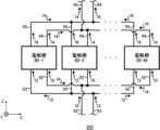
- FIG. 1 is a diagram showing an example of an electrolysis device 200 according to one embodiment of the present invention.
- FIG. 2 is a diagram of the electrolysis device 200 shown in FIG. 1 viewed from the X-axis direction.
- 3 is a diagram showing an example of details of one electrolytic cell 91 in FIG. 2.
- FIG. 4 is an enlarged view of the vicinity of the ion exchange membrane 84 in the electrolytic cell 91 shown in FIG. 3.
- FIG. 1 is a diagram showing an example of a block diagram of a driving support device 100 according to an embodiment of the present invention.
- FIG. 3 is an image diagram showing an example of driving support for the electrolytic cell 90 by the driving support device 100.
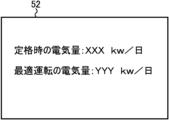
- 5 is a diagram illustrating an example of a display format by a display unit 52.
- FIG. 1 is a diagram showing an example of a display format by a display unit 52.
- FIG. 5 is a diagram illustrating another example of a display form by the display unit 52.
- FIG. It is a figure which shows an example of the relationship between the electrical cost accompanying the operation
- FIG. 5 is a diagram illustrating currents of a plurality of electrolytic cells 90, etc. in calculation of the production amount of product P by the calculation unit 10 (see FIG. 5).
- FIG. 5 is a diagram illustrating another example of a display form by the display unit 52.
- FIG. It is a figure which shows an example of the relationship between the electrical cost accompanying the operation
- FIG. 5 is a diagram illustrating the current of the plurality of electrolytic cells 90 when the plurality of electrolytic cells 90 are integrated into one electrolytic cell 90 in calculating the production amount of the product P by the calculation unit 10 (see FIG. 5). . It is a figure which shows an example of the relationship between the production amount Ac of the product P accompanying the operation
- FIG. 3 is a diagram showing the relationship between the concentration of alkali metal chloride in the liquid 75 (see FIG. 3) and the second current value flowing through the electrolytic cell 90 for a plurality of current efficiencies CE.
- FIG. 5 is a diagram showing an example of the first current value Iv1 for each time T calculated by the calculation unit 10 (see FIG. 5).
- FIG. It is a figure which shows another example of 1st electric current value Iv1 for every time T calculated by the calculation part 10 (refer FIG. 5).
- 13 is a diagram showing an example of the production amount Ac of the product P produced by each of the plurality of electrolytic cells 90 at time T2 (see FIG. 13).
- FIG. 18 is a diagram showing an example of production amount Ac when the operation of electrolytic cell 90-1 is stopped in the example of FIG. 17.
- FIG. 1 is a flowchart illustrating an example of a driving support method according to an embodiment of the present invention.
- FIG. 1 is a flowchart illustrating an example of a driving support method according to an embodiment of the present invention.
- 20 is a flowchart showing an example of details of the stop step S200 in FIG. 19.
- 1 is a flowchart illustrating an example of a driving support method according to an embodiment of the present invention.
- FIG. 3 is a diagram illustrating an example of a computer 2200 in which the driving assistance device 100 according to an embodiment of the present invention may be implemented in whole or in part.
- FIG. 1 is a diagram showing an example of an electrolysis device 200 according to one embodiment of the present invention.
- the electrolysis device 200 is a device that electrolyzes an electrolytic solution.
- Electrolyzer 200 includes a plurality of electrolytic cells 90.
- the electrolyzer 200 includes electrolytic cells 90-1 to 90-M (M is an integer of 2 or more).
- the plurality of electrolytic cells 90 operate in parallel.
- the plurality of electrolytic cells 90 operating in parallel refers to the plurality of electrolytic cells 90 electrolyzing the electrolyte solution in parallel.
- the electrolytic cell 90 is a cell that electrolyzes an electrolytic solution.
- the electrolysis device 200 of this example includes an introduction pipe 92, an introduction pipe 93, an outlet pipe 94, and an outlet pipe 95.
- the introduction pipe 92 and the introduction pipe 93 are connected to each of the plurality of electrolytic cells 90.
- the outlet pipe 94 and the outlet pipe 95 are connected to each of the plurality of electrolytic cells 90.
- a liquid 70 and a liquid 72 are introduced into each of the plurality of electrolytic cells 90.
- a liquid 76 and a gas 78 (described later) are led out from each of the plurality of electrolytic cells 90.
- a liquid 74 and a gas 77 (described later) are led out from each of the plurality of electrolytic cells 90.
- the plurality of electrolytic cells 90 are arranged in a predetermined direction.
- the predetermined arrangement direction of the plurality of electrolytic cells 90 is defined as the X-axis direction.
- the direction perpendicular to the X-axis direction and heading from the introduction tube 92 to the outlet tube 94 is defined as the Z-axis.
- the direction perpendicular to the X-axis and perpendicular to the Z-axis direction is referred to as the Y-axis.
- the Z-axis direction may be parallel to the vertical direction, and the XY plane may be a horizontal plane.
- the electrolytic solution electrolyzed in the electrolytic cell 90 is, for example, a NaCl (sodium chloride) aqueous solution or KCl (potassium chloride).
- a NaCl (sodium chloride) aqueous solution or KCl (potassium chloride) is referred to as salt electrolysis.
- the electrolytic cell 90 In the case of salt electrolysis, the electrolytic cell 90 generates Cl 2 (chlorine) by electrolyzing a NaCl (sodium chloride) aqueous solution or KCl (potassium chloride) in an anode chamber 79 (described later), and generates Cl 2 (chlorine) in a cathode chamber 98 (described later).
- Cl 2 chlorine
- H 2 O water
- an aqueous solution of NaOH (sodium hydroxide) or KOH (potassium hydroxide) and H 2 (hydrogen) are generated.
- the electrolytic solution electrolyzed in the electrolytic cell 90 may be a NaOH (sodium hydroxide) aqueous solution or a KOH (potassium hydroxide) aqueous solution.
- the electrolyte is an aqueous NaOH (sodium hydroxide) solution or an aqueous KOH (potassium hydroxide) solution is referred to as alkaline water electrolysis.
- the electrolytic cell 90 generates O 2 (oxygen) and H 2 (hydrogen) by electrolyzing a NaOH (sodium hydroxide) aqueous solution or a KOH (potassium hydroxide) aqueous solution.
- FIG. 2 is a diagram of the electrolysis device 200 shown in FIG. 1 viewed from the X-axis direction.
- One electrolytic cell 90-M in FIG. 1 will be explained as an example.
- One electrolytic cell 90 may include a plurality of electrolytic cells 91.
- one electrolytic cell 90 includes electrolytic cells 91-1 to 91-N (N is an integer of 2 or more). N is, for example, 50.
- each of electrolytic cells 90-1 to 90-M includes a plurality of electrolytic cells 91.
- the introduction pipe 92 and the introduction pipe 93 are connected to each of the electrolytic cells 91-1 to 91-N.
- the liquid 70 is introduced into each of the electrolytic cells 91-1 to 91-N. After passing through the introduction pipe 92, the liquid 70 may be introduced into each of the electrolytic cells 91-1 to 91-N.
- Liquid 70 is an aqueous solution of alkali metal chloride. Alkali metals are elements belonging to Group 1 of the periodic table of elements.
- the liquid 70 is an aqueous solution of NaCl (sodium chloride) or KCl (potassium chloride).
- the liquid 70 is a NaOH (sodium hydroxide) aqueous solution or a KOH (potassium hydroxide) aqueous solution.
- a liquid 72 is introduced into each of the electrolytic cells 91-1 to 91-N. After passing through the introduction pipe 93, the liquid 72 may be introduced into each of the electrolytic cells 91-1 to 91-N.
- the liquid 72 is an aqueous solution of an alkali metal hydroxide.
- the liquid 72 is an aqueous NaOH (sodium hydroxide) solution.
- the liquid 72 is a NaOH (sodium hydroxide) aqueous solution or a KOH (potassium hydroxide) aqueous solution.
- the outlet pipe 94 and the outlet pipe 95 are connected to each of the electrolytic cells 91-1 to 91-N.
- a liquid 76 and a gas 78 (described later) are led out from each of the electrolytic cells 91-1 to 91-N.
- the liquid 76 and the gas 78 (described later) may be led out of the electrolyzer 200 after passing through the lead-out pipe 95.
- Liquid 76 is an aqueous solution of alkali metal hydroxide.
- the liquid 72 is an aqueous NaOH (sodium hydroxide) solution
- the liquid 76 is an aqueous NaOH (sodium hydroxide) solution.
- the liquid 72 is a KOH (potassium hydroxide) aqueous solution
- the liquid 76 is a KOH (potassium hydroxide) aqueous solution.
- Gas 78 (described below) may be H 2 (hydrogen).
- a liquid 74 and a gas 77 are led out from each of the electrolytic cells 91-1 to 91-N.
- the liquid 74 and the gas 77 may be led out of the electrolyzer 200 after passing through the lead-out pipe 94.
- the liquid 74 is an aqueous solution of an alkali metal chloride.
- liquid 70 is an aqueous solution of NaCl (sodium chloride) or potassium chloride (KCl)
- liquid 74 is an aqueous solution of NaCl (sodium chloride) or KCl (potassium chloride).
- Gas 77 (described below) may be Cl 2 (chlorine).
- the liquid 74 is an aqueous NaOH (sodium hydroxide) solution.
- the liquid 74 is a KOH (potassium hydroxide) aqueous solution.
- the gas 77 (described below) may be O 2 (oxygen).
- FIG. 3 is a diagram showing an example of details of one electrolytic cell 91 in FIG. 2.
- Electrolytic cell 90 has an anode chamber 79, an anode 80, a cathode chamber 98, a cathode 82, and an ion exchange membrane 84.
- one electrolytic cell 91 has an anode chamber 79, an anode 80, a cathode chamber 98, a cathode 82, and an ion exchange membrane 84.
- the anode chamber 79 and the cathode chamber 98 are provided inside the electrolytic cell 91.
- the anode chamber 79 and the cathode chamber 98 are separated by an ion exchange membrane 84.
- An anode 80 is placed in the anode chamber 79 .
- a cathode 82 is arranged in the cathode chamber 98 .
- An inlet pipe 92 and an outlet pipe 94 are connected to the anode chamber 79.
- An inlet pipe 93 and an outlet pipe 95 are connected to the cathode chamber 98 .
- a liquid 70 is introduced into the anode chamber 79 .
- Liquid 72 is introduced into cathode chamber 98 .
- the ion exchange membrane 84 is a membrane-like substance that blocks the passage of ions having the same sign as the ions arranged in the ion exchange membrane 84 and allows the passage of ions of the opposite sign.
- the ion exchange membrane 84 is a membrane that allows Na + (sodium ions) or K + (potassium ions) to pass through and blocks Cl - (chloride ions) from passing through.
- the ion exchange membrane 84 is a membrane that allows Na + (sodium ions) or K + (potassium ions) to pass through and blocks OH - (hydroxide ions) from passing through.
- Anode 80 and cathode 82 may be maintained at predetermined positive and negative potentials, respectively.
- the liquid 70 introduced into the anode chamber 79 and the liquid 72 introduced into the cathode chamber 98 are electrolyzed by the potential difference between the anode 80 and the cathode 82.
- salt electrolysis and alkaline water electrolysis the following chemical reaction occurs at the anode 80.
- [Chemical formula 1-2] Alkaline water electrolysis) 4OH - ⁇ O 2 +2H 2 O+4e -
- NaOH sodium hydroxide
- NaOH sodium hydroxide
- OH - hydrooxide ions
- H 2 O water
- O 2 oxygen
- Gas 77 the O 2 (oxygen) gas
- liquid 74 may be led out from anode chamber 79 .
- Na + (sodium ions) move from the anode chamber 79 to the cathode chamber 98 after passing through the ion exchange membrane 84 due to the attractive force from the cathode 82 .
- the liquid 73 may remain in the anode chamber 79 .
- the liquid 73 is an aqueous solution of an alkali metal chloride.
- liquid 73 is an aqueous NaCl (sodium chloride) solution.
- the Na + (sodium ion) concentration and the Cl ⁇ (chloride ion) concentration of the liquid 73 may be lower than the Na + (sodium ion) concentration and the Cl ⁇ (chloride ion) concentration of the liquid 70, respectively.
- the liquid 73 may be a KCl (potassium chloride) aqueous solution.
- the K + (potassium ion) concentration and the Cl ⁇ (chloride ion) concentration of the liquid 73 may be lower than the K + (potassium ion) concentration and the Cl ⁇ (chloride ion) concentration of the liquid 70, respectively.
- the liquid 73 is a NaOH (sodium hydroxide) aqueous solution or a KOH (potassium hydroxide) aqueous solution.
- a concentration sensor 99 may be provided in the cathode chamber 98. Concentration sensor 99 measures the concentration of alkali metal chloride in liquid 75 .
- the electrolytic cell 90 may be provided with a temperature sensor 97 that measures the temperature of the electrolyte that the electrolytic cell 90 decomposes.
- temperature sensor 97 is provided in cathode chamber 98.
- liquid 72 When the liquid 72 is an aqueous solution of NaOH (sodium hydroxide), NaOH (sodium hydroxide) is ionized into Na + (sodium ions) and OH - (hydroxide ions).
- NaOH sodium hydroxide
- KOH potassium hydroxide
- KOH potassium hydroxide
- K + potassium ion
- OH - hydrooxide ion
- H 2 (hydrogen) gas and OH - (hydroxide ions) are generated by the chemical reaction shown in Chemical Formula 2.
- Gas 78 such as H 2 (hydrogen) gas
- liquid 76 may be led out of cathode chamber 98 .
- the liquid 75 may remain in the cathode chamber 98 .
- the liquid 75 is an aqueous solution of an alkali metal hydroxide.
- the liquid 75 is an aqueous solution of NaOH (sodium hydroxide) or aqueous KOH (potassium hydroxide).
- the cathode chamber 98 contains OH ⁇ (hydroxide ions) generated by the chemical reaction shown in Chemical Formula 2, and Na + (sodium ions) or K + (potassium ions) transferred from the anode chamber 79.
- a liquid 75 in which and is dissolved remains.
- a product produced by the plurality of electrolytic cells 90 is referred to as a product P.
- the product P is NaOH (sodium hydroxide) or Cl2 (chlorine).
- the product P is KOH (potassium hydroxide) or Cl 2 (chlorine).
- the liquids 70 and 72 are NaOH (sodium hydroxide) aqueous solutions (in the case of alkaline water electrolysis)
- the product P is H 2 (hydrogen).
- FIG. 4 is an enlarged view of the vicinity of the ion exchange membrane 84 in the electrolytic cell 91 shown in FIG.
- Anion groups 86 are fixed to the ion exchange membrane 84 of this example. Anions are repelled by the anion groups 86, so they are difficult to pass through the ion exchange membrane 84.
- the anion is Cl ⁇ (chloride ion). Since the cations 71 are not repelled by the anion groups 86, they can pass through the ion exchange membrane 84.
- the liquid 70 (see FIG. 3) is an aqueous NaCl (sodium chloride) solution, the cation 71 is Na + (sodium ion).
- the KCl (potassium chloride) aqueous solution the cation 71 is K + (potassium ion).
- FIG. 5 is a diagram showing an example of a block diagram of the driving support device 100 according to one embodiment of the present invention.
- the operation support device 100 supports the operation of the electrolyzer 200 (see FIG. 2).
- the driving support device 100 includes a calculation section 10, a specification section 20, a determination section 30, and a control section 40.
- the driving support device 100 may include an input section 50, a display section 52, and a storage section 60.
- the driving support device 100 is, for example, a computer including a CPU, a memory, an interface, and the like.
- the control unit 40 may be the CPU.
- the calculation unit 10, the identification unit 20, the determination unit 30, and the control unit 40 may be one CPU.
- a driving support program may be installed in the computer in order to execute a driving support method to be described later, and a driving support program for causing the computer to function as the driving support device 100 may be installed. May be installed.
- the input unit 50 is, for example, a keyboard, a mouse, or the like.
- the display unit 52 is, for example, a display, a monitor, or the like.
- FIG. 6 is an image diagram showing an example of operation support for the electrolytic cell 90 by the operation support device 100.
- the electrolyzer 200 (see FIG. 1) has a terminal 210.
- the terminal 210 is, for example, a distributed control system (DCS).
- the terminal 210 and the driving support device 100 may communicate wirelessly or may communicate by wire.
- the terminal 210 transmits operational data related to the operation of the electrolyzer 200 to the driving support device 100.
- the driving support device 100 transmits instruction data such as the current value to be passed through the electrolytic cell 90 to the terminal 210.
- the display unit 52 displays parameters related to the control of the electrolysis device 200.
- the parameters include, for example, current efficiency CE (described later), voltage CV (described later), and the like.
- FIG. 7 is a diagram showing an example of a display format by the display unit 52.
- the display unit 52 displays the amount of electricity at the rated time and the amount of electricity at the optimum operation.
- the display unit 52 may further display power consumption amount Ec (described later) for each time T.
- FIG. 8 is a diagram showing another example of the display form by the display unit 52.
- the operating status of each electrolytic cell 90 is displayed on the display section 52.
- the display unit 52 displays guidance regarding stopping the tank for the user of the driving support device 100.
- the guidance regarding stopping the electrolytic cell 90 is guidance regarding stopping the operation of the electrolytic cell 90.
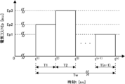
- FIG. 9 is a diagram illustrating an example of the relationship between the electrical cost associated with the operation of a plurality of electrolytic cells 90 operating in parallel and the time t at which the plurality of electrolytic cells 90 operate.
- the electricity cost is referred to as electricity cost Ep.
- Time T is a period between one time t and another time t' after the one time t, during which the plurality of electrolytic cells 90 operate.
- the period of time T may be predetermined.
- the period from time t (1) to time t (2) is time T1
- the period from time t (2) to time t (3) is time T2
- time t (n-1) to Let the period of time t (n) be time T (n-1).
- the electricity cost Ep may be expressed as a monetary amount, may be expressed as the amount of power consumed by the operation of the plurality of electrolytic cells 90 operating in parallel, or may be expressed as an amount in other units.
- the power consumption amount is referred to as power consumption amount Ec.
- the electricity cost Ep may be a value obtained by converting the sum of a plurality of types of costs into a monetary amount.
- FIG. 9 shows an example of the relationship between the power consumption amount Ec and the time t at which the plurality of electrolytic cells 90 operate.
- the electricity cost Ep may vary depending on the time T.
- the electricity cost Ep at time T1 is assumed to be electricity cost Ep2
- the electricity cost Ep at time T2 is assumed to be electricity cost Ep3
- the electricity cost Ep at time T3 is assumed to be electricity cost Ep1.
- the electricity cost Ep1 is smaller than the electricity cost Ep2, and the electricity cost Ep2 is smaller than the electricity cost Ep3.
- the time T1 is, for example, early in the morning.
- Time T2 is, for example, a time during the day.
- Time T3 is, for example, midnight.
- the electricity cost Ep for each time T may be input through the input unit 50.
- FIG. 10 is a diagram showing an example of the power consumption amount Ec and the suppliable power amount Es for each time T.
- the suppliable power amount Es may refer to the maximum value of the power amount that can be supplied to the plurality of electrolytic cells 90 in one time T.
- the supplyable power Es is the maximum amount of power that can be distributed to the electrolyzer 200 when the factory supplies power to multiple devices including the electrolyzer 200. It may be electricity.
- the determination unit 30 may determine the magnitude of the power consumption Ec and the suppliable power amount Es at each time T. In the example of FIG. 10, the determining unit 30 determines that the power consumption amount Ec is less than the suppliable power amount Es at time T1, and the power consumption amount Ec is less than the suppliable power amount Es at time T1 and time T(n-1). It is judged that it exceeds.
- the identifying unit 20 may identify one time T when the power consumption amount Ec is less than the suppliable power amount Es and another time T when the power consumption amount Ec is greater than or equal to the suppliable power amount Es. In the example of FIG. 10, the specifying unit 20 specifies time T1 as one time T, and specifies at least one of time T2 and time T(n-1) as another time T.
- the calculation unit 10 may calculate the surplus power amount, which is the difference between the suppliable power amount Es and the power consumption amount Ec, at one time T.
- the surplus power amount is referred to as surplus power amount Em.
- the calculation unit 10 calculates the surplus power amount Em at time T1.
- the control unit 40 may control the power supplied to the electrolytic cell 90 to include the surplus power Em at other times T when the power consumption Ec is determined to be equal to or greater than the suppliable power amount Es.
- the power including the surplus power amount Em may be the power amount obtained by adding the surplus power amount Em to the suppliable power amount Es.
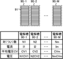
- FIG. 11 is a diagram illustrating the currents of the plurality of electrolytic cells 90, etc. in calculation of the production amount of the product P by the calculation unit 10 (see FIG. 5).
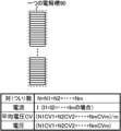
- the number of pairs of electrolytic cells 91 (see FIG. 2) in each of electrolytic cells 90-1 to 90-M is set to N1 to Nm, respectively.
- the number of pairs is the number of pairs of anode chambers 79 and cathode chambers 98 in one electrolytic cell 91.
- the number of pairs in one electrolytic cell 91 is equal to the number of ion exchange membranes 84 (see FIG. 3) in one electrolytic cell 91.
- the currents flowing through each of the electrolytic cells 90-1 to 90-M are defined as current I1 to current Im.
- the voltages of electrolytic cells 90-1 to 90-M are set to voltage CV1 to voltage CVm, respectively. As shown in FIG. 11, the voltages of electrolytic cells 90-1 to 90-M are N1CV1 to NmCVm, respectively.
- FIG. 12 explains the current etc. of the plurality of electrolytic cells 90 when the plurality of electrolytic cells 90 are integrated into one electrolytic cell 90 in calculating the production amount of the product P by the calculation unit 10 (see FIG. 5).
- This is a diagram. Integrating a plurality of electrolytic cells 90 into one electrolytic cell refers to considering a plurality of electrolytic cells 90 as one electrolytic cell 90.
- calculation unit 10 integrates electrolytic cells 90-1 to 90-M into one electrolytic cell 90.
- the number N of pairs in one electrolytic cell 90 is expressed by the following formula (1). That is, the number of pairs N is the sum of the logarithms N1 to Nm.
- the average voltage CV of the electrolytic cells 90 integrated into one electrolytic cell 90 is expressed by the following formula (2). That is, the average voltage CV is expressed as a weighted average of N pairs.
- the target production amount of the product P be the target production amount At.
- the target production amount At is the target production amount of the product P produced by the plurality of electrolytic cells 90 over a predetermined period.
- the predetermined period is referred to as a period Tw.
- the period Tw is the sum of time T1 to time T(n-1).
- period Tw is 24 hours.
- the target production amount At may be input through the input unit 50.
- the calculation unit 10 calculates the production amount of the product P for each time T that satisfies the target production amount At based on the electricity cost Ep or the power consumption Ec for each predetermined time T. .
- the production amount calculated by the calculation unit 10 is defined as production amount Ac.
- the calculation unit 10 calculates the production amount Ac for the electrolytic cells 90 integrated into one electrolytic cell 90 in FIG.
- the calculation unit 10 also calculates first current values Iv1 to fourth current values Iv4, which will be described later, for the electrolytic cells 90 integrated into one electrolytic cell 90 in FIG.
- the specifying unit 20 (see FIG. 5) specifies the operating electrolytic cell 90 among the plurality of electrolytic cells 90 based on the production amount Ac calculated by the calculating unit 10.
- the control unit 40 controls the current flowing through the operating electrolytic cell 90 specified by the specifying unit 20.
- the identification unit 20 may identify the electrolytic cell 90 to be stopped among the plurality of electrolytic cells 90.
- the control unit 40 may control the current flowing through the electrolytic cell 90 that is stopped to be smaller than the current flowing through the electrolytic cell 90 that is not stopped.
- the control unit 40 may set the current flowing through the electrolytic cell 90 to be stopped to zero.
- the calculation unit 10 may calculate the first current value to be passed through the plurality of electrolytic cells 90 for each time T based on the production amount Ac.
- the first current value is referred to as a first current value Iv1.
- the calculation unit 10 may calculate the first current value Iv1 to be passed through the electrolytic cell 90 that is not stopped when the current that is passed through the electrolytic cell 90 that is to be stopped is zero.
- FIG. 13 is a diagram showing an example of the relationship between the production amount Ac of the product P and the time T during which the plurality of electrolytic cells 90 operate in parallel.
- the production amount Ac may vary depending on the time T.
- the production amount Ac at time T1 is set as production amount Ac2
- the production amount Ac at time T2 is set as production amount Ac1
- the production amount Ac at time T(n-1) is set as production amount Ac3.
- the production amount Ac1 is smaller than the production amount Ac2
- the production amount Ac2 is smaller than the production amount Ac3.
- the electricity cost Ep at time T1 is the electricity cost Ep (1)
- the electricity cost Ep at time T2 is the electricity cost Ep (2)
- the electricity cost Ep at time T(n-1) is the electricity cost Let Ep (n-1) .
- the current efficiency of the electrolytic cell 90 is defined as current efficiency CE.
- the current efficiency CE refers to the ratio of the actual production amount to the theoretical production amount of the product P.
- the sum of the production amounts Ac of the product P over the period Tw is defined as the total production amount Acs.
- the total production amount Acs is expressed by the following formula (3).
- the total electricity cost Ep over the period Tw is defined as the total electricity cost Eps.
- the total electricity cost Eps is expressed by the following formula (4).
- the current value I (j) is expressed by the following equation (6).
- the calculation unit 10 may calculate the first current value Iv1 based on the above equation (6).
- the calculation unit 10 may calculate the production amount Ac that satisfies the target production amount At of the product P over the period Tw and minimizes the electricity cost Ep or the power consumption Ec over the period Tw.
- the calculation unit 10 sets the total production amount Acs in equation (3) to the target production amount At, and calculates the production amount Ac that minimizes the total electricity cost Eps in equation (4) based on equations (3) to (6). You can calculate it using
- the specifying unit 20 may specify which electrolytic cell 90 is to be operated among the plurality of electrolytic cells 90 based on the production amount Ac that minimizes the electricity cost Ep.
- FIG. 14 is a diagram showing the relationship between the concentration of alkali metal chloride in the liquid 75 (see FIG. 3) and the second current value flowing through the electrolytic cell 90 for a plurality of current efficiencies CE.
- the second current value is referred to as a second current value Iv2.
- the impurity concentration which is an index of the quality of the product P, be the concentration Cs.
- the concentration Cs may refer to the NaCl (sodium chloride), NaClO 3 (sodium chlorate) concentration or HClO (hypochlorous acid) concentration in the product P.
- the concentration Cs may refer to the O 2 (oxygen) concentration in the product P.
- the concentration Cs may refer to the KCl (potassium chloride) concentration, KClO 3 (potassium chlorate) concentration or KClO (potassium hypochlorite) concentration in the product P .
- the concentration Cs is the concentration of alkali metal chloride in the aqueous solution of product P (liquid 75).
- the concentration Cs may be measured by a concentration sensor 99 (see FIG. 4).
- the identification unit 20 (see FIG. 5) may acquire the concentration Cs measured by the concentration sensor 99.
- the flow rate of the product P (H 2 (hydrogen)) is represented by FL.
- FL is the flow rate of gas 78.
- the flow rate FL may be measured by a flow sensor.
- Am be the theoretical amount of gas 78 generated based on the current I.
- Ls be the theoretical loss amount of the product P (H 2 (hydrogen)) based on the concentration (concentration Cs) of H 2 (hydrogen) in the gas 77 (O 2 (oxygen)).
- Current efficiency CE in the case of alkaline water electrolysis is expressed by the following formula (7-1) or formula (7-2).
- the relationship between the concentration Cs and the current value shown in FIG. 14 may be obtained by measuring the change in the concentration Cs when the current value is changed.
- the concentration Cs tends to decrease as the current value increases.
- the maximum current efficiency CE among the current efficiencies CE1 to CE5 is the current efficiency CE1
- the minimum current efficiency CE is the current efficiency CE5.
- the concentration Cs tends to decrease as the current efficiency CE decreases.
- the second current value Iv2 is a current value for satisfying a predetermined quality of the product P.
- the second current value Iv2 may be the minimum current value to satisfy the quality.
- the relationship between the concentration Cs and the second current value Iv2 shown in FIG. 14 may be obtained in advance.
- the relationship between the concentration Cs and the second current value Iv2 obtained in advance may be stored in the storage unit 60.
- the calculation unit 10 may calculate the second current value Iv2 to be caused to flow through the plurality of electrolytic cells 90 based on the concentration Cs.
- the calculation unit 10 may calculate the second current value Iv2 by fitting the relationship between the concentration Cs and the second current value Iv2 shown in FIG. 14 to the following equation (8).
- F is a constant.
- F is, for example, 10.8.
- At least one of the first current value Iv1 and the second current value Iv2 may be determined based on the temperature of the electrolytic solution.
- the temperature of the electrolyte may be measured by a temperature sensor 97 (see FIG. 3).
- the performance of the electrolytic cell 90 may vary depending on the temperature of the electrolytic solution and at least one of the first current value Iv1 and the second current value Iv2. Therefore, at least one of the first current value Iv1 and the second current value Iv2 may be determined based on the temperature of the electrolytic solution.
- the determination unit 30 may determine the magnitude of the first current value Iv1 and the second current value Iv2 for each time T calculated by the calculation unit 10 (see FIG. 5).
- the determination unit 30 may determine the magnitude of the first current value Iv1 for each time T and a predetermined fourth current value to be passed through the plurality of electrolytic cells 90.
- the fourth current value is referred to as a fourth current value Iv4.
- the fourth current value Iv4 may be the maximum current value that can flow through the plurality of electrolytic cells 90.
- the maximum current value is, for example, 16.2 kA.
- At least one time T from time T1 to time T(n-1) is defined as a first time Ta1, and the at least one time T different from the first time Ta1 is defined as a second time Ta2.
- the identification unit 20 may identify one electrolytic cell 90 to be stopped among the plurality of electrolytic cells 90.
- the one electrolytic cell 90 may be any one electrolytic cell 90 among the plurality of electrolytic cells 90, or may be any two or more electrolytic cells 90.
- the determining unit 30 determines that the first current value Iv1 is may refer to the case where it is determined that the current value Iv4 is equal to or less than the fourth current value Iv4.
- the determination unit 30 determines that the first current value Iv1 is greater than or equal to the second current value Iv2, and determines that the first current value Iv1 is greater than the fourth current value Iv4 at the second time Ta2.
- the specifying unit 20 may specify one electrolytic cell 90 to be stopped among the plurality of electrolytic cells 90.
- the case where the first current value Iv1 is determined by the determining unit 30 to be equal to or higher than the second current value Iv2 means that the first current value Iv1 is determined by the determining unit 30 to be equal to may refer to the case where it is determined that the current value Iv2 is greater than or equal to the second current value Iv2.
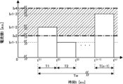
- FIG. 15 is a diagram showing an example of the first current value Iv1 for each time T calculated by the calculation unit 10 (see FIG. 5).
- the first current value Iv1 at time T1 is the first current value Iv1-1
- the first current value Iv1 at time T2 is the first current value Iv1-2
- the first current value Iv1 at time T(n-1) is the first current value Iv1-1.
- the current value Iv1 is set as a first current value Iv1-3.
- FIG. 15 also shows the second current value Iv2 and the fourth current value Iv4 described above. In FIG. 15, the range from the second current value Iv2 to the fourth current value Iv4 is indicated by hatching.
- the first current value Iv1-2 and the first current value Iv1-3 are greater than or equal to the second current value Iv2 and less than or equal to the fourth current value Iv4, and the first current value Iv1-1 is less than the second current value Iv2.
- the specifying unit 20 may specify the time T at which the production amount Ac is the smallest. In the example of FIG. 13, the specifying unit 20 specifies time T2 as the time T when the production amount Ac is the smallest. In this example, the first time Ta1 is time T2. In this example, the specifying unit 20 (see FIG. 5) specifies one electrolytic cell 90 to be stopped among the plurality of electrolytic cells 90 at time T2.
- the control unit 40 controls the The current flowing through the tank 90 may be controlled to the first current value Iv1.
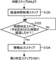
- the determination unit 30 may acquire the elapsed time since the first current value Iv1 was determined to be greater than or equal to the second current value Iv2 and less than or equal to the fourth current value.
- the elapsed time is referred to as elapsed time Ts.
- the determination unit 30 may determine the magnitude of the elapsed time Ts and a predetermined time.
- the predetermined time is defined as time Tp.
- the time Tp may be a period from when it is determined whether or not to change the operating conditions of the electrolytic cell 90 to when it is next determined whether or not to change the operating conditions of the electrolytic cell 90.
- the time Tp may be the time Tw shown in FIGS. 13 and 15.
- the operating conditions of the electrolytic cell 90 are defined as operating conditions Cd.
- the operating conditions Cd may include at least one of current efficiency CE, voltage CV, electricity cost Ep, target production amount At, and the length of each time from time T1 to time T(n-1).
- the control unit 40 When the determination unit 30 (see FIG. 5) determines that the elapsed time Ts is greater than the time Tp, the control unit 40 (see FIG. 5) outputs information regarding whether or not to change the operating condition Cd. good.
- the control unit 40 outputting the information may mean that the control unit 40 causes the display unit 52 (see FIG. 5) to display the information.
- FIG. 16 is a diagram showing another example of the first current value Iv1 for each time T calculated by the calculation unit 10 (see FIG. 5).
- the first current value Iv1-3 is larger than the fourth current value Iv4.
- the second time Ta2 is time T(n-1).
- the determining unit 30 determines that the first current value Iv1 is less than the second current value Iv2 at the first time Ta1, and the first current value Iv1 is less than the fourth current value Iv4 at the second time Ta2. If it is determined that the current flowing through the plurality of electrolytic cells 90 is large at the first time Ta1, the calculation unit 10 (see FIG. 5) sets the current flowing through the plurality of electrolytic cells 90 at the first time Ta1 to the second current value Iv2, or sets the current flowing through the plurality of electrolytic cells 90 at the second time Ta2. The current value flowing through the plurality of electrolytic cells 90 may be further calculated for each time T by setting the current flowing through the electrolytic cell 90 as the fourth current value Iv4.
- the difference between the second current value Iv2 and the first current value Iv1 at the first time Ta1 is defined as a first difference df1.
- the first difference df1 is Iv2-Iv1.
- the difference between the first current value Iv1 and the fourth current value Iv4 at the second time Ta is defined as a second difference df2.
- the second difference df2 is Iv1-Iv4.
- the determination unit 30 may determine the magnitude of the first difference df1 at the first time Ta1 and the second difference df2 at the second time Ta2. If the determining unit 30 determines that the first difference df1 is larger than the second difference df2, the calculating unit 10 (see FIG. 5) converts the current flowing through the plurality of electrolytic cells 90 at the first time Ta1 into a second current. The current value may be further calculated at each time T as the value Iv2.
- the calculating unit 10 sets the current flowing through the plurality of electrolytic cells 90 at the second time Ta2 as a fourth current value Iv4, and calculates the current The value may be further calculated at each time T.
- the second difference df2 is larger than the first difference df1. Therefore, the calculation unit 10 further calculates the current value for each time T, with the current flowing through the plurality of electrolytic cells 90 at the second time Ta2 as the fourth current value Iv4.
- FIG. 17 is a diagram showing an example of the production amount Ac of the product P produced by each of the plurality of electrolytic cells 90 at time T2 (see FIG. 13).
- the case where the number of the plurality of electrolytic cells 90 shown in FIG. 1 is three (M 3) will be described as an example.
- the current efficiencies CE of the electrolytic cells 90-1 to 90-3 are current efficiencies CE1 to CE3, respectively. It is assumed that current efficiency CE3 is larger than current efficiency CE2, and current efficiency CE2 is larger than current efficiency CE1.
- the production quantities Ac of the electrolytic cells 90-1 to 90-3 are production quantities Ac1-1 to production quantities Ac1-3, respectively. It is assumed that the production amount Ac1-3 is larger than the production amount Ac1-2, and the production amount Ac1-2 is larger than the production amount Ac1-1.
- the identification unit 20 may identify the electrolytic cell 90 with the smallest production amount Ac as the one electrolytic cell 90 to be stopped.
- the specifying unit 20 specifies the electrolytic cell 90-1 to be stopped.
- the identification unit 20 may identify one or more electrolytic cells 90 among the plurality of electrolytic cells 90 as one electrolytic cell 90 to be stopped.
- the identification unit 20 may identify the electrolytic cells 90 to be stopped in descending order of the obtained production amount.
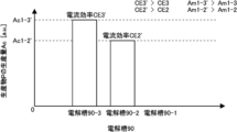
- FIG. 18 is a diagram showing an example of the production amount Ac when the operation of electrolytic cell 90-1 is stopped in the example of FIG. 17.
- the current efficiencies CE of the electrolytic cell 90-2 and the electrolytic cell 90-3 are current efficiency CE2' and current efficiency CE3', respectively.
- the production amount Ac of the electrolytic cell 90-1 and the electrolytic cell 90-2 is a production amount Ac1-2' and a production amount Ac1-3', respectively.
- the calculation unit 10 may further calculate the current value for each time T when the one electrolytic cell 90 specified by the identification unit 20 (see FIG. 5) is stopped. This current value is defined as a third current value Iv3. In this example, the calculation unit 10 further calculates the current value when the operation of the electrolytic cell 90-1 is stopped at each time T.
- the third current value Iv3 may be larger than the first current value Iv1.
- Current efficiency CE2' may be greater than current efficiency CE2 (see FIG. 17).
- Current efficiency CE3' may be greater than current efficiency CE3 (see FIG. 17).
- the production amount Ac1-2' may be larger than the production amount Ac1-2 (see FIG. 17).
- the production amount Ac1-3' may be larger than the production amount Ac1-3 (see FIG. 17).
- the determination unit 30 may determine the magnitude of the third current value Iv3 and the fourth current value Iv4 at each time T.
- the control unit 40 controls the current flowing through the plurality of electrolyzers 90 to the third current value Iv3. It's okay.
- the control unit 40 controls the current flowing through the electrolytic cells 90-2 and 90-3 to the third current Iv3.
- the determination unit 30 may further determine the magnitude relationship between the third current value Iv3 and the second current value Iv2.
- the control unit 40 controls the plurality of electrolytic cells 90.
- the flowing current may be controlled to the third current value Iv3.
- the determining unit 30 determines the magnitude of the third current value Iv3 and the fourth current value Iv4 and the magnitude of the third current value Iv3 and the second current value Iv2 at each time T. good.
- the concentration C ho of the product P is expressed by the following formula (9).
- the concentration Cho is NaOH (sodium hydroxide, so-called caustic soda).
- the concentration Cho is the concentration of KOH (potassium hydroxide).
- V cell is the volume of each pair. In this example, it is assumed that the volume of all pairs is V cell .
- V other is the total volume of each layer such as the subheader and the gas-liquid separation tank.
- Liquid 76 and gas 78 (see FIG. 3) are led from electrolytic cell 90 to the subheader. The liquid 76 and gas 78 led out to the subheader are separated into liquid 76 and gas 78 in the gas-liquid separation tank.
- V tank is the volume of the circulation tank.
- the circulation tank is a tank in which the liquid 76 separated in the above-mentioned gas-liquid separation tank is temporarily stored.
- NC is the number of pairs per one electrolytic cell 90.
- NE is the number of electrolytic cells 90 in the electrolytic device 200.
- NE 1 is the number of electrolytic cells 90 whose operation has been stopped.
- D is the density of the product P (kg/m 3 ).
- t (k) is the waiting time. t (k) may be any time T from time T1 to time T(n-1).
- the concentration Cs (see FIG. 14) is expressed by the following formula (10).
- a predetermined concentration of the product P in the liquid 75 is defined as a first concentration C1.
- the first concentration C1 may be the minimum concentration that guarantees a predetermined quality of the product P.
- the predetermined impurity concentration of the product P be a second concentration C2.
- the second concentration C2 may be the maximum impurity concentration that guarantees a predetermined quality of the product P.
- the determination unit 30 may determine whether the concentration Cho is greater than the first concentration C1.
- the determination unit 30 may determine whether the concentration Cs is less than the second concentration C2.
- the control unit 40 controls the identification unit 20 (see FIG. 5).
- the current flowing through the one electrolytic cell 90 to be stopped which is specified by , may be controlled to be smaller than the current flowing through the other electrolytic cells 90 .
- the liquid 70 and the liquid 72 are stopped.
- the electrolytic cell 90 may be circulated through another electrolytic cell 90.
- the determination unit 30 determines that the concentration Cho is less than or equal to the first concentration C1, or that the concentration Cs is greater than or equal to the second concentration C2, the liquid 73 and the liquid 75 (see FIG. 3) are removed from the stopped electrolysis.
- the tank 90 may be discharged.
- the identification unit 20 determines whether the plurality of electrolytic cells 90 Other electrolytic cells 90 to be stopped may be further specified.
- the other electrolytic cell 90 is a different electrolytic cell 90 from the one electrolytic cell 90 described above.
- the other electrolytic cell 90 may be any one electrolytic cell 90 other than the above-mentioned one electrolytic cell 90 among the plurality of electrolytic cells 90, and may be any two or more electrolytic cells 90. Good too.
- the specifying unit 20 may specify the electrolytic cell 90 with the smallest production amount Ac among the electrolytic cells 90 in operation as other electrolytic cells 90 to be stopped.
- the calculation unit 10 may further calculate the current value when one electrolytic cell 90 and the other electrolytic cell 90 are stopped at each time T as the third current value Iv3.
- the determination unit 30 may determine the magnitude of the third current value Iv3 and the fourth current value Iv4 when one electrolytic cell 90 and the other electrolytic cell 90 are stopped.
- the control unit 40 controls the current flowing through the plurality of electrolytic cells 90 to the third current value Iv3. May be controlled.
- the determination unit 30 may further determine the magnitude of the third current value Iv3 and the second current value Iv2 when one electrolytic cell 90 and the other electrolytic cell 90 are stopped.
- the control unit 40 controls the current flow to the plurality of electrolytic cells 90. The current may be controlled to the third current value Iv3.
- the specifying unit 20 stops.
- the electrolytic cell 90 may be further specified.
- the calculation unit 10 may calculate the current value when the plurality of identified electrolytic cells 90 are stopped.
- the identification unit 20 may further identify the electrolytic cell 90 to be stopped until it is determined that the current value is equal to or higher than the second current value Iv2.
- the calculation section 10 calculates the current flowing through the plurality of electrolytic cells 90 into the first one.
- the current value to be passed through the plurality of electrolytic cells 90 may be further calculated for each time T as the second current value Iv2 or as the fourth current value Iv4.
- the calculation unit 10 may further calculate the current value flowing through the plurality of electrolytic cells 90 at each time T by setting the current flowing in all the electrolytic cells 90 as the second current value Iv2 or as the fourth current value Iv4.
- the calculation unit 10 determines that the third current value Iv3 is larger than the fourth current value Iv4 at at least one time T
- the current flowing through the plurality of electrolytic cells 90 at time T may be set as the fourth current value Iv4, and the current value flowing through the plurality of electrolytic cells 90 may be further calculated for each time T.
- the at least one time T refers to at least one time T from time T1 to time T(n-1) in FIG.
- FIG. 19 is a flowchart illustrating an example of a driving support method according to one embodiment of the present invention.
- An operation support method according to one embodiment of the present invention is an operation support method that supports operation of the electrolytic cell 90 (see FIG. 1).
- the driving support method includes a first calculation step S104 (see FIG. 19).
- the driving support method may include a 0th determination step S100, an electrolytic cell integration step S102, and an input step S88.
- the driving support method includes a second calculation step S106, a third calculation step S108, a first determination step S110, a second determination step S112, a third determination step S114, a control step S116, a fourth determination step S118, and a determination step S94. It's okay.
- the driving support method may include a first current setting step S130, a second current setting step S132, and a third current setting step S136.
- the driving support method may include an elapsed time acquisition step S120, an information output step S124, and a stop step S200.
- the zeroth determination step S100 is a step of determining whether there is a change in the operating condition Cd of the electrolytic cell 90.
- the operating conditions Cd include at least one of current efficiency CE, voltage CV, target production amount At, electricity cost Ep, power consumption Ec, and the length of each time from time T1 to time T(n-1). It's okay.
- the 0th determination step S100 may be a step in which the determination unit 30 (see FIG. 5) determines whether there is a change in the driving condition Cd, and the user of the driving support device 100 determines whether there is a change in the driving condition Cd. It may be a step of determining.
- the driving support method proceeds to input step S88. If it is not determined in the 0th determination step S100 that there is a change in the operating condition Cd, the operation support method proceeds to the electrolytic cell integration step S102.
- the input step S88 is a step of inputting input parameters to the driving support device 100 (see FIG. 5).
- the input step S88 may be a step in which the user of the driving support device 100 inputs the driving condition Cd through the input unit 50 (see FIG. 5).
- the electrolytic cell integration step S102 is a step in which the calculation unit 10 (see FIG. 5) integrates a plurality of electrolytic cells 90 into one electrolytic cell 90 (see FIGS. 11 and 12) in calculating the production amount of the product P. It is. In this example, the calculation unit 10 integrates the electrolytic cells 90-1 to 90-M into one electrolytic cell 90.
- the first calculation step S104 may include a zeroth calculation step S90 and a determination step S92.
- the calculation unit 10 calculates the product P for each predetermined time T when the fourth current value Iv4 is passed through the plurality of electrolytic cells 90 operating in parallel. This is a step of calculating the production amount Ac.
- the 0th calculation step S90 may be a step in which the calculation unit 10 calculates the production amount Ac for each time T when the fourth current value Iv4 is passed through all the electrolytic cells 90 operating in parallel.
- Determination step S92 is a step in which the determination unit 30 (see FIG. 5) determines whether the production amount Ac satisfies the target production amount At.
- the driving support method proceeds to the second calculation step S106. If it is not determined in the determination step S92 that the production amount Ac satisfies the target production amount At, the driving support method returns to the input step S88.
- the calculation unit 10 in the first calculation step S104, the calculation unit 10 (see FIG. 5) satisfies the target production amount At over the period Tw (see FIGS. 9 and 13), and minimizes the electricity cost Ep or the power consumption Ec over the period Tw. This may be a step of calculating the production amount P to be made.
- the second calculation step S106 is a step in which the calculation unit 10 (see FIG. 5) calculates the first current value Iv1 to be passed through the plurality of electrolytic cells 90 for each time T based on the production amount Ac of the product P.
- the calculation unit 10 calculates the second This is a step of calculating the current value Iv2.
- the second current value Iv2 may be a minimum current value for satisfying a predetermined quality of the product P.
- the determination unit 30 determines the first current value Iv1 for each time T calculated in the second calculation step S106 and the second current value calculated in the third calculation step S108. This is a step of determining the magnitude with respect to Iv2. If it is determined in the first determination step S110 that the first current value Iv1 at the first time Ta1 is less than the second current value Iv2, the driving support method proceeds to the second determination step S112. As described above, the first time Ta1 is at least one time T from time T1 to time T(n-1) (see FIG. 9 and FIG. 13). If it is determined in the first determination step S110 that the first current value Iv1 is greater than or equal to the second current value Iv2, the driving support method proceeds to a third determination step S114.
- the second determination step S112 is a step in which the determination unit 30 (see FIG. 5) determines the magnitude of the first current value Iv1 for each time T calculated in the second calculation step S106 and the fourth current value Iv4. be. If it is determined in the second determination step S112 that the first current value Iv1 is equal to or less than the fourth current value Iv4, the driving support method proceeds to a stop step S200. If it is determined in the second determination step S112 that the first current value Iv1 is larger than the fourth current value Iv4, the driving support method proceeds to a fourth determination step S118.
- the third determination step S114 is a step in which the determination unit 30 (see FIG. 5) determines the magnitude of the first current value Iv1 for each time T calculated in the second calculation step S106 and the fourth current value Iv4. be. If it is determined in the third determination step S114 that the first current value Iv1 is equal to or less than the fourth current value Iv4, the driving support method proceeds to control step S116. If it is determined in the third determination step S114 that the first current value Iv1 is larger than the fourth current value Iv4, the driving support method proceeds to a third current setting step S136.
- the step may be a step in which the control unit 40 (see FIG. 5) controls the current flowing through the plurality of electrolytic cells 90 to the first current value Iv1.
- Determination step S94 is a step of determining whether to stop the operation of electrolyzer 200.
- the determination step S94 may be a step in which the determination unit 30 (see FIG. 5) determines whether to stop the operation of the electrolyzer 200, and the user of the driving support device 100 determines whether to stop the operation of the electrolyzer 200. It may also be a step of determining.
- the operation support method ends the operation support of the electrolyzer 90. If it is not determined in the determination step S94 that the operation of the electrolyzer 200 is to be stopped, the operation support method proceeds to the elapsed time acquisition step S120.
- the first current value Iv1 at the first time Ta1 is determined to be less than the second current value Iv2 at the first determination step S110, and the first current value Iv1 at the second time Ta2 is determined at the second determination step S112.
- the calculation unit 10 sets the current flowing through the plurality of electrolytic cells 90 at the first time Ta1 as the second current value Iv2.
- it may be a step of further calculating the current value flowing through the plurality of electrolytic cells 90 at each time T by setting the current flowing in the plurality of electrolytic cells 90 at the second time Ta2 as the fourth current value Iv4.
- the determination unit 30 determines the first difference df1 (see FIG. 16) between the second current value Iv2 and the first current value Iv1 at the first time Ta1 and the second time Ta2. This is a step of determining the magnitude of the second difference df2 (see FIG. 16) between the first current value Iv1 and the fourth current value Iv4. If it is determined in the fourth determination step S118 that the first difference df1 is larger than the second difference df2, the driving support method proceeds to the first current setting step S130. If it is determined in the fourth determination step S118 that the second difference df2 is larger than the first difference df1, the driving support method proceeds to a second current setting step S132.
- the first current setting step S130 is a step in which the current flowing through the plurality of electrolytic cells 90 at the first time Ta1 (see FIG. 16) is set to the second current value Iv2.
- the second current setting step S132 is a step of setting the current flowing through the plurality of electrolytic cells 90 at the fourth current value Iv4 at the second time Ta2 (see FIG. 16).
- the calculation unit 10 calculates the current value set in the first current setting step S130 or the current value set in the second current setting step S132. This is a step in which the value of the current flowing through the electrolytic cell 90 is further calculated for each time T.
- the third current setting step S136 is a step in which the current flowing through the plurality of electrolytic cells 90 at the second time Ta2 (see FIG. 16) is set to the fourth current value Iv4.
- the calculation unit 10 in the second calculation step S106, further calculates the current value to be passed through the plurality of electrolytic cells 90 at each time T using the current value set in the third current setting step S136. This is the step of calculating.
- FIG. 20 is a flowchart illustrating an example of a driving support method according to an embodiment of the present invention.
- the driving support method may include an elapsed time acquisition step S120, a time determination step S122, and an information output step S124.
- the time determination step S122 is a step of determining the magnitude of the elapsed time Ts acquired in the elapsed time acquisition step S120 and a predetermined time Tp.
- the time Tp may be a period from when it is determined whether or not to change the operating conditions of the electrolytic cell 90 to when it is next determined whether or not to change the operating conditions of the electrolytic cell 90.
- the time Tp may be the time Tw shown in FIGS.
- time determination step S122 determines whether elapsed time Ts is greater than time Tp. If it is determined in time determination step S122 that elapsed time Ts is greater than time Tp, the driving support method proceeds to information output step S124. If it is determined in the time determination step S122 that the elapsed time Ts is smaller than the time Tp, the determination unit 30 continues to determine the magnitude of the elapsed time Ts and the time Tp until it is determined that the elapsed time Ts is greater than the time Tp. continue.
- Information output step S124 is a step in which the control unit 40 (see FIG. 5) outputs information regarding whether to change the operating conditions Cd of the plurality of electrolytic cells 90.
- the control unit 40 outputting the information may mean that the control unit 40 causes the display unit 52 (see FIG. 5) to display the information.
- the driving support method returns to the 0th determination step S100.
- FIG. 21 is a flowchart showing an example of details of the stop step S200 in FIG. 19.
- the driving support method includes an electrolytic cell specifying step S212.
- the driving support method may include a fourth calculation step S214, a fifth determination step S216, a sixth determination step S218, and a seventh determination step S220.
- the driving support method may include a time determination step S210, a determination step S226, a standby circulation step S222, and a discharge step S224.
- the time specifying step S210 is a step in which the specifying unit 20 (see FIG. 5) specifies the time T at which the production amount Ac is the smallest (see FIG. 15).
- the specifying unit 20 selects the operating electrolytic cell 90 from among the plurality of electrolytic cells 90 based on the production amount Ac calculated in the first calculation step S104 (see FIG. 19).
- This step is to identify the In the electrolytic cell specifying step S212, when the first current value Iv1 is determined to be equal to or lower than the fourth current value Iv4 in the second determining step S112, the specifying unit 20 selects one electrolytic cell to be stopped among the plurality of electrolytic cells 90. This may be a step of identifying 90.
- the identification unit 20 may also be a step of specifying one electrolytic cell 90 to be stopped among the plurality of electrolytic cells 90 .
- the electrolytic cell specifying step S212 may be a step of specifying the electrolytic cell 90 to be stopped among the plurality of electrolytic cells 90 at the time T specified in the time specifying step S210.
- the calculation unit 10 (see FIG. 5) further calculates, at each time T, the third current value Iv3 when the one electrolytic cell 90 specified in the electrolytic cell specifying step 212 is stopped.
- This step is to
- the fifth determination step S216 is a step in which the determination unit 30 (see FIG. 5) determines the magnitude of the third current value Iv3 and the fourth current value Iv4.
- the driving support method proceeds to the sixth determination step S218. If it is determined in the fifth determination step S216 that the third current value Iv3 is larger than the fourth current value Iv4, the driving support method proceeds to a fourth current setting step S137 (see FIG. 19).
- the plurality of electrolytic cells 90 are This is a step of setting the flowing current to a fourth current value Iv4.
- the driving support method returns to the second calculation step S106 (see FIG. 19).
- the calculation unit 10 calculates the current flowing through the plurality of electrolytic cells 90 at at least one time T when it is determined that the third current value Iv3 is larger than the fourth current value Iv4. This is a step of further calculating the current value to be passed through the plurality of electrolytic cells 90 for each time T, with the fourth current value Iv4 being set as the fourth current value Iv4.
- the sixth determination step S218 is a step in which the determination unit 30 (see FIG. 5) determines the magnitude of the third current value Iv3 and the second current value Iv2. If it is determined in the sixth determination step S218 that the third current value Iv3 is greater than or equal to the second current value Iv2, the driving support method proceeds to a seventh determination step S220. If it is determined in the sixth determination step S218 that the third current value Iv3 is less than the second current value Iv2, the driving support method proceeds to determination step S226.
- Determination step S226 is a step in which the determination unit 30 (see FIG. 5) determines whether all of the plurality of electrolytic cells 90 have been identified as the electrolytic cells 90 to be stopped. If it is determined in the determination step S226 that all of the plurality of electrolytic cells 90 are not identified as the electrolytic cells 90 to be stopped, the operation support method returns to the electrolytic cell identification step S212. If it is determined in the determination step S226 that all of the plurality of electrolytic cells 90 have been identified as the electrolytic cells 90 to be stopped, the driving support method proceeds to the fifth current setting step S138.
- the identification unit 20 when it is determined in the sixth determination step 218 that the third current value Iv3 at at least one time T is less than the second current value Iv2, the identification unit 20 (see FIG. 5) This may be a step of further specifying another electrolytic cell 90 to be stopped among the electrolytic cells 90.
- the electrolyzer specifying step S212 is performed when the third current value Iv3 at at least one time T is determined to be less than the second current value Iv2 in the sixth determination step 218, and in the determination step S226, a plurality of electrolytic cells
- the identification unit 20 further specifies another electrolytic cell 90 to be stopped among the plurality of electrolytic cells 90 when it is determined that all of the electrolytic cells 90 are not specified as the electrolytic cells 90 to be stopped.
- the other electrolytic cell 90 is a different electrolytic cell 90 from the one electrolytic cell 90 described above.
- the other electrolytic cell 90 may be any one electrolytic cell 90 other than the above-mentioned one electrolytic cell 90 among the plurality of electrolytic cells 90, and may be any two or more electrolytic cells 90. Good too.
- the specifying unit 20 may specify the electrolytic cell 90 with the smallest production amount Ac among the electrolytic cells 90 in operation as other electrolytic cells 90 to be stopped.
- the calculation unit 10 further calculates the current value when one electrolytic cell 90 and the other electrolytic cell 90 are stopped at each time T as a third current value Iv3. It may be a step to In the fifth determination step S216, the determination unit 30 (see FIG. 5) determines the magnitude of the third current value Iv3 and the fourth current value Iv4 when one electrolytic cell 90 and the other electrolytic cell 90 are stopped. It may be a step of determining.
- the sixth determination step S218 is a step in which the determination unit 30 further determines the magnitude of the third current value Iv3 and the second current value Iv2 when one electrolytic cell 90 and the other electrolytic cell 90 are stopped. It's okay.
- the electrolytic cell specifying step S212 is performed when the third current value Iv3 is determined to be less than the second current value Iv2 when the one electrolytic cell 90 and the other electrolytic cell 90 are stopped in the sixth judgment step S218, and the judgment step In S226, if it is determined that all of the plurality of electrolytic cells 90 are not specified as the electrolytic cells 90 to be stopped, the identifying unit 20 may further specify the electrolytic cells 90 to be stopped.
- the electrolytic cell specifying step S212 may be a step of specifying the electrolytic cell 90 to be stopped until the third current value Iv3 is determined to be equal to or greater than the second current value Iv2 in the sixth determination step S218.
- the fifth current setting step S138 is a step of setting the current flowing through the plurality of electrolytic cells 90 to the second current value Iv2.
- the fifth current setting step S138 sets the current flowing through the plurality of electrolytic cells 90 at another time T when the third current value Iv3 is determined to be less than the second current value Iv in the sixth determination step S218. This may be a step of setting the second current value Iv2.
- the driving support method returns to the second calculation step S106 (see FIG. 19).
- the calculation unit 10 see FIG.
- the driving support method After the fifth current setting step S138, the driving support method returns to the second calculation step S106 (see FIG. 19).
- the determination unit 30 determines whether the concentration Cho is greater than the predetermined first concentration C1 of the product P, and whether the concentration Cs is greater than the predetermined first concentration C1 of the product P. This is a step of determining whether the second concentration is less than C2.
- the first concentration C1 may be the minimum concentration that guarantees a predetermined quality of the product P.
- the second concentration C2 may be the maximum impurity concentration that guarantees a predetermined quality of the product P.
- the driving support method proceeds to a standby circulation step S222. If it is determined in the seventh determination step S220 that the concentration C ho is greater than the first concentration C1 and the concentration Cs is not determined to be less than the second concentration C2, the driving support method proceeds to discharge step S224.
- the standby circulation step S222 in a state where the electrolytic cell 90 specified as the electrolytic cell 90 to be stopped in the electrolytic cell specifying step S212 is stopped, the liquid 70 and the liquid 72 (see FIGS. 1 to 3) are This is a step of circulating the electrolytic cell 90.
- the discharge step S224 is a step of discharging the liquid 73 and the liquid 75 (see FIG. 3) from the stopped electrolytic cell 90.
- control unit 40 controls the electrolytic In the control step 112, which is a step of controlling the current flowing in the electrolytic cell 90 to be stopped, which is specified in the cell specifying step S212, to be smaller than the current flowing in the other electrolytic cells 90, the control unit 40 controls the electrolytic cell to be stopped.
- the step may be to control the current flowing through 90 to zero.
- the control unit 40 controls the current flowing through the plurality of electrolytic cells 90 to the third current value Iv3.
- This may be a step of controlling the current value to Iv3.
- the third current value Iv3 is determined to be equal to or less than the fourth current value in the fifth determination step S216, and the third current value Iv3 is determined to be equal to or greater than the second current value Iv2 in the sixth determination step S218.
- the step may be one in which the control unit 40 controls the current flowing through the plurality of electrolytic cells 90 to a third current value Iv3.
- FIG. 22 is a flowchart illustrating an example of a driving support method according to one embodiment of the present invention.
- the driving support method may include a magnitude determining step S302, a first time specifying step S304, a second time specifying step S306, a surplus power amount calculation step S308, and a power control step S310.
- the magnitude determination step S302 is a step in which the determination unit 30 determines the magnitude of the power consumption Ec and the suppliable power amount Es.
- the determination unit 30 may determine the magnitude of the power consumption Ec and the suppliable power amount Es at each time T.
- the power consumption amount Ec for each time T is This is a step in which the specifying unit 20 specifies a time T that is less than the suppliable power amount Es.
- the power consumption amount Ec for each time T is This is a step in which the identifying unit 20 identifies another time T that is equal to or greater than the suppliable power amount Es.
- the surplus power amount calculation step S308 is a step in which the calculation unit 10 calculates the surplus power amount Em, which is the difference between the suppliable power amount Es and the power consumption amount Ec, at one time T.
- the control unit 40 controls the power supplied to the electrolytic cell 90 to include the surplus power Em at other times T when the power consumption Ec is determined to be equal to or greater than the suppliable power Es. This step is to
- a block may represent (1) a stage in a process in which an operation is performed or (2) a section of equipment responsible for performing the operation.
- Certain steps may be performed by dedicated circuits, programmable circuits or processors. Certain sections may be implemented by special purpose circuits, programmable circuits or processors. The programmable circuit and the processor may be supplied with computer readable instructions. The computer readable instructions may be stored on a computer readable medium.
- the dedicated circuit may include at least one of a digital hardware circuit and an analog hardware circuit.
- Dedicated circuitry may include at least one of integrated circuits (ICs) and discrete circuits.
- Programmable circuits may include hardware circuits for logical AND, logical OR, logical XOR, logical NAND, logical NOR, or other logical operations.
- Programmable circuits may include reconfigurable hardware circuits, including flip-flops, registers, memory elements such as field programmable gate arrays (FPGAs), programmable logic arrays (PLAs), and the like.
- the computer-readable medium may include any tangible device capable of storing instructions for execution by a suitable device.
- the computer-readable medium includes the tangible device so that the computer-readable medium has instructions stored on the device that can be executed to create a means for performing the operations specified in the flowchart or block diagram.
- the product will include:
- the computer readable medium may be, for example, an electronic storage medium, a magnetic storage medium, an optical storage medium, an electromagnetic storage medium, a semiconductor storage medium, etc.
- the computer readable medium is more specifically, for example, a floppy disk, diskette, hard disk, random access memory (RAM), read only memory (ROM), erasable programmable read only memory (EPROM or flash memory), Electrically Erasable Programmable Read Only Memory (EEPROM), Static Random Access Memory (SRAM), Compact Disc Read Only Memory (CD-ROM), Digital Versatile Disk (DVD), Blu-ray (RTM) Disc, Memory Stick, Integrated It may be a circuit card or the like.
- Computer-readable instructions may include any of assembler instructions, instruction set architecture (ISA) instructions, machine instructions, machine-dependent instructions, microcode, firmware instructions, state configuration data, source code, and object code.
- the source code and the object code may be written in any combination of one or more programming languages, including object-oriented programming languages and traditional procedural programming languages.
- the object-oriented programming language may be, for example, Smalltalk, JAVA, C++, or the like.
- the procedural programming language may be, for example, the "C" programming language.
- Computer-readable instructions may be implemented on a processor or programmable circuit of a general purpose computer, special purpose computer, or other programmable data processing device, either locally or over a wide area network (WAN), such as a local area network (LAN), the Internet, etc. ).
- a processor or programmable circuit of a general purpose computer, special purpose computer, or other programmable data processing device performs the operations specified in the flowcharts shown in FIGS. 19-22 or the block diagram shown in FIG.
- Computer readable instructions may be executed to create a means for doing so.
- the processor may be, for example, a computer processor, a processing unit, a microprocessor, a digital signal processor, a controller, a microcontroller, or the like.
- FIG. 23 is a diagram illustrating an example of a computer 2200 in which the driving support device 100 according to the embodiment of the present invention may be implemented in whole or in part.
- the program installed on the computer 2200 can cause the computer 2200 to function as one or more sections of the operation or driving support device 100 associated with the operation or driving support device 100 according to the embodiment of the present invention.
- the one or more sections may be executed, or the computer 2200 may be caused to execute each step (see FIGS. 19-22) of the driving assistance method of the present invention.
- the program may cause computer 2200 to perform certain operations associated with some or all of the blocks in the flowcharts (FIGS. 19-22) and block diagrams (FIG. 5) described herein. , may be executed by the CPU 2212.
- the computer 2200 includes a CPU 2212, a RAM 2214, a graphics controller 2216, and a display device 2218.
- CPU 2212, RAM 2214, graphics controller 2216, and display device 2218 are interconnected by host controller 2210.
- Computer 2200 further includes input/output units such as a communication interface 2222, a hard disk drive 2224, a DVD-ROM drive 2226, and an IC card drive.
- the communication interface 2222, hard disk drive 2224, DVD-ROM drive 2226, IC card drive, etc. are connected to the host controller 2210 via the input/output controller 2220.
- the computer further includes legacy input/output units such as ROM 2230 and keyboard 2242. ROM 2230, keyboard 2242, etc. are connected to input/output controller 2220 via input/output chip 2240.
- the CPU 2212 controls each unit by operating according to programs stored in the ROM 2230 and RAM 2214.
- Graphics controller 2216 obtains image data generated by CPU 2212 into a frame buffer or the like provided in RAM 2214 so that the image data is displayed on display device 2218 .
- Hard disk drive 2224 stores programs and data used by CPU 2212 within computer 2200.
- DVD-ROM drive 2226 reads a program or data from DVD-ROM 2201 and provides the read program or data to hard disk drive 2224 via RAM 2214.
- An IC card drive reads programs and data from an IC card or writes programs and data to an IC card.
- the ROM 2230 stores a boot program executed by the computer 2200 upon activation, or a program dependent on the hardware of the computer 2200.
- Input/output chip 2240 may connect various input/output units to input/output controller 2220 via parallel ports, serial ports, keyboard ports, mouse ports, etc.
- a program is provided by a computer readable medium such as a DVD-ROM 2201 or an IC card.
- the program is read from a computer readable medium, installed on hard disk drive 2224, RAM 2214, or ROM 2230, which are also examples of computer readable media, and executed by CPU 2212.
- the information processing described in these programs is read by the computer 2200 and provides coordination between the programs and the various types of hardware resources described above.
- An apparatus or method may be configured according to the use of computer 2200 to effectuate manipulation or processing of information.
- the CPU 2212 executes a communication program loaded into the RAM 2214 and sends communication processing to the communication interface 2222 based on the processing written in the communication program. You may give orders.
- the communication interface 2222 reads transmission data stored in a transmission buffer processing area provided in a recording medium such as a RAM 2214, a hard disk drive 2224, a DVD-ROM 2201, or an IC card under the control of the CPU 2212, and reads the transmission data that has been read. is transmitted to the network, or the received data received from the network is written to a receive buffer processing area provided on the recording medium.
- the CPU 2212 may cause the RAM 2214 to read all or a necessary portion of a file or database stored in an external recording medium such as a hard disk drive 2224, DVD-ROM drive 2226 (DVD-ROM 2201), IC card, etc.
- CPU 2212 may perform various types of processing on data on RAM 2214.
- CPU 2212 may then write back the processed data to an external storage medium.
- CPU 2212 performs various types of operations, information processing, conditional determination, conditional branching, unconditional branching, information retrieval, or Various types of processing may be performed, including substitutions and the like.
- the CPU 2212 may write back the results to the RAM 2214.
- the CPU 2212 may search for information in a file in a recording medium, a database, etc. For example, if a plurality of entries are stored in the recording medium, each having an attribute value of a first attribute associated with an attribute value of a second attribute, the CPU 2212 search for an entry that matches the condition from among the plurality of entries, read the attribute value of the second attribute stored in the entry, and read the second attribute value to meet the predetermined condition. You may obtain the attribute value of the second attribute associated with the first attribute that satisfies.
- the programs or software modules described above may be stored on computer 2200 or in a computer readable medium of computer 2200.
- a storage medium such as a hard disk or RAM provided in a server system connected to a private communication network or the Internet can be used as the computer-readable medium.
- the program may be provided to the computer 2200 by the recording medium.
- Electrolytic cell 92...Introduction tube, 93...Introduction tube, 94...Outlet tube, 95...Outlet tube, 97...Temperature sensor, 98...Cathode chamber, 99...Concentration Sensor, 100... Driving support device, 200... Electrolyzer, 210... Terminal, 2200... Computer, 2201... DVD-ROM, 2210... Host controller, 2212... CPU, 2214... RAM, 2216... Graphic controller, 2218... Display device, 2220... Input/output controller, 2222... Communication interface, 2224... Hard disk drive, 2226... DVD-ROM drive , 2230...ROM, 2240...I/O chip, 2242...Keyboard
Landscapes
- Chemical & Material Sciences (AREA)
- Engineering & Computer Science (AREA)
- Organic Chemistry (AREA)
- Chemical Kinetics & Catalysis (AREA)
- Electrochemistry (AREA)
- Materials Engineering (AREA)
- Metallurgy (AREA)
- Automation & Control Theory (AREA)
- Analytical Chemistry (AREA)
- Inorganic Chemistry (AREA)
- Quality & Reliability (AREA)
- Manufacturing & Machinery (AREA)
- Physics & Mathematics (AREA)
- General Physics & Mathematics (AREA)
- General Engineering & Computer Science (AREA)
- Electrolytic Production Of Non-Metals, Compounds, Apparatuses Therefor (AREA)
- Water Treatment By Electricity Or Magnetism (AREA)
- Secondary Cells (AREA)
- Electrolytic Production Of Metals (AREA)
Priority Applications (6)
| Application Number | Priority Date | Filing Date | Title |
|---|---|---|---|
| EP23839610.5A EP4556596A4 (en) | 2022-07-15 | 2023-07-10 | OPERATIONAL SUPPORT DEVICE, OPERATIONAL SUPPORT METHOD, AND OPERATIONAL SUPPORT PROGRAM |
| AU2023306752A AU2023306752B2 (en) | 2022-07-15 | 2023-07-10 | Operation support device, operation support method and operation support program |
| CN202380053488.1A CN119563054A (zh) | 2022-07-15 | 2023-07-10 | 运转支援装置、运转支援方法和运转支援程序 |
| JP2024533711A JP7796228B2 (ja) | 2022-07-15 | 2023-07-10 | 運転支援装置、運転支援方法および運転支援プログラム |
| KR1020247034586A KR20240160220A (ko) | 2022-07-15 | 2023-07-10 | 운전 지원 장치, 운전 지원 방법 및 운전 지원 프로그램 |
| US18/959,468 US20250084550A1 (en) | 2022-07-15 | 2024-11-25 | Operation support apparatus, operation support method, and non-transitory computer readable medium |
Applications Claiming Priority (2)
| Application Number | Priority Date | Filing Date | Title |
|---|---|---|---|
| JP2022-113607 | 2022-07-15 | ||
| JP2022113607 | 2022-07-15 |
Related Child Applications (1)
| Application Number | Title | Priority Date | Filing Date |
|---|---|---|---|
| US18/959,468 Continuation US20250084550A1 (en) | 2022-07-15 | 2024-11-25 | Operation support apparatus, operation support method, and non-transitory computer readable medium |
Publications (1)
| Publication Number | Publication Date |
|---|---|
| WO2024014438A1 true WO2024014438A1 (ja) | 2024-01-18 |
Family
ID=89536717
Family Applications (1)
| Application Number | Title | Priority Date | Filing Date |
|---|---|---|---|
| PCT/JP2023/025501 Ceased WO2024014438A1 (ja) | 2022-07-15 | 2023-07-10 | 運転支援装置、運転支援方法および運転支援プログラム |
Country Status (8)
| Country | Link |
|---|---|
| US (1) | US20250084550A1 (https=) |
| EP (1) | EP4556596A4 (https=) |
| JP (1) | JP7796228B2 (https=) |
| KR (1) | KR20240160220A (https=) |
| CN (1) | CN119563054A (https=) |
| AU (1) | AU2023306752B2 (https=) |
| TW (1) | TWI884481B (https=) |
| WO (1) | WO2024014438A1 (https=) |
Citations (5)
| Publication number | Priority date | Publication date | Assignee | Title |
|---|---|---|---|---|
| JP2005126792A (ja) * | 2003-10-27 | 2005-05-19 | Ishikawajima Harima Heavy Ind Co Ltd | 水素製造設備 |
| JP2007031813A (ja) * | 2005-07-29 | 2007-02-08 | Honda Motor Co Ltd | 水電解システム及びその運転方法 |
| WO2019059321A1 (ja) | 2017-09-25 | 2019-03-28 | 旭化成株式会社 | 計画装置、稼働計画の生成方法、水素製造方法、およびプログラム |
| JP2020084259A (ja) * | 2018-11-23 | 2020-06-04 | 株式会社豊田中央研究所 | 水電解システム |
| JP2021181605A (ja) * | 2020-05-20 | 2021-11-25 | 株式会社豊田中央研究所 | 水電解システム、および水電解システムの制御方法 |
Family Cites Families (8)
| Publication number | Priority date | Publication date | Assignee | Title |
|---|---|---|---|---|
| WO2001061074A1 (en) * | 2000-02-17 | 2001-08-23 | Shinko Plant Construction Co., Ltd. | Electrolytic ozone water production method and device therefor and solid polymer electrolyte membrane regenerating method |
| CA2455689A1 (en) * | 2004-01-23 | 2005-07-23 | Stuart Energy Systems Corporation | System for controlling hydrogen network |
| CN101550555B (zh) * | 2008-04-01 | 2011-02-09 | 北京化工大学 | 一种降低碱溶碳分法生产氧化铝电耗的技术方法和电解槽 |
| FR2960559A1 (fr) * | 2010-05-28 | 2011-12-02 | Cie Europ Des Technologies De L Hydrogene | Installation de production d'hydrogene a haute disponibilite par electrolyse d'eau |
| JP6554785B2 (ja) * | 2014-11-27 | 2019-08-07 | 住友電気工業株式会社 | 電力管理装置、電力システム、需要家装置、電力管理方法および電力管理プログラム |
| WO2018156480A1 (en) * | 2017-02-24 | 2018-08-30 | Calera Corporation | Monitoring condition of electrochemical cells |
| CN112782480A (zh) * | 2020-12-04 | 2021-05-11 | 阳光电源股份有限公司 | 一种电解槽阻抗监测方法、控制器及供电电源 |
| US20240003028A1 (en) * | 2020-12-07 | 2024-01-04 | Asahi Kasei Kabushiki Kaisha | Alkaline water electrolysis system and method of operating alkaline water electrolysis system |
-
2023
- 2023-07-10 WO PCT/JP2023/025501 patent/WO2024014438A1/ja not_active Ceased
- 2023-07-10 EP EP23839610.5A patent/EP4556596A4/en active Pending
- 2023-07-10 KR KR1020247034586A patent/KR20240160220A/ko active Pending
- 2023-07-10 AU AU2023306752A patent/AU2023306752B2/en active Active
- 2023-07-10 CN CN202380053488.1A patent/CN119563054A/zh active Pending
- 2023-07-10 JP JP2024533711A patent/JP7796228B2/ja active Active
- 2023-07-14 TW TW112126313A patent/TWI884481B/zh active
-
2024
- 2024-11-25 US US18/959,468 patent/US20250084550A1/en active Pending
Patent Citations (5)
| Publication number | Priority date | Publication date | Assignee | Title |
|---|---|---|---|---|
| JP2005126792A (ja) * | 2003-10-27 | 2005-05-19 | Ishikawajima Harima Heavy Ind Co Ltd | 水素製造設備 |
| JP2007031813A (ja) * | 2005-07-29 | 2007-02-08 | Honda Motor Co Ltd | 水電解システム及びその運転方法 |
| WO2019059321A1 (ja) | 2017-09-25 | 2019-03-28 | 旭化成株式会社 | 計画装置、稼働計画の生成方法、水素製造方法、およびプログラム |
| JP2020084259A (ja) * | 2018-11-23 | 2020-06-04 | 株式会社豊田中央研究所 | 水電解システム |
| JP2021181605A (ja) * | 2020-05-20 | 2021-11-25 | 株式会社豊田中央研究所 | 水電解システム、および水電解システムの制御方法 |
Non-Patent Citations (1)
| Title |
|---|
| See also references of EP4556596A4 |
Also Published As
| Publication number | Publication date |
|---|---|
| CN119563054A (zh) | 2025-03-04 |
| TWI884481B (zh) | 2025-05-21 |
| TW202421855A (zh) | 2024-06-01 |
| JPWO2024014438A1 (https=) | 2024-01-18 |
| AU2023306752B2 (en) | 2026-04-09 |
| JP7796228B2 (ja) | 2026-01-08 |
| KR20240160220A (ko) | 2024-11-08 |
| US20250084550A1 (en) | 2025-03-13 |
| EP4556596A1 (en) | 2025-05-21 |
| EP4556596A4 (en) | 2025-11-26 |
| AU2023306752A1 (en) | 2024-11-28 |
Similar Documents
| Publication | Publication Date | Title |
|---|---|---|
| JP7541612B2 (ja) | 運転支援装置、運転支援システム、運転支援方法および運転支援プログラム | |
| EP2419550B1 (en) | Method and system for electrolyser single cell current efficiency | |
| US20240133064A1 (en) | Analysis system, analysis method, and computer readable medium | |
| JP7796228B2 (ja) | 運転支援装置、運転支援方法および運転支援プログラム | |
| EP4435686B1 (en) | Operation support device, operation support method, and operation support program | |
| CN118900939A (zh) | 运转辅助装置、运转辅助方法、运转辅助系统和运转辅助程序 | |
| JP7182025B1 (ja) | 運転支援装置、運転支援方法および運転支援プログラム | |
| EP4350050A1 (en) | Operation support device, operation support system, operation support method, and operation support program | |
| EP4497849A1 (en) | Operation assistance method, operation assistance device, operation assistance system, and operation assistance program | |
| JPWO2024014438A5 (https=) | ||
| EP4605582B1 (en) | Process for the production of chlorates | |
| US20260043161A1 (en) | Operation support apparatus, operation support system, operation support method, and non-transitory computer readable medium |
Legal Events
| Date | Code | Title | Description |
|---|---|---|---|
| 121 | Ep: the epo has been informed by wipo that ep was designated in this application |
Ref document number: 23839610 Country of ref document: EP Kind code of ref document: A1 |
|
| ENP | Entry into the national phase |
Ref document number: 20247034586 Country of ref document: KR Kind code of ref document: A |
|
| WWE | Wipo information: entry into national phase |
Ref document number: 1020247034586 Country of ref document: KR |
|
| WWE | Wipo information: entry into national phase |
Ref document number: AU2023306752 Country of ref document: AU |
|
| WWE | Wipo information: entry into national phase |
Ref document number: 2024533711 Country of ref document: JP |
|
| ENP | Entry into the national phase |
Ref document number: 2023306752 Country of ref document: AU Date of ref document: 20230710 Kind code of ref document: A |
|
| WWE | Wipo information: entry into national phase |
Ref document number: 202447103816 Country of ref document: IN |
|
| WWE | Wipo information: entry into national phase |
Ref document number: 202380053488.1 Country of ref document: CN |
|
| WWE | Wipo information: entry into national phase |
Ref document number: 2023839610 Country of ref document: EP |
|
| NENP | Non-entry into the national phase |
Ref country code: DE |
|
| ENP | Entry into the national phase |
Ref document number: 2023839610 Country of ref document: EP Effective date: 20250217 |
|
| WWP | Wipo information: published in national office |
Ref document number: 202380053488.1 Country of ref document: CN |
|
| WWP | Wipo information: published in national office |
Ref document number: 2023839610 Country of ref document: EP |