WO2024014438A1 - Operation support device, operation support method and operation support program - Google Patents
Operation support device, operation support method and operation support program Download PDFInfo
- Publication number
- WO2024014438A1 WO2024014438A1 PCT/JP2023/025501 JP2023025501W WO2024014438A1 WO 2024014438 A1 WO2024014438 A1 WO 2024014438A1 JP 2023025501 W JP2023025501 W JP 2023025501W WO 2024014438 A1 WO2024014438 A1 WO 2024014438A1
- Authority
- WO
- WIPO (PCT)
- Prior art keywords
- current value
- time
- electrolytic cells
- electrolytic
- determined
- Prior art date
Links
- 238000000034 method Methods 0.000 title claims description 94
- 238000004519 manufacturing process Methods 0.000 claims abstract description 126
- 230000005611 electricity Effects 0.000 claims abstract description 48
- 239000007864 aqueous solution Substances 0.000 claims description 44
- 230000008859 change Effects 0.000 claims description 16
- 239000008151 electrolyte solution Substances 0.000 claims description 16
- 239000012535 impurity Substances 0.000 claims description 14
- HEMHJVSKTPXQMS-UHFFFAOYSA-M Sodium hydroxide Chemical compound [OH-].[Na+] HEMHJVSKTPXQMS-UHFFFAOYSA-M 0.000 description 141
- KWYUFKZDYYNOTN-UHFFFAOYSA-M Potassium hydroxide Chemical compound [OH-].[K+] KWYUFKZDYYNOTN-UHFFFAOYSA-M 0.000 description 114
- 239000007788 liquid Substances 0.000 description 93
- FAPWRFPIFSIZLT-UHFFFAOYSA-M Sodium chloride Chemical compound [Na+].[Cl-] FAPWRFPIFSIZLT-UHFFFAOYSA-M 0.000 description 52
- WCUXLLCKKVVCTQ-UHFFFAOYSA-M Potassium chloride Chemical compound [Cl-].[K+] WCUXLLCKKVVCTQ-UHFFFAOYSA-M 0.000 description 51
- 235000011121 sodium hydroxide Nutrition 0.000 description 47
- 238000010586 diagram Methods 0.000 description 38
- 238000005868 electrolysis reaction Methods 0.000 description 32
- 239000007789 gas Substances 0.000 description 29
- 239000000460 chlorine Substances 0.000 description 28
- 239000011780 sodium chloride Substances 0.000 description 26
- 239000001103 potassium chloride Substances 0.000 description 25
- 235000011164 potassium chloride Nutrition 0.000 description 25
- 239000003014 ion exchange membrane Substances 0.000 description 17
- 239000000243 solution Substances 0.000 description 16
- XLYOFNOQVPJJNP-UHFFFAOYSA-N water Substances O XLYOFNOQVPJJNP-UHFFFAOYSA-N 0.000 description 16
- 239000011734 sodium Substances 0.000 description 11
- 229910001415 sodium ion Inorganic materials 0.000 description 11
- ZAMOUSCENKQFHK-UHFFFAOYSA-N Chlorine atom Chemical compound [Cl] ZAMOUSCENKQFHK-UHFFFAOYSA-N 0.000 description 10
- 229910052801 chlorine Inorganic materials 0.000 description 10
- 150000003839 salts Chemical class 0.000 description 10
- 239000000126 substance Substances 0.000 description 10
- UFHFLCQGNIYNRP-UHFFFAOYSA-N Hydrogen Chemical compound [H][H] UFHFLCQGNIYNRP-UHFFFAOYSA-N 0.000 description 9
- 238000004891 communication Methods 0.000 description 9
- 239000001257 hydrogen Substances 0.000 description 9
- 229910052739 hydrogen Inorganic materials 0.000 description 9
- 229910001414 potassium ion Inorganic materials 0.000 description 9
- VEXZGXHMUGYJMC-UHFFFAOYSA-M Chloride anion Chemical compound [Cl-] VEXZGXHMUGYJMC-UHFFFAOYSA-M 0.000 description 8
- 229910001514 alkali metal chloride Inorganic materials 0.000 description 7
- 238000006243 chemical reaction Methods 0.000 description 7
- 150000001450 anions Chemical group 0.000 description 6
- QVGXLLKOCUKJST-UHFFFAOYSA-N atomic oxygen Chemical compound [O] QVGXLLKOCUKJST-UHFFFAOYSA-N 0.000 description 6
- 239000001301 oxygen Substances 0.000 description 6
- 229910052760 oxygen Inorganic materials 0.000 description 6
- NPYPAHLBTDXSSS-UHFFFAOYSA-N Potassium ion Chemical compound [K+] NPYPAHLBTDXSSS-UHFFFAOYSA-N 0.000 description 5
- -1 hydroxide ions Chemical class 0.000 description 5
- 150000001768 cations Chemical class 0.000 description 4
- 230000007423 decrease Effects 0.000 description 4
- 230000008569 process Effects 0.000 description 4
- FKNQFGJONOIPTF-UHFFFAOYSA-N Sodium cation Chemical compound [Na+] FKNQFGJONOIPTF-UHFFFAOYSA-N 0.000 description 3
- 150000008044 alkali metal hydroxides Chemical class 0.000 description 3
- 230000005540 biological transmission Effects 0.000 description 3
- 239000003792 electrolyte Substances 0.000 description 3
- 230000006870 function Effects 0.000 description 3
- 230000010354 integration Effects 0.000 description 3
- 150000002500 ions Chemical class 0.000 description 3
- 238000000926 separation method Methods 0.000 description 3
- 238000003491 array Methods 0.000 description 2
- 230000001419 dependent effect Effects 0.000 description 2
- QWPPOHNGKGFGJK-UHFFFAOYSA-N hypochlorous acid Chemical compound ClO QWPPOHNGKGFGJK-UHFFFAOYSA-N 0.000 description 2
- 230000010365 information processing Effects 0.000 description 2
- 239000012528 membrane Substances 0.000 description 2
- NAWXUBYGYWOOIX-SFHVURJKSA-N (2s)-2-[[4-[2-(2,4-diaminoquinazolin-6-yl)ethyl]benzoyl]amino]-4-methylidenepentanedioic acid Chemical compound C1=CC2=NC(N)=NC(N)=C2C=C1CCC1=CC=C(C(=O)N[C@@H](CC(=C)C(O)=O)C(O)=O)C=C1 NAWXUBYGYWOOIX-SFHVURJKSA-N 0.000 description 1
- BZSXEZOLBIJVQK-UHFFFAOYSA-N 2-methylsulfonylbenzoic acid Chemical compound CS(=O)(=O)C1=CC=CC=C1C(O)=O BZSXEZOLBIJVQK-UHFFFAOYSA-N 0.000 description 1
- KZBUYRJDOAKODT-UHFFFAOYSA-N Chlorine Chemical compound ClCl KZBUYRJDOAKODT-UHFFFAOYSA-N 0.000 description 1
- 230000004913 activation Effects 0.000 description 1
- 229910052783 alkali metal Inorganic materials 0.000 description 1
- 150000001340 alkali metals Chemical class 0.000 description 1
- 238000007599 discharging Methods 0.000 description 1
- 230000012447 hatching Effects 0.000 description 1
- XLYOFNOQVPJJNP-UHFFFAOYSA-M hydroxide Chemical compound [OH-] XLYOFNOQVPJJNP-UHFFFAOYSA-M 0.000 description 1
- 238000012986 modification Methods 0.000 description 1
- 230000004048 modification Effects 0.000 description 1
- 230000003287 optical effect Effects 0.000 description 1
- 230000000737 periodic effect Effects 0.000 description 1
- VKJKEPKFPUWCAS-UHFFFAOYSA-M potassium chlorate Chemical compound [K+].[O-]Cl(=O)=O VKJKEPKFPUWCAS-UHFFFAOYSA-M 0.000 description 1
- SATVIFGJTRRDQU-UHFFFAOYSA-N potassium hypochlorite Chemical compound [K+].Cl[O-] SATVIFGJTRRDQU-UHFFFAOYSA-N 0.000 description 1
- 239000004065 semiconductor Substances 0.000 description 1
- SUKJFIGYRHOWBL-UHFFFAOYSA-N sodium hypochlorite Chemical compound [Na+].Cl[O-] SUKJFIGYRHOWBL-UHFFFAOYSA-N 0.000 description 1
- 230000003068 static effect Effects 0.000 description 1
- 238000006467 substitution reaction Methods 0.000 description 1
Images


Classifications
-
- C—CHEMISTRY; METALLURGY
- C25—ELECTROLYTIC OR ELECTROPHORETIC PROCESSES; APPARATUS THEREFOR
- C25B—ELECTROLYTIC OR ELECTROPHORETIC PROCESSES FOR THE PRODUCTION OF COMPOUNDS OR NON-METALS; APPARATUS THEREFOR
- C25B1/00—Electrolytic production of inorganic compounds or non-metals
- C25B1/01—Products
- C25B1/02—Hydrogen or oxygen
- C25B1/04—Hydrogen or oxygen by electrolysis of water
-
- C—CHEMISTRY; METALLURGY
- C25—ELECTROLYTIC OR ELECTROPHORETIC PROCESSES; APPARATUS THEREFOR
- C25B—ELECTROLYTIC OR ELECTROPHORETIC PROCESSES FOR THE PRODUCTION OF COMPOUNDS OR NON-METALS; APPARATUS THEREFOR
- C25B1/00—Electrolytic production of inorganic compounds or non-metals
- C25B1/01—Products
- C25B1/34—Simultaneous production of alkali metal hydroxides and chlorine, oxyacids or salts of chlorine, e.g. by chlor-alkali electrolysis
- C25B1/46—Simultaneous production of alkali metal hydroxides and chlorine, oxyacids or salts of chlorine, e.g. by chlor-alkali electrolysis in diaphragm cells
-
- C—CHEMISTRY; METALLURGY
- C25—ELECTROLYTIC OR ELECTROPHORETIC PROCESSES; APPARATUS THEREFOR
- C25B—ELECTROLYTIC OR ELECTROPHORETIC PROCESSES FOR THE PRODUCTION OF COMPOUNDS OR NON-METALS; APPARATUS THEREFOR
- C25B15/00—Operating or servicing cells
-
- C—CHEMISTRY; METALLURGY
- C25—ELECTROLYTIC OR ELECTROPHORETIC PROCESSES; APPARATUS THEREFOR
- C25B—ELECTROLYTIC OR ELECTROPHORETIC PROCESSES FOR THE PRODUCTION OF COMPOUNDS OR NON-METALS; APPARATUS THEREFOR
- C25B15/00—Operating or servicing cells
- C25B15/02—Process control or regulation
- C25B15/023—Measuring, analysing or testing during electrolytic production
-
- C—CHEMISTRY; METALLURGY
- C25—ELECTROLYTIC OR ELECTROPHORETIC PROCESSES; APPARATUS THEREFOR
- C25B—ELECTROLYTIC OR ELECTROPHORETIC PROCESSES FOR THE PRODUCTION OF COMPOUNDS OR NON-METALS; APPARATUS THEREFOR
- C25B9/00—Cells or assemblies of cells; Constructional parts of cells; Assemblies of constructional parts, e.g. electrode-diaphragm assemblies; Process-related cell features
-
- G—PHYSICS
- G05—CONTROLLING; REGULATING
- G05B—CONTROL OR REGULATING SYSTEMS IN GENERAL; FUNCTIONAL ELEMENTS OF SUCH SYSTEMS; MONITORING OR TESTING ARRANGEMENTS FOR SUCH SYSTEMS OR ELEMENTS
- G05B19/00—Programme-control systems
- G05B19/02—Programme-control systems electric
- G05B19/418—Total factory control, i.e. centrally controlling a plurality of machines, e.g. direct or distributed numerical control [DNC], flexible manufacturing systems [FMS], integrated manufacturing systems [IMS], computer integrated manufacturing [CIM]
Definitions
- the present invention relates to a driving support device, a driving support method, and a driving support program.
- Patent Document 1 states (abstract) that "the manufacturing cost of the product is reduced without reducing the amount of product produced by the electrolytic device in a certain period of time.” [Prior art documents] [Patent document] [Patent Document 1] International Publication No. 2019/059321
- the amount of product produced by an electrolytic cell may depend on the performance of the electrolytic cell.
- the performance of an electrolytic cell may decrease with the operating time of the electrolytic cell.
- the amount of product produced by each of the plurality of electrolytic cells may differ from one electrolytic cell to the next.
- the power consumed by an electrolytic cell whose performance has deteriorated is likely to be greater than the power consumed by an electrolytic cell whose performance has not deteriorated. For this reason, in an electrolyzer including a plurality of electrolytic cells, it is desirable to suppress the power consumed by the plurality of electrolytic cells while the total amount of products produced by the plurality of electrolytic cells satisfies the target production amount.
- a driving support device is provided.
- the operation support device is a production system that is produced by multiple electrolytic cells over a predetermined period of time based on the electricity cost or power consumption per predetermined time associated with the operation of multiple electrolytic cells that operate in parallel.
- a calculation unit that calculates the production amount of a product for each predetermined time that satisfies the target production amount of the product, and a calculation unit that selects an operating electrolytic cell from among the plurality of electrolytic cells based on the production amount calculated by the calculation unit.
- a driving support device including a specifying unit.
- the calculation unit may calculate a production amount that satisfies a target production amount of the product over a predetermined period and minimizes electricity cost or power consumption over the predetermined period.
- Any of the above driving support devices may further include a determination unit.
- the calculation unit may calculate the first current value to be passed through the plurality of electrolytic cells at every predetermined time based on the production amount of the product.
- the calculation unit may calculate the second current value to be passed through the plurality of electrolytic cells based on the impurity concentration of the product or the temperature of the electrolytic solution that the electrolytic cells decompose.
- the determination unit determines the magnitude of the first current value and the second current value at each predetermined time calculated by the calculation unit, and determines the magnitude of the first current value at each predetermined time and the plurality of electrolytic cells. It may be determined whether the current value is greater than or equal to a predetermined fourth current value.
- the identification unit may identify an electrolytic cell to be stopped among the plurality of electrolytic cells.
- a driving support device determines the target amount of products produced by multiple electrolytic cells over a predetermined period of time based on the power consumption per predetermined time associated with the operation of multiple electrolytic cells operating in parallel.
- a determination unit that determines the magnitude of the first current value and the second current value, and determines the magnitude of the first current value at each predetermined time and a predetermined fourth current value that is passed through the plurality of electrolytic cells.
- the determination unit determines that the first current value is less than or equal to the fourth current value, and the first current value is determined to be less than the second current value at least at a first time that is a predetermined time. or, the first current value is determined to be greater than or equal to the second current value, and the first current value is determined to be greater than the fourth current value at least at a second time that is a predetermined time.
- the electrolytic cell includes a specifying section that specifies the electrolytic cell to be stopped among the plurality of electrolytic cells.
- any of the above driving support devices may further include a control unit that controls the current flowing through the plurality of electrolytic cells.
- the control unit may control the current flowing through the plurality of electrolytic cells to the first current value.
- the determination unit may acquire the elapsed time since determining that the first current value is equal to or greater than the second current value and equal to or less than the fourth current value.
- the determination unit may determine the magnitude of the elapsed time and a predetermined time.
- the control unit may output information regarding whether to change the operating conditions of the plurality of electrolyzers.
- the determination unit determines that the first current value is less than the second current value in the first time, and the first current value is greater than the fourth current value in the second time, If determined, the calculation unit sets the current flowing through the plurality of electrolytic cells in the first time as the second current value, or sets the current flowing in the plurality of electrolytic cells in the second time as the fourth current value, and calculates the plurality of current values.
- the value of the current flowing through the electrolytic cell may be further calculated at predetermined time intervals.
- the determination unit is configured to determine a first difference between the second current value and the first current value at the first time, and a second difference between the first current value and the fourth current value at the second time. The magnitude of the difference may be determined.
- the calculation unit calculates the current value at predetermined intervals by setting the current flowing through the plurality of electrolytic cells at the first time as the second current value. If it is determined that the second difference is larger than the first difference, the calculation unit sets the current flowing through the plurality of electrolytic cells at the second time as a fourth current value, and calculates the current value for a predetermined time. Further calculations may be made for each
- Any of the above driving support devices may further include a control unit that controls the current flowing through the plurality of electrolytic cells.
- the calculation unit may further calculate the third current value when one electrolytic cell is stopped at predetermined intervals.
- the determination unit may determine the magnitude of the third current value and the fourth current value. When the determination unit determines that the third current value is equal to or less than the fourth current value, the control unit may control the current flowing through the plurality of electrolytic cells to the third current value.
- the determination unit may further determine the magnitude of the third current value and the second current value.
- the control unit may control the current flowing through the plurality of electrolytic cells to the third current value.
- the identification unit stops one of the plurality of electrolyzers.
- Other electrolytic cells may be further specified.
- the calculation unit may further calculate the current value when one electrolytic cell and the other electrolytic cell are stopped at predetermined intervals as the third current value.
- the calculation unit determines whether the current flowing through the plurality of electrolyzers is the second current value.
- the current value to be passed through the plurality of electrolytic cells may be further calculated at predetermined time intervals.
- the calculation unit The current value flowing through the plurality of electrolytic cells may be further calculated at each predetermined time by using the current flowing through the plurality of electrolytic cells at the time as the fourth current value.
- the determination unit may determine whether the concentration of the product in the aqueous solution of the product is greater than a predetermined first concentration, and the determination unit may determine whether the concentration of the product in the aqueous solution is greater than a predetermined first concentration. It may be determined whether the concentration is less than 2. If the determination unit determines that the concentration of the product is higher than the first concentration and lower than the second concentration, the control unit makes the current flowing in one electrolytic cell smaller than the current flowing in the other electrolytic cell. May be controlled.
- the determination unit may determine the magnitude of the power consumption amount for each predetermined time and the amount of power that can be supplied to the electrolytic cell for each predetermined time. At one time when the power consumption amount is determined to be less than the suppliable power amount, the calculation unit may calculate the surplus power amount, which is the difference between the suppliable power amount and the power consumption amount. The control unit may control the power supplied to the electrolyzer to include the surplus power at other times when the power consumption is determined to be equal to or greater than the supplyable power.
- Any of the above driving support devices may further include a display unit that displays power consumption.
- a third aspect of the present invention provides a driving support method.
- the operation support method is such that the calculation unit calculates the amount of electricity over a predetermined period by a plurality of electrolyzers based on the electricity cost or power consumption for each predetermined time accompanying the operation of the plurality of electrolyzers that operate in parallel.
- an electrolytic cell specifying step of specifying an operating electrolytic cell among the plurality of electrolytic cells.
- the first calculation step is a step in which the calculation unit calculates a production amount that satisfies the target production amount of the product over a predetermined period and minimizes electricity cost or power consumption over the predetermined period. It may be.
- Any of the above operation support methods includes a second calculation step in which the calculation unit calculates the first current value to be passed through the plurality of electrolyzers at predetermined intervals based on the production amount of the product; A third calculation step of calculating a second current value to be passed through the plurality of electrolytic cells based on the impurity concentration of the product or the temperature of the electrolytic solution decomposed by the electrolytic cells; A first determination step of determining the magnitude of the first current value calculated at each predetermined time and the second current value calculated in the third calculation step; If it is determined that the first current value at the first time, which is the predetermined time, is less than the second current value, the determination unit calculates the first current value for each predetermined time calculated in the second calculation step.
- the electrolytic cell specifying step may be a step in which the specifying unit specifies an electrolytic cell to be stopped among the plurality of electrolytic cells when the first current value is determined to be equal to or less than the fourth current value in the second determining step.
- the determination unit calculates the calculated value in the second calculation step.
- the method may further include a third determination step of determining the magnitude of the first current value for each predetermined time and the predetermined fourth current value flowing through the plurality of electrolytic cells.
- the specifying section selects a plurality of The step may be a step of identifying one electrolytic cell to be stopped among the electrolytic cells.
- a fourth aspect of the present invention provides a driving support method.
- the calculation unit generates electricity for a predetermined period of time by a plurality of electrolytic cells based on the power consumption for each predetermined time accompanying the operation of a plurality of electrolytic cells that operate in parallel.
- the determination unit determines the magnitude of the first current value for each predetermined time calculated in the second calculation step and the predetermined fourth current value flowing through the plurality of electrolytic cells.
- an electrolytic cell specifying step in which the specifying unit specifies one electrolytic cell to be stopped among the plurality of electrolytic cells when the first current value is determined to be equal to or less than the fourth current value in the determining step and the second determining step; Equipped with
- the determination unit calculates the calculated value in the second calculation step.
- the control unit may further include a control step of controlling the current flowing through the plurality of electrolytic cells to a first current value.
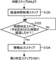
- Any of the driving support methods described above includes an elapsed time acquisition step in which the determination unit acquires the elapsed time since the first current value was determined to be equal to or less than the fourth current value in the third determination step; a time determination step for determining the magnitude of the elapsed time acquired in the time acquisition step and a predetermined time; and if it is determined in the time determination step that the elapsed time is greater than the predetermined time, the control unit , and an information output step of outputting information regarding whether to change the operating conditions of the plurality of electrolyzers.
- the second calculation step is performed when the first current value at the first time is determined to be less than the second current value at the first determination step, and the second current value at the second time is determined to be less than the second current value at the second time. If it is determined that the first current value is larger than the fourth current value, the calculation unit sets the current flowing in the plurality of electrolytic cells in the first time as the second current value, or This may be a step of further calculating the current values to be passed through the plurality of electrolytic cells at predetermined intervals, using the current flowing in the cells as a fourth current value.
- the determination unit determines a first difference between the second current value and the first current value at the first time, and a second difference between the first current value and the fourth current value at the second time. It may further include a fourth determination step of determining the magnitude of the difference. In the second calculation step, when it is determined in the fourth determination step that the first difference is larger than the second difference, the calculation unit sets the current flowing in the plurality of electrolytic cells in the first time as a second current value, and The step may be to further calculate the value at predetermined intervals.
- the calculation unit sets the current flowing through the plurality of electrolytic cells in the second time as a fourth current value, and The step may be to further calculate the value at predetermined intervals.
- the calculation unit performs a fourth calculation in which the calculation unit further calculates the third current value when the one electrolytic cell specified in the electrolytic cell specifying step is stopped at predetermined intervals. step, and a second determination step in which the determination unit determines the magnitude of the third current value and the fourth current value, and in the second determination step, when the third current value is determined to be equal to or less than the fourth current value.
- the control unit may further include a control step of controlling the current flowing through the plurality of electrolytic cells to a third current value.
- any of the driving support methods described above may further include a sixth determination step in which the determination unit determines the magnitude of the third current value and the second current value.
- the control step when the third current value is determined to be less than or equal to the fourth current value in the fifth determination step, and the third current value is determined to be greater than or equal to the second current value in the sixth determination step, the control unit , the step may be a step of controlling the current flowing through the plurality of electrolytic cells to a third current value.
- the specifying unit when the third current value at at least one predetermined time is determined to be less than the second current value in the sixth determining step, the specifying unit: This may be a step of further identifying another electrolytic cell to be stopped among the plurality of electrolytic cells.
- the calculation unit calculates the current value when one electrolytic cell and the other electrolytic cell are stopped at predetermined intervals as a third current value. It may be a step of further calculating.
- the calculation unit calculates the current flowing through the plurality of electrolyzers. This may be a step of further calculating the current value to be caused to flow through the plurality of electrolytic cells at predetermined time intervals, using the second current value as the second current value.
- the second calculation step performs the calculation when it is determined in the fifth determination step that the third current value at at least one predetermined time is larger than the fourth current value.
- the part may be a step of further calculating the current value to be passed through the plurality of electrolytic cells at each predetermined time, with the current flowing in the plurality of electrolytic cells at at least one predetermined time as a fourth current value.
- the determining unit determines whether the concentration of the product in the aqueous solution of the product is greater than a predetermined first concentration, and whether the impurity concentration of the product is less than a predetermined second concentration. It may further include a seventh determination step of determining whether or not.
- the control step when it is determined in the seventh determination step that the concentration of the product is higher than the first concentration and lower than the second concentration, the control unit selects the electrolytic cell to be stopped, which is specified in the electrolytic cell specifying step.
- the step may be a step of controlling the current flowing through the electrolytic cell to be smaller than the current flowing through the other electrolytic cells.
- any of the above driving support methods includes a size determination step in which the determination unit determines the magnitude of the power consumption amount for each predetermined time and the amount of power that can be supplied to the electrolytic cell for each predetermined time. , a surplus power amount calculation step in which the calculation unit calculates a surplus power amount that is a difference between the suppliable power amount and the power consumption amount at a time when the power consumption amount is determined to be less than the suppliable power amount;
- the unit may further include a power control step of controlling the power supplied to the electrolytic cell to include the surplus power at other times when the power consumption is determined to be equal to or greater than the supplyable power.
- a driving assistance program causes the computer to function as a driving support device.
- FIG. 1 is a diagram showing an example of an electrolysis device 200 according to one embodiment of the present invention.
- FIG. 2 is a diagram of the electrolysis device 200 shown in FIG. 1 viewed from the X-axis direction.
- 3 is a diagram showing an example of details of one electrolytic cell 91 in FIG. 2.
- FIG. 4 is an enlarged view of the vicinity of the ion exchange membrane 84 in the electrolytic cell 91 shown in FIG. 3.
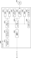
- FIG. 1 is a diagram showing an example of a block diagram of a driving support device 100 according to an embodiment of the present invention.
- FIG. 3 is an image diagram showing an example of driving support for the electrolytic cell 90 by the driving support device 100.
- 5 is a diagram illustrating an example of a display format by a display unit 52.
- FIG. 1 is a diagram showing an example of a display format by a display unit 52.
- FIG. 5 is a diagram illustrating another example of a display form by the display unit 52.
- FIG. It is a figure which shows an example of the relationship between the electrical cost accompanying the operation
- FIG. 5 is a diagram illustrating currents of a plurality of electrolytic cells 90, etc. in calculation of the production amount of product P by the calculation unit 10 (see FIG. 5).
- FIG. 5 is a diagram illustrating another example of a display form by the display unit 52.
- FIG. It is a figure which shows an example of the relationship between the electrical cost accompanying the operation
- FIG. 5 is a diagram illustrating the current of the plurality of electrolytic cells 90 when the plurality of electrolytic cells 90 are integrated into one electrolytic cell 90 in calculating the production amount of the product P by the calculation unit 10 (see FIG. 5). . It is a figure which shows an example of the relationship between the production amount Ac of the product P accompanying the operation
- FIG. 3 is a diagram showing the relationship between the concentration of alkali metal chloride in the liquid 75 (see FIG. 3) and the second current value flowing through the electrolytic cell 90 for a plurality of current efficiencies CE.
- FIG. 5 is a diagram showing an example of the first current value Iv1 for each time T calculated by the calculation unit 10 (see FIG. 5).
- FIG. It is a figure which shows another example of 1st electric current value Iv1 for every time T calculated by the calculation part 10 (refer FIG. 5).
- 13 is a diagram showing an example of the production amount Ac of the product P produced by each of the plurality of electrolytic cells 90 at time T2 (see FIG. 13).
- FIG. 18 is a diagram showing an example of production amount Ac when the operation of electrolytic cell 90-1 is stopped in the example of FIG. 17.
- FIG. 1 is a flowchart illustrating an example of a driving support method according to an embodiment of the present invention.
- FIG. 1 is a flowchart illustrating an example of a driving support method according to an embodiment of the present invention.
- 20 is a flowchart showing an example of details of the stop step S200 in FIG. 19.
- 1 is a flowchart illustrating an example of a driving support method according to an embodiment of the present invention.
- FIG. 3 is a diagram illustrating an example of a computer 2200 in which the driving assistance device 100 according to an embodiment of the present invention may be implemented in whole or in part.
- FIG. 1 is a diagram showing an example of an electrolysis device 200 according to one embodiment of the present invention.
- the electrolysis device 200 is a device that electrolyzes an electrolytic solution.
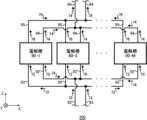
- Electrolyzer 200 includes a plurality of electrolytic cells 90.
- the electrolyzer 200 includes electrolytic cells 90-1 to 90-M (M is an integer of 2 or more).
- the plurality of electrolytic cells 90 operate in parallel.
- the plurality of electrolytic cells 90 operating in parallel refers to the plurality of electrolytic cells 90 electrolyzing the electrolyte solution in parallel.
- the electrolytic cell 90 is a cell that electrolyzes an electrolytic solution.
- the electrolysis device 200 of this example includes an introduction pipe 92, an introduction pipe 93, an outlet pipe 94, and an outlet pipe 95.
- the introduction pipe 92 and the introduction pipe 93 are connected to each of the plurality of electrolytic cells 90.
- the outlet pipe 94 and the outlet pipe 95 are connected to each of the plurality of electrolytic cells 90.
- a liquid 70 and a liquid 72 are introduced into each of the plurality of electrolytic cells 90.
- a liquid 76 and a gas 78 (described later) are led out from each of the plurality of electrolytic cells 90.
- a liquid 74 and a gas 77 (described later) are led out from each of the plurality of electrolytic cells 90.
- the plurality of electrolytic cells 90 are arranged in a predetermined direction.
- the predetermined arrangement direction of the plurality of electrolytic cells 90 is defined as the X-axis direction.
- the direction perpendicular to the X-axis direction and heading from the introduction tube 92 to the outlet tube 94 is defined as the Z-axis.
- the direction perpendicular to the X-axis and perpendicular to the Z-axis direction is referred to as the Y-axis.
- the Z-axis direction may be parallel to the vertical direction, and the XY plane may be a horizontal plane.
- the electrolytic solution electrolyzed in the electrolytic cell 90 is, for example, a NaCl (sodium chloride) aqueous solution or KCl (potassium chloride).
- a NaCl (sodium chloride) aqueous solution or KCl (potassium chloride) is referred to as salt electrolysis.
- the electrolytic cell 90 In the case of salt electrolysis, the electrolytic cell 90 generates Cl 2 (chlorine) by electrolyzing a NaCl (sodium chloride) aqueous solution or KCl (potassium chloride) in an anode chamber 79 (described later), and generates Cl 2 (chlorine) in a cathode chamber 98 (described later).
- Cl 2 chlorine
- H 2 O water
- an aqueous solution of NaOH (sodium hydroxide) or KOH (potassium hydroxide) and H 2 (hydrogen) are generated.
- the electrolytic solution electrolyzed in the electrolytic cell 90 may be a NaOH (sodium hydroxide) aqueous solution or a KOH (potassium hydroxide) aqueous solution.
- the electrolyte is an aqueous NaOH (sodium hydroxide) solution or an aqueous KOH (potassium hydroxide) solution is referred to as alkaline water electrolysis.
- the electrolytic cell 90 generates O 2 (oxygen) and H 2 (hydrogen) by electrolyzing a NaOH (sodium hydroxide) aqueous solution or a KOH (potassium hydroxide) aqueous solution.
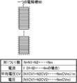
- FIG. 2 is a diagram of the electrolysis device 200 shown in FIG. 1 viewed from the X-axis direction.
- One electrolytic cell 90-M in FIG. 1 will be explained as an example.
- One electrolytic cell 90 may include a plurality of electrolytic cells 91.
- one electrolytic cell 90 includes electrolytic cells 91-1 to 91-N (N is an integer of 2 or more). N is, for example, 50.
- each of electrolytic cells 90-1 to 90-M includes a plurality of electrolytic cells 91.
- the introduction pipe 92 and the introduction pipe 93 are connected to each of the electrolytic cells 91-1 to 91-N.
- the liquid 70 is introduced into each of the electrolytic cells 91-1 to 91-N. After passing through the introduction pipe 92, the liquid 70 may be introduced into each of the electrolytic cells 91-1 to 91-N.
- Liquid 70 is an aqueous solution of alkali metal chloride. Alkali metals are elements belonging to Group 1 of the periodic table of elements.
- the liquid 70 is an aqueous solution of NaCl (sodium chloride) or KCl (potassium chloride).
- the liquid 70 is a NaOH (sodium hydroxide) aqueous solution or a KOH (potassium hydroxide) aqueous solution.
- a liquid 72 is introduced into each of the electrolytic cells 91-1 to 91-N. After passing through the introduction pipe 93, the liquid 72 may be introduced into each of the electrolytic cells 91-1 to 91-N.
- the liquid 72 is an aqueous solution of an alkali metal hydroxide.
- the liquid 72 is an aqueous NaOH (sodium hydroxide) solution.
- the liquid 72 is a NaOH (sodium hydroxide) aqueous solution or a KOH (potassium hydroxide) aqueous solution.
- the outlet pipe 94 and the outlet pipe 95 are connected to each of the electrolytic cells 91-1 to 91-N.
- a liquid 76 and a gas 78 (described later) are led out from each of the electrolytic cells 91-1 to 91-N.
- the liquid 76 and the gas 78 (described later) may be led out of the electrolyzer 200 after passing through the lead-out pipe 95.
- Liquid 76 is an aqueous solution of alkali metal hydroxide.
- the liquid 72 is an aqueous NaOH (sodium hydroxide) solution
- the liquid 76 is an aqueous NaOH (sodium hydroxide) solution.
- the liquid 72 is a KOH (potassium hydroxide) aqueous solution
- the liquid 76 is a KOH (potassium hydroxide) aqueous solution.
- Gas 78 (described below) may be H 2 (hydrogen).
- a liquid 74 and a gas 77 are led out from each of the electrolytic cells 91-1 to 91-N.
- the liquid 74 and the gas 77 may be led out of the electrolyzer 200 after passing through the lead-out pipe 94.
- the liquid 74 is an aqueous solution of an alkali metal chloride.
- liquid 70 is an aqueous solution of NaCl (sodium chloride) or potassium chloride (KCl)
- liquid 74 is an aqueous solution of NaCl (sodium chloride) or KCl (potassium chloride).
- Gas 77 (described below) may be Cl 2 (chlorine).
- the liquid 74 is an aqueous NaOH (sodium hydroxide) solution.
- the liquid 74 is a KOH (potassium hydroxide) aqueous solution.
- the gas 77 (described below) may be O 2 (oxygen).
- FIG. 3 is a diagram showing an example of details of one electrolytic cell 91 in FIG. 2.
- Electrolytic cell 90 has an anode chamber 79, an anode 80, a cathode chamber 98, a cathode 82, and an ion exchange membrane 84.
- one electrolytic cell 91 has an anode chamber 79, an anode 80, a cathode chamber 98, a cathode 82, and an ion exchange membrane 84.
- the anode chamber 79 and the cathode chamber 98 are provided inside the electrolytic cell 91.
- the anode chamber 79 and the cathode chamber 98 are separated by an ion exchange membrane 84.
- An anode 80 is placed in the anode chamber 79 .
- a cathode 82 is arranged in the cathode chamber 98 .
- An inlet pipe 92 and an outlet pipe 94 are connected to the anode chamber 79.
- An inlet pipe 93 and an outlet pipe 95 are connected to the cathode chamber 98 .
- a liquid 70 is introduced into the anode chamber 79 .
- Liquid 72 is introduced into cathode chamber 98 .
- the ion exchange membrane 84 is a membrane-like substance that blocks the passage of ions having the same sign as the ions arranged in the ion exchange membrane 84 and allows the passage of ions of the opposite sign.
- the ion exchange membrane 84 is a membrane that allows Na + (sodium ions) or K + (potassium ions) to pass through and blocks Cl - (chloride ions) from passing through.
- the ion exchange membrane 84 is a membrane that allows Na + (sodium ions) or K + (potassium ions) to pass through and blocks OH - (hydroxide ions) from passing through.
- Anode 80 and cathode 82 may be maintained at predetermined positive and negative potentials, respectively.
- the liquid 70 introduced into the anode chamber 79 and the liquid 72 introduced into the cathode chamber 98 are electrolyzed by the potential difference between the anode 80 and the cathode 82.
- salt electrolysis and alkaline water electrolysis the following chemical reaction occurs at the anode 80.
- [Chemical formula 1-2] Alkaline water electrolysis) 4OH - ⁇ O 2 +2H 2 O+4e -
- NaOH sodium hydroxide
- NaOH sodium hydroxide
- OH - hydrooxide ions
- H 2 O water
- O 2 oxygen
- Gas 77 the O 2 (oxygen) gas
- liquid 74 may be led out from anode chamber 79 .
- Na + (sodium ions) move from the anode chamber 79 to the cathode chamber 98 after passing through the ion exchange membrane 84 due to the attractive force from the cathode 82 .
- the liquid 73 may remain in the anode chamber 79 .
- the liquid 73 is an aqueous solution of an alkali metal chloride.
- liquid 73 is an aqueous NaCl (sodium chloride) solution.
- the Na + (sodium ion) concentration and the Cl ⁇ (chloride ion) concentration of the liquid 73 may be lower than the Na + (sodium ion) concentration and the Cl ⁇ (chloride ion) concentration of the liquid 70, respectively.
- the liquid 73 may be a KCl (potassium chloride) aqueous solution.
- the K + (potassium ion) concentration and the Cl ⁇ (chloride ion) concentration of the liquid 73 may be lower than the K + (potassium ion) concentration and the Cl ⁇ (chloride ion) concentration of the liquid 70, respectively.
- the liquid 73 is a NaOH (sodium hydroxide) aqueous solution or a KOH (potassium hydroxide) aqueous solution.
- a concentration sensor 99 may be provided in the cathode chamber 98. Concentration sensor 99 measures the concentration of alkali metal chloride in liquid 75 .
- the electrolytic cell 90 may be provided with a temperature sensor 97 that measures the temperature of the electrolyte that the electrolytic cell 90 decomposes.
- temperature sensor 97 is provided in cathode chamber 98.
- liquid 72 When the liquid 72 is an aqueous solution of NaOH (sodium hydroxide), NaOH (sodium hydroxide) is ionized into Na + (sodium ions) and OH - (hydroxide ions).
- NaOH sodium hydroxide
- KOH potassium hydroxide
- KOH potassium hydroxide
- K + potassium ion
- OH - hydrooxide ion
- H 2 (hydrogen) gas and OH - (hydroxide ions) are generated by the chemical reaction shown in Chemical Formula 2.
- Gas 78 such as H 2 (hydrogen) gas
- liquid 76 may be led out of cathode chamber 98 .
- the liquid 75 may remain in the cathode chamber 98 .
- the liquid 75 is an aqueous solution of an alkali metal hydroxide.
- the liquid 75 is an aqueous solution of NaOH (sodium hydroxide) or aqueous KOH (potassium hydroxide).
- the cathode chamber 98 contains OH ⁇ (hydroxide ions) generated by the chemical reaction shown in Chemical Formula 2, and Na + (sodium ions) or K + (potassium ions) transferred from the anode chamber 79.
- a liquid 75 in which and is dissolved remains.
- a product produced by the plurality of electrolytic cells 90 is referred to as a product P.
- the product P is NaOH (sodium hydroxide) or Cl2 (chlorine).
- the product P is KOH (potassium hydroxide) or Cl 2 (chlorine).
- the liquids 70 and 72 are NaOH (sodium hydroxide) aqueous solutions (in the case of alkaline water electrolysis)
- the product P is H 2 (hydrogen).
- FIG. 4 is an enlarged view of the vicinity of the ion exchange membrane 84 in the electrolytic cell 91 shown in FIG.
- Anion groups 86 are fixed to the ion exchange membrane 84 of this example. Anions are repelled by the anion groups 86, so they are difficult to pass through the ion exchange membrane 84.
- the anion is Cl ⁇ (chloride ion). Since the cations 71 are not repelled by the anion groups 86, they can pass through the ion exchange membrane 84.
- the liquid 70 (see FIG. 3) is an aqueous NaCl (sodium chloride) solution, the cation 71 is Na + (sodium ion).
- the KCl (potassium chloride) aqueous solution the cation 71 is K + (potassium ion).
- FIG. 5 is a diagram showing an example of a block diagram of the driving support device 100 according to one embodiment of the present invention.
- the operation support device 100 supports the operation of the electrolyzer 200 (see FIG. 2).
- the driving support device 100 includes a calculation section 10, a specification section 20, a determination section 30, and a control section 40.
- the driving support device 100 may include an input section 50, a display section 52, and a storage section 60.
- the driving support device 100 is, for example, a computer including a CPU, a memory, an interface, and the like.
- the control unit 40 may be the CPU.
- the calculation unit 10, the identification unit 20, the determination unit 30, and the control unit 40 may be one CPU.
- a driving support program may be installed in the computer in order to execute a driving support method to be described later, and a driving support program for causing the computer to function as the driving support device 100 may be installed. May be installed.
- the input unit 50 is, for example, a keyboard, a mouse, or the like.
- the display unit 52 is, for example, a display, a monitor, or the like.
- FIG. 6 is an image diagram showing an example of operation support for the electrolytic cell 90 by the operation support device 100.
- the electrolyzer 200 (see FIG. 1) has a terminal 210.
- the terminal 210 is, for example, a distributed control system (DCS).
- the terminal 210 and the driving support device 100 may communicate wirelessly or may communicate by wire.
- the terminal 210 transmits operational data related to the operation of the electrolyzer 200 to the driving support device 100.
- the driving support device 100 transmits instruction data such as the current value to be passed through the electrolytic cell 90 to the terminal 210.
- the display unit 52 displays parameters related to the control of the electrolysis device 200.
- the parameters include, for example, current efficiency CE (described later), voltage CV (described later), and the like.
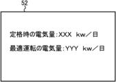
- FIG. 7 is a diagram showing an example of a display format by the display unit 52.
- the display unit 52 displays the amount of electricity at the rated time and the amount of electricity at the optimum operation.
- the display unit 52 may further display power consumption amount Ec (described later) for each time T.
- FIG. 8 is a diagram showing another example of the display form by the display unit 52.
- the operating status of each electrolytic cell 90 is displayed on the display section 52.
- the display unit 52 displays guidance regarding stopping the tank for the user of the driving support device 100.
- the guidance regarding stopping the electrolytic cell 90 is guidance regarding stopping the operation of the electrolytic cell 90.
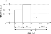
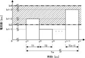
- FIG. 9 is a diagram illustrating an example of the relationship between the electrical cost associated with the operation of a plurality of electrolytic cells 90 operating in parallel and the time t at which the plurality of electrolytic cells 90 operate.
- the electricity cost is referred to as electricity cost Ep.
- Time T is a period between one time t and another time t' after the one time t, during which the plurality of electrolytic cells 90 operate.
- the period of time T may be predetermined.
- the period from time t (1) to time t (2) is time T1
- the period from time t (2) to time t (3) is time T2
- time t (n-1) to Let the period of time t (n) be time T (n-1).
- the electricity cost Ep may be expressed as a monetary amount, may be expressed as the amount of power consumed by the operation of the plurality of electrolytic cells 90 operating in parallel, or may be expressed as an amount in other units.
- the power consumption amount is referred to as power consumption amount Ec.
- the electricity cost Ep may be a value obtained by converting the sum of a plurality of types of costs into a monetary amount.
- FIG. 9 shows an example of the relationship between the power consumption amount Ec and the time t at which the plurality of electrolytic cells 90 operate.
- the electricity cost Ep may vary depending on the time T.
- the electricity cost Ep at time T1 is assumed to be electricity cost Ep2
- the electricity cost Ep at time T2 is assumed to be electricity cost Ep3
- the electricity cost Ep at time T3 is assumed to be electricity cost Ep1.
- the electricity cost Ep1 is smaller than the electricity cost Ep2, and the electricity cost Ep2 is smaller than the electricity cost Ep3.
- the time T1 is, for example, early in the morning.
- Time T2 is, for example, a time during the day.
- Time T3 is, for example, midnight.
- the electricity cost Ep for each time T may be input through the input unit 50.
- FIG. 10 is a diagram showing an example of the power consumption amount Ec and the suppliable power amount Es for each time T.
- the suppliable power amount Es may refer to the maximum value of the power amount that can be supplied to the plurality of electrolytic cells 90 in one time T.
- the supplyable power Es is the maximum amount of power that can be distributed to the electrolyzer 200 when the factory supplies power to multiple devices including the electrolyzer 200. It may be electricity.
- the determination unit 30 may determine the magnitude of the power consumption Ec and the suppliable power amount Es at each time T. In the example of FIG. 10, the determining unit 30 determines that the power consumption amount Ec is less than the suppliable power amount Es at time T1, and the power consumption amount Ec is less than the suppliable power amount Es at time T1 and time T(n-1). It is judged that it exceeds.
- the identifying unit 20 may identify one time T when the power consumption amount Ec is less than the suppliable power amount Es and another time T when the power consumption amount Ec is greater than or equal to the suppliable power amount Es. In the example of FIG. 10, the specifying unit 20 specifies time T1 as one time T, and specifies at least one of time T2 and time T(n-1) as another time T.
- the calculation unit 10 may calculate the surplus power amount, which is the difference between the suppliable power amount Es and the power consumption amount Ec, at one time T.
- the surplus power amount is referred to as surplus power amount Em.
- the calculation unit 10 calculates the surplus power amount Em at time T1.
- the control unit 40 may control the power supplied to the electrolytic cell 90 to include the surplus power Em at other times T when the power consumption Ec is determined to be equal to or greater than the suppliable power amount Es.
- the power including the surplus power amount Em may be the power amount obtained by adding the surplus power amount Em to the suppliable power amount Es.
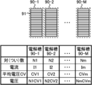
- FIG. 11 is a diagram illustrating the currents of the plurality of electrolytic cells 90, etc. in calculation of the production amount of the product P by the calculation unit 10 (see FIG. 5).
- the number of pairs of electrolytic cells 91 (see FIG. 2) in each of electrolytic cells 90-1 to 90-M is set to N1 to Nm, respectively.
- the number of pairs is the number of pairs of anode chambers 79 and cathode chambers 98 in one electrolytic cell 91.
- the number of pairs in one electrolytic cell 91 is equal to the number of ion exchange membranes 84 (see FIG. 3) in one electrolytic cell 91.
- the currents flowing through each of the electrolytic cells 90-1 to 90-M are defined as current I1 to current Im.
- the voltages of electrolytic cells 90-1 to 90-M are set to voltage CV1 to voltage CVm, respectively. As shown in FIG. 11, the voltages of electrolytic cells 90-1 to 90-M are N1CV1 to NmCVm, respectively.
- FIG. 12 explains the current etc. of the plurality of electrolytic cells 90 when the plurality of electrolytic cells 90 are integrated into one electrolytic cell 90 in calculating the production amount of the product P by the calculation unit 10 (see FIG. 5).
- This is a diagram. Integrating a plurality of electrolytic cells 90 into one electrolytic cell refers to considering a plurality of electrolytic cells 90 as one electrolytic cell 90.
- calculation unit 10 integrates electrolytic cells 90-1 to 90-M into one electrolytic cell 90.
- the number N of pairs in one electrolytic cell 90 is expressed by the following formula (1). That is, the number of pairs N is the sum of the logarithms N1 to Nm.
- the average voltage CV of the electrolytic cells 90 integrated into one electrolytic cell 90 is expressed by the following formula (2). That is, the average voltage CV is expressed as a weighted average of N pairs.
- the target production amount of the product P be the target production amount At.
- the target production amount At is the target production amount of the product P produced by the plurality of electrolytic cells 90 over a predetermined period.
- the predetermined period is referred to as a period Tw.
- the period Tw is the sum of time T1 to time T(n-1).
- period Tw is 24 hours.
- the target production amount At may be input through the input unit 50.
- the calculation unit 10 calculates the production amount of the product P for each time T that satisfies the target production amount At based on the electricity cost Ep or the power consumption Ec for each predetermined time T. .
- the production amount calculated by the calculation unit 10 is defined as production amount Ac.
- the calculation unit 10 calculates the production amount Ac for the electrolytic cells 90 integrated into one electrolytic cell 90 in FIG.
- the calculation unit 10 also calculates first current values Iv1 to fourth current values Iv4, which will be described later, for the electrolytic cells 90 integrated into one electrolytic cell 90 in FIG.
- the specifying unit 20 (see FIG. 5) specifies the operating electrolytic cell 90 among the plurality of electrolytic cells 90 based on the production amount Ac calculated by the calculating unit 10.
- the control unit 40 controls the current flowing through the operating electrolytic cell 90 specified by the specifying unit 20.
- the identification unit 20 may identify the electrolytic cell 90 to be stopped among the plurality of electrolytic cells 90.
- the control unit 40 may control the current flowing through the electrolytic cell 90 that is stopped to be smaller than the current flowing through the electrolytic cell 90 that is not stopped.
- the control unit 40 may set the current flowing through the electrolytic cell 90 to be stopped to zero.
- the calculation unit 10 may calculate the first current value to be passed through the plurality of electrolytic cells 90 for each time T based on the production amount Ac.
- the first current value is referred to as a first current value Iv1.
- the calculation unit 10 may calculate the first current value Iv1 to be passed through the electrolytic cell 90 that is not stopped when the current that is passed through the electrolytic cell 90 that is to be stopped is zero.
- FIG. 13 is a diagram showing an example of the relationship between the production amount Ac of the product P and the time T during which the plurality of electrolytic cells 90 operate in parallel.
- the production amount Ac may vary depending on the time T.
- the production amount Ac at time T1 is set as production amount Ac2
- the production amount Ac at time T2 is set as production amount Ac1
- the production amount Ac at time T(n-1) is set as production amount Ac3.
- the production amount Ac1 is smaller than the production amount Ac2
- the production amount Ac2 is smaller than the production amount Ac3.
- the electricity cost Ep at time T1 is the electricity cost Ep (1)
- the electricity cost Ep at time T2 is the electricity cost Ep (2)
- the electricity cost Ep at time T(n-1) is the electricity cost Let Ep (n-1) .
- the current efficiency of the electrolytic cell 90 is defined as current efficiency CE.
- the current efficiency CE refers to the ratio of the actual production amount to the theoretical production amount of the product P.
- the sum of the production amounts Ac of the product P over the period Tw is defined as the total production amount Acs.
- the total production amount Acs is expressed by the following formula (3).
- the total electricity cost Ep over the period Tw is defined as the total electricity cost Eps.
- the total electricity cost Eps is expressed by the following formula (4).
- the current value I (j) is expressed by the following equation (6).
- the calculation unit 10 may calculate the first current value Iv1 based on the above equation (6).
- the calculation unit 10 may calculate the production amount Ac that satisfies the target production amount At of the product P over the period Tw and minimizes the electricity cost Ep or the power consumption Ec over the period Tw.
- the calculation unit 10 sets the total production amount Acs in equation (3) to the target production amount At, and calculates the production amount Ac that minimizes the total electricity cost Eps in equation (4) based on equations (3) to (6). You can calculate it using
- the specifying unit 20 may specify which electrolytic cell 90 is to be operated among the plurality of electrolytic cells 90 based on the production amount Ac that minimizes the electricity cost Ep.
- FIG. 14 is a diagram showing the relationship between the concentration of alkali metal chloride in the liquid 75 (see FIG. 3) and the second current value flowing through the electrolytic cell 90 for a plurality of current efficiencies CE.
- the second current value is referred to as a second current value Iv2.
- the impurity concentration which is an index of the quality of the product P, be the concentration Cs.
- the concentration Cs may refer to the NaCl (sodium chloride), NaClO 3 (sodium chlorate) concentration or HClO (hypochlorous acid) concentration in the product P.
- the concentration Cs may refer to the O 2 (oxygen) concentration in the product P.
- the concentration Cs may refer to the KCl (potassium chloride) concentration, KClO 3 (potassium chlorate) concentration or KClO (potassium hypochlorite) concentration in the product P .
- the concentration Cs is the concentration of alkali metal chloride in the aqueous solution of product P (liquid 75).
- the concentration Cs may be measured by a concentration sensor 99 (see FIG. 4).
- the identification unit 20 (see FIG. 5) may acquire the concentration Cs measured by the concentration sensor 99.
- the flow rate of the product P (H 2 (hydrogen)) is represented by FL.
- FL is the flow rate of gas 78.
- the flow rate FL may be measured by a flow sensor.
- Am be the theoretical amount of gas 78 generated based on the current I.
- Ls be the theoretical loss amount of the product P (H 2 (hydrogen)) based on the concentration (concentration Cs) of H 2 (hydrogen) in the gas 77 (O 2 (oxygen)).
- Current efficiency CE in the case of alkaline water electrolysis is expressed by the following formula (7-1) or formula (7-2).
- the relationship between the concentration Cs and the current value shown in FIG. 14 may be obtained by measuring the change in the concentration Cs when the current value is changed.
- the concentration Cs tends to decrease as the current value increases.
- the maximum current efficiency CE among the current efficiencies CE1 to CE5 is the current efficiency CE1
- the minimum current efficiency CE is the current efficiency CE5.
- the concentration Cs tends to decrease as the current efficiency CE decreases.
- the second current value Iv2 is a current value for satisfying a predetermined quality of the product P.
- the second current value Iv2 may be the minimum current value to satisfy the quality.
- the relationship between the concentration Cs and the second current value Iv2 shown in FIG. 14 may be obtained in advance.
- the relationship between the concentration Cs and the second current value Iv2 obtained in advance may be stored in the storage unit 60.
- the calculation unit 10 may calculate the second current value Iv2 to be caused to flow through the plurality of electrolytic cells 90 based on the concentration Cs.
- the calculation unit 10 may calculate the second current value Iv2 by fitting the relationship between the concentration Cs and the second current value Iv2 shown in FIG. 14 to the following equation (8).
- F is a constant.
- F is, for example, 10.8.
- At least one of the first current value Iv1 and the second current value Iv2 may be determined based on the temperature of the electrolytic solution.
- the temperature of the electrolyte may be measured by a temperature sensor 97 (see FIG. 3).
- the performance of the electrolytic cell 90 may vary depending on the temperature of the electrolytic solution and at least one of the first current value Iv1 and the second current value Iv2. Therefore, at least one of the first current value Iv1 and the second current value Iv2 may be determined based on the temperature of the electrolytic solution.
- the determination unit 30 may determine the magnitude of the first current value Iv1 and the second current value Iv2 for each time T calculated by the calculation unit 10 (see FIG. 5).
- the determination unit 30 may determine the magnitude of the first current value Iv1 for each time T and a predetermined fourth current value to be passed through the plurality of electrolytic cells 90.
- the fourth current value is referred to as a fourth current value Iv4.
- the fourth current value Iv4 may be the maximum current value that can flow through the plurality of electrolytic cells 90.
- the maximum current value is, for example, 16.2 kA.
- At least one time T from time T1 to time T(n-1) is defined as a first time Ta1, and the at least one time T different from the first time Ta1 is defined as a second time Ta2.
- the identification unit 20 may identify one electrolytic cell 90 to be stopped among the plurality of electrolytic cells 90.
- the one electrolytic cell 90 may be any one electrolytic cell 90 among the plurality of electrolytic cells 90, or may be any two or more electrolytic cells 90.
- the determining unit 30 determines that the first current value Iv1 is may refer to the case where it is determined that the current value Iv4 is equal to or less than the fourth current value Iv4.
- the determination unit 30 determines that the first current value Iv1 is greater than or equal to the second current value Iv2, and determines that the first current value Iv1 is greater than the fourth current value Iv4 at the second time Ta2.
- the specifying unit 20 may specify one electrolytic cell 90 to be stopped among the plurality of electrolytic cells 90.
- the case where the first current value Iv1 is determined by the determining unit 30 to be equal to or higher than the second current value Iv2 means that the first current value Iv1 is determined by the determining unit 30 to be equal to may refer to the case where it is determined that the current value Iv2 is greater than or equal to the second current value Iv2.
- FIG. 15 is a diagram showing an example of the first current value Iv1 for each time T calculated by the calculation unit 10 (see FIG. 5).
- the first current value Iv1 at time T1 is the first current value Iv1-1
- the first current value Iv1 at time T2 is the first current value Iv1-2
- the first current value Iv1 at time T(n-1) is the first current value Iv1-1.
- the current value Iv1 is set as a first current value Iv1-3.
- FIG. 15 also shows the second current value Iv2 and the fourth current value Iv4 described above. In FIG. 15, the range from the second current value Iv2 to the fourth current value Iv4 is indicated by hatching.
- the first current value Iv1-2 and the first current value Iv1-3 are greater than or equal to the second current value Iv2 and less than or equal to the fourth current value Iv4, and the first current value Iv1-1 is less than the second current value Iv2.
- the specifying unit 20 may specify the time T at which the production amount Ac is the smallest. In the example of FIG. 13, the specifying unit 20 specifies time T2 as the time T when the production amount Ac is the smallest. In this example, the first time Ta1 is time T2. In this example, the specifying unit 20 (see FIG. 5) specifies one electrolytic cell 90 to be stopped among the plurality of electrolytic cells 90 at time T2.
- the control unit 40 controls the The current flowing through the tank 90 may be controlled to the first current value Iv1.
- the determination unit 30 may acquire the elapsed time since the first current value Iv1 was determined to be greater than or equal to the second current value Iv2 and less than or equal to the fourth current value.
- the elapsed time is referred to as elapsed time Ts.
- the determination unit 30 may determine the magnitude of the elapsed time Ts and a predetermined time.
- the predetermined time is defined as time Tp.
- the time Tp may be a period from when it is determined whether or not to change the operating conditions of the electrolytic cell 90 to when it is next determined whether or not to change the operating conditions of the electrolytic cell 90.
- the time Tp may be the time Tw shown in FIGS. 13 and 15.
- the operating conditions of the electrolytic cell 90 are defined as operating conditions Cd.
- the operating conditions Cd may include at least one of current efficiency CE, voltage CV, electricity cost Ep, target production amount At, and the length of each time from time T1 to time T(n-1).
- the control unit 40 When the determination unit 30 (see FIG. 5) determines that the elapsed time Ts is greater than the time Tp, the control unit 40 (see FIG. 5) outputs information regarding whether or not to change the operating condition Cd. good.
- the control unit 40 outputting the information may mean that the control unit 40 causes the display unit 52 (see FIG. 5) to display the information.
- FIG. 16 is a diagram showing another example of the first current value Iv1 for each time T calculated by the calculation unit 10 (see FIG. 5).
- the first current value Iv1-3 is larger than the fourth current value Iv4.
- the second time Ta2 is time T(n-1).
- the determining unit 30 determines that the first current value Iv1 is less than the second current value Iv2 at the first time Ta1, and the first current value Iv1 is less than the fourth current value Iv4 at the second time Ta2. If it is determined that the current flowing through the plurality of electrolytic cells 90 is large at the first time Ta1, the calculation unit 10 (see FIG. 5) sets the current flowing through the plurality of electrolytic cells 90 at the first time Ta1 to the second current value Iv2, or sets the current flowing through the plurality of electrolytic cells 90 at the second time Ta2. The current value flowing through the plurality of electrolytic cells 90 may be further calculated for each time T by setting the current flowing through the electrolytic cell 90 as the fourth current value Iv4.
- the difference between the second current value Iv2 and the first current value Iv1 at the first time Ta1 is defined as a first difference df1.
- the first difference df1 is Iv2-Iv1.
- the difference between the first current value Iv1 and the fourth current value Iv4 at the second time Ta is defined as a second difference df2.
- the second difference df2 is Iv1-Iv4.
- the determination unit 30 may determine the magnitude of the first difference df1 at the first time Ta1 and the second difference df2 at the second time Ta2. If the determining unit 30 determines that the first difference df1 is larger than the second difference df2, the calculating unit 10 (see FIG. 5) converts the current flowing through the plurality of electrolytic cells 90 at the first time Ta1 into a second current. The current value may be further calculated at each time T as the value Iv2.
- the calculating unit 10 sets the current flowing through the plurality of electrolytic cells 90 at the second time Ta2 as a fourth current value Iv4, and calculates the current The value may be further calculated at each time T.
- the second difference df2 is larger than the first difference df1. Therefore, the calculation unit 10 further calculates the current value for each time T, with the current flowing through the plurality of electrolytic cells 90 at the second time Ta2 as the fourth current value Iv4.
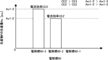
- FIG. 17 is a diagram showing an example of the production amount Ac of the product P produced by each of the plurality of electrolytic cells 90 at time T2 (see FIG. 13).
- the case where the number of the plurality of electrolytic cells 90 shown in FIG. 1 is three (M 3) will be described as an example.
- the current efficiencies CE of the electrolytic cells 90-1 to 90-3 are current efficiencies CE1 to CE3, respectively. It is assumed that current efficiency CE3 is larger than current efficiency CE2, and current efficiency CE2 is larger than current efficiency CE1.
- the production quantities Ac of the electrolytic cells 90-1 to 90-3 are production quantities Ac1-1 to production quantities Ac1-3, respectively. It is assumed that the production amount Ac1-3 is larger than the production amount Ac1-2, and the production amount Ac1-2 is larger than the production amount Ac1-1.
- the identification unit 20 may identify the electrolytic cell 90 with the smallest production amount Ac as the one electrolytic cell 90 to be stopped.
- the specifying unit 20 specifies the electrolytic cell 90-1 to be stopped.
- the identification unit 20 may identify one or more electrolytic cells 90 among the plurality of electrolytic cells 90 as one electrolytic cell 90 to be stopped.
- the identification unit 20 may identify the electrolytic cells 90 to be stopped in descending order of the obtained production amount.
- FIG. 18 is a diagram showing an example of the production amount Ac when the operation of electrolytic cell 90-1 is stopped in the example of FIG. 17.
- the current efficiencies CE of the electrolytic cell 90-2 and the electrolytic cell 90-3 are current efficiency CE2' and current efficiency CE3', respectively.
- the production amount Ac of the electrolytic cell 90-1 and the electrolytic cell 90-2 is a production amount Ac1-2' and a production amount Ac1-3', respectively.
- the calculation unit 10 may further calculate the current value for each time T when the one electrolytic cell 90 specified by the identification unit 20 (see FIG. 5) is stopped. This current value is defined as a third current value Iv3. In this example, the calculation unit 10 further calculates the current value when the operation of the electrolytic cell 90-1 is stopped at each time T.
- the third current value Iv3 may be larger than the first current value Iv1.
- Current efficiency CE2' may be greater than current efficiency CE2 (see FIG. 17).
- Current efficiency CE3' may be greater than current efficiency CE3 (see FIG. 17).
- the production amount Ac1-2' may be larger than the production amount Ac1-2 (see FIG. 17).
- the production amount Ac1-3' may be larger than the production amount Ac1-3 (see FIG. 17).
- the determination unit 30 may determine the magnitude of the third current value Iv3 and the fourth current value Iv4 at each time T.
- the control unit 40 controls the current flowing through the plurality of electrolyzers 90 to the third current value Iv3. It's okay.
- the control unit 40 controls the current flowing through the electrolytic cells 90-2 and 90-3 to the third current Iv3.
- the determination unit 30 may further determine the magnitude relationship between the third current value Iv3 and the second current value Iv2.
- the control unit 40 controls the plurality of electrolytic cells 90.
- the flowing current may be controlled to the third current value Iv3.
- the determining unit 30 determines the magnitude of the third current value Iv3 and the fourth current value Iv4 and the magnitude of the third current value Iv3 and the second current value Iv2 at each time T. good.
- the concentration C ho of the product P is expressed by the following formula (9).
- the concentration Cho is NaOH (sodium hydroxide, so-called caustic soda).
- the concentration Cho is the concentration of KOH (potassium hydroxide).
- V cell is the volume of each pair. In this example, it is assumed that the volume of all pairs is V cell .
- V other is the total volume of each layer such as the subheader and the gas-liquid separation tank.
- Liquid 76 and gas 78 (see FIG. 3) are led from electrolytic cell 90 to the subheader. The liquid 76 and gas 78 led out to the subheader are separated into liquid 76 and gas 78 in the gas-liquid separation tank.
- V tank is the volume of the circulation tank.
- the circulation tank is a tank in which the liquid 76 separated in the above-mentioned gas-liquid separation tank is temporarily stored.
- NC is the number of pairs per one electrolytic cell 90.
- NE is the number of electrolytic cells 90 in the electrolytic device 200.
- NE 1 is the number of electrolytic cells 90 whose operation has been stopped.
- D is the density of the product P (kg/m 3 ).
- t (k) is the waiting time. t (k) may be any time T from time T1 to time T(n-1).
- the concentration Cs (see FIG. 14) is expressed by the following formula (10).
- a predetermined concentration of the product P in the liquid 75 is defined as a first concentration C1.
- the first concentration C1 may be the minimum concentration that guarantees a predetermined quality of the product P.
- the predetermined impurity concentration of the product P be a second concentration C2.
- the second concentration C2 may be the maximum impurity concentration that guarantees a predetermined quality of the product P.
- the determination unit 30 may determine whether the concentration Cho is greater than the first concentration C1.
- the determination unit 30 may determine whether the concentration Cs is less than the second concentration C2.
- the control unit 40 controls the identification unit 20 (see FIG. 5).
- the current flowing through the one electrolytic cell 90 to be stopped which is specified by , may be controlled to be smaller than the current flowing through the other electrolytic cells 90 .
- the liquid 70 and the liquid 72 are stopped.
- the electrolytic cell 90 may be circulated through another electrolytic cell 90.
- the determination unit 30 determines that the concentration Cho is less than or equal to the first concentration C1, or that the concentration Cs is greater than or equal to the second concentration C2, the liquid 73 and the liquid 75 (see FIG. 3) are removed from the stopped electrolysis.
- the tank 90 may be discharged.
- the identification unit 20 determines whether the plurality of electrolytic cells 90 Other electrolytic cells 90 to be stopped may be further specified.
- the other electrolytic cell 90 is a different electrolytic cell 90 from the one electrolytic cell 90 described above.
- the other electrolytic cell 90 may be any one electrolytic cell 90 other than the above-mentioned one electrolytic cell 90 among the plurality of electrolytic cells 90, and may be any two or more electrolytic cells 90. Good too.
- the specifying unit 20 may specify the electrolytic cell 90 with the smallest production amount Ac among the electrolytic cells 90 in operation as other electrolytic cells 90 to be stopped.
- the calculation unit 10 may further calculate the current value when one electrolytic cell 90 and the other electrolytic cell 90 are stopped at each time T as the third current value Iv3.
- the determination unit 30 may determine the magnitude of the third current value Iv3 and the fourth current value Iv4 when one electrolytic cell 90 and the other electrolytic cell 90 are stopped.
- the control unit 40 controls the current flowing through the plurality of electrolytic cells 90 to the third current value Iv3. May be controlled.
- the determination unit 30 may further determine the magnitude of the third current value Iv3 and the second current value Iv2 when one electrolytic cell 90 and the other electrolytic cell 90 are stopped.
- the control unit 40 controls the current flow to the plurality of electrolytic cells 90. The current may be controlled to the third current value Iv3.
- the specifying unit 20 stops.
- the electrolytic cell 90 may be further specified.
- the calculation unit 10 may calculate the current value when the plurality of identified electrolytic cells 90 are stopped.
- the identification unit 20 may further identify the electrolytic cell 90 to be stopped until it is determined that the current value is equal to or higher than the second current value Iv2.
- the calculation section 10 calculates the current flowing through the plurality of electrolytic cells 90 into the first one.
- the current value to be passed through the plurality of electrolytic cells 90 may be further calculated for each time T as the second current value Iv2 or as the fourth current value Iv4.
- the calculation unit 10 may further calculate the current value flowing through the plurality of electrolytic cells 90 at each time T by setting the current flowing in all the electrolytic cells 90 as the second current value Iv2 or as the fourth current value Iv4.
- the calculation unit 10 determines that the third current value Iv3 is larger than the fourth current value Iv4 at at least one time T
- the current flowing through the plurality of electrolytic cells 90 at time T may be set as the fourth current value Iv4, and the current value flowing through the plurality of electrolytic cells 90 may be further calculated for each time T.
- the at least one time T refers to at least one time T from time T1 to time T(n-1) in FIG.
- FIG. 19 is a flowchart illustrating an example of a driving support method according to one embodiment of the present invention.
- An operation support method according to one embodiment of the present invention is an operation support method that supports operation of the electrolytic cell 90 (see FIG. 1).
- the driving support method includes a first calculation step S104 (see FIG. 19).
- the driving support method may include a 0th determination step S100, an electrolytic cell integration step S102, and an input step S88.
- the driving support method includes a second calculation step S106, a third calculation step S108, a first determination step S110, a second determination step S112, a third determination step S114, a control step S116, a fourth determination step S118, and a determination step S94. It's okay.
- the driving support method may include a first current setting step S130, a second current setting step S132, and a third current setting step S136.
- the driving support method may include an elapsed time acquisition step S120, an information output step S124, and a stop step S200.
- the zeroth determination step S100 is a step of determining whether there is a change in the operating condition Cd of the electrolytic cell 90.
- the operating conditions Cd include at least one of current efficiency CE, voltage CV, target production amount At, electricity cost Ep, power consumption Ec, and the length of each time from time T1 to time T(n-1). It's okay.
- the 0th determination step S100 may be a step in which the determination unit 30 (see FIG. 5) determines whether there is a change in the driving condition Cd, and the user of the driving support device 100 determines whether there is a change in the driving condition Cd. It may be a step of determining.
- the driving support method proceeds to input step S88. If it is not determined in the 0th determination step S100 that there is a change in the operating condition Cd, the operation support method proceeds to the electrolytic cell integration step S102.
- the input step S88 is a step of inputting input parameters to the driving support device 100 (see FIG. 5).
- the input step S88 may be a step in which the user of the driving support device 100 inputs the driving condition Cd through the input unit 50 (see FIG. 5).
- the electrolytic cell integration step S102 is a step in which the calculation unit 10 (see FIG. 5) integrates a plurality of electrolytic cells 90 into one electrolytic cell 90 (see FIGS. 11 and 12) in calculating the production amount of the product P. It is. In this example, the calculation unit 10 integrates the electrolytic cells 90-1 to 90-M into one electrolytic cell 90.
- the first calculation step S104 may include a zeroth calculation step S90 and a determination step S92.
- the calculation unit 10 calculates the product P for each predetermined time T when the fourth current value Iv4 is passed through the plurality of electrolytic cells 90 operating in parallel. This is a step of calculating the production amount Ac.
- the 0th calculation step S90 may be a step in which the calculation unit 10 calculates the production amount Ac for each time T when the fourth current value Iv4 is passed through all the electrolytic cells 90 operating in parallel.
- Determination step S92 is a step in which the determination unit 30 (see FIG. 5) determines whether the production amount Ac satisfies the target production amount At.
- the driving support method proceeds to the second calculation step S106. If it is not determined in the determination step S92 that the production amount Ac satisfies the target production amount At, the driving support method returns to the input step S88.
- the calculation unit 10 in the first calculation step S104, the calculation unit 10 (see FIG. 5) satisfies the target production amount At over the period Tw (see FIGS. 9 and 13), and minimizes the electricity cost Ep or the power consumption Ec over the period Tw. This may be a step of calculating the production amount P to be made.
- the second calculation step S106 is a step in which the calculation unit 10 (see FIG. 5) calculates the first current value Iv1 to be passed through the plurality of electrolytic cells 90 for each time T based on the production amount Ac of the product P.
- the calculation unit 10 calculates the second This is a step of calculating the current value Iv2.
- the second current value Iv2 may be a minimum current value for satisfying a predetermined quality of the product P.
- the determination unit 30 determines the first current value Iv1 for each time T calculated in the second calculation step S106 and the second current value calculated in the third calculation step S108. This is a step of determining the magnitude with respect to Iv2. If it is determined in the first determination step S110 that the first current value Iv1 at the first time Ta1 is less than the second current value Iv2, the driving support method proceeds to the second determination step S112. As described above, the first time Ta1 is at least one time T from time T1 to time T(n-1) (see FIG. 9 and FIG. 13). If it is determined in the first determination step S110 that the first current value Iv1 is greater than or equal to the second current value Iv2, the driving support method proceeds to a third determination step S114.
- the second determination step S112 is a step in which the determination unit 30 (see FIG. 5) determines the magnitude of the first current value Iv1 for each time T calculated in the second calculation step S106 and the fourth current value Iv4. be. If it is determined in the second determination step S112 that the first current value Iv1 is equal to or less than the fourth current value Iv4, the driving support method proceeds to a stop step S200. If it is determined in the second determination step S112 that the first current value Iv1 is larger than the fourth current value Iv4, the driving support method proceeds to a fourth determination step S118.
- the third determination step S114 is a step in which the determination unit 30 (see FIG. 5) determines the magnitude of the first current value Iv1 for each time T calculated in the second calculation step S106 and the fourth current value Iv4. be. If it is determined in the third determination step S114 that the first current value Iv1 is equal to or less than the fourth current value Iv4, the driving support method proceeds to control step S116. If it is determined in the third determination step S114 that the first current value Iv1 is larger than the fourth current value Iv4, the driving support method proceeds to a third current setting step S136.
- the step may be a step in which the control unit 40 (see FIG. 5) controls the current flowing through the plurality of electrolytic cells 90 to the first current value Iv1.
- Determination step S94 is a step of determining whether to stop the operation of electrolyzer 200.
- the determination step S94 may be a step in which the determination unit 30 (see FIG. 5) determines whether to stop the operation of the electrolyzer 200, and the user of the driving support device 100 determines whether to stop the operation of the electrolyzer 200. It may also be a step of determining.
- the operation support method ends the operation support of the electrolyzer 90. If it is not determined in the determination step S94 that the operation of the electrolyzer 200 is to be stopped, the operation support method proceeds to the elapsed time acquisition step S120.
- the first current value Iv1 at the first time Ta1 is determined to be less than the second current value Iv2 at the first determination step S110, and the first current value Iv1 at the second time Ta2 is determined at the second determination step S112.
- the calculation unit 10 sets the current flowing through the plurality of electrolytic cells 90 at the first time Ta1 as the second current value Iv2.
- it may be a step of further calculating the current value flowing through the plurality of electrolytic cells 90 at each time T by setting the current flowing in the plurality of electrolytic cells 90 at the second time Ta2 as the fourth current value Iv4.
- the determination unit 30 determines the first difference df1 (see FIG. 16) between the second current value Iv2 and the first current value Iv1 at the first time Ta1 and the second time Ta2. This is a step of determining the magnitude of the second difference df2 (see FIG. 16) between the first current value Iv1 and the fourth current value Iv4. If it is determined in the fourth determination step S118 that the first difference df1 is larger than the second difference df2, the driving support method proceeds to the first current setting step S130. If it is determined in the fourth determination step S118 that the second difference df2 is larger than the first difference df1, the driving support method proceeds to a second current setting step S132.
- the first current setting step S130 is a step in which the current flowing through the plurality of electrolytic cells 90 at the first time Ta1 (see FIG. 16) is set to the second current value Iv2.
- the second current setting step S132 is a step of setting the current flowing through the plurality of electrolytic cells 90 at the fourth current value Iv4 at the second time Ta2 (see FIG. 16).
- the calculation unit 10 calculates the current value set in the first current setting step S130 or the current value set in the second current setting step S132. This is a step in which the value of the current flowing through the electrolytic cell 90 is further calculated for each time T.
- the third current setting step S136 is a step in which the current flowing through the plurality of electrolytic cells 90 at the second time Ta2 (see FIG. 16) is set to the fourth current value Iv4.
- the calculation unit 10 in the second calculation step S106, further calculates the current value to be passed through the plurality of electrolytic cells 90 at each time T using the current value set in the third current setting step S136. This is the step of calculating.
- FIG. 20 is a flowchart illustrating an example of a driving support method according to an embodiment of the present invention.
- the driving support method may include an elapsed time acquisition step S120, a time determination step S122, and an information output step S124.
- the time determination step S122 is a step of determining the magnitude of the elapsed time Ts acquired in the elapsed time acquisition step S120 and a predetermined time Tp.
- the time Tp may be a period from when it is determined whether or not to change the operating conditions of the electrolytic cell 90 to when it is next determined whether or not to change the operating conditions of the electrolytic cell 90.
- the time Tp may be the time Tw shown in FIGS.
- time determination step S122 determines whether elapsed time Ts is greater than time Tp. If it is determined in time determination step S122 that elapsed time Ts is greater than time Tp, the driving support method proceeds to information output step S124. If it is determined in the time determination step S122 that the elapsed time Ts is smaller than the time Tp, the determination unit 30 continues to determine the magnitude of the elapsed time Ts and the time Tp until it is determined that the elapsed time Ts is greater than the time Tp. continue.
- Information output step S124 is a step in which the control unit 40 (see FIG. 5) outputs information regarding whether to change the operating conditions Cd of the plurality of electrolytic cells 90.
- the control unit 40 outputting the information may mean that the control unit 40 causes the display unit 52 (see FIG. 5) to display the information.
- the driving support method returns to the 0th determination step S100.
- FIG. 21 is a flowchart showing an example of details of the stop step S200 in FIG. 19.
- the driving support method includes an electrolytic cell specifying step S212.
- the driving support method may include a fourth calculation step S214, a fifth determination step S216, a sixth determination step S218, and a seventh determination step S220.
- the driving support method may include a time determination step S210, a determination step S226, a standby circulation step S222, and a discharge step S224.
- the time specifying step S210 is a step in which the specifying unit 20 (see FIG. 5) specifies the time T at which the production amount Ac is the smallest (see FIG. 15).
- the specifying unit 20 selects the operating electrolytic cell 90 from among the plurality of electrolytic cells 90 based on the production amount Ac calculated in the first calculation step S104 (see FIG. 19).
- This step is to identify the In the electrolytic cell specifying step S212, when the first current value Iv1 is determined to be equal to or lower than the fourth current value Iv4 in the second determining step S112, the specifying unit 20 selects one electrolytic cell to be stopped among the plurality of electrolytic cells 90. This may be a step of identifying 90.
- the identification unit 20 may also be a step of specifying one electrolytic cell 90 to be stopped among the plurality of electrolytic cells 90 .
- the electrolytic cell specifying step S212 may be a step of specifying the electrolytic cell 90 to be stopped among the plurality of electrolytic cells 90 at the time T specified in the time specifying step S210.
- the calculation unit 10 (see FIG. 5) further calculates, at each time T, the third current value Iv3 when the one electrolytic cell 90 specified in the electrolytic cell specifying step 212 is stopped.
- This step is to
- the fifth determination step S216 is a step in which the determination unit 30 (see FIG. 5) determines the magnitude of the third current value Iv3 and the fourth current value Iv4.
- the driving support method proceeds to the sixth determination step S218. If it is determined in the fifth determination step S216 that the third current value Iv3 is larger than the fourth current value Iv4, the driving support method proceeds to a fourth current setting step S137 (see FIG. 19).
- the plurality of electrolytic cells 90 are This is a step of setting the flowing current to a fourth current value Iv4.
- the driving support method returns to the second calculation step S106 (see FIG. 19).
- the calculation unit 10 calculates the current flowing through the plurality of electrolytic cells 90 at at least one time T when it is determined that the third current value Iv3 is larger than the fourth current value Iv4. This is a step of further calculating the current value to be passed through the plurality of electrolytic cells 90 for each time T, with the fourth current value Iv4 being set as the fourth current value Iv4.
- the sixth determination step S218 is a step in which the determination unit 30 (see FIG. 5) determines the magnitude of the third current value Iv3 and the second current value Iv2. If it is determined in the sixth determination step S218 that the third current value Iv3 is greater than or equal to the second current value Iv2, the driving support method proceeds to a seventh determination step S220. If it is determined in the sixth determination step S218 that the third current value Iv3 is less than the second current value Iv2, the driving support method proceeds to determination step S226.
- Determination step S226 is a step in which the determination unit 30 (see FIG. 5) determines whether all of the plurality of electrolytic cells 90 have been identified as the electrolytic cells 90 to be stopped. If it is determined in the determination step S226 that all of the plurality of electrolytic cells 90 are not identified as the electrolytic cells 90 to be stopped, the operation support method returns to the electrolytic cell identification step S212. If it is determined in the determination step S226 that all of the plurality of electrolytic cells 90 have been identified as the electrolytic cells 90 to be stopped, the driving support method proceeds to the fifth current setting step S138.
- the identification unit 20 when it is determined in the sixth determination step 218 that the third current value Iv3 at at least one time T is less than the second current value Iv2, the identification unit 20 (see FIG. 5) This may be a step of further specifying another electrolytic cell 90 to be stopped among the electrolytic cells 90.
- the electrolyzer specifying step S212 is performed when the third current value Iv3 at at least one time T is determined to be less than the second current value Iv2 in the sixth determination step 218, and in the determination step S226, a plurality of electrolytic cells
- the identification unit 20 further specifies another electrolytic cell 90 to be stopped among the plurality of electrolytic cells 90 when it is determined that all of the electrolytic cells 90 are not specified as the electrolytic cells 90 to be stopped.
- the other electrolytic cell 90 is a different electrolytic cell 90 from the one electrolytic cell 90 described above.
- the other electrolytic cell 90 may be any one electrolytic cell 90 other than the above-mentioned one electrolytic cell 90 among the plurality of electrolytic cells 90, and may be any two or more electrolytic cells 90. Good too.
- the specifying unit 20 may specify the electrolytic cell 90 with the smallest production amount Ac among the electrolytic cells 90 in operation as other electrolytic cells 90 to be stopped.
- the calculation unit 10 further calculates the current value when one electrolytic cell 90 and the other electrolytic cell 90 are stopped at each time T as a third current value Iv3. It may be a step to In the fifth determination step S216, the determination unit 30 (see FIG. 5) determines the magnitude of the third current value Iv3 and the fourth current value Iv4 when one electrolytic cell 90 and the other electrolytic cell 90 are stopped. It may be a step of determining.
- the sixth determination step S218 is a step in which the determination unit 30 further determines the magnitude of the third current value Iv3 and the second current value Iv2 when one electrolytic cell 90 and the other electrolytic cell 90 are stopped. It's okay.
- the electrolytic cell specifying step S212 is performed when the third current value Iv3 is determined to be less than the second current value Iv2 when the one electrolytic cell 90 and the other electrolytic cell 90 are stopped in the sixth judgment step S218, and the judgment step In S226, if it is determined that all of the plurality of electrolytic cells 90 are not specified as the electrolytic cells 90 to be stopped, the identifying unit 20 may further specify the electrolytic cells 90 to be stopped.
- the electrolytic cell specifying step S212 may be a step of specifying the electrolytic cell 90 to be stopped until the third current value Iv3 is determined to be equal to or greater than the second current value Iv2 in the sixth determination step S218.
- the fifth current setting step S138 is a step of setting the current flowing through the plurality of electrolytic cells 90 to the second current value Iv2.
- the fifth current setting step S138 sets the current flowing through the plurality of electrolytic cells 90 at another time T when the third current value Iv3 is determined to be less than the second current value Iv in the sixth determination step S218. This may be a step of setting the second current value Iv2.
- the driving support method returns to the second calculation step S106 (see FIG. 19).
- the calculation unit 10 see FIG.
- the driving support method After the fifth current setting step S138, the driving support method returns to the second calculation step S106 (see FIG. 19).
- the determination unit 30 determines whether the concentration Cho is greater than the predetermined first concentration C1 of the product P, and whether the concentration Cs is greater than the predetermined first concentration C1 of the product P. This is a step of determining whether the second concentration is less than C2.
- the first concentration C1 may be the minimum concentration that guarantees a predetermined quality of the product P.
- the second concentration C2 may be the maximum impurity concentration that guarantees a predetermined quality of the product P.
- the driving support method proceeds to a standby circulation step S222. If it is determined in the seventh determination step S220 that the concentration C ho is greater than the first concentration C1 and the concentration Cs is not determined to be less than the second concentration C2, the driving support method proceeds to discharge step S224.
- the standby circulation step S222 in a state where the electrolytic cell 90 specified as the electrolytic cell 90 to be stopped in the electrolytic cell specifying step S212 is stopped, the liquid 70 and the liquid 72 (see FIGS. 1 to 3) are This is a step of circulating the electrolytic cell 90.
- the discharge step S224 is a step of discharging the liquid 73 and the liquid 75 (see FIG. 3) from the stopped electrolytic cell 90.
- control unit 40 controls the electrolytic In the control step 112, which is a step of controlling the current flowing in the electrolytic cell 90 to be stopped, which is specified in the cell specifying step S212, to be smaller than the current flowing in the other electrolytic cells 90, the control unit 40 controls the electrolytic cell to be stopped.
- the step may be to control the current flowing through 90 to zero.
- the control unit 40 controls the current flowing through the plurality of electrolytic cells 90 to the third current value Iv3.
- This may be a step of controlling the current value to Iv3.
- the third current value Iv3 is determined to be equal to or less than the fourth current value in the fifth determination step S216, and the third current value Iv3 is determined to be equal to or greater than the second current value Iv2 in the sixth determination step S218.
- the step may be one in which the control unit 40 controls the current flowing through the plurality of electrolytic cells 90 to a third current value Iv3.
- FIG. 22 is a flowchart illustrating an example of a driving support method according to one embodiment of the present invention.
- the driving support method may include a magnitude determining step S302, a first time specifying step S304, a second time specifying step S306, a surplus power amount calculation step S308, and a power control step S310.
- the magnitude determination step S302 is a step in which the determination unit 30 determines the magnitude of the power consumption Ec and the suppliable power amount Es.
- the determination unit 30 may determine the magnitude of the power consumption Ec and the suppliable power amount Es at each time T.
- the power consumption amount Ec for each time T is This is a step in which the specifying unit 20 specifies a time T that is less than the suppliable power amount Es.
- the power consumption amount Ec for each time T is This is a step in which the identifying unit 20 identifies another time T that is equal to or greater than the suppliable power amount Es.
- the surplus power amount calculation step S308 is a step in which the calculation unit 10 calculates the surplus power amount Em, which is the difference between the suppliable power amount Es and the power consumption amount Ec, at one time T.
- the control unit 40 controls the power supplied to the electrolytic cell 90 to include the surplus power Em at other times T when the power consumption Ec is determined to be equal to or greater than the suppliable power Es. This step is to
- a block may represent (1) a stage in a process in which an operation is performed or (2) a section of equipment responsible for performing the operation.
- Certain steps may be performed by dedicated circuits, programmable circuits or processors. Certain sections may be implemented by special purpose circuits, programmable circuits or processors. The programmable circuit and the processor may be supplied with computer readable instructions. The computer readable instructions may be stored on a computer readable medium.
- the dedicated circuit may include at least one of a digital hardware circuit and an analog hardware circuit.
- Dedicated circuitry may include at least one of integrated circuits (ICs) and discrete circuits.
- Programmable circuits may include hardware circuits for logical AND, logical OR, logical XOR, logical NAND, logical NOR, or other logical operations.
- Programmable circuits may include reconfigurable hardware circuits, including flip-flops, registers, memory elements such as field programmable gate arrays (FPGAs), programmable logic arrays (PLAs), and the like.
- the computer-readable medium may include any tangible device capable of storing instructions for execution by a suitable device.
- the computer-readable medium includes the tangible device so that the computer-readable medium has instructions stored on the device that can be executed to create a means for performing the operations specified in the flowchart or block diagram.
- the product will include:
- the computer readable medium may be, for example, an electronic storage medium, a magnetic storage medium, an optical storage medium, an electromagnetic storage medium, a semiconductor storage medium, etc.
- the computer readable medium is more specifically, for example, a floppy disk, diskette, hard disk, random access memory (RAM), read only memory (ROM), erasable programmable read only memory (EPROM or flash memory), Electrically Erasable Programmable Read Only Memory (EEPROM), Static Random Access Memory (SRAM), Compact Disc Read Only Memory (CD-ROM), Digital Versatile Disk (DVD), Blu-ray (RTM) Disc, Memory Stick, Integrated It may be a circuit card or the like.
- Computer-readable instructions may include any of assembler instructions, instruction set architecture (ISA) instructions, machine instructions, machine-dependent instructions, microcode, firmware instructions, state configuration data, source code, and object code.
- the source code and the object code may be written in any combination of one or more programming languages, including object-oriented programming languages and traditional procedural programming languages.
- the object-oriented programming language may be, for example, Smalltalk, JAVA, C++, or the like.
- the procedural programming language may be, for example, the "C" programming language.
- Computer-readable instructions may be implemented on a processor or programmable circuit of a general purpose computer, special purpose computer, or other programmable data processing device, either locally or over a wide area network (WAN), such as a local area network (LAN), the Internet, etc. ).
- a processor or programmable circuit of a general purpose computer, special purpose computer, or other programmable data processing device performs the operations specified in the flowcharts shown in FIGS. 19-22 or the block diagram shown in FIG.
- Computer readable instructions may be executed to create a means for doing so.
- the processor may be, for example, a computer processor, a processing unit, a microprocessor, a digital signal processor, a controller, a microcontroller, or the like.
- FIG. 23 is a diagram illustrating an example of a computer 2200 in which the driving support device 100 according to the embodiment of the present invention may be implemented in whole or in part.
- the program installed on the computer 2200 can cause the computer 2200 to function as one or more sections of the operation or driving support device 100 associated with the operation or driving support device 100 according to the embodiment of the present invention.
- the one or more sections may be executed, or the computer 2200 may be caused to execute each step (see FIGS. 19-22) of the driving assistance method of the present invention.
- the program may cause computer 2200 to perform certain operations associated with some or all of the blocks in the flowcharts (FIGS. 19-22) and block diagrams (FIG. 5) described herein. , may be executed by the CPU 2212.
- the computer 2200 includes a CPU 2212, a RAM 2214, a graphics controller 2216, and a display device 2218.
- CPU 2212, RAM 2214, graphics controller 2216, and display device 2218 are interconnected by host controller 2210.
- Computer 2200 further includes input/output units such as a communication interface 2222, a hard disk drive 2224, a DVD-ROM drive 2226, and an IC card drive.
- the communication interface 2222, hard disk drive 2224, DVD-ROM drive 2226, IC card drive, etc. are connected to the host controller 2210 via the input/output controller 2220.
- the computer further includes legacy input/output units such as ROM 2230 and keyboard 2242. ROM 2230, keyboard 2242, etc. are connected to input/output controller 2220 via input/output chip 2240.
- the CPU 2212 controls each unit by operating according to programs stored in the ROM 2230 and RAM 2214.
- Graphics controller 2216 obtains image data generated by CPU 2212 into a frame buffer or the like provided in RAM 2214 so that the image data is displayed on display device 2218 .
- Hard disk drive 2224 stores programs and data used by CPU 2212 within computer 2200.
- DVD-ROM drive 2226 reads a program or data from DVD-ROM 2201 and provides the read program or data to hard disk drive 2224 via RAM 2214.
- An IC card drive reads programs and data from an IC card or writes programs and data to an IC card.
- the ROM 2230 stores a boot program executed by the computer 2200 upon activation, or a program dependent on the hardware of the computer 2200.
- Input/output chip 2240 may connect various input/output units to input/output controller 2220 via parallel ports, serial ports, keyboard ports, mouse ports, etc.
- a program is provided by a computer readable medium such as a DVD-ROM 2201 or an IC card.
- the program is read from a computer readable medium, installed on hard disk drive 2224, RAM 2214, or ROM 2230, which are also examples of computer readable media, and executed by CPU 2212.
- the information processing described in these programs is read by the computer 2200 and provides coordination between the programs and the various types of hardware resources described above.
- An apparatus or method may be configured according to the use of computer 2200 to effectuate manipulation or processing of information.
- the CPU 2212 executes a communication program loaded into the RAM 2214 and sends communication processing to the communication interface 2222 based on the processing written in the communication program. You may give orders.
- the communication interface 2222 reads transmission data stored in a transmission buffer processing area provided in a recording medium such as a RAM 2214, a hard disk drive 2224, a DVD-ROM 2201, or an IC card under the control of the CPU 2212, and reads the transmission data that has been read. is transmitted to the network, or the received data received from the network is written to a receive buffer processing area provided on the recording medium.
- the CPU 2212 may cause the RAM 2214 to read all or a necessary portion of a file or database stored in an external recording medium such as a hard disk drive 2224, DVD-ROM drive 2226 (DVD-ROM 2201), IC card, etc.
- CPU 2212 may perform various types of processing on data on RAM 2214.
- CPU 2212 may then write back the processed data to an external storage medium.
- CPU 2212 performs various types of operations, information processing, conditional determination, conditional branching, unconditional branching, information retrieval, or Various types of processing may be performed, including substitutions and the like.
- the CPU 2212 may write back the results to the RAM 2214.
- the CPU 2212 may search for information in a file in a recording medium, a database, etc. For example, if a plurality of entries are stored in the recording medium, each having an attribute value of a first attribute associated with an attribute value of a second attribute, the CPU 2212 search for an entry that matches the condition from among the plurality of entries, read the attribute value of the second attribute stored in the entry, and read the second attribute value to meet the predetermined condition. You may obtain the attribute value of the second attribute associated with the first attribute that satisfies.
- the programs or software modules described above may be stored on computer 2200 or in a computer readable medium of computer 2200.
- a storage medium such as a hard disk or RAM provided in a server system connected to a private communication network or the Internet can be used as the computer-readable medium.
- the program may be provided to the computer 2200 by the recording medium.
- Electrolytic cell 92...Introduction tube, 93...Introduction tube, 94...Outlet tube, 95...Outlet tube, 97...Temperature sensor, 98...Cathode chamber, 99...Concentration Sensor, 100... Driving support device, 200... Electrolyzer, 210... Terminal, 2200... Computer, 2201... DVD-ROM, 2210... Host controller, 2212... CPU, 2214... RAM, 2216... Graphic controller, 2218... Display device, 2220... Input/output controller, 2222... Communication interface, 2224... Hard disk drive, 2226... DVD-ROM drive , 2230...ROM, 2240...I/O chip, 2242...Keyboard
Abstract
Provided is an operation support device comprising: a calculation unit that calculates the production amount of products per hour, which satisfies the target production amount of products to be produced over a predetermined period of time by a plurality of electrolyzers, on the basis of predetermined hourly electricity costs or power consumption in the course of the operation of the plurality electrolyzers operating in parallel; and an identification section that identifies an operating electrolyzer among the plurality of electrolyzers on the basis of the production amount calculated by the calculation unit. The calculation unit may calculate a production amount that satisfies a target production amount of products over a period of time and minimizes electricity cost or power consumption over a period of time.
Description
本発明は、運転支援装置、運転支援方法および運転支援プログラムに関する。
The present invention relates to a driving support device, a driving support method, and a driving support program.
特許文献1には、「一定期間における電解装置の生成物の生成量を低減させずに、生成物の製造コストを低減させる。」と記載されている(要約書)。
[先行技術文献]
[特許文献]
[特許文献1] 国際公開第2019/059321号Patent Document 1 states (abstract) that "the manufacturing cost of the product is reduced without reducing the amount of product produced by the electrolytic device in a certain period of time."
[Prior art documents]
[Patent document]
[Patent Document 1] International Publication No. 2019/059321
[先行技術文献]
[特許文献]
[特許文献1] 国際公開第2019/059321号
[Prior art documents]
[Patent document]
[Patent Document 1] International Publication No. 2019/059321
電解槽により生産される生産物の生産量は、電解槽の性能に依存し得る。電解槽の性能は、電解槽の動作時間に伴い低下し得る。並列に動作する複数の電解槽が生産物を生産する場合、複数の電解槽のそれぞれにより生産される生産物の生産量は、電解槽ごとに異なり得る。性能が低下した電解槽により消費される電力は、当該電解槽よりも性能が低下していない電解槽により消費される電力よりも大きくなりやすい。このため、複数の電解槽を備える電解装置においては、複数の電解槽により生産される生産物の総量が目標生産量を満たしつつ、複数の電解槽により消費される電力を抑制することが望ましい。
The amount of product produced by an electrolytic cell may depend on the performance of the electrolytic cell. The performance of an electrolytic cell may decrease with the operating time of the electrolytic cell. When a plurality of electrolytic cells operating in parallel produce a product, the amount of product produced by each of the plurality of electrolytic cells may differ from one electrolytic cell to the next. The power consumed by an electrolytic cell whose performance has deteriorated is likely to be greater than the power consumed by an electrolytic cell whose performance has not deteriorated. For this reason, in an electrolyzer including a plurality of electrolytic cells, it is desirable to suppress the power consumed by the plurality of electrolytic cells while the total amount of products produced by the plurality of electrolytic cells satisfies the target production amount.
本発明の第1の態様においては、運転支援装置を提供する。運転支援装置は、並列に動作する複数の電解槽の動作に伴う、予め定められた時間ごとの電気コストまたは電力消費量に基づいて、複数の電解槽により予め定められた期間にわたり生産される生産物の目標生産量を満たす、予め定められた時間ごとの生産物の生産量を算出する算出部と、算出部により算出された生産量に基づいて、複数の電解槽のうち動作する電解槽を特定する特定部とを備える運転支援装置。
In a first aspect of the present invention, a driving support device is provided. The operation support device is a production system that is produced by multiple electrolytic cells over a predetermined period of time based on the electricity cost or power consumption per predetermined time associated with the operation of multiple electrolytic cells that operate in parallel. A calculation unit that calculates the production amount of a product for each predetermined time that satisfies the target production amount of the product, and a calculation unit that selects an operating electrolytic cell from among the plurality of electrolytic cells based on the production amount calculated by the calculation unit. A driving support device including a specifying unit.
算出部は、予め定められた期間にわたる生産物の目標生産量を満たし、且つ、予め定められた期間にわたる電気コストまたは電力消費量を最小にする、生産量を算出してよい。
The calculation unit may calculate a production amount that satisfies a target production amount of the product over a predetermined period and minimizes electricity cost or power consumption over the predetermined period.
上記いずれかの運転支援装置は、判定部をさらに備えてよい。算出部は、生産物の生産量に基づいて、複数の電解槽に流す第1電流値を予め定められた時間ごとに算出してよい。算出部は、生産物の不純物濃度、または、電解槽が分解する電解液の温度に基づいて、複数の電解槽に流す第2電流値を算出してよい。判定部は、算出部により算出された予め定められた時間ごとの第1電流値と第2電流値との大小を判定し、予め定められた時間ごとの第1電流値と、複数の電解槽に流す予め定められた第4電流値との大小を判定してよい。判定部により、第1電流値が第4電流値以下と判定され、且つ、少なくとも一つの予め定められた時間である第1時間において第1電流値が第2電流値未満と判定された場合、または、第1電流値が第2電流値以上と判定され、且つ、少なくとも一つの予め定められた時間である第2時間において第1電流値が第4電流値よりも大きいと判定された場合、特定部は、複数の電解槽のうち停止する電解槽を特定してよい。
Any of the above driving support devices may further include a determination unit. The calculation unit may calculate the first current value to be passed through the plurality of electrolytic cells at every predetermined time based on the production amount of the product. The calculation unit may calculate the second current value to be passed through the plurality of electrolytic cells based on the impurity concentration of the product or the temperature of the electrolytic solution that the electrolytic cells decompose. The determination unit determines the magnitude of the first current value and the second current value at each predetermined time calculated by the calculation unit, and determines the magnitude of the first current value at each predetermined time and the plurality of electrolytic cells. It may be determined whether the current value is greater than or equal to a predetermined fourth current value. When the determination unit determines that the first current value is less than or equal to the fourth current value, and the first current value is determined to be less than the second current value in at least one predetermined time, the first time, Alternatively, when it is determined that the first current value is greater than or equal to the second current value, and the first current value is determined to be greater than the fourth current value at a second time that is at least one predetermined time, The identification unit may identify an electrolytic cell to be stopped among the plurality of electrolytic cells.
本発明の第2の態様においては、運転支援装置を提供する。運転支援装置は、並列に動作する複数の電解槽の動作に伴う、予め定められた時間ごとの電力消費量に基づいて、複数の電解槽により予め定められた期間にわたり生産される生産物の目標生産量を満たす、予め定められた時間ごとの生産物の生産量を算出し、算出した生産量に基づいて複数の電解槽に流す第1電流値を予め定められた時間ごとに算出し、生産物の不純物濃度、または、電解槽が分解する電解液の温度に基づいて複数の電解槽に流す第2電流値を算出する算出部と、算出部により算出された予め定められた時間ごとの第1電流値と第2電流値との大小を判定し、予め定められた時間ごとの第1電流値と、複数の電解槽に流す予め定められた第4電流値との大小を判定する判定部と、判定部により、第1電流値が第4電流値以下と判定され、且つ、少なくとも一つの予め定められた時間である第1時間において第1電流値が第2電流値未満と判定された場合、または、第1電流値が第2電流値以上と判定され、且つ、少なくとも一つの予め定められた時間である第2時間において第1電流値が第4電流値よりも大きいと判定された場合、複数の電解槽のうち停止する電解槽を特定する特定部とを備える。
In a second aspect of the present invention, a driving support device is provided. The operation support device determines the target amount of products produced by multiple electrolytic cells over a predetermined period of time based on the power consumption per predetermined time associated with the operation of multiple electrolytic cells operating in parallel. Calculate the production amount of the product for each predetermined time that satisfies the production amount, calculate the first current value to be passed through the plurality of electrolytic cells at each predetermined time based on the calculated production amount, and then a calculation section that calculates a second current value to be passed through the plurality of electrolytic cells based on the impurity concentration of a substance or the temperature of the electrolytic solution decomposed in the electrolytic cell; A determination unit that determines the magnitude of the first current value and the second current value, and determines the magnitude of the first current value at each predetermined time and a predetermined fourth current value that is passed through the plurality of electrolytic cells. and the determination unit determines that the first current value is less than or equal to the fourth current value, and the first current value is determined to be less than the second current value at least at a first time that is a predetermined time. or, the first current value is determined to be greater than or equal to the second current value, and the first current value is determined to be greater than the fourth current value at least at a second time that is a predetermined time. In this case, the electrolytic cell includes a specifying section that specifies the electrolytic cell to be stopped among the plurality of electrolytic cells.
上記いずれかの運転支援装置は、複数の電解槽に流れる電流を制御する制御部をさらに備えてよい。判定部により、第1電流値が第2電流値以上、且つ、第4電流値以下と判定された場合、制御部は複数の電解槽に流れる電流を第1電流値に制御してよい。
Any of the above driving support devices may further include a control unit that controls the current flowing through the plurality of electrolytic cells. When the determination unit determines that the first current value is greater than or equal to the second current value and less than or equal to the fourth current value, the control unit may control the current flowing through the plurality of electrolytic cells to the first current value.
上記いずれかの運転支援装置において、判定部は、第1電流値を第2電流値以上、且つ、第4電流値以下と判定してからの経過時間を取得してよい。判定部は、経過時間と予め定められた時間との大小を判定してよい。判定部により、経過時間が予め定められた時間より大きいと判定された場合、制御部は、複数の電解槽の運転条件を変更するか否かに係る情報を出力してよい。
In any of the above driving support devices, the determination unit may acquire the elapsed time since determining that the first current value is equal to or greater than the second current value and equal to or less than the fourth current value. The determination unit may determine the magnitude of the elapsed time and a predetermined time. When the determination unit determines that the elapsed time is longer than the predetermined time, the control unit may output information regarding whether to change the operating conditions of the plurality of electrolyzers.
上記いずれかの運転支援装置において、判定部により、第1時間において第1電流値が第2電流値未満と判定され、且つ、第2時間において第1電流値が第4電流値よりも大きいと判定された場合、算出部は、第1時間において複数の電解槽に流れる電流を第2電流値とするか、または、第2時間において複数の電解槽に流れる電流を第4電流値として、複数の電解槽に流す電流値を予め定められた時間ごとにさらに算出してよい。
In any of the above driving support devices, if the determination unit determines that the first current value is less than the second current value in the first time, and the first current value is greater than the fourth current value in the second time, If determined, the calculation unit sets the current flowing through the plurality of electrolytic cells in the first time as the second current value, or sets the current flowing in the plurality of electrolytic cells in the second time as the fourth current value, and calculates the plurality of current values. The value of the current flowing through the electrolytic cell may be further calculated at predetermined time intervals.
上記いずれかの運転支援装置において、判定部は、第1時間における第2電流値と第1電流値との第1差分と、第2時間における第1電流値と第4電流値との第2差分との大小を判定してよい。判定部により、第1差分が第2差分よりも大きいと判定された場合、算出部は、第1時間において複数の電解槽に流れる電流を第2電流値として電流値を予め定められた時間ごとにさらに算出し、第2差分が第1差分よりも大きいと判定された場合、算出部は、第2時間において複数の電解槽に流れる電流を第4電流値として電流値を予め定められた時間ごとにさらに算出してよい。
In any of the above driving support devices, the determination unit is configured to determine a first difference between the second current value and the first current value at the first time, and a second difference between the first current value and the fourth current value at the second time. The magnitude of the difference may be determined. When the determination unit determines that the first difference is larger than the second difference, the calculation unit calculates the current value at predetermined intervals by setting the current flowing through the plurality of electrolytic cells at the first time as the second current value. If it is determined that the second difference is larger than the first difference, the calculation unit sets the current flowing through the plurality of electrolytic cells at the second time as a fourth current value, and calculates the current value for a predetermined time. Further calculations may be made for each
上記いずれかの運転支援装置は、複数の電解槽に流れる電流を制御する制御部をさらに備えてよい。算出部は、一の電解槽が停止された場合の第3電流値を、予め定められた時間ごとにさらに算出してよい。判定部は、第3電流値と第4電流値との大小を判定してよい。判定部により、第3電流値が第4電流値以下と判定された場合、制御部は複数の電解槽に流れる電流を第3電流値に制御してよい。
Any of the above driving support devices may further include a control unit that controls the current flowing through the plurality of electrolytic cells. The calculation unit may further calculate the third current value when one electrolytic cell is stopped at predetermined intervals. The determination unit may determine the magnitude of the third current value and the fourth current value. When the determination unit determines that the third current value is equal to or less than the fourth current value, the control unit may control the current flowing through the plurality of electrolytic cells to the third current value.
上記いずれかの運転支援装置において、判定部は、第3電流値と第2電流値との大小をさらに判定してよい。判定部により、第3電流値が第4電流値以下、且つ、第2電流値以上と判定された場合、制御部は複数の電解槽に流れる電流を第3電流値に制御してよい。
In any of the above driving support devices, the determination unit may further determine the magnitude of the third current value and the second current value. When the determination unit determines that the third current value is less than or equal to the fourth current value and greater than or equal to the second current value, the control unit may control the current flowing through the plurality of electrolytic cells to the third current value.
上記いずれかの運転支援装置において、判定部により、少なくとも一つの予め定められた時間において第3電流値が第2電流値未満と判定された場合、特定部は、複数の電解槽のうち停止する他の電解槽をさらに特定してよい。
In any of the above driving support devices, when the determination unit determines that the third current value is less than the second current value at least at one predetermined time, the identification unit stops one of the plurality of electrolyzers. Other electrolytic cells may be further specified.
上記いずれかの運転支援装置において、算出部は、一の電解槽および他の電解槽が停止された場合の電流値を、第3電流値として予め定められた時間ごとにさらに算出してよい。
In any of the above driving support devices, the calculation unit may further calculate the current value when one electrolytic cell and the other electrolytic cell are stopped at predetermined intervals as the third current value.
上記いずれかの運転支援装置において、特定部により、複数の電解槽の全てが、停止する電解槽に特定された場合、算出部は、複数の電解槽に流れる電流を第2電流値とするかまたは第4電流値として、複数の電解槽に流す電流値を予め定められた時間ごとにさらに算出してよい。
In any of the above driving support devices, when the identification unit specifies that all of the plurality of electrolyzers are to be stopped, the calculation unit determines whether the current flowing through the plurality of electrolyzers is the second current value. Alternatively, as the fourth current value, the current value to be passed through the plurality of electrolytic cells may be further calculated at predetermined time intervals.
上記いずれかの運転支援装置において、判定部により、少なくとも一つの予め定められた時間において第3電流値が第4電流値よりも大きいと判定された場合、算出部は、少なくとも一つの予め定められた時間において複数の電解槽に流れる電流を第4電流値として、複数の電解槽に流す電流値を予め定められた時間ごとにさらに算出してよい。
In any of the above driving support devices, when the determination unit determines that the third current value is larger than the fourth current value at at least one predetermined time, the calculation unit The current value flowing through the plurality of electrolytic cells may be further calculated at each predetermined time by using the current flowing through the plurality of electrolytic cells at the time as the fourth current value.
上記いずれかの運転支援装置において、判定部は、生産物の水溶液における生産物の濃度が予め定められた第1濃度より大きいかを判定してよく、生産物の不純物濃度が予め定められた第2濃度未満かを判定してよい。判定部により、生産物の濃度が第1濃度より大きく、且つ、第2濃度未満と判定された場合、制御部は、一の電解槽に流れる電流を、他の電解槽に流れる電流よりも小さく制御してよい。
In any of the above driving support devices, the determination unit may determine whether the concentration of the product in the aqueous solution of the product is greater than a predetermined first concentration, and the determination unit may determine whether the concentration of the product in the aqueous solution is greater than a predetermined first concentration. It may be determined whether the concentration is less than 2. If the determination unit determines that the concentration of the product is higher than the first concentration and lower than the second concentration, the control unit makes the current flowing in one electrolytic cell smaller than the current flowing in the other electrolytic cell. May be controlled.
上記いずれかの運転支援装置において、判定部は、予め定められた時間ごとの電力消費量と、電解槽への予め定められた時間ごとの供給可能電力量との大小を判定してよい。電力消費量が供給可能電力量未満と判定された一の時間において、算出部は、供給可能電力量と電力消費量との差分である余剰電力量を算出してよい。制御部は、電力消費量が供給可能電力量以上と判定された他の時間において、電解槽に供給される電力を余剰電力量を含む電力に制御してよい。
In any of the above driving support devices, the determination unit may determine the magnitude of the power consumption amount for each predetermined time and the amount of power that can be supplied to the electrolytic cell for each predetermined time. At one time when the power consumption amount is determined to be less than the suppliable power amount, the calculation unit may calculate the surplus power amount, which is the difference between the suppliable power amount and the power consumption amount. The control unit may control the power supplied to the electrolyzer to include the surplus power at other times when the power consumption is determined to be equal to or greater than the supplyable power.
上記いずれかの運転支援装置は、電力消費量を表示する表示部をさらに備えてよい。
Any of the above driving support devices may further include a display unit that displays power consumption.
本発明の第3の態様においては、運転支援方法を提供する。運転支援方法は、算出部が、並列に動作する複数の電解槽の動作に伴う、予め定められた時間ごとの電気コストまたは電力消費量に基づいて、複数の電解槽により予め定められた期間にわたり生産される生産物の目標生産量を満たす、予め定められた時間ごとの生産物の生産量を算出する第1算出ステップと、特定部が、第1算出ステップにおいて算出された生産量に基づいて、複数の電解槽のうち動作する電解槽を特定する電解槽特定ステップとを備える。
A third aspect of the present invention provides a driving support method. The operation support method is such that the calculation unit calculates the amount of electricity over a predetermined period by a plurality of electrolyzers based on the electricity cost or power consumption for each predetermined time accompanying the operation of the plurality of electrolyzers that operate in parallel. A first calculation step of calculating the production amount of the product for each predetermined time that satisfies the target production amount of the product to be produced, and a specifying unit based on the production amount calculated in the first calculation step. , and an electrolytic cell specifying step of specifying an operating electrolytic cell among the plurality of electrolytic cells.
第1算出ステップは、算出部が、予め定められた期間にわたる生産物の目標生産量を満たし、且つ、予め定められた期間にわたる電気コストまたは電力消費量を最小にする、生産量を算出するステップであってよい。
The first calculation step is a step in which the calculation unit calculates a production amount that satisfies the target production amount of the product over a predetermined period and minimizes electricity cost or power consumption over the predetermined period. It may be.
上記いずれかの運転支援方法は、算出部が、生産物の生産量に基づいて、複数の電解槽に流す第1電流値を予め定められた時間ごとに算出する第2算出ステップと、算出部が、生産物の不純物濃度、または、電解槽が分解する電解液の温度に基づいて、複数の電解槽に流す第2電流値を算出する第3算出ステップと、判定部が、第2算出ステップにおいて算出された予め定められた時間ごとの第1電流値と、第3算出ステップにおいて算出された第2電流値との大小を判定する第1判定ステップと、第1判定ステップにおいて、少なくとも一つの予め定められた時間である第1時間における第1電流値が第2電流値未満と判定された場合、判定部が、第2算出ステップにおいて算出された予め定められた時間ごとの第1電流値と、複数の電解槽に流す予め定められた第4電流値との大小を判定する第2判定ステップとをさらに備えてよい。電解槽特定ステップは、第2判定ステップにおいて第1電流値が第4電流値以下と判定された場合、特定部が、複数の電解槽のうち停止する電解槽を特定するステップであってよい。
Any of the above operation support methods includes a second calculation step in which the calculation unit calculates the first current value to be passed through the plurality of electrolyzers at predetermined intervals based on the production amount of the product; A third calculation step of calculating a second current value to be passed through the plurality of electrolytic cells based on the impurity concentration of the product or the temperature of the electrolytic solution decomposed by the electrolytic cells; A first determination step of determining the magnitude of the first current value calculated at each predetermined time and the second current value calculated in the third calculation step; If it is determined that the first current value at the first time, which is the predetermined time, is less than the second current value, the determination unit calculates the first current value for each predetermined time calculated in the second calculation step. and a second determination step of determining the magnitude of the current value and a predetermined fourth current value to be applied to the plurality of electrolytic cells. The electrolytic cell specifying step may be a step in which the specifying unit specifies an electrolytic cell to be stopped among the plurality of electrolytic cells when the first current value is determined to be equal to or less than the fourth current value in the second determining step.
上記いずれかの運転支援方法は、第1判定ステップにおいて、予め定められた時間ごとの第1電流値が第2電流値以上と判定された場合、判定部が、第2算出ステップにおいて算出された予め定められた時間ごとの第1電流値と、複数の電解槽に流す予め定められた第4電流値との大小を判定する第3判定ステップをさらに備えてよい。電解槽特定ステップは、第3判定ステップにおいて、少なくとも一つの予め定められた時間である第2時間における第1電流値が第4電流値よりも大きいと判定された場合、特定部が、複数の電解槽のうち停止する一の電解槽を特定するステップであってよい。
In any of the driving support methods described above, when it is determined in the first determination step that the first current value at each predetermined time is equal to or higher than the second current value, the determination unit calculates the calculated value in the second calculation step. The method may further include a third determination step of determining the magnitude of the first current value for each predetermined time and the predetermined fourth current value flowing through the plurality of electrolytic cells. In the electrolytic cell specifying step, when it is determined in the third determination step that the first current value at a second time, which is at least one predetermined time, is larger than the fourth current value, the specifying section selects a plurality of The step may be a step of identifying one electrolytic cell to be stopped among the electrolytic cells.
本発明の第4の態様においては、運転支援方法を提供する。運転支援方法は、算出部が、並列に動作する複数の電解槽の動作に伴う、予め定められた時間ごとの電力消費量に基づいて、複数の電解槽により予め定められた期間にわたり生産される生産物の目標生産量を満たす、予め定められた時間ごとの生産物の生産量を算出する第1算出ステップと、算出部が、第1算出ステップにおいて算出された生産量に基づいて、複数の電解槽に流す第1電流値を予め定められた時間ごとに算出する第2算出ステップと、算出部が、生産物の不純物濃度、または、電解槽が分解する電解液の温度に基づいて、複数の電解槽に流す第2電流値を算出する第3算出ステップと、判定部が、第2算出ステップにおいて算出された予め定められた時間ごとの第1電流値と、第3算出ステップにおいて算出された第2電流値との大小を判定する第1判定ステップと、第1判定ステップにおいて、少なくとも一つの予め定められた時間である第1時間における第1電流値が第2電流値未満と判定された場合、判定部が、第2算出ステップにおいて算出された予め定められた時間ごとの第1電流値と、複数の電解槽に流す予め定められた第4電流値との大小を判定する第2判定ステップと、第2判定ステップにおいて、第1電流値が第4電流値以下と判定された場合、特定部が、複数の電解槽のうち停止する一の電解槽を特定する電解槽特定ステップとを備える。
A fourth aspect of the present invention provides a driving support method. In the operation support method, the calculation unit generates electricity for a predetermined period of time by a plurality of electrolytic cells based on the power consumption for each predetermined time accompanying the operation of a plurality of electrolytic cells that operate in parallel. A first calculation step of calculating the production amount of the product for each predetermined time that satisfies the target production amount of the product; a second calculation step of calculating the first current value to be passed through the electrolytic cell at predetermined intervals; a third calculation step of calculating a second current value to be passed through the electrolytic cell; a first determination step of determining the magnitude of the second current value, and a first determination step in which the first current value at a first time, which is at least one predetermined time, is determined to be less than the second current value; In this case, the determination unit determines the magnitude of the first current value for each predetermined time calculated in the second calculation step and the predetermined fourth current value flowing through the plurality of electrolytic cells. an electrolytic cell specifying step in which the specifying unit specifies one electrolytic cell to be stopped among the plurality of electrolytic cells when the first current value is determined to be equal to or less than the fourth current value in the determining step and the second determining step; Equipped with
上記いずれかの運転支援方法は、第1判定ステップにおいて、予め定められた時間ごとの第1電流値が第2電流値以上と判定された場合、判定部が、第2算出ステップにおいて算出された予め定められた時間ごとの第1電流値と、複数の電解槽に流す予め定められた第4電流値との大小を判定する第3判定ステップと、第3判定ステップにおいて、少なくとも一つの予め定められた時間である第2時間における第1電流値が第4電流値よりも大きいと判定された場合、特定部が、複数の電解槽のうち停止する一の電解槽を特定する電解槽特定ステップとをさらに備えてよい。
In any of the driving support methods described above, when it is determined in the first determination step that the first current value at each predetermined time is equal to or higher than the second current value, the determination unit calculates the calculated value in the second calculation step. a third determination step of determining the magnitude of a first current value for each predetermined time and a predetermined fourth current value flowing through the plurality of electrolytic cells; an electrolytic cell specifying step in which the specifying unit specifies one electrolytic cell to be stopped among the plurality of electrolytic cells when it is determined that the first current value at the second time is larger than the fourth current value; It may further include.
上記いずれかの運転支援方法は、第1判定ステップにおいて第1電流値が第2電流値以上と判定され、且つ、第3判定ステップにおいて第1電流値が第4電流値以下と判定された場合、制御部が、複数の電解槽に流れる電流を第1電流値に制御する制御ステップをさらに備えてよい。
In any of the above driving support methods, when the first current value is determined to be equal to or higher than the second current value in the first determination step, and the first current value is determined to be equal to or lower than the fourth current value in the third determination step, The control unit may further include a control step of controlling the current flowing through the plurality of electrolytic cells to a first current value.
上記いずれかの運転支援方法は、判定部が、第3判定ステップにおいて第1電流値が第4電流値以下と判定されてからの経過時間を取得する経過時間取得ステップと、判定部が、経過時間取得ステップにおいて取得された経過時間と、予め定められた時間との大小を判定する時間判定ステップと、時間判定ステップにおいて経過時間が予め定められた時間より大きいと判定された場合、制御部が、複数の電解槽の運転条件を変更するか否かに係る情報を出力する情報出力ステップとをさらに備えてよい。
Any of the driving support methods described above includes an elapsed time acquisition step in which the determination unit acquires the elapsed time since the first current value was determined to be equal to or less than the fourth current value in the third determination step; a time determination step for determining the magnitude of the elapsed time acquired in the time acquisition step and a predetermined time; and if it is determined in the time determination step that the elapsed time is greater than the predetermined time, the control unit , and an information output step of outputting information regarding whether to change the operating conditions of the plurality of electrolyzers.
上記いずれかの運転支援方法において、第2算出ステップは、第1判定ステップにおいて第1時間における第1電流値が第2電流値未満と判定され、且つ、第2判定ステップにおいて第2時間における第1電流値が第4電流値よりも大きいと判定された場合、算出部が、第1時間において複数の電解槽に流れる電流を第2電流値とするか、または、第2時間において複数の電解槽に流れる電流を第4電流値として、複数の電解槽に流す電流値を予め定められた時間ごとにさらに算出するステップであってよい。
In any of the above driving support methods, the second calculation step is performed when the first current value at the first time is determined to be less than the second current value at the first determination step, and the second current value at the second time is determined to be less than the second current value at the second time. If it is determined that the first current value is larger than the fourth current value, the calculation unit sets the current flowing in the plurality of electrolytic cells in the first time as the second current value, or This may be a step of further calculating the current values to be passed through the plurality of electrolytic cells at predetermined intervals, using the current flowing in the cells as a fourth current value.
上記いずれかの運転支援方法は、判定部が、第1時間における第2電流値と第1電流値との第1差分と、第2時間における第1電流値と第4電流値との第2差分との大小を判定する第4判定ステップをさらに備えてよい。第2算出ステップは、第4判定ステップにおいて第1差分が第2差分よりも大きいと判定された場合、算出部が、第1時間において複数の電解槽に流れる電流を第2電流値として、電流値を予め定められた時間ごとにさらに算出するステップであってよい。第2算出ステップは、第4判定ステップにおいて第2差分が第1差分よりも大きいと判定された場合、算出部が、第2時間において複数の電解槽に流れる電流を第4電流値として、電流値を予め定められた時間ごとにさらに算出するステップであってよい。
In any of the above driving support methods, the determination unit determines a first difference between the second current value and the first current value at the first time, and a second difference between the first current value and the fourth current value at the second time. It may further include a fourth determination step of determining the magnitude of the difference. In the second calculation step, when it is determined in the fourth determination step that the first difference is larger than the second difference, the calculation unit sets the current flowing in the plurality of electrolytic cells in the first time as a second current value, and The step may be to further calculate the value at predetermined intervals. In the second calculation step, when it is determined in the fourth determination step that the second difference is larger than the first difference, the calculation unit sets the current flowing through the plurality of electrolytic cells in the second time as a fourth current value, and The step may be to further calculate the value at predetermined intervals.
上記いずれかの運転支援方法は、算出部が、電解槽特定ステップにおいて特定された一の電解槽が停止された場合の第3電流値を、予め定められた時間ごとにさらに算出する第4算出ステップと、判定部が、第3電流値と第4電流値との大小を判定する第2判定ステップと、第2判定ステップにおいて、第3電流値が第4電流値以下と判定された場合、制御部が、複数の電解槽に流れる電流を第3電流値に制御する制御ステップとをさらに備えてよい。
In any of the above operation support methods, the calculation unit performs a fourth calculation in which the calculation unit further calculates the third current value when the one electrolytic cell specified in the electrolytic cell specifying step is stopped at predetermined intervals. step, and a second determination step in which the determination unit determines the magnitude of the third current value and the fourth current value, and in the second determination step, when the third current value is determined to be equal to or less than the fourth current value, The control unit may further include a control step of controlling the current flowing through the plurality of electrolytic cells to a third current value.
上記いずれかの運転支援方法は、判定部が、第3電流値と第2電流値との大小を判定する第6判定ステップをさらに備えてよい。制御ステップは、第5判定ステップにおいて第3電流値が第4電流値以下と判定され、且つ、第6判定ステップにおいて第3電流値が第2電流値以上と判定された場合に、制御部が、複数の電解槽に流れる電流を第3電流値に制御するステップであってよい。
Any of the driving support methods described above may further include a sixth determination step in which the determination unit determines the magnitude of the third current value and the second current value. In the control step, when the third current value is determined to be less than or equal to the fourth current value in the fifth determination step, and the third current value is determined to be greater than or equal to the second current value in the sixth determination step, the control unit , the step may be a step of controlling the current flowing through the plurality of electrolytic cells to a third current value.
上記いずれかの運転支援方法において、電解槽特定ステップは、第6判定ステップにおいて少なくとも一つの予め定められた時間における第3電流値が第2電流値未満と判定された場合に、特定部が、複数の電解槽のうち停止する他の電解槽をさらに特定するステップであってよい。
In any of the above driving support methods, in the electrolyzer specifying step, when the third current value at at least one predetermined time is determined to be less than the second current value in the sixth determining step, the specifying unit: This may be a step of further identifying another electrolytic cell to be stopped among the plurality of electrolytic cells.
上記いずれかの運転支援方法において、第4算出ステップは、算出部が、一の電解槽および他の電解槽が停止された場合の電流値を、第3電流値として予め定められた時間ごとにさらに算出するステップであってよい。
In any of the above driving support methods, in the fourth calculation step, the calculation unit calculates the current value when one electrolytic cell and the other electrolytic cell are stopped at predetermined intervals as a third current value. It may be a step of further calculating.
上記いずれかの運転支援方法において、第2算出ステップは、電解槽特定ステップにおいて、複数の電解槽の全てが、停止する電解槽に特定された場合、算出部が、複数の電解槽に流れる電流を第2電流値として、複数の電解槽に流す電流値を予め定められた時間ごとにさらに算出するステップであってよい。
In any of the above operation support methods, in the second calculation step, when all of the plurality of electrolyzers are specified as electrolyzers to be stopped in the electrolyzer identification step, the calculation unit calculates the current flowing through the plurality of electrolyzers. This may be a step of further calculating the current value to be caused to flow through the plurality of electrolytic cells at predetermined time intervals, using the second current value as the second current value.
上記いずれかの運転支援方法において、第2算出ステップは、第5判定ステップにおいて、少なくとも一つの予め定められた時間における第3電流値が第4電流値よりも大きいと判定された場合に、算出部が、少なくとも一つの予め定められた時間において複数の電解槽に流れる電流を第4電流値として、複数の電解槽に流す電流値を予め定められた時間ごとにさらに算出するステップであってよい。
In any of the above driving support methods, the second calculation step performs the calculation when it is determined in the fifth determination step that the third current value at at least one predetermined time is larger than the fourth current value. The part may be a step of further calculating the current value to be passed through the plurality of electrolytic cells at each predetermined time, with the current flowing in the plurality of electrolytic cells at at least one predetermined time as a fourth current value. .
上記いずれかの運転支援方法は、判定部が、生産物の水溶液における生産物の濃度が予め定められた第1濃度より大きいか、および、生産物の不純物濃度が予め定められた第2濃度未満かを判定する第7判定ステップをさらに備えてよい。制御ステップは、第7判定ステップにおいて生産物の濃度が第1濃度より大きく、且つ、第2濃度未満と判定された場合に、制御部が、電解槽特定ステップにおいて特定された、停止する電解槽に流れる電流を、他の電解槽に流れる電流よりも小さく制御するステップであってよい。
In any of the above driving support methods, the determining unit determines whether the concentration of the product in the aqueous solution of the product is greater than a predetermined first concentration, and whether the impurity concentration of the product is less than a predetermined second concentration. It may further include a seventh determination step of determining whether or not. In the control step, when it is determined in the seventh determination step that the concentration of the product is higher than the first concentration and lower than the second concentration, the control unit selects the electrolytic cell to be stopped, which is specified in the electrolytic cell specifying step. The step may be a step of controlling the current flowing through the electrolytic cell to be smaller than the current flowing through the other electrolytic cells.
上記いずれかの運転支援方法は、判定部が、予め定められた時間ごとの電力消費量と、電解槽への予め定められた時間ごとの供給可能電力量との大小を判定する大小判定ステップと、算出部が、電力消費量が供給可能電力量未満と判定された一の時間において、供給可能電力量と電力消費量との差分である余剰電力量を算出する余剰電力量算出ステップと、制御部が、電力消費量が供給可能電力量以上と判定された他の時間において、電解槽に供給される電力を余剰電力量を含む電力に制御する電力制御ステップとをさらに備えてよい。
Any of the above driving support methods includes a size determination step in which the determination unit determines the magnitude of the power consumption amount for each predetermined time and the amount of power that can be supplied to the electrolytic cell for each predetermined time. , a surplus power amount calculation step in which the calculation unit calculates a surplus power amount that is a difference between the suppliable power amount and the power consumption amount at a time when the power consumption amount is determined to be less than the suppliable power amount; The unit may further include a power control step of controlling the power supplied to the electrolytic cell to include the surplus power at other times when the power consumption is determined to be equal to or greater than the supplyable power.
本発明の第5の態様においては、運転支援プログラムを提供する。運転支援プログラムは、コンピュータを運転支援装置として機能させる。
In a fifth aspect of the present invention, a driving assistance program is provided. The driving support program causes the computer to function as a driving support device.
なお、上記の発明の概要は、本発明の特徴の全てを列挙したものではない。また、これらの特徴群のサブコンビネーションもまた、発明となりうる。
Note that the above summary of the invention does not list all the features of the invention. Furthermore, subcombinations of these features may also constitute inventions.
以下、発明の実施の形態を通じて本発明を説明するが、以下の実施形態は請求の範囲にかかる発明を限定するものではない。また、実施形態の中で説明されている特徴の組み合わせの全てが発明の解決手段に必須であるとは限らない。
Hereinafter, the present invention will be explained through embodiments of the invention, but the following embodiments do not limit the invention according to the claims. Furthermore, not all combinations of features described in the embodiments are essential to the solution of the invention.
図1は、本発明の一つの実施形態に係る電解装置200の一例を示す図である。電解装置200は、電解液を電気分解する装置である。電解装置200は、複数の電解槽90を備える。本例においては、電解装置200は、電解槽90-1~電解槽90-M(Mは2以上の整数)を備える。
FIG. 1 is a diagram showing an example of an electrolysis device 200 according to one embodiment of the present invention. The electrolysis device 200 is a device that electrolyzes an electrolytic solution. Electrolyzer 200 includes a plurality of electrolytic cells 90. In this example, the electrolyzer 200 includes electrolytic cells 90-1 to 90-M (M is an integer of 2 or more).
複数の電解槽90は、並列に動作する。複数の電解槽90が並列に動作するとは、複数の電解槽90が電解液を並列に電気分解することを指す。電解槽90は、電解液を電気分解する槽である。本例の電解装置200は、導入管92、導入管93、導出管94および導出管95を備える。導入管92および導入管93は、複数の電解槽90のそれぞれに接続される。導出管94および導出管95は、複数の電解槽90のそれぞれに接続される。
The plurality of electrolytic cells 90 operate in parallel. The plurality of electrolytic cells 90 operating in parallel refers to the plurality of electrolytic cells 90 electrolyzing the electrolyte solution in parallel. The electrolytic cell 90 is a cell that electrolyzes an electrolytic solution. The electrolysis device 200 of this example includes an introduction pipe 92, an introduction pipe 93, an outlet pipe 94, and an outlet pipe 95. The introduction pipe 92 and the introduction pipe 93 are connected to each of the plurality of electrolytic cells 90. The outlet pipe 94 and the outlet pipe 95 are connected to each of the plurality of electrolytic cells 90.
複数の電解槽90のそれぞれには、液体70および液体72が導入される。複数の電解槽90のそれぞれからは、液体76および気体78(後述)が導出される。複数の電解槽90のそれぞれからは、液体74および気体77(後述)が導出される。
A liquid 70 and a liquid 72 are introduced into each of the plurality of electrolytic cells 90. A liquid 76 and a gas 78 (described later) are led out from each of the plurality of electrolytic cells 90. A liquid 74 and a gas 77 (described later) are led out from each of the plurality of electrolytic cells 90.
本例において、複数の電解槽90は、予め定められた方向に配列されている。本明細書において、複数の電解槽90の予め定められた配列方向をX軸方向とする。本明細書において、X軸方向に直交し且つ導入管92から導出管94へ向かう方向をZ軸とする。本明細書において、X軸に直交し且つZ軸方向に直交する方向をY軸とする。Z軸方向は鉛直方向に平行であってよく、XY面は水平面であってよい。
In this example, the plurality of electrolytic cells 90 are arranged in a predetermined direction. In this specification, the predetermined arrangement direction of the plurality of electrolytic cells 90 is defined as the X-axis direction. In this specification, the direction perpendicular to the X-axis direction and heading from the introduction tube 92 to the outlet tube 94 is defined as the Z-axis. In this specification, the direction perpendicular to the X-axis and perpendicular to the Z-axis direction is referred to as the Y-axis. The Z-axis direction may be parallel to the vertical direction, and the XY plane may be a horizontal plane.
電解槽90において電気分解される電解液は、例えばNaCl(塩化ナトリウム)水溶液またはKCl(塩化カリウム)である。本明細書において、当該電解液がNaCl(塩化ナトリウム)水溶液またはKCl(塩化カリウム)水溶液の場合を食塩電解と称する。食塩電解の場合、電解槽90は、陽極室79(後述)においてNaCl(塩化ナトリウム)水溶液またはKCl(塩化カリウム)を電気分解することによりCl2(塩素)を生成し、陰極室98(後述)においてH2O(水)を電気分解することによりNaOH(水酸化ナトリウム)またはKOH(水酸化カリウム)水溶液とH2(水素)とを生成する。
The electrolytic solution electrolyzed in the electrolytic cell 90 is, for example, a NaCl (sodium chloride) aqueous solution or KCl (potassium chloride). In this specification, the case where the electrolytic solution is an aqueous NaCl (sodium chloride) solution or an aqueous KCl (potassium chloride) solution is referred to as salt electrolysis. In the case of salt electrolysis, the electrolytic cell 90 generates Cl 2 (chlorine) by electrolyzing a NaCl (sodium chloride) aqueous solution or KCl (potassium chloride) in an anode chamber 79 (described later), and generates Cl 2 (chlorine) in a cathode chamber 98 (described later). By electrolyzing H 2 O (water) in the step, an aqueous solution of NaOH (sodium hydroxide) or KOH (potassium hydroxide) and H 2 (hydrogen) are generated.
電解槽90において電気分解される電解液は、NaOH(水酸化ナトリウム)水溶液またはKOH(水酸化カリウム)水溶液であってもよい。本明細書において、当該電解液がNaOH(水酸化ナトリウム)水溶液またはKOH(水酸化カリウム)水溶液の場合をアルカリ水電解と称する。アルカリ水電解の場合、電解槽90は、NaOH(水酸化ナトリウム)水溶液またはKOH(水酸化カリウム)水溶液を電気分解することにより、O2(酸素)とH2(水素)とを生成する。
The electrolytic solution electrolyzed in the electrolytic cell 90 may be a NaOH (sodium hydroxide) aqueous solution or a KOH (potassium hydroxide) aqueous solution. In this specification, the case where the electrolyte is an aqueous NaOH (sodium hydroxide) solution or an aqueous KOH (potassium hydroxide) solution is referred to as alkaline water electrolysis. In the case of alkaline water electrolysis, the electrolytic cell 90 generates O 2 (oxygen) and H 2 (hydrogen) by electrolyzing a NaOH (sodium hydroxide) aqueous solution or a KOH (potassium hydroxide) aqueous solution.
図2は、図1に示される電解装置200をX軸方向から見た図である。図1における一つの電解槽90-Mを例に説明する。一つの電解槽90は、複数の電解セル91を備えてよい。本例においては、一つの電解槽90は、電解セル91-1~電解セル91-N(Nは2以上の整数)を備える。Nは、例えば50である。本例においては、電解槽90-1~電解槽90-Mのそれぞれが、複数の電解セル91を備えている。
FIG. 2 is a diagram of the electrolysis device 200 shown in FIG. 1 viewed from the X-axis direction. One electrolytic cell 90-M in FIG. 1 will be explained as an example. One electrolytic cell 90 may include a plurality of electrolytic cells 91. In this example, one electrolytic cell 90 includes electrolytic cells 91-1 to 91-N (N is an integer of 2 or more). N is, for example, 50. In this example, each of electrolytic cells 90-1 to 90-M includes a plurality of electrolytic cells 91.
本例において、導入管92および導入管93は、電解セル91-1~電解セル91-Nのそれぞれに接続されている。電解セル91-1~電解セル91-Nのそれぞれには、液体70が導入される。液体70は、導入管92を通過した後、電解セル91-1~電解セル91-Nのそれぞれに導入されてよい。液体70は、アルカリ金属の塩化物の水溶液である。アルカリ金属は、元素周期表第1族に属する元素である。食塩電解の場合、液体70はNaCl(塩化ナトリウム)またはKCl(塩化カリウム)水溶液である。アルカリ水電解の場合、液体70は、NaOH(水酸化ナトリウム)水溶液またはKOH(水酸化カリウム)水溶液である。
In this example, the introduction pipe 92 and the introduction pipe 93 are connected to each of the electrolytic cells 91-1 to 91-N. The liquid 70 is introduced into each of the electrolytic cells 91-1 to 91-N. After passing through the introduction pipe 92, the liquid 70 may be introduced into each of the electrolytic cells 91-1 to 91-N. Liquid 70 is an aqueous solution of alkali metal chloride. Alkali metals are elements belonging to Group 1 of the periodic table of elements. In the case of salt electrolysis, the liquid 70 is an aqueous solution of NaCl (sodium chloride) or KCl (potassium chloride). In the case of alkaline water electrolysis, the liquid 70 is a NaOH (sodium hydroxide) aqueous solution or a KOH (potassium hydroxide) aqueous solution.
電解セル91-1~電解セル91-Nのそれぞれには、液体72が導入される。液体72は、導入管93を通過した後、電解セル91-1~電解セル91-Nのそれぞれに導入されてよい。液体72は、アルカリ金属の水酸化物の水溶液である。食塩電解の場合、液体72はNaOH(水酸化ナトリウム)水溶液である。アルカリ水電解の場合、液体72は、NaOH(水酸化ナトリウム)水溶液またはKOH(水酸化カリウム)水溶液である。
A liquid 72 is introduced into each of the electrolytic cells 91-1 to 91-N. After passing through the introduction pipe 93, the liquid 72 may be introduced into each of the electrolytic cells 91-1 to 91-N. The liquid 72 is an aqueous solution of an alkali metal hydroxide. In the case of salt electrolysis, the liquid 72 is an aqueous NaOH (sodium hydroxide) solution. In the case of alkaline water electrolysis, the liquid 72 is a NaOH (sodium hydroxide) aqueous solution or a KOH (potassium hydroxide) aqueous solution.
本例において、導出管94および導出管95は、電解セル91-1~電解セル91-Nのそれぞれに接続されている。電解セル91-1~電解セル91-Nのそれぞれからは、液体76および気体78(後述)が導出される。液体76および気体78(後述)は、導出管95を通過した後、電解装置200の外部に導出されてよい。液体76は、アルカリ金属の水酸化物の水溶液である。液体72がNaOH(水酸化ナトリウム)水溶液である場合、液体76はNaOH(水酸化ナトリウム)水溶液である。液体72がKOH(水酸化カリウム)水溶液である場合、液体76はKOH(水酸化カリウム)水溶液である。気体78(後述)は、H2(水素)であってよい。
In this example, the outlet pipe 94 and the outlet pipe 95 are connected to each of the electrolytic cells 91-1 to 91-N. A liquid 76 and a gas 78 (described later) are led out from each of the electrolytic cells 91-1 to 91-N. The liquid 76 and the gas 78 (described later) may be led out of the electrolyzer 200 after passing through the lead-out pipe 95. Liquid 76 is an aqueous solution of alkali metal hydroxide. When the liquid 72 is an aqueous NaOH (sodium hydroxide) solution, the liquid 76 is an aqueous NaOH (sodium hydroxide) solution. When the liquid 72 is a KOH (potassium hydroxide) aqueous solution, the liquid 76 is a KOH (potassium hydroxide) aqueous solution. Gas 78 (described below) may be H 2 (hydrogen).
電解セル91-1~電解セル91-Nのそれぞれからは、液体74および気体77(後述)が導出される。液体74および気体77(後述)は、導出管94を通過した後、電解装置200の外部に導出されてよい。食塩電解の場合、液体74はアルカリ金属の塩化物の水溶液である。液体70がNaCl(塩化ナトリウム)またはKCl(塩化カリウム)水溶液である場合、液体74はNaCl(塩化ナトリウム)またはKCl(塩化カリウム)水溶液である。気体77(後述)は、Cl2(塩素)であってよい。
A liquid 74 and a gas 77 (described later) are led out from each of the electrolytic cells 91-1 to 91-N. The liquid 74 and the gas 77 (described later) may be led out of the electrolyzer 200 after passing through the lead-out pipe 94. In the case of salt electrolysis, the liquid 74 is an aqueous solution of an alkali metal chloride. When liquid 70 is an aqueous solution of NaCl (sodium chloride) or potassium chloride (KCl), liquid 74 is an aqueous solution of NaCl (sodium chloride) or KCl (potassium chloride). Gas 77 (described below) may be Cl 2 (chlorine).
アルカリ水電解の場合において液体70がNaOH(水酸化ナトリウム)水溶液の場合、液体74はNaOH(水酸化ナトリウム)水溶液である。水電解の場合において液体70がKOH(水酸化カリウム)水溶液の場合、液体74はKOH(水酸化カリウム)水溶液である。水電解の場合、気体77(後述)は、O2(酸素)であってよい。
In the case of alkaline water electrolysis, when the liquid 70 is an aqueous NaOH (sodium hydroxide) solution, the liquid 74 is an aqueous NaOH (sodium hydroxide) solution. In the case of water electrolysis, when the liquid 70 is a KOH (potassium hydroxide) aqueous solution, the liquid 74 is a KOH (potassium hydroxide) aqueous solution. In the case of water electrolysis, the gas 77 (described below) may be O 2 (oxygen).
図3は、図2における一つの電解セル91の詳細の一例を示す図である。電解槽90は、陽極室79、陽極80、陰極室98、陰極82およびイオン交換膜84を有する。本例においては、一つの電解セル91が、陽極室79、陽極80、陰極室98、陰極82およびイオン交換膜84を有する。陽極室79および陰極室98は、電解セル91の内部に設けられている。陽極室79と陰極室98とは、イオン交換膜84により仕切られている。陽極室79には、陽極80が配置される。陰極室98には、陰極82が配置される。
FIG. 3 is a diagram showing an example of details of one electrolytic cell 91 in FIG. 2. Electrolytic cell 90 has an anode chamber 79, an anode 80, a cathode chamber 98, a cathode 82, and an ion exchange membrane 84. In this example, one electrolytic cell 91 has an anode chamber 79, an anode 80, a cathode chamber 98, a cathode 82, and an ion exchange membrane 84. The anode chamber 79 and the cathode chamber 98 are provided inside the electrolytic cell 91. The anode chamber 79 and the cathode chamber 98 are separated by an ion exchange membrane 84. An anode 80 is placed in the anode chamber 79 . A cathode 82 is arranged in the cathode chamber 98 .
陽極室79には、導入管92および導出管94が接続されている。陰極室98には、導入管93および導出管95が接続されている。陽極室79には、液体70が導入される。陰極室98には、液体72が導入される。
An inlet pipe 92 and an outlet pipe 94 are connected to the anode chamber 79. An inlet pipe 93 and an outlet pipe 95 are connected to the cathode chamber 98 . A liquid 70 is introduced into the anode chamber 79 . Liquid 72 is introduced into cathode chamber 98 .
イオン交換膜84は、イオン交換膜84に配置されたイオンとは同符号のイオンの通過を阻止し、且つ、異符号のイオンを通過させる、膜状の物質である。食塩電解の場合、イオン交換膜84は、Na+(ナトリウムイオン)またはK+(カリウムイオン)を通過させ、且つ、Cl-(塩化物イオン)の通過を阻止する膜である。アルカリ水電解の場合、イオン交換膜84は、Na+(ナトリウムイオン)またはK+(カリウムイオン)を通過させ、且つ、OH-(水酸化物イオン)の通過を阻止する膜である。
The ion exchange membrane 84 is a membrane-like substance that blocks the passage of ions having the same sign as the ions arranged in the ion exchange membrane 84 and allows the passage of ions of the opposite sign. In the case of salt electrolysis, the ion exchange membrane 84 is a membrane that allows Na + (sodium ions) or K + (potassium ions) to pass through and blocks Cl - (chloride ions) from passing through. In the case of alkaline water electrolysis, the ion exchange membrane 84 is a membrane that allows Na + (sodium ions) or K + (potassium ions) to pass through and blocks OH - (hydroxide ions) from passing through.
陽極80および陰極82は、それぞれ予め定められた正の電位および負の電位に維持されてよい。陽極室79に導入された液体70、および、陰極室98に導入された液体72は、陽極80と陰極82との間の電位差により、電気分解される。食塩電解およびアルカリ水電解のそれぞれの場合において、陽極80においては、次の化学反応が起こる。
[化学式1-1](食塩電解)
2Cl-→Cl2+2e-
[化学式1-2](アルカリ水電解)
4OH-→O2+2H2O+4e-Anode 80 and cathode 82 may be maintained at predetermined positive and negative potentials, respectively. The liquid 70 introduced into the anode chamber 79 and the liquid 72 introduced into the cathode chamber 98 are electrolyzed by the potential difference between the anode 80 and the cathode 82. In each case of salt electrolysis and alkaline water electrolysis, the following chemical reaction occurs at the anode 80.
[Chemical formula 1-1] (Salt electrolysis)
2Cl - →Cl 2 +2e -
[Chemical formula 1-2] (Alkaline water electrolysis)
4OH - →O 2 +2H 2 O+4e -
[化学式1-1](食塩電解)
2Cl-→Cl2+2e-
[化学式1-2](アルカリ水電解)
4OH-→O2+2H2O+4e-
[Chemical formula 1-1] (Salt electrolysis)
2Cl - →Cl 2 +2e -
[Chemical formula 1-2] (Alkaline water electrolysis)
4OH - →O 2 +2H 2 O+4e -
液体70がNaCl(塩化ナトリウム)水溶液である場合、NaCl(塩化ナトリウム)は、Na+(ナトリウムイオン)とCl-(塩化物イオン)とに電離している。陽極80においては、化学式1に示される化学反応によりCl2(塩素)ガスが生成される。気体77(当該Cl2(塩素)ガス)および液体74は、陽極室79から導出されてよい。Na+(ナトリウムイオン)は、陰極82からの引力により、陽極室79からイオン交換膜84を経由した後、陰極室98に移動する。
When the liquid 70 is an aqueous NaCl (sodium chloride) solution, NaCl (sodium chloride) is ionized into Na + (sodium ions) and Cl − (chloride ions). At the anode 80, Cl 2 (chlorine) gas is generated by the chemical reaction shown in Chemical Formula 1. Gas 77 (the Cl 2 (chlorine) gas) and liquid 74 may be led out from anode chamber 79 . Na + (sodium ions) move from the anode chamber 79 to the cathode chamber 98 after passing through the ion exchange membrane 84 due to the attractive force from the cathode 82 .
液体70がKCl(塩化カリウム)水溶液である場合、KCl(塩化カリウム)は、K+(カリウムイオン)とCl-(塩化物イオン)とに電離している。陽極80においては、化学式1に示される化学反応によりCl2(塩素)ガスが生成される。気体77(当該Cl2(塩素)ガス)および液体74は、陽極室79から導出されてよい。K+(カリウムイオン)は、陰極82からの引力により、陽極室79からイオン交換膜84を経由した後、陰極室98に移動する。
When the liquid 70 is a KCl (potassium chloride) aqueous solution, KCl (potassium chloride) is ionized into K + (potassium ion) and Cl − (chloride ion). At the anode 80, Cl 2 (chlorine) gas is generated by the chemical reaction shown in Chemical Formula 1. Gas 77 (the Cl 2 (chlorine) gas) and liquid 74 may be led out from anode chamber 79 . K + (potassium ions) move from the anode chamber 79 to the cathode chamber 98 after passing through the ion exchange membrane 84 due to the attractive force from the cathode 82 .
液体70がNaOH(水酸化ナトリウム)水溶液である場合、NaOH(水酸化ナトリウム)は、Na+(ナトリウムイオン)とOH-(水酸化物イオン)とに電離している。陽極80においては、化学式1-2に示される化学反応によりH2O(水)とO2(酸素)ガスが生成される。気体77(当該O2(酸素)ガス)および液体74は、陽極室79から導出されてよい。Na+(ナトリウムイオン)は、陰極82からの引力により、陽極室79からイオン交換膜84を経由した後、陰極室98に移動する。
When the liquid 70 is an aqueous NaOH (sodium hydroxide) solution, NaOH (sodium hydroxide) is ionized into Na + (sodium ions) and OH - (hydroxide ions). At the anode 80, H 2 O (water) and O 2 (oxygen) gas are generated by the chemical reaction shown in Chemical Formula 1-2. Gas 77 (the O 2 (oxygen) gas) and liquid 74 may be led out from anode chamber 79 . Na + (sodium ions) move from the anode chamber 79 to the cathode chamber 98 after passing through the ion exchange membrane 84 due to the attractive force from the cathode 82 .
陽極室79には、液体73が滞留していてよい。食塩電解の場合、液体73はアルカリ金属の塩化物の水溶液である。本例においては、液体73はNaCl(塩化ナトリウム)水溶液である。液体73のNa+(ナトリウムイオン)濃度およびCl-(塩化物イオン)濃度は、それぞれ液体70のNa+(ナトリウムイオン)濃度およびCl-(塩化物イオン)濃度よりも小さくてよい。液体73は、KCl(塩化カリウム)水溶液であってもよい。液体73のK+(カリウムイオン)濃度およびCl-(塩化物イオン)濃度は、それぞれ液体70のK+(カリウムイオン)濃度およびCl-(塩化物イオン)濃度よりも小さくてよい。アルカリ水電解の場合、液体73は、NaOH(水酸化ナトリウム)水溶液またはKOH(水酸化カリウム)水溶液である。
The liquid 73 may remain in the anode chamber 79 . In the case of salt electrolysis, the liquid 73 is an aqueous solution of an alkali metal chloride. In this example, liquid 73 is an aqueous NaCl (sodium chloride) solution. The Na + (sodium ion) concentration and the Cl − (chloride ion) concentration of the liquid 73 may be lower than the Na + (sodium ion) concentration and the Cl − (chloride ion) concentration of the liquid 70, respectively. The liquid 73 may be a KCl (potassium chloride) aqueous solution. The K + (potassium ion) concentration and the Cl − (chloride ion) concentration of the liquid 73 may be lower than the K + (potassium ion) concentration and the Cl − (chloride ion) concentration of the liquid 70, respectively. In the case of alkaline water electrolysis, the liquid 73 is a NaOH (sodium hydroxide) aqueous solution or a KOH (potassium hydroxide) aqueous solution.
陰極室98には濃度センサ99が設けられていてよい。濃度センサ99は、液体75におけるアルカリ金属の塩化物の濃度を測定する。
A concentration sensor 99 may be provided in the cathode chamber 98. Concentration sensor 99 measures the concentration of alkali metal chloride in liquid 75 .
電解槽90には、電解槽90が分解する電解液の温度を測定する温度センサ97が設けられていてよい。本例においては、温度センサ97は陰極室98に設けられている。
The electrolytic cell 90 may be provided with a temperature sensor 97 that measures the temperature of the electrolyte that the electrolytic cell 90 decomposes. In this example, temperature sensor 97 is provided in cathode chamber 98.
陰極82においては、次の化学反応が起こる。
[化学式2]
2H2O+2e-→H2+2OH- At thecathode 82, the following chemical reaction occurs.
[Chemical formula 2]
2H 2 O+2e - →H 2 +2OH -
[化学式2]
2H2O+2e-→H2+2OH- At the
[Chemical formula 2]
2H 2 O+2e - →H 2 +2OH -
液体72がNaOH(水酸化ナトリウム)水溶液である場合、NaOH(水酸化ナトリウム)はNa+(ナトリウムイオン)とOH-(水酸化物イオン)とに電離している。液体72がKOH(水酸化カリウム)の場合、KOH(水酸化カリウム)はK+(カリウムイオン)とOH-(水酸化物イオン)とに電離している。陰極82においては、化学式2に示される化学反応により、H2(水素)ガスとOH-(水酸化物イオン)が生成される。気体78(当該H2(水素)ガス)および液体76は、陰極室98から導出されてよい。
When the liquid 72 is an aqueous solution of NaOH (sodium hydroxide), NaOH (sodium hydroxide) is ionized into Na + (sodium ions) and OH - (hydroxide ions). When the liquid 72 is KOH (potassium hydroxide), KOH (potassium hydroxide) is ionized into K + (potassium ion) and OH - (hydroxide ion). At the cathode 82, H 2 (hydrogen) gas and OH - (hydroxide ions) are generated by the chemical reaction shown in Chemical Formula 2. Gas 78 (such as H 2 (hydrogen) gas) and liquid 76 may be led out of cathode chamber 98 .
陰極室98には、液体75が滞留していてよい。液体75は、アルカリ金属の水酸化物の水溶液である。本例においては、液体75はNaOH(水酸化ナトリウム)水溶液またはKOH(水酸化カリウム)水溶液である。本例においては、陰極室98には、化学式2に示される化学反応より生成したOH-(水酸化物イオン)と、陽極室79から移動したNa+(ナトリウムイオン)またはK+(カリウムイオン)とが溶解した液体75が滞留している。
The liquid 75 may remain in the cathode chamber 98 . The liquid 75 is an aqueous solution of an alkali metal hydroxide. In this example, the liquid 75 is an aqueous solution of NaOH (sodium hydroxide) or aqueous KOH (potassium hydroxide). In this example, the cathode chamber 98 contains OH − (hydroxide ions) generated by the chemical reaction shown in Chemical Formula 2, and Na + (sodium ions) or K + (potassium ions) transferred from the anode chamber 79. A liquid 75 in which and is dissolved remains.
複数の電解槽90により生産される生産物を、生産物Pとする。液体70がNaCl(塩化ナトリウム)水溶液であり、液体72がNaOH(水酸化ナトリウム)水溶液である場合(食塩電解の場合)、生産物PはNaOH(水酸化ナトリウム)またはCl2(塩素)である。液体70がKCl(塩化カリウム)水溶液であり、液体72がKOH(水酸化カリウム)水溶液である場合、生産物PはKOH(水酸化カリウム)またはCl2(塩素)である。液体70および液体72がNaOH(水酸化ナトリウム)水溶液である場合(アルカリ水電解の場合)、生産物PはH2(水素)である。
A product produced by the plurality of electrolytic cells 90 is referred to as a product P. When the liquid 70 is an aqueous NaCl (sodium chloride) solution and the liquid 72 is an aqueous NaOH (sodium hydroxide) solution (in the case of salt electrolysis), the product P is NaOH (sodium hydroxide) or Cl2 (chlorine). . When the liquid 70 is a KCl (potassium chloride) aqueous solution and the liquid 72 is a KOH (potassium hydroxide) aqueous solution, the product P is KOH (potassium hydroxide) or Cl 2 (chlorine). When the liquids 70 and 72 are NaOH (sodium hydroxide) aqueous solutions (in the case of alkaline water electrolysis), the product P is H 2 (hydrogen).
図4は、図3に示される電解セル91におけるイオン交換膜84の近傍を拡大した図である。本例のイオン交換膜84には、陰イオン基86が固定されている。陰イオンは、陰イオン基86により反発されるので、イオン交換膜84を通過しにくい。本例において、当該陰イオンは、Cl-(塩化物イオン)である。陽イオン71は、陰イオン基86により反発されないので、イオン交換膜84を通過できる。液体70(図3参照)がNaCl(塩化ナトリウム)水溶液である場合、陽イオン71はNa+(ナトリウムイオン)である。液体70がKCl(塩化カリウム)水溶液である場合、陽イオン71はK+(カリウムイオン)である。
FIG. 4 is an enlarged view of the vicinity of the ion exchange membrane 84 in the electrolytic cell 91 shown in FIG. Anion groups 86 are fixed to the ion exchange membrane 84 of this example. Anions are repelled by the anion groups 86, so they are difficult to pass through the ion exchange membrane 84. In this example, the anion is Cl − (chloride ion). Since the cations 71 are not repelled by the anion groups 86, they can pass through the ion exchange membrane 84. When the liquid 70 (see FIG. 3) is an aqueous NaCl (sodium chloride) solution, the cation 71 is Na + (sodium ion). When the liquid 70 is a KCl (potassium chloride) aqueous solution, the cation 71 is K + (potassium ion).
図5は、本発明の一つの実施形態に係る運転支援装置100のブロック図の一例を示す図である。運転支援装置100は、電解装置200(図2参照)の運転を支援する。運転支援装置100は、算出部10、特定部20、判定部30および制御部40を備える。運転支援装置100は、入力部50、表示部52および記憶部60を備えてよい。
FIG. 5 is a diagram showing an example of a block diagram of the driving support device 100 according to one embodiment of the present invention. The operation support device 100 supports the operation of the electrolyzer 200 (see FIG. 2). The driving support device 100 includes a calculation section 10, a specification section 20, a determination section 30, and a control section 40. The driving support device 100 may include an input section 50, a display section 52, and a storage section 60.
運転支援装置100は、一例としてCPU、メモリおよびインターフェース等を備えるコンピュータである。制御部40は、当該CPUであってよい。算出部10、特定部20、判定部30および制御部40が、一つの当該CPUであってもよい。運転支援装置100がコンピュータである場合、当該コンピュータには、後述する運転支援方法を実行させるため運転支援プログラムがインストールされていてよく、当該コンピュータを運転支援装置100として機能させるための運転支援プログラムがインストールされていてもよい。
The driving support device 100 is, for example, a computer including a CPU, a memory, an interface, and the like. The control unit 40 may be the CPU. The calculation unit 10, the identification unit 20, the determination unit 30, and the control unit 40 may be one CPU. When the driving support device 100 is a computer, a driving support program may be installed in the computer in order to execute a driving support method to be described later, and a driving support program for causing the computer to function as the driving support device 100 may be installed. May be installed.
入力部50は、例えばキーボード、マウス等である。表示部52は、例えばディスプレイ、モニタ等である。
The input unit 50 is, for example, a keyboard, a mouse, or the like. The display unit 52 is, for example, a display, a monitor, or the like.
図6は、運転支援装置100による電解槽90の運転支援の一例を示すイメージ図である。本例において、電解装置200(図1参照)は端末210を有している。端末210は、例えば分散制御システム(DCS(Distributed Control System))である。端末210と運転支援装置100とは、無線で通信してよく、有線で通信してもよい。端末210は、運転支援装置100に電解装置200の運転に係る運転データを送信する。運転支援装置100は、端末210に電解槽90に流す電流値等の指示データを送信する。表示部52には、電解装置200の制御に係るパラメータの様子が表示されている。当該パラメータは、例えば電流効率CE(後述)、電圧CV(後述)等である。
FIG. 6 is an image diagram showing an example of operation support for the electrolytic cell 90 by the operation support device 100. In this example, the electrolyzer 200 (see FIG. 1) has a terminal 210. The terminal 210 is, for example, a distributed control system (DCS). The terminal 210 and the driving support device 100 may communicate wirelessly or may communicate by wire. The terminal 210 transmits operational data related to the operation of the electrolyzer 200 to the driving support device 100. The driving support device 100 transmits instruction data such as the current value to be passed through the electrolytic cell 90 to the terminal 210. The display unit 52 displays parameters related to the control of the electrolysis device 200. The parameters include, for example, current efficiency CE (described later), voltage CV (described later), and the like.
図7は、表示部52による表示形態の一例を示す図である。図7では、表示部52には定格時の電気量および最適運転の電気量が表示されている。表示部52には、時間Tごとの電力消費量Ec(後述)がさらに表示されてよい。
FIG. 7 is a diagram showing an example of a display format by the display unit 52. In FIG. 7, the display unit 52 displays the amount of electricity at the rated time and the amount of electricity at the optimum operation. The display unit 52 may further display power consumption amount Ec (described later) for each time T.
図8は、表示部52による表示形態の他の一例を示す図である。図8では、表示部52には各電解槽90の運転状況が表示されている。表示部52には、運転支援装置100のユーザに向けた、槽停止に関するガイダンスが表示されている。槽停止に関するガイダンスとは、電解槽90の動作の停止に関するガイダンスである。
FIG. 8 is a diagram showing another example of the display form by the display unit 52. In FIG. 8, the operating status of each electrolytic cell 90 is displayed on the display section 52. The display unit 52 displays guidance regarding stopping the tank for the user of the driving support device 100. The guidance regarding stopping the electrolytic cell 90 is guidance regarding stopping the operation of the electrolytic cell 90.
図9は、並列に動作する複数の電解槽90の動作に伴う電気コストと、当該複数の電解槽90が動作する時刻tとの関係の一例を示す図である。当該電気コストを、電気コストEpとする。複数の電解槽90が動作する、一の時刻tと、当該一の時刻tの後における他の時刻t'との間の期間を時間Tとする。時間Tの期間は、予め定められてよい。図9の例において、時刻t(1)~時刻t(2)の期間を時間T1とし、時刻t(2)~時刻t(3)の期間を時間T2とし、時刻t(n-1)~時刻t(n)の期間を時間T(n-1)とする。
FIG. 9 is a diagram illustrating an example of the relationship between the electrical cost associated with the operation of a plurality of electrolytic cells 90 operating in parallel and the time t at which the plurality of electrolytic cells 90 operate. The electricity cost is referred to as electricity cost Ep. Time T is a period between one time t and another time t' after the one time t, during which the plurality of electrolytic cells 90 operate. The period of time T may be predetermined. In the example of FIG. 9, the period from time t (1) to time t (2) is time T1, the period from time t (2) to time t (3) is time T2, and time t (n-1) to Let the period of time t (n) be time T (n-1).
電気コストEpは金額で表されてよく、並列に動作する複数の電解槽90の動作に伴い消費される電力消費量で表されてもよく、その他の単位の量で表されてもよい。当該電力消費量を、電力消費量Ecとする。電気コストEpは、複数の種類のコストの総和を金額に換算した値であってもよい。電気コストEpが電力消費量Ecで表される場合、図9は、電力消費量Ecと、複数の電解槽90が動作する時刻tとの関係の一例を示す。
The electricity cost Ep may be expressed as a monetary amount, may be expressed as the amount of power consumed by the operation of the plurality of electrolytic cells 90 operating in parallel, or may be expressed as an amount in other units. The power consumption amount is referred to as power consumption amount Ec. The electricity cost Ep may be a value obtained by converting the sum of a plurality of types of costs into a monetary amount. When the electricity cost Ep is represented by the power consumption amount Ec, FIG. 9 shows an example of the relationship between the power consumption amount Ec and the time t at which the plurality of electrolytic cells 90 operate.
電気コストEpは、時間Tごとに異なり得る。図9の例において、時間T1おける電気コストEpを電気コストEp2とし、時間T2における電気コストEpを電気コストEp3とし、時間T3における電気コストEpを電気コストEp1とする。本例においては、電気コストEp1は電気コストEp2よりも小さく、電気コストEp2は電気コストEp3よりも小さい。時間T1は、例えば早朝の時間であり。時間T2は、例えば日中の時間である。時間T3は、例えば夜中の時間である。時間Tごとの電気コストEpは、入力部50により入力されてよい。
The electricity cost Ep may vary depending on the time T. In the example of FIG. 9, the electricity cost Ep at time T1 is assumed to be electricity cost Ep2, the electricity cost Ep at time T2 is assumed to be electricity cost Ep3, and the electricity cost Ep at time T3 is assumed to be electricity cost Ep1. In this example, the electricity cost Ep1 is smaller than the electricity cost Ep2, and the electricity cost Ep2 is smaller than the electricity cost Ep3. The time T1 is, for example, early in the morning. Time T2 is, for example, a time during the day. Time T3 is, for example, midnight. The electricity cost Ep for each time T may be input through the input unit 50.
図10は、時間Tごとの電力消費量Ecおよび供給可能電力量Esの一例を示す図である。供給可能電力量Esとは、一の時間Tにおいて複数の電解槽90に供給可能な電力量の最大値を指してよい。電解装置200が工場に備えられている場合において、供給可能電力量Esとは、工場が、電解装置200を含む複数の装置に電力を供給する場合における、電解装置200に最大限に配分可能な電力であってもよい。
FIG. 10 is a diagram showing an example of the power consumption amount Ec and the suppliable power amount Es for each time T. The suppliable power amount Es may refer to the maximum value of the power amount that can be supplied to the plurality of electrolytic cells 90 in one time T. When the electrolyzer 200 is installed in a factory, the supplyable power Es is the maximum amount of power that can be distributed to the electrolyzer 200 when the factory supplies power to multiple devices including the electrolyzer 200. It may be electricity.
判定部30は、電力消費量Ecと供給可能電力量Esとの大小を、時間Tごとに判定してよい。図10の例では、判定部30は、時間T1において電力消費量Ecが供給可能電力量Es未満と判定し、時間T1および時間T(n-1)において電力消費量Ecが供給可能電力量Esを超えていると判定する。特定部20は、電力消費量Ecが供給可能電力量Es未満である一の時間Tと、電力消費量Ecが供給可能電力量Es以上である他の時間Tとを特定してよい。図10の例では、特定部20は一の時間Tとして時間T1を特定し、他の時間Tとして時間T2および時間T(n-1)の少なくとも一方を特定する。
The determination unit 30 may determine the magnitude of the power consumption Ec and the suppliable power amount Es at each time T. In the example of FIG. 10, the determining unit 30 determines that the power consumption amount Ec is less than the suppliable power amount Es at time T1, and the power consumption amount Ec is less than the suppliable power amount Es at time T1 and time T(n-1). It is judged that it exceeds. The identifying unit 20 may identify one time T when the power consumption amount Ec is less than the suppliable power amount Es and another time T when the power consumption amount Ec is greater than or equal to the suppliable power amount Es. In the example of FIG. 10, the specifying unit 20 specifies time T1 as one time T, and specifies at least one of time T2 and time T(n-1) as another time T.
算出部10は、供給可能電力量Esと電力消費量Ecとの差分である余剰電力量を、一の時間Tにおいて算出してよい。当該余剰電力量を、余剰電力量Emとする。図10の例では、算出部10は余剰電力量Emを時間T1において算出する。制御部40は、電力消費量Ecが供給可能電力量Es以上と判定された他の時間Tにおいて、電解槽90に供給される電力を余剰電力量Emを含む電力に制御してよい。余剰電力量Emを含む電力とは、供給可能電力量Esに余剰電力量Emを追加した電力量であってよい。
The calculation unit 10 may calculate the surplus power amount, which is the difference between the suppliable power amount Es and the power consumption amount Ec, at one time T. The surplus power amount is referred to as surplus power amount Em. In the example of FIG. 10, the calculation unit 10 calculates the surplus power amount Em at time T1. The control unit 40 may control the power supplied to the electrolytic cell 90 to include the surplus power Em at other times T when the power consumption Ec is determined to be equal to or greater than the suppliable power amount Es. The power including the surplus power amount Em may be the power amount obtained by adding the surplus power amount Em to the suppliable power amount Es.
図11は、算出部10(図5参照)による生産物Pの生産量の算出における、複数の電解槽90の電流等を説明する図である。電解槽90-1~電解槽90-Mのそれぞれにおける、電解セル91(図2参照)の対(つい)数を、それぞれN1~Nmとする。対(つい)数とは、一つの電解セル91における陽極室79と陰極室98との対の数である。一つの電解セル91における対(つい)数は、当該一つの電解セル91におけるイオン交換膜84(図3参照)の数に等しい。
FIG. 11 is a diagram illustrating the currents of the plurality of electrolytic cells 90, etc. in calculation of the production amount of the product P by the calculation unit 10 (see FIG. 5). The number of pairs of electrolytic cells 91 (see FIG. 2) in each of electrolytic cells 90-1 to 90-M is set to N1 to Nm, respectively. The number of pairs is the number of pairs of anode chambers 79 and cathode chambers 98 in one electrolytic cell 91. The number of pairs in one electrolytic cell 91 is equal to the number of ion exchange membranes 84 (see FIG. 3) in one electrolytic cell 91.
電解槽90-1~電解槽90-Mのそれぞれに流れる電流を、電流I1~電流Imとする。電解槽90-1~電解槽90-Mの電圧を、それぞれ電圧CV1~電圧CVmとする。図11に示されるとおり、電解槽90-1~電解槽90-Mの電圧は、それぞれN1CV1~NmCVmとなる。
The currents flowing through each of the electrolytic cells 90-1 to 90-M are defined as current I1 to current Im. The voltages of electrolytic cells 90-1 to 90-M are set to voltage CV1 to voltage CVm, respectively. As shown in FIG. 11, the voltages of electrolytic cells 90-1 to 90-M are N1CV1 to NmCVm, respectively.
図12は、算出部10(図5参照)による生産物Pの生産量の算出において、複数の電解槽90を一つの電解槽90に統合した場合における、複数の電解槽90の電流等を説明する図である。複数の電解槽90を一つの電解槽に統合するとは、複数の電解槽90を一つの電解槽90と見做すことを指す。本例においては、算出部10は、生産物Pの生産量の算出において、電解槽90-1~電解槽90-Mを一つの電解槽90に統合する。当該一つの電解槽90における対(つい)数Nは、下記式(1)にて表される。

即ち、対(つい)数Nは、対数N1~対数Nmの総和である。
FIG. 12 explains the current etc. of the plurality of electrolytic cells 90 when the plurality of electrolytic cells 90 are integrated into one electrolytic cell 90 in calculating the production amount of the product P by the calculation unit 10 (see FIG. 5). This is a diagram. Integrating a plurality of electrolytic cells 90 into one electrolytic cell refers to considering a plurality of electrolytic cells 90 as one electrolytic cell 90. In this example, in calculating the production amount of product P, calculation unit 10 integrates electrolytic cells 90-1 to 90-M into one electrolytic cell 90. The number N of pairs in one electrolytic cell 90 is expressed by the following formula (1).
That is, the number of pairs N is the sum of the logarithms N1 to Nm.
一つの電解槽90に統合された電解槽90に流れる電流をIとする。電解槽90-1~電解槽90-Mに、等しい電流Iが流れるとした場合、一つの電解槽90に統合された電解槽90の平均電圧CVは、下記式(2)にて表される。

即ち、平均電圧CVは、対(つい)数Nの加重平均で表される。
Let I be the current flowing through the electrolytic cells 90 integrated into one electrolytic cell 90. When an equal current I flows through the electrolytic cells 90-1 to 90-M, the average voltage CV of the electrolytic cells 90 integrated into one electrolytic cell 90 is expressed by the following formula (2). .
That is, the average voltage CV is expressed as a weighted average of N pairs.
生産物Pの目標生産量を、目標生産量Atとする。目標生産量Atは、複数の電解槽90により、予め定められた期間にわたり生産される生産物Pの目標生産量である。当該予め定められた期間を、期間Twとする。図9の例では、期間Twは、時間T1~時間T(n-1)の合計である。時刻t1と時刻t(n)が同時刻である場合、期間Twは24時間である。目標生産量Atは、入力部50により入力されてよい。
Let the target production amount of the product P be the target production amount At. The target production amount At is the target production amount of the product P produced by the plurality of electrolytic cells 90 over a predetermined period. The predetermined period is referred to as a period Tw. In the example of FIG. 9, the period Tw is the sum of time T1 to time T(n-1). When time t1 and time t (n) are the same time, period Tw is 24 hours. The target production amount At may be input through the input unit 50.
算出部10(図5参照)は、予め定められた時間Tごとの電気コストEpまたは電力消費量Ecに基づいて、目標生産量Atを満たす、時間Tごとの生産物Pの生産量を算出する。算出部10により算出された当該生産量を、生産量Acとする。本例においては、算出部10は生産量Acを、図11において一つの電解槽90に統合された電解槽90について算出する。本例においては、算出部10は、後述する第1電流値Iv1~第4電流値Iv4も、図11において一つの電解槽90に統合された電解槽90について算出する。
The calculation unit 10 (see FIG. 5) calculates the production amount of the product P for each time T that satisfies the target production amount At based on the electricity cost Ep or the power consumption Ec for each predetermined time T. . The production amount calculated by the calculation unit 10 is defined as production amount Ac. In this example, the calculation unit 10 calculates the production amount Ac for the electrolytic cells 90 integrated into one electrolytic cell 90 in FIG. In this example, the calculation unit 10 also calculates first current values Iv1 to fourth current values Iv4, which will be described later, for the electrolytic cells 90 integrated into one electrolytic cell 90 in FIG.
特定部20(図5参照)は、算出部10により算出された生産量Acに基づいて、複数の電解槽90のうち動作する電解槽90を特定する。制御部40は、特定部20により特定された、当該動作する電解槽90に流れる電流を制御する。
The specifying unit 20 (see FIG. 5) specifies the operating electrolytic cell 90 among the plurality of electrolytic cells 90 based on the production amount Ac calculated by the calculating unit 10. The control unit 40 controls the current flowing through the operating electrolytic cell 90 specified by the specifying unit 20.
特定部20(図5参照)は、複数の電解槽90のうち停止する電解槽90を特定してよい。制御部40は、停止する電解槽90に流れる電流を、停止しない電解槽90に流れる電流よりも小さく制御してよい。制御部40は、停止する電解槽90に流れる電流をゼロにしてもよい。
The identification unit 20 (see FIG. 5) may identify the electrolytic cell 90 to be stopped among the plurality of electrolytic cells 90. The control unit 40 may control the current flowing through the electrolytic cell 90 that is stopped to be smaller than the current flowing through the electrolytic cell 90 that is not stopped. The control unit 40 may set the current flowing through the electrolytic cell 90 to be stopped to zero.
算出部10(図5参照)は、生産量Acに基づいて、複数の電解槽90に流す第1電流値を時間Tごとに算出してよい。当該第1電流値を、第1電流値Iv1とする。算出部10は、停止する電解槽90に流す電流をゼロとした場合における、停止しない電解槽90に流す第1電流値Iv1を算出してよい。
The calculation unit 10 (see FIG. 5) may calculate the first current value to be passed through the plurality of electrolytic cells 90 for each time T based on the production amount Ac. The first current value is referred to as a first current value Iv1. The calculation unit 10 may calculate the first current value Iv1 to be passed through the electrolytic cell 90 that is not stopped when the current that is passed through the electrolytic cell 90 that is to be stopped is zero.
図13は、並列に動作する複数の電解槽90の動作に伴う、生産物Pの生産量Acと、当該複数の電解槽90が動作する時間Tとの関係の一例を示す図である。生産量Acは、時間Tごとに異なり得る。図13の例において、時間T1おける生産量Acを生産量Ac2とし、時間T2における生産量Acを生産量Ac1とし、時間T(n-1)における生産量Acを生産量Ac3とする。本例においては、生産量Ac1は生産量Ac2よりも小さく、生産量Ac2は生産量Ac3よりも小さい。図13の例において、時間T1おける電気コストEpを電気コストEp(1)とし、時間T2における電気コストEpを電気コストEp(2)とし、時間T(n-1)における電気コストEpを電気コストEp(n-1)とする。
FIG. 13 is a diagram showing an example of the relationship between the production amount Ac of the product P and the time T during which the plurality of electrolytic cells 90 operate in parallel. The production amount Ac may vary depending on the time T. In the example of FIG. 13, the production amount Ac at time T1 is set as production amount Ac2, the production amount Ac at time T2 is set as production amount Ac1, and the production amount Ac at time T(n-1) is set as production amount Ac3. In this example, the production amount Ac1 is smaller than the production amount Ac2, and the production amount Ac2 is smaller than the production amount Ac3. In the example of FIG. 13, the electricity cost Ep at time T1 is the electricity cost Ep (1) , the electricity cost Ep at time T2 is the electricity cost Ep (2) , and the electricity cost Ep at time T(n-1) is the electricity cost Let Ep (n-1) .
電解槽90の電流効率を、電流効率CEとする。電流効率CEとは、生産物Pの理論上の生産量に対する実際の生産量の割合を指す。期間Twにわたる生産物Pの生産量Acの総和を、総生産量Acsとする。総生産量Acsは、下記式(3)で表される。

The current efficiency of the electrolytic cell 90 is defined as current efficiency CE. The current efficiency CE refers to the ratio of the actual production amount to the theoretical production amount of the product P. The sum of the production amounts Ac of the product P over the period Tw is defined as the total production amount Acs. The total production amount Acs is expressed by the following formula (3).
期間Twにわたる電気コストEpの総和を、総電気コストEpsとする。総電気コストEpsは、下記式(4)で表される。

The total electricity cost Ep over the period Tw is defined as the total electricity cost Eps. The total electricity cost Eps is expressed by the following formula (4).
式(4)における電圧CV(j)は、下記式(5)で表される。

The voltage CV (j) in equation (4) is expressed by equation (5) below.
式(3)~式(5)より、電流値I(j)は下記式(6)にて表される。

算出部10(図5参照)は、上記式(6)に基づいて第1電流値Iv1を算出してよい。
From equations (3) to (5), the current value I (j) is expressed by the following equation (6).
The calculation unit 10 (see FIG. 5) may calculate the first current value Iv1 based on the above equation (6).
算出部10(図5参照)は、期間Twにわたる生産物Pの目標生産量Atを満たし、且つ、期間Twにわたる電気コストEpまたは電力消費量Ecを最小にする生産量Acを算出してよい。算出部10は、式(3)における総生産量Acsを目標生産量Atとし、式(4)における総電気コストEpsを最小にする生産量Acを、式(3)~式(6)に基づいて算出してよい。特定部20(図5参照)は、電気コストEpを最小にする当該生産量Acに基づいて、複数の電解槽90のうち動作する電解槽90を特定してよい。
The calculation unit 10 (see FIG. 5) may calculate the production amount Ac that satisfies the target production amount At of the product P over the period Tw and minimizes the electricity cost Ep or the power consumption Ec over the period Tw. The calculation unit 10 sets the total production amount Acs in equation (3) to the target production amount At, and calculates the production amount Ac that minimizes the total electricity cost Eps in equation (4) based on equations (3) to (6). You can calculate it using The specifying unit 20 (see FIG. 5) may specify which electrolytic cell 90 is to be operated among the plurality of electrolytic cells 90 based on the production amount Ac that minimizes the electricity cost Ep.
図14は、液体75(図3参照)におけるアルカリ金属の塩化物の濃度と、電解槽90に流す第2電流値との関係を、複数の電流効率CEについて示す図である。当該第2電流値を、第2電流値Iv2とする。生産物Pの品質の指標である不純物濃度を、濃度Csとする。生産物PがNaOH(水酸化ナトリウム)の場合、濃度Csは、生産物PにおけるNaCl(塩化ナトリウム)、NaClO3(塩素酸ナトリウム)濃度またはHClO(次亜塩素酸)濃度を指してよい。生産物PがCl2(塩素)の場合、濃度Csは、生産物PにおけるO2(酸素)濃度を指してよい。生産物PがKOH(水酸化カリウム)の場合、濃度Csは、生産物PにおけるKCl(塩化カリウム)濃度、KClO3(塩素酸カリウム)濃度またはKClO(次亜塩素酸カリウム)濃度を指してよい。本例においては、濃度Csは、生産物Pの水溶液(液体75)における、アルカリ金属の塩化物の濃度である。濃度Csは、濃度センサ99(図4参照)により測定されてよい。特定部20(図5参照)は、濃度センサ99により測定された濃度Csを取得してよい。
FIG. 14 is a diagram showing the relationship between the concentration of alkali metal chloride in the liquid 75 (see FIG. 3) and the second current value flowing through the electrolytic cell 90 for a plurality of current efficiencies CE. The second current value is referred to as a second current value Iv2. Let the impurity concentration, which is an index of the quality of the product P, be the concentration Cs. When the product P is NaOH (sodium hydroxide), the concentration Cs may refer to the NaCl (sodium chloride), NaClO 3 (sodium chlorate) concentration or HClO (hypochlorous acid) concentration in the product P. When the product P is Cl 2 (chlorine), the concentration Cs may refer to the O 2 (oxygen) concentration in the product P. When the product P is KOH (potassium hydroxide), the concentration Cs may refer to the KCl (potassium chloride) concentration, KClO 3 (potassium chlorate) concentration or KClO (potassium hypochlorite) concentration in the product P . In this example, the concentration Cs is the concentration of alkali metal chloride in the aqueous solution of product P (liquid 75). The concentration Cs may be measured by a concentration sensor 99 (see FIG. 4). The identification unit 20 (see FIG. 5) may acquire the concentration Cs measured by the concentration sensor 99.
アルカリ水電解の場合において、生産物P(H2(水素))の流量をFLとする。FLは、気体78の流量である。流量FLは、流量センサにより測定されてよい。電流Iに基づく気体78の理論上の発生量をAmとする。気体77(O2(酸素))におけるH2(水素)の濃度(濃度Cs)に基づく、理論上の生産物P(H2(水素))の損失量をLsとする。アルカリ水電解の場合における電流効率CEは、下記式(7-1)または式(7-2)で表される。

In the case of alkaline water electrolysis, the flow rate of the product P (H 2 (hydrogen)) is represented by FL. FL is the flow rate of gas 78. The flow rate FL may be measured by a flow sensor. Let Am be the theoretical amount of gas 78 generated based on the current I. Let Ls be the theoretical loss amount of the product P (H 2 (hydrogen)) based on the concentration (concentration Cs) of H 2 (hydrogen) in the gas 77 (O 2 (oxygen)). Current efficiency CE in the case of alkaline water electrolysis is expressed by the following formula (7-1) or formula (7-2).
図14に示される濃度Csと電流値との関係は、電流値を変化させた場合の濃度Csの変化を測定することにより、取得されてよい。濃度Csは、電流値が大きいほど小さくなりやすい。図14において、電流効率CE1~電流効率CE5のうちの最大の電流効率CEが電流効率CE1であり、最小の電流効率CEが電流効率CE5である。濃度Csは、電流効率CEが小さいほど小さくなりやすい。
The relationship between the concentration Cs and the current value shown in FIG. 14 may be obtained by measuring the change in the concentration Cs when the current value is changed. The concentration Cs tends to decrease as the current value increases. In FIG. 14, the maximum current efficiency CE among the current efficiencies CE1 to CE5 is the current efficiency CE1, and the minimum current efficiency CE is the current efficiency CE5. The concentration Cs tends to decrease as the current efficiency CE decreases.
図14において、第2電流値Iv2は、生産物Pの予め定められた品質を満たすための電流値である。第2電流値Iv2は、当該品質を満たすための最小電流値であってよい。図14に示される濃度Csと第2電流値Iv2との関係は、予め取得されてよい。予め取得された濃度Csと第2電流値Iv2との当該関係は、記憶部60に記憶されてよい。
In FIG. 14, the second current value Iv2 is a current value for satisfying a predetermined quality of the product P. The second current value Iv2 may be the minimum current value to satisfy the quality. The relationship between the concentration Cs and the second current value Iv2 shown in FIG. 14 may be obtained in advance. The relationship between the concentration Cs and the second current value Iv2 obtained in advance may be stored in the storage unit 60.
算出部10(図5参照)は、濃度Csに基づいて、複数の電解槽90に流す第2電流値Iv2を算出してよい。算出部10は、図14に示される濃度Csと第2電流値Iv2との関係を、下記式(8)にフィッティングすることにより、第2電流値Iv2を算出してよい。

式8において、Fは定数である。Fは、例えば10.8である。
The calculation unit 10 (see FIG. 5) may calculate the second current value Iv2 to be caused to flow through the plurality of electrolytic cells 90 based on the concentration Cs. The calculation unit 10 may calculate the second current value Iv2 by fitting the relationship between the concentration Cs and the second current value Iv2 shown in FIG. 14 to the following equation (8).
In Equation 8, F is a constant. F is, for example, 10.8.
第1電流値Iv1および第2電流値Iv2の少なくとも一方は、電解液の温度に基づいて決定されてもよい。電解液の当該温度は、温度センサ97(図3参照)により測定されてよい。電解槽90の性能は、電解液の温度と、第1電流値Iv1および第2電流値Iv2の少なくとも一方とによって変化し得る。このため、第1電流値Iv1および第2電流値Iv2の少なくとも一方は、電解液の温度に基づいて決定されてよい。
At least one of the first current value Iv1 and the second current value Iv2 may be determined based on the temperature of the electrolytic solution. The temperature of the electrolyte may be measured by a temperature sensor 97 (see FIG. 3). The performance of the electrolytic cell 90 may vary depending on the temperature of the electrolytic solution and at least one of the first current value Iv1 and the second current value Iv2. Therefore, at least one of the first current value Iv1 and the second current value Iv2 may be determined based on the temperature of the electrolytic solution.
判定部30(図5参照)は、算出部10(図5参照)により算出された、時間Tごとの第1電流値Iv1と、第2電流値Iv2との大小を判定してよい。判定部30は、時間Tごとの当該第1電流値Iv1と、複数の電解槽90に流す予め定められた第4電流値との大小を判定してよい。当該第4電流値を、第4電流値Iv4とする。第4電流値Iv4は、複数の電解槽90に流し得る最大電流値であってよい。当該最大電流値は、例えば16.2kAである。
The determination unit 30 (see FIG. 5) may determine the magnitude of the first current value Iv1 and the second current value Iv2 for each time T calculated by the calculation unit 10 (see FIG. 5). The determination unit 30 may determine the magnitude of the first current value Iv1 for each time T and a predetermined fourth current value to be passed through the plurality of electrolytic cells 90. The fourth current value is referred to as a fourth current value Iv4. The fourth current value Iv4 may be the maximum current value that can flow through the plurality of electrolytic cells 90. The maximum current value is, for example, 16.2 kA.
時間T1~時間T(n-1)(図9および図13参照)の少なくとも一つの時間Tを第1時間Ta1とし、第1時間Ta1と異なる当該少なくとも一つの時間Tを第2時間Ta2とする。判定部30(図5参照)により、第1電流値Iv1が第4電流値Iv4以下と判定され、且つ、第1時間Ta1において第1電流値Iv1が第2電流値Iv2未満と判定された場合、特定部20(図5参照)は、複数の電解槽90のうち停止する一の電解槽90を特定してよい。当該一の電解槽90とは、複数の電解槽90のうち任意の一つの電解槽90であってよく、任意の二つ以上の電解槽90であってもよい。本例において判定部30により第1電流値Iv1が第4電流値Iv4以下と判定された場合とは、判定部30により、時間T1~時間T(n-1)の全てにおいて第1電流値Iv1が第4電流値Iv4以下と判定された場合を指してよい。
At least one time T from time T1 to time T(n-1) (see FIGS. 9 and 13) is defined as a first time Ta1, and the at least one time T different from the first time Ta1 is defined as a second time Ta2. . When the determination unit 30 (see FIG. 5) determines that the first current value Iv1 is equal to or less than the fourth current value Iv4, and also determines that the first current value Iv1 is less than the second current value Iv2 at the first time Ta1. The identification unit 20 (see FIG. 5) may identify one electrolytic cell 90 to be stopped among the plurality of electrolytic cells 90. The one electrolytic cell 90 may be any one electrolytic cell 90 among the plurality of electrolytic cells 90, or may be any two or more electrolytic cells 90. In this example, when the first current value Iv1 is determined by the determining unit 30 to be equal to or lower than the fourth current value Iv4, the determining unit 30 determines that the first current value Iv1 is may refer to the case where it is determined that the current value Iv4 is equal to or less than the fourth current value Iv4.
判定部30(図5参照)により、第1電流値Iv1が第2電流値Iv2以上と判定され、且つ、第2時間Ta2において第1電流値Iv1が第4電流値Iv4よりも大きいと判定された場合、特定部20(図5参照)は、複数の電解槽90のうち停止する一の電解槽90を特定してもよい。本例において判定部30により第1電流値Iv1が第2電流値Iv2以上と判定された場合とは、判定部30により、時間T1~時間T(n-1)の全てにおいて第1電流値Iv1が第2電流値Iv2以上と判定された場合を指してよい。
The determination unit 30 (see FIG. 5) determines that the first current value Iv1 is greater than or equal to the second current value Iv2, and determines that the first current value Iv1 is greater than the fourth current value Iv4 at the second time Ta2. In this case, the specifying unit 20 (see FIG. 5) may specify one electrolytic cell 90 to be stopped among the plurality of electrolytic cells 90. In this example, the case where the first current value Iv1 is determined by the determining unit 30 to be equal to or higher than the second current value Iv2 means that the first current value Iv1 is determined by the determining unit 30 to be equal to may refer to the case where it is determined that the current value Iv2 is greater than or equal to the second current value Iv2.
図15は、算出部10(図5参照)により算出された、時間Tごとの第1電流値Iv1の一例を示す図である。本例において、時間T1における第1電流値Iv1を第1電流値Iv1-1とし、時間T2における第1電流値Iv1を第1電流値Iv1-2とし、時間T(n-1)における第1電流値Iv1を第1電流値Iv1-3とする。図15には、上述した第2電流値Iv2および第4電流値Iv4が、合わせて示されている。図15において、第2電流値Iv2以上第4電流値Iv4以下の範囲が、ハッチングで示されている。
FIG. 15 is a diagram showing an example of the first current value Iv1 for each time T calculated by the calculation unit 10 (see FIG. 5). In this example, the first current value Iv1 at time T1 is the first current value Iv1-1, the first current value Iv1 at time T2 is the first current value Iv1-2, and the first current value Iv1 at time T(n-1) is the first current value Iv1-1. The current value Iv1 is set as a first current value Iv1-3. FIG. 15 also shows the second current value Iv2 and the fourth current value Iv4 described above. In FIG. 15, the range from the second current value Iv2 to the fourth current value Iv4 is indicated by hatching.
本例においては、第1電流値Iv1-2および第1電流値Iv1-3は第2電流値Iv2以上第4電流値Iv4以下であり、第1電流値Iv1-1は第2電流値Iv2未満である。特定部20(図5参照)は、生産量Acが最も小さい時間Tを特定してよい。図13の例では、特定部20は、生産量Acが最も小さい時間Tとして時間T2を特定する。本例において、第1時間Ta1は時間T2である。本例においては、特定部20(図5参照)は時間T2において、複数の電解槽90のうち停止する一の電解槽90を特定する。
In this example, the first current value Iv1-2 and the first current value Iv1-3 are greater than or equal to the second current value Iv2 and less than or equal to the fourth current value Iv4, and the first current value Iv1-1 is less than the second current value Iv2. It is. The specifying unit 20 (see FIG. 5) may specify the time T at which the production amount Ac is the smallest. In the example of FIG. 13, the specifying unit 20 specifies time T2 as the time T when the production amount Ac is the smallest. In this example, the first time Ta1 is time T2. In this example, the specifying unit 20 (see FIG. 5) specifies one electrolytic cell 90 to be stopped among the plurality of electrolytic cells 90 at time T2.
判定部30(図5参照)により、第1電流値Iv1が第2電流値Iv2以上、且つ、第4電流値Iv4以下と判定された場合、制御部40(図5参照)は、複数の電解槽90に流れる電流を第1電流値Iv1に制御してよい。
When the determination unit 30 (see FIG. 5) determines that the first current value Iv1 is greater than or equal to the second current value Iv2 and less than or equal to the fourth current value Iv4, the control unit 40 (see FIG. 5) controls the The current flowing through the tank 90 may be controlled to the first current value Iv1.
判定部30(図5参照)は、第1電流値Iv1を第2電流値Iv2以上、且つ、前記第4電流値以下と判定してからの経過時間を取得してよい。当該経過時間を、経過時間Tsとする。判定部30は、経過時間Tsと予め定められた時間との大小を判定してよい。当該予め定められた時間を、時間Tpとする。時間Tpは、電解槽90の運転条件を変更するか否かを判断してから、電解槽90の運転条件を変更するか否かを次に判断するまでの期間であってよい。時間Tpは、図13および図15に示される時間Twであってもよい。
The determination unit 30 (see FIG. 5) may acquire the elapsed time since the first current value Iv1 was determined to be greater than or equal to the second current value Iv2 and less than or equal to the fourth current value. The elapsed time is referred to as elapsed time Ts. The determination unit 30 may determine the magnitude of the elapsed time Ts and a predetermined time. The predetermined time is defined as time Tp. The time Tp may be a period from when it is determined whether or not to change the operating conditions of the electrolytic cell 90 to when it is next determined whether or not to change the operating conditions of the electrolytic cell 90. The time Tp may be the time Tw shown in FIGS. 13 and 15.
電解槽90の運転条件を、運転条件Cdとする。運転条件Cdには、電流効率CE、電圧CV、電気コストEp、目標生産量At、および、時間T1~時間T(n-1)の各時間の長さの少なくとも一つが含まれてよい。
The operating conditions of the electrolytic cell 90 are defined as operating conditions Cd. The operating conditions Cd may include at least one of current efficiency CE, voltage CV, electricity cost Ep, target production amount At, and the length of each time from time T1 to time T(n-1).
判定部30(図5参照)により、経過時間Tsが時間Tpより大きいと判定された場合、制御部40(図5参照)は、運転条件Cdを変更するか否かに係る情報を出力してよい。制御部40が当該情報を出力するとは、制御部40が表示部52(図5参照)に当該情報を表示させることを指してよい。
When the determination unit 30 (see FIG. 5) determines that the elapsed time Ts is greater than the time Tp, the control unit 40 (see FIG. 5) outputs information regarding whether or not to change the operating condition Cd. good. The control unit 40 outputting the information may mean that the control unit 40 causes the display unit 52 (see FIG. 5) to display the information.
図16は、算出部10(図5参照)により算出された、時間Tごとの第1電流値Iv1の他の一例を示す図である。本例においては、第1電流値Iv1-3が第4電流値Iv4よりも大きい。本例は、係る点で図15の例と異なる。本例において、第2時間Ta2は時間T(n-1)である。
FIG. 16 is a diagram showing another example of the first current value Iv1 for each time T calculated by the calculation unit 10 (see FIG. 5). In this example, the first current value Iv1-3 is larger than the fourth current value Iv4. This example differs from the example shown in FIG. 15 in this respect. In this example, the second time Ta2 is time T(n-1).
判定部30(図5参照)により、第1時間Ta1において第1電流値Iv1が第2電流値Iv2未満と判定され、且つ、第2時間Ta2において第1電流値Iv1が第4電流値Iv4よりも大きいと判定された場合、算出部10(図5参照)は、第1時間Ta1において複数の電解槽90に流れる電流を第2電流値Iv2とするか、または、第2時間Ta2において複数の電解槽90に流れる電流を第4電流値Iv4として、複数の電解槽90に流す電流値を時間Tごとにさらに算出してよい。
The determining unit 30 (see FIG. 5) determines that the first current value Iv1 is less than the second current value Iv2 at the first time Ta1, and the first current value Iv1 is less than the fourth current value Iv4 at the second time Ta2. If it is determined that the current flowing through the plurality of electrolytic cells 90 is large at the first time Ta1, the calculation unit 10 (see FIG. 5) sets the current flowing through the plurality of electrolytic cells 90 at the first time Ta1 to the second current value Iv2, or sets the current flowing through the plurality of electrolytic cells 90 at the second time Ta2. The current value flowing through the plurality of electrolytic cells 90 may be further calculated for each time T by setting the current flowing through the electrolytic cell 90 as the fourth current value Iv4.
第1時間Ta1における第2電流値Iv2と第1電流値Iv1との差分を、第1差分df1とする。第1差分df1は、Iv2-Iv1である。第2時間Taにおける第1電流値Iv1と第4電流値Iv4との差分を、第2差分df2とする。第2差分df2は、Iv1-Iv4である。
The difference between the second current value Iv2 and the first current value Iv1 at the first time Ta1 is defined as a first difference df1. The first difference df1 is Iv2-Iv1. The difference between the first current value Iv1 and the fourth current value Iv4 at the second time Ta is defined as a second difference df2. The second difference df2 is Iv1-Iv4.
判定部30(図5参照)は、第1時間Ta1における第1差分df1と、第2時間Ta2における第2差分df2との大小を判定してよい。判定部30により、第1差分df1が第2差分df2よりも大きいと判定された場合、算出部10(図5参照)は、第1時間Ta1において複数の電解槽90に流れる電流を第2電流値Iv2として、電流値を時間Tごとにさらに算出してよい。判定部30により、第2差分df2が第1差分df1よりも大きいと判定された場合、算出部10は、第2時間Ta2において複数の電解槽90に流れる電流を第4電流値Iv4として、電流値を時間Tごとにさらに算出してよい。本例においては、第2差分df2は第1差分df1よりも大きい。このため、算出部10は、第2時間Ta2において複数の電解槽90に流れる電流を第4電流値Iv4として、電流値を時間Tごとにさらに算出する。
The determination unit 30 (see FIG. 5) may determine the magnitude of the first difference df1 at the first time Ta1 and the second difference df2 at the second time Ta2. If the determining unit 30 determines that the first difference df1 is larger than the second difference df2, the calculating unit 10 (see FIG. 5) converts the current flowing through the plurality of electrolytic cells 90 at the first time Ta1 into a second current. The current value may be further calculated at each time T as the value Iv2. When the determining unit 30 determines that the second difference df2 is larger than the first difference df1, the calculating unit 10 sets the current flowing through the plurality of electrolytic cells 90 at the second time Ta2 as a fourth current value Iv4, and calculates the current The value may be further calculated at each time T. In this example, the second difference df2 is larger than the first difference df1. Therefore, the calculation unit 10 further calculates the current value for each time T, with the current flowing through the plurality of electrolytic cells 90 at the second time Ta2 as the fourth current value Iv4.
図17は、複数の電解槽90のそれぞれにより、時間T2(図13参照)において生産される生産物Pの、それぞれの生産量Acの一例を示す図である。図1に示される複数の電解槽90の数が3の場合(M=3の場合)を例に、説明する。
FIG. 17 is a diagram showing an example of the production amount Ac of the product P produced by each of the plurality of electrolytic cells 90 at time T2 (see FIG. 13). The case where the number of the plurality of electrolytic cells 90 shown in FIG. 1 is three (M=3) will be described as an example.
本例において、電解槽90-1~電解槽90-3の電流効率CEが、それぞれ電流効率CE1~電流効率CE3であるとする。電流効率CE3は電流効率CE2よりも大きく、電流効率CE2は電流効率CE1よりも大きいとする。本例において、電解槽90-1~電解槽90-3の生産量Acが、それぞれ生産量Ac1-1~生産量Ac1-3であるとする。生産量Ac1-3は生産量Ac1-2よりも大きく、生産量Ac1-2は生産量Ac1-1よりも大きいとする。
In this example, it is assumed that the current efficiencies CE of the electrolytic cells 90-1 to 90-3 are current efficiencies CE1 to CE3, respectively. It is assumed that current efficiency CE3 is larger than current efficiency CE2, and current efficiency CE2 is larger than current efficiency CE1. In this example, it is assumed that the production quantities Ac of the electrolytic cells 90-1 to 90-3 are production quantities Ac1-1 to production quantities Ac1-3, respectively. It is assumed that the production amount Ac1-3 is larger than the production amount Ac1-2, and the production amount Ac1-2 is larger than the production amount Ac1-1.
特定部20は、生産量Acの最も小さい電解槽90を、停止する一の電解槽90に特定してよい。本例においては、特定部20は、電解槽90-1を停止する電解槽90に特定する。特定部20は、複数の電解槽90のうち一つ以上の電解槽90を、停止する一の電解槽90に特定してよい。特定部20は、停止する電解槽90を、取得した生産量の小さい順に特定してよい。
The identification unit 20 may identify the electrolytic cell 90 with the smallest production amount Ac as the one electrolytic cell 90 to be stopped. In this example, the specifying unit 20 specifies the electrolytic cell 90-1 to be stopped. The identification unit 20 may identify one or more electrolytic cells 90 among the plurality of electrolytic cells 90 as one electrolytic cell 90 to be stopped. The identification unit 20 may identify the electrolytic cells 90 to be stopped in descending order of the obtained production amount.
図18は、図17の例において、電解槽90-1の動作が停止された場合における生産量Acの一例を示す図である。本例において、電解槽90-2および電解槽90-3の電流効率CEが、それぞれ電流効率CE2'および電流効率CE3'であるとする。本例において、電解槽90-1および電解槽90-2の生産量Acが、それぞれ生産量Ac1-2'および生産量Ac1-3'であるとする。
FIG. 18 is a diagram showing an example of the production amount Ac when the operation of electrolytic cell 90-1 is stopped in the example of FIG. 17. In this example, it is assumed that the current efficiencies CE of the electrolytic cell 90-2 and the electrolytic cell 90-3 are current efficiency CE2' and current efficiency CE3', respectively. In this example, it is assumed that the production amount Ac of the electrolytic cell 90-1 and the electrolytic cell 90-2 is a production amount Ac1-2' and a production amount Ac1-3', respectively.
算出部10(図5参照)は、特定部20(図5参照)により特定された一の電解槽90が停止された場合の電流値を、時間Tごとにさらに算出してよい。当該電流値を第3電流値Iv3とする。本例においては、算出部10は、電解槽90-1の動作を停止した場合の電流値を、時間Tごとにさらに算出する。
The calculation unit 10 (see FIG. 5) may further calculate the current value for each time T when the one electrolytic cell 90 specified by the identification unit 20 (see FIG. 5) is stopped. This current value is defined as a third current value Iv3. In this example, the calculation unit 10 further calculates the current value when the operation of the electrolytic cell 90-1 is stopped at each time T.
第3電流値Iv3は、第1電流値Iv1よりも大きくてよい。電流効率CE2'は、電流効率CE2(図17参照)よりも大きくてよい。電流効率CE3'は、電流効率CE3(図17参照)よりも大きくてよい。生産量Ac1-2'は、生産量Ac1-2(図17参照)よりも大きくてよい。生産量Ac1-3'は、生産量Ac1-3(図17参照)よりも大きくてよい。これにより、運転支援装置100は、電解槽90-1の動作を停止しつつ、期間Tw(図9参照)にわたり生産される生産物Pの目標生産量Atを達成可能なように、電解槽90の運転を支援できる。
The third current value Iv3 may be larger than the first current value Iv1. Current efficiency CE2' may be greater than current efficiency CE2 (see FIG. 17). Current efficiency CE3' may be greater than current efficiency CE3 (see FIG. 17). The production amount Ac1-2' may be larger than the production amount Ac1-2 (see FIG. 17). The production amount Ac1-3' may be larger than the production amount Ac1-3 (see FIG. 17). Thereby, the operation support device 100 operates the electrolytic cell 90-1 so that the target production amount At of the product P produced over the period Tw (see FIG. 9) can be achieved while stopping the operation of the electrolytic cell 90-1. can assist in driving.
判定部30(図5参照)は、時間Tごとに第3電流値Iv3と第4電流値Iv4との大小を判定してよい。判定部30により、第3電流値Iv3が第4電流値Iv以下と判定された場合、制御部40(図5参照)は、複数の電解槽90に流れる電流を第3電流値Iv3に制御してよい。本例においては、制御部40は、電解槽90-2および電解槽90-3に流れる電流を第3電流Iv3に制御する。
The determination unit 30 (see FIG. 5) may determine the magnitude of the third current value Iv3 and the fourth current value Iv4 at each time T. When the determination unit 30 determines that the third current value Iv3 is equal to or less than the fourth current value Iv, the control unit 40 (see FIG. 5) controls the current flowing through the plurality of electrolyzers 90 to the third current value Iv3. It's okay. In this example, the control unit 40 controls the current flowing through the electrolytic cells 90-2 and 90-3 to the third current Iv3.
判定部30(図5参照)は、第3電流値Iv3と第2電流値Iv2との大小関係をさらに判定してよい。判定部30により、第3電流値Iv3が第4電流値Iv以下であり、且つ、第2電流値Iv2以上と判定された場合、制御部40(図5参照)は、複数の電解槽90に流れる電流を第3電流値Iv3に制御してよい。判定部30(図5参照)は、時間Tごとに、第3電流値Iv3と第4電流値Iv4との大小と、第3電流値Iv3と第2電流値Iv2との大小とを判定してよい。
The determination unit 30 (see FIG. 5) may further determine the magnitude relationship between the third current value Iv3 and the second current value Iv2. When the determination unit 30 determines that the third current value Iv3 is equal to or less than the fourth current value Iv and equal to or greater than the second current value Iv2, the control unit 40 (see FIG. 5) controls the plurality of electrolytic cells 90. The flowing current may be controlled to the third current value Iv3. The determining unit 30 (see FIG. 5) determines the magnitude of the third current value Iv3 and the fourth current value Iv4 and the magnitude of the third current value Iv3 and the second current value Iv2 at each time T. good.
生産物Pの濃度Choは、下記式(9)で表される。液体70(図3参照)がNaCl(塩化ナトリウム)水溶液であり、液体72(図3参照)がNaOH(水酸化ナトリウム)水溶液である場合、濃度Choは、NaOH(水酸化ナトリウム、所謂苛性ソーダ)の濃度である。液体70(図3参照)がKCl(塩化カリウム)水溶液であり、液体72(図3参照)がKOH(水酸化カリウム)水溶液である場合、濃度Choは、KOH(水酸化カリウム)の濃度である。

The concentration C ho of the product P is expressed by the following formula (9). When the liquid 70 (see FIG. 3) is a NaCl (sodium chloride) aqueous solution and the liquid 72 (see FIG. 3) is a NaOH (sodium hydroxide) aqueous solution, the concentration Cho is NaOH (sodium hydroxide, so-called caustic soda). The concentration is When the liquid 70 (see Figure 3) is a KCl (potassium chloride) aqueous solution and the liquid 72 (see Figure 3) is a KOH (potassium hydroxide) aqueous solution, the concentration Cho is the concentration of KOH (potassium hydroxide). be.
式(9)において、Vcellは、各対(つい)の体積である。本例においては、全ての対(つい)の体積がVcellであるとしている。Votherは、サブヘッダ、気液分離タンク等の各層の体積の合計である。液体76および気体78(図3参照)は、電解槽90から当該サブヘッダへ導出される。当該サブヘッダに導出された液体76および気体78は、当該気液分離タンクにて液体76と気体78とに分離される。
In equation (9), V cell is the volume of each pair. In this example, it is assumed that the volume of all pairs is V cell . V other is the total volume of each layer such as the subheader and the gas-liquid separation tank. Liquid 76 and gas 78 (see FIG. 3) are led from electrolytic cell 90 to the subheader. The liquid 76 and gas 78 led out to the subheader are separated into liquid 76 and gas 78 in the gas-liquid separation tank.
式(9)において、Vtankは循環タンクの体積である。当該循環タンクは、上述の気液分離タンクにおいて分離された液体76が一時的に貯留されるタンクである。NCは、一つの電解槽90当たりの対(つい)数である。NEは、電解装置200における電解槽90の数である。NE1は、動作が停止された電解槽90の数である。Dは、生産物Pの密度(kg/m3)である。t(k)は、待機時間である。t(k)は、時間T1~時間T(n-1)のうちのいずれかの時間Tであってよい。
In equation (9), V tank is the volume of the circulation tank. The circulation tank is a tank in which the liquid 76 separated in the above-mentioned gas-liquid separation tank is temporarily stored. NC is the number of pairs per one electrolytic cell 90. NE is the number of electrolytic cells 90 in the electrolytic device 200. NE 1 is the number of electrolytic cells 90 whose operation has been stopped. D is the density of the product P (kg/m 3 ). t (k) is the waiting time. t (k) may be any time T from time T1 to time T(n-1).
濃度Cs(図14参照)は、下記式(10)で表される。

The concentration Cs (see FIG. 14) is expressed by the following formula (10).
液体75(図3参照)における、生産物Pの予め定められた濃度を、第1濃度C1とする。第1濃度C1は、生産物Pの予め定められた品質を保証する最小濃度であってよい。生産物Pの予め定められた不純物濃度を、第2濃度C2とする。第2濃度C2は、生産物Pの予め定められた品質を保証する、最大の不純物濃度であってよい。
A predetermined concentration of the product P in the liquid 75 (see FIG. 3) is defined as a first concentration C1. The first concentration C1 may be the minimum concentration that guarantees a predetermined quality of the product P. Let the predetermined impurity concentration of the product P be a second concentration C2. The second concentration C2 may be the maximum impurity concentration that guarantees a predetermined quality of the product P.
判定部30(図5参照)は、濃度Choが第1濃度C1より大きいかを判定してよい。判定部30は、濃度Csが第2濃度C2未満であるかを判定してよい。判定部30により、濃度Choが第1濃度C1より大きく、且つ、濃度Csが第2濃度C2未満と判定された場合、制御部40(図5参照)は、特定部20(図5参照)により特定された、停止する一の電解槽90に流れる電流を、他の電解槽90に流れる電流よりも小さく制御してよい。判定部30により、濃度Choが第1濃度C1より大きく、且つ、濃度Csが第2濃度C2未満と判定された場合において、液体70および液体72(図1~図3参照)は、停止された一の電解槽90を循環してよい。
The determination unit 30 (see FIG. 5) may determine whether the concentration Cho is greater than the first concentration C1. The determination unit 30 may determine whether the concentration Cs is less than the second concentration C2. When the determination unit 30 determines that the concentration C ho is greater than the first concentration C1 and the concentration Cs is less than the second concentration C2, the control unit 40 (see FIG. 5) controls the identification unit 20 (see FIG. 5). The current flowing through the one electrolytic cell 90 to be stopped, which is specified by , may be controlled to be smaller than the current flowing through the other electrolytic cells 90 . When the determination unit 30 determines that the concentration C ho is greater than the first concentration C1 and the concentration Cs is less than the second concentration C2, the liquid 70 and the liquid 72 (see FIGS. 1 to 3) are stopped. The electrolytic cell 90 may be circulated through another electrolytic cell 90.
判定部30により、濃度Choが第1濃度C1以下であるか、または、濃度Csが第2濃度C2以上と判定された場合、液体73および液体75(図3参照)は、停止された電解槽90から排出されてよい。
If the determination unit 30 determines that the concentration Cho is less than or equal to the first concentration C1, or that the concentration Cs is greater than or equal to the second concentration C2, the liquid 73 and the liquid 75 (see FIG. 3) are removed from the stopped electrolysis. The tank 90 may be discharged.
判定部30(図5参照)により、少なくとも一つの時間Tにおいて第3電流値Iv3が第2電流値Iv2未満と判定された場合、特定部20(図5参照)は、複数の電解槽90のうち停止する他の電解槽90をさらに特定してよい。当該他の電解槽90は、上述した一の電解槽90とは異なる電解槽90である。当該他の電解槽90とは、複数の電解槽90のうち、上述した一の電解槽90を除く任意の一つの電解槽90であってよく、任意の二つ以上の電解槽90であってもよい。特定部20は、動作中の電解槽90のうち生産量Acの最も小さい電解槽90を、停止する他の電解槽90に特定してよい。
When the determination unit 30 (see FIG. 5) determines that the third current value Iv3 is less than the second current value Iv2 at least at one time T, the identification unit 20 (see FIG. 5) determines whether the plurality of electrolytic cells 90 Other electrolytic cells 90 to be stopped may be further specified. The other electrolytic cell 90 is a different electrolytic cell 90 from the one electrolytic cell 90 described above. The other electrolytic cell 90 may be any one electrolytic cell 90 other than the above-mentioned one electrolytic cell 90 among the plurality of electrolytic cells 90, and may be any two or more electrolytic cells 90. Good too. The specifying unit 20 may specify the electrolytic cell 90 with the smallest production amount Ac among the electrolytic cells 90 in operation as other electrolytic cells 90 to be stopped.
算出部10(図5参照)は、一の電解槽90および他の電解槽90が停止された場合の電流値を、第3電流値Iv3として時間Tごとにさらに算出してよい。判定部30(図5参照)は、一の電解槽90および他の電解槽90が停止された場合の第3電流値Iv3と、第4電流値Iv4との大小を判定してよい。判定部30により、当該第3電流値Iv3が第4電流値Iv4以下と判定された場合、制御部40(図5参照)は、複数の電解槽90に流れる電流を当該第3電流値Iv3に制御してよい。
The calculation unit 10 (see FIG. 5) may further calculate the current value when one electrolytic cell 90 and the other electrolytic cell 90 are stopped at each time T as the third current value Iv3. The determination unit 30 (see FIG. 5) may determine the magnitude of the third current value Iv3 and the fourth current value Iv4 when one electrolytic cell 90 and the other electrolytic cell 90 are stopped. When the determination unit 30 determines that the third current value Iv3 is equal to or lower than the fourth current value Iv4, the control unit 40 (see FIG. 5) controls the current flowing through the plurality of electrolytic cells 90 to the third current value Iv3. May be controlled.
判定部30(図5参照)は、一の電解槽90および他の電解槽90が停止された場合の第3電流値Iv3と第2電流値Iv2との大小をさらに判定してよい。判定部30により、当該第3電流値Iv3が第4電流値Iv4以下、且つ、第2電流値Iv2以上と判定された場合、制御部40(図5参照)は、複数の電解槽90に流れる電流を当該第3電流値Iv3に制御してよい。
The determination unit 30 (see FIG. 5) may further determine the magnitude of the third current value Iv3 and the second current value Iv2 when one electrolytic cell 90 and the other electrolytic cell 90 are stopped. When the determination unit 30 determines that the third current value Iv3 is equal to or lower than the fourth current value Iv4 and equal to or higher than the second current value Iv2, the control unit 40 (see FIG. 5) controls the current flow to the plurality of electrolytic cells 90. The current may be controlled to the third current value Iv3.
判定部30(図5参照)により、一の電解槽90および他の電解槽90が停止された場合の第3電流値Iv3が第2電流値Iv2未満と判定された場合、特定部20は停止する電解槽90をさらに特定してよい。算出部10(図5参照)は、特定された複数の電解槽90が停止された場合の電流値を算出してよい。特定部20(図5参照)は、当該電流値が第2電流値Iv2以上と判定されるまで、停止する電解槽90をさらに特定してよい。
If the determining unit 30 (see FIG. 5) determines that the third current value Iv3 when the one electrolytic cell 90 and the other electrolytic cell 90 are stopped is less than the second current value Iv2, the specifying unit 20 stops. The electrolytic cell 90 may be further specified. The calculation unit 10 (see FIG. 5) may calculate the current value when the plurality of identified electrolytic cells 90 are stopped. The identification unit 20 (see FIG. 5) may further identify the electrolytic cell 90 to be stopped until it is determined that the current value is equal to or higher than the second current value Iv2.
特定部20(図5参照)により、複数の電解槽90の全てが、停止する電解槽90に特定された場合、算出部10(図5参照)は、複数の電解槽90に流れる電流を第2電流値Iv2とするかまたは第4電流値Iv4として、複数の電解槽90に流す電流値を時間Tごとにさらに算出してよい。算出部10は、全ての電解槽90に流れる電流を第2電流値Iv2とするかまたは第4電流値Iv4として、複数の電解槽90に流す電流値を時間Tごとにさらに算出してよい。
When the identification unit 20 (see FIG. 5) identifies all of the plurality of electrolytic cells 90 as electrolytic cells 90 to be stopped, the calculation section 10 (see FIG. 5) calculates the current flowing through the plurality of electrolytic cells 90 into the first one. The current value to be passed through the plurality of electrolytic cells 90 may be further calculated for each time T as the second current value Iv2 or as the fourth current value Iv4. The calculation unit 10 may further calculate the current value flowing through the plurality of electrolytic cells 90 at each time T by setting the current flowing in all the electrolytic cells 90 as the second current value Iv2 or as the fourth current value Iv4.
判定部30(図5参照)により、少なくとも一つの時間Tにおいて第3電流値Iv3が第4電流値Iv4よりも大きいと判定された場合、算出部10(図5参照)は、当該少なくとも一つの時間Tにおいて複数の電解槽90に流れる電流を第4電流値Iv4として、当該複数の電解槽90に流す電流値を時間Tごとにさらに算出してよい。当該少なくとも一つの時間Tとは、図15における時間T1~時間T(n-1)のうちのいずれか少なくとも一つの時間Tを指す。
When the determination unit 30 (see FIG. 5) determines that the third current value Iv3 is larger than the fourth current value Iv4 at at least one time T, the calculation unit 10 (see FIG. 5) The current flowing through the plurality of electrolytic cells 90 at time T may be set as the fourth current value Iv4, and the current value flowing through the plurality of electrolytic cells 90 may be further calculated for each time T. The at least one time T refers to at least one time T from time T1 to time T(n-1) in FIG.
図19は、本発明の一つの実施形態に係る運転支援方法の一例を示すフローチャートである。本発明の一つの実施形態に係る運転支援方法は、電解槽90(図1参照)の運転を支援する運転支援方法である。
FIG. 19 is a flowchart illustrating an example of a driving support method according to one embodiment of the present invention. An operation support method according to one embodiment of the present invention is an operation support method that supports operation of the electrolytic cell 90 (see FIG. 1).
運転支援方法は、第1算出ステップS104(図19参照)を備える。運転支援方法は、第0判定ステップS100、電解槽統合ステップS102および入力ステップS88を備えてよい。運転支援方法は、第2算出ステップS106、第3算出ステップS108、第1判定ステップS110、第2判定ステップS112、第3判定ステップS114、制御ステップS116、第4判定ステップS118および判断ステップS94を備えてよい。運転支援方法は、第1電流設定ステップS130、第2電流設定ステップS132および第3電流設定ステップS136を備えてよい。運転支援方法は、経過時間取得ステップS120、情報出力ステップS124および停止ステップS200を備えてよい。
The driving support method includes a first calculation step S104 (see FIG. 19). The driving support method may include a 0th determination step S100, an electrolytic cell integration step S102, and an input step S88. The driving support method includes a second calculation step S106, a third calculation step S108, a first determination step S110, a second determination step S112, a third determination step S114, a control step S116, a fourth determination step S118, and a determination step S94. It's okay. The driving support method may include a first current setting step S130, a second current setting step S132, and a third current setting step S136. The driving support method may include an elapsed time acquisition step S120, an information output step S124, and a stop step S200.
第0判定ステップS100は、電解槽90の運転条件Cdに変更があるかを判定するステップである。運転条件Cdには、電流効率CE、電圧CV、目標生産量At、電気コストEp、電力消費量Ecおよび、時間T1~時間T(n-1)の各時間の長さの少なくとも一つが含まれてよい。第0判定ステップS100は、判定部30(図5参照)が、運転条件Cdに変更があるかを判定するステップであってよく、運転支援装置100のユーザが、運転条件Cdに変更があるかを判定するステップであってもよい。
The zeroth determination step S100 is a step of determining whether there is a change in the operating condition Cd of the electrolytic cell 90. The operating conditions Cd include at least one of current efficiency CE, voltage CV, target production amount At, electricity cost Ep, power consumption Ec, and the length of each time from time T1 to time T(n-1). It's okay. The 0th determination step S100 may be a step in which the determination unit 30 (see FIG. 5) determines whether there is a change in the driving condition Cd, and the user of the driving support device 100 determines whether there is a change in the driving condition Cd. It may be a step of determining.
第0判定ステップS100において、運転条件Cdに変更ありと判定された場合、運転支援方法は入力ステップS88に進む。第0判定ステップS100において、運転条件Cdに変更ありと判定されない場合、運転支援方法は電解槽統合ステップS102に進む。
If it is determined in the 0th determination step S100 that there is a change in the driving condition Cd, the driving support method proceeds to input step S88. If it is not determined in the 0th determination step S100 that there is a change in the operating condition Cd, the operation support method proceeds to the electrolytic cell integration step S102.
入力ステップS88は、運転支援装置100(図5参照)への入力パラメータを入力ステップである。入力ステップS88は、運転支援装置100のユーザが、入力部50(図5参照)により運転条件Cdを入力するステップであってよい。
The input step S88 is a step of inputting input parameters to the driving support device 100 (see FIG. 5). The input step S88 may be a step in which the user of the driving support device 100 inputs the driving condition Cd through the input unit 50 (see FIG. 5).
電解槽統合ステップS102は、生産物Pの生産量の算出において、算出部10(図5参照)が、複数の電解槽90を一つの電解槽90に統合する(図11および図12参照)ステップである。本例においては、算出部10は、電解槽90-1~電解槽90-Mを一つの電解槽90に統合する。
The electrolytic cell integration step S102 is a step in which the calculation unit 10 (see FIG. 5) integrates a plurality of electrolytic cells 90 into one electrolytic cell 90 (see FIGS. 11 and 12) in calculating the production amount of the product P. It is. In this example, the calculation unit 10 integrates the electrolytic cells 90-1 to 90-M into one electrolytic cell 90.
第1算出ステップS104は、第0算出ステップS90および判定ステップS92を有してよい。第0算出ステップS90は、算出部10(図5参照)が、並列に動作する複数の電解槽90に第4電流値Iv4を流した場合における、予め定められた時間Tごとの生産物Pの生産量Acを算出するステップである。第0算出ステップS90は、算出部10が、並列に動作する全ての電解槽90に第4電流値Iv4を流した場合における、時間Tごとの生産量Acを算出するステップであってよい。判定ステップS92は、判定部30(図5参照)が、当該生産量Acが目標生産量Atを満たすかを判定するステップである。
The first calculation step S104 may include a zeroth calculation step S90 and a determination step S92. In the 0th calculation step S90, the calculation unit 10 (see FIG. 5) calculates the product P for each predetermined time T when the fourth current value Iv4 is passed through the plurality of electrolytic cells 90 operating in parallel. This is a step of calculating the production amount Ac. The 0th calculation step S90 may be a step in which the calculation unit 10 calculates the production amount Ac for each time T when the fourth current value Iv4 is passed through all the electrolytic cells 90 operating in parallel. Determination step S92 is a step in which the determination unit 30 (see FIG. 5) determines whether the production amount Ac satisfies the target production amount At.
判定ステップS92において、生産量Acが目標生産量Atを満たすと判定された場合、運転支援方法は、第2算出ステップS106に進む。判定ステップS92において、生産量Acが目標生産量Atを満たすと判定されない場合、運転支援方法は、入力ステップS88に戻る。第1算出ステップS104は、算出部10(図5参照)が、期間Tw(図9および図13参照)にわたる目標生産量Atを満たし、且つ、期間Twにわたる電気コストEpまたは電力消費量Ecを最小にする生産量Pを算出するステップであってよい。
If it is determined in the determination step S92 that the production amount Ac satisfies the target production amount At, the driving support method proceeds to the second calculation step S106. If it is not determined in the determination step S92 that the production amount Ac satisfies the target production amount At, the driving support method returns to the input step S88. In the first calculation step S104, the calculation unit 10 (see FIG. 5) satisfies the target production amount At over the period Tw (see FIGS. 9 and 13), and minimizes the electricity cost Ep or the power consumption Ec over the period Tw. This may be a step of calculating the production amount P to be made.
第2算出ステップS106は、算出部10(図5参照)が生産物Pの生産量Acに基づいて、複数の電解槽90に流す第1電流値Iv1を時間Tごとに算出するステップである。第3算出ステップS108は、算出部10が、生産物Pの不純物濃度Cs(図14参照)、または、電解槽90が分解する電解液の温度に基づいて、複数の電解槽90に流す第2電流値Iv2を算出するステップである。第2電流値Iv2は、生産物Pの予め定められた品質を満たすための最小電流値であってよい。
The second calculation step S106 is a step in which the calculation unit 10 (see FIG. 5) calculates the first current value Iv1 to be passed through the plurality of electrolytic cells 90 for each time T based on the production amount Ac of the product P. In the third calculation step S108, the calculation unit 10 calculates the second This is a step of calculating the current value Iv2. The second current value Iv2 may be a minimum current value for satisfying a predetermined quality of the product P.
第1判定ステップS110は、判定部30(図5参照)が、第2算出ステップS106において算出された時間Tごとの第1電流値Iv1と、第3算出ステップS108において算出された第2電流値Iv2との大小を判定するステップである。第1判定ステップS110において、第1時間Ta1における第1電流値Iv1が第2電流値Iv2未満と判定された場合、運転支援方法は第2判定ステップS112に進む。第1時間Ta1は、上述したとおり、時間T1~時間T(n-1)(図9および図13参照)の少なくとも一つの時間Tである。第1判定ステップS110において、第1電流値Iv1が第2電流値Iv2以上と判定された場合、運転支援方法は第3判定ステップS114に進む。
In the first determination step S110, the determination unit 30 (see FIG. 5) determines the first current value Iv1 for each time T calculated in the second calculation step S106 and the second current value calculated in the third calculation step S108. This is a step of determining the magnitude with respect to Iv2. If it is determined in the first determination step S110 that the first current value Iv1 at the first time Ta1 is less than the second current value Iv2, the driving support method proceeds to the second determination step S112. As described above, the first time Ta1 is at least one time T from time T1 to time T(n-1) (see FIG. 9 and FIG. 13). If it is determined in the first determination step S110 that the first current value Iv1 is greater than or equal to the second current value Iv2, the driving support method proceeds to a third determination step S114.
第2判定ステップS112は、判定部30(図5参照)が、第2算出ステップS106において算出された時間Tごとの第1電流値Iv1と、第4電流値Iv4との大小を判定するステップである。第2判定ステップS112において第1電流値Iv1が第4電流値Iv4以下と判定された場合、運転支援方法は停止ステップS200に進む。第2判定ステップS112において第1電流値Iv1が第4電流値Iv4よりも大きいと判定された場合、運転支援方法は第4判定ステップS118に進む。
The second determination step S112 is a step in which the determination unit 30 (see FIG. 5) determines the magnitude of the first current value Iv1 for each time T calculated in the second calculation step S106 and the fourth current value Iv4. be. If it is determined in the second determination step S112 that the first current value Iv1 is equal to or less than the fourth current value Iv4, the driving support method proceeds to a stop step S200. If it is determined in the second determination step S112 that the first current value Iv1 is larger than the fourth current value Iv4, the driving support method proceeds to a fourth determination step S118.
第3判定ステップS114は、判定部30(図5参照)が、第2算出ステップS106において算出された時間Tごとの第1電流値Iv1と、第4電流値Iv4との大小を判定するステップである。第3判定ステップS114において第1電流値Iv1が第4電流値Iv4以下と判定された場合、運転支援方法は制御ステップS116に進む。第3判定ステップS114において、第1電流値Iv1が第4電流値Iv4よりも大きいと判定された場合、運転支援方法は第3電流設定ステップS136に進む。
The third determination step S114 is a step in which the determination unit 30 (see FIG. 5) determines the magnitude of the first current value Iv1 for each time T calculated in the second calculation step S106 and the fourth current value Iv4. be. If it is determined in the third determination step S114 that the first current value Iv1 is equal to or less than the fourth current value Iv4, the driving support method proceeds to control step S116. If it is determined in the third determination step S114 that the first current value Iv1 is larger than the fourth current value Iv4, the driving support method proceeds to a third current setting step S136.
制御ステップS116は、第1判定ステップS110において第1電流値Iv1が第2電流値Iv2以上と判定され、且つ、第3判定ステップS114において第1電流値Iv1が第4電流値Iv4以下と判定された場合に、制御部40(図5参照)が、複数の電解槽90に流れる電流を第1電流値Iv1に制御するステップであってよい。判断ステップS94は、電解装置200の運転を停止するかを判断するステップである。判断ステップS94は、判定部30(図5参照)が、電解装置200の運転を停止するかを判断するステップであってよく、運転支援装置100のユーザが、電解装置200の運転を停止するかを判断するステップであってもよい。
In the control step S116, the first current value Iv1 is determined to be greater than or equal to the second current value Iv2 in the first determination step S110, and the first current value Iv1 is determined to be less than or equal to the fourth current value Iv4 in the third determination step S114. In this case, the step may be a step in which the control unit 40 (see FIG. 5) controls the current flowing through the plurality of electrolytic cells 90 to the first current value Iv1. Determination step S94 is a step of determining whether to stop the operation of electrolyzer 200. The determination step S94 may be a step in which the determination unit 30 (see FIG. 5) determines whether to stop the operation of the electrolyzer 200, and the user of the driving support device 100 determines whether to stop the operation of the electrolyzer 200. It may also be a step of determining.
判断ステップS94において、電解装置200の運転を停止すると判断された場合、運転支援方法は、電解槽90の運転支援を終了する。判断ステップS94において、電解装置200の運転を停止すると判断されない場合、運転支援方法は、経過時間取得ステップS120に進む。
In the determination step S94, if it is determined that the operation of the electrolyzer 200 is to be stopped, the operation support method ends the operation support of the electrolyzer 90. If it is not determined in the determination step S94 that the operation of the electrolyzer 200 is to be stopped, the operation support method proceeds to the elapsed time acquisition step S120.
第2算出ステップS106は、第1判定ステップS110において第1時間Ta1における第1電流値Iv1が第2電流値Iv2未満と判定され、且つ、第2判定ステップS112において第2時間Ta2における第1電流値Iv1が第4電流値Iv4よりも大きいと判定された場合に、算出部10(図5参照)が、第1時間Ta1において複数の電解槽90に流れる電流を第2電流値Iv2とするか、または、第2時間Ta2において複数の電解槽90に流れる電流を第4電流値Iv4として、複数の電解槽90に流す電流値を時間Tごとにさらに算出するステップであってよい。
In the second calculation step S106, the first current value Iv1 at the first time Ta1 is determined to be less than the second current value Iv2 at the first determination step S110, and the first current value Iv1 at the second time Ta2 is determined at the second determination step S112. When it is determined that the value Iv1 is larger than the fourth current value Iv4, the calculation unit 10 (see FIG. 5) sets the current flowing through the plurality of electrolytic cells 90 at the first time Ta1 as the second current value Iv2. Alternatively, it may be a step of further calculating the current value flowing through the plurality of electrolytic cells 90 at each time T by setting the current flowing in the plurality of electrolytic cells 90 at the second time Ta2 as the fourth current value Iv4.
第4判定ステップS118は、判定部30(図5参照)が、第1時間Ta1における第2電流値Iv2と第1電流値Iv1との第1差分df1(図16参照)と、第2時間Ta2における第1電流値Iv1と第4電流値Iv4との第2差分df2(図16参照)との大小を判定するステップである。第4判定ステップS118において第1差分df1が第2差分df2よりも大きいと判定された場合、運転支援方法は第1電流設定ステップS130に進む。第4判定ステップS118において第2差分df2が第1差分df1よりも大きいと判定された場合、運転支援方法は第2電流設定ステップS132に進む。
In the fourth determination step S118, the determination unit 30 (see FIG. 5) determines the first difference df1 (see FIG. 16) between the second current value Iv2 and the first current value Iv1 at the first time Ta1 and the second time Ta2. This is a step of determining the magnitude of the second difference df2 (see FIG. 16) between the first current value Iv1 and the fourth current value Iv4. If it is determined in the fourth determination step S118 that the first difference df1 is larger than the second difference df2, the driving support method proceeds to the first current setting step S130. If it is determined in the fourth determination step S118 that the second difference df2 is larger than the first difference df1, the driving support method proceeds to a second current setting step S132.
第1電流設定ステップS130は、第1時間Ta1(図16参照)において複数の電解槽90に流れる電流を第2電流値Iv2に設定するステップである。第2電流設定ステップS132は、第2時間Ta2(図16参照)において複数の電解槽90に流れる電流を第4電流値Iv4に設定するステップである。本例において、第2算出ステップS106は、第1電流設定ステップS130において設定された電流値または第2電流設定ステップS132において設定された電流値で、算出部10(図5参照)が、複数の電解槽90に流す電流値を時間Tごとにさらに算出するステップである。
The first current setting step S130 is a step in which the current flowing through the plurality of electrolytic cells 90 at the first time Ta1 (see FIG. 16) is set to the second current value Iv2. The second current setting step S132 is a step of setting the current flowing through the plurality of electrolytic cells 90 at the fourth current value Iv4 at the second time Ta2 (see FIG. 16). In this example, in the second calculation step S106, the calculation unit 10 (see FIG. 5) calculates the current value set in the first current setting step S130 or the current value set in the second current setting step S132. This is a step in which the value of the current flowing through the electrolytic cell 90 is further calculated for each time T.
第3電流設定ステップS136は、第2時間Ta2(図16参照)において複数の電解槽90に流れる電流を第4電流値Iv4に設定するステップである。本例において、第2算出ステップS106は、第3電流設定ステップS136において設定された電流値で、算出部10(図5参照)が、複数の電解槽90に流す電流値を時間Tごとにさらに算出するステップである。
The third current setting step S136 is a step in which the current flowing through the plurality of electrolytic cells 90 at the second time Ta2 (see FIG. 16) is set to the fourth current value Iv4. In this example, in the second calculation step S106, the calculation unit 10 (see FIG. 5) further calculates the current value to be passed through the plurality of electrolytic cells 90 at each time T using the current value set in the third current setting step S136. This is the step of calculating.
図20は、本発明の一つの実施形態に係る運転支援方法の一例を示すフローチャートである。運転支援方法は、経過時間取得ステップS120、時間判定ステップS122および情報出力ステップS124を備えてよい。
FIG. 20 is a flowchart illustrating an example of a driving support method according to an embodiment of the present invention. The driving support method may include an elapsed time acquisition step S120, a time determination step S122, and an information output step S124.
経過時間取得ステップS120は、判定部30(図5参照)が、第3判定ステップS114(図19参照)において第1電流値Iv1が第4電流値Iv4以下と判定されてからの経過時間Tsを取得するステップである。時間判定ステップS122は、経過時間取得ステップS120において取得された経過時間Tsと、予め定められた時間Tpとの大小を判定するステップである。上述したとおり、時間Tpは、電解槽90の運転条件を変更するか否かを判断してから、電解槽90の運転条件を変更するか否かを次に判断するまでの期間であってよい。時間Tpは、図13および図15に示される時間Twであってもよい。時間判定ステップS122において経過時間Tsが時間Tpより大きいと判定された場合、運転支援方法は情報出力ステップS124に進む。時間判定ステップS122において経過時間Tsが時間Tpより小さいと判定された場合、判定部30は、経過時間Tsが時間Tpより大きいと判定されるまで、経過時間Tsと時間Tpとの大小の判定を継続する。
In the elapsed time acquisition step S120, the determination unit 30 (see FIG. 5) calculates the elapsed time Ts since the first current value Iv1 was determined to be equal to or less than the fourth current value Iv4 in the third determination step S114 (see FIG. 19). This is the step to obtain. The time determination step S122 is a step of determining the magnitude of the elapsed time Ts acquired in the elapsed time acquisition step S120 and a predetermined time Tp. As described above, the time Tp may be a period from when it is determined whether or not to change the operating conditions of the electrolytic cell 90 to when it is next determined whether or not to change the operating conditions of the electrolytic cell 90. . The time Tp may be the time Tw shown in FIGS. 13 and 15. If it is determined in time determination step S122 that elapsed time Ts is greater than time Tp, the driving support method proceeds to information output step S124. If it is determined in the time determination step S122 that the elapsed time Ts is smaller than the time Tp, the determination unit 30 continues to determine the magnitude of the elapsed time Ts and the time Tp until it is determined that the elapsed time Ts is greater than the time Tp. continue.
情報出力ステップS124は、制御部40(図5参照)が、複数の電解槽90の運転条件Cdを変更するか否かに係る情報を出力するステップである。制御部40が当該情報を出力するとは、制御部40が表示部52(図5参照)に当該情報を表示させることを指してよい。情報出力ステップS124の後、運転支援方法は第0判定ステップS100に戻る。
Information output step S124 is a step in which the control unit 40 (see FIG. 5) outputs information regarding whether to change the operating conditions Cd of the plurality of electrolytic cells 90. The control unit 40 outputting the information may mean that the control unit 40 causes the display unit 52 (see FIG. 5) to display the information. After the information output step S124, the driving support method returns to the 0th determination step S100.
図21は、図19における停止ステップS200の詳細の一例を示すフローチャートである。運転支援方法は、電解槽特定ステップS212を備える。運転支援方法は、第4算出ステップS214、第5判定ステップS216、第6判定ステップS218および第7判定ステップS220を備えてよい。運転支援方法は、時間特定ステップS210、判断ステップS226、待機循環ステップS222および排出ステップS224を備えてよい。
FIG. 21 is a flowchart showing an example of details of the stop step S200 in FIG. 19. The driving support method includes an electrolytic cell specifying step S212. The driving support method may include a fourth calculation step S214, a fifth determination step S216, a sixth determination step S218, and a seventh determination step S220. The driving support method may include a time determination step S210, a determination step S226, a standby circulation step S222, and a discharge step S224.
時間特定ステップS210は、特定部20(図5参照)が、生産量Acが最も小さい時間Tを特定する(図15参照)ステップである。電解槽特定ステップS212は、特定部20(図5参照)が、第1算出ステップS104(図19参照)において算出された生産量Acに基づいて、複数の電解槽90のうち動作する電解槽90を特定するステップである。電解槽特定ステップS212は、第2判定ステップS112において第1電流値Iv1が第4電流値Iv4以下と判定された場合に、特定部20が、複数の電解槽90のうち停止する一の電解槽90を特定するステップであってよい。電解槽特定ステップS212は、第3判定ステップS114において、第2時間Ta2(図16参照)における第1電流値Iv1が第4電流値Iv4よりも大きいと判定された場合に、特定部20が、複数の電解槽90のうち停止する一の電解槽90を特定するステップであってもよい。電解槽特定ステップS212は、時間特定ステップS210において特定された時間Tにおいて、複数の電解槽90のうち停止する電解槽90を特定するステップであってよい。
The time specifying step S210 is a step in which the specifying unit 20 (see FIG. 5) specifies the time T at which the production amount Ac is the smallest (see FIG. 15). In the electrolytic cell specifying step S212, the specifying unit 20 (see FIG. 5) selects the operating electrolytic cell 90 from among the plurality of electrolytic cells 90 based on the production amount Ac calculated in the first calculation step S104 (see FIG. 19). This step is to identify the In the electrolytic cell specifying step S212, when the first current value Iv1 is determined to be equal to or lower than the fourth current value Iv4 in the second determining step S112, the specifying unit 20 selects one electrolytic cell to be stopped among the plurality of electrolytic cells 90. This may be a step of identifying 90. In the electrolyzer identification step S212, when it is determined in the third determination step S114 that the first current value Iv1 at the second time Ta2 (see FIG. 16) is larger than the fourth current value Iv4, the identification unit 20 The step may also be a step of specifying one electrolytic cell 90 to be stopped among the plurality of electrolytic cells 90 . The electrolytic cell specifying step S212 may be a step of specifying the electrolytic cell 90 to be stopped among the plurality of electrolytic cells 90 at the time T specified in the time specifying step S210.
第4算出ステップS214は、算出部10(図5参照)が、電解槽特定ステップ212において特定された一の電解槽90が停止された場合の第3電流値Iv3を、時間Tごとにさらに算出するステップである。第5判定ステップS216は、判定部30(図5参照)が、第3電流値Iv3と第4電流値Iv4との大小を判定するステップである。
In the fourth calculation step S214, the calculation unit 10 (see FIG. 5) further calculates, at each time T, the third current value Iv3 when the one electrolytic cell 90 specified in the electrolytic cell specifying step 212 is stopped. This step is to The fifth determination step S216 is a step in which the determination unit 30 (see FIG. 5) determines the magnitude of the third current value Iv3 and the fourth current value Iv4.
第5判定ステップS216において、第3電流値Iv3が第4電流値Iv4以下と判定された場合、運転支援方法は第6判定ステップS218に進む。第5判定ステップS216において、第3電流値Iv3が第4電流値Iv4より大きいと判定された場合、運転支援方法は第4電流設定ステップS137(図19参照)に進む。
If it is determined in the fifth determination step S216 that the third current value Iv3 is equal to or less than the fourth current value Iv4, the driving support method proceeds to the sixth determination step S218. If it is determined in the fifth determination step S216 that the third current value Iv3 is larger than the fourth current value Iv4, the driving support method proceeds to a fourth current setting step S137 (see FIG. 19).
第4電流設定ステップS137(図19参照)は、第5判定ステップS216において第3電流値Iv3が第4電流値Iv4よりも大きいと判定された少なくとも一つの時間Tにおいて、複数の電解槽90に流れる電流を第4電流値Iv4に設定するステップである。第4電流設定ステップS137の後、運転支援方法は第2算出ステップS106(図19参照)に戻る。当該第2算出ステップS106は、算出部10(図5参照)が、第3電流値Iv3が第4電流値Iv4よりも大きいと判定された少なくとも一つの時間Tにおいて複数の電解槽90に流れる電流を第4電流値Iv4として、複数の電解槽90に流す電流値を時間Tごとにさらに算出するステップである。
In the fourth current setting step S137 (see FIG. 19), the plurality of electrolytic cells 90 are This is a step of setting the flowing current to a fourth current value Iv4. After the fourth current setting step S137, the driving support method returns to the second calculation step S106 (see FIG. 19). In the second calculation step S106, the calculation unit 10 (see FIG. 5) calculates the current flowing through the plurality of electrolytic cells 90 at at least one time T when it is determined that the third current value Iv3 is larger than the fourth current value Iv4. This is a step of further calculating the current value to be passed through the plurality of electrolytic cells 90 for each time T, with the fourth current value Iv4 being set as the fourth current value Iv4.
第6判定ステップS218は、判定部30(図5参照)が、第3電流値Iv3と第2電流値Iv2との大小を判定するステップである。第6判定ステップS218において、第3電流値Iv3が第2電流値Iv2以上と判定された場合、運転支援方法は第7判定ステップS220に進む。第6判定ステップS218において、第3電流値Iv3が第2電流値Iv2未満と判定された場合、運転支援方法は判断ステップS226に進む。
The sixth determination step S218 is a step in which the determination unit 30 (see FIG. 5) determines the magnitude of the third current value Iv3 and the second current value Iv2. If it is determined in the sixth determination step S218 that the third current value Iv3 is greater than or equal to the second current value Iv2, the driving support method proceeds to a seventh determination step S220. If it is determined in the sixth determination step S218 that the third current value Iv3 is less than the second current value Iv2, the driving support method proceeds to determination step S226.
判断ステップS226は、判定部30(図5参照)が、複数の電解槽90の全てが、停止する電解槽90に特定されたかを判断するステップである。判断ステップS226において、複数の電解槽90の全てが、停止する電解槽90に特定されたと判断されない場合、運転支援方法は電解槽特定ステップS212に戻る。判断ステップS226において、複数の電解槽90の全てが、停止する電解槽90に特定されたと判断された場合、運転支援方法は第5電流設定ステップS138に進む。
Determination step S226 is a step in which the determination unit 30 (see FIG. 5) determines whether all of the plurality of electrolytic cells 90 have been identified as the electrolytic cells 90 to be stopped. If it is determined in the determination step S226 that all of the plurality of electrolytic cells 90 are not identified as the electrolytic cells 90 to be stopped, the operation support method returns to the electrolytic cell identification step S212. If it is determined in the determination step S226 that all of the plurality of electrolytic cells 90 have been identified as the electrolytic cells 90 to be stopped, the driving support method proceeds to the fifth current setting step S138.
電解槽特定ステップS212は、第6判定ステップ218において少なくとも一つの時間Tにおける第3電流値Iv3が第2電流値Iv2未満と判定された場合に、特定部20(図5参照)が、複数の電解槽90のうち停止する他の電解槽90をさらに特定するステップであってよい。本例においては、電解槽特定ステップS212は、第6判定ステップ218において少なくとも一つの時間Tにおける第3電流値Iv3が第2電流値Iv2未満と判定され、且つ、判断ステップS226において、複数の電解槽90の全てが、停止する電解槽90に特定されたと判断されない場合に、特定部20が、複数の電解槽90のうち停止する他の電解槽90をさらに特定するステップである。当該他の電解槽90は、上述した一の電解槽90とは異なる電解槽90である。当該他の電解槽90とは、複数の電解槽90のうち、上述した一の電解槽90を除く任意の一つの電解槽90であってよく、任意の二つ以上の電解槽90であってもよい。特定部20は、動作中の電解槽90のうち生産量Acの最も小さい電解槽90を、停止する他の電解槽90に特定してよい。
In the electrolyzer identification step S212, when it is determined in the sixth determination step 218 that the third current value Iv3 at at least one time T is less than the second current value Iv2, the identification unit 20 (see FIG. 5) This may be a step of further specifying another electrolytic cell 90 to be stopped among the electrolytic cells 90. In this example, the electrolyzer specifying step S212 is performed when the third current value Iv3 at at least one time T is determined to be less than the second current value Iv2 in the sixth determination step 218, and in the determination step S226, a plurality of electrolytic cells This is a step in which the identification unit 20 further specifies another electrolytic cell 90 to be stopped among the plurality of electrolytic cells 90 when it is determined that all of the electrolytic cells 90 are not specified as the electrolytic cells 90 to be stopped. The other electrolytic cell 90 is a different electrolytic cell 90 from the one electrolytic cell 90 described above. The other electrolytic cell 90 may be any one electrolytic cell 90 other than the above-mentioned one electrolytic cell 90 among the plurality of electrolytic cells 90, and may be any two or more electrolytic cells 90. Good too. The specifying unit 20 may specify the electrolytic cell 90 with the smallest production amount Ac among the electrolytic cells 90 in operation as other electrolytic cells 90 to be stopped.
第4算出ステップS214は、算出部10(図5参照)が、一の電解槽90および他の電解槽90が停止された場合の電流値を、第3電流値Iv3として時間Tごとにさらに算出するステップであってよい。第5判定ステップS216は、判定部30(図5参照)が、一の電解槽90および他の電解槽90が停止された場合の第3電流値Iv3と、第4電流値Iv4との大小を判定するステップであってよい。第6判定ステップS218は、判定部30が、一の電解槽90および他の電解槽90が停止された場合の第3電流値Iv3と第2電流値Iv2との大小をさらに判定するステップであってよい。
In the fourth calculation step S214, the calculation unit 10 (see FIG. 5) further calculates the current value when one electrolytic cell 90 and the other electrolytic cell 90 are stopped at each time T as a third current value Iv3. It may be a step to In the fifth determination step S216, the determination unit 30 (see FIG. 5) determines the magnitude of the third current value Iv3 and the fourth current value Iv4 when one electrolytic cell 90 and the other electrolytic cell 90 are stopped. It may be a step of determining. The sixth determination step S218 is a step in which the determination unit 30 further determines the magnitude of the third current value Iv3 and the second current value Iv2 when one electrolytic cell 90 and the other electrolytic cell 90 are stopped. It's okay.
電解槽特定ステップS212は、第6判定ステップS218において一の電解槽90および他の電解槽90が停止された場合の第3電流値Iv3が第2電流値Iv2未満と判定され、且つ、判断ステップS226において、複数の電解槽90の全てが、停止する電解槽90に特定されたと判断されない場合、特定部20は停止する電解槽90をさらに特定するステップであってよい。電解槽特定ステップS212は、第6判定ステップS218において第3電流値Iv3が第2電流値Iv2以上と判定されるまで、停止する電解槽90を特定するステップであってよい。
The electrolytic cell specifying step S212 is performed when the third current value Iv3 is determined to be less than the second current value Iv2 when the one electrolytic cell 90 and the other electrolytic cell 90 are stopped in the sixth judgment step S218, and the judgment step In S226, if it is determined that all of the plurality of electrolytic cells 90 are not specified as the electrolytic cells 90 to be stopped, the identifying unit 20 may further specify the electrolytic cells 90 to be stopped. The electrolytic cell specifying step S212 may be a step of specifying the electrolytic cell 90 to be stopped until the third current value Iv3 is determined to be equal to or greater than the second current value Iv2 in the sixth determination step S218.
第5電流設定ステップS138は、複数の電解槽90に流れる電流を第2電流値Iv2に設定するステップである。第5電流設定ステップS138(図19参照)は、第6判定ステップS218において第3電流値Iv3が第2電流値Iv未満と判定された他の時間Tにおいて、複数の電解槽90に流れる電流を第2電流値Iv2に設定するステップであってよい。第5電流設定ステップS138の後、運転支援方法は第2算出ステップS106(図19参照)に戻る。当該第2算出ステップS106は、算出部10(図5参照)が、複数の電解槽90に流れる電流を第2電流値Iv2として、複数の電解槽90に流す電流値を時間Tごとにさらに算出するステップであってよい。当該第2算出ステップS106(図19参照)は、算出部10(図5参照)が、当該他の時間Tにおいて複数の電解槽90に流れる電流を第2電流値Iv2として、複数の電解槽90に流す電流値を時間Tごとにさらに算出するステップであってもよい。第5電流設定ステップS138の後、運転支援方法は第2算出ステップS106(図19参照)に戻る。
The fifth current setting step S138 is a step of setting the current flowing through the plurality of electrolytic cells 90 to the second current value Iv2. The fifth current setting step S138 (see FIG. 19) sets the current flowing through the plurality of electrolytic cells 90 at another time T when the third current value Iv3 is determined to be less than the second current value Iv in the sixth determination step S218. This may be a step of setting the second current value Iv2. After the fifth current setting step S138, the driving support method returns to the second calculation step S106 (see FIG. 19). In the second calculation step S106, the calculation unit 10 (see FIG. 5) further calculates the current value flowing through the plurality of electrolytic cells 90 at each time T, using the current flowing in the plurality of electrolytic cells 90 as a second current value Iv2. It may be a step to In the second calculation step S106 (see FIG. 19), the calculation unit 10 (see FIG. 5) calculates the current flowing through the plurality of electrolytic cells 90 at the other time T as the second current value Iv2. The step may also be a step of further calculating the value of the current to be passed through each time T. After the fifth current setting step S138, the driving support method returns to the second calculation step S106 (see FIG. 19).
第7判定ステップS220は、判定部30(図5参照)が、濃度Choが生産物Pの予め定められた第1濃度C1より大きいか、および、濃度Csが生産物Pの予め定められた第2濃度C2未満であるかを判定するステップである。第1濃度C1は、生産物Pの予め定められた品質を保証する最小濃度であってよい。第2濃度C2は、生産物Pの予め定められた品質を保証する、最大の不純物濃度であってよい。
In the seventh determination step S220, the determination unit 30 (see FIG. 5) determines whether the concentration Cho is greater than the predetermined first concentration C1 of the product P, and whether the concentration Cs is greater than the predetermined first concentration C1 of the product P. This is a step of determining whether the second concentration is less than C2. The first concentration C1 may be the minimum concentration that guarantees a predetermined quality of the product P. The second concentration C2 may be the maximum impurity concentration that guarantees a predetermined quality of the product P.
第7判定ステップS220において、濃度Choが第1濃度C1より大きく、且つ、濃度Csが第2濃度C2未満と判定された場合、運転支援方法は待機循環ステップS222に進む。第7判定ステップS220において、濃度Choが第1濃度C1より大きく、且つ、濃度Csが第2濃度C2未満と判定されない場合、運転支援方法は排出ステップS224に進む。
If it is determined in the seventh determination step S220 that the concentration C ho is greater than the first concentration C1 and the concentration Cs is less than the second concentration C2, the driving support method proceeds to a standby circulation step S222. If it is determined in the seventh determination step S220 that the concentration C ho is greater than the first concentration C1 and the concentration Cs is not determined to be less than the second concentration C2, the driving support method proceeds to discharge step S224.
待機循環ステップS222は、電解槽特定ステップS212において停止する電解槽90に特定された電解槽90が停止された状態において、液体70および液体72(図1~図3参照)を、当該停止された電解槽90に循環させるステップである。排出ステップS224は、当該停止された電解槽90から、液体73および液体75(図3参照)を排出させるステップである。
In the standby circulation step S222, in a state where the electrolytic cell 90 specified as the electrolytic cell 90 to be stopped in the electrolytic cell specifying step S212 is stopped, the liquid 70 and the liquid 72 (see FIGS. 1 to 3) are This is a step of circulating the electrolytic cell 90. The discharge step S224 is a step of discharging the liquid 73 and the liquid 75 (see FIG. 3) from the stopped electrolytic cell 90.
制御ステップ112は、第7判定ステップS220において濃度Choが第1濃度C1より大きく、且つ、濃度Csが第2濃度C2未満と判定された場合に、制御部40(図5参照)が、電解槽特定ステップS212において特定された、停止する電解槽90に流れる電流を、他の電解槽90に流れる電流よりも小さく制御するステップである、制御ステップ112は、制御部40が当該停止する電解槽90に流れる電流をゼロに制御するステップであってよい。
In the control step 112, when it is determined in the seventh determination step S220 that the concentration Cho is greater than the first concentration C1 and the concentration Cs is less than the second concentration C2, the control unit 40 (see FIG. 5) controls the electrolytic In the control step 112, which is a step of controlling the current flowing in the electrolytic cell 90 to be stopped, which is specified in the cell specifying step S212, to be smaller than the current flowing in the other electrolytic cells 90, the control unit 40 controls the electrolytic cell to be stopped. The step may be to control the current flowing through 90 to zero.
制御ステップS112は、第5判定ステップS216において第3電流値Iv3が第4電流値Iv4以下と判定された場合、制御部40(図5参照)が、複数の電解槽90に流れる電流を第3電流値Iv3に制御するステップであってよい。制御ステップS112は、第5判定ステップS216において第3電流値Iv3が第4電流値以下と判定され、且つ、第6判定ステップS218において第3電流値Iv3が第2電流値Iv2以上と判定された場合に、制御部40が、複数の電解槽90に流れる電流を第3電流値Iv3に制御するステップであってもよい。
In the control step S112, when the third current value Iv3 is determined to be equal to or lower than the fourth current value Iv4 in the fifth determination step S216, the control unit 40 (see FIG. 5) controls the current flowing through the plurality of electrolytic cells 90 to the third current value Iv3. This may be a step of controlling the current value to Iv3. In the control step S112, the third current value Iv3 is determined to be equal to or less than the fourth current value in the fifth determination step S216, and the third current value Iv3 is determined to be equal to or greater than the second current value Iv2 in the sixth determination step S218. In this case, the step may be one in which the control unit 40 controls the current flowing through the plurality of electrolytic cells 90 to a third current value Iv3.
図22は、本発明の一つの実施形態に係る運転支援方法の一例を示すフローチャートである。運転支援方法は、大小判定ステップS302、第1時間特定ステップS304、第2時間特定ステップS306、余剰電力量算出ステップS308および電力制御ステップS310を備えてよい。
FIG. 22 is a flowchart illustrating an example of a driving support method according to one embodiment of the present invention. The driving support method may include a magnitude determining step S302, a first time specifying step S304, a second time specifying step S306, a surplus power amount calculation step S308, and a power control step S310.
大小判定ステップS302は、判定部30が、電力消費量Ecと供給可能電力量Esとの大小を判定するステップである。判定部30は、電力消費量Ecと供給可能電力量Esとの大小を時間Tごとに判定してよい。
The magnitude determination step S302 is a step in which the determination unit 30 determines the magnitude of the power consumption Ec and the suppliable power amount Es. The determination unit 30 may determine the magnitude of the power consumption Ec and the suppliable power amount Es at each time T.
第1時間特定ステップS304は、大小判定ステップS302において電力消費量Ecが供給可能電力量Es未満と判定された場合に、時間Tごとの電力消費量Ecが、電解槽90への時間Tごとの供給可能電力量Es未満である一の時間Tを、特定部20が特定するステップである。第2時間特定ステップS306は、大小判定ステップS302において電力消費量Ecが供給可能電力量Es以上と判定された場合に、時間Tごとの電力消費量Ecが、電解槽90への時間Tごとの供給可能電力量Es以上である他の時間Tを、特定部20が特定するステップである。
In the first time specifying step S304, if the power consumption amount Ec is determined to be less than the supplyable power amount Es in the magnitude determination step S302, the power consumption amount Ec for each time T is This is a step in which the specifying unit 20 specifies a time T that is less than the suppliable power amount Es. In the second time specifying step S306, if the power consumption amount Ec is determined to be equal to or greater than the supplyable power amount Es in the magnitude determination step S302, the power consumption amount Ec for each time T is This is a step in which the identifying unit 20 identifies another time T that is equal to or greater than the suppliable power amount Es.
余剰電力量算出ステップS308は、算出部10が、供給可能電力量Esと電力消費量Ecとの差分である余剰電力量Emを、一の時間Tにおいて算出するステップである。電力制御ステップS310は、電力消費量Ecが供給可能電力量Es以上と判定された他の時間Tにおいて、制御部40が、電解槽90に供給される電力を余剰電力量Emを含む電力に制御するステップである。
The surplus power amount calculation step S308 is a step in which the calculation unit 10 calculates the surplus power amount Em, which is the difference between the suppliable power amount Es and the power consumption amount Ec, at one time T. In the power control step S310, the control unit 40 controls the power supplied to the electrolytic cell 90 to include the surplus power Em at other times T when the power consumption Ec is determined to be equal to or greater than the suppliable power Es. This step is to
本発明の様々な実施形態は、フローチャートおよびブロック図を参照して記載されてよい。本発明の様々な実施形態において、ブロックは、(1)操作が実行されるプロセスの段階または(2)操作を実行する役割を持つ装置のセクションを表わしてよい。
Various embodiments of the invention may be described with reference to flowcharts and block diagrams. In various embodiments of the invention, a block may represent (1) a stage in a process in which an operation is performed or (2) a section of equipment responsible for performing the operation.
特定の段階が、専用回路、プログラマブル回路またはプロセッサによって実行されてよい。特定のセクションが、専用回路、プログラマブル回路またはプロセッサによって実装されてよい。当該プログラマブル回路および当該プロセッサは、コンピュータ可読命令と共に供給されてよい。当該コンピュータ可読命令は、コンピュータ可読媒体上に格納されてよい。
Certain steps may be performed by dedicated circuits, programmable circuits or processors. Certain sections may be implemented by special purpose circuits, programmable circuits or processors. The programmable circuit and the processor may be supplied with computer readable instructions. The computer readable instructions may be stored on a computer readable medium.
専用回路は、デジタルハードウェア回路およびアナログハードウェア回路の少なくとも一方を含んでよい。専用回路は、集積回路(IC)およびディスクリート回路の少なくとも一方を含んでもよい。プログラマブル回路は、論理AND、論理OR、論理XOR、論理NAND、論理NORまたは他の論理操作のハードウェア回路を含んでよい。プログラマブル回路は、フリップフロップ、レジスタ、フィールドプログラマブルゲートアレイ(FPGA)、プログラマブルロジックアレイ(PLA)等のメモリ要素等を含む、再構成可能なハードウェア回路を含んでもよい。
The dedicated circuit may include at least one of a digital hardware circuit and an analog hardware circuit. Dedicated circuitry may include at least one of integrated circuits (ICs) and discrete circuits. Programmable circuits may include hardware circuits for logical AND, logical OR, logical XOR, logical NAND, logical NOR, or other logical operations. Programmable circuits may include reconfigurable hardware circuits, including flip-flops, registers, memory elements such as field programmable gate arrays (FPGAs), programmable logic arrays (PLAs), and the like.
コンピュータ可読媒体は、適切なデバイスによって実行される命令を格納可能な任意の有形なデバイスを含んでよい。コンピュータ可読媒体が当該有形なデバイスを含むことにより、当該デバイスに格納される命令を有するコンピュータ可読媒体は、フローチャートまたはブロック図で指定された操作を実行するための手段を作成すべく実行され得る命令を含む、製品を備えることになる。
The computer-readable medium may include any tangible device capable of storing instructions for execution by a suitable device. The computer-readable medium includes the tangible device so that the computer-readable medium has instructions stored on the device that can be executed to create a means for performing the operations specified in the flowchart or block diagram. The product will include:
コンピュータ可読媒体は、例えば電子記憶媒体、磁気記憶媒体、光記憶媒体、電磁記憶媒体、半導体記憶媒体等であってよい。コンピュータ可読媒体は、より具体的には、例えばフロッピー(登録商標)ディスク、ディスケット、ハードディスク、ランダムアクセスメモリ(RAM)、リードオンリメモリ(ROM)、消去可能プログラマブルリードオンリメモリ(EPROMまたはフラッシュメモリ)、電気的消去可能プログラマブルリードオンリメモリ(EEPROM)、静的ランダムアクセスメモリ(SRAM)、コンパクトディスクリードオンリメモリ(CD-ROM)、デジタル多用途ディスク(DVD)、ブルーレイ(RTM)ディスク、メモリスティック、集積回路カード等であってよい。
The computer readable medium may be, for example, an electronic storage medium, a magnetic storage medium, an optical storage medium, an electromagnetic storage medium, a semiconductor storage medium, etc. The computer readable medium is more specifically, for example, a floppy disk, diskette, hard disk, random access memory (RAM), read only memory (ROM), erasable programmable read only memory (EPROM or flash memory), Electrically Erasable Programmable Read Only Memory (EEPROM), Static Random Access Memory (SRAM), Compact Disc Read Only Memory (CD-ROM), Digital Versatile Disk (DVD), Blu-ray (RTM) Disc, Memory Stick, Integrated It may be a circuit card or the like.
コンピュータ可読命令は、アセンブラ命令、命令セットアーキテクチャ(ISA)命令、マシン命令、マシン依存命令、マイクロコード、ファームウェア命令、状態設定データ、ソースコードおよびオブジェクトコードのいずれかを含んでよい。当該ソースコードおよび当該オブジェクトコードは、オブジェクト指向プログラミング言語および従来の手続型プログラミング言語を含む、1または複数のプログラミング言語の任意の組み合わせで記述されてよい。オブジェクト指向プログラミング言語は、例えばSmalltalk(登録商標)、JAVA(登録商標)、C++等であってよい。手続型プログラミング言語は、例えば「C」プログラミング言語であってよい。
Computer-readable instructions may include any of assembler instructions, instruction set architecture (ISA) instructions, machine instructions, machine-dependent instructions, microcode, firmware instructions, state configuration data, source code, and object code. The source code and the object code may be written in any combination of one or more programming languages, including object-oriented programming languages and traditional procedural programming languages. The object-oriented programming language may be, for example, Smalltalk, JAVA, C++, or the like. The procedural programming language may be, for example, the "C" programming language.
コンピュータ可読命令は、汎用コンピュータ、特殊目的のコンピュータ、若しくは他のプログラム可能なデータ処理装置のプロセッサまたはプログラマブル回路に対し、ローカルにまたはローカルエリアネットワーク(LAN)、インターネット等のようなワイドエリアネットワーク(WAN)を介して提供されてよい。汎用コンピュータ、特殊目的のコンピュータ、若しくは他のプログラム可能なデータ処理装置のプロセッサまたはプログラマブル回路は、図19~図22に示されるフローチャート、または、図5に示されるブロック図で指定された操作を実行するための手段を作成すべく、コンピュータ可読命令を実行してよい。プロセッサは、例えばコンピュータプロセッサ、処理ユニット、マイクロプロセッサ、デジタル信号プロセッサ、コントローラ、マイクロコントローラ等であってよい。
Computer-readable instructions may be implemented on a processor or programmable circuit of a general purpose computer, special purpose computer, or other programmable data processing device, either locally or over a wide area network (WAN), such as a local area network (LAN), the Internet, etc. ). A processor or programmable circuit of a general purpose computer, special purpose computer, or other programmable data processing device performs the operations specified in the flowcharts shown in FIGS. 19-22 or the block diagram shown in FIG. Computer readable instructions may be executed to create a means for doing so. The processor may be, for example, a computer processor, a processing unit, a microprocessor, a digital signal processor, a controller, a microcontroller, or the like.
図23は、本発明の実施形態に係る運転支援装置100が全体的または部分的に具現化されてよいコンピュータ2200の一例を示す図である。コンピュータ2200にインストールされたプログラムは、コンピュータ2200に、本発明の実施形態に係る運転支援装置100に関連付けられる操作または運転支援装置100の1または複数のセクションとして機能させることができ、または当該操作または当該1または複数のセクションを実行させることができ、またはコンピュータ2200に、本発明の運転支援方法に係る各ステップ(図19~図22参照)を実行させることができる。当該プログラムは、コンピュータ2200に、本明細書に記載されたフローチャート(図19~図22)およびブロック図(図5)におけるブロックのうちのいくつかまたはすべてに関連付けられた特定の操作を実行させるべく、CPU2212によって実行されてよい。
FIG. 23 is a diagram illustrating an example of a computer 2200 in which the driving support device 100 according to the embodiment of the present invention may be implemented in whole or in part. The program installed on the computer 2200 can cause the computer 2200 to function as one or more sections of the operation or driving support device 100 associated with the operation or driving support device 100 according to the embodiment of the present invention. The one or more sections may be executed, or the computer 2200 may be caused to execute each step (see FIGS. 19-22) of the driving assistance method of the present invention. The program may cause computer 2200 to perform certain operations associated with some or all of the blocks in the flowcharts (FIGS. 19-22) and block diagrams (FIG. 5) described herein. , may be executed by the CPU 2212.
本実施形態によるコンピュータ2200は、CPU2212、RAM2214、グラフィックコントローラ2216およびディスプレイデバイス2218を含む。CPU2212、RAM2214、グラフィックコントローラ2216およびディスプレイデバイス2218は、ホストコントローラ2210によって相互に接続されている。コンピュータ2200は、通信インターフェース2222、ハードディスクドライブ2224、DVD-ROMドライブ2226およびICカードドライブ等の入出力ユニットをさらに含む。通信インターフェース2222、ハードディスクドライブ2224、DVD-ROMドライブ2226およびICカードドライブ等は、入出力コントローラ2220を介してホストコントローラ2210に接続されている。コンピュータは、ROM2230およびキーボード2242等のレガシの入出力ユニットをさらに含む。ROM2230およびキーボード2242等は、入出力チップ2240を介して入出力コントローラ2220に接続されている。
The computer 2200 according to this embodiment includes a CPU 2212, a RAM 2214, a graphics controller 2216, and a display device 2218. CPU 2212, RAM 2214, graphics controller 2216, and display device 2218 are interconnected by host controller 2210. Computer 2200 further includes input/output units such as a communication interface 2222, a hard disk drive 2224, a DVD-ROM drive 2226, and an IC card drive. The communication interface 2222, hard disk drive 2224, DVD-ROM drive 2226, IC card drive, etc. are connected to the host controller 2210 via the input/output controller 2220. The computer further includes legacy input/output units such as ROM 2230 and keyboard 2242. ROM 2230, keyboard 2242, etc. are connected to input/output controller 2220 via input/output chip 2240.
CPU2212は、ROM2230およびRAM2214内に格納されたプログラムに従い動作することにより、各ユニットを制御する。グラフィックコントローラ2216は、RAM2214内に提供されるフレームバッファ等またはRAM2214の中に、CPU2212によって生成されたイメージデータを取得することにより、イメージデータがディスプレイデバイス2218上に表示されるようにする。
The CPU 2212 controls each unit by operating according to programs stored in the ROM 2230 and RAM 2214. Graphics controller 2216 obtains image data generated by CPU 2212 into a frame buffer or the like provided in RAM 2214 so that the image data is displayed on display device 2218 .
通信インターフェース2222は、ネットワークを介して他の電子デバイスと通信する。ハードディスクドライブ2224は、コンピュータ2200内のCPU2212によって使用されるプログラムおよびデータを格納する。DVD-ROMドライブ2226は、プログラムまたはデータをDVD-ROM2201から読み取り、読み取ったプログラムまたはデータを、RAM2214を介してハードディスクドライブ2224に提供する。ICカードドライブは、プログラムおよびデータをICカードから読み取るか、または、プログラムおよびデータをICカードに書き込む。
Communication interface 2222 communicates with other electronic devices via the network. Hard disk drive 2224 stores programs and data used by CPU 2212 within computer 2200. DVD-ROM drive 2226 reads a program or data from DVD-ROM 2201 and provides the read program or data to hard disk drive 2224 via RAM 2214. An IC card drive reads programs and data from an IC card or writes programs and data to an IC card.
ROM2230は、アクティブ化時にコンピュータ2200によって実行されるブートプログラム等、または、コンピュータ2200のハードウェアに依存するプログラムを格納する。入出力チップ2240は、様々な入出力ユニットをパラレルポート、シリアルポート、キーボードポート、マウスポート等を介して、入出力コントローラ2220に接続してよい。
The ROM 2230 stores a boot program executed by the computer 2200 upon activation, or a program dependent on the hardware of the computer 2200. Input/output chip 2240 may connect various input/output units to input/output controller 2220 via parallel ports, serial ports, keyboard ports, mouse ports, etc.
プログラムが、DVD-ROM2201またはICカードのようなコンピュータ可読媒体によって提供される。プログラムは、コンピュータ可読媒体から読み取られ、コンピュータ可読媒体の例でもあるハードディスクドライブ2224、RAM2214、またはROM2230にインストールされ、CPU2212によって実行される。これらのプログラム内に記述される情報処理は、コンピュータ2200に読み取られ、プログラムと、上記様々なタイプのハードウェアリソースとの間の連携をもたらす。装置または方法が、コンピュータ2200の使用に従い、情報の操作または処理を実現することによって構成されてよい。
A program is provided by a computer readable medium such as a DVD-ROM 2201 or an IC card. The program is read from a computer readable medium, installed on hard disk drive 2224, RAM 2214, or ROM 2230, which are also examples of computer readable media, and executed by CPU 2212. The information processing described in these programs is read by the computer 2200 and provides coordination between the programs and the various types of hardware resources described above. An apparatus or method may be configured according to the use of computer 2200 to effectuate manipulation or processing of information.
例えば、通信がコンピュータ2200および外部デバイス間で実行される場合、CPU2212は、RAM2214にロードされた通信プログラムを実行し、通信プログラムに記述された処理に基づいて、通信インターフェース2222に対し、通信処理を命令してよい。通信インターフェース2222は、CPU2212の制御下、RAM2214、ハードディスクドライブ2224、DVD-ROM2201またはICカードのような記録媒体内に提供される送信バッファ処理領域に格納された送信データを読み取り、読み取られた送信データをネットワークに送信し、またはネットワークから受信された受信データを記録媒体上に提供される受信バッファ処理領域等に書き込む。
For example, when communication is performed between the computer 2200 and an external device, the CPU 2212 executes a communication program loaded into the RAM 2214 and sends communication processing to the communication interface 2222 based on the processing written in the communication program. You may give orders. The communication interface 2222 reads transmission data stored in a transmission buffer processing area provided in a recording medium such as a RAM 2214, a hard disk drive 2224, a DVD-ROM 2201, or an IC card under the control of the CPU 2212, and reads the transmission data that has been read. is transmitted to the network, or the received data received from the network is written to a receive buffer processing area provided on the recording medium.
CPU2212は、ハードディスクドライブ2224、DVD-ROMドライブ2226(DVD-ROM2201)、ICカード等のような外部記録媒体に格納されたファイルまたはデータベースの全部または必要な部分がRAM2214に読み取られるようにしてよい。CPU2212は、RAM2214上のデータに対し、様々なタイプの処理を実行してよい。CPU2212は、次に、処理されたデータを外部記録媒体にライトバックしてよい。
The CPU 2212 may cause the RAM 2214 to read all or a necessary portion of a file or database stored in an external recording medium such as a hard disk drive 2224, DVD-ROM drive 2226 (DVD-ROM 2201), IC card, etc. CPU 2212 may perform various types of processing on data on RAM 2214. CPU 2212 may then write back the processed data to an external storage medium.
様々なタイプのプログラム、データ、テーブル、およびデータベースのような様々なタイプの情報が記録媒体に格納され、情報処理されてよい。CPU2212は、RAM2214から読み取られたデータに対し、本開示に記載された、プログラムの命令シーケンスによって指定される様々なタイプの操作、情報処理、条件判断、条件分岐、無条件分岐、情報の検索または置換等を含む、様々なタイプの処理を実行してよい。CPU2212は、結果をRAM2214に対しライトバックしてよい。
Various types of information such as various types of programs, data, tables, and databases may be stored on a recording medium and processed. CPU 2212 performs various types of operations, information processing, conditional determination, conditional branching, unconditional branching, information retrieval, or Various types of processing may be performed, including substitutions and the like. The CPU 2212 may write back the results to the RAM 2214.
CPU2212は、記録媒体内のファイル、データベース等における情報を検索してよい。例えば、各々が第2の属性の属性値に関連付けられた第1の属性の属性値を有する複数のエントリが記録媒体内に格納される場合、CPU2212は、第1の属性の属性値が指定される、条件に一致するエントリを当該複数のエントリの中から検索し、当該エントリ内に格納された第2の属性の属性値を読み取り、第2の属性値を読み取ることにより、予め定められた条件を満たす第1の属性に関連付けられた第2の属性の属性値を取得してよい。
The CPU 2212 may search for information in a file in a recording medium, a database, etc. For example, if a plurality of entries are stored in the recording medium, each having an attribute value of a first attribute associated with an attribute value of a second attribute, the CPU 2212 search for an entry that matches the condition from among the plurality of entries, read the attribute value of the second attribute stored in the entry, and read the second attribute value to meet the predetermined condition. You may obtain the attribute value of the second attribute associated with the first attribute that satisfies.
上述したプログラムまたはソフトウェアモジュールは、コンピュータ2200上またはコンピュータ2200のコンピュータ可読媒体に格納されてよい。専用通信ネットワークまたはインターネットに接続されたサーバーシステム内に提供されるハードディスクまたはRAMのような記録媒体が、コンピュータ可読媒体として使用可能である。プログラムは、当該記録媒体によりコンピュータ2200に提供されてよい。
The programs or software modules described above may be stored on computer 2200 or in a computer readable medium of computer 2200. A storage medium such as a hard disk or RAM provided in a server system connected to a private communication network or the Internet can be used as the computer-readable medium. The program may be provided to the computer 2200 by the recording medium.
以上、本発明を実施の形態を用いて説明したが、本発明の技術的範囲は上記実施の形態に記載の範囲には限定されない。上記実施の形態に、多様な変更または改良を加えることが可能であることが当業者に明らかである。その様な変更または改良を加えた形態も本発明の技術的範囲に含まれ得ることが、請求の範囲の記載から明らかである。
Although the present invention has been described above using the embodiments, the technical scope of the present invention is not limited to the scope described in the above embodiments. It will be apparent to those skilled in the art that various changes or improvements can be made to the embodiments described above. It is clear from the claims that such modifications or improvements may be included within the technical scope of the present invention.
請求の範囲、明細書、および図面中において示した装置、システム、プログラム、および方法における動作、手順、ステップ、および段階等の各処理の実行順序は、特段「より前に」、「先立って」等と明示しておらず、また、前の処理の出力を後の処理で用いるのでない限り、任意の順序で実現しうることに留意すべきである。請求の範囲、明細書、および図面中の動作フローに関して、便宜上「まず、」、「次に、」等を用いて説明したとしても、この順で実施することが必須であることを意味するものではない。
The execution order of each process such as operation, procedure, step, and stage in the apparatus, system, program, and method shown in the claims, specification, and drawings specifically refers to "before" and "prior to". It should be noted that they can be implemented in any order unless explicitly stated as such, and unless the output of a previous process is used in a subsequent process. With regard to the claims, specification, and operational flows in the drawings, even if the terms "first," "next," etc. are used for convenience, this does not mean that the operations must be carried out in this order. isn't it.
10・・・算出部、20・・・特定部、30・・・判定部、40・・・制御部、50・・・入力部、52・・・表示部、60・・・記憶部、70・・・液体、71・・・陽イオン、72・・・液体、73・・・液体、74・・・液体、75・・・液体、76・・・液体、77・・・気体、78・・・気体、79・・・陽極室、80・・・陽極、82・・・陰極、84・・・イオン交換膜、86・・・陰イオン基、90・・・電解槽、91・・・電解セル、92・・・導入管、93・・・導入管、94・・・導出管、95・・・導出管、97・・・温度センサ、98・・・陰極室、99・・・濃度センサ、100・・・運転支援装置、200・・・電解装置、210・・・端末、2200・・・コンピュータ、2201・・・DVD-ROM、2210・・・ホストコントローラ、2212・・・CPU、2214・・・RAM、2216・・・グラフィックコントローラ、2218・・・ディスプレイデバイス、2220・・・入出力コントローラ、2222・・・通信インターフェース、2224・・・ハードディスクドライブ、2226・・・DVD-ROMドライブ、2230・・・ROM、2240・・・入出力チップ、2242・・・キーボード
DESCRIPTION OF SYMBOLS 10... Calculation part, 20... Specification part, 30... Judgment part, 40... Control part, 50... Input part, 52... Display part, 60... Storage part, 70 ...liquid, 71...cation, 72...liquid, 73...liquid, 74...liquid, 75...liquid, 76...liquid, 77...gas, 78... ... gas, 79 ... anode chamber, 80 ... anode, 82 ... cathode, 84 ... ion exchange membrane, 86 ... anion group, 90 ... electrolytic cell, 91 ... Electrolytic cell, 92...Introduction tube, 93...Introduction tube, 94...Outlet tube, 95...Outlet tube, 97...Temperature sensor, 98...Cathode chamber, 99...Concentration Sensor, 100... Driving support device, 200... Electrolyzer, 210... Terminal, 2200... Computer, 2201... DVD-ROM, 2210... Host controller, 2212... CPU, 2214... RAM, 2216... Graphic controller, 2218... Display device, 2220... Input/output controller, 2222... Communication interface, 2224... Hard disk drive, 2226... DVD-ROM drive , 2230...ROM, 2240...I/O chip, 2242...Keyboard
Claims (36)
- 並列に動作する複数の電解槽の動作に伴う、予め定められた時間ごとの電気コストまたは電力消費量に基づいて、前記複数の電解槽により予め定められた期間にわたり生産される生産物の目標生産量を満たす、前記時間ごとの前記生産物の生産量を算出する算出部と、
前記算出部により算出された前記生産量に基づいて、前記複数の電解槽のうち動作する電解槽を特定する特定部と、
を備える運転支援装置。 A target production of products produced by the plurality of electrolytic cells over a predetermined period based on the electricity cost or power consumption per predetermined time associated with the operation of the plurality of electrolytic cells operating in parallel. a calculation unit that calculates a production amount of the product for each time that satisfies the amount;
a specifying unit that specifies an operating electrolytic cell among the plurality of electrolytic cells based on the production amount calculated by the calculating unit;
A driving support device equipped with. - 前記算出部は、前記期間にわたる前記生産物の前記目標生産量を満たし、且つ、前記期間にわたる電気コストまたは電力消費量を最小にする、前記生産量を算出する、請求項1に記載の運転支援装置。 The operation support according to claim 1, wherein the calculation unit calculates the production amount that satisfies the target production amount of the product over the period and minimizes electricity cost or power consumption over the period. Device.
- 判定部をさらに備え、
前記算出部は、前記生産物の生産量に基づいて、前記複数の電解槽に流す第1電流値を前記時間ごとに算出し、
前記算出部は、前記生産物の不純物濃度、または、前記電解槽が分解する電解液の温度に基づいて、前記複数の電解槽に流す第2電流値を算出し、
前記判定部は、前記算出部により算出された前記時間ごとの前記第1電流値と前記第2電流値との大小を判定し、前記時間ごとの前記第1電流値と、前記複数の電解槽に流す予め定められた第4電流値との大小を判定し、
前記判定部により、前記第1電流値が前記第4電流値以下と判定され、且つ、少なくとも一つの前記時間である第1時間において前記第1電流値が前記第2電流値未満と判定された場合、または、前記第1電流値が前記第2電流値以上と判定され、且つ、少なくとも一つの前記時間である第2時間において前記第1電流値が前記第4電流値よりも大きいと判定された場合、前記特定部は、前記複数の電解槽のうち停止する一の電解槽を特定する、
請求項1または2に記載の運転支援装置。 further comprising a determination section;
The calculation unit calculates a first current value to be passed through the plurality of electrolytic cells for each time based on the production amount of the product,
The calculation unit calculates a second current value to be passed through the plurality of electrolytic cells based on the impurity concentration of the product or the temperature of the electrolytic solution decomposed in the electrolytic cells,
The determination unit determines the magnitude of the first current value for each time and the second current value calculated by the calculation unit, and determines the magnitude of the first current value for each time and the plurality of electrolytic cells. determine the magnitude of the current value compared to a predetermined fourth current value,
The determination unit determines that the first current value is equal to or less than the fourth current value, and the first current value is determined to be less than the second current value in at least one of the first time periods. or, the first current value is determined to be greater than or equal to the second current value, and the first current value is determined to be greater than the fourth current value in at least one of the second time periods. In the case where the identification unit identifies one electrolytic cell to be stopped among the plurality of electrolytic cells,
The driving support device according to claim 1 or 2. - 並列に動作する複数の電解槽の動作に伴う、予め定められた時間ごとの電力消費量に基づいて、前記複数の電解槽により予め定められた期間にわたり生産される生産物の目標生産量を満たす、前記時間ごとの前記生産物の生産量を算出し、算出した前記生産量に基づいて前記複数の電解槽に流す第1電流値を前記時間ごとに算出し、前記生産物の不純物濃度、または、前記電解槽が分解する電解液の温度に基づいて前記複数の電解槽に流す第2電流値を算出する算出部と、
前記算出部により算出された前記時間ごとの前記第1電流値と前記第2電流値との大小を判定し、前記時間ごとの前記第1電流値と、前記複数の電解槽に流す予め定められた第4電流値との大小を判定する判定部と、
前記判定部により、前記第1電流値が前記第4電流値以下と判定され、且つ、少なくとも一つの前記時間である第1時間において前記第1電流値が前記第2電流値未満と判定された場合、または、前記第1電流値が前記第2電流値以上と判定され、且つ、少なくとも一つの前記時間である第2時間において前記第1電流値が前記第4電流値よりも大きいと判定された場合、前記複数の電解槽のうち停止する一の電解槽を特定する特定部と、
を備える運転支援装置。 Satisfying the target production amount of products produced by the plurality of electrolytic cells over a predetermined period based on the power consumption per predetermined time accompanying the operation of the plurality of electrolytic cells operating in parallel. , calculating the production amount of the product for each time, calculating a first current value to be passed through the plurality of electrolytic cells based on the calculated production amount for each time, and calculating the impurity concentration of the product, or , a calculation unit that calculates a second current value to be passed through the plurality of electrolytic cells based on the temperature of the electrolytic solution decomposed in the electrolytic cells;
The magnitude of the first current value and the second current value for each time calculated by the calculation unit is determined, and the first current value for each time and a predetermined current value to be applied to the plurality of electrolytic cells are determined. a determination unit that determines the magnitude of the fourth current value;
The determination unit determines that the first current value is equal to or less than the fourth current value, and the first current value is determined to be less than the second current value in at least one of the first time periods. or, the first current value is determined to be greater than or equal to the second current value, and the first current value is determined to be greater than the fourth current value in at least one of the second time periods. a specifying unit that specifies one electrolytic cell to be stopped among the plurality of electrolytic cells;
A driving support device equipped with. - 前記複数の電解槽に流れる電流を制御する制御部をさらに備え、
前記判定部により、前記第1電流値が前記第2電流値以上、且つ、第4電流値以下と判定された場合、前記制御部は前記複数の電解槽に流れる電流を前記第1電流値に制御する、
請求項3または4に記載の運転支援装置。 further comprising a control unit that controls the current flowing through the plurality of electrolytic cells,
When the determination unit determines that the first current value is greater than or equal to the second current value and less than or equal to the fourth current value, the control unit controls the current flowing through the plurality of electrolytic cells to the first current value. Control,
The driving support device according to claim 3 or 4. - 前記判定部は、前記第1電流値を前記第2電流値以上、且つ、前記第4電流値以下と判定してからの経過時間を取得し、
前記判定部は、前記経過時間と予め定められた時間との大小を判定し、
前記判定部により、前記経過時間が前記予め定められた時間より大きいと判定された場合、前記制御部は、前記複数の電解槽の運転条件を変更するか否かに係る情報を出力する、
請求項5に記載の運転支援装置。 The determining unit obtains the elapsed time since determining that the first current value is greater than or equal to the second current value and less than or equal to the fourth current value,
The determination unit determines the magnitude of the elapsed time and a predetermined time,
If the determination unit determines that the elapsed time is greater than the predetermined time, the control unit outputs information regarding whether to change the operating conditions of the plurality of electrolyzers.
The driving support device according to claim 5. - 前記判定部により、前記第1時間において前記第1電流値が前記第2電流値未満と判定され、且つ、前記第2時間において前記第1電流値が前記第4電流値よりも大きいと判定された場合、前記算出部は、前記第1時間において前記複数の電解槽に流れる電流を前記第2電流値とするか、または、前記第2時間において前記複数の電解槽に流れる電流を前記第4電流値として、前記複数の電解槽に流す前記電流値を前記時間ごとにさらに算出する、
請求項5または6に記載の運転支援装置。 The determining unit determines that the first current value is less than the second current value at the first time, and determines that the first current value is greater than the fourth current value at the second time. In this case, the calculation unit may set the current flowing through the plurality of electrolytic cells in the first time as the second current value, or set the current flowing in the plurality of electrolytic cells in the second time as the fourth current value. further calculating the current value flowing through the plurality of electrolytic cells as a current value for each time;
The driving support device according to claim 5 or 6. - 前記判定部は、前記第1時間における前記第2電流値と前記第1電流値との第1差分と、前記第2時間における前記第1電流値と前記第4電流値との第2差分との大小を判定し、
前記判定部により、前記第1差分が前記第2差分よりも大きいと判定された場合、前記算出部は、前記第1時間において前記複数の電解槽に流れる電流を前記第2電流値として前記電流値を前記時間ごとにさらに算出し、前記第2差分が前記第1差分よりも大きいと判定された場合、前記算出部は、前記第2時間において前記複数の電解槽に流れる電流を前記第4電流値として前記電流値を前記時間ごとにさらに算出する、
請求項7に記載の運転支援装置。 The determination unit includes a first difference between the second current value and the first current value at the first time, and a second difference between the first current value and the fourth current value at the second time. Determine the size of
When the determination unit determines that the first difference is larger than the second difference, the calculation unit calculates the current flowing through the plurality of electrolytic cells at the first time as the second current value. If the second difference is determined to be larger than the first difference, the calculation unit calculates the current flowing through the plurality of electrolytic cells at the second time to the fourth difference. further calculating the current value as a current value for each time;
The driving support device according to claim 7. - 前記複数の電解槽に流れる電流を制御する制御部をさらに備え、
前記算出部は、前記一の電解槽が停止された場合の第3電流値を、前記時間ごとにさらに算出し、
前記判定部は、前記第3電流値と前記第4電流値との大小を判定し、
前記判定部により、前記第3電流値が前記第4電流値以下と判定された場合、前記制御部は前記複数の電解槽に流れる電流を前記第3電流値に制御する、
請求項3または4に記載の運転支援装置。 further comprising a control unit that controls the current flowing through the plurality of electrolytic cells,
The calculation unit further calculates a third current value when the first electrolytic cell is stopped for each time,
The determination unit determines the magnitude of the third current value and the fourth current value,
If the determination unit determines that the third current value is equal to or less than the fourth current value, the control unit controls the current flowing through the plurality of electrolytic cells to the third current value.
The driving support device according to claim 3 or 4. - 前記判定部は、前記第3電流値と前記第2電流値との大小をさらに判定し、
前記判定部により、前記第3電流値が前記第4電流値以下、且つ、前記第2電流値以上と判定された場合、前記制御部は前記複数の電解槽に流れる電流を前記第3電流値に制御する、
請求項9に記載の運転支援装置。 The determination unit further determines the magnitude of the third current value and the second current value,
When the determination unit determines that the third current value is less than or equal to the fourth current value and greater than or equal to the second current value, the control unit controls the current flowing through the plurality of electrolytic cells to the third current value. to control,
The driving support device according to claim 9. - 前記判定部により、少なくとも一つの前記時間において前記第3電流値が前記第2電流値未満と判定された場合、前記特定部は、前記複数の電解槽のうち停止する他の電解槽をさらに特定する、請求項10に記載の運転支援装置。 When the determination unit determines that the third current value is less than the second current value in at least one of the time periods, the identification unit further identifies another electrolytic cell to be stopped among the plurality of electrolytic cells. The driving support device according to claim 10.
- 前記算出部は、前記一の電解槽および前記他の電解槽が停止された場合の電流値を、前記第3電流値として前記時間ごとにさらに算出する、請求項11に記載の運転支援装置。 The driving support device according to claim 11, wherein the calculation unit further calculates, as the third current value, a current value when the one electrolytic cell and the other electrolytic cell are stopped for each of the times.
- 前記特定部により、前記複数の電解槽の全てが、停止する電解槽に特定された場合、前記算出部は、前記複数の電解槽に流れる電流を前記第2電流値とするかまたは前記第4電流値として、前記複数の電解槽に流す前記電流値を前記時間ごとにさらに算出する、請求項12に記載の運転支援装置。 When the identification unit identifies all of the plurality of electrolytic cells as electrolytic cells to be stopped, the calculation unit sets the current flowing through the plurality of electrolytic cells to the second current value or the fourth electrolytic cell. The driving support device according to claim 12, further calculating, as a current value, the current value flowing through the plurality of electrolytic cells for each of the time periods.
- 前記判定部により、少なくとも一つの前記時間において前記第3電流値が前記第4電流値よりも大きいと判定された場合、前記算出部は、少なくとも一つの前記時間において前記複数の電解槽に流れる電流を前記第4電流値として、前記複数の電解槽に流す前記電流値を前記時間ごとにさらに算出する、請求項9から13のいずれか一項に記載の運転支援装置。 When the determination unit determines that the third current value is larger than the fourth current value in at least one of the times, the calculation unit calculates the current flowing through the plurality of electrolytic cells in at least one of the times. The driving support device according to any one of claims 9 to 13, further calculating the current value to be caused to flow through the plurality of electrolytic cells for each of the time periods, with the current value being the fourth current value.
- 前記判定部は、前記生産物の水溶液における前記生産物の濃度が予め定められた第1濃度より大きいかを判定し、前記生産物の不純物濃度が予め定められた第2濃度未満かを判定し、
前記判定部により、前記生産物の濃度が前記第1濃度より大きく、且つ、前記第2濃度未満と判定された場合、前記制御部は、前記一の電解槽に流れる電流を、他の前記電解槽に流れる電流よりも小さく制御する、
請求項9から14のいずれか一項に記載の運転支援装置。 The determination unit determines whether the concentration of the product in the aqueous solution of the product is greater than a predetermined first concentration, and determines whether the impurity concentration of the product is less than a predetermined second concentration. ,
When the determination unit determines that the concentration of the product is higher than the first concentration and lower than the second concentration, the control unit controls the current flowing through the one electrolytic cell to the other electrolytic cell. Control the current to be smaller than the current flowing in the tank.
The driving support device according to any one of claims 9 to 14. - 前記判定部は、前記時間ごとの前記電力消費量と、前記電解槽への前記時間ごとの供給可能電力量との大小を判定し、
前記電力消費量が前記供給可能電力量未満と判定された一の前記時間において、前記算出部は、前記供給可能電力量と前記電力消費量との差分である余剰電力量を算出し、
前記制御部は、前記電力消費量が前記供給可能電力量以上と判定された他の前記時間において、前記電解槽に供給される電力を前記余剰電力量を含む電力に制御する、
請求項5から15のいずれか一項に記載の運転支援装置。 The determination unit determines the magnitude of the power consumption amount for each time and the amount of power that can be supplied to the electrolytic cell for each time,
In one of the times when the power consumption amount is determined to be less than the suppliable power amount, the calculation unit calculates a surplus power amount that is a difference between the suppliable power amount and the power consumption amount,
The control unit controls the power supplied to the electrolyzer to include the surplus power amount at other times when the power consumption amount is determined to be equal to or greater than the suppliable power amount.
The driving support device according to any one of claims 5 to 15. - 前記電力消費量を表示する表示部をさらに備える、請求項1から16のいずれか一項に記載の運転支援装置。 The driving support device according to any one of claims 1 to 16, further comprising a display unit that displays the power consumption amount.
- 算出部が、並列に動作する複数の電解槽の動作に伴う、予め定められた時間ごとの電気コストまたは電力消費量に基づいて、前記複数の電解槽により予め定められた期間にわたり生産される生産物の目標生産量を満たす、前記時間ごとの前記生産物の生産量を算出する第1算出ステップと、
特定部が、前記第1算出ステップにおいて算出された前記生産量に基づいて、前記複数の電解槽のうち動作する電解槽を特定する電解槽特定ステップと、
を備える運転支援方法。 Production produced by the plurality of electrolytic cells over a predetermined period based on the electricity cost or power consumption for each predetermined time accompanying the operation of the plurality of electrolytic cells that operate in parallel. a first calculation step of calculating a production amount of the product for each of the time periods that satisfies a target production amount of the product;
an electrolytic cell specifying step in which the specifying unit specifies an operating electrolytic cell among the plurality of electrolytic cells based on the production amount calculated in the first calculating step;
A driving support method comprising: - 前記第1算出ステップは、前記算出部が、前記期間にわたる前記生産物の前記目標生産量を満たし、且つ、前記期間にわたる電気コストまたは電力消費量を最小にする、前記生産量を算出するステップである、請求項18に記載の運転支援方法。 The first calculation step is a step in which the calculation unit calculates the production amount that satisfies the target production amount of the product over the period and minimizes electricity cost or power consumption over the period. The driving support method according to claim 18.
- 前記算出部が、前記生産物の生産量に基づいて、前記複数の電解槽に流す第1電流値を前記時間ごとに算出する第2算出ステップと、
前記算出部が、前記生産物の不純物濃度、または、前記電解槽が分解する電解液の温度に基づいて、前記複数の電解槽に流す第2電流値を算出する第3算出ステップと、
判定部が、前記第2算出ステップにおいて算出された前記時間ごとの前記第1電流値と、前記第3算出ステップにおいて算出された前記第2電流値との大小を判定する第1判定ステップと、
前記第1判定ステップにおいて、少なくとも一つの前記時間である第1時間における前記第1電流値が前記第2電流値未満と判定された場合、前記判定部が、前記第2算出ステップにおいて算出された前記時間ごとの前記第1電流値と、前記複数の電解槽に流す予め定められた第4電流値との大小を判定する第2判定ステップと、
をさらに備え、
前記電解槽特定ステップは、前記第2判定ステップにおいて前記第1電流値が前記第4電流値以下と判定された場合、前記特定部が、前記複数の電解槽のうち停止する一の電解槽を特定するステップである、
請求項18または19に記載の運転支援方法。 a second calculation step in which the calculation unit calculates a first current value to be passed through the plurality of electrolytic cells for each time based on the production amount of the product;
a third calculation step in which the calculation unit calculates a second current value to be passed through the plurality of electrolytic cells based on the impurity concentration of the product or the temperature of the electrolytic solution decomposed in the electrolytic cells;
a first determination step in which the determination unit determines the magnitude of the first current value calculated at each time point calculated in the second calculation step and the second current value calculated in the third calculation step;
In the first determination step, when it is determined that the first current value at at least one of the first time periods is less than the second current value, the determination unit calculates the first current value calculated in the second calculation step. a second determination step of determining the magnitude of the first current value for each time and a predetermined fourth current value flowing through the plurality of electrolytic cells;
Furthermore,
In the electrolytic cell specifying step, when the first current value is determined to be equal to or less than the fourth current value in the second determining step, the specifying unit selects one electrolytic cell to be stopped among the plurality of electrolytic cells. This is the step of identifying
The driving support method according to claim 18 or 19. - 前記第1判定ステップにおいて、前記時間ごとの前記第1電流値が前記第2電流値以上と判定された場合、前記判定部が、前記第2算出ステップにおいて算出された前記時間ごとの前記第1電流値と、前記複数の電解槽に流す予め定められた第4電流値との大小を判定する第3判定ステップをさらに備え、
前記電解槽特定ステップは、前記第3判定ステップにおいて、少なくとも一つの前記時間である第2時間における前記第1電流値が前記第4電流値よりも大きいと判定された場合、前記特定部が、前記複数の電解槽のうち停止する一の電解槽を特定するステップである、
請求項20に記載の運転支援方法。 In the first determination step, if it is determined that the first current value for each time is equal to or greater than the second current value, the determination unit may calculate the first current value for each time calculated in the second calculation step. further comprising a third determination step of determining the magnitude of the current value and a predetermined fourth current value flowing through the plurality of electrolytic cells,
In the electrolytic cell specifying step, when it is determined in the third determining step that the first current value at at least one of the second time periods is larger than the fourth current value, the specifying unit: a step of identifying one electrolytic cell to be stopped among the plurality of electrolytic cells;
The driving support method according to claim 20. - 算出部が、並列に動作する複数の電解槽の動作に伴う、予め定められた時間ごとの電力消費量に基づいて、前記複数の電解槽により予め定められた期間にわたり生産される生産物の目標生産量を満たす、前記時間ごとの前記生産物の生産量を算出する第1算出ステップと、
算出部が、前記第1算出ステップにおいて算出された前記生産量に基づいて、前記複数の電解槽に流す第1電流値を前記時間ごとに算出する第2算出ステップと、
算出部が、前記生産物の不純物濃度、または、前記電解槽が分解する電解液の温度に基づいて、前記複数の電解槽に流す第2電流値を算出する第3算出ステップと、
判定部が、前記第2算出ステップにおいて算出された前記時間ごとの前記第1電流値と、前記第3算出ステップにおいて算出された前記第2電流値との大小を判定する第1判定ステップと、
前記第1判定ステップにおいて、少なくとも一つの前記時間である第1時間における前記第1電流値が前記第2電流値未満と判定された場合、前記判定部が、前記第2算出ステップにおいて算出された前記時間ごとの前記第1電流値と、前記複数の電解槽に流す予め定められた第4電流値との大小を判定する第2判定ステップと、
前記第2判定ステップにおいて、前記第1電流値が前記第4電流値以下と判定された場合、特定部が、前記複数の電解槽のうち停止する一の電解槽を特定する電解槽特定ステップと、
を備える運転支援方法。 The calculation unit calculates a target product to be produced by the plurality of electrolytic cells over a predetermined period based on the power consumption per predetermined time accompanying the operation of the plurality of electrolytic cells operating in parallel. a first calculation step of calculating the production amount of the product for each of the time periods that satisfies the production amount;
a second calculation step in which the calculation unit calculates a first current value to be passed through the plurality of electrolytic cells for each time based on the production amount calculated in the first calculation step;
a third calculation step in which the calculation unit calculates a second current value to be passed through the plurality of electrolytic cells based on the impurity concentration of the product or the temperature of the electrolytic solution decomposed in the electrolytic cells;
a first determination step in which the determination unit determines the magnitude of the first current value calculated at each time point calculated in the second calculation step and the second current value calculated in the third calculation step;
In the first determination step, when it is determined that the first current value at at least one of the first time periods is less than the second current value, the determination unit calculates the first current value calculated in the second calculation step. a second determination step of determining the magnitude of the first current value for each time and a predetermined fourth current value flowing through the plurality of electrolytic cells;
If the first current value is determined to be equal to or less than the fourth current value in the second determination step, an electrolytic cell specifying step in which the specifying unit specifies one electrolytic cell to be stopped among the plurality of electrolytic cells. ,
A driving support method comprising: - 前記第1判定ステップにおいて、前記時間ごとの前記第1電流値が前記第2電流値以上と判定された場合、前記判定部が、前記第2算出ステップにおいて算出された前記時間ごとの前記第1電流値と、前記複数の電解槽に流す予め定められた第4電流値との大小を判定する第3判定ステップと、
前記第3判定ステップにおいて、少なくとも一つの前記時間である第2時間における前記第1電流値が前記第4電流値よりも大きいと判定された場合、特定部が、前記複数の電解槽のうち停止する一の電解槽を特定する電解槽特定ステップと、
をさらに備える請求項22に記載の運転支援方法。 In the first determination step, if it is determined that the first current value for each time is equal to or greater than the second current value, the determination unit may calculate the first current value for each time calculated in the second calculation step. a third determination step of determining the magnitude of the current value and a predetermined fourth current value flowing through the plurality of electrolytic cells;
In the third determination step, when it is determined that the first current value in at least one of the second time periods is larger than the fourth current value, the identification unit determines which of the plurality of electrolytic cells is stopped. an electrolytic tank identifying step of identifying the first electrolytic tank;
The driving support method according to claim 22, further comprising:. - 前記第1判定ステップにおいて前記第1電流値が前記第2電流値以上と判定され、且つ、前記第3判定ステップにおいて前記第1電流値が前記第4電流値以下と判定された場合、制御部が、前記複数の電解槽に流れる電流を前記第1電流値に制御する制御ステップをさらに備える、請求項21または23に記載の運転支援方法。 If the first current value is determined to be equal to or greater than the second current value in the first determination step, and the first current value is determined to be equal to or less than the fourth current value in the third determination step, the control unit The operation support method according to claim 21 or 23, further comprising a control step of controlling the current flowing through the plurality of electrolytic cells to the first current value.
- 前記判定部が、前記第3判定ステップにおいて前記第1電流値が前記第4電流値以下と判定されてからの経過時間を取得する経過時間取得ステップと、
前記判定部が、前記経過時間取得ステップにおいて取得された前記経過時間と、予め定められた時間との大小を判定する時間判定ステップと、
前記時間判定ステップにおいて前記経過時間が前記予め定められた時間より大きいと判定された場合、前記制御部が、前記複数の電解槽の運転条件を変更するか否かに係る情報を出力する情報出力ステップと、
をさらに備える、請求項24に記載の運転支援方法。 an elapsed time acquisition step in which the determination unit acquires the elapsed time since it was determined in the third determination step that the first current value is equal to or less than the fourth current value;
a time determination step in which the determination unit determines the magnitude of the elapsed time acquired in the elapsed time acquisition step and a predetermined time;
If it is determined in the time determination step that the elapsed time is greater than the predetermined time, the control unit outputs information regarding whether to change the operating conditions of the plurality of electrolyzers. step and
The driving assistance method according to claim 24, further comprising:. - 前記第2算出ステップは、前記第1判定ステップにおいて前記第1時間における前記第1電流値が前記第2電流値未満と判定され、且つ、前記第2判定ステップにおいて前記第2時間における前記第1電流値が前記第4電流値よりも大きいと判定された場合、前記算出部が、前記第1時間において前記複数の電解槽に流れる電流を前記第2電流値とするか、または、前記第2時間において前記複数の電解槽に流れる電流を前記第4電流値として、前記複数の電解槽に流す前記電流値を前記時間ごとにさらに算出するステップである、請求項24または25に記載の運転支援方法。 In the second calculation step, it is determined in the first determination step that the first current value at the first time is less than the second current value, and in the second determination step, the first current value at the second time is determined to be less than the first current value at the second time. When it is determined that the current value is larger than the fourth current value, the calculation unit sets the current flowing through the plurality of electrolytic cells at the first time as the second current value, or The driving support according to claim 24 or 25, further comprising the step of further calculating the current value flowing through the plurality of electrolytic cells for each time by setting the current flowing in the plurality of electrolytic cells at the time as the fourth current value. Method.
- 前記判定部が、前記第1時間における前記第2電流値と前記第1電流値との第1差分と、前記第2時間における前記第1電流値と前記第4電流値との第2差分との大小を判定する第4判定ステップをさらに備え、
前記第2算出ステップは、前記第4判定ステップにおいて前記第1差分が前記第2差分よりも大きいと判定された場合、前記算出部が、前記第1時間において前記複数の電解槽に流れる電流を前記第2電流値として、前記電流値を前記時間ごとにさらに算出するステップであり、
前記第2算出ステップは、前記第4判定ステップにおいて前記第2差分が前記第1差分よりも大きいと判定された場合、前記算出部が、前記第2時間において前記複数の電解槽に流れる電流を前記第4電流値として、前記電流値を前記時間ごとにさらに算出するステップである、
請求項26に記載の運転支援方法。 The determination unit determines a first difference between the second current value and the first current value at the first time, and a second difference between the first current value and the fourth current value at the second time. further comprising a fourth determination step of determining the magnitude of the
In the second calculation step, when it is determined in the fourth determination step that the first difference is larger than the second difference, the calculation unit calculates the current flowing through the plurality of electrolytic cells during the first time. further calculating the current value as the second current value for each of the times,
In the second calculation step, when it is determined in the fourth determination step that the second difference is larger than the first difference, the calculation unit calculates the current flowing through the plurality of electrolytic cells during the second time. further calculating the current value for each time as the fourth current value,
The driving support method according to claim 26. - 前記算出部が、前記電解槽特定ステップにおいて特定された前記一の電解槽が停止された場合の第3電流値を、前記時間ごとにさらに算出する第4算出ステップと、
前記判定部が、前記第3電流値と前記第4電流値との大小を判定する第5判定ステップと、
前記第5判定ステップにおいて、前記第3電流値が前記第4電流値以下と判定された場合、制御部が、前記複数の電解槽に流れる電流を前記第3電流値に制御する制御ステップと、
をさらに備える請求項20から23のいずれか一項に記載の運転支援方法。 a fourth calculation step in which the calculation unit further calculates a third current value when the one electrolytic cell specified in the electrolytic cell specifying step is stopped for each of the times;
a fifth determination step in which the determination unit determines the magnitude of the third current value and the fourth current value;
In the fifth determination step, if the third current value is determined to be equal to or less than the fourth current value, a control step in which the control unit controls the current flowing through the plurality of electrolytic cells to the third current value;
The driving support method according to any one of claims 20 to 23, further comprising: - 前記判定部が、前記第3電流値と前記第2電流値との大小を判定する第6判定ステップをさらに備え、
前記制御ステップは、前記第5判定ステップにおいて前記第3電流値が前記第4電流値以下と判定され、且つ、前記第6判定ステップにおいて前記第3電流値が前記第2電流値以上と判定された場合に、前記制御部が、前記複数の電解槽に流れる電流を前記第3電流値に制御するステップである、
請求項28に記載の運転支援方法。 The determination unit further includes a sixth determination step of determining the magnitude of the third current value and the second current value,
In the control step, the third current value is determined to be equal to or less than the fourth current value in the fifth determination step, and the third current value is determined to be equal to or greater than the second current value in the sixth determination step. a step in which the control unit controls the current flowing through the plurality of electrolytic cells to the third current value,
The driving support method according to claim 28. - 前記電解槽特定ステップは、前記第6判定ステップにおいて少なくとも一つの前記時間における前記第3電流値が前記第2電流値未満と判定された場合に、前記特定部が、前記複数の電解槽のうち停止する他の電解槽をさらに特定するステップである、請求項29に記載の運転支援方法。 In the electrolytic cell specifying step, when it is determined in the sixth determining step that the third current value at at least one of the times is less than the second current value, the specifying unit selects one of the plurality of electrolytic cells. The operation support method according to claim 29, further comprising the step of further specifying another electrolytic cell to be stopped.
- 前記第4算出ステップは、前記算出部が、前記一の電解槽および前記他の電解槽が停止された場合の電流値を、前記第3電流値として前記時間ごとにさらに算出するステップである、請求項30に記載の運転支援方法。 The fourth calculation step is a step in which the calculation unit further calculates a current value when the one electrolytic cell and the other electrolytic cell are stopped as the third current value at each time. The driving support method according to claim 30.
- 前記第2算出ステップは、前記電解槽特定ステップにおいて、前記複数の電解槽の全てが、停止する電解槽に特定された場合、前記算出部が、前記複数の電解槽に流れる電流を前記第2電流値として、前記複数の電解槽に流す前記電流値を前記時間ごとにさらに算出するステップである、請求項31に記載の運転支援方法。 In the second calculating step, when all of the plurality of electrolytic cells are specified as electrolytic cells to be stopped in the electrolytic cell specifying step, the calculating section converts the current flowing through the plurality of electrolytic cells into the second electrolytic cell. 32. The operation support method according to claim 31, further comprising the step of further calculating, as a current value, the current value flowing through the plurality of electrolytic cells for each of the time periods.
- 前記第2算出ステップは、前記第5判定ステップにおいて、少なくとも一つの前記時間における前記第3電流値が前記第4電流値よりも大きいと判定された場合に、前記算出部が、前記少なくとも一つの時間において前記複数の電解槽に流れる電流を前記第4電流値として、前記複数の電解槽に流す前記電流値を前記時間ごとにさらに算出するステップである、請求項28から32のいずれか一項に記載の運転支援方法。 In the second calculation step, when it is determined in the fifth determination step that the third current value in at least one of the time periods is larger than the fourth current value, the calculation unit calculates the third current value in the at least one time period. 33. The step of further calculating the current value flowing through the plurality of electrolytic cells for each time, with the current flowing through the plurality of electrolytic cells at the time as the fourth current value. Driving support method described in.
- 前記判定部が、前記生産物の水溶液における前記生産物の濃度が予め定められた第1濃度より大きいか、および、前記生産物の不純物濃度が予め定められた第2濃度未満であるかを判定する第7判定ステップをさらに備え、
前記制御ステップは、前記第7判定ステップにおいて前記生産物の濃度が前記第1濃度より大きく、且つ、前記第2濃度未満と判定された場合に、前記制御部が、前記電解槽特定ステップにおいて特定された、停止する前記電解槽に流れる電流を、他の前記電解槽に流れる電流よりも小さく制御するステップである、
請求項28から33のいずれか一項に記載の運転支援方法。 The determination unit determines whether the concentration of the product in the aqueous solution of the product is greater than a predetermined first concentration, and whether the impurity concentration of the product is less than a predetermined second concentration. further comprising a seventh determination step,
In the control step, when it is determined in the seventh determination step that the concentration of the product is higher than the first concentration and lower than the second concentration, the control section performs the specified operation in the electrolytic cell determination step. controlling the current flowing through the electrolytic cell that has been stopped to be smaller than the current flowing through the other electrolytic cells,
The driving support method according to any one of claims 28 to 33. - 前記判定部が、前記時間ごとの前記電力消費量と、前記電解槽への前記時間ごとの供給可能電力量との大小を判定する大小判定ステップと、
前記算出部が、前記電力消費量が前記供給可能電力量未満と判定された一の前記時間において、前記供給可能電力量と前記電力消費量との差分である余剰電力量を算出する余剰電力量算出ステップと、
前記制御部が、前記電力消費量が前記供給可能電力量以上と判定された他の前記時間において、前記電解槽に供給される電力を前記余剰電力量を含む電力に制御する電力制御ステップと、
をさらに備える、請求項24から34のいずれか一項に記載の運転支援方法。 a magnitude determination step in which the determination unit determines the magnitude of the power consumption amount for each time and the amount of power that can be supplied to the electrolytic cell for each time;
Surplus power amount for which the calculation unit calculates a surplus power amount that is a difference between the suppliable power amount and the power consumption amount at one time when the power consumption amount is determined to be less than the suppliable power amount. a calculation step;
a power control step in which the control unit controls the power supplied to the electrolyzer to include the surplus power at other times when the power consumption is determined to be equal to or greater than the supplyable power;
The driving assistance method according to any one of claims 24 to 34, further comprising:. - コンピュータを、請求項1から17のいずれか一項に記載の運転支援装置として機能させるための運転支援プログラム。 A driving support program for causing a computer to function as the driving support device according to any one of claims 1 to 17.
Applications Claiming Priority (2)
| Application Number | Priority Date | Filing Date | Title |
|---|---|---|---|
| JP2022113607 | 2022-07-15 | ||
| JP2022-113607 | 2022-07-15 |
Publications (1)
| Publication Number | Publication Date |
|---|---|
| WO2024014438A1 true WO2024014438A1 (en) | 2024-01-18 |
Family
ID=89536717
Family Applications (1)
| Application Number | Title | Priority Date | Filing Date |
|---|---|---|---|
| PCT/JP2023/025501 WO2024014438A1 (en) | 2022-07-15 | 2023-07-10 | Operation support device, operation support method and operation support program |
Country Status (1)
| Country | Link |
|---|---|
| WO (1) | WO2024014438A1 (en) |
Citations (4)
| Publication number | Priority date | Publication date | Assignee | Title |
|---|---|---|---|---|
| JP2005126792A (en) * | 2003-10-27 | 2005-05-19 | Ishikawajima Harima Heavy Ind Co Ltd | Hydrogen production equipment |
| JP2007031813A (en) * | 2005-07-29 | 2007-02-08 | Honda Motor Co Ltd | Water electrolysis system, and method for operating the same |
| JP2020084259A (en) * | 2018-11-23 | 2020-06-04 | 株式会社豊田中央研究所 | Water electrolysis system |
| JP2021181605A (en) * | 2020-05-20 | 2021-11-25 | 株式会社豊田中央研究所 | Water electrolysis system, and control method of water electrolysis system |
-
2023
- 2023-07-10 WO PCT/JP2023/025501 patent/WO2024014438A1/en unknown
Patent Citations (4)
| Publication number | Priority date | Publication date | Assignee | Title |
|---|---|---|---|---|
| JP2005126792A (en) * | 2003-10-27 | 2005-05-19 | Ishikawajima Harima Heavy Ind Co Ltd | Hydrogen production equipment |
| JP2007031813A (en) * | 2005-07-29 | 2007-02-08 | Honda Motor Co Ltd | Water electrolysis system, and method for operating the same |
| JP2020084259A (en) * | 2018-11-23 | 2020-06-04 | 株式会社豊田中央研究所 | Water electrolysis system |
| JP2021181605A (en) * | 2020-05-20 | 2021-11-25 | 株式会社豊田中央研究所 | Water electrolysis system, and control method of water electrolysis system |
Similar Documents
| Publication | Publication Date | Title |
|---|---|---|
| Rivera et al. | Mathematical modeling and simulation of electrochemical reactors: A critical review | |
| EP3027554B1 (en) | Electrolytic enrichment method for heavy water | |
| EP1979715B1 (en) | Adaptive method and system of monitoring signals for detecting anomalies | |
| CN107849713B (en) | The reduction method and electrolysis system of carbon dioxide are utilized for electrochemistry | |
| Talabi et al. | Membraneless electrolyzers for the simultaneous production of acid and base | |
| US20230392271A1 (en) | Operation assistance apparatus, operation assistance system, operation assistance method, and computer readable medium | |
| Budiarto et al. | Dynamic model of chloralkali membrane process | |
| WO2024014438A1 (en) | Operation support device, operation support method and operation support program | |
| CN109628936A (en) | A kind of acidic etching liquid regeneration and copper recyclable device and its method that no chlorine generates | |
| JP4603495B2 (en) | Alkali recovery method for alkali etching solution | |
| US9453286B2 (en) | Method and system for electrolyser single cell current efficiency | |
| WO2023085419A1 (en) | Operation support device, operation support method, and operation support program | |
| WO2023182286A1 (en) | Operation assistance method, operation assistance device, operation assistance system, and operation assistance program | |
| JP7202501B1 (en) | Driving support device, driving support method, and driving support program | |
| JP7182025B1 (en) | Driving support device, driving support method, and driving support program | |
| Byrne et al. | A simulation of the tertiary current density distribution from a chlorate cell: I. Mathematical model | |
| WO2022250134A1 (en) | Operation support device, operation support system, operation support method, and operation support program | |
| KR100439998B1 (en) | Apparatus creating electrolysed-water by multi-step and diaphram | |
| AU2022312861A1 (en) | Analysis system, analysis method, and analysis program | |
| US20240133064A1 (en) | Analysis system, analysis method, and computer readable medium | |
| CN217922342U (en) | Electrolytic pure water oxyhydrogen therapeutic apparatus and system thereof | |
| Noble et al. | Electrochemical chlor-iron process for iron production from iron oxide and salt water | |
| RU2814361C1 (en) | Method of producing metal bromides by electrolytic method from polycomponent hydromineral raw material | |
| Byrne | Mathematical modelling and experimental simulation of chlorate and chlor-alkali cells. | |
| Martens et al. | Modelling of current and potential distributions in louvered and extended metal electrodes |
Legal Events
| Date | Code | Title | Description |
|---|---|---|---|
| 121 | Ep: the epo has been informed by wipo that ep was designated in this application |
Ref document number: 23839610 Country of ref document: EP Kind code of ref document: A1 |