WO2024014257A1 - 通信装置、その制御方法、及びプログラム - Google Patents
通信装置、その制御方法、及びプログラム Download PDFInfo
- Publication number
- WO2024014257A1 WO2024014257A1 PCT/JP2023/023255 JP2023023255W WO2024014257A1 WO 2024014257 A1 WO2024014257 A1 WO 2024014257A1 JP 2023023255 W JP2023023255 W JP 2023023255W WO 2024014257 A1 WO2024014257 A1 WO 2024014257A1
- Authority
- WO
- WIPO (PCT)
- Prior art keywords
- communication device
- synchronization
- information
- synchronization source
- setting
- Prior art date
- Legal status (The legal status is an assumption and is not a legal conclusion. Google has not performed a legal analysis and makes no representation as to the accuracy of the status listed.)
- Ceased
Links
Images



Classifications
-
- H—ELECTRICITY
- H04—ELECTRIC COMMUNICATION TECHNIQUE
- H04W—WIRELESS COMMUNICATION NETWORKS
- H04W56/00—Synchronisation arrangements
- H04W56/001—Synchronization between nodes
-
- H—ELECTRICITY
- H04—ELECTRIC COMMUNICATION TECHNIQUE
- H04W—WIRELESS COMMUNICATION NETWORKS
- H04W56/00—Synchronisation arrangements
-
- H—ELECTRICITY
- H04—ELECTRIC COMMUNICATION TECHNIQUE
- H04W—WIRELESS COMMUNICATION NETWORKS
- H04W56/00—Synchronisation arrangements
- H04W56/001—Synchronization between nodes
- H04W56/0015—Synchronization between nodes one node acting as a reference for the others
-
- H—ELECTRICITY
- H04—ELECTRIC COMMUNICATION TECHNIQUE
- H04W—WIRELESS COMMUNICATION NETWORKS
- H04W56/00—Synchronisation arrangements
- H04W56/001—Synchronization between nodes
- H04W56/002—Mutual synchronization
-
- H—ELECTRICITY
- H04—ELECTRIC COMMUNICATION TECHNIQUE
- H04W—WIRELESS COMMUNICATION NETWORKS
- H04W76/00—Connection management
- H04W76/10—Connection setup
- H04W76/14—Direct-mode setup
-
- H—ELECTRICITY
- H04—ELECTRIC COMMUNICATION TECHNIQUE
- H04W—WIRELESS COMMUNICATION NETWORKS
- H04W92/00—Interfaces specially adapted for wireless communication networks
- H04W92/16—Interfaces between hierarchically similar devices
- H04W92/18—Interfaces between hierarchically similar devices between terminal devices
Definitions
- the present invention relates to a communication device, a control method thereof, and a program.
- PC5 communication or sidelink communication in order to synchronize the transmission and reception timing between terminals, synchronization is performed with signals from terminals that are synchronized with absolute time with as much precision as possible.
- the PC5 communication terminal uses, for example, a public wireless base station or GNSS (Global Navigation Satellite System) as a synchronization source (Patent Document 1).
- GNSS Global Navigation Satellite System
- 3GPP registered trademark
- 3GPP is an abbreviation for Third Generation Partnership Project.
- the PC5 communication terminal (user equipment) with the highest signal strength is the synchronization source.
- the synchronization source To be elected.
- the signal strength changes depending on the relative positional relationship with the device itself, and the synchronization source device changes frequently. If the synchronization source device changes frequently, it becomes difficult to maintain stable synchronization across the network.
- an object of the present invention is to provide a communication device that can achieve stable synchronization in a network that employs a sidelink communication method.
- a communication device capable of sidelink communication is another communication device that can be a synchronization source, and is capable of synchronizing at least one other communication device capable of sidelink communication.
- a detection means for detecting at least one other communication device; an acquisition means for acquiring predetermined information from each of at least one other communication device detected by the detection means; If the information indicates that the communication device is of a predetermined type, the communication device includes first setting means for setting another communication device from which the information has been acquired as a time synchronization source.
- stable synchronization can be achieved in a network that adopts the sidelink communication method.
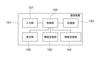
- FIG. 1 is a block diagram of a communication device in a first embodiment of the present invention.
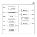
- FIG. 2 is a functional block diagram of the communication device in FIG. 1.
- FIG. 2 is a diagram showing a network including the communication device of FIG. 1.
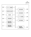
- FIG. FIG. 2 is a functional block diagram when the communication device is a fixedly installed communication device.
- FIG. 3 is a diagram illustrating an example of information elements representing types of communication devices. 3 is a flowchart executed by the communication device in the first embodiment.
- FIG. 3 is a diagram illustrating an example of an information element representing a priority synchronization destination. It is a flowchart which a communication device performs in a second embodiment.
- FIG. 1 is a block diagram showing an example of the configuration of a communication device 101 according to an embodiment of the present invention.
- the communication device 101 includes a control section 102 , a storage section 103 , a wireless reception section 104 , a wireless transmission section 105 , a display section 106 , and an input section 107 .
- the communication device 101 is a communication device that can communicate using a terminal-to-terminal direct communication method called PC5 communication or sidelink communication in the 3GPP standard. Note that in the following description, the communication device 101 may be referred to as a communication terminal device or a terminal.
- the control unit 102 controls the entire communication device 101 by executing a control program stored in the storage unit 103.
- the control unit 102 includes one or more CPUs and MPUs.
- the control unit 102 can execute an OS (Operating System), a driver, an application, or the like.
- CPU is an abbreviation for Central Processing Unit.
- MPU is an abbreviation for Micro-Processing Unit.
- the control unit 102 includes a built-in clock. Note that the control unit 102 may include a GPU (Graphics Processing Unit).
- the storage unit 103 stores a control program executed by the control unit 102. Furthermore, the storage unit 103 stores various information such as communication parameters and captured image data. Various operations described below are performed by the control unit 102 executing a control program stored in the storage unit 103.
- the storage unit 103 includes, for example, a ROM that stores a control program and a RAM that functions as a work area used when the control unit 102 executes a program read from the ROM. Communication parameters and captured image data (image files) are stored in the RAM.
- ROM is an abbreviation for Read Only Memory
- RAM is an abbreviation for Random Access Memory.
- the wireless receiving unit 104 receives the PC5 signal and GNSS signal of the 3GPP standard.
- the wireless transmitter 105 transmits a PC5 signal according to the 3GPP standard.
- the display unit 106 displays characters, images, etc.
- the display unit 106 has an LCD and an LED, and outputs visually perceivable information (visual information).
- the display unit 106 may include a speaker or the like, and may output information that can be recognized audibly (sound information).
- LCD is an abbreviation for Liquid Crystal Display.
- LED is an abbreviation for Light Emitting Diode.
- the display unit 106 may include, for example, a screen touch sensor and allow a user to operate an application via a GUI.
- GUI is an abbreviation for Graphic User Interface.
- the input unit 107 is used when the user performs various inputs to the communication device 101.
- the input unit 107 includes, for example, a mouse, a keyboard, or a touch panel (not shown), and obtains (accepts) user input via these.
- the communication device 101 may include a distance sensor (not shown) that measures the distance to other communication devices.
- FIG. 2 is a block diagram showing an example of the software functional configuration 201 of the communication device 101.
- the software functional configuration 201 includes a signal receiving section 202, a signal transmitting section 203, a data storage section 204, a display control section 205, and a scan control section 206.
- the software functional configuration 201 also includes a synchronization enable/disable determination section 207, a detection section 208, a synchronization processing section 209, a priority synchronization source type setting section 210, and a priority synchronization source type confirmation section 211.
- the signal receiving unit 202 receives PC5 signals and GNSS signals.
- the signal receiving unit 202 acquires broadcast information, which will be described later.
- the signal transmitter 203 transmits the PC5 signal.
- the data storage unit 204 stores and holds software and information such as authentication information.
- the display control unit 205 performs control processing for the screen displayed on the display unit 106.
- the scan control unit 206 scans (detects) whether or not there is a synchronization reference device (another communication device that can be a synchronization source) in the vicinity for synchronizing the physical layer of the PC5 signal.
- a synchronization reference device another communication device that can be a synchronization source
- the synchronization possibility determination unit 207 determines whether synchronization is possible with one or more (at least one) synchronization reference device obtained from the scan result of the scan control unit 206.
- the detection unit 208 detects fixed communication devices and other synchronous reference devices, which will be described later, from among the synchronous reference devices detected (discovered) by the scan by the scan control unit 206.
- a fixed communication device is a communication device (terminal) that is fixedly installed and does not move.
- the synchronization processing unit 209 determines whether to synchronize with a fixed communication device, which will be described later, or with something else, based on the determination result of the synchronization possibility determination unit 207 and the detection result of the detection unit 208, and performs synchronization processing. Execute.
- the priority synchronization source type setting unit 210 sets the synchronization source type to be referred to preferentially from among the types of synchronization reference devices.
- the priority synchronization source type setting unit 210 sets, for example, sl-SyncPriority representing the priority synchronization source in the own device.
- the priority synchronization source type confirmation unit 211 confirms an information element indicating the synchronization source type that should be referred to preferentially in order to synchronize the physical layer.
- Each functional component shown in FIG. 2 can be realized by the control unit 102 (for example, CPU) of the communication device 101 executing a predetermined processing program. Note that some of the functional components 202 to 211 in FIG. 2 may be combined into one functional component. Alternatively, one functional component may be divided into multiple functional components. Furthermore, at least a portion of each functional component shown in FIG. 2 may be implemented using dedicated hardware. When implementing it in hardware, for example, a predetermined compiler may be used to automatically generate a dedicated circuit on the FPGA from a program for realizing each process.
- FPGA is an abbreviation for Field Programmable Gate Array.
- a Gate Array circuit may be formed in the same manner as an FPGA and realized as hardware. Alternatively, it may be realized by an ASIC (Application Specific Integrated Circuit). In this case, the hardware operates under the control of the control unit 102.
- FIG. 3 shows a network 300 including five communication devices 101 described above.
- the communication device 101 when the communication device 101 is fixedly installed, it becomes fixed user equipment (User Equipment) 301 and 302, and when the communication device 101 is used as a movable device, it becomes mobile user equipment 303 and 304. , 305.
- Fixed user equipment 301, 302 may be referred to as fixed terminals.
- Mobile user equipment 303, 304, 305 is, for example, an autonomous vehicle that runs within a factory. The user equipment will be referred to as UE in the following description.
- the fixed UEs 301 and 302 include a fixed terminal information broadcasting section 401 in addition to the configuration shown in FIG.
- the fixed terminal information notification unit 401 reports (transmits) that the own device is a fixed terminal.
- other communication devices 101 can detect the fixed UE by inserting and broadcasting the information FixedUE as the UE type in the Information Element (IE) broadcast by the fixed UE. becomes.
- the notification is performed using, for example, a beacon signal. Broadcast information transmitted from one UE is acquired by being received by the radio receiving section 104 (signal receiving section 202) of another UE.
- FIG. 6 is a flowchart for determining whether the mobile UE 303, which is the communication device 101 of this embodiment, synchronizes with the fixed UE 301.
- the flowchart of FIG. 6 is started in the control unit 102 of the mobile UE 303, for example, when the network 300 is constructed or when the mobile UE 303 joins the network 300. Further, when the mobile UE 303 detects that a new communication device has joined the network 300, the flowchart of FIG. 6 may be started in the control unit 102 of the mobile UE 303.
- the flowchart in FIG. 6 is performed by the control unit 102 of the mobile UE 303 reading and executing a computer program stored in the storage unit 103. In the figure, S stands for Step.
- the mobile UE 303 starts operating using its own internal clock (S601).
- S602 under the control of the scan control unit 206, it is scanned for the presence of a synchronization reference device (another communication device that can be a synchronization source) in the vicinity for synchronizing the physical layer of the PC5 signal.
- a synchronization reference device another communication device that can be a synchronization source
- the mobile UE 303 detects the fixed UE 301 and the mobile UE 304 as synchronization reference devices. That is, the scan control unit 206 detects other communication devices (fixed UE 301 and mobile UE 304) that can become synchronization sources within a predetermined range from the scan control unit 206.
- the priority synchronization source type confirmation unit 211 is used to determine whether sl-SyncPriority, which represents the priority synchronization source in the own device, is Fixed UE, which represents a fixed UE.
- the synchronization processing unit 209 is used to operate in synchronization with the fixed UE 301 (S605).
- the mobile UE 303 is set to preferentially synchronize with the fixed UE (S603: Yes), and when the fixed UE 301 is detected (S604: Yes), the mobile UE 303 can synchronize with the fixed UE 301.
- the fixed UE 301 is set preferentially as the time synchronization source rather than the public wireless base station and the satellite positioning system. .
- the priority synchronization source type confirmation unit 211 is used to determine whether sl-SyncPriority, which represents the priority synchronization source in the own device, has not been set (S607).
- the synchronization processing unit 209 is used to operate in synchronization with the fixed UE (S610).
- the mobile UE 303 is stably connected to the fixed UE 301, so the mobile UE 303 can achieve stable physical layer synchronization.
- the information acquired from the fixed UE 301 is information indicating that the communication device is of a predetermined type that should play the role of the synchronization source
- other communication devices from which the information could be acquired A fixed UE 301 is set as a time synchronization source. Therefore, mobile UE 303 can achieve stable synchronization.
- the mobile UE 303 uses the fixed UE 301 as a reference for synchronization, so that stable synchronization can be achieved.
- sl-SyncPriority described in S603 and S607 in FIG. 6 is an internal parameter of the own device.
- These internal parameters may be set in advance in the communication device 101 or may be set using the input unit 107. Alternatively, the setting may be made with reference to the contents of sl-SyncPriority in an IE broadcast by another UE, as shown in FIG.
- the scan control unit 206 detects other communication devices (fixed UE 301 and mobile UE 304) that can be a synchronization source within a predetermined range from the scan control unit 206; UEs detected as communication devices are not limited to UEs 301 and 304.
- the UEs detected in S602 may be fixed UEs 301 and 302 and mobile UEs 304 and 305. In this case, since two fixed UEs 301 and 302 are detected in S604, a step of selecting one fixed UE (for example, UE 301) is provided between S604 and S605.
- SLSSID is Sidelink Sync. Abbreviation for Signal ID.
- SLSS is composed of two synchronization signals: PSSS: Primary Sidelink Synchronization Signal and SSSS: Secondary Sidelink Synchronization Signal.
- PSSS Primary Sidelink Synchronization Signal
- SSSS Secondary Sidelink Synchronization Signal.
- Sidelink synchronization signals with SLSSIDs from 0 to 167 are used when sidelink synchronization signals are being transmitted based on the synchronization timing of the base station device. Further, side link synchronization signals of SLSSIDs from 168 to 335 are used when the synchronization timing of the base station device is not based.
- the information "Fixed UE” is information indicating that the UE does not move, but because it does not move, it is known to those around it that it is a UE that can stably play the role of a synchronization source within the area. It can be said that it is information that indicates.
- the UE that wants to play the role of a synchronization source can also be configured to broadcast information indicating whether or not it wants to play the role of a synchronization source to its surroundings. In this case, for example, when an operator constructing a PC5 network installs a fixed UE, he or she may set information on the fixed UE indicating that the stationary UE wishes to play the role of a synchronization source. Just do it.
- information indicating that it wants to play the role of a synchronization source and information indicating Fixed UE is set as a factory default setting. It can also be configured to keep
- the number of UEs that configure the network 300 is not limited to five.
- the step of selecting one fixed UE is performed between S604 and S605. establish. Then, the UE with the smallest numerical value of SLSSID is selected from among the plurality of acquired fixed UEs.
- a fixed UE when a fixed UE starts PC5 communication, it must collect (pre-obtain) the SLSSIDs emitted by surrounding UEs in advance and set its own SLSSID so that it does not conflict with other UEs. It can also be configured. In addition, if a situation occurs in which there are multiple fixed UEs having the smallest SLSSID value, negotiation is performed between the fixed UEs, and one of the fixed UEs is configured to perform further control such as changing the SLSSID. You can also do that. Further, the method of avoiding duplication in the event of a collision is not limited to this. For example, the fixed UE with the smallest SLSSID determines the change waiting time using a random number or the like.
- a fixed UE that has reached the change waiting time collects surrounding information to determine whether another fixed UE with the lowest value SLSSID has changed its SLSSID. As a result of the collection, if it is determined that another fixed UE having the smallest SLSSID has not changed its SLSSID, it attempts to avoid collision by resetting its own SLSSID based on a random number or the like. On the other hand, if it is determined as a result of the collection that another fixed UE having the smallest SLSSID has changed its SLSSID, the duplication avoidance process is ended without changing its own SLSSID.
- the process advances to S609, where it is determined whether a fixed UE has been detected, and the process in S610 or S611 is performed depending on the determination result. .
- the determination result in S608 of FIG. 6 is No, subsequent processing is executed depending on whether the SLSSID transmitted from each UE is a specific numerical value.
- the SLSSID broadcast by a standalone UE a fixed UE, another UE connected to the fixed UE, etc.
- the fixed UE that wants to play the role of the synchronization source sets 338 to the SLSSID and starts the PC5 operation.
- the configuration may be configured to allow multiple fixed UEs to broadcast 338 SLSSIDs. You can also do it.
- the fixed UEs 301 and 302 when the fixed UEs 301 and 302 are performing highly accurate time synchronization, the fixed UEs 301 and 302 set the SLSSID to 338 and perform SLSSID notification processing.
- the second embodiment also uses the configuration of the communication device 101 shown in FIG. 1 and the software functional configuration 201 shown in FIG. 2. Further, the network 300 in FIG. 3 is also used in the second embodiment, and the fixed UE configuration in FIG. 4 is also used in the second embodiment.
- FIG. 8 shows a flowchart of synchronization processing executed by the communication device 101 of the second embodiment.
- steps S601 to S608 are the same as in the first embodiment.
- the own device is the mobile user equipment 305.
- S608 it is determined whether the SLSSID transmitted (broadcast) from each UE is 338 (S801). This determination is made by the detection unit 208.
- the fixed UE 302 is a device with an SLSSID of 338 as described above.
- SLSSIDs from 338 to 671 mean that the UE is in standalone operation or is performing time synchronization with a source (synchronization source) through communication of two or more hops via another UE.
- the mobile UE 305 operates in synchronization with the UE (fixed UE 302) whose SLSSID is 338 (S802).
- the mobile UE 305 can be used as a standalone or multiple UE that synchronizes with the source via multiple hops.
- fixed UEs can be prioritized as connection destinations. That is, a stable connection is made to the fixed UE 301 or 302 broadcasting 338 as the SLSSID, and stable physical layer synchronization can be achieved.
- the fixed UEs 301 and 302 may perform highly accurate time synchronization through direct communication.
- the fixed UEs 301 and 302 may be connected via a wired LAN and perform highly accurate time synchronization.
- the mobile UE 303 or the mobile UE 305 is used as the mobile UE 305, but the present invention can also be applied when the mobile UE 302 is the fixed UE 302.
- the configuration of the communication device 101 shown in FIG. 1 and the software functional configuration 201 shown in FIG. 2 are also used in the third embodiment. Further, the network 300 in FIG. 3 is also used in the third embodiment, and the fixed UE configuration in FIG. 4 is also used in the third embodiment.
- the own device is the fixed UE 302
- the fixed UE 302 starts operating with its own built-in clock (S601).
- the fixed UE 302 scans for the presence or absence of priority synchronous devices, and the fixed UE 301, mobile UE 304, and mobile UE 305 are detected.
- the fixed UE 302 uses the priority synchronization source type confirmation unit 211 to determine whether sl-SyncPriority, which represents the priority synchronization source in the own device, is Fixed UE, which represents a fixed UE.
- the fixed UE 302 uses the detection unit 208 to determine whether the fixed UE 301 has been detected (S604).
- the fixed UE 302 operates in synchronization with the fixed UE 301 using the synchronization processing unit 209 (S605).
- the fixed UE 302 uses the priority synchronization source type confirmation unit 211 to determine whether sl-SyncPriority, which represents the priority synchronization source in the own device, has not been set (S607).
- the fixed UE 302 uses the detection unit 208 to determine whether gnss or gnbEnb is detected (S608).
- the fixed UE 302 uses the detection unit 208 to determine whether the fixed UE 301 has been detected (S609).
- the fixed UE 302 operates in synchronization with the fixed UE 301 using the synchronization processing unit 209 (S610).
- the process when the determination result of S604 is No, the process when the determination result of S607 is No, the process when the determination result of S608 is Yes, and the process when the determination result of S609 is No is the same as that of the first embodiment. is the same as
- the present invention provides a system or device with a recording medium recording a software program code that implements the above-mentioned functions, and a computer (CPU, MPU) of the system or device reads the program code stored in the recording medium. It may also be read and executed.
- the program code itself read from the storage medium will implement the functions of the embodiments described above, and the storage medium that stores the program code will constitute the present invention.
- the storage medium for supplying the program code for example, a flexible disk, hard disk, optical disk, magneto-optical disk, CD-ROM, CD-R, magnetic tape, nonvolatile memory card, ROM, DVD, etc. can be used. can.
- the program code read from the storage medium is written into a memory provided in a function expansion board inserted into the computer or a function expansion unit connected to the computer.
- the CPU provided in the function expansion board or function expansion unit may perform part or all of the actual processing to realize the above-mentioned functions.
Landscapes
- Engineering & Computer Science (AREA)
- Computer Networks & Wireless Communication (AREA)
- Signal Processing (AREA)
- Mobile Radio Communication Systems (AREA)
Abstract
Description
図1は本発明の実施形態に係る通信装置101の構成の一例を示すブロック図である。
次に本発明の第二の実施形態を、図8のフローチャートを用いて説明する。
上記した実施形態では、自装置が移動UE303または移動UE305であるとしたが、自装置が固定UE302の場合も、本発明を適用することができる。
本発明は前述の機能を実現するソフトウェアのプログラムコードを記録した記録媒体をシステムあるいは装置に供給し、システムあるいは装置のコンピュータ(CPU、MPU)が記録媒体に格納されたプログラムコードを読み出し実行するようにしてもよい。この場合、記憶媒体から読み出されたプログラムコード自体が前述した実施形態の機能を実現することとなり、そのプログラムコードを記憶した記憶媒体は本発明を構成することになる。
Claims (13)
- サイドリンク通信が可能な通信装置であって、
同期元となり得る他の通信装置であって、サイドリンク通信が可能な他の通信装置を少なくとも1つ検出する検出手段と、
前記検出手段で検出された少なくとも1つの他の通信装置の各々から所定の情報を取得する取得手段と、
同期の優先順位として所定の動作設定がなされている場合であって、前記取得手段で取得された所定の情報に基づき、少なくとも1つの他の通信装置の各々のうちに、同期元の役割を担うべき所定タイプの通信装置であることを示す情報が取得できた他の通信装置があると判断した場合、当該情報が取得できた他の通信装置を、時刻の同期元として設定する第1の設定手段と、
を有することを特徴とする通信装置。 - 前記取得手段は、前記他の通信装置からサイドリンク通信における報知情報を取得し、
前記第1の設定手段は、前記報知情報に前記所定タイプの通信装置であることを示す情報が含まれている場合に、当該情報が取得できた他の通信装置があると判断し、前記所定の動作設定がなされており、且つ、当該情報が取得できた他の通信装置があると判断した場合に、当該情報が取得できた他の通信装置を時刻の同期元として設定することを特徴とする請求項1に記載の通信装置。 - 前記第1の設定手段による同期元の設定は、前記通信装置に到来する電波の強度にかかわらず行われることを特徴とする請求項2に記載の通信装置。
- 前記通信装置は、前記所定の動作設定と、前記所定の動作設定とは異なる第2の動作設定を少なくとも含む複数の動作設定のうちから前記同期の優先順位を示す動作設定を設定する第2の設定手段をさらに備えることを特徴とする請求項1~3のいずれか1項に記載の通信装置。
- 前記同期の優先順位を示す動作設定として前記所定の動作設定がなされている場合、前記第1の設定手段は、公衆無線基地局および衛星測位システムよりも、前記情報が取得できた他の通信装置を、時刻の同期元として優先的に設定することを特徴とする請求項4に記載の通信装置。
- 前記同期元の役割を担うべき所定タイプの通信装置であることを示す情報が複数取得された場合、前記第1の設定手段は、SLSSID(Sidelink Sync. Signal ID)の数値が小さい他の通信装置を、同期元として設定することを特徴とする請求項1~5のいずれか1項に記載の通信装置。
- 前記所定タイプの通信装置は移動しない通信装置であることを特徴とする請求項1~6のいずれか1項に記載の通信装置。
- 前記報知情報は、当該報知情報を報知している通信装置が移動しないことを示す情報を含むことを特徴とする請求項2または3に記載の通信装置。
- 前記第2の設定手段によって、前記同期の優先順位を示す動作設定として前記所定の動作設定とは異なる動作設定が設定された場合、前記第1の設定手段は、公衆無線基地局またはGNSS(Global Navigation Satellite System)を、時刻の同期元として設定することを特徴とする請求項4に記載の通信装置。
- 前記第1の設定手段は、前記同期の優先順位を示す動作設定として前記異なる動作設定場合がなされており、前記公衆無線基地局および前記GNSSを同期元として設定できない場合、前記第1の設定手段は、SLSSIDの数値に基づいて同期先の他の通信装置を決定し、当該決定した他の通信装置を同期元として設定することを特徴とする請求項9に記載の通信装置。
- 前記通信装置が固定設置されている通信装置であって、前記移動しない他の通信装置と有線LAN経由で接続されている場合、前記優先LANを経由して前記移動しない他の通信装置と同期することを特徴とする請求項7に記載の通信装置。
- サイドリンク通信が可能な通信装置の制御方法であって、
同期元となり得る他の通信装置であって、サイドリンク通信が可能な他の通信装置を少なくとも1つ検出する検出工程と、
前記検出工程で検出した少なくとも1つの他の通信装置の各々から所定の情報を取得する取得工程と、
同期の優先順位として所定の動作設定がなされている場合であって、前記取得工程で取得した所定の情報に基づき、同期元の役割を担うべき所定タイプの通信装置であることを示す情報場合、当該情報が取得できた他の通信装置を、時刻の同期元として設定する設定工程と、
を有することを特徴とする制御方法。 - サイドリンク通信が可能な通信装置のコンピュータに、
同期元となり得る他の通信装置であって、サイドリンク通信が可能な他の通信装置を少なくとも1つ検出する検出工程と、
前記検出工程で検出した少なくとも1つの他の通信装置の各々から所定の情報を取得する取得工程と、
前記同期の優先順位として所定の動作設定がなされている場合であって、前記取得手段で取得された所定の情報に基づき、少なくとも1つの他の通信装置の各々のうちに、同期元の役割を担うべき所定タイプの通信装置であることを示す情報が取得できた他の通信装置があると判断した場合、当該情報が取得できた他の通信装置を、時刻の同期元として設定する設定工程と、
を実行させるためのプログラム。
Priority Applications (2)
| Application Number | Priority Date | Filing Date | Title |
|---|---|---|---|
| CN202380052281.2A CN119522611A (zh) | 2022-07-11 | 2023-06-23 | 通信装置、控制通信装置的方法、以及程序 |
| US19/014,810 US20250150994A1 (en) | 2022-07-11 | 2025-01-09 | Communication apparatus, method of controlling communication apparatus, and storage medium |
Applications Claiming Priority (2)
| Application Number | Priority Date | Filing Date | Title |
|---|---|---|---|
| JP2022111105A JP2024009518A (ja) | 2022-07-11 | 2022-07-11 | 通信装置およびその制御方法 |
| JP2022-111105 | 2022-07-11 |
Related Child Applications (1)
| Application Number | Title | Priority Date | Filing Date |
|---|---|---|---|
| US19/014,810 Continuation US20250150994A1 (en) | 2022-07-11 | 2025-01-09 | Communication apparatus, method of controlling communication apparatus, and storage medium |
Publications (1)
| Publication Number | Publication Date |
|---|---|
| WO2024014257A1 true WO2024014257A1 (ja) | 2024-01-18 |
Family
ID=89536490
Family Applications (1)
| Application Number | Title | Priority Date | Filing Date |
|---|---|---|---|
| PCT/JP2023/023255 Ceased WO2024014257A1 (ja) | 2022-07-11 | 2023-06-23 | 通信装置、その制御方法、及びプログラム |
Country Status (4)
| Country | Link |
|---|---|
| US (1) | US20250150994A1 (ja) |
| JP (1) | JP2024009518A (ja) |
| CN (1) | CN119522611A (ja) |
| WO (1) | WO2024014257A1 (ja) |
Citations (1)
| Publication number | Priority date | Publication date | Assignee | Title |
|---|---|---|---|---|
| KR20220043221A (ko) * | 2019-10-04 | 2022-04-05 | 엘지전자 주식회사 | Nr v2x에서 제어 정보에 기반하여 전송 자원을 식별하는 방법 및 동기화 |
-
2022
- 2022-07-11 JP JP2022111105A patent/JP2024009518A/ja active Pending
-
2023
- 2023-06-23 CN CN202380052281.2A patent/CN119522611A/zh active Pending
- 2023-06-23 WO PCT/JP2023/023255 patent/WO2024014257A1/ja not_active Ceased
-
2025
- 2025-01-09 US US19/014,810 patent/US20250150994A1/en active Pending
Patent Citations (1)
| Publication number | Priority date | Publication date | Assignee | Title |
|---|---|---|---|---|
| KR20220043221A (ko) * | 2019-10-04 | 2022-04-05 | 엘지전자 주식회사 | Nr v2x에서 제어 정보에 기반하여 전송 자원을 식별하는 방법 및 동기화 |
Also Published As
| Publication number | Publication date |
|---|---|
| JP2024009518A (ja) | 2024-01-23 |
| US20250150994A1 (en) | 2025-05-08 |
| CN119522611A (zh) | 2025-02-25 |
Similar Documents
| Publication | Publication Date | Title |
|---|---|---|
| US20180332459A1 (en) | Communication apparatus, control method, and non-transitory computer-readable storage medium | |
| JP5611489B2 (ja) | 無線通信システムおよび無線通信装置 | |
| JP3668170B2 (ja) | 無線通信装置 | |
| EP3148260B1 (en) | Power saving of proxy mobile devices in neighbor aware network nan | |
| EP3656306A2 (en) | Radiation imaging system, method of controlling radiation imaging system, and control apparatus | |
| CN107548129B (zh) | 无线通信装置及其控制方法和计算机可读存储介质 | |
| KR100842570B1 (ko) | 이동 단말에서 복수의 영상을 디스플레이 하기 위한 방법및 장치 | |
| US20230070916A1 (en) | Measurement device and measurement method | |
| KR20180108741A (ko) | 동기화 방법 및 장치 | |
| JP2012054799A (ja) | 通信装置 | |
| JP2019057853A (ja) | 情報処理装置、情報処理システム及びプログラム | |
| KR20150132284A (ko) | 스캔 연산들을 수행하기 위한 방법 및 장치 | |
| JP2018097683A (ja) | 表示制御プログラム、表示制御方法および表示制御装置 | |
| KR20160099662A (ko) | 데이터 공유를 위한 방법 및 장치 | |
| US7672290B2 (en) | Dual-mode mobile terminal and method for displaying time information | |
| WO2024014257A1 (ja) | 通信装置、その制御方法、及びプログラム | |
| US10548102B2 (en) | Communication apparatus, control method therefor, and non-transitory computer-readable storage medium for a neighbor awareness network | |
| US11277730B2 (en) | Communication apparatus, method of controlling communication apparatus, and non-transitory computer-readable storage medium | |
| WO2023218900A1 (ja) | 通信装置、通信装置の制御方法、およびプログラム | |
| CN115720378A (zh) | 无线通信装置、无线网络管理装置、控制方法、以及非暂态计算机可读存储介质 | |
| JP2011253025A (ja) | 表示装置及びシステム | |
| US20260040034A1 (en) | Sidelink positioning reference signal processing method and apparatus, terminal, and storage medium | |
| US20240411002A1 (en) | Data processing system in which distance measurement is performed, control method therefor, and storage medium | |
| JP6492924B2 (ja) | 撮像装置、及び撮像プログラム | |
| US20240340817A1 (en) | Communication device, method for controlling communication device, and storage medium |
Legal Events
| Date | Code | Title | Description |
|---|---|---|---|
| 121 | Ep: the epo has been informed by wipo that ep was designated in this application |
Ref document number: 23839431 Country of ref document: EP Kind code of ref document: A1 |
|
| WWE | Wipo information: entry into national phase |
Ref document number: 202380052281.2 Country of ref document: CN |
|
| NENP | Non-entry into the national phase |
Ref country code: DE |
|
| WWP | Wipo information: published in national office |
Ref document number: 202380052281.2 Country of ref document: CN |
|
| 122 | Ep: pct application non-entry in european phase |
Ref document number: 23839431 Country of ref document: EP Kind code of ref document: A1 |