WO2024014252A1 - Theft prevention device and theft prevention method - Google Patents
Theft prevention device and theft prevention method Download PDFInfo
- Publication number
- WO2024014252A1 WO2024014252A1 PCT/JP2023/023100 JP2023023100W WO2024014252A1 WO 2024014252 A1 WO2024014252 A1 WO 2024014252A1 JP 2023023100 W JP2023023100 W JP 2023023100W WO 2024014252 A1 WO2024014252 A1 WO 2024014252A1
- Authority
- WO
- WIPO (PCT)
- Prior art keywords
- electric vehicle
- vehicle
- theft
- unit
- lock
- Prior art date
Links
- 230000002265 prevention Effects 0.000 title claims abstract description 23
- 238000000034 method Methods 0.000 title claims description 33
- 230000004044 response Effects 0.000 claims description 69
- 238000012790 confirmation Methods 0.000 claims description 27
- 238000004891 communication Methods 0.000 abstract description 158
- 238000012795 verification Methods 0.000 description 39
- 238000012545 processing Methods 0.000 description 21
- 238000010586 diagram Methods 0.000 description 18
- 238000012544 monitoring process Methods 0.000 description 16
- 238000001514 detection method Methods 0.000 description 13
- 230000006870 function Effects 0.000 description 9
- 230000001133 acceleration Effects 0.000 description 5
- 230000001419 dependent effect Effects 0.000 description 4
- 238000004590 computer program Methods 0.000 description 3
- 230000007774 longterm Effects 0.000 description 3
- 238000012423 maintenance Methods 0.000 description 3
- 238000009434 installation Methods 0.000 description 2
- 238000005259 measurement Methods 0.000 description 2
- 239000004065 semiconductor Substances 0.000 description 2
- 239000004606 Fillers/Extenders Substances 0.000 description 1
- HBBGRARXTFLTSG-UHFFFAOYSA-N Lithium ion Chemical compound [Li+] HBBGRARXTFLTSG-UHFFFAOYSA-N 0.000 description 1
- 230000005540 biological transmission Effects 0.000 description 1
- 238000007599 discharging Methods 0.000 description 1
- 230000005611 electricity Effects 0.000 description 1
- 238000003384 imaging method Methods 0.000 description 1
- 229910001416 lithium ion Inorganic materials 0.000 description 1
Images


Classifications
-
- B—PERFORMING OPERATIONS; TRANSPORTING
- B60—VEHICLES IN GENERAL
- B60L—PROPULSION OF ELECTRICALLY-PROPELLED VEHICLES; SUPPLYING ELECTRIC POWER FOR AUXILIARY EQUIPMENT OF ELECTRICALLY-PROPELLED VEHICLES; ELECTRODYNAMIC BRAKE SYSTEMS FOR VEHICLES IN GENERAL; MAGNETIC SUSPENSION OR LEVITATION FOR VEHICLES; MONITORING OPERATING VARIABLES OF ELECTRICALLY-PROPELLED VEHICLES; ELECTRIC SAFETY DEVICES FOR ELECTRICALLY-PROPELLED VEHICLES
- B60L15/00—Methods, circuits, or devices for controlling the traction-motor speed of electrically-propelled vehicles
- B60L15/20—Methods, circuits, or devices for controlling the traction-motor speed of electrically-propelled vehicles for control of the vehicle or its driving motor to achieve a desired performance, e.g. speed, torque, programmed variation of speed
-
- B—PERFORMING OPERATIONS; TRANSPORTING
- B60—VEHICLES IN GENERAL
- B60L—PROPULSION OF ELECTRICALLY-PROPELLED VEHICLES; SUPPLYING ELECTRIC POWER FOR AUXILIARY EQUIPMENT OF ELECTRICALLY-PROPELLED VEHICLES; ELECTRODYNAMIC BRAKE SYSTEMS FOR VEHICLES IN GENERAL; MAGNETIC SUSPENSION OR LEVITATION FOR VEHICLES; MONITORING OPERATING VARIABLES OF ELECTRICALLY-PROPELLED VEHICLES; ELECTRIC SAFETY DEVICES FOR ELECTRICALLY-PROPELLED VEHICLES
- B60L3/00—Electric devices on electrically-propelled vehicles for safety purposes; Monitoring operating variables, e.g. speed, deceleration or energy consumption
-
- B—PERFORMING OPERATIONS; TRANSPORTING
- B60—VEHICLES IN GENERAL
- B60L—PROPULSION OF ELECTRICALLY-PROPELLED VEHICLES; SUPPLYING ELECTRIC POWER FOR AUXILIARY EQUIPMENT OF ELECTRICALLY-PROPELLED VEHICLES; ELECTRODYNAMIC BRAKE SYSTEMS FOR VEHICLES IN GENERAL; MAGNETIC SUSPENSION OR LEVITATION FOR VEHICLES; MONITORING OPERATING VARIABLES OF ELECTRICALLY-PROPELLED VEHICLES; ELECTRIC SAFETY DEVICES FOR ELECTRICALLY-PROPELLED VEHICLES
- B60L50/00—Electric propulsion with power supplied within the vehicle
- B60L50/50—Electric propulsion with power supplied within the vehicle using propulsion power supplied by batteries or fuel cells
- B60L50/60—Electric propulsion with power supplied within the vehicle using propulsion power supplied by batteries or fuel cells using power supplied by batteries
-
- B—PERFORMING OPERATIONS; TRANSPORTING
- B60—VEHICLES IN GENERAL
- B60L—PROPULSION OF ELECTRICALLY-PROPELLED VEHICLES; SUPPLYING ELECTRIC POWER FOR AUXILIARY EQUIPMENT OF ELECTRICALLY-PROPELLED VEHICLES; ELECTRODYNAMIC BRAKE SYSTEMS FOR VEHICLES IN GENERAL; MAGNETIC SUSPENSION OR LEVITATION FOR VEHICLES; MONITORING OPERATING VARIABLES OF ELECTRICALLY-PROPELLED VEHICLES; ELECTRIC SAFETY DEVICES FOR ELECTRICALLY-PROPELLED VEHICLES
- B60L53/00—Methods of charging batteries, specially adapted for electric vehicles; Charging stations or on-board charging equipment therefor; Exchange of energy storage elements in electric vehicles
- B60L53/10—Methods of charging batteries, specially adapted for electric vehicles; Charging stations or on-board charging equipment therefor; Exchange of energy storage elements in electric vehicles characterised by the energy transfer between the charging station and the vehicle
- B60L53/14—Conductive energy transfer
-
- B—PERFORMING OPERATIONS; TRANSPORTING
- B60—VEHICLES IN GENERAL
- B60L—PROPULSION OF ELECTRICALLY-PROPELLED VEHICLES; SUPPLYING ELECTRIC POWER FOR AUXILIARY EQUIPMENT OF ELECTRICALLY-PROPELLED VEHICLES; ELECTRODYNAMIC BRAKE SYSTEMS FOR VEHICLES IN GENERAL; MAGNETIC SUSPENSION OR LEVITATION FOR VEHICLES; MONITORING OPERATING VARIABLES OF ELECTRICALLY-PROPELLED VEHICLES; ELECTRIC SAFETY DEVICES FOR ELECTRICALLY-PROPELLED VEHICLES
- B60L53/00—Methods of charging batteries, specially adapted for electric vehicles; Charging stations or on-board charging equipment therefor; Exchange of energy storage elements in electric vehicles
- B60L53/60—Monitoring or controlling charging stations
- B60L53/65—Monitoring or controlling charging stations involving identification of vehicles or their battery types
-
- B—PERFORMING OPERATIONS; TRANSPORTING
- B60—VEHICLES IN GENERAL
- B60L—PROPULSION OF ELECTRICALLY-PROPELLED VEHICLES; SUPPLYING ELECTRIC POWER FOR AUXILIARY EQUIPMENT OF ELECTRICALLY-PROPELLED VEHICLES; ELECTRODYNAMIC BRAKE SYSTEMS FOR VEHICLES IN GENERAL; MAGNETIC SUSPENSION OR LEVITATION FOR VEHICLES; MONITORING OPERATING VARIABLES OF ELECTRICALLY-PROPELLED VEHICLES; ELECTRIC SAFETY DEVICES FOR ELECTRICALLY-PROPELLED VEHICLES
- B60L53/00—Methods of charging batteries, specially adapted for electric vehicles; Charging stations or on-board charging equipment therefor; Exchange of energy storage elements in electric vehicles
- B60L53/60—Monitoring or controlling charging stations
- B60L53/66—Data transfer between charging stations and vehicles
-
- B—PERFORMING OPERATIONS; TRANSPORTING
- B60—VEHICLES IN GENERAL
- B60R—VEHICLES, VEHICLE FITTINGS, OR VEHICLE PARTS, NOT OTHERWISE PROVIDED FOR
- B60R25/00—Fittings or systems for preventing or indicating unauthorised use or theft of vehicles
- B60R25/01—Fittings or systems for preventing or indicating unauthorised use or theft of vehicles operating on vehicle systems or fittings, e.g. on doors, seats or windscreens
- B60R25/04—Fittings or systems for preventing or indicating unauthorised use or theft of vehicles operating on vehicle systems or fittings, e.g. on doors, seats or windscreens operating on the propulsion system, e.g. engine or drive motor
- B60R25/045—Fittings or systems for preventing or indicating unauthorised use or theft of vehicles operating on vehicle systems or fittings, e.g. on doors, seats or windscreens operating on the propulsion system, e.g. engine or drive motor by limiting or cutting the electrical supply to the propulsion unit
-
- B—PERFORMING OPERATIONS; TRANSPORTING
- B60—VEHICLES IN GENERAL
- B60R—VEHICLES, VEHICLE FITTINGS, OR VEHICLE PARTS, NOT OTHERWISE PROVIDED FOR
- B60R25/00—Fittings or systems for preventing or indicating unauthorised use or theft of vehicles
- B60R25/10—Fittings or systems for preventing or indicating unauthorised use or theft of vehicles actuating a signalling device
- B60R25/102—Fittings or systems for preventing or indicating unauthorised use or theft of vehicles actuating a signalling device a signal being sent to a remote location, e.g. a radio signal being transmitted to a police station, a security company or the owner
-
- B—PERFORMING OPERATIONS; TRANSPORTING
- B60—VEHICLES IN GENERAL
- B60R—VEHICLES, VEHICLE FITTINGS, OR VEHICLE PARTS, NOT OTHERWISE PROVIDED FOR
- B60R25/00—Fittings or systems for preventing or indicating unauthorised use or theft of vehicles
- B60R25/30—Detection related to theft or to other events relevant to anti-theft systems
- B60R25/33—Detection related to theft or to other events relevant to anti-theft systems of global position, e.g. by providing GPS coordinates
-
- G—PHYSICS
- G16—INFORMATION AND COMMUNICATION TECHNOLOGY [ICT] SPECIALLY ADAPTED FOR SPECIFIC APPLICATION FIELDS
- G16Y—INFORMATION AND COMMUNICATION TECHNOLOGY SPECIALLY ADAPTED FOR THE INTERNET OF THINGS [IoT]
- G16Y10/00—Economic sectors
- G16Y10/40—Transportation
-
- G—PHYSICS
- G16—INFORMATION AND COMMUNICATION TECHNOLOGY [ICT] SPECIALLY ADAPTED FOR SPECIFIC APPLICATION FIELDS
- G16Y—INFORMATION AND COMMUNICATION TECHNOLOGY SPECIALLY ADAPTED FOR THE INTERNET OF THINGS [IoT]
- G16Y20/00—Information sensed or collected by the things
- G16Y20/20—Information sensed or collected by the things relating to the thing itself
-
- G—PHYSICS
- G16—INFORMATION AND COMMUNICATION TECHNOLOGY [ICT] SPECIALLY ADAPTED FOR SPECIFIC APPLICATION FIELDS
- G16Y—INFORMATION AND COMMUNICATION TECHNOLOGY SPECIALLY ADAPTED FOR THE INTERNET OF THINGS [IoT]
- G16Y40/00—IoT characterised by the purpose of the information processing
- G16Y40/10—Detection; Monitoring
-
- H—ELECTRICITY
- H02—GENERATION; CONVERSION OR DISTRIBUTION OF ELECTRIC POWER
- H02J—CIRCUIT ARRANGEMENTS OR SYSTEMS FOR SUPPLYING OR DISTRIBUTING ELECTRIC POWER; SYSTEMS FOR STORING ELECTRIC ENERGY
- H02J13/00—Circuit arrangements for providing remote indication of network conditions, e.g. an instantaneous record of the open or closed condition of each circuitbreaker in the network; Circuit arrangements for providing remote control of switching means in a power distribution network, e.g. switching in and out of current consumers by using a pulse code signal carried by the network
-
- H—ELECTRICITY
- H02—GENERATION; CONVERSION OR DISTRIBUTION OF ELECTRIC POWER
- H02J—CIRCUIT ARRANGEMENTS OR SYSTEMS FOR SUPPLYING OR DISTRIBUTING ELECTRIC POWER; SYSTEMS FOR STORING ELECTRIC ENERGY
- H02J7/00—Circuit arrangements for charging or depolarising batteries or for supplying loads from batteries
Definitions
- the present disclosure relates to a theft countermeasure device and a theft countermeasure method for responding to the theft of an electric vehicle.
- Patent Document 1 discloses a technique for prohibiting charging of a stolen vehicle. In the technique disclosed in Patent Document 1, when an electric vehicle is charged at a charging facility, charging is prohibited if identification code verification is unsuccessful.
- One purpose of this disclosure is to provide a theft countermeasure device and a theft countermeasure method that make it easier to recover a stolen electric vehicle.
- the theft prevention device of the present disclosure provides identification information for identifying whether the electric vehicle is a stolen vehicle when the electric vehicle charges its own battery from an external charger.
- an identification information acquisition unit that acquires the electric vehicle from the electric vehicle; a theft identification unit that uses the identification information acquired by the identification information acquisition unit to identify whether the electric vehicle is a stolen vehicle; and a theft identification unit that identifies whether the electric vehicle is stolen.
- the electric vehicle includes a lock instruction unit that locks the electric vehicle to prevent driving operation based on the identification of the electric vehicle.
- the theft countermeasure method of the present disclosure is performed by at least one processor, when the electric vehicle charges its own battery from an external charger, the electric vehicle detects whether the electric vehicle is a stolen vehicle.
- FIG. 1 is a diagram showing an example of a schematic configuration of a vehicle system.
- FIG. 2 is a diagram illustrating an example of a schematic configuration of a vehicle-side unit.
- FIG. 1 is a diagram showing an example of a schematic configuration of a charging stand.
- FIG. 2 is a sequence diagram illustrating an example of the flow of theft identification-related processing in the vehicle system.
- FIG. 1 is a diagram showing an example of a schematic configuration of a vehicle system.
- FIG. 1 is a diagram showing an example of a schematic configuration of a charging stand.
- FIG. 1 is a diagram showing an example of a schematic configuration of a vehicle system.
- FIG. 1 is a diagram showing an example of a schematic configuration of a charging stand.
- FIG. 1 is a diagram showing an example of a schematic configuration of a charging stand.
- FIG. 1 is a diagram showing an example of a schematic configuration of a vehicle system.
- FIG. 2 is a diagram illustrating an example of a schematic configuration of a vehicle-side unit.
- FIG. 1 is a diagram showing an example of a schematic configuration of a charging stand.
- FIG. 1 is a diagram showing an example of a schematic configuration of a vehicle system.
- FIG. 2 is a diagram illustrating an example of a schematic configuration of a vehicle-side unit.
- FIG. 1 is a diagram showing an example of a schematic configuration of a charging stand.
- FIG. 1 is a diagram showing an example of a schematic configuration of a vehicle system.
- FIG. 1 is a diagram showing an example of a schematic configuration of a charging stand.
- FIG. 2 is a diagram illustrating an example of a schematic configuration of a vehicle-side unit.
- the vehicle system 9 shown in FIG. 1 includes an electric vehicle 1, a charging station 3, an authentication server 4, a user terminal 5, and a security server 6.
- Examples of the electric vehicle 1 include an EV (Electric Vehicle), a PHV (Plug-in Hybrid Vehicle), and the like.
- the electric vehicle 1 may be a range extender vehicle that drives a motor by generating electricity from an engine.
- Electric vehicle 1 includes a vehicle-side unit 10. The vehicle-side unit 10 will be described later.
- the charging stand 3 is used to charge a battery 11 of the electric vehicle 1, which will be described later.
- the charging stand 3 corresponds to an external charger of the electric vehicle 1.
- the electric vehicle 1 and the charging station 3 are connected by a cable Ca during charging.
- a power supply plug is provided at one end of the cable Ca.
- the other end of the cable Ca is, for example, always connected to the charging stand 3.
- the power supply plug of the cable Ca is detachably connected to an inlet portion 12 of the vehicle unit 10, which will be described later. By connecting the power supply plug of the cable Ca to the inlet portion 12, power can be supplied from the charging stand 3 to the battery 11 of the electric vehicle 1.
- the cable Ca includes a power line for power feeding. Power is supplied from the charging station 3 to the battery 11 of the electric vehicle 1 via this power line.
- the cable Ca also includes a signal line for communication. Communication between the charging station 3 and the vehicle-side unit 10 is performed via this communication line.
- the charging station 3 can adopt a quick charging method as a charging method. In this embodiment, the quick charging method will be described using, for example, the CHAdeMO (registered trademark) standard.
- the authentication server 4 communicates with the charging station 3 via the network.
- the authentication server 4 stores in advance identification information for identifying authorized users (hereinafter referred to as authorized identification information).
- the authentication server 4 performs authentication for permission to charge.
- the authentication server 4 compares the regular identification information with the identification information transmitted from the charging station 3. This verification is called regular verification. It is also assumed that the authentication server 4 has previously registered identification information of a stolen vehicle (hereinafter referred to as theft identification information).
- theft identification information The authentication server 4 compares the theft identification information with the identification information transmitted from the charging station 3. This verification is called stolen vehicle verification.
- the authentication server 4 sends the results of the regular verification and stolen vehicle verification to the charging station 3.
- the user terminal 5 is a mobile terminal carried by a regular user of the electric vehicle 1.
- the user terminal 5 may be a multifunctional mobile phone such as a smartphone.
- the user terminal 5 has a function of communicating via a network.
- the user terminal 5 has a function of displaying information.
- the user terminal 5 has a function of receiving input from the user.
- the security server 6 communicates with the charging station 3 via the network.
- the security server 6 is a server of the police or a security company.
- the security server 6 receives a theft report, which will be described later, transmitted via the network.
- the security server 6 receives the theft report, the police or a security company can go to secure the stolen vehicle.
- the vehicle-side unit 10 includes a battery 11, an inlet section 12, and a charging ECU 13, as shown in FIG.
- the charging ECU 13 is connected to, for example, an in-vehicle LAN (see LAN in FIG. 2).
- the battery 11 is a running battery for supplying electric power to the motor that is the driving force source of the electric vehicle 1.
- This battery 11 corresponds to an on-vehicle battery.
- the battery 11 includes a plurality of battery cells electrically connected in series.
- a secondary battery such as a lithium ion battery can be used.
- the battery 11 is connected to an SMR (System Main Relay) that is a relay that disconnects and disconnects the battery 11 from an electrical load.
- SMR System Main Relay
- Connection cutoff here refers to switching between energization and cutoff. It is assumed that the SMR is controlled by, for example, the charging ECU 13.
- the inlet portion 12 is the connection destination of the aforementioned power supply plug. By connecting the power supply plug and the inlet section 12, the battery 11 can be charged from the charging stand 3.
- the inlet section 12 has a detection sensor that detects connection with the power supply plug and a lock mechanism that prevents the power supply plug from being unintentionally removed. This locking mechanism corresponds to a fixing mechanism.
- the inlet portion 12 is attached to the body of the electric vehicle 1.
- the inlet portion 12 is provided with a plurality of terminals. Some of these terminals are connected to the power line of the cable Ca. Another part of the plurality of terminals is connected to the signal line of the cable Ca.
- connection signal is a signal indicating that the power supply plug and the inlet portion 12 are connected.
- the charging ECU 13 is an electronic control device that manages charging and discharging of the battery 11.
- the charging ECU 13 is mainly composed of a microcomputer including a processor, memory, I/O, and a bus connecting these.
- the charging ECU 13 monitors the charging state of the battery 11 and controls operations related to charging.
- the charging ECU 13 includes a communication unit 131 as a sub-functional block that communicates with the charging stand 3 via the signal line of the cable Ca.
- the charging ECU 13 controls driving of the SMR.
- the charging ECU 13 controls the operation and release of the lock mechanism.
- the charging ECU 13 acquires battery information such as the cell voltage and cell temperature of the battery 11.
- the charging ECU 13 calculates the SOC (State Of Charge) of the battery 11 using this battery information.
- the charging ECU 13 sequentially calculates the SOC of the battery 11 and specifies the remaining charge amount.
- the charging ECU 13 When the connection between the inlet section 12 and the power supply plug is detected, the charging ECU 13 electrically connects the power supply plug and the battery 11 to start charging the battery 11.
- the communication unit 131 may transmit identification information of the electric vehicle 1 and a power supply request signal to the charging station 3.
- the identification information is information that identifies each electric vehicle 1.
- the charging ECU 13 controls the locking mechanism of the inlet section 12 to lock the connection between the power supply plug and the inlet section 12.
- Charging ECU 13 adjusts the amount of charge based on the remaining amount of charge of battery 11 .
- Charging ECU 13 determines whether battery 11 is fully charged or not based on the calculated SOC.
- the communication unit 131 may transmit a power supply stop signal to the charging stand 3.
- the charging ECU 13 receives a request from the charging station 3 through the communication unit 131, the charging ECU 13 performs processing according to the request.
- the charging stand 3 includes a control device 30 and a power supply section 31, as shown in FIG.
- the power supply unit 31 supplies power from a power supply source to the electric vehicle 1 via the power line of the cable Ca under the control of the control device 30.
- the power supply section 31 may be a relay or the like that turns on and off the supply of current under the control of the control device 30.
- the control device 30 is mainly composed of a microcomputer that includes a processor, memory, I/O, and a bus that connects these.
- the control device 30 executes various processes by executing a control program stored in a memory.
- Memory as used herein is a non-transitory tangible storage medium that non-temporarily stores computer-readable programs and data. Further, the non-transitional physical storage medium is realized by a semiconductor memory, a magnetic disk, or the like.
- the control device 30 includes a vehicle communication section 301, a theft identification section 302, a network (hereinafter referred to as NW) communication section 303, a charging permission section 304, a charging control section 305, and a response instruction section 306 as functional blocks.
- NW network
- This control device 30 corresponds to a theft countermeasure device.
- the execution of the processing of each functional block of the control device 30 by the computer corresponds to the execution of the theft countermeasure method.
- some or all of the functions executed by the control device 30 may be configured in hardware using one or more ICs.
- some or all of the functional blocks included in the control device 30 may be realized by a combination of software execution by a processor and hardware components.
- the vehicle communication unit 301 communicates with the communication unit 131 via the signal line of the cable Ca in a state where the inlet unit 12 and the power supply plug are connected.
- the vehicle communication unit 301 acquires the identification information and the power supply request signal.
- This vehicle communication section 301 corresponds to an identification information acquisition section.
- the processing in the vehicle communication unit 301 corresponds to an identification information acquisition step.
- the power supply stop signal is transmitted from the communication unit 131
- the vehicle communication unit 301 acquires the power supply stop signal.
- the theft identification unit 302 uses the identification information acquired by the vehicle communication unit 301 to identify whether the electric vehicle 1 is a stolen vehicle. This process by the theft identification unit 302 corresponds to a theft identification process.
- the theft identification unit 302 causes the NW communication unit 303 to send the identification information acquired by the vehicle communication unit 301 to the authentication server 4.
- the NW communication unit 303 communicates with terminals and servers connected to the network via the network.
- the authentication server 4 uses the identification information sent from the NW communication section 303 to perform the above-mentioned regular verification and stolen vehicle verification.
- the NW communication unit 303 receives the results of regular verification and stolen vehicle verification from the authentication server 4 .
- the theft identifying unit 302 identifies the electric vehicle 1 as a stolen vehicle when the stolen vehicle verification result received by the NW communication unit 303 is successful. On the other hand, if the stolen vehicle verification is unsuccessful, the theft identification unit 302 identifies the electric vehicle 1 as not a stolen vehicle. Therefore, the identification information acquired by vehicle communication unit 301 corresponds to identification information for specifying whether electric vehicle 1 is a stolen vehicle.
- the charging permission unit 304 permits charging.
- the charging permission unit 304 permits charging when the result of the regular verification received by the NW communication unit 303 is that the verification is successful.
- the charging permission unit 304 may be configured to not permit charging when the theft identification unit 302 identifies the electric vehicle 1 as a stolen vehicle. According to this, charging of a stolen vehicle can be prevented.
- the charging control unit 305 starts power supply to the electric vehicle 1 when the vehicle communication unit 301 acquires a power supply request signal and the charging permission unit 304 permits charging. On the other hand, charging control unit 305 stops power supply to electric vehicle 1 when vehicle communication unit 301 acquires a power supply stop signal.
- the charging control unit 305 controls the power supply unit 31 to start or stop power supply. The period from the start of power supply to the electric vehicle 1 until the power supply is stopped is called a charging period.
- the response instruction unit 306 issues instructions for responding to the theft of the electric vehicle 1 (hereinafter referred to as response instructions).
- the response instruction unit 306 issues a response instruction when the theft identification unit 302 identifies the electric vehicle 1 as a stolen vehicle.
- the response instruction section 306 includes a confirmation instruction section 361, a lock instruction section 362, and a report instruction section 363 as sub-functional blocks.
- the confirmation instruction unit 361 instructs the user terminal 5 to confirm whether locking of the electric vehicle 1 is acceptable (hereinafter referred to as acceptance/disapproval confirmation instruction).
- the confirmation instruction unit 361 causes the NW communication unit 303 to transmit an acceptance/rejection confirmation instruction to the user terminal 5 via the network.
- the lock of the electric vehicle 1 is a lock that prevents driving operation of the electric vehicle 1.
- the lock that prevents the driving operation of the electric vehicle 1 may be a lock that prevents the electric vehicle 1 from moving.
- the user terminal 5 corresponding to the electric vehicle 1 may be identified based on the correspondence between the identification information of the electric vehicle 1 and the identification information of the user terminal 5 that are registered in advance. This correspondence relationship may be stored in the authentication server 4, for example.
- the authentication server 4 may transmit the identification information of the user terminal 5 corresponding to the electric vehicle 1 along with the stolen vehicle verification result.
- the confirmation instruction unit 361 may cause the user terminal 5 to transmit an acceptance/rejection confirmation instruction based on the identification information of the user terminal 5.
- the identification information of the user terminal 5 the address of the user terminal 5 on the network may be used.
- the user terminal 5 When the user terminal 5 receives the instruction to confirm whether or not to lock the electric vehicle 1, it displays a message to confirm whether or not to lock the electric vehicle 1. Then, the user terminal 5 receives an input of a response from the user regarding this acceptance/disapproval (hereinafter referred to as an acceptance/disapproval response input). The user terminal 5 returns this acceptance/disapproval response input to the NW communication unit 303 via the network. The NW communication unit 303 acquires this acceptance/disapproval response input transmitted from the user terminal 5. Therefore, this NW communication section 303 corresponds to an answer acquisition section.
- an acceptance response input input of an acceptance/disapproval response to permit locking
- an acceptance/disapproval input that does not permit locking is referred to as a refusal response input.
- the lock instruction unit 362 causes the electric vehicle 1 to be locked based on the fact that the theft identification unit 302 identifies the electric vehicle 1 as a stolen vehicle. This process in the lock instruction section 362 corresponds to a lock instruction step.
- the lock instruction unit 362 may lock the electric vehicle 1 so that it cannot be moved by transmitting a signal to turn off the SMR from the vehicle communication unit 301. According to this, the electric vehicle 1 becomes unable to move. Therefore, a stolen electric vehicle can be recovered more easily.
- the signal that turns off the SMR corresponds to a lock instruction.
- the charging ECU 13 of the electric vehicle 1 turns off the SMR when the communication unit 131 receives this signal. As a result, the motor cannot receive power from the battery 11, and the electric vehicle 1 cannot be moved. According to the above configuration, by using a signal that turns off the SMR, it is possible to prevent the electric vehicle 1 from moving with a small number of bits. Therefore, even when performing communication in accordance with the CHAdeMO standard, it is possible to suppress the number of bits used and prevent the electric vehicle 1 from moving easily.
- the lock instruction unit 362 may lock the vehicle when the theft identification unit 302 identifies the vehicle as a stolen vehicle and the NW communication unit 303 receives a rejection response input. That is, it is preferable that the lock instruction unit 362 also adds the fact that the NW communication unit 303 has received a rejection response input as a condition for performing the lock. The lock instruction unit 362 does not need to lock the vehicle even if the NW communication unit 303 obtains a consent response input or the theft identification unit 302 identifies the vehicle as a stolen vehicle. According to this, by adding the user's approval or disapproval to the locking conditions, it becomes possible to suppress locking due to erroneous judgment.
- the lock instruction unit 362 preferably causes the vehicle to be temporarily locked even if the NW communication unit 303 is unable to obtain an acceptance/rejection input.
- the lock described above is the permanent lock.
- the temporary lock is a lock that prevents driving operation of the electric vehicle 1 only within a predetermined period of time.
- the predetermined time may be a time shorter than the time during which the main lock continues. For example, this lock will not be released unless a release operation is performed from a terminal such as a dealer.
- the temporary lock may be released within several minutes to several tens of minutes, for example.
- the electric vehicle 1 can be temporarily locked. Therefore, even if the user does not input an acceptance/disapproval response, the stolen electric vehicle 1 can be recovered more easily.
- the report instruction unit 363 transmits a theft report to the security server 6 when the lock instruction unit 362 performs locking.
- the report instruction unit 363 transmits this information from the NW communication unit 303 to the security server 6 via the network.
- the theft report may include the fact that the electric vehicle 1 is a stolen vehicle and the current location of the electric vehicle 1. This makes it possible for the security server 6 to grasp the location of the stolen vehicle and go to secure it. As a result, the stolen electric vehicle 1 can be recovered more easily.
- As the current position of the electric vehicle 1, information on the installation position of the charging station 3 may be used. This is because the current position of the electric vehicle 1 being charged at the charging station 3 can be estimated to be approximately the same as the installation position of the charging station 3.
- the power supply plug of the charging station 3 and the inlet section 12 of the electric vehicle 1 are connected.
- the communication unit 131 of the electric vehicle 1 transmits identification information and a power supply request signal to the charging station 3.
- the vehicle communication unit 301 of the charging station 3 receives and acquires this identification information and the power supply request signal.
- the NW communication unit 303 of the charging station 3 transmits the identification information acquired at t2 to the authentication server 4.
- Authentication server 4 receives this identification information.
- the authentication server 4 performs regular verification and stolen vehicle verification using the identification information received at t3. In FIG. 4, the explanation will be continued by taking as an example a case where stolen vehicle verification is successful.
- the authentication server 4 replies to the charging station 3 with the verification results of the regular verification and the stolen vehicle verification.
- the NW communication unit 303 receives this verification result.
- the theft identifying unit 302 identifies the electric vehicle 1 as a stolen vehicle based on the stolen vehicle verification result.
- the confirmation instruction unit 361 of the charging station 3 causes the NW communication unit 303 to transmit an acceptance/rejection confirmation instruction to the user terminal 5.
- the user terminal 5 receives this acceptance confirmation instruction.
- the user terminal 5 displays a message for confirming whether or not to lock the electric vehicle 1.
- the explanation will be continued by taking as an example a case where the user terminal 5 accepts an input of an acceptance/disapproval response to permit locking.
- the user terminal 5 replies to the NW communication unit 303 with an input of an acceptance/rejection answer.
- the confirmation instruction unit 361 of the charging station 3 causes the vehicle communication unit 301 to transmit to the electric vehicle 1 an instruction to lock the electric vehicle 1 so that it cannot be moved.
- a signal to turn off the SMR is transmitted from the vehicle communication unit 301 via the signal line of the cable Ca.
- Communication unit 131 of electric vehicle 1 receives this signal.
- the charging ECU 13 locks the electric vehicle 1 so that it cannot be moved by turning off the SMR.
- the report instruction unit 363 of the charging station 3 causes the NW communication unit 303 to transmit a theft report to the security server 6.
- the configuration may be such that after the process at t9, the process at t12 is performed before the process at t10.
- Embodiment 2 In the first embodiment, a configuration is shown in which the electric vehicle 1 is locked so that it cannot be moved by turning off the SMR, but the present invention is not necessarily limited to this.
- the configuration of Embodiment 2 below may be used.
- An example of the configuration of Embodiment 2 will be described below with reference to the drawings.
- the vehicle system 9a includes an electric vehicle 1, a charging station 3a, an authentication server 4, a user terminal 5, and a security server 6, as shown in FIG.
- the vehicle system 9a is the same as the vehicle system 9 of Embodiment 1, except that the vehicle system 9a includes a charging station 3a instead of the charging station 3.
- the charging stand 3a includes a control device 30a, a power supply section 31, and an emergency stop button 32, as shown in FIG.
- the charging station 3a is the same as the charging station 3 of the first embodiment, except that it includes an emergency stop button 32 and a control device 30a instead of the control device 30.
- the charging stand 3a also corresponds to a charger external to the electric vehicle 1.
- the emergency stop button 32 is an input unit for interrupting charging of the electric vehicle 1 from the charging stand 3a during the charging period.
- the charging control unit 305 stops power supply to the electric vehicle 1.
- a signal indicating an emergency stop of charging (hereinafter referred to as an emergency stop signal) is transmitted from the vehicle communication unit 301 to the communication unit 131.
- the charging ECU 13 of the electric vehicle 1 receives the emergency stop signal through the communication unit 131, the charging ECU 13 ends processing related to charging such as adjusting the charging amount. Furthermore, when the communication unit 131 receives an emergency stop signal, the charging ECU 13 releases the lock mechanism of the inlet unit 12 .
- the charging stand 3 may be configured to include the emergency stop button 32.
- the control device 30a includes a vehicle communication section 301, a theft identification section 302, a NW communication section 303, a charging permission section 304, a charging control section 305, and a response instruction section 306a as functional blocks.
- the control device 30a is the same as the control device 30 of the first embodiment except that it includes a response instruction section 306a instead of the response instruction section 306.
- This control device 30a also corresponds to a theft prevention device.
- the execution of the processing of each functional block of the control device 30a by the computer also corresponds to the execution of the theft countermeasure method.
- the response instruction section 306a includes a confirmation instruction section 361, a lock instruction section 362a, and a notification instruction section 363 as sub-functional blocks.
- the response instruction section 306a is the same as the response instruction section 306 of the first embodiment, except that it includes a lock instruction section 362a instead of the lock instruction section 362.
- the lock instruction unit 362a causes the vehicle communication unit 301 to transmit a signal that keeps the locking mechanism of the inlet unit 12 in operation instead of the signal that turns off the SMR. Except for this point, the lock instruction section 362a is the same as the lock instruction section 362 of the first embodiment. This process in the lock instruction section 362a also corresponds to a lock instruction step.
- the signal that continues to maintain the operation of the locking mechanism of the inlet section 12 will be referred to as a lock maintenance signal below.
- the lock maintenance signal also corresponds to a lock instruction.
- the charging ECU 13 of the electric vehicle 1 When the charging ECU 13 of the electric vehicle 1 receives the lock maintenance signal through the communication unit 131, the charging ECU 13 continues to maintain the lock mechanism of the inlet unit 12. In other words, the charging ECU 13 prevents the locking mechanism of the inlet section 12 from being released even when the communication section 131 receives the emergency stop signal. According to this, when the locking mechanism of the electric vehicle 1 is activated in response to an instruction from the locking instruction section 362a, the locking mechanism can be made unreleasable regardless of the operation of the emergency stop button 32. Therefore, the stolen electric vehicle 1 can be recovered more easily.
- the present invention is not necessarily limited to this.
- the electric vehicle 1 may be provided with an emergency stop button that interrupts charging.
- the electric vehicle 1 may be locked so that it cannot be moved by means other than those described in the first and second embodiments.
- the electric vehicle 1 may be locked so that the user cannot ride and drive the electric vehicle 1.
- the electric vehicle 1 may be prevented from moving by disabling the accessory switch from being turned off.
- the electric vehicle 1 may be prevented from moving by using an immobilizer to prevent the driving power source from starting.
- Embodiment 4 The present invention is not limited to the configuration of the embodiment described above, but may be the configuration of the fourth embodiment below. An example of the configuration of Embodiment 4 will be described below with reference to the drawings.
- the vehicle system 9b includes an electric vehicle 1, a charging station 3b, an authentication server 4, a user terminal 5, and a security server 6, as shown in FIG.
- the vehicle system 9b is the same as the vehicle system 9 of Embodiment 1, except that the vehicle system 9b includes a charging station 3b instead of the charging station 3.
- the charging stand 3b includes a control device 30b and a power supply section 31b.
- the power supply unit 31b is similar to the charging stand 3 of the first embodiment, except that a plurality of types of power supply sources are required to be connected. Examples of the plurality of types of power supply sources to which the power supply section 31b is connected include a commercial power source, a storage battery, and the like.
- the integrated controller may control how the charging station 3b receives power from the plurality of types of power supply sources.
- the charging stand 3b also corresponds to a charger external to the electric vehicle 1.
- the control device 30b includes a vehicle communication section 301, a theft identification section 302, a NW communication section 303, a charging permission section 304, a charging control section 305b, and a response instruction section 306b as functional blocks.
- the control device 30b includes a charging control section 305b instead of the charging control section 305.
- the control device 30b includes a response instruction section 306b instead of the response instruction section 306.
- the control device 30b is similar to the control device 30 of the first embodiment except for these points.
- This control device 30b also corresponds to a theft countermeasure device. Further, the execution of the processing of each functional block of the control device 30b by the computer also corresponds to the execution of the theft countermeasure method.
- the charging control unit 305b is similar to the charging control unit 305 of Embodiment 1, except that it also performs processing for accepting discharge from the electric vehicle 1 (hereinafter referred to as discharge-related processing).
- the charging control unit 305b performs discharge-related processing when a discharge instruction signal is transmitted by a discharge instruction unit 364, which will be described later.
- the charging control unit 305b may perform a process of returning the power discharged from the electric vehicle 1 via the cable Ca to the storage battery connected to the power supply unit 31b. This allows the battery 11 of the electric vehicle 1 to be discharged.
- the response instruction section 306b includes a confirmation instruction section 361, a lock instruction section 362, a notification instruction section 363, and a discharge instruction section 364 as sub-functional blocks.
- the response instruction section 306b is similar to the response instruction section 306 of the first embodiment, except that it includes a discharge instruction section 364.
- the discharge instruction unit 364 also causes the battery 11 to be discharged when the lock instruction unit 362 performs locking.
- the discharge instruction unit 364 may cause the vehicle communication unit 301 to transmit a signal instructing the discharge of the battery 11 (hereinafter referred to as a discharge instruction signal) to the communication unit 131.
- the charging ECU 13 of the electric vehicle 1 causes the battery 11 to discharge when the communication unit 131 receives the discharge instruction signal. According to this, the battery 11 of the stolen vehicle is discharged, further making it difficult to move the stolen vehicle.
- Embodiment 5 The present invention is not limited to the configuration of the above-described embodiment, but may be a configuration of the following fifth embodiment. An example of the configuration of Embodiment 5 will be described below with reference to the drawings.
- the vehicle system 9c includes an electric vehicle 1c, a charging station 3c, an authentication server 4, a user terminal 5, and a security server 6, as shown in FIG.
- the vehicle system 9c includes an electric vehicle 1c instead of the electric vehicle 1.
- the vehicle system 9c includes a charging stand 3c instead of the charging stand 3.
- the vehicle system 9c is the same as the vehicle system 9 of the first embodiment except for these points.
- the electric vehicle 1c is an electric vehicle capable of automatic operation.
- Automated driving refers to automated driving in which the driver has no obligation to monitor safety driving (hereinafter simply referred to as monitoring obligation).
- the term "automated driving” referred to here may be defined as automatic driving in which the system can perform all driving tasks, except under specific conditions such as roads that cannot be handled or extreme environments. In other words, it may be automatic driving at an automation level corresponding to highly automated driving.
- Automated driving here may mean automated driving in which the system can perform all driving tasks under any environment. In other words, the vehicle may be operated at an automation level equivalent to complete automation.
- Electric vehicle 1c includes a vehicle-side unit 10c.
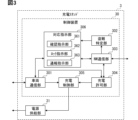
- the vehicle side unit 10c includes a battery 11, an inlet section 12, a charging ECU 13c, a communication module 14, a locator 15, a map database (hereinafter referred to as map DB) 16, a vehicle condition sensor 17, a surrounding monitoring sensor 18, It includes a vehicle control ECU 19, a body ECU 20, and an automatic driving ECU 21.
- the charging ECU 13, the communication module 14, the locator 15, the map DB 16, the vehicle condition sensor 17, the vehicle control ECU 19, the body ECU 20, and the automatic driving ECU 21 are connected to, for example, an in-vehicle LAN (see LAN in FIG. 10).
- the communication module 14 transmits and receives information to and from a center outside the own vehicle via wireless communication. In other words, it performs wide area communication.
- the communication module 14 may send and receive information to and from other vehicles via wireless communication.
- inter-vehicle communication may be performed.
- the communication module 14 may transmit and receive information to and from a roadside machine installed on the roadside via wireless communication.
- road-to-vehicle communication may be performed.
- the communication module 14 may receive information about surrounding vehicles transmitted from surrounding vehicles of the host vehicle via a roadside device. Further, the communication module 14 may receive information on surrounding vehicles transmitted from surrounding vehicles of the host vehicle via wide area communication via the center.
- the locator 15 includes a GNSS (Global Navigation Satellite System) receiver and an inertial sensor.
- the GNSS receiver receives positioning signals from multiple positioning satellites.
- the inertial sensor includes, for example, a gyro sensor and an acceleration sensor.
- the locator 15 sequentially measures the vehicle position of the own vehicle (hereinafter referred to as the own vehicle position) by combining the positioning signal received by the GNSS receiver and the measurement result of the inertial sensor.
- the vehicle position may be expressed by latitude and longitude coordinates, for example. Note that the vehicle position measurement may also be performed using a travel distance obtained from signals sequentially output from a vehicle speed sensor mounted on the vehicle, which will be described later.
- the map DB 16 is a nonvolatile memory that stores high-precision map data.
- High-precision map data is map data with higher precision than map data used for route guidance in the navigation function.
- the map DB 16 may also store map data used for route guidance.
- the high-precision map data includes information that can be used for automatic driving, such as information on the three-dimensional shape of the road, information on the number of lanes, and information indicating the direction of travel allowed for each lane.
- the high-precision map data may also include information on node points indicating the positions of both ends of road markings such as lane markings, for example.
- the locator 15 may be configured to use three-dimensional shape information of the road without using a GNSS receiver.
- the locator 15 may be configured to identify the vehicle position using three-dimensional shape information of the road and detection results from the surrounding monitoring sensor 18.
- the surrounding monitoring sensor 18 LIDAR (Light Detection and Ranging/Laser Imaging Detection and Ranging) that detects point groups of feature points of road shapes and structures may be used.
- a surrounding monitoring camera may be used as the surrounding monitoring sensor 18.
- the three-dimensional shape information of the road may be generated based on a captured image by REM (Road Experience Management).
- map data distributed from the center may be received via wide area communication via the communication module 14 and stored in the map DB 16.
- the map DB 16 may be a volatile memory, and the communication module 14 may sequentially acquire map data of an area corresponding to the position of the vehicle.
- the vehicle condition sensor 17 is a group of sensors for detecting various conditions of the own vehicle. Examples of the vehicle condition sensor 17 include a vehicle speed sensor and a seating sensor. The vehicle speed sensor detects the speed of the own vehicle. The seating sensor detects whether or not an occupant of the own vehicle is seated. As the seating sensor, a pressure-sensitive sensor embedded in the seating surface of each seat may be used. The vehicle condition sensor 17 outputs detected sensing information to the in-vehicle LAN. Note that the sensing information detected by the vehicle condition sensor 17 may be output to the in-vehicle LAN via an ECU installed in the vehicle.
- the surroundings monitoring sensor 18 monitors the surrounding environment of the own vehicle.
- the surroundings monitoring sensor 18 detects obstacles around the own vehicle.
- the surroundings monitoring sensor 18 detects road markings such as lane markings around the vehicle.
- the surrounding monitoring sensor 18 may be a surrounding monitoring camera, millimeter wave radar, sonar, LIDAR, or the like.
- the surrounding surveillance camera images a predetermined area around the vehicle.
- Millimeter wave radar, sonar, and LIDAR transmit search waves to a predetermined range around the vehicle.
- millimeter wave radar, sonar, and LIDAR will be referred to as exploration wave sensors.
- the surroundings monitoring camera sequentially outputs the sequentially captured images to the automatic driving ECU 21 as sensing information.
- the exploration wave sensor sequentially outputs a scanning result based on a received signal obtained when receiving a reflected wave reflected by an obstacle to the automatic driving ECU 21 as sensing information.
- the sensing information detected by the surroundings monitoring sensor 18 may be output to the in-vehicle LAN.
- the vehicle control ECU 19 is an electronic control device that controls the running of the own vehicle. Travel control includes acceleration/deceleration control and steering control.
- the vehicle control ECU 19 includes a steering ECU that performs steering control, a power unit control ECU that performs acceleration/deceleration control, a brake ECU, and the like.
- the vehicle control ECU 19 performs driving control by outputting control signals to each driving control device mounted on the own vehicle. Examples of the travel control device include an electronically controlled throttle, a brake actuator, and an EPS (Electric Power Steering) motor.
- the body ECU 20 is an electronic control device that controls the electrical components of the own vehicle. The body ECU 20 locks and unlocks the doors of the vehicle by controlling the door lock motor.
- the automatic driving ECU 21 is an electronic control device that realizes automatic driving functions.
- the automatic driving ECU 21 recognizes the surrounding environment of the own vehicle.
- the vehicle position of the own vehicle acquired from the locator 15 is used to recognize the surrounding environment.
- Map data acquired from the map DB 16 is used to recognize the surrounding environment.
- Sensing information acquired from the surrounding monitoring sensor 18 is used to recognize the surrounding environment.
- the automatic driving ECU 21 recognizes the shape and movement state of objects around the own vehicle from sensing information acquired from the surroundings monitoring sensor 18. By combining this recognition result with the vehicle's position and map data, a virtual space is created that reproduces the actual driving environment in three dimensions.
- the automatic driving ECU 21 determines a travel plan for driving the own vehicle based on the recognized surrounding environment. As the travel plan, a long-term travel plan and a short-term travel plan are generated. In the long-term and medium-term travel plans, a route is generated to direct the vehicle to a set destination. In the short-term travel plan, a planned travel trajectory is generated using the generated virtual space around the own vehicle to realize driving according to the long-term and medium-term travel plan. Specifically, the execution of steering for changing lanes, acceleration/deceleration for speed adjustment, steering and braking for avoiding obstacles, etc. is determined. The automatic driving ECU 21 executes acceleration/deceleration control, steering control, etc. of the own vehicle according to the determined travel plan.
- the automatic driving ECU 21 switches control authority for driving operation.
- manual operation is a state in which the driver has control over the driving operation.
- automatic driving is defined as a state in which the control authority for driving operations lies with the own vehicle's system.
- the battery 11 and inlet section 12 are the same as in the first embodiment.
- the charging ECU 13c includes a communication section 131 and a boarding detection section 132 as sub-functional blocks.
- the charging ECU 13c is the same as the charging ECU 13 of the first embodiment, except that some processes are different.
- the boarding detection unit 132 detects boarding of a passenger in the electric vehicle 1c.
- the occupancy detection unit 132 may detect the occupant's entry into the electric vehicle 1c since the aforementioned occupancy sensor detects the seating.
- the boarding detection unit 132 may also include the fact that the door of the electric vehicle 1c has been opened and then closed as a condition for detecting boarding.
- the opening/closing of the door of the electric vehicle 1c may be determined by the occupancy detection unit 132 based on the signal from the door courtesy switch.
- the charging ECU 13c When the charging ECU 13c receives a restraint instruction, which will be described later, from the charging station 3 through the communication unit 131, it waits until the riding detection unit 132 detects the rider, and then locks the vehicle. In the fifth embodiment, as a lock, the electric vehicle 1c is locked and the electric vehicle 1c is locked so that no driving operation of the electric vehicle 1c is accepted.
- the charging ECU 13c may lock all the doors of the electric vehicle 1c via the body ECU 20.
- the charging ECU 13c may fix the control authority for the driving operation to the system of the own vehicle via the automatic driving ECU 21. Thereby, it is possible to prevent the driving operation of the electric vehicle 1c from being accepted. According to this, it becomes possible to trap the thief of the electric vehicle 1c in the electric vehicle 1c and prevent him from freely moving the electric vehicle 1c. Therefore, the stolen electric vehicle 1c can be recovered more easily.
- the automatic driving ECU 21 When the automatic driving ECU 21 receives a driving instruction, which will be described later, through the communication unit 131, the electric vehicle 1c is automatically driven to the police station after being locked by the charging ECU 13c.
- the automatic driving ECU 21 can automatically drive the electric vehicle 1c to the police station by determining a travel plan in which the destination is the police station. As the destination, for example, the police station closest to the position of the electric vehicle 1c may be selected from the map data. According to this, by having the police identify the thief of the electric vehicle 1c, the stolen electric vehicle 1c can be recovered more easily.
- the charging stand 3c includes a control device 30c and a power supply section 31, as shown in FIG.
- the charging station 3c is the same as the charging station 3 of the first embodiment except that it includes a control device 30c instead of the control device 30.
- the charging stand 3c corresponds to an external charger of the electric vehicle 1c.
- the control device 30c includes a vehicle communication section 301, a theft identification section 302, a NW communication section 303, a charging permission section 304, a charging control section 305, and a response instruction section 306c as functional blocks.
- the control device 30c is the same as the control device 30 of the first embodiment except that it includes a response instruction section 306c instead of the response instruction section 306.
- This control device 30c also corresponds to a theft countermeasure device. Further, the execution of the processing of each functional block of the control device 30c by the computer also corresponds to the execution of the theft countermeasure method.
- the response instruction section 306c includes a confirmation instruction section 361, a lock instruction section 362c, a notification instruction section 363, and a travel instruction section 365 as sub-functional blocks.
- the response instruction section 306c includes a travel instruction section 365.
- the correspondence instruction section 306c includes a lock instruction section 362c instead of the lock instruction section 362.
- the correspondence instruction section 306c is similar to the correspondence instruction section 306 of the first embodiment except for these points.
- the lock instruction unit 362c is the same as the lock instruction unit 362 of the first embodiment, except that the instruction transmitted from the vehicle communication unit 301 is different. Even when the lock is to be performed, the lock instruction unit 362c waits until it is detected that the occupant has entered the electric vehicle 1c, and then transmits an instruction to perform the lock to restrain the occupant. This instruction is called a constraint instruction.
- the restraint instruction corresponds to a lock instruction.
- the lock that restrains the occupant is a lock that prevents the electric vehicle 1c from being locked and from accepting driving operations of the electric vehicle 1c.
- the travel instruction unit 365 causes the electric vehicle 1 to be locked in accordance with the restraint instruction, and then transmits an instruction (hereinafter referred to as a travel instruction) to cause the electric vehicle 1 to automatically drive to the police station.
- Travel instruction section 365 causes vehicle communication section 301 to transmit a travel instruction to communication section 131 .
- a configuration is shown in which the electric vehicle 1c is driven automatically to the police station, but the configuration is not necessarily limited to this.
- a configuration may be adopted in which the electric vehicle 1c does not perform automatic driving without monitoring obligation.
- the electric vehicle 1c may be configured to perform locking in accordance with the restraint instruction.
- the charging stations 3, 3a, 3b, and 3c transmit locking instructions to the electric vehicles 1 and 1c through communication via the signal line of the cable Ca, but this is not necessarily the case. do not have.
- the configuration of Embodiment 6 below may be used. An example of the configuration of Embodiment 6 will be described below with reference to the drawings.
- the vehicle system 9d shown in FIG. 12 includes an electric vehicle 1d, a charging station 3d, an authentication server 4, a user terminal 5, and a security server 6.
- the vehicle system 9d includes an electric vehicle 1d instead of the electric vehicle 1.
- the vehicle system 9d includes a charging station 3d instead of the charging station 3.
- the electric vehicle 1 of the third embodiment includes a vehicle-side unit 10b instead of the vehicle-side unit 10.
- the vehicle system 9d is the same as the vehicle system 9 of the first embodiment except for these points.
- the electric vehicle 1d is the same as the electric vehicle 1 of the first embodiment, except that it includes a vehicle-side unit 10d instead of the vehicle-side unit 10.
- the vehicle-side unit 10d includes a battery 11, an inlet section 12, a charging ECU 13, and a wireless communication device 22, as shown in FIG.
- the charging ECU 13 and the wireless communication device 22 are connected to, for example, an in-vehicle LAN (see LAN in FIG. 13).
- the vehicle-side unit 10d is the same as the vehicle-side unit 10 of the first embodiment, except that it includes a wireless communication device 22.
- the wireless communication device 22 is a communication module for communicating by wireless communication.
- the wireless communication device 22 performs short-range wireless communication according to, for example, a short-range wireless communication standard.
- the wireless communication device 22 may be configured to perform short-range wireless communication according to a short-range wireless communication standard such as Bluetooth (registered trademark) or BLE (Bluetooth Low Energy).
- Bluetooth registered trademark
- BLE Bluetooth Low Energy
- the charging stand 3d includes a control device 30d and a power supply section 31, as shown in FIG.
- the control device 30d includes a vehicle communication section 301d, a theft identification section 302, a NW communication section 303, a charging permission section 304, a charging control section 305, and a response instruction section 306 as functional blocks.
- the charging station 3d is the same as the charging station 3 of the first embodiment except that it includes a vehicle communication section 301d instead of the vehicle communication section 301.
- the charging stand 3d also corresponds to a charger outside the electric vehicle 1.
- This control device 30d also corresponds to a theft countermeasure device. Further, the execution of the processing of each functional block of the control device 30d by the computer also corresponds to the execution of the theft countermeasure method.
- the vehicle communication unit 301d is similar to the vehicle communication unit 301 of the first embodiment, except that it can also transmit and receive information with the wireless communication device 22 by wireless communication. Therefore, this vehicle communication section 301d also corresponds to an identification information acquisition section. Further, the processing in this vehicle communication section 301d also corresponds to the identification information acquisition step.
- the vehicle communication unit 301d transmits the lock instruction from the lock instruction unit 362 to the wireless communication device 22. In the sixth embodiment as well, communication regarding authentication may be configured to be performed via the signal line of the cable Ca. Note that the vehicle communication unit 301d may be configured to include a member that performs communication via the signal line of the cable Ca and a member that performs wireless communication.
- the sixth embodiment shows a configuration in which communication related to authentication is performed via the signal line of cable Ca
- the present invention is not necessarily limited to this.
- communication regarding authentication may also be performed wirelessly.
- the configuration of the sixth embodiment and the configurations of the first to fifth embodiments may be combined.
- Embodiment 6 and Embodiment 4 are combined, a configuration may be adopted in which the discharge instruction is transmitted via wireless communication.
- Embodiment 6 and Embodiment 5 are combined, a configuration may be adopted in which the driving instruction is transmitted by wireless communication.
- Embodiment 8 In the above-described embodiment, a configuration was shown in which regular verification and stolen vehicle verification are performed by the authentication server 4 or the charging stations 3, 3a, 3b, 3c, and 3d, but the present invention is not necessarily limited to this.
- the configuration of Embodiment 8 below may be used.
- An example of the configuration of Embodiment 8 will be described below with reference to the drawings.
- the vehicle system 9d shown in FIG. 15 includes an electric vehicle 1e, a charging station 3e, a user terminal 5, a security server 6, and an authentication information server 7.
- the vehicle system 9e includes an electric vehicle 1e instead of the electric vehicle 1.
- the vehicle system 9e includes a charging stand 3e instead of the charging stand 3.
- the vehicle system 9e includes an authentication information server 7 instead of the authentication server 4.
- the vehicle system 9e is the same as the vehicle system 9 of the first embodiment except for these points.
- the electric vehicle 1e is the same as the electric vehicle 1 of the first embodiment except that it includes a vehicle-side unit 10e instead of the vehicle-side unit 10.
- the authentication information server 7 communicates with the charging station 3e via the network.
- the authentication information server 7 stores regular identification information in advance.
- Theft identification information is registered in advance in the authentication information server 7.
- the charging stand 3e includes a control device 30e and a power supply section 31, as shown in FIG.
- the charging station 3e is the same as the charging station 3 of the first embodiment except that it includes a control device 30e instead of the control device 30.
- the charging stand 3e also corresponds to an external charger of the electric vehicle 1e.
- the control device 30e includes a vehicle communication section 301, a NW communication section 303, a charging permission section 304e, a charging control section 305, and a relay section 307 as functional blocks.
- the control device 30e does not include the theft identification section 302 and the response instruction section 306.
- the control device 30e includes a relay section 307.
- the control device 30e is similar to the control device 30 of the first embodiment except for these points.
- the vehicle communication unit 301 of the charging station 3e acquires this power supply request signal.
- the relay unit 307 acquires the regular identification information and theft identification information from the authentication information server 7 when the vehicle communication unit 301 acquires the power supply signal.
- the relay unit 307 acquires the regular identification information and theft identification information via the NW communication unit 303.
- the relay unit 307 causes the vehicle communication unit 301 to transmit the acquired regular identification information and theft identification information to the electric vehicle 1e.
- regular verification and stolen vehicle verification are performed using this regular identification information and theft identification information.
- the vehicle communication unit 301 receives the results of the regular verification and stolen vehicle verification transmitted from the electric vehicle 1e.
- the charging permission unit 304e permits charging when the result of the regular verification received by the vehicle communication unit 301 is successful.
- the charging permission unit 304e may be configured to not permit charging if the stolen vehicle verification result received by the vehicle communication unit 301 is successful. According to this, charging of a stolen vehicle can be prevented.
- the vehicle-side unit 10e includes a battery 11, an inlet section 12, a charging ECU 13e, a communication module 14, and a locator 15, as shown in FIG.
- the charging ECU 13e, the communication module 14, and the locator 15 are connected to, for example, an in-vehicle LAN (see LAN in FIG. 17).
- the vehicle unit 10e includes a communication module 14 and a locator 15.
- the vehicle-side unit 10e includes a charging ECU 13e instead of the charging ECU 13.
- the vehicle-side unit 10e is the same as the vehicle-side unit 10 of the first embodiment except for these points.
- the communication module 14 is similar to the communication module 14 of the fifth embodiment.
- the communication module 14 sends and receives information via the network.
- the locator 15 is similar to the locator 15 of the fifth embodiment.
- the charging ECU 13e includes a communication section 131, an identification information acquisition section 133, an authentication section 134, a confirmation instruction section 135, an answer acquisition section 136, a lock instruction section 137, and a report instruction section 138 as sub-functional blocks.
- Communication unit 131 is similar to communication unit 131 of charging ECU 13.
- the charging ECU 13e executes various processes by executing a control program stored in a memory.
- Memory as used herein is a non-transitory tangible storage medium that non-temporarily stores computer-readable programs and data. Further, the non-transitional physical storage medium is realized by a semiconductor memory, a magnetic disk, or the like. It is assumed that identification information for identifying each electric vehicle 1e is stored in advance in the nonvolatile memory of the charging ECU 13e.
- This charging ECU 13e also corresponds to a theft prevention device. Further, the execution of the processing of each functional block of the charging ECU 13e by the computer corresponds to the execution of the theft countermeasure method. Note that some or all of the functions executed by the charging ECU 13e may be configured in hardware using one or more ICs. Further, some or all of the functional blocks included in the charging ECU 13e may be realized by a combination of software execution by a processor and hardware components.
- the identification information acquisition unit 133 acquires the identification information of the own vehicle from the nonvolatile memory of the charging ECU 13e when the connection between the inlet unit 12 and the power supply plug is detected. That is, the identification information acquisition unit 133 acquires the identification information of the electric vehicle 1e when starting charging of the battery 11.
- the processing in this identification information acquisition unit 133 also corresponds to an identification information acquisition step.
- the communication unit 131 transmits a power supply request signal to the charging stand 3e when starting charging of the battery 11. Furthermore, the communication unit 131 receives the regular identification information and theft identification information returned from the charging station 3e in response to the transmission of the power supply request signal.
- the authentication unit 134 compares the identification information acquired by the identification information acquisition unit 133 with the regular identification information received by the communication unit 131. In other words, regular matching is performed.
- the authentication unit 134 compares the identification information acquired by the identification information acquisition unit 133 with the theft identification information received by the communication unit 131. In other words, stolen vehicle verification is performed.
- the communication unit 131 transmits the results of the regular verification and stolen vehicle verification performed by the authentication unit 134 to the vehicle communication unit 301.
- the authentication unit 134 identifies the electric vehicle 1e as a stolen vehicle when the stolen vehicle verification results in a successful verification.
- This authentication section 134 also corresponds to a theft identification section. Further, the processing performed by the authentication unit 134 also corresponds to the theft identification process.
- the confirmation instruction unit 135 instructs the user terminal 5 to confirm whether or not to lock the electric vehicle 1e (that is, an instruction to confirm whether or not to lock the electric vehicle 1e).
- the confirmation instruction unit 135 may cause the communication module 14 to transmit the acceptance/rejection confirmation instruction to the user terminal 5 via the network.
- the lock of the electric vehicle 1e is a lock that prevents driving operation of the electric vehicle 1e.
- the lock that prevents the driving operation of the electric vehicle 1e may be, for example, a lock that prevents the electric vehicle 1e from moving.
- the lock that prevents the driving operation of the electric vehicle 1e may be a lock that prevents the electric vehicle 1e from being locked and from accepting the driving operation of the electric vehicle 1e.
- the user terminal 5 corresponding to the electric vehicle 1 may be identified based on the correspondence between the identification information of the electric vehicle 1 and the identification information of the user terminal 5 that are registered in advance. This correspondence relationship may be stored in the nonvolatile memory of the electric vehicle 1, for example.
- the confirmation instruction unit 135 may cause the user terminal 5 to transmit an acceptance/rejection confirmation instruction based on the identification information of the user terminal 5.
- the identification information of the user terminal 5 the address of the user terminal 5 on the network may be used.
- the user terminal 5 When the user terminal 5 receives the instruction to confirm whether or not to lock the electric vehicle 1, it displays a message to confirm whether or not to lock the electric vehicle 1. Then, the user terminal 5 receives an input of a response from the user regarding this acceptance/disapproval (that is, an input of an acceptance/disapproval response). The user terminal 5 returns this acceptance/disapproval response input to the communication module 14 via the network.
- the answer acquisition unit 136 acquires this yes/no answer input received by the communication module 14. If the answer acquisition unit 136 is unable to obtain an acceptance/rejection input within a predetermined time after transmitting the acceptance/rejection confirmation instruction, it may be determined that the acceptance/rejection input has not been obtained.
- the input of an acceptance/disapproval response to permit locking is called an acceptance response input.
- an acceptance/disapproval input that does not permit locking is referred to as a refusal response input.
- the lock instruction unit 137 causes the electric vehicle 1e to be locked based on the authentication unit 134 identifying the electric vehicle 1e as a stolen vehicle. This process in the lock instruction section 137 also corresponds to a lock instruction step.
- the lock instruction unit 137 may lock the electric vehicle 1e so that it cannot be moved by turning off the SMR. According to this, the electric vehicle 1e becomes unable to move. Therefore, a stolen electric vehicle can be recovered more easily.
- the lock instruction unit 137 may lock the electric vehicle 1e so that it cannot be moved by continuing to maintain the locking mechanism of the inlet unit 12.
- the lock instruction section 137 prevents the locking mechanism of the inlet section 12 from being released even when the communication section 131 receives the above-mentioned emergency stop signal.
- the locking mechanism of the electric vehicle 1 is activated in response to an instruction from the locking instruction section 137, the locking mechanism can be made unreleasable regardless of the operation of the emergency stop button. Therefore, the stolen electric vehicle 1e can be recovered more easily.
- the emergency stop button is an input unit for interrupting charging of the battery 11 from the charging stand 3e.
- the emergency stop button may be provided on the charging station 3e or on the electric vehicle 1e.
- the lock instruction unit 137 may lock the vehicle when the authentication unit 134 identifies the vehicle as a stolen vehicle and the response acquisition unit 136 receives a rejection response input. That is, it is preferable that the lock instruction unit 137 also adds the fact that the response acquisition unit 136 has received a rejection response input as a condition for performing the lock. The lock instruction unit 137 does not have to lock the vehicle even if the response acquisition unit 136 acquires a consent response input or the authentication unit 134 identifies the vehicle as a stolen vehicle. According to this, by adding the user's approval or disapproval to the locking conditions, it becomes possible to suppress locking due to erroneous judgment.
- the lock instruction unit 137 preferably causes the above-mentioned temporary lock to be performed even if the response acquisition unit 136 is unable to obtain an acceptance/disapproval response input. According to this, even if the user does not notice the confirmation of approval or disapproval of locking on the user terminal 5 and does not input an acceptance/disapproval response, the electric vehicle 1e can be temporarily locked. Therefore, even if the user does not input an acceptance/disapproval response, the stolen electric vehicle 1e can be recovered more easily.
- the report instruction unit 138 transmits a theft report to the security server 6 when the lock instruction unit 137 performs locking.
- the report instruction unit 138 may transmit this information from the communication module 14 to the security server 6 via the network.
- the theft report may include the fact that the electric vehicle 1e is a stolen vehicle and the current location of the electric vehicle 1e. This makes it possible for the security server 6 to grasp the location of the stolen vehicle and go to secure it. As a result, the stolen electric vehicle 1e can be recovered more easily.
- the own vehicle position measured by the locator 15 may be used as the current position of the electric vehicle 1e.
- Embodiment 8 and the configurations of Embodiments 3 to 6 may be combined.
- the communication unit 131 may transmit an instruction to the charging station 3e to perform the above-described discharge-related processing. Further, when the charging ECU 13e causes the lock instruction unit 137 to perform the locking, the charging ECU 13e may also cause the battery 11 to be discharged.
- lock instruction section 137 may lock all doors of electric vehicle 1c via body ECU 20 after waiting until boarding is detected.
- Riding may be detected by providing the charging ECU 13e with a riding detection section 132. Further, after the lock instruction unit 137 performs this locking, the charging ECU 13e instructs the automatic driving ECU 21 to travel, and the electric vehicle 1c may automatically travel to the police station.
- a configuration may be adopted in which, for example, regular identification information and stolen identification information are transmitted and received by wireless communication.
- the boarding detection section 132, the identification information acquisition section 133, the authentication section 134, the confirmation instruction section 135, the answer acquisition section 136, the lock instruction section 137, and the notification instruction section 138 are configured to be included in an electronic control device other than the charging ECU 13e. Good too. In this case, this electronic control device other than the charging ECU 13e corresponds to the theft prevention device.
- control unit and the method described in the present disclosure may be implemented by a dedicated computer constituting a processor programmed to perform one or more functions embodied by a computer program.
- the apparatus and techniques described in this disclosure may be implemented with dedicated hardware logic circuits.
- the apparatus and techniques described in this disclosure may be implemented by one or more special purpose computers configured by a combination of a processor executing a computer program and one or more hardware logic circuits.
- the computer program may also be stored as instructions executed by a computer on a computer-readable non-transitory tangible storage medium.
- an electric vehicle (1, 1c, 1d, 1e) charges its battery (11) from an external charger (3, 3a, 3b, 3c, 3d, 3e), the electric vehicle is stolen.
- an identification information acquisition unit (301, 301d, 133) that acquires identification information for specifying whether or not the electric vehicle is a vehicle;
- a theft identification unit (302, 134) that identifies whether the electric vehicle is a stolen vehicle using the identification information acquired by the identification information acquisition unit;
- a theft countermeasure device comprising: a lock instruction unit (362, 362a, 362c, 137) that causes the electric vehicle to be locked to prevent driving operation of the electric vehicle based on the theft identification unit identifying the electric vehicle as a stolen vehicle; .
- the lock instruction unit (362, 362a) is a theft countermeasure device that locks the electric vehicle (1, 1d, 1e) so that it cannot be moved.
- a theft countermeasure device included in the charger (3, 3a, 3b, 3c, 3d) or a server (4) communicably connected to the charger.
- the theft countermeasure device according to technical idea 3,
- the lock instruction unit (362) transmits a signal from the charger to the electric vehicle (1) to turn off a relay that disconnects the battery from the driving power source of the electric vehicle.
- a theft prevention device that locks the vehicle so that it cannot be moved.
- the theft countermeasure device according to technical idea 2 or 5
- the electric vehicle (1, 1e) and the charger are connected to each other by a cable including a power line when charging the battery,
- the lock instruction unit (362a, 137) prevents the electric vehicle from moving by continuing to operate a fixing mechanism that fixes the electric vehicle and the charger so that the connection via the cable cannot be released.
- Anti-theft device that locks the device.
- the lock instruction unit includes an emergency stop button (an emergency stop button) that forcibly releases the fixing mechanism before the charging of the battery is completed, based on the fact that the electric vehicle is identified as a stolen vehicle by the theft identification unit. 32) A theft countermeasure device that prevents the fixing mechanism from being released even if the locking mechanism is operated.
- the lock instruction unit (362c) may cause the electric vehicle (1c) to be locked based on the theft identifying unit identifying the electric vehicle (1c) as a stolen vehicle.
- the theft countermeasure device locks the electric vehicle and locks the electric vehicle so that no driving operation is accepted, after waiting until a passenger is detected to be riding the electric vehicle.
- the theft countermeasure device is capable of autonomous driving to the destination, A theft countermeasure device comprising a travel instruction unit (365) that causes the electric vehicle to automatically drive to a police station after locking the electric vehicle and locking the electric vehicle so as not to accept driving operations of the electric vehicle.
- a theft countermeasure device comprising a travel instruction unit (365) that causes the electric vehicle to automatically drive to a police station after locking the electric vehicle and locking the electric vehicle so as not to accept driving operations of the electric vehicle.
- a theft countermeasure device comprising a discharge instruction section (364) that causes the battery to be discharged when the lock instruction section causes the lock to be performed.
- a confirmation instruction unit (361, 135) that instructs a user terminal of a regular user of the electric vehicle to confirm whether or not the lock is accepted via a network
- an answer acquisition unit (303, 136) that acquires, via the network, an answer input regarding acceptance or disapproval of the lock, which is received by the user terminal
- the lock instruction unit is configured to control the operation of the electric vehicle when the theft identification unit identifies the electric vehicle as a stolen vehicle and the response acquisition unit acquires a response input that does not permit the lock.
- a theft countermeasure device that causes a lock that prevents an operation to be performed, but prevents the lock from being performed when the answer acquisition unit obtains a response input that permits the lock.
- the theft countermeasure device is configured to control the driving operation of the electric vehicle when the theft identification unit identifies the electric vehicle as a stolen vehicle, even if the response acquisition unit cannot acquire the response input.
- a theft prevention device that locks the device only within a predetermined period of time.
- the theft prevention device includes a report instruction section (363, 138) that causes the police or a security company to be notified that the electric vehicle is a stolen vehicle and the current location of the electric vehicle when the lock instruction section performs the lock.
- a report instruction section (363, 138) that causes the police or a security company to be notified that the electric vehicle is a stolen vehicle and the current location of the electric vehicle when the lock instruction section performs the lock.
Abstract
A theft prevention device comprises: a vehicle communication unit (301) that acquires, from an electric vehicle (1), identification information for identifying whether the electric vehicle (1) is a stolen vehicle, when the electric vehicle charges a battery of the vehicle from a charging station (3); a theft identification unit (302) that identifies whether the electric vehicle is a stolen vehicle using the identification information acquired by the vehicle communication unit (301); and a lock instruction unit (362) that causes the electric vehicle to be locked to prevent driving operation on the basis of the theft identification unit (302) identifying the electric vehicle as a stolen vehicle.
Description
この出願は、2022年7月14日に日本に出願された特許出願第2022-113451号を基礎としており、基礎の出願の内容を、全体的に、参照により援用している。
This application is based on Patent Application No. 2022-113451 filed in Japan on July 14, 2022, and the content of the underlying application is incorporated by reference in its entirety.
本開示は、電動車両の盗難に対応するための盗難対応装置及び盗難対応方法に関するものである。
The present disclosure relates to a theft countermeasure device and a theft countermeasure method for responding to the theft of an electric vehicle.
車両外部の電源から供給される電力によって、車載のバッテリを充電する電動車両が知られている。特許文献1には、盗難車両の充電を禁止する技術が開示されている。特許文献1に開示の技術では、充電設備での電動車両の充電時において、識別コードの照合が不成立となった場合に、充電を禁止する。
Electric vehicles are known that charge an on-vehicle battery with power supplied from a power source external to the vehicle. Patent Document 1 discloses a technique for prohibiting charging of a stolen vehicle. In the technique disclosed in Patent Document 1, when an electric vehicle is charged at a charging facility, charging is prohibited if identification code verification is unsuccessful.
しかしながら、充電を禁止したとしても、盗難された電動車両を回収できないおそれがある。詳しくは、以下の通りである。電動車両を充電する場合、電動車両の残容量が0にはなっていないのが一般的である。よって、盗難された電動車両の充電を禁止したとしても、逃走されてしまうおそれがある。
However, even if charging is prohibited, there is a risk that a stolen electric vehicle may not be recovered. The details are as follows. When charging an electric vehicle, the remaining capacity of the electric vehicle is generally not zero. Therefore, even if charging of a stolen electric vehicle is prohibited, there is a risk that the stolen electric vehicle may be stolen.
この開示の1つの目的は、盗難された電動車両をより容易に回収可能とする盗難対応装置及び盗難対応方法を提供することにある。
One purpose of this disclosure is to provide a theft countermeasure device and a theft countermeasure method that make it easier to recover a stolen electric vehicle.
上記目的は独立請求項に記載の特徴の組み合わせにより達成され、また、下位請求項は、開示の更なる有利な具体例を規定する。請求の範囲に記載した括弧内の符号は、一つの態様として後述する実施形態に記載の具体的手段との対応関係を示すものであって、本開示の技術的範囲を限定するものではない。
The object is achieved by the combination of features recited in the independent claims, and the subclaims define further advantageous embodiments of the disclosure. The numerals in parentheses described in the claims indicate correspondence with specific means described in the embodiments described later as one aspect, and do not limit the technical scope of the present disclosure.
上記目的を達成するために、本開示の盗難対応装置は、電動車両が外部の充電器から自車のバッテリに充電を行う際に、電動車両が盗難車か否かを特定するための識別情報を、電動車両から取得する識別情報取得部と、識別情報取得部で取得する識別情報を用いて、電動車両が盗難車か否かを特定する盗難特定部と、盗難特定部で電動車両が盗難車と特定したことをもとに、電動車両の運転操作を妨げるロックを行わせるロック指示部とを備える。
In order to achieve the above object, the theft prevention device of the present disclosure provides identification information for identifying whether the electric vehicle is a stolen vehicle when the electric vehicle charges its own battery from an external charger. an identification information acquisition unit that acquires the electric vehicle from the electric vehicle; a theft identification unit that uses the identification information acquired by the identification information acquisition unit to identify whether the electric vehicle is a stolen vehicle; and a theft identification unit that identifies whether the electric vehicle is stolen. The electric vehicle includes a lock instruction unit that locks the electric vehicle to prevent driving operation based on the identification of the electric vehicle.
上記目的を達成するために、本開示の盗難対応方法は、少なくとも1つのプロセッサにより実行される、電動車両が外部の充電器から自車のバッテリに充電を行う際に、電動車両が盗難車か否かを特定するための識別情報を、電動車両から取得する識別情報取得工程と、識別情報取得工程で取得する識別情報を用いて、電動車両が盗難車か否かを特定する盗難特定工程と、盗難特定工程で電動車両が盗難車と特定したことをもとに、電動車両の運転操作を妨げるロックを行わせるロック指示工程とを含む。
In order to achieve the above object, the theft countermeasure method of the present disclosure is performed by at least one processor, when the electric vehicle charges its own battery from an external charger, the electric vehicle detects whether the electric vehicle is a stolen vehicle. an identification information acquisition step of acquiring identification information for identifying whether the electric vehicle is a stolen vehicle; and a theft identification step of identifying whether the electric vehicle is a stolen vehicle using the identification information acquired in the identification information acquisition step. , a lock instruction step for instructing a lock that prevents driving operation of the electric vehicle based on the fact that the electric vehicle is identified as a stolen vehicle in the theft identification step.
これらによれば、外部の充電器から電動車両のバッテリを充電する際に、この電動車両が盗難車か否かを特定することが可能になる。また、盗難車と特定したことをもとに、電動車両の運転操作を妨げるロックを行わせるので、充電場所から電動車両を盗難者が自由に移動できなくなる。その結果、盗難された電動車両がより容易に回収可能となる。
According to these, when charging the battery of an electric vehicle from an external charger, it becomes possible to specify whether or not this electric vehicle is a stolen vehicle. Furthermore, based on the identification of the vehicle as a stolen vehicle, the vehicle is locked to prevent operation of the electric vehicle, which prevents the thief from freely moving the electric vehicle from the charging location. As a result, a stolen electric vehicle can be recovered more easily.
図面を参照しながら、開示のための複数の実施形態を説明する。なお、説明の便宜上、複数の実施形態の間において、それまでの説明に用いた図に示した部分と同一の機能を有する部分については、同一の符号を付し、その説明を省略する場合がある。同一の符号を付した部分については、他の実施形態における説明を参照することができる。
A plurality of embodiments for disclosure will be described with reference to the drawings. For convenience of explanation, parts having the same functions as those shown in the figures used in the previous explanations are given the same reference numerals in multiple embodiments, and the explanation thereof may be omitted. be. For parts with the same reference numerals, the descriptions in other embodiments can be referred to.
(実施形態1)
<車両用システム9の概略構成>
以下、本実施形態について図面を用いて説明する。図1に示す車両用システム9は、電動車両1、充電スタンド3、認証サーバ4、ユーザ端末5、及び警備サーバ6を含んでいる。電動車両1としては、EV(Electric Vehicle),PHV(Plug-in Hybrid Vehicle)等が挙げられる。なお、電動車両1は、エンジンの発電によってモータを駆動するレンジエクステンダー車であってもよい。電動車両1は、車両側ユニット10を含む。車両側ユニット10については、後述する。 (Embodiment 1)
<Schematic configuration ofvehicle system 9>
This embodiment will be described below with reference to the drawings. Thevehicle system 9 shown in FIG. 1 includes an electric vehicle 1, a charging station 3, an authentication server 4, a user terminal 5, and a security server 6. Examples of the electric vehicle 1 include an EV (Electric Vehicle), a PHV (Plug-in Hybrid Vehicle), and the like. Note that the electric vehicle 1 may be a range extender vehicle that drives a motor by generating electricity from an engine. Electric vehicle 1 includes a vehicle-side unit 10. The vehicle-side unit 10 will be described later.
<車両用システム9の概略構成>
以下、本実施形態について図面を用いて説明する。図1に示す車両用システム9は、電動車両1、充電スタンド3、認証サーバ4、ユーザ端末5、及び警備サーバ6を含んでいる。電動車両1としては、EV(Electric Vehicle),PHV(Plug-in Hybrid Vehicle)等が挙げられる。なお、電動車両1は、エンジンの発電によってモータを駆動するレンジエクステンダー車であってもよい。電動車両1は、車両側ユニット10を含む。車両側ユニット10については、後述する。 (Embodiment 1)
<Schematic configuration of
This embodiment will be described below with reference to the drawings. The
充電スタンド3は、電動車両1の後述するバッテリ11の充電に用いられる。充電スタンド3が、電動車両1の外部の充電器に相当する。電動車両1と充電スタンド3とは、充電時には、ケーブルCaで接続される。ケーブルCaの一端には、給電プラグが設けられている。ケーブルCaの他端は、充電スタンド3に例えば常時接続されている。ケーブルCaの給電プラグは、車両側ユニット10の後述するインレット部12に着脱可能に接続される。ケーブルCaの給電プラグがインレット部12に接続されることで、充電スタンド3から電動車両1のバッテリ11への給電が可能になる。ケーブルCaには、給電のための電力線が含まれる。充電スタンド3から電動車両1のバッテリ11への給電は、この電力線を介して行われる。ケーブルCaには、通信のための信号線も含まれる。充電スタンド3と車両側ユニット10との間での通信は、この通信線を介して行われる。充電スタンド3は、充電方式として、急速充電方式を採用することができる。本実施形態では、急速充電方式として、例えば、CHAdeMO(登録商標)の規格を用いるものとして説明する。
The charging stand 3 is used to charge a battery 11 of the electric vehicle 1, which will be described later. The charging stand 3 corresponds to an external charger of the electric vehicle 1. The electric vehicle 1 and the charging station 3 are connected by a cable Ca during charging. A power supply plug is provided at one end of the cable Ca. The other end of the cable Ca is, for example, always connected to the charging stand 3. The power supply plug of the cable Ca is detachably connected to an inlet portion 12 of the vehicle unit 10, which will be described later. By connecting the power supply plug of the cable Ca to the inlet portion 12, power can be supplied from the charging stand 3 to the battery 11 of the electric vehicle 1. The cable Ca includes a power line for power feeding. Power is supplied from the charging station 3 to the battery 11 of the electric vehicle 1 via this power line. The cable Ca also includes a signal line for communication. Communication between the charging station 3 and the vehicle-side unit 10 is performed via this communication line. The charging station 3 can adopt a quick charging method as a charging method. In this embodiment, the quick charging method will be described using, for example, the CHAdeMO (registered trademark) standard.
認証サーバ4は、充電スタンド3とネットワークを介して通信する。認証サーバ4は、正規のユーザを識別するための識別情報(以下、正規識別情報)を予め記憶している。認証サーバ4は、充電の許可のための認証を行う。認証サーバ4は、正規識別情報と、充電スタンド3から送信されてくる識別情報とを照合する。この照合を正規照合と呼ぶ。また、認証サーバ4は、盗難車の識別情報(以下、盗難識別情報)を予め登録しているものとする。認証サーバ4は、盗難識別情報と、充電スタンド3から送信されてくる識別情報とを照合する。この照合を盗難車照合と呼ぶ。認証サーバ4は、正規照合及び盗難車照合の結果を、充電スタンド3に送る。
The authentication server 4 communicates with the charging station 3 via the network. The authentication server 4 stores in advance identification information for identifying authorized users (hereinafter referred to as authorized identification information). The authentication server 4 performs authentication for permission to charge. The authentication server 4 compares the regular identification information with the identification information transmitted from the charging station 3. This verification is called regular verification. It is also assumed that the authentication server 4 has previously registered identification information of a stolen vehicle (hereinafter referred to as theft identification information). The authentication server 4 compares the theft identification information with the identification information transmitted from the charging station 3. This verification is called stolen vehicle verification. The authentication server 4 sends the results of the regular verification and stolen vehicle verification to the charging station 3.
ユーザ端末5は、電動車両1の正規のユーザが携帯する携帯端末である。ユーザ端末5は、スマートフォンといった多機能携帯電話機とすればよい。ユーザ端末5は、ネットワークを介して通信を行う機能を有している。ユーザ端末5は、情報を表示する機能を有している。ユーザ端末5は、ユーザからの入力を受け付ける機能を有している。
The user terminal 5 is a mobile terminal carried by a regular user of the electric vehicle 1. The user terminal 5 may be a multifunctional mobile phone such as a smartphone. The user terminal 5 has a function of communicating via a network. The user terminal 5 has a function of displaying information. The user terminal 5 has a function of receiving input from the user.
警備サーバ6は、充電スタンド3とネットワークを介して通信する。警備サーバ6は、警察若しくは警備会社のサーバである。警備サーバ6は、ネットワークを介して送信されてくる後述の盗難通報を受信する。警備サーバ6が盗難通報を受信することで、警察若しくは警備会社が盗難車の確保に向かうことが可能になる。
The security server 6 communicates with the charging station 3 via the network. The security server 6 is a server of the police or a security company. The security server 6 receives a theft report, which will be described later, transmitted via the network. When the security server 6 receives the theft report, the police or a security company can go to secure the stolen vehicle.
<車両側ユニット10の概略構成>
続いて、車両側ユニット10の概略構成を説明する。車両側ユニット10は、図2に示すように、バッテリ11、インレット部12、及び充電ECU13を含んでいる。充電ECU13は、例えば車内LAN(図2のLAN参照)に接続される。 <Schematic configuration ofvehicle side unit 10>
Next, a schematic configuration of the vehicle-side unit 10 will be explained. The vehicle-side unit 10 includes a battery 11, an inlet section 12, and a charging ECU 13, as shown in FIG. The charging ECU 13 is connected to, for example, an in-vehicle LAN (see LAN in FIG. 2).
続いて、車両側ユニット10の概略構成を説明する。車両側ユニット10は、図2に示すように、バッテリ11、インレット部12、及び充電ECU13を含んでいる。充電ECU13は、例えば車内LAN(図2のLAN参照)に接続される。 <Schematic configuration of
Next, a schematic configuration of the vehicle-
バッテリ11は、電動車両1の駆動力源のモータへ電力を供給するための走行用のバッテリである。このバッテリ11が車載バッテリに相当する。例えば、バッテリ11は、電気的に直列接続された複数の電池セルを備えている。この電池セルとしては例えばリチウムイオン電池などの二次電池を採用することができる。バッテリ11には、バッテリ11と電気負荷との接続遮断を行うリレーであるSMR(System Main Relay)が接続されている。SMRは、バッテリ11と電動車両1の駆動力源のモータとの接続遮断を行う。ここで言うところの接続遮断とは、通電と遮断との切り替えである。SMRの制御は、例えば充電ECU13が行うものとする。
The battery 11 is a running battery for supplying electric power to the motor that is the driving force source of the electric vehicle 1. This battery 11 corresponds to an on-vehicle battery. For example, the battery 11 includes a plurality of battery cells electrically connected in series. As this battery cell, for example, a secondary battery such as a lithium ion battery can be used. The battery 11 is connected to an SMR (System Main Relay) that is a relay that disconnects and disconnects the battery 11 from an electrical load. The SMR disconnects and disconnects the battery 11 from the motor that is the driving force source of the electric vehicle 1 . Connection cutoff here refers to switching between energization and cutoff. It is assumed that the SMR is controlled by, for example, the charging ECU 13.
インレット部12は、前述の給電プラグの接続先である。給電プラグとインレット部12とが接続されることで、バッテリ11が充電スタンド3から充電可能になる。インレット部12は、給電プラグとの接続を検知する検知センサと、給電プラグの意図しない取り外しを防止するためのロック機構を有している。このロック機構が固定機構に相当する。インレット部12は、電動車両1の車体に取り付けられている。インレット部12には、複数の端子が設けられている。この複数の端子の一部は、ケーブルCaの電力線と接続される。この複数の端子の他の一部は、ケーブルCaの信号線と接続される。例えば、給電プラグとインレット部12との接続が、上述の検知センサで検知された場合、信号線には、接続信号が出力される。接続信号は、給電プラグとインレット部12とが接続されたことを示す信号である。
The inlet portion 12 is the connection destination of the aforementioned power supply plug. By connecting the power supply plug and the inlet section 12, the battery 11 can be charged from the charging stand 3. The inlet section 12 has a detection sensor that detects connection with the power supply plug and a lock mechanism that prevents the power supply plug from being unintentionally removed. This locking mechanism corresponds to a fixing mechanism. The inlet portion 12 is attached to the body of the electric vehicle 1. The inlet portion 12 is provided with a plurality of terminals. Some of these terminals are connected to the power line of the cable Ca. Another part of the plurality of terminals is connected to the signal line of the cable Ca. For example, when the connection between the power supply plug and the inlet portion 12 is detected by the above-mentioned detection sensor, a connection signal is output to the signal line. The connection signal is a signal indicating that the power supply plug and the inlet portion 12 are connected.
充電ECU13は、バッテリ11の充放電を管理する電子制御装置である。充電ECU13は、プロセッサ、メモリ、I/O、これらを接続するバスを備えるマイクロコンピュータを主体として構成される。充電ECU13は、バッテリ11の充電状態を監視し、充電に関する動作を制御する。充電ECU13は、ケーブルCaの信号線を介して充電スタンド3と通信を行う通信部131をサブ機能ブロックとして備える。充電ECU13は、SMRの駆動を制御する。充電ECU13は、ロック機構の作動及び解除を制御する。
The charging ECU 13 is an electronic control device that manages charging and discharging of the battery 11. The charging ECU 13 is mainly composed of a microcomputer including a processor, memory, I/O, and a bus connecting these. The charging ECU 13 monitors the charging state of the battery 11 and controls operations related to charging. The charging ECU 13 includes a communication unit 131 as a sub-functional block that communicates with the charging stand 3 via the signal line of the cable Ca. The charging ECU 13 controls driving of the SMR. The charging ECU 13 controls the operation and release of the lock mechanism.
充電ECU13は、バッテリ11のセル電圧、セル温度等の電池情報を取得する。充電ECU13は、この電池情報を用いて、バッテリ11のSOC(State Of Charge)を算出する。充電ECU13は、バッテリ11のSOCを逐次算出し、残充電量を特定する。
The charging ECU 13 acquires battery information such as the cell voltage and cell temperature of the battery 11. The charging ECU 13 calculates the SOC (State Of Charge) of the battery 11 using this battery information. The charging ECU 13 sequentially calculates the SOC of the battery 11 and specifies the remaining charge amount.
充電ECU13は、インレット部12と給電プラグとの接続が検知された場合に、給電プラグとバッテリ11とを電気的に接続して、バッテリ11の充電を開始させる。通信部131は、バッテリ11の充電を開始させる場合に、電動車両1の識別情報及び給電要求信号を充電スタンド3へ送信すればよい。識別情報は、個々の電動車両1を識別する情報である。充電ECU13は、インレット部12のロック機構を制御して、給電プラグとインレット部12との接続をロックする。充電ECU13は、バッテリ11の残充電量に基づいて、充電量を調整する。充電ECU13は、算出したSOCに基づいて、バッテリ11が満充電であるか否かを判断する。そして、満充電であると判断した場合に、通信部131は、給電中止信号を充電スタンド3へ送信すればよい。充電ECU13は、通信部131で充電スタンド3から要求を受信した場合に、その要求に従った処理を行う。
When the connection between the inlet section 12 and the power supply plug is detected, the charging ECU 13 electrically connects the power supply plug and the battery 11 to start charging the battery 11. When starting charging of the battery 11, the communication unit 131 may transmit identification information of the electric vehicle 1 and a power supply request signal to the charging station 3. The identification information is information that identifies each electric vehicle 1. The charging ECU 13 controls the locking mechanism of the inlet section 12 to lock the connection between the power supply plug and the inlet section 12. Charging ECU 13 adjusts the amount of charge based on the remaining amount of charge of battery 11 . Charging ECU 13 determines whether battery 11 is fully charged or not based on the calculated SOC. Then, when determining that the battery is fully charged, the communication unit 131 may transmit a power supply stop signal to the charging stand 3. When the charging ECU 13 receives a request from the charging station 3 through the communication unit 131, the charging ECU 13 performs processing according to the request.
<充電スタンド3の概略構成>
続いて、充電スタンド3の概略構成を説明する。充電スタンド3は、図3に示すように、制御装置30及び電源供給部31を備える。電源供給部31は、電力供給源からの電力を、制御装置30の制御に従い、ケーブルCaの電力線を介して電動車両1に供給する。電源供給部31は、制御装置30の制御に従い電流の供給をオンオフするリレー等とすればよい。 <Schematic configuration of chargingstand 3>
Next, a schematic configuration of the chargingstand 3 will be explained. The charging stand 3 includes a control device 30 and a power supply section 31, as shown in FIG. The power supply unit 31 supplies power from a power supply source to the electric vehicle 1 via the power line of the cable Ca under the control of the control device 30. The power supply section 31 may be a relay or the like that turns on and off the supply of current under the control of the control device 30.
続いて、充電スタンド3の概略構成を説明する。充電スタンド3は、図3に示すように、制御装置30及び電源供給部31を備える。電源供給部31は、電力供給源からの電力を、制御装置30の制御に従い、ケーブルCaの電力線を介して電動車両1に供給する。電源供給部31は、制御装置30の制御に従い電流の供給をオンオフするリレー等とすればよい。 <Schematic configuration of charging
Next, a schematic configuration of the charging
制御装置30は、プロセッサ、メモリ、I/O、これらを接続するバスを備えるマイクロコンピュータを主体として構成される。制御装置30は、メモリに記憶された制御プログラムを実行することで、各種の処理を実行する。ここで言うところのメモリは、コンピュータによって読み取り可能なプログラム及びデータを非一時的に格納する非遷移的実体的記憶媒体(non-transitory tangible storage medium)である。また、非遷移的実体的記憶媒体は、半導体メモリ又は磁気ディスクなどによって実現される。
The control device 30 is mainly composed of a microcomputer that includes a processor, memory, I/O, and a bus that connects these. The control device 30 executes various processes by executing a control program stored in a memory. Memory as used herein is a non-transitory tangible storage medium that non-temporarily stores computer-readable programs and data. Further, the non-transitional physical storage medium is realized by a semiconductor memory, a magnetic disk, or the like.
制御装置30は、図3に示すように、車両通信部301、盗難特定部302、ネットワーク(以下、NW)通信部303、充電許可部304、充電制御部305、及び対応指示部306を機能ブロックとして備える。この制御装置30が盗難対応装置に相当する。また、コンピュータによって制御装置30の各機能ブロックの処理が実行されることが、盗難対応方法が実行されることに相当する。なお、制御装置30が実行する機能の一部又は全部を、一つ或いは複数のIC等によりハードウェア的に構成してもよい。また、制御装置30が備える機能ブロックの一部又は全部は、プロセッサによるソフトウェアの実行とハードウェア部材の組み合わせによって実現されてもよい。
As shown in FIG. 3, the control device 30 includes a vehicle communication section 301, a theft identification section 302, a network (hereinafter referred to as NW) communication section 303, a charging permission section 304, a charging control section 305, and a response instruction section 306 as functional blocks. Prepare as follows. This control device 30 corresponds to a theft countermeasure device. Further, the execution of the processing of each functional block of the control device 30 by the computer corresponds to the execution of the theft countermeasure method. Note that some or all of the functions executed by the control device 30 may be configured in hardware using one or more ICs. Furthermore, some or all of the functional blocks included in the control device 30 may be realized by a combination of software execution by a processor and hardware components.
車両通信部301は、インレット部12と給電プラグとが接続された状態において、通信部131との間で、ケーブルCaの信号線を介して通信を行う。車両通信部301は、通信部131から識別情報及び給電要求信号が送信されてきた場合には、この識別情報及び給電要求信号を取得する。この車両通信部301が、識別情報取得部に相当する。また、この車両通信部301での処理が識別情報取得工程に相当する。車両通信部301は、通信部131から給電中止信号が送信されてきた場合には、この給電中止信号を取得する。
The vehicle communication unit 301 communicates with the communication unit 131 via the signal line of the cable Ca in a state where the inlet unit 12 and the power supply plug are connected. When the identification information and the power supply request signal are transmitted from the communication unit 131, the vehicle communication unit 301 acquires the identification information and the power supply request signal. This vehicle communication section 301 corresponds to an identification information acquisition section. Further, the processing in the vehicle communication unit 301 corresponds to an identification information acquisition step. When the power supply stop signal is transmitted from the communication unit 131, the vehicle communication unit 301 acquires the power supply stop signal.
盗難特定部302は、車両通信部301で取得する識別情報を用いて、電動車両1が盗難車か否かを特定する。この盗難特定部302での処理が盗難特定工程に相当する。盗難特定部302は、車両通信部301で取得した識別情報を、NW通信部303から認証サーバ4に送らせる。NW通信部303は、ネットワークを介して、ネットワークに接続された端末,サーバと通信する。認証サーバ4では、NW通信部303から送信されてきた識別情報を用いて、前述の正規照合及び盗難車照合が行われる。NW通信部303は、認証サーバ4から、正規照合及び盗難車照合の結果を受信する。盗難特定部302は、NW通信部303で受信した盗難車照合の結果が、照合成立であった場合に、電動車両1が盗難車と特定する。一方、盗難特定部302は、盗難車照合が不成立であった場合には、電動車両1が盗難車でないと特定する。よって、車両通信部301で取得する識別情報が、電動車両1が盗難車か否かを特定するための識別情報に相当する。
The theft identification unit 302 uses the identification information acquired by the vehicle communication unit 301 to identify whether the electric vehicle 1 is a stolen vehicle. This process by the theft identification unit 302 corresponds to a theft identification process. The theft identification unit 302 causes the NW communication unit 303 to send the identification information acquired by the vehicle communication unit 301 to the authentication server 4. The NW communication unit 303 communicates with terminals and servers connected to the network via the network. The authentication server 4 uses the identification information sent from the NW communication section 303 to perform the above-mentioned regular verification and stolen vehicle verification. The NW communication unit 303 receives the results of regular verification and stolen vehicle verification from the authentication server 4 . The theft identifying unit 302 identifies the electric vehicle 1 as a stolen vehicle when the stolen vehicle verification result received by the NW communication unit 303 is successful. On the other hand, if the stolen vehicle verification is unsuccessful, the theft identification unit 302 identifies the electric vehicle 1 as not a stolen vehicle. Therefore, the identification information acquired by vehicle communication unit 301 corresponds to identification information for specifying whether electric vehicle 1 is a stolen vehicle.
充電許可部304は、充電の許可を行う。充電許可部304は、NW通信部303で受信した正規照合の結果が、照合成立であった場合に、充電を許可する。充電許可部304は、盗難特定部302で電動車両1が盗難車と特定した場合には、充電を許可しない構成としてもよい。これによれば、盗難車への充電を妨げることが可能になる。
The charging permission unit 304 permits charging. The charging permission unit 304 permits charging when the result of the regular verification received by the NW communication unit 303 is that the verification is successful. The charging permission unit 304 may be configured to not permit charging when the theft identification unit 302 identifies the electric vehicle 1 as a stolen vehicle. According to this, charging of a stolen vehicle can be prevented.
充電制御部305は、車両通信部301で給電要求信号を取得した場合であって、充電許可部304で充電が許可された場合に、電動車両1への給電を開始させる。一方、充電制御部305は、車両通信部301で給電中止信号を取得した場合に、電動車両1への給電を中止させる。充電制御部305は、電源供給部31を制御することで、給電を開始させたり中止させたりする。電動車両1への給電を開始してから給電を中止するまでの期間を充電期間と呼ぶ。
The charging control unit 305 starts power supply to the electric vehicle 1 when the vehicle communication unit 301 acquires a power supply request signal and the charging permission unit 304 permits charging. On the other hand, charging control unit 305 stops power supply to electric vehicle 1 when vehicle communication unit 301 acquires a power supply stop signal. The charging control unit 305 controls the power supply unit 31 to start or stop power supply. The period from the start of power supply to the electric vehicle 1 until the power supply is stopped is called a charging period.
対応指示部306は、電動車両1の盗難に対応するための指示(以下、対応指示)を行う。対応指示部306は、盗難特定部302で電動車両1が盗難車と特定した場合に、対応指示を行う。対応指示部306は、確認指示部361、ロック指示部362、及び通報指示部363をサブ機能ブロックとして備える。
The response instruction unit 306 issues instructions for responding to the theft of the electric vehicle 1 (hereinafter referred to as response instructions). The response instruction unit 306 issues a response instruction when the theft identification unit 302 identifies the electric vehicle 1 as a stolen vehicle. The response instruction section 306 includes a confirmation instruction section 361, a lock instruction section 362, and a report instruction section 363 as sub-functional blocks.
確認指示部361は、ユーザ端末5に、電動車両1のロックの諾否を確認させる指示(以下、諾否確認指示)を行う。確認指示部361は、諾否確認指示を、NW通信部303からネットワークを介してユーザ端末5に送信させる。電動車両1のロックとは、電動車両1の運転操作を妨げるロックである。電動車両1の運転操作を妨げるロックは、電動車両1を移動できないようにするロックとすればよい。電動車両1に対応するユーザ端末5の特定については、予め登録されている電動車両1の識別情報とユーザ端末5の識別情報との対応関係から行えばよい。この対応関係は、例えば認証サーバ4に記憶しておけばよい。認証サーバ4は、盗難車照合の結果とともに、電動車両1に対応するユーザ端末5の識別情報を送信すればよい。確認指示部361は、このユーザ端末5の識別情報をもとに、諾否確認指示をユーザ端末5に送信させればよい。ユーザ端末5の識別情報としては、ユーザ端末5のネットワーク上でのアドレスを用いればよい。
The confirmation instruction unit 361 instructs the user terminal 5 to confirm whether locking of the electric vehicle 1 is acceptable (hereinafter referred to as acceptance/disapproval confirmation instruction). The confirmation instruction unit 361 causes the NW communication unit 303 to transmit an acceptance/rejection confirmation instruction to the user terminal 5 via the network. The lock of the electric vehicle 1 is a lock that prevents driving operation of the electric vehicle 1. The lock that prevents the driving operation of the electric vehicle 1 may be a lock that prevents the electric vehicle 1 from moving. The user terminal 5 corresponding to the electric vehicle 1 may be identified based on the correspondence between the identification information of the electric vehicle 1 and the identification information of the user terminal 5 that are registered in advance. This correspondence relationship may be stored in the authentication server 4, for example. The authentication server 4 may transmit the identification information of the user terminal 5 corresponding to the electric vehicle 1 along with the stolen vehicle verification result. The confirmation instruction unit 361 may cause the user terminal 5 to transmit an acceptance/rejection confirmation instruction based on the identification information of the user terminal 5. As the identification information of the user terminal 5, the address of the user terminal 5 on the network may be used.
ユーザ端末5は、諾否確認指示を受信した場合に、電動車両1のロックの諾否を確認する表示を行う。そして、ユーザ端末5は、この諾否に対するユーザからの回答入力(以下、諾否回答入力)を受け付ける。ユーザ端末5は、この諾否回答入力を、ネットワークを介して、NW通信部303に返信する。NW通信部303は、ユーザ端末5から送信されてくる、この諾否回答入力を取得する。よって、このNW通信部303が、回答取得部に相当する。NW通信部303は、諾否確認指示を送信してから所定時間内に諾否回答入力を取得できなかった場合に、諾否回答入力を取得しなかったものとすればよい。以下では、ロックを許諾する諾否回答入力を、許諾回答入力と呼ぶ。また、ロックを許諾しない諾否回答入力を、拒否回答入力と呼ぶ。
When the user terminal 5 receives the instruction to confirm whether or not to lock the electric vehicle 1, it displays a message to confirm whether or not to lock the electric vehicle 1. Then, the user terminal 5 receives an input of a response from the user regarding this acceptance/disapproval (hereinafter referred to as an acceptance/disapproval response input). The user terminal 5 returns this acceptance/disapproval response input to the NW communication unit 303 via the network. The NW communication unit 303 acquires this acceptance/disapproval response input transmitted from the user terminal 5. Therefore, this NW communication section 303 corresponds to an answer acquisition section. If the NW communication department 303 is unable to obtain an acceptance/denial response input within a predetermined time after transmitting the acceptance/denial confirmation instruction, it may be assumed that the acceptance/denial response input has not been acquired. Hereinafter, input of an acceptance/disapproval response to permit locking will be referred to as an acceptance response input. In addition, an acceptance/disapproval input that does not permit locking is referred to as a refusal response input.
ロック指示部362は、盗難特定部302で電動車両1が盗難車と特定したことをもとに、電動車両1のロックを行わせる。このロック指示部362での処理がロック指示工程に相当する。ロック指示部362は、SMRをオフさせる信号を車両通信部301から送信させることで、電動車両1を移動できないようにするロックを行わせればよい。これによれば、電動車両1が移動できなくなる。よって、盗難された電動車両がより容易に回収可能となる。SMRをオフさせる信号が、ロックの指示にあたる。
The lock instruction unit 362 causes the electric vehicle 1 to be locked based on the fact that the theft identification unit 302 identifies the electric vehicle 1 as a stolen vehicle. This process in the lock instruction section 362 corresponds to a lock instruction step. The lock instruction unit 362 may lock the electric vehicle 1 so that it cannot be moved by transmitting a signal to turn off the SMR from the vehicle communication unit 301. According to this, the electric vehicle 1 becomes unable to move. Therefore, a stolen electric vehicle can be recovered more easily. The signal that turns off the SMR corresponds to a lock instruction.
電動車両1の充電ECU13は、通信部131でこの信号を受信した場合に、SMRをオフさせる。これにより、モータがバッテリ11から電力供給を受けることができなくなり、電動車両1を移動できないようになる。以上の構成によれば、SMRをオフさせる信号を用いることにより、少ないビット数で、電動車両1を移動できないようにすることが可能になる。よって、CHAdeMOの規格に沿った通信を行う場合であっても、使用するビット数を抑えて、容易に電動車両1を移動できないようにすることが可能になる。
The charging ECU 13 of the electric vehicle 1 turns off the SMR when the communication unit 131 receives this signal. As a result, the motor cannot receive power from the battery 11, and the electric vehicle 1 cannot be moved. According to the above configuration, by using a signal that turns off the SMR, it is possible to prevent the electric vehicle 1 from moving with a small number of bits. Therefore, even when performing communication in accordance with the CHAdeMO standard, it is possible to suppress the number of bits used and prevent the electric vehicle 1 from moving easily.
ロック指示部362は、盗難特定部302で盗難車と特定した場合であって、且つ、NW通信部303で拒否回答入力を取得した場合に、ロックを行わせればよい。つまり、ロック指示部362は、NW通信部303で拒否回答入力を取得したことも、ロックを行わせる条件に加えることが好ましい。ロック指示部362は、NW通信部303で許諾回答入力を取得した場合、盗難特定部302で盗難車と特定した場合であっても、ロックを行わせなければよい。これによれば、ユーザの諾否もロックの条件に加えることで、誤った判断によるロックを抑制することが可能になる。
The lock instruction unit 362 may lock the vehicle when the theft identification unit 302 identifies the vehicle as a stolen vehicle and the NW communication unit 303 receives a rejection response input. That is, it is preferable that the lock instruction unit 362 also adds the fact that the NW communication unit 303 has received a rejection response input as a condition for performing the lock. The lock instruction unit 362 does not need to lock the vehicle even if the NW communication unit 303 obtains a consent response input or the theft identification unit 302 identifies the vehicle as a stolen vehicle. According to this, by adding the user's approval or disapproval to the locking conditions, it becomes possible to suppress locking due to erroneous judgment.
ロック指示部362は、盗難特定部302で盗難車と特定した場合には、NW通信部303で諾否回答入力を取得できかった場合であっても、仮ロックを行わせることが好ましい。仮ロックに対して、前述したロックを本ロックとする。仮ロックとは、電動車両1の運転操作を所定時間内に限って妨げるロックである。所定時間とは、本ロックが継続する時間よりも短い時間とすればよい。例えば、本ロックは、ディーラー等の端末から解除操作が行われなければ解除されないものとする。一方、仮ロックは、例えば数分~数十分で解除されるものとすればよい。これによれば、ユーザがユーザ端末5でのロックの諾否の確認に気付けずに、諾否回答入力を行わなかった場合でも、一時的に電動車両1をロックできる。よって、ユーザが諾否回答入力を行わなかった場合でも、盗難された電動車両1がより容易に回収可能となる。
If the theft identification unit 302 identifies the vehicle as a stolen vehicle, the lock instruction unit 362 preferably causes the vehicle to be temporarily locked even if the NW communication unit 303 is unable to obtain an acceptance/rejection input. In contrast to the temporary lock, the lock described above is the permanent lock. The temporary lock is a lock that prevents driving operation of the electric vehicle 1 only within a predetermined period of time. The predetermined time may be a time shorter than the time during which the main lock continues. For example, this lock will not be released unless a release operation is performed from a terminal such as a dealer. On the other hand, the temporary lock may be released within several minutes to several tens of minutes, for example. According to this, even if the user does not notice the confirmation of approval or disapproval of locking on the user terminal 5 and does not input an acceptance/disapproval response, the electric vehicle 1 can be temporarily locked. Therefore, even if the user does not input an acceptance/disapproval response, the stolen electric vehicle 1 can be recovered more easily.
通報指示部363は、ロック指示部362でロックを行わせる場合に、盗難通報を警備サーバ6に送信する。通報指示部363は、これらの情報を、NW通信部303からネットワークを介して、警備サーバ6に送信する。盗難通報には、電動車両1が盗難車両である旨、及び電動車両1の現在位置を含ませればよい。これにより、警備サーバ6側で、盗難車の位置を把握して確保に向かうことが可能になる。その結果、盗難された電動車両1がさらに容易に回収可能となる。電動車両1の現在位置としては、充電スタンド3の設置位置の情報を用いればよい。これは、充電スタンド3で充電中の電動車両1の現在位置は、充電スタンド3の設置位置と略同一と推定できるためである。
The report instruction unit 363 transmits a theft report to the security server 6 when the lock instruction unit 362 performs locking. The report instruction unit 363 transmits this information from the NW communication unit 303 to the security server 6 via the network. The theft report may include the fact that the electric vehicle 1 is a stolen vehicle and the current location of the electric vehicle 1. This makes it possible for the security server 6 to grasp the location of the stolen vehicle and go to secure it. As a result, the stolen electric vehicle 1 can be recovered more easily. As the current position of the electric vehicle 1, information on the installation position of the charging station 3 may be used. This is because the current position of the electric vehicle 1 being charged at the charging station 3 can be estimated to be approximately the same as the installation position of the charging station 3.
<車両用システム9での盗難特定関連処理>
続いて、図4のシーケンス図を用いて、車両用システム9での充電時の盗難車の特定に関連する処理(以下、盗難特定関連処理)の流れの一例について説明を行う。図4の例では、電動車両1が盗難車と特定される場合を例に挙げて説明を行う。 <Theft identification related processing invehicle system 9>
Next, an example of the flow of processing related to identification of a stolen vehicle during charging in the vehicle system 9 (hereinafter referred to as theft identification related processing) will be described using the sequence diagram of FIG. 4. In the example of FIG. 4, a case will be described in which theelectric vehicle 1 is identified as a stolen vehicle.
続いて、図4のシーケンス図を用いて、車両用システム9での充電時の盗難車の特定に関連する処理(以下、盗難特定関連処理)の流れの一例について説明を行う。図4の例では、電動車両1が盗難車と特定される場合を例に挙げて説明を行う。 <Theft identification related processing in
Next, an example of the flow of processing related to identification of a stolen vehicle during charging in the vehicle system 9 (hereinafter referred to as theft identification related processing) will be described using the sequence diagram of FIG. 4. In the example of FIG. 4, a case will be described in which the
まず、t1では、充電スタンド3の給電プラグと電動車両1のインレット部12とが接続される。t2では、電動車両1の通信部131が、識別情報及び給電要求信号を充電スタンド3へ送信する。この識別情報及び給電要求信号を、充電スタンド3の車両通信部301が受信して取得する。t3では、t2で取得した識別情報を、充電スタンド3のNW通信部303が、認証サーバ4へ送信する。この識別情報を、認証サーバ4が受信する。
First, at t1, the power supply plug of the charging station 3 and the inlet section 12 of the electric vehicle 1 are connected. At t2, the communication unit 131 of the electric vehicle 1 transmits identification information and a power supply request signal to the charging station 3. The vehicle communication unit 301 of the charging station 3 receives and acquires this identification information and the power supply request signal. At t3, the NW communication unit 303 of the charging station 3 transmits the identification information acquired at t2 to the authentication server 4. Authentication server 4 receives this identification information.
t4では、認証サーバ4が、t3で受信した識別情報を用いて、正規照合及び盗難車照合を行う。図4では、盗難車照合が成立する場合を例に挙げて説明を続ける。t5では、認証サーバ4が、正規照合及び盗難車照合の照合結果を充電スタンド3に回答する。この照合結果を、NW通信部303が受信する。t6では、盗難特定部302が、盗難車照合の照合結果から、電動車両1が盗難車と特定する。
At t4, the authentication server 4 performs regular verification and stolen vehicle verification using the identification information received at t3. In FIG. 4, the explanation will be continued by taking as an example a case where stolen vehicle verification is successful. At t5, the authentication server 4 replies to the charging station 3 with the verification results of the regular verification and the stolen vehicle verification. The NW communication unit 303 receives this verification result. At t6, the theft identifying unit 302 identifies the electric vehicle 1 as a stolen vehicle based on the stolen vehicle verification result.
t7では、充電スタンド3の確認指示部361が、諾否確認指示をNW通信部303からユーザ端末5へ送信させる。この諾否確認指示を、ユーザ端末5が受信する。t8では、ユーザ端末5が、電動車両1のロックの諾否を確認する表示を行う。図4では、ロックを許諾する諾否回答入力をユーザ端末5で受け付ける場合を例に挙げて説明を続ける。t9では、ユーザ端末5が、諾否回答入力をNW通信部303に回答する。
At t7, the confirmation instruction unit 361 of the charging station 3 causes the NW communication unit 303 to transmit an acceptance/rejection confirmation instruction to the user terminal 5. The user terminal 5 receives this acceptance confirmation instruction. At t8, the user terminal 5 displays a message for confirming whether or not to lock the electric vehicle 1. In FIG. 4, the explanation will be continued by taking as an example a case where the user terminal 5 accepts an input of an acceptance/disapproval response to permit locking. At t9, the user terminal 5 replies to the NW communication unit 303 with an input of an acceptance/rejection answer.
t10では、充電スタンド3の確認指示部361が、電動車両1を移動できないようにするロックを行わせる指示を、車両通信部301から電動車両1へ送信させる。本実施形態では、ケーブルCaの信号線を介して、SMRをオフさせる信号を車両通信部301から送信させる。電動車両1の通信部131が、この信号を受信する。t11では、充電ECU13が、SMRをオフさせることで、電動車両1を移動できないようにロックする。
At t10, the confirmation instruction unit 361 of the charging station 3 causes the vehicle communication unit 301 to transmit to the electric vehicle 1 an instruction to lock the electric vehicle 1 so that it cannot be moved. In this embodiment, a signal to turn off the SMR is transmitted from the vehicle communication unit 301 via the signal line of the cable Ca. Communication unit 131 of electric vehicle 1 receives this signal. At t11, the charging ECU 13 locks the electric vehicle 1 so that it cannot be moved by turning off the SMR.
t12では、充電スタンド3の通報指示部363が、盗難通報を、NW通信部303から警備サーバ6へ送信させる。なお、t9の処理の後、t10の処理よりも前にt12の処理を行う構成としてもよい。
At t12, the report instruction unit 363 of the charging station 3 causes the NW communication unit 303 to transmit a theft report to the security server 6. Note that the configuration may be such that after the process at t9, the process at t12 is performed before the process at t10.
(実施形態2)
実施形態1では、SMRをオフさせることで、電動車両1を移動できないようにロックさせる構成を示したが、必ずしもこれに限らない。例えば、以下の実施形態2の構成としてもよい。以下では、実施形態2の構成の一例について図を用いて説明する。 (Embodiment 2)
In the first embodiment, a configuration is shown in which theelectric vehicle 1 is locked so that it cannot be moved by turning off the SMR, but the present invention is not necessarily limited to this. For example, the configuration of Embodiment 2 below may be used. An example of the configuration of Embodiment 2 will be described below with reference to the drawings.
実施形態1では、SMRをオフさせることで、電動車両1を移動できないようにロックさせる構成を示したが、必ずしもこれに限らない。例えば、以下の実施形態2の構成としてもよい。以下では、実施形態2の構成の一例について図を用いて説明する。 (Embodiment 2)
In the first embodiment, a configuration is shown in which the
<車両用システム9aの概略構成>
車両用システム9aは、図5に示すように、電動車両1、充電スタンド3a、認証サーバ4、ユーザ端末5、及び警備サーバ6を含んでいる。車両用システム9aは、充電スタンド3の代わりに、充電スタンド3aを含む点を除けば、実施形態1の車両用システム9と同様である。 <Schematic configuration ofvehicle system 9a>
Thevehicle system 9a includes an electric vehicle 1, a charging station 3a, an authentication server 4, a user terminal 5, and a security server 6, as shown in FIG. The vehicle system 9a is the same as the vehicle system 9 of Embodiment 1, except that the vehicle system 9a includes a charging station 3a instead of the charging station 3.
車両用システム9aは、図5に示すように、電動車両1、充電スタンド3a、認証サーバ4、ユーザ端末5、及び警備サーバ6を含んでいる。車両用システム9aは、充電スタンド3の代わりに、充電スタンド3aを含む点を除けば、実施形態1の車両用システム9と同様である。 <Schematic configuration of
The
<充電スタンド3aの概略構成>
ここで、充電スタンド3aの概略構成を説明する。充電スタンド3aは、図6に示すように、制御装置30a、電源供給部31、及び非常停止ボタン32を備える。充電スタンド3aは、非常停止ボタン32を備える点と、制御装置30の代わりに制御装置30aを備える点とを除けば、実施形態1の充電スタンド3と同様である。充電スタンド3aも、電動車両1の外部の充電器に相当する。 <Schematic configuration of charging stand 3a>
Here, a schematic configuration of the charging stand 3a will be explained. The charging stand 3a includes acontrol device 30a, a power supply section 31, and an emergency stop button 32, as shown in FIG. The charging station 3a is the same as the charging station 3 of the first embodiment, except that it includes an emergency stop button 32 and a control device 30a instead of the control device 30. The charging stand 3a also corresponds to a charger external to the electric vehicle 1.
ここで、充電スタンド3aの概略構成を説明する。充電スタンド3aは、図6に示すように、制御装置30a、電源供給部31、及び非常停止ボタン32を備える。充電スタンド3aは、非常停止ボタン32を備える点と、制御装置30の代わりに制御装置30aを備える点とを除けば、実施形態1の充電スタンド3と同様である。充電スタンド3aも、電動車両1の外部の充電器に相当する。 <Schematic configuration of charging stand 3a>
Here, a schematic configuration of the charging stand 3a will be explained. The charging stand 3a includes a
非常停止ボタン32は、充電期間中に、充電スタンド3aから電動車両1への充電を中断させるための入力部である。非常停止ボタン32が操作された場合に、充電制御部305は、電動車両1への給電を中止させる。非常停止ボタン32が操作された場合に、車両通信部301から通信部131へ、充電を非常停止することを示す信号(以下、非常停止信号)が送信される。
The emergency stop button 32 is an input unit for interrupting charging of the electric vehicle 1 from the charging stand 3a during the charging period. When the emergency stop button 32 is operated, the charging control unit 305 stops power supply to the electric vehicle 1. When the emergency stop button 32 is operated, a signal indicating an emergency stop of charging (hereinafter referred to as an emergency stop signal) is transmitted from the vehicle communication unit 301 to the communication unit 131.
電動車両1の充電ECU13は、通信部131で非常停止信号を受信した場合に、充電量の調整等の充電に関する処理を終了する。また、充電ECU13は、通信部131で非常停止信号を受信した場合に、インレット部12のロック機構を解除させる。なお、実施形態1でも、充電スタンド3が非常停止ボタン32を備える構成としてもよい。
When the charging ECU 13 of the electric vehicle 1 receives the emergency stop signal through the communication unit 131, the charging ECU 13 ends processing related to charging such as adjusting the charging amount. Furthermore, when the communication unit 131 receives an emergency stop signal, the charging ECU 13 releases the lock mechanism of the inlet unit 12 . Note that, in the first embodiment as well, the charging stand 3 may be configured to include the emergency stop button 32.
制御装置30aは、図5に示すように、車両通信部301、盗難特定部302、NW通信部303、充電許可部304、充電制御部305、及び対応指示部306aを機能ブロックとして備える。制御装置30aは、対応指示部306の代わりに対応指示部306aを備える点を除けば、実施形態1の制御装置30と同様である。この制御装置30aも盗難対応装置に相当する。また、コンピュータによって制御装置30aの各機能ブロックの処理が実行されることも、盗難対応方法が実行されることに相当する。
As shown in FIG. 5, the control device 30a includes a vehicle communication section 301, a theft identification section 302, a NW communication section 303, a charging permission section 304, a charging control section 305, and a response instruction section 306a as functional blocks. The control device 30a is the same as the control device 30 of the first embodiment except that it includes a response instruction section 306a instead of the response instruction section 306. This control device 30a also corresponds to a theft prevention device. Further, the execution of the processing of each functional block of the control device 30a by the computer also corresponds to the execution of the theft countermeasure method.
対応指示部306aは、確認指示部361、ロック指示部362a、及び通報指示部363をサブ機能ブロックとして備える。対応指示部306aは、ロック指示部362の代わりに、ロック指示部362aを備える点を除けば、実施形態1の対応指示部306と同様である。
The response instruction section 306a includes a confirmation instruction section 361, a lock instruction section 362a, and a notification instruction section 363 as sub-functional blocks. The response instruction section 306a is the same as the response instruction section 306 of the first embodiment, except that it includes a lock instruction section 362a instead of the lock instruction section 362.
ロック指示部362aは、SMRをオフさせる信号の代わりに、インレット部12のロック機構の作動を維持させ続ける信号を車両通信部301から送信させる。この点を除けば、ロック指示部362aは、実施形態1のロック指示部362と同様とする。このロック指示部362aでの処理もロック指示工程に相当する。インレット部12のロック機構の作動を維持させ続ける信号を、以下ではロック維持信号と呼ぶ。ロック維持信号も、ロックの指示にあたる。
The lock instruction unit 362a causes the vehicle communication unit 301 to transmit a signal that keeps the locking mechanism of the inlet unit 12 in operation instead of the signal that turns off the SMR. Except for this point, the lock instruction section 362a is the same as the lock instruction section 362 of the first embodiment. This process in the lock instruction section 362a also corresponds to a lock instruction step. The signal that continues to maintain the operation of the locking mechanism of the inlet section 12 will be referred to as a lock maintenance signal below. The lock maintenance signal also corresponds to a lock instruction.
電動車両1の充電ECU13は、通信部131でロック維持信号を受信した場合に、インレット部12のロック機構を維持させ続けるようにする。つまり、充電ECU13は、通信部131で非常停止信号を受信した場合であっても、インレット部12のロック機構を解除させないようにする。これによれば、ロック指示部362aの指示によって電動車両1のロック機構を作動させた場合に、非常停止ボタン32の操作にかかわらず、ロック機構を解除不能にできる。よって、盗難された電動車両1がより容易に回収可能となる。
When the charging ECU 13 of the electric vehicle 1 receives the lock maintenance signal through the communication unit 131, the charging ECU 13 continues to maintain the lock mechanism of the inlet unit 12. In other words, the charging ECU 13 prevents the locking mechanism of the inlet section 12 from being released even when the communication section 131 receives the emergency stop signal. According to this, when the locking mechanism of the electric vehicle 1 is activated in response to an instruction from the locking instruction section 362a, the locking mechanism can be made unreleasable regardless of the operation of the emergency stop button 32. Therefore, the stolen electric vehicle 1 can be recovered more easily.
なお、ここでは、充電を中断させる非常停止ボタン32が充電スタンド3aに備えられる構成を示したが、必ずしもこれに限らない。例えば、充電を中断させる非常停止ボタンが電動車両1に備えられる構成としてもよい。
Note that although a configuration in which the charging stand 3a is provided with the emergency stop button 32 that interrupts charging is shown here, the present invention is not necessarily limited to this. For example, the electric vehicle 1 may be provided with an emergency stop button that interrupts charging.
(実施形態3)
実施形態1,2で説明した以外の手段によって、電動車両1を移動できないようにロックさせる構成としてもよい。例えば、電動車両1を施錠させることで、電動車両1に乗車して運転できないようにしてもよい。また、アクセサリスイッチをオフから切り替えられないようにさせることで、電動車両1を移動できないようにしてもよい。他にも、イモビライザーで駆動力源を始動できないようにさせることで、電動車両1を移動できないようにしてもよい。 (Embodiment 3)
Theelectric vehicle 1 may be locked so that it cannot be moved by means other than those described in the first and second embodiments. For example, the electric vehicle 1 may be locked so that the user cannot ride and drive the electric vehicle 1. Alternatively, the electric vehicle 1 may be prevented from moving by disabling the accessory switch from being turned off. Alternatively, the electric vehicle 1 may be prevented from moving by using an immobilizer to prevent the driving power source from starting.
実施形態1,2で説明した以外の手段によって、電動車両1を移動できないようにロックさせる構成としてもよい。例えば、電動車両1を施錠させることで、電動車両1に乗車して運転できないようにしてもよい。また、アクセサリスイッチをオフから切り替えられないようにさせることで、電動車両1を移動できないようにしてもよい。他にも、イモビライザーで駆動力源を始動できないようにさせることで、電動車両1を移動できないようにしてもよい。 (Embodiment 3)
The
(実施形態4)
前述の実施形態の構成に限らず、以下の実施形態4の構成としてもよい。以下では、実施形態4の構成の一例について図を用いて説明する。 (Embodiment 4)
The present invention is not limited to the configuration of the embodiment described above, but may be the configuration of the fourth embodiment below. An example of the configuration ofEmbodiment 4 will be described below with reference to the drawings.
前述の実施形態の構成に限らず、以下の実施形態4の構成としてもよい。以下では、実施形態4の構成の一例について図を用いて説明する。 (Embodiment 4)
The present invention is not limited to the configuration of the embodiment described above, but may be the configuration of the fourth embodiment below. An example of the configuration of
<車両用システム9bの概略構成>
車両用システム9bは、図7に示すように、電動車両1、充電スタンド3b、認証サーバ4、ユーザ端末5、及び警備サーバ6を含んでいる。車両用システム9bは、充電スタンド3の代わりに、充電スタンド3bを含む点を除けば、実施形態1の車両用システム9と同様である。 <Schematic configuration ofvehicle system 9b>
Thevehicle system 9b includes an electric vehicle 1, a charging station 3b, an authentication server 4, a user terminal 5, and a security server 6, as shown in FIG. The vehicle system 9b is the same as the vehicle system 9 of Embodiment 1, except that the vehicle system 9b includes a charging station 3b instead of the charging station 3.
車両用システム9bは、図7に示すように、電動車両1、充電スタンド3b、認証サーバ4、ユーザ端末5、及び警備サーバ6を含んでいる。車両用システム9bは、充電スタンド3の代わりに、充電スタンド3bを含む点を除けば、実施形態1の車両用システム9と同様である。 <Schematic configuration of
The
<充電スタンド3bの概略構成>
ここで、充電スタンド3bの概略構成を説明する。充電スタンド3bは、図8に示すように、制御装置30b及び電源供給部31bを備える。電源供給部31bは、接続される電力供給源が複数種類であることを必須とする点を除けば、実施形態1の充電スタンド3と同様である。電源供給部31bが接続される複数種類の電力供給源としては、商用電源,蓄電池等が挙げられる。充電スタンド3bが複数種類の電力供給源からどのように電力の供給を受けるかについては、統合コントローラが制御すればよい。充電スタンド3bも、電動車両1の外部の充電器に相当する。 <Schematic configuration of chargingstand 3b>
Here, a schematic configuration of the chargingstand 3b will be explained. As shown in FIG. 8, the charging stand 3b includes a control device 30b and a power supply section 31b. The power supply unit 31b is similar to the charging stand 3 of the first embodiment, except that a plurality of types of power supply sources are required to be connected. Examples of the plurality of types of power supply sources to which the power supply section 31b is connected include a commercial power source, a storage battery, and the like. The integrated controller may control how the charging station 3b receives power from the plurality of types of power supply sources. The charging stand 3b also corresponds to a charger external to the electric vehicle 1.
ここで、充電スタンド3bの概略構成を説明する。充電スタンド3bは、図8に示すように、制御装置30b及び電源供給部31bを備える。電源供給部31bは、接続される電力供給源が複数種類であることを必須とする点を除けば、実施形態1の充電スタンド3と同様である。電源供給部31bが接続される複数種類の電力供給源としては、商用電源,蓄電池等が挙げられる。充電スタンド3bが複数種類の電力供給源からどのように電力の供給を受けるかについては、統合コントローラが制御すればよい。充電スタンド3bも、電動車両1の外部の充電器に相当する。 <Schematic configuration of charging
Here, a schematic configuration of the charging
制御装置30bは、図8に示すように、車両通信部301、盗難特定部302、NW通信部303、充電許可部304、充電制御部305b、及び対応指示部306bを機能ブロックとして備える。制御装置30bは、充電制御部305の代わりに充電制御部305bを備える。制御装置30bは、対応指示部306の代わりに対応指示部306bを備える。制御装置30bは、これらの点を除けば、実施形態1の制御装置30と同様である。この制御装置30bも盗難対応装置に相当する。また、コンピュータによって制御装置30bの各機能ブロックの処理が実行されることも、盗難対応方法が実行されることに相当する。
As shown in FIG. 8, the control device 30b includes a vehicle communication section 301, a theft identification section 302, a NW communication section 303, a charging permission section 304, a charging control section 305b, and a response instruction section 306b as functional blocks. The control device 30b includes a charging control section 305b instead of the charging control section 305. The control device 30b includes a response instruction section 306b instead of the response instruction section 306. The control device 30b is similar to the control device 30 of the first embodiment except for these points. This control device 30b also corresponds to a theft countermeasure device. Further, the execution of the processing of each functional block of the control device 30b by the computer also corresponds to the execution of the theft countermeasure method.
充電制御部305bは、電動車両1からの放電を受け付けるための処理(以下、放電関連処理)も行う点を除けば、実施形態1の充電制御部305と同様である。充電制御部305bは、後述の放電指示部364で放電指示信号が送信される場合に、放電関連処理を行う。充電制御部305bは、放電関連処理として、電動車両1からケーブルCaを介して放電されてくる電力を、電源供給部31bに接続される蓄電池に戻させる処理を行えばよい。これにより、電動車両1のバッテリ11の放電が可能になる。
The charging control unit 305b is similar to the charging control unit 305 of Embodiment 1, except that it also performs processing for accepting discharge from the electric vehicle 1 (hereinafter referred to as discharge-related processing). The charging control unit 305b performs discharge-related processing when a discharge instruction signal is transmitted by a discharge instruction unit 364, which will be described later. As the discharge-related process, the charging control unit 305b may perform a process of returning the power discharged from the electric vehicle 1 via the cable Ca to the storage battery connected to the power supply unit 31b. This allows the battery 11 of the electric vehicle 1 to be discharged.
対応指示部306bは、確認指示部361、ロック指示部362、通報指示部363、及び放電指示部364をサブ機能ブロックとして備える。対応指示部306bは、放電指示部364を備える点を除けば、実施形態1の対応指示部306と同様である。
The response instruction section 306b includes a confirmation instruction section 361, a lock instruction section 362, a notification instruction section 363, and a discharge instruction section 364 as sub-functional blocks. The response instruction section 306b is similar to the response instruction section 306 of the first embodiment, except that it includes a discharge instruction section 364.
放電指示部364は、ロック指示部362でロックを行わせる場合に、バッテリ11の放電も行わせる。放電指示部364は、バッテリ11の放電を指示する信号(以下、放電指示信号)を車両通信部301から通信部131へ送信させればよい。電動車両1の充電ECU13は、通信部131で放電指示信号を受信した場合に、バッテリ11の放電を行わせる。これによれば、盗難車のバッテリ11を放電させ、さらに盗難車を移動させにくくする。
The discharge instruction unit 364 also causes the battery 11 to be discharged when the lock instruction unit 362 performs locking. The discharge instruction unit 364 may cause the vehicle communication unit 301 to transmit a signal instructing the discharge of the battery 11 (hereinafter referred to as a discharge instruction signal) to the communication unit 131. The charging ECU 13 of the electric vehicle 1 causes the battery 11 to discharge when the communication unit 131 receives the discharge instruction signal. According to this, the battery 11 of the stolen vehicle is discharged, further making it difficult to move the stolen vehicle.
(実施形態5)
前述の実施形態の構成に限らず、以下の実施形態5の構成としてもよい。以下では、実施形態5の構成の一例について図を用いて説明する。 (Embodiment 5)
The present invention is not limited to the configuration of the above-described embodiment, but may be a configuration of the following fifth embodiment. An example of the configuration ofEmbodiment 5 will be described below with reference to the drawings.
前述の実施形態の構成に限らず、以下の実施形態5の構成としてもよい。以下では、実施形態5の構成の一例について図を用いて説明する。 (Embodiment 5)
The present invention is not limited to the configuration of the above-described embodiment, but may be a configuration of the following fifth embodiment. An example of the configuration of
<車両用システム9cの概略構成>
車両用システム9cは、図9に示すように、電動車両1c、充電スタンド3c、認証サーバ4、ユーザ端末5、及び警備サーバ6を含んでいる。車両用システム9cは、電動車両1の代わりに、電動車両1cを含む。車両用システム9cは、充電スタンド3の代わりに、充電スタンド3cを含む。車両用システム9cは、これらの点を除けば、実施形態1の車両用システム9と同様である。 <Schematic configuration ofvehicle system 9c>
Thevehicle system 9c includes an electric vehicle 1c, a charging station 3c, an authentication server 4, a user terminal 5, and a security server 6, as shown in FIG. The vehicle system 9c includes an electric vehicle 1c instead of the electric vehicle 1. The vehicle system 9c includes a charging stand 3c instead of the charging stand 3. The vehicle system 9c is the same as the vehicle system 9 of the first embodiment except for these points.
車両用システム9cは、図9に示すように、電動車両1c、充電スタンド3c、認証サーバ4、ユーザ端末5、及び警備サーバ6を含んでいる。車両用システム9cは、電動車両1の代わりに、電動車両1cを含む。車両用システム9cは、充電スタンド3の代わりに、充電スタンド3cを含む。車両用システム9cは、これらの点を除けば、実施形態1の車両用システム9と同様である。 <Schematic configuration of
The
電動車両1cは、自動運転が可能な電動車両である。ここで言うところの自動運転とは、安全運転に係る監視義務(以下、単に監視義務)が運転者にない自動運転とする。ここで言うところの自動運転とは、対応不可能な道路,極限環境等の特定状況下を除き、システムが全ての運転タスクを実施可能な自動運転であってもよい。つまり、高度運転自動化に相当する自動化レベルの自動運転であってもよい。ここで言うところの自動運転とは、あらゆる環境下でシステムが全ての運転タスクを実施可能な自動運転であってもよい。つまり、完全運転自動化に相当する自動化レベルの自動運転であってもよい。電動車両1cは、車両側ユニット10cを含む。
The electric vehicle 1c is an electric vehicle capable of automatic operation. Automated driving as used herein refers to automated driving in which the driver has no obligation to monitor safety driving (hereinafter simply referred to as monitoring obligation). The term "automated driving" referred to here may be defined as automatic driving in which the system can perform all driving tasks, except under specific conditions such as roads that cannot be handled or extreme environments. In other words, it may be automatic driving at an automation level corresponding to highly automated driving. Automated driving here may mean automated driving in which the system can perform all driving tasks under any environment. In other words, the vehicle may be operated at an automation level equivalent to complete automation. Electric vehicle 1c includes a vehicle-side unit 10c.
<車両側ユニット10cの概略構成>
続いて、車両側ユニット10の概略構成を説明する。車両側ユニット10cは、図10に示すように、バッテリ11、インレット部12、充電ECU13c、通信モジュール14、ロケータ15、地図データベース(以下、地図DB)16、車両状態センサ17、周辺監視センサ18、車両制御ECU19、ボデーECU20、及び自動運転ECU21を含んでいる。充電ECU13、通信モジュール14、ロケータ15、地図DB16、車両状態センサ17、車両制御ECU19、ボデーECU20、及び自動運転ECU21は、例えば車内LAN(図10のLAN参照)に接続される。 <Schematic configuration ofvehicle side unit 10c>
Next, a schematic configuration of the vehicle-side unit 10 will be explained. As shown in FIG. 10, the vehicle side unit 10c includes a battery 11, an inlet section 12, a charging ECU 13c, a communication module 14, a locator 15, a map database (hereinafter referred to as map DB) 16, a vehicle condition sensor 17, a surrounding monitoring sensor 18, It includes a vehicle control ECU 19, a body ECU 20, and an automatic driving ECU 21. The charging ECU 13, the communication module 14, the locator 15, the map DB 16, the vehicle condition sensor 17, the vehicle control ECU 19, the body ECU 20, and the automatic driving ECU 21 are connected to, for example, an in-vehicle LAN (see LAN in FIG. 10).
続いて、車両側ユニット10の概略構成を説明する。車両側ユニット10cは、図10に示すように、バッテリ11、インレット部12、充電ECU13c、通信モジュール14、ロケータ15、地図データベース(以下、地図DB)16、車両状態センサ17、周辺監視センサ18、車両制御ECU19、ボデーECU20、及び自動運転ECU21を含んでいる。充電ECU13、通信モジュール14、ロケータ15、地図DB16、車両状態センサ17、車両制御ECU19、ボデーECU20、及び自動運転ECU21は、例えば車内LAN(図10のLAN参照)に接続される。 <Schematic configuration of
Next, a schematic configuration of the vehicle-
通信モジュール14は、自車の外部のセンタとの間で、無線通信を介して情報の送受信を行う。つまり、広域通信を行う。通信モジュール14は、他車との間で、無線通信を介して情報の送受信を行ってもよい。つまり、車車間通信を行ってもよい。通信モジュール14は、路側に設置された路側機との間で、無線通信を介して情報の送受信を行ってもよい。つまり、路車間通信を行ってもよい。路車間通信を行う場合、通信モジュール14は、路側機を介して、自車の周辺車両から送信されるその周辺車両の情報を受信してもよい。また、通信モジュール14は、センタを介して、自車の周辺車両から送信されるその周辺車両の情報を広域通信で受信してもよい。
The communication module 14 transmits and receives information to and from a center outside the own vehicle via wireless communication. In other words, it performs wide area communication. The communication module 14 may send and receive information to and from other vehicles via wireless communication. In other words, inter-vehicle communication may be performed. The communication module 14 may transmit and receive information to and from a roadside machine installed on the roadside via wireless communication. In other words, road-to-vehicle communication may be performed. When performing road-to-vehicle communication, the communication module 14 may receive information about surrounding vehicles transmitted from surrounding vehicles of the host vehicle via a roadside device. Further, the communication module 14 may receive information on surrounding vehicles transmitted from surrounding vehicles of the host vehicle via wide area communication via the center.
ロケータ15は、GNSS(Global Navigation Satellite System)受信機及び慣性センサを備えている。GNSS受信機は、複数の測位衛星からの測位信号を受信する。慣性センサは、例えばジャイロセンサ及び加速度センサを備える。ロケータ15は、GNSS受信機で受信する測位信号と、慣性センサの計測結果とを組み合わせることにより、自車の車両位置(以下、自車位置)を逐次測位する。自車位置は、例えば緯度経度の座標で表されるものとすればよい。なお、自車位置の測位には、車両に搭載された後述の車速センサから逐次出力される信号から求めた走行距離も用いる構成としてもよい。
The locator 15 includes a GNSS (Global Navigation Satellite System) receiver and an inertial sensor. The GNSS receiver receives positioning signals from multiple positioning satellites. The inertial sensor includes, for example, a gyro sensor and an acceleration sensor. The locator 15 sequentially measures the vehicle position of the own vehicle (hereinafter referred to as the own vehicle position) by combining the positioning signal received by the GNSS receiver and the measurement result of the inertial sensor. The vehicle position may be expressed by latitude and longitude coordinates, for example. Note that the vehicle position measurement may also be performed using a travel distance obtained from signals sequentially output from a vehicle speed sensor mounted on the vehicle, which will be described later.
地図DB16は、不揮発性メモリであって、高精度地図データを格納している。高精度地図データは、ナビゲーション機能での経路案内に用いられる地図データよりも高精度な地図データである。地図DB16には、経路案内に用いられる地図データも格納していてもよい。高精度地図データには、例えば道路の三次元形状情報,車線数情報,各車線に許容された進行方向を示す情報等の自動運転に利用可能な情報が含まれている。他にも、高精度地図データには、例えば区画線等の路面標示について、両端の位置を示すノード点の情報が含まれていてもよい。なお、ロケータ15は、道路の三次元形状情報を用いることで、GNSS受信機を用いない構成としてもよい。例えば、ロケータ15は、道路の三次元形状情報と、周辺監視センサ18での検出結果とを用いて、自車位置を特定する構成としてもよい。この場合、周辺監視センサ18としては、道路形状及び構造物の特徴点の点群を検出するLIDAR(Light Detection and Ranging/Laser Imaging Detection and Ranging)を用いればよい。他にも、周辺監視センサ18として、周辺監視カメラを用いてもよい。道路の三次元形状情報は、REM(Road Experience Management)によって撮像画像をもとに生成されたものであってもよい。
The map DB 16 is a nonvolatile memory that stores high-precision map data. High-precision map data is map data with higher precision than map data used for route guidance in the navigation function. The map DB 16 may also store map data used for route guidance. The high-precision map data includes information that can be used for automatic driving, such as information on the three-dimensional shape of the road, information on the number of lanes, and information indicating the direction of travel allowed for each lane. In addition, the high-precision map data may also include information on node points indicating the positions of both ends of road markings such as lane markings, for example. Note that the locator 15 may be configured to use three-dimensional shape information of the road without using a GNSS receiver. For example, the locator 15 may be configured to identify the vehicle position using three-dimensional shape information of the road and detection results from the surrounding monitoring sensor 18. In this case, as the surrounding monitoring sensor 18, LIDAR (Light Detection and Ranging/Laser Imaging Detection and Ranging) that detects point groups of feature points of road shapes and structures may be used. Alternatively, a surrounding monitoring camera may be used as the surrounding monitoring sensor 18. The three-dimensional shape information of the road may be generated based on a captured image by REM (Road Experience Management).
なお、センタから配信される地図データを、通信モジュール14を介して広域通信で受信し、地図DB16に格納してもよい。この場合、地図DB16を揮発性メモリとし、通信モジュール14が自車位置に応じた領域の地図データを逐次取得する構成としてもよい。
Note that the map data distributed from the center may be received via wide area communication via the communication module 14 and stored in the map DB 16. In this case, the map DB 16 may be a volatile memory, and the communication module 14 may sequentially acquire map data of an area corresponding to the position of the vehicle.
車両状態センサ17は、自車の各種状態を検出するためのセンサ群である。車両状態センサ17としては、車速センサ,着座センサ等がある。車速センサは、自車の速度を検出する。着座センサは、自車の乗員の着座の有無を検出する。着座センサとしては、各座席の着座面に埋設された感圧センサを用いればよい。車両状態センサ17は、検出したセンシング情報を車内LANへ出力する。なお、車両状態センサ17で検出したセンシング情報は、自車に搭載されるECUを介して車内LANへ出力される構成であってもよい。
The vehicle condition sensor 17 is a group of sensors for detecting various conditions of the own vehicle. Examples of the vehicle condition sensor 17 include a vehicle speed sensor and a seating sensor. The vehicle speed sensor detects the speed of the own vehicle. The seating sensor detects whether or not an occupant of the own vehicle is seated. As the seating sensor, a pressure-sensitive sensor embedded in the seating surface of each seat may be used. The vehicle condition sensor 17 outputs detected sensing information to the in-vehicle LAN. Note that the sensing information detected by the vehicle condition sensor 17 may be output to the in-vehicle LAN via an ECU installed in the vehicle.
周辺監視センサ18は、自車の周辺環境を監視する。一例として、周辺監視センサ18は、自車周辺の障害物を検出する。他にも、周辺監視センサ18は、自車周辺の走行区画線等の路面標示を検出する。周辺監視センサ18は、周辺監視カメラ,ミリ波レーダ,ソナー、LIDAR等とすればよい。周辺監視カメラは、自車周囲の所定範囲を撮像する。ミリ波レーダ,ソナー,LIDARは、自車周囲の所定範囲に探査波を送信する。以下では、ミリ波レーダ,ソナー,LIDARを探査波センサと呼ぶ。周辺監視カメラは、逐次撮像する撮像画像をセンシング情報として自動運転ECU21へ逐次出力する。探査波センサは、障害物によって反射された反射波を受信した場合に得られる受信信号に基づく走査結果をセンシング情報として自動運転ECU21へ逐次出力する。周辺監視センサ18で検出したセンシング情報は、車内LANに出力される構成としてもよい。
The surroundings monitoring sensor 18 monitors the surrounding environment of the own vehicle. As an example, the surroundings monitoring sensor 18 detects obstacles around the own vehicle. In addition, the surroundings monitoring sensor 18 detects road markings such as lane markings around the vehicle. The surrounding monitoring sensor 18 may be a surrounding monitoring camera, millimeter wave radar, sonar, LIDAR, or the like. The surrounding surveillance camera images a predetermined area around the vehicle. Millimeter wave radar, sonar, and LIDAR transmit search waves to a predetermined range around the vehicle. Hereinafter, millimeter wave radar, sonar, and LIDAR will be referred to as exploration wave sensors. The surroundings monitoring camera sequentially outputs the sequentially captured images to the automatic driving ECU 21 as sensing information. The exploration wave sensor sequentially outputs a scanning result based on a received signal obtained when receiving a reflected wave reflected by an obstacle to the automatic driving ECU 21 as sensing information. The sensing information detected by the surroundings monitoring sensor 18 may be output to the in-vehicle LAN.
車両制御ECU19は、自車の走行制御を行う電子制御装置である。走行制御としては、加減速制御及び操舵制御が挙げられる。車両制御ECU19としては、操舵制御を行う操舵ECU、加減速制御を行うパワーユニット制御ECU及びブレーキECU等がある。車両制御ECU19は、自車に搭載された各走行制御デバイスへ制御信号を出力することで走行制御を行う。走行制御デバイスとしては、電子制御スロットル、ブレーキアクチュエータ、EPS(Electric Power Steering)モータ等が挙げられる。ボデーECU20は、自車の電装品の制御を行う電子制御装置である。ボデーECU20は、ドアロックモータを制御することで、自車のドアの施解錠を行う。
The vehicle control ECU 19 is an electronic control device that controls the running of the own vehicle. Travel control includes acceleration/deceleration control and steering control. The vehicle control ECU 19 includes a steering ECU that performs steering control, a power unit control ECU that performs acceleration/deceleration control, a brake ECU, and the like. The vehicle control ECU 19 performs driving control by outputting control signals to each driving control device mounted on the own vehicle. Examples of the travel control device include an electronically controlled throttle, a brake actuator, and an EPS (Electric Power Steering) motor. The body ECU 20 is an electronic control device that controls the electrical components of the own vehicle. The body ECU 20 locks and unlocks the doors of the vehicle by controlling the door lock motor.
自動運転ECU21は、自動運転機能を実現させる電子制御装置である。自動運転ECU21は、自車の周辺環境を認識する。周辺環境の認識には、ロケータ15から取得した自車の車両位置を用いる。周辺環境の認識には、地図DB16から取得した地図データを用いる。周辺環境の認識には、周辺監視センサ18から取得したセンシング情報を用いる。例えば、自動運転ECU21は、周辺監視センサ18から取得したセンシング情報から、自車の周囲の物体の形状及び移動状態を認識する。そして、この認識結果を、自車の車両位置及び地図データと組み合わせることで、実際の走行環境を三次元で再現した仮想空間を生成する。
The automatic driving ECU 21 is an electronic control device that realizes automatic driving functions. The automatic driving ECU 21 recognizes the surrounding environment of the own vehicle. The vehicle position of the own vehicle acquired from the locator 15 is used to recognize the surrounding environment. Map data acquired from the map DB 16 is used to recognize the surrounding environment. Sensing information acquired from the surrounding monitoring sensor 18 is used to recognize the surrounding environment. For example, the automatic driving ECU 21 recognizes the shape and movement state of objects around the own vehicle from sensing information acquired from the surroundings monitoring sensor 18. By combining this recognition result with the vehicle's position and map data, a virtual space is created that reproduces the actual driving environment in three dimensions.
自動運転ECU21は、認識した周辺環境をもとに、自車を走行させる走行計画を決定する。走行計画としては、長中期の走行計画と、短期の走行計画とが生成される。長中期の走行計画では、設定された目的地に自車を向かわせるための経路が生成される。短期の走行計画では、生成した自車の周囲の仮想空間を用いて、長中期の走行計画に従った走行を実現するための予定走行軌跡が生成される。具体的に、車線変更のための操舵、速度調整のための加減速、及び障害物回避のための操舵及び制動等の実行を決定する。自動運転ECU21は、決定した走行計画に従って、自車の加減速制御及び操舵制御等を実行する。自動運転ECU21は、運転操作の制御権を切り替える。ここでは、運転操作の制御権が運転者にある状態が手動運転とする。一方、運転操作の制御権が自車のシステム側にある状態が自動運転とする。
The automatic driving ECU 21 determines a travel plan for driving the own vehicle based on the recognized surrounding environment. As the travel plan, a long-term travel plan and a short-term travel plan are generated. In the long-term and medium-term travel plans, a route is generated to direct the vehicle to a set destination. In the short-term travel plan, a planned travel trajectory is generated using the generated virtual space around the own vehicle to realize driving according to the long-term and medium-term travel plan. Specifically, the execution of steering for changing lanes, acceleration/deceleration for speed adjustment, steering and braking for avoiding obstacles, etc. is determined. The automatic driving ECU 21 executes acceleration/deceleration control, steering control, etc. of the own vehicle according to the determined travel plan. The automatic driving ECU 21 switches control authority for driving operation. Here, it is assumed that manual operation is a state in which the driver has control over the driving operation. On the other hand, automatic driving is defined as a state in which the control authority for driving operations lies with the own vehicle's system.
バッテリ11及びインレット部12は、実施形態1と同様である。充電ECU13cは、通信部131及び乗車検出部132をサブ機能ブロックとして備える。充電ECU13cは、一部の処理が異なる点を除けば、実施形態1の充電ECU13と同様である。乗車検出部132は、電動車両1cへの乗員の乗車を検出する。乗車検出部132は、前述の着座センサで着座を検出したことから、電動車両1cへの乗員の乗車を検出すればよい。乗車検出部132は、電動車両1cのドアが開いてから閉まったことも、乗車を検出する条件に加えてもよい。電動車両1cのドアの開閉は、ドアカーテシスイッチの信号から乗車検出部132が判断すればよい。
The battery 11 and inlet section 12 are the same as in the first embodiment. The charging ECU 13c includes a communication section 131 and a boarding detection section 132 as sub-functional blocks. The charging ECU 13c is the same as the charging ECU 13 of the first embodiment, except that some processes are different. The boarding detection unit 132 detects boarding of a passenger in the electric vehicle 1c. The occupancy detection unit 132 may detect the occupant's entry into the electric vehicle 1c since the aforementioned occupancy sensor detects the seating. The boarding detection unit 132 may also include the fact that the door of the electric vehicle 1c has been opened and then closed as a condition for detecting boarding. The opening/closing of the door of the electric vehicle 1c may be determined by the occupancy detection unit 132 based on the signal from the door courtesy switch.
充電ECU13cは、通信部131で充電スタンド3から後述の拘束指示を受信した場合に、乗車検出部132で乗車が検出されるまで待ってから、ロックを行わせる。実施形態5では、ロックとして、電動車両1cの施錠及び電動車両1cの運転操作を受け付けないようにさせるロックを行わせる。充電ECU13cは、ボデーECU20を介して、電動車両1cの全てのドアを施錠させればよい。充電ECU13cは、自動運転ECU21を介して、運転操作の制御権を自車のシステム側に固定させればよい。これにより、電動車両1cの運転操作を受け付けないようにできる。これによれば、電動車両1cの盗難者を電動車両1cに閉じ込め、自由に電動車両1cを移動できないようにすることが可能になる。よって、盗難された電動車両1cがより容易に回収可能となる。
When the charging ECU 13c receives a restraint instruction, which will be described later, from the charging station 3 through the communication unit 131, it waits until the riding detection unit 132 detects the rider, and then locks the vehicle. In the fifth embodiment, as a lock, the electric vehicle 1c is locked and the electric vehicle 1c is locked so that no driving operation of the electric vehicle 1c is accepted. The charging ECU 13c may lock all the doors of the electric vehicle 1c via the body ECU 20. The charging ECU 13c may fix the control authority for the driving operation to the system of the own vehicle via the automatic driving ECU 21. Thereby, it is possible to prevent the driving operation of the electric vehicle 1c from being accepted. According to this, it becomes possible to trap the thief of the electric vehicle 1c in the electric vehicle 1c and prevent him from freely moving the electric vehicle 1c. Therefore, the stolen electric vehicle 1c can be recovered more easily.
自動運転ECU21は、通信部131で後述の走行指示を受信した場合、充電ECU13cでロックを行わせた後、電動車両1cを警察まで自動運転で走行させる。自動運転ECU21は、目的地を警察とする走行計画を決定することで、電動車両1cを警察まで自動運転で走行させればよい。目的地としては、例えば電動車両1cの自車位置に最も近い警察を、地図データから選択すればよい。これによれば、電動車両1cの盗難者を警察に確保して貰うことで、盗難された電動車両1cがさらに容易に回収可能となる。
When the automatic driving ECU 21 receives a driving instruction, which will be described later, through the communication unit 131, the electric vehicle 1c is automatically driven to the police station after being locked by the charging ECU 13c. The automatic driving ECU 21 can automatically drive the electric vehicle 1c to the police station by determining a travel plan in which the destination is the police station. As the destination, for example, the police station closest to the position of the electric vehicle 1c may be selected from the map data. According to this, by having the police identify the thief of the electric vehicle 1c, the stolen electric vehicle 1c can be recovered more easily.
<充電スタンド3cの概略構成>
続いて、充電スタンド3cの概略構成を説明する。充電スタンド3cは、図11に示すように、制御装置30c及び電源供給部31を備える。充電スタンド3cは、制御装置30の代わりに制御装置30cを備える点を除けば、実施形態1の充電スタンド3と同様である。充電スタンド3cが、電動車両1cの外部の充電器に相当する。 <Schematic configuration of chargingstand 3c>
Next, a schematic configuration of the charging stand 3c will be explained. The charging stand 3c includes acontrol device 30c and a power supply section 31, as shown in FIG. The charging station 3c is the same as the charging station 3 of the first embodiment except that it includes a control device 30c instead of the control device 30. The charging stand 3c corresponds to an external charger of the electric vehicle 1c.
続いて、充電スタンド3cの概略構成を説明する。充電スタンド3cは、図11に示すように、制御装置30c及び電源供給部31を備える。充電スタンド3cは、制御装置30の代わりに制御装置30cを備える点を除けば、実施形態1の充電スタンド3と同様である。充電スタンド3cが、電動車両1cの外部の充電器に相当する。 <Schematic configuration of charging
Next, a schematic configuration of the charging stand 3c will be explained. The charging stand 3c includes a
制御装置30cは、図11に示すように、車両通信部301、盗難特定部302、NW通信部303、充電許可部304、充電制御部305、及び対応指示部306cを機能ブロックとして備える。制御装置30cは、対応指示部306の代わりに対応指示部306cを備える点を除けば、実施形態1の制御装置30と同様である。この制御装置30cも盗難対応装置に相当する。また、コンピュータによって制御装置30cの各機能ブロックの処理が実行されることも、盗難対応方法が実行されることに相当する。
As shown in FIG. 11, the control device 30c includes a vehicle communication section 301, a theft identification section 302, a NW communication section 303, a charging permission section 304, a charging control section 305, and a response instruction section 306c as functional blocks. The control device 30c is the same as the control device 30 of the first embodiment except that it includes a response instruction section 306c instead of the response instruction section 306. This control device 30c also corresponds to a theft countermeasure device. Further, the execution of the processing of each functional block of the control device 30c by the computer also corresponds to the execution of the theft countermeasure method.
対応指示部306cは、確認指示部361、ロック指示部362c、通報指示部363、及び走行指示部365をサブ機能ブロックとして備える。対応指示部306cは、走行指示部365を備える。対応指示部306cは、ロック指示部362の代わりにロック指示部362cを備える。対応指示部306cは、これらの点を除けば、実施形態1の対応指示部306と同様である。
The response instruction section 306c includes a confirmation instruction section 361, a lock instruction section 362c, a notification instruction section 363, and a travel instruction section 365 as sub-functional blocks. The response instruction section 306c includes a travel instruction section 365. The correspondence instruction section 306c includes a lock instruction section 362c instead of the lock instruction section 362. The correspondence instruction section 306c is similar to the correspondence instruction section 306 of the first embodiment except for these points.
ロック指示部362cは、車両通信部301から送信させる指示が異なる点を除けば、実施形態1のロック指示部362と同様である。ロック指示部362cは、ロックを行わせる場合であっても、電動車両1cへの乗員の乗車が検出されるまで待ってから、乗員を拘束するロックを行わせる指示を送信させる。この指示を、拘束指示と呼ぶ。拘束指示は、ロックの指示にあたる。乗員を拘束するロックとは、電動車両1cの施錠及び電動車両1cの運転操作を受け付けないようにさせるロックである。
The lock instruction unit 362c is the same as the lock instruction unit 362 of the first embodiment, except that the instruction transmitted from the vehicle communication unit 301 is different. Even when the lock is to be performed, the lock instruction unit 362c waits until it is detected that the occupant has entered the electric vehicle 1c, and then transmits an instruction to perform the lock to restrain the occupant. This instruction is called a constraint instruction. The restraint instruction corresponds to a lock instruction. The lock that restrains the occupant is a lock that prevents the electric vehicle 1c from being locked and from accepting driving operations of the electric vehicle 1c.
走行指示部365は、拘束指示に沿ったロックを行わせた後、電動車両1を警察まで自動運転で走行させる指示(以下、走行指示)を送信する。走行指示部365は、走行指示を車両通信部301から通信部131へ送信させる。
The travel instruction unit 365 causes the electric vehicle 1 to be locked in accordance with the restraint instruction, and then transmits an instruction (hereinafter referred to as a travel instruction) to cause the electric vehicle 1 to automatically drive to the police station. Travel instruction section 365 causes vehicle communication section 301 to transmit a travel instruction to communication section 131 .
実施形態5では、電動車両1cを警察まで自動運転で走行させる構成を示したが、必ずしもこれに限らない。例えば、電動車両1cが監視義務なしの自動運転を行わない構成としてもよい。この場合、電動車両1cでは、拘束指示に沿ったロックを行わせるまでの構成とすればよい。
In the fifth embodiment, a configuration is shown in which the electric vehicle 1c is driven automatically to the police station, but the configuration is not necessarily limited to this. For example, a configuration may be adopted in which the electric vehicle 1c does not perform automatic driving without monitoring obligation. In this case, the electric vehicle 1c may be configured to perform locking in accordance with the restraint instruction.
(実施形態6)
前述の実施形態では、充電スタンド3,3a,3b,3cが、ケーブルCaの信号線を介した通信によって、電動車両1,1cへロックの指示を送信する構成を示したが、必ずしもこれに限らない。例えば、以下の実施形態6の構成としてもよい。以下では、実施形態6の構成の一例について図を用いて説明する。 (Embodiment 6)
In the above-described embodiment, the charging stations 3, 3a, 3b, and 3c transmit locking instructions to the electric vehicles 1 and 1c through communication via the signal line of the cable Ca, but this is not necessarily the case. do not have. For example, the configuration of Embodiment 6 below may be used. An example of the configuration of Embodiment 6 will be described below with reference to the drawings.
前述の実施形態では、充電スタンド3,3a,3b,3cが、ケーブルCaの信号線を介した通信によって、電動車両1,1cへロックの指示を送信する構成を示したが、必ずしもこれに限らない。例えば、以下の実施形態6の構成としてもよい。以下では、実施形態6の構成の一例について図を用いて説明する。 (Embodiment 6)
In the above-described embodiment, the charging
<車両用システム9dの概略構成>
以下、本実施形態について図面を用いて説明する。図12に示す車両用システム9dは、電動車両1d、充電スタンド3d、認証サーバ4、ユーザ端末5、及び警備サーバ6を含んでいる。車両用システム9dは、電動車両1の代わりに電動車両1dを含む。車両用システム9dは、充電スタンド3の代わりに充電スタンド3dを含む。実施形態3の電動車両1は、車両側ユニット10の代わりに車両側ユニット10bを含む。車両用システム9dは、これらの点を除けば、実施形態1の車両用システム9と同様である。電動車両1dは、車両側ユニット10の代わりに車両側ユニット10dを含む点を除けば、実施形態1の電動車両1と同様である。 <Schematic configuration ofvehicle system 9d>
This embodiment will be described below with reference to the drawings. Thevehicle system 9d shown in FIG. 12 includes an electric vehicle 1d, a charging station 3d, an authentication server 4, a user terminal 5, and a security server 6. The vehicle system 9d includes an electric vehicle 1d instead of the electric vehicle 1. The vehicle system 9d includes a charging station 3d instead of the charging station 3. The electric vehicle 1 of the third embodiment includes a vehicle-side unit 10b instead of the vehicle-side unit 10. The vehicle system 9d is the same as the vehicle system 9 of the first embodiment except for these points. The electric vehicle 1d is the same as the electric vehicle 1 of the first embodiment, except that it includes a vehicle-side unit 10d instead of the vehicle-side unit 10.
以下、本実施形態について図面を用いて説明する。図12に示す車両用システム9dは、電動車両1d、充電スタンド3d、認証サーバ4、ユーザ端末5、及び警備サーバ6を含んでいる。車両用システム9dは、電動車両1の代わりに電動車両1dを含む。車両用システム9dは、充電スタンド3の代わりに充電スタンド3dを含む。実施形態3の電動車両1は、車両側ユニット10の代わりに車両側ユニット10bを含む。車両用システム9dは、これらの点を除けば、実施形態1の車両用システム9と同様である。電動車両1dは、車両側ユニット10の代わりに車両側ユニット10dを含む点を除けば、実施形態1の電動車両1と同様である。 <Schematic configuration of
This embodiment will be described below with reference to the drawings. The
<車両側ユニット10dの概略構成>
続いて、車両側ユニット10dの概略構成を説明する。車両側ユニット10dは、図13に示すように、バッテリ11、インレット部12、充電ECU13、及び無線通信器22を含んでいる。充電ECU13及び無線通信器22は、例えば車内LAN(図13のLAN参照)に接続される。車両側ユニット10dは、無線通信器22を含む点を除けば、実施形態1の車両側ユニット10と同様である。 <Schematic configuration ofvehicle side unit 10d>
Next, a schematic configuration of the vehicle-side unit 10d will be explained. The vehicle-side unit 10d includes a battery 11, an inlet section 12, a charging ECU 13, and a wireless communication device 22, as shown in FIG. The charging ECU 13 and the wireless communication device 22 are connected to, for example, an in-vehicle LAN (see LAN in FIG. 13). The vehicle-side unit 10d is the same as the vehicle-side unit 10 of the first embodiment, except that it includes a wireless communication device 22.
続いて、車両側ユニット10dの概略構成を説明する。車両側ユニット10dは、図13に示すように、バッテリ11、インレット部12、充電ECU13、及び無線通信器22を含んでいる。充電ECU13及び無線通信器22は、例えば車内LAN(図13のLAN参照)に接続される。車両側ユニット10dは、無線通信器22を含む点を除けば、実施形態1の車両側ユニット10と同様である。 <Schematic configuration of
Next, a schematic configuration of the vehicle-
無線通信器22は、無線通信によって通信を行うための通信モジュールである。無線通信器22は、例えば近距離無線通信規格に従った近距離無線通信を行う。無線通信器22は、例えばBluetooth(登録商標),BLE(Bluetooth Low Energy)等の近距離無線通信規格に従った近距離無線通信を行う構成とすればよい。無線通信器22は、充電スタンド3dからロックの指示を受信した場合に、この指示を充電ECU13に送る。この指示を受けた充電ECU13は、前述したのと同様に、ロックの指示に沿った処理を行う。
The wireless communication device 22 is a communication module for communicating by wireless communication. The wireless communication device 22 performs short-range wireless communication according to, for example, a short-range wireless communication standard. The wireless communication device 22 may be configured to perform short-range wireless communication according to a short-range wireless communication standard such as Bluetooth (registered trademark) or BLE (Bluetooth Low Energy). When the wireless communication device 22 receives a lock instruction from the charging stand 3d, it sends this instruction to the charging ECU 13. Upon receiving this instruction, the charging ECU 13 performs processing in accordance with the lock instruction, as described above.
<充電スタンド3dの概略構成>
続いて、充電スタンド3dの概略構成を説明する。充電スタンド3dは、図14に示すように、制御装置30d及び電源供給部31を備える。制御装置30dは、図14に示すように、車両通信部301d、盗難特定部302、NW通信部303、充電許可部304、充電制御部305、及び対応指示部306を機能ブロックとして備える。充電スタンド3dは、車両通信部301の代わりに車両通信部301dを備える点を除けば、実施形態1の充電スタンド3と同様である。充電スタンド3dも、電動車両1の外部の充電器に相当する。この制御装置30dも盗難対応装置に相当する。また、コンピュータによって制御装置30dの各機能ブロックの処理が実行されることも、盗難対応方法が実行されることに相当する。 <Schematic configuration of chargingstand 3d>
Next, a schematic configuration of the chargingstand 3d will be explained. The charging stand 3d includes a control device 30d and a power supply section 31, as shown in FIG. As shown in FIG. 14, the control device 30d includes a vehicle communication section 301d, a theft identification section 302, a NW communication section 303, a charging permission section 304, a charging control section 305, and a response instruction section 306 as functional blocks. The charging station 3d is the same as the charging station 3 of the first embodiment except that it includes a vehicle communication section 301d instead of the vehicle communication section 301. The charging stand 3d also corresponds to a charger outside the electric vehicle 1. This control device 30d also corresponds to a theft countermeasure device. Further, the execution of the processing of each functional block of the control device 30d by the computer also corresponds to the execution of the theft countermeasure method.
続いて、充電スタンド3dの概略構成を説明する。充電スタンド3dは、図14に示すように、制御装置30d及び電源供給部31を備える。制御装置30dは、図14に示すように、車両通信部301d、盗難特定部302、NW通信部303、充電許可部304、充電制御部305、及び対応指示部306を機能ブロックとして備える。充電スタンド3dは、車両通信部301の代わりに車両通信部301dを備える点を除けば、実施形態1の充電スタンド3と同様である。充電スタンド3dも、電動車両1の外部の充電器に相当する。この制御装置30dも盗難対応装置に相当する。また、コンピュータによって制御装置30dの各機能ブロックの処理が実行されることも、盗難対応方法が実行されることに相当する。 <Schematic configuration of charging
Next, a schematic configuration of the charging
車両通信部301dは、無線通信によって、無線通信器22との間でも情報の送受信を行うこともできる点を除けば、実施形態1の車両通信部301と同様である。よって、この車両通信部301dも、識別情報取得部に相当する。また、この車両通信部301dでの処理も識別情報取得工程に相当する。車両通信部301dは、ロック指示部362からのロックの指示を無線通信器22へ送信する。実施形態6でも、認証に関する通信は、ケーブルCaの信号線を介して行われる構成とすればよい。なお、車両通信部301dは、ケーブルCaの信号線を介して通信を行う部材と、無線通信を行う部材とがそれぞれ設けられている構成とすればよい。
The vehicle communication unit 301d is similar to the vehicle communication unit 301 of the first embodiment, except that it can also transmit and receive information with the wireless communication device 22 by wireless communication. Therefore, this vehicle communication section 301d also corresponds to an identification information acquisition section. Further, the processing in this vehicle communication section 301d also corresponds to the identification information acquisition step. The vehicle communication unit 301d transmits the lock instruction from the lock instruction unit 362 to the wireless communication device 22. In the sixth embodiment as well, communication regarding authentication may be configured to be performed via the signal line of the cable Ca. Note that the vehicle communication unit 301d may be configured to include a member that performs communication via the signal line of the cable Ca and a member that performs wireless communication.
実施形態6では、認証に関する通信は、ケーブルCaの信号線を介して行われる構成を示したが、必ずしもこれに限らない。例えば、認証に関する通信も無線で行われる構成としてもよい。また、実施形態6の構成と実施形態1~5の構成とを組み合わせてもよい。実施形態6と実施形態4とを組み合わせる場合、放電指示を無線通信によって送信する構成としてもよい。実施形態6と実施形態5とを組み合わせる場合、走行指示を無線通信によって送信する構成としてもよい。
Although the sixth embodiment shows a configuration in which communication related to authentication is performed via the signal line of cable Ca, the present invention is not necessarily limited to this. For example, communication regarding authentication may also be performed wirelessly. Furthermore, the configuration of the sixth embodiment and the configurations of the first to fifth embodiments may be combined. When Embodiment 6 and Embodiment 4 are combined, a configuration may be adopted in which the discharge instruction is transmitted via wireless communication. When Embodiment 6 and Embodiment 5 are combined, a configuration may be adopted in which the driving instruction is transmitted by wireless communication.
(実施形態7)
前述の実施形態では、認証サーバ4で充電の許可のための認証を行う構成を示したが、必ずしもこれに限らない。例えば、認証サーバ4で認証を行う代わりに、充電スタンド3,3a,3b,3c,3dで認証を行う構成としてもよい。この場合、充電スタンド3,3a,3b,3c,3dにおいて、正規識別情報と、盗難識別情報とを予め登録しておけばよい。そして、充電スタンド3,3a,3b,3c,3dにおいて、正規照合及び盗難車照合を行えばよい。 (Embodiment 7)
In the embodiment described above, a configuration was shown in which theauthentication server 4 performs authentication for permission to charge, but the present invention is not necessarily limited to this. For example, instead of performing authentication using the authentication server 4, a configuration may be adopted in which authentication is performed using the charging stations 3, 3a, 3b, 3c, and 3d. In this case, the regular identification information and theft identification information may be registered in advance at the charging stations 3, 3a, 3b, 3c, and 3d. Then, regular verification and stolen vehicle verification may be performed at the charging stations 3, 3a, 3b, 3c, and 3d.
前述の実施形態では、認証サーバ4で充電の許可のための認証を行う構成を示したが、必ずしもこれに限らない。例えば、認証サーバ4で認証を行う代わりに、充電スタンド3,3a,3b,3c,3dで認証を行う構成としてもよい。この場合、充電スタンド3,3a,3b,3c,3dにおいて、正規識別情報と、盗難識別情報とを予め登録しておけばよい。そして、充電スタンド3,3a,3b,3c,3dにおいて、正規照合及び盗難車照合を行えばよい。 (Embodiment 7)
In the embodiment described above, a configuration was shown in which the
(実施形態8)
前述の実施形態では、正規照合及び盗難車照合を認証サーバ4若しくは充電スタンド3,3a,3b,3c,3dで行う構成を示したが、必ずしもこれに限らない。例えば、以下の実施形態8の構成としてもよい。以下では、実施形態8の構成の一例について図を用いて説明する。 (Embodiment 8)
In the above-described embodiment, a configuration was shown in which regular verification and stolen vehicle verification are performed by theauthentication server 4 or the charging stations 3, 3a, 3b, 3c, and 3d, but the present invention is not necessarily limited to this. For example, the configuration of Embodiment 8 below may be used. An example of the configuration of Embodiment 8 will be described below with reference to the drawings.
前述の実施形態では、正規照合及び盗難車照合を認証サーバ4若しくは充電スタンド3,3a,3b,3c,3dで行う構成を示したが、必ずしもこれに限らない。例えば、以下の実施形態8の構成としてもよい。以下では、実施形態8の構成の一例について図を用いて説明する。 (Embodiment 8)
In the above-described embodiment, a configuration was shown in which regular verification and stolen vehicle verification are performed by the
<車両用システム9eの概略構成>
以下、本実施形態について図面を用いて説明する。図15に示す車両用システム9dは、電動車両1e、充電スタンド3e、ユーザ端末5、警備サーバ6、及び認証情報サーバ7を含んでいる。車両用システム9eは、電動車両1の代わりに電動車両1eを含む。車両用システム9eは、充電スタンド3の代わりに充電スタンド3eを含む。車両用システム9eは、認証サーバ4の代わりに認証情報サーバ7を含む。車両用システム9eは、これらの点を除けば、実施形態1の車両用システム9と同様である。電動車両1eは、車両側ユニット10の代わりに車両側ユニット10eを含む点を除けば、実施形態1の電動車両1と同様である。 <Schematic configuration ofvehicle system 9e>
This embodiment will be described below with reference to the drawings. Thevehicle system 9d shown in FIG. 15 includes an electric vehicle 1e, a charging station 3e, a user terminal 5, a security server 6, and an authentication information server 7. The vehicle system 9e includes an electric vehicle 1e instead of the electric vehicle 1. The vehicle system 9e includes a charging stand 3e instead of the charging stand 3. The vehicle system 9e includes an authentication information server 7 instead of the authentication server 4. The vehicle system 9e is the same as the vehicle system 9 of the first embodiment except for these points. The electric vehicle 1e is the same as the electric vehicle 1 of the first embodiment except that it includes a vehicle-side unit 10e instead of the vehicle-side unit 10.
以下、本実施形態について図面を用いて説明する。図15に示す車両用システム9dは、電動車両1e、充電スタンド3e、ユーザ端末5、警備サーバ6、及び認証情報サーバ7を含んでいる。車両用システム9eは、電動車両1の代わりに電動車両1eを含む。車両用システム9eは、充電スタンド3の代わりに充電スタンド3eを含む。車両用システム9eは、認証サーバ4の代わりに認証情報サーバ7を含む。車両用システム9eは、これらの点を除けば、実施形態1の車両用システム9と同様である。電動車両1eは、車両側ユニット10の代わりに車両側ユニット10eを含む点を除けば、実施形態1の電動車両1と同様である。 <Schematic configuration of
This embodiment will be described below with reference to the drawings. The
認証情報サーバ7は、充電スタンド3eとネットワークを介して通信する。認証情報サーバ7は、正規識別情報を予め記憶している。認証情報サーバ7は、盗難識別情報が予め登録されている。
The authentication information server 7 communicates with the charging station 3e via the network. The authentication information server 7 stores regular identification information in advance. Theft identification information is registered in advance in the authentication information server 7.
<充電スタンド3eの概略構成>
ここで、充電スタンド3eの概略構成を説明する。充電スタンド3eは、図16に示すように、制御装置30e及び電源供給部31を備える。充電スタンド3eは、制御装置30の代わりに制御装置30eを備える点を除けば、実施形態1の充電スタンド3と同様である。充電スタンド3eも、電動車両1eの外部の充電器に相当する。 <Schematic configuration of charging stand 3e>
Here, a schematic configuration of the charging stand 3e will be explained. The charging stand 3e includes a control device 30e and apower supply section 31, as shown in FIG. The charging station 3e is the same as the charging station 3 of the first embodiment except that it includes a control device 30e instead of the control device 30. The charging stand 3e also corresponds to an external charger of the electric vehicle 1e.
ここで、充電スタンド3eの概略構成を説明する。充電スタンド3eは、図16に示すように、制御装置30e及び電源供給部31を備える。充電スタンド3eは、制御装置30の代わりに制御装置30eを備える点を除けば、実施形態1の充電スタンド3と同様である。充電スタンド3eも、電動車両1eの外部の充電器に相当する。 <Schematic configuration of charging stand 3e>
Here, a schematic configuration of the charging stand 3e will be explained. The charging stand 3e includes a control device 30e and a
制御装置30eは、図16に示すように、車両通信部301、NW通信部303、充電許可部304e、充電制御部305、及び中継部307を機能ブロックとして備える。制御装置30eは、盗難特定部302及び対応指示部306を備えない。制御装置30eは、中継部307を備える。制御装置30eは、これらの点を除けば、実施形態1の制御装置30と同様である。
As shown in FIG. 16, the control device 30e includes a vehicle communication section 301, a NW communication section 303, a charging permission section 304e, a charging control section 305, and a relay section 307 as functional blocks. The control device 30e does not include the theft identification section 302 and the response instruction section 306. The control device 30e includes a relay section 307. The control device 30e is similar to the control device 30 of the first embodiment except for these points.
充電スタンド3eの車両通信部301は、電動車両1eから給電要求信号が送信されてきた場合には、この給電要求信号を取得する。中継部307は、車両通信部301で給電供給信号を取得した場合に、認証情報サーバ7から正規識別情報及び盗難識別情報を取得する。中継部307は、NW通信部303を介して、正規識別情報及び盗難識別情報を取得する。中継部307は、取得した正規識別情報及び盗難識別情報を、車両通信部301から電動車両1eに送信させる。電動車両1eでは、この正規識別情報及び盗難識別情報を用いて、正規照合及び盗難車照合が行われる。そして、車両通信部301が、電動車両1eから送信されてくるこの正規照合及び盗難車照合の結果を受信する。
When a power supply request signal is transmitted from the electric vehicle 1e, the vehicle communication unit 301 of the charging station 3e acquires this power supply request signal. The relay unit 307 acquires the regular identification information and theft identification information from the authentication information server 7 when the vehicle communication unit 301 acquires the power supply signal. The relay unit 307 acquires the regular identification information and theft identification information via the NW communication unit 303. The relay unit 307 causes the vehicle communication unit 301 to transmit the acquired regular identification information and theft identification information to the electric vehicle 1e. In the electric vehicle 1e, regular verification and stolen vehicle verification are performed using this regular identification information and theft identification information. Then, the vehicle communication unit 301 receives the results of the regular verification and stolen vehicle verification transmitted from the electric vehicle 1e.
充電許可部304eは、車両通信部301で受信した正規照合の結果が、照合成立であった場合に、充電を許可する。充電許可部304eは、車両通信部301で受信した盗難車照合の結果が、照合成立であった場合に、充電を許可しない構成としてもよい。これによれば、盗難車への充電を妨げることが可能になる。
The charging permission unit 304e permits charging when the result of the regular verification received by the vehicle communication unit 301 is successful. The charging permission unit 304e may be configured to not permit charging if the stolen vehicle verification result received by the vehicle communication unit 301 is successful. According to this, charging of a stolen vehicle can be prevented.
<車両側ユニット10eの概略構成>
続いて、車両側ユニット10eの概略構成を説明する。車両側ユニット10eは、図17に示すように、バッテリ11、インレット部12、充電ECU13e、通信モジュール14、及びロケータ15を含んでいる。充電ECU13e、通信モジュール14、及びロケータ15は、例えば車内LAN(図17のLAN参照)に接続される。車両側ユニット10eは、通信モジュール14及びロケータ15を含む。車両側ユニット10eは、充電ECU13の代わりに充電ECU13eを含む。車両側ユニット10eは、これらの点を除けば、実施形態1の車両側ユニット10と同様である。通信モジュール14は、実施形態5の通信モジュール14と同様である。通信モジュール14は、ネットワークを介して情報の送受信を行う。ロケータ15は、実施形態5のロケータ15と同様である。 <Schematic configuration ofvehicle side unit 10e>
Next, a schematic configuration of the vehicle-side unit 10e will be explained. The vehicle-side unit 10e includes a battery 11, an inlet section 12, a charging ECU 13e, a communication module 14, and a locator 15, as shown in FIG. The charging ECU 13e, the communication module 14, and the locator 15 are connected to, for example, an in-vehicle LAN (see LAN in FIG. 17). The vehicle unit 10e includes a communication module 14 and a locator 15. The vehicle-side unit 10e includes a charging ECU 13e instead of the charging ECU 13. The vehicle-side unit 10e is the same as the vehicle-side unit 10 of the first embodiment except for these points. The communication module 14 is similar to the communication module 14 of the fifth embodiment. The communication module 14 sends and receives information via the network. The locator 15 is similar to the locator 15 of the fifth embodiment.
続いて、車両側ユニット10eの概略構成を説明する。車両側ユニット10eは、図17に示すように、バッテリ11、インレット部12、充電ECU13e、通信モジュール14、及びロケータ15を含んでいる。充電ECU13e、通信モジュール14、及びロケータ15は、例えば車内LAN(図17のLAN参照)に接続される。車両側ユニット10eは、通信モジュール14及びロケータ15を含む。車両側ユニット10eは、充電ECU13の代わりに充電ECU13eを含む。車両側ユニット10eは、これらの点を除けば、実施形態1の車両側ユニット10と同様である。通信モジュール14は、実施形態5の通信モジュール14と同様である。通信モジュール14は、ネットワークを介して情報の送受信を行う。ロケータ15は、実施形態5のロケータ15と同様である。 <Schematic configuration of
Next, a schematic configuration of the vehicle-
充電ECU13eは、通信部131、識別情報取得部133、認証部134、確認指示部135、回答取得部136、ロック指示部137、及び通報指示部138をサブ機能ブロックとして備える。通信部131は、充電ECU13の通信部131と同様である。充電ECU13eは、メモリに記憶された制御プログラムを実行することで、各種の処理を実行する。ここで言うところのメモリは、コンピュータによって読み取り可能なプログラム及びデータを非一時的に格納する非遷移的実体的記憶媒体(non-transitory tangible storage medium)である。また、非遷移的実体的記憶媒体は、半導体メモリ又は磁気ディスクなどによって実現される。充電ECU13eの不揮発性メモリには、個々の電動車両1eを識別する識別情報が予め記憶されているものとする。
The charging ECU 13e includes a communication section 131, an identification information acquisition section 133, an authentication section 134, a confirmation instruction section 135, an answer acquisition section 136, a lock instruction section 137, and a report instruction section 138 as sub-functional blocks. Communication unit 131 is similar to communication unit 131 of charging ECU 13. The charging ECU 13e executes various processes by executing a control program stored in a memory. Memory as used herein is a non-transitory tangible storage medium that non-temporarily stores computer-readable programs and data. Further, the non-transitional physical storage medium is realized by a semiconductor memory, a magnetic disk, or the like. It is assumed that identification information for identifying each electric vehicle 1e is stored in advance in the nonvolatile memory of the charging ECU 13e.
この充電ECU13eも盗難対応装置に相当する。また、コンピュータによって充電ECU13eの各機能ブロックの処理が実行されることが、盗難対応方法が実行されることに相当する。なお、充電ECU13eが実行する機能の一部又は全部を、一つ或いは複数のIC等によりハードウェア的に構成してもよい。また、充電ECU13eが備える機能ブロックの一部又は全部は、プロセッサによるソフトウェアの実行とハードウェア部材の組み合わせによって実現されてもよい。
This charging ECU 13e also corresponds to a theft prevention device. Further, the execution of the processing of each functional block of the charging ECU 13e by the computer corresponds to the execution of the theft countermeasure method. Note that some or all of the functions executed by the charging ECU 13e may be configured in hardware using one or more ICs. Further, some or all of the functional blocks included in the charging ECU 13e may be realized by a combination of software execution by a processor and hardware components.
識別情報取得部133は、インレット部12と給電プラグとの接続が検知された場合に、充電ECU13eの不揮発性メモリか自車の識別情報を取得する。つまり、識別情報取得部133は、バッテリ11の充電を開始させる場合に、電動車両1eの識別情報を取得する。この識別情報取得部133での処理も、識別情報取得工程に相当する。通信部131は、バッテリ11の充電を開始させる場合に、給電要求信号を充電スタンド3eへ送信する。また、通信部131は、この給電要求信号の送信に対して充電スタンド3eから返信されてくる正規識別情報及び盗難識別情報を受信する。
The identification information acquisition unit 133 acquires the identification information of the own vehicle from the nonvolatile memory of the charging ECU 13e when the connection between the inlet unit 12 and the power supply plug is detected. That is, the identification information acquisition unit 133 acquires the identification information of the electric vehicle 1e when starting charging of the battery 11. The processing in this identification information acquisition unit 133 also corresponds to an identification information acquisition step. The communication unit 131 transmits a power supply request signal to the charging stand 3e when starting charging of the battery 11. Furthermore, the communication unit 131 receives the regular identification information and theft identification information returned from the charging station 3e in response to the transmission of the power supply request signal.
認証部134は、識別情報取得部133で取得した識別情報と、通信部131で受信した正規識別情報とを照合する。つまり、正規照合を行う。認証部134は、識別情報取得部133で取得した識別情報と、通信部131で受信した盗難識別情報とを照合する。つまり、盗難車照合を行う。通信部131は、認証部134での正規照合及び盗難車照合の結果を、車両通信部301に送信する。認証部134は、盗難車照合の結果が、照合成立であった場合に、電動車両1eが盗難車と特定する。この認証部134も、盗難特定部に相当する。また、この認証部134での処理も盗難特定工程に相当する。
The authentication unit 134 compares the identification information acquired by the identification information acquisition unit 133 with the regular identification information received by the communication unit 131. In other words, regular matching is performed. The authentication unit 134 compares the identification information acquired by the identification information acquisition unit 133 with the theft identification information received by the communication unit 131. In other words, stolen vehicle verification is performed. The communication unit 131 transmits the results of the regular verification and stolen vehicle verification performed by the authentication unit 134 to the vehicle communication unit 301. The authentication unit 134 identifies the electric vehicle 1e as a stolen vehicle when the stolen vehicle verification results in a successful verification. This authentication section 134 also corresponds to a theft identification section. Further, the processing performed by the authentication unit 134 also corresponds to the theft identification process.
確認指示部135は、ユーザ端末5に、電動車両1eのロックの諾否を確認させる指示(つまり、諾否確認指示)を行う。確認指示部135は、諾否確認指示を、通信モジュール14からネットワークを介してユーザ端末5に送信させればよい。電動車両1eのロックとは、電動車両1eの運転操作を妨げるロックである。電動車両1eの運転操作を妨げるロックは、例えば電動車両1eを移動できないようにするロックとすればよい。電動車両1eの運転操作を妨げるロックは、電動車両1eの施錠及び電動車両1eの運転操作を受け付けないようにさせるロックであってもよい。電動車両1に対応するユーザ端末5の特定については、予め登録されている電動車両1の識別情報とユーザ端末5の識別情報との対応関係から行えばよい。この対応関係は、例えば電動車両1の不揮発性メモリに記憶しておけばよい。確認指示部135は、このユーザ端末5の識別情報をもとに、諾否確認指示をユーザ端末5に送信させればよい。ユーザ端末5の識別情報としては、ユーザ端末5のネットワーク上でのアドレスを用いればよい。
The confirmation instruction unit 135 instructs the user terminal 5 to confirm whether or not to lock the electric vehicle 1e (that is, an instruction to confirm whether or not to lock the electric vehicle 1e). The confirmation instruction unit 135 may cause the communication module 14 to transmit the acceptance/rejection confirmation instruction to the user terminal 5 via the network. The lock of the electric vehicle 1e is a lock that prevents driving operation of the electric vehicle 1e. The lock that prevents the driving operation of the electric vehicle 1e may be, for example, a lock that prevents the electric vehicle 1e from moving. The lock that prevents the driving operation of the electric vehicle 1e may be a lock that prevents the electric vehicle 1e from being locked and from accepting the driving operation of the electric vehicle 1e. The user terminal 5 corresponding to the electric vehicle 1 may be identified based on the correspondence between the identification information of the electric vehicle 1 and the identification information of the user terminal 5 that are registered in advance. This correspondence relationship may be stored in the nonvolatile memory of the electric vehicle 1, for example. The confirmation instruction unit 135 may cause the user terminal 5 to transmit an acceptance/rejection confirmation instruction based on the identification information of the user terminal 5. As the identification information of the user terminal 5, the address of the user terminal 5 on the network may be used.
ユーザ端末5は、諾否確認指示を受信した場合に、電動車両1のロックの諾否を確認する表示を行う。そして、ユーザ端末5は、この諾否に対するユーザからの回答入力(つまり、諾否回答入力)を受け付ける。ユーザ端末5は、この諾否回答入力を、ネットワークを介して、通信モジュール14に返信する。
When the user terminal 5 receives the instruction to confirm whether or not to lock the electric vehicle 1, it displays a message to confirm whether or not to lock the electric vehicle 1. Then, the user terminal 5 receives an input of a response from the user regarding this acceptance/disapproval (that is, an input of an acceptance/disapproval response). The user terminal 5 returns this acceptance/disapproval response input to the communication module 14 via the network.
回答取得部136は、通信モジュール14で受信するこの諾否回答入力を取得する。回答取得部136は、諾否確認指示を送信してから所定時間内に諾否回答入力を取得できなかった場合に、諾否回答入力を取得しなかったものとすればよい。ロックを許諾する諾否回答入力を、許諾回答入力と呼ぶ。また、ロックを許諾しない諾否回答入力を、拒否回答入力と呼ぶ。
The answer acquisition unit 136 acquires this yes/no answer input received by the communication module 14. If the answer acquisition unit 136 is unable to obtain an acceptance/rejection input within a predetermined time after transmitting the acceptance/rejection confirmation instruction, it may be determined that the acceptance/rejection input has not been obtained. The input of an acceptance/disapproval response to permit locking is called an acceptance response input. In addition, an acceptance/disapproval input that does not permit locking is referred to as a refusal response input.
ロック指示部137は、認証部134で電動車両1eが盗難車と特定したことをもとに、電動車両1eのロックを行わせる。このロック指示部137での処理もロック指示工程に相当する。ロック指示部137は、SMRをオフさせることで、電動車両1eを移動できないようにするロックを行わせればよい。これによれば、電動車両1eが移動できなくなる。よって、盗難された電動車両がより容易に回収可能となる。
The lock instruction unit 137 causes the electric vehicle 1e to be locked based on the authentication unit 134 identifying the electric vehicle 1e as a stolen vehicle. This process in the lock instruction section 137 also corresponds to a lock instruction step. The lock instruction unit 137 may lock the electric vehicle 1e so that it cannot be moved by turning off the SMR. According to this, the electric vehicle 1e becomes unable to move. Therefore, a stolen electric vehicle can be recovered more easily.
ロック指示部137は、インレット部12のロック機構を維持させ続けることで、電動車両1eを移動できないようにするロックを行わせてもよい。つまり、ロック指示部137は、通信部131で前述の非常停止信号を受信した場合であっても、インレット部12のロック機構を解除させないようにする。これによれば、ロック指示部137の指示によって電動車両1のロック機構を作動させた場合に、非常停止ボタンの操作にかかわらず、ロック機構を解除不能にできる。よって、盗難された電動車両1eがより容易に回収可能となる。非常停止ボタンは、充電スタンド3eからバッテリ11への充電を中断させるための入力部である。非常停止ボタンは、充電スタンド3eに設けられるものであっても、電動車両1eに設けられるものであってもよい。
The lock instruction unit 137 may lock the electric vehicle 1e so that it cannot be moved by continuing to maintain the locking mechanism of the inlet unit 12. In other words, the lock instruction section 137 prevents the locking mechanism of the inlet section 12 from being released even when the communication section 131 receives the above-mentioned emergency stop signal. According to this, when the locking mechanism of the electric vehicle 1 is activated in response to an instruction from the locking instruction section 137, the locking mechanism can be made unreleasable regardless of the operation of the emergency stop button. Therefore, the stolen electric vehicle 1e can be recovered more easily. The emergency stop button is an input unit for interrupting charging of the battery 11 from the charging stand 3e. The emergency stop button may be provided on the charging station 3e or on the electric vehicle 1e.
ロック指示部137は、認証部134で盗難車と特定した場合であって、且つ、回答取得部136で拒否回答入力を取得した場合に、ロックを行わせればよい。つまり、ロック指示部137は、回答取得部136で拒否回答入力を取得したことも、ロックを行わせる条件に加えることが好ましい。ロック指示部137は、回答取得部136で許諾回答入力を取得した場合、認証部134で盗難車と特定した場合であっても、ロックを行わせなければよい。これによれば、ユーザの諾否もロックの条件に加えることで、誤った判断によるロックを抑制することが可能になる。
The lock instruction unit 137 may lock the vehicle when the authentication unit 134 identifies the vehicle as a stolen vehicle and the response acquisition unit 136 receives a rejection response input. That is, it is preferable that the lock instruction unit 137 also adds the fact that the response acquisition unit 136 has received a rejection response input as a condition for performing the lock. The lock instruction unit 137 does not have to lock the vehicle even if the response acquisition unit 136 acquires a consent response input or the authentication unit 134 identifies the vehicle as a stolen vehicle. According to this, by adding the user's approval or disapproval to the locking conditions, it becomes possible to suppress locking due to erroneous judgment.
ロック指示部137は、認証部134で盗難車と特定した場合には、回答取得部136で諾否回答入力を取得できかった場合であっても、前述の仮ロックを行わせることが好ましい。これによれば、ユーザがユーザ端末5でのロックの諾否の確認に気付けずに、諾否回答入力を行わなかった場合でも、一時的に電動車両1eをロックできる。よって、ユーザが諾否回答入力を行わなかった場合でも、盗難された電動車両1eがより容易に回収可能となる。
If the authentication unit 134 identifies the vehicle as a stolen vehicle, the lock instruction unit 137 preferably causes the above-mentioned temporary lock to be performed even if the response acquisition unit 136 is unable to obtain an acceptance/disapproval response input. According to this, even if the user does not notice the confirmation of approval or disapproval of locking on the user terminal 5 and does not input an acceptance/disapproval response, the electric vehicle 1e can be temporarily locked. Therefore, even if the user does not input an acceptance/disapproval response, the stolen electric vehicle 1e can be recovered more easily.
通報指示部138は、ロック指示部137でロックを行わせる場合に、盗難通報を警備サーバ6に送信する。通報指示部138は、これらの情報を、通信モジュール14からネットワークを介して、警備サーバ6に送信すればよい。盗難通報には、電動車両1eが盗難車両である旨、及び電動車両1eの現在位置を含ませればよい。これにより、警備サーバ6側で、盗難車の位置を把握して確保に向かうことが可能になる。その結果、盗難された電動車両1eがさらに容易に回収可能となる。電動車両1eの現在位置としては、ロケータ15で測位した自車位置を用いればよい。
The report instruction unit 138 transmits a theft report to the security server 6 when the lock instruction unit 137 performs locking. The report instruction unit 138 may transmit this information from the communication module 14 to the security server 6 via the network. The theft report may include the fact that the electric vehicle 1e is a stolen vehicle and the current location of the electric vehicle 1e. This makes it possible for the security server 6 to grasp the location of the stolen vehicle and go to secure it. As a result, the stolen electric vehicle 1e can be recovered more easily. As the current position of the electric vehicle 1e, the own vehicle position measured by the locator 15 may be used.
なお、実施形態8の構成と実施形態3~6の構成とを組み合わせてもよい。実施形態8と実施形態4とを組み合わせる場合、以下のようにすればよい。ロック指示部137でロックを行わせる場合に、通信部131から充電スタンド3eに、前述の放電関連処理を行わせる指示を送信すればよい。また、充電ECU13eは、ロック指示部137でロックを行わせる場合に、バッテリ11の放電も行わせればよい。実施形態8と実施形態5とを組み合わせる場合、以下のようにすればよい。ロック指示部137が、ロックを行わせる場合に、乗車が検出されるまで待ってから、ボデーECU20を介して、電動車両1cの全てのドアを施錠させればよい。乗車の検出は、充電ECU13eに乗車検出部132を備えることで行えばよい。また、ロック指示部137でこの施錠を行わせた後、充電ECU13eが、自動運転ECU21に走行指示を行い、電動車両1cを警察まで自動運転で走行させればよい。実施形態8と実施形態6とを組み合わせる場合、例えば正規識別情報及び盗難識別情報を無線通信で送受信する構成としてもよい。
Note that the configuration of Embodiment 8 and the configurations of Embodiments 3 to 6 may be combined. When combining Embodiment 8 and Embodiment 4, what is necessary is just to do as follows. When locking is performed by the lock instruction unit 137, the communication unit 131 may transmit an instruction to the charging station 3e to perform the above-described discharge-related processing. Further, when the charging ECU 13e causes the lock instruction unit 137 to perform the locking, the charging ECU 13e may also cause the battery 11 to be discharged. When combining Embodiment 8 and Embodiment 5, the following may be done. When locking is to be performed, lock instruction section 137 may lock all doors of electric vehicle 1c via body ECU 20 after waiting until boarding is detected. Riding may be detected by providing the charging ECU 13e with a riding detection section 132. Further, after the lock instruction unit 137 performs this locking, the charging ECU 13e instructs the automatic driving ECU 21 to travel, and the electric vehicle 1c may automatically travel to the police station. When Embodiment 8 and Embodiment 6 are combined, a configuration may be adopted in which, for example, regular identification information and stolen identification information are transmitted and received by wireless communication.
また、乗車検出部132、識別情報取得部133、認証部134、確認指示部135、回答取得部136、ロック指示部137、及び通報指示部138は、充電ECU13e以外の電子制御装置に備える構成としてもよい。この場合、充電ECU13e以外のこの電子制御装置が、盗難対応装置に相当する。
In addition, the boarding detection section 132, the identification information acquisition section 133, the authentication section 134, the confirmation instruction section 135, the answer acquisition section 136, the lock instruction section 137, and the notification instruction section 138 are configured to be included in an electronic control device other than the charging ECU 13e. Good too. In this case, this electronic control device other than the charging ECU 13e corresponds to the theft prevention device.
なお、本開示は、上述した実施形態に限定されるものではなく、請求項に示した範囲で種々の変更が可能であり、異なる実施形態にそれぞれ開示された技術的手段を適宜組み合わせて得られる実施形態についても本開示の技術的範囲に含まれる。また、本開示に記載の制御部及びその手法は、コンピュータプログラムにより具体化された一つ乃至は複数の機能を実行するようにプログラムされたプロセッサを構成する専用コンピュータにより、実現されてもよい。あるいは、本開示に記載の装置及びその手法は、専用ハードウェア論理回路により、実現されてもよい。もしくは、本開示に記載の装置及びその手法は、コンピュータプログラムを実行するプロセッサと一つ以上のハードウェア論理回路との組み合わせにより構成された一つ以上の専用コンピュータにより、実現されてもよい。また、コンピュータプログラムは、コンピュータにより実行されるインストラクションとして、コンピュータ読み取り可能な非遷移有形記録媒体に記憶されていてもよい。
Note that the present disclosure is not limited to the embodiments described above, and various changes can be made within the scope of the claims, and can be obtained by appropriately combining technical means disclosed in different embodiments. The embodiments are also included in the technical scope of the present disclosure. Further, the control unit and the method described in the present disclosure may be implemented by a dedicated computer constituting a processor programmed to perform one or more functions embodied by a computer program. Alternatively, the apparatus and techniques described in this disclosure may be implemented with dedicated hardware logic circuits. Alternatively, the apparatus and techniques described in this disclosure may be implemented by one or more special purpose computers configured by a combination of a processor executing a computer program and one or more hardware logic circuits. The computer program may also be stored as instructions executed by a computer on a computer-readable non-transitory tangible storage medium.
(開示されている技術的思想)
この明細書は、以下に列挙された複数の項に記載された複数の技術的思想を開示している。いくつかの項は、後続の項において先行する項を択一的に引用する多項従属形式(a multiple dependent form)により記載されている場合がある。さらに、いくつかの項は、他の多項従属形式の項を引用する多項従属形式(a multiple dependent form referring to another multiple dependent form)により記載されている場合がある。これらの多項従属形式で記載された項は、複数の技術的思想を定義している。 (Disclosed technical idea)
This specification discloses multiple technical ideas described in multiple sections listed below. Some sections may be written in a multiple dependent form, in which subsequent sections alternatively cite preceding sections. Additionally, some terms may be written in a multiple dependent form referring to another multiple dependent form. The terms written in these multiple dependent forms define multiple technical ideas.
技術的思想1
電動車両(1,1c,1d,1e)が外部の充電器(3,3a,3b,3c,3d,3e)から自車のバッテリ(11)に充電を行う際に、前記電動車両が盗難車か否かを特定するための識別情報を、前記電動車両から取得する識別情報取得部(301,301d,133)と、
前記識別情報取得部で取得する前記識別情報を用いて、前記電動車両が盗難車か否かを特定する盗難特定部(302,134)と、
前記盗難特定部で前記電動車両が盗難車と特定したことをもとに、前記電動車両の運転操作を妨げるロックを行わせるロック指示部(362,362a,362c,137)とを備える盗難対応装置。Technical thought 1
When an electric vehicle (1, 1c, 1d, 1e) charges its battery (11) from an external charger (3, 3a, 3b, 3c, 3d, 3e), the electric vehicle is stolen. an identification information acquisition unit (301, 301d, 133) that acquires identification information for specifying whether or not the electric vehicle is a vehicle;
a theft identification unit (302, 134) that identifies whether the electric vehicle is a stolen vehicle using the identification information acquired by the identification information acquisition unit;
A theft countermeasure device comprising: a lock instruction unit (362, 362a, 362c, 137) that causes the electric vehicle to be locked to prevent driving operation of the electric vehicle based on the theft identification unit identifying the electric vehicle as a stolen vehicle; .
電動車両(1,1c,1d,1e)が外部の充電器(3,3a,3b,3c,3d,3e)から自車のバッテリ(11)に充電を行う際に、前記電動車両が盗難車か否かを特定するための識別情報を、前記電動車両から取得する識別情報取得部(301,301d,133)と、
前記識別情報取得部で取得する前記識別情報を用いて、前記電動車両が盗難車か否かを特定する盗難特定部(302,134)と、
前記盗難特定部で前記電動車両が盗難車と特定したことをもとに、前記電動車両の運転操作を妨げるロックを行わせるロック指示部(362,362a,362c,137)とを備える盗難対応装置。
When an electric vehicle (1, 1c, 1d, 1e) charges its battery (11) from an external charger (3, 3a, 3b, 3c, 3d, 3e), the electric vehicle is stolen. an identification information acquisition unit (301, 301d, 133) that acquires identification information for specifying whether or not the electric vehicle is a vehicle;
a theft identification unit (302, 134) that identifies whether the electric vehicle is a stolen vehicle using the identification information acquired by the identification information acquisition unit;
A theft countermeasure device comprising: a lock instruction unit (362, 362a, 362c, 137) that causes the electric vehicle to be locked to prevent driving operation of the electric vehicle based on the theft identification unit identifying the electric vehicle as a stolen vehicle; .
技術的思想2
技術的思想1に記載の盗難対応装置であって、
前記ロック指示部(362,362a)は、前記電動車両(1,1d,1e)を移動できないようにするロックを行わせる盗難対応装置。 Technical thought 2
The theft countermeasure device according totechnical idea 1,
The lock instruction unit (362, 362a) is a theft countermeasure device that locks the electric vehicle (1, 1d, 1e) so that it cannot be moved.
技術的思想1に記載の盗難対応装置であって、
前記ロック指示部(362,362a)は、前記電動車両(1,1d,1e)を移動できないようにするロックを行わせる盗難対応装置。 Technical thought 2
The theft countermeasure device according to
The lock instruction unit (362, 362a) is a theft countermeasure device that locks the electric vehicle (1, 1d, 1e) so that it cannot be moved.
技術的思想3
技術的思想2に記載の盗難対応装置であって、
前記充電器(3,3a,3b,3c,3d)若しくは前記充電器と通信可能に接続されたサーバ(4)に含まれる盗難対応装置。Technical thought 3
The theft countermeasure device according to technical idea 2,
A theft countermeasure device included in the charger (3, 3a, 3b, 3c, 3d) or a server (4) communicably connected to the charger.
技術的思想2に記載の盗難対応装置であって、
前記充電器(3,3a,3b,3c,3d)若しくは前記充電器と通信可能に接続されたサーバ(4)に含まれる盗難対応装置。
The theft countermeasure device according to technical idea 2,
A theft countermeasure device included in the charger (3, 3a, 3b, 3c, 3d) or a server (4) communicably connected to the charger.
技術的思想4
技術的思想3に記載の盗難対応装置であって、
前記ロック指示部(362)は、前記充電器から前記電動車両(1)へ、前記バッテリと前記電動車両の駆動力源との接続遮断を行うリレーをオフさせる信号を送信させることで、前記電動車両を移動できないようにするロックを行わせる盗難対応装置。Technical thought 4
The theft countermeasure device according totechnical idea 3,
The lock instruction unit (362) transmits a signal from the charger to the electric vehicle (1) to turn off a relay that disconnects the battery from the driving power source of the electric vehicle. A theft prevention device that locks the vehicle so that it cannot be moved.
技術的思想3に記載の盗難対応装置であって、
前記ロック指示部(362)は、前記充電器から前記電動車両(1)へ、前記バッテリと前記電動車両の駆動力源との接続遮断を行うリレーをオフさせる信号を送信させることで、前記電動車両を移動できないようにするロックを行わせる盗難対応装置。
The theft countermeasure device according to
The lock instruction unit (362) transmits a signal from the charger to the electric vehicle (1) to turn off a relay that disconnects the battery from the driving power source of the electric vehicle. A theft prevention device that locks the vehicle so that it cannot be moved.
技術的思想5
技術的思想2に記載の盗難対応装置であって、
前記電動車両(1e)に含まれる盗難対応装置。Technical thought 5
The theft countermeasure device according to technical idea 2,
A theft countermeasure device included in the electric vehicle (1e).
技術的思想2に記載の盗難対応装置であって、
前記電動車両(1e)に含まれる盗難対応装置。
The theft countermeasure device according to technical idea 2,
A theft countermeasure device included in the electric vehicle (1e).
技術的思想6
技術的思想2又は5に記載の盗難対応装置であって、
前記電動車両(1,1e)と前記充電器とは、前記バッテリの充電時に、電力線を含むケーブルで互いに接続されるものであり、
前記ロック指示部(362a,137)は、前記電動車両と前記充電器との前記ケーブルを介した接続を解除できないように固定する固定機構の作動を維持させ続けることで、前記電動車両を移動できないようにするロックを行わせる盗難対応装置。Technical thought 6
The theft countermeasure device according totechnical idea 2 or 5,
The electric vehicle (1, 1e) and the charger are connected to each other by a cable including a power line when charging the battery,
The lock instruction unit (362a, 137) prevents the electric vehicle from moving by continuing to operate a fixing mechanism that fixes the electric vehicle and the charger so that the connection via the cable cannot be released. Anti-theft device that locks the device.
技術的思想2又は5に記載の盗難対応装置であって、
前記電動車両(1,1e)と前記充電器とは、前記バッテリの充電時に、電力線を含むケーブルで互いに接続されるものであり、
前記ロック指示部(362a,137)は、前記電動車両と前記充電器との前記ケーブルを介した接続を解除できないように固定する固定機構の作動を維持させ続けることで、前記電動車両を移動できないようにするロックを行わせる盗難対応装置。
The theft countermeasure device according to
The electric vehicle (1, 1e) and the charger are connected to each other by a cable including a power line when charging the battery,
The lock instruction unit (362a, 137) prevents the electric vehicle from moving by continuing to operate a fixing mechanism that fixes the electric vehicle and the charger so that the connection via the cable cannot be released. Anti-theft device that locks the device.
技術的思想7
技術的思想6に記載の盗難対応装置であって、
前記ロック指示部は、前記盗難特定部で前記電動車両が盗難車と特定したことをもとに、前記バッテリの充電が完了する前に前記固定機構を強制的に解除可能とする非常停止ボタン(32)が操作された場合であっても、前記固定機構を解除させないようにさせる盗難対応装置。Technical thought 7
The theft countermeasure device according totechnical idea 6,
The lock instruction unit includes an emergency stop button (an emergency stop button) that forcibly releases the fixing mechanism before the charging of the battery is completed, based on the fact that the electric vehicle is identified as a stolen vehicle by the theft identification unit. 32) A theft countermeasure device that prevents the fixing mechanism from being released even if the locking mechanism is operated.
技術的思想6に記載の盗難対応装置であって、
前記ロック指示部は、前記盗難特定部で前記電動車両が盗難車と特定したことをもとに、前記バッテリの充電が完了する前に前記固定機構を強制的に解除可能とする非常停止ボタン(32)が操作された場合であっても、前記固定機構を解除させないようにさせる盗難対応装置。
The theft countermeasure device according to
The lock instruction unit includes an emergency stop button (an emergency stop button) that forcibly releases the fixing mechanism before the charging of the battery is completed, based on the fact that the electric vehicle is identified as a stolen vehicle by the theft identification unit. 32) A theft countermeasure device that prevents the fixing mechanism from being released even if the locking mechanism is operated.
技術的思想8
技術的思想2又は5に記載の盗難対応装置であって、
前記ロック指示部(362c)は、前記盗難特定部で前記電動車両(1c)が盗難車と特定したことをもとに、前記ロックを行わせる場合であっても、前記電動車両への前記乗員の乗車が検出されるまで待ってから、前記電動車両の施錠及び前記電動車両の運転操作を受け付けないようにさせるロックを行わせる盗難対応装置。 Technical thought 8
The theft countermeasure device according totechnical idea 2 or 5,
The lock instruction unit (362c) may cause the electric vehicle (1c) to be locked based on the theft identifying unit identifying the electric vehicle (1c) as a stolen vehicle. The theft countermeasure device locks the electric vehicle and locks the electric vehicle so that no driving operation is accepted, after waiting until a passenger is detected to be riding the electric vehicle.
技術的思想2又は5に記載の盗難対応装置であって、
前記ロック指示部(362c)は、前記盗難特定部で前記電動車両(1c)が盗難車と特定したことをもとに、前記ロックを行わせる場合であっても、前記電動車両への前記乗員の乗車が検出されるまで待ってから、前記電動車両の施錠及び前記電動車両の運転操作を受け付けないようにさせるロックを行わせる盗難対応装置。 Technical thought 8
The theft countermeasure device according to
The lock instruction unit (362c) may cause the electric vehicle (1c) to be locked based on the theft identifying unit identifying the electric vehicle (1c) as a stolen vehicle. The theft countermeasure device locks the electric vehicle and locks the electric vehicle so that no driving operation is accepted, after waiting until a passenger is detected to be riding the electric vehicle.
技術的思想9
技術的思想8に記載の盗難対応装置であって、
前記電動車両は目的地までの自動運転が可能なものであり、
前記電動車両の施錠及び前記電動車両の運転操作を受け付けないようにさせる前記ロックを行わせた後、前記電動車両を警察まで自動運転で走行させる走行指示部(365)を備える盗難対応装置。Technical thought 9
The theft countermeasure device according to technical idea 8,
The electric vehicle is capable of autonomous driving to the destination,
A theft countermeasure device comprising a travel instruction unit (365) that causes the electric vehicle to automatically drive to a police station after locking the electric vehicle and locking the electric vehicle so as not to accept driving operations of the electric vehicle.
技術的思想8に記載の盗難対応装置であって、
前記電動車両は目的地までの自動運転が可能なものであり、
前記電動車両の施錠及び前記電動車両の運転操作を受け付けないようにさせる前記ロックを行わせた後、前記電動車両を警察まで自動運転で走行させる走行指示部(365)を備える盗難対応装置。
The theft countermeasure device according to technical idea 8,
The electric vehicle is capable of autonomous driving to the destination,
A theft countermeasure device comprising a travel instruction unit (365) that causes the electric vehicle to automatically drive to a police station after locking the electric vehicle and locking the electric vehicle so as not to accept driving operations of the electric vehicle.
技術的思想10
技術的思想1~9のいずれか1項に記載の盗難対応装置であって、
前記ロック指示部で前記ロックを行わせる場合に、前記バッテリの放電も行わせる放電指示部(364)を備える盗難対応装置。Technical thought 10
The theft countermeasure device according to any one oftechnical ideas 1 to 9,
A theft countermeasure device comprising a discharge instruction section (364) that causes the battery to be discharged when the lock instruction section causes the lock to be performed.
技術的思想1~9のいずれか1項に記載の盗難対応装置であって、
前記ロック指示部で前記ロックを行わせる場合に、前記バッテリの放電も行わせる放電指示部(364)を備える盗難対応装置。
The theft countermeasure device according to any one of
A theft countermeasure device comprising a discharge instruction section (364) that causes the battery to be discharged when the lock instruction section causes the lock to be performed.
技術的思想11
技術的思想1~10のいずれか1項に記載の盗難対応装置であって、
前記電動車両の正規のユーザのユーザ端末に、ネットワークを介して、前記ロックの諾否を確認させる指示を行う確認指示部(361,135)と、
前記ユーザ端末で受け付けた、前記ロックの諾否の回答入力を、前記ネットワークを介して取得する回答取得部(303,136)とを備え、
前記ロック指示部は、前記盗難特定部で前記電動車両が盗難車と特定した場合であって、且つ、前記回答取得部で前記ロックを許諾しない回答入力を取得した場合に、前記電動車両の運転操作を妨げるロックを行わせる一方、前記回答取得部で前記ロックを許諾する回答入力を取得した場合には、前記ロックを行わせない盗難対応装置。Technical thought 11
The theft prevention device according to any one oftechnical ideas 1 to 10,
a confirmation instruction unit (361, 135) that instructs a user terminal of a regular user of the electric vehicle to confirm whether or not the lock is accepted via a network;
an answer acquisition unit (303, 136) that acquires, via the network, an answer input regarding acceptance or disapproval of the lock, which is received by the user terminal;
The lock instruction unit is configured to control the operation of the electric vehicle when the theft identification unit identifies the electric vehicle as a stolen vehicle and the response acquisition unit acquires a response input that does not permit the lock. A theft countermeasure device that causes a lock that prevents an operation to be performed, but prevents the lock from being performed when the answer acquisition unit obtains a response input that permits the lock.
技術的思想1~10のいずれか1項に記載の盗難対応装置であって、
前記電動車両の正規のユーザのユーザ端末に、ネットワークを介して、前記ロックの諾否を確認させる指示を行う確認指示部(361,135)と、
前記ユーザ端末で受け付けた、前記ロックの諾否の回答入力を、前記ネットワークを介して取得する回答取得部(303,136)とを備え、
前記ロック指示部は、前記盗難特定部で前記電動車両が盗難車と特定した場合であって、且つ、前記回答取得部で前記ロックを許諾しない回答入力を取得した場合に、前記電動車両の運転操作を妨げるロックを行わせる一方、前記回答取得部で前記ロックを許諾する回答入力を取得した場合には、前記ロックを行わせない盗難対応装置。
The theft prevention device according to any one of
a confirmation instruction unit (361, 135) that instructs a user terminal of a regular user of the electric vehicle to confirm whether or not the lock is accepted via a network;
an answer acquisition unit (303, 136) that acquires, via the network, an answer input regarding acceptance or disapproval of the lock, which is received by the user terminal;
The lock instruction unit is configured to control the operation of the electric vehicle when the theft identification unit identifies the electric vehicle as a stolen vehicle and the response acquisition unit acquires a response input that does not permit the lock. A theft countermeasure device that causes a lock that prevents an operation to be performed, but prevents the lock from being performed when the answer acquisition unit obtains a response input that permits the lock.
技術的思想12
技術的思想11に記載の盗難対応装置であって、
前記ロック指示部は、前記盗難特定部で前記電動車両が盗難車と特定した場合には、前記回答取得部で前記回答入力を取得できなかった場合であっても、前記電動車両の運転操作を所定時間内に限って妨げるロックを行わせる盗難対応装置。Technical thought 12
The theft countermeasure device according totechnical idea 11,
The lock instruction unit is configured to control the driving operation of the electric vehicle when the theft identification unit identifies the electric vehicle as a stolen vehicle, even if the response acquisition unit cannot acquire the response input. A theft prevention device that locks the device only within a predetermined period of time.
技術的思想11に記載の盗難対応装置であって、
前記ロック指示部は、前記盗難特定部で前記電動車両が盗難車と特定した場合には、前記回答取得部で前記回答入力を取得できなかった場合であっても、前記電動車両の運転操作を所定時間内に限って妨げるロックを行わせる盗難対応装置。
The theft countermeasure device according to
The lock instruction unit is configured to control the driving operation of the electric vehicle when the theft identification unit identifies the electric vehicle as a stolen vehicle, even if the response acquisition unit cannot acquire the response input. A theft prevention device that locks the device only within a predetermined period of time.
技術的思想13
技術的思想1~12のいずれか1項に記載の盗難対応装置であって、
前記ロック指示部で前記ロックを行わせる場合に、前記電動車両が盗難車両である旨、及び前記電動車両の現在位置を、警察若しくは警備会社に通報させる通報指示部(363,138)を備える盗難対応装置。Technical thought 13
The theft prevention device according to any one oftechnical ideas 1 to 12,
Theft includes a report instruction section (363, 138) that causes the police or a security company to be notified that the electric vehicle is a stolen vehicle and the current location of the electric vehicle when the lock instruction section performs the lock. Compatible device.
技術的思想1~12のいずれか1項に記載の盗難対応装置であって、
前記ロック指示部で前記ロックを行わせる場合に、前記電動車両が盗難車両である旨、及び前記電動車両の現在位置を、警察若しくは警備会社に通報させる通報指示部(363,138)を備える盗難対応装置。
The theft prevention device according to any one of
Theft includes a report instruction section (363, 138) that causes the police or a security company to be notified that the electric vehicle is a stolen vehicle and the current location of the electric vehicle when the lock instruction section performs the lock. Compatible device.
Claims (14)
- 電動車両(1,1c,1d,1e)が外部の充電器(3,3a,3b,3c,3d,3e)から自車のバッテリ(11)に充電を行う際に、前記電動車両が盗難車か否かを特定するための識別情報を、前記電動車両から取得する識別情報取得部(301,301d,133)と、
前記識別情報取得部で取得する前記識別情報を用いて、前記電動車両が盗難車か否かを特定する盗難特定部(302,134)と、
前記盗難特定部で前記電動車両が盗難車と特定したことをもとに、前記電動車両の運転操作を妨げるロックを行わせるロック指示部(362,362a,362c,137)とを備える盗難対応装置。 When an electric vehicle (1, 1c, 1d, 1e) charges its battery (11) from an external charger (3, 3a, 3b, 3c, 3d, 3e), the electric vehicle is stolen. an identification information acquisition unit (301, 301d, 133) that acquires identification information for specifying whether or not the electric vehicle is a vehicle;
a theft identification unit (302, 134) that identifies whether the electric vehicle is a stolen vehicle using the identification information acquired by the identification information acquisition unit;
A theft countermeasure device comprising: a lock instruction unit (362, 362a, 362c, 137) that causes the electric vehicle to be locked to prevent driving operation of the electric vehicle based on the theft identification unit identifying the electric vehicle as a stolen vehicle; . - 請求項1に記載の盗難対応装置であって、
前記ロック指示部(362,362a)は、前記電動車両(1,1d,1e)を移動できないようにするロックを行わせる盗難対応装置。 The theft prevention device according to claim 1,
The lock instruction unit (362, 362a) is a theft countermeasure device that locks the electric vehicle (1, 1d, 1e) so that it cannot be moved. - 請求項2に記載の盗難対応装置であって、
前記充電器(3,3a,3b,3c,3d)若しくは前記充電器と通信可能に接続されたサーバ(4)に含まれる盗難対応装置。 The theft prevention device according to claim 2,
A theft countermeasure device included in the charger (3, 3a, 3b, 3c, 3d) or a server (4) communicably connected to the charger. - 請求項3に記載の盗難対応装置であって、
前記ロック指示部(362)は、前記充電器から前記電動車両(1)へ、前記バッテリと前記電動車両の駆動力源との接続遮断を行うリレーをオフさせる信号を送信させることで、前記電動車両を移動できないようにするロックを行わせる盗難対応装置。 The theft prevention device according to claim 3,
The lock instruction unit (362) transmits a signal from the charger to the electric vehicle (1) to turn off a relay that disconnects the connection between the battery and the driving power source of the electric vehicle. A theft prevention device that locks the vehicle so that it cannot be moved. - 請求項2に記載の盗難対応装置であって、
前記電動車両(1e)に含まれる盗難対応装置。 The theft prevention device according to claim 2,
A theft countermeasure device included in the electric vehicle (1e). - 請求項2又は5に記載の盗難対応装置であって、
前記電動車両(1,1e)と前記充電器とは、前記バッテリの充電時に、電力線を含むケーブルで互いに接続されるものであり、
前記ロック指示部(362a,137)は、前記電動車両と前記充電器との前記ケーブルを介した接続を解除できないように固定する固定機構の作動を維持させ続けることで、前記電動車両を移動できないようにするロックを行わせる盗難対応装置。 The theft prevention device according to claim 2 or 5,
The electric vehicle (1, 1e) and the charger are connected to each other by a cable including a power line when charging the battery,
The lock instruction unit (362a, 137) prevents the electric vehicle from moving by continuing to operate a fixing mechanism that fixes the electric vehicle and the charger so that the connection via the cable cannot be released. Anti-theft device that locks the device. - 請求項6に記載の盗難対応装置であって、
前記ロック指示部は、前記盗難特定部で前記電動車両が盗難車と特定したことをもとに、前記バッテリの充電が完了する前に前記固定機構を強制的に解除可能とする非常停止ボタン(32)が操作された場合であっても、前記固定機構を解除させないようにさせる盗難対応装置。 The theft prevention device according to claim 6,
The lock instruction unit includes an emergency stop button (an emergency stop button) that forcibly releases the fixing mechanism before the charging of the battery is completed, based on the fact that the electric vehicle is identified as a stolen vehicle by the theft identification unit. 32) A theft countermeasure device that prevents the fixing mechanism from being released even if the locking mechanism is operated. - 請求項2又は5に記載の盗難対応装置であって、
前記ロック指示部(362c)は、前記盗難特定部で前記電動車両(1c)が盗難車と特定したことをもとに、前記ロックを行わせる場合であっても、前記電動車両への乗員の乗車が検出されるまで待ってから、前記電動車両の施錠及び前記電動車両の運転操作を受け付けないようにさせるロックを行わせる盗難対応装置。 The theft prevention device according to claim 2 or 5,
The lock instruction unit (362c) prevents occupants from entering the electric vehicle even when the electric vehicle (1c) is identified as a stolen vehicle by the theft identification unit. A theft countermeasure device that locks the electric vehicle and locks the electric vehicle so that driving operations of the electric vehicle are not accepted after waiting until riding is detected. - 請求項8に記載の盗難対応装置であって、
前記電動車両は目的地までの自動運転が可能なものであり、
前記電動車両の施錠及び前記電動車両の運転操作を受け付けないようにさせる前記ロックを行わせた後、前記電動車両を警察まで自動運転で走行させる走行指示部(365)を備える盗難対応装置。 The theft countermeasure device according to claim 8,
The electric vehicle is capable of autonomous driving to the destination,
A theft countermeasure device comprising a travel instruction unit (365) that causes the electric vehicle to automatically drive to a police station after locking the electric vehicle and locking the electric vehicle so as not to accept driving operations of the electric vehicle. - 請求項1に記載の盗難対応装置であって、
前記ロック指示部で前記ロックを行わせる場合に、前記バッテリの放電も行わせる放電指示部(364)を備える盗難対応装置。 The theft prevention device according to claim 1,
A theft countermeasure device comprising a discharge instruction section (364) that causes the battery to be discharged when the lock instruction section causes the lock to be performed. - 請求項1に記載の盗難対応装置であって、
前記電動車両の正規のユーザのユーザ端末に、ネットワークを介して、前記ロックの諾否を確認させる指示を行う確認指示部(361,135)と、
前記ユーザ端末で受け付けた、前記ロックの諾否の回答入力を、前記ネットワークを介して取得する回答取得部(303,136)とを備え、
前記ロック指示部は、前記盗難特定部で前記電動車両が盗難車と特定した場合であって、且つ、前記回答取得部で前記ロックを許諾しない回答入力を取得した場合に、前記電動車両の運転操作を妨げるロックを行わせる一方、前記回答取得部で前記ロックを許諾する回答入力を取得した場合には、前記ロックを行わせない盗難対応装置。 The theft prevention device according to claim 1,
a confirmation instruction unit (361, 135) that instructs a user terminal of a regular user of the electric vehicle to confirm whether or not the lock is accepted via a network;
an answer acquisition unit (303, 136) that acquires, via the network, an answer input regarding acceptance or disapproval of the lock, which is received by the user terminal;
The lock instruction unit is configured to control the operation of the electric vehicle when the theft identification unit identifies the electric vehicle as a stolen vehicle and the response acquisition unit acquires a response input that does not permit the lock. A theft countermeasure device that causes a lock that prevents an operation to be performed, but prevents the lock from being performed when the answer acquisition unit obtains a response input that permits the lock. - 請求項11に記載の盗難対応装置であって、
前記ロック指示部は、前記盗難特定部で前記電動車両が盗難車と特定した場合には、前記回答取得部で前記回答入力を取得できなかった場合であっても、前記電動車両の運転操作を所定時間内に限って妨げるロックを行わせる盗難対応装置。 The theft countermeasure device according to claim 11,
The lock instruction unit is configured to control the driving operation of the electric vehicle when the theft identification unit identifies the electric vehicle as a stolen vehicle, even if the response acquisition unit cannot acquire the response input. A theft prevention device that locks the device only within a predetermined period of time. - 請求項1に記載の盗難対応装置であって、
前記ロック指示部で前記ロックを行わせる場合に、前記電動車両が盗難車両である旨、及び前記電動車両の現在位置を、警察若しくは警備会社に通報させる通報指示部(363,138)を備える盗難対応装置。 The theft prevention device according to claim 1,
Theft includes a report instruction section (363, 138) that causes the police or a security company to be notified that the electric vehicle is a stolen vehicle and the current location of the electric vehicle when the lock instruction section performs the lock. Compatible device. - 少なくとも1つのプロセッサにより実行される、
電動車両(1,1c,1d,1e)が外部の充電器(3,3a,3b,3c,3d,3e)から自車のバッテリ(11)に充電を行う際に、前記電動車両が盗難車か否かを特定するための識別情報を、前記電動車両から取得する識別情報取得工程と、
前記識別情報取得工程で取得する前記識別情報を用いて、前記電動車両が盗難車か否かを特定する盗難特定工程と、
前記盗難特定工程で前記電動車両が盗難車と特定したことをもとに、前記電動車両の運転操作を妨げるロックを行わせるロック指示工程とを含む盗難対応方法。 executed by at least one processor;
When an electric vehicle (1, 1c, 1d, 1e) charges its battery (11) from an external charger (3, 3a, 3b, 3c, 3d, 3e), the electric vehicle is stolen. an identification information acquisition step of acquiring identification information for specifying whether or not from the electric vehicle;
a theft identification step of identifying whether the electric vehicle is a stolen vehicle using the identification information acquired in the identification information acquisition step;
A method for dealing with theft, including a step of instructing a lock that prevents driving of the electric vehicle based on the fact that the electric vehicle is identified as a stolen vehicle in the theft identification step.
Applications Claiming Priority (2)
| Application Number | Priority Date | Filing Date | Title |
|---|---|---|---|
| JP2022113451A JP2024011471A (en) | 2022-07-14 | 2022-07-14 | Theft response device and theft response method |
| JP2022-113451 | 2022-07-14 |
Publications (1)
| Publication Number | Publication Date |
|---|---|
| WO2024014252A1 true WO2024014252A1 (en) | 2024-01-18 |
Family
ID=89536458
Family Applications (1)
| Application Number | Title | Priority Date | Filing Date |
|---|---|---|---|
| PCT/JP2023/023100 WO2024014252A1 (en) | 2022-07-14 | 2023-06-22 | Theft prevention device and theft prevention method |
Country Status (2)
| Country | Link |
|---|---|
| JP (1) | JP2024011471A (en) |
| WO (1) | WO2024014252A1 (en) |
Citations (7)
| Publication number | Priority date | Publication date | Assignee | Title |
|---|---|---|---|---|
| JP2000265720A (en) * | 1999-03-16 | 2000-09-26 | Shiyoui Shinada | Vehicle thief confining device |
| WO2013094394A1 (en) * | 2011-12-19 | 2013-06-27 | パナソニック株式会社 | Electromagnetic switching device |
| WO2015056530A1 (en) * | 2013-10-17 | 2015-04-23 | みこらった株式会社 | Automatic driving vehicle, anti-theft system of automatic driving vehicle, anti-theft program of automatic driving vehicle, terminal control program, and rental method of automatic driving vehicle |
| JP2019106760A (en) * | 2017-12-11 | 2019-06-27 | 株式会社椿本チエイン | Charge/discharge device |
| JP2019528660A (en) * | 2016-07-14 | 2019-10-10 | ロベルト・ボッシュ・ゲゼルシャフト・ミト・ベシュレンクテル・ハフツングRobert Bosch Gmbh | Method for driving a safety device |
| DE102018220614A1 (en) * | 2018-11-29 | 2020-06-04 | Audi Ag | Method for activating an immobilizer function on an electric vehicle when charging at a charging station and device for carrying out the method |
| JP2020117051A (en) * | 2019-01-23 | 2020-08-06 | 本田技研工業株式会社 | Electric vehicle management device, electric vehicle management system and electric vehicle management method |
-
2022
- 2022-07-14 JP JP2022113451A patent/JP2024011471A/en active Pending
-
2023
- 2023-06-22 WO PCT/JP2023/023100 patent/WO2024014252A1/en unknown
Patent Citations (7)
| Publication number | Priority date | Publication date | Assignee | Title |
|---|---|---|---|---|
| JP2000265720A (en) * | 1999-03-16 | 2000-09-26 | Shiyoui Shinada | Vehicle thief confining device |
| WO2013094394A1 (en) * | 2011-12-19 | 2013-06-27 | パナソニック株式会社 | Electromagnetic switching device |
| WO2015056530A1 (en) * | 2013-10-17 | 2015-04-23 | みこらった株式会社 | Automatic driving vehicle, anti-theft system of automatic driving vehicle, anti-theft program of automatic driving vehicle, terminal control program, and rental method of automatic driving vehicle |
| JP2019528660A (en) * | 2016-07-14 | 2019-10-10 | ロベルト・ボッシュ・ゲゼルシャフト・ミト・ベシュレンクテル・ハフツングRobert Bosch Gmbh | Method for driving a safety device |
| JP2019106760A (en) * | 2017-12-11 | 2019-06-27 | 株式会社椿本チエイン | Charge/discharge device |
| DE102018220614A1 (en) * | 2018-11-29 | 2020-06-04 | Audi Ag | Method for activating an immobilizer function on an electric vehicle when charging at a charging station and device for carrying out the method |
| JP2020117051A (en) * | 2019-01-23 | 2020-08-06 | 本田技研工業株式会社 | Electric vehicle management device, electric vehicle management system and electric vehicle management method |
Also Published As
| Publication number | Publication date |
|---|---|
| JP2024011471A (en) | 2024-01-25 |
Similar Documents
| Publication | Publication Date | Title |
|---|---|---|
| US10994616B2 (en) | Movable body rescue system and movable body rescue method | |
| CN111619549B (en) | Vehicle control device, vehicle control method, and storage medium | |
| KR102157720B1 (en) | Information providing system and server | |
| CN111376853B (en) | Vehicle control system, vehicle control method, and storage medium | |
| CN110001649B (en) | Vehicle control system, vehicle control method, and storage medium | |
| US10858014B2 (en) | Vehicle control system, vehicle control method, and storage medium | |
| US11815887B2 (en) | Vehicle control device, vehicle control method, vehicle, information processing device, information processing method, and program | |
| US10994615B2 (en) | Movable body rescue system and movable body rescue method | |
| CN114248759B (en) | Control device and control method for hybrid vehicle | |
| CN111746513B (en) | Vehicle control device, vehicle control method, and storage medium | |
| WO2024014252A1 (en) | Theft prevention device and theft prevention method | |
| CN116670004A (en) | Vehicle control device, vehicle system, vehicle control method, and program | |
| CN110446644B (en) | Vehicle control system, vehicle control method, vehicle control device, and storage medium | |
| CN114684188B (en) | Vehicle control device, vehicle control method, and storage medium | |
| CN114750771B (en) | Vehicle control system and vehicle control method | |
| US20180208151A1 (en) | Electronic seatbelt | |
| CN113470418A (en) | Housing area management device | |
| CN115461261B (en) | Vehicle control system and vehicle control method | |
| CN113168773A (en) | Mobile body control device, mobile body control method, mobile body, information processing device, information processing method, and program | |
| CN113554864B (en) | System and method for post-processing traffic accidents on expressway | |
| US20230129564A1 (en) | Server, information processing system and information processing method | |
| WO2022144963A1 (en) | Vehicle control device, vehicle control system, vehicle control method, and program | |
| JP6677121B2 (en) | Vehicle control device | |
| JP2023148463A (en) | Mobile control method, mobile control system, and mobile control program | |
| CN116490415A (en) | Vehicle control device, vehicle control method, and program |
Legal Events
| Date | Code | Title | Description |
|---|---|---|---|
| 121 | Ep: the epo has been informed by wipo that ep was designated in this application |
Ref document number: 23839427 Country of ref document: EP Kind code of ref document: A1 |