WO2024014064A1 - 情報管理システム、情報取得方法、情報管理方法、および、2次元コードプレート - Google Patents
情報管理システム、情報取得方法、情報管理方法、および、2次元コードプレート Download PDFInfo
- Publication number
- WO2024014064A1 WO2024014064A1 PCT/JP2023/012074 JP2023012074W WO2024014064A1 WO 2024014064 A1 WO2024014064 A1 WO 2024014064A1 JP 2023012074 W JP2023012074 W JP 2023012074W WO 2024014064 A1 WO2024014064 A1 WO 2024014064A1
- Authority
- WO
- WIPO (PCT)
- Prior art keywords
- information
- facility
- dimensional code
- code plate
- information management
- Prior art date
- Legal status (The legal status is an assumption and is not a legal conclusion. Google has not performed a legal analysis and makes no representation as to the accuracy of the status listed.)
- Ceased
Links
Images





Classifications
-
- G—PHYSICS
- G06—COMPUTING OR CALCULATING; COUNTING
- G06K—GRAPHICAL DATA READING; PRESENTATION OF DATA; RECORD CARRIERS; HANDLING RECORD CARRIERS
- G06K19/00—Record carriers for use with machines and with at least a part designed to carry digital markings
- G06K19/06—Record carriers for use with machines and with at least a part designed to carry digital markings characterised by the kind of the digital marking, e.g. shape, nature, code
-
- G—PHYSICS
- G06—COMPUTING OR CALCULATING; COUNTING
- G06K—GRAPHICAL DATA READING; PRESENTATION OF DATA; RECORD CARRIERS; HANDLING RECORD CARRIERS
- G06K7/00—Methods or arrangements for sensing record carriers, e.g. for reading patterns
- G06K7/10—Methods or arrangements for sensing record carriers, e.g. for reading patterns by electromagnetic radiation, e.g. optical sensing; by corpuscular radiation
- G06K7/12—Methods or arrangements for sensing record carriers, e.g. for reading patterns by electromagnetic radiation, e.g. optical sensing; by corpuscular radiation using a selected wavelength, e.g. to sense red marks and ignore blue marks
Definitions
- the present invention relates to an information management system, an information acquisition method, an information management method, and a two-dimensional code plate.
- Patent Document 1 discloses this type of technology.
- facility information is given to the facility, the displayed information is acquired, and facility data is handled based on the information.
- facility data is handled based on the information.
- the information on the given facility may become unreadable and it may become impossible to obtain information from the facility.
- the present invention aims to enable more appropriate acquisition of information from facilities and contribute to more appropriate data management based on this information.
- This information management system includes an information holding unit and a server.
- the information holding unit is provided with a two-dimensional code that stores information about the facility, is embedded in the facility, and is arranged so that image data of the two-dimensional code can be acquired by terahertz waves irradiated from outside the facility.
- the server manages facility information.
- the following information acquisition method is provided.
- This information acquisition method is performed using a scanning device.
- the scanning device irradiates the inside of the facility with terahertz waves and scans the two-dimensional code that stores information about the facility, thereby acquiring image data of the two-dimensional code.
- a two-dimensional code plate in which a layer forming a code portion of a two-dimensional code that reflects terahertz waves is formed on the base.
- an information management method using the above information acquisition method is provided.
- FIG. 1 is a diagram showing an example of the configuration of a terahertz wave imaging device.
- processing performed by executing a program may be described.
- a computer executes a program using a processor (eg, CPU, GPU), and performs processing determined by the program using storage resources (eg, memory), interface devices (eg, communication port), and the like. Therefore, the main body of processing performed by executing a program may be a processor. Similarly, the main body of the processing performed by executing the program may be a controller, device, system, computer, etc. having a processor.
- a program may be installed on a computer from a program source.
- the program source may be, for example, a program distribution server or a computer-readable storage medium.
- the program distribution server includes a processor and a storage resource for storing the program to be distributed, and the processor of the program distribution server may distribute the program to be distributed to other computers.
- two or more programs may be implemented as one program, or one program may be implemented as two or more programs.
- the information management system is a system that manages information about the facility 5, and includes an infrastructure database 11 built on a server and a two-dimensional code plate 12 (information holding unit).
- an infrastructure database 11 stores and manages information about facilities 5 and is capable of communicating with information terminals 21 via base stations 7 and the Internet 8.
- the two-dimensional code plate 12 is a plate to which a two-dimensional code including a code part is attached, and the two-dimensional code stores information that is common to part of the information managed by the infrastructure database 11. Note that examples of information on the facility 5 managed by the infrastructure database 11, examples of information stored in the two-dimensional code, and specific structural examples of the two-dimensional code plate 12 will be described in detail later.
- the facility 5 is infrastructure (so-called infrastructure), and has an internal structure 5a made of steel, for example, and an external structure 5b made of concrete and covering the internal structure 5a.
- infrastructure examples include bridges, tunnels, sheds, large culverts, pedestrian crossings, and bridge gate signs.
- the two-dimensional code plate 12 is buried in the facility 5 so that it can be scanned from outside the facility 5 with a terahertz wave imaging device 31 (scanning device) that performs scanning using terahertz waves.
- a terahertz wave imaging device 31 scanning device
- the worker U uses the terahertz wave imaging device 31 to obtain two-dimensional code information.
- the worker U can then use the acquired information and the information terminal 21 to acquire information about the facility 5 on the infrastructure database 11 or update information about the facility 5 on the infrastructure database 11.
- terahertz waves are used to obtain information inside an object.
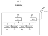
- the information terminal 21 includes a CPU 22, a storage section 23, an operation input section 24, a display section 25, an interface 26, and a communication section 27, which are connected to each other via a bus. ing.
- the CPU 22 (Central Processing Unit) is a main processor that performs predetermined processing.
- the CPU 22 is used as a processor, but any other type of semiconductor device may be used as long as it is capable of executing predetermined processing.
- the storage unit 23 can be configured using a main storage unit and an auxiliary storage unit.
- the main storage section temporarily stores data during data processing by the CPU 22, and can be configured using, for example, RAM (Random Access Memory).
- the auxiliary storage unit stores data such as programs that perform predetermined processing, and can be configured using, for example, a ROM (Read Only Memory).
- the operation input unit 24 is a device through which the user of the information terminal 21 (for example, the worker U) inputs information, and is configured using buttons, a keyboard, a mouse, a touch panel, etc. as appropriate.
- the display unit 25 is used to present data, and is configured using an appropriate output device such as a display.
- the interface 26 is used for data input/output with the terahertz wave imaging device 31.
- the information terminal 21 is connected via the interface 26 to the terahertz wave imaging device 31 wirelessly or by wire.
- the communication unit 27 is used for inputting and outputting data to and from the infrastructure database 11.
- the information terminal 21 can communicate with the base station 7 and its repeater via the communication unit 27 and antenna 28. This allows the information terminal 21 to access the infrastructure database 11 via the Internet 8.
- the information terminal 21 can be a smartphone, for example.
- the information terminal 21 may be another device (for example, a personal computer).
- the information terminal 21 can access the infrastructure database 11, and appropriate changes such as omitting the antenna 28 may be made depending on the mode of communication, for example.
- the image data of the two-dimensional code acquired by the terahertz wave imaging device 31 is output to the information terminal 21.
- the information terminal 21 then performs data processing using this image data and acquires the information stored in the two-dimensional code.
- the terahertz wave imaging device 31 only needs to be able to obtain image data that allows the shape of the two-dimensional code to be recognized, and the format of the image data that the terahertz wave imaging device 31 obtains is not particularly limited.
- the terahertz wave imaging device 31 may acquire image data of a two-dimensional code based on distance values, or may acquire image data that indicates the code portion and background portion of the two-dimensional code in binary values.
- the terahertz wave imaging device 31 is a device that can irradiate an object with emitted terahertz waves and acquire information regarding the internal state of the object through data processing based on reflected waves.
- the terahertz wave transmitted through the external structure 5b of the facility is reflected by the code portion of the two-dimensional code plate 12.
- the terahertz wave imaging device 31 acquires image data of the two-dimensional code based on the reflected wave reflected by the code section and returned.
- the terahertz wave imaging device 31 includes an internal measurement section 34, a scan mirror 39, a CPU 51, a storage section 52, It includes an operation input section 53, a display section 54, and an interface 55.
- the internal measuring section 34 is used to measure the inside (inside) of an object, and includes a terahertz wave transmitting section 35, a terahertz wave receiving section 36, a condensing lens (37a, 37b), and a half mirror 38. Be prepared.
- the terahertz wave transmitter 35 is a device that transmits terahertz waves, and in this embodiment, measurements are performed using terahertz waves with a frequency of 0.1 to 10 THz.
- the terahertz wave receiving unit 36 is a device that detects reflected waves (terahertz waves) reflected from an object.
- the condensing lenses (37a, 37b) condense the terahertz waves and convert them into higher density light.
- the condenser lens 37a condenses the terahertz wave transmitted by the terahertz wave transmitter 35.
- the condensing lens 37b condenses the terahertz wave that is incident on the terahertz wave receiving section 36.
- the half mirror 38 is configured to separate the transmitted terahertz wave and the received terahertz wave.
- the half mirror 38 is configured to transmit the terahertz wave transmitted by the terahertz wave transmitter 35 and reflect the terahertz wave received by the terahertz wave receiver 36. More specifically, the half mirror 38 separates the terahertz wave transmitted from the terahertz wave transmitter 35 and traveling along the path A into a path B toward a scan mirror 39, which will be described later, and a path C, which is different from the path B. It is something that advances the process.
- the half mirror 38 separates the terahertz waves reflected by an object, received via the scan mirror 39, and passed through the path B into a path A and a path D different from the path A.
- the terahertz wave traveling along the path D is received by the terahertz wave receiving section 36.
- the terahertz wave traveling along path C is a terahertz wave that is not used for measurement, it is possible to place anti-reflection treated members, radio wave absorbing members, etc. on the traveling direction side of the terahertz wave traveling along path C. , it is preferable to take measures to suppress the influence of reflected waves of terahertz waves traveling along path C.
- the scan mirror 39 is a mirror that irradiates the object with light from the internal measuring section 34 when scanning the object.
- the scan mirror 39 is provided so that it can rotate using a motor (not shown) controlled by the CPU 51 as a drive source during scanning. Note that the number of scan mirrors 39 is not particularly limited, but in this embodiment, it is one.
- the CPU 51 executes a predetermined program to perform operation control processing of the internal measurement unit 34, scan mirror 39, etc., and data processing.
- the CPU 51 is used as a processor, but it may be a main body that executes predetermined processing, and other semiconductor devices may also be used.
- the storage unit 52 can be configured using a main storage unit and an auxiliary storage unit.
- the main storage unit can be configured using, for example, RAM.
- the auxiliary storage unit can be configured using, for example, an HDD (Hard Disk Drive) or an SSD (Solid State Drive), and stores programs and measurements used for data processing related to image data generation and operation control of the terahertz wave imaging device 31. The data etc. obtained by
- the operation input unit 53 is used for inputting predetermined operation contents (for example, start of scanning, etc.) by a user (for example, worker U).
- the operation input section 53 can be configured as appropriate using buttons, a touch panel, or the like.
- the display unit 54 is used to display data, and is configured using an appropriate display.
- the display unit 54 may display acquired data such as image data, for example.
- the interface 55 is a configuration used for communication with the information terminal 21.
- the terahertz wave imaging device 31 is configured to be able to communicate with the information terminal 21 through wired or wireless communication, and input/output data such as output of acquired results (image data) via the interface 55. I do.
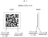
- the two-dimensional code plate 12 has a terahertz wave transmitting member layer 61 as a substrate (base), and a terahertz wave reflecting member layer 62 constituting the code portion is laminated on the terahertz wave transmitting member layer 61. be done.
- the terahertz wave transmitting member layer 61 may be made of, for example, glass or ceramic.
- the terahertz wave reflecting member layer 62 may be made of metal, for example. Gold, aluminum, copper, etc. can be used.
- the terahertz wave reflecting member layer 62 may be formed by forming a metal film on the surface of the terahertz wave transmitting member layer 61.
- the terahertz wave reflecting member layer 62 may be formed by plating.
- the terahertz wave reflecting member layer 62 may be configured three-dimensionally by pasting a metal piece corresponding to the cord portion on the surface of the terahertz wave transmitting member layer 61.
- the surface of the two-dimensional code plate 12 on which the terahertz wave reflecting layer 62 is laminated or the entire two-dimensional code plate 12 may be subjected to a surface treatment to prevent rust.
- Coating processing may be applied.
- Rust-preventing surface treatment or coating processing, that is, rust-preventing treatment can be achieved by techniques such as forming a resin film on the surface.
- the terahertz wave emitted from the terahertz wave imaging device 31 is reflected by the terahertz wave reflecting member layer 62 that constitutes the code portion, and is transmitted through the terahertz wave transmitting member layer 61. Therefore, the terahertz wave imaging device 31 can generate a captured image including a reflected image corresponding to a two-dimensional code based on the detection result of the reflection state of the terahertz wave, and can generate a two-dimensional code based on the captured image. can be recognized.
- the generation of the captured image is performed by the CPU 51 of the terahertz wave imaging device 31 executing the image generation program stored in the storage unit 52.
- the process of recognizing the two-dimensional code from the captured image may be performed by the CPU 51 of the terahertz wave imaging device 31 executing an image recognition program stored in the storage unit 52.
- the captured image is transmitted from the terahertz wave imaging device 31 to the information terminal 21 connected to the terahertz wave imaging device 31 by wire or wirelessly, and the information terminal 21 that has received the captured image
- a process for recognizing a two-dimensional code may also be performed.
- the two-dimensional code plate 12 is stored inside the infrastructure, and is imaged by the terahertz wave imaging device 31 through the external structure 5b of the infrastructure such as concrete. Therefore, direct adhesion of dust and dirt to the two-dimensional code plate 12 due to the outside air environment is unlikely to occur. Further, even if dust or dirt adheres to the external structure 5b of the infrastructure due to the outside air environment, the influence on imaging by the terahertz wave imaging device 31 is slight. Therefore, compared to a method of imaging a two-dimensional code installed on the surface of an external infrastructure structure using visible light or infrared rays, this method has an advantage in that it is less susceptible to the adhesion of dust and dirt caused by the outside air environment. As a result, information can be appropriately acquired from the infrastructure.
- Infrastructure inspections are often conducted at intervals of several years, so when a two-dimensional code is installed on the surface of the infrastructure external structure 5b, dust and dirt may accumulate on the surface of the two-dimensional code for several years. It is not easy to keep this from happening, and the surface of the two-dimensional code must be cleaned during imaging.
- the two-dimensional code plate 12 is stored inside the infrastructure, and the terahertz wave imaging device 31 transmits an image through the external structure 5b of the infrastructure such as concrete. There is no need to clean the surface of the structure 5b, and infrastructure inspections and the like can be performed at lower cost.
- the two-dimensional code plate 12 shown in FIG. 5 is a modified example of the two-dimensional code plate shown in FIG. 4.
- the configuration of the two-dimensional code plate 12 shown in FIG. 4 differs in that an electromagnetic wave absorbing member layer 63 is newly provided on the surface opposite to the terahertz wave transmitting member layer 61 and the terahertz wave reflecting member layer 62. .
- Other configurations and the like are the same as those in FIG. 4, so repeated explanation will be omitted.
- metal members such as reinforcing bars may be placed on the back side of the two-dimensional code plate 12 when viewed from the operator.
- the terahertz wave imaging device 31 of this embodiment can generate two-dimensional captured images for each depth, even if a metal member is placed on the back side of the transmission surface of the terahertz wave transmission member layer 61, it is possible to generate a two-dimensional code. Recognition is possible. However, there is a possibility that the reflected light of the terahertz wave by a metal member or the like placed on the back side of the transmission surface of the terahertz wave transmission member layer 61 may affect the recognition accuracy of the two-dimensional code.
- an electromagnetic wave absorbing member layer 63 capable of absorbing terahertz waves is provided on the back side of the terahertz wave transmitting member layer 61 when viewed from the operator, so that the back surface of the two-dimensional code plate 12 is reinforced with reinforcing bars. Even if a metal member such as the like is arranged, the configuration is such that the terahertz waves transmitted from the terahertz wave imaging device 31 do not reach the metal member or the like. Thereby, it is possible to prevent the occurrence of reflected light of the terahertz wave by the metal member, etc., and it is possible to prevent the recognition accuracy of the two-dimensional code from decreasing.
- the two-dimensional code plate 12 may be formed by pasting or coating the electromagnetic wave absorbing member layer 63 using the terahertz wave transmitting member layer 61 as a substrate. Further, for example, for supporting the electromagnetic wave absorbing member layer 63, a substrate different from the electromagnetic wave absorbing member layer 63 may be provided inside the infrastructure. In this case, it is desirable that the other substrate be placed on the side farther from the terahertz wave transmitting member layer 61 than the electromagnetic wave absorbing member layer 63 (on the back side when viewed from the operator).
- FIG. 6 shows an example of facility medical record information acquisition processing, and more specifically, transmission of a facility medical record information acquisition request from the information terminal 21 to the infrastructure database 11, and transmission of facility medical record information from the infrastructure database 11 to the information terminal 21. This is an example of sending .
- facility chart information includes, for example, facility identification number, facility manager, facility name, route name, year of construction, year of inspection, specific details of damage, details of emergency measures, and after emergency measures.
- This information stores information such as permanent measures and summarizes information regarding facilities.
- the infrastructure database 11 manages various data of the facility 5 specified by the facility identification number in association with the facility identification number (that is, information unique to the facility 5).
- the facility medical record information may also store other information regarding the facility, such as drawings and materials from the construction stage to the maintenance management stage.
- the information on the infrastructure DB address (IP address of the infrastructure database 11) and the facility identification number (identification information) included in the facility medical record information acquisition request are stored in the two-dimensional code described in this embodiment. , can be obtained from the two-dimensional code. That is, by capturing an image of a two-dimensional code stored in the infrastructure of a specific facility using the terahertz wave imaging device 31 and recognizing the two-dimensional code, a facility identification number that uniquely identifies the facility and the facility medical record of the facility are obtained. It is possible to acquire address information that is an access destination of the infrastructure database 11 that manages information. Using this information, the information terminal 21 can transmit a facility medical record information acquisition request and easily search and acquire facility medical record information of a desired facility from the infrastructure database 11. Note that the facility medical record information acquisition request may include various types of authentication information, and appropriate authentication processing may be performed. The infrastructure database 11 may then transmit the facility medical record information based on the result of the authentication process.
- the information stored in the facility medical record information is preset with information such as "cannot be updated”, “cannot be updated from an information terminal", and “can be updated from an information terminal”. . Therefore, the facility medical record information of the facility 5 acquired from the infrastructure database 11 is categorized into information such as "update not possible”, “updating not possible from an information terminal", and "updating possible from an information terminal”.
- the information terminal 21 newly updates the information "can be updated from the information terminal" among the facility medical record information of the facility 5 acquired from the infrastructure database 11 through the operation of the worker U etc. via the operation input unit 24. Generate information.
- the updated information is included in the facility chart update information, and by transmitting the facility chart update information to the infrastructure database 11, the facility chart information managed by the infrastructure database 11 can be updated.
- the worker U of the facility 5 can update appropriate information and update the facility chart information in the infrastructure database 11, for example, at the timing of finishing work at the facility 5.
- the facility identification number is information that cannot be updated. This number is associated with the two-dimensional code of the two-dimensional code plate 12, which is hardware, and cannot be updated from the information terminal 21 used by the worker U or other information terminals 21. Not allowed.
- the two-dimensional code of the two-dimensional code plate 12 of this embodiment cannot be easily rewritten, and also cannot be easily rearranged because it is stored within an infrastructure structure. Therefore, by providing at least one non-updatable identification number that permanently indicates the correspondence relationship, it is possible to uniquely identify the two-dimensional code stored within the infrastructure of the facility 5. That is, this can be a facility identification number that can uniquely identify the facility 5 in question.
- Vibrations are transmitted to infrastructure such as bridges due to vehicle traffic, earthquakes, etc. Therefore, it is necessary to take measures to prevent the two-dimensional code plate 12 from being damaged by such vibrations.
- FIG. It is configured to incorporate a two-dimensional code plate holder 72 containing the dimensional code plate 12.
- the two-dimensional code plate holder 72 may be configured to have the shape of a rectangular parallelepiped box, for example.
- the material may be any material as long as it has elasticity to the extent that it will not be damaged by strain caused by vibration or deformation in the external structure 5b, such as concrete of infrastructure such as a bridge, and that allows terahertz waves to pass through.
- the two-dimensional code plate holder 72 may be made of resin, elastomer, or the like.
- the entire two-dimensional code plate holder 72 may be made of an elastomer with a small elastic modulus.
- the two-dimensional code plate holder 72 is configured such that the flat parts of the two-dimensional code plate holder 72 are made of resin with a high elastic modulus, and the parts that join these flat parts are made of elastomer or the like with a low elastic modulus. You can. In this case, it is possible to reduce damage due to distortion caused by vibration or deformation in the external structure 5b, such as concrete of infrastructure such as a bridge, while maintaining the strength of the planar portion.
- the two-dimensional code plate 12 is directly fixed to an external structure 5b such as concrete of infrastructure such as a bridge with bolts or screws, the two-dimensional code plate Although there is a possibility that the plate 12 may be damaged, the possibility of damage to the two-dimensional code plate 12 can be reduced by creating a double structure with a two-dimensional code plate holder 72 as shown in FIG. can.
- the two-dimensional code plate 12 is surrounded and held by a buffer member 73 within the two-dimensional code plate holder 72.
- the two-dimensional code plate 12 can be held within the two-dimensional code plate holder 72 without being fixed with bolts, screws, etc., and vibrations in the external structure 5b such as concrete of infrastructure such as a bridge can be avoided. This makes it possible to reduce damage caused by distortion caused by deformation.
- the buffer member 73 may be made of an elastomer with a small elastic modulus.
- a buffer member 73 configured by storing a large amount of fine elastic members in a bag may be used. In this case, it becomes possible to absorb vibrations and strains in the external structure 5b such as concrete of infrastructure such as a bridge by moving the elastic member within the buffer member.
- the two-dimensional code plate 12 is not positioned relative to the external structure 5b such as concrete of infrastructure such as a bridge. However, the two-dimensional code plate 12 does not need to be positioned relative to the external structure 5b in order to perform its function. Depending on the type of two-dimensional code, the recognizable angle in the imaging direction is sufficiently wide. In such a case, even if the attitude of the two-dimensional code plate 12 changes over time due to the accumulation of vibrations over many years, the two-dimensional code recognition process can be performed suitably. In the first place, the imaging of the two-dimensional code plate 12 by the terahertz wave imaging device 31 according to the present embodiment is not necessarily performed from a position directly facing the two-dimensional code plate 12. It is not necessary to accurately fix the attitude of the two-dimensional code plate at a predetermined angle with respect to the external structure 5b.
- a placement display section (not shown) indicating the position where the two-dimensional code plate 12 is buried may be provided in the infrastructure.
- the operator U or the like can grasp the buried position of the two-dimensional code plate 12 using the layout display section as a clue, and can scan it with the terahertz wave imaging device 31.
- the arrangement display section is not particularly limited as long as it can indicate the position of the two-dimensional code plate 12.
- the arrangement display portion may be, for example, a concave portion, a convex portion, a mark, etc. formed on the external structure 5b.
- the recesses, protrusions, marks, etc. may be formed on the external structure 5b so as to directly face the two-dimensional code plate, for example.
- the terahertz wave imaging device 31 and the information terminal 21 can be used for the facility structure that stores the two-dimensional code. , it is possible to realize facility identification processing that is less susceptible to the adhesion of dust and dirt due to the outside air environment. Moreover, according to these, it is possible to realize a facility medical record information acquisition process and a facility medical record information update process that are less susceptible to the adhesion of dust and dirt due to the outside air environment. That is, according to the embodiment of the present invention, it is possible to realize more suitable facility medical record information management.
- the two-dimensional code plate 12 (information holding unit) to which a two-dimensional code is attached
- an information holding unit in which a two-dimensional code is attached to the base of a cube or rectangular parallelepiped may be used instead of the plate.
- the shape of the holder that holds the information holding section inside the facility 5 may be changed as appropriate.
- Output may also be achieved in other ways, such as through a storage medium such as a USB flash drive.
- the structure of the interface (26, 55) etc. may be changed as appropriate depending on the data input/output mode.
- the technology according to this embodiment makes it possible to more appropriately inspect infrastructure such as bridges, making it possible to better maintain and manage high-quality, reliable, sustainable, and strong infrastructure. This will contribute to the Sustainable Development Goals (SDGs) advocated by the United Nations, including ⁇ Building a foundation for 9 industries and technological innovation'' and ⁇ 11 Creating livable cities.''
Landscapes
- Physics & Mathematics (AREA)
- Engineering & Computer Science (AREA)
- General Physics & Mathematics (AREA)
- Theoretical Computer Science (AREA)
- Health & Medical Sciences (AREA)
- Electromagnetism (AREA)
- General Health & Medical Sciences (AREA)
- Toxicology (AREA)
- Artificial Intelligence (AREA)
- Computer Vision & Pattern Recognition (AREA)
- Investigating Or Analysing Materials By Optical Means (AREA)
Abstract
前記の情報管理システムは、情報保持部と、サーバと、を備えているシステムである。ここで、前記の情報保持部には、施設の情報を格納する2次元コードが付与されている。前記の情報保持部は、前記の施設に埋設されている。また、前記のサーバは、前記の施設の情報を管理する。そして、前記の情報保持部は、前記の施設の外部から照射されるテラヘルツ波によって前記の2次元コードの画像データを取得することができるように配置されている。
Description
本発明は、情報管理システム、情報取得方法、情報管理方法、および、2次元コードプレートに関する。
橋梁等のインフラ構造物のように、定期的な点検が必要とされる施設のデータ管理に関する技術が知られている。特許文献1には、この種の技術が開示されている。
施設の情報が該施設に付与され、表示された該情報を取得し、該情報を基に施設のデータを取り扱うことが考えられる。しかしながら、年月の経過等により、付与した施設の情報が読めなくなり、施設から情報を取得できなくなる場合があると考えられた。
そこで、本発明は、施設からの情報のより適切な取得を可能とし、この情報に基づくデータ管理をより適切に行うことに寄与することを目的とする。
本発明の第1の態様によれば、下記の情報管理システムが提供される。この情報管理システムは、情報保持部と、サーバと、を備える。情報保持部は、施設の情報を格納する2次元コードが付与され、施設に埋設されており、施設の外部から照射されるテラヘルツ波により2次元コードの画像データを取得可能に配置されている。サーバは、施設の情報を管理する。
本発明の第2の態様によれば、下記の情報取得方法が提供される。この情報取得方法は、走査装置を用いて行う方法である。走査装置は、施設の内部にテラヘルツ波を照射し、施設の情報を格納する2次元コードを走査することで、2次元コードの画像データを取得する。
本発明の第3の態様によれば、テラヘルツ波を反射する2次元コードのコード部を構成する層が基部に形成されている2次元コードプレートが提供される。
また、本発明によれば、上記の情報取得方法を用いた情報管理方法が提供される。
本発明によれば、施設からの情報のより適切な取得を可能とし、この情報に基づくデータ管理をより適切に行うことに寄与することができる。なお、上記した以外の課題、構成および効果は、以下の発明を実施するための形態の説明により明らかにされる。
以下、図面を参照して本発明の実施形態を説明する。実施形態は、本発明を説明するための例示であって、説明の明確化のため、適宜、省略および簡略化がなされている。本発明は、他の種々の形態でも実施することが可能である。特に限定しない限り、各構成要素は単数でも複数でも構わない。
図面において示す各構成要素の位置、大きさ、形状、範囲などは、発明の理解を容易にするため、実際の位置、大きさ、形状、範囲などを表していない場合がある。このため、本発明は、必ずしも、図面に開示された位置、大きさ、形状、範囲などに限定されない。
識別情報について説明する際に、「識別情報」、「識別子」、「名」、「ID」、「番号」等の表現を用いるが、これらについてはお互いに置換が可能である。
同一あるいは同様の機能を有する構成要素が複数ある場合には、同一の符号に異なる添字を付して説明する場合がある。また、これらの複数の構成要素を区別する必要がない場合には、添字を省略して説明する場合がある。
実施形態において、プログラムを実行して行う処理について説明する場合がある。ここで、計算機は、プロセッサ(例えばCPU、GPU)によりプログラムを実行し、記憶資源(例えばメモリ)やインターフェースデバイス(例えば通信ポート)等を用いながら、プログラムで定められた処理を行う。そのため、プログラムを実行して行う処理の主体を、プロセッサとしてもよい。同様に、プログラムを実行して行う処理の主体が、プロセッサを有するコントローラ、装置、システム、計算機等であってもよい。
プログラムは、プログラムソースから計算機にインストールされてもよい。プログラムソースは、例えば、プログラム配布サーバまたは計算機が読み取り可能な記憶メディアであってもよい。プログラムソースがプログラム配布サーバの場合、プログラム配布サーバはプロセッサと配布対象のプログラムを記憶する記憶資源を含み、プログラム配布サーバのプロセッサが配布対象のプログラムを他の計算機に配布してもよい。また、実施形態において、2以上のプログラムが1つのプログラムとして実現されてもよいし、1つのプログラムが2以上のプログラムとして実現されてもよい。
図面において示す各構成要素の位置、大きさ、形状、範囲などは、発明の理解を容易にするため、実際の位置、大きさ、形状、範囲などを表していない場合がある。このため、本発明は、必ずしも、図面に開示された位置、大きさ、形状、範囲などに限定されない。
識別情報について説明する際に、「識別情報」、「識別子」、「名」、「ID」、「番号」等の表現を用いるが、これらについてはお互いに置換が可能である。
同一あるいは同様の機能を有する構成要素が複数ある場合には、同一の符号に異なる添字を付して説明する場合がある。また、これらの複数の構成要素を区別する必要がない場合には、添字を省略して説明する場合がある。
実施形態において、プログラムを実行して行う処理について説明する場合がある。ここで、計算機は、プロセッサ(例えばCPU、GPU)によりプログラムを実行し、記憶資源(例えばメモリ)やインターフェースデバイス(例えば通信ポート)等を用いながら、プログラムで定められた処理を行う。そのため、プログラムを実行して行う処理の主体を、プロセッサとしてもよい。同様に、プログラムを実行して行う処理の主体が、プロセッサを有するコントローラ、装置、システム、計算機等であってもよい。
プログラムは、プログラムソースから計算機にインストールされてもよい。プログラムソースは、例えば、プログラム配布サーバまたは計算機が読み取り可能な記憶メディアであってもよい。プログラムソースがプログラム配布サーバの場合、プログラム配布サーバはプロセッサと配布対象のプログラムを記憶する記憶資源を含み、プログラム配布サーバのプロセッサが配布対象のプログラムを他の計算機に配布してもよい。また、実施形態において、2以上のプログラムが1つのプログラムとして実現されてもよいし、1つのプログラムが2以上のプログラムとして実現されてもよい。
先ず、図1を参照しながら、情報管理システムの概要を説明する。情報管理システムは、施設5の情報を管理するシステムであり、サーバに構築されるインフラデータベース11と、2次元コードプレート12(情報保持部)と、を備える。このシステムにおいて、インフラデータベース11は、施設5の情報を蓄積して管理し、基地局7及びインターネット8を介して、情報端末21と通信可能とされている。2次元コードプレート12は、コード部を含む2次元コードが付与されたプレートであり、2次元コードには、インフラデータベース11で管理する情報の一部と共通する情報が格納される。なお、インフラデータベース11で管理する施設5の情報の例、2次元コードに格納される情報の例、および、2次元コードプレート12の具体的な構造例については後で詳しく説明する。施設5は、インフラストラクチャー(いわゆる、インフラ)であり、例えば、鉄鋼を用いて形成される内部構造5aと、コンクリートを用いて形成され、内部構造5aを覆う外部構造5bと、を有する。このようなインフラの例としては、橋梁、トンネル、シェッド、大型カルバート、横断歩道、橋門型標識等が挙げられる。
2次元コードプレート12は、テラヘルツ波による走査を行うテラヘルツ波撮像装置31(走査装置)で施設5の外部から走査可能となるように、施設5に埋設される。例えば、施設5の点検作業時において、作業者U(ユーザ)がテラヘルツ波撮像装置31を用いて2次元コードの情報を取得する。そして、作業者Uは、取得した情報および情報端末21を利用して、インフラデータベース11上の施設5の情報を取得したり、インフラデータベース11上の施設5の情報を更新することができる。なお、テラヘルツ波は、物体の内部の情報の取得に用いられている。
次に、図2を参照しながら、情報端末のハードウェア構成の一例について説明する。図2に示すように、情報端末21は、CPU22と、記憶部23と、操作入力部24と、表示部25と、インタフェース26と、通信部27と、を備え、バスを介してそれぞれ接続されている。
CPU22(Central Processing Unit)は、所定の処理を行う主体となるプロセッサである。本実施形態では、CPU22がプロセッサとして用いられるが、所定の処理を実行することができればよく、他の種類の半導体デバイスであってもよい。
記憶部23は、主記憶部と、補助記憶部と、を用いて構成することができる。主記憶部は、CPU22によるデータ処理時においてデータを一時的に記憶し、例えば、RAM(Random Access Memory)を用いて構成することができる。補助記憶部は、所定の処理を行うプログラム等のデータを格納し、例えば、ROM(Read Only Memory)を用いて構成することができる。
操作入力部24は、情報端末21のユーザ(例えば、作業者U)が情報を入力する装置であり、ボタン、キーボード、マウス、タッチパネル等を適宜に用いて構成される。表示部25は、データの提示に用いられ、ディスプレイ等の適宜の出力装置を用いて構成される。
インタフェース26は、テラヘルツ波撮像装置31とのデータの入出力に用いられる。本実施形態では、情報端末21は、インタフェース26を介して、テラヘルツ波撮像装置31に無線または有線で接続される。通信部27は、インフラデータベース11とのデータの入出力に用いられる。本実施形態では、情報端末21は、通信部27およびアンテナ28を介して、基地局7やその中継器と通信可能である。これによって、情報端末21は、インターネット8を経由してインフラデータベース11にアクセスできる。
なお、情報端末21は、一例として、スマートフォンとすることができる。ただし、情報端末21は他の装置(例えば、パーソナルコンピュータ)とされてもよい。また、情報端末21がインフラデータベース11にアクセスできればよく、例えば、通信の態様に応じてアンテナ28を省略する等の適宜の変更が行われてもよい。
本実施形態では、テラヘルツ波撮像装置31により取得された2次元コードの画像データが情報端末21に出力される。そして、情報端末21は、この画像データを用いてデータ処理を行い、2次元コードに格納された情報を取得する。なお、テラヘルツ波撮像装置31は、2次元コードの形状を認識可能な画像データを取得することができればよく、テラヘルツ波撮像装置31が取得する画像データの形式は、特に限定されない。テラヘルツ波撮像装置31は、例えば、距離値に基づく2次元コードの画像データを取得してもよいし、2次元コードにおけるコード部と背景部を2値で示す画像データを取得してもよい。
次に、図3を参照しながら、テラヘルツ波撮像装置の構成の一例について説明する。テラヘルツ波撮像装置31は、発信したテラヘルツ波を物体に照射し、反射波に基づくデータ処理により、物体の内部の状態に関する情報を取得することができる装置である。本実施形態では、施設の外部構造5bを透過したテラヘルツ波が、2次元コードプレート12のコード部で反射する。そして、テラヘルツ波撮像装置31は、コード部で反射して戻る反射波に基づいて、2次元コードの画像データを取得する。
図3に示すように、テラヘルツ波撮像装置31は、光が通過する開口部32が形成された筐体33の内部に、内部測定部34と、スキャンミラー39と、CPU51と、記憶部52、操作入力部53、表示部54、インタフェース55と、を備える。
内部測定部34は、物体の内側(内部)を測定することに用いられ、テラヘルツ波発信部35と、テラヘルツ波受信部36と、集光レンズ(37a、37b)と、ハーフミラー38と、を備える。
テラヘルツ波発信部35は、テラヘルツ波を発信する装置であり、本実施形態では、周波数が0.1~10THzのテラヘルツ波を用いた測定が行われる。
テラヘルツ波受信部36は、物体から反射する反射波(テラヘルツ波)を検出する装置である。
集光レンズ(37a、37b)は、テラヘルツ波を集光し、より密度の高い光に変換する。集光レンズ37aは、テラヘルツ波発信部35が発信するテラヘルツ波を集光する。集光レンズ37bは、テラヘルツ波受信部36に入射するテラヘルツ波を集光する。
ハーフミラー38は、発信するテラヘルツ波と受信するテラヘルツ波を分ける構成である。本実施形態では、ハーフミラー38は、テラヘルツ波発信部35で発信したテラヘルツ波を透過し、テラヘルツ波受信部36で受信するテラヘルツ波を反射する構成である。より詳細には、ハーフミラー38は、テラヘルツ波発信部35から発信され経路Aを進行するテラヘルツ波については、後述するスキャンミラー39に向かう経路Bと、経路Bとは異なる経路Cに分離して進行させるものである。また、ハーフミラー38は、物体で反射されたテラヘルツ波であって、スキャンミラー39を介して受信され、経路Bを経たテラヘルツ波については、経路Aと経路Aとは異なる経路Dに分離して進行させるものであり、経路Dを進行するテラヘルツ波がテラヘルツ波受信部36で受信されることとなる。ここで、経路Cを進行するテラヘルツ波は測定に使用されないテラヘルツ波であるため、経路Cを進行するテラヘルツ波の進行方向側に反射防止加工を施した部材や電波吸収部材等を配置することで、経路Cを進行するテラヘルツ波の反射波の影響を抑える対策をすることが好ましい。
スキャンミラー39は、物体を走査する際に、内部測定部34からの光を物体に照射するミラーである。スキャンミラー39は、走査時において、CPU51が制御するモータ(不図示)を駆動源として回転することができるように設けられる。なお、スキャンミラー39の枚数は特に限定されないが、本実施形態では、1枚とされている。
CPU51は、所定のプログラムを実行して、内部測定部34、スキャンミラー39等の動作制御処理、および、データ処理を行う。本実施形態では、CPU51がプロセッサとして用いられているが、所定の処理を実行する主体であればよく、他の半導体デバイスが用いられてもよい。
記憶部52は、主記憶部と、補助記憶部と、を用いて構成することができる。主記憶部は、例えば、RAMを用いて構成することができる。補助記憶部は、例えば、HDD(Hard Disk Drive)やSSD(Solid State Drive)を用いて構成することができ、画像データの生成に関するデータ処理やテラヘルツ波撮像装置31の動作制御に用いるプログラム、測定により取得したデータ等を記憶する。
操作入力部53は、ユーザ(例えば、作業者U)による所定の操作内容(例えば、走査の開始等)の入力に用いられる。操作入力部53は、ボタンやタッチパネル等を用いて適宜に構成することができる。
表示部54は、データの表示に用いられ、適宜のディスプレイを用いて構成される。表示部54には、一例として、画像データ等の取得するデータが表示されてもよい。
インタフェース55は、情報端末21との通信に用いる構成である。本実施形態では、テラヘルツ波撮像装置31は、有線通信または無線通信により、情報端末21と通信可能に構成され、インタフェース55を介して、取得した結果(画像データ)の出力等のデータの入出力を行う。
次に、図4を参照しながら、2次元コードプレートの具体的な構成の一例について説明する。図4に示すように、2次元コードプレート12は、テラヘルツ波透過部材層61を基板(基部)とし、テラヘルツ波透過部材層61に、コード部を構成するテラヘルツ波反射部材層62が積層され構成される。
ここで、テラヘルツ波透過部材層61は例えば、ガラスまたはセラミックなどにより構成すればよい。
テラヘルツ波反射部材層62は、例えば、金属により構成すればよい。金、アルミニウム、銅などを用いることが可能である。テラヘルツ波反射部材層62は金属膜をテラヘルツ波透過部材層61の表面に成膜してもよい。また、テラヘルツ波反射部材層62がめっき処理により形成されてもよい。また、テラヘルツ波反射部材層62は、テラヘルツ波透過部材層61の表面にコード部に対応した金属片を貼り付けて立体的に構成してもよい。
なお、テラヘルツ波反射部材層62での金属の錆防止のため、2次元コードプレート12におけるテラヘルツ波反射部材層62を積層している面または、2次元コードプレート12全体を錆防止の表面処理やコーティング加工を施してもよい。錆防止の表面処理やコーティング加工、すなわち防錆処理は、表面に樹脂膜を形成するなどの技術で実現可能である。
テラヘルツ波撮像装置31から発信されるテラヘルツ波は、コード部を構成するテラヘルツ波反射部材層62により反射され、テラヘルツ波透過部材層61を透過する。したがって、テラヘルツ波撮像装置31は、当該テラヘルツ波の反射状態の検出結果に基づいて2次元コードに対応する反射画像を含む撮像画像を生成することができ、当該撮像画像に基づいて2次元コードを認識することできる。
なお、当該撮像画像の生成は、上記したように、テラヘルツ波撮像装置31においてCPU51が記憶部52に記憶された画像生成プログラムを実行することにより行われる。そして、撮像画像から2次元コードを認識する処理は、テラヘルツ波撮像装置31においてCPU51が記憶部52に記憶された画像認識プログラムを実行することにより行われてもよい。その一方で、テラヘルツ波撮像装置31に有線または無線で接続された情報端末21に対して、テラヘルツ波撮像装置31から撮像画像を送信し、当該撮像画像を受信した情報端末21において当該撮像画像から2次元コードを認識する処理を行ってもよい。
2次元コードプレート12はインフラ内部に格納され、テラヘルツ波撮像装置31により、コンクリートなどのインフラの外部構造5bを透過して撮像される。そのため、外気環境による2次元コードプレート12への直接の埃や汚れの付着などは生じにくい。また、外気環境によるインフラの外部構造5bへ埃や汚れの付着があったとしても、テラヘルツ波撮像装置31の撮像への影響は軽微である。よって、可視光や赤外線等で、インフラ外部構造の表面に設置された2次元コードを撮像する方式に比べ、外気環境による埃や汚れの付着の影響を受けにくい点で利点がある。その結果、インフラから情報を適切に取得することができる。
インフラ検査は数年の間隔が設定されていることが多いため、インフラ外部構造5bの表面に2次元コードを設置する場合、当該数年の間、当該2次元コードの表面に埃や汚れの付着がなされないように維持することは容易ではなく、撮像時に2次元コード表面の清掃が必要となる。本実施形態の方式のように、2次元コードプレート12をインフラ内部に格納し、テラヘルツ波撮像装置31により、コンクリートなどのインフラの外部構造5bを透過して撮像する方式は、撮像時にインフラの外部構造5bの表面の清掃は必要なく、より低コストにインフラ検査等を実行することができる。
次に、図5を参照しながら、2次元コードプレートの他の構成例について説明する。図5に示す2次元コードプレート12は、図4に示す2次元コードプレートの変形構成例である。図4の2次元コードプレート12の構成に対し、テラヘルツ波透過部材層61に対して、テラヘルツ波反射部材層62の反対側の面に、新たに電磁波吸収部材層63を設けた点で相違する。その他の構成等は、図4と同様であるため、繰り返しの説明は省略する。
インフラの内部構造5aによっては、作業者から見て2次元コードプレート12の背面に、鉄筋などの金属部材が配置されている場合がある。
本実施形態のテラヘルツ波撮像装置31は奥行毎に2次元の撮像画像を生成可能であるため、テラヘルツ波透過部材層61の透過面の背面に金属部材が配置されていても、2次元コードの認識は可能である。ただし、テラヘルツ波透過部材層61の透過面の背面に配置される金属部材等によるテラヘルツ波の反射光が2次元コードの認識精度へ影響を及ぼす可能性もある。
そこで、図5の例では、作業者から見てテラヘルツ波透過部材層61の奥側に、テラヘルツ波の吸収が可能な電磁波吸収部材層63を設けることにより、2次元コードプレート12の背面に鉄筋などの金属部材が配置されていても、テラヘルツ波撮像装置31から発信されるテラヘルツ波が当該金属部材等に到達しないように構成する。これにより、当該金属部材等によるテラヘルツ波の反射光が生じることを防ぐことができ、2次元コードの認識精度の低減を防止することができる。
なお、電磁波吸収部材層63の具体的な構成は、既存の技術を用いればよい。例えば、特開2019-75571号公報に記載の技術や、国際公開番号WO2019/017471号公報に記載の技術などを用いればよい。これらの技術では、ミリ波以上の周波数の波を好適に吸収することができる。
テラヘルツ波透過部材層61を基板として、電磁波吸収部材層63を貼り付けまたは塗布にて、2次元コードプレート12が形成されてもよい。また、例えば電磁波吸収部材層63の支持等のために、電磁波吸収部材層63とは別の基板をインフラ内部に設けてもよい。この場合、当該別の基板は、電磁波吸収部材層63よりもテラヘルツ波透過部材層61から離れた側(作業者から見て奥側)に配置するのが望ましい。
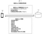
次に、図6を参照しながら、インフラデータベースにおいて管理される情報を取得する処理の一例について説明する。図6は、施設カルテ情報取得処理の例であり、より具体的には、情報端末21からインフラデータベース11への施設カルテ情報取得リクエストの送信と、インフラデータベース11から情報端末21への施設カルテ情報の送信の例である。
ここで、施設カルテ情報(施設情報)は、例えば、施設識別番号、施設の管理者、施設名、路線名、建設年度、点検実施年度、損傷の具体的内容、緊急措置内容、緊急措置後の恒久的な措置、等の情報を格納し、施設に関する情報をまとめた情報である。インフラデータベース11は、施設識別番号(すなわち、施設5に固有の情報)に関連付けて、施設識別番号により特定される施設5の様々なデータを管理する。なお、施設カルテ情報は、建設から維持管理段階までの図面や資料等、施設に関する他の情報を格納してもよい。
そして、施設カルテ情報取得リクエストに含まれる、インフラDBアドレス(インフラデータベース11のIPアドレス)の情報と、施設識別番号(識別情報)は、本実施形態で説明された2次元コードに格納されており、当該2次元コードから取得可能である。すなわち、特定施設のインフラ内に格納された2次元コードをテラヘルツ波撮像装置31により撮像し、2次元コードの認識を行うことで、施設を一意に特定する施設識別番号と、当該施設の施設カルテ情報を管理するインフラデータベース11のアクセス先であるアドレス情報を取得することが可能である。情報端末21は、これらの情報を用いて、施設カルテ情報取得リクエストを送信し、インフラデータベース11から所望の施設の施設カルテ情報を容易に検索して取得することが可能である。なお、施設カルテ情報取得リクエストには、各種の認証情報が含まれてもよく、適宜の認証処理が行われてもよい。そして、インフラデータベース11は、認証処理の結果に基づいて、施設カルテ情報を送信してもよい。
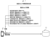
次に、図7を参照しながら、施設カルテ情報の更新処理の一例について説明する。図7に示すように、施設カルテ情報が格納する情報には、「更新不可」の情報、「情報端末からは更新不可」の情報、「情報端末から更新可」の情報が予め設定されている。従って、インフラデータベース11から取得した施設5の施設カルテ情報には、「更新不可」の情報、「情報端末からは更新不可」の情報、「情報端末から更新可」の情報などの分類がある。
情報端末21は、操作入力部24を介した作業者U等の操作により、インフラデータベース11から取得した施設5の施設カルテ情報のうち、「情報端末から更新可」の情報について、新たに更新した情報を生成する。当該更新した情報は施設カルテ更新情報に含められ、当該施設カルテ更新情報をインフラデータベース11へ送信することにより、インフラデータベース11で管理する施設カルテ情報の更新が可能である。施設5の作業者Uは、例えば施設5の作業終了のタイミングで適宜の情報を更新し、インフラデータベース11の施設カルテ情報を更新することができる。
なお、「情報端末からは更新不可」の情報については、システムの管理者権限などを有する上位端末からの更新は可能とするが、作業者U等が使用する情報端末21からの更新は不可とした情報である。すなわち、上位端末を用いたユーザによる更新は可能であるが、情報端末21を用いたユーザ(例えば、作業者U)による更新は不可である。
また、施設カルテ情報のうち、施設識別番号は「更新不可」の情報である。この番号は、ハードウェアである2次元コードプレート12の2次元コードと対応付けられた番号であり、作業者U等が使用する情報端末21からの更新も、その他の情報端末21からの更新も不可とする。本実施形態の2次元コードプレート12の2次元コードは容易に書き換えることはできないうえ、インフラ構造内に格納されているため容易に配置替えをすることができない。よって、恒久的に対応関係が示される更新不可の識別番号を少なくとも1つ存在させることにより、施設5のインフラ構造内に格納されている2次元コードを一意に特定することができる。すなわち、これは当該施設5を一意に特定することができる施設識別番号となりえる。
次に、図8を参照しながら、2次元コードプレートのインフラ構造内での保持方法の一例について説明する。
橋梁等のインフラは、車両の通行や地震などにより振動が伝達される。従って、2次元コードプレート12がこのような振動では損傷しないように、工夫が必要である。
そこで、本実施形態では、図8に示すように、コンクリート等の外部構造5bに2次元コードプレート12を収める2次元コードプレートホルダ72を格納する保持空間71を形成し、その保持空間71に2次元コードプレート12を収めた2次元コードプレートホルダ72を組み込むように構成している。
2次元コードプレートホルダ72は、例えば直方体の箱の形状を有するように構成すればよい。その材質は、橋梁等のインフラのコンクリートなどの外部構造5bにおける振動や変形に起因する歪で破損しない程度の弾性があり、テラヘルツ波が透過する材質であればよい。2次元コードプレートホルダ72は、樹脂やエラストマーなどで構成すればよい。弾性率の小さいエラストマーで2次元コードプレートホルダ72全体を構成してもよい。このように弾性率の小さい材質の材料で2次元コードプレートホルダ72を構成することにより、橋梁等インフラのコンクリートなどの外部構造5bにおける振動や変形に起因する歪による破損を低減することが可能となる。
また、2次元コードプレートホルダ72の平面部分は、弾性率の大きい樹脂を用い、これらの平面部分をジョイントする部分だけ弾性率の小さいエラストマーなどを用いるように、2次元コードプレートホルダ72が構成されてもよい。この場合、平面部分の強度を保ちつつ、橋梁等インフラのコンクリートなどの外部構造5bにおける振動や変形に起因する歪による破損を低減することが可能となる。
例えば、橋梁等のインフラのコンクリートなどの外部構造5bにボルトやネジなどにより直接2次元コードプレート12を固定すると、車両の通行や地震などの振動で生じた変形に起因する応力で、2次元コードプレート12が破損する可能性があるが、図8に示すような、2次元コードプレートホルダ72を介した2重構造にすることにより、2次元コードプレート12の破損の可能性を低減することができる。
次に、図9を参照しながら、2次元コードプレートホルダ内で2次元コードプレートを保持する方法の一例について説明する。
図9に示すように、2次元コードプレートホルダ72内で2次元コードプレート12は緩衝部材73に取り囲まれて保持される。これにより、2次元コードプレートホルダ72内でも2次元コードプレート12はボルトやネジなどを介した固定を行うことなく保持されることが可能となり、橋梁等のインフラのコンクリートなどの外部構造5bにおける振動や変形に起因する歪による破損を低減することが可能となる。
緩衝部材73は、弾性率の小さいエラストマーで構成してもよい。また、袋に細かな弾性体部材を大量に格納して構成した緩衝部材73を用いてもよい。この場合、橋梁等のインフラのコンクリートなどの外部構造5bにおける振動や歪を緩衝部材内の弾性体部材が移動することで吸収することが可能となる。
図9の保持方法では、2次元コードプレート12は、橋梁等のインフラのコンクリートなどの外部構造5bに対して位置決めされた状態にはならない。しかしながら、2次元コードプレート12はその機能を発揮するにあたり、外部構造5bに対して位置決めされた状態である必要はない。2次元コードの種類によっては、撮像方向の認識可能角度が十分に広い。このような場合、仮に長年の振動の積み重ねにより経時的に2次元コードプレート12の姿勢が変化してしまっても、2次元コードの認識処理は好適に行うことが可能である。そもそも、本実施形態にかかるテラヘルツ波撮像装置31による2次元コードプレート12の撮像は必ずしも2次元コードプレート12に正対する位置から撮像が行われるとは限らないため、橋梁等のインフラのコンクリートなどの外部構造5bに対して2次元コードプレートの姿勢を所定の角度に正確に固定しておく必要はない。
なお、2次元コードプレート12が埋設されている位置を示す配置表示部(不図示)がインフラに設けられてもよい。この場合、作業者U等は、配置表示部を手掛かりとして2次元コードプレート12が埋設されている位置を把握し、テラヘルツ波撮像装置31で走査を行うことができる。配置表示部は、2次元コードプレート12の位置を示すことができれば特に限定されない。配置表示部は、例えば、外部構造5bに形成された凹部や凸部、マーク等であってもよい。また、凹部や凸部、マーク等は、例えば、2次元コードプレートに正対するように外部構造5bに形成されてもよい。
以上説明した、本実施形態の2次元コードプレート12、インフラデータベース11を備えるシステムによれば、2次元コードを格納する施設構造に対して、テラヘルツ波撮像装置31および情報端末21それぞれを用いることで、外気環境による埃や汚れの付着の影響を受けにくい施設識別処理が実現可能である。また、これらによれば、外気環境による埃や汚れの付着の影響を受けにくい施設カルテ情報取得処理および施設カルテ情報更新処理が実現可能である。すなわち、本発明の実施形態によれば、より好適な施設カルテ情報管理を実現することが可能となる。
以上、本発明の実施形態について詳述したが、本発明は、前記の実施形態に限定されるものではなく、特許請求の範囲に記載された本発明の精神を逸脱しない範囲で、種々の設計変更を行うことができるものである。例えば、前記した実施の形態は本発明を分かりやすく説明するために詳細に説明したものであり、必ずしも説明した全ての構成を備えるものに限定されるものではない。また、ある実施形態の構成の一部を他の実施形態の構成に置き換えることが可能であり、また、ある実施形態の構成に他の実施形態の構成を加えることも可能である。さらに、各実施形態の構成の一部について、他の構成の追加・削除・置換をすることが可能である。
2次元コードが付与される2次元コードプレート12(情報保持部)について説明されたが、プレートに代えて立方体や直方体の基部に2次元コードが付与された情報保持部が用いられてもよい。また、この変更に伴って、施設5の内部で情報保持部を保持するホルダの形状が適宜に変更されてもよい。
実施形態では、テラヘルツ波撮像装置31と情報端末21が有線または無線で接続されてデータ入出力が行われる例について説明されたが、テラヘルツ波撮像装置31と情報端末21との間のデータの入出力が、USBフラッシュドライブ(USBメモリ)等の記憶媒体を介した手法など、他の手法により実現されてもよい。データの入出力の態様に応じて、インタフェース(26,55)等の構造を適宜に変更してもよい。
本実施形態に係る技術では、橋梁などのインフラをより好適に点検することが可能となり、質が高く、信頼できる、持続可能かつ強靱なインフラをより好適に維持、管理することを可能にする。これにより、国連の提唱する持続可能な開発目標(SDGs:Sustainable Development Goals)の「9産業と技術革新の基盤をつくろう」および「11住み続けられるまちづくりを」に貢献する。
11 インフラデータベース
12 2次元コードプレート
21 情報端末
31 テラヘルツ波撮像装置
12 2次元コードプレート
21 情報端末
31 テラヘルツ波撮像装置
Claims (14)
- 施設の情報を格納する2次元コードが付与され、前記施設に埋設されており、前記施設の外部から照射されるテラヘルツ波により前記2次元コードの画像データを取得可能に配置されている情報保持部と、
前記施設の情報を管理するサーバと、を備える、
ことを特徴とする情報管理システム。 - 請求項1に記載の情報管理システムであって、
前記施設は、
前記情報保持部を格納するホルダを備えており、
前記情報保持部は、
前記ホルダ内の空間に収められた状態で配置される、
ことを特徴とする情報管理システム。 - 請求項2に記載の情報管理システムであって、
前記ホルダは、
前記情報保持部を取り囲む緩衝部材を格納する、
ことを特徴とする情報管理システム。 - 請求項1に記載の情報管理システムであって、
前記施設は、
前記情報保持部が埋設されている位置を示す配置表示部を備える、
ことを特徴とする情報管理システム。 - 走査装置を用いて行う情報取得方法であって、
前記走査装置は、
施設の内部にテラヘルツ波を照射し、前記施設の情報を格納する2次元コードを走査することで、前記2次元コードの画像データを取得する、
ことを特徴とする情報取得方法。 - 請求項5に記載の情報取得方法であって、
前記2次元コードは、施設を特定する識別情報を格納する、
ことを特徴とする情報取得方法。 - 請求項6に記載の情報取得方法を用いた情報管理方法であって、
施設に関する複数の情報を格納しており、ユーザが情報端末を用いて更新可能である情報を含む施設情報を、前記識別情報ごとにサーバが管理する、
ことを特徴とする情報管理方法。 - 請求項6に記載の情報取得方法を用いた情報管理方法であって、
施設に関する複数の情報を格納しており、それぞれの情報にユーザが情報端末を用いて更新可能または更新不可の設定がされた施設情報を、前記識別情報ごとにサーバが管理する、
ことを特徴とする情報管理方法。 - 請求項5に記載の情報取得方法を用いた情報管理方法であって、
前記2次元コードの情報に含まれる施設識別番号と、
前記施設の管理者と、
前記施設の施設名と、
前記施設の路線名と、
前記施設の建設年度と、
前記施設の点検実施年度と、
前記施設の損傷の内容と、
前記施設の緊急措置内容と、
前記施設の緊急措置後の恒久的な措置と、
に関する情報を関連付けて、サーバが管理する、
ことを特徴とする情報管理方法。 - テラヘルツ波を反射する2次元コードのコード部を構成する層が基部に形成されている、
ことを特徴とする2次元コードプレート。 - 請求項10に記載の2次元コードプレートであって、
前記の2次元コードのコード部を構成する層の防錆処理が施されている、
ことを特徴とする2次元コードプレート。 - 請求項10に記載の2次元コードプレートであって、
前記2次元コードが形成されている面と反対側に、テラヘルツ波を吸収するテラヘルツ波吸収層が形成されている、
ことを特徴とする2次元コードプレート。 - 請求項10に記載の2次元コードプレートであって、
前記コード部が金属である、
ことを特徴とする2次元コードプレート。 - 請求項10に記載の2次元コードプレートであって、
前記基部は、テラヘルツ波を透過するテラヘルツ波透過層として形成されており、セラミックスまたはガラスによって形成されている、
ことを特徴とする2次元コードプレート。
Applications Claiming Priority (2)
| Application Number | Priority Date | Filing Date | Title |
|---|---|---|---|
| JP2022-111016 | 2022-07-11 | ||
| JP2022111016A JP2024009470A (ja) | 2022-07-11 | 2022-07-11 | 情報管理システム、情報取得方法、情報管理方法、および、2次元コードプレート |
Publications (1)
| Publication Number | Publication Date |
|---|---|
| WO2024014064A1 true WO2024014064A1 (ja) | 2024-01-18 |
Family
ID=89536349
Family Applications (1)
| Application Number | Title | Priority Date | Filing Date |
|---|---|---|---|
| PCT/JP2023/012074 Ceased WO2024014064A1 (ja) | 2022-07-11 | 2023-03-27 | 情報管理システム、情報取得方法、情報管理方法、および、2次元コードプレート |
Country Status (2)
| Country | Link |
|---|---|
| JP (1) | JP2024009470A (ja) |
| WO (1) | WO2024014064A1 (ja) |
Citations (9)
| Publication number | Priority date | Publication date | Assignee | Title |
|---|---|---|---|---|
| JP2003004843A (ja) * | 2001-06-25 | 2003-01-08 | Maeda Corp | 埋込型データ管理方法 |
| US20060231625A1 (en) * | 2003-03-12 | 2006-10-19 | Cumming David R | Security label which is optically read by terahertz radiation |
| JP2014118766A (ja) * | 2012-12-18 | 2014-06-30 | Mitomo Shoji Kk | 工事画像データ記録システムおよび構造物埋設用データ記録ユニット |
| JP2014229230A (ja) * | 2013-05-27 | 2014-12-08 | 株式会社エムビーエス | 対象物管理サーバ、対象物管理システム及び対象物管理方法 |
| US20150102105A1 (en) * | 2012-06-26 | 2015-04-16 | Arjowiggins Security | Item comprising a barcode with an electromagnetic signature |
| US20150170013A1 (en) * | 2013-12-14 | 2015-06-18 | Microsoft Corporation | Fabricating Information Inside Physical Objects for Imaging in the Terahertz Region |
| JP2016139351A (ja) * | 2015-01-29 | 2016-08-04 | 清水建設株式会社 | 構造物点検支援システム |
| KR20180042120A (ko) * | 2016-10-17 | 2018-04-25 | 한국전자통신연구원 | 고주파를 사용한 태깅 방법 및 장치 |
| JP2019036094A (ja) * | 2017-08-14 | 2019-03-07 | 三菱重工機械システム株式会社 | 塗装板材、自動車、検出システム、及び検出方法 |
-
2022
- 2022-07-11 JP JP2022111016A patent/JP2024009470A/ja active Pending
-
2023
- 2023-03-27 WO PCT/JP2023/012074 patent/WO2024014064A1/ja not_active Ceased
Patent Citations (9)
| Publication number | Priority date | Publication date | Assignee | Title |
|---|---|---|---|---|
| JP2003004843A (ja) * | 2001-06-25 | 2003-01-08 | Maeda Corp | 埋込型データ管理方法 |
| US20060231625A1 (en) * | 2003-03-12 | 2006-10-19 | Cumming David R | Security label which is optically read by terahertz radiation |
| US20150102105A1 (en) * | 2012-06-26 | 2015-04-16 | Arjowiggins Security | Item comprising a barcode with an electromagnetic signature |
| JP2014118766A (ja) * | 2012-12-18 | 2014-06-30 | Mitomo Shoji Kk | 工事画像データ記録システムおよび構造物埋設用データ記録ユニット |
| JP2014229230A (ja) * | 2013-05-27 | 2014-12-08 | 株式会社エムビーエス | 対象物管理サーバ、対象物管理システム及び対象物管理方法 |
| US20150170013A1 (en) * | 2013-12-14 | 2015-06-18 | Microsoft Corporation | Fabricating Information Inside Physical Objects for Imaging in the Terahertz Region |
| JP2016139351A (ja) * | 2015-01-29 | 2016-08-04 | 清水建設株式会社 | 構造物点検支援システム |
| KR20180042120A (ko) * | 2016-10-17 | 2018-04-25 | 한국전자통신연구원 | 고주파를 사용한 태깅 방법 및 장치 |
| JP2019036094A (ja) * | 2017-08-14 | 2019-03-07 | 三菱重工機械システム株式会社 | 塗装板材、自動車、検出システム、及び検出方法 |
Also Published As
| Publication number | Publication date |
|---|---|
| JP2024009470A (ja) | 2024-01-23 |
Similar Documents
| Publication | Publication Date | Title |
|---|---|---|
| Tabjula et al. | Outlier analysis for defect detection using sparse sampling in guided wave structural health monitoring | |
| Wang et al. | Automatic as-built BIM creation of precast concrete bridge deck panels using laser scan data | |
| Scaioni et al. | Photogrammetric techniques for monitoring tunnel deformation | |
| Abdelgawad et al. | Internet of things (IoT) platform for structure health monitoring | |
| Kim et al. | A mirror-aided laser scanning system for geometric quality inspection of side surfaces of precast concrete elements | |
| Xu et al. | TLS-based composite structure deformation analysis validated with laser tracker | |
| EP3407590B1 (en) | Imaging support device and imaging support method | |
| JP5857858B2 (ja) | 形状計測装置及び形状計測方法 | |
| Alipour et al. | Field deployment and laboratory evaluation of 2D digital image correlation for deflection sensing in complex environments | |
| US11113488B2 (en) | Glass panel manufacturing systems and methods | |
| Maksymenko et al. | Multilaser spot tracking technology for bridge structure displacement measuring | |
| US20190293518A1 (en) | New autonomous electro-optical system to monitor in real-time the full spatial motion (rotation and displacement) of civil structures | |
| Zhang et al. | Study on the dynamic properties of a suspended bridge using monocular digital photography to monitor the bridge dynamic deformation | |
| Kalybek et al. | Performance of camera-based vibration monitoring systems in input-output modal identification using shaker excitation | |
| Truong-Hong et al. | Using terrestrial laser scanning for dynamic bridge deflection measurement | |
| Owerko et al. | Novel approach to inspections of as-built reinforcement in incrementally launched bridges by means of computer vision-based point cloud data | |
| JP2024009470A (ja) | 情報管理システム、情報取得方法、情報管理方法、および、2次元コードプレート | |
| Qi et al. | Structural dynamic deflection measurement with range cameras | |
| Geng et al. | Analysis of electromagnetic coupling characteristics of balise transmission system based on digital twin | |
| US20150369909A1 (en) | Image sensor for large area ultrasound mapping | |
| Kim et al. | Dynamic characteristics of multi-degree-of-freedom frame systems derived from vision-based displacement measurement using consumer-grade camera video | |
| Micozzi et al. | Vision-based dynamic monitoring of a post-tensioned concrete bridge under vehicular traffic | |
| Dizaji et al. | Reframing measurement for structural health monitoring: a full-field strategy for structural identification | |
| Zhou et al. | Robust and high-precision vision system for deflection measurement of crane girder with camera shake reduction | |
| Jafari et al. | Long-term monitoring of structures through point cloud analysis |
Legal Events
| Date | Code | Title | Description |
|---|---|---|---|
| 121 | Ep: the epo has been informed by wipo that ep was designated in this application |
Ref document number: 23839243 Country of ref document: EP Kind code of ref document: A1 |
|
| NENP | Non-entry into the national phase |
Ref country code: DE |
|
| 122 | Ep: pct application non-entry in european phase |
Ref document number: 23839243 Country of ref document: EP Kind code of ref document: A1 |