WO2024013778A1 - Solar power generator for vehicle - Google Patents
Solar power generator for vehicle Download PDFInfo
- Publication number
- WO2024013778A1 WO2024013778A1 PCT/JP2022/027183 JP2022027183W WO2024013778A1 WO 2024013778 A1 WO2024013778 A1 WO 2024013778A1 JP 2022027183 W JP2022027183 W JP 2022027183W WO 2024013778 A1 WO2024013778 A1 WO 2024013778A1
- Authority
- WO
- WIPO (PCT)
- Prior art keywords
- power generation
- solar power
- vehicle
- panel
- generation device
- Prior art date
Links
- 238000010248 power generation Methods 0.000 claims abstract description 86
- 230000005611 electricity Effects 0.000 claims description 20
- 238000006243 chemical reaction Methods 0.000 claims description 7
- 238000001816 cooling Methods 0.000 claims description 3
- 230000003247 decreasing effect Effects 0.000 claims 1
- 230000015556 catabolic process Effects 0.000 abstract 1
- 238000006731 degradation reaction Methods 0.000 abstract 1
- 238000010586 diagram Methods 0.000 description 5
- 230000006866 deterioration Effects 0.000 description 3
- 230000005856 abnormality Effects 0.000 description 2
- 241000150258 Prospect Hill orthohantavirus Species 0.000 description 1
- 230000007797 corrosion Effects 0.000 description 1
- 238000005260 corrosion Methods 0.000 description 1
- 230000002542 deteriorative effect Effects 0.000 description 1
- 238000007599 discharging Methods 0.000 description 1
- 229920000218 poly(hydroxyvalerate) Polymers 0.000 description 1
- 230000000452 restraining effect Effects 0.000 description 1
- 238000010186 staining Methods 0.000 description 1
Images


Classifications
-
- B—PERFORMING OPERATIONS; TRANSPORTING
- B60—VEHICLES IN GENERAL
- B60L—PROPULSION OF ELECTRICALLY-PROPELLED VEHICLES; SUPPLYING ELECTRIC POWER FOR AUXILIARY EQUIPMENT OF ELECTRICALLY-PROPELLED VEHICLES; ELECTRODYNAMIC BRAKE SYSTEMS FOR VEHICLES IN GENERAL; MAGNETIC SUSPENSION OR LEVITATION FOR VEHICLES; MONITORING OPERATING VARIABLES OF ELECTRICALLY-PROPELLED VEHICLES; ELECTRIC SAFETY DEVICES FOR ELECTRICALLY-PROPELLED VEHICLES
- B60L8/00—Electric propulsion with power supply from forces of nature, e.g. sun or wind
-
- B—PERFORMING OPERATIONS; TRANSPORTING
- B60—VEHICLES IN GENERAL
- B60R—VEHICLES, VEHICLE FITTINGS, OR VEHICLE PARTS, NOT OTHERWISE PROVIDED FOR
- B60R16/00—Electric or fluid circuits specially adapted for vehicles and not otherwise provided for; Arrangement of elements of electric or fluid circuits specially adapted for vehicles and not otherwise provided for
- B60R16/02—Electric or fluid circuits specially adapted for vehicles and not otherwise provided for; Arrangement of elements of electric or fluid circuits specially adapted for vehicles and not otherwise provided for electric constitutive elements
- B60R16/04—Arrangement of batteries
Definitions
- the present invention relates to a solar power generation device for a vehicle, and more particularly to a solar power generation device for a vehicle that can be retrofitted to an electric vehicle.
- Electric vehicles such as EVs and PHVs that can be charged from an external power source are known, and it is possible to install solar power generation panels on the roofs of these vehicles and supply electricity generated from sunlight to drive batteries and auxiliary batteries. It is being said.
- the present invention has been made in view of the problems faced by the prior art, and its purpose is to provide a solar power generation panel only on the roof of the vehicle, thereby preventing deterioration in design while also providing solar power generation panels only on the roof of the vehicle.
- An object of the present invention is to provide a solar power generation device for a vehicle that can increase the amount of power generated by a photovoltaic panel.
- the inventor of the present invention achieved the above goal by providing a movable solar power generation panel that can be expanded and stored in addition to the solar power generation panel fixed to the roof of the vehicle.
- the inventors have discovered that the object can be achieved and have completed the present invention.
- the solar power generation device of the present invention is a solar power generation device installed on a base carrier on the roof of a vehicle, and includes a frame, a clamp for fixing the frame to the base carrier, a slide rail, and a solar power generation panel.
- the solar power generation panel has a fixed panel fixed to the frame and located at the top, and a movable panel located below the fixed panel
- the slide rail is characterized in that a fixed rail is fixed to the frame, a movable rail supports the movable panel, and the movable panel is expanded and stored.
- a fixed solar power generation panel and a movable solar panel that is supported by a slide rail and can be expanded and stored are provided below the solar power generation panel, thereby preventing deterioration in design quality.
- a solar power generation device for a vehicle that can increase the amount of power generated by the solar power generation panel.
- FIG. 1 is a schematic diagram showing an example of a state in which a movable panel of the solar power generation device for a vehicle according to the present invention is housed.
- FIG. 1 is a schematic diagram showing an example of a state in which a movable panel of a solar power generation device for a vehicle according to the present invention is unfolded.
- FIG. 1 is a schematic diagram showing an example of a solar power generation device for a vehicle having a plurality of movable panels.
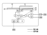
- 1 is a system configuration diagram of a solar power generation device for a vehicle according to the present invention.
- the vehicle solar power generation device of the present invention is a retrofittable vehicular solar power generation device that is installed on the base carrier of the roof of the vehicle and can be used as is without changing the charging system of the vehicle.
- the device includes a clamp for fixing the frame to the base carrier, a slide rail, and a solar power generation panel.
- the solar power generation panel described above has a plurality of power generation panels arranged approximately parallel to each other in the vertical direction, and a fixed panel fixed to a frame is arranged at the top, and below this fixed panel. There is a movable panel on the side that can be expanded and stored.
- a fixed rail is fixed to the frame
- a movable rail supports the movable panel
- the movable panel is expanded and stored by sliding the movable rail.
- the movable panel protrudes from the fixed panel and is exposed when unfolded, so when the vehicle is parked, the panel area can be increased and the power generation capacity using sunlight can be increased. Furthermore, as shown in FIG. 1, since the movable panel fits under the fixed panel when stored, it is possible to prevent air resistance from increasing when driving or in strong winds, and to prevent the movable panel from being damaged due to wind resistance.
- the vehicle solar power generation device of the present invention is attached to the base carrier of the vehicle roof using a clamp, it is easy to attach and detach the device to the vehicle.
- the number of movable panels is not limited to one, and may be arranged in multiple stages depending on the required area of the solar power generation panel.
- the solar power generation device for a vehicle has a housing. By housing the slide rail and the movable panel in the housing, wind can be prevented from entering between the fixed panel and the movable panel when the vehicle is stored, and wind noise during travel can be reduced.
- the casing is waterproof, it is possible to prevent failure of electronic equipment such as a control device, which will be described later, and corrosion and staining of various parts such as slide rails.
- the casing may be a separate member from the frame, or may be a member formed integrally with the frame. Further, the upper surface of the housing may be formed of a fixed panel.
- the movable panel may be deployed forward of the vehicle and exposed to the outside of the casing, or to the side of the vehicle and exposed to the outside of the casing.
- the movable panel When the movable panel is deployed to the front of the vehicle, it acts as an eaves that prevents sunlight from shining into the interior of the vehicle through the windshield, suppressing the rise in temperature inside the vehicle and reducing discomfort when getting into the vehicle. Furthermore, when the movable panel is deployed to the side of the vehicle, it is possible to provide shade to the side of the vehicle.
- the movable panel When deploying the movable panel to the front of the vehicle, the movable panel is located at a higher position than the driver's line of sight and is easily overlooked.
- a restraining member is provided on the slide rail. This avoids the risk of other vehicles colliding with the movable panel while the vehicle is parked.
- the slide rail includes a slide lock mechanism and a spring biased in a direction to accommodate the movable panel.
- the slide lock mechanism prevents the movable panel from being housed in the housing by the spring when the movable panel is unfolded. By simply releasing the slide lock mechanism manually, the biased spring will release the movable panel.
- the movable panel can be easily stored in the housing.
- the movable panel is housed in the housing simply by releasing the slide lock mechanism, so the movable panel can be housed quickly and easily, and dangers in the event of an abnormality can be avoided.
- the vehicular solar power generation device may include a storage battery, a solar charger, a power conversion device, an actuator, a charging cable, a control device for controlling these, and the like in the casing, as necessary.
- FIG. 4 shows a system configuration diagram of a solar power generation device for a vehicle.
- a control device and an actuator provided on the slide rail may be operated by the control device to expand and store the movable panel. This makes it possible to automatically deploy and store movable panels depending on the situation.
- the movable panels can be deployed to further increase the amount of power generated, and when power is not being generated, such as at night or in the rain, the movable panels can be retracted. This prevents the movable panel from inadvertently breaking down.
- the control device detects that the strain on the slide rail exceeds a predetermined value using the strain sensor or pressure sensor installed on the slide rail, the movable panel is retracted so that the movable panel is not blown away by strong winds. It can prevent damage.
- the slide rail is equipped with the above slide lock mechanism and the above spring in addition to the actuator, even if the actuator breaks down, the movable panel can be stored by manually or using a control device to release the slide lock mechanism. It is.
- the vehicle solar power generation device may include a storage battery within the housing. If the vehicle solar power generation device itself has a storage battery, the power generated by the solar power generation panel can be stored, and power can be supplied even when the solar power generation panel is not generating power.
- the control device stops supplying the power generated by the solar power generation panel to the storage battery when the amount of electricity stored in the storage battery exceeds the charging upper limit value. This can prevent the storage battery from becoming overcharged and failing.
- the amount of electricity stored in a storage battery can be known from its voltage value.
- control device When stopping charging the storage battery from the solar power generation panel, it is preferable that the control device operates the actuator to retract the movable panel. This can prevent the movable panel from inadvertently breaking down.
- the solar power generation panel and the storage battery are connected via a solar charger, as shown in Figure 4, and the above control device controls the output voltage and output current of the solar power generation panel using the solar charger, and It performs maximum power point follow-up control of the photovoltaic panel, and controls charging by lowering the voltage to a level that can charge the storage battery.
- the vehicle solar power generation device may include a power conversion device within the housing.
- the power conversion device can convert the voltage of the storage battery into a voltage suitable for an external power supply destination and supply the voltage.
- Examples of the supply voltage include DC 48V, DC 20V, and DC 12V for charging the drive battery and auxiliary battery of an electric vehicle, as well as AC 100V and AC 200V that are supplied to residential home appliances.
- the control device stops supplying to the outside when the amount of electricity stored in the storage battery is less than a lower discharge limit. Thereby, it is possible to prevent the storage battery from over-discharging and accelerating deterioration.
- the vehicle solar power generation device includes a charging cable that can be connected to a charging port of a vehicle.
- a charging cable that runs outside the vehicle, power from the storage battery can be supplied to the vehicle's drive battery and auxiliary battery via the power conversion device. This makes it possible to extend the cruising distance of the vehicle.
- the charging cable may be connected and fixed to the power converter, or may be a removable cable that can be connected to the power converter. Furthermore, if the charging cable has a sufficient length, it is possible to supply not only the vehicle equipped with the vehicle solar power generation device described above but also other vehicles.
- the control device converts the voltage of the storage battery when the amount of electricity stored in the storage battery is equal to or higher than a charging start voltage value, and supplies the voltage to the outside. Then, when the power is supplied to the lower discharge limit, the supply to the outside is stopped, and when the amount of stored power in the storage battery is restored by the solar power generation panel and the voltage reaches the charging start voltage or higher, the power supply is resumed.
- this charging start voltage value is a voltage value lower than the charging upper limit value.
- the solar power generation panel will generate electricity and the amount of electricity stored in the storage battery will increase. It can automatically charge the vehicle's drive battery when the amount increases.
- control device deploys the movable panel to increase the amount of power generated by the photovoltaic panel when the charging cable is connected to the charging port of the vehicle, and retracts the movable panel when the charging cable is disconnected. .
- the vehicle solar power generation device is equipped with a residential outlet. Having a residential outlet makes it possible to use general home appliances.
- the casing includes cooling fins. Heat generated from electronic equipment such as a power conversion device and a control device can be released to the outside of the casing, thereby preventing failure of the electronic equipment.
- the electronic device can be cooled by the wind flowing between it and the roof of the vehicle, and the design quality can be prevented from deteriorating.
- the control device includes a storage unit.
- This storage unit stores the amount of power generated by the solar power generation panel over time, the amount of electricity stored in the storage battery, the amount of power supplied to the outside, the time when the charging cable was connected to the charging port, and the like.
- the movable panels of the solar power generation panels can be deployed to increase the amount of electricity stored in the storage battery before the amount of power supplied to the outside increases. can be increased and prepared for external supply.
- the time when the charging cable is removed from the charging port predicted from the information stored in the storage unit, that is, the time when the user is expected to drive the vehicle. By this time, the supply from the storage battery to the drive battery has ended.
- the amount of electricity stored in the storage battery at the end of supply to the drive battery is the lower limit of discharge. This prevents excess power from being stored in the storage battery while the vehicle is running, making it possible to extend the cruising distance of the vehicle.
- the fixed panels generate solar power even when the vehicle is running, the amount of electricity stored in the storage battery increases, so electricity can be used immediately upon arrival.
- control device includes a communication section.
- the communication unit communicates with an external device such as a smartphone through a mobile phone line, WiFi, BlueTooth, or the like.
- the control device transmits the information stored in the storage unit in response to a request from an external device connected via wireless communication. This allows the user to know information such as the amount of electricity stored in the storage battery using the external device.
- the external device may issue an instruction to the control device to supply power from the storage battery to the drive battery of the vehicle.
- the control device When the charging cable is connected to the charging port of the vehicle, the control device receives instructions from the external device and supplies power from the storage battery to the driving battery of the vehicle.
- the electric power from the storage battery can be transferred to the drive battery by the time the user starts driving the vehicle.
- the amount of stored electricity can be reduced to the lower discharge limit, making it possible to extend the cruising distance of the vehicle.
Abstract
The solar power generator according to the present invention is installed on a base carrier on the roof of a vehicle, and comprises a frame, a clamp that fixes the frame to the base carrier, a slide rail, and a solar power generation panel. The solar power generation panel comprises a fixed panel that is fixed on the frame and positioned at the uppermost part, and a movable panel that is positioned under the fixed panel. The slide rail comprises a fixed rail that is fixed to the frame, and a movable rail that supports the movable panel so that the movable panel can be deployed and retracted. Thus, it is possible to provide a solar power generator for a vehicle that can increase the amount of power generated by a solar power generation panel, while preventing design degradations.
Description
本発明は、車両用太陽光発電装置に係り、更に詳細には、電動自動車に後付けできる車両用太陽光発電装置に関する。
The present invention relates to a solar power generation device for a vehicle, and more particularly to a solar power generation device for a vehicle that can be retrofitted to an electric vehicle.
外部電源から充電できるEV、PHVなどの電気自動車が知られており、これら車両の屋根などに太陽光発電パネルを設け、太陽光により発電した電力を駆動バッテリや補機バッテリに供給することが行われている。
Electric vehicles such as EVs and PHVs that can be charged from an external power source are known, and it is possible to install solar power generation panels on the roofs of these vehicles and supply electricity generated from sunlight to drive batteries and auxiliary batteries. It is being said.
しかしながら、太陽光発電パネルを車両の屋根のみ設ける場合は、太陽光発電パネルによる発電量が制限され、また、車両のボンネットや側面にも太陽光発電パネルを設けると、車両のデザイン性が低下してしまう。
However, if a solar power generation panel is installed only on the roof of a vehicle, the amount of power generated by the solar power generation panel will be limited, and if a solar power generation panel is also installed on the hood or side of the vehicle, the design of the vehicle will deteriorate. It ends up.
本発明は、このような従来技術の有する課題に鑑みてなされたものであり、その目的とするところは、太陽光発電パネルを車両の屋根のみに設けてデザイン性の低下を防止しつつ、太陽光発電パネルによる発電量を増大できる車両用太陽光発電装置を提供することにある。
The present invention has been made in view of the problems faced by the prior art, and its purpose is to provide a solar power generation panel only on the roof of the vehicle, thereby preventing deterioration in design while also providing solar power generation panels only on the roof of the vehicle. An object of the present invention is to provide a solar power generation device for a vehicle that can increase the amount of power generated by a photovoltaic panel.
本発明者は、上記目的を達成すべく鋭意検討を重ねた結果、車両の屋根に固定された太陽光発電パネルに加えて、展開・収納できる可動性の太陽光発電パネルを設けることにより、上記目的が達成できることを見出し、本発明を完成するに至った。
As a result of extensive studies to achieve the above object, the inventor of the present invention achieved the above goal by providing a movable solar power generation panel that can be expanded and stored in addition to the solar power generation panel fixed to the roof of the vehicle. The inventors have discovered that the object can be achieved and have completed the present invention.
即ち、本発明の太陽光発電装置は、車両のルーフのベースキャリアに設置される太陽光発電装置であり、フレームと、上記ベースキャリアに上記フレームを固定するクランプと、スライドレールと、太陽光発電パネルと、を備える。
そして、上記太陽光発電パネルが、上記フレームに固定されて最上部に位置する固定パネルと、上記固定パネルの下側に位置する可動パネルと、を有し、
上記スライドレールは、固定レールが上記フレームに固定され、可動レールで上記可動パネルを支持し、上記可動パネルを展開・収納することを特徴とする。 That is, the solar power generation device of the present invention is a solar power generation device installed on a base carrier on the roof of a vehicle, and includes a frame, a clamp for fixing the frame to the base carrier, a slide rail, and a solar power generation panel. , is provided.
and the solar power generation panel has a fixed panel fixed to the frame and located at the top, and a movable panel located below the fixed panel,
The slide rail is characterized in that a fixed rail is fixed to the frame, a movable rail supports the movable panel, and the movable panel is expanded and stored.
本発明によれば、固定された太陽光発電パネルと、該太陽光発電パネルの下側にスライドレールに支持されて展開・収納可能な可動太陽光パネルを設けることとしたため、デザイン性低下を防止しつつ、太陽光発電パネルによる発電量を増大できる車両用太陽光発電装置を提供することができる。
According to the present invention, a fixed solar power generation panel and a movable solar panel that is supported by a slide rail and can be expanded and stored are provided below the solar power generation panel, thereby preventing deterioration in design quality. At the same time, it is possible to provide a solar power generation device for a vehicle that can increase the amount of power generated by the solar power generation panel.
本発明の車両用太陽光発電装置について詳細に説明する。
本発明の車両用太陽光発電装置は、車両のルーフのベースキャリアに設置されて、車両の充電システムを変更せずにそのまま活用できる、後付けが可能な車両用太陽光発電装置であり、フレームと、上記ベースキャリアに上記フレームを固定するクランプと、スライドレールと、太陽光発電パネルと、を備える。 The vehicle solar power generation device of the present invention will be explained in detail.
The vehicular solar power generation device of the present invention is a retrofittable vehicular solar power generation device that is installed on the base carrier of the roof of the vehicle and can be used as is without changing the charging system of the vehicle. The device includes a clamp for fixing the frame to the base carrier, a slide rail, and a solar power generation panel.
上記太陽光発電パネルは、図1に示すように、複数の発電パネルが上下方向に略平行に配置されており、最上部には、フレームに固定された固定パネルが配置され、この固定パネル下側に展開・収納可能な可動パネルが配置されている。
As shown in Figure 1, the solar power generation panel described above has a plurality of power generation panels arranged approximately parallel to each other in the vertical direction, and a fixed panel fixed to a frame is arranged at the top, and below this fixed panel. There is a movable panel on the side that can be expanded and stored.
上記スライドレールは、固定レールが上記フレームに固定され、可動レールが上記可動パネルを支持しており、可動レールがスライドすることで上記可動パネルを展開・収納する。
In the slide rail, a fixed rail is fixed to the frame, a movable rail supports the movable panel, and the movable panel is expanded and stored by sliding the movable rail.
上記可動パネルは、図2に示すように、展開時には固定パネルから突出して露出するので、駐車時にはパネル面積を増加させて太陽光による発電能力を高めることができる。また、図1に示すように、収納時には固定パネルの下に入り込むので、走行時や強風時に空気抵抗が増大することを防止でき、風の抵抗を受けて可動パネルが破損することを防止できる。
As shown in FIG. 2, the movable panel protrudes from the fixed panel and is exposed when unfolded, so when the vehicle is parked, the panel area can be increased and the power generation capacity using sunlight can be increased. Furthermore, as shown in FIG. 1, since the movable panel fits under the fixed panel when stored, it is possible to prevent air resistance from increasing when driving or in strong winds, and to prevent the movable panel from being damaged due to wind resistance.
また、本発明の車両用太陽光発電装置の車両のルーフのベースキャリアへの取り付けは、クランプによってなされるので、車両への脱着が容易である。
Furthermore, since the vehicle solar power generation device of the present invention is attached to the base carrier of the vehicle roof using a clamp, it is easy to attach and detach the device to the vehicle.
したがって、例えば、高速道路を長時間走行するときなど、太陽光による発電量よりも、空気抵抗の増大による電力消費量の方が大きくなることが予想される場合には容易に取り外すことができる。また、キャンプなど、駐車時間が長くなる時には容易に取り付けて、太陽光により発電した電力を利用することができる。
Therefore, it can be easily removed when the amount of power consumed due to increased air resistance is expected to be greater than the amount of power generated by sunlight, such as when driving on a highway for a long time. It can also be easily installed when parking for a long time, such as when camping, and utilizes electricity generated from sunlight.
上記可動パネルは、図3に示すように、1つに限られず、必要とされる太陽光発電パネルの面積に応じて、複数段重ねて配置することもできる。
As shown in FIG. 3, the number of movable panels is not limited to one, and may be arranged in multiple stages depending on the required area of the solar power generation panel.
上記車両用太陽光発電装置は筐体を有することが好ましい。上記スライドレールや上記可動パネルを筐体内に収容することで、収納時に固定パネルと可動パネルとの間などに風が入り込むことを防止でき、走行時の風切り音を低減することができる。
It is preferable that the solar power generation device for a vehicle has a housing. By housing the slide rail and the movable panel in the housing, wind can be prevented from entering between the fixed panel and the movable panel when the vehicle is stored, and wind noise during travel can be reduced.
また、上記筐体が防水性を有していれば、後述する制御装置などの電子機器の故障やスライドレールなどの各種部品の腐食や汚損などを防止できる。
Furthermore, if the casing is waterproof, it is possible to prevent failure of electronic equipment such as a control device, which will be described later, and corrosion and staining of various parts such as slide rails.
上記筐体は、フレームと別の部材であっても、フレームと一体化して形成された部材であってもよい。また、筐体の上面は固定パネルで形成されていてもよい。
The casing may be a separate member from the frame, or may be a member formed integrally with the frame. Further, the upper surface of the housing may be formed of a fixed panel.
上記可動パネルの展開方向は、車両の前方に展開して上記筐体の外側に露出してもよく、車両の側方に展開して上記筐体の外側に露出してもよい。
The movable panel may be deployed forward of the vehicle and exposed to the outside of the casing, or to the side of the vehicle and exposed to the outside of the casing.
可動パネルが車両の前方に展開するときは、フロントガラスから車内に日が差し込むのを防止する庇となって車内の温度上昇を抑止し、車両に乗り込んだときの不快感を低減できる。また、可動パネルが車両の側方に展開するときは、車両横に日陰を提供することができる。
When the movable panel is deployed to the front of the vehicle, it acts as an eaves that prevents sunlight from shining into the interior of the vehicle through the windshield, suppressing the rise in temperature inside the vehicle and reducing discomfort when getting into the vehicle. Furthermore, when the movable panel is deployed to the side of the vehicle, it is possible to provide shade to the side of the vehicle.
上記可動パネルを、車両の前方に展開させるときは、可動パネルは、運転者の視線よりも高い位置にあり見落とされ易いので、可動パネルの先端が車両の先端よりも前方に突出しないように、上記スライドレールに制止部材を設ける。これにより、駐車中に他車が可動パネルに衝突する危険性を回避できる。
When deploying the movable panel to the front of the vehicle, the movable panel is located at a higher position than the driver's line of sight and is easily overlooked. A restraining member is provided on the slide rail. This avoids the risk of other vehicles colliding with the movable panel while the vehicle is parked.
上記スライドレールは、スライドロック機構と、上記可動パネルを収納する方向に付勢したバネとを備えることが好ましい。
Preferably, the slide rail includes a slide lock mechanism and a spring biased in a direction to accommodate the movable panel.
スライドロック機構は、可動パネルを展開したときに上記バネによって可動パネルが筐体内に収納されることを防止するものであり、このスライドロック機構を手動で解除するだけで、付勢されたバネにより可動パネルを容易に筐体内に収納することができる。
The slide lock mechanism prevents the movable panel from being housed in the housing by the spring when the movable panel is unfolded. By simply releasing the slide lock mechanism manually, the biased spring will release the movable panel. The movable panel can be easily stored in the housing.
また、異常が起こったときにも、スライドロック機構を解除するだけで上記可動パネルが筐体内に収容されるので、可動パネルの収容を迅速かつ容易に行え、異常時の危険をも回避できる。
Furthermore, even when an abnormality occurs, the movable panel is housed in the housing simply by releasing the slide lock mechanism, so the movable panel can be housed quickly and easily, and dangers in the event of an abnormality can be avoided.
上記車両用太陽光発電装置は、必要に応じて、蓄電池、ソーラーチャージャー、電力変換装置、アクチュエータ、充電ケーブル及びこれらの制御を行う制御装置などを、上記筐体内に備えることができる。図4に車両用太陽光発電装置のシステム構成図を示す。
The vehicular solar power generation device may include a storage battery, a solar charger, a power conversion device, an actuator, a charging cable, a control device for controlling these, and the like in the casing, as necessary. FIG. 4 shows a system configuration diagram of a solar power generation device for a vehicle.
制御装置とスライドレールに設けられたアクチュエータとを、上記制御装置がアクチュエータを操作して可動パネルの展開・収納を行ってもよい。これにより状況に応じた可動パネルの展開・収納を自動で行うことが可能である。
A control device and an actuator provided on the slide rail may be operated by the control device to expand and store the movable panel. This makes it possible to automatically deploy and store movable panels depending on the situation.
例えば、太陽光発電パネルの発電量に基づき、発電が行われているときには可動パネルを展開してさらに発電量を増加させ、夜間や雨天時など発電が行われていないときには可動パネルを収納することで、不用意に可動パネルが故障することを防止できる。
For example, based on the amount of power generated by a solar power generation panel, when power is being generated, the movable panels can be deployed to further increase the amount of power generated, and when power is not being generated, such as at night or in the rain, the movable panels can be retracted. This prevents the movable panel from inadvertently breaking down.
また、制御装置が、スライドレールに設けられた歪センサや圧力センサによりスライドレールの歪が所定値以上になったことを検知したとき、可動パネルを収納することによって可動パネルが強風に煽られて破損することなどを防止できる。
In addition, when the control device detects that the strain on the slide rail exceeds a predetermined value using the strain sensor or pressure sensor installed on the slide rail, the movable panel is retracted so that the movable panel is not blown away by strong winds. It can prevent damage.
また、スライドレールがアクチュエータに加えて、上記スライドロック機構と上記バネとを備えていれば、アクチュエータが故障したとしても、手動又は制御装置がスライドロック機構を解除することで可動パネルの収納が可能である。
Furthermore, if the slide rail is equipped with the above slide lock mechanism and the above spring in addition to the actuator, even if the actuator breaks down, the movable panel can be stored by manually or using a control device to release the slide lock mechanism. It is.
上記車両用太陽光発電装置は、上記筐体内に蓄電池を備えることができる。
車両用太陽光発電装置自体が蓄電池を有すれば、太陽光発電パネルでの発電電力を蓄えることができ、太陽光発電パネルが発電していないときでも電力供給が可能になる。 The vehicle solar power generation device may include a storage battery within the housing.
If the vehicle solar power generation device itself has a storage battery, the power generated by the solar power generation panel can be stored, and power can be supplied even when the solar power generation panel is not generating power.
上記制御装置は、上記蓄電池の蓄電量が充電上限値以上になったときは、太陽光発電パネルが発電した電力の上記蓄電池への供給を停止する。これにより、蓄電池が過充電となって故障することを防止できる。蓄電池の蓄電量はその電圧値により知ることができる。
The control device stops supplying the power generated by the solar power generation panel to the storage battery when the amount of electricity stored in the storage battery exceeds the charging upper limit value. This can prevent the storage battery from becoming overcharged and failing. The amount of electricity stored in a storage battery can be known from its voltage value.
太陽光発電パネルから蓄電池への充電を停止するとき、制御装置はアクチュエータを操作して可動パネルを収納することが好ましい。これにより、不用意な可動パネルの故障を防止できる。
When stopping charging the storage battery from the solar power generation panel, it is preferable that the control device operates the actuator to retract the movable panel. This can prevent the movable panel from inadvertently breaking down.
なお、太陽光発電パネルと蓄電池とは、図4に示すように、ソーラーチャージャーを介して接続されており、上記制御装置はソーラーチャージャーによって太陽光発電パネルの出力電圧や出力電流を制御し、太陽光発電パネルの最大電力点追従制御を行うと共に、蓄電池に充電可能な電圧に降圧して充電の制御を行う。
The solar power generation panel and the storage battery are connected via a solar charger, as shown in Figure 4, and the above control device controls the output voltage and output current of the solar power generation panel using the solar charger, and It performs maximum power point follow-up control of the photovoltaic panel, and controls charging by lowering the voltage to a level that can charge the storage battery.
上記車両用太陽光発電装置は、上記筐体内に電力変換装置を備えることができる。
電力変換装置により、蓄電池の電圧を外部の電力供給先に応じた電圧に変換して供給することができる。 The vehicle solar power generation device may include a power conversion device within the housing.
The power conversion device can convert the voltage of the storage battery into a voltage suitable for an external power supply destination and supply the voltage.
供給電圧としては、例えば、電気自動車の駆動用バッテリや補機バッテリを充電するDC48V、DC20V、DC12Vの他、住宅用の家電製品に供給するAC100Vや、AC200Vなどを挙げることができる。
Examples of the supply voltage include DC 48V, DC 20V, and DC 12V for charging the drive battery and auxiliary battery of an electric vehicle, as well as AC 100V and AC 200V that are supplied to residential home appliances.
上記制御装置は、上記蓄電池の蓄電量が放電下限値未満のとき、外部への供給を停止することが好ましい。これにより、蓄電池が過放電となって劣化が促進されることを防止できる。
Preferably, the control device stops supplying to the outside when the amount of electricity stored in the storage battery is less than a lower discharge limit. Thereby, it is possible to prevent the storage battery from over-discharging and accelerating deterioration.
上記車両用太陽光発電装置は、車両の充電ポートに接続できる充電ケーブルを備えることが好ましい。車両の外部を通る充電ケーブルにより、車両用太陽光発電装置と車両の充電ポートとを接続することで、電力変換装置を介して蓄電池の電力を車両の駆動用バッテリや補機バッテリに供給することが可能になり、車両の航続可能距離を延ばすことができる。
Preferably, the vehicle solar power generation device includes a charging cable that can be connected to a charging port of a vehicle. By connecting the vehicle solar power generation device and the vehicle's charging port using a charging cable that runs outside the vehicle, power from the storage battery can be supplied to the vehicle's drive battery and auxiliary battery via the power conversion device. This makes it possible to extend the cruising distance of the vehicle.
充電ケーブルは、電力変換装置に接続固定されていてもよく、電力変換装置に接続できる取り外しが可能なケーブルであってもよい。また、充電ケーブルが十分な長さを有することで、上記車両用太陽光発電装置を車載した車両だけでなく、他車への供給も可能である。
The charging cable may be connected and fixed to the power converter, or may be a removable cable that can be connected to the power converter. Furthermore, if the charging cable has a sufficient length, it is possible to supply not only the vehicle equipped with the vehicle solar power generation device described above but also other vehicles.
上記充電ケーブルが車両の充電ポートに接続されているとき、上記制御装置は、上記蓄電池の蓄電量が充電開始電圧値以上で上記蓄電池の電圧を変換し、外部への供給を行うことが好ましい。
そして、放電下限値まで給電したら外部への供給をストップし、太陽光発電パネルによって蓄電池の蓄電量が回復し、充電開始電圧以上になったら給電再開する。なお、この充電開始電圧値は上記充電上限値よりも低い電圧値である。 When the charging cable is connected to a charging port of a vehicle, it is preferable that the control device converts the voltage of the storage battery when the amount of electricity stored in the storage battery is equal to or higher than a charging start voltage value, and supplies the voltage to the outside.
Then, when the power is supplied to the lower discharge limit, the supply to the outside is stopped, and when the amount of stored power in the storage battery is restored by the solar power generation panel and the voltage reaches the charging start voltage or higher, the power supply is resumed. Note that this charging start voltage value is a voltage value lower than the charging upper limit value.
これにより、蓄電池の蓄電量が少なく、車両の駆動バッテリなどに充電できない場合であっても、充電ケーブルを車両の充電ポートに接続しておけば、太陽光発電パネルが発電して蓄電池の蓄電量が増加したときに自動で車両の駆動バッテリなどに充電することができる。
As a result, even if the amount of electricity stored in the storage battery is low and the vehicle's drive battery cannot be charged, if the charging cable is connected to the vehicle's charging port, the solar power generation panel will generate electricity and the amount of electricity stored in the storage battery will increase. It can automatically charge the vehicle's drive battery when the amount increases.
また、制御装置は、充電ケーブルが車両の充電ポートに接続されたら、可動パネルを展開して太陽光発電パネルによる発電量を増加させ、充電ケーブルが外されたら、可動パネルを格納することが好ましい。
Preferably, the control device deploys the movable panel to increase the amount of power generated by the photovoltaic panel when the charging cable is connected to the charging port of the vehicle, and retracts the movable panel when the charging cable is disconnected. .
車両の充電ポートへの充電ケーブルの接続の有無により可動パネルを展開・収納を行うことにより、短時間の停車時に可動パネルを展開することなく、可動パネルを展開・収納を自動で行うことが可能である。
By deploying and retracting the movable panel depending on whether or not the charging cable is connected to the vehicle's charging port, it is possible to automatically deploy and retract the movable panel without having to deploy it when the vehicle is stopped for a short time. It is.
上記車両用太陽光発電装置は、住宅用コンセントを備えることが好ましい。住宅用コンセントを有することで、一般家電製品を使用することが可能になる。
Preferably, the vehicle solar power generation device is equipped with a residential outlet. Having a residential outlet makes it possible to use general home appliances.
上記筐体は冷却フィンを備えることが好ましい。電力変換装置や制御装置などの電子機器から生じる熱を筐体の外に逃がし、上記電子機器の故障を防止することができる。
Preferably, the casing includes cooling fins. Heat generated from electronic equipment such as a power conversion device and a control device can be released to the outside of the casing, thereby preventing failure of the electronic equipment.
また、冷却フィンが、筐体の下面に設けられていれば、車両の屋根との間を流れる風によって上記電子機器の冷却が可能であると共に、デザイン性の低下を防止できる。
Furthermore, if cooling fins are provided on the lower surface of the casing, the electronic device can be cooled by the wind flowing between it and the roof of the vehicle, and the design quality can be prevented from deteriorating.
上記制御装置は記憶部を備えていることが好ましい。この記憶部には、時間経過に伴う太陽光発電パネルの発電量、上記蓄電池の蓄電量、外部への供給量及び充電ケーブルを充電ポートに接続した時刻などを記憶しておく。
Preferably, the control device includes a storage unit. This storage unit stores the amount of power generated by the solar power generation panel over time, the amount of electricity stored in the storage battery, the amount of power supplied to the outside, the time when the charging cable was connected to the charging port, and the like.
これにより、車両用太陽光発電装置の使用者の電力利用パターンを予測することができ、外部に供給する電力量が増加する前に、太陽光発電パネルの可動パネルを展開して蓄電池の蓄電量を増やし、外部への供給に備えることができる。
As a result, it is possible to predict the power usage pattern of users of vehicle solar power generation devices, and the movable panels of the solar power generation panels can be deployed to increase the amount of electricity stored in the storage battery before the amount of power supplied to the outside increases. can be increased and prepared for external supply.
また、充電ケーブルが車両の充電ポートに接続されているときは、記憶部が記憶した情報から予測した、充電ケーブルを充電ポートから外す時刻、すなわち、使用者が車両を走行させると予測される時間までに、蓄電池から駆動バッテリへの供給を終了させる。
In addition, when the charging cable is connected to the charging port of the vehicle, the time when the charging cable is removed from the charging port predicted from the information stored in the storage unit, that is, the time when the user is expected to drive the vehicle. By this time, the supply from the storage battery to the drive battery has ended.
駆動バッテリへの供給終了時の蓄電池の蓄電量は、放電下限値である。これにより、車両走行時に蓄電池に余剰の電力を蓄えられていることが防止され、車両の航続可能距離を延ばすことが可能になる。
The amount of electricity stored in the storage battery at the end of supply to the drive battery is the lower limit of discharge. This prevents excess power from being stored in the storage battery while the vehicle is running, making it possible to extend the cruising distance of the vehicle.
なお、車両の走行時にも固定パネルによる太陽光発電が行われて蓄電池の蓄電量が増加するので、到着したら直ちに電力の利用が可能である。
Furthermore, as the fixed panels generate solar power even when the vehicle is running, the amount of electricity stored in the storage battery increases, so electricity can be used immediately upon arrival.
上記制御装置は通信部を備えていることが好ましい。通信部は、携帯電話回線、WiFi、BlueToothなどを通じて、スマートフォンなどの外部機器との通信を行う。
Preferably, the control device includes a communication section. The communication unit communicates with an external device such as a smartphone through a mobile phone line, WiFi, BlueTooth, or the like.
制御装置は、無線通信により接続された外部機器からの要求に応じて、上記記憶部に記憶した情報を送信する。これにより、使用者は、蓄電池の蓄電量などの情報を外部機器により知ることが可能になる。
The control device transmits the information stored in the storage unit in response to a request from an external device connected via wireless communication. This allows the user to know information such as the amount of electricity stored in the storage battery using the external device.
また、上記外部機器から制御装置に対して、蓄電池から車両の駆動バッテリへの供給を行う指示をだすことも可能である。
It is also possible for the external device to issue an instruction to the control device to supply power from the storage battery to the drive battery of the vehicle.
充電ケーブルが車両の充電ポートに接続されているとき、制御装置は外部機器からの指示を受けて、蓄電池から車両の駆動バッテリへの供給を行う。
When the charging cable is connected to the charging port of the vehicle, the control device receives instructions from the external device and supplies power from the storage battery to the driving battery of the vehicle.
これにより、記憶部が記憶した、充電ケーブルを充電ポートに接続するパターンと異なった使用をする際にも、使用者が車両を走行させる時間までに、蓄電池の電力を駆動バッテリに移し、蓄電池の蓄電量を放電下限値まで減らしておくことができ、車両の航続可能距離を延ばすことが可能になる。
As a result, even if the charging cable is connected to the charging port in a different pattern than the one stored in the memory, the electric power from the storage battery can be transferred to the drive battery by the time the user starts driving the vehicle. The amount of stored electricity can be reduced to the lower discharge limit, making it possible to extend the cruising distance of the vehicle.
1 太陽光発電パネル
11 固定パネル
12 可動パネル
2 スライドレール
21 固定レール
22 可動レール
23 バネ
24 スライドロック機構
25 アクチュエータ
26 歪センサ(圧力センサ)
3 フレーム(筐体)
4 クランプ
5 ソーラーチャージャー
6 蓄電池
7 電力変換装置
71 充電ケーブル
72 住宅用コンセント
8 制御装置
81 記憶部
82 通信部
100 ベースキャリア
200 車両バッテリ
210 充電ポート
300 家電製品
400 外部機器 1 Solarpower generation panel 11 Fixed panel 12 Movable panel 2 Slide rail 21 Fixed rail 22 Movable rail 23 Spring 24 Slide lock mechanism 25 Actuator 26 Strain sensor (pressure sensor)
3 Frame (casing)
4Clamp 5 Solar charger 6 Storage battery 7 Power conversion device 71 Charging cable 72 Residential outlet 8 Control device 81 Storage section 82 Communication section 100 Base carrier 200 Vehicle battery 210 Charging port 300 Home appliance 400 External device
11 固定パネル
12 可動パネル
2 スライドレール
21 固定レール
22 可動レール
23 バネ
24 スライドロック機構
25 アクチュエータ
26 歪センサ(圧力センサ)
3 フレーム(筐体)
4 クランプ
5 ソーラーチャージャー
6 蓄電池
7 電力変換装置
71 充電ケーブル
72 住宅用コンセント
8 制御装置
81 記憶部
82 通信部
100 ベースキャリア
200 車両バッテリ
210 充電ポート
300 家電製品
400 外部機器 1 Solar
3 Frame (casing)
4
Claims (20)
- 車両のルーフのベースキャリアに設置される太陽光発電装置であって、
フレームと、上記ベースキャリアに上記フレームを固定するクランプと、スライドレールと、太陽光発電パネルと、を備え、
上記太陽光発電パネルが、上記フレームに固定されて最上部に位置する固定パネルと、
上記固定パネルの下側に位置する可動パネルと、を有し、
上記スライドレールは、固定レールが上記フレームに固定され、可動レールで上記可動パネルを支持し、上記可動パネルを展開・収納することを特徴とする車両用太陽光発電装置。 A solar power generation device installed on a base carrier on the roof of a vehicle,
A frame, a clamp for fixing the frame to the base carrier, a slide rail, and a solar power generation panel,
a fixed panel in which the solar power generation panel is fixed to the frame and located at the top;
a movable panel located below the fixed panel;
The solar power generation device for a vehicle is characterized in that the slide rail has a fixed rail fixed to the frame, a movable rail that supports the movable panel, and expands and stores the movable panel. - 少なくとも上記スライドレールと上記可動パネルとが筐体に収納され、
上記可動パネルが、車両の前方に展開して上記筐体の外側に露出し、
上記スライドレールに設けられた制止部材により、上記可動パネルの先端が車両の先端よりも前方に突出しないことを特徴とする請求項1に記載の車両用太陽光発電装置。 At least the slide rail and the movable panel are housed in a housing,
The movable panel is deployed to the front of the vehicle and exposed to the outside of the casing,
2. The solar power generation device for a vehicle according to claim 1, wherein a stopping member provided on the slide rail prevents the tip of the movable panel from protruding further forward than the tip of the vehicle. - 少なくとも上記スライドレールと上記可動パネルとが筐体に収納され、
上記可動パネルが、車両の側方に展開して上記筐体の外側に露出することを特徴とする請求項1に記載の車両用太陽光発電装置。 At least the slide rail and the movable panel are housed in a housing,
The solar power generation device for a vehicle according to claim 1, wherein the movable panel is expanded to the side of the vehicle and exposed to the outside of the casing. - 少なくとも上記スライドレールと上記可動パネルとが筐体に収納され、
上記スライドレールが、スライドロック機構と、上記可動パネルを収納する方向に付勢したバネとを備え、スライドロック機構を解除することで上記可動パネルを上記筐体内に収納することを特徴とする請求項1に記載の車両用太陽光発電装置。 At least the slide rail and the movable panel are housed in a housing,
A claim characterized in that the slide rail includes a slide lock mechanism and a spring biased in a direction to house the movable panel, and the movable panel is housed in the housing by releasing the slide lock mechanism. Item 1. The vehicle solar power generation device according to item 1. - 少なくとも上記スライドレールと上記可動パネルとが筐体に収納され、
上記筐体内に、制御装置と、アクチュエータとを、備え、
上記アクチュエータがスライドレールに設けられ、
上記制御装置が上記アクチュエータを操作して可動パネルを展開・収納することを特徴とする請求項1に記載の車両用太陽光発電装置。 At least the slide rail and the movable panel are housed in a housing,
A control device and an actuator are provided in the housing,
The actuator is provided on the slide rail,
The solar power generation device for a vehicle according to claim 1, wherein the control device operates the actuator to expand and store the movable panel. - 上記制御装置は、上記太陽光発電パネルの発電量に基づいて、上記アクチュエータを操作し、可動パネルを展開・収納することを特徴とする請求項5に記載の車両用太陽光発電装置。 The solar power generation device for a vehicle according to claim 5, wherein the control device operates the actuator to expand and stow the movable panel based on the amount of power generated by the solar power generation panel.
- 上記制御装置は、スライドレールの歪が所定値以上のとき、上記アクチュエータを操作し、上記可動パネルを収納することを特徴とする請求項5に記載の車両用太陽光発電装置。 6. The vehicle solar power generation device according to claim 5, wherein the control device operates the actuator and stores the movable panel when the strain of the slide rail is equal to or greater than a predetermined value.
- 上記筐体内に蓄電池を備え、
上記蓄電池に上記太陽光発電パネルの発電電力を蓄えることを特徴とする請求項5に記載の車両用太陽光発電装置。 A storage battery is provided within the housing,
6. The solar power generation device for a vehicle according to claim 5, wherein the power generated by the solar power generation panel is stored in the storage battery. - 上記制御装置は、上記蓄電池の蓄電量が充電上限値以上のときに、上記太陽光発電パネルから上記蓄電池への充電を停止することを特徴とする請求項8に記載の車両用太陽光発電装置。 The solar power generation device for a vehicle according to claim 8, wherein the control device stops charging the storage battery from the solar power generation panel when the amount of electricity stored in the storage battery is equal to or higher than a charging upper limit value. .
- 上記制御装置は、上記太陽光発電パネルから上記蓄電池への充電を停止するとき、上記アクチュエータを操作し、上記可動パネルを収納することを特徴とする請求項9に記載の車両用太陽光発電装置。 The solar power generation device for a vehicle according to claim 9, wherein the control device operates the actuator and stores the movable panel when stopping charging the storage battery from the solar power generation panel. .
- 上記筐体内に電力変換装置を備え、
上記蓄電池の電圧を変換して外部に供給することを特徴とする請求項9に記載の車両用太陽光発電装置。 Equipped with a power conversion device inside the above-mentioned housing,
The solar power generation device for a vehicle according to claim 9, wherein the voltage of the storage battery is converted and supplied to the outside. - 上記制御装置は、上記蓄電池の蓄電量が放電下限値未満のとき、外部への供給を停止することを特徴とする請求項11に記載の車両用太陽光発電装置。 The solar power generation device for a vehicle according to claim 11, wherein the control device stops supplying the power to the outside when the amount of electricity stored in the storage battery is less than a lower discharge limit.
- さらに車両の充電ポートに接続する充電ケーブルを備えることを特徴とする請求項12に記載の車両用太陽光発電装置。 The solar power generation device for a vehicle according to claim 12, further comprising a charging cable connected to a charging port of the vehicle.
- 上記充電ケーブルが車両の充電ポートに接続されているとき、
上記制御装置は、上記蓄電池の蓄電量が充電開始電圧値以上で上記蓄電池の電圧を変換し、外部への供給を行うことを特徴とする請求項12に記載の車両用太陽光発電装置。 When the above charging cable is connected to the vehicle's charging port,
13. The vehicle solar power generation device according to claim 12, wherein the control device converts the voltage of the storage battery when the amount of electricity stored in the storage battery is equal to or higher than a charging start voltage value, and supplies the voltage to the outside. - さらに住宅用コンセントを備えることを特徴とする請求項12に記載の車両用太陽光発電装置。 The solar power generation device for a vehicle according to claim 12, further comprising a residential outlet.
- 上記筐体が、冷却フィンを備えることを特徴とする請求項12に記載の車両用太陽光発電装置。 13. The vehicle solar power generation device according to claim 12, wherein the casing includes cooling fins.
- 上記制御装置が、記憶部を備え、
上記記憶部は、時間経過に伴う、上記太陽光発電パネルの発電量、上記蓄電池の蓄電量、外部への供給量及び充電ケーブルを充電ポートに接続した時刻を記憶することを特徴とする請求項12に記載の車両用太陽光発電装置。 The control device includes a storage unit,
The storage unit stores, over time, the amount of power generated by the solar power generation panel, the amount of electricity stored in the storage battery, the amount of power supplied to the outside, and the time when the charging cable was connected to the charging port. 13. The vehicle solar power generation device according to 12. - 上記制御装置は、
上記充電ケーブルが車両の充電ポートに接続されているとき、
上記記憶部が記憶した情報から予測した、充電ケーブルを充電ポートに接続するパターンに基づいて、
車両の駆動バッテリの電力量の減少開始予測時刻までに上記蓄電池から車両の駆動バッテリへの供給を終了させることを特徴とする請求項17に記載の車両用太陽光発電装置。 The above control device is
When the above charging cable is connected to the vehicle's charging port,
Based on the pattern of connecting the charging cable to the charging port predicted from the information stored in the storage unit,
18. The solar power generation device for a vehicle according to claim 17, wherein the supply from the storage battery to the drive battery of the vehicle is terminated by a predicted time when the amount of electric power of the drive battery of the vehicle starts decreasing. - 上記制御装置が、通信部を備え、
上記記憶部に記憶した情報を、外部に送信することを特徴とする請求項17に記載の車両用太陽光発電装置。 The control device includes a communication section,
18. The vehicle solar power generation device according to claim 17, wherein the information stored in the storage section is transmitted to the outside. - 上記制御装置は、
上記充電ケーブルが車両の充電ポートに接続されているとき、
外部機器からの指示を受けて、上記蓄電池から車両の駆動バッテリへの供給を行うことを特徴とする請求項19に記載の車両用太陽光発電装置。 The above control device is
When the above charging cable is connected to the vehicle's charging port,
20. The solar power generation device for a vehicle according to claim 19, wherein the storage battery supplies power to a drive battery of the vehicle in response to an instruction from an external device.
Priority Applications (1)
| Application Number | Priority Date | Filing Date | Title |
|---|---|---|---|
| PCT/JP2022/027183 WO2024013778A1 (en) | 2022-07-11 | 2022-07-11 | Solar power generator for vehicle |
Applications Claiming Priority (1)
| Application Number | Priority Date | Filing Date | Title |
|---|---|---|---|
| PCT/JP2022/027183 WO2024013778A1 (en) | 2022-07-11 | 2022-07-11 | Solar power generator for vehicle |
Publications (1)
| Publication Number | Publication Date |
|---|---|
| WO2024013778A1 true WO2024013778A1 (en) | 2024-01-18 |
Family
ID=89536243
Family Applications (1)
| Application Number | Title | Priority Date | Filing Date |
|---|---|---|---|
| PCT/JP2022/027183 WO2024013778A1 (en) | 2022-07-11 | 2022-07-11 | Solar power generator for vehicle |
Country Status (1)
| Country | Link |
|---|---|
| WO (1) | WO2024013778A1 (en) |
Citations (5)
| Publication number | Priority date | Publication date | Assignee | Title |
|---|---|---|---|---|
| JPS5792527U (en) * | 1980-11-28 | 1982-06-07 | ||
| JPH1128991A (en) * | 1997-07-14 | 1999-02-02 | Nissei Kinzoku Kk | Solar battery unit for automobile |
| CN102050016A (en) * | 2010-12-14 | 2011-05-11 | 孟强 | Solar charging device of electric automobile |
| JP2013090548A (en) * | 2011-10-21 | 2013-05-13 | Honda Motor Co Ltd | Vehicular power storage system |
| JP2013255405A (en) * | 2012-06-05 | 2013-12-19 | Pai Cho | Auxiliary charging device for electric vehicle |
-
2022
- 2022-07-11 WO PCT/JP2022/027183 patent/WO2024013778A1/en unknown
Patent Citations (5)
| Publication number | Priority date | Publication date | Assignee | Title |
|---|---|---|---|---|
| JPS5792527U (en) * | 1980-11-28 | 1982-06-07 | ||
| JPH1128991A (en) * | 1997-07-14 | 1999-02-02 | Nissei Kinzoku Kk | Solar battery unit for automobile |
| CN102050016A (en) * | 2010-12-14 | 2011-05-11 | 孟强 | Solar charging device of electric automobile |
| JP2013090548A (en) * | 2011-10-21 | 2013-05-13 | Honda Motor Co Ltd | Vehicular power storage system |
| JP2013255405A (en) * | 2012-06-05 | 2013-12-19 | Pai Cho | Auxiliary charging device for electric vehicle |
Similar Documents
| Publication | Publication Date | Title |
|---|---|---|
| JP6145751B2 (en) | In-vehicle power supply | |
| US7884569B2 (en) | Hybrid vehicle with a low voltage solar panel charging a high voltage battery using a series charger to separately charge individual cells of the series connected battery | |
| US8122981B2 (en) | Solar cell system for vehicles and control method thereof | |
| EP2937242B1 (en) | Charging control device using in-vehicle solar cell | |
| US20140225559A1 (en) | Motor-driven travelling body and high-speed charge method for motor-driven travelling body | |
| JP2013066365A (en) | Vehicle driving device, vehicle charging system, and automobile | |
| CN104737359A (en) | Self-contained renewable battery charger | |
| JP6056486B2 (en) | Vehicle power supply device | |
| WO2008127016A1 (en) | Solar cell system for vehicles and control method thereof | |
| EP2258579B1 (en) | Additional autonomous power supply system for vehicle, especially for industrial or commercial vehicle | |
| WO2014030478A1 (en) | Power supply device, solar system, electric system, and vehicle | |
| CN105882569A (en) | Train alternating current-direct current assisting power source system based on light storage complementarity | |
| WO2024013778A1 (en) | Solar power generator for vehicle | |
| KR20190014911A (en) | Movable device for charging the second battery of electric vehicle | |
| JP2007022211A (en) | Power supply device for vehicle | |
| JP2014042404A (en) | Charging device, solar system, electrical system, and vehicle | |
| JP7306240B2 (en) | solar charging system | |
| JP5598216B2 (en) | Vehicle power supply control device | |
| KR20190129436A (en) | Shelter Integrated Electric Vehicle Charging System | |
| JP7006572B2 (en) | Vehicle charge control system | |
| KR101186949B1 (en) | Car current supply system using sun light | |
| CN209972098U (en) | Cooling system in car | |
| US20230278831A1 (en) | Ultracapacitor powered construction elevator | |
| US20230158893A1 (en) | Electric vehicle charging system capable of generating electricity by solar energy | |
| US20240097482A1 (en) | Solar charging system |
Legal Events
| Date | Code | Title | Description |
|---|---|---|---|
| 121 | Ep: the epo has been informed by wipo that ep was designated in this application |
Ref document number: 22950999 Country of ref document: EP Kind code of ref document: A1 |