WO2024009666A1 - 殺菌システム、殺菌装置および制御方法 - Google Patents
殺菌システム、殺菌装置および制御方法 Download PDFInfo
- Publication number
- WO2024009666A1 WO2024009666A1 PCT/JP2023/020755 JP2023020755W WO2024009666A1 WO 2024009666 A1 WO2024009666 A1 WO 2024009666A1 JP 2023020755 W JP2023020755 W JP 2023020755W WO 2024009666 A1 WO2024009666 A1 WO 2024009666A1
- Authority
- WO
- WIPO (PCT)
- Prior art keywords
- light source
- ultraviolet rays
- angle adjustment
- section
- irradiation
- Prior art date
- Legal status (The legal status is an assumption and is not a legal conclusion. Google has not performed a legal analysis and makes no representation as to the accuracy of the status listed.)
- Ceased
Links
Images






Classifications
-
- A—HUMAN NECESSITIES
- A61—MEDICAL OR VETERINARY SCIENCE; HYGIENE
- A61L—METHODS OR APPARATUS FOR STERILISING MATERIALS OR OBJECTS IN GENERAL; DISINFECTION, STERILISATION OR DEODORISATION OF AIR; CHEMICAL ASPECTS OF BANDAGES, DRESSINGS, ABSORBENT PADS OR SURGICAL ARTICLES; MATERIALS FOR BANDAGES, DRESSINGS, ABSORBENT PADS OR SURGICAL ARTICLES
- A61L2/00—Disinfection or sterilisation of materials or objects, in general; Accessories therefor
- A61L2/02—Disinfection or sterilisation of materials or objects, in general; Accessories therefor using physical processes
- A61L2/08—Radiation
- A61L2/10—Ultraviolet [UV] radiation
-
- A—HUMAN NECESSITIES
- A61—MEDICAL OR VETERINARY SCIENCE; HYGIENE
- A61L—METHODS OR APPARATUS FOR STERILISING MATERIALS OR OBJECTS IN GENERAL; DISINFECTION, STERILISATION OR DEODORISATION OF AIR; CHEMICAL ASPECTS OF BANDAGES, DRESSINGS, ABSORBENT PADS OR SURGICAL ARTICLES; MATERIALS FOR BANDAGES, DRESSINGS, ABSORBENT PADS OR SURGICAL ARTICLES
- A61L2/00—Disinfection or sterilisation of materials or objects, in general; Accessories therefor
- A61L2/24—Apparatus using programmed or automatic operation
-
- A—HUMAN NECESSITIES
- A61—MEDICAL OR VETERINARY SCIENCE; HYGIENE
- A61L—METHODS OR APPARATUS FOR STERILISING MATERIALS OR OBJECTS IN GENERAL; DISINFECTION, STERILISATION OR DEODORISATION OF AIR; CHEMICAL ASPECTS OF BANDAGES, DRESSINGS, ABSORBENT PADS OR SURGICAL ARTICLES; MATERIALS FOR BANDAGES, DRESSINGS, ABSORBENT PADS OR SURGICAL ARTICLES
- A61L9/00—Disinfection, sterilisation or deodorisation of air
- A61L9/16—Disinfection, sterilisation or deodorisation of air using physical phenomena
- A61L9/18—Radiation
- A61L9/20—Ultraviolet radiation
Definitions
- ultraviolet rays within a certain wavelength range have little effect on humans (skin, eyes, etc.) and can kill bacteria without harming human cells.
- Patent Document 1 Using ultraviolet rays in a wavelength range that has little effect on people, sterilization can be performed even in environments where there are people, so its use is no longer limited to after-work hours, such as at night, and is advantageous in terms of operational and sterilization effects. .
- the irradiation range of ultraviolet rays may overlap (for example, see Patent Documents 3 and 4).
- each sterilizer is controlled to maintain the above-mentioned permissible limits, double, triple, etc. Due to exposure to ultraviolet radiation, the total exposure may exceed permissible limits. Therefore, it is necessary for a person with knowledge to adjust the arrangement of the sterilizers so that the irradiation ranges of ultraviolet rays do not overlap as much as possible.
- 222nm ultraviolet rays have almost no sterilizing effect on the back side of hair, which is not exposed to the ultraviolet rays, so from the perspective of increasing the sterilizing effect, it is recommended to irradiate ultraviolet rays from different directions from multiple sterilizers. is desired.
- a sterilizer is equipped with a control mechanism that protects the permissible limit value, if multiple sterilizers are irradiating ultraviolet rays, the total amount of light to humans may exceed the permissible cumulative amount of light. This poses a problem from a safety perspective.
- the present invention has been made in view of the above, and aims to provide a sterilization system, a sterilization device, and a control method that can enhance the sterilization effect while ensuring safety for humans.
- a sterilization system includes a sterilization device having a light source section, a horizontal angle adjustment section and/or a vertical angle adjustment section, and a control device.
- the light source unit irradiates ultraviolet rays with wavelengths that have little effect on the human body.
- the horizontal angle adjustment section adjusts the horizontal angle of the light source section by rotating the light source section in a horizontal direction.
- the vertical angle adjustment section adjusts the vertical angle of the light source section by rotating the light source section in a vertical direction.
- the control device controls rotation of the horizontal angle adjustment section and/or the vertical angle adjustment section, and irradiates the object with ultraviolet rays from the light source section.
- Each of the control devices controls rotation of the horizontal angle adjustment section and/or the vertical angle adjustment section based on setting data including irradiation directions for simultaneously irradiating the same object with ultraviolet rays, and irradiates the same object with ultraviolet rays.
- the irradiation of ultraviolet rays is controlled based on the limit value of the exposure amount of ultraviolet rays, which is adjusted by the value based on the number of the plurality of sterilizers that simultaneously irradiate the sterilizers.
- the sterilization system according to one aspect of the present invention can enhance the sterilization effect while ensuring safety for humans.
- FIG. 1 is a block diagram showing an example of the configuration of a sterilizer and the like according to an embodiment.
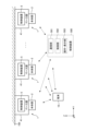
- FIG. 2 is a diagram showing a configuration example in which a plurality of sterilizers and the like are included.
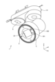
- FIG. 3 is a perspective view showing an example of a mechanical configuration of an example of a sterilizer.
- FIG. 4 is a perspective view showing an example of the mechanical configuration of another example of the sterilizer.
- FIG. 5 is a diagram showing another example of the external appearance of the sterilizer.
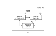
- FIG. 6 is a diagram showing an example of the hardware configuration of a control unit of a control device, a control unit of a terminal, or a control unit of another control device.
- FIG. 1 is a block diagram showing an example of the configuration of a sterilizer and the like according to an embodiment.
- FIG. 2 is a diagram showing a configuration example in which a plurality of sterilizers and the like are included.
- FIG. 3 is a perspective view showing an example of a mechanical configuration of an example
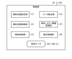
- FIG. 7 is a diagram illustrating a functional configuration example of a control unit of a control device, a control unit of a terminal, or a control unit of another control device.
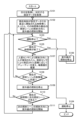
- FIG. 8 is a flowchart showing an example of control by a marker and a control unit of a control device, a control unit of a terminal, or a control unit of another control device.
- FIG. 9A is an example of setting data for an irradiation scene.
- FIG. 9B is an example of setting data for an irradiation scene.
- FIG. 10A is a diagram illustrating an example of a space in which a plurality of sterilizers are installed.
- FIG. 10B is a diagram illustrating an example of setting the first irradiation scene.
- FIG. 10C is a diagram illustrating an example of setting the second irradiation scene.
- FIG. 11 is a diagram showing an example of setting data.
- FIG. 12 is a flowchart showing an example of control by the control unit of the control device, the control unit of the terminal, or the control unit of the control device.
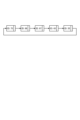
- FIG. 13 is a diagram illustrating an example of sensing timing by the ranging sensor.
- FIG. 1 is a block diagram showing a configuration example of a sterilizer 1 and the like according to an embodiment.
- the sterilizer 1 includes a base portion 41 attached to a ceiling wall 100 constituting a ceiling, for example, a main body portion 2 having a light source portion 21, and a vertical angle adjustment that rotatably supports the main body portion 2. 3, a horizontal angle adjustment section 4, and a control device 5.
- the X direction in FIG. 1 is the horizontal direction, which is the front-back direction of the sterilizer 1 in the illustrated state.
- the Y direction is a horizontal direction, and is the width direction of the sterilizer 1 in the illustrated state.
- the Z direction is a vertical direction perpendicular to the horizontal direction, and is a vertical direction of the sterilizer 1.
- the Z direction is parallel to the vertical direction of the space S to be sterilized, but the Z direction is not limited to this, and the Z direction may be inclined to the vertical direction, or the Z direction may be parallel to the vertical direction. It may be parallel to orthogonal directions.
- the control device 5 controls the sterilization device 1.
- the control device 5 controls the light source section 21, the vertical angle adjustment section 3, and the horizontal angle adjustment section 4, and is housed in the internal space of the base section 41.
- the control device 5 includes a communication section 51 , a control section 52 , a light source section drive circuit 53 , a first motor drive circuit 54 , and a second motor drive circuit 55 .
- the control device 5 controls the light source section 21 to turn on and off the ultraviolet rays, adjusts the irradiation intensity, the vertical angle adjustment section 3 to adjust the vertical angle of the light source section 21, and the horizontal angle adjustment section 4. Adjustment of the horizontal angle of the light source section 21 is performed.
- the hardware configuration of the control device 5 is similar to that of a general control device.
- the power source 200 is a commercial power source, a generator, a battery, or the like.
- the communication unit 51 transmits and receives information to and from the terminal 10 owned by the user, and, for example, receives operation information from the terminal 10, the status of the sterilizer 1, the irradiation status of the light source unit 21 (for example, , lighting/extinguishing, irradiation intensity), and the attitude state (for example, vertical angle and horizontal angle) of the light source unit 21 are transmitted to the terminal 10 .
- the communication unit 51 performs short-range wireless communication such as Wi-Fi (registered trademark) or Bluetooth (registered trademark).
- the control unit 52 performs irradiation control on the light source unit 21, drive control on the first motor 32, drive control on the second motor 42, and the like.
- the irradiation control includes lighting/extinguishing control of the light source section 21, irradiation intensity control, and the like.
- the light source unit drive circuit 53 supplies power to the light source unit 21 based on an irradiation control signal for the light source unit 21 from the control unit 52. If the light source section 21 is of a type that can change the irradiation intensity of ultraviolet rays, the light source section drive circuit 53 also adjusts the irradiation intensity. The light source drive circuit 53 adjusts the on/off duty of ultraviolet irradiation to adjust the amount of irradiation. The light source section drive circuit 53 is electrically connected to the control section 52 and the light source section 21 . Note that although the light source unit drive circuit 53 is included in the control device 5, it is not limited thereto, and the light source unit 21 may also include the light source unit drive circuit 53. Further, when the light source unit 21 is a light source that is a combination of light sources in different wavelength regions, adjustment is performed so that the irradiation intensity of each light source can be adjusted.
- the first motor drive circuit 54 rotates the light source unit 21 in the vertical direction by supplying drive power to the first motor 32 based on a drive control signal for the first motor 32 from the control unit 52. It is.
- the first motor drive circuit 54 is electrically connected to the control section 52 and the first motor 32. Note that, although the first motor drive circuit 54 is included in the control device 5, it is not limited thereto, and the first motor 32 may also include the first motor drive circuit 54.
- the second motor drive circuit 55 rotates the light source unit 21 in the horizontal direction by supplying drive power to the second motor 42 based on a drive control signal for the second motor 42 from the control unit 52. It is.
- the second motor drive circuit 55 is electrically connected to the control section 52 and the second motor 42 . Note that although the second motor drive circuit 55 is included in the control device 5, it is not limited thereto, and the second motor 42 may also include the second motor drive circuit 55.
- the terminal 10 is operated by the user to operate the sterilizer 1, and is also used by the user to grasp the status of the sterilizer 1.
- the terminal 10 includes a communication section 11, a control section 12, and an operation/display section 13.
- the terminal 10 may be a dedicated terminal for the sterilizer 1, or may be a general-purpose terminal such as a smartphone, a tablet, or a laptop computer. Further, the hardware configuration of the terminal 10 is similar to that of a general terminal.
- the communication unit 11 transmits and receives information to and from the control device 5.
- the communication unit 11 performs short-range wireless communication such as Wi-Fi (registered trademark) or Bluetooth (registered trademark). Note that the transmission and reception of information is not limited to wireless communication, but may also be conducted by wire.
- the control unit 12 controls the terminal 10 and outputs operation information to the communication unit 11 based on at least the user's operation on the operation/display unit 13.
- the control unit 12 also controls the display by the operation/display unit 13.
- the control section 12 is electrically connected to the communication section 11 and the operation/display section 13 . Note that the control unit 12 can perform part of the processing for the control unit 52 connected via the communication unit 11 on its own device side and the communication unit 51 on the sterilization device 1 side.
- the operation/display unit 13 is used not only for general operations and displays on the terminal 10 but also for remotely operating the sterilizer 1.
- the operation/display section 13 includes, for example, a switch corresponding to turning on and off the ultraviolet rays, a switch corresponding to the irradiation intensity, a switch corresponding to adjusting the vertical angle of the light source section 21, and a switch corresponding to adjusting the horizontal angle of the light source section 21. Includes switches for adjustment.
- the switch may be a mechanical switch such as energization/de-energization or resistance change, or an electrical switch such as a touch panel.
- a marker sensor 6 such as a CMOS (Complementary Metal Oxide Semiconductor) sensor is provided near the main body portion 2.
- the marker sensor 6 detects a marker signal such as infrared rays (infrared light) emitted from the marker 9 on a two-dimensional image.
- the control unit 52 recognizes the position of the marker 9 from the detection signal (image signal) of the marker sensor 6, directs the UV irradiation direction to the marker 9, and sets the position and range of UV irradiation for sterilization. .
- the marker 9 includes a signal transmission section 91, an ultraviolet sensor 92, a control section 93, and an operation/display section 94.
- the ultraviolet sensor 92 may be omitted in some cases.
- the signal transmitter 91 has a function of transmitting a marker signal using, for example, infrared rays. Note that by changing the pulse pattern of the marker signal, when there are a plurality of markers 9, it is possible to identify the marker signal transmitted from each marker 9.
- the ultraviolet sensor 92 has a function of detecting ultraviolet rays emitted from the light source section 21 of the sterilizer 1. In other words, it can be determined by the ultraviolet sensor 92 that the marker 9 is within the range of ultraviolet rays irradiated by the sterilizer 1 .
- the control unit 93 controls the marker 9, and performs controls such as transmission of a marker signal by the signal transmission unit 91 and confirmation of detection of ultraviolet light by the ultraviolet sensor 92.
- the operation/display unit 94 accepts operations by the user and displays the status to the user.
- the main body portion 2 of the sterilizer 1 is provided with a visible light source portion 7 that irradiates visible light in parallel to the direction in which the ultraviolet rays are irradiated by the light source portion 21.
- the visible light source section 7 is controlled to be turned on and off by the control section 52 via the light source section drive circuit 53.
- a display section 8 including a 7-segment LED or the like is provided on the base section 41 or the like, and the display is controlled by a control section 52.
- the contents displayed by the display unit 8 include the lifespan of the light source unit 21 and error information in the sterilizer 1.
- a human sensor 301 and a distance sensor 302 are provided near the main body 2 of the sterilizer 1.
- the human sensor 301 is a device that detects whether an object having body temperature, such as a person, exists in the direction of irradiation with ultraviolet rays, and uses, for example, a thermopile type sensor.
- the distance sensor 302 is a device that measures the distance to a person or the like existing in the direction of irradiation of ultraviolet rays, and uses a radar sensor, for example.
- the distance measurement sensor 302 can also be realized by a stereo camera or a monocular camera + image processing (deep learning).
- the control unit 52 controls the duty of turning on and off the ultraviolet irradiation based on the distance to the person measured by the distance sensor 302, and also controls the duty of turning on and off the ultraviolet irradiation within a predetermined period. Accumulate the amount of ultraviolet rays you are exposed to. Note that the connection between the marker sensor 6, the human sensor 301, and the distance sensor 302 and the sterilizer 1 may be wired or wireless.
- FIG. 2 is a diagram showing a configuration example in which a plurality of sterilizers 1, etc. are included.
- a plurality of sterilizers 1 are attached to a ceiling wall 100 that constitutes a ceiling, for example.
- the control devices 5 of each sterilizer 1 perform control in an equal relationship, or one of them acts as a master and performs overall control.
- a control device 500 for overall control may be provided separately from the control device 5 of the sterilizer 1.
- the control device 500 includes a communication section 501, a control section 502, and an operation/display section 503.
- the communication unit 501 transmits and receives information to and from the control device 5 of each sterilizer 1.
- the communication unit 501 performs short-range wireless communication such as Wi-Fi (registered trademark) or Bluetooth (registered trademark). Note that the transmission and reception of information is not limited to wireless communication, but may also be conducted by wire.
- the control unit 502 controls the control device 500 and outputs operation information to the communication unit 501 based on at least a user's operation on the operation/display unit 503 or preset information.
- the control section 502 is electrically connected to the communication section 501 and the operation/display section 503.
- the operation/display unit 503 is used not only for general operations and displays in the control device 500 but also for remotely controlling each sterilizer 1.
- the operation/display section 503 includes, for example, a switch corresponding to turning on and off the ultraviolet rays, a switch corresponding to the irradiation intensity, a switch corresponding to adjusting the vertical angle of the light source section 21, and a switch corresponding to adjusting the horizontal angle of the light source section 21.
- a switch corresponding to turning on and off the ultraviolet rays includes, for example, a switch corresponding to turning on and off the ultraviolet rays, a switch corresponding to the irradiation intensity, a switch corresponding to adjusting the vertical angle of the light source section 21, and a switch corresponding to adjusting the horizontal angle of the light source section 21.
- the switch may be a mechanical switch such as energization/de-energization or resistance change, or an electrical switch such as a touch panel.
- the main body part 2 is to which a light source part 21 is attached.
- the main body part 2 is formed in a substantially cylindrical shape, and an opening 22 is formed on the sterilization target space S side in the axial direction, and the side opposite to the sterilization target space S is closed.
- the main body portion 2 is rotatably supported by the vertical angle adjustment portion 3 via a support shaft (not shown).
- the ultraviolet rays UV that the light source unit 21 irradiates to the space S to be sterilized is electromagnetic waves with a wavelength different from visible light, and in this embodiment, refers to electromagnetic waves with a wavelength centered around 222 nm that has little effect on the human body. . That is, since ultraviolet rays with a wavelength of less than 190 nm are absorbed by the air, especially the oxygen in the air, the amount of radiation that reaches objects in the space S to be sterilized, such as the human body, is significantly reduced, and the sterilizing effect on objects is reduced. do.
- the light source section 21 in this embodiment has, for example, a KrCl excimer lamp having a peak at 222 nm as a light source, and wavelengths that have an adverse effect on the human body are cut off.
- the radial ultraviolet rays UV may be emitted from a light source in a radial form, or the ultraviolet rays emitted from a light source may be linear, and may be realized by a lens (not shown).
- the light source section 21 is not limited to a light source that irradiates ultraviolet rays UV in one wavelength range, but may be one that can switch between ultraviolet rays UV rays in different wavelength ranges. Further, the light source section 21 may be a combination of a light source that irradiates ultraviolet rays in one wavelength range and a light source that irradiates ultraviolet rays in a different wavelength range. Specifically, a light source that irradiates ultraviolet rays with a wavelength of 190 nm to 230 nm and a light source that irradiates ultraviolet rays with a wavelength exceeding 230 nm may be combined.
- the first motor 32 is attached to the arm portion 31 and rotates the main body portion 2 around the support shaft, that is, around the opposing direction via a drive mechanism (not shown).
- the light source unit 21 in this embodiment is swung by the first motor 32 within a range of ⁇ 90 degrees, for example, when the downward direction is 0 degrees.
- the vertical angle adjustment section 3 is rotatably supported by the horizontal angle adjustment section 4 via a support shaft (not shown).
- the horizontal angle adjustment section 4 adjusts the horizontal angle, that is, the panning direction P, by rotating the light source section 21 in the horizontal direction (front-rear direction X, width direction Y).
- the horizontal angle adjustment section 4 includes a base section 41 and a second motor 42.
- the base portion 41 supports the main body portion 2 via the arm portion 31 so as to be rotatable in the horizontal direction.
- the base portion 41 is attached to the ceiling wall 100, and is formed in a cubic shape with the longitudinal direction being the longitudinal direction.
- the arm portion 31 rotates around the vertical direction Z at the upper end portion 31b of the arm portion 31. freely supported.
- the second motor 42 is a horizontal actuator that rotates the arm portion 31 relative to the base portion 41.
- the second motor 42 is attached to the base portion 41, and rotates the main body portion 2 by rotating the arm portion 31 around the support axis, that is, around the vertical direction, via a drive mechanism (not shown). It is.
- the light source unit 21 in this embodiment is swung by the second motor 42 within a range of ⁇ 180 degrees, for example, when an arbitrary direction in the horizontal direction is set to 0 degrees.
- each actuator is a motor, but the actuator is not limited to this, and may be a hydraulic cylinder, a pneumatic cylinder, or the like.
- FIG. 4 is a perspective view showing an example of the mechanical configuration of another example of the sterilizer 1 (sterilizer 1B).
- the sterilizer 1B differs from the above-described sterilizer 1A in the way it is attached to the ceiling wall 100.
- the basic configuration of the sterilizer 1B is the same or almost the same as the basic configuration of the sterilizer 1A, so the description of the same reference numerals will be omitted or simplified.
- the sterilizer 1B irradiates the space S to be sterilized with ultraviolet rays.
- the sterilizer 1B is attached to a ceiling wall 100 that constitutes a part of the space S to be sterilized. Specifically, the sterilizer 1B is attached to the ceiling wall 100 so as to protrude from the ceiling wall 100 to the side opposite to the sterilization target space S, that is, to be embedded in the ceiling wall 100.
- An opening 101 is formed in the ceiling wall 100, and the sterilizer 1B, particularly the opening 22 of the main body 2, is exposed to the space S to be sterilized through the opening 101 and is attached thereto.
- the sterilizer 1B includes a main body 2 to which a light source 21 is attached, a vertical angle adjustment section 3, a horizontal angle adjustment section 4, and a control device 5.
- the main body part 2 is attached with a light source part 21 that irradiates the space S to be sterilized with radial ultraviolet rays.
- the main body part 2 is formed in a substantially cylindrical shape, and an opening 22 is formed on the sterilization target space S side in the axial direction, and the side opposite to the sterilization target space S side is closed.
- the main body portion 2 is rotatably supported by the vertical angle adjustment portion 3 via a support shaft (not shown).
- the vertical angle adjustment section 3 adjusts the vertical angle, that is, the tilt direction T, by rotating the light source section 21 in the vertical direction Z.
- the vertical angle adjustment section 3 includes a sub-frame section 33 and a first motor 32.
- the sub-frame portion 33 supports the main body portion 2 so as to be rotatable in the vertical direction Z.
- the sub-frame part 33 is formed in a cylindrical shape with the vertical direction as its axis, and has an internal space 33a that communicates with the outside via an opening in the vertical direction.
- the main body part 2 of the sub-frame part 33 is supported in an internal space 33a so as to be rotatable around the horizontal direction.
- the sub-frame part 33 has at least a portion of the main body part 2 accommodated in the internal space 33a, and supports the main body part 2 so as to be rotatable in the vertical direction.
- the first motor 32 is attached to the sub-frame part 33 and rotates the main body part 2 around the support shaft via a drive mechanism (not shown).
- the light source unit 21 in this embodiment is swung by the first motor 32 in a range of -35 degrees to +45 degrees, for example, when the downward direction is 0 degrees.
- the horizontal angle adjustment section 4 adjusts the horizontal angle, that is, the panning direction P, by rotating the light source section 21 in the horizontal direction (front-rear direction X, width direction Y).
- the horizontal angle adjustment section 4 includes a base frame section 43 and a second motor 42.
- the base frame portion 43 supports the main body portion 2 via the sub-frame portion 33 so as to be rotatable in the horizontal direction.
- the base frame portion 43 is attached to the ceiling wall 100 facing the opening 101 in the vertical direction, is formed in a cylindrical shape with the vertical direction as an axis, and has an internal space 43a that communicates with the outside through the opening in the vertical direction. It is formed.
- the base frame portion 43 supports the main body portion 2 in an internal space 43a so as to be rotatable around the vertical direction.
- the base frame portion 43 has at least a portion of the sub-frame portion 33 accommodated in the internal space 43a, and supports the sub-frame portion 33 so as to be rotatable in the vertical direction.
- the light source unit 21 in this embodiment is swung by the second motor 42 within a range of +355 degrees, for example, when an arbitrary direction in the horizontal direction is set to 0 degrees.
- each actuator is a motor, but the actuator is not limited to this, and may be a hydraulic cylinder, a pneumatic cylinder, or the like.
- FIG. 5 is a diagram showing another example of the appearance of the sterilizer 1, which has a structure similar to the sterilizer 1A of FIG. 3.
- a display section 8 is provided on the base section 41 .
- an ultraviolet ray irradiation window 23 is provided in the center, and a marker sensor 6, a human sensor 301, and a distance sensor 302 are provided around the window 23.
- FIG. 6 is a diagram showing an example of the hardware configuration of the control unit 52 of the control device 5, the control unit 12 of the terminal 10, or the control unit 502 of another control device 500.
- control units 52, 12, and 502 have the configuration of a general computer, and include a processing unit (processor) H1, a storage unit (memory) H2, and an input/output unit (I/O). Output) H3.
- the storage unit H2 includes ROM (Read Only Memory), RAM (Random Access Memory), NV-RAM (Nonvolatile-RAM), SSD (Solid State Drive), HDD (Hard Disk Drive), and the like.
- the processing unit H1 performs processing based on the data stored in the storage unit H2 or the data input from the input/output unit H3 according to the program stored in the storage unit H2.
- the data obtained through the processing is output from the input/output section H3.
- FIG. 7 is a diagram showing an example of the functional configuration of the control unit 52 of the control device 5, the control unit 12 of the terminal 10, or the control unit 502 of another control device 500.
- the control units 52, 12, and 502 include an irradiation position setting unit C1, an irradiation position control unit C2, an irradiation control unit C3, a marker detection unit C4, a lifespan/error information management unit C5, and a display unit C5.
- the control unit C6 performs setting and reference of setting data D01, D02, and D1.
- the irradiation position etc. setting unit C1 has a function of setting setting data D1 including an irradiation scene and an exposure amount limit value for each date and time zone in which the irradiation area, season, and day of the week are taken into consideration.
- the irradiation scene is associated with information identifying a plurality of sterilizers 1 that simultaneously irradiate the same target with ultraviolet rays and the irradiation direction (horizontal angle, vertical angle) from each sterilizer 1 to the same target.
- the limit value of the exposure amount is associated with a limit value of the exposure amount of ultraviolet rays that is adjusted based on a value based on the number of sterilizers 1 that simultaneously irradiate the same object with ultraviolet rays.
- the limit value of the exposure amount is determined by dividing the allowable limit value of the amount of ultraviolet ray exposure within a predetermined period by the number of units. This is the value.
- the allowable limit value for sterilizers 1 with a relatively low irradiation amount is a value divided by a value smaller than the number of sterilizers.
- the allowable limit value is a value divided by a value larger than the number of sterilizers.
- the allowable limit value of the exposure amount of ultraviolet rays within a predetermined period is divided by a value larger than the number of units.
- the irradiation position control unit C2 has a function of controlling the vertical angle adjustment unit 3 and the horizontal angle adjustment unit 4 of the sterilizer 1 based on the setting data D1 and setting data D01 and D02 described later, and controlling the position at which ultraviolet rays are irradiated. has.
- the irradiation control unit C3 has a function of turning on/off the ultraviolet rays and changing the intensity (the intensity may or may not be changed depending on the light source) based on the setting data D1. At this time, when the human sensor 301 detects a person, the irradiation control unit C3 controls the on/off duty of ultraviolet irradiation based on the distance to the person measured by the distance sensor 302. , integrates the amount of ultraviolet rays exposed within a predetermined period.
- the marker detection unit C4 captures a marker signal such as infrared rays transmitted from the marker 9 from the detection signal (image signal) of the marker sensor 6, and controls the irradiation position so that the irradiation direction of ultraviolet rays faces (tracks) the marker 9. Information about the moving direction is given to section C2. Note that when a plurality of markers 9 are provided, each marker 9 can be identified because the pulse pattern of the marker signal of each marker 9 is changed.
- the lifespan/error information management unit C5 has a function of managing the lifespan of the light source unit 21 that irradiates ultraviolet rays for sterilization and error information that occurs during the operation of the sterilizer 1.
- the display control section C6 has a function of displaying, on the display section 8, the lifespan of the light source section 21 and error information of the sterilizer 1, which are managed by the lifespan/error information management section C5.
- the user changes the state of the sterilizer 1 (1A, 1B), the irradiation state of the light source section 21, and the posture state of the light source section 21 by operating the terminal 10 or the like.
- the control device 5 controls, via the light source section drive circuit 53, based on the irradiation control signal corresponding to the operation information corresponding to lighting.
- the light source section 21 is turned on.
- the sterilizer 1 when the light source unit 21 is turned on, the space S to be sterilized is irradiated with radial ultraviolet rays, and the air in the space S to be sterilized and the objects present in the space S to be sterilized are sterilized by the ultraviolet rays. Further, when the user operates the terminal 10 to change the irradiation range of the ultraviolet rays in the space S to be sterilized in the vertical direction, the control device 5 controls the first Based on the drive control signal for the motor 32, the first motor 32 is driven via the first motor drive circuit 54 to rotate the light source section 21 in the vertical direction.
- the control device 5 controls the second Based on the drive control signal for the motor 42, the second motor 42 is driven via the second motor drive circuit 55, and the light source section 21 is rotated in the horizontal direction.
- the control device 5 controls the second Based on the drive control signal for the motor 42, the second motor 42 is driven via the second motor drive circuit 55, and the light source section 21 is rotated in the horizontal direction.
- the light source section 21 can be rotated in the horizontal and vertical directions, so compared to the case where the light source section 21 cannot be rotated. , it is possible to widen the irradiation range of ultraviolet rays for the space S to be sterilized. Therefore, since a wide range of the space S to be sterilized can be sterilized, it is possible to easily improve the environment in the space.
- the light source unit 21 emits ultraviolet UV, which is an electromagnetic wave with a wavelength centered around 222 nm, even if there are people in the space S to be sterilized and the ultraviolet UV is irradiated from the light source unit 21, The effect of the irradiated ultraviolet rays on the human body is extremely low. Therefore, even if there are people in the space S to be sterilized, the sterilization device 1 can safely perform sterilization.
- ultraviolet UV is an electromagnetic wave with a wavelength centered around 222 nm
- the sterilizer 1 (1A, 1B) is operated by manual operation by the user, but the sterilizer 1 (1A, 1B) is not limited to this, and can be operated by automatic operation.
- a sensor that responds to the movement of an object such as a human sensor, is used to provide an interlocking mode in which the range of UV irradiation changes in conjunction with the movement of the object.
- the ultraviolet rays may be irradiated by linking the irradiation direction to the direction where there is a person or the direction where there is no person.
- the control unit 52 also has a preset operation, for example, a sterilization mode in which the entire floor and walls constituting the space S to be sterilized is irradiated with ultraviolet rays, or for a predetermined period of time, for example, when there is no person in the space S to be sterilized. When there is no one in the room, the space S to be sterilized may be irradiated with ultraviolet light.
- a preset operation for example, a sterilization mode in which the entire floor and walls constituting the space S to be sterilized is irradiated with ultraviolet rays, or for a predetermined period of time, for example, when there is no person in the space S to be sterilized.
- the space S to be sterilized may be irradiated with ultraviolet light.
- ⁇ Irradiation scene settings> When simultaneously irradiating ultraviolet rays to the same target from a plurality of sterilizers 1, the irradiation direction of each sterilizer 1 is set as an irradiation scene for each irradiation target.
- the setting data is held for each sterilizer 1 that simultaneously irradiates ultraviolet rays, or is held in the sterilizer 1 or control device 500 that serves as a master that manages a plurality of sterilizers 1. Further, since the user needs to set such a position, it is desired that the setting can be easily performed.
- FIG. 8 is a flowchart showing an example of control by the marker 9 and the control unit 52 of the control device 5, the control unit 12 of the terminal 10, or the control unit 502 of another control device 500.
- the marker 9 side starts transmitting a marker signal (step S11), and the control unit 52 and the like of the sterilizer 1, which simultaneously irradiates the same target with ultraviolet rays, transmits the marker signal based on the signal from the marker sensor 6.
- Scanning is performed (step S12).
- the marker sensor 6 covers the entire range in the vertical direction (Z-axis direction), but does not cover the entire range in the horizontal direction (X-axis direction, Y-axis direction).
- the arm section 31 is rotated to perform scanning.
- the main body section 2 is also rotated, and the optical axis of the light source section 21 is directed toward the marker sensor 6.
- control unit 52 and the like determine whether or not the marker signal from the marker 9 has been captured (step S13), and if it is determined that the marker signal has not been captured (No in step S13), processing starts from signal scanning (step S12). repeat.
- control unit 52 or the like determines that the marker signal from the marker 9 has been captured (Yes in step S13), it displays a message on the operation/display unit 13, 503, etc. asking whether or not to set the position, The user is asked whether or not the settings can be made (step S14).
- step S15 the control unit 52 and the like determine that the end of the setting process has not been instructed by the user (No in step S15). If the control unit 52 or the like determines that the user has instructed to end the setting process (Yes in step S15), the control unit 52 ends the process.
- control unit 52 etc. sets (memorizes) the current position (horizontal angle, vertical angle) (step S16). .
- control unit 52 or the like determines whether or not the next setting is requested by the user through the operation/display unit 13, 503, etc. (the next setting is not rejected) (step S17), If it is determined that there is a request (not rejected) (Yes in step S17), the process is repeated from the signal scan (step S12).
- control unit 52 or the like determines that the next setting is not requested (rejected) (No in step S17), the process ends.
- the transmission of the marker signal is also ended for the marker 9 (step S18), and the process is ended.
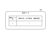
- FIG. 9A is an example of the setting data D01 of the irradiation scene, and shows an example of the setting data held for each sterilization device 1 that simultaneously irradiates ultraviolet rays.
- an irradiation scene ID for identifying an irradiation scene and an irradiation direction (horizontal angle, vertical angle) of ultraviolet rays are set.
- a plurality of sterilizers 1 that simultaneously irradiate the same target with ultraviolet rays are associated through the irradiation scene ID of the setting data D01, and therefore are indirectly associated as a group.
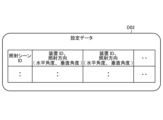
- FIG. 9B is an example of the setting data D02 of the irradiation scene, and shows an example of the setting data held in the sterilizer 1 or the control device 500, which is a master that manages a plurality of sterilizers 1.
- the irradiation scene ID that identifies the irradiation scene and the irradiation direction (horizontal angle, vertical angle) of the ultraviolet rays for each sterilizer 1 that simultaneously irradiates ultraviolet rays are set, and multiple The sterilizer 1 is directly associated as a group with the irradiation scene ID of the setting data D02.
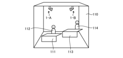
- FIG. 10A is a diagram showing an example of a space in which a plurality of sterilizers 1 (1-A, 1-B) are installed.
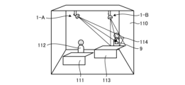
- FIG. 10B is a diagram illustrating an example of setting the first irradiation scene.
- FIG. 10C is a diagram illustrating an example of setting the second irradiation scene.
- the marker 9 is placed at the position of the person 112 as shown in FIG. 10B, and the process as shown in FIG.
- the device 1-A and the sterilizing device 1-B simultaneously irradiate ultraviolet rays, and the respective irradiation directions are set as the first irradiation scene in the setting data D01 or the setting data D02.
- the marker 9 is placed at the position of the person 114 as shown in FIG. 10C, and the processing as shown in FIG. 8 is performed.
- the sterilizer 1-A and the sterilizer 1-B simultaneously irradiate ultraviolet rays, and the respective irradiation directions are set as the second irradiation scene in the setting data D01 or the setting data D02.
- the marker 9 is provided with an ultraviolet sensor 92 (FIG. 1), which detects that the marker 9 is irradiated with ultraviolet light (that the optical axis of the light source section 21 is directed toward the marker 9), and operates the marker 9. - The user can be informed of this via the display section 94.
- an ultraviolet sensor 92 FIG. 1
- the main body 2 is provided with a visible light source section 7 (FIG. 1) that emits visible light along the same optical axis as the light source section 21, so that the user can move from the visible light irradiation position to the ultraviolet irradiation position. can be determined directly by visual inspection.
- a visible light source section 7 FIG. 1 that emits visible light along the same optical axis as the light source section 21, so that the user can move from the visible light irradiation position to the ultraviolet irradiation position. can be determined directly by visual inspection.
- FIG. 11 is a diagram showing an example of the setting data D1.
- the setting data D1 is divided into a plurality of time periods for each date in consideration of the irradiation area, season, and day of the week, and an irradiation scene ID and an exposure amount limit value are set for each time period.
- the irradiation scene ID is information for identifying an irradiation scene, and is the same as that set in the setting data D01 in FIG. 9A and the setting data D02 in FIG. 9B.
- the limit value of the exposure amount corresponds to the limit value of the exposure amount of ultraviolet rays adjusted by the value based on the number of multiple sterilizers 1 that simultaneously irradiate the same target with ultraviolet rays (irradiation scene). It is attached. More specifically, when the same target is uniformly and simultaneously irradiated with ultraviolet rays from multiple sterilizers 1, the limit value of the exposure amount is determined by dividing the allowable limit value of the amount of ultraviolet ray exposure within a predetermined period by the number of units. This is the value.
- the permissible limit value for the amount of exposure to ultraviolet light with a wavelength of 222 nm is such that the total value for all time periods is, for example, 22 mJ/cm 2 for 8 hours a day as specified by the Japanese Industrial Standard JIS Z 8812-1987. It is defined as follows. Further, as described above, when the human sensor 301 detects a person, the on/off duty of ultraviolet irradiation is controlled based on the distance to the person measured by the distance sensor 302, and When irradiation is performed for 8 hours, in the above example, it is controlled to be less than 22 mJ/cm 2 (for example, 20 mJ/cm 2 ). When a person is irradiated with ultraviolet rays, the amount of exposure to ultraviolet rays is accumulated, and when a limit value is reached, irradiation of ultraviolet rays is stopped.
- FIG. 12 is a flowchart showing an example of control by the control unit 52 of the control device 5, the control unit 12 of the terminal 10, or the control unit 502 of the control device 500.
- control unit 52 of the control device 5 when the control unit 52 of the control device 5 starts processing, it acquires the date from the internal clock function and acquires the corresponding setting data D1 (FIG. 11) (step S101).
- Step S102 when the current time enters the most recently started time period in the setting data D1, the control unit 52 and the like of the control device 5 starts irradiating ultraviolet rays in the irradiation direction of the first irradiation scene in that time period ( Step S102).
- the irradiation direction of the sterilizer 1 that simultaneously irradiates the same object with ultraviolet rays is set according to the setting data D01 in FIG. 9A or the setting data D02 in FIG. 9B.
- control unit 52 of the control device 5 determines whether or not the user or the like has given an instruction to stop the operation (step S103).
- control unit 52 and the like of the control device 5 determine that the user or the like has given an instruction to stop the operation (Yes in step S103)
- the control unit 52 and the like stop the operation (step S104) and end the process.
- control unit 52 and the like of the control device 5 determine that the user or the like has not given an instruction to stop the operation (No in step S103)
- the control unit 52 and the like of the control device 5 determine whether or not the current time period has ended (step S105). .
- the control unit 52 of the control device 5 determines that the current time period has ended (Yes in step S105)
- control unit 52 of the control device 5 determines whether the integrated value of the exposure amount in the current irradiation scene has reached the limit value of the exposure amount in the current irradiation scene (step S108).
- the control unit 52 and the like of the control device 5 determine that the limit value of the exposure amount for the current irradiation scene has not been reached (No in step S108)
- the process returns to the determination to stop operation (step S103).
- control unit 52 of the control device 5 determines whether there is a next irradiation scene in the current time period (step S110).
- control unit 52 of the control device 5 determines that there is the next irradiation scene (Yes in step S110)
- it starts irradiating ultraviolet rays in the irradiation direction of the next irradiation scene (step S111), and determines whether to stop the operation. Return to (step S103).
- control unit 52 of the control device 5 determines that there is no next irradiation scene (No in step S110), it waits for the start of the next time period (step S102).
- the process is assumed to start at a certain point on the date, but the process may always continue and control may be performed according to the setting data D1 corresponding to the date.
- FIG. 13 is a diagram showing an example of sensing timing by the ranging sensor 302.
- a TOF (Time of Flight) type sensor is used as the distance measurement sensor 302
- sensing is performed at the same time, interference may occur and accurate distance measurement may not be performed, so the sensing timing may be shifted. I have to.
- FIG. 13 when there are five sterilization devices 1 that simultaneously irradiate the same target, sensing is performed in the order of device ID: 75 ⁇ device ID: 68 ⁇ device ID: 97 ⁇ device ID: 43 ⁇ device ID: 55. That's what I do.
- the sterilization system includes a light source unit that irradiates ultraviolet rays with wavelengths that have little effect on the human body, and a horizontal angle of the light source unit that can be adjusted by rotating the light source unit in the horizontal direction.
- a vertical angle adjustment section that adjusts the vertical angle of the light source section by rotating the horizontal angle adjustment section and/or the light source section in the vertical direction, and a rotation of the horizontal angle adjustment section and/or the vertical angle adjustment section.
- the sterilizer is equipped with a plurality of sterilizers, each of which has a control device that controls the movement and irradiates the object with ultraviolet rays from a light source, and each of the control devices has setting data that includes the irradiation direction for simultaneously irradiating the same object with ultraviolet rays.
- the limit value of the exposure amount of ultraviolet rays is adjusted based on the value based on the number of multiple sterilizers that simultaneously irradiate ultraviolet rays to the same target by controlling the rotation of the horizontal angle adjustment part and/or the vertical angle adjustment part based on the
- the irradiation of ultraviolet rays is controlled based on the This makes it possible to enhance the bactericidal effect while ensuring safety for humans.
- the exposure limit value is adjusted depending on the number of simultaneous irradiation units, ensuring safety for humans.
- the control device controls the on/off duty of ultraviolet irradiation based on the distance to the person measured by the distance sensor, and Accumulate the amount of ultraviolet radiation exposure. This can improve safety for people.
- the sensing timing of the ranging sensors is shifted so that measurements are taken at the same time and interference does not occur. This allows accurate distance measurement.
- the limit value is the value obtained by dividing the allowable limit of the amount of ultraviolet ray exposure within a specified period by the number of sterilizers. If ultraviolet rays are not irradiated equally and simultaneously from the device to the same target, the permissible limit value for sterilization devices with a relatively low irradiation amount is a value divided by a value smaller than the number of units, and the irradiation amount is relatively high. For sterilizers, the allowable limit value is divided by a value greater than the number of units. This makes it possible to ensure safety for people and to perform appropriate control according to the number of sterilizers and the environment.
- the limit value is a value obtained by dividing the allowable limit value of the amount of ultraviolet ray exposure within a predetermined period by a value larger than the number of units.
- a light source unit that irradiates ultraviolet rays with a wavelength that has little effect on the human body, and a horizontal angle adjustment unit and/or a light source unit that adjusts the horizontal angle of the light source unit by rotating the light source unit in the horizontal direction.
- the vertical angle adjustment section that adjusts the vertical angle of the light source section, and the rotation of the horizontal angle adjustment section and/or the vertical angle adjustment section are controlled, and the light source section and a control device that irradiates ultraviolet rays, and when multiple sterilizers operate cooperatively, the control device controls the horizontal angle adjustment unit and/or Or, by controlling the rotation of the vertical angle adjustment part, the irradiation of ultraviolet rays is controlled based on the limit value of the amount of ultraviolet ray exposure adjusted by the value based on the number of multiple sterilizers that simultaneously irradiate the same target with ultraviolet rays. do. Thereby, it can be configured as a sterilization device.
- a light source unit that irradiates ultraviolet rays with a wavelength that has little effect on the human body and a horizontal angle adjustment unit and/or a light source unit that adjusts the horizontal angle of the light source unit by rotating the light source unit in the horizontal direction.
- the vertical angle adjustment section that adjusts the vertical angle of the light source section, and the rotation of the horizontal angle adjustment section and/or the vertical angle adjustment section are controlled, and the light source section
- a control device that irradiates ultraviolet rays, and a horizontal angle adjustment unit and/or vertical angle adjustment unit based on setting data including the irradiation direction to simultaneously irradiate the same target with ultraviolet rays when multiple sterilizers work together.
- the present invention is not limited to the above embodiments.
- the present invention also includes configurations in which the above-mentioned components are appropriately combined. Moreover, further effects and modifications can be easily derived by those skilled in the art. Therefore, the broader aspects of the present invention are not limited to the embodiments described above, and various modifications are possible.
Landscapes
- Health & Medical Sciences (AREA)
- Epidemiology (AREA)
- Life Sciences & Earth Sciences (AREA)
- Animal Behavior & Ethology (AREA)
- General Health & Medical Sciences (AREA)
- Public Health (AREA)
- Veterinary Medicine (AREA)
- Apparatus For Disinfection Or Sterilisation (AREA)
Abstract
実施形態の殺菌システムは、光源部(21)と、水平角度調整部(4)および/または垂直角度調整部(3)と、制御装置(5)とを有する殺菌装置(1)を複数備える。前記光源部(21)は、人体への影響が少ない波長の紫外線を照射する。前記水平角度調整部(4)は、前記光源部(21)を水平方向に対して回動することで、前記光源部(21)の水平角度を調整する。前記垂直角度調整部(3)は、前記光源部(21)を垂直方向に対して回動することで、前記光源部(21)の垂直角度を調整する。前記制御装置(5)は、前記水平角度調整部(4)および/または前記垂直角度調整部(3)の回動を制御し、対象物に前記光源部(21)による紫外線を照射する。前記制御装置(5)のそれぞれは、同一対象へ紫外線を同時照射するための照射方向を含む設定データに基づいて前記水平角度調整部(4)および/または前記垂直角度調整部(3)の回動を制御し、同一対象へ紫外線を同時照射する複数の前記殺菌装置(1)の台数を基準にした値により調整された紫外線の曝露量の制限値に基づいて紫外線の照射を制御する。
Description
本発明は、殺菌システム、殺菌装置および制御方法に関する。
従来から、所定の波長範囲(例えば、約190nm~約230nm)の紫外線が人(皮膚、目等)への影響が少ないことが知られており、ヒト細胞を害することなくバクテリアの殺菌を行うものが提案されている(例えば、特許文献1等を参照)。人への影響が少ない波長範囲の紫外線によれば、人のいる環境下においても殺菌が行えるため、夜間等の終業後に使用が限られることがなくなり、運用上および殺菌の効果上、有利である。
ただし、人への影響が少ない波長範囲であっても、長時間や多量の曝露は人の健康を害する恐れがあるため、米国労働衛生専門官会議(ACGIH:American Conference of Governmental Industrial Hygienists)により規定された値を元に日本工業規格 JIS Z 8812-1987(有害紫外放射の測定方法)では、例えば、222nmの波長の場合、1日8時間において22mJ/cm2という許容限界値が定められている。このような制限を守るため、人体への紫外線の許容積算光量を超えないように、紫外線の波長に応じた所定時間の照射を行った後、紫外線の照射を停止するように制御する装置が提案されている(例えば、特許文献2等を参照)。
一方、複数の殺菌装置が設けられることで、紫外線の照射範囲が重複する場合がある(例えば、特許文献3、4等を参照)。この場合、個々の殺菌装置において上述の許容限界値が守られるような制御が仮に行われていたとしても、紫外線の照射範囲が重複するエリアに居る人に対しては二重・三重・・に紫外線の曝露があるため、合計の曝露量が許容限界値を超えてしまうおそれがある。そのため、知識を持った者が殺菌装置の配置を調整し、できるだけ紫外線の照射範囲が重複しないようにすることが必要になる。
また、例えば222nmの紫外線は、たとえ髪の毛であっても紫外線が当たらなかった裏側等への殺菌効果はほとんどなく、殺菌効果を高める観点からは複数の殺菌装置からの異なった方向からの紫外線の照射が望まれる。しかし、前述のように、殺菌装置に許容限界値を守るような制御機構が仮に設けられていたとしても、複数の殺菌装置からの紫外線の照射が行われる場合、人への許容積算光量を超えてしまう場合があり、安全性の観点から問題があった。
上述のように、殺菌効果を高めることと、人への安全性を担保することの両立が難しく、その解決が求められていた。
本発明は、上記に鑑みてなされたものであって、殺菌効果を高めつつ、人への安全性を担保することができる殺菌システム、殺菌装置および制御方法を提供することを目的とする。
上述した課題を解決し、目的を達成するために、本発明の一態様に係る殺菌システムは、光源部と、水平角度調整部および/または垂直角度調整部と、制御装置とを有する殺菌装置を複数備える。前記光源部は、人体への影響が少ない波長の紫外線を照射する。前記水平角度調整部は、前記光源部を水平方向に対して回動することで、前記光源部の水平角度を調整する。前記垂直角度調整部は、前記光源部を垂直方向に対して回動することで、前記光源部の垂直角度を調整する。前記制御装置は、前記水平角度調整部および/または前記垂直角度調整部の回動を制御し、対象物に前記光源部による紫外線を照射する。前記制御装置のそれぞれは、同一対象へ紫外線を同時照射するための照射方向を含む設定データに基づいて前記水平角度調整部および/または前記垂直角度調整部の回動を制御し、同一対象へ紫外線を同時照射する複数の前記殺菌装置の台数を基準にした値により調整された紫外線の曝露量の制限値に基づいて紫外線の照射を制御する。
本発明の一態様に係る殺菌システムは、殺菌効果を高めつつ、人への安全性を担保することができる。
以下、実施形態に係る殺菌システム、殺菌装置および制御方法について図面を参照して説明する。なお、この実施形態によりこの発明が限定されるものではない。また、図面における各要素の寸法の関係、各要素の比率などは、現実と異なる場合がある。図面の相互間においても、互いの寸法の関係や比率が異なる部分が含まれている場合がある。また、1つの実施形態や変形例に記載された内容は、原則として他の実施形態や変形例にも同様に適用される。
<装置構成、システム構成>
図1は、一実施形態に係る殺菌装置1等の構成例を示すブロック図である。図1において、殺菌装置1は、例えば天井を構成する天井壁100にベース部41が取り付けられており、光源部21を有する本体部2と、本体部2を回動可能に支持する垂直角度調整部3および水平角度調整部4と、制御装置5とを備えている。
図1は、一実施形態に係る殺菌装置1等の構成例を示すブロック図である。図1において、殺菌装置1は、例えば天井を構成する天井壁100にベース部41が取り付けられており、光源部21を有する本体部2と、本体部2を回動可能に支持する垂直角度調整部3および水平角度調整部4と、制御装置5とを備えている。
なお、図1におけるX方向は水平方向であり、殺菌装置1の図示の状態における前後方向である。Y方向は水平方向であり、殺菌装置1の図示の状態における幅方向である。Z方向は水平方向と直交する垂直方向であり、殺菌装置1の上下方向である。なお、本実施形態においては、Z方向が殺菌対象空間Sの鉛直方向と平行であるが、これに限定されるものではなく、Z方向が鉛直方向に対して傾斜、あるいはZ方向が鉛直方向と直交する方向と平行であってもよい。
制御装置5は、殺菌装置1を制御するものである。制御装置5は、光源部21、垂直角度調整部3および水平角度調整部4を制御するものであり、ベース部41の内部空間に収容されている。制御装置5は、通信部51、制御部52、光源部駆動回路53、第1モータ駆動回路54、第2モータ駆動回路55を有する。制御装置5は、電源200から供給された電力に基づき、光源部21による紫外線の点灯・消灯、照射強度の調整、垂直角度調整部3による光源部21の垂直角度の調整、水平角度調整部4による光源部21の水平角度の調整などを行う。なお、制御装置5のハードウェア構成は、一般的な制御装置のハードウェア構成と同様である。また、電源200は、商業電源、発電機、バッテリなどである。
通信部51は、ユーザが所持する端末10との間で情報を送受信するものであり、例えば、端末10からの操作情報を受信したり、殺菌装置1の状態、光源部21の照射状態(例えば、点灯・消灯、照射強度)、光源部21の姿勢状態(例えば、垂直角度および水平角度)を端末10に送信したりするものである。通信部51は、例えば、Wi-Fi(登録商標)やBluetooth(登録商標)等の近距離無線通信を行うものである。
制御部52は、光源部21に対する照射制御、第1モータ32に対する駆動制御および第2モータ42に対する駆動制御などを行うものである。ここで、照射制御には、光源部21の点灯・消灯制御、照射強度制御などが含まれる。
光源部駆動回路53は、制御部52からの光源部21に対する照射制御信号に基づき、光源部21に電力を供給するものである。光源部駆動回路53は、光源部21が紫外線の照射強度を変更できるタイプである場合、照射強度の調整も行う。光源部駆動回路53は、紫外線照射のオン・オフのデューティーを調整して照射量の調整を行う。光源部駆動回路53は、制御部52および光源部21と電気的に接続されている。なお、光源部駆動回路53は、制御装置5が有しているが、これに限定されるものではなく、光源部21が有していてもよい。また、光源部21が異なる波長領域の光源が組み合わされた光源であった場合、それぞれの光源の照射強度を調整できるように調整を行う。
第1モータ駆動回路54は、制御部52からの第1モータ32に対する駆動制御信号に基づき、第1モータ32に対して駆動電力を供給することで、光源部21を垂直方向において回動させるものである。第1モータ駆動回路54は、制御部52および第1モータ32と電気的に接続されている。なお、第1モータ駆動回路54は、制御装置5が有しているが、これに限定されるものではなく、第1モータ32が有していてもよい。
第2モータ駆動回路55は、制御部52からの第2モータ42に対する駆動制御信号に基づき、第2モータ42に対して駆動電力を供給することで、光源部21を水平方向において回動させるものである。第2モータ駆動回路55は、制御部52および第2モータ42と電気的に接続されている。なお、第2モータ駆動回路55は、制御装置5が有しているが、これに限定されるものではなく、第2モータ42が有していてもよい。
端末10は、ユーザが操作することで殺菌装置1を操作するものであるとともに、ユーザが殺菌装置1の状態を把握するものである。端末10は、通信部11と、制御部12と、操作・表示部13とを有する。なお、端末10は、殺菌装置1用の専用端末であってもよいし、スマートフォン、タブレット、ノートパソコンなどの汎用端末であってもよい。また、端末10のハードウェア構成は、一般的な端末のハードウェア構成と同様である。
通信部11は、制御装置5との間で情報を送受信するものである。通信部11は、例えば、Wi-Fi(登録商標)やBluetooth(登録商標)等の近距離無線通信を行うものである。なお、情報の送受信は無線に限られるものではなく、有線によるものであってもよい。
制御部12は、端末10を制御するものであり、少なくとも操作・表示部13に対するユーザの操作に基づいて、操作情報を通信部11に出力するものである。制御部12は、操作・表示部13による表示も制御する。制御部12は、通信部11および操作・表示部13と電気的に接続されている。なお、制御部12は、自装置側の通信部11および殺菌装置1側の通信部51を介して接続された制御部52の処理の一部を代行することができる。
操作・表示部13は、端末10における一般的な操作および表示のほかに、殺菌装置1を遠隔操作する際に用いられるものである。操作・表示部13は、図示はしないが例えば、紫外線の点灯・消灯に対応するスイッチ、照射強度に対応するスイッチ、光源部21の垂直角度の調整に対応するスイッチ、光源部21の水平角度の調整に対応するスイッチなどが含まれる。なお、スイッチは、通電・非通電や抵抗変化などの機械式のスイッチであっても、タッチパネルなどの電気式のスイッチであってもよい。
また、本体部2の近傍にはCMOS(Complementary Metal Oxide Semiconductor)センサ等のマーカセンサ6が設けられている。マーカセンサ6は、マーカ9から発せられる赤外線(赤外光)等によるマーカ信号を2次元画像上で検出する。制御部52は、マーカセンサ6の検出信号(画像信号)から、マーカ9の位置を認識し、マーカ9に紫外線の照射方向を向け、殺菌のために紫外線を照射する位置や範囲の設定を行う。
マーカ9は、信号送信部91と、紫外線センサ92と、制御部93と、操作・表示部94とを備えている。紫外線センサ92は省略される場合もある。信号送信部91は、例えば、赤外線によるマーカ信号を送信する機能を有している。なお、マーカ信号は、パルスパターンを変えることで、マーカ9が複数ある場合に、それぞれのマーカ9から送信されるマーカ信号を識別することができるようになっている。
紫外線センサ92は、殺菌装置1の光源部21から照射される紫外線を検出する機能を有している。すなわち、マーカ9が殺菌装置1による紫外線の照射範囲内にあることを紫外線センサ92により知ることができる。
制御部93は、マーカ9を制御するものであり、信号送信部91によるマーカ信号の送信、紫外線センサ92による紫外線の検出の確認等の制御を行う。操作・表示部94は、ユーザによる操作を受け付け、ユーザに対する状態の表示等を行う。
また、殺菌装置1の本体部2には、光源部21による紫外線の照射方向に対して平行に可視光を照射する可視光源部7が設けられている。可視光源部7は、光源部駆動回路53を介して制御部52によって点灯・消灯が制御される。
また、ベース部41等には7セグメントLED等による表示部8が設けられており、制御部52によって表示が制御される。表示部8による表示内容には、光源部21の寿命や、殺菌装置1におけるエラー情報が含まれる。
また、殺菌装置1の本体部2の近傍には、人感センサ301や測距センサ302が設けられている。人感センサ301は紫外線の照射方向の人等の体温を有する物体が存在するか否かを検知する装置であり、例えばサーモパイル型センサが用いられる。測距センサ302は紫外線の照射方向に存在する人等との距離を測定する装置であり、例えばレーダセンサが用いられる。測距センサ302は、ステレオカメラや単眼カメラ+画像処理(深層学習)によっても実現が可能である。制御部52は、人感センサ301が人を検知している場合に、測距センサ302により測定された人との距離に基づいて紫外線照射のオン・オフのデューティーを制御するとともに、所定期間内の紫外線の曝露量を積算する。なお、マーカセンサ6、人感センサ301、測距センサ302と殺菌装置1との接続は有線であっても無線であってもよい。
図2は、複数の殺菌装置1等が含まれる場合の構成例を示す図である。図2において、例えば天井を構成する天井壁100に複数の殺菌装置1が取り付けられている。各殺菌装置1の制御装置5は、それぞれが対等な関係で制御を行うか、いずれかがマスターとなって統括的に制御を行う。また、殺菌装置1の制御装置5とは別に、統括制御用の制御装置500が設けられるものであってもよい。制御装置500は、通信部501と、制御部502と、操作・表示部503とを備えている。
通信部501は、各殺菌装置1の制御装置5との間で情報を送受信するものである。通信部501は、例えば、Wi-Fi(登録商標)やBluetooth(登録商標)等の近距離無線通信を行うものである。なお、情報の送受信は無線に限られるものではなく、有線によるものであってもよい。
制御部502は、制御装置500を制御するものであり、少なくとも操作・表示部503に対するユーザの操作または予め設定された情報に基づいて、操作情報を通信部501に出力するものである。制御部502は、通信部501および操作・表示部503と電気的に接続されている。
操作・表示部503は、制御装置500における一般的な操作および表示のほかに、各殺菌装置1を遠隔操作する際に用いられるものである。操作・表示部503は、図示はしないが例えば、紫外線の点灯・消灯に対応するスイッチ、照射強度に対応するスイッチ、光源部21の垂直角度の調整に対応するスイッチ、光源部21の水平角度の調整に対応するスイッチ、各種自動動作の設定のためのスイッチなどが含まれる。なお、スイッチは、通電・非通電や抵抗変化などの機械式のスイッチであっても、タッチパネルなどの電気式のスイッチであってもよい。
端末10は、各殺菌装置1の制御装置5との間、マスターに設定された制御装置5との間、または、制御装置500との間で通信を行い、ユーザによる各種の操作や、状態の確認に対応する。端末10は、制御装置500とともに、または、制御装置500に代わって、個々の殺菌装置1を制御することができる。
図3は、殺菌装置1の一例(殺菌装置1A)の機械的な構成例を示す斜視図である。殺菌装置1Aは、図3に示されるように、紫外線UVを殺菌対象空間Sに照射するものである。殺菌装置1Aは、殺菌対象空間Sの一部を構成する壁、本実施形態では天井を構成する天井壁100に取り付けられている。具体的には、殺菌装置1Aは、天井壁100から殺菌対象空間Sに突出した状態で天井壁100に対して、図示しないレール等を介して取り付けられている。殺菌装置1Aは、光源部21が取り付けられる本体部2と、垂直角度調整部3と、水平角度調整部4と、制御装置5とを備える。
本体部2は、光源部21が取り付けられるものである。本体部2は、略円筒形状に形成されており、軸方向のうち、殺菌対象空間S側に開口22が形成され、殺菌対象空間Sと反対側が閉塞されている。本体部2は、図示しない支持軸を介して、垂直角度調整部3に対して回転自在に支持されている。
光源部21は、放射状の紫外線UVを殺菌対象空間Sに対して照射するものである。光源部21は、本体部2の内部空間のうち、本体部2の軸方向において開口22と対向した位置に取り付けられている。光源部21は、開口22を介して紫外線UVを殺菌対象空間Sに照射する。
ここで、光源部21が殺菌対象空間Sに照射する紫外線UVは、可視光線とは異なる波長の電磁波であり、本実施形態では、人体への影響が少ない222nmを中心とした波長の電磁波をいう。すなわち、190nm未満の紫外線は、空気、特に空気中の酸素に吸収されるため、殺菌対象空間Sに存在する物体、例えば人体まで到達する線量が大幅に減少してしまい、物体に対する殺菌効果が減少する。一方、230nmを超える紫外線は、殺菌対象空間Sに存在する物体が人体の場合に、細胞に吸収され細胞内のDNAに損傷を与える可能性がある。本実施形態における光源部21は、例えば、222nmにピークを有するKrClエキシマランプを光源として有し、人体に悪影響を及ぼす波長がカットされたものである。また、放射状の紫外線UVは、光源から出射する紫外線が放射状であってもよいし、光源から出射する紫外線UVは直線状であって、図示しないレンズにより実現してもよい。
また、光源部21は、1つの波長領域の紫外線UVを照射する光源に限られず、波長領域の異なる紫外線UVを切り替えられるものであってもよい。また、光源部21は、1つの波長領域の紫外線を照射する光源と、それとは異なる波長領域の紫外線を照射する光源とが組み合わされたものであってもよい。具体的には、190nm~230nmの波長の紫外線を照射する光源と、230nmを超える波長の紫外線を照射する光源とが組み合わされたものでもよい。
垂直角度調整部3は、光源部21を垂直方向Zにおいて回動することで、垂直角度を調整、すなわちチルト方向Tを調整する。垂直角度調整部3は、アーム部31と、第1モータ32とを有する。アーム部31は、本体部2を垂直方向Zに回動可能に支持するものである。アーム部31は、下方向に開口するU字状に形成されており、開口を形成する両先端部31a、31aにおいて、本体部2が両先端部31a、31aの対向方向周りに回転自在に支持されている。第1モータ32は、垂直アクチュエータであり、本体部2をアーム部31に対して回動させるものである。第1モータ32は、アーム部31に取り付けられており、図示しない駆動機構を介して、支持軸周り、すなわち対向方向周りに本体部2を回動させるものである。本実施形態における光源部21は、第1モータ32により、下方向を0度とした場合に、例えば、±90度の範囲で揺動させる。垂直角度調整部3は、図示しない支持軸を介して、水平角度調整部4に対して回転自在に支持されている。
水平角度調整部4は、光源部21を水平方向(前後方向X、幅方向Y)において回動することで、水平角度を調整、すなわちパン方向Pを調整する。水平角度調整部4は、ベース部41と、第2モータ42とを有する。ベース部41は、アーム部31を介して本体部2を水平方向に回動可能に支持するものである。ベース部41は、天井壁100に取り付けられており、前後方向を長手方向として立方体状に形成されており、アーム部31の上方向側の先端部31bにおいてアーム部31が垂直方向Z周りに回転自在に支持されている。第2モータ42は、水平アクチュエータであり、アーム部31をベース部41に対して回動させるものである。第2モータ42は、ベース部41に取り付けられており、図示しない駆動機構を介して、支持軸周り、すなわち垂直方向周りにアーム部31を回動させることで、本体部2を回動させるものである。本実施形態における光源部21は、第2モータ42により、水平方向のうち、任意の方向を0度とした場合に、例えば、±180度の範囲で揺動させる。
なお、上記の説明においては、各アクチュエータをモータとしたが、これに限定されるものではなく、液圧式シリンダ、気圧式シリンダなどであってもよい。
図4は、殺菌装置1の他の例(殺菌装置1B)の機械的な構成例を示す斜視図である。図4において、殺菌装置1Bは、天井壁100に対する取り付け状態の点で、前述の殺菌装置1Aと異なる。殺菌装置1Bの基本的構成は、殺菌装置1Aの基本的構成と同一、またはほぼ同一であるので、同一符号についてはその説明を省略あるいは簡略化する。
殺菌装置1Bは、図4に示されるように、紫外線UVを殺菌対象空間Sに照射するものである。殺菌装置1Bは、殺菌対象空間Sの一部を構成する天井壁100に取り付けられている。具体的には、殺菌装置1Bは、天井壁100から殺菌対象空間S側と反対側に突出、すなわち天井壁100に埋設した状態で天井壁100に取り付けられている。天井壁100には、開口101が形成されており、殺菌装置1B、特に本体部2の開口22が開口101を介して、殺菌対象空間Sに露出して取り付けらえている。殺菌装置1Bは、光源部21を取り付けられる本体部2と、垂直角度調整部3と、水平角度調整部4と、制御装置5とを備える。
本体部2は、放射状の紫外線UVを殺菌対象空間Sに対して照射する光源部21が取り付けられるものである。本体部2は、略円筒形状に形成されており、軸方向のうち、殺菌対象空間S側に開口22が形成され、殺菌対象空間S側と反対側が閉塞されている。本体部2は、図示しない支持軸を介して、垂直角度調整部3に対して回転自在に支持されている。
垂直角度調整部3は、光源部21を垂直方向Zにおいて回動することで、垂直角度を調整、すなわちチルト方向Tを調整する。垂直角度調整部3は、サブ枠部33と、第1モータ32とを有する。サブ枠部33は、本体部2を垂直方向Zに回動可能に支持するものである。サブ枠部33は、上下方向を軸とする円筒形状に形成され、上下方向に開口を介して外部連通する内部空間33aが形成されている。サブ枠部33は、内部空間33aにおいて、本体部2が水平方向周りに回動自在に支持されている。つまり、サブ枠部33は、本体部2の少なくとも一部が内部空間33aに収容され、かつ本体部2を垂直方向に回動可能に支持する。第1モータ32は、サブ枠部33に取り付けられており、図示しない駆動機構を介して、支持軸周りに本体部2を回動させるものである。本実施形態における光源部21は、第1モータ32により、下方向を0度とした場合に、例えば、-35度~+45度の範囲で揺動させる。
水平角度調整部4は、光源部21を水平方向(前後方向X、幅方向Y)において回動することで、水平角度を調整、すなわちパン方向Pを調整する。水平角度調整部4は、ベース枠部43と、第2モータ42とを有する。ベース枠部43は、サブ枠部33を介して本体部2を水平方向に回動可能に支持するものである。ベース枠部43は、上下方向において開口101と対向して天井壁100に取り付けられており、上下方向を軸とする円筒形状に形成され、上下方向に開口を介して外部連通する内部空間43aが形成されている。ベース枠部43は、内部空間43aにおいて、本体部2が垂直方向周りに回動自在に支持されている。つまり、ベース枠部43は、サブ枠部33の少なくとも一部が内部空間43aに収容され、かつサブ枠部33を垂直方向に回動可能に支持する。本実施形態における光源部21は、第2モータ42により、水平方向のうち、任意の方向を0度とした場合に、例えば、+355度の範囲で揺動させる。
なお、上記の説明においては、各アクチュエータをモータとしたが、これに限定されるものではなく、液圧式シリンダ、気圧式シリンダなどであってもよい。
図5は、殺菌装置1の他の外観例を示す図であり、図3の殺菌装置1Aに近似した構造を有している。図5において、ベース部41には表示部8が設けられている。本体部2の出射側には、中央に紫外線の照射窓23が設けられ、その周囲にマーカセンサ6、人感センサ301、測距センサ302が設けられている。
図6は、制御装置5の制御部52、端末10の制御部12、または、他の制御装置500の制御部502のハードウェア構成例を示す図である。図6において、制御部52、12、502は、一般的なコンピュータの構成を有しており、処理部(プロセッサ)H1と、記憶部(メモリ)H2と、入出力部(I/O:Input Output)H3とを備えている。記憶部H2には、ROM(Read Only Memory)、RAM(Random Access Memory)、NV-RAM(Nonvolatile-RAM)、SSD(Solid State Drive)、HDD(Hard Disk Drive)等が含まれる。
処理部H1は、記憶部H2に記憶されたプログラムに従い、記憶部H2に記憶されたデータまたは入出力部H3から入力されたデータに基づいて処理を行う。処理により得られたデータは、入出力部H3から出力される。
図7は、制御装置5の制御部52、端末10の制御部12、または、他の制御装置500の制御部502の機能構成例を示す図である。図7において、制御部52、12、502は、照射位置等設定部C1と、照射位置制御部C2と、照射制御部C3と、マーカ検出部C4と、寿命・エラー情報管理部C5と、表示制御部C6とを備えており、設定データD01、D02、D1の設定および参照を行う。
照射位置等設定部C1は、照射エリア、季節および曜日が考慮された日付ごと、時間帯ごとに、照射シーンと曝露量の制限値とを含む設定データD1の設定を行う機能を有する。照射シーンには、同一対象に紫外線を同時照射する複数の殺菌装置1を識別する情報と、各殺菌装置1から同一対象への照射方向(水平角度、垂直角度)とが対応付けられている。曝露量の制限値には、同一対象へ紫外線を同時照射する複数の殺菌装置1の台数を基準にした値により調整された紫外線の曝露量の制限値が対応付けられている。より具体的には、曝露量の制限値は、複数の殺菌装置1から同一対象へ紫外線が均等に同時照射される場合は、所定期間内の紫外線の曝露量の許容限界値が台数で除算された値である。また、複数の殺菌装置1から同一対象へ紫外線が均等に同時照射されない場合は、照射量が相対的に少ない殺菌装置1については、許容限界値が台数より小さい値で除算された値であり、照射量が相対的に多い殺菌装置1については、許容限界値が台数より大きい値で除算された値である。また、暴露量を制限値に対してマージンをとりたい場合は、所定期間内の紫外線の曝露量の許容限界値が台数より大きい値で除算された値である。
照射位置制御部C2は、設定データD1と後述する設定データD01、D02とに基づいて殺菌装置1の垂直角度調整部3および水平角度調整部4を制御し、紫外線を照射する位置を制御する機能を有する。照射制御部C3は、設定データD1に基づいて紫外線の点灯・消灯、強度変更(光源により強度が変更できる場合とできない場合とがある)を行う機能を有する。その際、照射制御部C3は、人感センサ301が人を検知している場合に、測距センサ302により測定された人との距離に基づいて紫外線照射のオン・オフのデューティーを制御するとともに、所定期間内の紫外線の曝露量を積算する。
マーカ検出部C4は、マーカ9から送信される赤外線等によるマーカ信号をマーカセンサ6の検出信号(画像信号)から捕捉し、マーカ9に紫外線の照射方向が向く(追尾する)ように照射位置制御部C2に移動方向についての情報を与える。なお、複数のマーカ9が設けられる場合、各マーカ9のマーカ信号はパルスパターンが変えられているため、それぞれのマーカ9を識別することができる。
寿命・エラー情報管理部C5は、殺菌のための紫外線を照射する光源部21の寿命や殺菌装置1の動作中に発生したエラー情報を管理する機能を有している。表示制御部C6は、寿命・エラー情報管理部C5によって管理されている光源部21の寿命や殺菌装置1のエラー情報を表示部8によって表示する機能を有している。
<ユーザによるリアルタイムでの操作>
図1~図7において、ユーザは、端末10等を操作することで、殺菌装置1(1A、1B)の状態、光源部21の照射状態、光源部21の姿勢状態を変更する。例えば、制御装置5は、ユーザが端末10を操作することで、光源部21を点灯する場合に、点灯に対応する操作情報に対応する照射制御信号に基づき、光源部駆動回路53を介して、光源部21を点灯する。殺菌装置1は、光源部21が点灯されることで、放射状の紫外線UVが殺菌対象空間Sに照射され、殺菌対象空間Sの空気および殺菌対象空間Sに存在する物体を紫外線UVにより殺菌する。また、制御装置5は、ユーザが端末10を操作することで、殺菌対象空間Sにおける紫外線UVの照射範囲を垂直方向において変更する場合に、垂直角度の調整に対応する操作情報に対応する第1モータ32に対する駆動制御信号に基づき、第1モータ駆動回路54を介して、第1モータ32を駆動し、光源部21を垂直方向に回動させる。また、制御装置5は、ユーザが端末10を操作することで、殺菌対象空間Sにおける紫外線UVの照射範囲を水平方向において変更する場合に、水平角度の調整に対応する操作情報に対応する第2モータ42に対する駆動制御信号に基づき、第2モータ駆動回路55を介して、第2モータ42を駆動し、光源部21を水平方向に回動させる。つまり、ユーザが殺菌対象空間Sに存在する物体を殺菌したい場合は、光源部21を垂直方向および水平方向に回動させることで、光源部21の紫外線UVの照射範囲を物体にまで移動させて、殺菌を行う。
図1~図7において、ユーザは、端末10等を操作することで、殺菌装置1(1A、1B)の状態、光源部21の照射状態、光源部21の姿勢状態を変更する。例えば、制御装置5は、ユーザが端末10を操作することで、光源部21を点灯する場合に、点灯に対応する操作情報に対応する照射制御信号に基づき、光源部駆動回路53を介して、光源部21を点灯する。殺菌装置1は、光源部21が点灯されることで、放射状の紫外線UVが殺菌対象空間Sに照射され、殺菌対象空間Sの空気および殺菌対象空間Sに存在する物体を紫外線UVにより殺菌する。また、制御装置5は、ユーザが端末10を操作することで、殺菌対象空間Sにおける紫外線UVの照射範囲を垂直方向において変更する場合に、垂直角度の調整に対応する操作情報に対応する第1モータ32に対する駆動制御信号に基づき、第1モータ駆動回路54を介して、第1モータ32を駆動し、光源部21を垂直方向に回動させる。また、制御装置5は、ユーザが端末10を操作することで、殺菌対象空間Sにおける紫外線UVの照射範囲を水平方向において変更する場合に、水平角度の調整に対応する操作情報に対応する第2モータ42に対する駆動制御信号に基づき、第2モータ駆動回路55を介して、第2モータ42を駆動し、光源部21を水平方向に回動させる。つまり、ユーザが殺菌対象空間Sに存在する物体を殺菌したい場合は、光源部21を垂直方向および水平方向に回動させることで、光源部21の紫外線UVの照射範囲を物体にまで移動させて、殺菌を行う。
以上のように、本実施形態に係る殺菌装置1(1A、1B)は、光源部21が水平方向および垂直方向に回動させることができるので、光源部21が回動できない場合と比較して、殺菌対象空間Sに対する紫外線UVの照射範囲を広くすることができる。したがって、広範囲の殺菌対象空間Sを殺菌することができるので、簡便に空間における環境改善を図ることができる。
また、光源部21は、222nmを中心とする波長の電磁波である紫外線UVを照射するので、殺菌対象空間Sに人がいて、人に対して光源部21から紫外線UVが照射されていても、照射される紫外線が人体に対する影響が著しく低い。したがって、殺菌対象空間Sに人がいても、殺菌装置1による殺菌を安全に行える。
なお、上記の説明においては、ユーザが手動操作することで殺菌装置1(1A、1B)が動作するが、これに限定されるものではなく、自動操作により動作させることができる。例えば、物体の動きに反応するセンサ、例えば人感センサなどを用いて、物体の動きに連動して、紫外線UVの照射範囲が変化する連動モードを有しており、所定の物体、例えば、人がいる方向または人がいない方向に照射方向を連動させ、紫外線UVを照射してもよい。また、制御部52は、予め設定された動作、例えば殺菌対象空間Sを構成する床や壁の全域に紫外線UVが照射される殺菌モードを有したり、所定時間、例えば、殺菌対象空間Sに人がいない時間帯となると、紫外線UVを殺菌対象空間Sに照射したりしてもよい。
<照射シーンの設定>
複数の殺菌装置1から同一対象へ紫外線を同時照射する場合、照射対象ごとに各殺菌装置1の照射方向が照射シーンとして設定される。設定データは、紫外線を同時照射する殺菌装置1ごとに保持されるか、複数の殺菌装置1を管理するマスターとなる殺菌装置1または制御装置500において保持される。また、このような位置の設定はユーザが行う必要があることから、簡易に行えることが望まれる。
複数の殺菌装置1から同一対象へ紫外線を同時照射する場合、照射対象ごとに各殺菌装置1の照射方向が照射シーンとして設定される。設定データは、紫外線を同時照射する殺菌装置1ごとに保持されるか、複数の殺菌装置1を管理するマスターとなる殺菌装置1または制御装置500において保持される。また、このような位置の設定はユーザが行う必要があることから、簡易に行えることが望まれる。
図8は、マーカ9と、制御装置5の制御部52、端末10の制御部12、または、他の制御装置500の制御部502とによる制御例を示すフローチャートである。
図8において、処理を開始すると、マーカ9側ではマーカ信号の送信を開始し(ステップS11)、同一対象へ紫外線を同時照射する殺菌装置1の制御部52等ではマーカセンサ6の信号に基づいてスキャンを行う(ステップS12)。マーカセンサ6は、例えば、上下方向(Z軸方向)は全範囲をカバーしているが、左右方向(X軸方向、Y軸方向)は全範囲をカバーしていないため、制御部52等は、アーム部31の回転を行ってスキャンを行う。スキャンによりマーカセンサ6が捕捉された場合、本体部2の回転も行われ、光源部21の光軸はマーカセンサ6を向く。
次いで、制御部52等は、マーカ9からのマーカ信号を捕捉できたか否か判断し(ステップS13)、捕捉できていないと判断した場合(ステップS13のNo)は信号スキャン(ステップS12)から処理を繰り返す。
制御部52等は、マーカ9からのマーカ信号を捕捉できたと判断した場合(ステップS13のYes)、操作・表示部13、503等に位置の設定を行うか否かのメッセージ等を表示し、ユーザに設定の可否を求める(ステップS14)。
捕捉されている位置についてユーザが設定を望まない等により、ユーザから操作・表示部13、503等により設定が拒否されると(ステップS14のNo)、制御部52等は、ユーザにより設定処理の終了が指示されるか否か判断する(ステップS15)。制御部52等は、ユーザにより設定処理の終了が指示されていないと判断した場合(ステップS15のNo)、信号スキャン(ステップS12)から処理を繰り返す。制御部52等は、ユーザにより設定処理の終了が指示されていると判断した場合(ステップS15のYes)、処理を終了する。
制御部52等は、ユーザから操作・表示部13、503等により設定が許諾されると(ステップS14のYes)、現在の位置(水平角度、垂直角度)を設定(記憶)する(ステップS16)。
そして、制御部52等は、ユーザから操作・表示部13、503等により次の設定が要求されているか(次の設定が拒否されていないか)否か判断し(ステップS17)、要求されている(拒否されていない)と判断した場合(ステップS17のYes)、信号スキャン(ステップS12)から処理を繰り返す。
制御部52等は、次の設定が要求されていない(拒否されている)と判断した場合(ステップS17のNo)、処理を終了する。マーカ9においてもマーカ信号の送信を終了し(ステップS18)、処理を終了する。
図9Aは照射シーンの設定データD01の例であり、紫外線を同時照射する殺菌装置1ごとに保持される設定データの例を示している。この場合、照射シーンを識別する照射シーンIDと、紫外線の照射方向(水平角度、垂直角度)が設定されている。同一対象へ紫外線を同時照射する複数の殺菌装置1は、設定データD01の照射シーンIDを通して対応付けられるため、グループとして間接的に対応付けられる。
図9Bは照射シーンの設定データD02の例であり、複数の殺菌装置1を管理するマスターとなる殺菌装置1または制御装置500において保持される設定データの例を示している。この場合、照射シーンを識別する照射シーンIDと、紫外線を同時照射する殺菌装置1ごとの紫外線の照射方向(水平角度、垂直角度)が設定されており、同一対象へ紫外線を同時照射する複数の殺菌装置1は、設定データD02の照射シーンIDにグループとして直接に対応付けられる。
<照射シーンの設定の例>
図10Aは、複数の殺菌装置1(1-A、1-B)が設置された空間の例を示す図である。図10Bは、第1の照射シーンの設定の例を示す図である。図10Cは、第2の照射シーンの設定の例を示す図である。
図10Aは、複数の殺菌装置1(1-A、1-B)が設置された空間の例を示す図である。図10Bは、第1の照射シーンの設定の例を示す図である。図10Cは、第2の照射シーンの設定の例を示す図である。
図10Aの状態において、人112を中心とする第1の照射シーンを設定する場合、図10Bのように人112の位置にマーカ9を配置し、図8のような処理を行うことで、殺菌装置1-Aと殺菌装置1-Bとが紫外線の同時照射を行い、それぞれの照射方向が第1の照射シーンとして設定データD01または設定データD02に設定される。同様に、図10Aの状態において、人114を中心とする第2の照射シーンを設定する場合、図10Cのように人114の位置にマーカ9を配置し、図8のような処理を行うことで、殺菌装置1-Aと殺菌装置1-Bとが紫外線の同時照射を行い、それぞれの照射方向が第2の照射シーンとして設定データD01または設定データD02に設定される。
<設定における紫外線の可視化>
制御部52等により殺菌装置1がマーカ9を正常に捕捉し、紫外線の照射範囲がマーカ9を向いていると信じることができれば問題はないが、ユーザによっては本当に紫外線の照射範囲がマーカ9を向いていることを確認したい場合がある。この場合、紫外線は直接には目視で確認することができないため、何らかの補助が必要になる。
制御部52等により殺菌装置1がマーカ9を正常に捕捉し、紫外線の照射範囲がマーカ9を向いていると信じることができれば問題はないが、ユーザによっては本当に紫外線の照射範囲がマーカ9を向いていることを確認したい場合がある。この場合、紫外線は直接には目視で確認することができないため、何らかの補助が必要になる。
本実施形態では、マーカ9に紫外線センサ92(図1)が設けられ、マーカ9に紫外線が照射されていること(マーカ9に光源部21の光軸が向いていること)を検出し、操作・表示部94を介してユーザに対してその旨を知らせることができる。
また、本体部2には、光源部21と同じ光軸に対して可視光を発する可視光源部7(図1)が設けられているため、ユーザは可視光の照射位置から、紫外線の照射位置を目視により直接に知ることができる。
<設定データに基づく処理例>
図11は、設定データD1の例を示す図である。設定データD1は、照射エリア、季節および曜日が考慮された日付ごとに複数の時間帯に分けられており、それぞれに、照射シーンIDと曝露量の制限値とが設定されている。照射シーンIDは照射シーンを識別する情報であり、図9Aの設定データD01や図9Bの設定データD02に設定されるものと同じである。照射シーンIDと曝露量の制限値との組は、任意の数とすることができる。例えば、その時間帯に紫外線の照射を行わない場合は、照射シーンIDと曝露量の制限値との組はなし(ゼロ組)とすることもできるし、1以上とすることもできる。
図11は、設定データD1の例を示す図である。設定データD1は、照射エリア、季節および曜日が考慮された日付ごとに複数の時間帯に分けられており、それぞれに、照射シーンIDと曝露量の制限値とが設定されている。照射シーンIDは照射シーンを識別する情報であり、図9Aの設定データD01や図9Bの設定データD02に設定されるものと同じである。照射シーンIDと曝露量の制限値との組は、任意の数とすることができる。例えば、その時間帯に紫外線の照射を行わない場合は、照射シーンIDと曝露量の制限値との組はなし(ゼロ組)とすることもできるし、1以上とすることもできる。
前述のように、曝露量の制限値には、同一対象へ紫外線を同時照射(照射シーン)する複数の殺菌装置1の台数を基準にした値により調整された紫外線の曝露量の制限値が対応付けられている。より具体的には、曝露量の制限値は、複数の殺菌装置1から同一対象へ紫外線が均等に同時照射される場合は、所定期間内の紫外線の曝露量の許容限界値が台数で除算された値である。また、複数の殺菌装置1から同一対象へ紫外線が均等に同時照射されない場合は、照射量が相対的に少ない殺菌装置1については、許容限界値が台数より小さい値で除算された値であり、照射量が相対的に多い殺菌装置1については、許容限界値が台数より大きい値で除算された値である。また、暴露量を制限値に対してマージンをとりたい場合は、所定期間内の紫外線の曝露量の許容限界値が台数より大きい値で除算された値である。
ここで、222nmの波長の紫外線の曝露量の許容限界値は、全時間帯の合計値が、例えば、日本工業規格 JIS Z 8812-1987により規定された1日8時間において22mJ/cm2となるように定められている。また、前述のように、人感センサ301が人を検知している場合に、測距センサ302により測定された人との距離に基づいて紫外線照射のオン・オフのデューティーが制御され、1日8時間の照射が行われた場合に、上述の例では22mJ/cm2未満(例えば、20mJ/cm2)に制御される。紫外線が人に照射される場合、紫外線の曝露量は積算され、制限値に達した場合には紫外線の照射が停止される。
図12は、制御装置5の制御部52、端末10の制御部12、または、制御装置500の制御部502による制御例を示すフローチャートである。
図12において、制御装置5の制御部52等は、処理を開始すると、内部の時計機能から日付を取得し、対応する設定データD1(図11)を取得する(ステップS101)。
次いで、制御装置5の制御部52等は、現在時刻が設定データD1での直近に開始される時間帯に入ったら、その時間帯の最初の照射シーンの照射方向に紫外線の照射を開始する(ステップS102)。この際、図9Aの設定データD01または図9Bの設定データD02に従い、同一対象に紫外線を同時照射する殺菌装置1の照射方向が設定される。
次いで、制御装置5の制御部52等は、ユーザ等から運転停止の指示がされているか否か判断する(ステップS103)。制御装置5の制御部52等は、ユーザ等から運転停止の指示がされたと判断した場合(ステップS103のYes)、運転を停止し(ステップS104)、処理を終了する。
また、制御装置5の制御部52等は、ユーザ等から運転停止の指示がされていないと判断した場合(ステップS103のNo)、現在の時間帯が終了したか否か判断する(ステップS105)。制御装置5の制御部52等は、現在の時間帯が終了したと判断した場合(ステップS105のYes)、紫外線の照射を停止し(ステップS106)、次の時間帯の開始(ステップS102)を待機する。
また、制御装置5の制御部52等は、現在の時間帯が終了していないと判断した場合(ステップS105のNo)、人感センサ301により照射方向に人が検知されたら、測距センサ302により測定された距離に基づいて紫外線照射のオン・オフのデューティーを変え、曝露量を積算する(ステップS107)。
次いで、制御装置5の制御部52等は、現在の照射シーンにおける曝露量の積算値が、現在の照射シーンの曝露量の制限値に到達したか否か判断する(ステップS108)。制御装置5の制御部52等は、現在の照射シーンの曝露量の制限値に到達していないと判断した場合(ステップS108のNo)、運転停止の判断(ステップS103)に戻る。
また、制御装置5の制御部52等は、現在の照射シーンの曝露量の制限値に到達したと判断した場合(ステップS108のYes)、紫外線の照射を停止する(ステップS109)。なお、人以外への紫外線の同時照射についても照射量を管理し、照射量の積算値が所定値に到達した場合には、現在の照射シーンを終了させる。また、人以外への紫外線の同時照射については、人に照射する場合よりも照射量は大きく設定され、距離に基づいてデューティーを変える必要もない(距離に基づいてデューティーを変えてもよい)。
次いで、制御装置5の制御部52等は、現在の時間帯に次の照射シーンがあるか否か判断する(ステップS110)。制御装置5の制御部52等は、次の照射シーンがあると判断した場合(ステップS110のYes)、次の照射シーンの照射方向に紫外線の照射を開始し(ステップS111)、運転停止の判断(ステップS103)に戻る。
また、制御装置5の制御部52等は、次の照射シーンがないと判断した場合(ステップS110のNo)、次の時間帯の開始(ステップS102)を待機する。
なお、図12の処理では、日付のある時点で処理が開始されるものとしているが、常に処理が継続し、日付に対応する設定データD1に従って制御が行われるものであってもよい。
図13は、測距センサ302によるセンシングタイミングの例を示す図である。測距センサ302として、例えば、TOF(Time of Flight)型センサが用いられる場合、同時にセンシングが行われると干渉が生じ、正確な距離の測定が行われないおそれがあるため、センシングタイミングをずらすようにしている。図13では、同一対象に同時照射する殺菌装置1が5台ある場合、装置ID:75→装置ID:68→装置ID:97→装置ID:43→装置ID:55の順でセンシングが行われるようにしている。
以上、本発明の実施形態について説明したが、本発明は上記実施形態に限定されるものではなく、その趣旨を逸脱しない限りにおいて種々の変更が可能である。
以上のように、実施形態に係る殺菌システムは、人体への影響が少ない波長の紫外線を照射する光源部と、光源部を水平方向に対して回動することで、光源部の水平角度を調整する水平角度調整部および/または、光源部を垂直方向に対して回動することで、光源部の垂直角度を調整する垂直角度調整部と、水平角度調整部および/または垂直角度調整部の回動を制御し、対象物に光源部による紫外線を照射する制御装置と、を有する殺菌装置を複数備え、制御装置のそれぞれは、同一対象へ紫外線を同時照射するための照射方向を含む設定データに基づいて水平角度調整部および/または垂直角度調整部の回動を制御し、同一対象へ紫外線を同時照射する複数の殺菌装置の台数を基準にした値により調整された紫外線の曝露量の制限値に基づいて紫外線の照射を制御する。これにより、殺菌効果を高めつつ、人への安全性を担保することができる。すなわち、異なる位置から紫外線が同時照射されることで、影になって殺菌されない部分が減り、殺菌効果が高まる。また、同時照射の台数により曝露量の制限値が調整されるため、人への安全性も担保される。
また、制御装置は、同一対象へ紫外線を同時照射する殺菌装置を同一対象ごとにグループとして登録し、マーカから送信されるマーカ信号をマーカセンサにより受信し、水平角度調整部および/または垂直角度調整部の回動を制御して、マーカに光源部の光軸を向け、同一対象の位置の設定要求に応じて、光源部の水平角度および/または垂直角度を記憶する。これにより、同一対象へ紫外線を同時照射するための照射方向の設定が容易になる。
また、制御装置は、人感センサが人を検知している場合に、測距センサにより測定された人との距離に基づいて紫外線照射のオン・オフのデューティーを制御するとともに、所定期間内の紫外線の曝露量を積算する。これにより、人への安全性を高めることができる。
また、測距センサは、同時に測定を行って干渉が生じないよう、センシングタイミングをずらす。これにより、距離の測定が正確に行われる。
また、制限値は、複数の殺菌装置から同一対象へ紫外線が均等に同時照射される場合は、所定期間内の紫外線の曝露量の許容限界値が台数で除算された値であり、複数の殺菌装置から同一対象へ紫外線が均等に同時照射されない場合は、照射量が相対的に少ない殺菌装置については、許容限界値が台数より小さい値で除算された値であり、照射量が相対的に多い殺菌装置については、許容限界値が台数より大きい値で除算された値である。これにより、人への安全性を担保することができるとともに、殺菌装置の台数や環境に応じた適切な制御が行われる。
また、制限値は、所定期間内の紫外線の曝露量の許容限界値が台数より大きい値で除算された値である。これにより、暴露量を制限値に対してマージンをとることができ、人への安全性を担保することができるとともに、殺菌装置の台数に応じた適切な制御が行われる。
また、人体への影響が少ない波長の紫外線を照射する光源部と、光源部を水平方向に対して回動することで、光源部の水平角度を調整する水平角度調整部および/または、光源部を垂直方向に対して回動することで、光源部の垂直角度を調整する垂直角度調整部と、水平角度調整部および/または垂直角度調整部の回動を制御し、対象物に光源部による紫外線を照射する制御装置と、を備え、複数の殺菌装置で協調動作する場合、制御装置は、同一対象へ紫外線を同時照射するための照射方向を含む設定データに基づいて水平角度調整部および/または垂直角度調整部の回動を制御し、同一対象へ紫外線を同時照射する複数の殺菌装置の台数を基準にした値により調整された紫外線の曝露量の制限値に基づいて紫外線の照射を制御する。これにより、殺菌装置として構成することができる。
また、人体への影響が少ない波長の紫外線を照射する光源部と、光源部を水平方向に対して回動することで、光源部の水平角度を調整する水平角度調整部および/または、光源部を垂直方向に対して回動することで、光源部の垂直角度を調整する垂直角度調整部と、水平角度調整部および/または垂直角度調整部の回動を制御し、対象物に光源部による紫外線を照射する制御装置と、に対し、複数の殺菌装置で協調動作する場合、同一対象へ紫外線を同時照射するための照射方向を含む設定データに基づいて水平角度調整部および/または垂直角度調整部の回動を制御し、同一対象へ紫外線を同時照射する複数の殺菌装置の台数を基準にした値により調整された紫外線の曝露量の制限値に基づいて紫外線の照射を制御する処理を制御装置のコンピュータが行う。これにより、制御方法として構成することができる。
また、上記実施の形態により本発明が限定されるものではない。上述した各構成要素を適宜組み合わせて構成したものも本発明に含まれる。また、さらなる効果や変形例は、当業者によって容易に導き出すことができる。よって、本発明のより広範な態様は、上記の実施の形態に限定されるものではなく、様々な変更が可能である。
1、1A、1B、1-A、1-B 殺菌装置,2 本体部,21 光源部,22 開口,23 照射窓,3 垂直角度調整部,31 アーム部,31a、31b 先端部,32 第1モータ,33 サブ枠部,33a 内部空間,4 水平角度調整部,41 ベース部,42 第2モータ,43 ベース枠部,43a 内部空間,5 制御装置,51 通信部,52 制御部,53 光源部駆動回路,54 第1モータ駆動回路,55 第2モータ駆動回路,6 マーカセンサ,7 可視光源部,8 表示部,9 マーカ,91 信号送信部,92 紫外線センサ,93 制御部,94 操作・表示部,10 端末,11 通信部,12 制御部,13 操作・表示部,100 天井壁,101 開口,150 床,200 電源,301 人感センサ,302 測距センサ,500 制御装置,501 通信部,502 制御部,503 操作・表示部,H1 処理部,H2 記憶部,H3 入出力部,C1 照射位置等設定部,C2 照射位置制御部,C3 照射制御部,C4 マーカ検出部,C5 寿命・エラー情報管理部,C6 表示制御部,D01、D02、D1 設定データ,110 空間,111 机,112 人,113 机,114 人
Claims (8)
- 人体への影響が少ない波長の紫外線を照射する光源部と、
前記光源部を水平方向に対して回動することで、前記光源部の水平角度を調整する水平角度調整部および/または、
前記光源部を垂直方向に対して回動することで、前記光源部の垂直角度を調整する垂直角度調整部と、
前記水平角度調整部および/または前記垂直角度調整部の回動を制御し、対象物に前記光源部による紫外線を照射する制御装置と、
を有する殺菌装置を複数備え、
前記制御装置のそれぞれは、
同一対象へ紫外線を同時照射するための照射方向を含む設定データに基づいて前記水平角度調整部および/または前記垂直角度調整部の回動を制御し、
同一対象へ紫外線を同時照射する複数の前記殺菌装置の台数を基準にした値により調整された紫外線の曝露量の制限値に基づいて紫外線の照射を制御する、
殺菌システム。 - 前記制御装置は、
前記同一対象へ紫外線を同時照射する前記殺菌装置を前記同一対象ごとにグループとして登録し、
マーカから送信されるマーカ信号をマーカセンサにより受信し、前記水平角度調整部および/または前記垂直角度調整部の回動を制御して、前記マーカに前記光源部の光軸を向け、前記同一対象の位置の設定要求に応じて、前記光源部の水平角度および/または垂直角度を記憶する、
請求項1に記載の殺菌システム。 - 前記制御装置は、
人感センサが人を検知している場合に、測距センサにより測定された前記人との距離に基づいて紫外線照射のオン・オフのデューティーを制御するとともに、所定期間内の紫外線の曝露量を積算する、
請求項1または2に記載の殺菌システム。 - 前記測距センサは、同時に測定を行って干渉が生じないよう、センシングタイミングをずらす、
請求項3に記載の殺菌システム。 - 前記制限値は、
複数の殺菌装置から前記同一対象へ紫外線が均等に同時照射される場合は、所定期間内の紫外線の曝露量の許容限界値が前記台数で除算された値であり、
複数の殺菌装置から前記同一対象へ紫外線が均等に同時照射されない場合は、照射量が相対的に少ない前記殺菌装置については、前記許容限界値が前記台数より小さい値で除算された値であり、照射量が相対的に多い前記殺菌装置については、前記許容限界値が前記台数より大きい値で除算された値である、
請求項1~4のいずれか一つに記載の殺菌システム。 - 前記制限値は、
所定期間内の紫外線の曝露量の許容限界値が前記台数より大きい値で除算された値である、
請求項1~4のいずれか一つに記載の殺菌システム。 - 人体への影響が少ない波長の紫外線を照射する光源部と、
前記光源部を水平方向に対して回動することで、前記光源部の水平角度を調整する水平角度調整部および/または、
前記光源部を垂直方向に対して回動することで、前記光源部の垂直角度を調整する垂直角度調整部と、
前記水平角度調整部および/または前記垂直角度調整部の回動を制御し、対象物に前記光源部による紫外線を照射する制御装置と、
を備え、
複数の殺菌装置で協調動作する場合、
前記制御装置は、
同一対象へ紫外線を同時照射するための照射方向を含む設定データに基づいて前記水平角度調整部および/または前記垂直角度調整部の回動を制御し、
同一対象へ紫外線を同時照射する複数の前記殺菌装置の台数を基準にした値により調整された紫外線の曝露量の制限値に基づいて紫外線の照射を制御する、
殺菌装置。 - 人体への影響が少ない波長の紫外線を照射する光源部と、
前記光源部を水平方向に対して回動することで、前記光源部の水平角度を調整する水平角度調整部および/または、
前記光源部を垂直方向に対して回動することで、前記光源部の垂直角度を調整する垂直角度調整部と、
前記水平角度調整部および/または前記垂直角度調整部の回動を制御し、対象物に前記光源部による紫外線を照射する制御装置と、
に対し、
複数の殺菌装置で協調動作する場合、
同一対象へ紫外線を同時照射するための照射方向を含む設定データに基づいて前記水平角度調整部および/または前記垂直角度調整部の回動を制御し、
同一対象へ紫外線を同時照射する複数の前記殺菌装置の台数を基準にした値により調整された紫外線の曝露量の制限値に基づいて紫外線の照射を制御する処理を前記制御装置のコンピュータが行う、
制御方法。
Applications Claiming Priority (2)
| Application Number | Priority Date | Filing Date | Title |
|---|---|---|---|
| JP2022109690A JP2024008113A (ja) | 2022-07-07 | 2022-07-07 | 殺菌システム、殺菌装置および制御方法 |
| JP2022-109690 | 2022-07-07 |
Publications (1)
| Publication Number | Publication Date |
|---|---|
| WO2024009666A1 true WO2024009666A1 (ja) | 2024-01-11 |
Family
ID=89453164
Family Applications (1)
| Application Number | Title | Priority Date | Filing Date |
|---|---|---|---|
| PCT/JP2023/020755 Ceased WO2024009666A1 (ja) | 2022-07-07 | 2023-06-05 | 殺菌システム、殺菌装置および制御方法 |
Country Status (2)
| Country | Link |
|---|---|
| JP (1) | JP2024008113A (ja) |
| WO (1) | WO2024009666A1 (ja) |
Citations (5)
| Publication number | Priority date | Publication date | Assignee | Title |
|---|---|---|---|---|
| US20170246329A1 (en) * | 2016-02-25 | 2017-08-31 | Ralph Birchard Lloyd | System and Method for Disinfecting an Occupied Environment Using Direction Controlled Germicidal Radiation |
| JP2022047677A (ja) * | 2020-09-14 | 2022-03-25 | ミネベアミツミ株式会社 | 殺菌システム、殺菌装置、制御装置、制御方法および制御プログラム |
| KR20220051562A (ko) * | 2020-10-19 | 2022-04-26 | 주식회사 언팩션 | 실내 자외선 살균장치 및 실내 자외선 살균 시스템 |
| JP2022081821A (ja) * | 2020-11-20 | 2022-06-01 | ウシオ電機株式会社 | 不活化方法および不活化システム |
| JP2022093302A (ja) * | 2020-12-11 | 2022-06-23 | ザ・ボーイング・カンパニー | 占有状態の検出を用いる紫外線消毒システム及び方法 |
-
2022
- 2022-07-07 JP JP2022109690A patent/JP2024008113A/ja active Pending
-
2023
- 2023-06-05 WO PCT/JP2023/020755 patent/WO2024009666A1/ja not_active Ceased
Patent Citations (5)
| Publication number | Priority date | Publication date | Assignee | Title |
|---|---|---|---|---|
| US20170246329A1 (en) * | 2016-02-25 | 2017-08-31 | Ralph Birchard Lloyd | System and Method for Disinfecting an Occupied Environment Using Direction Controlled Germicidal Radiation |
| JP2022047677A (ja) * | 2020-09-14 | 2022-03-25 | ミネベアミツミ株式会社 | 殺菌システム、殺菌装置、制御装置、制御方法および制御プログラム |
| KR20220051562A (ko) * | 2020-10-19 | 2022-04-26 | 주식회사 언팩션 | 실내 자외선 살균장치 및 실내 자외선 살균 시스템 |
| JP2022081821A (ja) * | 2020-11-20 | 2022-06-01 | ウシオ電機株式会社 | 不活化方法および不活化システム |
| JP2022093302A (ja) * | 2020-12-11 | 2022-06-23 | ザ・ボーイング・カンパニー | 占有状態の検出を用いる紫外線消毒システム及び方法 |
Also Published As
| Publication number | Publication date |
|---|---|
| JP2024008113A (ja) | 2024-01-19 |
Similar Documents
| Publication | Publication Date | Title |
|---|---|---|
| US12533432B2 (en) | Apparatus for disinfection of occupied spaces | |
| US20210349462A1 (en) | Ultraviolet end effector | |
| US20200254125A1 (en) | System and Method for Disinfecting an Occupied Environment Using Direction Controlled Germicidal Radiation | |
| US10064968B2 (en) | Systems and methods for emitting radiant energy | |
| US20200384138A1 (en) | Systems and methods for disinfecting a facility | |
| WO2020052506A1 (zh) | 一种消毒照明系统 | |
| WO2021079381A1 (en) | An autonomous mobile disinfecting and deodorizing system and method | |
| US12194170B2 (en) | Germicidal lighting system | |
| US20230110384A1 (en) | System and method for disinfecting an occupied environment using direction controlled germicidal radiation | |
| JP7303787B2 (ja) | 殺菌システム、殺菌装置、制御装置、制御方法および制御プログラム | |
| JP7237902B2 (ja) | 殺菌システム、殺菌装置、制御装置、制御方法および制御プログラム | |
| WO2024009666A1 (ja) | 殺菌システム、殺菌装置および制御方法 | |
| WO2022024587A1 (ja) | 殺菌装置 | |
| JP7237901B2 (ja) | 殺菌システム、殺菌装置、制御装置、制御方法および制御プログラム | |
| WO2023157554A1 (ja) | 殺菌システム、殺菌装置および制御方法 | |
| JP7232231B2 (ja) | 殺菌システム、殺菌装置、制御装置、制御方法および制御プログラム | |
| US20230158189A1 (en) | Germicidal lighting system | |
| CA3161187A1 (en) | Germicidal lighting system | |
| CA3117495A1 (en) | Germicidal lighting system | |
| JP2023050487A (ja) | 照射システム及びuv照射装置 |
Legal Events
| Date | Code | Title | Description |
|---|---|---|---|
| 121 | Ep: the epo has been informed by wipo that ep was designated in this application |
Ref document number: 23835202 Country of ref document: EP Kind code of ref document: A1 |
|
| NENP | Non-entry into the national phase |
Ref country code: DE |
|
| 122 | Ep: pct application non-entry in european phase |
Ref document number: 23835202 Country of ref document: EP Kind code of ref document: A1 |