WO2024009386A1 - 画像処理装置及び画像処理方法 - Google Patents
画像処理装置及び画像処理方法 Download PDFInfo
- Publication number
- WO2024009386A1 WO2024009386A1 PCT/JP2022/026698 JP2022026698W WO2024009386A1 WO 2024009386 A1 WO2024009386 A1 WO 2024009386A1 JP 2022026698 W JP2022026698 W JP 2022026698W WO 2024009386 A1 WO2024009386 A1 WO 2024009386A1
- Authority
- WO
- WIPO (PCT)
- Prior art keywords
- feature points
- image
- camera
- divided
- image processing
- Prior art date
- Legal status (The legal status is an assumption and is not a legal conclusion. Google has not performed a legal analysis and makes no representation as to the accuracy of the status listed.)
- Ceased
Links
Images




Classifications
-
- G—PHYSICS
- G06—COMPUTING OR CALCULATING; COUNTING
- G06T—IMAGE DATA PROCESSING OR GENERATION, IN GENERAL
- G06T7/00—Image analysis
- G06T7/80—Analysis of captured images to determine intrinsic or extrinsic camera parameters, i.e. camera calibration
- G06T7/85—Stereo camera calibration
-
- G—PHYSICS
- G06—COMPUTING OR CALCULATING; COUNTING
- G06T—IMAGE DATA PROCESSING OR GENERATION, IN GENERAL
- G06T7/00—Image analysis
-
- G—PHYSICS
- G06—COMPUTING OR CALCULATING; COUNTING
- G06T—IMAGE DATA PROCESSING OR GENERATION, IN GENERAL
- G06T7/00—Image analysis
- G06T7/20—Analysis of motion
- G06T7/215—Motion-based segmentation
-
- G—PHYSICS
- G06—COMPUTING OR CALCULATING; COUNTING
- G06T—IMAGE DATA PROCESSING OR GENERATION, IN GENERAL
- G06T7/00—Image analysis
- G06T7/20—Analysis of motion
- G06T7/246—Analysis of motion using feature-based methods, e.g. the tracking of corners or segments
- G06T7/248—Analysis of motion using feature-based methods, e.g. the tracking of corners or segments involving reference images or patches
-
- G—PHYSICS
- G06—COMPUTING OR CALCULATING; COUNTING
- G06V—IMAGE OR VIDEO RECOGNITION OR UNDERSTANDING
- G06V20/00—Scenes; Scene-specific elements
- G06V20/50—Context or environment of the image
- G06V20/56—Context or environment of the image exterior to a vehicle by using sensors mounted on the vehicle
-
- G—PHYSICS
- G06—COMPUTING OR CALCULATING; COUNTING
- G06V—IMAGE OR VIDEO RECOGNITION OR UNDERSTANDING
- G06V20/00—Scenes; Scene-specific elements
- G06V20/60—Type of objects
- G06V20/64—Three-dimensional [3D] objects
- G06V20/653—Three-dimensional [3D] objects by matching three-dimensional models, e.g. conformal mapping of Riemann surfaces
-
- G—PHYSICS
- G01—MEASURING; TESTING
- G01C—MEASURING DISTANCES, LEVELS OR BEARINGS; SURVEYING; NAVIGATION; GYROSCOPIC INSTRUMENTS; PHOTOGRAMMETRY OR VIDEOGRAMMETRY
- G01C3/00—Measuring distances in line of sight; Optical rangefinders
- G01C3/02—Details
- G01C3/06—Use of electric means to obtain final indication
- G01C3/08—Use of electric radiation detectors
-
- G—PHYSICS
- G06—COMPUTING OR CALCULATING; COUNTING
- G06T—IMAGE DATA PROCESSING OR GENERATION, IN GENERAL
- G06T2207/00—Indexing scheme for image analysis or image enhancement
- G06T2207/10—Image acquisition modality
- G06T2207/10004—Still image; Photographic image
- G06T2207/10012—Stereo images
-
- G—PHYSICS
- G06—COMPUTING OR CALCULATING; COUNTING
- G06T—IMAGE DATA PROCESSING OR GENERATION, IN GENERAL
- G06T2207/00—Indexing scheme for image analysis or image enhancement
- G06T2207/20—Special algorithmic details
- G06T2207/20021—Dividing image into blocks, subimages or windows
-
- G—PHYSICS
- G06—COMPUTING OR CALCULATING; COUNTING
- G06T—IMAGE DATA PROCESSING OR GENERATION, IN GENERAL
- G06T2207/00—Indexing scheme for image analysis or image enhancement
- G06T2207/30—Subject of image; Context of image processing
- G06T2207/30248—Vehicle exterior or interior
- G06T2207/30252—Vehicle exterior; Vicinity of vehicle
Definitions
- the present invention relates to an image processing device and an image processing method.
- Camera parameters are parameters indicating lens distortion, focal length, etc. of a camera used in an image processing device.
- the relative parameter is a parameter that indicates the relationship between the relative positions and postures of the cameras before and after the movement of two cameras or one moving camera.
- the relative position and orientation of the other camera with respect to the reference camera is a relative parameter. It is calculated as Also, with the position of the right camera as a reference, the relative three-dimensional position ((x, y, z) axis position) and relative direction ((x, y, z) axis angle of the left camera with respect to the reference) ) is called calibration by the image processing device.
- Patent Document 1 The technique described in Patent Document 1 is known as a technique for calibrating an image processing device.
- This Patent Document 1 states, ⁇ Selecting an image in which feature points are sufficiently distributed at a distance that corresponds to the purpose of use of the two cameras; The extrinsic parameters of the two cameras are calculated using the image coordinates of the points and the corresponding points.''
- the present invention was made in view of this situation, and an object of the present invention is to improve the accuracy of calibration of an image processing device.
- the image processing device includes an area dividing unit that divides each of a plurality of captured images taken by an in-vehicle camera into a plurality of divided regions, and a feature point detection unit that detects a portion exceeding a threshold value as a feature point in each divided region. a threshold setting unit that sets a threshold value for each divided area so that the distribution of feature points detected in each divided area is equal;
- the image forming apparatus includes a feature point matching section that performs matching in association with each other, and a relative parameter calculation section that calculates relative parameters based on the feature points that are associated with each other between a plurality of photographed images.
- the image processing device can more accurately recognize a three-dimensional position in the outside world.
- FIG. 1 is a block diagram showing an example of the internal configuration of an image processing device according to an embodiment of the present invention.
- 1 is a flowchart illustrating an example of overall processing of an image processing apparatus according to an embodiment of the present invention.
- 7 is a flowchart illustrating an example of an equalized feature point detection process performed by an equalized feature point detection unit according to an embodiment of the present invention.
- FIG. 3 is a diagram illustrating an example of an image divided into uniform grid shapes according to an embodiment of the present invention.
- FIG. 4 is a diagram illustrating an example of a video divided into grid shapes by increasing the number of divisions according to an embodiment of the present invention.
- FIG. 2 is a diagram illustrating an example of a photographed image divided according to the situation of a vehicle according to an embodiment of the present invention.
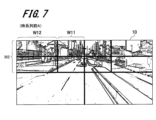
- FIG. 3 is a diagram illustrating how a photographed image photographed before A in chronological order is divided according to an embodiment of the present invention.
- FIG. 7 is a diagram illustrating how a captured image captured after B in time series is divided according to an embodiment of the present invention.
- FIG. 3 is a diagram showing an example of feature points detected from a first captured image according to an embodiment of the present invention.
- FIG. 7 is a diagram showing an example of feature points detected from a second captured image according to an embodiment of the present invention.
- FIG. 2 is a diagram illustrating an example of a rectified image in which the distribution of feature points is biased, to which a conventional technique is applied. This is an example of a parallelized image in which the distribution of feature points is equalized by applying a technique according to an embodiment of the present invention.
- FIG. 1 is a block diagram showing an example of the hardware configuration of a computer according to an embodiment of the present invention.
- the present invention is applicable to, for example, an arithmetic unit for vehicle control that can communicate with an in-vehicle ECU (Electronic Control Unit) for advanced driver assistance systems (ADAS) or autonomous driving (AD). It is.
- ECU Electronic Control Unit
- ADAS advanced driver assistance systems
- AD autonomous driving
- FIG. 1 is a block diagram showing an example of the internal configuration of an image processing apparatus 100 according to an embodiment.
- the image processing device 100 is one of the devices installed in an image processing ECU (not shown) installed in a vehicle. Furthermore, the image processing device 100 has a highly accurate calibration function.
- the vehicle-mounted camera 101 is an example of a camera mounted on a vehicle for the image processing device 100 to recognize the outside world of the vehicle, and photographs the outside world at a predetermined timing.
- the vehicle-mounted camera 101 outputs a captured image 10 of the surroundings of the vehicle to the equalization feature point detection unit 102 of the image processing device 100 in order to recognize the three-dimensional distance in the outside world.
- the in-vehicle camera 101 may be two stereo cameras or one monocular camera.
- the captured image 10 outputted by the on-vehicle camera 101 to the equalized feature point detection unit 102 may be two captured images 10 captured simultaneously by two cameras (stereo cameras), or may be two captured images 10 captured simultaneously by two cameras (stereo cameras), or two captured images 10 captured by one camera (monocular camera). Two photographed images 10 taken at different times may be used.
- a monocular camera is used as the in-vehicle camera 101, for example, one shot image 10 of an object taken by the monocular camera while the vehicle is stationary, and one shot image 10 of the same object taken after the vehicle has moved a little.
- the photographed image 10 is output.
- the image processing device 100 calibrates the relative parameters of the in-vehicle camera 101 based on the two captured images 10 and performs processing to recognize the three-dimensional distance of the outside world from the captured images 10.
- the calibration by the image processing device 100 is executed every time the in-vehicle camera 101 is activated. For example, the calibration is performed immediately after the vehicle is powered on and the in-vehicle camera 101 is activated, or at predetermined time intervals while the vehicle is running.
- the image processing device 100 includes an equalized feature point detection section 102, a feature point matching section 103, a relative parameter calculation section 104, a parallax image generation section 105, and a three-dimensional distance recognition section 106. The processing of each functional unit will be described below with reference to FIG.
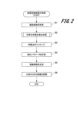
- FIG. 2 is a flowchart showing an example of the overall processing of the image processing device 100.
- FIG. 2 shows an example of an image processing method of the image processing apparatus 100.
- the equalized feature point detection unit 102 acquires the photographed image 10 from the vehicle-mounted camera 101 (S1).
- the received captured image 10 is stored in a storage device such as a RAM 53 and a non-volatile storage 55 shown in FIG. .
- a storage device such as a RAM 53 and a non-volatile storage 55 shown in FIG. .
- description of the process of inputting and outputting the captured image 10 to and from the storage device will be omitted.
- step S1 the equalization feature point detection unit 102 analyzes the captured image 10 received from the on-vehicle camera 101, and analyzes the contours of objects (roadways, sidewalks, other vehicles, signs, etc.) that appear in the captured image 10. Detect lines. Thereafter, the equalized feature point detection unit 102 performs the equalized feature point detection process shown in FIG. Detected as.
- the equalized minutiae detection unit 102 applies a unique method in the equalization minutiae detection processing shown in step S2, and can detect a minutiae that increases the accuracy of the relative parameters later calculated by the relative parameter calculation unit 104. Add operations like this.
- the operations performed by the equalized feature point detection unit 102 include dividing the captured image 10, detecting feature points in the regions divided by the dividing process, counting the number of feature points, and setting thresholds (individual thresholds) used for detecting feature points. Includes processing. By operating the equalized feature point detection unit 102, feature points are detected so that the number of feature points in each divided area into which the captured image 10 is divided by the division process is equalized.
- the equalized feature point detection section 102 includes a region division section 1021, a feature point detection section 1022, and a threshold value setting section 1023.
- the area dividing unit (area dividing unit 1021) divides each of the plurality of photographed images 10 taken by the vehicle-mounted camera (vehicle-mounted camera 101) into a plurality of divided regions.
- a feature point detection unit (feature point detection unit 1022) detects a portion exceeding a threshold (individual threshold) for each divided region as a feature point.
- the threshold setting unit (threshold setting unit 1023) sets a threshold (individual threshold) for each divided area so that the distribution of feature points detected for each divided area is even.
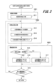
- FIG. 3 is a flowchart illustrating an example of the equalized feature point detection process performed by the equalized feature point detection unit 102.
- the equalized feature point detection process is part of an image processing method performed by each functional unit of the image processing apparatus 100 shown in FIG.
- the area dividing unit 1021 divides the photographed image 10 received from the in-vehicle camera 101 into a predetermined size and division number (S11).
- a predetermined size and division number S11
- an example of processing performed by the area dividing unit 1021 and an example of divided areas will be described with reference to FIGS. 4 to 8.
- the area dividing unit 1021 captures each of the two captured images 10 obtained from the in-vehicle camera 101, one by one.
- the area dividing unit (area dividing unit 1021) divides the captured image 10 by increasing the number of divisions and decreasing the size of the divided areas so that at least one feature point is detected in each divided area. Examples of dividing the captured image 10 are shown in FIGS. 4 and 5, for example.
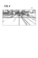
- FIG. 4 is a diagram showing an example of a video (captured image 10) divided into uniform grid shapes.
- a photographed image 10 taken by the in-vehicle camera 101 shown in FIG. 4 is divided by an area dividing unit 1021 into four equal grid-like divided areas of 2 rows by 2 columns. In this case, the number of divisions of the captured image 10 is "4". Further, the size of each divided area is the same. By dividing the photographed image 10 into four, the size of the divided area becomes one-fourth the size of the original photographed image 10. Even when the photographed image 10 is divided into four parts in this manner, it can be expected that the feature points in the photographed image 10 will be evenly arranged in each divided area depending on the object.
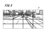
- FIG. 5 is a diagram illustrating an example of a video divided into grid shapes by increasing the number of divisions.
- a photographed image 10 photographed by the in-vehicle camera 101 shown in FIG. 5 is divided into 16 equal grid-like divided regions arranged in 4 rows and 4 columns by the region dividing unit 1021.
- the number of divisions of the captured image 10 is "16".
- the size of each divided area is the same.
- the size of the divided area shown in FIG. 5 becomes one-fourth the size of the divided area shown in FIG. 4.
- the area dividing unit 1021 can evenly arrange the feature points included in the photographed image 10 in each divided area.
- the area dividing unit 1021 increases the number of divisions of the photographed image 10 and divides the photographed image 10 into divided regions of small size.
- feature points are evenly distributed in each divided area. For example, if 100 feature points are randomly arranged throughout the photographed image 10, the arrangement positions of the feature points will be biased. This means that after randomly arranging 100 feature points throughout the photographed image 10, if the entire photographed image 10 is divided into 100 equal parts, the divided regions containing one or more feature points and the feature points will be divided into 100 equal parts. This is because it is expected that some divided areas will not be included.
- the image processing device 100 can perform calibration using the feature points detected in the entire captured image 10. It becomes possible.
- FIG. 6 is a diagram showing an example of a captured image 10 divided according to the vehicle situation.
- the in-vehicle camera 101 is installed in a vehicle, there is a high possibility that relatively close objects will appear large in the lower part of the captured image 10, and objects that are far away will likely appear smaller in the upper part of the captured image 10. Highly sexual.
- the lower side of the photographed image 10 has a large area where the roadway with a flat density is reflected.
- the area dividing unit changes the position and size of the area into which the captured image 10 is divided, depending on the mounting position of the vehicle-mounted camera (vehicle-mounted camera 101). For example, the area dividing unit 1021 divides the photographed image 10 into a small number of divisions and a large divided area in a region where a nearby object appears large, taking into consideration the vehicle situation and the characteristics of the photographed image 10. . On the other hand, for a portion where a small object appears at a long distance, the number of divisions is increased, and the photographed image 10 is divided into smaller divided areas.
- a long-distance portion (the upper half of the captured image 10) that corresponds to the traveling direction of the vehicle is detected by the three-dimensional distance recognition unit 106 (see FIG. 1). It is necessary to recognize the distance from the object to the object in detail.
- the area dividing unit 1021 of the equalized feature point detection unit 102 calculates what size objects appear in which areas on average, and the feature points in those areas.
- the division pattern of the photographed image 10 (the number of divided regions and the division size of each divided region) is determined in consideration of the driving scene, such as in which direction and how much the vehicle moves over time.
- the area dividing unit divides the captured image 10 of the portion predicted to have many feature points into smaller sizes than the portion predicted to have fewer feature points. For example, in FIG. 6, the part near the middle of the long-distance part (the part where the road is reflected) is divided into small sizes, and the vicinity of both ends of the long-distance part (the part where the sidewalk is shown) is divided into large sizes.
- the area dividing unit 1021 divides the area expected to have many feature points (long distance road, sidewalk, etc.) from the area expected to have few feature points (short distance road, sidewalk, etc.).
- the photographed image 10 can be divided into larger sizes.
- the area dividing unit 1021 changes the number of divisions and the division size according to the characteristics of the object shown in the photographed image 10, thereby dividing the number of feature points detected from the divided area showing the object at a close distance and the object at a long distance.
- the number of feature points detected from the divided regions in which objects are reflected can be made to be nearly equal. As a result, it is possible to improve the calibration accuracy of the captured image 10 in the depth direction by the image processing device 100.
- FIGS. 7 and 8 are diagrams showing examples of photographed images 10 taken by the vehicle-mounted camera 101 at different times.
- FIG. 7 is a diagram showing how the photographed image 10 photographed before the time series A is divided.
- FIG. 8 is a diagram showing how the photographed image 10 photographed after time series B is divided.
- the photographed image 10 shown in FIG. 8 is taken a time t after the photographed image 10 taken in FIG. 7 .
- the captured image 10 shown in FIG. 8 is an image captured by the on-vehicle camera 101 while the vehicle has moved forward for the time t.
- the area dividing unit calculates prediction results of feature points corresponding to three-dimensional positions in the outside world detected from a plurality of captured images 10 taken by an on-vehicle camera (on-vehicle camera 101) as the vehicle moves. Based on this, the plurality of captured images 10 are divided into different sizes. For example, the area dividing unit 1021 determines where the feature points corresponding to the three-dimensional positions detected from each of the photographed image 10 taken before the time series A and the photographed image 10 taken after the time series B are located. Predict what will happen. Then, the area dividing unit 1021 divides the two captured images 10 into different division sizes so that the predicted feature point positions are included.
- the height H1 of the upper area divided into eight divided areas in the image shown in FIG. , and the upper area of the photographed image 10 is wider.
- the left side area of the image shown in FIG. 7 is divided by a width W11 including a roadway located at a long distance, and a width W12 of an area including a sidewalk located at a long distance.
- the vehicle is moving forward and approaching the object. Therefore, the area on the left side of the image shown in FIG. 8 is wider than the width W11 shown in FIG. 7, as shown by the width W21 including the roadway located at a long distance.
- the width W22 of the left side region of the image shown in FIG. 8, including the sidewalk located far away is narrower than the width W12 shown in FIG.
- the feature point detection unit 1022 detects the characteristics of the area (for example, a road) where there is an object of interest in the direction of travel of the vehicle. Points can be detected reliably. Further, when the feature point matching unit 103, which will be described later, matches divided regions, it is possible to reduce malfunctions such as matching incorrect divided regions.
- the feature point detection unit 1022 selects one divided area divided by the area dividing unit 1021 (S12). Then, the feature point detection unit 1022 detects feature points of the divided regions using the individual thresholds for the divided regions selected in step S12 (S13).
- a detection threshold is used to increase or decrease the number of feature points that the feature point detection unit 1022 detects in the divided regions. Normally, one value is set for each feature point detection threshold for each photographed image 10. On the other hand, the feature point detection unit 1022 according to the present embodiment can individually set the detection threshold for each divided region. Therefore, the detection threshold set for each divided area is called an "individual threshold.” The individual threshold is a value set for each divided area by a threshold setting unit 1023, which will be described later.
- the individual threshold values set by the threshold setting unit 1023 have a range of values that can be set.
- a brightness threshold is used as the individual threshold.
- the feature point detection unit 1022 counts the number of feature points of the divided regions detected in step S13 (S14).
- the number of feature points of the divided regions counted by the feature point detection unit 1022 is temporarily stored in the RAM 53 (see FIG. 13) or the like.
- the threshold value setting unit 1023 sets a threshold value in order to equalize the feature points detected by the feature point detection unit 1022. Therefore, the threshold value setting unit 1023 compares the number of feature points with a target value for each divided region in which the number of feature points was counted in step S14, and determines whether the number of feature points is greater than the target value (S15). In steps S15 to S17, the threshold setting unit (threshold setting unit 1023) performs settings to raise the threshold set in the divided regions where the number of feature points is greater than the target value, and when the number of feature points is less than the target value. Perform settings to lower the threshold set for the divided area. Therefore, the individual threshold value is set so that the number of feature points detected by the feature point detection unit 1022 is close to the target value.
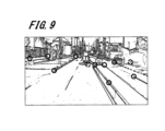
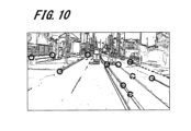
- the number of feature points will be explained with reference to FIGS. 9 and 10.
- FIG. 9 is a diagram showing an example of feature points detected from the first photographed image 10.
- FIG. 10 is a diagram showing an example of feature points detected from the second photographed image 10.
- the solid line and broken line circles shown in FIGS. 9 and 10 represent feature points. However, the solid-line circles represent feature points that were detected and matched with feature points indicating the same region in the two captured images 10, and the broken-line circles represent feature points that were not detected in the same region in the two captured images 10. represents.
- feature point matching is performed by comparing the feature amount of one feature point in one captured image 10 (reference image) and the feature amount of all feature points in the other captured image 10 (reference image), and then This is done by searching for feature points with similar amounts.
- the feature amount is a numerical value indicating the shape of a feature point, and is obtained by converting the arrangement of pixels (luminance values) around the feature point into a numerical value using a fixed procedure.
- the feature points are assumed to have various shapes, but if they are the same object, it is expected that the feature points will be the same.
- the matching of feature points is performed for divided regions at the same position in the two captured images 10, the load is lighter than the processing of matching feature points detected in the entire captured image 10, and the matching The time required to complete the process can also be shortened.
- the threshold setting unit 1023 determines that the number of feature points in this divided area is greater than the target value. (NO in S15). Therefore, the threshold value setting unit 1023 performs processing to increase the individual threshold value (S16). As a result, the detection threshold in this divided area becomes the maximum value. In other words, it is the maximum detection threshold within the settable range. However, by dividing the current individual threshold value to the maximum value at predetermined intervals, the individual threshold values may be set at the divided intervals in step S16. Therefore, the individual threshold value may be set to a value smaller than the maximum value.
- the threshold setting unit 1023 determines that the number of feature points in this divided area is less than or equal to the target value. (NO in S15). Therefore, the threshold setting unit 1023 performs processing to lower the feature point detection threshold (S17). As a result, the detection threshold in this divided area becomes the minimum value. In other words, it is the minimum detection threshold within the settable range. However, by dividing the current individual threshold value to the minimum value at predetermined intervals, the individual threshold values may be set at the divided intervals in step S17. Therefore, the individual threshold value may be set to a value larger than the minimum value.
- the equalization feature point detection unit 102 determines whether the processing from step S12 onward has been performed on all divided regions divided by the region division unit 1021 (S18).
- the equalized feature point detection unit 102 performs the processing from step S12 again on the unprocessed divided regions.
- the feature point detection section detects feature points using the threshold set by the threshold setting section (threshold setting section 1023). Therefore, the number of feature points detected by the feature point detection unit 1022 matches the target value.
- the equalization feature point detection unit 102 determines that the processing has been performed on all divided regions (YES in S18)
- the equalization feature point detection process shown in FIG. 3 is ended.
- the feature point detection unit 1022 sets the individual threshold values for another divided region. Feature point detection processing is performed using the individual thresholds set in the previous processing. This process is performed in order to shorten the processing time for all divided regions when the equalized feature point detection process shown in FIG. 3 is implemented.
- the feature point detection unit 1022 may perform feature point detection again in the same divided area.
- the feature point detection unit 1022 again detects a feature point for the same divided area using the set individual threshold. Thereafter, the process from step S12 may be performed on another divided area without performing the individual threshold setting process by the threshold setting unit 1023.
- the feature point matching unit (feature point matching unit 103) associates feature points with each divided region having the same position in the plurality of photographed images 10. Perform matching. Therefore, compared to the conventional processing in which feature points are matched for the entire captured image 10, the feature point matching unit 103 matches feature points uniformly detected in the entire captured image 10. You can attach and match.
- the feature point matching process is as described above with reference to FIGS. 9 and 10.
- the feature point matching unit 103 utilizes the divided regions divided by the region dividing unit 1021, and for one feature point in the divided region in one captured image 10, the feature point matching unit 103 uses the divided regions divided by the region dividing unit 1021 to Change to compare feature points.
- the range of the divided regions to be matched is limited, so the feature point matching unit 103 can avoid erroneously matching feature points detected in other divided regions, and the matching operation can be performed easily.
- the time required can be shortened.
- the relative parameter calculation unit calculates relative parameters based on the feature points associated between the plurality of captured images 10 (S4). Therefore, the relative parameter calculation unit 104 calculates relative parameters using the camera parameters and the matched feature points.
- the relative parameter is a parameter that indicates the relationship between the relative position and orientation of one camera as seen from one camera before and after the two vehicle-mounted cameras 101 or one moving vehicle-mounted camera 101 moves. Then, when calculating the relative parameters, the relative parameter calculation unit 104 performs calculations so as to minimize the sum of reprojection errors of all matched feature points in the two captured images 10.
- the relative parameter calculation unit calculates that one of the two cameras forming the stereo camera captures the captured image 10.
- the axial position and axial angle of one camera at the time of photographing are taken as a reference, and the relative axial position and axial angle of the other camera when the other camera photographs the other photographed image 10 are used as relative parameters.
- the relative three-dimensional position ((x, y, z) axis position) and relative orientation ((x, y, z) axis angle of the left camera with respect to the reference) ) is a relative parameter.
- the vehicle-mounted camera 101 is a monocular camera
- the photographed images 10 taken before and after one moving vehicle-mounted camera 101 is moved are used.
- the posture of a single-purpose camera is difficult to remain constant before and after movement.
- the attitude of the vehicle-mounted camera 101 is constant.
- the angle of the in-vehicle camera 101 changes left and right due to minute steering wheel operations, and the angle of the in-vehicle camera 101 changes up and down when the brake or accelerator is applied, so the attitude of the in-vehicle camera 101 is assumed to change. be done.
- the relative parameter calculation unit calculates, among a plurality of captured images 10 taken by the monocular camera as the vehicle moves, The relative axial position and axial angle of the monocular camera when one captured image 10 was captured is taken as a reference, and the relative axial position and axial angle of the monocular camera when the other captured image 10 was captured is used as a relative parameter.
- the relative three-dimensional position ((x, y, z) axis position) and relative orientation (( x, y, z) axis angles) are relative parameters.
- the relative parameters are calculated correctly.
- the parallax image generation unit (parallax image generation unit 105) generates parallax images of the plurality of captured images 10 based on the relative parameters (S5). Therefore, the parallax image generation unit 105 creates a parallelized image by parallelizing the two captured images 10 based on the relative parameters. In the parallelized image, the epipolar line is horizontal and has the same Y coordinate. Then, the parallax image generation unit 105 performs stereo matching on the parallelized video to generate a parallax image.
- the three-dimensional distance recognition unit (three-dimensional distance recognition unit 106) recognizes the three-dimensional distance in the outside world based on the parallax image (S6).
- the three-dimensional distance recognition unit 106 uses the parallax value of the parallax image generated by the parallax image generation unit 105, the focal length of the camera included in the camera parameters, the pixel size of the light receiving element configured in the vehicle camera 101, etc. Based on this, the three-dimensional distance to the outside world is calculated and objects in the outside world are recognized. After that, the processing of the image processing device 100 ends.
- the three-dimensional distance recognition unit 106 can calculate the three-dimensional distance in the outside world and recognize objects in the outside world. It is. In this case, the vehicle-mounted camera 101 photographs the outside world at timings before and after the vehicle moves in chronological order, and it is known exactly how the vehicle-mounted camera 101 moves between the two captured images 10. This is necessary. Note that if the vehicle-mounted camera 101 is composed of two stereo cameras, the camera positions of the two images 10 taken by the stereo cameras are fixed and can be accurately known.
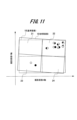
- FIG. 11 is a diagram showing an example of a rectified image in which the distribution of feature points is biased, to which the conventional technique is applied.
- the horizontal axis in FIG. 11 takes the X axis of the photographed image 10, and the vertical axis takes the Y axis of the photographed image 10.
- the black circles and dashed ruled lines shown in the figure indicate feature points detected from the captured image 10 (reference image) captured by one camera and the inclination of the parallelized image. Furthermore, white circles and solid ruled lines shown in the figure indicate the feature points detected from the captured image 10 (reference image) captured by the other camera and the inclination of the parallelized image. Ideally, it is expected that the two parallelized images will have the same inclination.
- the two photographed images 10 are divided into regions 21 to 24 of 2 rows and 2 columns.
- weights are calculated for the feature points.
- the weight is a value that is added to the error of the feature point detected from the two-dimensional photographed image 10 (the error between white circles and black circles shown in the figure).
- the errors of many feature points are accumulated, so the weight for the evaluation value of the feature point becomes large.
- the errors of a small number of feature points are only accumulated, so even if the error of one feature point is large, the weight on the evaluation value of the feature point becomes small.
- the weight in the relative parameter calculation of the region 22 shown in FIG. 11 where the feature points are dense is increased, and the weight of the region 23 where the feature points are sparse is decreased. Therefore, in the relative parameter calculation, a relative parameter that has a large weight and is optimized for an area where feature points are densely packed is calculated, and a large deviation occurs in the area 23 where feature points are sparse.
- the captured image 10 (reference image) indicated by the solid line is tilted significantly and is not parallelized compared to the captured image 10 (reference image) indicated by the broken line.
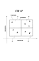
- FIG. 12 is an example of a parallelized image in which the distribution of feature points is equalized by applying the technique according to the present embodiment.
- the black circles, white circles, broken lines, and solid ruled lines shown in the figure are the same as those shown in FIG. 11.
- feature points are evenly distributed in regions 21 to 24 (the entire image) of the two captured images 10. Therefore, the weights in the calculation of relative parameters are also equalized within the two captured images 10. As a result, calculation results with less distortion can be obtained.
- the captured image 10 (reference image) indicated by the broken line the captured image 10 (reference image) indicated by the solid line has a suppressed inclination and is parallelized.
- FIG. 13 is a block diagram showing an example of the hardware configuration of the computer 50.
- the computer 50 is an example of hardware used as a computer that can operate as the image processing apparatus 100 according to the present embodiment.
- the image processing apparatus 100 according to the present embodiment realizes an image processing method performed by the functional blocks shown in FIGS. 1 and 3 in cooperation with each other by the computer 50 (computer) executing a program.
- the computer 50 includes a CPU (Central Processing Unit) 51, a ROM (Read Only Memory) 52, and a RAM (Random Access Memory) 53, each connected to a bus 54. Furthermore, the computer 50 includes a nonvolatile storage 55 and a network interface 56.
- a CPU Central Processing Unit
- ROM Read Only Memory
- RAM Random Access Memory
- the CPU 51 reads out software program codes that implement each function according to the present embodiment from the ROM 52, loads them into the RAM 53, and executes them. Variables, parameters, etc. generated during the calculation process of the CPU 51 are temporarily written in the RAM 53, and these variables, parameters, etc. are read out by the CPU 51 as appropriate.
- an MPU Micro Processing Unit
- non-volatile storage 55 for example, an HDD (Hard Disk Drive), SSD (Solid State Drive), flexible disk, optical disk, magneto-optical disk, CD-ROM, CD-R, magnetic tape, or non-volatile memory is used. It will be done.
- This nonvolatile storage 55 stores an OS (Operating System), various parameters, and programs for making the computer 50 function.
- the ROM 52 and the non-volatile storage 55 record programs, data, etc. necessary for the operation of the CPU 51, and serve as an example of a computer-readable non-transitory storage medium that stores programs to be executed by the computer 50. used.
- a NIC Network Interface Card
- LAN Local Area Network
- the three-dimensional distance recognition unit 106 included in the image processing device 100 can recognize a three-dimensional position represented by a three-dimensional distance in the outside world more accurately than before.
- the two captured images 10 used for matching are divided by the area division unit 1021 into the same size and division number.
- the captured image 10 is divided such that at least one feature point is detected in each divided region. Therefore, the feature points are evenly arranged in each divided region, so that the feature points are evenly arranged in the entire captured image 10. Furthermore, it becomes easier to match feature points for each divided region at the same position in each photographed image 10.
- the size of the divided regions is changed according to the predicted number of feature points for each portion of the photographed image 10.
- the photographed image 10 is divided so that the size of a portion predicted to have a large number of feature points is small, and the size of a portion predicted to have a small number of feature points is large. As a result, even in a portion where the number of feature points is predicted to be small, at least one feature point is detected.
- the individual threshold values for detecting feature points can be changed for each divided region. Therefore, by setting a high individual threshold for a portion predicted to have a large number of feature points, it is possible to reduce the number of detected feature points. Conversely, the number of detected feature points can be increased by setting a low individual threshold for a portion predicted to have a small number of feature points. As a result, the number of feature points detected for each divided region is equalized.
- the image processing apparatus 100 has more opportunities to perform calibration, and can perform calibration more frequently and accurately than before.
- the equalized feature point detection unit 102 sets the individual threshold after detecting feature points from the divided regions into which the two captured images 10 acquired at the first timing are divided. Then, the equalized feature point detection unit 102 detects feature points in the divided regions into which the two captured images 10 obtained at the next timing are divided, using the individual threshold set at the first timing.
- the 3D distance recognition unit 106 calculates the 3D distance in the outside world by using the individual threshold set first for the captured image 10 captured twice in a short period of time to detect feature points. You will be able to recognize it more accurately.
- DESCRIPTION OF SYMBOLS 10 Photographed image, 100... Image processing device, 101... Vehicle-mounted camera, 102... Equalization feature point detection unit, 103... Feature point matching unit, 104... Relative parameter calculation unit, 105... Parallax image generation unit, 106... Three-dimensional Distance recognition section, 1021... Area division section, 1022... Feature point detection section, 1023... Threshold value setting section
Landscapes
- Engineering & Computer Science (AREA)
- Physics & Mathematics (AREA)
- General Physics & Mathematics (AREA)
- Theoretical Computer Science (AREA)
- Computer Vision & Pattern Recognition (AREA)
- Multimedia (AREA)
- Software Systems (AREA)
- Image Analysis (AREA)
- Image Processing (AREA)
Abstract
Description
図1は、一実施形態に係る画像処理装置100の内部構成例を示すブロック図である。
画像処理装置100は、車両に搭載される不図示の画像処理ECUに搭載される装置の一つである。また、画像処理装置100は、高精度な校正機能を有する
領域分割部(領域分割部1021)は、車載カメラ(車載カメラ101)が撮影した複数の撮影画像10をそれぞれ複数の分割領域に分割する。
特徴点検出部(特徴点検出部1022)は、分割領域ごとに閾値(個別閾値)を超える部分を特徴点として検出する。
閾値設定部(閾値設定部1023)は、分割領域ごとに検出される特徴点の分布が均等になるように分割領域ごとに閾値(個別閾値)を設定する。
以下に、均等化特徴点検出部102が有する各機能部により行われる均等化特徴点検出処理について、図3以降を参照して後述する。
図4に示す車載カメラ101が撮影した撮影画像10は、領域分割部1021により、2行×2列の4個の均等なグリッド状の分割領域に分割される。この場合、撮影画像10の分割数は「4」である。また、各分割領域のサイズは、いずれも同じである。撮影画像10を4つに分割することで、分割領域のサイズは、元の撮影画像10の4分の1のサイズとなる。このように撮影画像10を4分割する場合であっても、対象物によっては撮影画像10内の特徴点を各分割領域に均等に配置することが期待できる。
図5に示す車載カメラ101が撮影した撮影画像10は、領域分割部1021により、4行×4列の16個の均等なグリッド状の分割領域に分割される。この場合、撮影画像10の分割数は「16」である。また、各分割領域の大きさは、いずれも同じである。そして、分割数を増やしたことで、図5に示す分割領域のサイズは、図4に示した分割領域の4分の1のサイズとなる。領域分割部1021は、分割数を増やすことで、撮影画像10内に含まれる特徴点を各分割領域に均等に配置することができる。
車載カメラ101が車両に搭載されることを考慮すると、撮影画像10の下側は、比較的近距離の物体が大きく映る可能性が高く、撮影画像10の上側は遠距離のものが小さく映る可能性が高い。また、車両の前方に他の車両が走行していない場合、撮影画像10の下側は、濃度が平坦な車道が映る範囲が大きい。
図7と図8は、異なる時間で車載カメラ101が撮影した撮影画像10の例を示す図である。
図7は、時系列前Aに撮影された撮影画像10を分割した様子を示す図である。
図8は、時系列後Bに撮影された撮影画像10を分割した様子を示す図である。図8に示される撮影画像10は、図7で撮影された撮影画像10に対して、時間tだけ後に撮影されたものである。つまり、図8に示される撮影画像10は、時間tの分だけ、車両が前進した状態で車載カメラ101が撮影した映像である。
ステップS11の処理の後、特徴点検出部1022は、領域分割部1021によって分割された分割領域を1つ選択する(S12)。そして、特徴点検出部1022は、ステップS12で選択した分割領域に対して個別閾値を用いて、分割領域の特徴点検出を行う(S13)。
図10は、2つ目の撮影画像10から検出された特徴点の例を示す図である。
図9と図10に示す実線及び破線の円が特徴点を表す。ただし、実線の円は2枚の撮影画像10で同じ部位を示す特徴点が検出されマッチングされた特徴点を表し、破線の円は2枚の撮影画像10から同じ部位で検出されなかった特徴点を表す。
図9に示す撮影画像10の左上側(奥側)が、図6に示した分割パターンで分割された分割領域であるとする。この場合、撮影画像10の左上側(奥側)の分割領域には、多くの特徴点が検出されているので、閾値設定部1023は、この分割領域における特徴点数が目標値より多いと判定する(S15のNO)。そこで、閾値設定部1023は、個別閾値を上げる処理を行う(S16)。この結果、この分割領域での検出閾値は最大値となる。つまり、設定可能範囲内で最大の検出閾値となる。ただし、現在の個別閾値から最大値までが所定間隔で区分されることで、ステップS16では区分された間隔で個別閾値が設定されてもよい。このため、個別閾値が最大値よりも小さい値に設定されてもよい。
図3に示した均等化特徴点検出部102の処理の後、特徴点マッチング部(特徴点マッチング部103)は、複数の撮影画像10で検出された特徴点を複数の撮影画像10の間で対応付けてマッチングを行う(S3)。この時、特徴点マッチング部103は、均等化特徴点検出部102から出力された2つの撮影画像10内で同じ部位として検出された特徴点を対応付けるマッチングを行う。このため、特徴点マッチング部103は、従来のように分割前の2つの撮影画像10で検出された特徴点をマッチングすることができる。
図12においても、図中に示す黒丸、白丸、破線及び実線の罫線は、図11に示したものと同様である。
図12に示す平行化映像の例では、2つの撮影画像10の領域21~24(画像全体)に特徴点が均等に分布している。このため、相対パラメータの計算における重みも2つの撮影画像10内で均等化される。この結果、歪みの少ない計算結果を得ることができる。また、破線で示す撮影画像10(基準画像)に対して、実線で示す撮影画像10(参照画像)は、傾きが抑えられており、平行化されている。
図13は、計算機50のハードウェア構成例を示すブロック図である。計算機50は、本実施の形態に係る画像処理装置100として動作可能なコンピューターとして用いられるハードウェアの一例である。本実施の形態に係る画像処理装置100は、計算機50(コンピューター)がプログラムを実行することにより、図1及び図3に示した各機能ブロックが連携して行う画像処理方法を実現する。
なお、ステレオカメラに構成される一方のカメラに故障が発生した場合であれば、他方のカメラ(例えば、右側のカメラ)だけを使って、車両の移動前後で撮影された撮影画像10を用いて校正を行ってもよい。この場合、車載カメラ101に単眼カメラを用いた場合と同様の処理で、片側のカメラを校正することができる。
例えば、上述した実施形態は本発明を分かりやすく説明するためにシステムの構成を詳細かつ具体的に説明したものであり、必ずしも説明した全ての構成を備えるものに限定されない。また、本実施形態の構成の一部について、他の構成の追加、削除、置換をすることも可能である。
また、制御線や情報線は説明上必要と考えられるものを示しており、製品上必ずしも全ての制御線や情報線を示しているとは限らない。実際には殆ど全ての構成が相互に接続されていると考えてもよい。
Claims (11)
- 車載カメラが撮影した複数の撮影画像をそれぞれ複数の分割領域に分割する領域分割部と、
前記分割領域ごとに閾値を超える部分を特徴点として検出する特徴点検出部と、
前記分割領域ごとに検出される前記特徴点の分布が均等になるように前記分割領域ごとに前記閾値を設定する閾値設定部と、
複数の前記撮影画像で検出された前記特徴点を複数の前記撮影画像の間で対応付けてマッチングを行う特徴点マッチング部と、
複数の前記撮影画像の間で対応付けられた前記特徴点に基づいて、相対パラメータを計算する相対パラメータ計算部と、を備える
画像処理装置。 - 前記閾値設定部は、前記特徴点の数が目標値よりも多い前記分割領域に設定される前記閾値を上げる設定を行い、前記特徴点の数が目標値未満である前記分割領域に設定される前記閾値を下げる設定を行い
前記特徴点検出部は、前記閾値設定部により設定された前記閾値で前記特徴点を検出する
請求項1に記載の画像処理装置。 - 前記領域分割部は、前記分割領域ごとに少なくとも一つの前記特徴点が検出されるように、前記撮影画像の分割数を増やし、前記分割領域のサイズを小さくして分割する
請求項2に記載の画像処理装置。 - 前記領域分割部は、前記車載カメラの搭載位置に応じて、前記撮影画像を分割する領域の位置及び大きさを変更する
請求項3に記載の画像処理装置。 - 前記領域分割部は、前記特徴点が多いと予測される部分の前記撮影画像を、前記特徴点が少ないと予測される部分よりも小さいサイズで分割する
請求項4に記載の画像処理装置。 - 前記領域分割部は、車両の移動に伴って前記車載カメラにより撮影される複数の前記撮影画像から検出される外界の3次元位置に対応する特徴点の予測結果に基づいて、複数の前記撮影画像をそれぞれ異なるサイズで分割する
請求項4に記載の画像処理装置。 - 前記特徴点マッチング部は、複数の前記撮影画像における位置が同じ前記分割領域ごとに前記特徴点を対応付けてマッチングを行う
請求項5に記載の画像処理装置。 - 前記相対パラメータ計算部は、前記車載カメラがステレオカメラである場合に、前記ステレオカメラを構成する2つのカメラのうち、一方のカメラが前記撮影画像を撮影した時の前記一方のカメラの軸位置及び軸角度を基準とし、他方のカメラが他の前記撮影画像を撮影した時の前記他方のカメラの相対的な軸位置及び軸角度を前記相対パラメータとする
請求項6に記載の画像処理装置。 - 前記相対パラメータ計算部は、前記車載カメラが単眼カメラである場合に、車両の移動に伴って前記単眼カメラが撮影した複数の前記撮影画像のうち、一の前記撮影画像を撮影した時の前記単眼カメラの軸位置及び軸角度を基準とし、他の前記撮影画像を撮影した時の前記単眼カメラの相対的な軸位置及び軸角度を前記相対パラメータとする
請求項6に記載の画像処理装置。 - さらに、前記相対パラメータに基づいて複数の前記撮影画像の視差画像を生成する視差画像生成部と、
前記視差画像に基づいて、外界の3次元距離を認識する3次元距離認識部とを備える
請求項8に記載の画像処理装置。 - 車載カメラが撮影した複数の撮影画像をそれぞれ複数の分割領域に分割する処理と、
前記分割領域ごとに閾値を超える部分を特徴点として検出する処理と、
前記分割領域ごとに検出される前記特徴点の分布が均等になるように前記分割領域ごとに前記閾値を設定する処理と、
複数の前記撮影画像で検出された前記特徴点を、複数の前記撮影画像の間で対応付ける処理と、
複数の前記撮影画像の間で対応付けられた前記特徴点に基づいて、相対パラメータを計算する処理と、を含む
画像処理方法。
Priority Applications (5)
| Application Number | Priority Date | Filing Date | Title |
|---|---|---|---|
| DE112022007155.9T DE112022007155T5 (de) | 2022-07-05 | 2022-07-05 | Bildverarbeitungsvorrichtung und Bildverarbeitungsverfahren |
| PCT/JP2022/026698 WO2024009386A1 (ja) | 2022-07-05 | 2022-07-05 | 画像処理装置及び画像処理方法 |
| CN202280097237.9A CN119404075A (zh) | 2022-07-05 | 2022-07-05 | 图像处理装置及图像处理方法 |
| JP2024531786A JP7780648B2 (ja) | 2022-07-05 | 2022-07-05 | 画像処理装置及び画像処理方法 |
| US18/876,986 US12530801B2 (en) | 2022-07-05 | 2022-07-05 | Image processing device and image processing method |
Applications Claiming Priority (1)
| Application Number | Priority Date | Filing Date | Title |
|---|---|---|---|
| PCT/JP2022/026698 WO2024009386A1 (ja) | 2022-07-05 | 2022-07-05 | 画像処理装置及び画像処理方法 |
Publications (1)
| Publication Number | Publication Date |
|---|---|
| WO2024009386A1 true WO2024009386A1 (ja) | 2024-01-11 |
Family
ID=89452964
Family Applications (1)
| Application Number | Title | Priority Date | Filing Date |
|---|---|---|---|
| PCT/JP2022/026698 Ceased WO2024009386A1 (ja) | 2022-07-05 | 2022-07-05 | 画像処理装置及び画像処理方法 |
Country Status (5)
| Country | Link |
|---|---|
| US (1) | US12530801B2 (ja) |
| JP (1) | JP7780648B2 (ja) |
| CN (1) | CN119404075A (ja) |
| DE (1) | DE112022007155T5 (ja) |
| WO (1) | WO2024009386A1 (ja) |
Families Citing this family (1)
| Publication number | Priority date | Publication date | Assignee | Title |
|---|---|---|---|---|
| JP7726965B2 (ja) * | 2023-10-26 | 2025-08-20 | パナソニックオートモーティブシステムズ株式会社 | 駐車支援装置および駐車支援方法 |
Citations (3)
| Publication number | Priority date | Publication date | Assignee | Title |
|---|---|---|---|---|
| JP2009276233A (ja) * | 2008-05-15 | 2009-11-26 | Toyota Central R&D Labs Inc | パラメータ計算装置、パラメータ計算システムおよびプログラム |
| JP2020012735A (ja) * | 2018-07-18 | 2020-01-23 | 日立オートモティブシステムズ株式会社 | 車載環境認識装置 |
| JP2020134242A (ja) * | 2019-02-15 | 2020-08-31 | オリンパス株式会社 | 計測方法、計測装置、およびプログラム |
Family Cites Families (9)
| Publication number | Priority date | Publication date | Assignee | Title |
|---|---|---|---|---|
| US9070042B2 (en) | 2011-01-13 | 2015-06-30 | Panasonic Intellectual Property Management Co., Ltd. | Image processing apparatus, image processing method, and program thereof |
| JP2012234258A (ja) * | 2011-04-28 | 2012-11-29 | Sony Corp | 画像処理装置と画像処理方法およびプログラム |
| JP5768684B2 (ja) * | 2011-11-29 | 2015-08-26 | 富士通株式会社 | ステレオ画像生成装置、ステレオ画像生成方法及びステレオ画像生成用コンピュータプログラム |
| JP2013123123A (ja) * | 2011-12-09 | 2013-06-20 | Fujitsu Ltd | ステレオ画像生成装置、ステレオ画像生成方法及びステレオ画像生成用コンピュータプログラム |
| JP5832341B2 (ja) * | 2012-03-09 | 2015-12-16 | 株式会社トプコン | 動画処理装置、動画処理方法および動画処理用のプログラム |
| US10621433B1 (en) * | 2015-12-18 | 2020-04-14 | EControls Holdings, KKC | Multiscopic whitetail scoring game camera systems and methods |
| AU2018278901B2 (en) * | 2018-06-14 | 2020-07-16 | Beijing Didi Infinity Technology And Development Co., Ltd. | Systems and methods for updating a high-resolution map based on binocular images |
| JP7076357B2 (ja) * | 2018-10-30 | 2022-05-27 | 本田技研工業株式会社 | 感情推定装置 |
| SG11201811601SA (en) * | 2018-11-13 | 2020-06-29 | Beijing Didi Infinity Technology & Development Co Ltd | Methods and systems for color point cloud generation |
-
2022
- 2022-07-05 DE DE112022007155.9T patent/DE112022007155T5/de active Pending
- 2022-07-05 WO PCT/JP2022/026698 patent/WO2024009386A1/ja not_active Ceased
- 2022-07-05 JP JP2024531786A patent/JP7780648B2/ja active Active
- 2022-07-05 CN CN202280097237.9A patent/CN119404075A/zh active Pending
- 2022-07-05 US US18/876,986 patent/US12530801B2/en active Active
Patent Citations (3)
| Publication number | Priority date | Publication date | Assignee | Title |
|---|---|---|---|---|
| JP2009276233A (ja) * | 2008-05-15 | 2009-11-26 | Toyota Central R&D Labs Inc | パラメータ計算装置、パラメータ計算システムおよびプログラム |
| JP2020012735A (ja) * | 2018-07-18 | 2020-01-23 | 日立オートモティブシステムズ株式会社 | 車載環境認識装置 |
| JP2020134242A (ja) * | 2019-02-15 | 2020-08-31 | オリンパス株式会社 | 計測方法、計測装置、およびプログラム |
Also Published As
| Publication number | Publication date |
|---|---|
| JPWO2024009386A1 (ja) | 2024-01-11 |
| US20250378583A1 (en) | 2025-12-11 |
| DE112022007155T5 (de) | 2025-03-06 |
| CN119404075A (zh) | 2025-02-07 |
| JP7780648B2 (ja) | 2025-12-04 |
| US12530801B2 (en) | 2026-01-20 |
Similar Documents
| Publication | Publication Date | Title |
|---|---|---|
| JP7830407B2 (ja) | 電子機器、移動体、撮像装置、および電子機器の制御方法、プログラム、記憶媒体 | |
| US10776946B2 (en) | Image processing device, object recognizing device, device control system, moving object, image processing method, and computer-readable medium | |
| EP3082066B1 (en) | Road surface gradient detection device | |
| US20150367781A1 (en) | Lane boundary estimation device and lane boundary estimation method | |
| JP6733225B2 (ja) | 画像処理装置、撮像装置、移動体機器制御システム、画像処理方法、及びプログラム | |
| US10776649B2 (en) | Method and apparatus for monitoring region around vehicle | |
| KR102569437B1 (ko) | 3차원 영상정보 기반 객체 추적 장치 및 방법 | |
| CN112184827A (zh) | 校准多个摄像机的方法及装置 | |
| RU2621826C1 (ru) | Устройство вычисления собственного положения и способ вычисления собственного положения | |
| JP6457278B2 (ja) | 物体検出装置及び物体検出方法 | |
| CN107392080B (zh) | 影像评估方法以及其电子装置 | |
| JP6176387B2 (ja) | 自己位置算出装置及び自己位置算出方法 | |
| EP3115933B1 (en) | Image processing device, image capturing device, mobile body control system, image processing method, and computer-readable recording medium | |
| CN111989541B (zh) | 立体摄像机装置 | |
| JP2019530924A (ja) | カメラ画像からのオブジェクトの検出 | |
| CN105993042A (zh) | 自身位置计算装置以及自身位置计算方法 | |
| JP2020077293A (ja) | 区画線検出装置及び区画線検出方法 | |
| US20200193184A1 (en) | Image processing device and image processing method | |
| JP6577595B2 (ja) | 車両用外界認識装置 | |
| CN112758086B (zh) | 车外环境识别装置 | |
| JP6398218B2 (ja) | 自己位置算出装置及び自己位置算出方法 | |
| JP2010224936A (ja) | 物体検出装置 | |
| CN119365790A (zh) | 不同传感器模态例如摄像装置、雷达和激光雷达传感器的自动外部校准和校准验证 | |
| US12530801B2 (en) | Image processing device and image processing method | |
| JP2014130429A (ja) | 撮像装置及び立体物領域検出用プログラム |
Legal Events
| Date | Code | Title | Description |
|---|---|---|---|
| 121 | Ep: the epo has been informed by wipo that ep was designated in this application |
Ref document number: 22950180 Country of ref document: EP Kind code of ref document: A1 |
|
| WWE | Wipo information: entry into national phase |
Ref document number: 2024531786 Country of ref document: JP |
|
| WWE | Wipo information: entry into national phase |
Ref document number: 202280097237.9 Country of ref document: CN |
|
| WWE | Wipo information: entry into national phase |
Ref document number: 18876986 Country of ref document: US |
|
| WWE | Wipo information: entry into national phase |
Ref document number: 112022007155 Country of ref document: DE |
|
| WWP | Wipo information: published in national office |
Ref document number: 202280097237.9 Country of ref document: CN |
|
| WWP | Wipo information: published in national office |
Ref document number: 112022007155 Country of ref document: DE |
|
| 122 | Ep: pct application non-entry in european phase |
Ref document number: 22950180 Country of ref document: EP Kind code of ref document: A1 |
|
| WWP | Wipo information: published in national office |
Ref document number: 18876986 Country of ref document: US |
|
| WWG | Wipo information: grant in national office |
Ref document number: 18876986 Country of ref document: US |