WO2024005191A1 - 導光体 - Google Patents
導光体 Download PDFInfo
- Publication number
- WO2024005191A1 WO2024005191A1 PCT/JP2023/024402 JP2023024402W WO2024005191A1 WO 2024005191 A1 WO2024005191 A1 WO 2024005191A1 JP 2023024402 W JP2023024402 W JP 2023024402W WO 2024005191 A1 WO2024005191 A1 WO 2024005191A1
- Authority
- WO
- WIPO (PCT)
- Prior art keywords
- light
- light guide
- section
- continuous
- input
- Prior art date
- Legal status (The legal status is an assumption and is not a legal conclusion. Google has not performed a legal analysis and makes no representation as to the accuracy of the status listed.)
- Ceased
Links
Images


Classifications
-
- G—PHYSICS
- G02—OPTICS
- G02B—OPTICAL ELEMENTS, SYSTEMS OR APPARATUS
- G02B19/00—Condensers, e.g. light collectors or similar non-imaging optics
- G02B19/0033—Condensers, e.g. light collectors or similar non-imaging optics characterised by the use
- G02B19/0038—Condensers, e.g. light collectors or similar non-imaging optics characterised by the use for use with ambient light
- G02B19/0042—Condensers, e.g. light collectors or similar non-imaging optics characterised by the use for use with ambient light for use with direct solar radiation
-
- F—MECHANICAL ENGINEERING; LIGHTING; HEATING; WEAPONS; BLASTING
- F21—LIGHTING
- F21S—NON-PORTABLE LIGHTING DEVICES; SYSTEMS THEREOF; VEHICLE LIGHTING DEVICES SPECIALLY ADAPTED FOR VEHICLE EXTERIORS
- F21S11/00—Non-electric lighting devices or systems using daylight
-
- G—PHYSICS
- G02—OPTICS
- G02B—OPTICAL ELEMENTS, SYSTEMS OR APPARATUS
- G02B19/00—Condensers, e.g. light collectors or similar non-imaging optics
- G02B19/0004—Condensers, e.g. light collectors or similar non-imaging optics characterised by the optical means employed
- G02B19/0028—Condensers, e.g. light collectors or similar non-imaging optics characterised by the optical means employed refractive and reflective surfaces, e.g. non-imaging catadioptric systems
-
- G—PHYSICS
- G02—OPTICS
- G02B—OPTICAL ELEMENTS, SYSTEMS OR APPARATUS
- G02B5/00—Optical elements other than lenses
-
- G—PHYSICS
- G02—OPTICS
- G02B—OPTICAL ELEMENTS, SYSTEMS OR APPARATUS
- G02B6/00—Light guides; Structural details of arrangements comprising light guides and other optical elements, e.g. couplings
Definitions
- the present invention relates to a light guide.
- Patent Document 1 discloses a plurality of light guide parts each having a light guide part extending in parallel from an incident surface into which light enters, and a light converging part connected to the light guide part and gradually becoming thinner and having a reflective surface at the end.
- a lighting device includes a light condensing element, a plurality of coupling waveguides that guide light entering from the plurality of light condensing elements through reflective surfaces, and an integrated waveguide that connects to the plurality of coupling waveguides and collects the light. ing.
- the light collecting element in such a lighting device collects a lot of light, the light collecting efficiency is not necessarily high because the collected light leaks from the light collecting element when it travels backwards.
- the light guide may be a light guide that guides light input from a light input surface to a light output surface different from the light input surface and outputs the light from the light output surface.
- the light guide may include a light entrance portion having the light incident surface provided so that the light is input from a first direction.
- the light guide may include a light guide part that is disposed closer to the light exit surface than the light input part and that guides the light in a second direction intersecting the first direction and outputs it from the light exit surface. .
- the light guide is arranged at a boundary between the light input part and the light guide part, and includes a continuous part provided so that the light input part and the light guide part are continuous, and a continuous part provided between the light input part and the light guide part.
- a discontinuous portion may be provided so as to be separated from the light guide portion.
- a plurality of the continuous parts and a plurality of the discontinuous parts are provided at the boundaries of the light incident part and the light guide part, respectively, and the plurality of continuous parts and the plurality of discontinuous parts are arranged alternately along the second direction. may be placed in (Item 3)
- the continuous portion and the discontinuous portion may be arranged such that the length of the continuous portion is smaller than the length of the discontinuous portion in the second direction.
- the light input section may include a reflective surface provided to reflect the light input from the light input surface toward the continuous section.
- the reflective surface may be formed to reflect the light input from a direction perpendicular to the light input surface toward the continuous portion.
- the reflective surface may be curved or bent on a cross section including the first direction and the second direction.
- the light emitting device may further include another reflective surface that is disposed opposite to the reflective surface and reflects the light input from the light input surface toward the continuous portion.
- the light input portion may extend in the second direction.
- the light incident surface may be formed into a planar shape having a width in a third direction intersecting each of the first direction and the second direction.
- the light guide portion may be formed to extend in the second direction.
- the light guide portion In the first direction, the light guide portion may have a planar end portion opposite to the light input portion.
- the continuous portion may be formed to extend in the third direction.
- the continuous portion may be arranged such that the third direction is substantially parallel to a plane including a movement trajectory of the sun.
- the light incident part and the light guide part may be formed as separate bodies, and may be joined to each other via the continuous part.
- the light incident part and the light guide part may be joined by welding.
- the light incident part and the light guide part may be made of the same material.
- the discontinuous portion includes a first discontinuous portion in which the distance between the light input portion and the light guide portion is constant along the second direction, and a first discontinuity portion where the distance between the light input portion and the light guide portion is constant along the second direction; and a second discontinuous portion having an indefinite distance from the light portion.
- the light input section may include a reflective surface provided to reflect the light input from the light input surface toward the continuous section.
- the opposite surface of the reflective surface facing the light guide portion may be provided to constitute an end portion of the second discontinuous portion on the light input portion side.
- the light guide is disposed on the opposite side of the light input part with respect to the light guide part in the first direction, and is configured to receive the light that has passed through the light guide part. It may further include a light section.
- the light guide is arranged at another boundary between the light guide section and the light condensing section, and is connected to another continuous section and the guide provided so that the light guide section and the light condensing section are continuous.
- the light source may further include another discontinuous portion provided so that the light portion and the light condensing portion are spaced apart from each other.
- the light condensing section may include a light return section that returns light leaking from the light guide section to the light guide section.
- the light return section may have a reflective surface that reflects the leaked light toward the other continuous section.
- the light return section may have a refraction surface that refracts the leaked light reflected by the reflection surface toward the other continuous section.
- the reflective surface of the light return section may be arranged offset in the second direction with respect to the reflective surface of the light input section.
- the other continuous portion is shorter than the other discontinuous portion in the second direction, and the center of the other continuous portion is located at the second point with respect to the reflective surface of the light return portion and the reflective surface of the light input portion. They may be arranged offset in two directions.
- the other discontinuous portion may be provided such that the distance between the light guiding portion and the light condensing portion is constant along the second direction.
- the light input part has a reflection surface provided to reflect the light input from the light input surface, and the reflection surface has a straight line on a cross section including the first direction and the second direction. It may be formed into a shape.
- the discontinuous portion may be provided such that an end of the discontinuous portion on the light guide portion side extends obliquely with respect to the second direction.
- the structure of the light guide concerning 1st Embodiment is shown.
- the structure of the light entrance part and the boundary part is shown.
- the principle of light collection by the reflective surface of the light collection element is shown. It shows the condensation of light input to the light guide by the light entrance part, the light guide by the light guide part, and the leakage of light from the light entrance part.
- the arrangement of the light guide and the incident angle of light are shown.
- the light extraction efficiency for the incident angle shown in FIG. 3A is shown.
- the first manufacturing method flow of the light guide is shown.
- the inside state of the mold and the mold after the insert setting step in the first manufacturing method is shown in a front view (a cross section along the reference line AA in FIG. 5B).
- the inside state of the mold and the mold after the insert setting step in the first manufacturing method is shown in a side view (a cross section along the reference line BB in FIG. 5A).
- the flow of resin in the molding process in the first manufacturing method is shown.
- the state in which the insert is pulled out in the insert pulling step in the first manufacturing method is shown.
- the second manufacturing method flow of the light guide is shown.
- the state inside the mold after the first mold setting step in the second manufacturing method is shown in a front view.
- die in a 2nd manufacturing method is shown.
- the bottom surface of the light entrance part and the configuration of the continuous part are shown.
- the state inside the second mold and the mold after the insert setting step in the second manufacturing method is shown in a front view.
- the state inside the second mold and the mold after the insert setting step in the second manufacturing method is shown in perspective.
- the third manufacturing method flow of a light guide is shown.
- the structure of the light entrance part molded by the light entrance part molding process in the 3rd manufacturing method is shown.
- the structure of the light guide part molded by the light guide part molding process in the 3rd manufacturing method is shown. It shows the state in which the light entrance part and the light guide part are welded by the welding process in the third manufacturing method.
- the state of the boundary (continuous part and discontinuous part) of the light entrance part and the light guide part welded by the welding process in the third manufacturing method is shown.
- FIG. 7 shows the convergence of light input to the light guide according to the first modification by the light entrance part, the light guide by the light guide part, and the leakage of light from the light entrance part.
- the structure of the light guide concerning 2nd Embodiment is shown.
- the structure of the light return part and the boundary part is shown.
- the principle of light return by the light return unit is shown.
- the principle of light guiding by the light guide section is shown.
- the fourth manufacturing method flow of a light guide is shown.
- the structure of the light entrance part molded by the light entrance part molding process in the 4th manufacturing method is shown.
- the structure of the light guide part molded by the light guide part molding process in the 4th manufacturing method is shown.
- the structure of the light return part molded by the light return part molding process in the 4th manufacturing method is shown.
- a state in which the light entrance part, the light guide part, and the light return part are welded by the welding process in the fourth manufacturing method is shown.
- the structure of the light guide based on a 2nd modification is shown.
- the structure of the light guide based on a 3rd modification is shown.
- the structure of the light guide concerning 3rd Embodiment is shown.
- the structure of the light entrance part and the boundary part is shown.
- the figure shows how the light input to the light guide is collected by the light entrance part and the light is guided by the light guide part.
- 7 shows a light guide assembly according to a third embodiment.
- the principle of condensing the light input to the light guide assembly by the light input part and guiding the light by the light guide part is shown.
- the configuration and light collection principle of a light guide assembly according to a modified example are shown.
- the light guide 1 is an optical device that efficiently collects the light input from the light entrance surface 10a, and guides and outputs the collected light to the light exit surface 20a, which is different from the light entrance surface 10a, without leaking or with little leakage.
- a light entrance section 10, a light guide section 20, and a boundary section 30 a light guide section 10, and a boundary section 30.
- the light guide 1 as a whole has a substantially plate shape that extends in a two-dimensional direction with the short side in the X-axis direction and the long side in the Y-axis direction, and has a thickness in the Z-axis direction.
- the light entrance unit 10 is an optical member that focuses light input in the input direction (in the present embodiment, the -Z direction) through the light entrance surface 10a, and has a plurality of light focusing elements 11.
- the plurality of light condensing elements 11 are columnar members extending in the X-axis direction and having an inverted, substantially isosceles trapezoidal cross section with a maximum width P in the Y-axis direction and a height d in the Z-axis direction, and the Y side surface ( That is, they are arranged in parallel in the Y-axis direction with their +Z sides (+Y side and -Y side) in contact with each other, and -Z sides spaced apart from each other.
- the plurality of light condensing elements 11 are connected to each other and integrally molded (however, for convenience of explaining the configuration and function of the light entrance part 10, the light entrance part 10 is formed by connecting the plurality of light condensing elements 11 to each other). ). Thereby, the light entrance section 10 extends in the Y-axis direction, and the +Z planes of the plurality of condensing elements 11 are connected to each other to form a planar light entrance surface 10a having a width in the X-axis direction. In this way, the light entrance surface 10a is provided so that light is input from the +Z side. Further, two adjacent light condensing elements 11 form a hollow space (simply referred to as space) 30s having a substantially isosceles triangular cross section and extending in the X-axis direction.
- the plurality of condensing elements 11 may be spaced apart from each other in the Y-axis direction and arranged in parallel. In such a case, each of the +Z planes of the plurality of condensing elements 11 functions as an independent light entrance plane.
- the condensing element 11 is made of, for example, resin having a high refractive index such as acrylic resin (refractive index 1.49) or polycarbonate resin (refractive index 1.58), or glass (refractive index 1.51 for BK7, for example). ⁇ 1.53).
- resin having a high refractive index such as acrylic resin (refractive index 1.49) or polycarbonate resin (refractive index 1.58), or glass (refractive index 1.51 for BK7, for example). ⁇ 1.53).
- the boundary between the condensing element 11 and the space 30s that is, the ⁇ Y side surfaces of the condensing element 11, is formed by reflecting surfaces 12 and 13 that reflect the light input into the condensing element 11 via the light incident surface 10a. functions as When light enters the ⁇ Y sides from the inside of the condensing element 11 at an angle equal to or greater than the critical angle, it is totally reflected.
- the critical angle is about 42 degrees for acrylic resins, about 41 degrees for polycarbonate resins, and about 42 degrees for glass. Therefore, the ⁇ Y side surfaces of the condensing element 11 are formed such that their normal lines form an angle greater than the critical angle with respect to the light input direction (in this embodiment, the Z-axis direction).
- the reflective surfaces 12 and 13 are arranged to face each other and are provided so as to reflect and condense the light input from the light entrance surface 10a toward the continuous portion 31.
- the reflective surfaces 12 and 13, that is, the ⁇ Y side surfaces of the condensing element 11 may be mirror-finished.
- a reflective film may be provided using metal or the like.
- the light guide section 20 is arranged on the light exit surface 20a side, that is, on the -Z side, with respect to the light entrance surface 10a of the light entrance section 10, and guides the light in the +Y direction and/or the -Y direction to the light exit surface 20a. This is an optical member that outputs from.
- the light guide section 20 is formed into a plate shape extending in the Y-axis direction.
- the width of the light guide section 20 in the X-axis direction is equal to (or may be larger than) the width of the light entrance section 10, and the length in the Y-axis direction is greater than (or may be equal to) the length of the light entrance section 10.
- the thickness in the Z-axis direction is larger than the thickness of the light entrance section 10 (which may be arbitrarily determined).
- the +Y side surface and/or the -Y side surface of the light guide section 20 form a light output surface 20a that outputs light, and the +Z end section and the -Z end section are formed into a planar shape so that the light is guided into the light guide section 20. It functions as a reflective surface that reflects light inward.
- the light guide section 20 can be formed from the same material as the light condensing element 11. In order to increase the reflectance, the +Z end and the -Z end of the light guide section 20 may be mirror-finished. Further, a reflective film may be provided using metal or the like.
- the light entrance section 10 is arranged closer to the light entrance surface 10a than the light guide section 20
- the light guide section 20 is arranged closer to the light exit surface 20a than the light input section 10 is.
- the boundary portion 30 is a portion located at the boundary between the light entrance portion 10 and the light guide portion 20, and includes a continuous portion 31 and a discontinuous portion 32.
- the continuous part 31 is provided so that the light entrance part 10 and the light guide part 20 are physically continuous and guide the light reflected by the reflective surfaces 12 and 13 of the light entrance part 10 into the light guide part 20.
- the continuous portion 31 has a cross section in which the +Z end extends in the Y-axis direction (the minimum width in the Y-axis direction, that is, the opening width A) so that light can be guided from a wide angle range. It is formed into a plate shape extending in the X-axis direction, and is arranged at the center of the -Z plane of the light condensing element 11 in the Y-axis direction. Note that the continuous portion 31 can be formed from the same material as the condensing element 11.
- the discontinuous part 32 is a part provided so that the light entrance part 10 and the light guide part 20 are separated from each other, and is arranged adjacent to each of the ⁇ Y sides of the continuous part 31.
- the discontinuous part 32 includes a first discontinuous part 32a where the distance between the light entrance part 10 and the light guide part 20 is constant along the Y-axis direction, and a first discontinuous part 32a where the distance between the light entrance part 10 and the light guide part 20 is constant along the Y-axis direction It includes a second discontinuous portion 32b whose distance from the second discontinuous portion 32b is indefinite (not constant but changes).
- the first discontinuous portion 32a is disposed at the ⁇ Y ends of the discontinuous portion 32, and the second discontinuous portion 32b is disposed between the two first discontinuous portions 32a.
- the back surfaces of the reflective surfaces 12 and 13 are provided so as to constitute the end of the second discontinuous section 32b on the light entrance section 10 side.
- the second discontinuous part 32b and the first discontinuous part 32a separate the light guide part 20 from the light incident part 10 (reflecting surfaces 12 and 13 on the -Z plane or ⁇ Y side), and there is a space 30s between them.
- spaces 30t extending from the -Z end in the ⁇ Y direction, the +Z end face of the light guide 20 reflects light traveling from inside the light guide 20 toward the light input part 10 in the -Z direction. Acts as a reflective surface.
- a plurality of continuous portions 31 and a plurality of discontinuous portions 32 are provided at the boundaries of the light entrance portion 10 and the light guide portion 20, and a plurality of continuous portions 31 and a plurality of discontinuous portions are provided along the Y-axis direction. 32 are arranged alternately.
- continuous portions 31 having an opening width A are arranged periodically at a pitch P in the Y-axis direction, and further, the length of the continuous portions 31 is smaller than the length of the discontinuous portions 32, that is, the aperture ratio A/P. is arranged so that it is small.
- the light guided within the light guide section 20 is reflected at the +Z end surface where the discontinuous section 32 is located, is returned into the light guide section 20, passes through the continuous section 31 to the light entrance section 10, and then passes through the light guide section. 1 can be suppressed from leaking outside.
- the reflective surfaces 12 and 13 of the light entrance section 10 reflect the light input from the light entrance surface 10a toward the continuous section 31.
- the reflective surfaces 12 and 13 are formed so as to reflect light input from a direction perpendicular to the light incident surface 10a (in the present embodiment, the Z-axis direction) toward the continuous portion 31.
- FIG. 1C shows the principle of light collection by the reflective surfaces 12 and 13 of the light collection element 11.
- the reflective surfaces 12 and 13 are curved or bent on the YZ cross section, and are formed to be inclined significantly with respect to the light input direction (Z-axis direction) on the -Z side relative to the +Z side. Note that the reflective surfaces 12 and 13 may be continuously curved from the +Z side toward the -Z side.
- the reflective surfaces 12 and 13 are part of a parabola 19 defined by a directrix 19a parallel to the Y-axis located on the ⁇ Z side of the continuous portion 31 and a focal point 19b located at the center of the continuous portion 31 on the YZ cross section. form a section.
- the reflective surfaces 12 and 13 may be bent so that a plurality of straight lines are continuous.
- the reflective surfaces 12 and 13 approximately form a part of the parabola 19 on the YZ cross section.
- the length and inclination of each straight line may be determined so that the parallel light reflected from a straight surface including one straight line spreads over the entire range or wide range of the continuous part 31 in the Y-axis direction and passes through the continuous part 31. .
- the light that enters the +Z side of the reflective surfaces 12 and 13 is reflected at a relatively large angle of incidence (the angle between the normal line of the reflective surface and the input direction), and the light that enters the center is reflected at a medium angle of incidence.
- the reflected light entering the -Z side is reflected at a relatively small angle of incidence and is focused toward the continuous portion 31.
- FIG. 2 shows the convergence of light input to the light guide 1 by the light entrance part 10, the light guide by the light guide part 20, and the leakage of light from the light entrance part 10.
- the width A of the continuous section 31 in the Y-axis direction is small, the light that is focused on the continuous section 31 and enters the light guide section 20 via the continuous section 31 spreads within the light guide section 20 .
- the light that is reflected on the +Z side of the reflective surface 13 and enters the light guide section 20 via the continuous section 31 enters the ⁇ Z end face of the light guide section 20 at a relatively large slope, and is It is guided in the +Y direction while being reflected many times.
- the light that is reflected on the -Z side of the reflective surface 13 and enters the light guide section 20 via the continuous section 31 enters the ⁇ Z end face of the light guide section 20 with a small inclination, and is relatively distorted within the light guide section 20. It is guided in the +Y direction while being reflected a small number of times. Therefore, the light that has entered the reflective surface 13 is reflected at the ⁇ Z end faces and guided in the +Y direction while spreading over a wide angle range as a whole.
- the light returns to the light entrance part 10 via a continuous part 31 different from the continuous part 31 through which it passed when entering the light guide part 20, and there is a possibility that it leaks out of the light guide 1.
- the aperture ratio A/P is small, light leakage is suppressed.
- FIG. 3A shows the arrangement of the light guide 1 and the incident angle of light.
- the direction in which the continuous portion 31 extends i.e., the The light guide 1 is arranged so that the condensing element 11 is oriented substantially parallel to the movement locus plane 99, that is, so that the light condensing element 11 is oriented substantially parallel to the movement locus plane 99.
- the incident angle of light is determined based on the normal direction of the light incident surface 10a.
- the sun movement trajectory plane 99 is a plane formed by the trajectory of the sun's orbital motion.
- FIG. 3B shows the light extraction efficiency by the light guide 1 for the incident angle shown in FIG. 3A.
- the extraction efficiency can be analyzed by so-called light ray simulation, and is calculated by dividing the amount of light output from the light exit surface 20a by the amount of light input to the light entrance surface 10a.
- the incident angle is zero (perpendicular incidence on the light entrance surface 10a)
- most of the light that enters the light entrance section 10 through the light entrance surface 10a is guided inside the light guide section 20 and output from the light exit surface 20a.
- Ru when the incident angle exceeds 20 degrees, the extraction efficiency gradually decreases and becomes almost zero at an incident angle of 80 degrees. It can be seen that high extraction efficiency can be obtained at least within the range of incident angles of 0 to 40 degrees, that is, during the long hours of sunshine.
- the inclination of the light guide 1 is adjusted according to the sun's meridian angle, for example, the inclination of the light guide 1 is adjusted multiple times throughout the year to determine the extending direction of the continuous portion 31 and the light entrance surface 10a.
- the normal direction may be substantially parallel to the sun movement trajectory plane 99.
- FIG. 4 shows a first manufacturing method flow S100 of the light guide 1.
- acrylic resin is used as a molding material for the light guide 1.
- the light entrance section 10 and the light guide section 20 are made of the same material.
- step S101 the molds 51, 52 and a plurality of inserts 53 are set.
- 5A and 5B respectively show the internal states of the molds 51 and 52 in a front view (regarding the reference line AA in FIG. 5B) and a side view (regarding the reference line BB in FIG. 5A).
- the mold 51 is a metal mold for forming the light entrance part 10, and includes an internal space having a size and shape capable of accommodating the light entrance part 10 and the plurality of inserts 53.
- the mold 52 is a metal mold for forming the light guide section 20, and includes an internal space having a size and shape capable of accommodating the light guide section 20.
- the plurality of inserts 53 are metal molds for forming spaces 30s and 30t in the light entrance part 10 (between the plurality of condensing elements 11), and are approximately isosceles triangles and convexes extending left and right from the base thereof. It is a solid columnar body with a cross-sectional shape that includes pieces.
- a mold 52 is arranged with its internal space facing the +Z direction, a plurality of inserts 53 are arranged on the mold 52 in the Y-axis direction so as to span the internal space of the mold 52 in the X-axis direction, and the mold 51 is placed over the mold 52 with its internal space facing the -Z direction. Thereby, an internal space 50s is formed between the molds 51 and 52, which is vertically separated except for a part by the plurality of inserts 53.
- step S102 acrylic resin is injected into the molds 51 and 52 to mold the light guide 1.
- FIG. 5C shows the flow of resin within the molds 51 and 52. The resin is injected downward into the internal space 50s through a through hole (not shown) of the mold 52, and is filled in the direction of the black arrow while being filled upward through the gaps between the plurality of inserts 53. When the resin is cooled after a certain period of time, the process moves to the next step.
- step S103 the mold 51 is pulled in the +Z direction to open the mold.
- the light entrance part 10 is exposed on the mold 52 with the light guide part 20 fitted into the inner space of the mold 52.
- step S104 the plurality of inserts 53 are pulled out.
- FIG. 5D shows a state in which a plurality of inserts 53 are pulled out from the light guide 1.
- the plurality of inserts 53 are pulled out in the direction of the white arrow (+X direction).
- the plurality of inserts 53 may be formed in a tapered shape such that the +X end is thinner than the -X end.
- step S105 the light guide 1 is removed from the mold 52. Thereby, the light guide 1 shown in FIG. 1A is obtained.
- step S106 the molds 51, 52 and the plurality of inserts 53 are cleaned. This ends the flow.
- steps S101 to S106 a plurality of light guides 1 can be manufactured.
- FIG. 6 shows a second manufacturing method flow S200 for the light guide 1.
- acrylic resin is used as a molding material for the light guide 1.
- the light entrance section 10 and the light guide section 20 are made of the same material.
- step S201 the molds 61 and 62 are set.
- FIG. 7A shows the state inside the molds 61 and 62 in a front view (viewed in the X-axis direction).
- the molds 61 and 62 are a pair of metal molds for forming the light entrance section 10.
- the mold 61 includes an internal space having a size and shape capable of accommodating the light entrance section 10 .
- the mold 62 has a plurality of protruding sides 62a that protrude from the top surface in the +Z direction and are lined up in the Y-axis direction.
- the plurality of protruding sides 62a have a structure for forming spaces 30s and 30t in the light entrance part 10 (between the plurality of condensing elements 11), and are formed by a substantially isosceles triangle and a convex piece extending left and right from its base.
- the cross-sectional shape is formed to extend in the X-axis direction.
- the mold 62 is placed with the plurality of protruding sides 62a facing the +Z direction, and the mold 61 is placed over the mold 62 with its internal space facing the -Z direction so as to accommodate the protruding sides 62a. Thereby, an internal space 61s is formed between the molds 61 and 62.
- step S202 acrylic resin is injected into the molds 61 and 62 to mold the light entrance part 10.
- FIGS. 7B and 7C show the overall configuration and ⁇ Z side structure of the molded light entrance section 10, respectively.
- the light entrance section 10 is integrally molded with a plurality of light condensing elements 11 arranged in parallel in the Y-axis direction, and a space 30s is included between adjacent light condensing elements 11.
- a continuous portion 31 is formed at the center of each condensing element 11 in the Y-axis direction on the -Z plane, protruding from the -Z plane of the condensing element 11 in the -Z direction and extending in the X-axis direction. That is, in this example, the continuous portion 31 is integrally molded with the light entrance portion 10.
- the detailed configuration of the continuous portion 31 is as described above.
- step S203 the mold 61 is opened to the mold 62. In this state, the light incident section 10 is housed within the mold 61.
- step S204 the molds 61, 63 and a plurality of inserts 65 are set.
- FIGS. 7D and 7E show the internal states of the molds 61 and 63 in a front view (viewed in the X-axis direction) and in a perspective view, respectively.
- the mold 63 is configured similarly to the mold 52 described above.
- the plurality of inserts 65 are configured in the same manner as the inserts 53 described above. However, its length is equal to the width of the light entrance section 10 in the X-axis direction.
- the mold 61 housing the light entrance part 10 is turned over upside down, inserts 65 are inserted into the plurality of spaces 30s of the light entrance part 10, and the mold 63 is turned over with its internal space facing the -Z direction. Cover it with 61.
- the light entrance part 10 in which a plurality of inserts 65 are respectively fitted into the spaces 30s is housed in the internal space of the mold 61, and an internal space 63s is formed between the molds 61 and 63.
- step S205 acrylic resin is injected into the molds 61 and 63, and the light guide 1 is molded by casting.
- the resin is injected into the internal space 63s through a through hole (not shown) of the mold 63, and is filled into the +Z side of the light entrance section 10.
- the resin forms the light guide section 20 and is integrated with the light entrance section 10 via the continuous section 31 (see FIG. 7C).
- step S206 the light guide 1 is pulled out from the molds 61 and 63, and the plurality of inserts 65 are pulled out from the light guide 1.
- the plurality of inserts 53 may be formed in a tapered shape such that the +X end is thinner than the -X end. Thereby, the light guide 1 shown in FIG. 1A is obtained.
- step S207 the molds 61, 62, 63 and the plurality of inserts 65 are cleaned. This ends the flow.
- steps S201 to S207 a plurality of light guides 1 can be manufactured.
- FIG. 8 shows a third manufacturing method flow S300 for the light guide 1.
- acrylic resin is used as a molding material for the light guide 1.
- the light entrance section 10 and the light guide section 20 are made of the same material.
- step S302 the light entrance part 10 is molded.
- the light entrance portion 10 can be molded by the steps S201 to S203 described above.
- FIG. 9A shows the configuration of the molded light entrance section 10.
- the light entrance section 10 is formed separately from the light guide section 20.
- step S304 the light guide section 20 is molded. Details of molding are omitted.
- FIG. 9B shows the configuration of the molded light guide section 20.
- the light guide section 20 is formed separately from the light entrance section 10.
- step S306 the light entrance part 10 and the light guide part 20 are welded to form the light guide 1.
- the light entrance section 10 is arranged on the +Z end surface of the light guide section 20 with one end surface in which the space 30s is formed facing the -Z side.
- the continuous portion 31 integrally molded on the ⁇ Z surface of the light entrance portion 10 comes into contact with the +Z end surface of the light guide portion 20.
- ultrasonic vibration is applied to the light entrance section 10 and/or the light guide section 20 to weld them together. Thereby, the light entrance part 10 and the light guide part 20 are joined to each other via the continuous part 31, and the light guide 1 is formed.
- the light entrance part 10 and the light guide part 20 may be bonded together, not only by welding, but also by using a solvent, for example.
- the light guide 1 may be molded using a 3D printer.
- the light guide 1 is an optical device that guides light input from a light entrance surface 10a to a light exit surface 20a different from the light entrance surface 10a and outputs it from the light exit surface 20a.
- a light input section 10 having a light input surface 10a that inputs light in the direction, a light guide section 20 that is arranged on the light output surface 20a side and guides light in the Y-axis direction and outputs it from the light output surface 20a, a light input section 10, and a light guide.
- a continuous part 31 that connects the light entrance part 10 and the light guide part 20 and a discontinuous part 32 that separates the light entrance part 10 and the light guide part 20 are provided at the boundaries of the parts 20 .
- the light guide 1 is structurally separated into two parts: a light entrance part 10 that collects light and a light guide part 20 that guides light, and the light entrance part 10 has a width smaller than that of the discontinuous part 32.
- the light guide 1 according to the first embodiment is provided with a pair of reflective surfaces 12 and 13 facing the ⁇ Y sides of one condensing element 11, the present invention is not limited to this.
- a reflective surface may be provided only on one side.
- the light output from the light emitting surface 20a of the light guide 1 is input to another light guide (such as an optical fiber) different from the light guide 1, and is output ( (light emission).
- another light guide such as an optical fiber
- FIG. 10 shows the configuration of the light guide 1d according to the first modification, particularly the detailed configuration of the light entrance part 10d and the boundary part 30d between this and the light guide part 20d.
- the light guide 1d includes a light entrance part 10d, a light guide part 20d, and a boundary part 30d.
- the light entrance section 10d is an optical member that condenses light input in the input direction (in this example, the -Z direction) through the light entrance surface 10a. It has a condensing element 11d.
- the plurality of condensing elements 11d are columnar members extending in the X-axis direction and having a substantially parallelogram-shaped cross section with a width P in the Y-axis direction and a height d in the Z-axis direction, and have +Z ends in contact with each other, The ⁇ Y slopes are spaced apart from each other and arranged in parallel in the Y-axis direction.
- the plurality of condensing elements 11d are connected to each other and integrally molded.
- the light entrance part 10d extends in the XY direction, and the +Z planes of the plurality of condensing elements 11d are connected to each other to form a planar light entrance surface 10a that extends in the XY direction. Furthermore, two adjacent light condensing elements 11d form a space 30s between them that extends in the +Y and -Z directions and in the X-axis direction.
- the plurality of condensing elements 11d may be arranged in parallel and spaced apart from each other in the Y-axis direction. In such a case, each of the +Z planes of the plurality of condensing elements 11d functions as an independent light entrance plane.
- the condensing element 11d can be formed using a resin or glass having a high refractive index.
- the boundary between the condensing element 11d and the space 30s, that is, the -Y slope of the condensing element 11 functions as a reflecting surface 14 that reflects the light input into the condensing element 11d via the light entrance surface 10a. do.
- the ⁇ Y side surface of the condensing element 11d is formed such that its normal line forms an angle greater than the critical angle with respect to the light input direction (in this example, the Z-axis direction).
- the reflective surface 14 reflects the light input from the light entrance surface 10a so as to condense it toward the continuous portion 31.
- the reflective surface 14, that is, the ⁇ Y side surface of the condensing element 11d may be mirror-finished.
- a reflective film may be provided using metal or the like.
- the light guide section 20d is configured similarly to the light guide section 20 described above.
- the boundary portion 30d is a portion located at the boundary between the light entrance portion 10d and the light guide portion 20d, and includes a continuous portion 31 and a discontinuous portion 32.
- the light entrance part 10d and the light guide part 20d are physically continuous, and the light reflected by the reflective surface 14 of the light entrance part 10d is guided into the light guide part 20d.
- the continuous portion 31 is formed into a plate shape that has a width in the Y-axis direction, that is, an opening width A, and extends in the X-axis direction, and is arranged on the +Y side of the ⁇ Z plane of the condensing element 11. Note that the continuous portion 31 can be formed from the same material as the condensing element 11.
- the discontinuous part 32 is a part provided so that the light entrance part 10d and the light guide part 20d are separated from each other, and is arranged adjacent to the -Y side of the continuous part 31.
- the light guide part 20d By separating the light guide part 20d from the light incident part 10d (-Z plane) by the discontinuous part 32 and forming a space 30t extending in the +Y direction from the -Z end of the space 30s between them, the light guide part
- the +Z end face of the light guide 20d functions as a reflecting surface that reflects the light traveling from the inside of the light guide part 20d toward the light incident part 10d in the -Z direction.
- the continuous parts 31 and the discontinuous parts 32 are arranged alternately in the Y-axis direction at the boundary between the light entrance part 10d and the light guide part 20d.
- the continuous portions 31 with the opening width A are arranged periodically in the Y-axis direction at a pitch P, and furthermore, the continuous portions 31 are arranged shorter than the discontinuous portions 32, that is, the aperture ratio A/P is smaller. Placed.
- the light guided within the light guide section 20d is reflected at the +Z end surface where the discontinuous section 32 is located, is returned into the light guide section 20, passes through the continuous section 31 to the light entrance section 10d, and then passes through the light guide section 10d. It is possible to suppress leakage outside 1d.
- the reflective surface 14 of the light entrance section 10d reflects the light input from the light entrance surface 10a toward the continuous section 31.
- the reflective surface 14 is formed so as to reflect light input from a direction perpendicular to the light incident surface 10a (in this example, the Z-axis direction) toward the continuous portion 31.
- the reflective surface 14 can be formed in the same manner as the reflective surfaces 12 and 13 described above. As a result, light entering the +Z side of the reflective surface 14 is reflected at a relatively large angle of incidence (the angle between the normal line of the reflecting surface and the input direction), and light entering the center is reflected at a medium angle of incidence. , -Z side is reflected at a relatively small angle of incidence and condensed toward the continuous portion 31.
- FIG. 11 shows the convergence of light input to the light guide 1d by the light entrance part 10d, the light guide by the light guide part 20d, and the leakage of light from the light entrance part 10d.
- the width A of the continuous portion 31 in the Y-axis direction is small, the light that is focused on the continuous portion 31 and enters the light guide portion 20d via the continuous portion 31 spreads within the light guide portion 20d.
- the light reflected on the +Z side of the reflective surface 14 and entering the light guide section 20d via the continuous section 31 enters the ⁇ Z end face of the light guide section 20d at a relatively large inclination, and the light enters the light guide section 20d with a relatively large slope. It is guided in the +Y direction while being reflected many times.
- the light reflected on the ⁇ Z side of the reflective surface 14 and entering the light guide 20d via the continuous portion 31 enters the ⁇ Z end face of the light guide 20d with a small inclination, and is relatively distorted within the light guide 20d. It is guided in the +Y direction while being reflected a small number of times. Therefore, the light that has entered the reflective surface 14 is reflected at the ⁇ Z end faces and guided in the +Y direction while spreading over a wide angle range as a whole.
- the light returns to the light entrance part 10d via a continuous part 31 different from the continuous part 31 that it passed through when entering the light guide part 20d, and there is a possibility that it leaks out of the light guide 1d.
- the aperture ratio A/P is small, light leakage is suppressed.
- the light input part 10d is arranged at the boundary between the light entrance part 10d and the light guide part 20d, so that the light inputted in the Z-axis direction via the light entrance surface 10a of the light entrance part 10d is By putting them into the light guiding part 20d through the continuous part 31 and guiding them in the Y-axis direction inside the light guiding part 20d, the light collected by the light entering part 10d is hardly leaked from the light exiting surface 20a. It can be output.
- the light guide 1d is structurally separated into two parts: a light entrance part 10d that collects light and a light guide part 20d that guides light, and the light entrance part 10d has a width smaller than that of the discontinuous part 32.
- the cross-sectional shape is determined such that the -Z end face of each of the plurality of light condensing elements 11d is located approximately on the -Z side of the reflective surface 14 of the adjacent light condensing element 11.
- the continuous portion 31 and the discontinuous portion 32 for one condensing element 11 are located approximately on the -Z side of the reflective surface 14 of the adjacent condensing element 11, and the light input direction (-Z direction in this example)
- the reflective surfaces 14 of the plurality of condensing elements 11d are continuous in the Y-axis direction. Therefore, most of the light input in the -Z direction from the light entrance surface 10a is reflected by the reflection surface 14 and guided to the light guide section 20 via the continuous section 31.
- the upper surface (light entrance surface 10a of the light entrance parts 10, 10d) and lower surface (-Z plane of the light guide parts 20, 20d) of the light guide 1 according to the first embodiment and the light guide 1d according to the modified example. may be a smooth surface. Thereby, it is possible to prevent the accumulation of dust and the like when the light guides 1 and 1d are installed outdoors.
- the light guide parts 20, 20d extend in the Y-axis direction perpendicular to the light input direction (Z-axis direction).
- the light guide portions 20, 20d may be formed to extend in a curved or bent manner in any direction from the portion overlapping with the light entrance portions 10, 10d, and may be widened or reduced in width, increased in thickness, or reduced in thickness. It may be formed so as to extend to the light emitting surface 20a.
- ⁇ Second embodiment ⁇ 12A and 12B respectively show the overall configuration of a light guide 1d2 and the configuration of the light return section 40 and the boundary section 70 between this and the light guide section 20 according to the second embodiment.
- the light guide 1d2 is an optical device that efficiently collects the light input from the light entrance surface 10a, and guides and outputs the collected light to the light exit surface 20a, which is different from the light entrance surface 10a, with little leakage.
- 10, a light guide section 20, a boundary section 30, a light return section 40, and a boundary section 70 are examples of the light guide section 20.
- the light guide 1d2 as a whole has a substantially plate shape that extends in a two-dimensional direction with the short side in the X-axis direction and the long side in the Y-axis direction, and has a thickness in the Z-axis direction.
- the light entrance part 10, the light guide part 20, and the boundary part 30 are respectively configured similarly to the light entrance part 10, the light guide part 20, and the boundary part 30 in the light guide 1d2 according to the first embodiment.
- the light return unit 40 is a light condensing unit that is disposed on the opposite side of the light guide unit 20 from the light input unit 10 in the Z-axis direction and is provided so that the light that has passed through the light guide unit 20 is input. This is an example.
- the light return unit 40 is an optical member that returns transmitted light that has passed through the light guide unit 20 (that is, leaked light leaking from the light guide unit 20 to the -Z side) back to the light guide unit 20, and has a plurality of light return elements 41. .
- the plurality of light return elements 41 are columnar members each having an inverted, generally concave cross section with a maximum width P in the Y-axis direction and a height h in the Z-axis direction and extending in the X-axis direction. They are arranged below the optical element 11 (on the ⁇ Z side), and are arranged in parallel in the Y-axis direction with the +Z sides of the Y side surfaces (that is, the +Y side and the ⁇ Y side) touching each other and the ⁇ Z sides spaced apart from each other.
- the plurality of light return elements 41 are connected to each other and integrally molded (however, for convenience of explaining the configuration and function of the light return part 40, the light return part 40 is formed by connecting the plurality of light return elements 41 ).
- the light return section 40 extends in the XY direction
- the +Z planes of the plurality of light return elements 41 are connected to each other to form a plane extending in the XY direction.
- a hollow space (simply referred to as space) 40s having a substantially isosceles triangular cross section and extending in the X-axis direction is located at the center of the ⁇ Z plane of the light return element 41, and is located between two adjacent light condensing elements 11.
- a hollow space (simply referred to as space) 40t having an isosceles triangular cross section and extending in the X-axis direction is formed.
- the light return element 41 is made of resin having a high refractive index such as acrylic resin (refractive index 1.49) or polycarbonate resin (refractive index 1.58), or glass (for example, BK7). It can be formed using a refractive index of 1.51 to 1.53).
- the boundary between the light return element 41 and the space 40s that is, the mutually opposing inclined surfaces formed at the center of the light return element 41, is separated from the light condensing element 11 located directly above the light return element 41 (on the +Z side). , function as reflective surfaces 42 and 43 that reflect the light that is input to the light return section 40 via the area between them and the light guide section 20 without being reflected by the reflective surfaces 12 and 13.
- the critical angle is about 42 degrees for acrylic resins, about 41 degrees for polycarbonate resins, and about 42 degrees for glass. Therefore, the inclined surface of the light return element 41 is formed such that its normal line forms an angle greater than the critical angle with respect to the light input direction (in this embodiment, the Z-axis direction).
- FIG. 13 shows the principle of light return by the light return unit.
- the light return element 41 is arranged below the condensing element 11 .
- the reflective surfaces 42 and 43 of the light return unit 40 are arranged offset in the Y-axis direction with respect to the reflective surfaces 12 and 13 of the light input unit 10. In this example, the offset is P/2.
- the reflective surface 42 is configured to absorb the light input into the condensing element 11 in the -Z direction through the light entrance surface 10a from the +Y side from the center of the condensing element 11 and on the reflective surface 12.
- Leakage light (thick line in the figure) that passes through the light guide section 20 via the -Y side region, leaks from the -Z plane of the light guide section 20, and enters the light return element 41 (in this example, the light return element 41a).
- the light is reflected toward a continuous portion 71, which will be described later.
- the reflective surface 42 is directed toward a continuous portion 71 (the rightmost continuous portion 71 in the figure) located on the boundary between two light return elements 41b and 41c adjacent to the +Y side of the light return element 41a. reflect.
- the reflective surface 43 allows light input into the light condensing element 11 in the -Z direction through the light incident surface 10a to pass through a region on the -Y side from the center of the condensing element 11 and on the +Y side of the reflective surface 13.
- the leaked light (not shown) that passes through the light guide part 20, leaks from the -Z plane of the light guide part 20 and enters the light return element 41a is transferred to another continuous part 71 (2 adjacent to the -Y side of the light return element 41). (located on the boundary of two return light elements 41).
- the light return element 41 has a boundary between the light return element 41 and the space 40t, that is, the ⁇ Y sides of the light return element 41, which refracts the leaked light reflected by the reflection surfaces 42 and 43 toward the continuous portion 71. Functions as surfaces 44 and 45.
- the refraction surface 44 formed on the +Y side of the light return element 41a and the refraction surface 45 formed on the -Y side of the light return element 41b adjacent to the +Y side of the light return element 41a are arranged in the Y-axis direction. It forms part of two circles 49 that touch, that is, circular arcs facing each other.
- the refraction surfaces 44 and 45 facing each other and the space 40t located between them are located on the boundary between the light return element 41b and the light return element 41c adjacent to this +Y side (that is, the center of the continuous portion 71).
- a focal point 49a is formed.
- the leaked light reflected by the reflective surface 42 within the light return element 41a exits into the space 40t via the refraction surface 44, enters the light return element 41b via the refraction surface 45 of the light return element 41b, and reaches the focal point 49a.
- the light is focused and returns to the light guide section 20 via the continuous section 71.
- leaked light reflected by the reflective surface 43 within the light return element 41a is transmitted to the refraction surface formed on the -Y side of the light return element 41a, the space, and the light return element adjacent to the -Y side of the light return element 41a.
- the light is focused through a refraction surface formed on the +Y side of the light beam, and returns to the light guide section 20 via a continuous section (none of which is shown).
- the boundary portion 70 is a portion located at the boundary between the light guide portion 20 and the light return portion 40, and includes a continuous portion 71 and a discontinuous portion 72.
- the continuous part 71 is provided so that the light guide part 20 and the light return part 40 are physically continuous, and guides leaked light reflected by the reflection surfaces 42 and 43 of the light return part 40 (light return element 41). Return to section 20.
- the continuous portion 71 is formed in a plate shape extending in the X-axis direction, and is arranged on the boundary between two adjacent light return elements 41. Note that the continuous portion 31 can be formed from the same material as the light return element 41.
- the discontinuous part 72 is a part provided so that the light guide part 20 and the light return part 40 are separated from each other, and is arranged between the ⁇ Y ends of the light return element 41 where the continuous part 71 is located.
- the continuous parts 71 and the discontinuous parts 72 are arranged alternately in the Y-axis direction at the boundary between the light guide part 20 and the light return part 40.
- the continuous portion 31 and the discontinuous portion 72 are provided so that at least a portion thereof overlaps with each other.
- the discontinuous part 72 is provided so that the distance between the light guide part 20 and the light return part 40 is constant along the Y-axis direction.
- the continuous portions 71 are arranged periodically in the Y-axis direction at a pitch P, and further arranged so that the continuous portions 71 are shorter than the discontinuous portions 72, that is, the width/pitch P of the continuous portions 71 is smaller. Ru.
- the light guided within the light guide section 20 is reflected at the -Z end surface where the discontinuous section 72 is located, is returned into the light guide section 20, passes through the continuous section 71 to the light return section 40, and then returns to the light guide section 40 via the continuous section 71. Leakage outside the body 1 can be suppressed.
- FIG. 14 shows the principle of light guiding by the light guiding section 20.
- the center of the continuous portion 71 is offset in the Y-axis direction with respect to the reflective surfaces 42 and 43 of the light return portion 40 (light return element 41) and the reflection surfaces 12 and 13 of the light input portion 10 (light condensing element 11). It is located in In this embodiment, it is arranged below the boundary between two adjacent condensing elements 11 (on the -Z side). Alternatively, it may be arranged below the reflective surfaces 12 and 13 of the condensing element 11. As a result, light that enters the light guide section 20 from the condensing element 11 through the area between them without being reflected by the reflective surfaces 12 and 13 enters the light return section 40 via the continuous section 71. There is no.
- a discontinuous portion 72 is widely formed on the +Z surface of the light return element 41 to prevent light that is reflected by the reflective surfaces 12 and 13 of the light input portion 10 and enters the light guide portion 20 via the continuous portion 31. reflect.
- the light reflected on the +Z side of the reflective surface 13 passes through the continuous part 31 at a small angle with respect to the Z axis, and passes through the -Y end of the discontinuous part 72 on the light return element 41 adjacent to the +Y side.
- the light that enters at an angle greater than the critical angle and reflected at the center of the reflecting surface 13 passes through the continuous portion 31 at a moderate angle to the Z axis, and enters the center of the discontinuous portion 72 at an angle greater than the critical angle.
- the light that enters and is reflected on the -Z side of the reflective surface 13 passes through the continuous part 31 at a large angle with respect to the Z axis, and enters the vicinity of the +Y end of the discontinuous part 72 at an angle greater than the critical angle, resulting in each discontinuous part. It is reflected by the reflective surface on the portion 72. Most of the light that enters the light guide section 20 via the reflective surfaces 12 and 13 of the light entrance section 10 and the continuous section 31 is reflected by the reflective surface on the discontinuous section 72 and returned to the light guide section 20 (confined). )be able to.
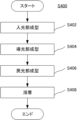
- FIG. 15 shows a fourth manufacturing method flow S400 of the light guide 1d4.
- acrylic resin is used as a molding material for the light guide 1d2.
- the light entrance section 10, the light guide section 20, and the light return section 40 are made of the same material.
- step S402 the light entrance part 10 is molded.
- the light entrance portion 10 can be molded by the steps S201 to S203 described above.
- FIG. 16A shows the configuration of the molded light entrance section 10.
- the light entrance section 10 is formed separately from the light guide section 20 and the light return section 40.
- step S404 the light guide section 20 is molded. Details of molding are omitted.
- FIG. 16B shows the configuration of the molded light guide section 20.
- the light guide section 20 is formed separately from the light entrance section 10 and the light return section 40.
- the light return section 40 is molded.
- the light return section 40 can be molded in the same manner as the light entrance section 10.
- a mold including an internal space having a size and shape capable of accommodating the light return section 40 and having a plurality of grooves arranged in the Y-axis direction and having a cross-sectional shape complementary to the continuous section 71 on the ceiling surface is used. It is placed over a mold in which a plurality of protruding sides having cross-sectional shapes complementary to the spaces 40s and 40t are arranged in the Y-axis direction to form an internal space between them, and the acrylic resin is extracted into the internal space. By doing so, the light return section 40 is formed.
- FIG. 16C shows the configuration of the molded light return section 40.
- the light return unit 40 is a space in which a plurality of light return elements 41 are connected in the Y-axis direction, a continuous part 71 is arranged on the boundary between adjacent light return elements 41 on the +Z plane, and they are arranged in the Y-axis direction on the ⁇ Z plane. 40s and 40t are formed.
- step S406 the light entrance part 10, the light guide part 20, and the light return part 40 are welded to form the light guide body 1d2.
- the light entrance section 10 is arranged on the +Z end surface of the light guide section 20 with one end surface in which the space 30s is formed facing the -Z side
- the light return section 40 is arranged on the +Z end surface of the light guide section 20, with one end surface in which the space 30s is formed facing the -Z side.
- the light guide section 20 is placed on the -Z end surface of the light guide section 20 with one end surface on which the light guide section 40t is formed facing the -Z side.
- the continuous portion 31 integrally molded on the ⁇ Z surface of the light entrance portion 10 comes into contact with the +Z end surface of the light guide portion 20, and the continuous portion 71 integrally molded on the +Z surface of the light return portion 40 contacts the +Z end surface of the light guide portion 20. It comes into contact with the -Z end face of 20.
- ultrasonic vibration is applied to at least one of the light entrance section 10, the light guide section 20, and the light return section 40 to weld them together.
- the light entrance part 10 and the light guide part 20 are joined to each other via the continuous part 31, and the light guide part 20 and the light return part 40 are joined to each other via the continuous part 71, and the light guide 1d2 is formed.
- the light entrance part 10, the light guide part 20, and the light return part 40 may be bonded not only by welding but also by using a solvent, for example.
- the light guide body 1d2 may be molded using a 3D printer.
- the light guide 1d2 is an optical device that guides the light input from the light entrance surface 10a to a light exit surface 20a different from the light entrance surface 10a and outputs it from the light exit surface 20a, and the light is transmitted along the Z axis.
- a light input section 10 having a light input surface 10a that inputs light in the direction, a light guide section 20 that is arranged on the light output surface 20a side and guides light in the Y-axis direction and outputs it from the light output surface 20a, a light input section 10, and a light guide.
- a light return section 40 is provided, which is disposed on the opposite side of the light entrance section 10 to the light section 20 and returns light leaking from the light guide section 20 to the light guide section 20.
- the light returns from the light incident part 10 (condensing element 11) through the area between them and the light guide part 20 without being reflected by the reflecting surfaces 12 and 13.
- FIG. 17 shows the configuration of a light guide 1d3 according to a second modification.
- the light guide 1d3 further includes a bottom portion 48 compared to the light guide 1d2 according to the second embodiment.
- the bottom part 48 is formed into a plate shape whose length is in the Y-axis direction using the same material as the light return part 40, and is fused to the ⁇ Z plane of the light return part 40. Note that the bottom portion 48 and the light return portion 40 may be formed integrally. As a result, leaked light that is not reflected by the reflective surfaces 42 and 43 and leaks to the ⁇ Z side is reflected by the ⁇ Z surface of the bottom portion 48, guided and confined within the bottom portion 48 in the Y-axis direction, and returned to the +Z direction. can.
- FIG. 18 shows the configuration of a light guide 1d4 according to a third modification.
- the light guide 1d4 includes a light return section 40d in which only a space 40s is formed on the -Z plane with respect to the light return section 40 in the light guide 1d2 according to the second embodiment.
- a reflective film made of metal or the like may be provided on the reflective surfaces 42 and 43 so that even if leaked light enters at an angle less than the critical angle, it is totally reflected.
- the reflective surfaces 42 and 43 are curved or bent in a parabolic shape so that the leaked light reflected by the reflective surfaces 42 and 43 is focused on the continuous portion 71 on the boundary between the two light return elements 41 adjacent to the +Y side. You may let them.
- the light returns from the light incident part 10 (condensing element 11) through the area between them and the light guide part 20 without being reflected by the reflecting surfaces 12 and 13.
- the input light that is, the leaked light
- the light guide section 20 By returning the input light, that is, the leaked light, to the light guide section 20, most of the light that has entered the light input section 10 can be confined within the light guide section 20 and output from the light exit surface 20a.
- the light guide section 20 is perpendicular to the input direction of light (Z-axis direction). Although it is described that it is formed into a plate shape extending in the Y-axis direction, it is not limited to this, and may be formed to curve in any direction intersecting the input direction, such as curved in an arc shape or spherical shell shape. . Further, the light guide section 20 may be formed to extend in a curved or bent direction in an arbitrary direction from a portion overlapping with the light entrance section 10, and may be widened or reduced in width, increased in thickness, or reduced in thickness until reaching the light exit surface 20a. It may be formed to extend. Thereby, the light collected by the light input section 10 is guided into the light guide section 20, and then guided toward an arbitrary direction toward the light output surface 20a while being reflected at the end face thereof.
- the light output from the light output surfaces 20a of the light guides 1d2, 1d3, and 1d4 is input to another light guide (such as an optical fiber) different from the light guides 1d2, 1d3, and 1d4, and
- the light may be output (light emitted) at the other end of the body.
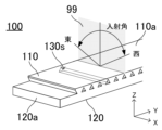
- ⁇ Third embodiment ⁇ 19A and 19B respectively show the overall configuration of a light guide 100 according to the third embodiment, and the configuration of the light entrance section 110 and the boundary section 130 between this and the light guide section 120.
- the light guide 100 is an optical device that efficiently collects light input from a light entrance surface 110a, and guides and outputs the collected light to a light exit surface 120a, which is different from the light entrance surface 110a, without leaking or with little leakage. , a light entrance section 110, a light guide section 120, and a boundary section 130.
- the light guide 100 as a whole has a substantially plate shape that extends in a two-dimensional direction with the short side in the X-axis direction and the long side in the Y-axis direction, and has a thickness in the Z-axis direction.
- the light entrance section 110 is an optical member that focuses light input in the input direction (in the present embodiment, the -Z direction) through the light entrance surface 110a, and has a plurality of light focusing elements 111.
- the plurality of light condensing elements 111 are columnar members that extend in the X-axis direction and have an inverted, generally isosceles trapezoidal cross section with a maximum width P in the Y-axis direction and a height d in the Z-axis direction. That is, they are arranged in parallel in the Y-axis direction with their +Z sides (+Y side and -Y side) in contact with each other, and -Z sides spaced apart from each other.
- the plurality of light condensing elements 111 are connected to each other and integrally molded. (described as including). Thereby, the light entrance section 110 extends in the Y-axis direction, and the +Z planes of the plurality of condensing elements 111 are connected to each other to form a planar light entrance surface 110a having a width in the X-axis direction. In this way, the light entrance surface 110a is provided so that light is input from the +Z side. Further, two adjacent light condensing elements 111 form a hollow space (simply referred to as space) 130s having a triangular cross section and extending in the X-axis direction.
- the plurality of condensing elements 111 may be spaced apart from each other in the Y-axis direction and arranged in parallel. In such a case, each of the +Z planes of the plurality of condensing elements 111 functions as an independent light entrance plane.
- the condensing element 111 has reflective surfaces 112 and 113 and a light-transmitting section 114 located below (-Z direction) with respect to the light incident surface 110a.
- the condensing element 111 is made of, for example, resin having a high refractive index such as acrylic resin (refractive index 1.49) or polycarbonate resin (refractive index 1.58), or glass (for example, a material with a refractive index lower than that of BK7). 1.51 to 1.53).
- the boundary between the condensing element 111 and the space 130s that is, the ⁇ Y side surfaces of the condensing element 111, are reflective surfaces 112 and 113 that reflect a part of the light input into the condensing element 111 via the light entrance surface 110a. functions as When light enters the ⁇ Y sides from inside the condensing element 111 at an angle equal to or greater than the critical angle, it is totally reflected.
- the critical angle is about 42 degrees for acrylic resins, about 41 degrees for polycarbonate resins, and about 42 degrees for glass. Therefore, the ⁇ Y side surfaces of the condensing element 111 are formed such that their normal lines form an angle greater than a critical angle with respect to the light input direction (in this embodiment, the Z-axis direction).
- a portion of the light condensing element 111 between the reflective surfaces 112 and 113 includes a portion of the light input from the light entrance surface 110a (in this example, the remaining portion that does not enter the reflective surfaces 112 and 113) and the reflected light. It functions as a light transmitting part 114 that passes the reflected light reflected by the surfaces 112 and 113.
- the reflective surfaces 112 and 113 are located on the +Y side and the -Y side of the transparent section 114, respectively, and are arranged to face each other, and reflect the light input from the light entrance surface 110a toward the transparent section 114. It is set up like this.
- the reflective surfaces 112 and 113 are formed linearly on the YZ cross section.
- the reflective surfaces 112 and 113 that is, the ⁇ Y side surfaces of the condensing element 111 may be mirror-finished.
- a reflective film may be provided using metal or the like.
- the light guide section 120 has a light exit surface 120a located on the -Z side with respect to the light entrance section 110, and directs the reflected light reflected by the reflective surfaces 112, 113 of the light entrance section 110 in the +Y direction and/or -Y direction. It is an optical member that guides the light in the direction and outputs it from the light output surface 120a.
- the light guide section 120 is formed into a plate shape extending in the Y-axis direction.
- the width of the light guide section 120 in the X-axis direction is equal to (or may be larger than) the width of the light entrance section 110, and the length in the Y-axis direction is greater than (or may be equal to) the length of the light entrance section 110.
- the thickness in the Z-axis direction is larger than the thickness of the light entrance part 110 (which may be arbitrarily determined).
- the +Y side surface and/or the -Y side surface of the light guide section 120 form a light output surface 120a that outputs light, and the -Z end surface 120b is formed in a planar shape to direct the light guided into the light guide section 120 inward. It functions as a reflective surface that reflects light toward the target.
- the light guide section 120 can be formed from the same material as the light entrance section 110 (light condensing element 111). In order to increase the reflectance, the -Z end surface 120b of the light guide section 120 may be mirror-finished. Further, a reflective film may be provided using metal or the like.
- the boundary portion 130 is a portion located at the boundary between the light entrance portion 110 and the light guide portion 120, and includes a continuous portion 131 and a discontinuous portion 132.
- the continuous part 131 is such that the light transmitting part 114 of the light entering part 110 and the light guiding part 120 are physically continuous, and the light inputted from the light entering surface 110a, that is, the reflected light reflected by the reflecting surfaces 112 and 113. The remaining light that did not enter the reflective surfaces 112 and 113 is guided into the light guide section 120.
- the continuous portion 131 has an opening width A in the Y-axis direction and extends in the X-axis direction. Note that the continuous portion 131 can be formed from the same material as the condensing element 111. Further, the continuous portion 131 may be integrally formed with the light entrance portion 110 and/or the light guide portion 120 as a part thereof.
- the discontinuous portion 132 is provided so that the reflective surfaces 112 and 113 of the light entrance portion 110 and the light guide portion 120 are separated from each other, and is disposed adjacent to each of the ⁇ Y sides of the continuous portion 131.
- the discontinuous part 132 separates the light guide part 120 from the light incident part 110 (reflecting surfaces 112 and 113 formed on the ⁇ Y sides) and forms a space 130s between them, so that the discontinuous part 132 and the light guide
- the interface between the light sections 120 functions as a reflecting surface that reflects the reflected light input from the light transmitting section 114 of the light input section 110 to the light guide section 120 via the continuous section 131 and guides it to the light exit surface 120a.
- the interface between the discontinuous portion 132 and the light guide section 120 that is, the +Z end surface of the light guide section 120 below the space 130 may be mirror-finished.
- a reflective film may be provided using metal or the like.
- the reflective surfaces 112 and 113 and the light-transmitting part 114 of the light entrance part 110 are formed by arranging the light collecting elements 111 in parallel in the Y-axis direction to form the light entrance part 110. A plurality of them are arranged along the Y-axis direction. Accordingly, a plurality of continuous parts 131 and a plurality of discontinuous parts 132 are provided at the boundaries of the light entrance part 110 and the light guide part 120, respectively, and a plurality of continuous parts 131 and a plurality of discontinuous parts are provided along the Y-axis direction. 132 are arranged alternately.
- the continuous portions 131 have a width A in the Y-axis direction (equal to the width of the transparent portion 114), and are periodically arranged at a pitch P in the Y-axis direction.
- the discontinuous portion 132 has approximately the same width as the continuous portion 131 and is disposed between the continuous portions 131 .
- the aperture ratio A/P becomes approximately 1/2.
- the reflective surfaces 112 and 113 of the light entrance section 110 reflect the light input from the light entrance surface 110a toward the continuous section 131.
- the reflective surfaces 112 and 113 reflect light input from a direction perpendicular to the light incident surface 110a (in the present embodiment, the Z-axis direction) toward the continuous portion 131.
- the light reflected by the reflective surface 112 forms parallel light and passes through the continuous section 131. That is, the light reflected on the +Z side of the reflective surface 112 passes through the +Y side of the continuous section 131, and passes through the continuous section 131.
- the light reflected at the center of the continuous section 131 passes through the center of the continuous section 131, and the light reflected at the -Z side of the reflective surface 112 passes through the -Y side of the continuous section 131, and then enters the light guide section 120.
- the light reflected by the reflective surface 113 forms parallel light and enters the light guide section 120 in the same way as the light reflected by the reflective surface 112, except that the direction of the light is reversed.
- discontinuous portion 132 is disposed below the reflective surfaces 112 and 113 of the light entrance portion 110, thereby separating the reflective surface 112 and the light guiding portion 120 from each other, and the discontinuous portion 132b separating the reflective surface 112 and the light guiding portion 120. It includes a discontinuous portion 132a that is separated from the portion 120.
- the light condensing elements 111 in parallel in the Y-axis direction within the light entrance part 110, the Y side surfaces of two adjacent light condensing elements 111 and the discontinuous part 132 (+Z end of the light guide part 120) As a result, a space 130s having a triangular cross section when viewed in the Y direction is formed inside them, and the reflective surfaces 112 and 113 of two adjacent condensing elements 111 face each other through the space 130s, and a space 130s is formed below each other.
- the discontinuous portions 132 located therein become continuous.
- the end of the discontinuous portion 132 on the light guide portion 120 side (that is, the interface between the light guide portion 120 and the discontinuous portion 132) is inclined with respect to the Y-axis direction.
- the interface between the light guide section 120 and each of the adjacent discontinuous sections 132 is inclined in different directions with respect to the Y-axis direction.
- the interface between the light guide section 120 and the discontinuous section 132a is inclined in the clockwise direction with respect to the Y axis
- the interface between the light guide section 120 and the discontinuous section 132b is inclined in the counterclockwise direction with respect to the Y axis. tilt.
- the discontinuous parts 132 arranged in the Y-axis direction include discontinuous parts 132a and discontinuous parts 132b arranged alternately.
- the mutually opposing reflecting surfaces 112 and 113 of one condensing element 111 have opposite directions and equal inclination angles with respect to the Z axis.
- the inclination angles may be different for each of the adjacent light condensing elements 111, or may be different alternately.
- the reflective surfaces 112 and 113 facing away from each other across the space 130s between two adjacent condensing elements 111 have different inclination angles.
- the triangular cross sections of the plurality of spaces 130s arranged in the Y-axis direction may be alternately rotated in different directions.
- the rotation of the plurality of spaces 130s is rotation about a reference axis parallel to the X-axis direction passing through the center of the spaces 130s on the YZ plane.
- the left space 130sa rotates clockwise and the right space 130sb counterclockwise with respect to the state before rotation shown by the dotted line in the figure (that is, the state where the base of the triangle is parallel to the Y-axis direction). It is rotating around. Thereby, the spaces 130sa rotated clockwise and the spaces 130sb rotated counterclockwise are arranged alternately in the Y-axis direction.
- the boundary part 130 between the light entrance part 110 and the light guide part 120 forms a straight line extending in the Y-axis direction within the YZ plane, and the continuous part 131 and the discontinuous part 132 also form a straight line. It continues linearly in the YZ plane.
- the boundary portion 130 repeatedly bends in the ⁇ Z direction within the YZ plane to form a non-straight line extending in the Y-axis direction, and the continuous portion 131 and the discontinuous portion 132 also become non-linear within the YZ plane. Continuous in a shape.
- FIG. 20 shows how the light input to the light guide 1 is collected by the light input section 110 and guided by the light guide section 120.
- the optical path of light that enters the -Z direction from the light entrance surface 110a and is reflected at the reflection surface 113 of the light entrance section 110 (the right inclined surface of the leftmost space 130sa in the drawing) is shown.
- the aperture width A of the continuous portion 131 is large (aperture ratio A/P ⁇ 0.5)
- the light reflected by the reflective surface 113 passes through the continuous portion 131 while maintaining parallel light. , enters the light guide section 120.
- the reflected light that has entered the light guide section 120 is reflected by the -Z end surface 120b of the light guide section 120 and returns to the +Z direction, and is reflected by the discontinuous section 132, in this example, three points to the right of the space 130sa below the reflective surface 113. It is reflected at the interface with the discontinuous portion 132b under the adjacent space 130sb, reflected at the -Z end surface 120b of the light guide section 120, and returns to the +Z direction, and then the discontinuous portion 132b under the adjacent space 130sb two spaces to the right. The light is reflected at the interface, is guided to the right inside the light guide section 120, and is output from the light output surface 120a.
- the interfaces between the discontinuous parts 132 (discontinuous parts 132a, 132b) arranged in the Y-axis direction and the light guide part 120 are alternately tilted in different directions, so that the condensing elements 111 are further arranged in the Y-axis direction. Since the reflecting surfaces 112 and 113 have different inclination angles (absolute value of the inclination angle with respect to the Z axis) alternately, the light reflected by the reflecting surface 113 is transmitted to the same discontinuous portion 132 (in this example, the discontinuous portion 132b) and is guided within the light guide section 120.
- a plurality of discontinuous sections 132 are provided.
- the inclination angles of the discontinuous portions 132a and 132b and/or the inclination angles of the reflective surfaces 112 and 113 are determined so that the light is reflected at the interface.
- the light guide 100 according to the third embodiment can be manufactured in the same manner as the light guide 1 according to the first embodiment.
- FIG. 21 shows a light guide assembly 100a according to the third embodiment.
- the light guide assembly 100a includes two light guides 100 stacked in the Z-axis direction.
- the upper light guide 100 is arranged on the light incident surface 110a of the lower light guide 100.
- a slight gap is provided between the light incident surface 110a of the lower light guide 100 and the -Z plane of the upper light guide 100.
- the lower light guide 100 is arranged on the opposite side of the light entrance part 110 with respect to the light guide part 120 of the upper light guide 100 in the Z-axis direction, so that the light passing through the upper light guide part 120 is It is also an example of a light condensing unit provided so that light is input.
- the light entrance section 110 is formed to be rotationally symmetrical by 180 degrees with respect to the Z-axis direction.
- a reflective surface 112 is located at the +Y end surface
- a reflective surface 113 is located at the -Y end surface.
- the light guide section 120 is also formed to be rotationally symmetrical by 180 degrees with respect to the Z-axis direction.
- the difference from the distance L 113 is approximately equal to the width of the continuous portion 131 and the discontinuous portion 132 in the Y-axis direction, that is, one half of the arrangement pitch P of the plurality of condensing elements 111.
- the lower light guide 100 is arranged to be rotated by 180 degrees with respect to the Z axis with respect to the upper light guide 100.
- the reflective surface 113 is located at the +Y end surface of the light entrance section 110, and the reflective surface 112 is located at the -Y end surface.
- the upper light guide 100 is placed on the light incident surface 110a of the lower light guide 100, and the ⁇ Y end faces of the light guides 100 are aligned.
- the light condensing elements 111 of the upper light guide 100 are arranged offset by P/2 in the Y-axis direction with respect to the light condensing elements 111 of the lower light guide 100.
- the reflective surfaces 112 and 113 of the plurality of light-condensing elements 111 of the lower light guide 100 are located below the light-transmitting portions 114 of the plurality of light-collecting elements 111 (in the -Z direction), respectively.
- FIG. 22 shows the principle of condensing the light input to the light guide assembly 100a by the light entrance part 110 and guiding the light by the light guide part 120.
- the light is not reflected by the reflective surfaces 112 and 113 of the light incident part 110 of the upper light guide 100, but is transmitted through the light transmitting part 114 between them (the light transmitting part 114 of the condensing element 111 on the left side of the drawing). shows the optical path of light entering the light guide section 120. Note that the guide of the light entering the reflective surfaces 112 and 113 of the light entrance section 110 is as described above using FIG. 2.
- the light enters the ⁇ Z direction from the light incident surface 110a.
- the reflective surfaces 112 and 113 of the lower light guide 100 are located below the light transmitting part 114 of the upper light guide 100, the light passing through the +Y side of the upper light transmitting part 114 is , is reflected by the reflection surface 113 on the +Y side in the lower stage, passes through the continuous part 131 while maintaining parallel light, and enters the light guide part 120 in the lower stage.
- the reflected light that has entered the light guide section 120 is reflected by the -Z end surface 120b of the light guide section 120 and the interface between the light guide section 120 and the discontinuous section 132, as described above with reference to FIG.
- the light is guided to the right inside the light section 120 and output from the light output surface 120a.
- the light (not shown) that has passed through the -Y side of the upper transparent section 114 is reflected by the -Y side reflective surface 112 of the lower section, passes through the adjacent continuous section 131 while maintaining parallel light, and then passes through the adjacent continuous section 131 to the lower section.
- the light enters the light guide section 120 of.
- the reflected light that has entered the light guide section 120 is guided to the left within the light guide section 120 and output from the other light exit surface 120a.
- FIG. 23 shows the configuration and light collection principle of a light guide assembly 100b according to a modification.
- the light guide assembly 100b includes three light guides 100 stacked in the Z-axis direction.
- the middle light guide 100 is arranged on the light entrance surface 110a of the lower light guide 100
- the upper light guide 100 is arranged on the light entrance surface 110a of the middle light guide 100.
- a slight gap is provided between the three light guides 100.
- the continuous part 131 has twice the width of the discontinuous part 132, and the three light guides 100 have their respective condensing elements 111 offset by P/3 in the Y-axis direction. Arranged.
- the reflective surfaces 112 and 113 of the light-concentrating elements 111 of the middle and lower light guides 100 are located below the light-transmitting portion 114 of the light-concentrating element 111 of the upper light guide 100 (in the -Z direction). That will happen.
- lights I11 and I12 are reflected by the reflective surfaces 112 and 113 of the light incident section 110 at the upper stage, respectively, and are guided inside the light guide section 120 at the upper stage. , are output from the light exit surface 120a.
- the lights I21 and I22 that pass through the -Y side are reflected by the reflective surfaces 112 and 113 of the light entrance section 110 at the middle stage, respectively.
- Lights I31 and I32 that are reflected and guided through the middle light guide section 120 and pass through the +Y side are reflected by the reflective surfaces 112 and 113 of the lower light entrance section 110, respectively, and then travel inside the lower light guide section 120.
- the light is guided and output from the light exit surface 120a of each light guide 100.
- the widths of the reflective surfaces 112 and 113 of the light entrance part 110 and the continuous part 131 are changed (1:N-1), and the light guide 100 is stacked in multiple (N) stages, and the width is set by P/N in the Y-axis direction.
- the light guide assembly may also be configured in an offset arrangement.
- the light guide 100 is a light guide that guides light input from a light entrance surface 110a to a light exit surface 120a and outputs it from the light exit surface 120a. It has a light surface 110a, reflective surfaces 112 and 113 located in the ⁇ Z direction with respect to the light entrance surface 110a, and a transparent part 114, and the reflection surfaces 112 and 113 absorb part of the light input from the light entrance surface 110a.
- the light-transmitting part 114 transmits another part of the light input from the light-entering surface 110a and the reflected light reflected by the reflecting surfaces 112 and 113.
- a light guide section 120 which has a light exit surface 120a located on the -Z side and guides the reflected light in the Y-axis direction and outputs it from the light exit surface 120a, is arranged at the boundary of the light input section 110 and the light guide section 120, respectively.
- a continuous part 131 is provided so that the light transmitting part 114 and the light guide part 120 are continuous
- a discontinuous part 132 is provided so that the reflective surfaces 112 and 113 and the light guide part 120 are separated from each other. According to this, a part of the light input in the -Z direction through the light entrance surface 110a of the light entrance section 110 is reflected by the reflection surfaces 112 and 113 of the light entrance section 110, and the reflected light is transmitted to the light entrance section.
- the light guide assembly 100a includes two light guides 100 stacked in the Z-axis direction. According to this, the light transmitting part 114 and the light guide part 120 between them are transmitted from the 100 light incident parts 110 (concentrating elements 111) of the upper light guide without being reflected by the reflective surfaces 112 and 113. By concentrating the light emitted outside the light guide 100 through the light guide 100, that is, the leaked light, by the lower light guide 100, most of the light that has entered the light guide assembly 100a is confined within the light guide 120, and the light exit surface It can be output from 120a.
- the upper surface (the light entrance surface 110a of the light entrance section 110) and the lower surface (-Z plane of the light guide section 120) of the light guide 100 according to the third embodiment may be smooth surfaces. Thereby, it is possible to prevent the accumulation of dust and the like when the light guide 100 is installed outdoors.
- the light guide section 120 is formed in a plate shape so as to extend in the Y-axis direction perpendicular to the light input direction (Z-axis direction).
- the shape is not limited to this, and may be curved in any direction intersecting the input direction, such as in an arc shape or a spherical shell shape.
- the light guide section 120 may be formed to extend in a curved or bent direction in an arbitrary direction from a portion overlapping with the light entrance section 110, and may be widened or reduced in width, increased in thickness, or reduced in thickness until reaching the light exit surface 120a. It may be formed to extend. Thereby, the light collected by the light entrance part 110 is guided into the light guide part 120, and then guided in an arbitrary direction toward the light exit surface 120a while being reflected by the end face thereof.
- the light output from the light emitting surface 120a of the light guide 100 is input to another light guide (such as an optical fiber) different from the light guide 100, and is output ( (light emission).
- another light guide such as an optical fiber
Landscapes
- Physics & Mathematics (AREA)
- General Physics & Mathematics (AREA)
- Optics & Photonics (AREA)
- Life Sciences & Earth Sciences (AREA)
- Sustainable Development (AREA)
- Engineering & Computer Science (AREA)
- General Engineering & Computer Science (AREA)
- Health & Medical Sciences (AREA)
- Toxicology (AREA)
- Light Guides In General And Applications Therefor (AREA)
- Optical Couplings Of Light Guides (AREA)
Priority Applications (5)
| Application Number | Priority Date | Filing Date | Title |
|---|---|---|---|
| JP2024530996A JPWO2024005191A1 (https=) | 2022-07-01 | 2023-06-30 | |
| CN202380044394.8A CN119301399A (zh) | 2022-07-01 | 2023-06-30 | 导光体 |
| KR1020247039857A KR20250048653A (ko) | 2022-07-01 | 2023-06-30 | 도광체 |
| EP23831630.1A EP4549811A1 (en) | 2022-07-01 | 2023-06-30 | Light guide |
| US18/969,151 US20250093630A1 (en) | 2022-07-01 | 2024-12-04 | Light guide |
Applications Claiming Priority (2)
| Application Number | Priority Date | Filing Date | Title |
|---|---|---|---|
| JP2022-107298 | 2022-07-01 | ||
| JP2022107298 | 2022-07-01 |
Related Child Applications (1)
| Application Number | Title | Priority Date | Filing Date |
|---|---|---|---|
| US18/969,151 Continuation US20250093630A1 (en) | 2022-07-01 | 2024-12-04 | Light guide |
Publications (1)
| Publication Number | Publication Date |
|---|---|
| WO2024005191A1 true WO2024005191A1 (ja) | 2024-01-04 |
Family
ID=89382561
Family Applications (1)
| Application Number | Title | Priority Date | Filing Date |
|---|---|---|---|
| PCT/JP2023/024402 Ceased WO2024005191A1 (ja) | 2022-07-01 | 2023-06-30 | 導光体 |
Country Status (6)
| Country | Link |
|---|---|
| US (1) | US20250093630A1 (https=) |
| EP (1) | EP4549811A1 (https=) |
| JP (1) | JPWO2024005191A1 (https=) |
| KR (1) | KR20250048653A (https=) |
| CN (1) | CN119301399A (https=) |
| WO (1) | WO2024005191A1 (https=) |
Citations (3)
| Publication number | Priority date | Publication date | Assignee | Title |
|---|---|---|---|---|
| JP2008251468A (ja) | 2007-03-30 | 2008-10-16 | Kyocera Corp | 集光素子と採光装置 |
| JP2012038626A (ja) * | 2010-08-09 | 2012-02-23 | Sony Corp | 光学素子およびその製造方法ならびに照明装置、窓材および建具 |
| JP2015143864A (ja) * | 2015-02-16 | 2015-08-06 | 大日本印刷株式会社 | 採光シート、採光装置、及び建物 |
Family Cites Families (2)
| Publication number | Priority date | Publication date | Assignee | Title |
|---|---|---|---|---|
| US8152339B2 (en) * | 2007-05-01 | 2012-04-10 | Morgan Solar Inc. | Illumination device |
| US8412010B2 (en) * | 2007-09-10 | 2013-04-02 | Banyan Energy, Inc. | Compact optics for concentration and illumination systems |
-
2023
- 2023-06-30 JP JP2024530996A patent/JPWO2024005191A1/ja active Pending
- 2023-06-30 EP EP23831630.1A patent/EP4549811A1/en active Pending
- 2023-06-30 WO PCT/JP2023/024402 patent/WO2024005191A1/ja not_active Ceased
- 2023-06-30 KR KR1020247039857A patent/KR20250048653A/ko active Pending
- 2023-06-30 CN CN202380044394.8A patent/CN119301399A/zh active Pending
-
2024
- 2024-12-04 US US18/969,151 patent/US20250093630A1/en active Pending
Patent Citations (3)
| Publication number | Priority date | Publication date | Assignee | Title |
|---|---|---|---|---|
| JP2008251468A (ja) | 2007-03-30 | 2008-10-16 | Kyocera Corp | 集光素子と採光装置 |
| JP2012038626A (ja) * | 2010-08-09 | 2012-02-23 | Sony Corp | 光学素子およびその製造方法ならびに照明装置、窓材および建具 |
| JP2015143864A (ja) * | 2015-02-16 | 2015-08-06 | 大日本印刷株式会社 | 採光シート、採光装置、及び建物 |
Also Published As
| Publication number | Publication date |
|---|---|
| US20250093630A1 (en) | 2025-03-20 |
| KR20250048653A (ko) | 2025-04-10 |
| EP4549811A1 (en) | 2025-05-07 |
| JPWO2024005191A1 (https=) | 2024-01-04 |
| CN119301399A (zh) | 2025-01-10 |
Similar Documents
| Publication | Publication Date | Title |
|---|---|---|
| KR101455892B1 (ko) | 광 에너지의 집광, 집결 및 조명을 위한 소형 광소자 | |
| JP5944400B2 (ja) | 集熱及び照明システム用のコンパクトな光学部品 | |
| US8498505B2 (en) | Dimpled light collection and concentration system, components thereof, and methods | |
| US8189970B2 (en) | Light collecting and emitting apparatus, method, and applications | |
| US9246038B2 (en) | Light collecting and emitting apparatus, method, and applications | |
| IL106092A (en) | A lighting system with an aspherical lens and a method of manufacturing it | |
| EP2519978B1 (en) | Photovoltaic concentrator with optical stepped lens and method for designing the same | |
| CN107533236A (zh) | 光学设备 | |
| JP2010539428A6 (ja) | 光エネルギーを集束、集合及び照明する小型光学素子 | |
| CN103238091A (zh) | 用于聚集和照明系统的变向光学装置 | |
| US20110203662A1 (en) | Stepped flow-line concentrators and collimators | |
| CN103038577B (zh) | 光导太阳能模块及其制造方法和由其制成的电池板 | |
| CN1885129B (zh) | 照明装置及显示装置 | |
| WO2024005191A1 (ja) | 導光体 | |
| JP5116535B2 (ja) | レーザー溶着方法 | |
| JP5655146B2 (ja) | 集光型レンズアレイおよびそれを備えた太陽電池 | |
| CN120826566A (zh) | 导光体及导光体组件 | |
| US20120206826A1 (en) | Light-collecting device and light-collecting method thereof | |
| TWI783088B (zh) | 光學元件以及光學系統裝置 | |
| JPH0776826B2 (ja) | レンチキュラースクリーンおよびその製造方法 | |
| CN116232214A (zh) | 聚光方法,利用其的聚光装置及太阳能发电机 | |
| JP2009198524A (ja) | 太陽レンズ | |
| JP2009258371A (ja) | 光導入装置、集光ユニット、及び集光装置 | |
| JPH04191802A (ja) | 導波路型光学素子 | |
| JPS6152411B2 (https=) |
Legal Events
| Date | Code | Title | Description |
|---|---|---|---|
| 121 | Ep: the epo has been informed by wipo that ep was designated in this application |
Ref document number: 23831630 Country of ref document: EP Kind code of ref document: A1 |
|
| WWE | Wipo information: entry into national phase |
Ref document number: 2024530996 Country of ref document: JP |
|
| WWE | Wipo information: entry into national phase |
Ref document number: 202380044394.8 Country of ref document: CN |
|
| WWE | Wipo information: entry into national phase |
Ref document number: 202417101271 Country of ref document: IN |
|
| WWP | Wipo information: published in national office |
Ref document number: 202380044394.8 Country of ref document: CN |
|
| WWE | Wipo information: entry into national phase |
Ref document number: 2023831630 Country of ref document: EP |
|
| NENP | Non-entry into the national phase |
Ref country code: DE |
|
| ENP | Entry into the national phase |
Ref document number: 2023831630 Country of ref document: EP Effective date: 20250203 |
|
| WWP | Wipo information: published in national office |
Ref document number: 1020247039857 Country of ref document: KR |
|
| WWP | Wipo information: published in national office |
Ref document number: 2023831630 Country of ref document: EP |