WO2024005010A1 - Terminal device, method, and integrated circuit - Google Patents
Terminal device, method, and integrated circuit Download PDFInfo
- Publication number
- WO2024005010A1 WO2024005010A1 PCT/JP2023/023784 JP2023023784W WO2024005010A1 WO 2024005010 A1 WO2024005010 A1 WO 2024005010A1 JP 2023023784 W JP2023023784 W JP 2023023784W WO 2024005010 A1 WO2024005010 A1 WO 2024005010A1
- Authority
- WO
- WIPO (PCT)
- Prior art keywords
- scg
- rrc
- bfd
- terminal device
- mac
- Prior art date
Links
- 238000000034 method Methods 0.000 title claims abstract description 112
- 238000012545 processing Methods 0.000 claims abstract description 171
- 230000011664 signaling Effects 0.000 claims abstract description 125
- 238000001514 detection method Methods 0.000 claims description 17
- 230000004913 activation Effects 0.000 abstract description 18
- 230000004044 response Effects 0.000 abstract description 8
- 230000006870 function Effects 0.000 description 85
- 230000008569 process Effects 0.000 description 38
- 230000005540 biological transmission Effects 0.000 description 34
- 238000005516 engineering process Methods 0.000 description 25
- 238000004891 communication Methods 0.000 description 20
- 238000012544 monitoring process Methods 0.000 description 20
- 238000010586 diagram Methods 0.000 description 17
- 238000011084 recovery Methods 0.000 description 16
- 101100150275 Caenorhabditis elegans srb-3 gene Proteins 0.000 description 15
- 230000002779 inactivation Effects 0.000 description 15
- 238000005259 measurement Methods 0.000 description 15
- 101000946053 Homo sapiens Lysosomal-associated transmembrane protein 4A Proteins 0.000 description 13
- 102100034728 Lysosomal-associated transmembrane protein 4A Human genes 0.000 description 13
- 101001055444 Homo sapiens Mediator of RNA polymerase II transcription subunit 20 Proteins 0.000 description 11
- 102100026165 Mediator of RNA polymerase II transcription subunit 20 Human genes 0.000 description 11
- 230000009977 dual effect Effects 0.000 description 11
- 108091005487 SCARB1 Proteins 0.000 description 10
- 102100037118 Scavenger receptor class B member 1 Human genes 0.000 description 10
- 230000009849 deactivation Effects 0.000 description 7
- 230000003213 activating effect Effects 0.000 description 6
- 230000007704 transition Effects 0.000 description 6
- 239000000872 buffer Substances 0.000 description 5
- 238000013507 mapping Methods 0.000 description 5
- 230000006978 adaptation Effects 0.000 description 4
- 230000002457 bidirectional effect Effects 0.000 description 4
- 230000001413 cellular effect Effects 0.000 description 4
- 230000006835 compression Effects 0.000 description 4
- 238000007906 compression Methods 0.000 description 4
- 238000010295 mobile communication Methods 0.000 description 4
- 230000014509 gene expression Effects 0.000 description 3
- 235000019527 sweetened beverage Nutrition 0.000 description 3
- 230000001960 triggered effect Effects 0.000 description 3
- 101000652482 Homo sapiens TBC1 domain family member 8 Proteins 0.000 description 2
- 101150071746 Pbsn gene Proteins 0.000 description 2
- 102100030302 TBC1 domain family member 8 Human genes 0.000 description 2
- 230000020411 cell activation Effects 0.000 description 2
- 230000008859 change Effects 0.000 description 2
- 238000012937 correction Methods 0.000 description 2
- 239000004065 semiconductor Substances 0.000 description 2
- 241000700159 Rattus Species 0.000 description 1
- 230000002776 aggregation Effects 0.000 description 1
- 238000004220 aggregation Methods 0.000 description 1
- 238000004378 air conditioning Methods 0.000 description 1
- 238000004140 cleaning Methods 0.000 description 1
- 238000004590 computer program Methods 0.000 description 1
- 125000004122 cyclic group Chemical group 0.000 description 1
- 230000006837 decompression Effects 0.000 description 1
- 238000013461 design Methods 0.000 description 1
- 238000011161 development Methods 0.000 description 1
- 230000018109 developmental process Effects 0.000 description 1
- 230000000694 effects Effects 0.000 description 1
- 238000011156 evaluation Methods 0.000 description 1
- 230000006266 hibernation Effects 0.000 description 1
- 230000000415 inactivating effect Effects 0.000 description 1
- 230000000977 initiatory effect Effects 0.000 description 1
- 230000007774 longterm Effects 0.000 description 1
- 238000012423 maintenance Methods 0.000 description 1
- 230000003287 optical effect Effects 0.000 description 1
- 230000000737 periodic effect Effects 0.000 description 1
- 230000002093 peripheral effect Effects 0.000 description 1
- 239000000725 suspension Substances 0.000 description 1
- 238000012546 transfer Methods 0.000 description 1
- 238000012795 verification Methods 0.000 description 1
- 238000005406 washing Methods 0.000 description 1
Images


Classifications
-
- H—ELECTRICITY
- H04—ELECTRIC COMMUNICATION TECHNIQUE
- H04W—WIRELESS COMMUNICATION NETWORKS
- H04W16/00—Network planning, e.g. coverage or traffic planning tools; Network deployment, e.g. resource partitioning or cells structures
- H04W16/24—Cell structures
- H04W16/28—Cell structures using beam steering
-
- H—ELECTRICITY
- H04—ELECTRIC COMMUNICATION TECHNIQUE
- H04W—WIRELESS COMMUNICATION NETWORKS
- H04W72/00—Local resource management
- H04W72/04—Wireless resource allocation
- H04W72/044—Wireless resource allocation based on the type of the allocated resource
- H04W72/0457—Variable allocation of band or rate
-
- H—ELECTRICITY
- H04—ELECTRIC COMMUNICATION TECHNIQUE
- H04W—WIRELESS COMMUNICATION NETWORKS
- H04W76/00—Connection management
- H04W76/10—Connection setup
- H04W76/18—Management of setup rejection or failure
Definitions
- the present invention relates to a terminal device, a method, and an integrated circuit.
- This application claims priority to Japanese Patent Application No. 2022-104494 filed in Japan on June 29, 2022, the contents of which are incorporated herein.
- the 3rd Generation Partnership Project (3GPP) which is a standardization project for cellular mobile communication systems, is conducting technical studies and standardization for cellular mobile communication systems, including wireless access, core networks, services, etc. There is.
- E-UTRA Evolved Universal Terrestrial Radio Access
- RAT Radio Access Technology
- 3GPP 3GPP is still conducting technical studies and standardization for E-UTRA expansion technology.
- E-UTRA is also referred to as Long Term Evolution (LTE: registered trademark), and the extended technology is also referred to as LTE-Advanced (LTE-A) and LTE-Advanced Pro (LTE-A Pro).
- LTE Long Term Evolution
- LTE-A LTE-Advanced
- LTE-A Pro LTE-Advanced Pro
- NR New Radio, or NR Radio access
- 5G 5th Generation
- 3GPP TS 38.331 v17.0.0 Evolved Universal Terrestrial Radio Access (E-UTRA);Radio Resource Control (RRC);Protocol specifications” pp70-116,pp218-223,pp316-1107 3GPP TS 38.321 v17.0.0, "NR;Medium Access Control (MAC) protocol specification” pp17-104 3GPP TS 38.213 v17.2.0, “NR; Physical layer procedures for control” pp14-20
- dual connectivity also referred to as multi-connectivity
- dual connectivity in which one or more base station devices and terminal devices communicate using multiple cell groups
- SCG deactivation secondary cell group deactivation
- TRPs Transmission Reception Points
- One aspect of the present invention has been made in view of the above circumstances, and one of the objects is to provide a terminal device, a base station device, a communication method, and an integrated circuit that can efficiently control communication. .
- one embodiment of the present invention takes the following measures. That is, one aspect of the present invention is a terminal device that communicates with a base station device, which includes a PHY processing unit, a MAC processing unit that performs MAC layer processing, an RRC processing unit, and receiving signaling from the base station device. a receiving unit, the RRC processing unit notifying the MAC processing unit that the secondary cell group (SCG) is to be activated based on receiving the signaling indicating that the SCG is to be activated. , when the MAC processing unit is notified by the RRC processing unit that the SCG will be activated, the MAC processing unit transmits one or more reference signals for beam failure detection to the PSCell of the SCG.
- a base station device which includes a PHY processing unit, a MAC processing unit that performs MAC layer processing, an RRC processing unit, and receiving signaling from the base station device.
- the RRC processing unit notifying the MAC processing unit that the secondary cell group (SCG) is to be activated based on receiving
- BFD-RS set It is determined whether multiple BFD-RS sets are configured as a set (BFD-RS set), and when it is determined that multiple BFD-RS sets are configured for the PSCell, the It is determined whether the value of the counter associated with each of the BFD-RS sets set for the PSCell is greater than or equal to a threshold value, and Based on the determination that all the values of the counters linked to each are equal to or higher than the threshold, the RRC processing unit is notified that it is necessary to execute a random access procedure in order to activate the SCG, and the The PHY processing unit notifies the MAC processing unit of a beam failure instance for each set of BFD-RS, the counter is prepared for each BFD-RS set of the PSCell in which the BFD-RS set is configured, It is used to count beam failure instances notified from the PHY processing unit.
- one aspect of the present invention is a method for a terminal device communicating with a base station device, the method being applied to the terminal device communicating with the base station device, the method including the step of receiving signaling from the base station device.
- RRC layer processing a step of notifying the MAC layer that the secondary cell group (SCG) is to be activated based on receiving the signaling indicating that the SCG is to be activated; and MAC layer processing.
- SCG secondary cell group
- MAC layer processing When the RRC layer notifies that the SCG will be activated, one set (BFD-RS set) of one or more reference signals for beam failure detection is sent to the PSCell of the SCG.
- the processing includes a step of notifying a MAC layer of a beam failure instance for each set of BFD-RS, and the counter is prepared for each BFD-RS set of the PSCell in which the BFD-RS set is configured. , is used to count beam failure instances notified from the PHY layer.
- one aspect of the present invention is an integrated circuit mounted on a terminal device communicating with a base station device, the integrated circuit mounted on a terminal device communicating with the base station device, the integrated circuit receiving signaling from the base station device. and a function of notifying the MAC layer to activate the secondary cell group (SCG) based on the reception of the signaling indicating that the secondary cell group (SCG) is to be activated as processing of the RRC layer.
- SCG secondary cell group
- the MAC layer when it is notified from the RRC layer that the SCG will be activated, one set of one or more reference signals for beam failure detection is sent to the PSCell of the SCG.
- BFD-RS set a function to determine whether or not multiple BFD-RS sets are configured, and when it is determined that multiple BFD-RS sets are configured for the PSCell, A function for determining whether the value of a counter associated with each of the BFD-RS sets set for the PSCell is equal to or greater than a threshold; A function that notifies the RRC layer that it is necessary to execute a random access procedure to activate the SCG based on the determination that all counter values associated with each RS set are equal to or higher than a threshold value. and a function of notifying the MAC layer of a beam failure instance for each set of BFD-RS as processing of the PHY layer, is prepared for each BFD-RS set, and is used to count beam failure instances notified from the PHY layer.
- a terminal device, a method, and an integrated circuit can realize efficient communication control processing.
- FIG. 1 is a schematic diagram of a communication system according to the present embodiment.
- FIG. 2 is a diagram illustrating an example of the E-UTRA protocol configuration according to the present embodiment.
- FIG. 3 is a diagram illustrating an example of the NR protocol configuration according to the present embodiment.
- FIG. 3 is a diagram illustrating an example of a flow of procedures for various settings in RRC according to the present embodiment.
- FIG. 2 is a block diagram showing the configuration of a terminal device in this embodiment.
- FIG. 2 is a block diagram showing the configuration of a base station device in this embodiment.
- LTE and LTE-A, LTE-A Pro
- NR may be defined as different radio access technologies (RAT).
- LTE which can be connected to NR using Multi-Radio Dual Connectivity (MR-DC)
- MR-DC Multi-Radio Dual Connectivity
- LTE that uses 5GC in the core network may be distinguished from conventional LTE that uses EPC in the core network.
- CN Core Network
- conventional LTE may be LTE that does not implement the technology standardized after Release 15 in 3GPP.
- This embodiment may be applied to NR, LTE and other RATs.
- the present embodiment may be applied to technologies using other terms and/or other radio access technologies.
- E-UTRA and the term LTE in this embodiment may be interchanged with each other.
- each node and entity and the processing in each node and entity will be explained when the radio access technology is E-UTRA or NR. However, this embodiment is applicable to other radio access technologies. may be applied. The names of each node and entity in this embodiment may be different names.
- FIG. 1 is a schematic diagram of a communication system according to this embodiment. Note that the functions of each node, radio access technology, core network, interface, etc. explained using FIG. 1 are some functions closely related to this embodiment, and may have other functions.
- E-UTRA100 may be a radio access technology. Further, the E-UTRA 100 may be an air interface between the UE 122 and the eNB 102. The air interface between UE 122 and eNB 102 may be referred to as a Uu interface.
- the eNB (E-UTRAN Node B) 102 may be a base station device of the E-UTRA 100.
- the eNB 102 may have the E-UTRA protocol described below.
- the E-UTRA protocol may be composed of the E-UTRA User Plane (UP) protocol, which will be described later, and the E-UTRA Control Plane (CP) protocol, which will be described later.
- the eNB 102 may terminate the E-UTRA user plane (UP) protocol and the E-UTRA control plane (CP) protocol for the UE 122.
- a radio access network composed of eNBs may be called E-UTRAN.
- the EPC (Evolved Packet Core) 104 may be a core network.
- Interface 112 is an interface between eNB 102 and EPC 104, and may be called an S1 interface.
- the interface 112 may include a control plane interface through which control signals pass and/or a user plane interface through which user data passes.
- the control plane interface of interface 112 may terminate at a Mobility Management Entity (MME: not shown) within EPC 104 .
- MME Mobility Management Entity
- S-GW serving gateway
- the control plane interface of interface 112 may be referred to as the S1-MME interface.
- the user plane interface of interface 112 may be referred to as the S1-U interface.
- one or more eNBs 102 may be connected to the EPC 104 via the interface 112.
- An interface may exist between multiple eNBs 102 connected to the EPC 104 (not shown).
- the interface between the plurality of eNBs 102 connected to the EPC 104 may be referred to as an X2 interface.
- NR106 may be a radio access technology.
- NR106 may also be an air interface between UE122 and gNB108.
- the air interface between UE 122 and gNB 108 may be referred to as a Uu interface.
- gNB (g Node B) 108 may be a base station device of NR106.
- gNB 108 may have the NR protocol described below.
- the NR protocol may be composed of the NR User Plane (UP) protocol, which will be described later, and the NR Control Plane (CP) protocol, which will be described later.
- the gNB 108 may terminate the NR User Plane (UP) protocol and the NR Control Plane (CP) protocol for the UE 122.
- UP NR User Plane
- CP NR Control Plane
- 5GC110 may be a core network.
- Interface 116 is an interface between gNB 108 and 5GC 110, and may be called an NG interface.
- the interface 116 may include a control plane interface through which control signals pass and/or a user plane interface through which user data passes.
- the control plane interface of interface 116 may terminate in an Access and Mobility Management Function (AMF: not shown) within 5GC 110.
- AMF Access and Mobility Management Function
- the user plane interface of interface 116 may terminate at a User Plane Function (UPF: not shown) within 5GC 110.
- the control plane interface of interface 116 may be referred to as an NG-C interface.
- the user plane interface of interface 116 may be referred to as an NG-U interface.
- one or more gNBs 108 may be connected to the 5GC 110 via the interface 116.
- An interface may exist between multiple gNBs 108 connected to 5GC 110 (not shown).
- the interface between multiple gNBs 108 connected to 5GC 110 may be called an Xn interface.
- eNB102 may have the ability to connect to 5GC110.
- the eNB 102 that has the function of connecting to the 5GC 110 may be called an ng-eNB.
- Interface 114 is an interface between eNB 102 and 5GC 110, and may be called an NG interface.
- the interface 114 may include a control plane interface through which control signals pass and/or a user plane interface through which user data passes.
- the control plane interface of interface 114 may terminate at an AMF within 5GC 110.
- the user plane interface of interface 114 may terminate at a UPF within 5GC 110.
- the control plane interface of interface 114 may be referred to as an NG-C interface.
- the user plane interface of interface 114 may be referred to as an NG-U interface.
- a radio access network composed of ng-eNBs or gNBs may be referred to as NG-RAN.
- NG-RAN, E-UTRAN, etc. may also be simply referred to as networks.
- the network may include eNB, ng-eNB, gNB, and the like.
- one or more eNBs 102 may be connected to the 5GC 110 via the interface 114.
- An interface may exist between multiple eNBs 102 connected to 5GC 110 (not shown).
- the interface between multiple eNBs 102 connected to 5GC 110 may be called an Xn interface.
- the eNB 102 connected to the 5GC 110 and the gNB 108 connected to the 5GC 110 may be connected through an interface 120.
- the interface 120 between the eNB 102 that connects to the 5GC 110 and the gNB 108 that connects to the 5GC 110 may be called an Xn interface.
- gNB108 may have the function of connecting to EPC104.
- gNB 108 having the function of connecting to EPC 104 may be called en-gNB.
- Interface 118 is an interface between gNB 108 and EPC 104, and may be called an S1 interface.
- Interface 118 may include a user plane interface through which user data passes.
- the user plane interface of interface 118 may terminate at an S-GW (not shown) within EPC 104.
- the user plane interface of interface 118 may be referred to as the S1-U interface.
- the eNB 102 connected to the EPC 104 and the gNB 108 connected to the EPC 104 may be connected through an interface 120.
- the interface 120 between the eNB 102 that connects to the EPC 104 and the gNB 108 that connects to the EPC 104 may be called an X2 interface.
- the interface 124 is an interface between the EPC 104 and the 5GC 110, and may be an interface that passes only CP, only UP, or both CP and UP. Furthermore, some or all of the interfaces 114, 116, 118, 120, 124, etc. may not exist depending on the communication system provided by the communication carrier or the like.
- the UE 122 may be a terminal device that can receive system information and paging messages transmitted from the eNB 102 and/or gNB 108. Further, the UE 122 may be a terminal device capable of wirelessly connecting with the eNB 102 and/or the gNB 108. Further, the UE 122 may be a terminal device that can simultaneously perform a wireless connection with the eNB 102 and a wireless connection with the gNB 108. UE 122 may have an E-UTRA protocol and/or an NR protocol. Note that the wireless connection may be a Radio Resource Control (RRC) connection.
- RRC Radio Resource Control
- the UE 122 may be a terminal device that can be connected to the EPC 104 and/or 5GC 110 via the eNB 102 and/or gNB 108.
- each data radio bearer (DRB) established between UE122 and eNB102 and/or gNB108 (to be described later) ) may be uniquely associated with each EPS (Evolved Packet System) bearer passing through the EPC 104.
- EPS Evolved Packet System
- Each EPS bearer may be identified by an EPS bearer identifier (Identity, or ID).
- the same QoS may be guaranteed for data such as IP packets and Ethernet (registered trademark) frames that pass through the same EPS bearer.
- each DRB established between UE122 and eNB102 and/or gNB108 is further established within 5GC110. It may be linked to one of the PDU (Packet Data Unit) sessions. There may be one or more QoS flows in each PDU session. Each DRB may be mapped with one or more QoS flows, or may not be mapped with any QoS flows.
- Each PDU session may be identified by a PDU session identifier (Identity, or ID). Further, each QoS flow may be identified by a QoS flow identifier (Identity or ID). Furthermore, the same QoS may be guaranteed for data such as IP packets and Ethernet frames passing through the same QoS flow.
- the EPC 104 There may be no PDU sessions and/or QoS flows in the EPC 104. Also, 5GC110 does not need to have an EPS bearer. When the UE 122 is connected to the EPC 104, the UE 122 has information on the EPS bearer, but may not have information on the PDU session and/or QoS flow. Further, when the UE 122 is connected to the 5GC 110, the UE 122 has information on the PDU session and/or QoS flow, but does not need to have information on the EPS bearer.
- the eNB 102 and/or gNB 108 will also be simply referred to as a base station device, and the UE 122 will also be simply referred to as a terminal device or UE.
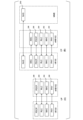
- FIG. 2 is a diagram of an example of the E-UTRA protocol architecture according to the present embodiment.
- FIG. 3 is a diagram of an example of the NR protocol configuration according to the present embodiment. Note that the functions of each protocol explained using FIG. 2 and/or FIG. 3 are some functions closely related to this embodiment, and may have other functions.
- the uplink (UL) may be a link from a terminal device to a base station device.
- the downlink (DL) may be a link from a base station device to a terminal device.
- FIG. 2(A) is a diagram of the E-UTRA user plane (UP) protocol stack.
- the E-UTRA UP protocol may be a protocol between the UE 122 and the eNB 102. That is, the E-UTRA UP protocol may be a protocol that terminates at the eNB 102 on the network side.
- the E-UTRA user plane protocol stack consists of a wireless physical layer (PHY) 200, a medium access control layer (MAC) 200, and a medium access control layer (MAC).
- RLC Radio Link Control
- PDCP Packet Data Convergence Protocol
- Figure 3(A) is a diagram of the NR user plane (UP) protocol stack.
- the NRUP protocol may be a protocol between the UE 122 and the gNB 108. That is, the NR UP protocol may be a protocol that terminates at the gNB 108 on the network side.
- the NR user plane protocol stack consists of PHY300, which is the radio physical layer, MAC302, which is the medium access control layer, RLC304, which is the radio link control layer, PDCP306, which is the packet data convergence protocol layer, and It may be configured from SDAP (Service Data Adaptation Protocol) 310, which is a service data adaptation protocol layer.
- SDAP Service Data Adaptation Protocol
- FIG. 2(B) is a diagram of the E-UTRA control plane (CP) protocol configuration.
- RRC Radio Resource Control
- NAS Non Access Stratum
- the NAS 210 may be a protocol that terminates with the MME on the network side.
- Figure 3(B) is a diagram of the NR control plane (CP) protocol configuration.
- RRC 308 which is a radio resource control layer
- RRC308 may be a protocol that terminates at gNB108 on the network side.
- the NAS 312, which is a non-AS layer may be a protocol between the UE 122 and the AMF. That is, the NAS 312 may be a protocol that terminates with AMF on the network side.
- the AS (Access Stratum) layer may be a layer that terminates between the UE 122 and the eNB 102 and/or gNB 108. That is, the AS layer is a layer that includes some or all of PHY200, MAC202, RLC204, PDCP206, and RRC208, and/or a layer that includes some or all of PHY300, MAC302, RLC304, PDCP306, SDAP310, and RRC308. It's fine.
- the following does not distinguish between the E-UTRA protocol and the NR protocol, and uses PHY (PHY layer), MAC (MAC layer), RLC (RLC layer), PDCP (PDCP layer), and RRC (RRC layer).
- NAS NAS layer
- PHY (PHY layer), MAC (MAC layer), RLC (RLC layer), PDCP (PDCP layer), RRC (RRC layer), and NAS (NAS layer) are the PHY (PHY layer) of the E-UTRA protocol.
- the SDAP (SDAP layer) may be the SDAP (SDAP layer) of the NR protocol.
- PHY200, MAC202, RLC204, PDCP206, and RRC208 are respectively referred to as PHY for E-UTRA or PHY for LTE, MAC for E-UTRA, or It is also called MAC for LTE, RLC for E-UTRA or RLC for LTE, PDCP for E-UTRA or PDCP for LTE, and RRC for E-UTRA or RRC for LTE. and PHY200, MAC202, RLC204, PDCP206, and RRC208, respectively. It may also be written as LTE RRC.
- PHY300, MAC302, RLC304, PDCP306, and RRC308 are called PHY for NR, MAC for NR, RLC for NR, RLC for NR, and RRC for NR, respectively.
- PHY300, MAC302, RLC304, PDCP306, and RRC308 may also be written as NR PHY, NR MAC, NR RLC, NR PDCP, NR RRC, etc., respectively.
- Entities in the AS layer of E-UTRA and/or NR will be explained.
- An entity that has some or all of the functions of the MAC layer may be called a MAC entity.
- An entity that has some or all of the functions of the RLC layer may be called an RLC entity.
- An entity that has some or all of the functions of the PDCP layer may be called a PDCP entity.
- An entity that has some or all of the functions of the SDAP layer may be called an SDAP entity.
- An entity that has some or all of the functions of the RRC layer may be called an RRC entity.
- the MAC entity, RLC entity, PDCP entity, SDAP entity, and RRC entity may be replaced with MAC, RLC, PDCP, SDAP, and RRC, respectively.
- MAC PDU Protocol Data Unit
- RLC Network Data Unit
- RLC Physical Location
- SDAP Secure Protocol
- data provided from upper layers to MAC, RLC, PDCP, and SDAP and/or data provided from MAC, RLC, PDCP, and SDAP to upper layers are MAC SDU (Service Data Unit) and RLC SDU, respectively.
- MAC SDU Service Data Unit
- RLC SDU Service Data Unit
- PDCP SDU Secure Data Unit
- SDAP SDU Secure Data Unit
- a segmented RLC SDU may be referred to as an RLC SDU segment.
- the base station device and the terminal device exchange (transmit and receive) signals in a higher layer.
- a higher layer may also be referred to as an upper layer, and may be interchanged with each other.
- a base station device and a terminal device may transmit and receive an RRC message (also referred to as RRC signalling) in a radio resource control (RRC) layer.
- RRC radio resource control
- the base station device and the terminal device may transmit and receive MAC control elements in the MAC (Medium Access Control) layer.
- the RRC layer of the terminal device acquires system information broadcast from the base station device.
- the RRC message, system information, and/or MAC control element are also referred to as higher layer signals (higher layer signaling) or higher layer parameters (higher layer parameters).
- each of the parameters included in the upper layer signal received by the terminal device may be referred to as an upper layer parameter.
- the upper layer means the upper layer seen from the PHY layer, so one or more of the MAC layer, RRC layer, RLC layer, PDCP layer, NAS (Non Access Stratum) layer, etc. It can mean that.
- the upper layer may mean one or more of the RRC layer, RLC layer, PDCP layer, NAS layer, and the like.
- a is given (provided) by the upper layer” and “A is given (provided) by the upper layer” mean the upper layers of the terminal device (mainly the RRC layer and MAC layer). etc.) may mean that A is received from the base station device, and the received A is given (provided) from an upper layer of the terminal device to the physical layer of the terminal device.
- being “provided with upper layer parameters” means that the upper layer parameter included in the received upper layer signal is received from the base station device, and the upper layer parameter included in the received upper layer signal is transmitted from the upper layer of the terminal device to the terminal device. It may also mean provided in layers.
- Setting upper layer parameters to a terminal device may mean that upper layer parameters are given (provided) to the terminal device.
- setting upper layer parameters in a terminal device may mean that the terminal device receives an upper layer signal from a base station device and sets the received upper layer parameters in the upper layer.
- setting upper layer parameters to the terminal device may include setting default parameters given in advance to the upper layer of the terminal device.
- the expression "submit" a message from the RRC entity of the terminal device to a lower layer may be used.
- "submitting a message to a lower layer” from an RRC entity may mean submitting a message to a PDCP layer.
- submitting a message from the RRC layer to a lower layer means that RRC messages are sent using SRBs (SRB0, SRB1, SRB2, SRB3, etc.), so It may also mean submitting to the corresponding PDCP entity.
- the RRC entity of the terminal device receives an indication from a lower layer, the lower layer may refer to one or more of the PHY layer, MAC layer, RLC layer, PDCP layer, etc.
- the PHY of the terminal device may have a function of receiving data transmitted from the PHY of the base station device via a downlink (DL) physical channel.
- the PHY of the terminal device may have a function of transmitting data to the PHY of the base station device via an uplink (UL) physical channel.
- the PHY may be connected to the upper MAC via a transport channel.
- the PHY may pass data to the MAC via a transport channel.
- the PHY may also be provided with data from the MAC via a transport channel.
- RNTI Radio Network Temporary Identifier
- the physical channels used for wireless communication between the terminal device and the base station device may include the following physical channels.
- PBCH Physical Broadcast CHannel
- PDCCH Physical Downlink Control CHannel
- PDSCH Physical Downlink Shared CHannel
- PUCCH Physical Uplink Control CHannel
- PUSCH Physical Uplink Shared CHannel
- PRACH Physical Random Access CHannel
- PBCH may be used to broadcast system information required by terminal devices.
- the PBCH may be used to broadcast a time index (SSB-Index) within the period of a synchronization signal block (SSB).
- SSB-Index time index within the period of a synchronization signal block
- the PDCCH may be used to transmit (or carry) downlink control information (DCI) in downlink wireless communication (wireless communication from a base station device to a terminal device).
- DCI downlink control information
- one or more DCIs (which may also be referred to as DCI formats) may be defined for transmission of downlink control information. That is, a field for downlink control information may be defined as DCI and mapped to information bits.
- PDCCH may be transmitted on PDCCH candidates.
- a terminal device may monitor a set of PDCCH candidates in a serving cell. Monitoring a set of PDCCH candidates may mean attempting to decode a PDCCH according to a certain DCI format.
- the terminal device monitors PDCCH candidates in configured monitoring occasions within one or more configured control resource sets (CORESET) configured by the search space configuration. It's fine.
- the DCI format may be used for PUSCH scheduling in the serving cell.
- PUSCH may be used for transmitting user data, transmitting an RRC message, which will be described later, and the like.
- PDCCH repetition may be operated by using two search space sets explicitly linked by the configuration provided by the upper layer (RRC layer). Two linked search space sets may also be associated with a corresponding CORESET. For PDCCH repetition, two linked search space sets may be configured in the terminal device with the same number of PDCCH candidates. Two PDCCH candidates existing in two linked search space sets may be linked by the same candidate index. When PDCCH repetition is scheduled to a terminal device, inter-slot repetition may be allowed, and each repetition consists of the same number of Control Channel Elements (CCEs) and coded bits. ), and may have the same DCI payload.
- CCEs Control Channel Elements
- the PUCCH may be used to transmit uplink control information (UCI) in uplink wireless communication (wireless communication from a terminal device to a base station device).
- the uplink control information may include channel state information (CSI) used to indicate the state of a downlink channel.
- the uplink control information may also include a scheduling request (SR) used to request UL-SCH (Uplink Shared CHannel) resources.
- SR scheduling request
- the uplink control information may include HARQ-ACK (Hybrid Automatic Repeat reQuest ACKnowledgement).
- the PDSCH may be used to transmit downlink data (DL-SCH: Downlink Shared CHannel) from the MAC layer. Further, in the case of downlink, the PDSCH may be used to transmit system information (SI), random access response (RAR), and the like.
- SI system information
- RAR random access response
- PUSCH may be used to transmit HARQ-ACK and/or CSI along with uplink data (UL-SCH: Uplink Shared CHannel) or uplink data from the MAC layer. Further, PUSCH may be used to transmit only CSI or only HARQ-ACK and CSI. That is, PUSCH may be used to transmit only UCI. Further, the PDSCH or PUSCH may be used to transmit an RRC message and a MAC CE, which will be described later.
- the RRC message transmitted from the base station device may be common signaling to multiple terminal devices within the cell. Furthermore, the RRC message transmitted from the base station device may be dedicated signaling for a certain terminal device. That is, UE specific information may be transmitted to a certain terminal device using dedicated signaling. Further, PUSCH may be used to transmit UE Capability in the uplink.
- PRACH may be used to transmit a random access preamble.
- PRACH is used to indicate initial connection establishment procedures, handover procedures, connection re-establishment procedures, synchronization (timing adjustment) for uplink transmission, and requests for UL-SCH resources. It's okay.
- MAC may also be called a MAC sublayer.
- the MAC may have a function of mapping various logical channels to corresponding transport channels.
- a logical channel may be identified by a logical channel identifier (Logical Channel Identity, or Logical Channel ID).
- Logical Channel ID Logical Channel Identity
- the MAC may be connected to the upper RLC through a logical channel.
- Logical channels may be divided into control channels for transmitting control information and traffic channels for transmitting user information, depending on the type of information to be transmitted. Further, logical channels may be divided into uplink logical channels and downlink logical channels.
- the MAC may have a function of multiplexing MAC SDUs belonging to one or more different logical channels and providing the same to the PHY.
- the MAC may also have a function of demultiplexing the MAC PDUs provided from the PHY and providing them to the upper layer via the logical channel to which each MAC SDU belongs.
- the MAC may also have a function of performing error correction through HARQ (Hybrid Automatic Repeat reQuest).
- the MAC may also have a scheduling report (SR) function that reports scheduling information.
- the MAC may have a function of performing priority processing between terminal devices using dynamic scheduling. Further, the MAC may have a function of performing priority processing between logical channels within one terminal device.
- the MAC may have a function to prioritize resources that overlap within one terminal device.
- E-UTRA MAC may have the function of identifying Multimedia Broadcast Multicast Services (MBMS).
- MBMS Multimedia Broadcast Multicast Services
- the NR MAC may also have a function of identifying multicast/broadcast service (MBS).
- the MAC may have the ability to select the transport format.
- MAC has the function of performing discontinuous reception (DRX) and/or discontinuous transmission (DTX), the function of performing random access (RA) procedure, the function of notifying information on transmittable power, and the power It may have a headroom report (PHR) function, a buffer status report (BSR) function that notifies information on the amount of data in the transmission buffer, etc.
- NR MAC may have a Bandwidth Adaptation (BA) function.
- BA Bandwidth Adaptation
- the MAC PDU format used in E-UTRA MAC and the MAC PDU format used in NR MAC may be different.
- the MAC PDU may also include a MAC control element (MAC control element: MAC CE), which is an element for controlling the MAC.
- MAC control element MAC control element
- the BCCH (Broadcast Control Channel) may be a downlink logical channel for broadcasting control information such as system information (SI).
- SI system information
- PCCH Packet Control Channel
- PCCH Packet Control Channel
- CCCH Common Control Channel
- CCCH may be a logical channel for transmitting control information between a terminal device and a base station device.
- CCCH may be used when the terminal device does not have an RRC connection. Further, CCCH may be used between a base station device and multiple terminal devices.
- DCCH Dedicated Control Channel
- the dedicated control information may be control information dedicated to each terminal device.
- DCCH may be used when the terminal device has an RRC connection.
- DTCH (Dedicated Traffic Channel) may be a logical channel for transmitting user data on a one-to-one (point-to-point) basis between a terminal device and a base station device.
- DTCH may be a logical channel for transmitting dedicated user data.
- the dedicated user data may be user data dedicated to each terminal device.
- DTCH may exist on both uplink and downlink.
- CCCH may be mapped to UL-SCH (Uplink Shared Channel), which is an uplink transport channel.
- UL-SCH Uplink Shared Channel
- the DCCH may be mapped to a UL-SCH (Uplink Shared Channel), which is an uplink transport channel.
- UL-SCH Uplink Shared Channel
- DTCH may be mapped to UL-SCH (Uplink Shared Channel), which is an uplink transport channel.
- UL-SCH Uplink Shared Channel
- the BCCH may be mapped to a BCH (Broadcast Channel), which is a downlink transport channel, and/or a DL-SCH (Downlink Shared Channel).
- BCH Broadcast Channel
- DL-SCH Downlink Shared Channel
- the PCCH may be mapped to a PCH (Paging Channel), which is a downlink transport channel.
- PCH Packet Control Channel
- CCCH may be mapped to DL-SCH (Downlink Shared Channel), which is a downlink transport channel.
- DL-SCH Downlink Shared Channel
- the DCCH may be mapped to a DL-SCH (Downlink Shared Channel), which is a downlink transport channel.
- DL-SCH Downlink Shared Channel
- DTCH may be mapped to DL-SCH (Downlink Shared Channel), which is a downlink transport channel.
- DL-SCH Downlink Shared Channel
- RLC may also be called an RLC sublayer.
- the E-UTRA RLC may have a function of segmenting and/or concatenating data provided from the upper layer PDCP and providing it to the lower layer.
- the E-UTRA RLC may have a function of reassembling and re-ordering data provided from lower layers and providing the data to upper layers.
- NR RLC may have a function of adding a sequence number independent of the sequence number added by PDCP to data provided from the upper layer PDCP.
- NR RLC may have a function of segmenting data provided from PDCP and providing it to lower layers.
- the NR RLC may have a function of reassembling data provided from lower layers and providing the data to upper layers.
- RLC may also have a data retransmission function and/or a retransmission request function (AutomaticRepeat reQuest: ARQ). Additionally, RLC may have a function of performing error correction using ARQ. Control information indicating data that needs to be retransmitted, which is sent from the RLC receiving side to the transmitting side in order to perform ARQ, can be called a status report. Also, the status report transmission instruction sent from the RLC transmitting side to the receiving side can be referred to as a poll. The RLC may also have a function to detect data duplication. RLC may also have a data discard function. RLC may have three modes: transparent mode (TM), unacknowledged mode (UM), and acknowledged mode (AM).
- TM transparent mode
- UM unacknowledged mode
- AM acknowledged mode
- the TM does not divide data received from the upper layer and does not need to add an RLC header.
- a TM RLC entity is a uni-directional entity and may be configured as a transmitting TM RLC entity or as a receiving TM RLC entity.
- data received from the upper layer is divided and/or combined, RLC headers are added, etc., but there is no need to control data retransmission.
- a UM RLC entity may be a unidirectional entity or a bi-directional entity. If the UM RLC entity is a unidirectional entity, the UM RLC entity may be configured as a transmitting UM RLC entity or as a receiving UM RLC entity.
- the UM RRC entity may be configured as a UM RLC entity consisting of a transmitting side and a receiving side.
- the AM RLC entity is a bidirectional entity and may be configured as an AM RLC consisting of a transmitting side and a receiving side.
- data provided by the TM to a lower layer and/or data provided from a lower layer may be referred to as a TMD PDU.
- data provided to lower layers in UM and/or data provided from lower layers may be referred to as UMD PDU.
- data provided to lower layers in AM or data provided from lower layers may be referred to as AMD PDU.
- the RLC PDU format used in E-UTRA RLC and the RLC PDU format used in NR RLC may be different.
- the RLC PDU may include a data RLC PDU and a control RLC PDU.
- the RLC PDU for data may be called RLC DATA PDU (RLC Data PDU, RLC data PDU).
- the control RLC PDU may be referred to as RLC CONTROL PDU (RLC Control PDU, RLC control PDU, RLC control PDU).
- PDCP may be called a PDCP sublayer.
- PDCP may have a function to perform sequence number maintenance.
- PDCP may have a header compression/decompression function for efficiently transmitting user data such as IP packets and Ethernet frames over a wireless section.
- the protocol used to compress and decompress the header of IP packets can be called the ROHC (Robust Header Compression) protocol.
- the protocol used for compressing and decompressing Ethernet frame headers may be referred to as the EHC (Ethernet (registered trademark) Header Compression) protocol.
- EHC Errnet (registered trademark) Header Compression
- PDCP may have data encryption/decryption functions.
- PDCP may have data integrity protection/integrity verification functions.
- PDCP may also have a re-ordering function.
- PDCP may also have a PDCP SDU retransmission function.
- PDCP may have a function of discarding data using a discard timer.
- PDCP may have a multiplexing (Duplication) function.
- PDCP may have a function of discarding data that has been received repeatedly.
- the PDCP entity is a bidirectional entity and may consist of a transmitting PDCP entity and a receiving PDCP entity.
- the PDCP PDU format used in E-UTRA PDCP and the PDCP PDU format used in NR PDCP may be different.
- the PDCP PDU may include a data PDCP PDU and a control PDCP PDU.
- the data PDCP PDU may be called a PDCP DATA PDU (PDCP Data PDU).
- the control PDCP PDU may be called a PDCP CONTROL PDU (PDCP Control PDU, PDCP control PDU, PDCP control PDU).
- SDAP is a service data adaptation protocol layer.
- SDAP maps the downlink QoS flow sent from 5GC110 to the terminal device via the base station device and the data radio bearer (DRB), and/or the mapping from the terminal device to the terminal device via the base station device. It may have a function to map uplink QoS flows sent to 5GC110 and DRB.
- SDAP may also have a function of storing mapping rule information.
- SDAP may also have a function of marking a QoS flow identifier (QoS Flow ID: QFI).
- QFI QoS flow ID
- the SDAP PDU may include a data SDAP PDU and a control SDAP PDU.
- SDAP PDU for data may be called SDAP DATA PDU (SDAP Data PDU, SDAP data PDU).
- control SDAP PDU may be called an SDAP CONTROL PDU (SDAP Control PDU, SDAP control PDU, SDAP control PDU). Note that one SDAP entity of the terminal device may exist for a PDU session.
- RRC may have a broadcast function.
- the RRC may have a paging function from the EPC 104 and/or 5GC 110.
- the RRC may have a paging function from the eNB 102 that connects to the gNB 108 or 5GC 110.
- RRC may also have RRC connection management functionality.
- RRC may also have radio bearer control functionality.
- the RRC may also have a cell group control function.
- the RRC may also have mobility control functionality.
- the RRC may also have terminal device measurement reporting and terminal device measurement reporting control functions.
- RRC may also have QoS management functionality.
- RRC may also have radio link failure detection and recovery functionality.
- RRC uses RRC messages to perform broadcasting, paging, RRC connection management, radio bearer control, cell group control, mobility control, terminal device measurement reporting and terminal device measurement reporting control, QoS management, radio link failure detection and recovery, etc. You may do so. Note that the RRC messages and parameters used in E-UTRA RRC may be different from the RRC messages and parameters used in NR RRC.
- the RRC message may be sent using the BCCH of a logical channel, the PCCH of a logical channel, the CCCH of a logical channel, or the DCCH of a logical channel. May be sent. Furthermore, RRC messages sent using the DCCH are referred to as dedicated RRC signaling or RRC signaling.
- the RRC message sent using the BCCH may include, for example, a master information block (MIB), each type of system information block (SIB), and other RRC messages may be included.
- RRC messages sent using the PCCH may include, for example, paging messages or other RRC messages.
- RRC messages sent in the uplink (UL) direction using CCCH include, for example, RRC Setup Request message, RRC Resume Request message, RRC Reestablishment Request message, It may include an RRC system information request message (RRC System Info Request), etc. Further, for example, an RRC Connection Request message, an RRC Connection Resume Request message, an RRC Connection Reestablishment Request message, etc. may be included. Other RRC messages may also be included.
- RRC messages sent in the downlink (DL) direction using CCCH include, for example, RRC Connection Reject message, RRC Connection Setup message, RRC Connection Reestablishment message, It may include an RRC Connection Reestablishment Reject message, etc. Further, for example, an RRC rejection message (RRC Reject), an RRC Setup message (RRC Setup), etc. may be included. Other RRC messages may also be included.
- RRC signaling sent in the uplink (UL) direction using DCCH includes, for example, measurement report messages, RRC Connection Reconfiguration Complete messages, and RRC Connection Setup Complete messages. ), an RRC Connection Reestablishment Complete message, a Security Mode Complete message, a UE Capability Information message, and the like. Also, for example, measurement report message (Measurement Report), RRC Reconfiguration Complete message, RRC Setup Complete message, RRC Reestablishment Complete message, RRC Resume Complete message. ), a security mode complete message (Security Mode Complete), a UE Capability Information message, and the like may be included. Other RRC signaling may also be included.
- RRC signaling sent in the downlink (DL) direction using DCCH includes, for example, RRC Connection Reconfiguration message, RRC Connection Release message, Security Mode Command message, It may include a UE Capability Inquiry message, etc. Also, for example, RRC Reconfiguration message, RRC Resume message, RRC Release message, RRC Reestablishment message, Security Mode Command message, UE capability inquiry message. (UE Capability Inquiry) etc. may be included. Other RRC signaling may also be included.
- the NAS may have an authentication function.
- the NAS may also have the ability to perform mobility management.
- the NAS may also have security control functions.
- the UE 122 connecting to the EPC or 5GC may be in the RRC_CONNECTED state when the RRC connection has been established.
- the state in which the RRC connection is established may include a state in which the UE 122 holds some or all of the UE context described below. Further, the state in which the RRC connection is established may include a state in which the UE 122 can transmit and/or receive unicast data.
- the UE 122 when the RRC connection is suspended, the UE 122 may be in the RRC_INACTIVE state. Further, the UE 122 may enter the RRC_INACTIVE state when the UE 122 is connected to the 5GC and the RRC connection is suspended.
- the UE 122 may be in the RRC_IDLE state.
- the E-UTRAN may start suspending the RRC connection.
- the UE 122 may transition to the RRC_IDLE state while retaining the UE's AS context and an identifier (resumeIdentity) used for resuming.
- the layer above the RRC layer of the UE 122 (for example, the NAS layer) is configured such that the UE 122 maintains the UE's AS context, the E-UTRAN permits the return of the RRC connection, and the UE 122 leaves the RRC_IDLE state.
- recovery of the suspended RRC connection may be initiated.
- the definition of pause may be different between the UE 122 connecting to the EPC 104 and the UE 122 connecting to the 5GC 110. Also, when the UE122 is connected to the EPC (when the UE122 is inactive in the RRC_IDLE state) and when the UE122 is connected to the 5GC (when the UE122 is inactive in the RRC_INACTIVE state), the UE122 Some or all of the steps for returning from hibernation may be different.
- RRC_CONNECTED state may be respectively referred to as connected state (connected mode), inactive state (inactive mode), and idle state (idle mode), and RRC connected state (RRC connected mode) , RRC inactive mode, and RRC idle mode.
- the AS context of the UE held by the UE122 includes the current RRC settings, the current security context, the PDCP state including the ROHC (RObust Header Compression) state, and the C-RNTI (Cell Radio) used in the PCell of the connection source (Source).
- the information may include all or part of the Network Temporary Identifier, cell identifier (cellIdentity), and physical cell identifier of the connection source PCell.
- the UE AS context held by any or all of eNB 102 and gNB 108 may include the same information as the UE AS context held by UE 122, or the information contained in the UE AS context held by UE 122. may contain information different from that.
- the security context includes the encryption key at the AS level, the NH (Next Hop parameter), the NCC (Next Hop Chaining Counter parameter) used to derive the next hop access key, the identifier of the selected AS-level encryption algorithm, and replay protection.
- the information may include all or part of the counters used for.
- a serving cell may be configured from one primary cell (PCell).
- multiple serving cells include one or more special cells (Special Cell: SpCell) and one or more all secondary cells. It may mean a set of cells (set of cells) consisting of cells (Secondary Cell: SCell).
- the SpCell may support PUCCH transmission and contention-based Random Access (CBRA), and the SpCell may be activated at all times.
- the PCell may be a cell used in an RRC connection establishment procedure when a terminal device in an RRC idle state transitions to an RRC connected state. Further, the PCell may be a cell used in an RRC connection re-establishment procedure in which a terminal device re-establishes an RRC connection. Further, the PCell may be a cell used in a random access procedure during handover. The PSCell may be a cell used in a random access procedure when adding a secondary node, which will be described later. Further, SpCell may be a cell used for purposes other than those described above.
- the serving cell group configured for the terminal device is composed of an SpCell and one or more SCells, it may be considered that carrier aggregation (CA) is configured for the terminal device. . Further, for a terminal device in which CA is configured, a cell that provides additional radio resources to SpCell may mean SCell.
- CA carrier aggregation
- a cell group that is set from a base station device to a terminal device will be explained.
- a cell group may be composed of one SpCell.
- a cell group may be composed of one SpCell and one or more SCells. That is, a cell group may be composed of one SpCell and optionally one or more SCells. Further, a cell group may be expressed as a set of cells.
- Dual Connectivity means that a first base station device (first node) and a second base station device (second node) perform data communication using the radio resources of the cell groups that they configure. It can be technology.
- a cell group may be added to the terminal device from the base station device.
- the first base station device may add a second base station device.
- the first base station device may be called a master node (MN).
- MN master node
- MCG master cell group
- the second base station device may be referred to as a secondary node (SN).
- a cell group constituted by a secondary node may be referred to as a secondary cell group (SCG).
- the master node and the secondary node may be configured within the same base station device.
- a cell group configured in a terminal device may be referred to as an MCG.
- the SpCell set in the terminal device may be a PCell.
- an NR without a DC configured may be called an NR standalone (NR SA).
- Multi-Radio Dual Connectivity may be a technology that performs DC using E-UTRA for MCG and NR for SCG. Further, MR-DC may be a technique for performing DC using NR for MCG and E-UTRA for SCG. Furthermore, MR-DC may be a technology that performs DC using NR on both MCG and SCG. MR-DC may be a technology included in DC. As an example of MR-DC that uses E-UTRA for MCG and NR for SCG, there may be EN-DC (E-UTRA-NR Dual Connectivity) that uses EPC for the core network, and NGEN-DC that uses 5GC for the core network. There may be DC (NG-RAN E-UTRA-NR Dual Connectivity).
- NR-DC that uses NR for MCG and E-UTRA for SCG
- NE-DC NR-E-UTRA Dual Connectivity
- NR-DC NR-NR Dual Connectivity
- one MAC entity may exist for each cell group.
- a DC or MR-DC when configured in a terminal device, there may be one MAC entity for MCG and one MAC entity for SCG.
- a MAC entity for MCG in a terminal device may always be established in the terminal device in all states (RRC idle state, RRC connected state, RRC inactive state, etc.).
- the MAC entity for the SCG in the terminal device may be created by the terminal device when the SCG is configured in the terminal device.
- the MAC entity for each cell group of the terminal device may be configured by the terminal device receiving RRC signaling from the base station device.
- SpCell When a MAC entity is associated with an MCG, SpCell may refer to PCell.
- SpCell may mean a primary SCG cell (Primary SCG Cell: PSCell). Also, if the MAC entity is not associated with a cell group, SpCell may mean PCell. PCell, PSCell, and SCell are serving cells.
- the MAC entity for MCG may be an E-UTRA MAC entity
- the MAC entity for SCG may be an NR MAC entity.
- the MAC entity for MCG may be an NR MAC entity
- the MAC entity for SCG may be an E-UTRA MAC entity.
- both the MAC entities for MCG and SCG may be NR MAC entities. Note that the fact that one MAC entity exists for each cell group may be translated into the fact that one MAC entity exists for each SpCell. Furthermore, one MAC entity for each cell group may be replaced with one MAC entity for each SpCell.
- the terminal device may adjust the uplink transmission timing. For example, the terminal device may adjust the uplink transmission timing based on reception of a MAC TA command (Timing Advance command).
- a group of serving cells configured by RRC that uses the same timing reference cell and the same timing advance value for the cells to which uplinks are configured. It may be called a group (Timing Advance Group: TAG).
- TAG Timing Advance Group
- a TAG including SpCell of a MAC entity may be referred to as a primary timing advance group (PTAG).
- PTAGs other than the above-mentioned PTAG may be referred to as a secondary timing advance group (STAG). Note that one or more TAGs may be configured independently for each cell group, which will be described later.
- an additional TAG other than PTAG may be set in the terminal device.
- the additional TAG may be configured to be associated with a different physical cell identifier than the serving cell. Further, the additional TAG may be set in association with one of a plurality of TRPs set in a terminal device, which will be described later.
- the terminal device determines the uplink transmission timing for transmission of PUSCH, SRS, and/or PUCCH in some or all serving cells in that TAG. may be adjusted.
- the uplink transmission timing may be adjusted to be T_TA earlier than the timing of the beginning of the downlink frame with the same frame number.
- T_TA may be calculated based on N_TA and TA offset (N_TA,offset).
- N_TA may be set based on information included in the TA command.
- the TA offset (N_TA,offset) may be set based on the RRC parameter (n-TimingAdvanceOffset) set in the terminal device for each serving cell.
- N_TA,offset is set for each serving cell
- N_TA,offset may take the same value in serving cells of the same TAG.
- an independent value of N_TA,offset may be taken for each TRP in a certain TAG. In this case, the uplink transmission timing may be different for each TRP in one TAG.
- cells in each cell group may belong to different TAGs. That is, the PTAG of the MCG and the PTAG of the SCG may be independent and different TAGs.
- the RRC of the terminal device may set the value of a time alignment timer (timeAlignmentTimer) to the MAC in order to maintain uplink time alignment.
- the time adjustment timer may be used to control the time at which the MAC entity considers the uplink time of the serving cell belonging to the TAG associated with the time adjustment timer to be adjusted.
- the value of the time adjustment timer may be set from the base station device to the terminal device by RRC signaling.
- the terminal device's MAC is determined based on the Timing Advance Command (TAC) MAC CE received and the N_TA of the TAG specified in the TAC MAC CE maintained. TAC may be applied to TAG.
- the MAC of the terminal device receives the Timing Advance Command (TAC) MAC CE, and based on the fact that the N_TA of the TAG specified by the TAC MAC CE is maintained, The time alignment timer (timeAlignmentTimer) associated with the specified TAG may be started, or restarted if already running.
- the MAC of the terminal device may perform some or all of the following processes (A) to (G) when the time adjustment timer associated with the PTAG expires.
- A Flush all HARQ buffers for all serving cells (in a cell group).
- B If PUCCH is configured, notify RRC that it has released PUCCH for all serving cells.
- C If SRS is configured, notify RRC that it has released SRS for all serving cells.
- D Clear all Configured downlink assignments and Configured uplink grants.
- E Clear all PUSCH for semi-persistent CSI reporting.
- All time adjustment timers, including STAG, are considered to have expired.
- G Maintain N_TA of all TAGs.
- the MAC of the terminal device may perform some or all of the following processes (A) to (F) on all serving cells belonging to this STAG.
- F Maintain N_TA for this TAG.
- the terminal device Based on the expiration of the time adjustment timer associated with the PTAG, the terminal device performs uplink transmission in all serving cells except for random access preamble transmission in SpCell and MSGA transmission (in 2-step RACH). Not executed.
- the multiple Transmit/Receive Point (also referred to as multi-TRP or mTRP) operation is explained.
- a serving cell receives terminal equipment from multiple TRPs (Transmit/Receive Points) to provide better coverage, reliability, and/or data rate for PDSCH, PDCCH, PUSCH, and PUCCH. Good to be able to schedule.
- TRPs Transmit/Receive Points
- the two operation modes may be single-DCI and multi-DCI. Control of uplink and downlink operations for both modes may be performed at the PHY and MAC layers with settings configured by the RRC layer.
- single-DCI mode a terminal device may be scheduled for both TRPs by the same DCI.
- multi-DCI mode a terminal device may be scheduled for each TRP by an independent DCI.
- Each TRP of mTRPs may be specified by TRP information.
- the TRP information may be information for identifying one TRP among one or more TRPs.
- the TRP information may be an index for identifying one TRP.
- one TRP may be determined based on TRP information.
- the TRP information may be information for identifying one or more TRPs.
- TRP information may be used to select one TRP.
- the TRP information may be a CORESET pool index.
- One CORESET pool index and one CORESET resource set identifier may be associated with one CORESET.
- the terminal device may transmit the PUSCH with the corresponding TRP based on the CORESET resource set identifier.
- TRP information may be associated with an index of a CORESET resource pool.
- a first CORESET pool index may be associated with a first TRP
- a second CORESET pool index may be associated with a second TRP.
- TRP information may be associated with a TCI state pool (or a TCI state pool index).
- a first TCI state pool (or pool index) may be associated with a first TRP
- a second TCI state pool (or pool index) may be associated with a second TRP.
- the two modes of operation may be PDCCH repetition and single frequency network (SFN) based PDCCH transmission.
- the terminal device may receive each of the PDCCH transmissions carrying the same DCI from each TRP.
- PDCCH repetition mode the terminal device may receive two PDCCH transmissions carrying the same DCI from two linked search spaces, each associated with a different CORESET.
- SFN-based PDCCH transmission mode a terminal device can receive two PDCCH transmissions carrying the same DCI from a single search space/CORESET with different TCI states.
- the terminal equipment is associated with different spatial relations corresponding to the two TRPs by the indication by the configured uplink grant provided by the single DCI or RRC signaling.
- PUSCH transmission of the same content may be performed in the same beam direction.
- the terminal device may perform PUCCH transmission of the same content in beam directions associated with different spatial relationships, corresponding to two TRPs.
- one or more TCI states in multi-DCI PDSCH transmission may be associated with a different PCI SSB than the serving cell's Physical Cell Identity (PCI). Further, at most one TCI state associated with a PCI different from the serving cell may be activated at a time.
- PCI Physical Cell Identity
- uplink timing adjustment for each TRP may be performed.
- the terminal device may determine the uplink transmission timing based on at least some or all of the TA command, TA offset (Timing advance offset), and TRP information.
- the timing advance may be determined based on at least the TA offset.
- the value of the TA offset may be provided by higher layer parameters (eg RRC layer or MAC layer parameters).
- One TA offset may be provided in one serving cell.
- Two TA offsets may be provided in one serving cell. If no upper layer parameters are provided, the terminal device may determine the value of the TA offset based on predefined rules.
- the terminal device may determine two TA offset values in one serving cell. Determining TA and adjusting uplink transmission timing may be synonymous.
- one TA offset value may be applied to the uplink carrier of each TRP.
- two independent TA offset values may be applied to each TRP.
- a wireless connection may be established by establishing a radio bearer (RB) between the terminal device and the base station device.
- the radio bearer used for CP may be called a signaling radio bearer (SRB).
- the radio bearer used for UP may be called a data radio bearer (DRB).
- Each radio bearer may be assigned a radio bearer identity (ID).
- the radio bearer identifier for SRB may be called an SRB identity (SRB ID).
- the radio bearer identifier for DRB may be called a DRB identity (DRB ID).
- SRB0 to SRB2 may be defined as SRBs of E-UTRA, and SRBs other than these may be defined.
- SRB0 to SRB3 may be defined as SRBs of NR, and SRBs other than these may be defined.
- SRB0 may be an SRB for an RRC message that is transmitted and/or received using the CCCH of the logical channel.
- SRB1 may be an SRB for RRC signaling and for NAS signaling before the establishment of SRB2.
- RRC signaling transmitted and/or received using SRB1 may include piggybacked NAS signaling.
- the logical channel DCCH may be used for all RRC signaling and NAS signaling transmitted and/or received using SRB1.
- SRB2 may be an SRB for NAS signaling and for RRC signaling including logged measurement information.
- the logical channel DCCH may be used for all RRC signaling and NAS signaling transmitted and/or received using SRB2.
- SRB2 may have a lower priority than SRB1.
- SRB3 may be an SRB for transmitting and/or receiving specific RRC signaling when EN-DC, NGEN-DC, NR-DC, etc. are configured in the terminal device.
- the logical channel DCCH may be used for all RRC signaling and NAS signaling transmitted and/or received using SRB3. Further, other SRBs may be prepared for other uses.
- DRB may be a radio bearer for user data.
- the logical channel DTCH may be used for RRC signaling that is transmitted and/or received using the DRB.
- Radio bearers may include RLC bearers.
- An RLC bearer may consist of one or two RLC entities and a logical channel.
- the RLC entity may be a TM RLC entity and/or a transmitting RLC entity and a receiving RLC entity in an RLC entity in unidirectional UM mode.
- SRB0 may consist of one RLC bearer.
- the RLC bearer of SRB0 may consist of a TM RLC entity and a logical channel. SRB0 may always be established in the terminal device in all states (RRC idle state, RRC connected state, RRC inactive state, etc.).
- One SRB1 may be established and/or configured in the terminal device by RRC signaling received from the base station device when the terminal device transitions from the RRC idle state to the RRC connected state.
- SRB1 may consist of one PDCP entity and one or more RLC bearers.
- the SRB1 RLC bearer may consist of an AM RLC entity and a logical channel.
- One SRB2 may be established and/or configured in a terminal device in an RRC connected state with AS security activated by RRC signaling received from the base station device.
- SRB2 may consist of one PDCP entity and one or more RLC bearers.
- the SRB2 RLC bearer may consist of an AM RLC entity and a logical channel.
- the PDCP on the base station device side of SRB1 and SRB2 may be placed in the master node.
- SRB3 when a secondary node in EN-DC, NGEN-DC, or NR-DC is added or changed, a terminal device in an RRC connection state with AS security activated connects to the base station. One may be established and/or configured in the terminal device by RRC signaling received from the device.
- SRB3 may be a direct SRB between the terminal device and the secondary node.
- SRB3 may consist of one PDCP entity and one or more RLC bearers.
- the SRB3 RLC bearer may consist of an AM RLC entity and a logical channel.
- PDCP on the base station device side of SRB3 may be placed in a secondary node.
- One or more DRBs may be established and/or configured in a terminal device in an RRC connected state with AS security activated by RRC signaling that the terminal device receives from the base station device.
- a DRB may consist of one PDCP entity and one or more RLC bearers.
- a DRB RLC bearer may consist of an AM or UM RLC entity and a logical channel.
- a radio bearer in which PDCP is placed in the master node may be referred to as an MN terminated bearer.
- a radio bearer in which PDCP is placed in a secondary node may be referred to as an SN terminated bearer.
- a radio bearer in which the RLC bearer exists only in the MCG may be referred to as an MCG bearer.
- a radio bearer in which the RLC bearer exists only in the SCG may be referred to as an SCG bearer.
- a radio bearer in which the RLC bearer exists in both the MCG and the SCG may be referred to as a split bearer.
- the bearer types of SRB1 and SRB2 established and/or configured in the terminal device may be MN-terminated MCG bearer and/or MN-terminated split bearer.
- the bearer type of SRB3 established/and/or configured in the terminal device may be an SN termination SCG bearer.
- the bearer type of the DRB established/and/or configured in the terminal device may be any one of all bearer types.
- the RLC entity to be established and/or configured may be E-UTRA RLC.
- the RLC entity to be established and/or configured may be NR RLC.
- EN-DC is configured in the terminal device
- the PDCP entity established and/or configured for the MN terminating MCG bearer may be either E-UTRA PDCP or NR PDCP.
- the PDCP established and/or configured may be NR PDCP.
- the terminal equipment is configured with NGEN-DC, NE-DC, or NR-DC, the PDCP entity established and/or configured for the radio bearer in all bearer types may be NR PDCP. .
- a DRB established and/or configured in a terminal device may be linked to one PDU session.
- One SDAP entity may be established and/or configured for one PDU session in a terminal device.
- Establishment and/or configuration of the SDAP entity, PDCP entity, RLC entity, and logical channel in the terminal device may be established and/or configured by RRC signaling that the terminal device receives from the base station device.
- a network configuration in which the master node is eNB 102 and EPC 104 is the core network may be referred to as E-UTRA/EPC.
- a network configuration in which the master node is the eNB 102 and the 5GC 110 is the core network may be called E-UTRA/5GC.
- a network configuration in which the master node is gNB 108 and 5GC 110 is the core network may be called NR or NR/5GC.
- the above-mentioned master node may refer to a base station device that communicates with a terminal device.
- FIG. 4 is a diagram showing an example of a flow of procedures for various settings in RRC according to the present embodiment.
- FIG. 4 is an example of a flow when RRC signaling is sent from the base station device (eNB 102 and/or gNB 108) to the terminal device (UE 122).
- the base station device creates an RRC message (step S400).
- the RRC message may be created in the base station device so that the base station device can distribute system information (SI) and paging messages. Further, the creation of the RRC message in the base station device may be performed so that the base station device can transmit RRC signaling to cause a specific terminal device to perform processing.
- the processing to be performed on a specific terminal device may include, for example, processing related to security, reconfiguration of an RRC connection, handover to a different RAT, suspension of an RRC connection, release of an RRC connection, and the like.
- RRC connection reconfiguration processing includes, for example, radio bearer control (establishment, change, release, etc.), cell group control (establishment, addition, change, release, etc.), measurement settings, handover, security key update, etc. may be included.
- the creation of the RRC message in the base station device may be performed in response to RRC signaling transmitted from the terminal device.
- the response to RRC signaling transmitted from the terminal device may include, for example, a response to an RRC setup request, a response to an RRC reconnection request, a response to an RRC restart request, and the like.
- the RRC message includes information (parameters) for various information notifications and settings. These parameters may be fields of RRC messages and/or information elements, or values of fields (including information elements).
- ASN.1 Abstract Syntax Notation One
- the base station device then transmits the created RRC signaling to the terminal device (step S402).
- the terminal device performs processing such as setting, if necessary, according to the above-mentioned received RRC signaling (step S404).
- the terminal device that has performed the processing may transmit RRC signaling for response to the base station device (not shown).
- RRC signaling is not limited to the above example and may be used for other purposes.
- RRC on the master node side is used to transfer RRC signaling for settings on the SCG side (cell group settings, radio bearer settings, measurement settings, etc.) to and from the terminal device. good.
- NR RRC signaling may be included in the form of a container in E-UTRA RRC signaling transmitted and received between eNB 102 and UE 122.
- E-UTRA RRC signaling may be included in the form of a container in the NR RRC signaling transmitted and received between the gNB 108 and the UE 122.
- RRC signaling for SCG side configuration may be transmitted and received between the master node and the secondary nodes.
- NR RRC signaling may be included in E-UTRA RRC signaling transmitted from eNB 102 to UE 122, and NR RRC signaling transmitted from gNB 108 to UE 122.
- the signaling may include RRC signaling for E-UTRA.
- FIG. 7 is an example of an ASN.1 description representing fields and/or information elements related to cell group configuration included in a message related to reconfiguration of an RRC connection in NR in FIG. 4.
- FIG. 8 is an example of an ASN.1 description representing fields and/or information elements related to cell group configuration included in a message related to reconfiguration of an RRC connection in E-UTRA in FIG. 4.
- ASN.1 in this embodiment not limited to FIGS. 7 and 8, ⁇ omitted> and ⁇ omitted> are not part of the notation of ASN.1, and indicate that other information is omitted. shows.
- the example of ASN.1 does not correctly follow the ASN.1 notation method.
- the example ASN.1 represents an example of the RRC signaling parameters in this embodiment, and other names and other representations may be used.
- the parameters described in ASN.1 are sometimes referred to as information elements, without distinguishing them into fields, information elements, etc.
- fields, information elements, etc. described in ASN.1 and included in RRC signaling may be translated into information or parameters.
- the message regarding RRC connection reconfiguration may be an RRC reconfiguration message in NR or an RRC connection reconfiguration message in E-UTRA.
- the information element named CellGroupConfig may be an information element used for setting, changing, releasing, etc. a cell group of MCG or SCG in NR.
- the information element named CellGroupConfig may include the TCI information element described below.
- the information element named CellGroupConfig may be referred to as a cell group configuration information element or cell group configuration.
- this information element named CellGroupConfig may be referred to as the configuration on the SCG side.
- An information element named SpCellConfig included in an information element named CellGroupConfig may be an information element used for configuring SpCell.
- the information element named SpCellConfig may be rephrased as SpCell configuration information element or SpCell configuration.
- the information element named DeactivatedSCG-Config-r17 included in the information element named SpCellConfig may be an information element set in SCG deactivation described later.
- the information element named DeactivatedSCG-Config-r17 can be rephrased as the setting for deactivating the SCG.
- the information element named DeactivatedSCG-Config-r17 indicates whether or not to perform BFD and/or RLM (described later) using PSCell on the terminal device when the SCG is deactivated, as indicated by bfd-and-RLM.
- a parameter may be included to indicate whether the The information element named spCellConfigDedicated, which is included in the information element named SpCellConfig, may be an information element indicating SpCell-specific settings set in this SpCellConfig.
- the information element named spCellConfigDedicated may be rephrased as SpCellConfigDedicated or SpCell dedicated configuration. Note that the information element named spCellConfigDedicated may include a parameter of a BWP identifier named first active downlink BWP identifier (firstActiveDownlinkBWP-Id), which will be described later.
- the terminal device may execute RLM in the Active BWP described below or in a BWP designated as a BWP that performs wireless link monitoring.
- RLM may be performed based on a reference signal (eg, CRS in E-UTRA, SSB/CSI-RS in NR) and a signal quality threshold.
- the reference signal may include SSB.
- the signal quality threshold may be set by the network or a predefined threshold may be used.
- the SSB-based RLM may be performed based on the SSB associated with the initial DL BWP described below.
- An SSB-based RLM may be configured for an initial DL BWP and one or more DL BWPs containing SSBs associated with the initial DL BWP. For other DL BWPs, CSI-RS based RLM may be performed.
- a terminal device may declare a radio link failure (RLF) based on any of the following criteria (A) to (D) being met.
- RLF radio link failure
- C A random access procedure has failed.
- An RLC failure has been detected.
- a terminal device that has declared RLF in the MCG may remain in the RRC connected state, select the most suitable cell and start the re-establishment procedure. Furthermore, if a DC is set, the terminal device that declared RLF may remain in the RRC connection state and notify the RLF to the network.
- the terminal device may be configured with a reference signal used for RLM from the network through RRC signaling.
- a radio link monitoring configuration (RadioLinkMonitoringConfig) may be used for RRC signaling.
- a terminal device may perform RLM using one or more reference signals (referred to as RLM-RS) configured by radio link monitoring settings. Furthermore, if RLM-RS is not specified, the terminal device may perform RLM using a default reference signal.
- the wireless link monitoring settings may be set in the terminal device for each DL BWP.
- the wireless link monitoring configuration may be configured for the DL BWP of the PCell and/or the PSCell.
- the PHY of the terminal device may notify the upper layer (RRC layer) that the terminal device is in synchronization when the conditions for in-sync are satisfied. If the PHY of the terminal device satisfies the conditions for out-of-sync, it may notify the higher layer (RRC, etc.) of the out-of-sync.
- the wireless link monitoring settings may include information indicating the purpose of monitoring and identifier information indicating a reference signal.
- monitoring purposes may include monitoring wireless link failures, beam failures, or both.
- the identifier information indicating the reference signal may include information indicating the SSB-Index of the SSB of the cell.
- the identifier information indicating the reference signal may include information indicating an identifier linked to a channel state information reference signal (CSI-RS) set in the terminal device.
- CSI-RS channel state information reference signal
- the terminal equipment is not provided with RLM-RS and is provided with TCI state(s) for PDCCH reception, including one or more CSI-RSs, then the terminal equipment is provided with the following (A) ) to (B) in part or in full.
- the activated TCI state for PDCCH reception includes only one reference signal, use the reference signal provided in the activated TCI state for radio link monitoring
- B PDCCH reception If the activated TCI state for contains two reference signals, expect one reference signal to have its QCL type set to type D; Use reference signals for wireless link monitoring
- the terminal device may perform RLM using a reference signal corresponding to RLM-RS in the Active DL BWP (described later).
- the terminal device will transmit the PDCCH using the CORESET of that Active DL BWP.
- RLM may be performed using reference signal(s) provided in an activated TCI state for reception.
- the terminal device executes RLM, it may be said that the PHY of the terminal device measures radio link quality. Further, the PHY may notify an upper layer (RRC, etc.) of out-of-sync when the measured radio link quality becomes worse than a set threshold.
- BFD beam failure detection
- the base station device may set a BFD reference signal (SSB or CSI-RS) to the terminal device.
- the BFD reference signal is also referred to as BFD-RS.
- the end device declares a beam failure when the number of beam failure instances notified from the end device's PHY to the upper layer (e.g. MAC) reaches a configured threshold before the configured timer expires. You may (declare) it.
- the base station device may configure a BFD-RS set associated with TRP in the terminal device.
- the BFD-RS set may be set from the base station device to the terminal device according to the radio link monitoring settings.
- one BFD-RS set may be configured for each TRP. That is, when two TRPs are configured in the terminal device, two BFD-RS sets may be configured in the terminal device.
- Each of the BFD-RS sets may include an identifier (bfdRSSetId) for identifying the BFD-RS set and one or more BFD-RS settings.
- the terminal device determines the number of beam failure instances corresponding to the BFD-RS set associated with a certain TRP, which is notified from the PHY of the terminal device to a higher layer (e.g., MAC), before the configured timer expires.
- a set threshold is reached, a beam failure for that TRP may be declared.
- SSB-based BFD may be performed based on the SSB associated with the initial DL BWP.
- An SSB-based BFD may be configured for an initial DL BWP and one or more DL BWPs containing SSBs associated with the initial DL BWP. For other DL BWPs, CSI-RS-based BFD may be performed.
- the terminal device may trigger beam failure recovery (BFR) by starting a random access procedure in the PCell.
- BFR beam failure recovery
- the terminal device may select the optimal beam to perform BFR. If contention-based random access (CBRA) is used in the random access procedure for BFR, the terminal device may fail the beam at PCell in the MAC CE used for BFR (BFR MAC CE). You may include information indicating that you have done so.
- the terminal device may consider that the BFR for the PCell is completed based on the completion of the random access procedure.
- the terminal device may trigger BFR by starting the transmission of BFR MAC CE for this TRP.
- the terminal device may select an optimal beam for this TRP if it exists.
- the terminal device may include in the BFR MAC CE information indicating that the beam has failed for this TRP and information indicating whether the optimal beam for this TRP has been found.
- the terminal equipment determines that the BFR for this TRP is complete based on receiving a PDCCH indicating an uplink grant for new transmission for the HARQ process used to transmit the BFR MAC CE for this TRP. It may be considered.
- the terminal device may trigger BFR by starting a random access procedure on the PCell.
- the terminal device may select the optimal beam for each beam-failed TRP, if one exists.
- the terminal device may include in the BFR MAC CE information indicating that a beam has failed for each TRP and information indicating whether an optimal beam for each TRP has been found.
- the terminal device may consider that the BFR for both TRPs of the PCell is completed based on the completion of the random access procedure.
- beam failure recovery procedures may be configured by RRC for each serving cell.
- the beam failure recovery procedure specifies that when a beam failure is detected on one or more SSBs and/or CSI-RS of the serving cell, a new SSB or CSI is sent to the serving gNB (base station equipment communicating with the terminal equipment). - May be used to signal RS.
- Beam failure is detected by counting beam failure instance notifications notified from the lower layer (PHY layer) to the MAC entity.
- the MAC entity may perform BFD in the PSCell using one or more reference signals (referred to as BFD-RS) configured by the radio link monitoring configuration.
- BFD-RS reference signals
- the terminal device may perform BFD using a default reference signal.
- Radio link monitoring settings may be set in the terminal device for each DL BWP. Radio link monitoring settings may be configured for DL BWP of PCell and/or PSCell.
- the MAC entity of the terminal device may perform some or all of the following procedures (A), (B), and (C) in each serving cell for beam failure detection.
- A If a beam failure instance notification is received from the lower layer (PHY layer), start or restart the beam failure detection timer (beamFailureDetectionTimer) and add 1 to the beam failure counter (BFI_COUNTER) for this serving cell.
- BFI_COUNTER If the value of BFI_COUNTER is greater than or equal to the set threshold (beamFailureInstanceMaxCount), perform (A-1) below.
- A-1) If the serving cell is an SCell, trigger beam failure recovery (BFR) for this serving cell; otherwise, perform (A-2) below.
- BFR beam failure recovery
- A-2) If the serving cell is a PSCell and the SCG is inactivated, perform (A-3) below; otherwise, start a random access procedure with the SpCell.
- A-3 If the SCG has not notified the upper layer of the beam failure of the PSCell since it was deactivated, or if the If the beam failure in the PSCell has not been notified to the upper layer (RRC layer), the beam failure in the PSCell is notified to the upper layer (RRC layer).
- B If the beamFailureDetectionTimer for this serving cell has expired, or if beamFailureDetectionTimer, beamFailureInstanceMaxCount, and/or the reference signal for beam failure detection (BFD-RS) is set by an upper layer (RRC entity, etc.) Once changed, set BFI_COUNTER to 0 for this serving cell.
- the serving cell is a SpCell and the random access procedure is completed successfully, set the BFI_COUNTER for this serving cell to 0 and stop the beam failure recovery timer (beamFailureRecoveryTimer) if it is configured and running. , the beam failure recovery procedure is considered successfully completed. Otherwise, if the serving cell is an SCell, a new uplink grant is required to transmit information for beam failure recovery of the SCell (e.g. information included in the BFR MAC CE of the SCell or the truncated BFR MAC CE of the SCell). If a PDCCH addressed to a C-RNTI indicating Cancel all Beam Failure Recovery (BFR) triggered for the serving cell.
- BFR Cancel all Beam Failure Recovery
- the MAC entity performs (A) below if at least one beam failure recovery (BFR) has been triggered by the beam failure recovery procedure and has not been cancelled.
- BFR beam failure recovery
- the UL-SCH resource can include the SCell BFR MAC CE and its subheader after considering the priority of the logical channel, include the SCell BFR MAC CE and its subheader. Otherwise, if the UL-SCH resource can include the SCell's truncated BFR MAC CE and its subheaders, considering the priority of the logical channel, the SCell's truncated BFR MAC CE and its Include subheaders. Otherwise, trigger a scheduling request for SCell beam failure recovery.
- beamFailureRecoveryTimer (beam failure recovery timer) will be explained. If a random access procedure is initiated for the SpCell's BFR and the beam failure recovery configuration (beamFailureRecoveryConfig) is set to Active UL BWP, the MAC entity may start the beamFailureRecoveryTimer. Additionally, if beamFailureRecoveryTimer is not running or configured, the terminal device may use contention-free Random Access (CFRA) for BFR. Also, if the beamFailureRecoveryTimer has expired or is not running, the terminal device may not use CFRA for BFR, but may instead use, for example, CBRA.
- CFRA contention-free Random Access
- one or more reference signals are provided for detecting beam failure and/or radio link failure.
- a plurality of BFD-RS sets may be provided to a terminal device as one set (BFD-RS set).
- the BFD-RS may be a periodic CSI-RS, an SSB, or another reference signal.
- the PHY of the terminal device may assess radio link quality based on the BFD-RS set. Additionally, the PHY may provide a notification to an upper layer (such as MAC) if the measured radio link quality becomes worse than a set threshold.
- a master cell group (MCG) and a secondary cell group (SCG) are configured by the above-mentioned message regarding reconfiguration of an RRC connection.
- MCG master cell group
- SCG secondary cell group
- Each cell group may include a special cell (SpCell) and zero or more other cells (secondary cells: SCell).
- SpCell secondary cells
- SCell secondary cells
- MCG's SpCell is also called PCell.
- SpCell of SCG is also called PSCell.
- Cell inactivation may not be applied to SpCell, but may be applied to SCell. Furthermore, cell inactivation may not be applied to PCell, but may be applied to PSCell. In this case, cell inactivation may be performed differently for SpCell and SCell.
- Cell activation and deactivation may be handled by a MAC entity that exists for each cell group.
- the SCell configured in the terminal device may be activated and/or deactivated based on some or all of (A) to (C) below.
- (A) Reception of MAC CE that activates/deactivates the SCell (B) Expiration of the SCell inactivity timer set for each SCell for which PUCCH is not set (C) For each SCell set in the terminal device Reception of RRC signaling including configured RRC parameters (sCellState)
- the MAC entity of the terminal device may perform the following processing AD for each SCell configured in the cell group.
- Processing AD If the RRC parameter (sCellState) set in the SCell is set to activated during SCell configuration, or if a MAC CE that activates the SCell is received, the MAC entity of the UE 122 performs processing (AD-1). I do. Otherwise, if a MAC CE that deactivates the SCell is received or the SCell deactivation timer expires in an activated SCell, the MAC entity of the UE 122 performs processing AD-2.
- an uplink grant or downlink assignment is notified by the PDCCH of an activated SCell, or if an uplink grant or downlink assignment for an activated SCell is notified by the PDCCH of a certain serving cell, or When a MAC PDU is transmitted in a configured uplink grant or a MAC PDU is received in a configured downlink assignment, the MAC entity of UE 122 restarts the SCell inactivity timer associated with that SCell. If the SCell is deactivated, the MAC entity of the UE 122 performs processing AD-3.
- (A) (Re)initialize all suspended configured uplink grants of grant type 1 associated with this SCell according to the stored configuration, if any.
- (B) Trigger PHR. If a MAC CE that activates an SCell is received, and the BWP indicated by the first active downlink BWP identifier (firstActiveDownlinkBWP-Id) configured in RRC signaling for that SCell is set to a dormant (Dormant) BWP. If not, the MAC entity of UE 122 performs processing AD-1A.
- MAC CE that activates an SCell is received, and the BWP indicated by the first active downlink BWP identifier (firstActiveDownlinkBWP-Id) configured in RRC signaling for that SCell is set to a dormant (Dormant) BWP. If so, the MAC entity of UE 122 performs processing AD-1B. Additionally, the MAC entity of the UE 122 implements some or all of (A) to (B) below.
- the MAC entity of the UE 122 activates the SCell and implements some or all of (A) to (E) below.
- A) Transmit a sounding reference signal (SRS) with this SCell.
- B) Report the CSI for this SCell.
- C) Monitor the PDCCH of this SCell.
- D) Monitor the PDCCH for this SCell. (When scheduling for this SCell is done in another serving cell)
- E) If PUCCH is set, transmit PUCCH with this SCell.
- the UE 122's MAC entity stops this serving cell's BWP inactivity timer if it is running.
- the MAC entity of UE 122 implements some or all of (A) to (F) below.
- A Inactivate this SCell.
- B Stop the SCell inactivity timer associated with this SCell.
- C Inactivate all Active BWPs associated with this SCell.
- D Clear all configured downlink assignments and/or all grant type 2 configured uplink grants associated with this SCell.
- E Suspend all grant type 1 configured uplink grants associated with this SCell.
- the MAC entity of UE 122 implements some or all of (A) to (D) below.
- A) Do not send SRS with this SCell.
- B) Do not report CSI for this SCell.
- C Do not transmit PUCCH, UL-SCH, and/or RACH on this SCell.
- D Do not monitor the PDCCH of this SCell and/or the PDCCH for this SCell.
- the SCell is activated or deactivated by the MAC entity performing processing AD.
- the initial state of the SCell (whether to activate or deactivate the SCell) may be set by RRC signaling.
- the SCell inactivity timer will be explained.
- the value of the SCell inactivity timer (information regarding the time when the timer is considered to have expired) may be notified by RRC signaling. For example, if information indicating 40ms is notified as the value of the SCell inactivity timer through RRC signaling, in the above process AD, the timer is started or restarted and the timer is notified without stopping (here, 40ms). ) has elapsed, the timer is considered to have expired.
- the SCell inactivation timer may be a timer named sCellDeactivationTimer.
- bandwidth part (BWP)
- BWP may be part or all of the serving cell's band. Further, the BWP may be referred to as a carrier BWP.
- One or more BWPs may be configured in a terminal device. A certain BWP may be set based on information included in system information associated with a synchronization signal detected in the initial cell search. Further, a certain BWP may be a frequency bandwidth (initial downlink BWP: initial DL BWP) that is associated with a frequency for performing an initial cell search. Also, a certain BWP may be configured with RRC signaling (eg, Dedicated RRC signaling). Further, downlink BWP (DL BWP) and uplink BWP (UL BWP) may be set separately.
- RRC signaling eg, Dedicated RRC signaling
- one or more uplink BWPs may be associated with one or more downlink BWPs.
- the association between uplink BWP and downlink BWP may be a predetermined association, may be an association based on RRC signaling (e.g. Dedicated RRC signaling), or may be based on physical layer signaling (e.g. downlink The association may be based on downlink control information (DCI) notified via a control channel, or a combination thereof.
- DCI downlink control information
- CORESET may be set in DL BWP.
- a BWP may be composed of a group of consecutive physical radio blocks (PRBs: Physical Resource Blocks). Furthermore, parameters of the BWP (one or more BWPs) of each component carrier may be set for the terminal device in the connected state.
- the parameters of BWP for each component carrier include (A) cyclic prefix type, (B) subcarrier spacing, (C) frequency position of BWP (e.g., starting position or center frequency position on the low frequency side of BWP) ( For example, ARFCN may be used as the frequency position, or an offset from a specific subcarrier of the serving cell may be used. Also, the offset may be in units of subcarriers or in units of resource blocks.
- ARFCN both ARFCN and offset may be set.
- D BWP bandwidth (e.g. number of PRBs)
- E control signal resource configuration information
- F SS block center frequency.
- Position For example, ARFCN may be used as the frequency position, or an offset from a specific subcarrier of the serving cell may be used.
- the unit of offset may be subcarrier unit, or resource block (Also, both ARFCN and offset may be set.) may be included in part or in full.
- the resource configuration information of the control signal may be included in the BWP configuration of at least some or all of the PCell and/or PSCell.
- a terminal device may perform transmission and reception using an Active BWP among one or more configured BWPs.
- One or more BWPs may be configured in one serving cell associated with a terminal device.
- Downlink Active BWP is also referred to as Acitve DL BWP.
- Uplink Active BWP is also referred to as Active UL BWP.
- a BWP that is not an Active BWP may be referred to as an Inactive BWP.
- Activating a BWP may mean activating a BWP or activating an Inactive BWP.
- inactivation of BWP may mean inactivation of BWP or inactivation of Active BWP.
- BWP switching in the serving cell may be used to activate Inactive BWPs and deactivate Active BWPs.
- BWP switching may be controlled by the MAC entity itself due to PDCCH indicating downlink allocation or uplink grant, BWP inactivity timer, RRC signaling, or initiation of random access procedure.
- Active BWP of the serving cell may be indicated by RRC or PDCCH.
- the first active downlink BWP identifier (firstActiveDownlinkBWP-Id) and/or the first active uplink BWP identifier (firstActiveUplinkBWP-Id) is (re)
- the MAC entity may perform the following (A) and/or (B) for the configured serving cell.
- the serving cell is not a PSCell of a cell group in which the SCG described below is inactivated, the first active downlink BWP identifier (firstActiveDownlinkBWP-Id) and/or the first active uplink BWP identifier (firstActiveUplinkBWP-Id) Let the downlink BWP and/or uplink BWP shown respectively be Active BWP.
- the downlink BWP is switched to the BWP indicated by the first active downlink BWP identifier (firstActiveDownlinkBWP-Id).
- the MAC entity performs the following (A) for each activated serving cell for which the BWP inactivity timer is set. Further, the BWP inactivity timer may be a timer named bwp-InactivityTimer.
- the Active DL BWP receives a PDCCH addressed to C-RNTI or CS-RNTI indicating a downlink assignment or uplink grant; A PDCCH addressed to C-RNTI or CS-RNTI is received, indicating a downlink assignment or uplink grant, or if a MAC PDU is sent with a configured uplink grant, or a configured downlink
- the MAC entity performs the following (C).
- the MAC entity receives the PDCCH for BWP switching and switches the Active DL BWP, it performs the following (A).
- defaultDownlinkBWP-Id defaultDownlinkBWP-Id
- the switched Active DL BWP is dormantDownlinkBWP- If it is not the BWP indicated by Id, start or restart the BWP inactivity timer associated with the Active DL BWP.
- the MAC entity performs the following actions if the BWP is activated (Active BWP) and the Active DL BWP in that serving cell is not a dormant BWP. Perform some or all of (A) to (H) of Processing BA.
- (Processing BA) (A) Transmit UL-SCH with that BWP. (B) If the PRACH occasion is set, send RACH on that BWP. (C) Monitor PDCCH with that BWP. (D) If PUCCH is set, transmit PUCCH in that BWP. (E) Report the CSI in that BWP. (F) If SRS is configured, send SRS with that BWP. (G) Receive DL-SCH on that BWP. (H) (Re)initialize all suspended configured uplink grants of grant type 1 configured in that Active BWP according to the stored configuration, if any.
- the MAC entity performs some or all of (A) to (I) below if the BWP is deactivated.
- A Do not transmit UL-SCH on that BWP.
- B Do not send RACH on that BWP.
- C Do not monitor PDCCH on that BWP.
- D Do not transmit PUCCH on that BWP.
- E Not reporting CSI in that BWP.
- F Do not send SRS with that BWP.
- G DL-SCH is not received on that BWP.
- H Clear all configured downlink assignments and/or all grant type 2 configured uplink grants configured in that BWP.
- I Suspend all grant type 1 configured uplink grants of that Inactive BWP.
- Inactivation of SCG may mean inactivating SCG. Furthermore, deactivating an SCG may mean deactivating a cell group in which a MAC entity is associated with the SCG and corresponds to the MAC entity. Further, inactivation of SCG may include inactivation of PSCell (SpCell of SCG) or inactivation of PSCell. Activating the SCG may mean activating the SCG. Furthermore, activation of an SCG may mean activating a cell group in which a MAC entity is associated with the SCG and corresponds to the MAC entity. Furthermore, activation of SCG may mean activation of PSCell (SpCell of SCG) or activation of PSCell.
- the terminal device may determine that the SCG is to be inactivated based on some or all of (A) to (H) of the following process SD-1.
- the signaling and control elements (A) to (F) of Process SD-1 below may be notified from the base station device to the terminal device via the SCG.
- the signaling and control elements of (A) to (F) of Processing SD-1 below are transmitted to the base station via a cell group other than the relevant SCG (MCG, SCG other than the relevant SCG, etc.). The notification may be sent from the device to the terminal device.
- the RRC signaling of (A), (C), and (E) of processing SD-1 may include, for example, a parameter called scg-State.
- Inclusion of scg-State in RRC signaling may indicate that SCG is inactivated.
- the fact that scg-State is not included in RRC signaling may indicate that SCG is activated.
- the RRC signaling including an instruction to activate the SCG may mean that the RRC signaling does not include an instruction to deactivate the SCG.
- Not including an instruction to inactivate the SCG in RRC signaling may mean that scg-State is not included in RRC signaling.
- Including an instruction to deactivate the SCG in RRC signaling may mean that a parameter called scg-State is included in RRC signaling.
- the parameter scg-State may be information that instructs inactivation of the SCG.
- scg-State may be included in the RRC reconfiguration message or the RRC resume message. Further, the RRC signaling may be generated by the MN.
- the terminal device that deactivates the SCG may perform part or all of the following processing SD-2 (A) to (I) in the SCG.
- Processing SD-2 A) to (I) in the SCG.
- the RRC entity (A) The RRC entity considers the SCG to be inactivated.
- the RRC entity notifies the lower layer (MAC entity, etc.) that the SCG will be deactivated.
- C If the RRC parameter bfd-and-RLM value is set to true, the RRC entity performs RLM on the SCG to be deactivated and the lower layers (such as the MAC entity and/or the PHY entity) Notify BFD to run.
- the RRC entity sends an RRC reconfiguration message or an RRC connection. If the SRB3 is configured before receiving the reconfiguration message, and the SRB3 is not released, triggers the PDCP entity of the SRB3 to perform SDU discard and, in addition or alternatively, re-establishes the RLC entity of the SRB3.
- E MAC entity deactivates all SCells.
- the MAC entity considers that all SCell inactivity timers associated with the activated SCell have expired.
- the MAC entity considers that all SCell inactivity timers associated with the dormant SCell have expired.
- the MAC entity does not start or restart the SCell inactivity timer associated with all SCells.
- process SD-2 (B) above, when the MAC entity of the terminal device is notified that the SCG will be deactivated from the upper layer (RRC entity, etc.), it deactivates all SCells of the said SCG. In addition to or in place of this, the above process SD-1 may be executed to inactivate the PSCell.
- the terminal device may reset the MAC based on the SCG being deactivated. Upon MAC reset, the terminal device does not have to stop the beam failure detection timer and timeAlignmentTimer (if running) associated with the PSCell, if it is configured to perform BFD with a deactivated SCG. good. On a MAC reset, the terminal device resets all timers (including the beam failure detection timer and timeAlignmentTimer) associated with the PSCell (unless it is configured to perform BFD with the SCG being deactivated) case) There is no need to stop it.
- the terminal device performs some or all of the following processing SD-3 (A) to (I) in the PSCell (SpCell) of the SCG. It's fine.
- (Processing SD-3) (A) Do not send SRS on this PSCell. (B) Do not report CSI for this PSCell. (C) Do not transmit UL-SCH on this PSCell. (D) Do not transmit PUCCH on this PSCell. (E) Do not monitor PDCCH for this PSCell. (F) Do not trigger random access on this PSCell. (G) Do not monitor PDCCH on this PSCell. (H) Perform beam failure detection (BFD) and/or radio link monitoring (RLM) with this PSCell. (I) Maintain the timeAlignmentTimer (TAT) associated with the TAG (PTAG) that includes this PSCell.
- TAT timeAlignmentTimer
- the terminal device performs BFD and/or RLM in the deactivated SCG based on the RRC parameters (for example, bfd-and-RLM) notified from the base station device.
- the RRC parameters for example, bfd-and-RLM
- whether or not to perform RLM on the PSCell of the inactivated SCG and whether or not to perform BFD on the PSCell may be set independently.
- the value of the parameter being set to True may mean that RLM and BFD are set to be performed on the PSCell of the inactivated SCG, or the value of the parameter being set to false. Being set to may mean that RLM and BFD are not set to be performed on the PSCell of the inactivated SCG.
- the terminal device may determine that the SCG is activated based on some or all of (A) to (F) of processing SA-1 below. Note that the signaling and control elements in (A) to (F) of processing SA-1 below are notified from the base station device to the terminal device via a cell group other than the relevant SCG (MCG, SCG other than the relevant SCG, etc.) may be done.
- the RRC signaling of (A), (C), and (E) of the above processing SA-1 may include a parameter called scg-State, for example.
- Inclusion of scg-State in RRC signaling may indicate that SCG is inactivated.
- the fact that scg-State is not included in RRC signaling may indicate that SCG is activated.
- the RRC signaling including an instruction to activate the SCG may mean that the RRC signaling does not include an instruction to deactivate the SCG.
- Not including an instruction to inactivate the SCG in RRC signaling may mean that scg-State is not included in RRC signaling.
- Including an instruction to deactivate the SCG in RRC signaling may mean that a parameter called scg-State is included in RRC signaling.
- the parameter scg-State may be information that instructs inactivation of the SCG.
- scg-State may be included in the RRC reconfiguration message or the RRC resume message. Further, the RRC signaling may be generated by the MN.
- the terminal device that activates the SCG may execute part or all of the following processing SA-2 (A) to (D) in the SCG.
- Processing SA-2 A
- the RRC entity considers the SCG to be activated.
- B If the SCG has been deactivated before receiving the signaling instructing to activate the SCG, the RRC entity notifies the lower layer (such as the MAC entity) that the SCG will be activated. .
- C Processing AD-1 is performed to activate the SCell specified by RRC signaling.
- D When SCG activation is performed based on RRC signaling, if this RRC signaling includes parameters related to random access to the PSCell (SpCell), the random access procedure is performed in this PSCell based on the notified parameters. Start.
- the MAC entity of the terminal device executes process SA-3 when an upper layer (RRC entity, etc.) instructs the MAC entity to activate the SCG based on process SA-2 (B) above. You can activate the SCG by
- the terminal device performs normal processing including some or all of the following processing SA-3 (A) to (F) in the PSCell (SpCell) of that SCG. May conduct SCG operations.
- This procedure may be used to notify the E-UTRAN or NR master node about the SCG failure experienced by the terminal.
- the terminal equipment RRC entity initiates this procedure to report an SCG failure when MCG or SCG transmission is not suspended and any of the following conditions (A) to (E) are met: You may do so.
- E A failure of the SRB3 integrity check was notified from the SCG lower layer.
- the RRC entity of the terminal device that initiates this procedure performs some or all of the following (A) to (E).
- A If this procedure was not initiated based on detecting a beam failure in a PSCell while the SCG was deactivated, suspend SCG transmission for all SRBs and DRBs. )do.
- B If this procedure was not initiated based on detecting a beam failure in a PSCell while the SCG was deactivated, reset the SCG MAC.
- C If timer T304 in this SCG is running, stop it.
- D If conditional reconfiguration for changing PSCell is set, stop this evaluation.
- E Generate content to be included in the SCG failure information (SCGFailureInformation) message, and submit this message to the lower layer in order to transmit it.
- SCGFailureInformation Supplemental reconfiguration
- the lower layer of RRC of the terminal device may transmit the above SCG failure information message to the base station device.
- the SCG failure information message may include the type of SCG failure and/or the measurement result.
- FIG. 5 is a block diagram showing the configuration of the terminal device (UE 122) in this embodiment. Note that in order to avoid complicating the explanation, FIG. 5 shows only the main components closely related to this embodiment.
- the UE 122 shown in FIG. 5 includes a receiving unit 500 that receives control information (DCI, MAC control element, RRC signaling, etc.) from a base station device, a processing unit 502 that performs processing according to parameters included in the received control information, and a base station device. It includes a transmitter 504 that transmits control information (UCI, MAC control element, RRC signaling, etc.) to the station device.
- This base station device may be eNB102 or gNB108.
- the processing unit 502 may include some or all of the functions of various layers (eg, physical layer, MAC layer, RLC layer, PDCP layer, SDAP layer, RRC layer, and NAS layer).
- the processing unit 502 includes a physical layer processing unit (PHY processing unit), a MAC layer processing unit (MAC processing unit), an RLC layer processing unit (RLC processing unit), a PDCP layer processing unit (PDCP processing unit), and an SDAP processing unit.
- PHY processing unit physical layer processing unit
- MAC processing unit MAC layer processing unit
- RLC processing unit RLC layer processing unit
- PDCP processing unit PDCP layer processing unit
- SDAP processing section RRC layer processing section
- NAS processing section NAS layer processing section
- FIG. 6 is a block diagram showing the configuration of the base station device in this embodiment. Note that in order to avoid complicating the explanation, FIG. 6 shows only the main components closely related to this embodiment.
- This base station device may be eNB102 or gNB108.
- the base station device shown in FIG. a processing unit 602 that causes the processing unit 502 of the UE 122 to perform processing, and a receiving unit 604 that receives control information (UCI, RRC signaling, etc.) from the UE 122.
- the processing unit 602 may include some or all of the functions of various layers (eg, physical layer, MAC layer, RLC layer, PDCP layer, SDAP layer, RRC layer, and NAS layer). That is, the processing section 602 includes some or all of the physical layer processing section, MAC layer processing section, RLC layer processing section, PDCP layer processing section, SDAP processing section, RRC layer processing section, and NAS layer processing section. It's fine.
- FIG. 9 is a diagram showing an example of processing of the terminal device in this embodiment.
- the processing unit 502 of the UE 122 determines whether the SCG is activated (step S900). The determination may be made based on process SA-1.
- the processing unit 502 of the UE 122 performs an operation based on the determination (step S902).
- the processing unit 502 of the UE 122 determines whether a plurality of BFD-RS sets are configured in the PSCell as the MAC entity processing in step S902.
- the processing unit 502 may execute the following process MM-1 as the process of the MAC entity.
- the processing unit 502 of the UE 122 may execute the following process MS-1 as the process of the MAC entity. Note that the determination as to whether a plurality of BFD-RS sets are configured in a PSCell may be replaced with the determination as to whether two BFD-RS sets are configured in a PSCell.
- the MAC entity determines whether the value of each BFI_COUNTER corresponding to each BFD-RS set of PSCell of the SCG to be activated is greater than or equal to the set threshold. The MAC entity also determines whether the timer (timeAlignmentTimer) associated with the PTAG of the SCG to be activated is running. The MAC entity determines that the respective BFI_COUNTER values corresponding to each BFD-RS set of PSCells of the SCG to be activated are all greater than or equal to the configured threshold, or Based on the determination that the timer is not running, the upper layer (RRC entity) may be notified that a random access procedure is required for SCG activation.
- timer timeAlignmentTimer
- the MAC entity determines that any of the BFI_COUNTER values corresponding to each BFD-RS set of PSCells of the SCG to be activated is less than the configured threshold, and Based on the determination that the timer is running, the SCG may be activated directly without notifying the upper layer (RRC entity) that a random access procedure is required for activation of the SCG. good.
- the MAC entity determines whether the value of BFI_COUNTER corresponding to the PSCell of the SCG to be activated is greater than or equal to the set threshold. The MAC entity also determines whether the timer (timeAlignmentTimer) associated with the PTAG of the SCG to be activated is running. The MAC entity determines that the value of BFI_COUNTER corresponding to the PSCell of the SCG to be activated is greater than or equal to the configured threshold, or that the timer associated with the PTAG of the SCG to be activated is not running. Based on this, the upper layer (RRC entity) may be notified that a random access procedure is required for SCG activation.
- RRC entity Radio Resource Control
- the MAC entity determines that the value of BFI_COUNTER corresponding to the PSCell of the SCG to be activated is less than the configured threshold, and that the timer associated with the PTAG of the SCG to be activated is running. Based on this, the SCG may be activated directly, without informing the upper layer (RRC entity) that a random access procedure is required for the activation of the SCG.
- RRC entity the upper layer
- the processing unit 502 of the UE 122 determines whether a plurality of BFD-RS sets are configured in the PSCell as the MAC entity processing in step S902.
- the processing unit 502 may execute the following process MM-2 as the process of the MAC entity.
- the processing unit 502 of the UE 122 may execute the above process MS-1 as the process of the MAC entity. Note that the determination as to whether a plurality of BFD-RS sets are configured in a PSCell may be replaced with the determination as to whether two BFD-RS sets are configured in a PSCell.
- the MAC entity determines whether the value of each BFI_COUNTER corresponding to each BFD-RS set of the PSCell of the SCG to be activated is greater than or equal to the set threshold.
- the MAC entity also determines whether timers (timeAlignmentTimer) respectively associated with one or more timing advance groups (TAGs) corresponding to the PSCell of the SCG to be activated are running.
- TAGs timing advance groups
- the MAC entity determines that the respective BFI_COUNTER values corresponding to each BFD-RS set of PSCells in the SCG to be activated are all greater than or equal to the configured threshold, or
- the upper layer RRC entity
- the MAC entity determines that any of the BFI_COUNTER values corresponding to each BFD-RS set of PSCells in the SCG to be activated is less than the configured threshold, and The SCG may be activated directly based on determining that any of the timers respectively associated with the corresponding one or more timing advance groups (TAGs) are running; There is no need to notify the upper layer (RRC entity) that a random access procedure is required.
- TAGs timing advance groups
- the processing unit 502 of the UE 122 determines whether a plurality of BFD-RS sets are configured in the PSCell as the MAC entity processing in step S902.
- the processing unit 502 may execute the following process MM-3 as the process of the MAC entity.
- the processing unit 502 of the UE 122 may execute the above process MS-1 as the process of the MAC entity. Note that the determination as to whether a plurality of BFD-RS sets are configured in a PSCell may be replaced with the determination as to whether two BFD-RS sets are configured in a PSCell.
- the MAC entity determines whether the value of each BFI_COUNTER corresponding to each BFD-RS set of the PSCell of the SCG to be activated is greater than or equal to the set threshold. The MAC entity also determines whether the timer (timeAlignmentTimer) associated with the PTAG of the SCG to be activated is running. The MAC entity determines that either the value of each BFI_COUNTER corresponding to each BFD-RS set of the PSCell of the SCG to be activated is greater than or equal to the configured threshold, or Based on determining that the associated timer is not running, the upper layer (RRC entity) may be notified that a random access procedure is required for activation of the SCG.
- timer timeAlignmentTimer
- the MAC entity In addition to the need for a random access procedure to activate the SCG, the MAC entity also determines in which TRP BFD is detected (is the BFI_COUNTER value greater than or equal to the configured threshold)? /Or information indicating which TRP requires a random access procedure may be notified to the upper layer (RRC entity).
- the MAC entity determines that all of the BFI_COUNTER values corresponding to each BFD-RS set of PSCells in the SCG to be activated are less than the configured threshold, and
- the SCG may be activated directly based on a determination that any of the timers associated with one or more timing advance groups (TAGs) are running, whereupon a random access procedure is used to activate the SCG.
- TAGs timing advance groups
- the information may be the above-mentioned TRP information. Furthermore, the information may be an identifier that identifies a BFD-RS set. Furthermore, the information may be an identifier that identifies the TRP.
- the processing unit 502 of the UE 122 determines whether a plurality of BFD-RS sets are configured in the PSCell as the MAC entity processing in step S902.
- the processing unit 502 may execute the following process MM-4 as the process of the MAC entity.
- the processing unit 502 of the UE 122 may execute the above process MS-1 as the process of the MAC entity. Note that the determination as to whether a plurality of BFD-RS sets are configured in a PSCell may be replaced with the determination as to whether two BFD-RS sets are configured in a PSCell.
- the MAC entity determines whether the value of each BFI_COUNTER corresponding to each BFD-RS set of the PSCell of the SCG to be activated is greater than or equal to the set threshold. The MAC entity also determines whether a timer (timeAlignmentTimer) associated with one or more timing advance groups (TAGs) corresponding to the PSCell of the SCG to be activated is running.
- timeAlignmentTimer timeAlignmentTimer associated with one or more timing advance groups (TAGs) corresponding to the PSCell of the SCG to be activated is running.
- the MAC entity determines that either the value of each BFI_COUNTER corresponding to each BFD-RS set of the PSCell of the SCG to be activated is greater than or equal to the configured threshold, or Based on determining that all the timers associated with the corresponding one or more timing advance groups (TAGs) are not running, the upper layer ( RRC entity). In addition to the need for a random access procedure to activate the SCG, the MAC entity also determines in which TRP BFD is detected (is the BFI_COUNTER value greater than or equal to the configured threshold)? /Or information indicating which TRP requires a random access procedure may be notified to the upper layer (RRC entity).
- the MAC entity determines that all of the BFI_COUNTER values corresponding to each BFD-RS set of PSCells in the SCG to be activated are less than the configured threshold, and
- the SCG may be activated directly based on a determination that any of the timers associated with one or more timing advance groups (TAGs) are running, whereupon a random access procedure is used to activate the SCG. There is no need to notify the upper layer (RRC entity) of the necessity.
- the information may be the above-mentioned TRP information. Furthermore, the information may be an identifier that identifies a BFD-RS set. Furthermore, the information may be an identifier that identifies the TRP.
- the execution of the processing MM-1, the processing MM-2, the processing MM-3, and the processing MM-4 includes determining that multiple BFD-RS sets are set in the PSCell. This may be done based on specific parameters being set.
- the specified parameters suggest that in a deactivated SCG, multiple BFD-RS sets are considered when determining whether a random access procedure is required for activation of the SCG. May be a parameter.
- the specific parameters may be notified to the terminal device through RRC signaling from the base station device. Further, the specific parameter may be indicated by the RRC parameter bfd-and-RLM.
- the value of bfd-and-RLM is not a binary value of true/false, but the value of bfd-and-RLM is a ternary value of true/false/true (considering multiple BFD-RS sets). It's okay.
- the terminal device may consider that a specific parameter is set when the value of bfd-and-RLM is true (taking into account multiple BFD-RS sets).
- the values of bfd-and-RLM above are examples, and include information related to determining whether or not to execute the processing MM-1, the processing MM-2, and the processing MM-3. It's fine if you can.
- the above bfd-and-RLM may be included in the RRC message as a different parameter from the conventional (binary) bfd-and-RLM.
- the RRC entity of the terminal device requires a random access procedure to activate the SCG. may notify the MAC entity to start a random access procedure in the SpCell of the SCG based on the notification from the MAC entity.
- the MAC entity of the terminal device when there are valid PUCCH resources, PUCCH transmission may be performed without performing random access procedures.
- the processing MM-2 and the processing MM-4 it is determined that all timers associated with one or more timing advance groups (TAG) corresponding to the PSCell of the SCG to be activated are not running. Based on this, the upper layer (RRC entity) is notified that a random access procedure is required for SCG activation. Based on the determination that any or all of the timers associated with one or more timing advance groups (TAGs) are not running, the upper layer ( RRC entity).
- TAG timing advance groups
- the BWP that measures the radio link quality may be the Active DL BWP in the activated SCG PSCell.
- the BWP for measuring the radio link quality may be a BWP used by the PHY 300 of the UE 122 to measure the radio link quality in the PSCell of the deactivated SCG.
- the radio link quality may be measured for beam failure detection (BFD), radio link monitoring (RLM), or other measurements ( measurement).
- timer beam failure detection timer, etc.
- a timer may be considered not running when it expires.
- a timer is always started (if the timer is stopped) or restarted (if the timer is running) from its initial value. The period from when the timer is started or restarted to when it expires is not updated until the timer is stopped or expires. If the MAC entity sets the timer expiration period after starting or restarting to zero, then the timer may expire as soon as it starts, unless other conditions are specified.
- radio bearer in the above description may be a DRB, an SRB, or a DRB and an SRB, unless otherwise specified.
- the program that runs on the device related to this embodiment may be a program that controls a Central Processing Unit (CPU) or the like to make the computer function so as to realize the functions of this embodiment.
- Programs or information handled by programs are temporarily read into volatile memory such as Random Access Memory (RAM) during processing, or stored in non-volatile memory such as flash memory or Hard Disk Drive (HDD), and are stored as needed.
- RAM Random Access Memory
- HDD Hard Disk Drive
- the program for realizing this control function may be realized by recording it on a computer-readable recording medium and causing the computer system to read and execute the program recorded on this recording medium.
- the "computer system” herein refers to a computer system built into the device, and includes hardware such as an operating system and peripheral devices.
- the "computer-readable recording medium” may be any of semiconductor recording media, optical recording media, magnetic recording media, and the like.
- a "computer-readable recording medium” refers to a medium that dynamically stores a program for a short period of time, such as a communication line when transmitting a program via a network such as the Internet or a communication line such as a telephone line. In that case, it may also include something that retains a program for a certain period of time, such as a volatile memory inside a computer system that is a server or client. Further, the above-mentioned program may be one for realizing a part of the above-mentioned functions, or may be one that can realize the above-mentioned functions in combination with a program already recorded in the computer system. .
- each functional block or feature of the device used in the embodiments described above may be implemented or executed in an electrical circuit, typically an integrated circuit or multiple integrated circuits.
- An electrical circuit designed to perform the functions described herein may be a general purpose processor, digital signal processor (DSP), application specific integrated circuit (ASIC), field programmable gate array (FPGA), or other programmable logic devices, discrete gate or transistor logic, discrete hardware components, or combinations thereof.
- a general purpose processor may be a microprocessor, or in the alternative, the processor may be a conventional processor, controller, microcontroller, or state machine.
- the general-purpose processor or each of the circuits described above may be configured with a digital circuit or an analog circuit. Further, if an integrated circuit technology that replaces the current integrated circuit emerges due to advances in semiconductor technology, it is also possible to use an integrated circuit based on this technology.
- this embodiment is not limited to the above-described embodiment.
- the present embodiment is not limited to this, and can be applied to stationary or non-movable electronic equipment installed indoors or outdoors, such as AV equipment, kitchen equipment, etc. It can be applied to terminal devices or communication devices such as cleaning/washing equipment, air conditioning equipment, office equipment, vending machines, and other household equipment.
- One embodiment of the present invention is used in, for example, a communication system, a communication device (e.g., a mobile phone device, a base station device, a wireless LAN device, or a sensor device), an integrated circuit (e.g., a communication chip), a program, or the like. be able to.
- a communication device e.g., a mobile phone device, a base station device, a wireless LAN device, or a sensor device
- an integrated circuit e.g., a communication chip
- a program e.g., a program, or the like.
- E-UTRA 102eNB 104EPC 106NR 108 gNB 110 5GC 112, 114, 116, 118, 120, 124 interface 122 U.E. 200, 300 PHY 202, 302 MAC 204, 304 RLC 206, 306 PDCP 208, 308 RRC 310 SDAP 210, 312 NAS 500, 604 Receiving section 502, 602 processing section 504, 600 transmitter
Abstract
An RRC processing unit of this terminal device notifies a MAC processing unit of activation of a secondary cell group (SCG) in response to reception of signaling information indicating that the SCG is to be activated, and if the RRC processing unit has given the notification indicating activation of the SCG and it is determined that a plurality of BFD-RS sets are set for a PSCell, the MAC processing unit of the terminal device notifies the RRC processing unit of a necessity to execute a random access procedure to activate the SCG on the basis of a determination that counter values associated with the respective plurality of BFD-RS sets set for the PSCell are all equal to or larger than a threshold value.
Description
本発明は、端末装置、方法、および集積回路に関する。
本願は、2022年6月29日に日本に出願された特願2022-104494号について優先権を主張し、その内容をここに援用する。 The present invention relates to a terminal device, a method, and an integrated circuit.
This application claims priority to Japanese Patent Application No. 2022-104494 filed in Japan on June 29, 2022, the contents of which are incorporated herein.
セルラ移動通信システムの標準化プロジェクトである、第3世代パートナーシッププロジェクト(3rd Generation Partnership Project:3GPP)において、無線アクセス、コア網、サービス等を含む、セルラ移動通信システムの技術検討および規格策定が行われている。
The 3rd Generation Partnership Project (3GPP), which is a standardization project for cellular mobile communication systems, is conducting technical studies and standardization for cellular mobile communication systems, including wireless access, core networks, services, etc. There is.
例えば、E-UTRA(Evolved Universal Terrestrial Radio Access)は、3GPPにおいて、第3.9世代および第4世代向けセルラ移動通信システム向け無線アクセス技術(Radio Access Technology:RAT)として、技術検討および規格策定が開始された。現在も3GPPにおいて、E-UTRAの拡張技術の技術検討および規格策定が行われている。なお、E-UTRAは、Long TermEvolution(LTE:登録商標)とも称し、拡張技術をLTE-Advanced(LTE-A)、LTE-Advanced Pro(LTE-A Pro)と称することもある。
For example, E-UTRA (Evolved Universal Terrestrial Radio Access) is a radio access technology (Radio Access Technology: RAT) for 3.9th and 4th generation cellular mobile communication systems that has started technical study and standard development in 3GPP. Ta. Currently, 3GPP is still conducting technical studies and standardization for E-UTRA expansion technology. Note that E-UTRA is also referred to as Long Term Evolution (LTE: registered trademark), and the extended technology is also referred to as LTE-Advanced (LTE-A) and LTE-Advanced Pro (LTE-A Pro).
また、NR(New Radio、またはNR Radio access)は、3GPPにおいて、第5世代(5th Generation:5G)向けセルラ移動通信システム向け無線アクセス技術(Radio Access Technology:RAT)として、技術検討および規格策定が開始された。現在も3GPPにおいて、NRの拡張技術の技術検討および規格策定が行われている。
In addition, NR (New Radio, or NR Radio access) is being studied and standardized as a radio access technology (RAT) for 5th Generation (5G) cellular mobile communication systems in 3GPP. started. Currently, 3GPP is still conducting technical studies and standardization for NR expansion technology.
3GPPにおいて、NRの拡張技術として、複数のセルグループを用いて一つまたは複数の基地局装置と端末装置とが通信するデュアルコネクティビティ(マルチコネクティビティとも称する)技術が検討され、さらにデュアルコネクティビティにおける拡張技術の一つとしてセカンダリセルグループの不活性化(SCG Deactivation)の検討が行われた。さらに、複数のTRP(Transmission Reception Point)を用いたデータ通信の検討が進められているが、複数のTRPが設定された端末装置においてセルグループが不活性化されている場合の効率的な動作は検討されていない。
In 3GPP, dual connectivity (also referred to as multi-connectivity) technology, in which one or more base station devices and terminal devices communicate using multiple cell groups, is being considered as an expansion technology for NR, and further expansion technology in dual connectivity is being considered. As one of the methods, secondary cell group deactivation (SCG deactivation) was investigated. Furthermore, data communication using multiple TRPs (Transmission Reception Points) is being considered, but efficient operation is not possible when cell groups are inactivated in terminal equipment that is configured with multiple TRPs. Not considered.
本発明の一態様は、上記した事情に鑑みてなされたもので、通信制御を効率的に行うことができる端末装置、基地局装置、通信方法、集積回路を提供することを目的の一つとする。
One aspect of the present invention has been made in view of the above circumstances, and one of the objects is to provide a terminal device, a base station device, a communication method, and an integrated circuit that can efficiently control communication. .
上記の目的を達成するために、本発明の一態様は、以下のような手段を講じた。すなわち本発明の一態様は、基地局装置と通信する端末装置であって、PHY処理部と、MACレイヤの処理を行うMAC処理部と、RRC処理部と、前記基地局装置からシグナリングを受信する受信部と、を備え、前記RRC処理部は、セカンダリセルグループ(SCG)を活性化することを示す前記シグナリングを受信したことに基づいて、前記SCGを活性化することをMAC処理部に通知し、前記MAC処理部は、前記RRC処理部から前記SCGが活性化されることが通知された場合、前記SCGのPSCellに対して、ビーム失敗検出のための一つまたは複数の参照信号を一つのセット(BFD-RSセット)として、複数のBFD-RSセットが設定されているか否かを判断し、前記PSCellに対して複数の前記BFD-RSセットが設定されていると判断した場合に、前記PSCellに対して設定されている前記BFD-RSセットのそれぞれに紐づけられたカウンタの値が閾値以上であるか否かを判断し、前記PSCellに対して設定されている前記BFD-RSセットのそれぞれに紐づけられたカウンタの値がすべて閾値以上であると判断したことに基づき、前記SCGを活性化するためにランダムアクセス手順の実行が必要であることを前記RRC処理部に通知し、前記PHY処理部は、前記BFD-RSのセットごとにビーム失敗インスタンスをMAC処理部に通知し、前記カウンタは、前記BFD-RSセットが設定された前記PSCellの前記BFD-RSセットごとに用意され、前記PHY処理部から通知されるビーム失敗インスタンスをカウントするために用いられる。
In order to achieve the above object, one embodiment of the present invention takes the following measures. That is, one aspect of the present invention is a terminal device that communicates with a base station device, which includes a PHY processing unit, a MAC processing unit that performs MAC layer processing, an RRC processing unit, and receiving signaling from the base station device. a receiving unit, the RRC processing unit notifying the MAC processing unit that the secondary cell group (SCG) is to be activated based on receiving the signaling indicating that the SCG is to be activated. , when the MAC processing unit is notified by the RRC processing unit that the SCG will be activated, the MAC processing unit transmits one or more reference signals for beam failure detection to the PSCell of the SCG. It is determined whether multiple BFD-RS sets are configured as a set (BFD-RS set), and when it is determined that multiple BFD-RS sets are configured for the PSCell, the It is determined whether the value of the counter associated with each of the BFD-RS sets set for the PSCell is greater than or equal to a threshold value, and Based on the determination that all the values of the counters linked to each are equal to or higher than the threshold, the RRC processing unit is notified that it is necessary to execute a random access procedure in order to activate the SCG, and the The PHY processing unit notifies the MAC processing unit of a beam failure instance for each set of BFD-RS, the counter is prepared for each BFD-RS set of the PSCell in which the BFD-RS set is configured, It is used to count beam failure instances notified from the PHY processing unit.
また本発明の一態様は、基地局装置と通信する端末装置の方法であって、基地局装置と通信する端末装置に適用される方法であって、前記基地局装置からシグナリングを受信するステップと、RRCレイヤの処理として、セカンダリセルグループ(SCG)を活性化することを示す前記シグナリングを受信したことに基づいて、前記SCGを活性化することをMACレイヤに通知するステップと、MACレイヤの処理として、前記RRCレイヤから前記SCGが活性化されることが通知された場合、前記SCGのPSCellに対して、ビーム失敗検出のための一つまたは複数の参照信号を一つのセット(BFD-RSセット)として、複数のBFD-RSセットが設定されているか否かを判断するステップと、前記PSCellに対して複数の前記BFD-RSセットが設定されていると判断した場合に、前記PSCellに対して設定されている前記BFD-RSセットのそれぞれに紐づけられたカウンタの値が閾値以上であるか否かを判断するステップと、前記PSCellに対して設定されている前記BFD-RSセットのそれぞれに紐づけられたカウンタの値がすべて閾値以上であると判断したことに基づき、前記SCGを活性化するためにランダムアクセス手順の実行が必要であることをRRCレイヤに通知するステップと、PHYレイヤの処理として、前記BFD-RSのセットごとにビーム失敗インスタンスをMACレイヤに通知するステップとを備え、前記カウンタは、前記BFD-RSセットが設定された前記PSCellの前記BFD-RSセットごとに用意され、PHYレイヤから通知されるビーム失敗インスタンスをカウントするために用いられる。
Further, one aspect of the present invention is a method for a terminal device communicating with a base station device, the method being applied to the terminal device communicating with the base station device, the method including the step of receiving signaling from the base station device. , as RRC layer processing, a step of notifying the MAC layer that the secondary cell group (SCG) is to be activated based on receiving the signaling indicating that the SCG is to be activated; and MAC layer processing. When the RRC layer notifies that the SCG will be activated, one set (BFD-RS set) of one or more reference signals for beam failure detection is sent to the PSCell of the SCG. ), a step of determining whether multiple BFD-RS sets are configured, and a step of determining whether multiple BFD-RS sets are configured for the PSCell; a step of determining whether the value of a counter associated with each of the BFD-RS sets set for the PSCell is equal to or greater than a threshold; a step of notifying the RRC layer that it is necessary to execute a random access procedure in order to activate the SCG based on the determination that all the values of the linked counters are equal to or higher than the threshold; The processing includes a step of notifying a MAC layer of a beam failure instance for each set of BFD-RS, and the counter is prepared for each BFD-RS set of the PSCell in which the BFD-RS set is configured. , is used to count beam failure instances notified from the PHY layer.
また本発明の一態様は、基地局装置と通信する端末装置に実装される集積回路であって、基地局装置と通信する端末装置に実装される集積回路であって、前記基地局装置からシグナリングを受信する機能と、RRCレイヤの処理として、セカンダリセルグループ(SCG)を活性化することを示す前記シグナリングを受信したことに基づいて、前記SCGを活性化することをMACレイヤに通知する機能と、MACレイヤの処理として、前記RRCレイヤから前記SCGが活性化されることが通知された場合、前記SCGのPSCellに対して、ビーム失敗検出のための一つまたは複数の参照信号を一つのセット(BFD-RSセット)として、複数のBFD-RSセットが設定されているか否かを判断する機能と、前記PSCellに対して複数の前記BFD-RSセットが設定されていると判断した場合に、前記PSCellに対して設定されている前記BFD-RSセットのそれぞれに紐づけられたカウンタの値が閾値以上であるか否かを判断する機能と、前記PSCellに対して設定されている前記BFD-RSセットのそれぞれに紐づけられたカウンタの値がすべて閾値以上であると判断したことに基づき、前記SCGを活性化するためにランダムアクセス手順の実行が必要であることをRRCレイヤに通知する機能と、PHYレイヤの処理として、前記BFD-RSのセットごとにビーム失敗インスタンスをMACレイヤに通知する機能とを前記端末装置に発揮させ、前記カウンタは、前記BFD-RSセットが設定された前記PSCellの前記BFD-RSセットごとに用意され、PHYレイヤから通知されるビーム失敗インスタンスをカウントするために用いられる。
Further, one aspect of the present invention is an integrated circuit mounted on a terminal device communicating with a base station device, the integrated circuit mounted on a terminal device communicating with the base station device, the integrated circuit receiving signaling from the base station device. and a function of notifying the MAC layer to activate the secondary cell group (SCG) based on the reception of the signaling indicating that the secondary cell group (SCG) is to be activated as processing of the RRC layer. As a process of the MAC layer, when it is notified from the RRC layer that the SCG will be activated, one set of one or more reference signals for beam failure detection is sent to the PSCell of the SCG. (BFD-RS set), a function to determine whether or not multiple BFD-RS sets are configured, and when it is determined that multiple BFD-RS sets are configured for the PSCell, A function for determining whether the value of a counter associated with each of the BFD-RS sets set for the PSCell is equal to or greater than a threshold; A function that notifies the RRC layer that it is necessary to execute a random access procedure to activate the SCG based on the determination that all counter values associated with each RS set are equal to or higher than a threshold value. and a function of notifying the MAC layer of a beam failure instance for each set of BFD-RS as processing of the PHY layer, is prepared for each BFD-RS set, and is used to count beam failure instances notified from the PHY layer.
なお、これらの包括的または具体的な態様は、システム、装置、方法、集積回路、コンピュータプログラム、または、記録媒体で実現されてもよく、システム、装置、方法、集積回路、コンピュータプログラムおよび記録媒体の任意な組み合わせで実現されてもよい。
Note that these comprehensive or specific aspects may be realized by a system, an apparatus, a method, an integrated circuit, a computer program, or a recording medium. It may be realized by any combination of the following.
本発明の一態様によれば、端末装置、方法、および集積回路は、効率的な通信制御処理を実現することができる。
According to one aspect of the present invention, a terminal device, a method, and an integrated circuit can realize efficient communication control processing.
以下、本実施形態について、図面を参照して詳細に説明する。
Hereinafter, this embodiment will be described in detail with reference to the drawings.
LTE(およびLTE-A、LTE-A Pro)とNRは、異なる無線アクセス技術(Radio Access Technology:RAT)として定義されてよい。また、NRとMulti-Radio Dual Connectivity(MR-DC)で接続可能なLTEは、従来のLTEと区別されてよい。また、コア網(コアネットワーク、Core Network:CN)に5GCを用いるLTEは、コア網にEPCを用いる従来のLTEと区別されてよい。なお従来のLTEとは、3GPPにおけるリリース15以降に規格化された技術を実装していないLTEの事であってよい。本実施形態はNR、LTEおよび他のRATに適用されてよい。以下の説明では、LTEおよびNRに関連する用語を用いて説明するが、本実施形態は他の用語を用いる技術、および/または他の無線アクセス技術に適用されてもよい。また本実施形態でのE-UTRAという用語と、LTEという用語は互いに換言されてよい。
LTE (and LTE-A, LTE-A Pro) and NR may be defined as different radio access technologies (RAT). Furthermore, LTE, which can be connected to NR using Multi-Radio Dual Connectivity (MR-DC), may be distinguished from conventional LTE. Furthermore, LTE that uses 5GC in the core network (Core Network: CN) may be distinguished from conventional LTE that uses EPC in the core network. Note that conventional LTE may be LTE that does not implement the technology standardized after Release 15 in 3GPP. This embodiment may be applied to NR, LTE and other RATs. Although the following description uses terms related to LTE and NR, the present embodiment may be applied to technologies using other terms and/or other radio access technologies. Furthermore, the term E-UTRA and the term LTE in this embodiment may be interchanged with each other.
なお、本実施形態では、無線アクセス技術がE-UTRAまたはNRである場合の各ノードやエンティティの名称、および各ノードやエンティティにおける処理等について説明するが、本実施形態は他の無線アクセス技術に適用されてもよい。本実施形態における各ノードやエンティティの名称は、別の名称であってよい。
Note that in this embodiment, the names of each node and entity and the processing in each node and entity will be explained when the radio access technology is E-UTRA or NR. However, this embodiment is applicable to other radio access technologies. may be applied. The names of each node and entity in this embodiment may be different names.
図1は本実施形態に係る通信システムの概略図である。なお図1を用いて説明する各ノード、無線アクセス技術、コア網、インタフェース等の機能は、本実施形態に密接に関わる一部の機能であり、他の機能を持ってよい。
FIG. 1 is a schematic diagram of a communication system according to this embodiment. Note that the functions of each node, radio access technology, core network, interface, etc. explained using FIG. 1 are some functions closely related to this embodiment, and may have other functions.
E-UTRA100は無線アクセス技術であってよい。またE-UTRA100は、UE122とeNB102との間のエアインタフェース(air interface)であってよい。UE122とeNB102との間のエアインタフェースをUuインタフェースと呼んでよい。eNB(E-UTRAN Node B)102は、E-UTRA100の基地局装置であってよい。eNB102は、後述のE-UTRAプロトコルを持ってよい。E-UTRAプロトコルは、後述のE-UTRAユーザプレーン(User Plane:UP)プロトコル、および後述のE-UTRA制御プレーン(Control Plane:CP)プロトコルから構成されてもよい。eNB102は、UE122に対し、E-UTRAユーザプレーン(User Plane:UP)プロトコル、およびE-UTRA制御プレーン(Control Plane:CP)プロトコルを終端してよい。eNBで構成される無線アクセスネットワークをE-UTRANと呼んでもよい。
E-UTRA100 may be a radio access technology. Further, the E-UTRA 100 may be an air interface between the UE 122 and the eNB 102. The air interface between UE 122 and eNB 102 may be referred to as a Uu interface. The eNB (E-UTRAN Node B) 102 may be a base station device of the E-UTRA 100. The eNB 102 may have the E-UTRA protocol described below. The E-UTRA protocol may be composed of the E-UTRA User Plane (UP) protocol, which will be described later, and the E-UTRA Control Plane (CP) protocol, which will be described later. The eNB 102 may terminate the E-UTRA user plane (UP) protocol and the E-UTRA control plane (CP) protocol for the UE 122. A radio access network composed of eNBs may be called E-UTRAN.
EPC(Evolved Packet Core)104は、コア網であってよい。インタフェース112はeNB102とEPC104の間のインタフェース(interface)であり、S1インタフェースと呼ばれてよい。インタフェース112には、制御信号が通る制御プレーンインタフェース、および/または(and/or)ユーザデータが通るユーザプレーンインタフェースが存在してよい。インタフェース112の制御プレーンインタフェースはEPC104内のMobility Management Entity(MME:不図示)で終端してよい。インタフェース112のユーザプレーンインタフェースはEPC104内のサービングゲートウェイ(S-GW:不図示)で終端してよい。インタフェース112の制御プレーンインタフェースをS1-MMEインタフェースと呼んでよい。インタフェース112のユーザプレーンインタフェースをS1-Uインタフェースと呼んでよい。
The EPC (Evolved Packet Core) 104 may be a core network. Interface 112 is an interface between eNB 102 and EPC 104, and may be called an S1 interface. The interface 112 may include a control plane interface through which control signals pass and/or a user plane interface through which user data passes. The control plane interface of interface 112 may terminate at a Mobility Management Entity (MME: not shown) within EPC 104 . The user plane interface of interface 112 may terminate at a serving gateway (S-GW: not shown) within EPC 104 . The control plane interface of interface 112 may be referred to as the S1-MME interface. The user plane interface of interface 112 may be referred to as the S1-U interface.
なお、一つまたは複数のeNB102がEPC104にインタフェース112を介して接続されてよい。EPC104に接続する複数のeNB102の間に、インタフェースが存在してよい(不図示)。EPC104に接続する複数のeNB102間のインタフェースを、X2インタフェースと呼んでよい。
Note that one or more eNBs 102 may be connected to the EPC 104 via the interface 112. An interface may exist between multiple eNBs 102 connected to the EPC 104 (not shown). The interface between the plurality of eNBs 102 connected to the EPC 104 may be referred to as an X2 interface.
NR106は無線アクセス技術であってよい。またNR106は、UE122とgNB108との間のエアインタフェース(air interface)であってよい。UE122とgNB108との間のエアインタフェースをUuインタフェースと呼んでよい。gNB(g Node B)108は、NR106の基地局装置であってよい。gNB108は、後述のNRプロトコルを持ってよい。NRプロトコルは、後述のNRユーザプレーン(User Plane:UP)プロトコル、および後述のNR制御プレーン(Control Plane:CP)プロトコルから構成されてよい。gNB108は、UE122に対し、NRユーザプレーン(User Plane:UP)プロトコル、およびNR制御プレーン(Control Plane:CP)プロトコルを終端してよい。
NR106 may be a radio access technology. NR106 may also be an air interface between UE122 and gNB108. The air interface between UE 122 and gNB 108 may be referred to as a Uu interface. gNB (g Node B) 108 may be a base station device of NR106. gNB 108 may have the NR protocol described below. The NR protocol may be composed of the NR User Plane (UP) protocol, which will be described later, and the NR Control Plane (CP) protocol, which will be described later. The gNB 108 may terminate the NR User Plane (UP) protocol and the NR Control Plane (CP) protocol for the UE 122.
5GC110は、コア網であってよい。インタフェース116はgNB108と5GC110の間のインタフェース(interface)であり、NGインタフェースと呼ばれてよい。インタフェース116には、制御信号が通る制御プレーンインタフェース、および/またはユーザデータが通るユーザプレーンインタフェースが存在してよい。インタフェース116の制御プレーンインタフェースは5GC110内のAccess and mobility Management Function(AMF:不図示)で終端してよい。インタフェース116のユーザプレーンインタフェースは5GC110内のUser Plane Function(UPF:不図示)で終端してよい。インタフェース116の制御プレーンインタフェースをNG-Cインタフェースと呼んでよい。インタフェース116のユーザプレーンインタフェースをNG-Uインタフェースと呼んでよい。
5GC110 may be a core network. Interface 116 is an interface between gNB 108 and 5GC 110, and may be called an NG interface. The interface 116 may include a control plane interface through which control signals pass and/or a user plane interface through which user data passes. The control plane interface of interface 116 may terminate in an Access and Mobility Management Function (AMF: not shown) within 5GC 110. The user plane interface of interface 116 may terminate at a User Plane Function (UPF: not shown) within 5GC 110. The control plane interface of interface 116 may be referred to as an NG-C interface. The user plane interface of interface 116 may be referred to as an NG-U interface.
なお、一つまたは複数のgNB108が5GC110にインタフェース116を介して接続されてよい。5GC110に接続する複数のgNB108の間に、インタフェースが存在してよい(不図示)。5GC110に接続する複数のgNB108間のインタフェースをXnインタフェースと呼んでよい。
Note that one or more gNBs 108 may be connected to the 5GC 110 via the interface 116. An interface may exist between multiple gNBs 108 connected to 5GC 110 (not shown). The interface between multiple gNBs 108 connected to 5GC 110 may be called an Xn interface.
eNB102は5GC110に接続する機能を持ってよい。5GC110に接続する機能をもつeNB102を、ng-eNBと呼んでよい。インタフェース114はeNB102と5GC110の間のインタフェースで、NGインタフェースと呼ばれてよい。インタフェース114には、制御信号が通る制御プレーンインタフェース、および/またはユーザデータが通るユーザプレーンインタフェースが存在してよい。インタフェース114の制御プレーンインタフェースは5GC110内のAMFで終端してよい。インタフェース114のユーザプレーンインタフェースは5GC110内のUPFで終端してよい。インタフェース114の制御プレーンインタフェースをNG-Cインタフェースと呼んでよい。インタフェース114のユーザプレーンインタフェースをNG-Uインタフェースと呼んでよい。ng-eNBまたはgNBで構成される無線アクセスネットワークをNG-RANと称してもよい。NG-RAN、E-UTRANなどを単にネットワークと称してもよい。また、ネットワークには、eNB、ng-eNBおよびgNBなどが含まれてよい。
eNB102 may have the ability to connect to 5GC110. The eNB 102 that has the function of connecting to the 5GC 110 may be called an ng-eNB. Interface 114 is an interface between eNB 102 and 5GC 110, and may be called an NG interface. The interface 114 may include a control plane interface through which control signals pass and/or a user plane interface through which user data passes. The control plane interface of interface 114 may terminate at an AMF within 5GC 110. The user plane interface of interface 114 may terminate at a UPF within 5GC 110. The control plane interface of interface 114 may be referred to as an NG-C interface. The user plane interface of interface 114 may be referred to as an NG-U interface. A radio access network composed of ng-eNBs or gNBs may be referred to as NG-RAN. NG-RAN, E-UTRAN, etc. may also be simply referred to as networks. Further, the network may include eNB, ng-eNB, gNB, and the like.
なお、一つまたは複数のeNB102が5GC110にインタフェース114を介して接続されてよい。5GC110に接続する複数のeNB102の間に、インタフェースが存在してよい(不図示)。5GC110に接続する複数のeNB102の間のインタフェースは、Xnインタフェースと呼ばれてよい。また5GC110に接続するeNB102と、5GC110に接続するgNB108は、インタフェース120で接続されてよい。5GC110に接続するeNB102と、5GC110に接続するgNB108の間のインタフェース120は、Xnインタフェースと呼ばれてよい。
Note that one or more eNBs 102 may be connected to the 5GC 110 via the interface 114. An interface may exist between multiple eNBs 102 connected to 5GC 110 (not shown). The interface between multiple eNBs 102 connected to 5GC 110 may be called an Xn interface. Further, the eNB 102 connected to the 5GC 110 and the gNB 108 connected to the 5GC 110 may be connected through an interface 120. The interface 120 between the eNB 102 that connects to the 5GC 110 and the gNB 108 that connects to the 5GC 110 may be called an Xn interface.
gNB108はEPC104に接続する機能を持ってよい。EPC104に接続する機能をもつgNB108を、en-gNBと呼んでよい。インタフェース118はgNB108とEPC104の間のインタフェースで、S1インタフェースと呼ばれてよい。インタフェース118には、ユーザデータが通るユーザプレーンインタフェースが存在してよい。インタフェース118のユーザプレーンインタフェースはEPC104内のS-GW(不図示)で終端してよい。インタフェース118のユーザプレーンインタフェースはS1-Uインタフェースと呼ばれてよい。またEPC104に接続するeNB102と、EPC104に接続するgNB108は、インタフェース120で接続されてよい。EPC104に接続するeNB102と、EPC104に接続するgNB108の間のインタフェース120はX2インタフェースと呼ばれてよい。
gNB108 may have the function of connecting to EPC104. gNB 108 having the function of connecting to EPC 104 may be called en-gNB. Interface 118 is an interface between gNB 108 and EPC 104, and may be called an S1 interface. Interface 118 may include a user plane interface through which user data passes. The user plane interface of interface 118 may terminate at an S-GW (not shown) within EPC 104. The user plane interface of interface 118 may be referred to as the S1-U interface. Further, the eNB 102 connected to the EPC 104 and the gNB 108 connected to the EPC 104 may be connected through an interface 120. The interface 120 between the eNB 102 that connects to the EPC 104 and the gNB 108 that connects to the EPC 104 may be called an X2 interface.
インタフェース124はEPC104と5GC110間のインタフェースであり、CPのみ、またはUPのみ、またはCPおよびUP両方を通すインタフェースであってよい。また、インタフェース114、インタフェース116、インタフェース118、インタフェース120、およびインタフェース124等のうちの一部または全てのインタフェースは、通信事業者等が提供する通信システムに応じて存在しない場合があってよい。
The interface 124 is an interface between the EPC 104 and the 5GC 110, and may be an interface that passes only CP, only UP, or both CP and UP. Furthermore, some or all of the interfaces 114, 116, 118, 120, 124, etc. may not exist depending on the communication system provided by the communication carrier or the like.
UE122はeNB102、および/またはgNB108から送信されるシステム情報や、ページングメッセージを受信する事が可能な端末装置であってよい。またUE122は、eNB102、および/またはgNB108との無線接続が可能な端末装置であってよい。またUE122は、eNB102との無線接続、およびgNB108と無線接続を同時に行う事が可能な端末装置であってよい。UE122はE-UTRAプロトコル、および/またはNRプロトコルを持ってよい。なお、無線接続とは、Radio Resource Control(RRC)接続であってよい。
The UE 122 may be a terminal device that can receive system information and paging messages transmitted from the eNB 102 and/or gNB 108. Further, the UE 122 may be a terminal device capable of wirelessly connecting with the eNB 102 and/or the gNB 108. Further, the UE 122 may be a terminal device that can simultaneously perform a wireless connection with the eNB 102 and a wireless connection with the gNB 108. UE 122 may have an E-UTRA protocol and/or an NR protocol. Note that the wireless connection may be a Radio Resource Control (RRC) connection.
またUE122は、eNB102および/またはgNB108を介して、EPC104、および/または5GC110との接続が可能な端末装置であってよい。UE122が通信を行うeNB102、および/またはgNB108の接続先コア網がEPC104である場合、UE122と、eNB102、および/またはgNB108との間に確立された後述の各データ無線ベアラ(DRB:Data Radio Bearer)は、更にEPC104内を経由する各EPS(Evolved Packet System)ベアラと一意に紐づけられてよい。各EPSベアラは、EPSベアラ識別子(Identity、またはID)で識別されてよい。また同一のEPSベアラを通るIPパケットや、イーサネット(登録商標)フレーム等のデータには同一のQoSが保証されてよい。
Furthermore, the UE 122 may be a terminal device that can be connected to the EPC 104 and/or 5GC 110 via the eNB 102 and/or gNB 108. If the core network connected to eNB102 and/or gNB108 with which UE122 communicates is EPC104, each data radio bearer (DRB) established between UE122 and eNB102 and/or gNB108 (to be described later) ) may be uniquely associated with each EPS (Evolved Packet System) bearer passing through the EPC 104. Each EPS bearer may be identified by an EPS bearer identifier (Identity, or ID). Furthermore, the same QoS may be guaranteed for data such as IP packets and Ethernet (registered trademark) frames that pass through the same EPS bearer.
また、UE122が通信を行うeNB102、および/またはgNB108の接続先コア網が5GC110である場合、UE122と、eNB102、および/またはgNB108との間に確立された各DRBは、更に5GC110内に確立されるPDU(Packet Data Unit)セッションの一つに紐づけられてよい。各PDUセッションには、一つまたは複数のQoSフローが存在してよい。各DRBは、一つまたは複数のQoSフローと対応付け(map)されてよいし、何れのQoSフローとも対応づけられなくてもよい。各PDUセッションは、PDUセッション識別子(Identity、またはID)で識別されてよい。また各QoSフローは、QoSフロー識別子(Identity、またはID)で識別されてよい。また同一のQoSフローを通るIPパケットや、イーサネットフレーム等のデータに同一のQoSが保証されてよい。
Furthermore, if the core network connected to eNB102 and/or gNB108 with which UE122 communicates is 5GC110, each DRB established between UE122 and eNB102 and/or gNB108 is further established within 5GC110. It may be linked to one of the PDU (Packet Data Unit) sessions. There may be one or more QoS flows in each PDU session. Each DRB may be mapped with one or more QoS flows, or may not be mapped with any QoS flows. Each PDU session may be identified by a PDU session identifier (Identity, or ID). Further, each QoS flow may be identified by a QoS flow identifier (Identity or ID). Furthermore, the same QoS may be guaranteed for data such as IP packets and Ethernet frames passing through the same QoS flow.
EPC104には、PDUセッションおよび/またはQoSフローは存在しなくてよい。また5GC110にはEPSベアラは存在しなくてよい。UE122がEPC104と接続している際、UE122はEPSベアラの情報を持つが、PDUセッションおよび/またはQoSフローの内の情報は持たなくてよい。またUE122が5GC110と接続している際、UE122はPDUセッションおよび/またはQoSフローの内の情報を持つが、EPSベアラの情報は持たなくてよい。
There may be no PDU sessions and/or QoS flows in the EPC 104. Also, 5GC110 does not need to have an EPS bearer. When the UE 122 is connected to the EPC 104, the UE 122 has information on the EPS bearer, but may not have information on the PDU session and/or QoS flow. Further, when the UE 122 is connected to the 5GC 110, the UE 122 has information on the PDU session and/or QoS flow, but does not need to have information on the EPS bearer.
なお、以下の説明において、eNB102および/またはgNB108を単に基地局装置とも称し、UE122を単に端末装置またはUEとも称する。
Note that in the following description, the eNB 102 and/or gNB 108 will also be simply referred to as a base station device, and the UE 122 will also be simply referred to as a terminal device or UE.
図2は本実施形態に係るE-UTRAプロトコル構成(protocol architecture)の一例の図である。また図3は本実施形態に係るNRプロトコル構成の一例の図である。なお図2および/または図3を用いて説明する各プロトコルの機能は、本実施形態に密接に関わる一部の機能であり、他の機能を持っていてよい。なお、本実施形態において、上りリンク(uplink:UL)とは端末装置から基地局装置へのリンクであってよい。また本実施形態において、下りリンク(downlink:DL)とは基地局装置から端末装置へのリンクであってよい。
FIG. 2 is a diagram of an example of the E-UTRA protocol architecture according to the present embodiment. Further, FIG. 3 is a diagram of an example of the NR protocol configuration according to the present embodiment. Note that the functions of each protocol explained using FIG. 2 and/or FIG. 3 are some functions closely related to this embodiment, and may have other functions. Note that in this embodiment, the uplink (UL) may be a link from a terminal device to a base station device. Furthermore, in this embodiment, the downlink (DL) may be a link from a base station device to a terminal device.
図2(A)はE-UTRAユーザプレーン(UP)プロトコルスタックの図である。図2(A)に示す通り、E-UTRA UPプロトコルは、UE122とeNB102の間のプロトコルであってよい。即ちE-UTRA UPプロトコルは、ネットワーク側ではeNB102で終端するプロトコルであってよい。図2(A)に示す通り、E-UTRAユーザプレーンプロトコルスタックは、無線物理層(無線物理レイヤ)であるPHY(Physical layer)200、媒体アクセス制御層(媒体アクセス制御レイヤ)であるMAC(Medium Access Control)202、無線リンク制御層(無線リンク制御レイヤ)であるRLC(Radio Link Control)204、およびパケットデータ収束プロトコル層(パケットデータ収束プロトコルレイヤ)であるPDCP(Packet Data Convergence Protocol)206から構成されてよい。
Figure 2(A) is a diagram of the E-UTRA user plane (UP) protocol stack. As shown in FIG. 2(A), the E-UTRA UP protocol may be a protocol between the UE 122 and the eNB 102. That is, the E-UTRA UP protocol may be a protocol that terminates at the eNB 102 on the network side. As shown in Figure 2(A), the E-UTRA user plane protocol stack consists of a wireless physical layer (PHY) 200, a medium access control layer (MAC) 200, and a medium access control layer (MAC). RLC (Radio Link Control) 204, which is a radio link control layer, and PDCP (Packet Data Convergence Protocol) 206, which is a packet data convergence protocol layer. It's okay to be.
図3(A)はNRユーザプレーン(UP)プロトコルスタックの図である。図3(A)に示す通り、NRUPプロトコルは、UE122とgNB108の間のプロトコルであってよい。即ちNR UPプロトコルは、ネットワーク側ではgNB108で終端するプロトコルであってよい。図3(A)に示す通り、NRユーザプレーンプロトコルスタックは、無線物理層であるPHY300、媒体アクセス制御層であるMAC302、無線リンク制御層であるRLC304、パケットデータ収束プロトコル層である、PDCP306、およびサービスデータ適応プロトコル層(サービスデータ適応プロトコルレイヤ)であるSDAP(Service Data Adaptation Protocol)310であるから構成されてよい。
Figure 3(A) is a diagram of the NR user plane (UP) protocol stack. As shown in FIG. 3(A), the NRUP protocol may be a protocol between the UE 122 and the gNB 108. That is, the NR UP protocol may be a protocol that terminates at the gNB 108 on the network side. As shown in Figure 3(A), the NR user plane protocol stack consists of PHY300, which is the radio physical layer, MAC302, which is the medium access control layer, RLC304, which is the radio link control layer, PDCP306, which is the packet data convergence protocol layer, and It may be configured from SDAP (Service Data Adaptation Protocol) 310, which is a service data adaptation protocol layer.
図2(B)はE-UTRA制御プレーン(CP)プロトコル構成の図である。図2(B)に示す通り、E-UTRA CPプロトコルにおいて、無線リソース制御層(無線リソース制御レイヤ)であるRRC(Radio Resource Control)208は、UE122とeNB102の間のプロトコルであってよい。即ちRRC208は、ネットワーク側ではeNB102で終端するプロトコルであってよい。またE-UTRA CPプロトコルにおいて、非AS(Access Stratum)層(非ASレイヤ)であるNAS(Non Access Stratum)210は、UE122とMMEとの間のプロトコルであってよい。即ちNAS210は、ネットワーク側ではMMEで終端するプロトコルであってよい。
Figure 2(B) is a diagram of the E-UTRA control plane (CP) protocol configuration. As shown in FIG. 2(B), in the E-UTRA CP protocol, RRC (Radio Resource Control) 208, which is a radio resource control layer, may be a protocol between the UE 122 and the eNB 102. That is, RRC208 may be a protocol that terminates at eNB102 on the network side. Further, in the E-UTRA CP protocol, the NAS (Non Access Stratum) 210, which is a non-AS (Access Stratum) layer, may be a protocol between the UE 122 and the MME. That is, the NAS 210 may be a protocol that terminates with the MME on the network side.
図3(B)はNR制御プレーン(CP)プロトコル構成の図である。図3(B)に示す通り、NR CPプロトコルにおいて、無線リソース制御層であるRRC308は、UE122とgNB108の間のプロトコルであってよい。即ちRRC308は、ネットワーク側ではgNB108で終端するプロトコルであってよい。またNR CPプロトコルにおいて、非AS層であるNAS312は、UE122とAMFとの間のプロトコルであってよい。即ちNAS312は、ネットワーク側ではAMFで終端するプロトコルであってよい。
Figure 3(B) is a diagram of the NR control plane (CP) protocol configuration. As shown in FIG. 3(B), in the NR CP protocol, RRC 308, which is a radio resource control layer, may be a protocol between UE 122 and gNB 108. That is, RRC308 may be a protocol that terminates at gNB108 on the network side. Further, in the NR CP protocol, the NAS 312, which is a non-AS layer, may be a protocol between the UE 122 and the AMF. That is, the NAS 312 may be a protocol that terminates with AMF on the network side.
なおAS(Access Stratum)層とは、UE122とeNB102および/またはgNB108との間で終端する層であってよい。即ちAS層とは、PHY200、MAC202、RLC204、PDCP206、およびRRC208の一部または全てを含む層、および/またはPHY300、MAC302、RLC304、PDCP306、SDAP310、およびRRC308の一部または全てを含む層であってよい。
Note that the AS (Access Stratum) layer may be a layer that terminates between the UE 122 and the eNB 102 and/or gNB 108. That is, the AS layer is a layer that includes some or all of PHY200, MAC202, RLC204, PDCP206, and RRC208, and/or a layer that includes some or all of PHY300, MAC302, RLC304, PDCP306, SDAP310, and RRC308. It's fine.
なお本実施形態において、以下E-UTRAのプロトコルとNRのプロトコルを区別せず、PHY(PHY層)、MAC(MAC層)、RLC(RLC層)、PDCP(PDCP層)、RRC(RRC層)、NAS(NAS層)と言う用語を用いる場合がある。この場合、PHY(PHY層)、MAC(MAC層)、RLC(RLC層)、PDCP(PDCP層)、RRC(RRC層)、NAS(NAS層)は其々E-UTRAプロトコルのPHY(PHY層)、MAC(MAC層)、RLC(RLC層)、PDCP(PDCP層)、RRC(RRC層)、NAS(NAS層)であってよいし、NRプロトコルの、PHY(PHY層)、MAC(MAC層)、RLC(RLC層)、PDCP(PDCP層)、RRC(RRC層)、NAS(NAS層)であってよい。またSDAP(SDAP層)は、NRプロトコルのSDAP(SDAP層)であってよい。
In this embodiment, the following does not distinguish between the E-UTRA protocol and the NR protocol, and uses PHY (PHY layer), MAC (MAC layer), RLC (RLC layer), PDCP (PDCP layer), and RRC (RRC layer). , the term NAS (NAS layer) is sometimes used. In this case, PHY (PHY layer), MAC (MAC layer), RLC (RLC layer), PDCP (PDCP layer), RRC (RRC layer), and NAS (NAS layer) are the PHY (PHY layer) of the E-UTRA protocol. ), MAC (MAC layer), RLC (RLC layer), PDCP (PDCP layer), RRC (RRC layer), NAS (NAS layer). layer), RLC (RLC layer), PDCP (PDCP layer), RRC (RRC layer), and NAS (NAS layer). Further, the SDAP (SDAP layer) may be the SDAP (SDAP layer) of the NR protocol.
また本実施形態において、以下E-UTRAのプロトコルとNRのプロトコルを区別する場合、PHY200、MAC202、RLC204、PDCP206、およびRRC208を、それぞれE-UTRA用PHYまたはLTE用PHY、E-UTRA用MACまたはLTE用MAC、E-UTRA用RLCまたはLTE用RLC、E-UTRA用PDCPまたはLTE用PDCP、およびE-UTRA用RRCまたはLTE用RRCと呼ぶ事もある。またPHY200、MAC202、RLC204、PDCP206、およびRRC208を、それぞれE-UTRA PHYまたはLTE PHY、E-UTRA MACまたはLTEMAC、E-UTRA RLCまたはLTE RLC、E-UTRA PDCPまたはLTE PDCP、およびE-UTRA RRCまたはLTE RRCなどと記述する場合もある。また、E-UTRAのプロトコルとNRのプロトコルを区別する場合、PHY300、MAC302、RLC304、PDCP306、RRC308を、それぞれNR用PHY、NR用MAC、NR用RLC、NR用RLC、およびNR用RRCと呼ぶ事もある。またPHY300、MAC302、RLC304、PDCP306、およびRRC308を、それぞれNR PHY、NR MAC、NR RLC、NR PDCP、NR RRCなどと記述する場合もある。
In addition, in this embodiment, when distinguishing between the E-UTRA protocol and the NR protocol, PHY200, MAC202, RLC204, PDCP206, and RRC208 are respectively referred to as PHY for E-UTRA or PHY for LTE, MAC for E-UTRA, or It is also called MAC for LTE, RLC for E-UTRA or RLC for LTE, PDCP for E-UTRA or PDCP for LTE, and RRC for E-UTRA or RRC for LTE. and PHY200, MAC202, RLC204, PDCP206, and RRC208, respectively. It may also be written as LTE RRC. Also, when distinguishing between the E-UTRA protocol and the NR protocol, PHY300, MAC302, RLC304, PDCP306, and RRC308 are called PHY for NR, MAC for NR, RLC for NR, RLC for NR, and RRC for NR, respectively. There are some things. PHY300, MAC302, RLC304, PDCP306, and RRC308 may also be written as NR PHY, NR MAC, NR RLC, NR PDCP, NR RRC, etc., respectively.
E-UTRAおよび/またはNRのAS層におけるエンティティ(entity)について説明する。MAC層の機能の一部または全てを持つエンティティのことをMACエンティティと呼んでよい。RLC層の機能の一部または全てを持つエンティティのことをRLCエンティティと呼んでよい。PDCP層の機能の一部または全てを持つエンティティのことをPDCPエンティティと呼んでよい。SDAP層の機能の一部または全てを持つエンティティのことをSDAPエンティティと呼んでよい。RRC層の機能の一部または全てを持つエンティティのことをRRCエンティティと呼んでよい。MACエンティティ、RLCエンティティ、PDCPエンティティ、SDAPエンティティ、RRCエンティティを、其々MAC、RLC、PDCP、SDAP、RRCと言い換えてよい。
Entities in the AS layer of E-UTRA and/or NR will be explained. An entity that has some or all of the functions of the MAC layer may be called a MAC entity. An entity that has some or all of the functions of the RLC layer may be called an RLC entity. An entity that has some or all of the functions of the PDCP layer may be called a PDCP entity. An entity that has some or all of the functions of the SDAP layer may be called an SDAP entity. An entity that has some or all of the functions of the RRC layer may be called an RRC entity. The MAC entity, RLC entity, PDCP entity, SDAP entity, and RRC entity may be replaced with MAC, RLC, PDCP, SDAP, and RRC, respectively.
なお、MAC、RLC、PDCP、SDAPから下位層に提供されるデータ、および/またはMAC、RLC、PDCP、SDAPに下位層から提供されるデータのことを、それぞれMAC PDU(Protocol Data Unit)、RLC PDU、PDCP PDU、SDAP PDUと呼んでよい。また、MAC、RLC、PDCP、SDAPに上位層から提供されるデータ、および/またはMAC、RLC、PDCP、SDAPから上位層に提供するデータのことを、それぞれMAC SDU(Service Data Unit)、RLC SDU、PDCP SDU、SDAP SDUと呼んでよい。また、セグメントされたRLC SDUのことをRLC SDUセグメントと呼んでよい。
Note that data provided from MAC, RLC, PDCP, and SDAP to lower layers and/or data provided from lower layers to MAC, RLC, PDCP, and SDAP are referred to as MAC PDU (Protocol Data Unit) and RLC, respectively. It can be called PDU, PDCP PDU, SDAP PDU. In addition, data provided from upper layers to MAC, RLC, PDCP, and SDAP and/or data provided from MAC, RLC, PDCP, and SDAP to upper layers are MAC SDU (Service Data Unit) and RLC SDU, respectively. , PDCP SDU, SDAP SDU. Furthermore, a segmented RLC SDU may be referred to as an RLC SDU segment.
ここで、基地局装置と端末装置は、上位層(上位レイヤ:higher layer)において信号をやり取り(送受信)する。higher layerは、upper layerと称してもよく、互いに換言されてよい。例えば、基地局装置と端末装置は、無線リソース制御(RRC: Radio Resource Control)層において、RRCメッセージ(RRC message、RRC signallingとも称される)を送受信してもよい。また、基地局装置と端末装置は、MAC(Medium Access Control)層において、MACコントロールエレメントを送受信してもよい。また、端末装置のRRC層は、基地局装置から報知されるシステム情報を取得する。ここで、RRCメッセージ、システム情報、および/または、MACコントロールエレメントは、上位層の信号(上位レイヤ信号:higher layersignaling)または上位層のパラメータ(上位レイヤパラメータ:higher layer parameter)とも称される。端末装置が受信した上位レイヤ信号に含まれるパラメータのそれぞれが上位レイヤパラメータと称されてもよい。例えば、PHY層の処理において上位層とは、PHY層から見た上位層を意味するため、MAC層、RRC層、RLC層、PDCP層、NAS(Non Access Stratum)層などの一つまたは複数を意味してよい。例えば、MAC層の処理において上位層とは、RRC層、RLC層、PDCP層、NAS層などの一つまたは複数を意味してよい。
Here, the base station device and the terminal device exchange (transmit and receive) signals in a higher layer. A higher layer may also be referred to as an upper layer, and may be interchanged with each other. For example, a base station device and a terminal device may transmit and receive an RRC message (also referred to as RRC signalling) in a radio resource control (RRC) layer. Further, the base station device and the terminal device may transmit and receive MAC control elements in the MAC (Medium Access Control) layer. Furthermore, the RRC layer of the terminal device acquires system information broadcast from the base station device. Here, the RRC message, system information, and/or MAC control element are also referred to as higher layer signals (higher layer signaling) or higher layer parameters (higher layer parameters). Each of the parameters included in the upper layer signal received by the terminal device may be referred to as an upper layer parameter. For example, in PHY layer processing, the upper layer means the upper layer seen from the PHY layer, so one or more of the MAC layer, RRC layer, RLC layer, PDCP layer, NAS (Non Access Stratum) layer, etc. It can mean that. For example, in MAC layer processing, the upper layer may mean one or more of the RRC layer, RLC layer, PDCP layer, NAS layer, and the like.
以下、“Aは、上位層で与えられる(提供される)”や“Aは、上位層によって与えられる(提供される)”の意味は、端末装置の上位層(主にRRC層やMAC層など)が、基地局装置からAを受信し、その受信したAが端末装置の上位層から端末装置の物理層に与えられる(提供される)ことを意味してもよい。例えば、端末装置において「上位レイヤパラメータを提供される」とは、基地局装置から上位レイヤ信号を受信し、受信した上位レイヤ信号に含まれる上位レイヤパラメータが端末装置の上位層から端末装置の物理層に提供されることを意味してもよい。端末装置に上位レイヤパラメータが設定されることは端末装置に対して上位レイヤパラメータが与えられる(提供される)ことを意味してもよい。例えば、端末装置に上位レイヤパラメータが設定されることは、端末装置が基地局装置から上位レイヤ信号を受信し、受信した上位レイヤパラメータを上位層で設定することを意味してもよい。ただし、端末装置に上位レイヤパラメータが設定されることには、端末装置の上位層に予め与えられているデフォルトパラメータが設定されることを含んでもよい。端末装置から基地局装置にRRCメッセージを送信することを説明する際に、端末装置のRRCエンティティから下位層(下位レイヤ:lower layer)にメッセージを提出(submit)するという表現を使用する場合がある。端末装置において、RRCエンティティから「下位層にメッセージを提出する」とは、PDCP層にメッセージを提出することを意味してもよい。端末装置において、RRC層から「下位層にメッセージを提出(submit)する」とは、RRCのメッセージは、SRB (SRB0, SRB1, SRB2, SRB3など)を使って送信されるため、それぞれのSRBに対応したPDCPエンティティに提出することを意味してもよい。端末装置のRRCエンティティが下位層から通知(indication)を受ける際、その下位層は、PHY層、MAC層、RLC層、PDCP層、などの一つまたは複数を意味してもよい。
Hereinafter, "A is given (provided) by the upper layer" and "A is given (provided) by the upper layer" mean the upper layers of the terminal device (mainly the RRC layer and MAC layer). etc.) may mean that A is received from the base station device, and the received A is given (provided) from an upper layer of the terminal device to the physical layer of the terminal device. For example, in a terminal device, being “provided with upper layer parameters” means that the upper layer parameter included in the received upper layer signal is received from the base station device, and the upper layer parameter included in the received upper layer signal is transmitted from the upper layer of the terminal device to the terminal device. It may also mean provided in layers. Setting upper layer parameters to a terminal device may mean that upper layer parameters are given (provided) to the terminal device. For example, setting upper layer parameters in a terminal device may mean that the terminal device receives an upper layer signal from a base station device and sets the received upper layer parameters in the upper layer. However, setting upper layer parameters to the terminal device may include setting default parameters given in advance to the upper layer of the terminal device. When explaining sending an RRC message from a terminal device to a base station device, the expression "submit" a message from the RRC entity of the terminal device to a lower layer may be used. . In a terminal device, "submitting a message to a lower layer" from an RRC entity may mean submitting a message to a PDCP layer. In a terminal device, "submitting a message from the RRC layer to a lower layer" means that RRC messages are sent using SRBs (SRB0, SRB1, SRB2, SRB3, etc.), so It may also mean submitting to the corresponding PDCP entity. When the RRC entity of the terminal device receives an indication from a lower layer, the lower layer may refer to one or more of the PHY layer, MAC layer, RLC layer, PDCP layer, etc.
PHYの機能の一例について説明する。端末装置のPHYは基地局装置のPHYから、下りリンク(Downlink:DL)物理チャネル(Physical Channel)を介して伝送されたデータを受信する機能を有してよい。端末装置のPHYは基地局装置のPHYに対し、上りリンク(Uplink:UL)物理チャネルを介してデータを送信する機能を有してよい。PHYは上位のMACと、トランスポートチャネル(Transport Channel)で接続されてよい。PHYはトランスポートチャネルを介してMACにデータを受け渡してよい。またPHYはトランスポートチャネルを介してMACからデータを提供されてよい。PHYにおいて、様々な制御情報を識別するために、RNTI(Radio Network Temporary Identifier)が用いられてよい。
An example of the PHY function will be explained. The PHY of the terminal device may have a function of receiving data transmitted from the PHY of the base station device via a downlink (DL) physical channel. The PHY of the terminal device may have a function of transmitting data to the PHY of the base station device via an uplink (UL) physical channel. The PHY may be connected to the upper MAC via a transport channel. The PHY may pass data to the MAC via a transport channel. The PHY may also be provided with data from the MAC via a transport channel. In the PHY, RNTI (Radio Network Temporary Identifier) may be used to identify various control information.
ここで、物理チャネルについて説明する。端末装置と基地局装置との無線通信に用いられる物理チャネルには、以下の物理チャネルが含まれてよい。
Here, the physical channel will be explained. The physical channels used for wireless communication between the terminal device and the base station device may include the following physical channels.
PBCH(物理報知チャネル:Physical Broadcast CHannel)
PDCCH(物理下りリンク制御チャネル:Physical Downlink Control CHannel)
PDSCH(物理下りリンク共用チャネル:Physical Downlink Shared CHannel)
PUCCH(物理上りリンク制御チャネル:Physical Uplink Control CHannel)
PUSCH(物理上りリンク共用チャネル:Physical Uplink Shared CHannel)
PRACH(物理ランダムアクセスチャネル:Physical Random Access CHannel) PBCH (Physical Broadcast CHannel)
PDCCH (Physical Downlink Control CHannel)
PDSCH (Physical Downlink Shared CHannel)
PUCCH (Physical Uplink Control CHannel)
PUSCH (Physical Uplink Shared CHannel)
PRACH (Physical Random Access CHannel)
PBCHは、端末装置が必要とするシステム情報を報知するために用いられてよい。
PBCH may be used to broadcast system information required by terminal devices.
また、NRにおいて、PBCHは、同期信号のブロック(Synchronization Signal Block:SSB)の周期内の時間インデックス(SSB-Index)を報知するために用いられてよい。
Furthermore, in NR, the PBCH may be used to broadcast a time index (SSB-Index) within the period of a synchronization signal block (SSB).
PDCCHは、下りリンクの無線通信(基地局装置から端末装置への無線通信)において、下りリンク制御情報(Downlink Control Information:DCI)を送信する(または運ぶ)ために用いられてよい。ここで、下りリンク制御情報の送信に対して、一つまたは複数のDCI(DCIフォーマットと称してもよい)が定義されてよい。すなわち、下りリンク制御情報に対するフィールドがDCIとして定義され、情報ビットへマップされてよい。PDCCHは、PDCCH候補(candidate)において送信されてよい。端末装置は、サービングセルにおいてPDCCH候補のセットをモニタしてよい。PDCCH候補のセットをモニタするとは、あるDCIフォーマットに応じてPDCCHのデコードを試みることを意味してよい。また、端末装置は、サーチスペース設定によって設定された、一つまたは複数の設定された制御リソースセット(CORESET: Control Resource Set)内の設定されたモニタ機会(monitoring occasions)において、PDCCH候補をモニタしてよい。DCIフォーマットは、サービングセルにおけるPUSCHのスケジューリングのために用いられてもよい。PUSCHは、ユーザデータの送信や、後述するRRCメッセージの送信などのために使われてよい。
The PDCCH may be used to transmit (or carry) downlink control information (DCI) in downlink wireless communication (wireless communication from a base station device to a terminal device). Here, one or more DCIs (which may also be referred to as DCI formats) may be defined for transmission of downlink control information. That is, a field for downlink control information may be defined as DCI and mapped to information bits. PDCCH may be transmitted on PDCCH candidates. A terminal device may monitor a set of PDCCH candidates in a serving cell. Monitoring a set of PDCCH candidates may mean attempting to decode a PDCCH according to a certain DCI format. Additionally, the terminal device monitors PDCCH candidates in configured monitoring occasions within one or more configured control resource sets (CORESET) configured by the search space configuration. It's fine. The DCI format may be used for PUSCH scheduling in the serving cell. PUSCH may be used for transmitting user data, transmitting an RRC message, which will be described later, and the like.
上位層(RRC層)によって提供される設定(configuration)によって明示的にリンクされた二つのサーチスペースセットを用いることによって、PDCCH繰り返し(PDCCH repetition)がオペレートされてよい。またリンクされた二つのサーチスペースセットは、対応するCORESET(corresponding CORESET)に関連付けられてよい。PDCCH繰り返しのために、リンクされた二つのサーチスペースセットは、同じ数のPDCCH候補とともに端末装置に設定されてよい。リンクされた二つのサーチスペースセットに存在する二つのPDCCH候補は同じ候補インデックスによってリンクされてよい。PDCCH繰り返しが端末装置にスケジュールされるとき、スロット内繰り返し(inter-slot repetition)が許可されてよく、各繰り返しは、同じ数の制御チャネル要素(Control Channel Elements:CCEs)と符号化ビット(coded bits)、および同じDCIペイロードを持ってよい。
PDCCH repetition may be operated by using two search space sets explicitly linked by the configuration provided by the upper layer (RRC layer). Two linked search space sets may also be associated with a corresponding CORESET. For PDCCH repetition, two linked search space sets may be configured in the terminal device with the same number of PDCCH candidates. Two PDCCH candidates existing in two linked search space sets may be linked by the same candidate index. When PDCCH repetition is scheduled to a terminal device, inter-slot repetition may be allowed, and each repetition consists of the same number of Control Channel Elements (CCEs) and coded bits. ), and may have the same DCI payload.
PUCCHは、上りリンクの無線通信(端末装置から基地局装置への無線通信)において、上りリンク制御情報(Uplink Control Information:UCI)を送信するために用いられてよい。ここで、上りリンク制御情報には、下りリンクのチャネルの状態を示すために用いられるチャネル状態情報(CSI:Channel State Information)が含まれてもよい。また、上りリンク制御情報には、UL-SCH(UL-SCH:Uplink Shared CHannel)リソースを要求するために用いられるスケジューリング要求(SR:Scheduling Request)が含まれてもよい。また、上りリンク制御情報には、HARQ-ACK(Hybrid Automatic Repeat reQuest ACKnowledgement)が含まれてもよい。
The PUCCH may be used to transmit uplink control information (UCI) in uplink wireless communication (wireless communication from a terminal device to a base station device). Here, the uplink control information may include channel state information (CSI) used to indicate the state of a downlink channel. The uplink control information may also include a scheduling request (SR) used to request UL-SCH (Uplink Shared CHannel) resources. Further, the uplink control information may include HARQ-ACK (Hybrid Automatic Repeat reQuest ACKnowledgement).
PDSCHは、MAC層からの下りリンクデータ(DL-SCH:Downlink Shared CHannel)の送信に用いられてよい。またPDSCHは、下りリンクの場合にはシステム情報(SI:System Information)やランダムアクセス応答(RAR:Random Access Response)などの送信に用いられてよい。
The PDSCH may be used to transmit downlink data (DL-SCH: Downlink Shared CHannel) from the MAC layer. Further, in the case of downlink, the PDSCH may be used to transmit system information (SI), random access response (RAR), and the like.
PUSCHは、MAC層からの上りリンクデータ(UL-SCH:Uplink Shared CHannel)または上りリンクデータと共にHARQ-ACKおよび/またはCSIを送信するために用いられてもよい。またPUSCHは、CSIのみ、または、HARQ-ACKおよびCSIのみを送信するために用いられてもよい。すなわちPUSCHは、UCIのみを送信するために用いられてもよい。また、PDSCHまたはPUSCHは、RRCメッセージ、および後述するMAC CEを送信するために用いられてもよい。ここで、PDSCHにおいて、基地局装置から送信されるRRCメッセージは、セル内における複数の端末装置に対して共通のシグナリングであってもよい。また、基地局装置から送信されるRRCメッセージは、ある端末装置に対して専用のシグナリング(dedicated signaling)であってもよい。すなわち、端末装置固有(UE specific)の情報は、ある端末装置に対して専用のシグナリングを用いて送信されてもよい。また、PUSCHは、上りリンクにおいてUEの能力(UE Capability)の送信に用いられてもよい。
PUSCH may be used to transmit HARQ-ACK and/or CSI along with uplink data (UL-SCH: Uplink Shared CHannel) or uplink data from the MAC layer. Further, PUSCH may be used to transmit only CSI or only HARQ-ACK and CSI. That is, PUSCH may be used to transmit only UCI. Further, the PDSCH or PUSCH may be used to transmit an RRC message and a MAC CE, which will be described later. Here, in the PDSCH, the RRC message transmitted from the base station device may be common signaling to multiple terminal devices within the cell. Furthermore, the RRC message transmitted from the base station device may be dedicated signaling for a certain terminal device. That is, UE specific information may be transmitted to a certain terminal device using dedicated signaling. Further, PUSCH may be used to transmit UE Capability in the uplink.
PRACHは、ランダムアクセスプリアンブルを送信するために用いられてもよい。PRACHは、初期コネクション確立(initial connection establishment)プロシージャ、ハンドオーバプロシージャ、コネクション再確立(connection re-establishment)プロシージャ、上りリンク送信に対する同期(タイミング調整)、およびUL-SCHリソースの要求を示すために用いられてもよい。
PRACH may be used to transmit a random access preamble. PRACH is used to indicate initial connection establishment procedures, handover procedures, connection re-establishment procedures, synchronization (timing adjustment) for uplink transmission, and requests for UL-SCH resources. It's okay.
MACの機能の一例について説明する。MACは、MAC副層(サブレイヤ)と呼ばれてもよい。MACは、多様な論理チャネル(ロジカルチャネル:Logical Channel)を、対応するトランスポートチャネルに対してマッピングを行う機能を持ってよい。論理チャネルは、論理チャネル識別子(Logical Channel Identity、またはLogical Channel ID)によって識別されてよい。MACは上位のRLCと、論理チャネル(ロジカルチャネル)で接続されてよい。論理チャネルは、伝送される情報の種類によって、制御情報を伝送する制御チャネルと、ユーザ情報を伝送するトラフィックチャネルに分けられてよい。また論理チャネルは、上りリンク論理チャネルと、下りリンク論理チャネルに分けられてよい。MACは、一つまたは複数の異なる論理チャネルに所属するMAC SDUを多重化(multiplexing)して、PHYに提供する機能を持ってよい。またMACは、PHYから提供されたMAC PDUを逆多重化(demultiplexing)し、各MAC SDUが所属する論理チャネルを介して上位レイヤに提供する機能を持ってよい。またMACは、HARQ(Hybrid Automatic Repeat reQuest)を通して誤り訂正を行う機能を持ってよい。またMACは、スケジューリング情報(scheduling information)をレポートする、スケジューリングレポート(Scheduling Report:SR)機能を持ってよい。MACは、動的スケジューリングを用いて、端末装置間の優先処理を行う機能を持ってよい。またMACは、一つの端末装置内の論理チャネル間の優先処理を行う機能を持ってよい。MACは、一つの端末装置内でオーバーラップしたリソースの優先処理を行う機能を持ってよい。E-UTRA MACはMultimedia Broadcast Multicast Services(MBMS)を識別する機能を持ってよい。またNR MACは、マルチキャスト/ブロードキャストサービス(Multicast Broadcast Service:MBS)を識別する機能を持ってよい。MACは、トランスポートフォーマットを選択する機能を持ってよい。MACは、間欠受信(DRX:Discontinuous Reception)および/または間欠送信(DTX:Discontinuous Transmission)を行う機能、ランダムアクセス(Random Access:RA)手順を実行する機能、送信可能電力の情報を通知する、パワーヘッドルームレポート(Power Headroom Report:PHR)機能、送信バッファのデータ量情報を通知する、バッファステイタスレポート(Buffer Status Report:BSR)機能、などを持ってよい。NR MACは帯域適応(BandwidthAdaptation:BA)機能を持ってよい。またE-UTRA MACで用いられるMAC PDUフォーマットとNR MACで用いられるMAC PDUフォーマットは異なってよい。またMAC PDUには、MACにおいて制御を行うための要素である、MAC制御要素(MACコントロールエレメント:MAC CE)が含まれてよい。
An example of the MAC function will be explained. MAC may also be called a MAC sublayer. The MAC may have a function of mapping various logical channels to corresponding transport channels. A logical channel may be identified by a logical channel identifier (Logical Channel Identity, or Logical Channel ID). The MAC may be connected to the upper RLC through a logical channel. Logical channels may be divided into control channels for transmitting control information and traffic channels for transmitting user information, depending on the type of information to be transmitted. Further, logical channels may be divided into uplink logical channels and downlink logical channels. The MAC may have a function of multiplexing MAC SDUs belonging to one or more different logical channels and providing the same to the PHY. The MAC may also have a function of demultiplexing the MAC PDUs provided from the PHY and providing them to the upper layer via the logical channel to which each MAC SDU belongs. The MAC may also have a function of performing error correction through HARQ (Hybrid Automatic Repeat reQuest). The MAC may also have a scheduling report (SR) function that reports scheduling information. The MAC may have a function of performing priority processing between terminal devices using dynamic scheduling. Further, the MAC may have a function of performing priority processing between logical channels within one terminal device. The MAC may have a function to prioritize resources that overlap within one terminal device. E-UTRA MAC may have the function of identifying Multimedia Broadcast Multicast Services (MBMS). The NR MAC may also have a function of identifying multicast/broadcast service (MBS). The MAC may have the ability to select the transport format. MAC has the function of performing discontinuous reception (DRX) and/or discontinuous transmission (DTX), the function of performing random access (RA) procedure, the function of notifying information on transmittable power, and the power It may have a headroom report (PHR) function, a buffer status report (BSR) function that notifies information on the amount of data in the transmission buffer, etc. NR MAC may have a Bandwidth Adaptation (BA) function. Also, the MAC PDU format used in E-UTRA MAC and the MAC PDU format used in NR MAC may be different. The MAC PDU may also include a MAC control element (MAC control element: MAC CE), which is an element for controlling the MAC.
E-UTRAおよび/またはNRで用いられる、上りリンク(UL:Uplink)、および/または下りリンク(DL:Downlink)用論理チャネルについて説明する。
The logical channels for uplink (UL) and/or downlink (DL) used in E-UTRA and/or NR will be explained.
BCCH(Broadcast Control Channel)は、システム情報(SI:System Information)等の、制御情報を報知(broadcast)するための下りリンク論理チャネルであってよい。
The BCCH (Broadcast Control Channel) may be a downlink logical channel for broadcasting control information such as system information (SI).
PCCH(Paging Control Channel)は、ページング(Paging)メッセージを運ぶための下りリンク論理チャネルであってよい。
PCCH (Paging Control Channel) may be a downlink logical channel for carrying paging messages.
CCCH(Common Control Channel)は、端末装置と基地局装置との間で制御情報を送信するための論理チャネルであってよい。CCCHは、端末装置が、RRC接続を有しない場合に用いられてよい。またCCCHは基地局装置と複数の端末装置との間で使われてよい。
CCCH (Common Control Channel) may be a logical channel for transmitting control information between a terminal device and a base station device. CCCH may be used when the terminal device does not have an RRC connection. Further, CCCH may be used between a base station device and multiple terminal devices.
DCCH(Dedicated Control Channel)は、端末装置と基地局装置との間で、1対1(point-to-point)の双方向(bi-directional)で、専用制御情報を送信するための論理チャネルであってよい。専用制御情報とは、各端末装置専用の制御情報であってよい。DCCHは、端末装置が、RRC接続を有する場合に用いられてよい。
DCCH (Dedicated Control Channel) is a logical channel for transmitting dedicated control information in a point-to-point bidirectional manner between a terminal device and a base station device. It's good. The dedicated control information may be control information dedicated to each terminal device. DCCH may be used when the terminal device has an RRC connection.
DTCH(Dedicated Traffic Channel)は、端末装置と基地局装置との間で、1対1(point-to-point)で、ユーザデータを送信するための論理チャネルであってよい。DTCHは専用ユーザデータを送信するための論理チャネルであってよい。専用ユーザデータとは、各端末装置専用のユーザデータであってよい。DTCHは上りリンク、下りリンク両方に存在してよい。
DTCH (Dedicated Traffic Channel) may be a logical channel for transmitting user data on a one-to-one (point-to-point) basis between a terminal device and a base station device. DTCH may be a logical channel for transmitting dedicated user data. The dedicated user data may be user data dedicated to each terminal device. DTCH may exist on both uplink and downlink.
E-UTRAおよび/またはNRにおける上りリンクの、論理チャネルとトランスポートチャネルのマッピングについて説明する。
The mapping of uplink logical channels and transport channels in E-UTRA and/or NR will be explained.
CCCHは、上りリンクトランスポートチャネルである、UL-SCH(Uplink Shared Channel)にマップされてよい。
CCCH may be mapped to UL-SCH (Uplink Shared Channel), which is an uplink transport channel.
DCCHは、上りリンクトランスポートチャネルである、UL-SCH(Uplink Shared Channel)にマップされてよい。
The DCCH may be mapped to a UL-SCH (Uplink Shared Channel), which is an uplink transport channel.
DTCHは、上りリンクトランスポートチャネルである、UL-SCH(Uplink Shared Channel)にマップされてよい。
DTCH may be mapped to UL-SCH (Uplink Shared Channel), which is an uplink transport channel.
E-UTRAおよび/またはNRにおける下りリンクの、論理チャネルとトランスポートチャネルのマッピングについて説明する。
The mapping of downlink logical channels and transport channels in E-UTRA and/or NR will be explained.
BCCHは、下りリンクトランスポートチャネルであるBCH(Broadcast Channel)、および/またはDL-SCH(Downlink Shared Channel)にマップされてよい。
The BCCH may be mapped to a BCH (Broadcast Channel), which is a downlink transport channel, and/or a DL-SCH (Downlink Shared Channel).
PCCHは、下りリンクトランスポートチャネルであるPCH(Paging Channel)にマップされてよい。
The PCCH may be mapped to a PCH (Paging Channel), which is a downlink transport channel.
CCCHは、下りリンクトランスポートチャネルであるDL-SCH(Downlink Shared Channel)にマップされてよい。
CCCH may be mapped to DL-SCH (Downlink Shared Channel), which is a downlink transport channel.
DCCHは、下りリンクトランスポートチャネルであるDL-SCH(Downlink Shared Channel)にマップされてよい。
The DCCH may be mapped to a DL-SCH (Downlink Shared Channel), which is a downlink transport channel.
DTCHは、下りリンクトランスポートチャネルであるDL-SCH(Downlink Shared Channel)にマップされてよい。
DTCH may be mapped to DL-SCH (Downlink Shared Channel), which is a downlink transport channel.
RLCの機能の一例について説明する。RLCは、RLC副層(サブレイヤ)と呼ばれてもよい。E-UTRA RLCは、上位レイヤのPDCPから提供されたデータを、分割(Segmentation)および/または結合(Concatenation)し、下位層(下位レイヤ)に提供する機能を持ってよい。E-UTRA RLCは、下位レイヤから提供されたデータに対し、再組立て(reassembly)およびリオーダリング(re-ordering)を行い、上位レイヤに提供する機能を持ってよい。NR RLCは、上位レイヤのPDCPから提供されたデータに、PDCPで付加されたシーケンス番号とは独立したシーケンス番号を付加する機能を持ってよい。またNR RLCは、PDCPから提供されたデータを分割(Segmentation)し、下位レイヤに提供する機能を持ってよい。またNR RLCは、下位レイヤから提供されたデータに対し、再組立て(reassembly)を行い、上位レイヤに提供する機能を持ってよい。またRLCは、データの再送機能および/または再送要求機能(AutomaticRepeat reQuest:ARQ)を持ってよい。またRLCは、ARQによりエラー訂正を行う機能を持ってよい。ARQを行うために、RLCの受信側から送信側に送られる、再送が必要なデータを示す制御情報を、ステータスレポートと言ってよい。またRLCの送信側から受信側に送られる、ステータスレポート送信指示のことをポール(poll)と言ってよい。またRLCは、データ重複の検出を行う機能を持ってよい。またRLCはデータ破棄の機能を持ってよい。RLCには、トランスパレントモード(TM:Transparent Mode)、非応答モード(UM:Unacknowledged Mode)、応答モード(AM:Acknowledged Mode)の3つのモードがあってよい。TMでは上位層から受信したデータの分割は行わず、RLCヘッダの付加は行わなくてよい。TM RLCエンティティは単方向(uni-directional)のエンティティであって、送信(transmitting)TM RLCエンティティとして、または受信(receiving)TM RLCエンティティとして設定されてよい。UMでは上位層から受信したデータの分割および/または結合、RLCヘッダの付加等は行うが、データの再送制御は行わなくてよい。UM RLCエンティティは単方向のエンティティであってもよいし双方向(bi-directional)のエンティティであってもよい。UM RLCエンティティが単方向のエンティティである場合、UM RLCエンティティは送信UM RLCエンティティとして、または受信UM RLCエンティティとして設定されてよい。UM RLCエンティティが双方向のエンティティである場合、UM RRCエンティティは送信(transmitting)サイドおよび受信(receiving)サイドから構成されるUM RLCエンティティとして設定されてよい。AMでは上位層から受信したデータの分割および/または結合、RLCヘッダの付加、データの再送制御等を行ってよい。AM RLCエンティティは双方向のエンティティであって、送信(transmitting)サイドおよび受信(receiving)サイドから構成されるAM RLCとして設定されてよい。なお、TMで下位層に提供するデータ、および/または下位層から提供されるデータのことをTMD PDUと呼んでよい。またUMで下位層に提供するデータ、および/または下位層から提供されるデータのことをUMD PDUと呼んでよい。またAMで下位層に提供するデータ、または下位層から提供されるデータのことをAMD PDUと呼んでよい。E-UTRA RLCで用いられるRLC PDUフォーマットとNR RLCで用いられるRLC PDUフォーマットは異なってよい。またRLC PDUには、データ用RLC PDUと制御用RLC PDUがあってよい。データ用RLC PDUを、RLC DATA PDU(RLC Data PDU、RLCデータPDU)と呼んでよい。また制御用RLC PDUを、RLC CONTROL PDU(RLC Control PDU、RLCコントロールPDU、RLC制御PDU)と呼んでよい。
An example of the RLC function will be explained. RLC may also be called an RLC sublayer. The E-UTRA RLC may have a function of segmenting and/or concatenating data provided from the upper layer PDCP and providing it to the lower layer. The E-UTRA RLC may have a function of reassembling and re-ordering data provided from lower layers and providing the data to upper layers. NR RLC may have a function of adding a sequence number independent of the sequence number added by PDCP to data provided from the upper layer PDCP. Furthermore, NR RLC may have a function of segmenting data provided from PDCP and providing it to lower layers. Further, the NR RLC may have a function of reassembling data provided from lower layers and providing the data to upper layers. RLC may also have a data retransmission function and/or a retransmission request function (AutomaticRepeat reQuest: ARQ). Additionally, RLC may have a function of performing error correction using ARQ. Control information indicating data that needs to be retransmitted, which is sent from the RLC receiving side to the transmitting side in order to perform ARQ, can be called a status report. Also, the status report transmission instruction sent from the RLC transmitting side to the receiving side can be referred to as a poll. The RLC may also have a function to detect data duplication. RLC may also have a data discard function. RLC may have three modes: transparent mode (TM), unacknowledged mode (UM), and acknowledged mode (AM). The TM does not divide data received from the upper layer and does not need to add an RLC header. A TM RLC entity is a uni-directional entity and may be configured as a transmitting TM RLC entity or as a receiving TM RLC entity. In UM, data received from the upper layer is divided and/or combined, RLC headers are added, etc., but there is no need to control data retransmission. A UM RLC entity may be a unidirectional entity or a bi-directional entity. If the UM RLC entity is a unidirectional entity, the UM RLC entity may be configured as a transmitting UM RLC entity or as a receiving UM RLC entity. If the UM RLC entity is a bidirectional entity, the UM RRC entity may be configured as a UM RLC entity consisting of a transmitting side and a receiving side. In AM, division and/or combination of data received from the upper layer, addition of an RLC header, data retransmission control, etc. may be performed. The AM RLC entity is a bidirectional entity and may be configured as an AM RLC consisting of a transmitting side and a receiving side. Note that data provided by the TM to a lower layer and/or data provided from a lower layer may be referred to as a TMD PDU. Furthermore, data provided to lower layers in UM and/or data provided from lower layers may be referred to as UMD PDU. Additionally, data provided to lower layers in AM or data provided from lower layers may be referred to as AMD PDU. The RLC PDU format used in E-UTRA RLC and the RLC PDU format used in NR RLC may be different. Further, the RLC PDU may include a data RLC PDU and a control RLC PDU. The RLC PDU for data may be called RLC DATA PDU (RLC Data PDU, RLC data PDU). Further, the control RLC PDU may be referred to as RLC CONTROL PDU (RLC Control PDU, RLC control PDU, RLC control PDU).
PDCPの機能の一例について説明する。PDCPは、PDCP副層(サブレイヤ)と呼ばれてよい。PDCPは、シーケンス番号のメンテナンスを行う機能を持ってよい。またPDCPは、IPパケット(IP Packet)や、イーサネットフレーム等のユーザデータを無線区間で効率的に伝送するための、ヘッダ圧縮・解凍機能を持ってもよい。IPパケットのヘッダ圧縮・解凍に用いられるプロトコルをROHC(Robust Header Compression)プロトコルと呼んでよい。またイーサネットフレームヘッダ圧縮・解凍に用いられるプロトコルをEHC(Ethernet(登録商標)Header Compression)プロトコルと呼んでよい。また、PDCPは、データの暗号化・復号化の機能を持ってもよい。また、PDCPは、データの完全性保護・完全性検証の機能を持ってもよい。またPDCPは、リオーダリング(re-ordering)の機能を持ってよい。またPDCPは、PDCP SDUの再送機能を持ってよい。またPDCPは、破棄タイマー(discard timer)を用いたデータ破棄を行う機能を持ってよい。またPDCPは、多重化(Duplication)機能を持ってよい。またPDCPは、重複受信したデータを破棄する機能を持ってよい。PDCPエンティティは双方向のエンティティであって、送信(transmitting)PDCPエンティティ、および受信(receiving)PDCPエンティティから構成されてよい。またE-UTRA PDCPで用いられるPDCP PDUフォーマットとNR PDCPで用いられるPDCP PDUフォーマットは異なってよい。またPDCP PDUには、データ用PDCP PDUと制御用PDCP PDUがあってよい。データ用PDCP PDUを、PDCP DATA PDU(PDCP Data PDU、PDCPデータPDU)と呼んでよい。また制御用PDCP PDUを、PDCP CONTROL PDU(PDCP Control PDU、PDCPコントロールPDU、PDCP制御PDU)と呼んでよい。
An example of the PDCP function will be explained. PDCP may be called a PDCP sublayer. PDCP may have a function to perform sequence number maintenance. Furthermore, PDCP may have a header compression/decompression function for efficiently transmitting user data such as IP packets and Ethernet frames over a wireless section. The protocol used to compress and decompress the header of IP packets can be called the ROHC (Robust Header Compression) protocol. Furthermore, the protocol used for compressing and decompressing Ethernet frame headers may be referred to as the EHC (Ethernet (registered trademark) Header Compression) protocol. Furthermore, PDCP may have data encryption/decryption functions. Furthermore, PDCP may have data integrity protection/integrity verification functions. PDCP may also have a re-ordering function. PDCP may also have a PDCP SDU retransmission function. Furthermore, PDCP may have a function of discarding data using a discard timer. Furthermore, PDCP may have a multiplexing (Duplication) function. Furthermore, PDCP may have a function of discarding data that has been received repeatedly. The PDCP entity is a bidirectional entity and may consist of a transmitting PDCP entity and a receiving PDCP entity. Also, the PDCP PDU format used in E-UTRA PDCP and the PDCP PDU format used in NR PDCP may be different. Further, the PDCP PDU may include a data PDCP PDU and a control PDCP PDU. The data PDCP PDU may be called a PDCP DATA PDU (PDCP Data PDU). Further, the control PDCP PDU may be called a PDCP CONTROL PDU (PDCP Control PDU, PDCP control PDU, PDCP control PDU).
SDAPの機能の一例について説明する。SDAPは、サービスデータ適応プロトコル層(サービスデータ適応プロトコルレイヤ)である。SDAPは、5GC110から基地局装置を介して端末装置に送られるダウンリンクのQoSフローとデータ無線ベアラ(DRB)との対応付け(マッピング:mapping)、および/または端末装置から基地局装置を介して5GC110に送られるアップリンクのQoSフローと、DRBとのマッピングを行う機能を持ってよい。またSDAPはマッピングルール情報を格納する機能を持ってよい。またSDAPはQoSフロー識別子(QoS Flow ID:QFI)のマーキングを行う機能を持ってよい。なお、SDAP PDUには、データ用SDAP PDUと制御用SDAP PDUがあってよい。データ用SDAP PDUをSDAP DATA PDU(SDAP Data PDU、SDAPデータPDU)と呼んでよい。また制御用SDAP PDUをSDAP CONTROL PDU(SDAP Control PDU、SDAPコントロールPDU、SDAP制御PDU)と呼んでよい。なお端末装置のSDAPエンティティは、PDUセッションに対して一つ存在してよい。
An example of SDAP functionality will be explained. SDAP is a service data adaptation protocol layer. SDAP maps the downlink QoS flow sent from 5GC110 to the terminal device via the base station device and the data radio bearer (DRB), and/or the mapping from the terminal device to the terminal device via the base station device. It may have a function to map uplink QoS flows sent to 5GC110 and DRB. SDAP may also have a function of storing mapping rule information. SDAP may also have a function of marking a QoS flow identifier (QoS Flow ID: QFI). Note that the SDAP PDU may include a data SDAP PDU and a control SDAP PDU. SDAP PDU for data may be called SDAP DATA PDU (SDAP Data PDU, SDAP data PDU). Furthermore, the control SDAP PDU may be called an SDAP CONTROL PDU (SDAP Control PDU, SDAP control PDU, SDAP control PDU). Note that one SDAP entity of the terminal device may exist for a PDU session.
RRCの機能の一例について説明する。RRCは、報知(ブロードキャスト:broadcast)機能を持ってよい。RRCは、EPC104および/または5GC110からの呼び出し(ページング:Paging)機能を持ってよい。RRCは、gNB108または5GC110に接続するeNB102からの呼び出し(ページング:Paging)機能を持ってよい。またRRCは、RRC接続管理機能を持ってよい。またRRCは、無線ベアラ制御機能を持ってよい。またRRCは、セルグループ制御機能を持ってよい。またRRCは、モビリティ(mobility)制御機能を持ってよい。またRRCは端末装置測定レポーティングおよび端末装置測定レポーティング制御機能を持ってよい。またRRCは、QoS管理機能を持ってよい。またRRCは、無線リンク失敗の検出および復旧の機能を持ってよい。RRCは、RRCメッセージを用いて、報知、ページング、RRC接続管理、無線ベアラ制御、セルグループ制御、モビリティ制御、端末装置測定レポーティングおよび端末装置測定レポーティング制御、QoS管理、無線リンク失敗の検出および復旧等を行ってよい。なお、E-UTRA RRCで用いられるRRCメッセージやパラメータは、NR RRCで用いられるRRCメッセージやパラメータと異なってよい。
An example of the RRC function will be explained. RRC may have a broadcast function. The RRC may have a paging function from the EPC 104 and/or 5GC 110. The RRC may have a paging function from the eNB 102 that connects to the gNB 108 or 5GC 110. RRC may also have RRC connection management functionality. RRC may also have radio bearer control functionality. The RRC may also have a cell group control function. The RRC may also have mobility control functionality. The RRC may also have terminal device measurement reporting and terminal device measurement reporting control functions. RRC may also have QoS management functionality. RRC may also have radio link failure detection and recovery functionality. RRC uses RRC messages to perform broadcasting, paging, RRC connection management, radio bearer control, cell group control, mobility control, terminal device measurement reporting and terminal device measurement reporting control, QoS management, radio link failure detection and recovery, etc. You may do so. Note that the RRC messages and parameters used in E-UTRA RRC may be different from the RRC messages and parameters used in NR RRC.
RRCメッセージは、論理チャネルのBCCHを用いて送られてよいし、論理チャネルのPCCHを用いて送られてよいし、論理チャネルのCCCHを用いて送られてよいし、論理チャネルのDCCHを用いて送られてよい。また、DCCHを用いて送られるRRCメッセージのことを、専用RRCシグナリング(Dedicated RRC signaling)、またはRRCシグナリングと称する。
The RRC message may be sent using the BCCH of a logical channel, the PCCH of a logical channel, the CCCH of a logical channel, or the DCCH of a logical channel. May be sent. Furthermore, RRC messages sent using the DCCH are referred to as dedicated RRC signaling or RRC signaling.
BCCHを用いて送られるRRCメッセージには、例えばマスター情報ブロック(Master Information Block:MIB)が含まれてよいし、各タイプのシステム情報ブロック(System Information Block:SIB)が含まれてよいし、他のRRCメッセージが含まれてよい。PCCHを用いて送られるRRCメッセージには、例えばページングメッセージが含まれてよいし、他のRRCメッセージが含まれてよい。
The RRC message sent using the BCCH may include, for example, a master information block (MIB), each type of system information block (SIB), and other RRC messages may be included. RRC messages sent using the PCCH may include, for example, paging messages or other RRC messages.
CCCHを用いてアップリンク(UL)方向に送られるRRCメッセージには、例えばRRCセットアップ要求メッセージ(RRC Setup Request)、RRC再開要求メッセージ(RRC Resume Request)、RRC再確立要求メッセージ(RRC Reestablishment Request)、RRCシステム情報要求メッセージ(RRC System Info Request)などが含まれてよい。また例えばRRC接続要求メッセージ(RRC Connection Request)、RRCコネクション再開要求メッセージ(RRC Connection Resume Request)、RRC接続再確立要求メッセージ(RRC Connection Reestablishment Request)などが含まれてよい。また他のRRCメッセージが含まれてよい。
RRC messages sent in the uplink (UL) direction using CCCH include, for example, RRC Setup Request message, RRC Resume Request message, RRC Reestablishment Request message, It may include an RRC system information request message (RRC System Info Request), etc. Further, for example, an RRC Connection Request message, an RRC Connection Resume Request message, an RRC Connection Reestablishment Request message, etc. may be included. Other RRC messages may also be included.
CCCHを用いてダウンリンク(DL)方向に送られるRRCメッセージには、例えばRRC接続拒絶メッセージ(RRC Connection Reject)、RRC接続セットアップメッセージ(RRC Connection Setup)、RRCコネクション再確立メッセージ(RRC Connection Reestablishment)、RRCコネクション再確立拒絶メッセージ(RRC Connection Reestablishment Reject)などが含まれてよい。また例えばRRC拒絶メッセージ(RRC Reject)、RRCセットアップメッセージ(RRC Setup)などが含まれてよい。また他のRRCメッセージが含まれてよい。
RRC messages sent in the downlink (DL) direction using CCCH include, for example, RRC Connection Reject message, RRC Connection Setup message, RRC Connection Reestablishment message, It may include an RRC Connection Reestablishment Reject message, etc. Further, for example, an RRC rejection message (RRC Reject), an RRC Setup message (RRC Setup), etc. may be included. Other RRC messages may also be included.
DCCHを用いてアップリンク(UL)方向に送られるRRCシグナリングには、例えば測定報告メッセージ(Measurement Report)、RRC接続再設定完了メッセージ(RRC Connection Reconfiguration Complete)、RRC接続セットアップ完了メッセージ(RRC Connection Setup Complete)、RRC接続再確立完了メッセージ(RRC Connection Reestablishment Complete)、セキュリティモード完了メッセージ(Security Mode Complete)、UE能力情報メッセージ(UE Capability Information)などが含まれてよい。また例えば測定報告メッセージ(Measurement Report)、RRC再設定完了メッセージ(RRC Reconfiguration Complete)、RRCセットアップ完了メッセージ(RRC Setup Complete)、RRC再確立完了メッセージ(RRC Reestablishment Complete)、RRC再開完了メッセージ(RRC Resume Complete)、セキュリティモード完了メッセージ(Security Mode Complete)、UE能力情報メッセージ(UE Capability Information)などが含まれてよい。また他のRRCシグナリングが含まれてよい。
RRC signaling sent in the uplink (UL) direction using DCCH includes, for example, measurement report messages, RRC Connection Reconfiguration Complete messages, and RRC Connection Setup Complete messages. ), an RRC Connection Reestablishment Complete message, a Security Mode Complete message, a UE Capability Information message, and the like. Also, for example, measurement report message (Measurement Report), RRC Reconfiguration Complete message, RRC Setup Complete message, RRC Reestablishment Complete message, RRC Resume Complete message. ), a security mode complete message (Security Mode Complete), a UE Capability Information message, and the like may be included. Other RRC signaling may also be included.
DCCHを用いてダウンリンク(DL)方向に送られるRRCシグナリングには、例えばRRC接続再設定メッセージ(RRC Connection Reconfiguration)、RRC接続解放メッセージ(RRC Connection Release)、セキュリティモードコマンドメッセージ(Security Mode Command)、UE能力照会メッセージ(UE Capability Enquiry)などが含まれてよい。また例えばRRC再設定メッセージ(RRC Reconfiguration)、RRC再開メッセージ(RRC Resume)、RRC解放メッセージ(RRC Release)、RRC再確立メッセージ(RRC Reestablishment)、セキュリティモードコマンドメッセージ(Security Mode Command)、UE能力照会メッセージ(UE Capability Enquiry)などが含まれてよい。また他のRRCシグナリングが含まれてよい。
RRC signaling sent in the downlink (DL) direction using DCCH includes, for example, RRC Connection Reconfiguration message, RRC Connection Release message, Security Mode Command message, It may include a UE Capability Inquiry message, etc. Also, for example, RRC Reconfiguration message, RRC Resume message, RRC Release message, RRC Reestablishment message, Security Mode Command message, UE capability inquiry message. (UE Capability Inquiry) etc. may be included. Other RRC signaling may also be included.
NASの機能の一例について説明する。NASは、認証機能を持ってよい。またNASは、モビリティ(mobility)管理を行う機能を持ってよい。またNASは、セキュリティ制御の機能を持ってよい。
An example of a NAS function will be explained. The NAS may have an authentication function. The NAS may also have the ability to perform mobility management. The NAS may also have security control functions.
前述のPHY、MAC、RLC、PDCP、SDAP、RRC、NASの機能は一例であり、各機能の一部あるいは全てが実装されなくてもよい。また、各層の機能の一部あるいは全部が他層に含まれてもよい。
The functions of PHY, MAC, RLC, PDCP, SDAP, RRC, and NAS described above are just examples, and some or all of the functions do not have to be implemented. Further, part or all of the functions of each layer may be included in other layers.
次にLTEおよびNRにおけるUE122の状態遷移について説明する。EPC、または5GCに接続するUE122は、RRC接続が確立されている(RRC connection has been established)とき、UE122はRRC_CONNECTED状態であってよい。RRC接続が確立されている状態とは、UE122が、後述のUEコンテキストの一部または全てを保持している状態を含んでよい。またRRC接続が確立されている状態とは、UE122がユニキャストデータを送信、および/または受信できる状態を含んでよい。またUE122は、RRC接続が休止(サスペンド:suspend)しているとき、UE122はRRC_INACTIVE状態であってよい。また、UE122がRRC_INACTIVE状態になるのは、UE122が5GCに接続している場合で、RRC接続が休止しているときであってよい。UE122が、RRC_CONNECTED状態でも、RRC_INACTIVE状態でも無いとき、UE122はRRC_IDLE状態であってよい。
Next, the state transition of the UE 122 in LTE and NR will be explained. The UE 122 connecting to the EPC or 5GC may be in the RRC_CONNECTED state when the RRC connection has been established. The state in which the RRC connection is established may include a state in which the UE 122 holds some or all of the UE context described below. Further, the state in which the RRC connection is established may include a state in which the UE 122 can transmit and/or receive unicast data. Furthermore, when the RRC connection is suspended, the UE 122 may be in the RRC_INACTIVE state. Further, the UE 122 may enter the RRC_INACTIVE state when the UE 122 is connected to the 5GC and the RRC connection is suspended. When the UE 122 is neither in the RRC_CONNECTED state nor in the RRC_INACTIVE state, the UE 122 may be in the RRC_IDLE state.
なお、UE122がEPCに接続している場合、RRC_INACTIVE状態を持たないが、E-UTRANによってRRCコネクションの休止が開始されてもよい。UE122がEPCに接続している場合、RRCコネクションが休止されるとき、UE122はUEのASコンテキストと復帰(リジューム:resume)に用いる識別子(resumeIdentity)を保持してRRC_IDLE状態に遷移してよい。UE122のRRCレイヤの上位レイヤ(例えばNASレイヤ)は、UE122がUEのASコンテキストを保持しており、かつE-UTRANによってRRCコネクションの復帰が許可(Permit)されており、かつUE122がRRC_IDLE状態からRRC_CONNECTED状態に遷移する必要があるとき、休止されたRRCコネクションの復帰を開始してもよい。
Note that when the UE 122 is connected to the EPC, it does not have the RRC_INACTIVE state, but the E-UTRAN may start suspending the RRC connection. When the UE 122 is connected to the EPC and the RRC connection is suspended, the UE 122 may transition to the RRC_IDLE state while retaining the UE's AS context and an identifier (resumeIdentity) used for resuming. The layer above the RRC layer of the UE 122 (for example, the NAS layer) is configured such that the UE 122 maintains the UE's AS context, the E-UTRAN permits the return of the RRC connection, and the UE 122 leaves the RRC_IDLE state. When it is necessary to transition to the RRC_CONNECTED state, recovery of the suspended RRC connection may be initiated.
EPC104に接続するUE122と、5GC110に接続するUE122とで、休止の定義が異なってよい。また、UE122がEPCに接続している場合(UE122がRRC_IDLE状態で休止している場合)と、UE122が5GCに接続している場合(UE122がRRC_INACTIVE状態で休止している場合)とで、UE122が休止から復帰する手順の一部または全部が異なってよい。
The definition of pause may be different between the UE 122 connecting to the EPC 104 and the UE 122 connecting to the 5GC 110. Also, when the UE122 is connected to the EPC (when the UE122 is inactive in the RRC_IDLE state) and when the UE122 is connected to the 5GC (when the UE122 is inactive in the RRC_INACTIVE state), the UE122 Some or all of the steps for returning from hibernation may be different.
なお、RRC_CONNECTED状態、RRC_INACTIVE状態、RRC_IDLE状態のことをそれぞれ、接続状態(connected mode)、不活性状態(inactive mode)、アイドル状態(idle mode)と称してよいし、RRC接続状態(RRC connected mode)、RRC不活性状態(RRC inactive mode)、RRCアイドル状態(RRC idle mode)と称してもよい。
Note that the RRC_CONNECTED state, RRC_INACTIVE state, and RRC_IDLE state may be respectively referred to as connected state (connected mode), inactive state (inactive mode), and idle state (idle mode), and RRC connected state (RRC connected mode) , RRC inactive mode, and RRC idle mode.
UE122が保持するUEのASコンテキストは、現在のRRC設定、現在のセキュリティコンテキスト、ROHC(RObust Header Compression)状態を含むPDCP状態、接続元(Source)のPCellで使われていたC-RNTI(Cell Radio Network Temporary Identifier)、セル識別子(cellIdentity)、接続元のPCellの物理セル識別子、のすべてあるいは一部を含む情報であってよい。なお、eNB102およびgNB108の内のいずれかまたは全ての保持するUEのASコンテキストは、UE122が保持するUEのASコンテキストと同じ情報を含んでもよいし、UE122が保持するUEのASコンテキストに含まれる情報とは異なる情報が含まれてもよい。
The AS context of the UE held by the UE122 includes the current RRC settings, the current security context, the PDCP state including the ROHC (RObust Header Compression) state, and the C-RNTI (Cell Radio) used in the PCell of the connection source (Source). The information may include all or part of the Network Temporary Identifier, cell identifier (cellIdentity), and physical cell identifier of the connection source PCell. Note that the UE AS context held by any or all of eNB 102 and gNB 108 may include the same information as the UE AS context held by UE 122, or the information contained in the UE AS context held by UE 122. may contain information different from that.
セキュリティコンテキストとは、ASレベルにおける暗号鍵、NH(Next Hop parameter)、次ホップのアクセス鍵導出に用いられるNCC(Next Hop Chaining Counter parameter)、選択されたASレベルの暗号化アルゴリズムの識別子、リプレイ保護のために用いられるカウンタ、のすべてあるいは一部を含む情報であってよい。
The security context includes the encryption key at the AS level, the NH (Next Hop parameter), the NCC (Next Hop Chaining Counter parameter) used to derive the next hop access key, the identifier of the selected AS-level encryption algorithm, and replay protection. The information may include all or part of the counters used for.
次にサービングセル(Serving Cell)について説明する。後述するCAおよび/またはDCが設定されていないRRC接続状態の端末装置において、サービングセルは、一つのプライマリセル(Primary Cell:PCell)から構成されてよい。また、後述するCAおよび/またはDCが設定されているRRC接続状態の端末装置において、複数のサービングセルは、一つまたは複数のスペシャルセル(Special Cell:SpCell)と、一つまたは複数のすべてのセカンダリセル(Secondary Cell:SCell)から構成される複数のセルの集合(set of cell(s))を意味してよい。SpCellはPUCCH送信およびコンテンション基準ランダムアクセス(contention-based Random Access:CBRA)をサポートしてよいし、またSpCellは常に活性化されてよい。PCellはRRCアイドル状態の端末装置がRRC接続状態に遷移する際の、RRC接続確立手順に用いられるセルであってよい。またPCellは、端末装置がRRC接続の再確立を行う、RRC接続再確立手順に用いられるセルであってよい。またPCellは、ハンドオーバの際のランダムアクセス手順に用いられるセルであってよい。PSCellは、後述するセカンダリノード追加の際に、ランダムアクセス手順に用いられるセルであってよい。またSpCellは、上述の用途以外の用途に用いられるセルであってよい。
Next, the serving cell will be explained. In a terminal device in an RRC connected state in which a CA and/or DC, which will be described later, is not configured, a serving cell may be configured from one primary cell (PCell). In addition, in a terminal device in an RRC connected state in which CA and/or DC are configured, which will be described later, multiple serving cells include one or more special cells (Special Cell: SpCell) and one or more all secondary cells. It may mean a set of cells (set of cells) consisting of cells (Secondary Cell: SCell). The SpCell may support PUCCH transmission and contention-based Random Access (CBRA), and the SpCell may be activated at all times. The PCell may be a cell used in an RRC connection establishment procedure when a terminal device in an RRC idle state transitions to an RRC connected state. Further, the PCell may be a cell used in an RRC connection re-establishment procedure in which a terminal device re-establishes an RRC connection. Further, the PCell may be a cell used in a random access procedure during handover. The PSCell may be a cell used in a random access procedure when adding a secondary node, which will be described later. Further, SpCell may be a cell used for purposes other than those described above.
端末装置に対して設定されたサービングセルのグループが、SpCellおよび一つ以上のSCellから構成されることは、端末装置に対してキャリアアグリゲーション(carrier aggregation:CA)が設定されているとみなされてよい。また、CAが設定されている端末装置に対して、SpCellに対して追加の無線リソースを提供しているセルはSCellを意味してもよい。
If the serving cell group configured for the terminal device is composed of an SpCell and one or more SCells, it may be considered that carrier aggregation (CA) is configured for the terminal device. . Further, for a terminal device in which CA is configured, a cell that provides additional radio resources to SpCell may mean SCell.
端末装置に対し基地局装置から設定される、セルグループ(Cell Group)について説明する。セルグループは、一つのSpCellで構成されてよい。またセルグループは、一つのSpCellと、一つまたは複数のSCellから構成されてよい。即ちセルグループは、一つのSpCellと、必要に応じて(optionally)一つまたは複数のSCellから構成されてよい。またセルグループは、セルの集合(set of cell(s))と表現されてよい。
A cell group that is set from a base station device to a terminal device will be explained. A cell group may be composed of one SpCell. Further, a cell group may be composed of one SpCell and one or more SCells. That is, a cell group may be composed of one SpCell and optionally one or more SCells. Further, a cell group may be expressed as a set of cells.
Dual Connectivity(DC)とは、第一の基地局装置(第一のノード)と第二の基地局装置(第二のノード)がそれぞれ構成するセルグループの無線リソースを利用してデータ通信を行う技術であってよい。DCや、後述するMR-DCが行われる場合、端末装置に対し基地局装置からセルグループの追加が行われてよい。DCを行うために、第一の基地局装置が第二の基地局装置を追加してよい。第一の基地局装置のことをマスターノード(Master Node:MN)と呼んでよい。またマスターノードが構成するセルグループをマスターセルグループ(Master Cell Group:MCG)と称してよい。第二の基地局装置のことをセカンダリノード(Secondary Node:SN)と呼んでよい。またセカンダリノードが構成するセルグループをセカンダリセルグループ(Secondary Cell Group:SCG)と称してよい。なお、マスターノードとセカンダリノードは同じ基地局装置内に構成されてもよい。
Dual Connectivity (DC) means that a first base station device (first node) and a second base station device (second node) perform data communication using the radio resources of the cell groups that they configure. It can be technology. When DC or MR-DC, which will be described later, is performed, a cell group may be added to the terminal device from the base station device. In order to perform DC, the first base station device may add a second base station device. The first base station device may be called a master node (MN). Further, a cell group constituted by a master node may be referred to as a master cell group (MCG). The second base station device may be referred to as a secondary node (SN). Further, a cell group constituted by a secondary node may be referred to as a secondary cell group (SCG). Note that the master node and the secondary node may be configured within the same base station device.
また、DCが設定されていない場合において、端末装置に設定されるセルグループのことをMCGと呼んでよい。また、DCが設定されていない場合において、端末装置に設定されるSpCellはPCellであってよい。また、DCが設定されていないNRを、NRスタンドアロン(NR SA)と呼んでよい。
Furthermore, when a DC is not configured, a cell group configured in a terminal device may be referred to as an MCG. Furthermore, when a DC is not set, the SpCell set in the terminal device may be a PCell. Furthermore, an NR without a DC configured may be called an NR standalone (NR SA).
なお、Multi-Radio Dual Connectivity(MR-DC)とは、MCGにE-UTRA、SCGにNRを用いたDCを行う技術であってよい。またMR-DCとは、MCGにNR、SCGにE-UTRAを用いたDCを行う技術であってよい。またMR-DCとは、MCGおよびSCGの両方に、NRを用いたDCを行う技術であってよい。MR-DCはDCに含まれる技術であってよい。MCGにE-UTRA、SCGにNRを用いるMR-DCの例として、コア網にEPCを用いるEN-DC(E-UTRA-NR Dual Connectivity)があってよいし、コア網に5GCを用いるNGEN-DC(NG-RAN E-UTRA-NR Dual Connectivity)があってよい。またMCGにNR、SCGにE-UTRAを用いるMR-DCの例として、コア網に5GCを用いるNE-DC(NR-E-UTRA Dual Connectivity)があってよい。またMCGおよびSCGの両方にNRを用いるMR-DCの例として、コア網に5GCを用いるNR-DC(NR-NR Dual Connectivity)があってよい。
Note that Multi-Radio Dual Connectivity (MR-DC) may be a technology that performs DC using E-UTRA for MCG and NR for SCG. Further, MR-DC may be a technique for performing DC using NR for MCG and E-UTRA for SCG. Furthermore, MR-DC may be a technology that performs DC using NR on both MCG and SCG. MR-DC may be a technology included in DC. As an example of MR-DC that uses E-UTRA for MCG and NR for SCG, there may be EN-DC (E-UTRA-NR Dual Connectivity) that uses EPC for the core network, and NGEN-DC that uses 5GC for the core network. There may be DC (NG-RAN E-UTRA-NR Dual Connectivity). Also, as an example of an MR-DC that uses NR for MCG and E-UTRA for SCG, there may be NE-DC (NR-E-UTRA Dual Connectivity) that uses 5GC for the core network. Further, as an example of MR-DC that uses NR for both MCG and SCG, there may be NR-DC (NR-NR Dual Connectivity) that uses 5GC for the core network.
なお端末装置において、MACエンティティは各セルグループに対して一つ存在してよい。例えば端末装置にDCまたはMR-DCが設定される場合において、MCGに対する一つのMACエンティティ、およびSCGに対する一つのMACエンティティが存在してよい。端末装置におけるMCGに対するMACエンティティは、全ての状態(RRCアイドル状態、RRC接続状態、およびRRC不活性状態など)の端末装置において、常に確立されていてよい。また端末装置におけるSCGに対するMACエンティティは、端末装置にSCGが設定される際、端末装置によってクリエイト(create)されてよい。また端末装置の各セルグループに対するMACエンティティは、端末装置が基地局装置からRRCシグナリングを受け取ることにより設定が行われてよい。MACエンティティがMCGに関連付けられている場合、SpCellはPCellを意味してよい。またMACエンティティがSCGに関連付けられている場合、SpCellはプライマリSCGセル(Primary SCG Cell:PSCell)を意味してよい。またMACエンティティがセルグループに関連付けられていない場合、SpCellはPCellを意味してよい。PCell、PSCellおよびSCellはサービングセルである。EN-DC、およびNGEN-DCにおいて、MCGに対するMACエンティティはE-UTRAMACエンティティであってよいし、SCGに対するMACエンティティはNR MACエンティティであってよい。また、NE-DCにおいて、MCGに対するMACエンティティはNR MACエンティティであってよいし、SCGに対するMACエンティティはE-UTRA MACエンティティであってよい。またNR-DCにおいて、MCGおよびSCGに対するMACエンティティは共にNR MACエンティティであってよい。なお、MACエンティティが各セルグループに対して一つ存在することを、MACエンティティが各SpCellに対して一つ存在すると言い換えてもよい。また、各セルグループに対する一つのMACエンティティを、各SpCellに対する一つのMACエンティティと言い換えてもよい。
Note that in the terminal device, one MAC entity may exist for each cell group. For example, when a DC or MR-DC is configured in a terminal device, there may be one MAC entity for MCG and one MAC entity for SCG. A MAC entity for MCG in a terminal device may always be established in the terminal device in all states (RRC idle state, RRC connected state, RRC inactive state, etc.). Further, the MAC entity for the SCG in the terminal device may be created by the terminal device when the SCG is configured in the terminal device. Further, the MAC entity for each cell group of the terminal device may be configured by the terminal device receiving RRC signaling from the base station device. When a MAC entity is associated with an MCG, SpCell may refer to PCell. Furthermore, when the MAC entity is associated with an SCG, SpCell may mean a primary SCG cell (Primary SCG Cell: PSCell). Also, if the MAC entity is not associated with a cell group, SpCell may mean PCell. PCell, PSCell, and SCell are serving cells. In EN-DC and NGEN-DC, the MAC entity for MCG may be an E-UTRA MAC entity, and the MAC entity for SCG may be an NR MAC entity. Further, in the NE-DC, the MAC entity for MCG may be an NR MAC entity, and the MAC entity for SCG may be an E-UTRA MAC entity. Further, in NR-DC, both the MAC entities for MCG and SCG may be NR MAC entities. Note that the fact that one MAC entity exists for each cell group may be translated into the fact that one MAC entity exists for each SpCell. Furthermore, one MAC entity for each cell group may be replaced with one MAC entity for each SpCell.
端末装置は、上りリンクの送信タイミングを調整してもよい。例えば、端末装置は、MACのTAコマンド(Timing Advance command)の受信に基づいて、上りリンクの送信タイミングを調整してもよい。RRCによって設定されているサービングセルのグループで、その中の上りリンクが設定されているセルに対し同じタイミング参照セル(timing reference cell)および同じタイミングアドバンスの値を使用するサービングセルのグループのことをタイミングアドバンスグループ(Timing Advance Group:TAG)と称してよい。またMACエンティティのSpCellを含むTAGはプライマリタイミングアドバンスグループ(Primary TimingAdvance Group:PTAG)として参照されてよい。また上記PTAG以外のTAGはセカンダリタイミングアドバンスグループ(Secondary Timing Advance Group:STAG)として参照されてよい。なお一つまたは複数の前記TAGは、後述するセルグループ毎に独立して構成されてよい。また、SpCellを含むTAGとして、PTAG以外に追加のTAGが端末装置に設定されてもよい。前記追加のTAGはサービングセルとは異なる物理セル識別子に関連付けられて設定されてよい。また、前記追加のTAGは後述する端末装置に設定された複数のTRPのうちの一つに関連付けられて設定されてよい。
The terminal device may adjust the uplink transmission timing. For example, the terminal device may adjust the uplink transmission timing based on reception of a MAC TA command (Timing Advance command). A group of serving cells configured by RRC that uses the same timing reference cell and the same timing advance value for the cells to which uplinks are configured. It may be called a group (Timing Advance Group: TAG). Further, a TAG including SpCell of a MAC entity may be referred to as a primary timing advance group (PTAG). Further, TAGs other than the above-mentioned PTAG may be referred to as a secondary timing advance group (STAG). Note that one or more TAGs may be configured independently for each cell group, which will be described later. Further, as a TAG including SpCell, an additional TAG other than PTAG may be set in the terminal device. The additional TAG may be configured to be associated with a different physical cell identifier than the serving cell. Further, the additional TAG may be set in association with one of a plurality of TRPs set in a terminal device, which will be described later.
例えば、あるTAGのためのTAコマンド(Timing advance command)の受信によって、端末装置は、そのTAGにおける一部または全部のサービングセルにおけるPUSCH、SRS、および/またはPUCCHの送信のための上りリンクの送信タイミングを調整してよい。上りリンクの送信タイミングは、同じフレーム番号の下りリンクフレームの先頭のタイミングを基準にT_TA早くなるように調整されてよい。T_TAはN_TAおよびTAオフセット(N_TA,offset)に基づいて計算されてよい。N_TAはTAコマンドに含まれる情報に基づいて設定されてよい。TAオフセット(N_TA,offset)は、サービングセル毎に端末装置に設定されるRRCパラメータ(n-TimingAdvanceOffset)に基づいて設定されてよい。N_TA,offsetはサービングセル毎に設定されるが、同じTAGのサービングセルではN_TA,offsetは同じ値をとってよい。また、例えば、後述するmTRPオペレーションでは、あるTAGにおいて、TRPごとに独立したN_TA,offsetの値をとるようにしてもよい。この場合、一つのTAGにおいてTRPごとに異なる上りリンクの送信タイミングとなってよい。
For example, by receiving a TA command (Timing advance command) for a certain TAG, the terminal device determines the uplink transmission timing for transmission of PUSCH, SRS, and/or PUCCH in some or all serving cells in that TAG. may be adjusted. The uplink transmission timing may be adjusted to be T_TA earlier than the timing of the beginning of the downlink frame with the same frame number. T_TA may be calculated based on N_TA and TA offset (N_TA,offset). N_TA may be set based on information included in the TA command. The TA offset (N_TA,offset) may be set based on the RRC parameter (n-TimingAdvanceOffset) set in the terminal device for each serving cell. Although N_TA,offset is set for each serving cell, N_TA,offset may take the same value in serving cells of the same TAG. Furthermore, for example, in the mTRP operation described later, an independent value of N_TA,offset may be taken for each TRP in a certain TAG. In this case, the uplink transmission timing may be different for each TRP in one TAG.
また、Dual Connectivityにおいて、各セルグループのセルは異なるTAGに属してよい。すなわちMCGのPTAGとSCGのPTAGとは独立した異なるTAGであってよい。
Additionally, in Dual Connectivity, cells in each cell group may belong to different TAGs. That is, the PTAG of the MCG and the PTAG of the SCG may be independent and different TAGs.
端末装置のRRCは上りリンクの時間調整(time alignment)を維持する(maintain)ために時間調整タイマー(timeAlignmentTimer)の値をMACに設定してよい。時間調整タイマーは、時間調整タイマーに関連付けられたTAGに属するサービングセルの上りリンクの時間が調整されているとMACエンティティがみなす時間を制御するために用いられてよい。時間調整タイマーの値は、RRCシグナリングによって基地局装置から端末装置に設定されてよい。
The RRC of the terminal device may set the value of a time alignment timer (timeAlignmentTimer) to the MAC in order to maintain uplink time alignment. The time adjustment timer may be used to control the time at which the MAC entity considers the uplink time of the serving cell belonging to the TAG associated with the time adjustment timer to be adjusted. The value of the time adjustment timer may be set from the base station device to the terminal device by RRC signaling.
端末装置のMACは、タイミングアドバンスコマンド(Timing Advance Command:TAC) MAC CEを受信したことと、TAC MAC CEで指示されたTAGのN_TAが維持されていることに基づき、TAC MAC CEで指示されたTAGに対してTACを適用してよい。また、端末装置のMACは、タイミングアドバンスコマンド(Timing Advance Command:TAC) MAC CEを受信したことと、TAC MAC CEで指示されたTAGのN_TAが維持されていることに基づき、TAC MAC CEで指示されたTAGに関連付けられた時間調整タイマー(timeAlignmentTimer)をスタート、またはすでに走っている場合にはリスタートしてよい。
The terminal device's MAC is determined based on the Timing Advance Command (TAC) MAC CE received and the N_TA of the TAG specified in the TAC MAC CE maintained. TAC may be applied to TAG. In addition, the MAC of the terminal device receives the Timing Advance Command (TAC) MAC CE, and based on the fact that the N_TA of the TAG specified by the TAC MAC CE is maintained, The time alignment timer (timeAlignmentTimer) associated with the specified TAG may be started, or restarted if already running.
端末装置のMACは、PTAGに関連付けられた時間調整タイマーが満了すると以下の(A)から(G)の処理の一部または全部を実行してよい。
(A)(セルグループ内の)すべてのサービングセルに対する全てのHARQバッファをフラッシュする。
(B)もしPUCCHが設定されているなら、すべてのサービングセルに対するPUCCHをリリースしたことをRRCに通知する。
(C)もしSRSが設定されているなら、すべてのサービングセルに対するSRSをリリースしたことをRRCに通知する。
(D)すべてのConfigured downlink assignmentsとConfigured uplink grantsをクリアする。
(E)semi-persistent CSI reporting のためのすべてのPUSCHをクリアする。
(F)STAGを含むすべての時間調整タイマーが満了したとみなす。
(G)すべてのTAGのN_TAを維持(maintain)する。 The MAC of the terminal device may perform some or all of the following processes (A) to (G) when the time adjustment timer associated with the PTAG expires.
(A) Flush all HARQ buffers for all serving cells (in a cell group).
(B) If PUCCH is configured, notify RRC that it has released PUCCH for all serving cells.
(C) If SRS is configured, notify RRC that it has released SRS for all serving cells.
(D) Clear all Configured downlink assignments and Configured uplink grants.
(E) Clear all PUSCH for semi-persistent CSI reporting.
(F) All time adjustment timers, including STAG, are considered to have expired.
(G) Maintain N_TA of all TAGs.
端末装置のMACは、STAGに関連付けられた時間調整タイマーが満了するとこのSTAGに属するすべてのサービングセルに対して以下の(A)から(F)の処理の一部または全部を実行してよい。
(A)全てのHARQバッファをフラッシュする。
(B)もしPUCCHが設定されているなら、PUCCHをリリースしたことをRRCに通知する。
(C)もしSRSが設定されているなら、SRSをリリースしたことをRRCに通知する。
(D)すべてのConfigured downlink assignmentsとConfigured uplink grantsをクリアする。
(E)semi-persistent CSI reporting のためのすべてのPUSCHをクリアする。
(F)このTAGのN_TAを維持(maintain)する。 When the time adjustment timer associated with a STAG expires, the MAC of the terminal device may perform some or all of the following processes (A) to (F) on all serving cells belonging to this STAG.
(A) Flush all HARQ buffers.
(B) If PUCCH is set, notify RRC that PUCCH has been released.
(C) If SRS is configured, notify RRC that SRS has been released.
(D) Clear all Configured downlink assignments and Configured uplink grants.
(E) Clear all PUSCH for semi-persistent CSI reporting.
(F) Maintain N_TA for this TAG.
端末装置は、PTAGに関連付けられた時間調整タイマーが満了していることに基づき、SpCellにおけるランダムアクセスプリアンブルの送信と(2-step RACHにおける)MSGAの送信以外の、すべてのサービングセルにおける上りリンク送信を実行しない。
Based on the expiration of the time adjustment timer associated with the PTAG, the terminal device performs uplink transmission in all serving cells except for random access preamble transmission in SpCell and MSGA transmission (in 2-step RACH). Not executed.
複数送信/受信点(multiple Transmit/Receive Point:multi-TRPまたはmTRPとも称する)オペレーションについて説明する。
The multiple Transmit/Receive Point (also referred to as multi-TRP or mTRP) operation is explained.
mTRPオペレーションにおいて、サービングセルは、PDSCH、PDCCH、PUSCH、およびPUCCHのための、より良いカバレッジ、信頼性、および/またはデータレートを提供するために、複数のTRP(Transmit/Receive Point)から端末装置をスケジュールすることができてよい。
In mTRP operation, a serving cell receives terminal equipment from multiple TRPs (Transmit/Receive Points) to provide better coverage, reliability, and/or data rate for PDSCH, PDCCH, PUSCH, and PUCCH. Good to be able to schedule.
mTRPのPDSCH送信のスケジュールのために、二つの異なるオペレーションモードがあってよい。二つのオペレーションモードは、single-DCIとmulti-DCIであってよい。両方のモードに対する上りリンクと下りリンクオペレーションの制御は、RRC層によって設定される設定を用いて、PHY層とMAC層で行われてよい。single-DCIモードでは、端末装置に対して、同じDCIによって両方のTRP対するスケジュールがなされてよい。multi-DCIモードでは、端末装置に対して、独立したDCIによってそれぞれのTRPに対するスケジュールがなされてよい。
There may be two different operation modes for the mTRP PDSCH transmission schedule. The two operation modes may be single-DCI and multi-DCI. Control of uplink and downlink operations for both modes may be performed at the PHY and MAC layers with settings configured by the RRC layer. In single-DCI mode, a terminal device may be scheduled for both TRPs by the same DCI. In multi-DCI mode, a terminal device may be scheduled for each TRP by an independent DCI.
mTRPの各TRPは、TRP情報によって特定されてもよい。例えば、TRP情報は、一つまたは複数のTRPのうち一つのTRPを特定するための情報であってもよい。例えば、TRP情報は、一つのTRPを特定するためのインデックスであってもよい。例えば、TRP情報に基づいて、一つのTRPが決定されてもよい。例えば、TRP情報は、一つまたは複数のTRPを特定するための情報であってもよい。TRP情報は、一つのTRPを選択するために用いられてもよい。TRP情報は、CORESETプールインデックスであってもよい。一つのCORESETに、一つのCORESETプールインデックスと一つのCORESETリソースセット識別子とが関連付けられてよい。端末装置は、CORESETリソースセット識別子に基づいて対応するTRPでPUSCHを送信してもよい。TRP情報は、CORESETリソースプールのインデックスに関連付けられてもよい。例えば、第一のCORESETプールインデックスは、第一のTRPに関連付けられてもよく、第二のCORESETプールインデックスは、第二のTRPに関連付けられてもよい。TRP情報は、TCI状態のプール(またはTCI状態のプールインデックス)に関連付けられてもよい。例えば、第一のTCI状態プール(またはプールインデックス)は、第一のTRPに関連付けられてもよく、第二のTCI状態プール(またはプールインデックス)は、第二のTRPに関連付けられてもよい。
Each TRP of mTRPs may be specified by TRP information. For example, the TRP information may be information for identifying one TRP among one or more TRPs. For example, the TRP information may be an index for identifying one TRP. For example, one TRP may be determined based on TRP information. For example, the TRP information may be information for identifying one or more TRPs. TRP information may be used to select one TRP. The TRP information may be a CORESET pool index. One CORESET pool index and one CORESET resource set identifier may be associated with one CORESET. The terminal device may transmit the PUSCH with the corresponding TRP based on the CORESET resource set identifier. TRP information may be associated with an index of a CORESET resource pool. For example, a first CORESET pool index may be associated with a first TRP, and a second CORESET pool index may be associated with a second TRP. TRP information may be associated with a TCI state pool (or a TCI state pool index). For example, a first TCI state pool (or pool index) may be associated with a first TRP, and a second TCI state pool (or pool index) may be associated with a second TRP.
mTRPのPDCCH送信のスケジュールのために、二つの異なるオペレーションモードがあってよい。二つのオペレーションモードは、PDCCH繰り返しと、単一周波数ネットワーク(single frequency network:SFN)ベースのPDCCH送信であってよい。両方のモードにおいて、端末装置は、各TRPから同じDCIを運ぶPDCCH送信のそれぞれを受信することができる。PDCCH繰り返しモードにおいて、端末装置は、それぞれ異なるCORESETに対応付けられた二つのリンクされたサーチスペースから同じDCIを運ぶ二つのPDCCH送信を受信することができる。SFNベースのPDCCH送信モードにおいて、端末装置は、異なるTCI状態(TCI state)を用いて、単一のサーチスペース/CORESETから、同じDCIを運ぶ二つのPDCCH送信を受信することができる。
There may be two different operation modes for the mTRP PDCCH transmission schedule. The two modes of operation may be PDCCH repetition and single frequency network (SFN) based PDCCH transmission. In both modes, the terminal device may receive each of the PDCCH transmissions carrying the same DCI from each TRP. In PDCCH repetition mode, the terminal device may receive two PDCCH transmissions carrying the same DCI from two linked search spaces, each associated with a different CORESET. In SFN-based PDCCH transmission mode, a terminal device can receive two PDCCH transmissions carrying the same DCI from a single search space/CORESET with different TCI states.
mTRP PUSCH繰り返しにおいて、単一のDCI、またはRRCシグナリングによって提供されたコンフィギュアード上りリンクグラントによるインディケーションによって、端末装置は、二つのTRPに対応する、異なる空間的関係(spatial relation)に関連付けられたビーム方向に同じコンテンツのPUSCH送信を実行(perform)してよい。
In the mTRP PUSCH repetition, the terminal equipment is associated with different spatial relations corresponding to the two TRPs by the indication by the configured uplink grant provided by the single DCI or RRC signaling. PUSCH transmission of the same content may be performed in the same beam direction.
mTRP PUCCH繰り返しにおいて、端末装置は、二つのTRPに対応する、異なる空間的関係に関連付けられたビーム方向に同じコンテンツのPUCCH送信を実行してよい。
In mTRP PUCCH repetition, the terminal device may perform PUCCH transmission of the same content in beam directions associated with different spatial relationships, corresponding to two TRPs.
セル間(inter-cell)のmTRPオペレーションにおいて、multi-DCI PDSCH送信における一つまたは複数のTCI状態が、サービングセルの物理セル識別子(Physical Cell Identity:PCI)とは異なるPCIのSSBに関連付けられてよい。また、一度に活性化される、サービングセルとは異なるPCIに関連付けられたTCI状態は最大一つであってよい。
In inter-cell mTRP operations, one or more TCI states in multi-DCI PDSCH transmission may be associated with a different PCI SSB than the serving cell's Physical Cell Identity (PCI). . Further, at most one TCI state associated with a PCI different from the serving cell may be activated at a time.
mTRPオペレーションにおいて、TRPの各々に対する上りリンクタイミングの調整が行われてもよい。端末装置は、TAコマンド、TAオフセット(Timing advance offset)、TRP情報、の一部または全部に少なくとも基づいて、上りリンクの送信タイミングを決定してもよい。
In the mTRP operation, uplink timing adjustment for each TRP may be performed. The terminal device may determine the uplink transmission timing based on at least some or all of the TA command, TA offset (Timing advance offset), and TRP information.
タイミングアドバンス(Timing advance: TA)はTAオフセットに少なくとも基づいて決定されてもよい。TAオフセットの値は上位層パラメータ(例えばRRC層またはMAC層のパラメータ)によって提供されてもよい。一つのサービングセルにおいて一つのTAオフセットが提供されてもよい。一つのサービングセルにおいて、二つのTAオフセットが提供されてもよい。上位層パラメータが提供されない場合、端末装置が、既定のルールに基づきTAオフセットの値を決定してもよい。端末装置は、一つのサービングセルにおいて、二つのTAオフセットの値を決定してもよい。TAが決定されることと、上りリンクの送信タイミングが調整されることとは同義であってもよい。
The timing advance (TA) may be determined based on at least the TA offset. The value of the TA offset may be provided by higher layer parameters (eg RRC layer or MAC layer parameters). One TA offset may be provided in one serving cell. Two TA offsets may be provided in one serving cell. If no upper layer parameters are provided, the terminal device may determine the value of the TA offset based on predefined rules. The terminal device may determine two TA offset values in one serving cell. Determining TA and adjusting uplink transmission timing may be synonymous.
一つのサービングセルにおいて二つのTRPが設定される場合、一つのTAオフセットの値が各TRPの上りリンクキャリアに適用されてもよい。一つのサービングセルにおいて二つのTRPが設定される場合、二つの独立したTAオフセットの値がそれぞれのTRPに適用されてもよい。
When two TRPs are configured in one serving cell, one TA offset value may be applied to the uplink carrier of each TRP. When two TRPs are configured in one serving cell, two independent TA offset values may be applied to each TRP.
無線ベアラについて説明する。端末装置が基地局装置と通信する場合、端末装置と、基地局装置との間に無線ベアラ(RB:Radio Bearer)を確立する事により、無線接続を行ってよい。CPに用いられる無線ベアラは、シグナリング無線ベアラ(SRB:Signaling Radio Bearer)と呼ばれてよい。またUPに用いられる無線ベアラは、データ無線ベアラ(DRB:Data Radio Bearer)と呼ばれてよい。各無線ベアラには、無線ベアラ識別子(Identity:ID)が割り当てられてよい。SRB用無線ベアラ識別子は、SRB識別子(SRB Identity、またはSRB ID)と呼ばれてよい。DRB用無線ベアラ識別子は、DRB識別子(DRB Identity、またはDRB ID)と呼ばれてよい。E-UTRAのSRBにはSRB0からSRB2が定義されてよいし、これ以外のSRBが定義されてよい。NRのSRBにはSRB0からSRB3が定義されてよいし、これ以外のSRBが定義されてよい。SRB0は、論理チャネルのCCCHを用いて送信、および/または受信が行われる、RRCメッセージのためのSRBであってよい。SRB1は、RRCシグナリングのため、およびSRB2の確立前のNASシグナリングのためのSRBであってよい。SRB1を用いて送信、および/または受信が行われるRRCシグナリングには、ピギーバックされたNASシグナリングが含まれてよい。SRB1を用いて送信、および/または受信される全てのRRCシグナリングやNASシグナリングには、論理チャネルのDCCHが用いられてよい。SRB2は、NASシグナリングのため、および記録測定情報(logged measurement information)を含むRRCシグナリングのためのSRBであってよい。SRB2を用いて送信、および/または受信される全てのRRCシグナリングやNASシグナリングには、論理チャネルのDCCHが用いられてよい。また、SRB2はSRB1よりも低い優先度であってよい。SRB3は、端末装置に、EN-DC、NGEN-DC、NR-DCなどが設定されているときの特定のRRCシグナリングを送信、および/または受信するためのSRBであってよい。SRB3を用いて送信、および/または受信される全てのRRCシグナリングやNASシグナリングには、論理チャネルのDCCHが用いられてよい。また、その他の用途のために他のSRBが用意されてもよい。DRBは、ユーザデータのための無線ベアラであってよい。DRBを用いて送信、および/または受信が行われるRRCシグナリングには、論理チャネルのDTCHが用いられてもよい。
Let's explain the radio bearer. When a terminal device communicates with a base station device, a wireless connection may be established by establishing a radio bearer (RB) between the terminal device and the base station device. The radio bearer used for CP may be called a signaling radio bearer (SRB). Furthermore, the radio bearer used for UP may be called a data radio bearer (DRB). Each radio bearer may be assigned a radio bearer identity (ID). The radio bearer identifier for SRB may be called an SRB identity (SRB ID). The radio bearer identifier for DRB may be called a DRB identity (DRB ID). SRB0 to SRB2 may be defined as SRBs of E-UTRA, and SRBs other than these may be defined. SRB0 to SRB3 may be defined as SRBs of NR, and SRBs other than these may be defined. SRB0 may be an SRB for an RRC message that is transmitted and/or received using the CCCH of the logical channel. SRB1 may be an SRB for RRC signaling and for NAS signaling before the establishment of SRB2. RRC signaling transmitted and/or received using SRB1 may include piggybacked NAS signaling. The logical channel DCCH may be used for all RRC signaling and NAS signaling transmitted and/or received using SRB1. SRB2 may be an SRB for NAS signaling and for RRC signaling including logged measurement information. The logical channel DCCH may be used for all RRC signaling and NAS signaling transmitted and/or received using SRB2. Further, SRB2 may have a lower priority than SRB1. SRB3 may be an SRB for transmitting and/or receiving specific RRC signaling when EN-DC, NGEN-DC, NR-DC, etc. are configured in the terminal device. The logical channel DCCH may be used for all RRC signaling and NAS signaling transmitted and/or received using SRB3. Further, other SRBs may be prepared for other uses. DRB may be a radio bearer for user data. The logical channel DTCH may be used for RRC signaling that is transmitted and/or received using the DRB.
端末装置における無線ベアラについて説明する。無線ベアラにはRLCベアラが含まれてよい。RLCベアラは一つまたは2つのRLCエンティティと論理チャネルで構成されてよい。RLCベアラにRLCエンティティが2つ存在する場合のRLCエンティティはTM RLCエンティティ、および/または単方向UMモードのRLCエンティティにおける、送信RLCエンティティおよび受信RLCエンティティであってよい。SRB0は一つのRLCベアラから構成されてよい。SRB0のRLCベアラはTMのRLCエンティティ、および論理チャネルから構成されてよい。SRB0は全ての状態(RRCアイドル状態、RRC接続状態、およびRRC不活性状態など)の端末装置において、常に確立されていてよい。SRB1は端末装置がRRCアイドル状態からRRC接続状態に遷移する際、基地局装置から受信するRRCシグナリングにより、端末装置に一つ確立および/または設定されてよい。SRB1は一つのPDCPエンティティ、および一つまたは複数のRLCベアラから構成されてよい。SRB1のRLCベアラはAMのRLCエンティティ、および論理チャネルから構成されてよい。SRB2はASセキュリティが活性化されたRRC接続状態の端末装置が基地局装置から受信するRRCシグナリングにより、端末装置に一つ確立および/または設定されてよい。SRB2は一つのPDCPエンティティ、および一つまたは複数のRLCベアラから構成されてよい。SRB2のRLCベアラはAMのRLCエンティティ、および論理チャネルから構成されてよい。なお、SRB1およびSRB2の基地局装置側のPDCPはマスターノードに置かれてよい。SRB3はEN-DC、またはNGEN-DC、またはNR-DCにおけるセカンダリノードが追加される際、またはセカンダリノードが変更される際に、ASセキュリティが活性化されたRRC接続状態の端末装置が基地局装置から受信するRRCシグナリングにより、端末装置に一つ確立および/または設定されてよい。SRB3は端末装置とセカンダリノードとの間のダイレクトSRBであってよい。SRB3は一つのPDCPエンティティ、および一つまたは複数のRLCベアラから構成されてよい。SRB3のRLCベアラはAMのRLCエンティティ、および論理チャネルから構成されてよい。SRB3の基地局装置側のPDCPはセカンダリノードに置かれてよい。DRBはASセキュリティが活性化されたRRC接続状態の端末装置が基地局装置から受信するRRCシグナリングにより、端末装置に一つまたは複数確立および/または設定されてよい。DRBは一つのPDCPエンティティ、および一つまたは複数のRLCベアラから構成されてよい。DRBのRLCベアラはAMまたはUMのRLCエンティティ、および論理チャネルから構成されてよい。
The radio bearer in the terminal device will be explained. Radio bearers may include RLC bearers. An RLC bearer may consist of one or two RLC entities and a logical channel. When there are two RLC entities in an RLC bearer, the RLC entity may be a TM RLC entity and/or a transmitting RLC entity and a receiving RLC entity in an RLC entity in unidirectional UM mode. SRB0 may consist of one RLC bearer. The RLC bearer of SRB0 may consist of a TM RLC entity and a logical channel. SRB0 may always be established in the terminal device in all states (RRC idle state, RRC connected state, RRC inactive state, etc.). One SRB1 may be established and/or configured in the terminal device by RRC signaling received from the base station device when the terminal device transitions from the RRC idle state to the RRC connected state. SRB1 may consist of one PDCP entity and one or more RLC bearers. The SRB1 RLC bearer may consist of an AM RLC entity and a logical channel. One SRB2 may be established and/or configured in a terminal device in an RRC connected state with AS security activated by RRC signaling received from the base station device. SRB2 may consist of one PDCP entity and one or more RLC bearers. The SRB2 RLC bearer may consist of an AM RLC entity and a logical channel. Note that the PDCP on the base station device side of SRB1 and SRB2 may be placed in the master node. In SRB3, when a secondary node in EN-DC, NGEN-DC, or NR-DC is added or changed, a terminal device in an RRC connection state with AS security activated connects to the base station. One may be established and/or configured in the terminal device by RRC signaling received from the device. SRB3 may be a direct SRB between the terminal device and the secondary node. SRB3 may consist of one PDCP entity and one or more RLC bearers. The SRB3 RLC bearer may consist of an AM RLC entity and a logical channel. PDCP on the base station device side of SRB3 may be placed in a secondary node. One or more DRBs may be established and/or configured in a terminal device in an RRC connected state with AS security activated by RRC signaling that the terminal device receives from the base station device. A DRB may consist of one PDCP entity and one or more RLC bearers. A DRB RLC bearer may consist of an AM or UM RLC entity and a logical channel.
なお、MR-DCにおいて、マスターノードにPDCPが置かれる無線ベアラのことを、MN終端(MN terminated)ベアラと呼んでよい。また、MR-DCにおいて、セカンダリノードにPDCPが置かれる無線ベアラのことを、SN終端(SN terminated)ベアラと呼んでよい。なお、MR-DCにおいて、RLCベアラがMCGにのみ存在する無線ベアラのことを、MCGベアラ(MCG bearer)と呼んでよい。また、MR-DCにおいて、RLCベアラがSCGにのみ存在する無線ベアラのことを、SCGベアラ(SCG bearer)と呼んでよい。またDCにおいて、RLCベアラがMCGおよびSCG両方に存在する無線ベアラのことを、スプリットベアラ(split bearer)と呼んでよい。
Note that in MR-DC, a radio bearer in which PDCP is placed in the master node may be referred to as an MN terminated bearer. Further, in MR-DC, a radio bearer in which PDCP is placed in a secondary node may be referred to as an SN terminated bearer. Note that in MR-DC, a radio bearer in which the RLC bearer exists only in the MCG may be referred to as an MCG bearer. Furthermore, in MR-DC, a radio bearer in which the RLC bearer exists only in the SCG may be referred to as an SCG bearer. Furthermore, in the DC, a radio bearer in which the RLC bearer exists in both the MCG and the SCG may be referred to as a split bearer.
端末装置にMR-DCが設定される場合、端末装置に確立/およびまたは設定されるSRB1およびSRB2のベアラタイプは、MN終端MCGベアラおよび/またはMN終端スプリットベアラであってよい。また端末装置にMR-DCが設定される場合、端末装置に確立/およびまたは設定されるSRB3のベアラタイプは、SN終端SCGベアラであってよい。また端末装置にMR-DCが設定される場合、端末装置に確立/およびまたは設定されるDRBのベアラタイプは、全てのベアラタイプのうちの何れかであってよい。
When MR-DC is configured in the terminal device, the bearer types of SRB1 and SRB2 established and/or configured in the terminal device may be MN-terminated MCG bearer and/or MN-terminated split bearer. Further, when MR-DC is configured in the terminal device, the bearer type of SRB3 established/and/or configured in the terminal device may be an SN termination SCG bearer. Further, when MR-DC is configured in the terminal device, the bearer type of the DRB established/and/or configured in the terminal device may be any one of all bearer types.
E-UTRAで構成されるセルグループに確立および/または設定されるRLCベアラに対し、確立および/または設定されるRLCエンティティは、E-UTRA RLCであってよい。またNRで構成されるセルグループに確立および/または設定されるRLCベアラに対し、確立および/または設定されるRLCエンティティは、NR RLCであってよい。端末装置にEN-DCが設定される場合、MN終端MCGベアラに対し確立および/または設定されるPDCPエンティティは、E-UTRA PDCPまたはNR PDCPの何れかであってよい。また端末装置にEN-DCが設定される場合、その他のベアラタイプの無線ベアラ、即ちMN終端スプリットベアラ、MN終端SCGベアラ、SN終端MCGベアラ、SN終端スプリットベアラ、およびSN終端SCGベアラ、に対して確立および/または設定されるPDCPは、NR PDCPであってよい。また端末装置にNGEN-DC、またはNE-DC、またはNR-DCが設定される場合、全てのベアラタイプにおける無線ベアラに対して確立および/または設定されるPDCPエンティティは、NR PDCPであってよい。
For an RLC bearer to be established and/or configured in a cell group configured with E-UTRA, the RLC entity to be established and/or configured may be E-UTRA RLC. Furthermore, for an RLC bearer to be established and/or configured in a cell group configured with NR, the RLC entity to be established and/or configured may be NR RLC. When EN-DC is configured in the terminal device, the PDCP entity established and/or configured for the MN terminating MCG bearer may be either E-UTRA PDCP or NR PDCP. In addition, when EN-DC is configured in the terminal device, other bearer types of radio bearers, namely MN-terminated split bearer, MN-terminated SCG bearer, SN-terminated MCG bearer, SN-terminated split bearer, and SN-terminated SCG bearer, are The PDCP established and/or configured may be NR PDCP. Additionally, if the terminal equipment is configured with NGEN-DC, NE-DC, or NR-DC, the PDCP entity established and/or configured for the radio bearer in all bearer types may be NR PDCP. .
なおNRにおいて、端末装置に確立および/または設定されるDRBは一つのPDUセッションに紐づけられてよい。端末装置において一つのPDUセッションに対し、一つのSDAPエンティティが確立および/または設定されてよい。端末装置に確立および/または設定SDAPエンティティ、PDCPエンティティ、RLCエンティティ、および論理チャネルは、端末装置が基地局装置から受信するRRCシグナリングにより確立および/または設定されてよい。
Note that in NR, a DRB established and/or configured in a terminal device may be linked to one PDU session. One SDAP entity may be established and/or configured for one PDU session in a terminal device. Establishment and/or configuration of the SDAP entity, PDCP entity, RLC entity, and logical channel in the terminal device may be established and/or configured by RRC signaling that the terminal device receives from the base station device.
なお、MR-DCが設定されるか否かに関わらず、マスターノードがeNB102であり、EPC104をコア網とするネットワーク構成を、E-UTRA/EPCと呼んでよい。またマスターノードがeNB102であり、5GC110をコア網とするネットワーク構成を、E-UTRA/5GCと呼んでよい。またマスターノードがgNB108で5GC110をコア網とするネットワーク構成をNR、またはNR/5GCと呼んでよい。MR-DCが設定されない場合において、上述のマスターノードとは、端末装置と通信を行う基地局装置のことを指してよい。
Note that regardless of whether MR-DC is configured, a network configuration in which the master node is eNB 102 and EPC 104 is the core network may be referred to as E-UTRA/EPC. Furthermore, a network configuration in which the master node is the eNB 102 and the 5GC 110 is the core network may be called E-UTRA/5GC. Furthermore, a network configuration in which the master node is gNB 108 and 5GC 110 is the core network may be called NR or NR/5GC. When MR-DC is not configured, the above-mentioned master node may refer to a base station device that communicates with a terminal device.
端末装置と基地局装置との間で送受信される、RRCシグナリングのフローについて説明する。図4は、本実施形態に係るRRCにおける、各種設定のための手順(procedure)のフローの一例を示す図である。図4は、基地局装置(eNB102、および/またはgNB108)から端末装置(UE122)にRRCシグナリングが送られる場合のフローの一例である。
The flow of RRC signaling transmitted and received between the terminal device and the base station device will be explained. FIG. 4 is a diagram showing an example of a flow of procedures for various settings in RRC according to the present embodiment. FIG. 4 is an example of a flow when RRC signaling is sent from the base station device (eNB 102 and/or gNB 108) to the terminal device (UE 122).
図4において、基地局装置はRRCメッセージを作成する(ステップS400)。基地局装置におけるRRCメッセージの作成は、基地局装置がシステム情報(SI:System Information)やページングメッセージを配信するために行われてよい。また基地局装置におけるRRCメッセージの作成は、基地局装置が特定の端末装置に対して処理を行わせるRRCシグナリングを送信するために行われてよい。特定の端末装置に対して行わせる処理は、例えばセキュリティに関する設定、RRCコネクションの再設定、異なるRATへのハンドオーバ、RRCコネクションの休止、RRCコネクションの解放などの処理を含んでよい。RRCコネクションの再設定処理には、例えば無線ベアラの制御(確立、変更、解放など)、セルグループの制御(確立、追加、変更、解放など)、測定設定、ハンドオーバ、セキュリティ鍵更新、などの処理が含まれてよい。また基地局装置におけるRRCメッセージの作成は、端末装置から送信されたRRCシグナリングへの応答のために行われてもよい。端末装置から送信されたRRCシグナリングへの応答は、例えばRRCセットアップ要求への応答、RRC再接続要求への応答、RRC再開要求への応答などを含んでよい。RRCメッセージには各種情報通知や設定のための情報(パラメータ)が含まれる。これらのパラメータは、RRCメッセージおよび/または情報要素のフィールド、またはフィールドの値(情報要素を含む)であってよい。RRCメッセージの構造は、ASN.1(Abstract Syntax Notation One)という記述方式を用いて記述されてよい。
In FIG. 4, the base station device creates an RRC message (step S400). The RRC message may be created in the base station device so that the base station device can distribute system information (SI) and paging messages. Further, the creation of the RRC message in the base station device may be performed so that the base station device can transmit RRC signaling to cause a specific terminal device to perform processing. The processing to be performed on a specific terminal device may include, for example, processing related to security, reconfiguration of an RRC connection, handover to a different RAT, suspension of an RRC connection, release of an RRC connection, and the like. RRC connection reconfiguration processing includes, for example, radio bearer control (establishment, change, release, etc.), cell group control (establishment, addition, change, release, etc.), measurement settings, handover, security key update, etc. may be included. Further, the creation of the RRC message in the base station device may be performed in response to RRC signaling transmitted from the terminal device. The response to RRC signaling transmitted from the terminal device may include, for example, a response to an RRC setup request, a response to an RRC reconnection request, a response to an RRC restart request, and the like. The RRC message includes information (parameters) for various information notifications and settings. These parameters may be fields of RRC messages and/or information elements, or values of fields (including information elements). The structure of the RRC message may be described using a description method called ASN.1 (Abstract Syntax Notation One).
図4において、次に基地局装置は、作成したRRCシグナリングを端末装置に送信する(ステップS402)。次に端末装置は受信した上述のRRCシグナリングに従って、設定などの処理が必要な場合には処理を行う(ステップS404)。処理を行った端末装置は、基地局装置に対し、応答のためのRRCシグナリングを送信してよい(不図示)。
In FIG. 4, the base station device then transmits the created RRC signaling to the terminal device (step S402). Next, the terminal device performs processing such as setting, if necessary, according to the above-mentioned received RRC signaling (step S404). The terminal device that has performed the processing may transmit RRC signaling for response to the base station device (not shown).
RRCシグナリングは、上述の例に限らず、他の目的に使われてよい。
RRC signaling is not limited to the above example and may be used for other purposes.
なおMR-DCにおいて、SCG側の設定(セルグループ設定、無線ベアラ設定、測定設定など)のためのRRCシグナリングを、端末装置との間で転送するのに、マスターノード側のRRCが用いられてよい。例えばEN-DC、またはNGEN-DCにおいて、eNB102とUE122との間で送受信されるE-UTRAのRRCシグナリングに、NRのRRCシグナリングがコンテナの形で含まれてよい。またNE-DCにおいて、gNB108とUE122との間で送受信されるNRのRRCシグナリングに、E-UTRAのRRCシグナリングがコンテナの形で含まれてよい。SCG側の設定のためのRRCシグナリングは、マスターノードとセカンダリノードの間で送受信されてよい。
Note that in MR-DC, RRC on the master node side is used to transfer RRC signaling for settings on the SCG side (cell group settings, radio bearer settings, measurement settings, etc.) to and from the terminal device. good. For example, in EN-DC or NGEN-DC, NR RRC signaling may be included in the form of a container in E-UTRA RRC signaling transmitted and received between eNB 102 and UE 122. Further, in the NE-DC, E-UTRA RRC signaling may be included in the form of a container in the NR RRC signaling transmitted and received between the gNB 108 and the UE 122. RRC signaling for SCG side configuration may be transmitted and received between the master node and the secondary nodes.
なお、MR-DCを利用する場合に限らず、eNB102からUE122に送信されるE-UTRA用RRCシグナリングに、NR用RRCシグナリングが含まれていてよいし、gNB108からUE122に送信されるNR用RRCシグナリングに、E-UTRA用RRCシグナリングが含まれていてよい。
Note that, not only when using MR-DC, NR RRC signaling may be included in E-UTRA RRC signaling transmitted from eNB 102 to UE 122, and NR RRC signaling transmitted from gNB 108 to UE 122. The signaling may include RRC signaling for E-UTRA.
RRCコネクションの再設定に関するメッセージに含まれる、パラメータの一例を説明する。図7は、図4において、NRでのRRCコネクションの再設定に関するメッセージに含まれる、セルグループ設定に関するフィールド、および/または情報要素を表すASN.1記述の一例である。また図8は、図4において、E-UTRAでのRRCコネクションの再設定に関するメッセージに含まれる、セルグループ設定に関するフィールド、および/または情報要素を表すASN.1記述の一例である。図7、図8に限らず、本実施形態におけるASN.1の例で、<略>および<中略>とは、ASN.1の表記の一部ではなく、他の情報を省略していることを示す。なお<略>または<中略>という記載の無い所でも、情報要素が省略されていてよい。なお本実施形態においてASN.1の例はASN.1表記方法に正しく従ったものではない。本実施形態においてASN.1の例は、本実施形態におけるRRCシグナリングのパラメータの一例を表記したものであり、他の名称や他の表記が用いられてよい。またASN.1の例は、説明が煩雑になることを避けるために、本実施形態と密接に関連する主な情報に関する例のみを示す。なお、ASN.1で記述されるパラメータを、フィールド、情報要素等に区別せず、全て情報要素と言う場合がある。また本実施形態において、RRCシグナリングに含まれる、ASN.1で記述されるフィールド、情報要素等は、情報と言い換えられてよいし、パラメータと言い換えられてよい。なおRRCコネクションの再設定に関するメッセージとは、NRにおけるRRC再設定メッセージであってよいし、E-UTRAにおけるRRCコネクション再設定メッセージであってよい。
An example of parameters included in a message regarding resetting an RRC connection will be explained. FIG. 7 is an example of an ASN.1 description representing fields and/or information elements related to cell group configuration included in a message related to reconfiguration of an RRC connection in NR in FIG. 4. Further, FIG. 8 is an example of an ASN.1 description representing fields and/or information elements related to cell group configuration included in a message related to reconfiguration of an RRC connection in E-UTRA in FIG. 4. In examples of ASN.1 in this embodiment, not limited to FIGS. 7 and 8, <omitted> and <omitted> are not part of the notation of ASN.1, and indicate that other information is omitted. shows. Note that information elements may be omitted even in places where there is no description of <omitted> or <omitted>. Note that in this embodiment, the example of ASN.1 does not correctly follow the ASN.1 notation method. In this embodiment, the example ASN.1 represents an example of the RRC signaling parameters in this embodiment, and other names and other representations may be used. Further, in the example of ASN.1, in order to avoid complicating the explanation, only an example related to main information closely related to this embodiment will be shown. Note that the parameters described in ASN.1 are sometimes referred to as information elements, without distinguishing them into fields, information elements, etc. Further, in this embodiment, fields, information elements, etc. described in ASN.1 and included in RRC signaling may be translated into information or parameters. Note that the message regarding RRC connection reconfiguration may be an RRC reconfiguration message in NR or an RRC connection reconfiguration message in E-UTRA.
図7においてCellGroupConfigという名称の情報要素は、NRでのMCGまたはSCGのセルグループの設定、変更、解放等に使われる情報要素であってよい。CellGroupConfigという名称の情報要素は、後述のTCI情報要素を含んでよい。CellGroupConfigという名称の情報要素を、セルグループ設定情報要素、またはセルグループ設定と言い換えてよい。またCellGroupConfigという名称の情報要素がNRでのSCGのセルグループの設定に使われる場合、このCellGroupConfigという名称の情報要素を、SCG側の設定と言い換えてよい。CellGroupConfigという名称の情報要素に含まれる、SpCellConfigという名称の情報要素は、SpCellの設定に使われる情報要素であってよい。SpCellConfigという名称の情報要素を、SpCell設定情報要素、またはSpCell設定と言い換えてよい。SpCellConfigという名称の情報要素に含まれる、DeactivatedSCG-Config-r17という名称の情報要素は、後述のSCGの不活性化において設定される情報要素であってよい。DeactivatedSCG-Config-r17という名称の情報要素を、SCGの不活性化における設定と言い換えてよい。なおDeactivatedSCG-Config-r17という名称の情報要素には、bfd-and-RLMで示される、SCGが不活性化された状態において、端末装置に、後述のBFDおよび/またはRLMをPSCellで行うか否かを指示するためのパラメータが含まれてよい。SpCellConfigという名称の情報要素に含まれる、spCellConfigDedicatedという名称の情報要素は、このSpCellConfigで設定されるSpCell専用の設定を示す情報要素であってよい。spCellConfigDedicatedという名称の情報要素を、SpCellConfigDedicated、またはSpCell専用設定と言い換えてよい。なおspCellConfigDedicatedという名称の情報要素には、後述の第1アクティブ下りリンクBWP識別子(firstActiveDownlinkBWP-Id)という名称のBWPの識別子のパラメータが含まれてよい。
In FIG. 7, the information element named CellGroupConfig may be an information element used for setting, changing, releasing, etc. a cell group of MCG or SCG in NR. The information element named CellGroupConfig may include the TCI information element described below. The information element named CellGroupConfig may be referred to as a cell group configuration information element or cell group configuration. Furthermore, when an information element named CellGroupConfig is used to configure a cell group of the SCG in NR, this information element named CellGroupConfig may be referred to as the configuration on the SCG side. An information element named SpCellConfig included in an information element named CellGroupConfig may be an information element used for configuring SpCell. The information element named SpCellConfig may be rephrased as SpCell configuration information element or SpCell configuration. The information element named DeactivatedSCG-Config-r17 included in the information element named SpCellConfig may be an information element set in SCG deactivation described later. The information element named DeactivatedSCG-Config-r17 can be rephrased as the setting for deactivating the SCG. The information element named DeactivatedSCG-Config-r17 indicates whether or not to perform BFD and/or RLM (described later) using PSCell on the terminal device when the SCG is deactivated, as indicated by bfd-and-RLM. A parameter may be included to indicate whether the The information element named spCellConfigDedicated, which is included in the information element named SpCellConfig, may be an information element indicating SpCell-specific settings set in this SpCellConfig. The information element named spCellConfigDedicated may be rephrased as SpCellConfigDedicated or SpCell dedicated configuration. Note that the information element named spCellConfigDedicated may include a parameter of a BWP identifier named first active downlink BWP identifier (firstActiveDownlinkBWP-Id), which will be described later.
次に無線リンクモニタリング(Radio Link Monitoring:RLM)について説明する。
Next, we will explain Radio Link Monitoring (RLM).
RRC接続状態において、端末装置は、後述するActive BWP、または無線リンクモニタリングを行うBWPとして指定されたBWPにおいて、RLMを実行してよい。RLMは、参照信号(例えば、E-UTRAにおけるCRS、NRにおけるSSB/CSI-RS)と信号品質閾値とに基づき実行されてよい。参照信号にはSSBが含まれてよい。信号品質閾値はネットワークから設定されてもよく、既定の閾値が使われてもよい。SSBベースのRLMは、後述するinitial DL BWPに関連付けられたSSBに基づいて行われてもよい。SSBベースのRLMは、initial DL BWP、およびinitial DL BWPに関連付けられたSSBを包含する一つまたは複数のDL BWPに対して設定されてよい。その他のDL BWPに対しては、CSI-RSベースのRLMが実行されてよい。
In the RRC connected state, the terminal device may execute RLM in the Active BWP described below or in a BWP designated as a BWP that performs wireless link monitoring. RLM may be performed based on a reference signal (eg, CRS in E-UTRA, SSB/CSI-RS in NR) and a signal quality threshold. The reference signal may include SSB. The signal quality threshold may be set by the network or a predefined threshold may be used. The SSB-based RLM may be performed based on the SSB associated with the initial DL BWP described below. An SSB-based RLM may be configured for an initial DL BWP and one or more DL BWPs containing SSBs associated with the initial DL BWP. For other DL BWPs, CSI-RS based RLM may be performed.
RLMにおいて、端末装置は以下の(A)から(D)の基準の何れかが満たされることに基づき無線リンク失敗(Radio Link Failure:RLF)を宣言(declare)してよい。
(A)PHYから通知される同期中(in-sync)、および同期外れ(out-of-sync)に基づいてスタートする、無線問題タイマーが満了した
(B)無線問題タイマーが走っている間に特定の測定識別子の測定報告がトリガされることに基づきスタートするタイマーが満了した
(C)ランダムアクセス手順が失敗した
(D)RLC失敗を検出した In RLM, a terminal device may declare a radio link failure (RLF) based on any of the following criteria (A) to (D) being met.
(A) The radio problem timer expires, which starts based on in-sync and out-of-sync notifications from the PHY. (B) While the radio problem timer is running. A timer that starts based on the triggering of a measurement report for a specific measurement identifier has expired. (C) A random access procedure has failed. (D) An RLC failure has been detected.
MCGにおいてRLFを宣言した端末装置は、RRC接続状態に留まり、最適なセルを選択して再確立手順を開始してよい。また、DCが設定されている場合、RLFを宣言した端末装置は、RRC接続状態に留まり、RLFをネットワークに通知してもよい。
A terminal device that has declared RLF in the MCG may remain in the RRC connected state, select the most suitable cell and start the re-establishment procedure. Furthermore, if a DC is set, the terminal device that declared RLF may remain in the RRC connection state and notify the RLF to the network.
端末装置は、RLMのために用いられる参照信号をRRCシグナリングによってネットワークから設定されてもよい。RRCシグナリングには、無線リンクモニタリング設定(RadioLinkMonitoringConfig)が用いられてよい。端末装置は、無線リンクモニタリング設定によって設定された一つまたは複数の参照信号(RLM-RSと称する)を用いてRLMを行なってよい。また、端末装置は、RLM-RSが指定されない場合、既定の参照信号を用いてRLMを実行してよい。無線リンクモニタリング設定はDL BWPごとに端末装置に設定されてもよい。無線リンクモニタリング設定はPCell、および/またはPSCellのDL BWPに対して設定されてもよい。端末装置のPHYは、同期中(in-sync)となる条件を満たす場合に、同期中を上位レイヤ(RRCレイヤ)に通知してよい。端末装置のPHYは、同期外れ(out-of-sync)となる条件を満たす場合には、同期外れを上位レイヤ(RRC等)に通知してよい。
The terminal device may be configured with a reference signal used for RLM from the network through RRC signaling. A radio link monitoring configuration (RadioLinkMonitoringConfig) may be used for RRC signaling. A terminal device may perform RLM using one or more reference signals (referred to as RLM-RS) configured by radio link monitoring settings. Furthermore, if RLM-RS is not specified, the terminal device may perform RLM using a default reference signal. The wireless link monitoring settings may be set in the terminal device for each DL BWP. The wireless link monitoring configuration may be configured for the DL BWP of the PCell and/or the PSCell. The PHY of the terminal device may notify the upper layer (RRC layer) that the terminal device is in synchronization when the conditions for in-sync are satisfied. If the PHY of the terminal device satisfies the conditions for out-of-sync, it may notify the higher layer (RRC, etc.) of the out-of-sync.
前記無線リンクモニタリング設定には、モニタリングの目的を示す情報と、参照信号を示す識別子情報とが含まれてよい。例えば、モニタリングの目的には、無線リンク失敗をモニタリングする目的、ビーム失敗をモニタリングする目的、あるいはその両方の目的、などが含まれてよい。また、例えば、参照信号を示す識別子情報は、セルのSSBのSSB-Indexを示す情報が含まれてよい。また、例えば、参照信号を示す識別子情報は、端末装置に設定されたチャネル状態情報参照信号(CSI-RS)に紐づけられた識別子を示す情報が含まれてよい。
The wireless link monitoring settings may include information indicating the purpose of monitoring and identifier information indicating a reference signal. For example, monitoring purposes may include monitoring wireless link failures, beam failures, or both. Further, for example, the identifier information indicating the reference signal may include information indicating the SSB-Index of the SSB of the cell. Further, for example, the identifier information indicating the reference signal may include information indicating an identifier linked to a channel state information reference signal (CSI-RS) set in the terminal device.
もし端末装置にRLM-RSが提供されておらず、一つまたは複数のCSI-RSを含む、PDCCH受信のための(複数の)TCI状態が提供されているならば、端末装置は下記(A)から(B)の一部または全部を実施する。
(A)PDCCH受信のための活性化されたTCI状態が参照信号を一つのみ含む場合、その活性化されたTCI状態で提供された参照信号を無線リンクモニタリングのために使う
(B)PDCCH受信のための活性化されたTCI状態が参照信号を2つ含む場合、一つの参照信号のQCLタイプがタイプDに設定されていると期待(expect)し、QCLタイプがタイプDに設定されている参照信号を無線リンクモニタリングのために使う If the terminal equipment is not provided with RLM-RS and is provided with TCI state(s) for PDCCH reception, including one or more CSI-RSs, then the terminal equipment is provided with the following (A) ) to (B) in part or in full.
(A) If the activated TCI state for PDCCH reception includes only one reference signal, use the reference signal provided in the activated TCI state for radio link monitoring (B) PDCCH reception If the activated TCI state for contains two reference signals, expect one reference signal to have its QCL type set to type D; Use reference signals for wireless link monitoring
もしあるサービングセルに、複数の後述するDL BWPが設定されているならば、端末装置は、後述のActive DL BWPにおけるRLM-RSに対応する参照信号を使ってRLMを実行してよい。また、もしあるサービングセルに、複数の後述する下りリンクのBWPが設定されていて、後述のActive DL BWPにRLM-RSが提供されていなければ、端末装置は、そのActive DL BWPのCORESETでPDCCHを受信するための活性化されたTCI状態で提供された(複数の)参照信号を使ってRLMを実行してよい。前記端末装置がRLMを実行するとは、前記端末装置のPHYが無線リンク品質を測定(assess)すると言い換えられてよい。また、前記PHYは、測定された無線リンク品質が、設定された閾値よりも悪く(worse)なった場合、同期外れ(out-of-sync)を上位レイヤ(RRC等)に通知してよい。
If a plurality of DL BWPs (described later) are configured in a certain serving cell, the terminal device may perform RLM using a reference signal corresponding to RLM-RS in the Active DL BWP (described later). In addition, if multiple downlink BWPs (described later) are configured in a certain serving cell, and RLM-RS is not provided to the Active DL BWP (described later), the terminal device will transmit the PDCCH using the CORESET of that Active DL BWP. RLM may be performed using reference signal(s) provided in an activated TCI state for reception. When the terminal device executes RLM, it may be said that the PHY of the terminal device measures radio link quality. Further, the PHY may notify an upper layer (RRC, etc.) of out-of-sync when the measured radio link quality becomes worse than a set threshold.
次にBFD(ビーム失敗検出)について説明する。
Next, BFD (beam failure detection) will be explained.
BFDのために、基地局装置は端末装置にBFD参照信号(SSBまたはCSI-RS)を設定してよい。BFD参照信号はBFD-RSとも称する。端末装置は、端末装置のPHYから上位層(例えばMAC)に通知されるビーム失敗インスタンスの数が、設定されたタイマーが満了する前に、設定された閾値に至ったときに、ビーム失敗を宣言(declare)してよい。
For BFD, the base station device may set a BFD reference signal (SSB or CSI-RS) to the terminal device. The BFD reference signal is also referred to as BFD-RS. The end device declares a beam failure when the number of beam failure instances notified from the end device's PHY to the upper layer (e.g. MAC) reaches a configured threshold before the configured timer expires. You may (declare) it.
mTRPにおけるBFDのために、基地局装置は、TRPに関連付けられたBFD-RSセットを端末装置に設定してよい。BFD-RSセットは前記無線リンクモニタリング設定によって基地局装置から端末装置に設定されてよい。端末装置に複数のTRPが設定される場合、各TRPに対して一つのBFD-RSセットが設定されてよい。すなわち、端末装置に二つのTRPが設定される場合、二つのBFD-RSセットが端末装置に設定されてよい。前記BFD-RSセットのそれぞれには、BFD-RSセットを識別するための識別子(bfdRSSetId)と、一つまたは複数のBFD-RSの設定とが含まれてよい。端末装置は、端末装置のPHYから上位層(例えばMAC)に通知される、あるTRPに関連付けられたBFD-RSセットに対応するビーム失敗インスタンスの数が、設定されたタイマーが満了する前に、設定された閾値に至ったときに、そのTRPのビーム失敗を宣言(declare)してよい。
For BFD in mTRP, the base station device may configure a BFD-RS set associated with TRP in the terminal device. The BFD-RS set may be set from the base station device to the terminal device according to the radio link monitoring settings. When multiple TRPs are configured in a terminal device, one BFD-RS set may be configured for each TRP. That is, when two TRPs are configured in the terminal device, two BFD-RS sets may be configured in the terminal device. Each of the BFD-RS sets may include an identifier (bfdRSSetId) for identifying the BFD-RS set and one or more BFD-RS settings. The terminal device determines the number of beam failure instances corresponding to the BFD-RS set associated with a certain TRP, which is notified from the PHY of the terminal device to a higher layer (e.g., MAC), before the configured timer expires. When a set threshold is reached, a beam failure for that TRP may be declared.
SSBベースのBFDは、initial DL BWPに関連付けられたSSBに基づいて行われてもよい。SSBベースのBFDは、initial DL BWP、およびinitial DL BWPに関連付けられたSSBを包含する一つまたは複数のDL BWPに対して設定されてよい。その他のDL BWPに対しては、CSI-RSベースのBFDが実行されてよい。
SSB-based BFD may be performed based on the SSB associated with the initial DL BWP. An SSB-based BFD may be configured for an initial DL BWP and one or more DL BWPs containing SSBs associated with the initial DL BWP. For other DL BWPs, CSI-RS-based BFD may be performed.
PCellにおいてビーム失敗が検出されたあと、端末装置は、PCellにおいてランダムアクセス手順を開始することによってビーム失敗回復(beam failure recovery:BFR)をトリガしてよい。端末装置は、BFRを実行するために最適なビームを選択してよい。端末装置は、もしBFRのためのランダムアクセス手順に、衝突ベースのランダムアクセス(contention-based random access:CBRA)が用いられた場合、BFRに用いられるMAC CE(BFR MAC CE)にPCellでビーム失敗したことを示す情報を含めてよい。端末装置は、当該ランダムアクセス手順が完了することに基づいて、PCellに対するBFRが完了したとみなしてよい。
After a beam failure is detected in the PCell, the terminal device may trigger beam failure recovery (BFR) by starting a random access procedure in the PCell. The terminal device may select the optimal beam to perform BFR. If contention-based random access (CBRA) is used in the random access procedure for BFR, the terminal device may fail the beam at PCell in the MAC CE used for BFR (BFR MAC CE). You may include information indicating that you have done so. The terminal device may consider that the BFR for the PCell is completed based on the completion of the random access procedure.
mTRPオペレーションにおいて、サービングセルの一つのTRPに対するビーム失敗が検出されたあと、端末装置は、このTRPのためのBFR MAC CEの送信を開始することによってBFRをトリガしてよい。端末装置は、このTRPのための最適なビームが存在すればそのビームを選択してよい。端末装置は、このTRPでビーム失敗したことを示す情報と、このTRPのための最適なビームが見つかったか否かを示す情報とをBFR MAC CEに含めてよい。端末装置は、このTRPのためのBFR MAC CEを送信するために用いられたHARQプロセスに対する新しい送信のための上りリンクグラントを示すPDCCHを受信することに基づいて、このTRPに対するBFRが完了したとみなしてよい。
In mTRP operation, after a beam failure for one TRP of the serving cell is detected, the terminal device may trigger BFR by starting the transmission of BFR MAC CE for this TRP. The terminal device may select an optimal beam for this TRP if it exists. The terminal device may include in the BFR MAC CE information indicating that the beam has failed for this TRP and information indicating whether the optimal beam for this TRP has been found. The terminal equipment determines that the BFR for this TRP is complete based on receiving a PDCCH indicating an uplink grant for new transmission for the HARQ process used to transmit the BFR MAC CE for this TRP. It may be considered.
mTRPオペレーションにおいて、PCellの両方のTRPに対するビーム失敗が検出されたあと、端末装置は、PCellにおいてランダムアクセス手順を開始することによってBFRをトリガしてよい。端末装置は、各ビーム失敗したTRPのための最適なビームが存在すればそのビームを選択してよい。端末装置は、各TRPでビーム失敗したことを示す情報と、各TRPのための最適なビームが見つかったか否かを示す情報とをBFR MAC CEに含めてよい。端末装置は、当該ランダムアクセス手順が完了することに基づいて、PCellの両方のTRPに対するBFRが完了したとみなしてよい。
In mTRP operation, after beam failure for both TRPs of a PCell is detected, the terminal device may trigger BFR by starting a random access procedure on the PCell. The terminal device may select the optimal beam for each beam-failed TRP, if one exists. The terminal device may include in the BFR MAC CE information indicating that a beam has failed for each TRP and information indicating whether an optimal beam for each TRP has been found. The terminal device may consider that the BFR for both TRPs of the PCell is completed based on the completion of the random access procedure.
MACエンティティにおいて、サービングセル毎にビーム失敗回復手順がRRCによって設定されてよい。ビーム失敗回復手順は、サービングセルの一つまたは複数のSSBおよび/またはCSI-RS上でビーム失敗が検出されたときに、サービングgNB(端末装置と通信している基地局装置)に新しいSSBまたはCSI-RSを通知するために使われてよい。ビーム失敗は、下位レイヤ(PHY層)からMACエンティティに通知されるビーム失敗インスタンス通知をカウントすることによって検出される。また、MACエンティティは、SCGが不活性化されていたら、PSCellにおいて、無線リンクモニタリング設定によって設定された一つまたは複数の参照信号(BFD-RSと称する)を用いてBFDを行なってよい。また、端末装置は、BFD-RSが指定されない場合、既定の参照信号を用いてBFDを実行してよい。無線リンクモニタリング設定はDL BWPごとに端末装置に設定されてもよい。無線リンクモニタリング設定はPCell、および/またはPSCellのDL BWPに対して設定されてもよい。端末装置のMACエンティティはビーム失敗検出のために各サービングセルで下記の手順(A)、(B)、(C)の一部または全部を実施してよい。
(A)もし、下位レイヤ(PHY層)からビーム失敗インスタンス通知を受信したら、ビーム失敗検出タイマー(beamFailureDetectionTimer)をスタートまたは再スタートし、このサービングセルに対するビーム失敗カウンタ(BFI_COUNTER)を1加算する。もしBFI_COUNTERの値が設定された閾値(beamFailureInstanceMaxCount)以上であれば、下記の(A-1)を実施する。
(A-1)もし、サービングセルがSCellなら、このサービングセルに対するビーム失敗回復(BFR)をトリガし、そうでなければ、下記の(A-2)を実施する。
(A-2)もし、サービングセルがPSCellで、SCGが不活性化されていたら、下記の(A-3)を実施し、そうでなければ、SpCellでランダムアクセス手順を開始する。
(A-3)もし、前記SCGが不活性化されて以降、上位レイヤにPSCellのビーム失敗を通知していない、または、前記PSCellに対して最後にBFD-RSが再設定されて以降、前記PSCellにおけるビーム失敗が上位レイヤ(RRC層)に通知されていなければ、前記PSCellにおけるビーム失敗を上位レイヤ(RRC層)に通知する。
(B)もし、このサービングセルに対する、beamFailureDetectionTimerが満了した、または、もし、beamFailureDetectionTimer、beamFailureInstanceMaxCount、および/または、ビーム失敗検出のための参照信号(BFD-RS)の設定が上位レイヤ(RRCエンティティ等)によって変更されたら、このサービングセルに対するBFI_COUNTERを0にセットする。
(C)もし、サービングセルがSpCellであり、ランダムアクセス手順が成功裏に完了したら、このサービングセルに対するBFI_COUNTERを0にセットし、ビーム失敗回復タイマー(beamFailureRecoveryTimer) が設定されていて走っているならば停止し、ビーム失敗回復手順が成功裏に完了したとみなす。そうでなく、もし、サービングセルがSCellで、SCellのビーム失敗回復のための情報(例えばSCellのBFR MAC CEまたはSCellのトランケートしたBFR MAC CEに含まれる情報)を送信するための、新しい上りリンクグラントを示すC-RNTIにアドレスされたPDCCHを受信したら、または、SCellが不活性化されていたらば、このサービングセルに対するBFI_COUNTERを0にセットし、ビーム失敗回復手順が成功裏に完了したとみなし、このサービングセルに対してトリガされたすべてのビーム失敗回復(BFR)をキャンセルする。 At the MAC entity, beam failure recovery procedures may be configured by RRC for each serving cell. The beam failure recovery procedure specifies that when a beam failure is detected on one or more SSBs and/or CSI-RS of the serving cell, a new SSB or CSI is sent to the serving gNB (base station equipment communicating with the terminal equipment). -May be used to signal RS. Beam failure is detected by counting beam failure instance notifications notified from the lower layer (PHY layer) to the MAC entity. Furthermore, if the SCG is inactivated, the MAC entity may perform BFD in the PSCell using one or more reference signals (referred to as BFD-RS) configured by the radio link monitoring configuration. Furthermore, if BFD-RS is not specified, the terminal device may perform BFD using a default reference signal. Radio link monitoring settings may be set in the terminal device for each DL BWP. Radio link monitoring settings may be configured for DL BWP of PCell and/or PSCell. The MAC entity of the terminal device may perform some or all of the following procedures (A), (B), and (C) in each serving cell for beam failure detection.
(A) If a beam failure instance notification is received from the lower layer (PHY layer), start or restart the beam failure detection timer (beamFailureDetectionTimer) and add 1 to the beam failure counter (BFI_COUNTER) for this serving cell. If the value of BFI_COUNTER is greater than or equal to the set threshold (beamFailureInstanceMaxCount), perform (A-1) below.
(A-1) If the serving cell is an SCell, trigger beam failure recovery (BFR) for this serving cell; otherwise, perform (A-2) below.
(A-2) If the serving cell is a PSCell and the SCG is inactivated, perform (A-3) below; otherwise, start a random access procedure with the SpCell.
(A-3) If the SCG has not notified the upper layer of the beam failure of the PSCell since it was deactivated, or if the If the beam failure in the PSCell has not been notified to the upper layer (RRC layer), the beam failure in the PSCell is notified to the upper layer (RRC layer).
(B) If the beamFailureDetectionTimer for this serving cell has expired, or if beamFailureDetectionTimer, beamFailureInstanceMaxCount, and/or the reference signal for beam failure detection (BFD-RS) is set by an upper layer (RRC entity, etc.) Once changed, set BFI_COUNTER to 0 for this serving cell.
(C) If the serving cell is a SpCell and the random access procedure is completed successfully, set the BFI_COUNTER for this serving cell to 0 and stop the beam failure recovery timer (beamFailureRecoveryTimer) if it is configured and running. , the beam failure recovery procedure is considered successfully completed. Otherwise, if the serving cell is an SCell, a new uplink grant is required to transmit information for beam failure recovery of the SCell (e.g. information included in the BFR MAC CE of the SCell or the truncated BFR MAC CE of the SCell). If a PDCCH addressed to a C-RNTI indicating Cancel all Beam Failure Recovery (BFR) triggered for the serving cell.
MACエンティティは、もし、ビーム失敗回復手順によって少なくとも一つのビーム失敗回復(BFR)がトリガされており、それがキャンセルされていないのであれば、下記の(A)を実施する。
(A)もし、UL-SCHリソースが論理チャネルの優先度を考慮したうえでSCellのBFR MAC CEとそのサブヘッダを含めることができるのであれば、SCellのBFR MAC CEとそのサブヘッダを含める。そうでなければ、もし、UL-SCHリソースが論理チャネルの優先度を考慮したうえでSCellのトランケートしたBFR MAC CEとそのサブヘッダを含めることができるのであれば、SCellのトランケートしたBFR MAC CEとそのサブヘッダを含める。そうでなければ、SCellビーム失敗回復のためのスケジューリングリクエストをトリガする。 The MAC entity performs (A) below if at least one beam failure recovery (BFR) has been triggered by the beam failure recovery procedure and has not been cancelled.
(A) If the UL-SCH resource can include the SCell BFR MAC CE and its subheader after considering the priority of the logical channel, include the SCell BFR MAC CE and its subheader. Otherwise, if the UL-SCH resource can include the SCell's truncated BFR MAC CE and its subheaders, considering the priority of the logical channel, the SCell's truncated BFR MAC CE and its Include subheaders. Otherwise, trigger a scheduling request for SCell beam failure recovery.
ここで、beamFailureRecoveryTimer(ビーム失敗回復タイマー)について説明する。SpCellのBFRのためにランダムアクセス手順が開始され、ビーム失敗回復設定(beamFailureRecoveryConfig)がActive UL BWPに設定されている場合、MACエンティティは、beamFailureRecoveryTimerをスタートしてよい。また、beamFailureRecoveryTimerが走っている、または、設定されていない場合、端末装置はBFRのためにコンテンションフリーランダムアクセス(contention-free Random Access:CFRA)を使ってよい。また、beamFailureRecoveryTimerが満了した、または、走っていない場合、端末装置はBFRのためにCFRAを使わず、代わりに例えばCBRAを使ってよい。
Here, beamFailureRecoveryTimer (beam failure recovery timer) will be explained. If a random access procedure is initiated for the SpCell's BFR and the beam failure recovery configuration (beamFailureRecoveryConfig) is set to Active UL BWP, the MAC entity may start the beamFailureRecoveryTimer. Additionally, if beamFailureRecoveryTimer is not running or configured, the terminal device may use contention-free Random Access (CFRA) for BFR. Also, if the beamFailureRecoveryTimer has expired or is not running, the terminal device may not use CFRA for BFR, but may instead use, for example, CBRA.
一つのサービングセルにおける各BWPにおいて、ビーム失敗および/または無線リンク失敗を検出するための、一つまたは複数の参照信号(reference signal for detecting beamfailure and/or radio link failure:後述のBFD-RS)を一つのセット(BFD-RSセット)として、複数のBFD-RSセットが端末装置に提供されてよい。前記BFD-RSは、周期的なCSI-RS(periodic CSI-RS)であってもよいし、SSBであってもよいし、他の参照信号であってよい。前記端末装置のPHYは、前記BFD-RSセットに基づいて無線リンク品質を測定(assess)してよい。また、前記PHYは、測定した無線リンク品質が、設定された閾値よりも悪く(worse)なった場合、上位レイヤ(MAC等)に通知を提供してよい。
In each BWP in one serving cell, one or more reference signals (reference signal for detecting beam failure and/or radio link failure: BFD-RS described below) are provided for detecting beam failure and/or radio link failure. A plurality of BFD-RS sets may be provided to a terminal device as one set (BFD-RS set). The BFD-RS may be a periodic CSI-RS, an SSB, or another reference signal. The PHY of the terminal device may assess radio link quality based on the BFD-RS set. Additionally, the PHY may provide a notification to an upper layer (such as MAC) if the measured radio link quality becomes worse than a set threshold.
セルの活性化(Activation)およびセルの不活性化(Deactivation)について説明する。Dual Connectivityで通信する端末装置において、前述のRRCコネクションの再設定に関するメッセージによって、マスターセルグループ(MCG)の設定とセカンダリセルグループ(SCG)が設定される。各セルグループは、スペシャルセル(SpCell)とそれ以外の0個以上のセル(セカンダリセル:SCell)とで構成されてよい。MCGのSpCellはPCellとも称する。SCGのSpCellはPSCellとも称する。
Cell activation and cell deactivation will be explained. In a terminal device that communicates with Dual Connectivity, a master cell group (MCG) and a secondary cell group (SCG) are configured by the above-mentioned message regarding reconfiguration of an RRC connection. Each cell group may include a special cell (SpCell) and zero or more other cells (secondary cells: SCell). MCG's SpCell is also called PCell. SpCell of SCG is also called PSCell.
セルの不活性化は、SpCellには適用されず、SCellに適用されてよい。また、セルの不活性化は、PCellには適用されず、PSCellには適用されてもよい。この場合、セルの不活性化は、SpCellとSCellとで異なる処理であってもよい。
Cell inactivation may not be applied to SpCell, but may be applied to SCell. Furthermore, cell inactivation may not be applied to PCell, but may be applied to PSCell. In this case, cell inactivation may be performed differently for SpCell and SCell.
セルの活性化および不活性化はセルグループ毎に存在するMACエンティティで処理されてよい。端末装置に設定されたSCellは下記(A)から(C)の一部または全部に基づいて活性化および/または不活性化されてよい。
(A)SCellを活性化/不活性化させるMAC CEの受信
(B)PUCCHが設定されていないSCell毎に設定されているSCell不活性タイマーの満了
(C)端末装置に設定されたSCell毎に設定されたRRCパラメータ(sCellState)を含むRRCシグナリングの受信 Cell activation and deactivation may be handled by a MAC entity that exists for each cell group. The SCell configured in the terminal device may be activated and/or deactivated based on some or all of (A) to (C) below.
(A) Reception of MAC CE that activates/deactivates the SCell (B) Expiration of the SCell inactivity timer set for each SCell for which PUCCH is not set (C) For each SCell set in the terminal device Reception of RRC signaling including configured RRC parameters (sCellState)
具体的には、端末装置のMACエンティティはセルグループに設定されている各SCellに対して以下の処理ADをおこなってよい。
Specifically, the MAC entity of the terminal device may perform the following processing AD for each SCell configured in the cell group.
(処理AD)
もし、SCell設定の際にSCellに設定されているRRCパラメータ(sCellState)がactivatedに設定されている、またはSCellを活性化させるMAC CEを受信した場合、UE122のMACエンティティは処理(AD-1)を行う。そうでなく、もし、SCellを不活性化させるMAC CEを受信した、または、活性化されたSCellにおいてSCell不活性タイマーが満了したら、UE122のMACエンティティは処理AD-2を行う。もし、活性化されたSCellのPDCCHによって上りリンクグラントまたは下りリンク割り当てが通知されたら、または、あるサービングセルのPDCCHによって、活性化されたSCellに対する上りリンクグラントまたは下りリンク割り当てが通知されたら、または、設定された上りリンクグラントにおいてMAC PDUが送信された、または、設定された下りリンク割り当てにおいてMAC PDUが受信されたら、UE122のMACエンティティはそのSCellに関連付けられたSCell不活性タイマーを再スタートする。もし、SCellが不活性化されたら、UE122のMACエンティティは処理AD-3を行う。 (Processing AD)
If the RRC parameter (sCellState) set in the SCell is set to activated during SCell configuration, or if a MAC CE that activates the SCell is received, the MAC entity of theUE 122 performs processing (AD-1). I do. Otherwise, if a MAC CE that deactivates the SCell is received or the SCell deactivation timer expires in an activated SCell, the MAC entity of the UE 122 performs processing AD-2. If an uplink grant or downlink assignment is notified by the PDCCH of an activated SCell, or if an uplink grant or downlink assignment for an activated SCell is notified by the PDCCH of a certain serving cell, or When a MAC PDU is transmitted in a configured uplink grant or a MAC PDU is received in a configured downlink assignment, the MAC entity of UE 122 restarts the SCell inactivity timer associated with that SCell. If the SCell is deactivated, the MAC entity of the UE 122 performs processing AD-3.
もし、SCell設定の際にSCellに設定されているRRCパラメータ(sCellState)がactivatedに設定されている、またはSCellを活性化させるMAC CEを受信した場合、UE122のMACエンティティは処理(AD-1)を行う。そうでなく、もし、SCellを不活性化させるMAC CEを受信した、または、活性化されたSCellにおいてSCell不活性タイマーが満了したら、UE122のMACエンティティは処理AD-2を行う。もし、活性化されたSCellのPDCCHによって上りリンクグラントまたは下りリンク割り当てが通知されたら、または、あるサービングセルのPDCCHによって、活性化されたSCellに対する上りリンクグラントまたは下りリンク割り当てが通知されたら、または、設定された上りリンクグラントにおいてMAC PDUが送信された、または、設定された下りリンク割り当てにおいてMAC PDUが受信されたら、UE122のMACエンティティはそのSCellに関連付けられたSCell不活性タイマーを再スタートする。もし、SCellが不活性化されたら、UE122のMACエンティティは処理AD-3を行う。 (Processing AD)
If the RRC parameter (sCellState) set in the SCell is set to activated during SCell configuration, or if a MAC CE that activates the SCell is received, the MAC entity of the
(処理AD-1)
もし、NRにおいて、このSCellを活性化させるMAC CEを受信する前にこのSCellが不活性化されていた、またはSCell設定の際にそのSCellに設定されているRRCパラメータ(sCellState)がactivatedに設定されているならば、UE122のMACエンティティは処理AD-1Aまたは処理AD-1Bを行う。
また、UE122のMACエンティティはそのSCellに対応付けられたSCell不活性タイマーをスタート、または(すでにスタートしている場合は)再スタートする。
もし、Active DL BWPが後述の休眠BWP(Dormant BWP)でない場合、UE122のMACエンティティは下記(A)から(B)の一部または全部を実施する。
(A)もしあれば貯蓄された設定(stored configuration)に従って、このSCellに対応付けられている、グラントタイプ1のサスペンドされたすべてのコンフィギュアード上りリンクグラントを(再び)初期化する。
(B)PHRをトリガする。
もし、SCellを活性化させるMAC CEを受信し、そのSCellに対してRRCシグナリングで設定されている第1アクティブ下りリンクBWP識別子(firstActiveDownlinkBWP-Id)で示されるBWPが休眠(Dormant)BWPに設定されていない場合、UE122のMACエンティティは処理AD-1Aを行う。もし、SCellを活性化させるMAC CEを受信し、そのSCellに対してRRCシグナリングで設定されている第1アクティブ下りリンクBWP識別子(firstActiveDownlinkBWP-Id)で示されるBWPが休眠(Dormant)BWPに設定されている場合、UE122のMACエンティティは処理AD-1Bを行う。また、UE122のMACエンティティは下記(A)から(B)の一部または全部を実施する。
(A)RRCシグナリングで設定されている第1アクティブ下りリンクBWP識別子(firstActiveDownlinkBWP-Id)で示されるBWPを活性化する
(B)RRCシグナリングで設定されている第1アクティブ上りリンクBWP識別子(firstActiveUplinkBWP-Id)で示されるBWPを活性化する (Processing AD-1)
In NR, if this SCell was inactivated before receiving the MAC CE that activates this SCell, or if the RRC parameter (sCellState) set for that SCell is set to activated during SCell configuration. If so, the MAC entity ofUE 122 performs processing AD-1A or processing AD-1B.
Additionally, the MAC entity of theUE 122 starts or restarts the SCell inactivity timer associated with the SCell (if it has already been started).
If the Active DL BWP is not a Dormant BWP (described below), the MAC entity of theUE 122 performs some or all of (A) to (B) below.
(A) (Re)initialize all suspended configured uplink grants ofgrant type 1 associated with this SCell according to the stored configuration, if any.
(B) Trigger PHR.
If a MAC CE that activates an SCell is received, and the BWP indicated by the first active downlink BWP identifier (firstActiveDownlinkBWP-Id) configured in RRC signaling for that SCell is set to a dormant (Dormant) BWP. If not, the MAC entity ofUE 122 performs processing AD-1A. If a MAC CE that activates an SCell is received, and the BWP indicated by the first active downlink BWP identifier (firstActiveDownlinkBWP-Id) configured in RRC signaling for that SCell is set to a dormant (Dormant) BWP. If so, the MAC entity of UE 122 performs processing AD-1B. Additionally, the MAC entity of the UE 122 implements some or all of (A) to (B) below.
(A) Activate the BWP indicated by the first active downlink BWP identifier (firstActiveDownlinkBWP-Id) set in RRC signaling (B) Activate the BWP indicated by the first active uplink BWP identifier (firstActiveUplinkBWP-Id) set in RRC signaling Activate the BWP indicated by Id)
もし、NRにおいて、このSCellを活性化させるMAC CEを受信する前にこのSCellが不活性化されていた、またはSCell設定の際にそのSCellに設定されているRRCパラメータ(sCellState)がactivatedに設定されているならば、UE122のMACエンティティは処理AD-1Aまたは処理AD-1Bを行う。
また、UE122のMACエンティティはそのSCellに対応付けられたSCell不活性タイマーをスタート、または(すでにスタートしている場合は)再スタートする。
もし、Active DL BWPが後述の休眠BWP(Dormant BWP)でない場合、UE122のMACエンティティは下記(A)から(B)の一部または全部を実施する。
(A)もしあれば貯蓄された設定(stored configuration)に従って、このSCellに対応付けられている、グラントタイプ1のサスペンドされたすべてのコンフィギュアード上りリンクグラントを(再び)初期化する。
(B)PHRをトリガする。
もし、SCellを活性化させるMAC CEを受信し、そのSCellに対してRRCシグナリングで設定されている第1アクティブ下りリンクBWP識別子(firstActiveDownlinkBWP-Id)で示されるBWPが休眠(Dormant)BWPに設定されていない場合、UE122のMACエンティティは処理AD-1Aを行う。もし、SCellを活性化させるMAC CEを受信し、そのSCellに対してRRCシグナリングで設定されている第1アクティブ下りリンクBWP識別子(firstActiveDownlinkBWP-Id)で示されるBWPが休眠(Dormant)BWPに設定されている場合、UE122のMACエンティティは処理AD-1Bを行う。また、UE122のMACエンティティは下記(A)から(B)の一部または全部を実施する。
(A)RRCシグナリングで設定されている第1アクティブ下りリンクBWP識別子(firstActiveDownlinkBWP-Id)で示されるBWPを活性化する
(B)RRCシグナリングで設定されている第1アクティブ上りリンクBWP識別子(firstActiveUplinkBWP-Id)で示されるBWPを活性化する (Processing AD-1)
In NR, if this SCell was inactivated before receiving the MAC CE that activates this SCell, or if the RRC parameter (sCellState) set for that SCell is set to activated during SCell configuration. If so, the MAC entity of
Additionally, the MAC entity of the
If the Active DL BWP is not a Dormant BWP (described below), the MAC entity of the
(A) (Re)initialize all suspended configured uplink grants of
(B) Trigger PHR.
If a MAC CE that activates an SCell is received, and the BWP indicated by the first active downlink BWP identifier (firstActiveDownlinkBWP-Id) configured in RRC signaling for that SCell is set to a dormant (Dormant) BWP. If not, the MAC entity of
(A) Activate the BWP indicated by the first active downlink BWP identifier (firstActiveDownlinkBWP-Id) set in RRC signaling (B) Activate the BWP indicated by the first active uplink BWP identifier (firstActiveUplinkBWP-Id) set in RRC signaling Activate the BWP indicated by Id)
(処理AD-1A)
UE122のMACエンティティはSCellを活性化し、下記(A)から(E)の一部または全部を実施する。
(A)このSCellでサウンディング参照信号(SRS)を送信する。
(B)このSCellのためのCSIを報告する。
(C)このSCellのPDCCHをモニタする。
(D)このSCellに対するPDCCHをモニタする。(他のサービングセルにおいてこのSCellに対するスケジュールが行われる場合)
(E)もしPUCCHが設定されていれば、このSCellでPUCCHを送信する。 (Processing AD-1A)
The MAC entity of theUE 122 activates the SCell and implements some or all of (A) to (E) below.
(A) Transmit a sounding reference signal (SRS) with this SCell.
(B) Report the CSI for this SCell.
(C) Monitor the PDCCH of this SCell.
(D) Monitor the PDCCH for this SCell. (When scheduling for this SCell is done in another serving cell)
(E) If PUCCH is set, transmit PUCCH with this SCell.
UE122のMACエンティティはSCellを活性化し、下記(A)から(E)の一部または全部を実施する。
(A)このSCellでサウンディング参照信号(SRS)を送信する。
(B)このSCellのためのCSIを報告する。
(C)このSCellのPDCCHをモニタする。
(D)このSCellに対するPDCCHをモニタする。(他のサービングセルにおいてこのSCellに対するスケジュールが行われる場合)
(E)もしPUCCHが設定されていれば、このSCellでPUCCHを送信する。 (Processing AD-1A)
The MAC entity of the
(A) Transmit a sounding reference signal (SRS) with this SCell.
(B) Report the CSI for this SCell.
(C) Monitor the PDCCH of this SCell.
(D) Monitor the PDCCH for this SCell. (When scheduling for this SCell is done in another serving cell)
(E) If PUCCH is set, transmit PUCCH with this SCell.
(処理AD-1B)
UE122のMACエンティティはこのサービングセルのBWP不活性タイマーが走っているならば停止する。 (Processing AD-1B)
TheUE 122's MAC entity stops this serving cell's BWP inactivity timer if it is running.
UE122のMACエンティティはこのサービングセルのBWP不活性タイマーが走っているならば停止する。 (Processing AD-1B)
The
(処理AD-2)
UE122のMACエンティティは下記(A)から(F)の一部または全部を実施する。
(A)このSCellを不活性化する。
(B)このSCellに対応付けられているSCell不活性タイマーを停止する。
(C)このSCellに対応付けられているすべてのActive BWPを不活性化する。
(D)このSCellに対応付けられている、すべての設定された下りリンク割り当ておよび/またはすべてのグラントタイプ2のコンフィギュアード上りリンクグラントをクリアする。
(E)このSCellに対応付けられている、すべてのグラントタイプ1のコンフィギュアード上りリンクグラントをサスペンドする。
(F)このSCellに対応付けられているHARQのバッファをフラッシュする。 (Processing AD-2)
The MAC entity ofUE 122 implements some or all of (A) to (F) below.
(A) Inactivate this SCell.
(B) Stop the SCell inactivity timer associated with this SCell.
(C) Inactivate all Active BWPs associated with this SCell.
(D) Clear all configured downlink assignments and/or all grant type 2 configured uplink grants associated with this SCell.
(E) Suspend allgrant type 1 configured uplink grants associated with this SCell.
(F) Flush the HARQ buffer associated with this SCell.
UE122のMACエンティティは下記(A)から(F)の一部または全部を実施する。
(A)このSCellを不活性化する。
(B)このSCellに対応付けられているSCell不活性タイマーを停止する。
(C)このSCellに対応付けられているすべてのActive BWPを不活性化する。
(D)このSCellに対応付けられている、すべての設定された下りリンク割り当ておよび/またはすべてのグラントタイプ2のコンフィギュアード上りリンクグラントをクリアする。
(E)このSCellに対応付けられている、すべてのグラントタイプ1のコンフィギュアード上りリンクグラントをサスペンドする。
(F)このSCellに対応付けられているHARQのバッファをフラッシュする。 (Processing AD-2)
The MAC entity of
(A) Inactivate this SCell.
(B) Stop the SCell inactivity timer associated with this SCell.
(C) Inactivate all Active BWPs associated with this SCell.
(D) Clear all configured downlink assignments and/or all grant type 2 configured uplink grants associated with this SCell.
(E) Suspend all
(F) Flush the HARQ buffer associated with this SCell.
(処理AD-3)
UE122のMACエンティティは下記(A)から(D)の一部または全部を実施する。
(A)このSCellでSRSを送信しない。
(B)このSCellのためのCSIを報告しない。
(C)このSCellでPUCCH、UL-SCH、および/またはRACHを送信しない。
(D)このSCellのPDCCH、および/またはこのSCellに対するPDCCHのモニタをしない。 (Processing AD-3)
The MAC entity ofUE 122 implements some or all of (A) to (D) below.
(A) Do not send SRS with this SCell.
(B) Do not report CSI for this SCell.
(C) Do not transmit PUCCH, UL-SCH, and/or RACH on this SCell.
(D) Do not monitor the PDCCH of this SCell and/or the PDCCH for this SCell.
UE122のMACエンティティは下記(A)から(D)の一部または全部を実施する。
(A)このSCellでSRSを送信しない。
(B)このSCellのためのCSIを報告しない。
(C)このSCellでPUCCH、UL-SCH、および/またはRACHを送信しない。
(D)このSCellのPDCCH、および/またはこのSCellに対するPDCCHのモニタをしない。 (Processing AD-3)
The MAC entity of
(A) Do not send SRS with this SCell.
(B) Do not report CSI for this SCell.
(C) Do not transmit PUCCH, UL-SCH, and/or RACH on this SCell.
(D) Do not monitor the PDCCH of this SCell and/or the PDCCH for this SCell.
上記のように、MACエンティティが処理ADを行うことにより、SCellが活性化または不活性化される。
As described above, the SCell is activated or deactivated by the MAC entity performing processing AD.
また前述のようにSCellが追加される場合に、RRCシグナリングによってSCellの初期状態(SCellを活性化するか不活性化するか)が設定されてもよい。
Furthermore, when an SCell is added as described above, the initial state of the SCell (whether to activate or deactivate the SCell) may be set by RRC signaling.
ここで、SCell不活性タイマーについて説明する。PUCCHが設定されないSCellに対しては、RRCシグナリングによって、SCell不活性タイマーの値(タイマーが満了したとみなされる時間に関する情報)が通知されてよい。例えば、RRCシグナリングでSCell不活性タイマーの値として40msを示す情報が通知された場合、上記処理ADにおいて、タイマーをスタートまたは再スタートしてからタイマーが停止することなく通知された時間(ここでは40ms)が経過したしたときに、タイマーが満了したとみなされる。また、SCell不活性タイマーは、sCellDeactivationTimerという名称のタイマーであってもよい。
Here, the SCell inactivity timer will be explained. For SCells for which PUCCH is not set, the value of the SCell inactivity timer (information regarding the time when the timer is considered to have expired) may be notified by RRC signaling. For example, if information indicating 40ms is notified as the value of the SCell inactivity timer through RRC signaling, in the above process AD, the timer is started or restarted and the timer is notified without stopping (here, 40ms). ) has elapsed, the timer is considered to have expired. Further, the SCell inactivation timer may be a timer named sCellDeactivationTimer.
ここで、帯域部分(bandwidth part:BWP)について説明する。
Here, the bandwidth part (BWP) will be explained.
BWPはサービングセルの帯域の一部あるいは全部の帯域であってよい。また、BWPはキャリアBWP(Carrier BWP)と呼称されてもよい。端末装置には、一つまたは複数のBWPが設定されてよい。あるBWPは初期セルサーチで検出された同期信号に対応づけられたシステム情報に含まれる情報によって設定されてもよい。また、あるBWPは初期セルサーチを行う周波数に対応づけられた周波数帯域幅(初期下りリンクBWP: initial DL BWP)であってもよい。また、あるBWPはRRCシグナリング(例えばDedicated RRC signaling)で設定されてもよい。また、下りリンクのBWP(DL BWP)と上りリンクのBWP(UL BWP)とが個別に設定されてもよい。また、一つまたは複数の上りリンクのBWPが一つまたは複数の下りリンクのBWPと対応づけられてよい。また、上りリンクのBWPと下りリンクのBWPとの対応づけは既定の対応づけであってもよいし、RRCシグナリング(例えばDedicated RRC signaling)による対応付けでもよいし、物理層のシグナリング(例えば下りリンク制御チャネルで通知される下りリンク制御情報(DCI))による対応付けであってもよいし、それらの組み合わせであってもよい。また、DL BWPにおいて、CORESETが設定されてよい。
BWP may be part or all of the serving cell's band. Further, the BWP may be referred to as a carrier BWP. One or more BWPs may be configured in a terminal device. A certain BWP may be set based on information included in system information associated with a synchronization signal detected in the initial cell search. Further, a certain BWP may be a frequency bandwidth (initial downlink BWP: initial DL BWP) that is associated with a frequency for performing an initial cell search. Also, a certain BWP may be configured with RRC signaling (eg, Dedicated RRC signaling). Further, downlink BWP (DL BWP) and uplink BWP (UL BWP) may be set separately. Furthermore, one or more uplink BWPs may be associated with one or more downlink BWPs. Furthermore, the association between uplink BWP and downlink BWP may be a predetermined association, may be an association based on RRC signaling (e.g. Dedicated RRC signaling), or may be based on physical layer signaling (e.g. downlink The association may be based on downlink control information (DCI) notified via a control channel, or a combination thereof. Additionally, CORESET may be set in DL BWP.
BWPは連続する物理無線ブロック(PRB:Physical Resource Block)のグループで構成されてよい。また、接続状態の端末装置に対して、各コンポーネントキャリアのBWP(一つまたは複数のBWP)のパラメータが設定されてよい。各コンポーネントキャリアのBWPのパラメータには、(A)サイクリックプレフィックスの種類、(B)サブキャリア間隔、(C)BWPの周波数位置(例えば、BWPの低周波数側の開始位置または中心周波数位置)(周波数位置は例えば、ARFCNが用いられてもよいし、サービングセルの特定のサブキャリアからのオフセットが用いられてもよい。また、オフセットの単位はサブキャリア単位であってもよいし、リソースブロック単位でもよい。また、ARFCNとオフセットの両方が設定されるかもしれない。)、(D)BWPの帯域幅(例えばPRB数)、(E)制御信号のリソース設定情報、(F)SSブロックの中心周波数位置(周波数位置は例えば、ARFCNが用いられてもよいし、サービングセルの特定のサブキャリアからのオフセットが用いられてもよい。また、オフセットの単位はサブキャリア単位であってもよいし、リソースブロック単位でもよい。また、ARFCNとオフセットの両方が設定されるかもしれない。)の一部あるいは全部が含まれてよい。また、制御信号のリソース設定情報が、少なくともPCellおよび/またはPSCellの一部あるいは全部のBWPの設定に含まれてもよい。
A BWP may be composed of a group of consecutive physical radio blocks (PRBs: Physical Resource Blocks). Furthermore, parameters of the BWP (one or more BWPs) of each component carrier may be set for the terminal device in the connected state. The parameters of BWP for each component carrier include (A) cyclic prefix type, (B) subcarrier spacing, (C) frequency position of BWP (e.g., starting position or center frequency position on the low frequency side of BWP) ( For example, ARFCN may be used as the frequency position, or an offset from a specific subcarrier of the serving cell may be used. Also, the offset may be in units of subcarriers or in units of resource blocks. (Also, both ARFCN and offset may be set.), (D) BWP bandwidth (e.g. number of PRBs), (E) control signal resource configuration information, (F) SS block center frequency. Position (For example, ARFCN may be used as the frequency position, or an offset from a specific subcarrier of the serving cell may be used. Also, the unit of offset may be subcarrier unit, or resource block (Also, both ARFCN and offset may be set.) may be included in part or in full. Further, the resource configuration information of the control signal may be included in the BWP configuration of at least some or all of the PCell and/or PSCell.
端末装置は、一つまたは複数の設定されたBWPのうち、Active BWP(アクティブなBWP)において送受信をおこなってよい。端末装置に関連付けられている一つのサービングセルにおいて、一つまたは複数のBWPが設定されてよい。端末装置に関連付けられている一つのサービングセルに対して設定された一つまたは複数のBWPのうち、ある時間において、最大で一つの上りリンクのBWP、および/または最大で一つの下りリンクのBWPがActive BWPとなるように設定されてもよい。下りリンクのActive BWPをAcitve DL BWPとも称する。上りリンクのActive BWPをActive UL BWPとも称する。また、端末装置に一つまたは複数設定されているBWPのうち、Active BWPでないBWPをInactive BWP(インアクティブなBWP)と称してよい。
A terminal device may perform transmission and reception using an Active BWP among one or more configured BWPs. One or more BWPs may be configured in one serving cell associated with a terminal device. At a certain time, at most one uplink BWP and/or at most one downlink BWP is configured for one serving cell associated with a terminal device. It may be set to be Active BWP. Downlink Active BWP is also referred to as Acitve DL BWP. Uplink Active BWP is also referred to as Active UL BWP. Furthermore, among the BWPs set in one or more BWPs in a terminal device, a BWP that is not an Active BWP may be referred to as an Inactive BWP.
次にBWPの活性化/不活性化について説明する。BWPの活性化とは、BWPを活性化すること、または、Inactive BWPを活性化することを意味してよい。また、BWPの不活性化とは、BWPを不活性化すること、または、Active BWPを不活性化することを意味してよい。サービングセルにおけるBWP切り替え(BWP switching)は、Inactive BWPを活性化して、Active BWPを不活性化するために用いられてよい。
Next, activation/inactivation of BWP will be explained. Activating a BWP may mean activating a BWP or activating an Inactive BWP. Furthermore, inactivation of BWP may mean inactivation of BWP or inactivation of Active BWP. BWP switching in the serving cell may be used to activate Inactive BWPs and deactivate Active BWPs.
BWP切り替えは、下りリンク割り当てまたは上りリンクグラントを示すPDCCH、BWP不活性タイマー、RRCシグナリング、またはランダムアクセス手順の開始のためにMACエンティティそれ自身によって制御されてよい。サービングセルのActive BWPは、RRCまたはPDCCHによって示されてよい。
BWP switching may be controlled by the MAC entity itself due to PDCCH indicating downlink allocation or uplink grant, BWP inactivity timer, RRC signaling, or initiation of random access procedure. Active BWP of the serving cell may be indicated by RRC or PDCCH.
RRCシグナリング(RRC再設定メッセージ、RRCコネクションの再設定メッセージ等)によって、第1アクティブ下りリンクBWP識別子(firstActiveDownlinkBWP-Id)および/または第1アクティブ上りリンクBWP識別子(firstActiveUplinkBWP-Id)の(再)が設定されたサービングセルに対してMACエンティティは、次の(A)および/または(B)を実施してよい。
(A)サービングセルが後述のSCGが不活性化されているセルグループのPSCellでない場合、第1アクティブ下りリンクBWP識別子(firstActiveDownlinkBWP-Id)および/または第1アクティブ上りリンクBWP識別子(firstActiveUplinkBWP-Id)でそれぞれ示される下りリンクのBWPおよび/または上りリンクのBWPをActive BWPとする。
(B)サービングセルが後述のSCGが不活性化されているセルグループのPSCellである場合、下りリンクのBWPを、第1アクティブ下りリンクBWP識別子(firstActiveDownlinkBWP-Id)で示されるBWPに切り替える。 By RRC signaling (RRC reconfiguration message, RRC connection reconfiguration message, etc.), the first active downlink BWP identifier (firstActiveDownlinkBWP-Id) and/or the first active uplink BWP identifier (firstActiveUplinkBWP-Id) is (re) The MAC entity may perform the following (A) and/or (B) for the configured serving cell.
(A) If the serving cell is not a PSCell of a cell group in which the SCG described below is inactivated, the first active downlink BWP identifier (firstActiveDownlinkBWP-Id) and/or the first active uplink BWP identifier (firstActiveUplinkBWP-Id) Let the downlink BWP and/or uplink BWP shown respectively be Active BWP.
(B) When the serving cell is a PSCell of a cell group in which the SCG described below is inactivated, the downlink BWP is switched to the BWP indicated by the first active downlink BWP identifier (firstActiveDownlinkBWP-Id).
次にBWP不活性タイマーについて説明する。BWP不活性タイマーが設定された、活性化されたサービングセル(Activated Serving Cell)の各々に対してMACエンティティは、次の(A)を実施する。また、BWP不活性タイマーは、bwp-InactivityTimerという名称のタイマーであってもよい。
(A)もしデフォルト下りリンクBWPの識別子(defaultDownlinkBWP-Id)が設定されており、Active DL BWPが識別子(dormantDownlinkBWP-Id)で示されるBWPでない、または、もしデフォルト下りリンクBWPの識別子(defaultDownlinkBWP-Id)が設定されておらず、Active DL BWPがinitialDownlinkBWPでなく、Active DL BWPが識別子(dormantDownlinkBWP-Id)で示されるBWPでないなら、MACエンティティは次の(B)および(D)を実施する。
(B)もし、Active DL BWPで、下りリンク割り当て(Assignment)または上りリンクグラントを示す、C-RNTIまたはCS-RNTIにアドレスされたPDCCHを受信した、または、もし、Active DL BWPのための、下りリンク割り当てまたは上りリンクグラントを示す、C-RNTIまたはCS-RNTIにアドレスされたPDCCHを受信した、または、もし、コンフィギュアード上りリンクグラントでMAC PDUが送信された、またはコンフィギュアード下りリンク割り当てでMAC PDUが受信されたなら、MACエンティティは次の(C)を実施する。
(C)もし、このサービングセルに関連付けられたランダムアクセス手順が実行中でない、または、このサービングセルに関連付けられた実行中のランダムアクセス手順が、C-RNTIにアドレスされたPDCCHの受信によって成功裏に完了(Successfully completed)したら、Active DL BWPに関連付けられたBWP不活性タイマーをスタートまたは再スタートする。
(D)もし、Active DL BWPに関連付けられたBWP不活性タイマーが満了(Expire)したら、MACエンティティは次の(E)を実施する。
(E)もし、defaultDownlinkBWP-Idが設定されていたら、このdefaultDownlinkBWP-Idで示されるBWPにBWP切り替えをおこない、そうでないなら、initialDownlinkBWPにBWP切り替えをおこなう。 Next, we will explain the BWP inactivity timer. The MAC entity performs the following (A) for each activated serving cell for which the BWP inactivity timer is set. Further, the BWP inactivity timer may be a timer named bwp-InactivityTimer.
(A) If the default downlink BWP identifier (defaultDownlinkBWP-Id) is set and the Active DL BWP is not the BWP indicated by the identifier (dormantDownlinkBWP-Id), or if the default downlink BWP identifier (defaultDownlinkBWP-Id) ) is not set, the Active DL BWP is not initialDownlinkBWP, and the Active DL BWP is not the BWP indicated by the identifier (dormantDownlinkBWP-Id), then the MAC entity performs the following (B) and (D).
(B) If the Active DL BWP receives a PDCCH addressed to C-RNTI or CS-RNTI indicating a downlink assignment or uplink grant; A PDCCH addressed to C-RNTI or CS-RNTI is received, indicating a downlink assignment or uplink grant, or if a MAC PDU is sent with a configured uplink grant, or a configured downlink Once a MAC PDU is received in the assignment, the MAC entity performs the following (C).
(C) If the random access procedure associated with this serving cell is not running, or if the running random access procedure associated with this serving cell is successfully completed by reception of the PDCCH addressed to C-RNTI; (Successfully completed), start or restart the BWP inactivity timer associated with the Active DL BWP.
(D) If the BWP inactivity timer associated with the Active DL BWP expires, the MAC entity performs the following (E).
(E) If defaultDownlinkBWP-Id is set, perform BWP switching to the BWP indicated by this defaultDownlinkBWP-Id, otherwise perform BWP switching to initialDownlinkBWP.
また、MACエンティティは、もし、BWP切り替えのためのPDCCHを受信し、Active DL BWPを切り替えたら、次の(A)を実施する。
(A)もしデフォルト下りリンクBWPの識別子(defaultDownlinkBWP-Id)が設定されており、切り替えたActive DL BWPが識別子(dormantDownlinkBWP-Id)で示されるBWPでない、かつ、もし切り替えたActive DL BWPがdormantDownlinkBWP-Idで示されるBWPでないなら、Active DL BWPに関連付けられたBWP不活性タイマーをスタートまたは再スタートする。 Furthermore, if the MAC entity receives the PDCCH for BWP switching and switches the Active DL BWP, it performs the following (A).
(A) If the default downlink BWP identifier (defaultDownlinkBWP-Id) is set and the switched Active DL BWP is not the BWP indicated by the identifier (dormantDownlinkBWP-Id), and if the switched Active DL BWP is dormantDownlinkBWP- If it is not the BWP indicated by Id, start or restart the BWP inactivity timer associated with the Active DL BWP.
BWPが設定されている、活性化された各サービングセルにおいて、MACエンティティは、もし、BWPが活性化され(Active BWPであり)、そのサービングセルにおけるActive DL BWPが休眠BWP(dormant BWP)でないなら、下記処理BAの(A)から(H)の一部または全部を行う。
In each activated serving cell where BWP is configured, the MAC entity performs the following actions if the BWP is activated (Active BWP) and the Active DL BWP in that serving cell is not a dormant BWP. Perform some or all of (A) to (H) of Processing BA.
(処理BA)
(A)そのBWPでUL-SCHを送信する。
(B)もしPRACHオケージョンが設定されているなら、そのBWPでRACHを送信する。
(C)そのBWPでPDCCHをモニタする。
(D)もしPUCCHが設定されているなら、そのBWPでPUCCHを送信する。
(E)そのBWPでCSIを報告する。
(F)もしSRSが設定されているなら、そのBWPでSRSを送信する。
(G)そのBWPでDL-SCHを受信する。
(H) もしあればストアされた設定(stored configuration)に従って、そのActive BWPで設定されている、グラントタイプ1のサスペンドされたすべてのコンフィギュアード上りリンクグラントを(再び)初期化する。 (Processing BA)
(A) Transmit UL-SCH with that BWP.
(B) If the PRACH occasion is set, send RACH on that BWP.
(C) Monitor PDCCH with that BWP.
(D) If PUCCH is set, transmit PUCCH in that BWP.
(E) Report the CSI in that BWP.
(F) If SRS is configured, send SRS with that BWP.
(G) Receive DL-SCH on that BWP.
(H) (Re)initialize all suspended configured uplink grants ofgrant type 1 configured in that Active BWP according to the stored configuration, if any.
(A)そのBWPでUL-SCHを送信する。
(B)もしPRACHオケージョンが設定されているなら、そのBWPでRACHを送信する。
(C)そのBWPでPDCCHをモニタする。
(D)もしPUCCHが設定されているなら、そのBWPでPUCCHを送信する。
(E)そのBWPでCSIを報告する。
(F)もしSRSが設定されているなら、そのBWPでSRSを送信する。
(G)そのBWPでDL-SCHを受信する。
(H) もしあればストアされた設定(stored configuration)に従って、そのActive BWPで設定されている、グラントタイプ1のサスペンドされたすべてのコンフィギュアード上りリンクグラントを(再び)初期化する。 (Processing BA)
(A) Transmit UL-SCH with that BWP.
(B) If the PRACH occasion is set, send RACH on that BWP.
(C) Monitor PDCCH with that BWP.
(D) If PUCCH is set, transmit PUCCH in that BWP.
(E) Report the CSI in that BWP.
(F) If SRS is configured, send SRS with that BWP.
(G) Receive DL-SCH on that BWP.
(H) (Re)initialize all suspended configured uplink grants of
MACエンティティは、もし、BWPが不活性化されたら、下記(A)から(I)の一部または全部を行う。
(A)そのBWPでUL-SCHを送信しない。
(B)そのBWPでRACHを送信しない。
(C)そのBWPでPDCCHをモニタしない。
(D)そのBWPでPUCCHを送信しない。
(E)そのBWPでCSIを報告しない。
(F)そのBWPでSRSを送信しない。
(G)そのBWPでDL-SCHを受信しない。
(H)そのBWPで設定されている、すべての設定された下りリンク割り当ておよび/またはすべてのグラントタイプ2のコンフィギュアード上りリンクグラントをクリアする。
(I)そのInactive BWP(インアクティブなBWP)のすべてのグラントタイプ1のコンフィギュアード上りリンクグラントをサスペンドする。 The MAC entity performs some or all of (A) to (I) below if the BWP is deactivated.
(A) Do not transmit UL-SCH on that BWP.
(B) Do not send RACH on that BWP.
(C) Do not monitor PDCCH on that BWP.
(D) Do not transmit PUCCH on that BWP.
(E) Not reporting CSI in that BWP.
(F) Do not send SRS with that BWP.
(G) DL-SCH is not received on that BWP.
(H) Clear all configured downlink assignments and/or all grant type 2 configured uplink grants configured in that BWP.
(I) Suspend allgrant type 1 configured uplink grants of that Inactive BWP.
(A)そのBWPでUL-SCHを送信しない。
(B)そのBWPでRACHを送信しない。
(C)そのBWPでPDCCHをモニタしない。
(D)そのBWPでPUCCHを送信しない。
(E)そのBWPでCSIを報告しない。
(F)そのBWPでSRSを送信しない。
(G)そのBWPでDL-SCHを受信しない。
(H)そのBWPで設定されている、すべての設定された下りリンク割り当ておよび/またはすべてのグラントタイプ2のコンフィギュアード上りリンクグラントをクリアする。
(I)そのInactive BWP(インアクティブなBWP)のすべてのグラントタイプ1のコンフィギュアード上りリンクグラントをサスペンドする。 The MAC entity performs some or all of (A) to (I) below if the BWP is deactivated.
(A) Do not transmit UL-SCH on that BWP.
(B) Do not send RACH on that BWP.
(C) Do not monitor PDCCH on that BWP.
(D) Do not transmit PUCCH on that BWP.
(E) Not reporting CSI in that BWP.
(F) Do not send SRS with that BWP.
(G) DL-SCH is not received on that BWP.
(H) Clear all configured downlink assignments and/or all grant type 2 configured uplink grants configured in that BWP.
(I) Suspend all
次にSCGの不活性化(SCG Deactivation)およびSCGの活性化(SCG Activation)について説明する。
Next, SCG deactivation and SCG activation will be explained.
SCGの不活性化とは、SCGを不活性化することを意味してよい。また、SCGの不活性化とは、MACエンティティがSCGに関連付けられていて、かつ前記MACエンティティに対応するセルグループを不活性化することを意味してよい。また、SCGの不活性化とは、PSCell(SCGのSpCell)の不活性化、または、PSCellを不活性化することを含んでよい。SCGの活性化とは、SCGを活性化することを意味してよい。また、SCGの活性化とは、MACエンティティがSCGに関連付けられていて、かつ前記MACエンティティに対応するセルグループを活性化することを意味してよい。また、SCGの活性化とは、PSCell(SCGのSpCell)の活性化、または、PSCellを活性化することを意味してよい。
Inactivation of SCG may mean inactivating SCG. Furthermore, deactivating an SCG may mean deactivating a cell group in which a MAC entity is associated with the SCG and corresponds to the MAC entity. Further, inactivation of SCG may include inactivation of PSCell (SpCell of SCG) or inactivation of PSCell. Activating the SCG may mean activating the SCG. Furthermore, activation of an SCG may mean activating a cell group in which a MAC entity is associated with the SCG and corresponds to the MAC entity. Furthermore, activation of SCG may mean activation of PSCell (SpCell of SCG) or activation of PSCell.
LTEおよび/またはNRにおいて、端末装置は、以下の処理SD-1の(A)から(H)の一部または全部に基づいて、SCGが不活性化されると判断してよい。なお、以下の処理SD-1の(A)から(F)のシグナリングや制御要素は、当該SCGを介して基地局装置から端末装置に通知されてもよい。それに加えてまたはそれに代えて、以下の処理SD-1の(A)から(F)のシグナリングや制御要素は、当該SCG以外のセルグループ(MCG、当該SCG以外のSCG等)を介して基地局装置から端末装置に通知されてもよい。
(処理SD-1)
(A)SCGを不活性化するよう指示するRRCシグナリングの受信
(B)SCGを不活性化するよう指示するMAC CEの受信
(C)PSCellを不活性化するよう指示するRRCシグナリングの受信
(D)PSCellを不活性化するよう指示するMAC CEの受信
(E)その他のRRCシグナリングの受信
(F)その他のMAC CEの受信
(G)SCGの不活性タイマーの満了
(H)PSCellの不活性タイマーの満了 In LTE and/or NR, the terminal device may determine that the SCG is to be inactivated based on some or all of (A) to (H) of the following process SD-1. Note that the signaling and control elements (A) to (F) of Process SD-1 below may be notified from the base station device to the terminal device via the SCG. In addition to or in place of that, the signaling and control elements of (A) to (F) of Processing SD-1 below are transmitted to the base station via a cell group other than the relevant SCG (MCG, SCG other than the relevant SCG, etc.). The notification may be sent from the device to the terminal device.
(Processing SD-1)
(A) Reception of RRC signaling instructing to deactivate SCG (B) Reception of MAC CE instructing to deactivate SCG (C) Reception of RRC signaling instructing to deactivate PSCell (D ) Reception of MAC CE instructing to deactivate PSCell (E) Reception of other RRC signaling (F) Reception of other MAC CE (G) Expiration of SCG inactivity timer (H) PSCell inactivity timer expiry of
処理SD-1の(A)、(C)、(E)のRRCシグナリングは、例えばscg-Stateというパラメータを含んでもよい。scg-StateがRRCシグナリングに含まれることによって、SCGが不活性化されることが示されてよい。scg-StateがRRCシグナリングに含まれないことによって、SCGが活性化されることが示されてよい。RRCシグナリングにSCGを活性化する指示が含まれるとは、RRCシグナリングにSCGを不活性化する指示が含まれないことであってよい。RRCシグナリングにSCGを不活性化する指示が含まれないとは、scg-StateがRRCシグナリングに含まれないことであってよい。RRCシグナリングにSCGを不活性化する指示が含まれるとは、scg-StateというパラメータがRRCシグナリングに含まれることであってよい。また、scg-Stateというパラメータは、SCGの不活性化を指示する情報であってもよい。また、scg-Stateは、RRC再設定メッセージまたはRRC再開メッセージに含まれてよい。また、前記RRCシグナリングは、MNで生成されてよい。
The RRC signaling of (A), (C), and (E) of processing SD-1 may include, for example, a parameter called scg-State. Inclusion of scg-State in RRC signaling may indicate that SCG is inactivated. The fact that scg-State is not included in RRC signaling may indicate that SCG is activated. The RRC signaling including an instruction to activate the SCG may mean that the RRC signaling does not include an instruction to deactivate the SCG. Not including an instruction to inactivate the SCG in RRC signaling may mean that scg-State is not included in RRC signaling. Including an instruction to deactivate the SCG in RRC signaling may mean that a parameter called scg-State is included in RRC signaling. Furthermore, the parameter scg-State may be information that instructs inactivation of the SCG. Additionally, scg-State may be included in the RRC reconfiguration message or the RRC resume message. Further, the RRC signaling may be generated by the MN.
SCGを不活性化する端末装置は、当該SCGにおいて、以下の処理SD-2の(A)から(I)の一部または全部を実施してよい。
(処理SD-2)
(A)RRCエンティティが、SCGが不活性化されるとみなす(consider)。
(B)RRCエンティティが、下位レイヤ(MACエンティティ等)にSCGが不活性化されることを通知する。
(C)RRCエンティティが、もしRRCパラメータbfd-and-RLMの値がtrueに設定されていたら、不活性化されるSCGでRLMを実行し、下位レイヤ(MACエンティティおよび/またはPHYエンティティ等)にBFDを実行するように通知する。
(D)RRCエンティティが、もし端末装置がRRC_CONNECTED状態であって、SCGを不活性化するよう指示するシグナリングを受信する前に前記SCGが活性化されていた場合、RRC再設定メッセージまたはRRCコネクションの再設定メッセージを受信する前にSRB3が設定されていて、前記RRC再設定メッセージまたは前記RRCコネクションの再設定メッセージに含まれているいずれかの無線ベアラ設定のためのRRCシグナリング(RadioBearerConfig)に従って前記SRB3が解放(リリース:release)されなければ、SDUの破棄の実行を前記SRB3のPDCPエンティティにトリガし、それに加えてまたはそれに代えて、前記SRB3のRLCエンティティを再確立する。
(E)MACエンティティが、すべてのSCellを不活性化する。
(F)MACエンティティが、活性化されたSCellに関連付けられたSCell不活性タイマーのすべてが満了したとみなす。
(G)MACエンティティが、休眠状態のSCellに関連付けられたSCell不活性タイマーのすべてが満了したとみなす。
(H)MACエンティティが、すべてのSCellに関連付けられたSCell不活性タイマーをスタートまたは再スタートしない。 The terminal device that deactivates the SCG may perform part or all of the following processing SD-2 (A) to (I) in the SCG.
(Processing SD-2)
(A) The RRC entity considers the SCG to be inactivated.
(B) The RRC entity notifies the lower layer (MAC entity, etc.) that the SCG will be deactivated.
(C) If the RRC parameter bfd-and-RLM value is set to true, the RRC entity performs RLM on the SCG to be deactivated and the lower layers (such as the MAC entity and/or the PHY entity) Notify BFD to run.
(D) If the terminal device is in the RRC_CONNECTED state and said SCG was activated before receiving the signaling instructing to deactivate the SCG, the RRC entity sends an RRC reconfiguration message or an RRC connection. If the SRB3 is configured before receiving the reconfiguration message, and the SRB3 is not released, triggers the PDCP entity of the SRB3 to perform SDU discard and, in addition or alternatively, re-establishes the RLC entity of the SRB3.
(E)MAC entity deactivates all SCells.
(F) The MAC entity considers that all SCell inactivity timers associated with the activated SCell have expired.
(G) The MAC entity considers that all SCell inactivity timers associated with the dormant SCell have expired.
(H) The MAC entity does not start or restart the SCell inactivity timer associated with all SCells.
端末装置のMACエンティティは、上記の処理SD-2の(B)に基づいて、上位レイヤ(RRCエンティティ等)からSCGが不活性化されることが通知された場合、前記SCGのすべてのSCellを不活性化し、それに加えてまたはそれに代えて、上記の処理SD-1を実行してPSCellを不活性化してよい。
Based on process SD-2 (B) above, when the MAC entity of the terminal device is notified that the SCG will be deactivated from the upper layer (RRC entity, etc.), it deactivates all SCells of the said SCG. In addition to or in place of this, the above process SD-1 may be executed to inactivate the PSCell.
端末装置は、SCGが不活性化されることに基づいてMACをリセットしてよい。MACのリセットにおいて、端末装置は、不活性化されたSCGでBFDを実施するよう設定されていれば、PSCellに関連付けられたビーム失敗検出タイマーと、timeAlignmentTimerを(走っている場合)停止させなくてよい。MACのリセットにおいて、端末装置は、不活性化されているSCGでBFDを実施するよう設定されていなければ、PSCellに関連付けられたビーム失敗検出タイマーと、timeAlignmentTimerを含むすべてのタイマーを(走っている場合)停止させなくてよい。
The terminal device may reset the MAC based on the SCG being deactivated. Upon MAC reset, the terminal device does not have to stop the beam failure detection timer and timeAlignmentTimer (if running) associated with the PSCell, if it is configured to perform BFD with a deactivated SCG. good. On a MAC reset, the terminal device resets all timers (including the beam failure detection timer and timeAlignmentTimer) associated with the PSCell (unless it is configured to perform BFD with the SCG being deactivated) case) There is no need to stop it.
LTEおよび/またはNRにおいて、SCGが不活性化されていたら、端末装置は、そのSCGのPSCell(SpCell)において以下の処理SD-3の(A)から(I)の一部または全部を実施してよい。
In LTE and/or NR, if the SCG is inactivated, the terminal device performs some or all of the following processing SD-3 (A) to (I) in the PSCell (SpCell) of the SCG. It's fine.
(処理SD-3)
(A)このPSCell上でSRSを送信しない。
(B)このPSCellのためのCSIを報告しない。
(C)このPSCell上でUL-SCHを送信しない。
(D)このPSCell上でPUCCHを送信しない。
(E)このPSCellのためのPDCCHをモニタしない。
(F)このPSCell上でランダムアクセスをトリガしない。
(G)このPSCell上でPDCCHをモニタしない。
(H)このPSCellでビーム失敗検出(Beam Failure Detection:BFD)、および/または無線リンクモニタリング(Radio Link Monitoring:RLM)を行う。
(I)このPSCellを含むTAG(PTAG)に関連付けられたtimeAlignmentTimer(TAT)を維持する。 (Processing SD-3)
(A) Do not send SRS on this PSCell.
(B) Do not report CSI for this PSCell.
(C) Do not transmit UL-SCH on this PSCell.
(D) Do not transmit PUCCH on this PSCell.
(E) Do not monitor PDCCH for this PSCell.
(F) Do not trigger random access on this PSCell.
(G) Do not monitor PDCCH on this PSCell.
(H) Perform beam failure detection (BFD) and/or radio link monitoring (RLM) with this PSCell.
(I) Maintain the timeAlignmentTimer (TAT) associated with the TAG (PTAG) that includes this PSCell.
処理SD-3の(H)は、端末装置が、基地局装置から通知されるRRCパラメータ(例えばbfd-and-RLM)に基づいて、不活性化されたSCGにおいてBFDおよび/またはRLMを実施するか否かを判断してよい。例えば、RRCパラメータ(bfd-and-RLM)の値がtrueに設定される場合、端末装置は不活性化されたSCGのPSCellにおいて、RLMおよび/またはBFDを実行するよう要求されるとみなしてよい。例えば、RRCパラメータ(bfd-and-RLM)の値がfalseに設定される場合、端末装置は不活性化されたSCGのPSCellにおいて、RLMおよび/またはBFDを実行するよう要求されないとみなしてよい。また、不活性化されたSCGのPSCellにおいてRLMを行うか否か、および、前記PSCellにおいてBFDを行うか否かは、独立に設定されてよい。また、前記パラメータの値がTrueに設定されていることは、不活性化されたSCGのPSCellでRLMおよびBFDを行うよう設定されていることを意味してもよいし、前記パラメータの値がfalseに設定されていることは、不活性化されたSCGのPSCellでRLMおよびBFDを行うよう設定されていないことを意味してもよい。
In process SD-3 (H), the terminal device performs BFD and/or RLM in the deactivated SCG based on the RRC parameters (for example, bfd-and-RLM) notified from the base station device. You can decide whether or not. For example, if the value of the RRC parameter (bfd-and-RLM) is set to true, it may be assumed that the terminal device is required to perform RLM and/or BFD in the PSCell of the deactivated SCG. . For example, if the value of the RRC parameter (bfd-and-RLM) is set to false, it may be assumed that the terminal device is not required to perform RLM and/or BFD in the PSCell of the deactivated SCG. Furthermore, whether or not to perform RLM on the PSCell of the inactivated SCG and whether or not to perform BFD on the PSCell may be set independently. Furthermore, the value of the parameter being set to True may mean that RLM and BFD are set to be performed on the PSCell of the inactivated SCG, or the value of the parameter being set to false. Being set to may mean that RLM and BFD are not set to be performed on the PSCell of the inactivated SCG.
LTEおよび/またはNRにおいて、端末装置は、以下の処理SA-1の(A)から(F)の一部または全部に基づいて、SCGが活性化されると判断してよい。なお、以下の処理SA-1の(A)から(F)のシグナリングや制御要素は、当該SCG以外のセルグループ(MCG、当該SCG以外のSCG等)を介して基地局装置から端末装置に通知されてもよい。
(処理SA-1)
(A)SCGを活性化するよう指示するRRCシグナリングの受信
(B)SCGを活性化するよう指示するMAC CEの受信
(C)PSCellを活性化するよう指示するRRCシグナリングの受信
(D)PSCellを活性化するよう指示するMAC CEの受信
(E)その他のRRCシグナリングの受信
(F)その他のMAC CEの受信 In LTE and/or NR, the terminal device may determine that the SCG is activated based on some or all of (A) to (F) of processing SA-1 below. Note that the signaling and control elements in (A) to (F) of processing SA-1 below are notified from the base station device to the terminal device via a cell group other than the relevant SCG (MCG, SCG other than the relevant SCG, etc.) may be done.
(Processing SA-1)
(A) Reception of RRC signaling instructing to activate SCG (B) Reception of MAC CE instructing to activate SCG (C) Reception of RRC signaling instructing to activate PSCell (D) Reception of RRC signaling instructing to activate PSCell Reception of MAC CE instructing activation (E) Reception of other RRC signaling (F) Reception of other MAC CE
上記の処理SA-1の(A)、(C)、(E)のRRCシグナリングは、例えばscg-Stateというパラメータを含んでもよい。scg-StateがRRCシグナリングに含まれることによって、SCGが不活性化されることが示されてよい。scg-StateがRRCシグナリングに含まれないことによって、SCGが活性化されることが示されてよい。RRCシグナリングにSCGを活性化する指示が含まれるとは、RRCシグナリングにSCGを不活性化する指示が含まれないことであってよい。RRCシグナリングにSCGを不活性化する指示が含まれないとは、scg-StateがRRCシグナリングに含まれないことであってよい。RRCシグナリングにSCGを不活性化する指示が含まれるとは、scg-StateというパラメータがRRCシグナリングに含まれることであってよい。また、scg-Stateというパラメータは、SCGの不活性化を指示する情報であってもよい。また、scg-Stateは、RRC再設定メッセージまたはRRC再開メッセージに含まれてよい。また、前記RRCシグナリングは、MNで生成されてよい。
The RRC signaling of (A), (C), and (E) of the above processing SA-1 may include a parameter called scg-State, for example. Inclusion of scg-State in RRC signaling may indicate that SCG is inactivated. The fact that scg-State is not included in RRC signaling may indicate that SCG is activated. The RRC signaling including an instruction to activate the SCG may mean that the RRC signaling does not include an instruction to deactivate the SCG. Not including an instruction to inactivate the SCG in RRC signaling may mean that scg-State is not included in RRC signaling. Including an instruction to deactivate the SCG in RRC signaling may mean that a parameter called scg-State is included in RRC signaling. Furthermore, the parameter scg-State may be information that instructs inactivation of the SCG. Additionally, scg-State may be included in the RRC reconfiguration message or the RRC resume message. Further, the RRC signaling may be generated by the MN.
SCGを活性化する端末装置は、当該SCGにおいて、以下の処理SA-2の(A)から(D)の一部または全部を実行してよい。
(処理SA-2)
(A)RRCエンティティが、SCGが活性化されるとみなす。
(B)RRCエンティティが、もしSCGを活性化するよう指示するシグナリングを受信する前にSCGが不活性化されていた場合、下位レイヤ(MACエンティティ等)にSCGが活性化されることを通知する。
(C)RRCシグナリングによって指定されたSCellを活性化するために、処理AD-1を行う。
(D)SCGの活性化をRRCシグナリングに基づいて実行する場合、このRRCシグナリングに、PSCell(SpCell)に対するランダムアクセスに関するパラメータが含まれるなら、通知されたパラメータに基づき、このPSCellにおいてランダムアクセス手順を開始する。 The terminal device that activates the SCG may execute part or all of the following processing SA-2 (A) to (D) in the SCG.
(Processing SA-2)
(A) The RRC entity considers the SCG to be activated.
(B) If the SCG has been deactivated before receiving the signaling instructing to activate the SCG, the RRC entity notifies the lower layer (such as the MAC entity) that the SCG will be activated. .
(C) Processing AD-1 is performed to activate the SCell specified by RRC signaling.
(D) When SCG activation is performed based on RRC signaling, if this RRC signaling includes parameters related to random access to the PSCell (SpCell), the random access procedure is performed in this PSCell based on the notified parameters. Start.
端末装置のMACエンティティは、上記の処理SA-2の(B)に基づいて上位レイヤ(RRCエンティティ等)がSCGを活性化するように前記MACエンティティに指示した場合、処理SA-3を実行してSCGを活性化してよい。
The MAC entity of the terminal device executes process SA-3 when an upper layer (RRC entity, etc.) instructs the MAC entity to activate the SCG based on process SA-2 (B) above. You can activate the SCG by
LTEおよび/またはNRにおいて、SCGが活性化されていたら、端末装置は、そのSCGのPSCell(SpCell)において以下の処理SA-3の(A)から(F)の一部または全部を含む通常のSCGオペレーションを実施してよい。
In LTE and/or NR, if an SCG is activated, the terminal device performs normal processing including some or all of the following processing SA-3 (A) to (F) in the PSCell (SpCell) of that SCG. May conduct SCG operations.
(処理SA-3)
(A)このPSCell上でSRSを送信する。
(B)このPSCellのためのCSIを報告する。
(C)このPSCell上でPDCCHをモニタする。
(D)このPSCell上でPUCCHを送信する。
(E)このPSCell上で、もしランダムアクセスがトリガされたら、ランダムアクセスを実行する。
(F)SCGに関連付けられた各論理チャネルのパラメータBjを0に初期化する。 (Processing SA-3)
(A) Send SRS on this PSCell.
(B) Report the CSI for this PSCell.
(C) Monitor PDCCH on this PSCell.
(D) Transmit PUCCH on this PSCell.
(E) If random access is triggered on this PSCell, execute random access.
(F) Initialize the parameter Bj of each logical channel associated with the SCG to 0.
次にSCG失敗情報(SCG failure information)プロシージャについて説明する。
Next, the SCG failure information procedure will be explained.
このプロシージャは、E-UTRANまたはNRのマスターノードに、端末装置が経験したSCG失敗について通知するために用いられてよい。
This procedure may be used to notify the E-UTRAN or NR master node about the SCG failure experienced by the terminal.
端末装置のRRCエンティティは、MCGまたはSCGの送信がサスペンドされておらず、かつ次の(A)から(E)の何れかの条件を満たすときにSCG失敗を報告するために、このプロシージャを開始してよい。
(A)SCGの無線リンク失敗を検出した
(B)SCGが不活性化されている間にPSCellにおけるビーム失敗を検出した
(C)SCGの同期付設定の失敗を検出した
(D)SCGの設定の失敗を検出した
(E)SCGの下位レイヤからSRB3に関する完全性チェック(Integrity check)の失敗が通知された The terminal equipment RRC entity initiates this procedure to report an SCG failure when MCG or SCG transmission is not suspended and any of the following conditions (A) to (E) are met: You may do so.
(A) Detected SCG radio link failure (B) Detected beam failure in PSCell while SCG was deactivated (C) Detected SCG configuration failure with synchronization (D) SCG configuration Failure detected (E) A failure of the SRB3 integrity check was notified from the SCG lower layer.
このプロシージャを開始する端末装置のRRCエンティティは、次の(A)から(E)の一部または全部を実行する。
(A)もし、このプロシージャがSCGが不活性化されている間にPSCellにおけるビーム失敗を検出したことに基づいて開始されたものでないなら、すべてのSRBとDRBのためのSCG送信を休止(Suspend)する。
(B)もし、このプロシージャがSCGが不活性化されている間にPSCellにおけるビーム失敗を検出したことに基づいて開始されたものでないなら、SCG MACをリセットする。
(C)このSCGにおけるタイマーT304が走っていたら、これを停止する。
(D)PSCell変更のための条件付再設定が設定されていたら、この評価を停止する。
(E)SCG失敗情報(SCGFailureInformation)メッセージに含めるコンテンツを生成し、このメッセージを送信するために下位レイヤにこのメッセージを提出(Submit)する。 The RRC entity of the terminal device that initiates this procedure performs some or all of the following (A) to (E).
(A) If this procedure was not initiated based on detecting a beam failure in a PSCell while the SCG was deactivated, suspend SCG transmission for all SRBs and DRBs. )do.
(B) If this procedure was not initiated based on detecting a beam failure in a PSCell while the SCG was deactivated, reset the SCG MAC.
(C) If timer T304 in this SCG is running, stop it.
(D) If conditional reconfiguration for changing PSCell is set, stop this evaluation.
(E) Generate content to be included in the SCG failure information (SCGFailureInformation) message, and submit this message to the lower layer in order to transmit it.
端末装置のRRCの下位レイヤは、上記SCG失敗情報メッセージを基地局装置に送信してよい。上記SCG失敗情報メッセージにはSCG失敗のタイプ、および/または測定結果が含まれてよい。
The lower layer of RRC of the terminal device may transmit the above SCG failure information message to the base station device. The SCG failure information message may include the type of SCG failure and/or the measurement result.
以上の説明をベースとして、様々な本実施形態を説明する。なお、以下の説明で省略される処理については上述の各処理が適用されてよい。
Based on the above description, various embodiments will be described. Note that each of the above-mentioned processes may be applied to the processes omitted in the following description.
図5は本実施形態における端末装置(UE122)の構成を示すブロック図である。なお、説明が煩雑になることを避けるために、図5では、本実施形態と密接に関連する主な構成部のみを示す。
FIG. 5 is a block diagram showing the configuration of the terminal device (UE 122) in this embodiment. Note that in order to avoid complicating the explanation, FIG. 5 shows only the main components closely related to this embodiment.
図5に示すUE122は、基地局装置より制御情報(DCI、MAC制御要素、RRCシグナリング等)を受信する受信部500、および受信した制御情報に含まれるパラメータに従って処理を行う処理部502、および基地局装置に制御情報(UCI、MAC制御要素、RRCシグナリング等)を送信する送信部504、を備える。この基地局装置とは、eNB102であってよいし、gNB108であってよい。また、処理部502には様々な層(例えば、物理層、MAC層、RLC層、PDCP層、SDAP層、RRC層、およびNAS層)の機能の一部または全部が含まれてよい。すなわち、処理部502には、物理層処理部(PHY処理部)、MAC層処理部(MAC処理部)、RLC層処理部(RLC処理部)、PDCP層処理部(PDCP処理部)、SDAP処理部(SDAP処理部)、RRC層処理部(RRC処理部)、およびNAS層処理部(NAS処理部)の一部または全てが含まれてよい。
The UE 122 shown in FIG. 5 includes a receiving unit 500 that receives control information (DCI, MAC control element, RRC signaling, etc.) from a base station device, a processing unit 502 that performs processing according to parameters included in the received control information, and a base station device. It includes a transmitter 504 that transmits control information (UCI, MAC control element, RRC signaling, etc.) to the station device. This base station device may be eNB102 or gNB108. Further, the processing unit 502 may include some or all of the functions of various layers (eg, physical layer, MAC layer, RLC layer, PDCP layer, SDAP layer, RRC layer, and NAS layer). That is, the processing unit 502 includes a physical layer processing unit (PHY processing unit), a MAC layer processing unit (MAC processing unit), an RLC layer processing unit (RLC processing unit), a PDCP layer processing unit (PDCP processing unit), and an SDAP processing unit. (SDAP processing section), RRC layer processing section (RRC processing section), and NAS layer processing section (NAS processing section).
図6は本実施形態における基地局装置の構成を示すブロック図である。なお、説明が煩雑になることを避けるために、図6では、本実施形態と密接に関連する主な構成部のみを示す。この基地局装置は、eNB102であってよいし、gNB108であってよい。
FIG. 6 is a block diagram showing the configuration of the base station device in this embodiment. Note that in order to avoid complicating the explanation, FIG. 6 shows only the main components closely related to this embodiment. This base station device may be eNB102 or gNB108.
図6に示す基地局装置は、UE122へ制御情報(DCI、RRCシグナリング等)を送信する送信部600、および制御情報(DCI、パラメータを含むRRCシグナリング等)を作成し、UE122に送信する事により、UE122の処理部502に処理を行わせる処理部602、およびUE122から制御情報(UCI、RRCシグナリング等)を受信する受信部604から成る。また、処理部602には様々な層(例えば、物理層、MAC層、RLC層、PDCP層、SDAP層、RRC層、およびNAS層)の機能の一部または全部が含まれてよい。すなわち、処理部602には、物理層処理部、MAC層処理部、RLC層処理部、PDCP層処理部、SDAP処理部、RRC層処理部、およびNAS層処理部の一部または全部が含まれてよい。
The base station device shown in FIG. , a processing unit 602 that causes the processing unit 502 of the UE 122 to perform processing, and a receiving unit 604 that receives control information (UCI, RRC signaling, etc.) from the UE 122. Further, the processing unit 602 may include some or all of the functions of various layers (eg, physical layer, MAC layer, RLC layer, PDCP layer, SDAP layer, RRC layer, and NAS layer). That is, the processing section 602 includes some or all of the physical layer processing section, MAC layer processing section, RLC layer processing section, PDCP layer processing section, SDAP processing section, RRC layer processing section, and NAS layer processing section. It's fine.
図9を用いて本実施形態における、端末装置の処理の一例を説明する。
An example of the processing of the terminal device in this embodiment will be explained using FIG. 9.
図9は本実施形態における、端末装置の処理の一例を示す図である。UE122の処理部502は、SCGが活性化されるか否かを判断する(ステップS900)。前記判断は、処理SA-1に基づいて行われてもよい。UE122の処理部502は、前記判断に基づき、動作を行う(ステップS902)。
FIG. 9 is a diagram showing an example of processing of the terminal device in this embodiment. The processing unit 502 of the UE 122 determines whether the SCG is activated (step S900). The determination may be made based on process SA-1. The processing unit 502 of the UE 122 performs an operation based on the determination (step S902).
ステップS902におけるUE122の動作の一例を説明する。UE122の処理部502は、ステップS902におけるMACエンティティの処理として、PSCellにおいて複数のBFD-RSセットが設定されているか否かを判断する。UE122の処理部502は、PSCellにおいて複数のBFD-RSセットが設定されていると判断した場合、MACエンティティの処理として、以下の処理MM-1を実行してよい。また、UE122の処理部502は、PSCellにおいて複数のBFD-RSセットが設定されていないと判断した場合、MACエンティティの処理として、以下の処理MS-1を実行してよい。なお、PSCellにおいて複数のBFD-RSセットが設定されているか否かの判断は、PSCellにおいて二つのBFD-RSセットが設定されているか否かの判断に置き換えられてもよい。
An example of the operation of the UE 122 in step S902 will be described. The processing unit 502 of the UE 122 determines whether a plurality of BFD-RS sets are configured in the PSCell as the MAC entity processing in step S902. When the processing unit 502 of the UE 122 determines that a plurality of BFD-RS sets are configured in the PSCell, the processing unit 502 may execute the following process MM-1 as the process of the MAC entity. Further, when the processing unit 502 of the UE 122 determines that a plurality of BFD-RS sets are not configured in the PSCell, the processing unit 502 may execute the following process MS-1 as the process of the MAC entity. Note that the determination as to whether a plurality of BFD-RS sets are configured in a PSCell may be replaced with the determination as to whether two BFD-RS sets are configured in a PSCell.
(処理MM-1)
MACエンティティは、活性化されるSCGのPSCellの各BFD-RSセットに対応するそれぞれのBFI_COUNTERの値が、設定された閾値以上であるか否かを判断する。また、MACエンティティは、活性化されるSCGのPTAGに関連付けられたタイマー(timeAlignmentTimer)が走っているか否かを判断する。MACエンティティは、活性化されるSCGのPSCellの各BFD-RSセットに対応するそれぞれのBFI_COUNTERの値が、すべて設定された閾値以上であると判断したこと、または活性化されるSCGのPTAGに関連付けられたタイマーが走っていないと判断したことに基づき、SCGの活性化のためにランダムアクセス手順が必要であることを上位レイヤ(RRCエンティティ)に通知してよい。MACエンティティは、活性化されるSCGのPSCellの各BFD-RSセットに対応するBFI_COUNTERの値の何れかが設定された閾値未満であると判断したこと、および活性化されるSCGのPTAGに関連付けられたタイマーが走っていると判断したことに基づき、SCGを直接活性化してよく、このときSCGの活性化のためにランダムアクセス手順が必要であることを上位レイヤ(RRCエンティティ)に通知しなくてよい。 (Processing MM-1)
The MAC entity determines whether the value of each BFI_COUNTER corresponding to each BFD-RS set of PSCell of the SCG to be activated is greater than or equal to the set threshold. The MAC entity also determines whether the timer (timeAlignmentTimer) associated with the PTAG of the SCG to be activated is running. The MAC entity determines that the respective BFI_COUNTER values corresponding to each BFD-RS set of PSCells of the SCG to be activated are all greater than or equal to the configured threshold, or Based on the determination that the timer is not running, the upper layer (RRC entity) may be notified that a random access procedure is required for SCG activation. The MAC entity determines that any of the BFI_COUNTER values corresponding to each BFD-RS set of PSCells of the SCG to be activated is less than the configured threshold, and Based on the determination that the timer is running, the SCG may be activated directly without notifying the upper layer (RRC entity) that a random access procedure is required for activation of the SCG. good.
(処理MS-1)
MACエンティティは、活性化されるSCGのPSCellに対応するBFI_COUNTERの値が、設定された閾値以上であるか否かを判断する。また、MACエンティティは、活性化されるSCGのPTAGに関連付けられたタイマー(timeAlignmentTimer)が走っているか否かを判断する。MACエンティティは、活性化されるSCGのPSCellに対応するBFI_COUNTERの値が、設定された閾値以上であると判断したこと、または活性化されるSCGのPTAGに関連付けられたタイマーが走っていないと判断したことに基づき、SCGの活性化のためにランダムアクセス手順が必要であることを上位レイヤ(RRCエンティティ)に通知してよい。MACエンティティは、活性化されるSCGのPSCellに対応するBFI_COUNTERの値が設定された閾値未満であると判断したこと、および活性化されるSCGのPTAGに関連付けられたタイマーが走っていると判断したことに基づき、SCGを直接活性化してよく、このときSCGの活性化のためにランダムアクセス手順が必要であることを上位レイヤ(RRCエンティティ)に通知しなくてよい。 (Processing MS-1)
The MAC entity determines whether the value of BFI_COUNTER corresponding to the PSCell of the SCG to be activated is greater than or equal to the set threshold. The MAC entity also determines whether the timer (timeAlignmentTimer) associated with the PTAG of the SCG to be activated is running. The MAC entity determines that the value of BFI_COUNTER corresponding to the PSCell of the SCG to be activated is greater than or equal to the configured threshold, or that the timer associated with the PTAG of the SCG to be activated is not running. Based on this, the upper layer (RRC entity) may be notified that a random access procedure is required for SCG activation. The MAC entity determines that the value of BFI_COUNTER corresponding to the PSCell of the SCG to be activated is less than the configured threshold, and that the timer associated with the PTAG of the SCG to be activated is running. Based on this, the SCG may be activated directly, without informing the upper layer (RRC entity) that a random access procedure is required for the activation of the SCG.
ステップS902におけるUE122の動作の別の一例を説明する。UE122の処理部502は、ステップS902におけるMACエンティティの処理として、PSCellにおいて複数のBFD-RSセットが設定されているか否かを判断する。UE122の処理部502は、PSCellにおいて複数のBFD-RSセットが設定されていると判断した場合、MACエンティティの処理として、以下の処理MM-2を実行してよい。また、UE122の処理部502は、PSCellにおいて複数のBFD-RSセットが設定されていないと判断した場合、MACエンティティの処理として、上記の処理MS-1を実行してよい。なお、PSCellにおいて複数のBFD-RSセットが設定されているか否かの判断は、PSCellにおいて二つのBFD-RSセットが設定されているか否かの判断に置き換えられてもよい。
Another example of the operation of the UE 122 in step S902 will be described. The processing unit 502 of the UE 122 determines whether a plurality of BFD-RS sets are configured in the PSCell as the MAC entity processing in step S902. When the processing unit 502 of the UE 122 determines that a plurality of BFD-RS sets are configured in the PSCell, the processing unit 502 may execute the following process MM-2 as the process of the MAC entity. Further, when the processing unit 502 of the UE 122 determines that multiple BFD-RS sets are not configured in the PSCell, the processing unit 502 may execute the above process MS-1 as the process of the MAC entity. Note that the determination as to whether a plurality of BFD-RS sets are configured in a PSCell may be replaced with the determination as to whether two BFD-RS sets are configured in a PSCell.
(処理MM-2)
MACエンティティは、活性化されるSCGのPSCellの各BFD-RSセットに対応するそれぞれのBFI_COUNTERの値が設定された閾値以上であるか否かを判断する。また、MACエンティティは、活性化されるSCGのPSCellに対応する一つまたは複数のタイミングアドバンスグループ(TAG)にそれぞれ関連付けられたタイマー(timeAlignmentTimer)が走っているか否かを判断する。MACエンティティは、活性化されるSCGのPSCellの各BFD-RSセットに対応するそれぞれのBFI_COUNTERの値が、すべて設定された閾値以上であると判断したこと、または活性化されるSCGのPSCellに対応する一つまたは複数のタイミングアドバンスグループ(TAG)にそれぞれ関連付けられたタイマーが、すべて走っていないと判断したことに基づき、SCGの活性化のためにランダムアクセス手順が必要であることを上位レイヤ(RRCエンティティ)に通知してよい。MACエンティティは、活性化されるSCGのPSCellの各BFD-RSセットに対応するそれぞれのBFI_COUNTERの値の何れかが設定された閾値未満であると判断したこと、および活性化されるSCGのPSCellに対応する一つまたは複数のタイミングアドバンスグループ(TAG)にそれぞれ関連付けられたタイマーの何れかが走っていると判断したことに基づき、SCGを直接活性化してよく、このときSCGの活性化のためにランダムアクセス手順が必要であることを上位レイヤ(RRCエンティティ)に通知しなくてよい。 (Processing MM-2)
The MAC entity determines whether the value of each BFI_COUNTER corresponding to each BFD-RS set of the PSCell of the SCG to be activated is greater than or equal to the set threshold. The MAC entity also determines whether timers (timeAlignmentTimer) respectively associated with one or more timing advance groups (TAGs) corresponding to the PSCell of the SCG to be activated are running. The MAC entity determines that the respective BFI_COUNTER values corresponding to each BFD-RS set of PSCells in the SCG to be activated are all greater than or equal to the configured threshold, or The upper layer ( RRC entity). The MAC entity determines that any of the BFI_COUNTER values corresponding to each BFD-RS set of PSCells in the SCG to be activated is less than the configured threshold, and The SCG may be activated directly based on determining that any of the timers respectively associated with the corresponding one or more timing advance groups (TAGs) are running; There is no need to notify the upper layer (RRC entity) that a random access procedure is required.
ステップS902におけるUE122の動作の別の一例を説明する。UE122の処理部502は、ステップS902におけるMACエンティティの処理として、PSCellにおいて複数のBFD-RSセットが設定されているか否かを判断する。UE122の処理部502は、PSCellにおいて複数のBFD-RSセットが設定されていると判断した場合、MACエンティティの処理として、以下の処理MM-3を実行してよい。また、UE122の処理部502は、PSCellにおいて複数のBFD-RSセットが設定されていないと判断した場合、MACエンティティの処理として、上記の処理MS-1を実行してよい。なお、PSCellにおいて複数のBFD-RSセットが設定されているか否かの判断は、PSCellにおいて二つのBFD-RSセットが設定されているか否かの判断に置き換えられてもよい。
Another example of the operation of the UE 122 in step S902 will be explained. The processing unit 502 of the UE 122 determines whether a plurality of BFD-RS sets are configured in the PSCell as the MAC entity processing in step S902. When the processing unit 502 of the UE 122 determines that a plurality of BFD-RS sets are configured in the PSCell, the processing unit 502 may execute the following process MM-3 as the process of the MAC entity. Further, when the processing unit 502 of the UE 122 determines that multiple BFD-RS sets are not configured in the PSCell, the processing unit 502 may execute the above process MS-1 as the process of the MAC entity. Note that the determination as to whether a plurality of BFD-RS sets are configured in a PSCell may be replaced with the determination as to whether two BFD-RS sets are configured in a PSCell.
(処理MM-3)
MACエンティティは、活性化されるSCGのPSCellの各BFD-RSセットに対応するそれぞれのBFI_COUNTERの値が設定された閾値以上であるか否かを判断する。また、MACエンティティは、活性化されるSCGのPTAGに関連付けられたタイマー(timeAlignmentTimer)が走っているか否かを判断する。MACエンティティは、活性化されるSCGのPSCellの各BFD-RSセットに対応するそれぞれのBFI_COUNTERの値の何れかが設定された閾値以上であると判断したこと、または活性化されるSCGのPTAGに関連付けられたタイマーが走っていないと判断したことに基づき、SCGの活性化のためにランダムアクセス手順が必要であることを上位レイヤ(RRCエンティティ)に通知してよい。また、MACエンティティは、SCGの活性化のためにランダムアクセス手順が必要であることに加え、何れのTRPにおいてBFDを検出しているか(BFI_COUNTERの値が設定された閾値以上であるか)、および/または何れのTRPに対するランダムアクセス手順が必要であるかを示す情報を上位レイヤ(RRCエンティティ)に通知してもよい。MACエンティティは、活性化されるSCGのPSCellの各BFD-RSセットに対応するBFI_COUNTERの値のすべてが設定された閾値未満であると判断したこと、および活性化されるSCGのPSCellに対応する一つまたは複数のタイミングアドバンスグループ(TAG)に関連付けられたタイマーの何れかが走っていると判断したことに基づき、SCGを直接活性化してよく、このときSCGの活性化のためにランダムアクセス手順が必要であることを上位レイヤ(RRCエンティティ)に通知しなくてよい。前記情報は上述のTRP情報であってもよい。また、前記情報は、BFD-RSセットを識別する識別子であってもよい。また、前記情報は、TRPを識別する識別子であってもよい。 (Processing MM-3)
The MAC entity determines whether the value of each BFI_COUNTER corresponding to each BFD-RS set of the PSCell of the SCG to be activated is greater than or equal to the set threshold. The MAC entity also determines whether the timer (timeAlignmentTimer) associated with the PTAG of the SCG to be activated is running. The MAC entity determines that either the value of each BFI_COUNTER corresponding to each BFD-RS set of the PSCell of the SCG to be activated is greater than or equal to the configured threshold, or Based on determining that the associated timer is not running, the upper layer (RRC entity) may be notified that a random access procedure is required for activation of the SCG. In addition to the need for a random access procedure to activate the SCG, the MAC entity also determines in which TRP BFD is detected (is the BFI_COUNTER value greater than or equal to the configured threshold)? /Or information indicating which TRP requires a random access procedure may be notified to the upper layer (RRC entity). The MAC entity determines that all of the BFI_COUNTER values corresponding to each BFD-RS set of PSCells in the SCG to be activated are less than the configured threshold, and The SCG may be activated directly based on a determination that any of the timers associated with one or more timing advance groups (TAGs) are running, whereupon a random access procedure is used to activate the SCG. There is no need to notify the upper layer (RRC entity) of the necessity. The information may be the above-mentioned TRP information. Furthermore, the information may be an identifier that identifies a BFD-RS set. Furthermore, the information may be an identifier that identifies the TRP.
ステップS902におけるUE122の動作の別の一例を説明する。UE122の処理部502は、ステップS902におけるMACエンティティの処理として、PSCellにおいて複数のBFD-RSセットが設定されているか否かを判断する。UE122の処理部502は、PSCellにおいて複数のBFD-RSセットが設定されていると判断した場合、MACエンティティの処理として、以下の処理MM-4を実行してよい。また、UE122の処理部502は、PSCellにおいて複数のBFD-RSセットが設定されていないと判断した場合、MACエンティティの処理として、上記の処理MS-1を実行してよい。なお、PSCellにおいて複数のBFD-RSセットが設定されているか否かの判断は、PSCellにおいて二つのBFD-RSセットが設定されているか否かの判断に置き換えられてもよい。
Another example of the operation of the UE 122 in step S902 will be explained. The processing unit 502 of the UE 122 determines whether a plurality of BFD-RS sets are configured in the PSCell as the MAC entity processing in step S902. When the processing unit 502 of the UE 122 determines that a plurality of BFD-RS sets are configured in the PSCell, the processing unit 502 may execute the following process MM-4 as the process of the MAC entity. Further, when the processing unit 502 of the UE 122 determines that multiple BFD-RS sets are not configured in the PSCell, the processing unit 502 may execute the above process MS-1 as the process of the MAC entity. Note that the determination as to whether a plurality of BFD-RS sets are configured in a PSCell may be replaced with the determination as to whether two BFD-RS sets are configured in a PSCell.
(処理MM-4)
MACエンティティは、活性化されるSCGのPSCellの各BFD-RSセットに対応するそれぞれのBFI_COUNTERの値が設定された閾値以上であるか否かを判断する。また、MACエンティティは、活性化されるSCGのPSCellに対応する一つまたは複数のタイミングアドバンスグループ(TAG)に関連付けられたタイマー(timeAlignmentTimer)が、走っているか否かを判断する。MACエンティティは、活性化されるSCGのPSCellの各BFD-RSセットに対応するそれぞれのBFI_COUNTERの値の何れかが設定された閾値以上であると判断したこと、または活性化されるSCGのPSCellに対応する一つまたは複数のタイミングアドバンスグループ(TAG)に関連付けられたタイマーが、すべて走っていないと判断したことに基づき、SCGの活性化のためにランダムアクセス手順が必要であることを上位レイヤ(RRCエンティティ)に通知してよい。また、MACエンティティは、SCGの活性化のためにランダムアクセス手順が必要であることに加え、何れのTRPにおいてBFDを検出しているか(BFI_COUNTERの値が設定された閾値以上であるか)、および/または何れのTRPに対するランダムアクセス手順が必要であるかを示す情報を上位レイヤ(RRCエンティティ)に通知してもよい。MACエンティティは、活性化されるSCGのPSCellの各BFD-RSセットに対応するBFI_COUNTERの値のすべてが設定された閾値未満であると判断したこと、および活性化されるSCGのPSCellに対応する一つまたは複数のタイミングアドバンスグループ(TAG)に関連付けられたタイマーの何れかが走っていると判断したことに基づき、SCGを直接活性化してよく、このときSCGの活性化のためにランダムアクセス手順が必要であることを上位レイヤ(RRCエンティティ)に通知しなくてよい。前記情報は上述のTRP情報であってもよい。また、前記情報は、BFD-RSセットを識別する識別子であってもよい。また、前記情報は、TRPを識別する識別子であってもよい。 (Processing MM-4)
The MAC entity determines whether the value of each BFI_COUNTER corresponding to each BFD-RS set of the PSCell of the SCG to be activated is greater than or equal to the set threshold. The MAC entity also determines whether a timer (timeAlignmentTimer) associated with one or more timing advance groups (TAGs) corresponding to the PSCell of the SCG to be activated is running. The MAC entity determines that either the value of each BFI_COUNTER corresponding to each BFD-RS set of the PSCell of the SCG to be activated is greater than or equal to the configured threshold, or Based on determining that all the timers associated with the corresponding one or more timing advance groups (TAGs) are not running, the upper layer ( RRC entity). In addition to the need for a random access procedure to activate the SCG, the MAC entity also determines in which TRP BFD is detected (is the BFI_COUNTER value greater than or equal to the configured threshold)? /Or information indicating which TRP requires a random access procedure may be notified to the upper layer (RRC entity). The MAC entity determines that all of the BFI_COUNTER values corresponding to each BFD-RS set of PSCells in the SCG to be activated are less than the configured threshold, and The SCG may be activated directly based on a determination that any of the timers associated with one or more timing advance groups (TAGs) are running, whereupon a random access procedure is used to activate the SCG. There is no need to notify the upper layer (RRC entity) of the necessity. The information may be the above-mentioned TRP information. Furthermore, the information may be an identifier that identifies a BFD-RS set. Furthermore, the information may be an identifier that identifies the TRP.
また、前記処理MM-1、前記処理MM-2、前記処理MM-3、および前記処理MM-4の実行は、PSCellにおいて複数のBFD-RSセットが設定されていると判断したことに加え、特定のパラメータが設定されていることに基づいて行われてもよい。前記特定のパラメータとは、不活性化されたSCGにおいて、SCGの活性化のためにランダムアクセス手順が必要であるか否かを判断するときに複数のBFD-RSセットを考慮することを示唆するパラメータであってよい。前記特定のパラメータは、基地局装置からのRRCシグナリングで端末装置に通知されてもよい。また、前記特定のパラメータは、RRCパラメータbfd-and-RLMによって示されてもよい。例えば、bfd-and-RLMのとる値がtrue/falseの二値ではなく、bfd-and-RLMの値がtrue/false/true(複数のBFD-RSセットを考慮)の三値をとるようにしてもよい。この場合、端末装置はbfd-and-RLMの値がtrue(複数のBFD-RSセットを考慮)である場合に、特定のパラメータが設定されているとみなしてよい。上記bfd-and-RLMの値は例であり、これに限らず、前記処理MM-1、前記処理MM-2、および前記処理MM-3を実行するか否かの判断に関与する情報が含まれればよい。また、上記bfd-and-RLMは、従来の(二値をとる)bfd-and-RLMとは異なるパラメータとしてRRCメッセージに含まれてもよい。
In addition, the execution of the processing MM-1, the processing MM-2, the processing MM-3, and the processing MM-4 includes determining that multiple BFD-RS sets are set in the PSCell. This may be done based on specific parameters being set. The specified parameters suggest that in a deactivated SCG, multiple BFD-RS sets are considered when determining whether a random access procedure is required for activation of the SCG. May be a parameter. The specific parameters may be notified to the terminal device through RRC signaling from the base station device. Further, the specific parameter may be indicated by the RRC parameter bfd-and-RLM. For example, the value of bfd-and-RLM is not a binary value of true/false, but the value of bfd-and-RLM is a ternary value of true/false/true (considering multiple BFD-RS sets). It's okay. In this case, the terminal device may consider that a specific parameter is set when the value of bfd-and-RLM is true (taking into account multiple BFD-RS sets). The values of bfd-and-RLM above are examples, and include information related to determining whether or not to execute the processing MM-1, the processing MM-2, and the processing MM-3. It's fine if you can. Further, the above bfd-and-RLM may be included in the RRC message as a different parameter from the conventional (binary) bfd-and-RLM.
また、前記処理MM-1、前記処理MM-2、前記処理MM-3、および前記処理MM-4において、端末装置のRRCエンティティは、SCGの活性化のためにランダムアクセス手順が必要であることをMACエンティティから通知されたことに基づいて、SCGのSpCellでランダムアクセス手順を開始するようMACエンティティに通知してよい。
Furthermore, in the processing MM-1, the processing MM-2, the processing MM-3, and the processing MM-4, the RRC entity of the terminal device requires a random access procedure to activate the SCG. may notify the MAC entity to start a random access procedure in the SpCell of the SCG based on the notification from the MAC entity.
また、前記処理MM-1、前記処理MM-2、前記処理MM-3、および前記処理MM-4において、SCGを直接活性化した場合、端末装置のMACエンティティは、例えば活性化されたSCGに有効なPUCCHリソースがあるとき、ランダムアクセス手順を実行することなくPUCCH送信を行ってよい。
In addition, in the processing MM-1, the processing MM-2, the processing MM-3, and the processing MM-4, when the SCG is directly activated, the MAC entity of the terminal device, for example, When there are valid PUCCH resources, PUCCH transmission may be performed without performing random access procedures.
また、前記処理MM-2、および前記処理MM-4において、活性化されるSCGのPSCellに対応する一つまたは複数のタイミングアドバンスグループ(TAG)に関連付けられたタイマーが、すべて走っていないと判断したことに基づき、SCGの活性化のためにランダムアクセス手順が必要であることを上位レイヤ(RRCエンティティ)に通知しているが、これに代えて、活性化されるSCGのPSCellに対応する一つまたは複数のタイミングアドバンスグループ(TAG)に関連付けられたタイマーの何れかまたは全部が走っていないと判断したことに基づき、SCGの活性化のためにランダムアクセス手順が必要であることを上位レイヤ(RRCエンティティ)に通知するようにしてもよい。
In addition, in the processing MM-2 and the processing MM-4, it is determined that all timers associated with one or more timing advance groups (TAG) corresponding to the PSCell of the SCG to be activated are not running. Based on this, the upper layer (RRC entity) is notified that a random access procedure is required for SCG activation. Based on the determination that any or all of the timers associated with one or more timing advance groups (TAGs) are not running, the upper layer ( RRC entity).
また、上記説明において、無線リンク品質を測定するBWPは、活性化されたSCGのPSCellにおいて、Active DL BWPであってよい。無線リンク品質を測定するBWPは、不活性化されたSCGのPSCellにおいて、UE122のPHY300が無線リンク品質を測定するために用いられるBWPであってよい。また、前記無線リンク品質は、ビーム失敗検出(beam failure detection: BFD)のために測定されてよいし、無線リンクモニタリング(radio link monitoring: RLM)のために測定されてよいし、その他の測定(measurement)のために測定されてよい。
Furthermore, in the above description, the BWP that measures the radio link quality may be the Active DL BWP in the activated SCG PSCell. The BWP for measuring the radio link quality may be a BWP used by the PHY 300 of the UE 122 to measure the radio link quality in the PSCell of the deactivated SCG. In addition, the radio link quality may be measured for beam failure detection (BFD), radio link monitoring (RLM), or other measurements ( measurement).
また、上記説明において、タイマー(ビーム失敗検出タイマー等)は、一度スタートされたら、停止(stop)されるか、満了(expire)するまで走っている(running)。タイマーは、満了すると走っていないとみなされてよい。タイマーは常に初期値からスタート(タイマーが停止している場合)あるいはリスタート(タイマーが走っている場合)される。タイマーがスタートあるいはリスタートしてから満了するまでの期間は、タイマーが停止あるいは満了するまで更新されない。MACエンティティが、タイマーがスタートあるいはリスタートしてから満了するまでの期間を0に設定した場合、他の条件が特に明記されない限り、タイマーはスタートしたらすぐに満了してよい。
Furthermore, in the above description, once a timer (beam failure detection timer, etc.) is started, it runs until it is stopped or expires. A timer may be considered not running when it expires. A timer is always started (if the timer is stopped) or restarted (if the timer is running) from its initial value. The period from when the timer is started or restarted to when it expires is not updated until the timer is stopped or expires. If the MAC entity sets the timer expiration period after starting or restarting to zero, then the timer may expire as soon as it starts, unless other conditions are specified.
また、上記説明における無線ベアラとは、特に明記しない限り、DRBであってよいし、SRBであってよいし、DRBおよびSRBであってよい。
Furthermore, the radio bearer in the above description may be a DRB, an SRB, or a DRB and an SRB, unless otherwise specified.
また上記説明において、「紐づける(link to)」、「対応付ける(corresponding to)」、「関連付ける(associate with)」等の表現は、互いに換言されてもよい。
Furthermore, in the above description, expressions such as "link to", "corresponding to", and "associate with" may be used interchangeably.
また上記説明において、「Aと確定した」、「Aが設定されている」、「Aが含まれる」等の表現は、互いに換言されてもよい。
Furthermore, in the above description, expressions such as "A has been determined", "A has been set", and "A is included" may be used interchangeably.
上記説明において、「XからYに遷移する」を「XからYとなる」と言い換えてよい。また上記説明において、「遷移させる」は「遷移を決定する」と言い換えられてよい。
In the above description, "transitioning from X to Y" may be rephrased as "transitioning from X to Y." Furthermore, in the above description, "transitioning" may be rephrased as "determining transition."
また上記説明における各処理の例、または各処理のフローの例において、ステップの一部または全ては実行されなくてもよい。また上記説明における各処理の例、または各処理のフローの例において、ステップの順番は異なってもよい。また上記説明における各処理の例、または各処理のフローの例において、各ステップ内の一部または全ての処理は実行されなくてもよい。
Further, in the examples of each process or the example of the flow of each process in the above description, some or all of the steps may not be executed. Further, in the example of each process or the example of the flow of each process in the above description, the order of steps may be different. Further, in the example of each process or the example of the flow of each process in the above description, some or all of the processes in each step may not be executed.
なお、上記説明において、「AをBと言い換えてよい」は、AをBと言い換えることに加え、BをAと言い換える意味も含んでよい。また上記説明において、「CはDであってよい」と「CはEであってよい」とが記載されている場合には、「DはEであってよい」ことを含んでもよい。また上記説明において、「FはGであってよい」と「GはHであってよい」とが記載されている場合には、「FはHであってよい」ことを含んでもよい。
Note that in the above description, "A may be replaced with B" may include the meaning of replacing A with B, as well as replacing B with A. Furthermore, in the above description, when "C may be D" and "C may be E" are stated, "D may be E" may also be included. Furthermore, in the above description, when "F may be G" and "G may be H" are stated, "F may be H" may also be included.
本実施形態に関わる装置で動作するプログラムは、本実施形態の機能を実現するように、Central Processing Unit(CPU)等を制御してコンピュータを機能させるプログラムであってもよい。プログラムあるいはプログラムによって取り扱われる情報は、処理時に一時的にRandom Access Memory(RAM)などの揮発性メモリに読み込まれ、あるいはフラッシュメモリなどの不揮発性メモリやHard Disk Drive(HDD)に格納され、必要に応じてCPUによって読み出し、修正・書き込みが行なわれる。
The program that runs on the device related to this embodiment may be a program that controls a Central Processing Unit (CPU) or the like to make the computer function so as to realize the functions of this embodiment. Programs or information handled by programs are temporarily read into volatile memory such as Random Access Memory (RAM) during processing, or stored in non-volatile memory such as flash memory or Hard Disk Drive (HDD), and are stored as needed. The data is read, modified, and written by the CPU accordingly.
なお、上述した実施形態における装置の一部、をコンピュータで実現するようにしてもよい。その場合、この制御機能を実現するためのプログラムは、コンピュータが読み取り可能な記録媒体に記録して、この記録媒体に記録されたプログラムをコンピュータシステムに読み込ませ、実行することによって実現されてもよい。ここでいう「コンピュータシステム」とは、装置に内蔵されたコンピュータシステムであって、オペレーティングシステムや周辺機器等のハードウェアを含むものとする。また、「コンピュータが読み取り可能な記録媒体」とは、半導体記録媒体、光記録媒体、磁気記録媒体等のいずれであってもよい。
Note that a part of the apparatus in the embodiment described above may be realized by a computer. In that case, the program for realizing this control function may be realized by recording it on a computer-readable recording medium and causing the computer system to read and execute the program recorded on this recording medium. . The "computer system" herein refers to a computer system built into the device, and includes hardware such as an operating system and peripheral devices. Furthermore, the "computer-readable recording medium" may be any of semiconductor recording media, optical recording media, magnetic recording media, and the like.
さらに「コンピュータが読み取り可能な記録媒体」とは、インターネット等のネットワークや電話回線等の通信回線を介してプログラムを送信する場合の通信線のように、短時間、動的にプログラムを保持するもの、その場合のサーバやクライアントとなるコンピュ-タシステム内部の揮発性メモリのように、一定時間プログラムを保持しているものも含んでもよい。また上記プログラムは、前述した機能の一部を実現するためのものであってもよく、さらに前述した機能をコンピュ-タシステムにすでに記録されているプログラムとの組み合わせで実現できるものであってもよい。
Furthermore, a "computer-readable recording medium" refers to a medium that dynamically stores a program for a short period of time, such as a communication line when transmitting a program via a network such as the Internet or a communication line such as a telephone line. In that case, it may also include something that retains a program for a certain period of time, such as a volatile memory inside a computer system that is a server or client. Further, the above-mentioned program may be one for realizing a part of the above-mentioned functions, or may be one that can realize the above-mentioned functions in combination with a program already recorded in the computer system. .
また、上述した実施形態に用いた装置の各機能ブロック、または諸特徴は、電気回路、すなわち典型的には集積回路あるいは複数の集積回路で実装または実行され得る。本明細書で述べられた機能を実行するように設計された電気回路は、汎用用途プロセッサ、デジタルシグナルプロセッサ(DSP)、特定用途向け集積回路(ASIC)、フィールドプログラマブルゲートアレイ(FPGA)、またはその他のプログラマブル論理デバイス、ディスクリートゲートまたはトランジスタロジック、ディスクリートハードウェア部品、またはこれらを組み合わせたものを含んでよい。汎用用途プロセッサは、マイクロプロセッサであってもよいし、代わりにプロセッサは従来型のプロセッサ、コントローラ、マイクロコントローラ、またはステートマシンであってもよい。汎用用途プロセッサ、または前述した各回路は、デジタル回路で構成されていてもよいし、アナログ回路で構成されていてもよい。また、半導体技術の進歩により現在の集積回路に代替する集積回路化の技術が出現した場合、当該技術による集積回路を用いることも可能である。
Additionally, each functional block or feature of the device used in the embodiments described above may be implemented or executed in an electrical circuit, typically an integrated circuit or multiple integrated circuits. An electrical circuit designed to perform the functions described herein may be a general purpose processor, digital signal processor (DSP), application specific integrated circuit (ASIC), field programmable gate array (FPGA), or other programmable logic devices, discrete gate or transistor logic, discrete hardware components, or combinations thereof. A general purpose processor may be a microprocessor, or in the alternative, the processor may be a conventional processor, controller, microcontroller, or state machine. The general-purpose processor or each of the circuits described above may be configured with a digital circuit or an analog circuit. Further, if an integrated circuit technology that replaces the current integrated circuit emerges due to advances in semiconductor technology, it is also possible to use an integrated circuit based on this technology.
なお、本実施形態は上述の実施形態に限定されるものではない。実施形態では、装置の一例を記載したが、本実施形態は、これに限定されるものではなく、屋内外に設置される据え置き型、または非可動型の電子機器、たとえば、AV機器、キッチン機器、掃除・洗濯機器、空調機器、オフィス機器、自動販売機、その他生活機器などの端末装置もしくは通信装置に適用出来る。
Note that this embodiment is not limited to the above-described embodiment. Although an example of the device has been described in the embodiment, the present embodiment is not limited to this, and can be applied to stationary or non-movable electronic equipment installed indoors or outdoors, such as AV equipment, kitchen equipment, etc. It can be applied to terminal devices or communication devices such as cleaning/washing equipment, air conditioning equipment, office equipment, vending machines, and other household equipment.
以上、この実施形態に関して、図面を参照して詳述してきたが、具体的な構成はこの実施形態に限られるものではなく、この実施形態の要旨を逸脱しない範囲の設計変更等も含まれる。また、本実施形態は、請求項に示した範囲で種々の変更が可能であり、異なる実施形態にそれぞれ開示された技術的手段を適宜組み合わせて得られる実施形態についても本実施形態の技術的範囲に含まれる。また、上記実施形態に記載された要素であり、同様の効果を奏する要素同士を置換した構成も含まれる。
Although this embodiment has been described above in detail with reference to the drawings, the specific configuration is not limited to this embodiment, and may include design changes without departing from the gist of this embodiment. Further, this embodiment can be modified in various ways within the scope shown in the claims, and embodiments obtained by appropriately combining technical means disclosed in different embodiments also fall within the technical scope of this embodiment. include. Also included are configurations in which the elements described in the above embodiments are replaced with each other and have similar effects.
本発明の一態様は、例えば、通信システム、通信機器(例えば、携帯電話装置、基地局装置、無線LAN装置、或いはセンサーデバイス)、集積回路(例えば、通信チップ)、又はプログラム等において、利用することができる。
One embodiment of the present invention is used in, for example, a communication system, a communication device (e.g., a mobile phone device, a base station device, a wireless LAN device, or a sensor device), an integrated circuit (e.g., a communication chip), a program, or the like. be able to.
100 E-UTRA
102 eNB
104 EPC
106 NR
108 gNB
110 5GC
112、114、116、118、120、124 インタフェース
122 UE
200、300 PHY
202、302 MAC
204、304 RLC
206、306 PDCP
208、308 RRC
310 SDAP
210、312 NAS
500、604 受信部
502、602 処理部
504、600 送信部 100 E-UTRA
102eNB
104EPC
106NR
108 gNB
110 5GC
112, 114, 116, 118, 120, 124 interface
122 U.E.
200, 300 PHY
202, 302 MAC
204, 304 RLC
206, 306 PDCP
208, 308 RRC
310 SDAP
210, 312 NAS
500, 604 Receiving section
502, 602 processing section
504, 600 transmitter
Claims (3)
- 基地局装置と通信する端末装置であって、
PHY処理部と、
MACレイヤの処理を行うMAC処理部と、
RRC処理部と、
前記基地局装置からシグナリングを受信する受信部と、を備え、
前記RRC処理部は、
セカンダリセルグループ(SCG)を活性化することを示す前記シグナリングを受信したことに基づいて、前記SCGを活性化することをMAC処理部に通知し、
前記MAC処理部は、
前記RRC処理部から前記SCGが活性化されることが通知された場合、
前記SCGのPSCellに対して、ビーム失敗検出のための一つまたは複数の参照信号を一つのセット(BFD-RSセット)として、複数のBFD-RSセットが設定されているか否かを判断し、
前記PSCellに対して複数の前記BFD-RSセットが設定されていると判断した場合に、
前記PSCellに対して設定されている前記BFD-RSセットのそれぞれに紐づけられたカウンタの値が閾値以上であるか否かを判断し、前記PSCellに対して設定されている前記BFD-RSセットのそれぞれに紐づけられたカウンタの値がすべて閾値以上であると判断したことに基づき、前記SCGを活性化するためにランダムアクセス手順の実行が必要であることを前記RRC処理部に通知し、
前記PHY処理部は、
前記BFD-RSのセットごとにビーム失敗インスタンスをMAC処理部に通知し、
前記カウンタは、前記BFD-RSセットが設定された前記PSCellの前記BFD-RSセットごとに用意され、前記PHY処理部から通知されるビーム失敗インスタンスをカウントするために用いられる
端末装置。 A terminal device that communicates with a base station device,
PHY processing section,
a MAC processing unit that performs MAC layer processing;
RRC processing section,
a receiving unit that receives signaling from the base station device,
The RRC processing unit is
Notifying a MAC processing unit that the SCG is to be activated based on receiving the signaling indicating that the SCG is to be activated;
The MAC processing unit includes:
When the RRC processing unit notifies that the SCG will be activated,
Determining whether or not multiple BFD-RS sets are set for the PSCell of the SCG, with one or more reference signals for beam failure detection as one set (BFD-RS set),
When it is determined that multiple BFD-RS sets are configured for the PSCell,
Determine whether the value of the counter associated with each of the BFD-RS sets set for the PSCell is greater than or equal to a threshold, and determine whether the BFD-RS set set for the PSCell Notifying the RRC processing unit that it is necessary to execute a random access procedure in order to activate the SCG based on determining that the values of the counters linked to each of the are all equal to or higher than the threshold;
The PHY processing section is
Notifying the MAC processing unit of a beam failure instance for each set of BFD-RS;
The counter is prepared for each BFD-RS set of the PSCell in which the BFD-RS set is configured, and is used to count beam failure instances notified from the PHY processing unit. - 基地局装置と通信する端末装置に適用される方法であって、
前記基地局装置からシグナリングを受信するステップと、
RRCレイヤの処理として、
セカンダリセルグループ(SCG)を活性化することを示す前記シグナリングを受信したことに基づいて、前記SCGを活性化することをMACレイヤに通知するステップと、
MACレイヤの処理として、
前記RRCレイヤから前記SCGが活性化されることが通知された場合、
前記SCGのPSCellに対して、ビーム失敗検出のための一つまたは複数の参照信号を一つのセット(BFD-RSセット)として、複数のBFD-RSセットが設定されているか否かを判断するステップと、
前記PSCellに対して複数の前記BFD-RSセットが設定されていると判断した場合に、
前記PSCellに対して設定されている前記BFD-RSセットのそれぞれに紐づけられたカウンタの値が閾値以上であるか否かを判断するステップと、
前記PSCellに対して設定されている前記BFD-RSセットのそれぞれに紐づけられたカウンタの値がすべて閾値以上であると判断したことに基づき、前記SCGを活性化するためにランダムアクセス手順の実行が必要であることをRRCレイヤに通知するステップと、
PHYレイヤの処理として、
前記BFD-RSのセットごとにビーム失敗インスタンスをMACレイヤに通知するステップとを備え、
前記カウンタは、前記BFD-RSセットが設定された前記PSCellの前記BFD-RSセットごとに用意され、PHYレイヤから通知されるビーム失敗インスタンスをカウントするために用いられる
方法。 A method applied to a terminal device communicating with a base station device, the method comprising:
receiving signaling from the base station device;
As RRC layer processing,
Notifying a MAC layer to activate a secondary cell group (SCG) based on receiving the signaling indicating to activate the SCG;
As MAC layer processing,
When it is notified from the RRC layer that the SCG will be activated,
A step of determining whether a plurality of BFD-RS sets are set for the PSCell of the SCG, with one or more reference signals for beam failure detection as one set (BFD-RS set). and,
When it is determined that multiple BFD-RS sets are configured for the PSCell,
determining whether a value of a counter associated with each of the BFD-RS sets set for the PSCell is equal to or greater than a threshold;
Executing a random access procedure to activate the SCG based on determining that the values of the counters associated with each of the BFD-RS sets set for the PSCell are all equal to or higher than a threshold value. notifying the RRC layer that the
As PHY layer processing,
and notifying a MAC layer of a beam failure instance for each set of BFD-RS,
The counter is provided for each BFD-RS set of the PSCell in which the BFD-RS set is configured, and is used to count beam failure instances notified from the PHY layer. - 基地局装置と通信する端末装置に実装される集積回路であって、
前記基地局装置からシグナリングを受信する機能と、
RRCレイヤの処理として、
セカンダリセルグループ(SCG)を活性化することを示す前記シグナリングを受信したことに基づいて、前記SCGを活性化することをMACレイヤに通知する機能と、
MACレイヤの処理として、
前記RRCレイヤから前記SCGが活性化されることが通知された場合、
前記SCGのPSCellに対して、ビーム失敗検出のための一つまたは複数の参照信号を一つのセット(BFD-RSセット)として、複数のBFD-RSセットが設定されているか否かを判断する機能と、
前記PSCellに対して複数の前記BFD-RSセットが設定されていると判断した場合に、
前記PSCellに対して設定されている前記BFD-RSセットのそれぞれに紐づけられたカウンタの値が閾値以上であるか否かを判断する機能と、
前記PSCellに対して設定されている前記BFD-RSセットのそれぞれに紐づけられたカウンタの値がすべて閾値以上であると判断したことに基づき、前記SCGを活性化するためにランダムアクセス手順の実行が必要であることをRRCレイヤに通知する機能と、
PHYレイヤの処理として、
前記BFD-RSのセットごとにビーム失敗インスタンスをMACレイヤに通知する機能とを前記端末装置に発揮させ、
前記カウンタは、前記BFD-RSセットが設定された前記PSCellの前記BFD-RSセットごとに用意され、PHYレイヤから通知されるビーム失敗インスタンスをカウントするために用いられる
集積回路。 An integrated circuit implemented in a terminal device that communicates with a base station device,
a function of receiving signaling from the base station device;
As RRC layer processing,
A function of notifying a MAC layer to activate a secondary cell group (SCG) based on receiving the signaling indicating that the SCG is to be activated;
As MAC layer processing,
When it is notified from the RRC layer that the SCG will be activated,
A function to determine whether multiple BFD-RS sets are set for the PSCell of the SCG, with one or more reference signals for beam failure detection as one set (BFD-RS set). and,
When it is determined that multiple BFD-RS sets are configured for the PSCell,
a function of determining whether a value of a counter associated with each of the BFD-RS sets set for the PSCell is equal to or greater than a threshold;
Executing a random access procedure to activate the SCG based on determining that the values of the counters associated with each of the BFD-RS sets set for the PSCell are all equal to or higher than a threshold value. A function to notify the RRC layer that
As PHY layer processing,
causing the terminal device to exhibit a function of notifying the MAC layer of a beam failure instance for each set of BFD-RS,
The counter is provided for each BFD-RS set of the PSCell in which the BFD-RS set is configured, and is used to count beam failure instances notified from the PHY layer.
Applications Claiming Priority (2)
| Application Number | Priority Date | Filing Date | Title |
|---|---|---|---|
| JP2022104494 | 2022-06-29 | ||
| JP2022-104494 | 2022-06-29 |
Publications (1)
| Publication Number | Publication Date |
|---|---|
| WO2024005010A1 true WO2024005010A1 (en) | 2024-01-04 |
Family
ID=89383136
Family Applications (1)
| Application Number | Title | Priority Date | Filing Date |
|---|---|---|---|
| PCT/JP2023/023784 WO2024005010A1 (en) | 2022-06-29 | 2023-06-27 | Terminal device, method, and integrated circuit |
Country Status (1)
| Country | Link |
|---|---|
| WO (1) | WO2024005010A1 (en) |
-
2023
- 2023-06-27 WO PCT/JP2023/023784 patent/WO2024005010A1/en unknown
Non-Patent Citations (3)
| Title |
|---|
| "3rd Generation Partnership Project; Technical Specification Group Radio Access Network; NR; Medium Access Control (MAC) protocol specification (Release 17)", 3GPP STANDARD; TECHNICAL SPECIFICATION; 3GPP TS 38.321, 3RD GENERATION PARTNERSHIP PROJECT (3GPP), MOBILE COMPETENCE CENTRE ; 650, ROUTE DES LUCIOLES ; F-06921 SOPHIA-ANTIPOLIS CEDEX ; FRANCE, vol. RAN WG2, no. V17.0.0, 14 April 2022 (2022-04-14), Mobile Competence Centre ; 650, route des Lucioles ; F-06921 Sophia-Antipolis Cedex ; France, pages 1 - 221, XP052145972 * |
| FUJITSU (RAPPORTEUR): "[AT118-e] [223] [DCCA] BFD corrections for DCCA enhancements (Fujitsu)", 3GPP DRAFT; R2-2206166, 3RD GENERATION PARTNERSHIP PROJECT (3GPP), MOBILE COMPETENCE CENTRE ; 650, ROUTE DES LUCIOLES ; F-06921 SOPHIA-ANTIPOLIS CEDEX ; FRANCE, vol. RAN WG2, no. Online; 20220509 - 20220520, 27 May 2022 (2022-05-27), Mobile Competence Centre ; 650, route des Lucioles ; F-06921 Sophia-Antipolis Cedex ; France, XP052156268 * |
| SHARP. RACH-less SCG activation by SCG activation command with BFD RS change [online]. 3GPP TSG RAN WG2 #118-e R2-2205277. 25 April 2022 * |
Similar Documents
| Publication | Publication Date | Title |
|---|---|---|
| WO2022071234A1 (en) | Terminal device, communication method, and base station device | |
| WO2022080419A1 (en) | Terminal device, base station device, and method | |
| WO2024005010A1 (en) | Terminal device, method, and integrated circuit | |
| WO2024005069A1 (en) | Terminal device, method, and integrated circuit | |
| JP2024024131A (en) | Terminal device, base station device, method, and integrated circuit | |
| WO2024009884A1 (en) | Terminal device, method, and integrated circuit | |
| WO2023238820A1 (en) | Terminal device, method, and integrated circuit | |
| WO2023243571A1 (en) | Terminal device, method, and integrated circuit | |
| WO2023063342A1 (en) | Terminal device, base station device, and method | |
| WO2023189963A1 (en) | Terminal device, method, and integrated circuit | |
| WO2023189798A1 (en) | Terminal device, base station device, and method | |
| WO2023042747A1 (en) | Terminal device, base station device, and method | |
| WO2023042752A1 (en) | Terminal device, base station device, and method | |
| WO2023063345A1 (en) | Terminal device, base station device, and method | |
| WO2023013292A1 (en) | Terminal device, base station device, and method | |
| WO2023100981A1 (en) | Terminal device, method, and integrated circuit | |
| WO2023136231A1 (en) | Terminal device, method, and integrated circuit | |
| WO2023204307A1 (en) | Terminal device, method, and integrated circuit | |
| WO2023132370A1 (en) | Terminal device, method, and integrated circuit | |
| WO2024070447A1 (en) | Terminal device, method, and integrated circuit | |
| WO2024096097A1 (en) | Terminal device, method, and integrated circuit | |
| WO2024070379A1 (en) | Terminal device, method, and integrated circuit | |
| WO2023112531A1 (en) | Terminal device, method, and integrated circuit | |
| WO2023112792A1 (en) | Terminal device, method, and integrated circuit | |
| EP4210427A1 (en) | Terminal apparatus, base station apparatus, and method |
Legal Events
| Date | Code | Title | Description |
|---|---|---|---|
| 121 | Ep: the epo has been informed by wipo that ep was designated in this application |
Ref document number: 23831450 Country of ref document: EP Kind code of ref document: A1 |