WO2024004483A1 - Blood purification device - Google Patents
Blood purification device Download PDFInfo
- Publication number
- WO2024004483A1 WO2024004483A1 PCT/JP2023/019910 JP2023019910W WO2024004483A1 WO 2024004483 A1 WO2024004483 A1 WO 2024004483A1 JP 2023019910 W JP2023019910 W JP 2023019910W WO 2024004483 A1 WO2024004483 A1 WO 2024004483A1
- Authority
- WO
- WIPO (PCT)
- Prior art keywords
- blood
- pump
- drain
- drainage
- channel
- Prior art date
Links
- 239000008280 blood Substances 0.000 title claims abstract description 268
- 210000004369 blood Anatomy 0.000 title claims abstract description 268
- 238000000746 purification Methods 0.000 title claims abstract description 50
- 239000007788 liquid Substances 0.000 claims abstract description 85
- 238000007599 discharging Methods 0.000 claims abstract description 18
- 239000012528 membrane Substances 0.000 claims abstract description 11
- 239000012530 fluid Substances 0.000 claims description 79
- 238000004891 communication Methods 0.000 claims description 47
- 230000037452 priming Effects 0.000 claims description 40
- 239000002699 waste material Substances 0.000 claims description 17
- 238000001514 detection method Methods 0.000 claims description 14
- 238000003860 storage Methods 0.000 claims description 13
- 238000011144 upstream manufacturing Methods 0.000 claims description 13
- 238000006467 substitution reaction Methods 0.000 claims description 7
- 239000002351 wastewater Substances 0.000 claims 2
- 239000000385 dialysis solution Substances 0.000 abstract 4
- XLYOFNOQVPJJNP-UHFFFAOYSA-N water Substances O XLYOFNOQVPJJNP-UHFFFAOYSA-N 0.000 description 14
- 239000002504 physiological saline solution Substances 0.000 description 13
- 238000010586 diagram Methods 0.000 description 6
- 238000007872 degassing Methods 0.000 description 5
- 238000002360 preparation method Methods 0.000 description 5
- DCRGHMJXEBSRQG-UHFFFAOYSA-N 1-[1-(cyclooctylmethyl)-5-(hydroxymethyl)-3,6-dihydro-2H-pyridin-4-yl]-3-ethyl-2-benzimidazolone Chemical compound O=C1N(CC)C2=CC=CC=C2N1C(CC1)=C(CO)CN1CC1CCCCCCC1 DCRGHMJXEBSRQG-UHFFFAOYSA-N 0.000 description 4
- FAPWRFPIFSIZLT-UHFFFAOYSA-M Sodium chloride Chemical compound [Na+].[Cl-] FAPWRFPIFSIZLT-UHFFFAOYSA-M 0.000 description 4
- 210000001367 artery Anatomy 0.000 description 4
- 238000000502 dialysis Methods 0.000 description 4
- 238000001631 haemodialysis Methods 0.000 description 4
- 230000000322 hemodialysis Effects 0.000 description 4
- 239000011780 sodium chloride Substances 0.000 description 4
- 238000006073 displacement reaction Methods 0.000 description 3
- 210000004204 blood vessel Anatomy 0.000 description 2
- 238000004519 manufacturing process Methods 0.000 description 2
- 239000000470 constituent Substances 0.000 description 1
- 230000003247 decreasing effect Effects 0.000 description 1
- 230000000694 effects Effects 0.000 description 1
- 238000002615 hemofiltration Methods 0.000 description 1
- 239000012510 hollow fiber Substances 0.000 description 1
- 238000005374 membrane filtration Methods 0.000 description 1
- 238000000034 method Methods 0.000 description 1
- 230000004048 modification Effects 0.000 description 1
- 238000012986 modification Methods 0.000 description 1
- 239000000843 powder Substances 0.000 description 1
- 230000004044 response Effects 0.000 description 1
- 239000000243 solution Substances 0.000 description 1
Images


Classifications
-
- A—HUMAN NECESSITIES
- A61—MEDICAL OR VETERINARY SCIENCE; HYGIENE
- A61M—DEVICES FOR INTRODUCING MEDIA INTO, OR ONTO, THE BODY; DEVICES FOR TRANSDUCING BODY MEDIA OR FOR TAKING MEDIA FROM THE BODY; DEVICES FOR PRODUCING OR ENDING SLEEP OR STUPOR
- A61M1/00—Suction or pumping devices for medical purposes; Devices for carrying-off, for treatment of, or for carrying-over, body-liquids; Drainage systems
- A61M1/36—Other treatment of blood in a by-pass of the natural circulatory system, e.g. temperature adaptation, irradiation ; Extra-corporeal blood circuits
Definitions
- the present invention relates to a blood purification device.
- This blood purification device includes a blood circuit that can circulate blood extracorporeally, a dialyzer that purifies the blood flowing through the blood circuit, a dialysate introduction line that introduces dialysate into the dialyzer, and a dialysate discharge line that discharges dialysate from the dialyzer.
- a piping section including a line, a duplex pump installed in the dialysate introduction line and a dialysate discharge line, which supplies dialysate to the dialyzer and discharges waste fluid from the dialyzer, and a detour line that bypasses the duplex pump.
- the dialyzer is equipped with a water removal pump that removes water from blood flowing through the dialyzer, and a communication line that communicates the blood circuit with the dialysate discharge line.
- a water removal pump that removes water from blood flowing through the dialyzer
- a communication line that communicates the blood circuit with the dialysate discharge line.
- an object of the present invention is to provide a blood purification device that has a simple configuration and can quickly perform priming and discharge of replacement fluid.
- a blood purification device is a blood purification device that purifies a patient's blood through a blood purifier having a built-in blood purification membrane, and circulates the blood through the blood purifier.
- a blood circuit a dialysate supply channel for supplying dialysate to the blood purifier, a drainage discharge channel for discharging waste fluid from the blood purifier, and a dialysate supply channel;
- a fluid supply pump that applies pressure to the dialysate to be supplied to the blood purifier; and a fluid supply pump that is disposed in the waste fluid discharge channel and configured to be able to be driven separately and independently from the fluid supply pump;
- a drain pump that applies pressure to the drain fluid to be discharged from the blood purifier, and a communication channel that bypasses the blood purifier and communicates the blood circuit and the drain drain channel;
- the liquid in the blood circuit is drained by driving the liquid pump while the blood circuit and the waste liquid discharge channel are in fluid communication with each other via the blood purifier. Suction into the
- the configuration is simple and priming and replacement liquid can be quickly discharged.
- FIG. 1 is a schematic structural diagram showing the structure of a blood purification device according to an embodiment of the present invention.
- FIG. 2 is a first explanatory diagram showing a priming operation. It is a 2nd explanatory diagram showing a priming operation.
- FIG. 7 is a third explanatory diagram showing a priming operation. It is a flowchart showing a priming operation. It is a 1st explanatory view showing substitution liquid discharge operation.
- FIG. 7 is a second explanatory diagram showing a substituent liquid discharge operation. It is a flowchart which showed substituent liquid discharge operation. It is a schematic structure diagram showing the structure of a modification of a blood purification device.
- This blood purification device is a medical device that performs dialysis treatment to purify a patient's blood via a dialyzer, and is a so-called hemodialysis device.
- this blood purification device uses a drainage pump to prime the blood circuit and discharge the replacement fluid in the blood circuit, making it possible to perform priming and discharge of the replacement fluid quickly with a simple configuration. This is what I did.
- the blood purification device 1 includes a dialyzer 10 that purifies the blood of a patient C, an extracorporeal circulation unit 11 that circulates the blood of the patient C via the dialyzer 10, and a dialyzer 10 connected to the dialyzer 10.
- the dialyzer 10 includes a dialysate supply/drain unit 12 having a dialysate circuit 41 for supplying dialysate to the dialyzer 10 and discharging waste fluid from the dialyzer 10.
- the extracorporeal circulation unit 11 and the dialysate supply/drainage unit 12 are configured separately, and the dialyzer 10 is detachably attached to the extracorporeal circulation unit 11 via a fixing jig 13.
- the dialyzer 10 is an example of a blood purifier.
- the dialyzer 10 has a built-in blood purification membrane (a hollow fiber type hemodialysis membrane or hemodiafiltration membrane, or a flat membrane type hemodialysis membrane or hemofiltration membrane).
- the dialyzer 10 also has a blood inlet 10a for introducing blood and a blood outlet 10b for discharging the introduced blood, as well as a dialysate inlet 10c for introducing dialysate and a dialysate drain for discharging the introduced dialysate. It has an outlet 10d.
- blood is purified by bringing the blood into contact with a dialysate via a blood purification membrane.
- the extracorporeal circulation unit 11 includes a blood circuit 21 that circulates the blood of the patient C through the dialyzer 10, a storage bag 22 connected to the blood circuit 21 through a supply pipe 22a, and a blood circuit connected to the blood circuit 21. It has a side communication pipe 23 and a control section 24.
- the storage bag 22 is an example of a storage section that stores priming liquid. Further, the control unit 24 will be described later.
- the blood circuit 21 is connected to the blood inlet 10 a of the dialyzer 10 , is connected to an arterial blood piping 31 that leads blood collected from the blood vessel of the patient C to the dialyzer 10 , and is connected to the blood outlet 10 b of the dialyzer 10 , and is connected to the blood outlet 10 b of the dialyzer 10 . It has a venous blood piping 32 that returns the discharged blood to the patient C's blood vessel.
- a blood pump 33 and an arterial clamp 34 are disposed on the arterial blood piping 31.
- the blood pump 33 is a liquid pump that applies pressure to blood and sends it, and is configured, for example, as a straining type pump.
- the artery side clamp 34 is arranged upstream of the blood pump 33 and opens and closes the artery side blood piping 31.
- the venous blood piping 32 is provided with an air trap chamber 36, a bubble detector 37, and a venous clamp 38.
- the air trap chamber 36 is a chamber that traps air bubbles in the blood.
- Air bubble detector 37 detects air bubbles in blood.
- the venous clamp 38 is disposed downstream of the air trap chamber 36 and the bubble detector 37, and opens and closes the venous blood piping 32.
- blood from the patient C is guided to the dialyzer 10 via the arterial blood piping 31 by driving the blood pump 33 with the arterial clamp 34 and the venous clamp 38 open. After being purified by dialyzer 10, it is returned to patient C via venous blood piping 32. This purifies patient C's blood.
- the storage bag 22 is connected between the blood pump 33 and the artery clamp 34 in the artery blood pipe 31 via the supply pipe 22a.
- the storage bag 22 stores physiological saline as a priming solution, and during priming, the physiological saline contained in the storage bag 22 is filled into the blood circuit 21 via the supply piping 22a. Further, a supply side clamp 39 that opens and closes the supply pipe 22a is disposed on the supply pipe 22a.
- the blood circuit side communication pipe 23 is connected to the air trap chamber 36.
- the blood circuit side communication pipe 23 is connected to the dialysate circuit side communication pipe 42 (described later) via the drainage port P, and together with the dialysate circuit side communication pipe 42, the blood circuit 21 and the dialysate circuit 41 (described later) are connected to the dialysate circuit side communication pipe 42 (described later).
- a communication channel 40 is configured to communicate with the drain liquid discharge channel 53).
- the dialysate supply/drain unit 12 includes a dialysate circuit 41 that supplies dialysate to the dialyzer 10 and discharges waste fluid from the dialyzer 10, a dialysate circuit side communication piping 42 connected to the dialysate circuit 41, and It has a liquid supply/discharge unit side control section 43.
- the dialysate circuit 41 is connected to a dialysate preparation section 51 that purifies the dialysate and to the dialysate inlet 10c of the dialyzer 10, and serves as a dialysate supply circuit for supplying the dialysate purified by the dialysate preparation section 51 to the dialyzer 10. It has a flow path 52 and a drain discharge flow path 53 that is connected to the dialysate discharge port 10d of the dialyzer 10 and collects and discharges the drain fluid from the dialyzer 10.
- the dialysate preparation unit 51 prepares a dialysate from the supplied pure water and a dialysate made of a concentrated liquid or powder.
- the pure water supplied to the dialysate preparation unit 51 may be supplied from a pure water production unit installed in the dialysate supply and discharge unit 12, or may be provided outside the dialysate supply and discharge unit 12. Alternatively, the water may be supplied from a pure water production apparatus.
- the dialysate preparation section 51 can also be omitted, and, for example, the dialysate may be configured to be supplied to the dialysate supply and discharge unit 12 from an external dialysate supply device or the like.
- a fluid supply pump 61 and a first electromagnetic valve 62 are disposed in the dialysate supply channel 52.
- the liquid supply pump 61 is a liquid supply pump that applies pressure to the dialysate to supply the dialysate and sends the dialysate, and is configured, for example, as a diaphragm pump. By driving the fluid supply pump 61, dialysate is supplied to the dialyzer 10.
- the first electromagnetic valve 62 is disposed downstream of the fluid supply pump 61 and opens and closes the dialysate supply channel 52 .
- a drain pump 71 and a second electromagnetic valve 72 are disposed in the drain drain channel 53.
- the drain pump 71 is configured to be able to be driven separately and independently from the liquid supply pump 61, and is a liquid feeding pump that applies pressure to the drained liquid to discharge it from the dialyzer 10 and sends the drained liquid, for example. , consists of a diaphragm pump. By driving the drain pump 71, the drain liquid from the dialyzer 10 is discharged.
- the second electromagnetic valve 72 is disposed upstream of the drain pump 71 and opens and closes the drain drain passage 53 .
- the dialysate circuit side communication pipe 42 is connected between the drain pump 71 and the second electromagnetic valve 72 in the drain drain channel 53.
- the dialysate circuit side communication pipe 42 is connected to the blood circuit side communication pipe 23 via the drainage port P, and together with the blood circuit side communication pipe 23, it bypasses the dialyzer 10 and connects to the blood circuit 21 and the drain fluid discharge channel.
- a communication channel 40 is configured to communicate with 53. That is, one end of the communication channel 40 is connected to the air trap chamber 36 in the venous blood piping 32, and the other end is connected to the upstream side of the drain pump 71 in the drain discharge channel 53. Further, a third solenoid valve 73 that opens and closes the communication channel 40 is disposed in the dialysate circuit side communication pipe 42 .
- the communication channel connected to the upstream side of the drain pump 71 is activated. Through 40, the blood circuit 21 is aspirated.
- the second solenoid valve 72 is an example of a discharge side on-off valve
- the third solenoid valve 73 is an example of an on-off valve.
- the dialysate supply/drainage unit side control section 43 communicates with the control section 24 of the extracorporeal circulation unit 11, and operates the fluid supply pump 61, drainage pump 71, and each electromagnetic valve 62, 72, 73 according to instructions from the control section 24. Control.
- the dialysate supply/discharge unit side control section 43 is realized by appropriately combining an arithmetic element such as a CPU, memory, software, an interface, a communication unit, etc.
- control unit 24 is realized by appropriately combining an arithmetic element such as a CPU, memory, software, an interface, a communication unit, etc., and receives the detected value of the bubble detector 37, and also receives the detected value of the blood pump 33 and each clamp 34, 38 and 39 are controlled.
- the control unit 24 also communicates with the dialysate supply/drainage unit side control unit 43 , and communicates with the dialysate supply/drainage unit side control unit 43 via the dialysate supply/drainage unit side control unit 43 . , 73.
- the control unit 24 controls the blood pump 33, fluid supply pump 61, and drainage pump 71 to execute the dialysis treatment operation.
- the blood pump 33 is driven to circulate blood through the dialyzer 10
- the fluid supply pump 61 is driven to supply dialysate to the dialyzer 10
- the drain pump 71 is driven. , drain the effluent from the dialyzer 10.
- patient C's blood is circulated through dialyzer 10 while dialysate is supplied to and discharged from dialyzer 10, thereby purifying patient C's blood.
- control unit 24 controls the blood pump 33, the drain pump 71, each electromagnetic valve 62, 72, 73, and each clamp 34, 38, 39 to execute a priming operation and a substituent liquid discharge operation.
- the priming operation and the substituent liquid discharge operation will be described with reference to FIGS. 2A to 5.
- the priming operation is an operation of filling the blood circuit 21 with physiological saline before the hemodialysis operation. Further, the priming operation is performed with the distal ends of the arterial blood piping 31 and the venous blood piping 32 connected and communicating with each other by a coupler 81, as shown in FIGS. 2A to 2C. Further, the priming operation is performed with the second solenoid valve 72 closed and the arterial clamp 34 and the venous clamp 38 open. The control unit 24 executes a priming operation.
- the third solenoid valve 73 is closed (S1), and the supply side clamp 39 is opened (S2).
- the drain pump 71 is driven (S3). That is, by closing the third electromagnetic valve 73 and driving the drain pump 71 in a state where the blood circuit 21 and the drain fluid discharge channel 53 are cut off, the drain pump 71 is able to drain the second electromagnetic valve 72 and the drain pump 71.
- the pressure inside the piping (within a predetermined area) up to the third electromagnetic valve 73 is reduced to negative (pressure lower than that of the blood circuit 21) and the pressure is accumulated (see FIG. 2A).
- the third electromagnetic valve 73 when the third electromagnetic valve 73 is opened, the drained liquid in the drained liquid discharge channel 53 is prevented from flowing back into the blood circuit 21.
- the determination as to whether or not the inside of the piping from the drain pump 71 to the second solenoid valve 72 and the third solenoid valve 73 has become negative pressure can be made, for example, by This is done based on the detected value of a pressure detection section provided in the piping up to the valve 73.
- the pressure detection unit is provided, for example, between the drain pump 71 and the second electromagnetic valve 72 in the drain discharge channel 53, and detects (monitors) the dialysate pressure in blood purification treatment.
- the sensor may also be used, or alternatively, any sensor may be used for other purposes or exclusively.
- the third solenoid valve 73 is opened while the drain pump 71 remains driven (S4).
- the drain pump 71 is driven with the blood circuit 21 and the drain discharge channel 53 communicating with each other via the communication channel 40 so as to be able to send liquid.
- the blood circuit 21 is sucked by the drain pump 71 through the communication channel 40 . That is, the blood circuit 21 is sucked based on the accumulated pressure accumulated in S3.
- the physiological saline stored in the storage bag 22 flows into the arterial blood piping 31.
- the physiological saline that has flowed into the blood circuit 21 passes through the coupler 81, the venous blood piping 32, and reaches the air trap chamber 36.
- the liquid flows from the air trap chamber 36 through the communication channel 40 into the drain discharge channel 53 and reaches the drain pump 71 .
- the arterial blood piping 31 and the venous blood piping 32 from the connection position of the storage bag 22 to the air trap chamber 36 are filled, and physiological saline is also accumulated in the air trap chamber 36 (Fig. (See 2B). That is, by driving the drain pump 71, physiological saline in the blood circuit 21 is sucked into the drain drain channel 53.
- the third solenoid valve 73 When a certain period of time has elapsed since the opening of the third solenoid valve 73 and the flow path from the connection position of the storage bag 22 to the air trap chamber 36 is filled with saline, the third solenoid valve 73 is closed (S5); The drain pump 71 is stopped (S6). Thereafter, the supply side clamp 39 is closed (S7), and the blood pump 33 is driven (reversely driven) (S8).
- Physiological saline flows within the blood circuit 21 by driving the blood pump 33, and the physiological saline circulates within the blood circuit 21 while some air is trapped in the air trap chamber 36 (see FIG. 2C). In the example of FIG. 2C, the blood pump 33 is driven in reverse, but the blood pump 33 may be driven in normal rotation.
- the air bubble detector 37 detects the amount of air flowing in the blood circuit 21 (S9). As a result of the detection, if it is determined that the amount of air flowing in the blood circuit 21 is not less than a certain value (S9: No), the process returns to S2 and repeats the series of operations from S2 to S8. As a result, the blood circuit 21 is gradually filled with physiological saline, and the amount of air in the blood circuit 21 is reduced. Then, if it is determined that there is no air in the blood circuit 21 and the amount of air flowing in the blood circuit 21 is less than a certain value (S9: Yes), the main priming operation is ended.
- the substitution fluid discharge operation is performed after the blood purification device 1 returns the blood remaining in the blood circuit 21 to the patient C by filling the blood circuit 21 with a substitution fluid (for example, physiological saline) after blood treatment. This is an operation for discharging the replacement fluid filled in the blood circuit 21 during blood return. Further, the substituent fluid discharge operation is performed with the tips of the arterial blood piping 31 and the venous blood piping 32 removed from the patient C to release air, as shown in FIGS. 4A and 4B. Further, the replacement liquid discharge operation is performed with the third solenoid valve 73 and the supply side clamp 39 closed. The control unit 24 executes a substituent liquid discharge operation.
- a substitution fluid for example, physiological saline
- the arterial side clamp 34 and the venous side clamp 38 are occluded (S11), and the second electromagnetic valve 72 is occluded (S12).
- the drain pump 71 is driven (S13) (see FIG. 4A). That is, by driving the drain pump 71 with the second solenoid valve 72 closed, negative pressure is created in the piping (within a predetermined area) from the drain pump 71 to the second solenoid valve 72 and the third solenoid valve 73. (lower pressure than the blood circuit 21) and accumulate pressure. Thereby, when the second electromagnetic valve 72 is opened, the drained liquid in the drained liquid discharge channel 53 is prevented from flowing back into the blood circuit 21.
- the determination as to whether or not the inside of the piping from the drain pump 71 to the second solenoid valve 72 and the third solenoid valve 73 has become negative pressure can be made, for example, by This is done based on the detected value of a pressure detection section provided in the piping up to the valve 73.
- the pressure detection unit is provided, for example, between the drain pump 71 and the second electromagnetic valve 72 in the drain discharge channel 53, and detects (monitors) the dialysate pressure in blood purification treatment.
- the sensor may also be used, or alternatively, any sensor may be used for other purposes or exclusively.
- the second solenoid valve 72 is opened (S14), the arterial side clamp 34 and the venous side clamp 38 are opened (S15), and the blood is drained.
- the pump 33 is driven (S16).
- the drain pump 71 and the blood pump 33 are opened in a state where the blood circuit 21 and the drain drain passage 53 are communicated with each other via the dialyzer 10 so that the liquid can be sent. It will be in a driving state.
- the drainage pump 71 sucks the replacement fluid in the blood circuit 21 into the drainage channel 53 via the dialyzer 10 .
- the replacement fluid in the blood circuit 21 is sucked into the drain fluid discharge channel 53 based on the accumulated pressure accumulated in S13.
- air is introduced into the venous blood piping 32 by the pressure of the drain pump 71, and the replacement liquid in the venous blood piping 32 is passed through the dialyzer 10.
- the replacement fluid in the arterial blood piping 31 is drained through the dialyzer 10 while air is introduced into the arterial blood piping 31 by the pressure of the blood pump 33. It flows into the discharge channel 53 and is discharged (see FIG. 4B). As a result, the replacement fluid in the blood circuit 21 is discharged via the drain fluid discharge channel 53.
- the target flow rate of the drain pump 71 is increased by the flow rate for discharging the replacement fluid in the venous blood piping 32 relative to the target flow rate of the blood pump 33.
- the blood pump 33 is stopped (S17), the second electromagnetic valve 72 is closed (S18), and the drain pump 71 is stopped (S19). This completes the substituent liquid discharging operation.
- the suction of the blood circuit 21 during priming and replacement fluid discharge is performed using the drainage pump 71, so the configuration is simple and the priming and replacement fluid discharge can be performed quickly.
- the drain pump 71 that applies pressure to the drain fluid to be discharged from the dialyzer 10 can be driven independently of the fluid supply pump 61, and by using this drain pump 71 for suction into the blood circuit 21, high pressure can be achieved.
- the blood circuit 21 can be suctioned.
- priming and replacement fluid discharge can be performed more quickly (for example, approximately 30 times faster than when using a water removal pump), and there is no need to provide a separate high-pressure pump. 1 can be made into a simple configuration.
- the bubble trap 101 is configured to include, for example, a bubble detection sensor 101a that detects bubbles in the drained liquid and a degassing chamber 101b.
- the dialysate circuit 41 further includes a discharge channel 102 that is connected to the drain fluid discharge channel 53 and discharges the fluid bypassing the drain pump 71, and is activated by the bubble detection sensor 101a into the degassing chamber 101b.
- the air amount in the degassing chamber 101b is detected, and when the amount of air in the degassing chamber 101b exceeds a predetermined amount, the air in the degassing chamber 101b is discharged through the exhaust flow path 102.
- this configuration it is possible to prevent air from entering the drain pump 71 during the priming operation. Thereby, in the drain pump 71, it is possible to prevent the discharge force from decreasing due to air trapping.
- the drain pump 71 can be downsized.
- the bubble trap 101 disposed upstream of the drainage pump 71 in the drainage channel 53 is also used to bleed air during the priming operation, it can be used to bleed air from the effluent during the dialysis treatment operation. Air removal from the drained fluid during the priming operation can be performed using a single bubble trap 101, and the blood purification device 1 can be configured simply.
- the bubble detection sensor 101a in the configuration shown in FIG. 6, by disposing the bubble detection sensor 101a on the upstream side of the drain pump 71 in the drain drain channel 53, even during the displacement liquid discharge operation, there is no air inside the drain pump 71. Air can be prevented from entering. Furthermore, in the configuration shown in FIG. 6, when discharging the replacement fluid in the blood circuit 21 to the drain fluid discharge channel 53 (during the displacement fluid discharge in the displacement fluid discharge operation), the air bubble detection sensor 101a detects air bubbles in the replacement fluid. By discharging the substitution liquid through the discharge channel 102 when this is detected, the substitution liquid can be discharged without introducing air into the drainage pump 71 during the substitution liquid discharge operation.
- the replacement liquid is discharged via the dialyzer 10 in the replacement liquid discharge operation, but the present invention is not limited to this. That is, the discharge of the replacement fluid in the replacement fluid discharge operation is performed by closing the second solenoid valve 72 and opening the third solenoid valve 73 to connect the blood circuit 21 and the drain fluid discharge channel 53 via the communication channel 40.
- the configuration may be such that the communication is performed. In other words, the configuration is such that the replacement fluid is discharged in the replacement fluid discharge operation by driving the drainage pump 71 while the blood circuit 21 and the drainage fluid discharge channel 53 are in communication with each other via the communication channel 40. It's okay.
- the drain pump 71 is driven with the third solenoid valve 73 closed, and the inside of the piping (within a predetermined area) from the drain pump 71 to the third solenoid valve 73 is brought under negative pressure. After the pressure is accumulated, the third solenoid valve 73 is opened to discharge the replacement liquid.
- a blood purification device (1) that purifies the blood of a patient (C) through a blood purifier (10) having a built-in blood purification membrane, the blood purification device (1) purifying the blood of a patient (C) through the blood purifier (10).
- a blood circuit (21) for circulating blood a dialysate supply flow path (52) for supplying dialysate to the blood purifier (10), and a waste fluid discharge for discharging the waste fluid from the blood purifier (10).
- a flow path (53) a fluid supply pump (61) that is disposed in the dialysate supply flow path (52) and applies pressure to the dialysate to supply the blood purifier (10), and the drain fluid.
- a drain pump (71) which communicates the blood circuit (21) and the drain discharge channel (53) by bypassing the blood purifier (10); or driving the drain pump (71) in a state where the blood circuit (21) and the drain drain channel (53) are in fluid communication with each other via the blood purifier (10). and a blood purification device (1) that sucks the liquid in the blood circuit (21) into the waste liquid discharge channel (53).
- ⁇ 2>> Further comprising: a storage section (22) that is connected to the blood circuit (21) via a supply pipe (22a) and stores a priming liquid; and the communication channel (40); By driving the drain pump (71) with the blood circuit (21) and the drain drain channel (53) communicating with each other via the drain tube (40), The blood purification device (1) according to ⁇ 1>>, wherein the blood circuit (21) is filled with the priming liquid to prime the blood circuit (21). Thereby, priming can be performed quickly with a simple configuration.
- the blood purification device (1) according to ⁇ 1>> or ⁇ 2>>, wherein the flow path (40) is connected to the bubble removing section (101). This can prevent air from entering the drain pump.
- the communication flow path (40) is provided with an on-off valve (73) that opens and closes the communication flow path (40), and closes the on-off valve (73) to connect to the blood circuit (21). With the drain discharge channel (53) cut off, the drain pump (71) is driven to move within a predetermined area of the drain discharge channel (53) and the communication channel (40).
- ⁇ 1>> or ⁇ 2>> in which the liquid in the blood circuit (21) is sucked into the drain discharge channel (53) based on the accumulated pressure by opening the on-off valve (73) after accumulating the pressure; Blood purification device (1) according to. Thereby, it is possible to prevent the drained liquid in the drained liquid discharge channel from flowing back into the blood circuit.
- the blood remaining in the blood circuit (21) is returned to the patient (C) by filling the blood circuit (21) with a replacement fluid, and the blood purifier (10) Air is introduced into the blood circuit (21) by driving the drain pump (71) with the blood circuit (21) and the drain drain channel (53) communicating with each other via the drain pump (71).
- the blood purification device (1) according to any one of ⁇ 1>> to ⁇ 3>>, wherein the replacement liquid is discharged into the waste liquid discharge channel (53). Thereby, the replacement liquid can be discharged quickly with a simple configuration.
- a discharge side opening/closing valve (72) for opening and closing the waste liquid discharge passage (53) is disposed upstream of the liquid discharge pump (71) in the waste liquid discharge passage (53), With the discharge side on-off valve (72) closed, the drain pump (71) is driven to accumulate pressure in a predetermined area of the drain discharge channel (53), and then the discharge side on-off valve (72) is closed.
- the blood purification device (1) according to ⁇ 5> wherein the liquid in the blood circuit (21) is sucked into the waste liquid discharge channel (53) based on the accumulated pressure by opening the blood purification device (1). Thereby, it is possible to prevent the drained liquid in the drained liquid discharge channel from flowing back into the blood circuit.
- ⁇ 7>> Further comprising a bubble detection sensor (101a) disposed on the upstream side of the drain pump (71) in the drain liquid discharge channel (53) to detect air bubbles in the drain liquid;
- the blood purification device (1) according to ⁇ 7>. Thereby, during the substituent liquid discharge operation, the substituent liquid can be discharged without introducing air into the drain pump.
- Blood purification device 10: Dialyzer, 21: Blood circuit, 22: Storage bag, 22a: Supply piping, 40: Communication channel, 52: Dialysate supply channel, 53: Drain discharge channel, 61: Supply Liquid pump, 71: Drain pump, 72: Second solenoid valve, 73: Third solenoid valve, 101: Bubble catcher, 101a: Bubble detection sensor, 102: Drain channel, C: Patient
Abstract
This blood purification device is provided with: a blood circuit (21) for circulating blood through a dialyzer (10) having a blood purification membrane built therein; a dialysis solution supply flow channel (52) for supplying a dialysis solution to the dialyzer (10); an effluent discharge flow channel (53) for discharging effluent from the dialyzer (10); a liquid feeding pump (61) that is disposed to the dialysis solution supply flow channel (52) and that applies pressure to the dialysis solution supplied to the dialyzer (10); and an effluent pump (71) that is disposed to the effluent discharge flow channel (53), that can be driven independently and separately from the liquid feeding pump (61), and that applies pressure to the effluent discharged from the dialyzer (10). By driving the effluent pump (71) in a state where the blood circuit (21) and the effluent discharge flow channel (53) are connected, liquid inside the blood circuit (21) is suctioned to the effluent discharge flow channel (53).
Description
本発明は、血液浄化装置に関する。
The present invention relates to a blood purification device.
血液浄化装置として、血液回路のプライミングや血液回路内の置換液の排出を、除水ポンプを用いて行うものである(特許文献1参照)。この血液浄化装置は、血液を体外循環可能な血液回路と、血液回路を流れる血液を浄化するダイアライザと、ダイアライザに透析液を導入する透析液導入ライン及び当該ダイアライザから透析液を排出する透析液排出ラインを含む配管部と、透析液導入ライン及び透析液排出ラインに配設され、透析液をダイアライザに供給し当該ダイアライザからの排液を排出させる複式ポンプと、複式ポンプを迂回する迂回ラインに配設され、ダイアライザを流れる血液から水分を取り除いて除水する除水ポンプと、血液回路と透析液排出ラインとを連通する連通ラインと、を備えている。この血液浄化装置では、血液回路のプライミングや血液回路内の置換液を排出する際、連通ラインを介して血液回路と透析液排出ラインとを連通させた状態で、除水ポンプを駆動することで、除水ポンプによって血液回路を吸引して、プライミングや排液を行う。このように、血液回路の吸引を除水ポンプで行うことで、プライミングや排液をするのに、別途ポンプを設ける必要がなく、簡単な構成でプライミングや排液を行うことができるようになっている。
As a blood purification device, a water removal pump is used to prime the blood circuit and discharge the replacement fluid in the blood circuit (see Patent Document 1). This blood purification device includes a blood circuit that can circulate blood extracorporeally, a dialyzer that purifies the blood flowing through the blood circuit, a dialysate introduction line that introduces dialysate into the dialyzer, and a dialysate discharge line that discharges dialysate from the dialyzer. A piping section including a line, a duplex pump installed in the dialysate introduction line and a dialysate discharge line, which supplies dialysate to the dialyzer and discharges waste fluid from the dialyzer, and a detour line that bypasses the duplex pump. The dialyzer is equipped with a water removal pump that removes water from blood flowing through the dialyzer, and a communication line that communicates the blood circuit with the dialysate discharge line. In this blood purification device, when priming the blood circuit or discharging the replacement fluid in the blood circuit, the water removal pump is driven while the blood circuit and the dialysate discharge line are connected via the communication line. , the blood circuit is suctioned by a water removal pump to perform priming and drainage. In this way, by using a water removal pump to suction the blood circuit, there is no need to install a separate pump for priming and draining, and priming and draining can be done with a simple configuration. ing.
ところで、従来の血液浄化装置では、血液回路の吸引に除水ポンプを用いているため、除水ポンプの圧力(吸引力)の兼ね合いで、プライミングや置換液の排出の高速化には限界があった。これに対し、プライミングや置換液の排出をより迅速に行うことが求められている。
By the way, in conventional blood purification devices, a water removal pump is used for suction in the blood circuit, so there is a limit to speeding up priming and replacement fluid discharge due to the pressure (suction power) of the water removal pump. Ta. In response, there is a need to perform priming and discharge of the replacement liquid more quickly.
そこで、本発明は、簡単な構成で且つプライミングや置換液の排出を迅速に行うことができる血液浄化装置を提供することを目的とする。
Therefore, an object of the present invention is to provide a blood purification device that has a simple configuration and can quickly perform priming and discharge of replacement fluid.
本発明の一実施形態による血液浄化装置は、血液浄化膜が内蔵される血液浄化器を介して患者の血液を浄化する血液浄化装置であって、前記血液浄化器を介して前記血液を循環させる血液回路と、前記血液浄化器に透析液を供給する透析液供給流路と、前記血液浄化器からの排液を排出する排液排出流路と、前記透析液供給流路に配設され、前記血液浄化器に供給する圧力を前記透析液に付与する給液ポンプと、前記排液排出流路に配設されると共に、前記給液ポンプに対して別体且つ独立駆動可能に構成され、前記血液浄化器から排出する圧力を前記排液に付与する排液ポンプと、を備え、前記血液浄化器を迂回して前記血液回路と前記排液排出流路とを連通する連通流路、又は前記血液浄化器を介して、前記血液回路と前記排液排出流路とを送液可能に連通した状態で、前記排液ポンプを駆動することで、前記血液回路内の液体を前記排液排出流路に吸引する。
A blood purification device according to an embodiment of the present invention is a blood purification device that purifies a patient's blood through a blood purifier having a built-in blood purification membrane, and circulates the blood through the blood purifier. a blood circuit, a dialysate supply channel for supplying dialysate to the blood purifier, a drainage discharge channel for discharging waste fluid from the blood purifier, and a dialysate supply channel; a fluid supply pump that applies pressure to the dialysate to be supplied to the blood purifier; and a fluid supply pump that is disposed in the waste fluid discharge channel and configured to be able to be driven separately and independently from the fluid supply pump; a drain pump that applies pressure to the drain fluid to be discharged from the blood purifier, and a communication channel that bypasses the blood purifier and communicates the blood circuit and the drain drain channel; The liquid in the blood circuit is drained by driving the liquid pump while the blood circuit and the waste liquid discharge channel are in fluid communication with each other via the blood purifier. Suction into the flow path.
本発明の一実施形態によれば、簡単な構成で且つプライミングや置換液の排出を迅速に行うことができる。
According to an embodiment of the present invention, the configuration is simple and priming and replacement liquid can be quickly discharged.
以下、添付の図面を参照しながら、本発明の一実施形態に係る血液浄化装置について説明する。この血液浄化装置は、ダイアライザを介して患者の血液を浄化する透析治療を行う医療機器であり、いわゆる血液透析装置である。特に、本血液浄化装置は、排液ポンプを用いて、血液回路のプライミングや血液回路内の置換液の排出を行うことで、プライミングや置換液の排出を簡単な構成でかつ迅速に行えるようにしたものである。
Hereinafter, a blood purification device according to an embodiment of the present invention will be described with reference to the accompanying drawings. This blood purification device is a medical device that performs dialysis treatment to purify a patient's blood via a dialyzer, and is a so-called hemodialysis device. In particular, this blood purification device uses a drainage pump to prime the blood circuit and discharge the replacement fluid in the blood circuit, making it possible to perform priming and discharge of the replacement fluid quickly with a simple configuration. This is what I did.
(血液浄化装置の構成)
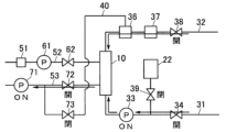
図1に示すように、血液浄化装置1は、患者Cの血液を浄化するダイアライザ10と、ダイアライザ10を介して患者Cの血液を循環させる体外循環ユニット11と、ダイアライザ10に接続され、ダイアライザ10に透析液を供給すると共に、ダイアライザ10からの排液を排出する透析液回路41を有した透析液給排ユニット12と、を備えている。体外循環ユニット11と透析液給排ユニット12とは、別体で構成されており、ダイアライザ10は、固定用治具13を介して体外循環ユニット11に着脱自在に取り付けられている。なお、ダイアライザ10は、血液浄化器の一例である。 (Configuration of blood purification device)
As shown in FIG. 1, the blood purification device 1 includes adialyzer 10 that purifies the blood of a patient C, an extracorporeal circulation unit 11 that circulates the blood of the patient C via the dialyzer 10, and a dialyzer 10 connected to the dialyzer 10. The dialyzer 10 includes a dialysate supply/drain unit 12 having a dialysate circuit 41 for supplying dialysate to the dialyzer 10 and discharging waste fluid from the dialyzer 10. The extracorporeal circulation unit 11 and the dialysate supply/drainage unit 12 are configured separately, and the dialyzer 10 is detachably attached to the extracorporeal circulation unit 11 via a fixing jig 13. Note that the dialyzer 10 is an example of a blood purifier.
図1に示すように、血液浄化装置1は、患者Cの血液を浄化するダイアライザ10と、ダイアライザ10を介して患者Cの血液を循環させる体外循環ユニット11と、ダイアライザ10に接続され、ダイアライザ10に透析液を供給すると共に、ダイアライザ10からの排液を排出する透析液回路41を有した透析液給排ユニット12と、を備えている。体外循環ユニット11と透析液給排ユニット12とは、別体で構成されており、ダイアライザ10は、固定用治具13を介して体外循環ユニット11に着脱自在に取り付けられている。なお、ダイアライザ10は、血液浄化器の一例である。 (Configuration of blood purification device)
As shown in FIG. 1, the blood purification device 1 includes a
ダイアライザ10は、血液浄化膜(中空糸型の血液透析膜又は血液透析濾過膜、或いは、平膜型の血液透析膜又は血液濾過膜)を内蔵している。また、ダイアライザ10は、血液を導入する血液導入口10a及び導入した血液を導出する血液導出口10bを有すると共に、透析液を導入する透析液導入口10c及び導入した透析液を排出する透析液排出口10dを有している。ダイアライザ10では、血液浄化膜を介して血液と透析液とを接触させることで、血液を浄化する。
The dialyzer 10 has a built-in blood purification membrane (a hollow fiber type hemodialysis membrane or hemodiafiltration membrane, or a flat membrane type hemodialysis membrane or hemofiltration membrane). The dialyzer 10 also has a blood inlet 10a for introducing blood and a blood outlet 10b for discharging the introduced blood, as well as a dialysate inlet 10c for introducing dialysate and a dialysate drain for discharging the introduced dialysate. It has an outlet 10d. In the dialyzer 10, blood is purified by bringing the blood into contact with a dialysate via a blood purification membrane.
体外循環ユニット11は、ダイアライザ10を介して患者Cの血液を循環させる血液回路21と、供給配管22aを介して血液回路21に接続された貯留バッグ22と、血液回路21に接続された血液回路側連通配管23と、制御部24と、を有している。貯留バッグ22は、プライミング液を貯留する貯留部の一例である。また、制御部24については、後述する。
The extracorporeal circulation unit 11 includes a blood circuit 21 that circulates the blood of the patient C through the dialyzer 10, a storage bag 22 connected to the blood circuit 21 through a supply pipe 22a, and a blood circuit connected to the blood circuit 21. It has a side communication pipe 23 and a control section 24. The storage bag 22 is an example of a storage section that stores priming liquid. Further, the control unit 24 will be described later.
血液回路21は、ダイアライザ10の血液導入口10aに接続され、患者Cの血管から採取した血液をダイアライザ10に導く動脈側血液配管31と、ダイアライザ10の血液導出口10bに接続され、ダイアライザ10から排出された血液を患者Cの血管に戻す静脈側血液配管32と、を有している。
The blood circuit 21 is connected to the blood inlet 10 a of the dialyzer 10 , is connected to an arterial blood piping 31 that leads blood collected from the blood vessel of the patient C to the dialyzer 10 , and is connected to the blood outlet 10 b of the dialyzer 10 , and is connected to the blood outlet 10 b of the dialyzer 10 . It has a venous blood piping 32 that returns the discharged blood to the patient C's blood vessel.
動脈側血液配管31には、血液ポンプ33及び動脈側クランプ34が配設されている。血液ポンプ33は、血液に圧力を付与して送液する送液ポンプであり、例えば、しごき型ポンプで構成されている。動脈側クランプ34は、血液ポンプ33の上流側に配設され、動脈側血液配管31を開閉する。
A blood pump 33 and an arterial clamp 34 are disposed on the arterial blood piping 31. The blood pump 33 is a liquid pump that applies pressure to blood and sends it, and is configured, for example, as a straining type pump. The artery side clamp 34 is arranged upstream of the blood pump 33 and opens and closes the artery side blood piping 31.
一方、静脈側血液配管32には、エアトラップチャンバ36、気泡検出器37及び静脈側クランプ38が配設されている。エアトラップチャンバ36は、血液中の気泡を捕捉するチャンバである。気泡検出器37は、血液中の気泡を検出する。静脈側クランプ38は、エアトラップチャンバ36及び気泡検出器37の下流側に配設され、静脈側血液配管32を開閉する。
On the other hand, the venous blood piping 32 is provided with an air trap chamber 36, a bubble detector 37, and a venous clamp 38. The air trap chamber 36 is a chamber that traps air bubbles in the blood. Air bubble detector 37 detects air bubbles in blood. The venous clamp 38 is disposed downstream of the air trap chamber 36 and the bubble detector 37, and opens and closes the venous blood piping 32.
血液回路21では、動脈側クランプ34及び静脈側クランプ38を開放した状態で、血液ポンプ33を駆動することで、患者Cからの血液が、動脈側血液配管31を介してダイアライザ10に導かれ、ダイアライザ10によって浄化された後、静脈側血液配管32を介して患者Cに戻される。これにより、患者Cの血液が浄化される。
In the blood circuit 21, blood from the patient C is guided to the dialyzer 10 via the arterial blood piping 31 by driving the blood pump 33 with the arterial clamp 34 and the venous clamp 38 open. After being purified by dialyzer 10, it is returned to patient C via venous blood piping 32. This purifies patient C's blood.
貯留バッグ22は、供給配管22aを介して、動脈側血液配管31における血液ポンプ33と動脈側クランプ34との間に接続されている。貯留バッグ22は、プライミング液としての生理食塩水を貯留しており、プライミングの際には、貯留バッグ22に収容された生理食塩水を、供給配管22aを介して血液回路21に充填する。また、供給配管22aには、供給配管22aを開閉する供給側クランプ39が配設されている。
The storage bag 22 is connected between the blood pump 33 and the artery clamp 34 in the artery blood pipe 31 via the supply pipe 22a. The storage bag 22 stores physiological saline as a priming solution, and during priming, the physiological saline contained in the storage bag 22 is filled into the blood circuit 21 via the supply piping 22a. Further, a supply side clamp 39 that opens and closes the supply pipe 22a is disposed on the supply pipe 22a.
血液回路側連通配管23は、エアトラップチャンバ36に接続されている。血液回路側連通配管23は、排液ポートPを介して、後述の透析液回路側連通配管42に接続され、透析液回路側連通配管42と共に、血液回路21と透析液回路41(の後述の排液排出流路53)とを連通する連通流路40を構成する。
The blood circuit side communication pipe 23 is connected to the air trap chamber 36. The blood circuit side communication pipe 23 is connected to the dialysate circuit side communication pipe 42 (described later) via the drainage port P, and together with the dialysate circuit side communication pipe 42, the blood circuit 21 and the dialysate circuit 41 (described later) are connected to the dialysate circuit side communication pipe 42 (described later). A communication channel 40 is configured to communicate with the drain liquid discharge channel 53).
透析液給排ユニット12は、ダイアライザ10に透析液を供給すると共にダイアライザ10からの排液を排出する透析液回路41と、透析液回路41に接続された透析液回路側連通配管42と、透析液給排ユニット側制御部43と、を有している。
The dialysate supply/drain unit 12 includes a dialysate circuit 41 that supplies dialysate to the dialyzer 10 and discharges waste fluid from the dialyzer 10, a dialysate circuit side communication piping 42 connected to the dialysate circuit 41, and It has a liquid supply/discharge unit side control section 43.
透析液回路41は、透析液を精製する透析液調製部51と、ダイアライザ10の透析液導入口10cに接続され、透析液調製部51で精製された透析液をダイアライザ10に供給する透析液供給流路52と、ダイアライザ10の透析液排出口10dに接続され、ダイアライザ10からの排液を回収し排出する排液排出流路53と、を有している。
The dialysate circuit 41 is connected to a dialysate preparation section 51 that purifies the dialysate and to the dialysate inlet 10c of the dialyzer 10, and serves as a dialysate supply circuit for supplying the dialysate purified by the dialysate preparation section 51 to the dialyzer 10. It has a flow path 52 and a drain discharge flow path 53 that is connected to the dialysate discharge port 10d of the dialyzer 10 and collects and discharges the drain fluid from the dialyzer 10.
透析液調製部51は、供給された純水と、濃縮液又は粉末からなる透析剤とから、透析液を調製する。透析液調製部51に供給される純水は、透析液給排ユニット12に搭載された純水製造部から供給される構成であってもよいし、透析液給排ユニット12の外部に設けられた純水製造装置から供給される構成であってもよい。なお、透析液調製部51も省略可能であり、例えば、外部の透析液供給装置等から、透析液給排ユニット12に透析液が供給されるよう構成してもよい。
The dialysate preparation unit 51 prepares a dialysate from the supplied pure water and a dialysate made of a concentrated liquid or powder. The pure water supplied to the dialysate preparation unit 51 may be supplied from a pure water production unit installed in the dialysate supply and discharge unit 12, or may be provided outside the dialysate supply and discharge unit 12. Alternatively, the water may be supplied from a pure water production apparatus. Note that the dialysate preparation section 51 can also be omitted, and, for example, the dialysate may be configured to be supplied to the dialysate supply and discharge unit 12 from an external dialysate supply device or the like.
透析液供給流路52には、給液ポンプ61及び第1電磁弁62が配設されている。給液ポンプ61は、ダイアライザ10に供給する圧力を透析液に付与して、透析液を送液する送液ポンプであり、例えば、ダイアフラムポンプで構成されている。給液ポンプ61を駆動することで、透析液をダイアライザ10に供給する。第1電磁弁62は、給液ポンプ61の下流側に配設され、透析液供給流路52を開閉する。
A fluid supply pump 61 and a first electromagnetic valve 62 are disposed in the dialysate supply channel 52. The liquid supply pump 61 is a liquid supply pump that applies pressure to the dialysate to supply the dialysate and sends the dialysate, and is configured, for example, as a diaphragm pump. By driving the fluid supply pump 61, dialysate is supplied to the dialyzer 10. The first electromagnetic valve 62 is disposed downstream of the fluid supply pump 61 and opens and closes the dialysate supply channel 52 .
排液排出流路53には、排液ポンプ71及び第2電磁弁72が配設されている。排液ポンプ71は、給液ポンプ61に対して別体且つ独立駆動可能に構成され、ダイアライザ10から排出する圧力を排液に付与して、排液を送液する送液ポンプであり、例えば、ダイアフラムポンプで構成されている。排液ポンプ71を駆動することで、ダイアライザ10からの排液を排出する。第2電磁弁72は、排液ポンプ71の上流側に配設され、排液排出流路53を開閉する。
A drain pump 71 and a second electromagnetic valve 72 are disposed in the drain drain channel 53. The drain pump 71 is configured to be able to be driven separately and independently from the liquid supply pump 61, and is a liquid feeding pump that applies pressure to the drained liquid to discharge it from the dialyzer 10 and sends the drained liquid, for example. , consists of a diaphragm pump. By driving the drain pump 71, the drain liquid from the dialyzer 10 is discharged. The second electromagnetic valve 72 is disposed upstream of the drain pump 71 and opens and closes the drain drain passage 53 .
透析液回路側連通配管42は、排液排出流路53における排液ポンプ71と第2電磁弁72との間に接続されている。透析液回路側連通配管42は、排液ポートPを介して、血液回路側連通配管23に接続され、血液回路側連通配管23と共に、ダイアライザ10を迂回して血液回路21と排液排出流路53とを連通する連通流路40を構成する。すなわち、連通流路40は、一端が、静脈側血液配管32におけるエアトラップチャンバ36に接続され、他端が、排液排出流路53における排液ポンプ71の上流側に接続されている。また、透析液回路側連通配管42には、連通流路40を開閉する第3電磁弁73が配設されている。プライミングの際には、第2電磁弁72を閉塞すると共に第3電磁弁73を開放した状態で、排液ポンプ71を駆動することで、排液ポンプ71の上流側に接続された連通流路40を介して、血液回路21を吸引する。なお、第2電磁弁72は、排出側開閉弁の一例であり、第3電磁弁73は、開閉弁の一例である。
The dialysate circuit side communication pipe 42 is connected between the drain pump 71 and the second electromagnetic valve 72 in the drain drain channel 53. The dialysate circuit side communication pipe 42 is connected to the blood circuit side communication pipe 23 via the drainage port P, and together with the blood circuit side communication pipe 23, it bypasses the dialyzer 10 and connects to the blood circuit 21 and the drain fluid discharge channel. A communication channel 40 is configured to communicate with 53. That is, one end of the communication channel 40 is connected to the air trap chamber 36 in the venous blood piping 32, and the other end is connected to the upstream side of the drain pump 71 in the drain discharge channel 53. Further, a third solenoid valve 73 that opens and closes the communication channel 40 is disposed in the dialysate circuit side communication pipe 42 . During priming, by driving the drain pump 71 with the second solenoid valve 72 closed and the third solenoid valve 73 open, the communication channel connected to the upstream side of the drain pump 71 is activated. Through 40, the blood circuit 21 is aspirated. Note that the second solenoid valve 72 is an example of a discharge side on-off valve, and the third solenoid valve 73 is an example of an on-off valve.
透析液給排ユニット側制御部43は、体外循環ユニット11の制御部24と通信を行い、制御部24の指令に従って、給液ポンプ61、排液ポンプ71及び各電磁弁62、72、73を制御する。透析液給排ユニット側制御部43は、CPU等の演算素子、メモリ、ソフトウェア、インターフェイス、通信ユニット等を適宜組み合わせて実現される。
The dialysate supply/drainage unit side control section 43 communicates with the control section 24 of the extracorporeal circulation unit 11, and operates the fluid supply pump 61, drainage pump 71, and each electromagnetic valve 62, 72, 73 according to instructions from the control section 24. Control. The dialysate supply/discharge unit side control section 43 is realized by appropriately combining an arithmetic element such as a CPU, memory, software, an interface, a communication unit, etc.
(制御部及びその制御の説明)
ここで、制御部24及び当該制御部24による制御について説明する。制御部24は、CPU等の演算素子、メモリ、ソフトウェア、インターフェイス、通信ユニット等を適宜組み合わせて実現されるものであり、気泡検出器37の検出値を受け付けると共に、血液ポンプ33及び各クランプ34、38、39を制御する。また、制御部24は、透析液給排ユニット側制御部43と通信を行い、透析液給排ユニット側制御部43を介して、給液ポンプ61、排液ポンプ71及び各電磁弁62、72、73を制御する。 (Explanation of control unit and its control)
Here, thecontrol section 24 and the control by the control section 24 will be explained. The control unit 24 is realized by appropriately combining an arithmetic element such as a CPU, memory, software, an interface, a communication unit, etc., and receives the detected value of the bubble detector 37, and also receives the detected value of the blood pump 33 and each clamp 34, 38 and 39 are controlled. The control unit 24 also communicates with the dialysate supply/drainage unit side control unit 43 , and communicates with the dialysate supply/drainage unit side control unit 43 via the dialysate supply/drainage unit side control unit 43 . , 73.
ここで、制御部24及び当該制御部24による制御について説明する。制御部24は、CPU等の演算素子、メモリ、ソフトウェア、インターフェイス、通信ユニット等を適宜組み合わせて実現されるものであり、気泡検出器37の検出値を受け付けると共に、血液ポンプ33及び各クランプ34、38、39を制御する。また、制御部24は、透析液給排ユニット側制御部43と通信を行い、透析液給排ユニット側制御部43を介して、給液ポンプ61、排液ポンプ71及び各電磁弁62、72、73を制御する。 (Explanation of control unit and its control)
Here, the
制御部24は、血液ポンプ33、給液ポンプ61及び排液ポンプ71を制御して、透析治療動作を実行する。透析治療動作では、血液ポンプ33を駆動して、ダイアライザ10を介して血液を循環すると共に、給液ポンプ61を駆動して、ダイアライザ10に透析液を供給し、排液ポンプ71を駆動して、ダイアライザ10からの排液を排出する。これによって、患者Cの血液がダイアライザ10を介して循環されつつ、ダイアライザ10に対し透析液が給排出されて、患者Cの血液が浄化される。
The control unit 24 controls the blood pump 33, fluid supply pump 61, and drainage pump 71 to execute the dialysis treatment operation. In the dialysis treatment operation, the blood pump 33 is driven to circulate blood through the dialyzer 10, the fluid supply pump 61 is driven to supply dialysate to the dialyzer 10, and the drain pump 71 is driven. , drain the effluent from the dialyzer 10. As a result, patient C's blood is circulated through dialyzer 10 while dialysate is supplied to and discharged from dialyzer 10, thereby purifying patient C's blood.
また、制御部24は、血液ポンプ33、排液ポンプ71、各電磁弁62、72、73及び各クランプ34、38、39を制御して、プライミング動作及び置換液排出動作を実行する。ここで図2A乃至図5を参照して、プライミング動作及び置換液排出動作について説明する。
Further, the control unit 24 controls the blood pump 33, the drain pump 71, each electromagnetic valve 62, 72, 73, and each clamp 34, 38, 39 to execute a priming operation and a substituent liquid discharge operation. Here, the priming operation and the substituent liquid discharge operation will be described with reference to FIGS. 2A to 5.
(プライミング動作の説明)
プライミング動作は、血液透析動作の前に、血液回路21内に生理食塩水を充填する動作である。また、プライミング動作は、図2A乃至図2Cに示すように、動脈側血液配管31及び静脈側血液配管32の先端同士をカプラ81によって連結し連通した状態で行われる。また、プライミング動作は、第2電磁弁72を閉塞し、動脈側クランプ34及び静脈側クランプ38を開放した状態で行われる。制御部24が、プライミング動作を実行する。 (Explanation of priming operation)
The priming operation is an operation of filling theblood circuit 21 with physiological saline before the hemodialysis operation. Further, the priming operation is performed with the distal ends of the arterial blood piping 31 and the venous blood piping 32 connected and communicating with each other by a coupler 81, as shown in FIGS. 2A to 2C. Further, the priming operation is performed with the second solenoid valve 72 closed and the arterial clamp 34 and the venous clamp 38 open. The control unit 24 executes a priming operation.
プライミング動作は、血液透析動作の前に、血液回路21内に生理食塩水を充填する動作である。また、プライミング動作は、図2A乃至図2Cに示すように、動脈側血液配管31及び静脈側血液配管32の先端同士をカプラ81によって連結し連通した状態で行われる。また、プライミング動作は、第2電磁弁72を閉塞し、動脈側クランプ34及び静脈側クランプ38を開放した状態で行われる。制御部24が、プライミング動作を実行する。 (Explanation of priming operation)
The priming operation is an operation of filling the
図2A乃至図3に示すように、プライミング動作では、まず、第3電磁弁73を閉塞し(S1)、供給側クランプ39を開放する(S2)。その後、排液ポンプ71を駆動する(S3)。すなわち、第3電磁弁73を閉塞して、血液回路21と排液排出流路53とを遮断させた状態で排液ポンプ71を駆動することで、排液ポンプ71から第2電磁弁72及び第3電磁弁73までの配管内(所定領域内)を陰圧化(血液回路21よりも圧力を低く)し蓄圧する(図2A参照)。これにより、第3電磁弁73を開放したとき、排液排出流路53内の排液が血液回路21に逆流しないようにする。なお、排液ポンプ71から第2電磁弁72及び第3電磁弁73までの配管内が陰圧化したか否かの判定は、例えば、排液ポンプ71から第2電磁弁72及び第3電磁弁73までの配管に設けた圧力検出部の検出値によって行う。なお、当該圧力検出部は、例えば、排液排出流路53における排液ポンプ71と第2電磁弁72との間に設けられ、血液浄化治療で透析液圧を検出(監視)する透析液圧センサを兼用してもよく、これに代えて、任意のセンサを他用途との兼用又は専用で用いることも可能である。
As shown in FIGS. 2A to 3, in the priming operation, first, the third solenoid valve 73 is closed (S1), and the supply side clamp 39 is opened (S2). After that, the drain pump 71 is driven (S3). That is, by closing the third electromagnetic valve 73 and driving the drain pump 71 in a state where the blood circuit 21 and the drain fluid discharge channel 53 are cut off, the drain pump 71 is able to drain the second electromagnetic valve 72 and the drain pump 71. The pressure inside the piping (within a predetermined area) up to the third electromagnetic valve 73 is reduced to negative (pressure lower than that of the blood circuit 21) and the pressure is accumulated (see FIG. 2A). Thereby, when the third electromagnetic valve 73 is opened, the drained liquid in the drained liquid discharge channel 53 is prevented from flowing back into the blood circuit 21. Note that the determination as to whether or not the inside of the piping from the drain pump 71 to the second solenoid valve 72 and the third solenoid valve 73 has become negative pressure can be made, for example, by This is done based on the detected value of a pressure detection section provided in the piping up to the valve 73. Note that the pressure detection unit is provided, for example, between the drain pump 71 and the second electromagnetic valve 72 in the drain discharge channel 53, and detects (monitors) the dialysate pressure in blood purification treatment. The sensor may also be used, or alternatively, any sensor may be used for other purposes or exclusively.
排液ポンプ71から第3電磁弁73までの配管内を陰圧化(蓄圧)したら、排液ポンプ71を駆動した状態のまま、第3電磁弁73を開放する(S4)。第3電磁弁73の開放によって、連通流路40を介して血液回路21と排液排出流路53とを送液可能に連通した状態で、排液ポンプ71を駆動する状態となる。これによって、排液ポンプ71により、連通流路40を介して血液回路21を吸引する。すなわち、S3で蓄圧した蓄圧圧力に基づき血液回路21を吸引する。排液ポンプ71により血液回路21を吸引し、血液回路21内を陰圧化することで、貯留バッグ22に貯留された生理食塩水が動脈側血液配管31に流入する。血液回路21に流入した生理食塩水は、カプラ81を経て静脈側血液配管32を通りエアトラップチャンバ36に至る。そして、エアトラップチャンバ36から連通流路40を介して排液排出流路53に流入し排液ポンプ71に到達する。これにより、動脈側血液配管31及び静脈側血液配管32における、貯留バッグ22の接続位置からエアトラップチャンバ36までの配管が充填され、またエアトラップチャンバ36にも生理食塩水が蓄積される(図2B参照)。すなわち、排液ポンプ71を駆動することで、血液回路21内の生理食塩水を排液排出流路53に吸引する。
After the inside of the pipe from the drain pump 71 to the third solenoid valve 73 is made negative pressure (pressure is accumulated), the third solenoid valve 73 is opened while the drain pump 71 remains driven (S4). By opening the third electromagnetic valve 73, the drain pump 71 is driven with the blood circuit 21 and the drain discharge channel 53 communicating with each other via the communication channel 40 so as to be able to send liquid. As a result, the blood circuit 21 is sucked by the drain pump 71 through the communication channel 40 . That is, the blood circuit 21 is sucked based on the accumulated pressure accumulated in S3. By suctioning the blood circuit 21 by the drain pump 71 and making the inside of the blood circuit 21 negative pressure, the physiological saline stored in the storage bag 22 flows into the arterial blood piping 31. The physiological saline that has flowed into the blood circuit 21 passes through the coupler 81, the venous blood piping 32, and reaches the air trap chamber 36. Then, the liquid flows from the air trap chamber 36 through the communication channel 40 into the drain discharge channel 53 and reaches the drain pump 71 . As a result, the arterial blood piping 31 and the venous blood piping 32 from the connection position of the storage bag 22 to the air trap chamber 36 are filled, and physiological saline is also accumulated in the air trap chamber 36 (Fig. (See 2B). That is, by driving the drain pump 71, physiological saline in the blood circuit 21 is sucked into the drain drain channel 53.
第3電磁弁73の開放から一定時間経過して、貯留バッグ22の接続位置からエアトラップチャンバ36までの流路に生理食塩水が充填されたら、第3電磁弁73を閉塞し(S5)、排液ポンプ71を停止する(S6)。その後、供給側クランプ39を閉塞して(S7)、血液ポンプ33を駆動(逆転駆動)する(S8)。血液ポンプ33の駆動によって、血液回路21内で生理食塩水が流動し、エアトラップチャンバ36で空気が一部捕捉されつつ、生理食塩水が血液回路21内で循環する(図2C参照)。なお、図2Cの例では、血液ポンプ33を逆転駆動する構成としたが、血液ポンプ33を正転駆動する構成であってもよい。
When a certain period of time has elapsed since the opening of the third solenoid valve 73 and the flow path from the connection position of the storage bag 22 to the air trap chamber 36 is filled with saline, the third solenoid valve 73 is closed (S5); The drain pump 71 is stopped (S6). Thereafter, the supply side clamp 39 is closed (S7), and the blood pump 33 is driven (reversely driven) (S8). Physiological saline flows within the blood circuit 21 by driving the blood pump 33, and the physiological saline circulates within the blood circuit 21 while some air is trapped in the air trap chamber 36 (see FIG. 2C). In the example of FIG. 2C, the blood pump 33 is driven in reverse, but the blood pump 33 may be driven in normal rotation.
生理食塩水を一定時間循環させたら、気泡検出器37によって、血液回路21内を流動する空気量を検出する(S9)。検出の結果、血液回路21内を流動する空気量が一定値未満ではないと判定された場合(S9:No)、S2に戻り、S2からS8までの一連の動作を繰返し行う。これによって、徐々に血液回路21内に生理食塩水を充填していき、血液回路21内の空気量を減少させていく。そして、血液回路21内に空気がなくなり、血液回路21内を流動する空気量が一定値未満であると判定された場合(S9:Yes)、本プライミング動作を終了する。これにより、血液回路21内に生理食塩水を充填し、血液回路21内をプライミングする。なお、貯留バッグ22から生理食塩水を吸引したとき(S4)、エアトラップチャンバ36にも生理食塩水が蓄積されるため、1回の吸引で血液回路21内に溜まる生理食塩水の量が多くなり、上記一連の動作(S2~S8)の繰返し回数を少なくすることができる。
After the physiological saline is circulated for a certain period of time, the air bubble detector 37 detects the amount of air flowing in the blood circuit 21 (S9). As a result of the detection, if it is determined that the amount of air flowing in the blood circuit 21 is not less than a certain value (S9: No), the process returns to S2 and repeats the series of operations from S2 to S8. As a result, the blood circuit 21 is gradually filled with physiological saline, and the amount of air in the blood circuit 21 is reduced. Then, if it is determined that there is no air in the blood circuit 21 and the amount of air flowing in the blood circuit 21 is less than a certain value (S9: Yes), the main priming operation is ended. This fills the blood circuit 21 with physiological saline and primes the blood circuit 21. Note that when saline is sucked from the storage bag 22 (S4), the saline is also accumulated in the air trap chamber 36, so a large amount of saline accumulates in the blood circuit 21 with one suction. Therefore, the number of repetitions of the series of operations (S2 to S8) can be reduced.
(置換液排出動作の説明)
置換液排出動作は、血液浄化装置1が血液治療後に血液回路21に置換液(例えば、生理食塩水)を充填することで血液回路21内に残留する血液を患者Cに返血した後に、当該返血に際して血液回路21に充填された置換液を排出する動作である。また、置換液排出動作は、図4A及び図4Bに示すように、動脈側血液配管31及び静脈側血液配管32の先端を患者Cから取り外して空気開放した状態で行われる。また、置換液排出動作は、第3電磁弁73及び供給側クランプ39を閉塞した状態で行われる。制御部24が、置換液排出動作を実行する。 (Explanation of replacement liquid discharge operation)
The substitution fluid discharge operation is performed after the blood purification device 1 returns the blood remaining in theblood circuit 21 to the patient C by filling the blood circuit 21 with a substitution fluid (for example, physiological saline) after blood treatment. This is an operation for discharging the replacement fluid filled in the blood circuit 21 during blood return. Further, the substituent fluid discharge operation is performed with the tips of the arterial blood piping 31 and the venous blood piping 32 removed from the patient C to release air, as shown in FIGS. 4A and 4B. Further, the replacement liquid discharge operation is performed with the third solenoid valve 73 and the supply side clamp 39 closed. The control unit 24 executes a substituent liquid discharge operation.
置換液排出動作は、血液浄化装置1が血液治療後に血液回路21に置換液(例えば、生理食塩水)を充填することで血液回路21内に残留する血液を患者Cに返血した後に、当該返血に際して血液回路21に充填された置換液を排出する動作である。また、置換液排出動作は、図4A及び図4Bに示すように、動脈側血液配管31及び静脈側血液配管32の先端を患者Cから取り外して空気開放した状態で行われる。また、置換液排出動作は、第3電磁弁73及び供給側クランプ39を閉塞した状態で行われる。制御部24が、置換液排出動作を実行する。 (Explanation of replacement liquid discharge operation)
The substitution fluid discharge operation is performed after the blood purification device 1 returns the blood remaining in the
図4A乃至図5に示すように、置換液排出動作では、まず、動脈側クランプ34及び静脈側クランプ38を閉塞し(S11)、第2電磁弁72を閉塞する(S12)。その後、排液ポンプ71を駆動する(S13)(図4A参照)。すなわち、第2電磁弁72を閉塞した状態で排液ポンプ71を駆動することで、排液ポンプ71から第2電磁弁72及び第3電磁弁73までの配管内(所定領域内)を陰圧化(血液回路21よりも圧力を低く)し、蓄圧する。これにより、第2電磁弁72を開放したとき、排液排出流路53内の排液が血液回路21に逆流しないようにする。なお、排液ポンプ71から第2電磁弁72及び第3電磁弁73までの配管内が陰圧化したか否かの判定は、例えば、排液ポンプ71から第2電磁弁72及び第3電磁弁73までの配管に設けた圧力検出部の検出値によって行う。なお、当該圧力検出部は、例えば、排液排出流路53における排液ポンプ71と第2電磁弁72との間に設けられ、血液浄化治療で透析液圧を検出(監視)する透析液圧センサを兼用してもよく、これに代えて、任意のセンサを他用途との兼用又は専用で用いることも可能である。
As shown in FIGS. 4A to 5, in the substituent fluid discharge operation, first, the arterial side clamp 34 and the venous side clamp 38 are occluded (S11), and the second electromagnetic valve 72 is occluded (S12). After that, the drain pump 71 is driven (S13) (see FIG. 4A). That is, by driving the drain pump 71 with the second solenoid valve 72 closed, negative pressure is created in the piping (within a predetermined area) from the drain pump 71 to the second solenoid valve 72 and the third solenoid valve 73. (lower pressure than the blood circuit 21) and accumulate pressure. Thereby, when the second electromagnetic valve 72 is opened, the drained liquid in the drained liquid discharge channel 53 is prevented from flowing back into the blood circuit 21. Note that the determination as to whether or not the inside of the piping from the drain pump 71 to the second solenoid valve 72 and the third solenoid valve 73 has become negative pressure can be made, for example, by This is done based on the detected value of a pressure detection section provided in the piping up to the valve 73. Note that the pressure detection unit is provided, for example, between the drain pump 71 and the second electromagnetic valve 72 in the drain discharge channel 53, and detects (monitors) the dialysate pressure in blood purification treatment. The sensor may also be used, or alternatively, any sensor may be used for other purposes or exclusively.
排液ポンプ71から第2電磁弁72までの配管内を陰圧化したら、第2電磁弁72を開放し(S14)、動脈側クランプ34及び静脈側クランプ38を開放して(S15)、血液ポンプ33を駆動する(S16)。第2電磁弁72の開放及び血液ポンプ33の駆動によって、ダイアライザ10を介して血液回路21と排液排出流路53とを送液可能に連通した状態で、排液ポンプ71及び血液ポンプ33を駆動する状態となる。これにより、排液ポンプ71によって、ダイアライザ10を介して血液回路21内の置換液を排液排出流路53に吸引する。すなわち、S13で蓄圧した蓄圧圧力に基づき血液回路21内の置換液を排液排出流路53に吸引する。具体的には、排液ポンプ71及び血液ポンプ33の駆動によって、排液ポンプ71の圧力で、静脈側血液配管32に空気が導入されながら静脈側血液配管32内の置換液がダイアライザ10を介して排液排出流路53に流入し排出されると共に、血液ポンプ33の圧力で、動脈側血液配管31に空気が導入されながら動脈側血液配管31内の置換液がダイアライザ10を介して排液排出流路53に流入し排出される(図4B参照)。これにより、血液回路21内の置換液が排液排出流路53を介して排出される。なお、排液ポンプ71の流量と血液ポンプ33の流量とが同等であると、動脈側血液配管31内の置換液のみ排出され、静脈側血液配管32内の置換液が排出されない現象が生じる。そのため、血液ポンプ33の目標流量に対し、排液ポンプ71の目標流量を、静脈側血液配管32内の置換液を排出する流量分だけ多くする。
Once the pressure inside the piping from the drainage pump 71 to the second solenoid valve 72 has been reduced to negative, the second solenoid valve 72 is opened (S14), the arterial side clamp 34 and the venous side clamp 38 are opened (S15), and the blood is drained. The pump 33 is driven (S16). By opening the second electromagnetic valve 72 and driving the blood pump 33, the drain pump 71 and the blood pump 33 are opened in a state where the blood circuit 21 and the drain drain passage 53 are communicated with each other via the dialyzer 10 so that the liquid can be sent. It will be in a driving state. As a result, the drainage pump 71 sucks the replacement fluid in the blood circuit 21 into the drainage channel 53 via the dialyzer 10 . That is, the replacement fluid in the blood circuit 21 is sucked into the drain fluid discharge channel 53 based on the accumulated pressure accumulated in S13. Specifically, by driving the drain pump 71 and the blood pump 33, air is introduced into the venous blood piping 32 by the pressure of the drain pump 71, and the replacement liquid in the venous blood piping 32 is passed through the dialyzer 10. At the same time, the replacement fluid in the arterial blood piping 31 is drained through the dialyzer 10 while air is introduced into the arterial blood piping 31 by the pressure of the blood pump 33. It flows into the discharge channel 53 and is discharged (see FIG. 4B). As a result, the replacement fluid in the blood circuit 21 is discharged via the drain fluid discharge channel 53. Note that if the flow rate of the drain pump 71 and the flow rate of the blood pump 33 are equal, a phenomenon occurs in which only the replacement fluid in the arterial blood piping 31 is discharged and the replacement fluid in the venous blood piping 32 is not discharged. Therefore, the target flow rate of the drain pump 71 is increased by the flow rate for discharging the replacement fluid in the venous blood piping 32 relative to the target flow rate of the blood pump 33.
置換液を排出が終了したら、血液ポンプ33を停止し(S17)、第2電磁弁72を閉塞して(S18)、排液ポンプ71を停止する(S19)。これにより、本置換液排出動作を終了する。
Once the replacement fluid has been discharged, the blood pump 33 is stopped (S17), the second electromagnetic valve 72 is closed (S18), and the drain pump 71 is stopped (S19). This completes the substituent liquid discharging operation.
(実施形態の作用及び効果)
以上、上記実施形態の構成によれば、プライミングや置換液排出における血液回路21の吸引を、排液ポンプ71を用いて行う構成であるため、簡単な構成で且つプライミングや置換液の排出を迅速に行うことができる。すなわち、ダイアライザ10から排出する圧力を排液に付与する排液ポンプ71を、給液ポンプ61に対し独立駆動可能とし、この排液ポンプ71を血液回路21の吸引に利用することで、高い圧力で血液回路21を吸引することができる。これにより、プライミングや置換液排出をより迅速に(例えば、除水ポンプを用いる場合の約30倍程度の速度で)行うことができると共に、別途高圧力のポンプを設ける必要がなく、血液浄化装置1を簡単な構成にすることができる。 (Actions and effects of embodiments)
As described above, according to the configuration of the above embodiment, the suction of theblood circuit 21 during priming and replacement fluid discharge is performed using the drainage pump 71, so the configuration is simple and the priming and replacement fluid discharge can be performed quickly. can be done. That is, the drain pump 71 that applies pressure to the drain fluid to be discharged from the dialyzer 10 can be driven independently of the fluid supply pump 61, and by using this drain pump 71 for suction into the blood circuit 21, high pressure can be achieved. The blood circuit 21 can be suctioned. As a result, priming and replacement fluid discharge can be performed more quickly (for example, approximately 30 times faster than when using a water removal pump), and there is no need to provide a separate high-pressure pump. 1 can be made into a simple configuration.
以上、上記実施形態の構成によれば、プライミングや置換液排出における血液回路21の吸引を、排液ポンプ71を用いて行う構成であるため、簡単な構成で且つプライミングや置換液の排出を迅速に行うことができる。すなわち、ダイアライザ10から排出する圧力を排液に付与する排液ポンプ71を、給液ポンプ61に対し独立駆動可能とし、この排液ポンプ71を血液回路21の吸引に利用することで、高い圧力で血液回路21を吸引することができる。これにより、プライミングや置換液排出をより迅速に(例えば、除水ポンプを用いる場合の約30倍程度の速度で)行うことができると共に、別途高圧力のポンプを設ける必要がなく、血液浄化装置1を簡単な構成にすることができる。 (Actions and effects of embodiments)
As described above, according to the configuration of the above embodiment, the suction of the
(変形例)
以上、本発明の実施形態を説明したが、上記した実施形態は特許請求の範囲に係る発明を限定するものではない。また、実施形態の中で説明した特徴の組合せの全てが発明の課題を解決するための手段に必須であるとは限らない点に留意すべきである。 (Modified example)
Although the embodiments of the present invention have been described above, the embodiments described above do not limit the invention according to the claims. Furthermore, it should be noted that not all combinations of features described in the embodiments are essential for solving the problems of the invention.
例えば、図6に示すように、排液排出流路53における排液ポンプ71の上流側に配設され、排液中の気泡を除去する気泡捕獲器101(気泡除去部の一例)を更に備え、連通流路40(透析液回路側連通配管42)の透析液回路41側を気泡捕獲器101に接続する構成であってもよい。かかる場合、気泡捕獲器101は、例えば、排液中の気泡を検出する気泡検知センサ101aと、脱ガスチャンバ101bとを含んで構成されている。そして、例えば、透析液回路41が、排液排出流路53に接続され、排液ポンプ71を迂回して液体を排出する排出流路102を更に有し、気泡検知センサ101aによって脱ガスチャンバ101b内の空気量を検出し、脱ガスチャンバ101b内の空気量が所定量以上になったとき、排出流路102で脱ガスチャンバ101b内の空気を排出する構成とする。かかる構成によれば、プライミング動作時に、排液ポンプ71に空気が入るのを防止することができる。これにより、排液ポンプ71において、エア噛みにより吐出力が低下するのを防止することができる。すなわち、当該構成によって、エア噛みにより吐出力が低下する小型の排液ポンプ71を利用することができ、排液ポンプ71を小型化することができる。また、排液排出流路53における排液ポンプ71の上流側に配設された気泡捕獲器101をプライミング動作時のエア抜きにも利用するため、透析治療動作時の排液のエア抜きと、プライミング動作時の排液のエア抜きとを、単一の気泡捕獲器101で行うことができ、血液浄化装置1を簡単な構成にすることができる。
For example, as shown in FIG. 6, it further includes an air bubble catcher 101 (an example of an air bubble removal section) that is disposed upstream of the drainage pump 71 in the drainage channel 53 and removes air bubbles from the drainage. , the dialysate circuit 41 side of the communication channel 40 (dialysate circuit side communication piping 42) may be connected to the bubble trap 101. In such a case, the bubble trap 101 is configured to include, for example, a bubble detection sensor 101a that detects bubbles in the drained liquid and a degassing chamber 101b. For example, the dialysate circuit 41 further includes a discharge channel 102 that is connected to the drain fluid discharge channel 53 and discharges the fluid bypassing the drain pump 71, and is activated by the bubble detection sensor 101a into the degassing chamber 101b. The air amount in the degassing chamber 101b is detected, and when the amount of air in the degassing chamber 101b exceeds a predetermined amount, the air in the degassing chamber 101b is discharged through the exhaust flow path 102. According to this configuration, it is possible to prevent air from entering the drain pump 71 during the priming operation. Thereby, in the drain pump 71, it is possible to prevent the discharge force from decreasing due to air trapping. That is, with this configuration, it is possible to use a small-sized drain pump 71 whose discharge force is reduced due to air trapping, and the drain pump 71 can be downsized. In addition, since the bubble trap 101 disposed upstream of the drainage pump 71 in the drainage channel 53 is also used to bleed air during the priming operation, it can be used to bleed air from the effluent during the dialysis treatment operation. Air removal from the drained fluid during the priming operation can be performed using a single bubble trap 101, and the blood purification device 1 can be configured simply.
また、図6に記載の構成では、排液排出流路53における排液ポンプ71の上流側に気泡検知センサ101aを配設したことで、置換液排出動作時においても、排液ポンプ71内に空気が入り込むのを防止することができる。さらに、図6に記載の構成において、血液回路21内の置換液を排液排出流路53に排出する場合(置換液排出動作における置換液排出時)、気泡検知センサ101aによって置換液中の気泡を検知したとき、排出流路102で置換液を排出することで、置換液排出動作時において、排液ポンプ71に空気を入れることなく、置換液を排出することができる。
In addition, in the configuration shown in FIG. 6, by disposing the bubble detection sensor 101a on the upstream side of the drain pump 71 in the drain drain channel 53, even during the displacement liquid discharge operation, there is no air inside the drain pump 71. Air can be prevented from entering. Furthermore, in the configuration shown in FIG. 6, when discharging the replacement fluid in the blood circuit 21 to the drain fluid discharge channel 53 (during the displacement fluid discharge in the displacement fluid discharge operation), the air bubble detection sensor 101a detects air bubbles in the replacement fluid. By discharging the substitution liquid through the discharge channel 102 when this is detected, the substitution liquid can be discharged without introducing air into the drainage pump 71 during the substitution liquid discharge operation.
また、上記実施形態においては、置換液排出動作における置換液の排出を、ダイアライザ10を介して行う構成であったが、これに限るものではない。すなわち、置換液排出動作における置換液の排出を、第2電磁弁72を閉塞しつつ第3電磁弁73を開放し、連通流路40を介して血液回路21と排液排出流路53とを連通した状態で行う構成であってもよい。つまり、置換液排出動作における置換液の排出を、連通流路40を介して血液回路21と排液排出流路53とを連通した状態で、排液ポンプ71を駆動することで行う構成であってもよい。かかる場合には、プライミング動作と同様、第3電磁弁73を閉塞した状態で排液ポンプ71を駆動し、排液ポンプ71から第3電磁弁73までの配管内(所定領域内)を陰圧化し蓄圧した後、第3電磁弁73を開放して置換液の排出を行う。
Furthermore, in the above embodiment, the replacement liquid is discharged via the dialyzer 10 in the replacement liquid discharge operation, but the present invention is not limited to this. That is, the discharge of the replacement fluid in the replacement fluid discharge operation is performed by closing the second solenoid valve 72 and opening the third solenoid valve 73 to connect the blood circuit 21 and the drain fluid discharge channel 53 via the communication channel 40. The configuration may be such that the communication is performed. In other words, the configuration is such that the replacement fluid is discharged in the replacement fluid discharge operation by driving the drainage pump 71 while the blood circuit 21 and the drainage fluid discharge channel 53 are in communication with each other via the communication channel 40. It's okay. In such a case, similarly to the priming operation, the drain pump 71 is driven with the third solenoid valve 73 closed, and the inside of the piping (within a predetermined area) from the drain pump 71 to the third solenoid valve 73 is brought under negative pressure. After the pressure is accumulated, the third solenoid valve 73 is opened to discharge the replacement liquid.
(実施形態のまとめ)
次に、以上説明した実施形態から把握される技術思想について、実施形態における符号等を援用して記載する。ただし、以下の記載における各符号等は、特許請求の範囲における構成要素を実施形態に具体的に示した部材等に限定するものではない。 (Summary of embodiments)
Next, technical ideas understood from the embodiments described above will be described using reference numerals and the like in the embodiments. However, each reference numeral in the following description does not limit the constituent elements in the claims to those specifically shown in the embodiments.
《1》血液浄化膜が内蔵される血液浄化器(10)を介して患者(C)の血液を浄化する血液浄化装置(1)であって、前記血液浄化器(10)を介して前記血液を循環させる血液回路(21)と、前記血液浄化器(10)に透析液を供給する透析液供給流路(52)と、前記血液浄化器(10)からの排液を排出する排液排出流路(53)と、前記透析液供給流路(52)に配設され、前記血液浄化器(10)に供給する圧力を前記透析液に付与する給液ポンプ(61)と、前記排液排出流路(53)に配設されると共に、前記給液ポンプ(61)に対して別体且つ独立駆動可能に構成され、前記血液浄化器(10)から排出する圧力を前記排液に付与する排液ポンプ(71)と、を備え、前記血液浄化器(10)を迂回して前記血液回路(21)と前記排液排出流路(53)とを連通する連通流路(40)、又は前記血液浄化器(10)を介して、前記血液回路(21)と前記排液排出流路(53)とを送液可能に連通した状態で、前記排液ポンプ(71)を駆動することで、前記血液回路(21)内の液体を前記排液排出流路(53)に吸引する、血液浄化装置(1)。
これにより、簡単な構成で且つプライミングや置換液の排出を迅速に行うことができる。
《2》供給配管(22a)を介して前記血液回路(21)に接続され、プライミング液を貯留する貯留部(22)と、前記連通流路(40)と、を更に備え、前記連通流路(40)を介して前記血液回路(21)と前記排液排出流路(53)とを連通した状態で、前記排液ポンプ(71)を駆動することで、前記貯留部(22)から前記血液回路(21)内に前記プライミング液を充填し、前記血液回路(21)内をプライミングする、《1》に記載の血液浄化装置(1)。
これにより、簡単な構成で且つプライミングを迅速に行うことができる。
《3》前記排液排出流路(53)における前記排液ポンプ(71)の上流側に配設され、前記排液中の気泡を除去する気泡除去部(101)を、更に備え、前記連通流路(40)は、前記気泡除去部(101)に接続されている、《1》又は《2》に記載の血液浄化装置(1)。
これにより、排液ポンプに空気が入るのを防止することができる。
《4》前記連通流路(40)には、前記連通流路(40)を開閉する開閉弁(73)が配設され、前記開閉弁(73)を閉塞して前記血液回路(21)と前記排液排出流路(53)とを遮断させた状態で、前記排液ポンプ(71)を駆動して前記排液排出流路(53)及び前記連通流路(40)の所定領域内を蓄圧した後、前記開閉弁(73)を開放することによって、蓄圧圧力に基づき前記血液回路(21)内の液体を前記排液排出流路(53)に吸引する、《1》又は《2》に記載の血液浄化装置(1)。
これにより、排液排出流路内の排液が血液回路に逆流するのを防止することができる。
《5》血液浄化治療後に、前記血液回路(21)に置換液を充填することで前記血液回路(21)内に残留する血液を患者(C)に返血し、前記血液浄化器(10)を介して前記血液回路(21)と前記排液排出流路(53)とを連通した状態で、前記排液ポンプ(71)を駆動することで、前記血液回路(21)に空気を導入しながら前記置換液を前記排液排出流路(53)に排出する、《1》乃至《3》のいずれか1つに記載の血液浄化装置(1)。
これにより、簡単な構成で且つ置換液の排出を迅速に行うことができる。
《6》前記排液排出流路(53)における前記排液ポンプ(71)の上流側には、前記排液排出流路(53)を開閉する排出側開閉弁(72)が配設され、前記排出側開閉弁(72)を閉塞した状態で、前記排液ポンプ(71)を駆動して前記排液排出流路(53)の所定領域内を蓄圧した後、前記排出側開閉弁(72)を開放することによって、蓄圧圧力に基づき前記血液回路(21)内の液体を前記排液排出流路(53)に吸引する、《5》に記載の血液浄化装置(1)。
これにより、排液排出流路内の排液が血液回路に逆流するのを防止することができる。
《7》前記排液排出流路(53)における前記排液ポンプ(71)の上流側に配設され、前記排液中の気泡を検知する気泡検知センサ(101a)を、更に備えた、《5》又は《6》に記載の血液浄化装置(1)。
これにより、排液ポンプに空気が入るのを防止することができる。
《8》前記排液排出流路(53)に接続され、前記排液ポンプ(71)を迂回して液体を排出する排出流路(102)を、更に備え、前記血液回路(21)内の前記置換液を前記排液排出流路(53)に排出する場合、前記気泡検知センサ(101a)によって前記置換液中の気泡を検知したとき、前記排出流路(102)から前記置換液を排出する、《7》に記載の血液浄化装置(1)。
これにより、置換液排出動作時において、排液ポンプに空気を入れることなく、置換液を排出することができる。 <<1>> A blood purification device (1) that purifies the blood of a patient (C) through a blood purifier (10) having a built-in blood purification membrane, the blood purification device (1) purifying the blood of a patient (C) through the blood purifier (10). a blood circuit (21) for circulating blood, a dialysate supply flow path (52) for supplying dialysate to the blood purifier (10), and a waste fluid discharge for discharging the waste fluid from the blood purifier (10). a flow path (53), a fluid supply pump (61) that is disposed in the dialysate supply flow path (52) and applies pressure to the dialysate to supply the blood purifier (10), and the drain fluid. It is arranged in the discharge flow path (53) and is configured to be able to be driven separately and independently from the liquid supply pump (61), and applies pressure to the drained liquid to be discharged from the blood purifier (10). a drain pump (71), which communicates the blood circuit (21) and the drain discharge channel (53) by bypassing the blood purifier (10); or driving the drain pump (71) in a state where the blood circuit (21) and the drain drain channel (53) are in fluid communication with each other via the blood purifier (10). and a blood purification device (1) that sucks the liquid in the blood circuit (21) into the waste liquid discharge channel (53).
Thereby, priming and discharging of the replacement liquid can be performed quickly with a simple configuration.
<<2>> Further comprising: a storage section (22) that is connected to the blood circuit (21) via a supply pipe (22a) and stores a priming liquid; and the communication channel (40); By driving the drain pump (71) with the blood circuit (21) and the drain drain channel (53) communicating with each other via the drain tube (40), The blood purification device (1) according to <<1>>, wherein the blood circuit (21) is filled with the priming liquid to prime the blood circuit (21).
Thereby, priming can be performed quickly with a simple configuration.
<<3>> Further comprising an air bubble removal section (101) disposed upstream of the drainage pump (71) in the drainage fluid discharge channel (53) to remove air bubbles in the drainage fluid, The blood purification device (1) according to <<1>> or <<2>>, wherein the flow path (40) is connected to the bubble removing section (101).
This can prevent air from entering the drain pump.
<<4>> The communication flow path (40) is provided with an on-off valve (73) that opens and closes the communication flow path (40), and closes the on-off valve (73) to connect to the blood circuit (21). With the drain discharge channel (53) cut off, the drain pump (71) is driven to move within a predetermined area of the drain discharge channel (53) and the communication channel (40). <<1>> or <<2>>, in which the liquid in the blood circuit (21) is sucked into the drain discharge channel (53) based on the accumulated pressure by opening the on-off valve (73) after accumulating the pressure; Blood purification device (1) according to.
Thereby, it is possible to prevent the drained liquid in the drained liquid discharge channel from flowing back into the blood circuit.
<<5>> After the blood purification treatment, the blood remaining in the blood circuit (21) is returned to the patient (C) by filling the blood circuit (21) with a replacement fluid, and the blood purifier (10) Air is introduced into the blood circuit (21) by driving the drain pump (71) with the blood circuit (21) and the drain drain channel (53) communicating with each other via the drain pump (71). The blood purification device (1) according to any one of <<1>> to <<3>>, wherein the replacement liquid is discharged into the waste liquid discharge channel (53).
Thereby, the replacement liquid can be discharged quickly with a simple configuration.
<<6>> A discharge side opening/closing valve (72) for opening and closing the waste liquid discharge passage (53) is disposed upstream of the liquid discharge pump (71) in the waste liquid discharge passage (53), With the discharge side on-off valve (72) closed, the drain pump (71) is driven to accumulate pressure in a predetermined area of the drain discharge channel (53), and then the discharge side on-off valve (72) is closed. ) The blood purification device (1) according to <5>, wherein the liquid in the blood circuit (21) is sucked into the waste liquid discharge channel (53) based on the accumulated pressure by opening the blood purification device (1).
Thereby, it is possible to prevent the drained liquid in the drained liquid discharge channel from flowing back into the blood circuit.
<<7>> Further comprising a bubble detection sensor (101a) disposed on the upstream side of the drain pump (71) in the drain liquid discharge channel (53) to detect air bubbles in the drain liquid; The blood purification device (1) according to item 5 or item 6.
This can prevent air from entering the drain pump.
<<8>> Further comprising a drain channel (102) connected to the drain fluid drain channel (53) and for discharging the liquid bypassing the drain pump (71), In the case of discharging the replacement liquid to the drain liquid discharge channel (53), when the bubble detection sensor (101a) detects air bubbles in the substitute liquid, the substitute liquid is discharged from the discharge channel (102). The blood purification device (1) according to <7>.
Thereby, during the substituent liquid discharge operation, the substituent liquid can be discharged without introducing air into the drain pump.
1:血液浄化装置、 10:ダイアライザ、 21:血液回路、 22:貯留バッグ、 22a:供給配管、 40:連通流路、 52:透析液供給流路、 53:排液排出流路、 61:給液ポンプ、 71:排液ポンプ、 72:第2電磁弁、 73:第3電磁弁、 101:気泡捕獲器、 101a:気泡検知センサ、 102:排出流路、 C:患者
1: Blood purification device, 10: Dialyzer, 21: Blood circuit, 22: Storage bag, 22a: Supply piping, 40: Communication channel, 52: Dialysate supply channel, 53: Drain discharge channel, 61: Supply Liquid pump, 71: Drain pump, 72: Second solenoid valve, 73: Third solenoid valve, 101: Bubble catcher, 101a: Bubble detection sensor, 102: Drain channel, C: Patient
Claims (8)
- 血液浄化膜が内蔵される血液浄化器を介して患者の血液を浄化する血液浄化装置であって、
前記血液浄化器を介して前記血液を循環させる血液回路と、
前記血液浄化器に透析液を供給する透析液供給流路と、
前記血液浄化器からの排液を排出する排液排出流路と、
前記透析液供給流路に配設され、前記血液浄化器に供給する圧力を前記透析液に付与する給液ポンプと、
前記排液排出流路に配設されると共に、前記給液ポンプに対して別体且つ独立駆動可能に構成され、前記血液浄化器から排出する圧力を前記排液に付与する排液ポンプと、を備え、
前記血液浄化器を迂回して前記血液回路と前記排液排出流路とを連通する連通流路、又は前記血液浄化器を介して、前記血液回路と前記排液排出流路とを送液可能に連通した状態で、前記排液ポンプを駆動することで、前記血液回路内の液体を前記排液排出流路に吸引する、
血液浄化装置。 A blood purification device that purifies a patient's blood through a blood purifier having a built-in blood purification membrane,
a blood circuit that circulates the blood through the blood purifier;
a dialysate supply channel that supplies dialysate to the blood purifier;
a drainage channel for discharging the drainage from the blood purifier;
a fluid supply pump that is disposed in the dialysate supply flow path and applies pressure to the dialysate to be supplied to the blood purifier;
a drain pump that is disposed in the drain discharge flow path, is configured to be able to be driven separately and independently from the liquid supply pump, and applies pressure to the drain fluid to be discharged from the blood purifier; Equipped with
Liquid can be sent between the blood circuit and the waste fluid discharge channel through a communication channel that communicates the blood circuit and the waste fluid discharge channel by bypassing the blood purifier, or via the blood purifier. Driving the drainage pump in a state where the fluid is in communication with the blood circuit draws the liquid in the blood circuit into the drainage drainage channel;
Blood purification device. - 供給配管を介して前記血液回路に接続され、プライミング液を貯留する貯留部と、
前記連通流路と、を更に備え、
前記連通流路を介して前記血液回路と前記排液排出流路とを連通した状態で、前記排液ポンプを駆動することで、前記貯留部から前記血液回路内に前記プライミング液を充填し、前記血液回路内をプライミングする、
請求項1に記載の血液浄化装置。 a storage section connected to the blood circuit via a supply piping and storing a priming liquid;
further comprising the communication flow path,
filling the blood circuit with the priming liquid from the reservoir by driving the drain pump while the blood circuit and the drain discharge channel are in communication with each other via the communication channel; priming within the blood circuit;
The blood purification device according to claim 1. - 前記排液排出流路における前記排液ポンプの上流側に配設され、前記排液中の気泡を除去する気泡除去部を、更に備え、
前記連通流路は、前記気泡除去部に接続されている、
請求項1又は2に記載の血液浄化装置。 further comprising an air bubble removal unit disposed upstream of the drainage pump in the drainage discharge flow path and for removing air bubbles in the drainage;
the communication flow path is connected to the bubble removal section,
The blood purification device according to claim 1 or 2. - 前記連通流路には、前記連通流路を開閉する開閉弁が配設され、
前記開閉弁を閉塞して前記血液回路と前記排液排出流路とを遮断させた状態で、前記排液ポンプを駆動して前記排液排出流路及び前記連通流路の所定領域内を蓄圧した後、前記開閉弁を開放することによって、蓄圧圧力に基づき前記血液回路内の液体を前記排液排出流路に吸引する、
請求項1又は2に記載の血液浄化装置。 The communication flow path is provided with an on-off valve that opens and closes the communication flow path,
With the opening/closing valve closed to block the blood circuit and the drainage drainage channel, the drainage pump is driven to accumulate pressure in a predetermined area of the drainage drainage channel and the communication channel. After that, by opening the on-off valve, the liquid in the blood circuit is sucked into the drain discharge channel based on the accumulated pressure.
The blood purification device according to claim 1 or 2. - 血液浄化治療後に、前記血液回路に置換液を充填することで前記血液回路内に残留する血液を患者に返血し、
前記血液浄化器を介して前記血液回路と前記排液排出流路とを連通した状態で、前記排液ポンプを駆動することで、前記血液回路に空気を導入しながら前記置換液を前記排液排出流路に排出する、
請求項1に記載の血液浄化装置。 After the blood purification treatment, the blood remaining in the blood circuit is returned to the patient by filling the blood circuit with a replacement fluid,
By driving the drainage pump with the blood circuit and the wastewater discharge passage communicating with each other via the blood purifier, the replacement liquid is introduced into the wastewater while introducing air into the blood circuit. discharge into the discharge channel,
The blood purification device according to claim 1. - 前記排液排出流路における前記排液ポンプの上流側には、前記排液排出流路を開閉する排出側開閉弁が配設され、
前記排出側開閉弁を閉塞した状態で、前記排液ポンプを駆動して前記排液排出流路の所定領域内を蓄圧した後、前記排出側開閉弁を開放することによって、蓄圧圧力に基づき前記血液回路内の液体を前記排液排出流路に吸引する、
請求項5に記載の血液浄化装置。 A discharge-side opening/closing valve that opens and closes the drain discharge channel is disposed upstream of the drain pump in the drain discharge channel,
With the discharge side on-off valve closed, the drain pump is driven to accumulate pressure in a predetermined area of the waste liquid discharge channel, and then the discharge side on-off valve is opened to increase the pressure based on the accumulated pressure. aspirating the liquid in the blood circuit into the drainage channel;
The blood purification device according to claim 5. - 前記排液排出流路における前記排液ポンプの上流側に配設され、前記排液中の気泡を検知する気泡検知センサを、更に備えた、
請求項5又は6に記載の血液浄化装置。 further comprising an air bubble detection sensor disposed upstream of the drainage pump in the drainage discharge flow path and detecting air bubbles in the drainage;
The blood purification device according to claim 5 or 6. - 前記排液排出流路に接続され、前記排液ポンプを迂回して液体を排出する排出流路を、更に備え、
前記血液回路内の前記置換液を前記排液排出流路に排出する場合、前記気泡検知センサによって前記置換液中の気泡を検知したとき、前記排出流路で前記置換液を排出する、
請求項7に記載の血液浄化装置。
further comprising a discharge channel connected to the drain fluid discharge channel and configured to bypass the drain pump and discharge the liquid;
When discharging the replacement fluid in the blood circuit to the waste fluid discharge channel, when the bubble detection sensor detects air bubbles in the substitution fluid, discharging the replacement fluid in the discharge channel;
The blood purification device according to claim 7.
Applications Claiming Priority (2)
| Application Number | Priority Date | Filing Date | Title |
|---|---|---|---|
| JP2022103784A JP2024004226A (en) | 2022-06-28 | 2022-06-28 | blood purification device |
| JP2022-103784 | 2022-06-28 |
Publications (1)
| Publication Number | Publication Date |
|---|---|
| WO2024004483A1 true WO2024004483A1 (en) | 2024-01-04 |
Family
ID=89382664
Family Applications (1)
| Application Number | Title | Priority Date | Filing Date |
|---|---|---|---|
| PCT/JP2023/019910 WO2024004483A1 (en) | 2022-06-28 | 2023-05-29 | Blood purification device |
Country Status (2)
| Country | Link |
|---|---|
| JP (1) | JP2024004226A (en) |
| WO (1) | WO2024004483A1 (en) |
Citations (6)
| Publication number | Priority date | Publication date | Assignee | Title |
|---|---|---|---|---|
| JP2003199820A (en) * | 2001-12-28 | 2003-07-15 | Nikkiso Co Ltd | Dialyzing equipment and priming, fluid replacing and blood recovering method therefor |
| JP2013102927A (en) * | 2011-11-14 | 2013-05-30 | Nikkiso Co Ltd | Blood purification device |
| JP2017077383A (en) * | 2015-10-21 | 2017-04-27 | 日機装株式会社 | Blood purification device |
| JP2020103709A (en) * | 2018-12-28 | 2020-07-09 | 日機装株式会社 | Blood purifying device |
| US20210322662A1 (en) * | 2018-07-11 | 2021-10-21 | Fresenius Medical Care Deutschland Gmbh | A Control And/Or Closed-Loop Control Device For Removing Fluid from A Blood Filter |
| JP2022078501A (en) * | 2020-11-13 | 2022-05-25 | 日機装株式会社 | Blood purifying apparatus |
-
2022
- 2022-06-28 JP JP2022103784A patent/JP2024004226A/en active Pending
-
2023
- 2023-05-29 WO PCT/JP2023/019910 patent/WO2024004483A1/en unknown
Patent Citations (6)
| Publication number | Priority date | Publication date | Assignee | Title |
|---|---|---|---|---|
| JP2003199820A (en) * | 2001-12-28 | 2003-07-15 | Nikkiso Co Ltd | Dialyzing equipment and priming, fluid replacing and blood recovering method therefor |
| JP2013102927A (en) * | 2011-11-14 | 2013-05-30 | Nikkiso Co Ltd | Blood purification device |
| JP2017077383A (en) * | 2015-10-21 | 2017-04-27 | 日機装株式会社 | Blood purification device |
| US20210322662A1 (en) * | 2018-07-11 | 2021-10-21 | Fresenius Medical Care Deutschland Gmbh | A Control And/Or Closed-Loop Control Device For Removing Fluid from A Blood Filter |
| JP2020103709A (en) * | 2018-12-28 | 2020-07-09 | 日機装株式会社 | Blood purifying device |
| JP2022078501A (en) * | 2020-11-13 | 2022-05-25 | 日機装株式会社 | Blood purifying apparatus |
Also Published As
| Publication number | Publication date |
|---|---|
| JP2024004226A (en) | 2024-01-16 |
Similar Documents
| Publication | Publication Date | Title |
|---|---|---|
| JP6685374B2 (en) | Blood purification device and priming method thereof | |
| AU2007350967B2 (en) | Method and apparatus for priming an extracorporeal blood circuit. | |
| JP2004313522A (en) | Dialyzer | |
| US8998837B2 (en) | Apparatus for extracorporeal blood treatment | |
| JP5707190B2 (en) | Blood purification equipment | |
| US20120298580A1 (en) | Method for rinsing and/or for filling a blood treatment device and blood treatment device | |
| EP3777917A1 (en) | Blood purification apparatus and method for capturing bubbles therein | |
| JP2011160963A (en) | Dialyzer | |
| CN107405440B (en) | Blood purification device | |
| US11554202B2 (en) | Blood purification apparatus and method of discharging bubbles therefrom | |
| WO2024004483A1 (en) | Blood purification device | |
| JP5431228B2 (en) | Blood purification equipment | |
| JP6266695B2 (en) | Blood purification apparatus and priming method thereof | |
| US20210213189A1 (en) | Blood purification apparatus | |
| JP6566687B2 (en) | Blood purification apparatus, priming method and operating method of blood purification apparatus | |
| JP6671159B2 (en) | Blood purification device | |
| JP7249147B2 (en) | blood purifier | |
| US11964089B2 (en) | Blood purification apparatus and method of trapping bubbles therein | |
| JP7293761B2 (en) | Determining method for dialysis machine and circuit set | |
| JP6488048B2 (en) | Blood purification equipment | |
| WO2023032960A1 (en) | Blood purification device | |
| JP7114466B2 (en) | Blood purification device and priming method | |
| JP6357496B2 (en) | Blood purification equipment | |
| JPH06134031A (en) | Blood dialyzing and filtering device | |
| TW202206129A (en) | A filter device for dialysis applications |
Legal Events
| Date | Code | Title | Description |
|---|---|---|---|
| 121 | Ep: the epo has been informed by wipo that ep was designated in this application |
Ref document number: 23830933 Country of ref document: EP Kind code of ref document: A1 |