WO2024004306A1 - 制御装置、システム、制御方法、プログラム - Google Patents
制御装置、システム、制御方法、プログラム Download PDFInfo
- Publication number
- WO2024004306A1 WO2024004306A1 PCT/JP2023/013780 JP2023013780W WO2024004306A1 WO 2024004306 A1 WO2024004306 A1 WO 2024004306A1 JP 2023013780 W JP2023013780 W JP 2023013780W WO 2024004306 A1 WO2024004306 A1 WO 2024004306A1
- Authority
- WO
- WIPO (PCT)
- Prior art keywords
- range
- user
- display
- real space
- control device
- Prior art date
- Legal status (The legal status is an assumption and is not a legal conclusion. Google has not performed a legal analysis and makes no representation as to the accuracy of the status listed.)
- Ceased
Links
Images


Classifications
-
- G—PHYSICS
- G06—COMPUTING OR CALCULATING; COUNTING
- G06V—IMAGE OR VIDEO RECOGNITION OR UNDERSTANDING
- G06V10/00—Arrangements for image or video recognition or understanding
- G06V10/70—Arrangements for image or video recognition or understanding using pattern recognition or machine learning
- G06V10/77—Processing image or video features in feature spaces; using data integration or data reduction, e.g. principal component analysis [PCA] or independent component analysis [ICA] or self-organising maps [SOM]; Blind source separation
- G06V10/776—Validation; Performance evaluation
-
- G—PHYSICS
- G06—COMPUTING OR CALCULATING; COUNTING
- G06F—ELECTRIC DIGITAL DATA PROCESSING
- G06F3/00—Input arrangements for transferring data to be processed into a form capable of being handled by the computer; Output arrangements for transferring data from processing unit to output unit, e.g. interface arrangements
- G06F3/01—Input arrangements or combined input and output arrangements for interaction between user and computer
- G06F3/03—Arrangements for converting the position or the displacement of a member into a coded form
- G06F3/033—Pointing devices displaced or positioned by the user, e.g. mice, trackballs, pens or joysticks; Accessories therefor
- G06F3/0346—Pointing devices displaced or positioned by the user, e.g. mice, trackballs, pens or joysticks; Accessories therefor with detection of the device orientation or free movement in a 3D space, e.g. 3D mice, 6-DOF [six degrees of freedom] pointers using gyroscopes, accelerometers or tilt-sensors
-
- G—PHYSICS
- G06—COMPUTING OR CALCULATING; COUNTING
- G06F—ELECTRIC DIGITAL DATA PROCESSING
- G06F3/00—Input arrangements for transferring data to be processed into a form capable of being handled by the computer; Output arrangements for transferring data from processing unit to output unit, e.g. interface arrangements
- G06F3/01—Input arrangements or combined input and output arrangements for interaction between user and computer
- G06F3/048—Interaction techniques based on graphical user interfaces [GUI]
- G06F3/0481—Interaction techniques based on graphical user interfaces [GUI] based on specific properties of the displayed interaction object or a metaphor-based environment, e.g. interaction with desktop elements like windows or icons, or assisted by a cursor's changing behaviour or appearance
- G06F3/04815—Interaction with a metaphor-based environment or interaction object displayed as three-dimensional, e.g. changing the user viewpoint with respect to the environment or object
-
- G—PHYSICS
- G06—COMPUTING OR CALCULATING; COUNTING
- G06T—IMAGE DATA PROCESSING OR GENERATION, IN GENERAL
- G06T11/00—2D [Two Dimensional] image generation
-
- G—PHYSICS
- G06—COMPUTING OR CALCULATING; COUNTING
- G06T—IMAGE DATA PROCESSING OR GENERATION, IN GENERAL
- G06T19/00—Manipulating 3D models or images for computer graphics
-
- G—PHYSICS
- G06—COMPUTING OR CALCULATING; COUNTING
- G06T—IMAGE DATA PROCESSING OR GENERATION, IN GENERAL
- G06T7/00—Image analysis
- G06T7/50—Depth or shape recovery
-
- G—PHYSICS
- G06—COMPUTING OR CALCULATING; COUNTING
- G06T—IMAGE DATA PROCESSING OR GENERATION, IN GENERAL
- G06T7/00—Image analysis
- G06T7/70—Determining position or orientation of objects or cameras
-
- G—PHYSICS
- G06—COMPUTING OR CALCULATING; COUNTING
- G06V—IMAGE OR VIDEO RECOGNITION OR UNDERSTANDING
- G06V20/00—Scenes; Scene-specific elements
- G06V20/20—Scenes; Scene-specific elements in augmented reality scenes
-
- G—PHYSICS
- G06—COMPUTING OR CALCULATING; COUNTING
- G06T—IMAGE DATA PROCESSING OR GENERATION, IN GENERAL
- G06T2207/00—Indexing scheme for image analysis or image enhancement
- G06T2207/30—Subject of image; Context of image processing
- G06T2207/30196—Human being; Person
Definitions
- the present invention relates to a control device, a system, a control method, and a program.
- the same virtual object may be displayed on the head-mounted displays (HMDs) of multiple users located in different real spaces.
- a virtual person (avatar) arranged according to the user's position in the second real space may be displayed on the HMD worn by the user located in the first real space.
- the size of the first real space and the size of the second real space are different, restrictions will arise in the placement of the avatar in the HMD.
- Patent Document 1 discloses a technique that, when a virtual object is placed in a position where it should not be placed, notifies the user that the virtual object has been placed in a position where it should not be placed.
- Patent Document 1 after the virtual object is placed at a position where it should not be placed, it is notified that the virtual object has been placed at a position where it should not be placed. Therefore, the user cannot know in advance that there is a possibility that the virtual object will be placed in a position where it should not be placed.
- an object of the present invention is to provide a technology that makes it possible to grasp the possibility that a virtual object will be placed in an inappropriate position when placing the virtual object according to the user's position.
- One aspect of the present invention is a control device that controls a display device worn by a first user in a first real space, wherein the first control means for controlling the display device to display a virtual object placed at a position in the first real space, and a range display object indicating a movable range of the virtual object in the first real space; It is a control device characterized by having.
- One aspect of the present invention is a control method for controlling a display device worn by a first user in a first real space, wherein the first display device corresponds to a position of the second user in a second real space.
- the present invention when arranging a virtual object according to the user's position, it is possible to grasp the possibility that the virtual object will be placed at an inappropriate position.
- FIG. 1 is a diagram illustrating a system according to a first embodiment.
- FIG. 2A is a diagram illustrating a usage image of the system according to the first embodiment.
- FIG. 2B is a diagram showing a display example of the HMD according to the first embodiment.
- FIG. 2C is a diagram showing a composite image generated by the camera according to the first embodiment.
- FIG. 3A is a diagram illustrating an example of a real space according to the first embodiment.
- FIG. 3B is a diagram illustrating problems related to the first embodiment.
- 4A and 4B are diagrams illustrating the movable range of the avatar according to the first embodiment.
- FIG. 5 is a configuration diagram of a video see-through type HMD according to the first embodiment.
- FIG. 5 is a configuration diagram of a video see-through type HMD according to the first embodiment.
- FIG. 6 is a configuration diagram of an optical see-through type HMD according to the first embodiment.
- FIG. 7 is a configuration diagram of a camera according to the first embodiment.
- FIG. 8 is a diagram illustrating the user's position according to the first embodiment.
- FIG. 9 is a flowchart showing range information detection processing according to the first embodiment.
- FIG. 10 is a diagram showing a list regarding obstacle objects according to the first embodiment.
- FIG. 11 is a diagram illustrating the effective range according to the first embodiment.
- 12A and 12B are diagrams illustrating gradation display of the effective range according to the first embodiment.
- FIG. 13 is a diagram illustrating range information according to the first embodiment.
- FIG. 14 is a diagram illustrating a system according to the second embodiment.
- HMD head mounted display
- Technologies such as AR or MR are used in HMDs, smartphones, tablet terminals, and the like.
- an HMD that can be worn on a user's head has a display placed in front of the user's eyes. Therefore, the HMD can display useful information according to the usage scene and can provide the user with a deep sense of immersion.
- HMDs There are two types of HMDs: optical see-through HMDs that use transparent (semi-transparent) displays and video see-through HMDs that use opaque displays.
- an optical see-through type HMD a user can simultaneously view both an image and incident light from the outside world.
- the user can see the external space through the display.
- an optical see-through type HMD for example, a user can experience an event (such as a concert or sports day) at a certain place through the HMD, and read various information about the person or thing the user is paying attention to on the HMD. You can get it from the display.
- a video see-through type HMD can display a virtual space on a display in front of the user's eyes, or display an image acquired by a camera mounted on the HMD on the display.
- the HMD can display various information superimposed on an image of the real space in which the user is located.
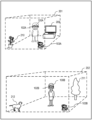
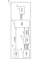
- FIG. 1 is a diagram illustrating a system 1 (display system; control system) according to the first embodiment.
- two real spaces 101 101A, 101B
- two real spaces 101 101A, 101B
- two users 100 100 (100A, 100B) are located.
- the system 1 includes an HMD 102A and a camera 103B in a real space 101A.
- System 1 includes HMD 102B and camera 103B in real space 101B.
- HMD 102A and HMD 102B have the same configuration, and camera 103A and camera 103B have the same configuration. Therefore, in the following, the content explained for one of HMD 102A and HMD 102B will not be explained for the other in principle. Similarly, the content explained for one of the cameras 103A and 103B will not be explained for the other in principle.
- the HMD 102A is an HMD worn by the user 100A (user located in the real space 101A). The description will be made assuming that the HMD 102A is a video see-through type HMD unless otherwise specified.
- the camera 103A is an imaging device installed at a fixed position in the real space 101A.
- the camera 103A images the real space 101A and the user 100A in the real space 101A.
- the camera 103A detects the position, posture, and facial expression (smiling expression, angry expression, no expression, etc.) of the user 100A from the captured image (captured image) of the user 100A (real space 101A). To detect. Then, the camera 103A transmits information on the detection results (the position, posture, and facial expression of the user 100A) to the server 107 as the status information 10A.
- the status information 10A is transmitted to the HMD 102B via the server 107. Then, the HMD 102B controls the avatar (position, posture, facial expression, etc. of the avatar) displayed on the display (display unit) according to the received status information 10A. Thereby, the user 100B wearing the HMD 102B can recognize changes in the position, posture, and facial expression of the user 100A (the other user) in real time.
- the camera 103A detects range information 20A indicating a range (effective range) in which the user 100A is movable and detectable from the captured image in the real space 101A. Then, the camera 103A transmits the range information 20A to the HMD 102B via the server 107. In this case, the HMD 102B displays the range in which the avatar can move on the display based on the received range information 20A. Details of the status information 10 (10A, 10B) and range information 20 (20A, 20B) will be described later.
- FIG. 2A shows two users 100 (100A, 100B) using HMDs 102 (102A, 102B) in different real spaces 101 (room 201, which is real space 101A, and garden 202, which is real space 101B). It shows the situation.
- the camera 103A is placed in the corner of the room 201.
- Camera 103B is placed at a corner of garden 202.
- a television 209 and a houseplant 210 are arranged in the room 201.
- a garden tree 211 and a dog 212 are placed in the garden 202.
- the effective range of the user 100A is the range excluding the range where the television 209 and the houseplant 210 are placed from the room 201, and the range in which the camera 103A can detect the user 100A.
- the effective range of the user 100B is the range excluding the range where the garden tree 211 and the dog 212 are placed from the garden 202, and the range in which the camera 103B can detect the user 100B.
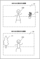
- FIG. 2B shows an example of an image displayed on the HMD 102 (102A, 102B) of the user 100 (100A, 100B).
- An avatar 220B of the user 100B is displayed on the HMD 102A with the room 201 in the background.
- an avatar 220A of the user 100A is displayed on the HMD 102B with the garden 202 in the background.
- the position, posture, facial expression, etc. of the avatar displayed on the HMD 102 change in conjunction with changes in the status of other users (users different from the user wearing the HMD 102).
- the avatar 220B is arranged so that the relative position of the user 100B with respect to the camera 103B matches the relative position of the avatar 220B with respect to the camera 103A.
- the avatar 220A is arranged such that the relative position of the user 100A with respect to the camera 103A matches the relative position of the avatar 220A with respect to the camera 103B.
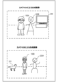
- FIG. 2C shows an example of an image in which an avatar is synthesized with an image (captured image) captured by the camera 103 (camera 103A, camera 103B) of the real space 101.
- the camera 103 (103A, camera 103B) images only the user and the background.
- the camera 103 generates a composite image in which the user and the avatar appear to be in the same real space by combining an avatar (an avatar generated based on other users' status information) and a captured image.
- the composite image generated in this way is recorded on the server 107 or distributed to an external device via the server 107. This allows the user and a third party other than the user to view a composite image in which the user and the avatar appear to be playing together.
- the composite image generated by the camera 103 will be referred to as a "camera composite image.”
- the avatar 220B is arranged so that the relative position of the user 100B with respect to the camera 103B matches the relative position of the avatar 220B with respect to the camera 103A.
- avatar 220A is arranged so that the relative position of user 100A with respect to camera 103A matches the relative position of avatar 220A with respect to camera 103B.
- the image displayed on the HMD 102 and the camera composite image may look unnatural.
- the image displayed on the HMD 102A of the user 100A the avatar 220B of the user 100B is placed outside the room 201 of the user 100A, as shown in FIG. 3B.
- the avatar 220B of the user 100B is placed outside the room 201, as shown in FIG. 3B.
- the user 100B is unable to grasp the situation in the room 201 of the user 100A. Therefore, the user 100B does not notice that the arrangement of the avatar 220B is unnatural in the image displayed on the HMD 102A and the camera composite image generated by the camera 103A. In other words, unless the user 100B knows the details of the room 201 by actually looking at the room 201, the user 100B cannot grasp the range within which the avatar 220B will not be placed in an unnatural position (the range in which the user is allowed to move). .
- an HMD 102 that displays the range in which the avatar 220B can move as the range in which the user 100A is allowed to move, based on the range information 20B in the real space 101B.
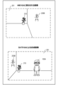
- FIG. 4A and 4B show examples of display of the range in which the avatar displayed on the HMD 102 can move.
- a virtual object hereinafter referred to as a "range display object” 401 is displayed on the HMD 102A, which shows the movable range of the user's 100B's avatar 220B using a gradation display (shaded display).
- a range display object 403 is displayed on the HMD 102B, which shows the range in which the user 100A's avatar 220A can move using a gradation display.
- the range display object 403 has transparency, and the user 100B can see the real space 101B (an image of the real space 101B) through the range display object 403.
- the user 100A recognizes a range display object 401 as shown in FIG. 4A from the display of the HMD 102A, and acts within the range of the real space 101A shown by the gradation display.
- This makes it possible to avoid placing the avatar 220A in an unnatural position in the image displayed on the HMD 102B and the composite image composited by the camera 103B.
- the range of the range display object 401 corresponds to the effective range of the user 100B, if the user 100A moves within the range of the range display object 401, the avatar 220A moves only within the effective range of the user 100B. I come to do it.
- the HMD 102 is a video see-through type HMD.
- the HMD 102 may be either an optical see-through type HMD or a video see-through type HMD.
- each configuration of the HMD 102 is controlled by a control unit (not shown). That is, the control unit controls the entire HMD 102 (display device).
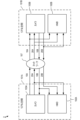
- the HMD 500 includes an imaging section 501, an acquisition section 502, an object generation section 503, a superimposition section 504, and a display section 505.
- the HMD 500 is the HMD 102A worn by the user 100A.
- the imaging unit 501 is an imaging device (camera) that captures an image of the front (front) of the user 100A (hereinafter referred to as a "front image").
- the imaging unit 501 generally uses an imaging device having an imaging angle of view (from a wide angle to a standard imaging angle) close to the field of view of the user 100A.
- the acquisition unit 502 acquires the status information 10B and range information 20B from the camera 103B of the user 100B via the server 107.
- the acquisition unit 502 transmits the state information 10B and range information 20B to the object generation unit 503.
- the position of the user 100B indicated by the status information 10B is the relative position of the user 100B with respect to the camera 103B.
- the range information 20B is information that indicates the effective range of the user 100B (the range in which the user 100B can move in the real space 101B and the range in which the camera 103B can detect the user 100B) based on the relative position from the camera 103B. Furthermore, the range information 20B includes information on the gradation level (density) of each position in the effective range, depending on the detection accuracy of the state of the user 100B at that position.
- the object generation unit 503 generates the avatar 220B (image of the avatar 220B) based on the state information 10B received from the acquisition unit 502. Further, the object generation unit 503 generates a range display object (an image of the range display object) indicating the range in which the avatar 220B can move, based on the range information 20B received from the acquisition unit 502. Specifically, the object generation unit 503 generates a range display object that can cover the range of the front image (real space 101A) that corresponds to the effective range indicated by the range information 20B. Furthermore, the object generation unit 503 colors each position of the range display object according to the gradation level of the position of the effective range corresponding to the position.
- the superimposing unit 504 creates a composite image (FIGS. 4A and 4B) in which the avatar 220B (image of the avatar 220B) and the range display object (image of the range display object) are superimposed on the image captured by the imaging unit 501 (front image). reference). Then, the superimposing unit 504 outputs the composite image to the display unit 505.
- the superimposing unit 504 places the avatar 220B at a position (position in the front image) according to the position of the user 100B indicated by the status information 10B. Specifically, the superimposing unit 504 arranges the avatar 220B so that the relative position of the user 100B with respect to the camera 103B matches the relative position of the avatar 220B with respect to the camera 103A. For this reason, for example, the superimposing unit 504 acquires in advance the relative position of the camera 103A with respect to the HMD 500, and arranges the avatar 220B based on the relative position and the state information 10B.
- the display unit 505 is a display installed in front of the user's eyes. Display unit 505 displays the composite image.
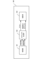
- the HMD 600 includes an acquisition section 601, an object generation section 602, and a projection section 603. In the following description, it is assumed that the HMD 600 is the HMD 102A worn by the user 100A.
- the HMD 600 does not include the imaging unit 501.
- the acquisition unit 601 acquires the status information 10B and range information 20B from the camera 103B of the user 100B via the server 107.
- the object generation unit 602 generates an avatar 220B (an image of the avatar 220B) and a range display object, similarly to the video see-through type HMD 500.
- the projection unit 603 projects the avatar 220B and the range display object onto an optical element (such as a prism) installed within the display. At this time, the projection unit 603 projects (places) the avatar 220B at a position (position on the display) according to the position of the user 100B indicated by the status information 10B. Thereby, the user can see (recognize) the space in which the avatar 220B and the range display object are arranged in the real space 101A.
- an optical element such as a prism
- the shape of the HMD 102 may be any shape such as a goggle shape, a glasses shape, and a contact lens shape.
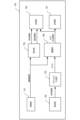
- the imaging unit 701 images the user 100A in the real space 101A.
- the imaging unit 701 is capable of imaging a wide range of the real space 101A, for example.
- the detection unit 702 detects the user 100A in the real space 101A based on the image (captured image) captured by the imaging unit 701 of the user 100A. The detection unit 702 then acquires information about the user 100A (status information 10A and range information 20A) based on the captured image. Note that, instead of acquiring the range information 20A based on the captured image, the detection unit 702 may, for example, acquire the range information 20A acquired during the previous use of the camera 103A from the recording unit 707 or the like.
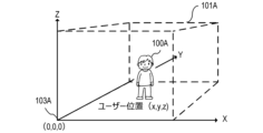
- the status information 10A is information regarding the status of the user 100A (position, posture, facial orientation, facial expression, etc.). As shown in FIG. 8, the position of the user 100A is expressed by the coordinate position where the user 100A is detected in a coordinate space whose origin is the position of the camera 103A placed in the real space 101A. Ru.
- the posture of the user 100A is estimated using a technique such as Deep Learning based on the coordinate positions of the user's limbs in the coordinate space shown in FIG.
- the direction of the face is detected based on whether the user 100A's face is facing up, down, left, or right, with the state in which the face of the user 100A is facing the camera 103A being defined as a "front-facing state.”
- the facial expression is estimated from the detection results of the degree of eye opening and the position of the corners of the mouth of the user 100A. While the imaging unit 701 is imaging the user 100A, the detection unit 702 detects the position, posture, face direction, and facial expression of the user 100A at a constant rate (period), and Update the status information 10A.
- the range information 20A is information indicating the effective range of the user 100A (the range in which the user 100A can move in the real space 101A and the range in which the camera 103A can detect the user 100A). The method for detecting the range information 20A will be described later using the flowchart of FIG.
- the transmitter 703 transmits the status information 10A and range information 20A to the server 107.
- the transmitter 703 is a communication device. Further, the transmitting unit 703 transmits the camera composite image generated by the superimposing unit 706 to the server 107.
- the acquisition unit 704 acquires the status information 10B of the user 100B via the server 107.
- the acquisition unit 704 is a communication device.
- the object generation unit 705 generates an avatar 220B (image of the avatar 220B) whose position, posture, facial expression, etc. are controlled based on the state information 10B.
- the superimposing unit 706 superimposes the avatar 220B on the captured image of the user 100A captured by the imaging unit 701 to generate a camera composite image. At this time, the superimposing unit 706 places the avatar 220B at a position (position in the captured image) according to the position of the user 100B shown in the status information 10B. Specifically, in the camera composite image, avatar 220B is arranged so that the relative position of user 100B with respect to camera 103B matches the relative position of avatar 220B with respect to camera 103A.
- the recording unit 707 stores a camera composite image (an image in which the avatar 220B is superimposed on the captured image). Further, the recording unit 707 may store the state information 10A and range information 20A acquired by the detection unit 702.
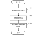
- the range information 20 detection process executed by the detection unit 702 will be described with reference to the flowchart in FIG. 9 . Below, processing executed by the detection unit 702 of the camera 103A that images the user 100A (real space 101A) will be described.
- step S901 the detection unit 702 detects an object (obstacle object) that obstructs the movement of the user 100A from the image captured by the imaging unit 701 of the user 100A (captured image).
- an object obstacle object
- the television 209 and the houseplant 210 in the room 201 correspond to the obstructing objects.
- the garden tree 211 and the dog 212 in the garden 202 correspond to the obstacle objects.
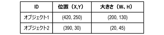
- the detection unit 702 sets a three-dimensional coordinate space whose origin is the position of the camera 103A in the real space 101A (0, 0, 0). Then, the detection unit 702 detects the position and size (width W and height H) of the obstacle object in the coordinate space.
- general recognition techniques such as AI (Artificial Intelligence) and DL (Deep Learning) may be used to improve the accuracy of detecting the obstacle object.
- the detection unit 702 indicates the position and size of each obstacle object (the vertical and horizontal lengths of the obstacle object when viewed from the Z-axis direction) as shown in FIG. 10 based on the detection results of the detected objects. Generate a list. Note that the information on the position and size of the obstacle object may be registered in advance by the user.
- step S902 the detection unit 702 detects a range (in the real space 101A) in which the user 100A can move (move without being obstructed by an obstacle object) and in which the user 100A can be detected (imaged) by the camera 103A. effective range).
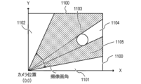
- the detection unit 702 detects a two-dimensional coordinate space (of the real space 101A viewed from the Z-axis direction in FIG. 2-dimensional coordinate space). Then, the detection unit 702 detects the camera from the boundary line 1100 of the real space 101A (the boundary line of the range in which the user 100A can move; a wall, etc.) within the range included in the imaging angle of view of the camera 103A in the set coordinate space. Find the range on the 103A side. Then, the detection unit 702 removes the object 1103 and the blind spot range 1104 (the range that cannot be seen from the camera 103A due to the presence of the object 1103) from the obtained range, and sets the range as an effective range 1105 (range indicated by diagonal lines).
- the detection unit 702 removes the object 1103 and the blind spot range 1104 (the range that cannot be seen from the camera 103A due to the presence of the object 1103) from the obtained range, and sets the range as an effective range 1105 (range indicated by diagonal lines).
- the effective range 1105 does not include the left and right blind spot ranges 1101 and 1102 that are not included in the imaging angle of view of the camera 103A.
- the blind spot range 1104 can be calculated by a known method from the position and size of each obstacle object shown in FIG. 10 (that is, the position and size of the object 1103).
- step S903 the detection unit 702 applies information regarding the detection accuracy of the state of the user 100A (position, posture, facial expression, etc. of the user 100A) within the imaging angle of view of the camera 103A to the effective range detected in step S902. to add.
- the user 100A when the effective range 1105 is detected, the user 100A can freely move inside the effective range 1105.
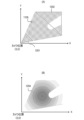
- the camera 103A in order for the camera 103A to accurately detect the state (position, posture, facial expression, etc.) of the user 100A, it is necessary to image the entire body of the user 100A at an appropriate size. For example, when capturing an image of the user 100A located in the range 1201 shown in FIG. 12A, since the user 100A is too close to the camera 103A, only a part of the body of the user 100A can be imaged. Therefore, the accuracy with which the detection unit 702 detects the state of the user 100A decreases.
- the user 100A when capturing an image of the user 100A located in the range 1202, the user 100A is too far away from the camera 103A, so the entire body of the user 100A is captured in a small size. Therefore, even in this case, the accuracy of detecting the state of the user 100A decreases.
- the detection accuracy of the state of the user 100A is a value based on the size of the user 100A that appears in the captured image and/or the range of the user's 100A's whole body that appears in the captured image. Therefore, the accuracy of detecting the actual state of the user 100A gradually changes depending on the change in the distance between the user 100A's position and the camera 103A.
- FIG. 12B shows the detection accuracy of the state of the user 100A corresponding to each coordinate of the effective range 1105 in FIG. 12A using a gradation display.
- a range with a dark gradation color is a range in which the user 100A is movable and in which the state of the user 100A is detected with high accuracy by the camera 103A.
- a range in which the gradation color is light is a range in which the user 100A is movable, but the accuracy in detecting the state of the user 100A by the camera 103A is low. Therefore, if the user 100A is located in a light-colored range, the movement of the avatar 220A displayed on the HMD 102B may stop, or the avatar 220A may not be in the correct position or posture.
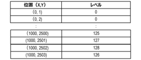
- the detection unit 702 adds information regarding the detection accuracy of the state of the user 100A to the effective range detected in step S902, and outputs it as range information 20A. Specifically, the detection unit 702 outputs information representing the detection accuracy of the state of the user 100A at each coordinate position using a gradation level (density), as shown in FIG. 13, as the range information 20A.
- a gradation level density
- FIG. 13 positions where the gradation level is greater than a specific value (for example, 0) are included in the effective range, and positions where the gradation level is less than or equal to the specific value are not included in the effective range.
- the detection unit 702 detects the effective range of the user 100A in the real space 101A from the captured image, and transmits range information 20A to the HMD 102B and camera 103B of the user 100B. Then, the HMD 102B sets a coordinate space whose origin is the position of the camera 103B placed in the real space 101B, as shown in FIG. 8, based on the range information 20A. The HMD 102B colors a coordinate position corresponding to each position in the effective range (coordinate position in the coordinate space of the real space 101B) according to the gradation level of the position in the effective range (the higher the gradation level, the darker the coloring). Generate display objects. Then, the HMD 102B displays the range display object together with the avatar 220A.
- each position of the range display object is displayed in a display format according to the detection accuracy of the state of the user 100A at the coordinate position of the real space 101A corresponding to the position.
- each position of the range display object does not need to be represented by a gradation display; for example, it may be displayed in a different color depending on the detection accuracy, or it may be displayed in a pattern depending on the detection accuracy. .
- range information 20 representing a two-dimensional coordinate space a process for detecting range information 20 representing a two-dimensional coordinate space has been described, but range information 20 representing a three-dimensional coordinate space that takes into account the height direction of real space may also be detected. Furthermore, the range information 20 usually only needs to be acquired once at the timing when the display of the avatar 220 is started.
- the user 100A sees the information (range display object) indicating the movement range of the avatar 220B of another user 100B, and recognizes the movement range of the avatar 220B and the detection accuracy of the state of the user 100B. Can be done. Therefore, the user 100A can grasp the possibility that the avatar 220B will be placed in an inappropriate position.
- the user 100A can avoid placing the avatar 220A of the user 100A in an unnatural position in the image viewed by the user 100B.
- the user 100A can prevent the avatar 220A of the user 100A from making unnatural movements in the image viewed by the user 100B by acting within the dark range of the gradation display color of the range display object. can be avoided.
- the HMD 102 also displays the movable range of the user 100 wearing the HMD 102.
- the HMD 102 will be described as an HMD 102A worn by the user 100A.
- the movable range of the avatar 220B of the user 100B is displayed on the HMD 102A.
- the video see-through type HMD 102A displays an image of a virtual space (a space that is not a real space)
- the user 100A plays with the avatar 220B in the virtual space, and images of them playing are captured.
- an image of the virtual space is displayed on the HMD 102A
- the user 100A cannot visually recognize the real space 101A in which he/she is currently located with the naked eye. Therefore, when the user 100A uses the HMD 102A to play a game that involves movement, there is a risk of colliding with an obstacle object placed in the real space 101A.
- the HMD 102A displays not only the movement range of the user 100B's avatar 220B but also the movable range of the user 100A in a gradation display based on the range information 20A detected by the camera 103A (virtual space superimposed on the image). That is, the HMD 102A displays a range display object that indicates a range (range in the image of the virtual space) corresponding to the movable range of the user 100A in the real space 101A.
- the "movable range of the user 100A" in the second embodiment may be the same range as the effective range of the user 100A.
- the "movable range of the user 100A" may be a range that includes the effective area of the user 100A and a range that cannot be viewed from the camera 103A due to the presence of an obstacle object (blind spot range 1104 in FIG. 11).
- FIG. 14 shows the configuration of the system 2 in the second embodiment.
- System 1 has the same basic configuration as system 2 according to the first embodiment.
- the HMD 102A also acquires the range information 20A of the user 100A, in order to know the movable range of the user 100A wearing the HMD 102A.
- the HMD 102A is similar to the see-through type HMD 500 (FIG. 5), but the object generation unit 503 generates a range display object representing a movable range for each of the two range information 20A and 20B. .
- the HMD 102A may display the two range display objects by switching them individually at regular time intervals, or may display them simultaneously in different color gradations.
- the user 100A can recognize the movable range of both himself and the avatar 220B. Therefore, the user 100A can avoid danger such as colliding with an obstacle object.
- the HMD includes a control device that controls the HMD (for example, a configuration in which the display section 505 is removed from the HMD 500) and a display section (for example, the display section 505 in the HMD 500). It's okay.
- the expression “A or less” may be replaced with “A or less than A (lower; shorter; less)” or “less than A (lower; shorter; less)”. You can read it differently. And, “greater than A (higher; longer; more)” may be read as “above A”, and “less than A (lower; shorter; fewer)” may be read as “below A”. .
- each functional unit in each of the above embodiments may or may not be separate hardware.
- the functions of two or more functional units may be realized by common hardware.
- Each of the plurality of functions of one functional unit may be realized by separate hardware.
- Two or more functions of one functional unit may be realized by common hardware.
- each functional unit may or may not be realized by hardware such as ASIC, FPGA, or DSP.
- the device may include a processor and a memory (storage medium) in which a control program is stored.
- the functions of at least some of the functional units included in the device may be realized by a processor reading a control program from a memory and executing it.
- the present invention provides a system or device with a program that implements one or more functions of the above embodiments via a network or a storage medium, and one or more processors in the computer of the system or device reads and executes the program. This can also be achieved by processing. It can also be realized by a circuit (for example, ASIC) that realizes one or more functions.
- a circuit for example, ASIC
- the disclosure of the above embodiments includes the following configurations, methods, and programs.
- (Configuration 1) A control device that controls a display device worn by a first user in a first real space, A virtual object that is placed at a position in the first real space that corresponds to a position of a second user in the second real space, and a range in which the virtual object can move in the first real space. and a control means for controlling the display device to display a range display object.
- the range in which the virtual object can move in the first real space is a range based on a captured image acquired by an imaging device in the second real space.
- the control device characterized in that: (Configuration 3) A movable range of the virtual object in the first real space corresponds to an effective range, The effective range is a range in the second real space in which the second user can move, and a range in which the second user can be detected from the captured image.
- the control device characterized in that: (Configuration 4) In the range display object, the control means may display each position in a movable range of the virtual object in the first real space to the second user at a position in the second real space corresponding to the position.
- the control device characterized in that: (Configuration 5) The detection accuracy of the second user's state is based on at least one of a range of the second user's whole body that is reflected in the captured image, and a size of the second user in the captured image.
- the control device characterized in that: (Configuration 6) acquisition means for acquiring range information indicating the effective range; generation means for generating the range display object based on the range information; 6.
- the control device according to any one of configurations 3 to 5, further comprising: (Configuration 7)
- the acquisition means further acquires status information indicating the status of the second user including the location of the second user, the generating means generates the virtual object based on the state information; has,
- the display device is a display device that is visible from the outside through the display,
- the control means controls the display device to display the virtual object and the range display object on the display.
- the control device according to any one of configurations 1 to 7, characterized in that: (Configuration 9)
- the control means controls the display device to display an image obtained by combining the virtual object and the range display object with respect to an image taken in front of the first user. 8.
- the control device according to any one of configurations 1 to 7, characterized in that: (Configuration 10) The control means displays an image of the virtual space, and displays a third area corresponding to a movable range of the first user in the first real space, which indicates an area in the image of the virtual space. controlling the display device to further display an image of 10.
- the control device according to any one of configurations 1 to 9, characterized in that: (Configuration 11) The control device according to any one of Configurations 1 to 10, an imaging device that captures the second real space to obtain a captured image; A system characterized by having.
- (Configuration 12) Based on the captured image, detect an effective range in the second physical space that is a range in which the second user can move and that is a range in which the second user can be detected from the captured image. further comprising detection means; A movable range of the virtual object in the first real space is a range corresponding to the effective range,
Landscapes
- Engineering & Computer Science (AREA)
- Theoretical Computer Science (AREA)
- Physics & Mathematics (AREA)
- General Physics & Mathematics (AREA)
- General Engineering & Computer Science (AREA)
- Computer Vision & Pattern Recognition (AREA)
- Multimedia (AREA)
- Software Systems (AREA)
- Evolutionary Computation (AREA)
- Databases & Information Systems (AREA)
- Computing Systems (AREA)
- General Health & Medical Sciences (AREA)
- Medical Informatics (AREA)
- Artificial Intelligence (AREA)
- Health & Medical Sciences (AREA)
- Human Computer Interaction (AREA)
- Computer Graphics (AREA)
- Computer Hardware Design (AREA)
- Processing Or Creating Images (AREA)
- User Interface Of Digital Computer (AREA)
- Position Input By Displaying (AREA)
Priority Applications (1)
| Application Number | Priority Date | Filing Date | Title |
|---|---|---|---|
| US18/991,084 US20250124614A1 (en) | 2022-06-29 | 2024-12-20 | Control device, system, control method for disposing virtual object in accordance with position of user |
Applications Claiming Priority (2)
| Application Number | Priority Date | Filing Date | Title |
|---|---|---|---|
| JP2022-104382 | 2022-06-29 | ||
| JP2022104382A JP2024004662A (ja) | 2022-06-29 | 2022-06-29 | 制御装置、システム、制御方法、プログラム |
Related Child Applications (1)
| Application Number | Title | Priority Date | Filing Date |
|---|---|---|---|
| US18/991,084 Continuation US20250124614A1 (en) | 2022-06-29 | 2024-12-20 | Control device, system, control method for disposing virtual object in accordance with position of user |
Publications (1)
| Publication Number | Publication Date |
|---|---|
| WO2024004306A1 true WO2024004306A1 (ja) | 2024-01-04 |
Family
ID=89381970
Family Applications (1)
| Application Number | Title | Priority Date | Filing Date |
|---|---|---|---|
| PCT/JP2023/013780 Ceased WO2024004306A1 (ja) | 2022-06-29 | 2023-04-03 | 制御装置、システム、制御方法、プログラム |
Country Status (3)
| Country | Link |
|---|---|
| US (1) | US20250124614A1 (enExample) |
| JP (1) | JP2024004662A (enExample) |
| WO (1) | WO2024004306A1 (enExample) |
Citations (3)
| Publication number | Priority date | Publication date | Assignee | Title |
|---|---|---|---|---|
| JP2018106297A (ja) * | 2016-12-22 | 2018-07-05 | キヤノンマーケティングジャパン株式会社 | 複合現実感提示システム、及び、情報処理装置とその制御方法、並びに、プログラム |
| JP2018106298A (ja) * | 2016-12-22 | 2018-07-05 | キヤノンマーケティングジャパン株式会社 | 画像処理装置、画像処理方法、コンピュータプログラム |
| JP6933849B1 (ja) * | 2020-09-03 | 2021-09-08 | 株式会社Abal | 体感型インターフェースシステム、及び、動作体感システム |
-
2022
- 2022-06-29 JP JP2022104382A patent/JP2024004662A/ja active Pending
-
2023
- 2023-04-03 WO PCT/JP2023/013780 patent/WO2024004306A1/ja not_active Ceased
-
2024
- 2024-12-20 US US18/991,084 patent/US20250124614A1/en active Pending
Patent Citations (3)
| Publication number | Priority date | Publication date | Assignee | Title |
|---|---|---|---|---|
| JP2018106297A (ja) * | 2016-12-22 | 2018-07-05 | キヤノンマーケティングジャパン株式会社 | 複合現実感提示システム、及び、情報処理装置とその制御方法、並びに、プログラム |
| JP2018106298A (ja) * | 2016-12-22 | 2018-07-05 | キヤノンマーケティングジャパン株式会社 | 画像処理装置、画像処理方法、コンピュータプログラム |
| JP6933849B1 (ja) * | 2020-09-03 | 2021-09-08 | 株式会社Abal | 体感型インターフェースシステム、及び、動作体感システム |
Also Published As
| Publication number | Publication date |
|---|---|
| JP2024004662A (ja) | 2024-01-17 |
| US20250124614A1 (en) | 2025-04-17 |
Similar Documents
| Publication | Publication Date | Title |
|---|---|---|
| US12169276B2 (en) | Head-mounted display for virtual and mixed reality with inside-out positional, user body and environment tracking | |
| KR102574874B1 (ko) | 헤드 마운트 디스플레이(hmd)를 이용한 화상회의를 위한 개선된 방법 및 시스템 | |
| US9852549B2 (en) | Image processing | |
| US20180101989A1 (en) | Headset removal in virtual, augmented, and mixed reality using an eye gaze database | |
| KR20230003154A (ko) | 3차원 환경들에서 아바타들의 제시 | |
| JP7762780B2 (ja) | 非均一ステレオレンダリング | |
| WO2003063086A1 (fr) | Systeme de traitement d'images, appareil de traitement d'images, et appareil d'affichage | |
| JP2020154430A (ja) | 複数のマーカを備えたデバイス | |
| WO2024004306A1 (ja) | 制御装置、システム、制御方法、プログラム | |
| JP7593334B2 (ja) | 表示装置、画像生成方法及びプログラム | |
| US20250291408A1 (en) | Display system, display method, and storage medium | |
| JP5332127B2 (ja) | 頭部装着型表示装置 | |
| JP2025139385A (ja) | 表示システム、表示方法、およびプログラム | |
| JP2023178093A (ja) | 表示装置、制御方法及びプログラム |
Legal Events
| Date | Code | Title | Description |
|---|---|---|---|
| 121 | Ep: the epo has been informed by wipo that ep was designated in this application |
Ref document number: 23830760 Country of ref document: EP Kind code of ref document: A1 |
|
| NENP | Non-entry into the national phase |
Ref country code: DE |
|
| 122 | Ep: pct application non-entry in european phase |
Ref document number: 23830760 Country of ref document: EP Kind code of ref document: A1 |