WO2024004089A1 - Acoustic signal output device - Google Patents
Acoustic signal output device Download PDFInfo
- Publication number
- WO2024004089A1 WO2024004089A1 PCT/JP2022/026011 JP2022026011W WO2024004089A1 WO 2024004089 A1 WO2024004089 A1 WO 2024004089A1 JP 2022026011 W JP2022026011 W JP 2022026011W WO 2024004089 A1 WO2024004089 A1 WO 2024004089A1
- Authority
- WO
- WIPO (PCT)
- Prior art keywords
- acoustic signal
- sound
- sound hole
- output device
- emitted
- Prior art date
Links
- 230000005236 sound signal Effects 0.000 claims description 60
- 239000012528 membrane Substances 0.000 claims description 24
- 230000006870 function Effects 0.000 claims description 18
- 230000035945 sensitivity Effects 0.000 claims description 14
- 238000012546 transfer Methods 0.000 claims description 13
- 238000012986 modification Methods 0.000 description 124
- 230000004048 modification Effects 0.000 description 124
- 238000000034 method Methods 0.000 description 66
- 210000000613 ear canal Anatomy 0.000 description 57
- 238000013461 design Methods 0.000 description 45
- 239000011358 absorbing material Substances 0.000 description 31
- 238000010586 diagram Methods 0.000 description 31
- 238000009826 distribution Methods 0.000 description 19
- 238000012937 correction Methods 0.000 description 18
- 230000000694 effects Effects 0.000 description 18
- 238000009434 installation Methods 0.000 description 18
- 210000005069 ears Anatomy 0.000 description 16
- 239000000463 material Substances 0.000 description 15
- 101100059544 Arabidopsis thaliana CDC5 gene Proteins 0.000 description 13
- 101150115300 MAC1 gene Proteins 0.000 description 13
- 210000003128 head Anatomy 0.000 description 13
- 239000011521 glass Substances 0.000 description 11
- 238000002474 experimental method Methods 0.000 description 10
- 101100244969 Arabidopsis thaliana PRL1 gene Proteins 0.000 description 9
- 102100039558 Galectin-3 Human genes 0.000 description 9
- 101100454448 Homo sapiens LGALS3 gene Proteins 0.000 description 9
- 101150051246 MAC2 gene Proteins 0.000 description 9
- 230000000903 blocking effect Effects 0.000 description 7
- 239000002184 metal Substances 0.000 description 7
- 230000002829 reductive effect Effects 0.000 description 7
- 238000007789 sealing Methods 0.000 description 7
- 229920003002 synthetic resin Polymers 0.000 description 7
- 239000000057 synthetic resin Substances 0.000 description 7
- 230000002745 absorbent Effects 0.000 description 6
- 239000002250 absorbent Substances 0.000 description 6
- 230000002238 attenuated effect Effects 0.000 description 6
- 238000010521 absorption reaction Methods 0.000 description 4
- 230000003111 delayed effect Effects 0.000 description 4
- 229920002799 BoPET Polymers 0.000 description 3
- 238000006243 chemical reaction Methods 0.000 description 3
- 230000002452 interceptive effect Effects 0.000 description 3
- 238000012545 processing Methods 0.000 description 3
- 230000001629 suppression Effects 0.000 description 3
- 241000282412 Homo Species 0.000 description 2
- 238000013459 approach Methods 0.000 description 2
- 238000002592 echocardiography Methods 0.000 description 2
- 230000000149 penetrating effect Effects 0.000 description 2
- 230000002093 peripheral effect Effects 0.000 description 2
- 229920000139 polyethylene terephthalate Polymers 0.000 description 2
- 239000005020 polyethylene terephthalate Substances 0.000 description 2
- 230000002441 reversible effect Effects 0.000 description 2
- OHVLMTFVQDZYHP-UHFFFAOYSA-N 1-(2,4,6,7-tetrahydrotriazolo[4,5-c]pyridin-5-yl)-2-[4-[2-[[3-(trifluoromethoxy)phenyl]methylamino]pyrimidin-5-yl]piperazin-1-yl]ethanone Chemical compound N1N=NC=2CN(CCC=21)C(CN1CCN(CC1)C=1C=NC(=NC=1)NCC1=CC(=CC=C1)OC(F)(F)F)=O OHVLMTFVQDZYHP-UHFFFAOYSA-N 0.000 description 1
- HMUNWXXNJPVALC-UHFFFAOYSA-N 1-[4-[2-(2,3-dihydro-1H-inden-2-ylamino)pyrimidin-5-yl]piperazin-1-yl]-2-(2,4,6,7-tetrahydrotriazolo[4,5-c]pyridin-5-yl)ethanone Chemical compound C1C(CC2=CC=CC=C12)NC1=NC=C(C=N1)N1CCN(CC1)C(CN1CC2=C(CC1)NN=N2)=O HMUNWXXNJPVALC-UHFFFAOYSA-N 0.000 description 1
- LDXJRKWFNNFDSA-UHFFFAOYSA-N 2-(2,4,6,7-tetrahydrotriazolo[4,5-c]pyridin-5-yl)-1-[4-[2-[[3-(trifluoromethoxy)phenyl]methylamino]pyrimidin-5-yl]piperazin-1-yl]ethanone Chemical compound C1CN(CC2=NNN=C21)CC(=O)N3CCN(CC3)C4=CN=C(N=C4)NCC5=CC(=CC=C5)OC(F)(F)F LDXJRKWFNNFDSA-UHFFFAOYSA-N 0.000 description 1
- WZFUQSJFWNHZHM-UHFFFAOYSA-N 2-[4-[2-(2,3-dihydro-1H-inden-2-ylamino)pyrimidin-5-yl]piperazin-1-yl]-1-(2,4,6,7-tetrahydrotriazolo[4,5-c]pyridin-5-yl)ethanone Chemical compound C1C(CC2=CC=CC=C12)NC1=NC=C(C=N1)N1CCN(CC1)CC(=O)N1CC2=C(CC1)NN=N2 WZFUQSJFWNHZHM-UHFFFAOYSA-N 0.000 description 1
- IHCCLXNEEPMSIO-UHFFFAOYSA-N 2-[4-[2-(2,3-dihydro-1H-inden-2-ylamino)pyrimidin-5-yl]piperidin-1-yl]-1-(2,4,6,7-tetrahydrotriazolo[4,5-c]pyridin-5-yl)ethanone Chemical compound C1C(CC2=CC=CC=C12)NC1=NC=C(C=N1)C1CCN(CC1)CC(=O)N1CC2=C(CC1)NN=N2 IHCCLXNEEPMSIO-UHFFFAOYSA-N 0.000 description 1
- YLZOPXRUQYQQID-UHFFFAOYSA-N 3-(2,4,6,7-tetrahydrotriazolo[4,5-c]pyridin-5-yl)-1-[4-[2-[[3-(trifluoromethoxy)phenyl]methylamino]pyrimidin-5-yl]piperazin-1-yl]propan-1-one Chemical compound N1N=NC=2CN(CCC=21)CCC(=O)N1CCN(CC1)C=1C=NC(=NC=1)NCC1=CC(=CC=C1)OC(F)(F)F YLZOPXRUQYQQID-UHFFFAOYSA-N 0.000 description 1
- 229920000742 Cotton Polymers 0.000 description 1
- 241001465754 Metazoa Species 0.000 description 1
- 241000282577 Pan troglodytes Species 0.000 description 1
- 230000003321 amplification Effects 0.000 description 1
- 210000000988 bone and bone Anatomy 0.000 description 1
- 230000003247 decreasing effect Effects 0.000 description 1
- 230000007613 environmental effect Effects 0.000 description 1
- 239000011796 hollow space material Substances 0.000 description 1
- 239000004615 ingredient Substances 0.000 description 1
- 230000000670 limiting effect Effects 0.000 description 1
- 239000004745 nonwoven fabric Substances 0.000 description 1
- 238000003199 nucleic acid amplification method Methods 0.000 description 1
- -1 polyethylene terephthalate Polymers 0.000 description 1
- 230000000644 propagated effect Effects 0.000 description 1
- 230000001902 propagating effect Effects 0.000 description 1
- 230000035807 sensation Effects 0.000 description 1
- 238000004088 simulation Methods 0.000 description 1
Images


Classifications
-
- H—ELECTRICITY
- H04—ELECTRIC COMMUNICATION TECHNIQUE
- H04R—LOUDSPEAKERS, MICROPHONES, GRAMOPHONE PICK-UPS OR LIKE ACOUSTIC ELECTROMECHANICAL TRANSDUCERS; DEAF-AID SETS; PUBLIC ADDRESS SYSTEMS
- H04R1/00—Details of transducers, loudspeakers or microphones
- H04R1/10—Earpieces; Attachments therefor ; Earphones; Monophonic headphones
-
- H—ELECTRICITY
- H04—ELECTRIC COMMUNICATION TECHNIQUE
- H04R—LOUDSPEAKERS, MICROPHONES, GRAMOPHONE PICK-UPS OR LIKE ACOUSTIC ELECTROMECHANICAL TRANSDUCERS; DEAF-AID SETS; PUBLIC ADDRESS SYSTEMS
- H04R1/00—Details of transducers, loudspeakers or microphones
- H04R1/20—Arrangements for obtaining desired frequency or directional characteristics
- H04R1/22—Arrangements for obtaining desired frequency or directional characteristics for obtaining desired frequency characteristic only
- H04R1/28—Transducer mountings or enclosures modified by provision of mechanical or acoustic impedances, e.g. resonator, damping means
-
- H—ELECTRICITY
- H04—ELECTRIC COMMUNICATION TECHNIQUE
- H04R—LOUDSPEAKERS, MICROPHONES, GRAMOPHONE PICK-UPS OR LIKE ACOUSTIC ELECTROMECHANICAL TRANSDUCERS; DEAF-AID SETS; PUBLIC ADDRESS SYSTEMS
- H04R1/00—Details of transducers, loudspeakers or microphones
- H04R1/20—Arrangements for obtaining desired frequency or directional characteristics
- H04R1/32—Arrangements for obtaining desired frequency or directional characteristics for obtaining desired directional characteristic only
- H04R1/34—Arrangements for obtaining desired frequency or directional characteristics for obtaining desired directional characteristic only by using a single transducer with sound reflecting, diffracting, directing or guiding means
Definitions
- the present invention relates to an acoustic signal output device, and particularly to an acoustic signal output device that does not seal the ear canal.
- open-ear earphones and headphones have the problem of large sound leakage to the surroundings. Such a problem is not limited to open-ear earphones or headphones, but is a problem common to audio signal output devices that do not seal the ear canal.
- the present invention has been made in view of these points, and it is an object of the present invention to provide an acoustic signal output device that does not seal the ear canal and can suppress sound leakage to the surroundings.
- An acoustic signal output device includes a driver unit and a casing that houses the driver unit therein.
- the acoustic signal emitted from the driver unit to one side is referred to as a first acoustic signal
- the acoustic signal emitted from the driver unit to the other side is referred to as a second acoustic signal.
- the wall of the housing is provided with one or more first sound holes that lead out the first acoustic signal to the outside, and one or more second sound holes that lead out the second sound signal to the outside. .
- a first point based on a predetermined first point where the first sound signal arrives;
- the attenuation rate of the first acoustic signal at a second point farther from the acoustic signal output device than the attenuation rate of the acoustic signal due to air propagation at the second point with respect to the first point is less than or equal to a predetermined value. or the amount of attenuation of the first acoustic signal at the second point with respect to the first point is due to air propagation of the acoustic signal at the second point with respect to the first point. It is designed to be at least a predetermined value larger than the amount of attenuation.
- This structure can suppress sound leakage to the surroundings.
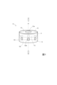
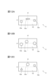
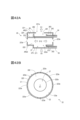
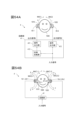
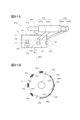
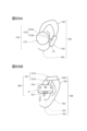
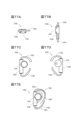
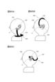
- FIG. 1 is a transparent perspective view illustrating the configuration of the acoustic signal output device of the first embodiment.
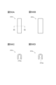
- FIG. 2A is a transparent plan view illustrating the configuration of the acoustic signal output device of the first embodiment.
- FIG. 2B is a transparent front view illustrating the configuration of the acoustic signal output device of the first embodiment.
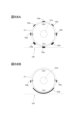
- FIG. 2C is a bottom view illustrating the configuration of the acoustic signal output device of the first embodiment.
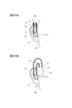
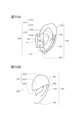
- FIG. 3A is a 2BA-2BA end view of FIG. 2B.
- FIG. 3B is a 2A-2A end view of FIG. 2A.
- FIG. 3C is a 2BC-2BC end view of FIG. 2B.
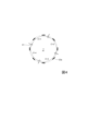
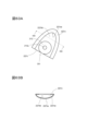
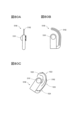
- FIG. 4 is a conceptual diagram for illustrating the arrangement of sound holes.
- FIG. 4 is a conceptual diagram for illustrating the arrangement of sound holes.
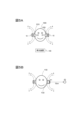
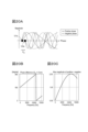
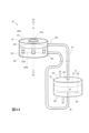
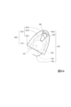
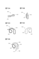
- FIG. 5A is a diagram illustrating a usage state of the acoustic signal output device of the first embodiment.
- FIG. 5B is a diagram illustrating conditions for observing the acoustic signal emitted from the acoustic signal output device of the first embodiment.
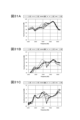
- FIG. 6 is a graph illustrating the frequency characteristics of the acoustic signal observed at position P1 in FIG. 5B.
- FIG. 7 is a graph illustrating the frequency characteristics of the acoustic signal observed at position P2 in FIG. 5B.
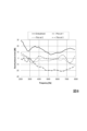
- FIG. 8 is a graph illustrating the difference between the acoustic signal observed at position P1 and the acoustic signal observed at position P2.
- 9A and 9B are graphs illustrating the relationship between the area ratio of sound holes and sound leakage.
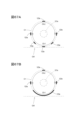
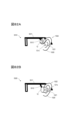
- FIG. 10A is a front view for illustrating the arrangement of sound holes.
- FIG. 10B is a conceptual diagram for illustrating the arrangement of sound holes.
- FIG. 11A is a front view for illustrating the arrangement of sound holes.
- FIG. 11B is a conceptual diagram for illustrating the arrangement of sound holes.
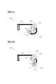
- 12A to 12C are front views illustrating modified examples of the arrangement of sound holes.
- 13A and 13B are transparent plan views for illustrating modified examples of the arrangement of sound holes.
- FIGS. 14A and 14B are conceptual diagrams illustrating modified examples of the arrangement of sound holes.
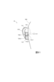
- FIG. 15A is a transparent front view for illustrating a modification of the arrangement of sound holes.
- FIG. 15B is an end view illustrating a modification of the arrangement of sound holes and a modification of the distance between the driver unit and the housing.
- FIG. 16A to 16C are end views illustrating a modification of the acoustic signal output device of the first embodiment.
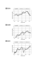
- FIG. 17 is a graph comparing the frequency characteristics of the acoustic signals observed at position P1 in FIG. 5B.
- FIG. 18 is a graph illustrating the frequency characteristics of the acoustic signal observed at position P2 in FIG. 5B.
- FIG. 19 is a graph illustrating the difference between the acoustic signal observed at position P1 and the acoustic signal observed at position P2.
- FIG. 20A is for illustrating the relationship between the acoustic signal AC1 (normal phase signal) emitted to the outside from the first sound hole and the acoustic signal AC2 (negative phase signal) emitted to the outside from the second sound hole.
- FIG. 20B shows the acoustic signal AC1 (positive phase signal) emitted to the outside from the first sound hole and the external signal from the second sound hole when the distance between the first sound hole and the second sound hole is 1.5 cm.
- FIG. 3 is a diagram for illustrating the relationship between the phase difference with the acoustic signal AC2 (reverse phase signal) emitted to the acoustic signal AC1 and the frequency of the acoustic signals AC1 and AC2.
- FIG. 20C shows the acoustic signal AC1 (normal phase signal) and the acoustic signal observed at a position 15 cm outside the acoustic signal output device when the distance between the first sound hole and the second sound hole is 1.5 cm.
- FIG. 21A is a diagram illustrating a state in which the acoustic signal output device is modeled as an enclosure.
- FIG. 21B is a diagram for illustrating the relationship between the resonance frequency f H [Hz] determined based on the Helmholtz resonance of the enclosure and the magnitude of the acoustic signal AC2 (negative phase signal) inside the enclosure.
- FIG. 21C shows the difference in phase between the acoustic signal AC2 (negative phase signal) emitted from the second sound hole and the acoustic signal AC2 (negative phase signal) emitted from the driver unit.
- FIG. 3 is a diagram for illustrating the relationship between the frequency and the frequency of a negative phase signal.
- FIG. 22A is a conceptual diagram for explaining the state of acoustic signals AC1 and AC2 observed at position P2.
- FIG. 22B shows the resonance frequency f H [Hz] determined based on the Helmholtz resonance of the enclosure when the distance between the first sound hole and the second sound hole is 1.5 cm.
- FIG. 22C shows the acoustic performance when the resonance frequency f H [Hz] determined based on the Helmholtz resonance of the enclosure is appropriately adjusted when the distance between the first sound hole and the second sound hole is 1.5 cm.
- FIG. 23A is a diagram modeling the relationship between the first sound hole, the second sound hole, and the position P2. In this example, the first sound hole and the second sound hole are separated from each other by a distance D pn .
- FIG. 23B shows the positions when the delay ⁇ c for suppressing the phase difference between the acoustic signal AC1 and the acoustic signal AC2 at P2 is applied to the acoustic signal AC2 (with ⁇ c ) and when it is not applied (without ⁇ c ). It is a figure for illustrating the relationship between the phase difference of acoustic signals AC1 and AC2 observed at P2, and frequency.
- FIG. 24A is a conceptual diagram for explaining the state of acoustic signals AC1 and AC2 observed at position P2.
- FIG. 24B is a diagram illustrating the relationship between frequency and phase characteristics.
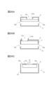
- 25A to 25C are modified examples of the end view 2A-2A of FIG. 2A for explaining modified examples of the acoustic signal output device.
- 26A to 26C are modified examples of the 2A-2A end view of FIG. 2A for explaining modified examples of the acoustic signal output device.
- 27A to 27C are modified examples of the end view 2A-2A of FIG. 2A for explaining modified examples of the acoustic signal output device.
- 28A and 28B are modified examples of the 2A-2A end view of FIG. 2A for explaining modified examples of the acoustic signal output device.
- 29A and 29B are modified examples of the 2A-2A end view of FIG. 2A for explaining modified examples of the acoustic signal output device.
- 30A and 30B are modified examples of the 2A-2A end view of FIG. 2A for explaining modified examples of the acoustic signal output device.
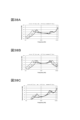
- FIG. 31A is a graph comparing the frequency characteristics of the acoustic signals observed at position P1 in FIG. 5B for acoustic signal output devices having different total opening areas of sound holes.
- FIG. 31B is a graph illustrating the frequency characteristics of the acoustic signals observed at position P2 in FIG. 5B for acoustic signal output devices having different total opening areas of sound holes.
- FIG. 31C is a graph illustrating the difference between the acoustic signal observed at position P1 and the acoustic signal observed at position P2 for acoustic signal output devices having different total opening areas of sound holes.
- FIG. 32A is a graph comparing the frequency characteristics of the acoustic signals observed at position P1 in FIG.
- FIG. 32B is a graph illustrating the frequency characteristics of the acoustic signals observed at position P2 in FIG. 5B for acoustic signal output devices with different volumes of internal spaces of the casings.
- FIG. 32C is a graph illustrating the difference between the acoustic signal observed at position P1 and the acoustic signal observed at position P2 for acoustic signal output devices having different volumes of internal spaces of the casings.
- FIG. 33A is a graph comparing the frequency characteristics of the acoustic signal observed at position P1 in FIG.
- FIG. 33B is a graph illustrating the frequency characteristics of the acoustic signal observed at position P2 in FIG. 5B for the acoustic signal output device of the embodiment and the open type acoustic signal output device.
- FIG. 33C is a graph illustrating the difference between the acoustic signal observed at position P1 and the acoustic signal observed at position P2 for the acoustic signal output device of the embodiment and the open type acoustic signal output device.
- 34A to 34C are modified examples of the end view 2A-2A of FIG.
- FIG. 37A is a graph comparing the sound pressure level at position P2 of acoustic signal AC1 at each frequency for vibrating membranes having different thicknesses.
- FIG. 37B is a graph comparing the sound pressure level at position P2 of acoustic signal AC2 at each frequency for vibrating membranes having different thicknesses.
- FIG. 37C is a graph comparing sound pressure levels at a position P2 of an acoustic signal obtained by canceling the acoustic signal AC1 at each frequency with the acoustic signal AC2 for vibrating membranes having different thicknesses.
- FIG. 38A is a graph comparing sound pressure levels at position P2 of acoustic signal AC1 at each frequency for vibrating membranes having different thicknesses.
- FIG. 38B is a graph comparing the sound pressure level at position P2 of acoustic signal AC2 at each frequency for vibrating membranes having different thicknesses.
- FIG. 38C is a graph comparing sound pressure levels at a position P2 of an acoustic signal obtained by canceling the acoustic signal AC1 at each frequency with the acoustic signal AC2 for vibrating membranes having different thicknesses.
- FIG. 39A is a graph comparing the phase of the acoustic signal AC1 at each frequency for vibrating membranes having different thicknesses.
- FIG. 39B is a graph comparing the phase of the acoustic signal AC2 at each frequency for vibrating membranes having different thicknesses.
- FIG. 39C is a graph comparing the phases of acoustic signals obtained by canceling the acoustic signal AC1 at each frequency with the acoustic signal AC2 for vibrating membranes having different thicknesses.
- FIG. 39A is a graph comparing the phase of the acoustic signal AC1 at each frequency for vibrating membranes having different thicknesses.
- FIG. 39B is a graph comparing the phase of the a
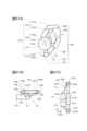
- FIG. 40 is a transparent perspective view illustrating the configuration of the acoustic signal output device of the second embodiment.
- FIG. 41A is a transparent plan view illustrating the configuration of the acoustic signal output device of the second embodiment.
- FIG. 41B is a transparent front view illustrating the configuration of the acoustic signal output device of the first embodiment.
- FIG. 41C is a bottom view illustrating the configuration of the acoustic signal output device of the first embodiment.
- FIG. 42A is an end view taken along line 21A-21A of FIG. 41B.
- FIG. 42B is a sectional view taken along line 21B-21B in FIG. 41A.
- FIGS. 43A and 43B are diagrams illustrating how the acoustic signal output device of the second embodiment is used.
- FIG. 43A and 43B are diagrams illustrating how the acoustic signal output device of the second embodiment is used.
- FIG. 44 is a transparent perspective view illustrating a modification of the acoustic signal output device of the second embodiment.
- FIG. 45A is a transparent plan view illustrating a modification of the acoustic signal output device of the second embodiment.
- FIG. 45B is a transparent front view illustrating a modification of the acoustic signal output device of the second embodiment.
- FIG. 45C is a bottom view illustrating a modification of the acoustic signal output device of the second embodiment.
- FIG. 46 is an end view taken along line 25A-25A of FIG. 45B.
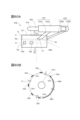
- FIG. 47 is a perspective view illustrating the configuration of an acoustic signal output device according to the third embodiment.
- FIG. 48 is a transparent perspective view illustrating the configuration of the acoustic signal output device of the third embodiment.
- FIG. 49 is a conceptual diagram for illustrating the arrangement of sound holes.
- 50A to 50C are block diagrams illustrating the configuration of the circuit section.
- FIG. 51 is a diagram illustrating the usage state of the acoustic signal output device of the third embodiment.
- FIG. 52A is a perspective view illustrating a modification of the acoustic signal output device of the third embodiment.
- FIG. 52B is a conceptual diagram illustrating a modification of the arrangement of sound holes.
- FIG. 53A is a transparent perspective view illustrating a modification of the acoustic signal output device of the third embodiment.
- FIG. 53B is a diagram illustrating a modification of the acoustic signal output device of the third embodiment.
- FIG. 54A is a diagram illustrating the configuration of the acoustic signal output device of the fourth embodiment.
- FIG. 54B is a diagram illustrating a modification of the acoustic signal output device of the fourth embodiment.
- FIG. 55A is a transparent front view illustrating the configuration of the acoustic signal output device of the fifth embodiment.
- FIG. 55B is a transparent plan view illustrating the configuration of the acoustic signal output device of the fifth embodiment.
- FIG. 55C is a transparent right side view illustrating the configuration of the acoustic signal output device of the fifth embodiment.
- FIG. 56A is a plan view illustrating the fixing part of the fifth embodiment.
- FIG. 56B is a right side view illustrating the fixing part of the fifth embodiment.
- FIG. 56C is a front view illustrating the fixing part of the fifth embodiment.
- FIG. 56D is a cross-sectional view taken along line 36A-36A in FIG. 56A.
- FIG. 57A is a transparent front view illustrating a modification of the acoustic signal output device of the fifth embodiment.
- FIG. 57B is a transparent plan view illustrating a modification of the acoustic signal output device of the fifth embodiment.
- FIG. 57C is a transparent right side view illustrating a modification of the acoustic signal output device of the fifth embodiment.
- FIG. 58 is a front view illustrating a modification of the acoustic signal output device of the fifth embodiment.
- FIG. 60A is a plan view illustrating a modification of the acoustic signal output device of the fifth embodiment.
- FIG. 60B is a conceptual diagram illustrating a modification of the arrangement of sound holes.
- FIG. 61A is a plan view illustrating a modification of the acoustic signal output device of the fifth embodiment.
- FIG. 61B is a conceptual diagram illustrating a modification of the arrangement of sound holes.
- FIG. 62 is a transparent front view illustrating the configuration of the acoustic signal output device of the fifth embodiment.
- FIG. 63A is a rear view illustrating the configuration of the acoustic signal output device of the fifth embodiment.
- FIG. 63B is a sectional view taken along line 43A-43A in FIG. 63A.
- FIG. 64 is a transparent front view illustrating a modification of the acoustic signal output device of the fifth embodiment.
- FIG. 65 is a transparent front view illustrating a modification of the acoustic signal output device of the fifth embodiment.
- FIG. 66A is a transparent front view illustrating a modification of the acoustic signal output device of the fifth embodiment.
- FIG. 66B is a transparent bottom view illustrating a modification of the acoustic signal output device of the fifth embodiment.
- FIG. 66C is a plan view illustrating a modification of the acoustic signal output device of the fifth embodiment.
- FIGS. 68A and 68B are conceptual diagrams illustrating modified examples of the arrangement of sound holes.
- FIGS. 68A and 68B are conceptual diagrams illustrating modified examples of the arrangement of sound holes.
- FIG. 69A is a front view illustrating a modification of the acoustic signal output device of the sixth embodiment.
- FIG. 69B is a perspective view illustrating a modification of the acoustic signal output device of the sixth embodiment.
- FIG. 70A is a perspective view illustrating a modification of the acoustic signal output device of the sixth embodiment.
- FIG. 70B is a plan view illustrating a modification of the acoustic signal output device of the sixth embodiment.
- FIG. 69A is a front view illustrating a modification of the acoustic signal output device of the sixth embodiment.
- FIG. 69B is a perspective view illustrating a modification of the acoustic signal output device of the sixth embodiment.
- FIG. 70A is a perspective view
- FIG. 71A is a plan view illustrating a modification of the acoustic signal output device of the sixth embodiment.
- FIG. 71B is a plan view illustrating a modification of the acoustic signal output device of the sixth embodiment.
- FIG. 72A is a plan view illustrating a modification of the acoustic signal output device of the sixth embodiment.
- FIG. 72B is a transparent perspective view illustrating a modification of the acoustic signal output device of the sixth embodiment.
- FIG. 73A is a plan view illustrating a modification of the acoustic signal output device of the sixth embodiment.
- FIG. 73B is a right side view illustrating a modification of the acoustic signal output device of the sixth embodiment.
- FIG. 73C is a front view illustrating a modification of the acoustic signal output device of the sixth embodiment.
- FIG. 73D is a rear view illustrating a modification of the acoustic signal output device of the sixth embodiment.
- FIG. 73E is a front view illustrating a usage state of a modified example of the acoustic signal output device of the sixth embodiment.
- FIG. 74A is a perspective view illustrating a modification of the acoustic signal output device of the sixth embodiment.
- FIG. 74B is a perspective view illustrating a modification of the acoustic signal output device of the sixth embodiment.
- FIG. 74C is a perspective view illustrating a usage state of a modified example of the acoustic signal output device of the sixth embodiment.
- FIG. 75A and 75B are front views for illustrating the usage state of a modified example of the acoustic signal output device of the sixth embodiment.
- FIG. 76A is a front view illustrating a modification of the acoustic signal output device of the sixth embodiment.
- FIG. 76B is a rear view illustrating a modification of the acoustic signal output device of the sixth embodiment.
- FIG. 76C is a front view illustrating a usage state of a modified example of the acoustic signal output device of the sixth embodiment.
- FIG. 77A is a plan view illustrating a modification of the acoustic signal output device of the sixth embodiment.
- FIG. 77B is a right side view illustrating a modification of the acoustic signal output device of the sixth embodiment.
- FIG. 77C is a front view illustrating a modification of the acoustic signal output device of the sixth embodiment.
- FIG. 77D is a rear view illustrating a modification of the acoustic signal output device of the sixth embodiment.
- FIG. 77E is a front view illustrating a usage state of a modified example of the acoustic signal output device of the sixth embodiment.
- FIG. 78A is a plan view illustrating a modification of the acoustic signal output device of the sixth embodiment.
- FIG. 78B is a front view illustrating a modification of the acoustic signal output device of the sixth embodiment.
- FIG. 78C is a rear view illustrating a modification of the acoustic signal output device of the sixth embodiment.
- FIG. 78D is a front view illustrating a usage state of a modified example of the acoustic signal output device of the sixth embodiment.
- FIG. 79A is a plan view illustrating a modification of the acoustic signal output device of the sixth embodiment.
- FIG. 79B is a front view illustrating a modification of the acoustic signal output device of the sixth embodiment.
- FIG. 79C is a rear view illustrating a modification of the acoustic signal output device of the sixth embodiment.
- FIG. 79D is a front view illustrating a usage state of a modified example of the acoustic signal output device of the sixth embodiment.
- FIG. 80A is a left side view illustrating a modification of the acoustic signal output device of the sixth embodiment.
- FIG. 80B is a front view illustrating a modification of the acoustic signal output device of the sixth embodiment.
- FIG. 80C is a front view illustrating a usage state of a modified example of the acoustic signal output device of the sixth embodiment.
- FIG. 81A is a plan view illustrating a modification of the acoustic signal output device of the sixth embodiment.
- FIG. 81B is a right side view illustrating a modification of the acoustic signal output device of the sixth embodiment.
- FIG. 81C is a front view illustrating a modification of the acoustic signal output device of the sixth embodiment.
- FIG. 81D is a rear view illustrating a modification of the acoustic signal output device of the sixth embodiment.
- FIG. 81E is a front view illustrating a usage state of a modified example of the acoustic signal output device of the sixth embodiment.
- FIG. 82A and FIG. 82B are conceptual diagrams for illustrating a modification of the acoustic signal output device of the sixth embodiment.
- FIG. 83A and FIG. 83B are conceptual diagrams for illustrating a modification of the acoustic signal output device of the sixth embodiment.
- 84A and 84B are conceptual diagrams for illustrating a modification of the acoustic signal output device of the sixth embodiment.
- 85A to 85C are conceptual diagrams for illustrating a modification of the acoustic signal output device of the sixth embodiment.
- the audio signal output device 10 of this embodiment is an audio listening device (for example, open-ear earphones, headphones, etc.) that is worn without sealing the ear canal of the user. As illustrated in FIG. 1, FIG. 2A to FIG. 2C, and FIG. 3A to FIG. It has a driver unit 11 that converts into a signal and outputs it, and a casing 12 that houses the driver unit 11 inside.
- the driver unit (speaker driver unit) 11 emits (sounds) an acoustic signal AC1 (first acoustic signal) based on the input output signal to one side (direction D1), and emits an opposite phase signal ( This is a device (a device with a speaker function) that emits an acoustic signal AC2 (second acoustic signal), which is an approximation signal of a phase-inverted signal) or an anti-phase signal, to the other side (direction D2 side).
- the acoustic signal emitted from the driver unit 11 to one side is called an acoustic signal AC1 (first acoustic signal)
- the acoustic signal emitted from the driver unit 11 to the other side is called an acoustic signal AC1 (first acoustic signal).
- This will be referred to as acoustic signal AC2 (second acoustic signal).
- the driver unit 11 includes a diaphragm 113 that emits an acoustic signal AC1 in the D1 direction from one surface 113a by vibration, and emits an acoustic signal AC2 in the D2 direction from the other surface 113b by this vibration (Fig.
- the diaphragm 113 vibrates based on the input output signal, so that the acoustic signal AC1 is emitted from one side surface 111 to the D1 direction side, and an opposite phase signal of the acoustic signal AC1 or The acoustic signal AC2, which is an approximation signal of the opposite phase signal, is emitted from the other side 112 in the direction D2. That is, the acoustic signal AC2 is emitted secondary to the emission of the acoustic signal AC1.
- the D2 direction (the other side) is, for example, the opposite direction to the D1 direction (one side), but the D2 direction does not have to be strictly the opposite direction to the D1 direction, and if the D2 direction is different from the D1 direction, good.
- the relationship between one side (D1 direction) and the other side (D2 direction) depends on the type and shape of the driver unit 11.
- the acoustic signal AC2 may be strictly an antiphase signal of the acoustic signal AC1, or the acoustic signal AC2 may be an approximation signal of the antiphase signal of the acoustic signal AC1. .
- the approximate signal of the anti-phase signal of the acoustic signal AC1 may be a signal obtained by (1) shifting the phase of the anti-phase signal of the acoustic signal AC1, or (2) an anti-phase signal of the acoustic signal AC1. It may be a signal obtained by changing the amplitude (amplification or attenuation) of (3) the acoustic signal AC1, or it may be a signal obtained by shifting the phase of the opposite phase signal of the acoustic signal AC1 and further changing the amplitude. good.
- the phase difference between the anti-phase signal of the acoustic signal AC1 and its approximate signal is desirably ⁇ 1 % or less of one cycle of the anti-phase signal of the acoustic signal AC1.
- Examples of ⁇ 1 % are 1%, 3%, 5%, 10%, 20%, etc. Further, it is desirable that the difference between the amplitude of the anti-phase signal of the acoustic signal AC1 and the amplitude of its approximate signal is ⁇ 2 % or less of the amplitude of the anti-phase signal of the acoustic signal AC1. Examples of ⁇ 2 % are 1%, 3%, 5%, 10%, 20%, etc.
- Examples of the driver unit 11 include a dynamic type, a balanced armature type, a hybrid type of a dynamic type and a balanced armature type, and a condenser type. Furthermore, there are no limitations on the shapes of the driver unit 11 and the diaphragm 113.
- the outer shape of the driver unit 11 is a substantially cylindrical shape with both end surfaces, and the diaphragm 113 is a substantially disc shape, but this does not limit the present invention. isn't it.
- the outer shape of the driver unit 11 may be a rectangular parallelepiped, and the diaphragm 113 may be a dome shape.
- examples of the acoustic signal are sounds such as music, voice, sound effects, and environmental sounds.
- the housing 12 is a hollow member having a wall portion on the outside, and houses the driver unit 11 inside.
- the driver unit 11 is fixed to an end inside the housing 12 on the D1 direction side.
- this does not limit the invention.
- the shape of the housing 12 for example, it is desirable that the shape of the housing 12 be rotationally symmetrical (line symmetrical) or approximately rotationally symmetrical about the axis A1 extending along the D1 direction. This makes it easy to provide the sound holes 123a (details will be described later) so that variations in sound energy emitted from the housing 12 from direction to direction are reduced. As a result, it becomes easy to reduce sound leakage uniformly in each direction.
- the housing 12 has a first end surface that is a wall portion 121 disposed on one side (D1 direction side) of the driver unit 11, and a wall portion 122 disposed on the other side (D2 direction side) of the driver unit 11. and a side surface that is a wall portion 123 surrounding the space sandwiched between the first end surface and the second end surface around the axis A1 passing through the first end surface and the second end surface (FIG. 2B , Figure 3B).
- the housing 12 has a substantially cylindrical shape with both end surfaces.
- the distance between wall portion 121 and wall portion 122 is 10 mm
- wall portions 121 and 122 are circular with a radius of 10 mm.
- the casing 12 may have a substantially dome shape with a wall at the end, a hollow substantially cubic shape, or any other three-dimensional shape.
- the housing 12 may be made of a rigid body such as synthetic resin or metal, or may be made of an elastic body such as rubber.
- the wall of the housing 12 includes a sound hole 121a (first sound hole) for guiding the sound signal AC1 (first sound signal) emitted from the driver unit 11 to the outside, and a sound hole 121a (first sound hole) for guiding the sound signal AC1 (first sound signal) emitted from the driver unit 11 to the outside.
- a sound hole 123a (second sound hole) is provided for guiding AC2 (second acoustic signal) to the outside.
- the sound hole 121a and the sound hole 123a are, for example, through holes penetrating the wall of the housing 12, but this does not limit the present invention.
- the sound hole 121a and the sound hole 123a do not need to be through holes as long as the acoustic signal AC1 and the acoustic signal AC2 can be respectively guided to the outside.
- the acoustic signal AC1 emitted from the sound hole 121a reaches the user's ear canal and is heard by the user.
- an acoustic signal AC2 which is an antiphase signal of the acoustic signal AC1 or an approximation signal of the antiphase signal, is emitted.
- a part of this acoustic signal AC2 cancels out a part (sound leakage component) of the acoustic signal AC1 emitted from the sound hole 121a.
- the acoustic signal AC1 (first acoustic signal) is emitted from the sound hole 121a (first sound hole)
- the acoustic signal AC2 (second acoustic signal) is emitted from the sound hole 123a (second sound hole).
- the attenuation rate ⁇ 11 of the acoustic signal AC1 (first acoustic signal) at position P2 (second point) with reference to position P1 (first point) can be made equal to or less than a predetermined value ⁇ th ;
- the attenuation amount ⁇ 12 of the acoustic signal AC1 (first acoustic signal) at the position P2 (second point) with respect to the position P1 (first point) may be set to be greater than or equal to a predetermined value ⁇ th .
- the position P1 (first point) is a predetermined point where the acoustic signal AC1 (first acoustic signal) emitted from the sound hole 121a (first sound hole) reaches.
- position P2 (second point) is a predetermined point that is farther from the acoustic signal output device 10 than position P1 (first point).
- the predetermined value ⁇ th is a value ( low value).
- the predetermined value ⁇ th is larger than the attenuation amount ⁇ 22 of an arbitrary or specific acoustic signal (sound) due to air propagation at position P2 (second point) based on position P1 (first point). It is a value.
- the acoustic signal output device 10 of the present embodiment is designed such that the attenuation rate ⁇ 11 is equal to or less than a predetermined value ⁇ th smaller than the attenuation rate ⁇ 21 , or the attenuation amount ⁇ 12 is It is designed to be equal to or greater than a predetermined value ⁇ th which is larger than the attenuation amount ⁇ 22 .
- the acoustic signal AC1 is propagated through the air from the position P1 to the position P2, and is attenuated due to this air propagation and the acoustic signal AC2.
- the attenuation factor ⁇ 11 is the magnitude AMP 2 (AC1) of the acoustic signal AC1 at the position P2, which is attenuated due to air propagation and the acoustic signal AC2, with respect to the magnitude AMP 1 (AC1) of the acoustic signal AC1 at the position P1.
- ) is the ratio (AMP 2 (AC1)/AMP 1 (AC1)).
- the attenuation amount ⁇ 12 is the difference (
- Attenuation rate ⁇ 21 is the acoustic signal at position P2 that is attenuated due to air propagation (attenuated not due to acoustic signal AC2) with respect to the magnitude AMP 1 (AC ar ) of acoustic signal AC ar at position P1.
- This is the ratio (AMP 2 (AC ar ) /AMP 1 (AC ar )) of the magnitude of AC ar AMP 2 (AC ar ).
- the attenuation amount ⁇ 22 is the difference (
- the magnitude of the acoustic signal include the sound pressure of the acoustic signal or the energy of the acoustic signal.
- the "sound leak component" refers to, for example, a region of the acoustic signal AC1 emitted from the sound hole 121a that is not included in the user wearing the acoustic signal output device 10 (for example, a region other than the user wearing the acoustic signal output device 10). refers to ingredients that are likely to reach humans (other than humans).
- sound leakage component means a component of the acoustic signal AC1 that propagates in a direction other than the D1 direction.
- the direct wave of the acoustic signal AC1 is mainly emitted from the sound hole 121a
- the direct wave of the second acoustic signal is mainly emitted from the second sound hole.
- a part of the direct wave (sound leakage component) of the acoustic signal AC1 emitted from the sound hole 121a is canceled out by interfering with at least a part of the direct wave of the acoustic signal AC2 emitted from the sound hole 123a.
- this is not a limitation of the present invention, and this cancellation can also occur with waves other than direct waves.
- the sound leakage component which is at least one of the direct wave and reflected wave of the acoustic signal AC1 emitted from the sound hole 121a, is canceled by at least one of the direct wave and reflected wave of the acoustic signal AC2 emitted from the sound hole 123a.
- sound leakage can be suppressed.
- the arrangement configuration of the sound holes 121a and 123a is illustrated.
- the sound hole 121a (first sound hole) of the present embodiment is a region AR1 (a first region ) (Fig. 1, Fig. 2A, Fig. 2B, Fig. 3B).
- the sound hole 121a opens in the D1 direction (first direction) along the axis A1.
- the sound hole 123a (second sound hole) of the present embodiment is located between the area AR1 (first area) of the wall portion 121 of the housing 12 and the D2 direction side of the driver unit 11 (the side from which the acoustic signal AC2 is emitted).
- the wall portion 123 It is provided in a region AR3 of the wall portion 123 that is in contact with a region AR between the region AR2 (second region) of the wall portion 122 located on the other side). That is, if the center of the housing 12 is used as a reference and the direction between the D1 direction (first direction) and the direction opposite to the D1 direction is the D12 direction (second direction) (FIG. 3B), the sound hole 121a (first The sound hole 123a (second sound hole) is provided on the D1 direction side (first direction side) of the housing 12, and the sound hole 123a (second sound hole) is provided on the D12 direction side (second direction side) of the housing 12.
- the housing 12 has a first end surface that is a wall portion 121 placed on one side (the D1 direction side) of the driver unit 11 and a wall portion 122 that is the wall portion 121 placed on the other side of the driver unit 11 (the D2 direction side).
- the space sandwiched between the second end surface and the first end surface and the second end surface is centered on the axis A1 along the emission direction (D1 direction) of the acoustic signal AC1 passing through the first end surface and the second end surface.
- the sound hole 121a (first sound hole) is provided on the first end surface. It is provided. Further, in this embodiment, no sound hole is provided on the wall portion 122 side of the housing 12. If a sound hole is provided on the wall 122 side of the housing 12, the sound pressure level of the acoustic signal AC2 emitted from the housing 12 will exceed the level required to cancel out the sound leakage component of the acoustic signal AC1. This is because the excess amount is perceived as sound leakage.
- the sound hole 121a of this embodiment is arranged on or near the axis A1 along the emission direction (D1 direction) of the acoustic signal AC1.
- the axis A1 of the present embodiment passes through the center of a region AR1 (first region) of the wall portion 121 disposed on one side (the D1 direction side) of the driver unit 11 of the housing 12 or near the center.
- the axis A1 is an axis that passes through the central region of the housing 12 and extends in the D1 direction. That is, the sound hole 121a of this embodiment is provided at the center of the area AR1 of the wall portion 121 of the housing 12.
- the shape of the edge of the open end of the sound hole 121a is circular (the open end is circular).
- the radius of such a sound hole 121a is, for example, 3.5 mm.
- the shape of the edge of the open end of the sound hole 121a may be any other shape such as an ellipse, a square, or a triangle.
- the open end of the sound hole 121a may have a mesh shape. In other words, the open end of the sound hole 121a may be composed of a plurality of holes.
- one sound hole 121a is provided in the area AR1 (first area) of the wall portion 121 of the housing 12.
- this does not limit the invention.
- two or more sound holes 121a may be provided in the area AR1 (first area) of the wall portion 121 of the housing 12.
- the sound holes 123a (second sound holes) of this embodiment be arranged in consideration of the following aspects, for example.
- Positional viewpoint The sound hole 123a is arranged so that the propagation path of the sound leakage component of the sound signal AC1 to be canceled overlaps with the propagation path of the sound signal AC2 emitted from the sound hole 123a.
- Area aspect The propagation area of the acoustic signal AC2 emitted from the sound hole 123a and the frequency characteristics of the housing 12 differ depending on the opening area of the sound hole 123a. Further, the frequency characteristics of the housing 12 affect the frequency characteristics of the acoustic signal AC2 emitted from the sound hole 123a, that is, the amplitude at each frequency.
- the sound leakage component is canceled by the acoustic signal AC2 emitted from the sound hole 123a in the region where the sound leakage component is to be canceled.
- the opening area of the sound hole 123a is determined so as to From the above viewpoint, it is desirable that the sound hole 123a (second sound hole) be configured as follows, for example.
- the sound hole 123a (second sound hole) of the present embodiment is centered on the axis A1 along the emission direction of the acoustic signal AC1 (first acoustic signal).
- a plurality of them be provided along the circumference (circle) C1.
- the sound signal AC2 is emitted radially (radially around the axis A1) to the outside from the sound holes 123a.
- the sound leakage component of the acoustic signal AC1 is also released radially (radially around the axis A1) to the outside from the sound hole 121a. Therefore, by providing the plurality of sound holes 123a along the circumference C1, the sound leakage component of the acoustic signal AC1 can be appropriately offset by the acoustic signal AC2.
- the sound hole 123a (second sound hole) provided along the first arc area which is any of the unit arc areas is preferably The total opening area is the same or approximately the same as the total opening area of the sound holes 123a (second sound holes) provided along the second circular arc area, which is any unit circular arc area excluding the first circular arc area. It is. For example, as illustrated in FIG. 4, if the circumference C1 is equally divided into four unit arc areas C1-1,..., C1-4, which of the unit arc areas C1-1,..., C1-4?
- the total opening area of the sound holes 123a (second sound holes) provided along the first arc region is the sum of the opening areas of the unit arc regions excluding the first arc region. It is the same or approximately the same as the total opening area of the sound holes 123a (second sound holes) provided along any second arc region (for example, unit arc region C1-2).
- the circumference C1 is equally divided into four unit arc areas C1-1, ..., C1-4 is shown here, but this does not limit the present invention. isn't it.
- " ⁇ 1 and ⁇ 2 are substantially the same” means that the difference between ⁇ 1 and ⁇ 2 is less than ⁇ % of ⁇ 1.
- Examples of ⁇ % are 3%, 5%, 10%, etc.
- the sound pressure distribution of the acoustic signal AC2 emitted from the sound hole 123a provided along the first circular arc region and the acoustic signal emitted from the sound hole 123a provided along the second circular arc region are changed.
- the sound pressure distribution of AC2 is point symmetrical or approximately point symmetrical with respect to the axis A1.
- the total sum of the opening areas of the sound holes 123a (second sound holes) provided along each unit arc region for each unit arc region is the same or approximately the same.
- the sound pressure distribution of the acoustic signal AC2 emitted from the sound hole 123a becomes point symmetrical or approximately point symmetrical with respect to the axis A1.
- the sound leakage component of the acoustic signal AC1 can be more appropriately offset by the acoustic signal AC2.
- the plurality of sound holes 123a are provided along the circumference C1 with the same shape, the same size, and the same spacing.
- a plurality of sound holes 123a each having a width of 4 mm and a height of 3.5 mm are provided along the circumference C1 with the same shape, the same size, and the same spacing.
- the sound hole 123a (second sound hole) is provided in a wall portion in contact with the region AR located on the other side (direction D2 side) of the driver unit 11 (FIG. 3B).
- the direct wave of the acoustic signal AC2 emitted from the other side of the driver unit 11 is efficiently led out from the sound hole 123a.
- the sound leakage component of the acoustic signal AC1 can be more appropriately offset by the acoustic signal AC2.
- the shape of the edge of the open end of the sound hole 123a is a square (the case where the open end is a square), but this does not limit the present invention.
- the shape of the edge of the open end of the sound hole 123a may be a circle, an ellipse, a triangle, or other shapes.
- the open end of the sound hole 123a may have a mesh shape.
- the open end of the sound hole 123a may be constituted by a plurality of holes.
- there is no limit to the number of sound holes 123a and a single sound hole 123a may be provided in the area AR3 of the wall portion 123 of the housing 12, or a plurality of sound holes 123a may be provided. .
- the ratio S 2 /S 1 of the total opening area of the sound holes 123a (second sound hole ) to the total opening area S 1 of the sound holes 121a (first sound hole) is 2/3 ⁇ S 2 /S 1 It is desirable to satisfy ⁇ 4 (details will be described later). Thereby, the sound leakage component of the acoustic signal AC1 can be appropriately canceled out by the acoustic signal AC2.
- the sound leakage suppression performance may also depend on the ratio between the area of the wall portion 123 where the sound hole 123a is provided and the opening area of the sound hole 123a.
- the housing 12 has a first end surface that is a wall portion 121 placed on one side (the D1 direction side) of the driver unit 11 and a wall portion 122 that is the wall portion 121 placed on the other side of the driver unit 11 (the D2 direction side).
- the space sandwiched between the second end surface and the first end surface and the second end surface is centered on the axis A1 along the emission direction (D1 direction) of the acoustic signal AC1 passing through the first end surface and the second end surface.
- the sound hole 121a (first sound hole) is provided on the first end surface, and the sound hole 123a (second sound hole) is provided on the side surface.
- the ratio S 2 /S 3 of the sum S 2 of the opening areas of the sound holes 123a to the total area S 3 of the side surfaces is preferably 1/20 ⁇ S 2 /S 3 ⁇ 1/5 ( (Details will be described later).
- the sound leakage component of the acoustic signal AC1 can be appropriately canceled out by the acoustic signal AC2.
- this does not limit the invention.
- FIG. 5A the state of use of the acoustic signal output device 10 will be illustrated.
- one audio signal output device 10 is attached to each of the right ear 1010 and the left ear 1020 of the user 1000.
- An arbitrary attachment mechanism is used to attach the acoustic signal output device 10 to the ear.
- the D1 direction side of each acoustic signal output device 10 is directed toward the user 1000 side.
- the output signal output from the playback device 100 is input to the driver unit 11 of each audio signal output device 10, and the driver unit 11 emits the audio signal AC1 in the direction D1 and the audio signal AC2 in the other direction. .
- An acoustic signal AC1 is emitted from the sound hole 121a, and the emitted acoustic signal AC1 enters the right ear 1010 and the left ear 1020, and is heard by the user 1000.
- an acoustic signal AC2 which is an antiphase signal of the acoustic signal AC1 or an approximation signal of the antiphase signal, is emitted.
- a part of this acoustic signal AC2 cancels out a part (sound leakage component) of the acoustic signal AC1 emitted from the sound hole 121a.
- FIG. 6 illustrates the frequency characteristics of the acoustic signal observed at position P1 in FIG. 5B
- FIG. 7 illustrates the frequency characteristics of the acoustic signal observed at position P2 in FIG. 5B
- FIG. 8 illustrates the frequency characteristics of the acoustic signal observed at position P1 in FIG.
- the difference between the frequency characteristic of the acoustic signal observed at position P2 and the frequency characteristic of the acoustic signal observed at position P2 (difference in sound pressure level of each frequency) is illustrated.
- the horizontal axis shows frequency (Frequency [Hz])
- the vertical axis shows sound pressure level (SPL) [dB].
- the solid line graph illustrates the frequency characteristics when using the acoustic signal output device 10 of this embodiment
- the broken line graph illustrates the frequency characteristics when using the conventional acoustic signal output device (open ear type earphone). do.
- the acoustic signal output device 10 of this embodiment when used, compared to the case where a conventional acoustic signal output device is used, the acoustic signal observed at position P1 and the acoustic signal observed at position P2 are different. It can be seen that the difference between the sound pressure of the acoustic signal and the sound pressure is large. This indicates that the acoustic signal output device 10 of this embodiment can suppress sound leakage at the position P2 compared to the conventional acoustic signal output device.
- FIG. 9A shows the ratio S 2 /S 1 of the total opening area of the sound hole 123a (second sound hole) to the total opening area S 1 of the sound hole 121a (first sound hole), and the ratio S 2 /S 1 of the opening area of the sound hole 121a (first sound hole) observed at position P1.
- the relationship between the frequency characteristic of the acoustic signal observed at position P2 and the difference between the frequency characteristic of the acoustic signal observed at position P2 will be illustrated.
- the horizontal axis indicates the ratio S 2 /S 1
- the vertical axis indicates the sound pressure level (SPL) [dB] representing the difference.
- r12h6 shows the result when the number of sound holes 121a is 6 and the number of sound holes 123a is 4, and r12h12 shows the result when the number of sound holes 121a is 12 and the number of sound holes 123a is 4.
- r45h35 shows the result when the number of sound holes 121a is one and the number of sound holes 123a is four.
- the ratio S 2 /S 1 of the total opening area of the sound holes 123a to the total opening area S 1 of the sound holes 121a is in the range of 2/3 ⁇ S 2 /S 1 ⁇ 4 .
- FIG. 9B shows the ratio S 2 /S 3 of the total opening area S 2 of the sound holes 123a (second sound holes) to the total area S 3 of the side surface, and the frequency characteristics of the acoustic signal observed at position P1 and the position P2.
- the relationship between the difference and the frequency characteristic of the acoustic signal observed in is illustrated.
- the horizontal axis indicates the ratio S 2 /S 3
- the vertical axis indicates the sound pressure level (SPL) [dB] representing the difference.
- r12h6, r12h12, and r45h35 are the same as in FIG. 9A.
- the ratio S 2 /S 3 of the total opening area S 2 of the sound holes 123a (second sound holes) to the total area S 3 of the side surface is 1/20 ⁇ S 2 /S 3 ⁇ 1 It can be seen that the difference in sound pressure between the acoustic signal observed at position P1 and the acoustic signal observed at position P2 is particularly large in the range of /5. This indicates that the effect of suppressing sound leakage in this range is large.
- FIGS. 10A, 10B, 11A, 11B, and 12A a plurality of sound holes 123a having different shapes and intervals may be provided in the wall portion 123 along the circumference C1.
- a plurality of sound holes 123a with different intervals may be provided in the wall portion 123 along the circumference C1, or as illustrated in FIG. 12C, a plurality of sound holes 123a with different shapes and sizes may be provided.
- a sound hole 123a may be provided in the wall portion 123 along the circumference C1.
- the sound hole 123a provided along the first arc area which is any of the unit arc areas
- the total opening area of the (second sound holes) is the same as or approximately the same as the total opening area of the sound holes 123a provided along the second circular arc area, which is any unit circular arc area excluding the first circular arc area.
- they are the same.
- the total sum of the opening areas of the sound holes 123a provided along each unit arc area for each unit arc area is preferably the same or approximately the same. For example, as illustrated in FIGS.
- the number of sound holes 123a provided in each unit arc area C1-1, C1-2, C1-3, and C1-4 Although the sizes are different from each other, the sum of the opening areas of the sound holes 123a provided in the unit arc area C1-1, the sum of the opening areas of the sound holes 123a provided in the unit arc area C1-2, and the unit arc area It is desirable that the total opening area of the sound holes 123a provided in C1-3 and the total opening area of the sound holes 123a provided in the unit arc region C1-4 are the same or approximately the same.
- the plurality of sound holes 123a are along the circumference C1, and it is not necessary that all the sound holes 123a are arranged strictly on the circumference C1.
- all the sound holes 123a may not be arranged on the circumference C1, and these plurality of sound holes 123a may be arranged along the circumference C1.
- the position of the circumference C1 is not limited to that illustrated in the first embodiment, and may be any circumference centered on the axis A1.
- all the sound holes 123a do not need to be arranged along the circumference C1 as long as a sufficient sound leakage suppressing effect can be obtained. That is, some of the sound holes 123a may be arranged at positions outside the circumference C1. Further, the number of sound holes 123a is not limited, and one sound hole 123a may be provided as long as a sufficient sound leakage suppressing effect can be obtained.
- one sound hole is provided at the center position (hereinafter simply referred to as "center position") of the area AR1 of the wall 121 of the housing 12 (the area of the wall disposed on one side of the driver unit).
- center position the center position of the area AR1 of the wall 121 of the housing 12
- the sound hole 121a may be displaced from the center (center position) of the area AR1 of the wall 121 of the housing 12. It may be biased to an eccentric position. For example, as illustrated in FIG.
- one sound hole 121a is provided at an eccentric position on the area AR1 (a position on the axis A12 parallel to the axis A1, which is deviated from the axis A1) (hereinafter simply referred to as the "eccentric position"). may be provided.
- the position of one sound hole 121a provided in the region AR1 may be eccentric.
- a plurality of sound holes 121a are provided in the area AR1, and the plurality of sound holes 121a are located at an eccentric position on an axis A12 parallel to the axis A1, which is deviated from the axis A1. It may be biased.
- the positions of the plurality of sound holes 121a provided in the region AR1 may be eccentric. That is, the sound hole 121a may be provided singly or in plurality, the sound hole 121a may be located at the center of the area AR1 of the wall portion 121 of the housing 12, or may be located at an eccentric position. It may be biased toward Note that the distance between the axis A1 and the axis A2 is not limited, and may be set according to the required sound leakage suppression performance. An example of the distance between axis A1 and axis A2 is 4 mm, but this does not limit the invention.
- the resonance frequency of the housing 12 can be controlled by the arrangement of the sound holes 121a provided in the region AR1 (for example, the number, size, spacing, arrangement, etc. of the sound holes 121a).
- the resonance frequency of the housing 12 affects the frequency characteristics of the acoustic signals emitted from the sound holes 121a and 123a. Therefore, the frequency characteristics of the acoustic signals emitted from the sound holes 121a and 123a can be controlled by the arrangement and configuration of the sound holes 121a provided in the region AR1.
- the arrangement of the sound holes 121a may be set as in Examples 2-1 and 2-2 below, and the resonance frequency of the housing 12 may be controlled.
- the arrangement of the sound holes 121a may be set so that the human auditory sensitivity to the resonance frequency of the housing 12 is low in a high frequency band where it is difficult to suppress sound leakage.
- S d be the human auditory sensitivity (easiness of hearing) to an acoustic signal having a resonant frequency equal to or higher than a predetermined frequency f th of the housing 12 in which the sound hole 121a is biased to a certain eccentric position.
- the human auditory sensitivity to an acoustic signal having a resonant frequency equal to or higher than a predetermined frequency f th of the housing 12 in which the sound hole 121a is provided at the center position is S c .
- the auditory sensitivity S d in this case is lower than the auditory sensitivity S c . That is, the predetermined frequency f of the housing 12 in which the sound hole 121a (first sound hole) is biased to a certain eccentric position (a position shifted from the center of the area of the wall disposed on one side of the driver unit)
- the human auditory sensitivity S d to an acoustic signal with a resonant frequency equal to or higher than th is given by This is lower than the human auditory sensitivity S c to an acoustic signal having a resonant frequency equal to or higher than the predetermined frequency f th of the housing 12 .
- the position of the sound hole 121a may be biased to such an eccentric position.
- hearing sensitivity may be any index that represents the ease with which sounds can be heard. The higher your hearing sensitivity, the easier it is to hear.
- An example of hearing sensitivity is the reciprocal of the sound pressure level required for a human to perceive a sound of a reference loudness.
- the reciprocal of the sound pressure level at each frequency in the equal loudness curve is the hearing sensitivity.
- the predetermined frequency f th means the lower limit of a frequency band that includes a frequency at which it is difficult to cancel out the sound leakage component of the acoustic signal AC1 with the acoustic signal AC2. Examples of the predetermined frequency f th are 3000Hz, 4000Hz, 5000Hz, 6000Hz, etc.
- the resonance peak of the magnitude of the acoustic signal AC1 and/or the acoustic signal AC2 emitted from the housing 12 may be accentuated.
- the sharpness (sharpness) of the peak above th is defined as Qd .
- the sharpness of the peak be Qc .
- the peak sharpness Q d is assumed to be blunter than the peak sharpness Q c .
- the sharpness Q d of the peak of the magnitude of the acoustic signal AC2 (second acoustic signal) emitted from the sound hole 123a (second sound hole) at a predetermined frequency f th or higher is determined by the following: Acoustic signal AC1 (first acoustic signal) emitted from the sound hole 121a (first sound hole) of the housing 12 and/or sound emitted from the sound hole 123a (second sound hole)
- the peak sharpness Q c of the magnitude of the signal AC2 (second acoustic signal) at a predetermined frequency f th or higher is duller.
- the peak at the predetermined frequency f th or higher of the magnitude of the acoustic signal AC1 and/or the acoustic signal AC2 emitted from the housing 12 in which the position of the sound hole 121a is biased toward a certain eccentric position is determined by the sound hole 121a.
- the peak of the magnitude of the acoustic signal AC1 and/or the acoustic signal AC2 emitted from the housing 12 at a predetermined frequency f th or higher is flattened when it is assumed that the acoustic signal AC1 and/or the acoustic signal AC2 are provided at the central position.
- the position of the sound hole 121a may be biased to such an eccentric position.
- the distribution and opening area of the sound holes 123a may be biased accordingly.
- the position of one or more sound holes 121a provided in the area AR1 is biased to an eccentric position on the axis A12 that is deviated from the axis A1.
- the opening area of the sound hole 121a provided in the region AR3 may also be biased toward the eccentric position on the axis A12.
- the number of sound holes 123a provided along the unit arc region C1-3 far from the eccentric position on the axis A12 is greater than the number of sound holes 123a provided along the unit arc region C1-1 closer to the eccentric position.
- the number of sound holes 123a is smaller than the number of sound holes 123a provided.
- each opening area of the sound hole 123a provided along the unit arc region C1-3 far from the eccentric position on the axis A12 is closer to the eccentric position. It is smaller than each opening area of the sound holes 123a provided along the unit arc region C1-1. That is, when the circumference C1 is equally divided into a plurality of unit arc areas, the sound hole 123a (the first The total opening area of the sound holes 123a provided along the second arc region (for example, C1-1) which is any unit arc region closer to the eccentric position than the first arc region is smaller than the sum of the aperture areas.
- the distribution of the acoustic signal AC1 emitted to the outside from the sound hole 121a is also biased toward the eccentric position.
- the distribution of the acoustic signal AC2 emitted to the outside from the sound holes 123a can also be biased toward eccentric positions.
- the sound leakage component of the acoustic signal AC1 can be sufficiently canceled out by the emitted acoustic signal AC2.
- the sound hole 121a may be shifted to an eccentric position offset from the center (center position) of the area AR1 of the wall portion 121 of the housing 12. Further, the size of the openings of the sound holes 121a and 123, the thickness of the wall of the housing 12, and the volume inside the housing 12 influence the resonance frequency of the housing 12. Therefore, by controlling at least a portion of these, the resonance frequency of the housing 12 can be increased or decreased. That is, the larger the openings of the sound holes 121a and 123, the thinner the wall of the housing 12, and the smaller the internal volume of the housing 12, the higher the resonance frequency of the housing 12. can do. Conversely, the smaller the openings of the sound holes 121a and 123, the thicker the wall of the housing 12, and the larger the internal volume of the housing 12, the lower the resonance frequency of the housing 12. It can be lowered.
- the acoustic signal AC2 which is an antiphase signal of the acoustic signal AC1 or an approximation signal of the antiphase signal, is emitted from the sound hole 123a, and the emitted acoustic signal A portion of the acoustic signal AC1 (sound leakage component) emitted from the sound hole 121a is canceled out by a portion of AC2.
- the direct wave of the acoustic signal AC1 is mainly emitted from the sound hole 121a
- it is desirable that the direct wave of the acoustic signal AC2 is mainly emitted from the sound hole 123a.
- the reflected wave has a different propagation path from the direct wave
- the acoustic signal AC2 emitted from the sound hole 123a includes a reflected wave
- the acoustic signal AC2 emitted from the sound hole 123a will be emitted from the sound hole 121a. This is because there is a possibility that the signal has a phase different from the opposite phase signal of the acoustic signal AC1 or an approximation signal of the opposite phase signal, and the efficiency of canceling out the sound leakage component may decrease.
- the housing 12 has an internal structure that suppresses the echo of the acoustic signal AC2 (second acoustic signal) inside the housing 12, and the acoustic signal AC2 is mainly directly transmitted through the sound hole 123a (second sound hole).
- a configuration in which waves are emitted is desirable. An example of such a configuration will be shown below.
- An echo suppressing material for example, sponge, paper, etc.
- the wall of the casing 12 itself may be made of an echo suppressing material, or a sheet-like echo suppressing material may be fixed to the wall of the casing 12.
- the internal regions (for example, regions AR2, AR3) of the wall of the casing 12 may have an uneven shape to suppress echoes.
- a sheet with an uneven surface shape having an echo suppressing effect may be fixed to the inner region of the wall of the casing 12.
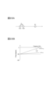
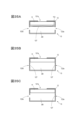
- Example 3-2 As illustrated in FIGS. 15A and 15B, the open end of the sound hole 123a (second sound hole) is directed toward the edge portion 112a of the other side 112 (D2 direction side) of the driver unit 11, and the sound hole 123a
- the structure may be such that a direct wave of the acoustic signal AC2 (second acoustic signal) emitted from the other side 112 of the driver unit 11 is mainly emitted from the driver unit 11.
- the wall portion 122 (area AR2) disposed on the other side of the driver unit 11 is not in contact with the driver unit 11 (does not contact while the driver unit 11 is being driven), and the driver unit 11 and the wall portion 122 disposed on the other side 112 of the driver unit 1 is 5 mm or less, and the acoustic signal AC2 (second acoustic signal) is mainly transmitted from the sound hole 123a (second sound hole). ) may be configured to emit direct waves.
- the region AR2 being out of contact with the driver unit 11 while the driver unit 11 is being driven means, for example, that the distance dis1 is larger than the amplitude on the other side 112 of the driver unit 11 during the drive.
- the housing 12 may be provided with a sound absorbing material that absorbs high frequency acoustic signals.
- This sound-absorbing material has a characteristic that the sound absorption coefficient for an acoustic signal of frequency f 1 is larger than the sound absorption coefficient for an acoustic signal of frequency f 2 .
- the frequency f 1 is higher than the frequency f 2 (f 1 >f 2 ).
- this sound absorbing material suppresses higher frequency components of the acoustic signal more than lower frequency components.
- the frequency f 1 is less than or equal to the predetermined frequency f2 th
- the frequency f 2 is greater than the predetermined frequency f2 th .
- the predetermined frequency f2 th examples are 3000Hz, 4000Hz, 5000Hz, 6000Hz, etc.
- Examples of such sound absorbing materials include paper such as Japanese paper and hanshi, nonwoven fabric, silk, and cotton.
- the sound absorbing material 13 may be provided in at least one of the sound holes 123a (second sound hole).
- the sound holes 123a may be filled with the sound absorbing material 13.
- At least one of the inside and outside of at least one of the sound holes 123a may be covered with the sound absorbing material 13.
- the sound absorbing material 13 may be provided in a region on the other side 112 (the D2 direction side) of the driver unit 11 inside the housing 12.
- the sound absorbing material 13 may be fixed to a region AR2 of the wall portion 122 located on the other side 112 (D2 direction side) of the driver unit 11.
- the sound absorbing material 13 may be fixed inside the wall portion 123.
- the sound absorbing material 13 is provided in at least one of the sound holes 123a (second sound hole), and the sound absorbing material 13 is provided in the area on the other side 112 (direction D2 side) of the driver unit 11 inside the housing 12. It may be.
- at least one of the sound holes 123a may be filled with the sound absorbing material 13, and the sound absorbing material 13 may be further fixed to the region AR2 of the wall portion 122.
- Position P1 is a position near the left ear 1120 of dummy head 1100 (near the acoustic signal output device 10), and position P2 is a position 15 cm outward from position P1.
- FIG. 17 illustrates the frequency characteristics of the acoustic signal observed at position P1 in FIG. 5B
- FIG. 18 illustrates the frequency characteristics of the acoustic signal observed at position P2 in FIG. 5B
- FIG. 19 illustrates the frequency characteristics of the acoustic signal observed at position P1 in FIG.
- the difference between the frequency characteristic of the acoustic signal observed at position P2 and the frequency characteristic of the acoustic signal observed at position P2 is illustrated.
- the horizontal axis shows frequency (Frequency [Hz])
- the vertical axis shows sound pressure level (SPL) [dB].
- the solid line graph illustrates the frequency characteristics when using the acoustic signal output device 10 in which the sound hole 123a is covered with a sound absorbent material (With acoustic absorbent), and the broken line graph illustrates the frequency characteristics when using the acoustic signal output device 10 of the first embodiment.
- the following is an example of the frequency characteristics when there is no acoustic absorbent. As illustrated in FIG. 19, in the frequency band of 2000 Hz or higher, the acoustic signal output device 10 with the sound hole 123a covered with a sound absorbing material is generally better than the acoustic signal output device 10 without the sound absorbing material.
- the difference in sound pressure between the acoustic signal observed at position P1 and the acoustic signal observed at position P2 is larger than when using This indicates that, in a frequency band of 2000 Hz or more, sound leakage at position P2 is generally more suppressed when the acoustic signal output device 10 in which the sound hole 123a is covered with a sound absorbing material is used.
- FIG. 20A an acoustic signal AC1 which is a sine wave is emitted from the sound hole 121a (first sound hole), and an opposite phase signal (phase inversion signal) of the acoustic signal AC1 is emitted from the sound hole 123a (second sound hole).
- An example of how the acoustic signal AC2 (second acoustic signal) is emitted is illustrated.
- the horizontal axis in FIG. 20A represents the phase (Phase [degree])
- the vertical axis represents the magnitude (eg, amplitude and power) of the acoustic signals AC1 and AC2.
- the sound hole 121a and the sound hole 123a are separated by a distance D pn .
- D pn is 1.5 cm.
- a portion of the acoustic signal AC1 emitted from the sound hole 121a is offset by a portion of the acoustic signal AC2 emitted from the sound hole 123a, thereby suppressing sound leakage of the acoustic signal AC1.
- the acoustic signals AC1 and AC2 have a phase difference based on the distance D pn .
- FIG. 20B shows the relationship between the phase difference and frequency when the distance D pn is 1.5 cm.
- phase difference Phase difference [degree]
- this phase difference becomes further away from 180° as the frequency becomes higher. Due to the influence of this phase difference, the acoustic signal AC1 emitted from the sound hole 121a and the acoustic signal AC2 emitted from the sound hole 123a do not have completely opposite phases.
- n is a positive integer.
- FIG. 20C shows the maximum value of the sum of the magnitudes of the acoustic signal AC1 and the acoustic signal AC2 observed at a position 15 cm outward from the acoustic signal output device when the distance D pn is 1.5 cm, and the corresponding The relationship between the frequencies of the acoustic signals AC1 and AC2 will be illustrated.
- the vertical axis represents the ratio of the maximum value of the sum of the magnitudes of the acoustic signal AC1 and the acoustic signal AC2 to the acoustic signal AC1.
- the ratio of the maximum value of the sum of the magnitudes of the acoustic signal AC1 and the acoustic signal AC2 to the acoustic signal AC1 exceeds 1 from around 3000 Hz, and the sound leakage is sufficiently suppressed. It turns out that it cannot be suppressed.
- the acoustic signal output device 10 is configured such that the length of the sound hole 121a (first sound hole) and the sound hole 123a (second sound hole) in the depth direction (duct length, for example, the sound hole 121a, 123a) is L [mm], the total opening area of the sound hole 121a (first sound hole) and sound hole 123a (second sound hole) is S [mm 2 ], and the depth of the housing 12 is It can be modeled as a Helmholtz resonator (enclosure) in which the volume of the internal space (for example, region AR) is V [mm 3 ].
- the resonance frequency f H [Hz] based on the Helmholtz resonance of the housing 12 modeled in this way is as follows.
- c is the sound speed
- S S 1 +...+S K
- K is the sound hole 121a, 123a.
- F is a function
- F(S) is a function value of S by the function F.
- FIG. 21B illustrates the relationship between the resonance frequency fH and the magnitude of the acoustic signal AC2 (negative phase signal) inside the housing 12.
- the horizontal axis in FIG. 21B represents the frequency (Frequency [Hz])
- the vertical axis represents the magnitude of the acoustic signal AC2 emitted from the driver unit 11 to the internal space (area AR) of the housing 12.
- the magnitude of the acoustic signal AC2 emitted from the driver unit 11 into the internal space of the housing 12 reaches a maximum at the resonance frequency fH .
- the phase of the acoustic signal AC2 emitted from the driver unit 11 into the internal space of the housing 12 changes significantly around the resonance frequency fH .
- FIG. 21C illustrates the relationship between the phase and frequency of the acoustic signal AC2 emitted from the driver unit 11 into the internal space of the housing 12.
- the horizontal axis in FIG. 21C represents the frequency (Frequency [Hz])
- the vertical axis represents the phase of the acoustic signal AC2 emitted from the driver unit 11 into the internal space of the housing 12 (from the driver unit 11 to the housing 12).
- FIG. 21C illustrates the relationship between the phase and frequency of the acoustic signal AC2 emitted from the driver unit 11 into the internal space of the housing 12.
- the horizontal axis in FIG. 21C represents the frequency (Frequency [Hz])
- the vertical axis represents the phase of
- the phase of the acoustic signal AC2 emitted from the driver unit 11 into the internal space of the housing 12 is delayed by 90° at the resonance frequency fH , and as the frequency becomes higher, the phase approaches the phase delayed by 180°.
- the resonance frequency f H [Hz] By controlling the resonance frequency f H [Hz] based on the Helmholtz resonance of the housing 12, the phase of the acoustic signal AC2 emitted to the outside from the sound hole 123a is adjusted, and sound leakage at a desired frequency is suppressed. .
- the acoustic signal AC1 emitted to one side (D1 direction side) of the driver unit 11 is emitted from the sound hole 121a to the outside of the acoustic signal output device 10, and a part of the acoustic signal AC1 is emitted to the outside of the acoustic signal output device 10. It reaches position P2 on the other side (direction D2 side) of the output device 10. Further, the acoustic signal AC2 emitted to the other side (direction D2) of the driver unit 11 is delayed in phase as described above based on the Helmholtz resonance of the housing 12, and is output from the sound hole 123a to the outside of the acoustic signal output device 10.
- the length L in the depth direction of the sound holes 121a and 123a, the total opening area S of the sound holes 121a and 123a, and the volume V of the internal space of the housing 12 are calculated.
- the phase of the acoustic signal AC2 emitted from the driver unit 11 into the internal space of the housing 12 can be adjusted.
- the phase difference between the acoustic signal AC1 and the acoustic signal AC2 at the position P2 can be brought close to 180°, and sound leakage can be sufficiently suppressed.
- FIG. 22B shows the phase difference and frequency between the acoustic signal AC1 and the acoustic signal AC2 at position P2 when the resonance frequency f H [Hz] based on Helmholtz resonance of the housing 12 with a distance D pn of 1.5 cm is adjusted.
- the following is an example of the relationship between
- the horizontal axis in FIG. 22B represents frequency (Frequency [Hz])
- the vertical axis represents phase difference (Phase difference [degree]).
- FIG. 22C illustrates the relationship between the maximum value of the sum of the magnitudes of the acoustic signal AC1 and the acoustic signal AC2 observed at the position P2 and the frequencies of the acoustic signals AC1 and AC2.
- the vertical axis represents the ratio of the maximum value of the sum of the magnitudes of the acoustic signal AC1 and the acoustic signal AC2 to the acoustic signal AC1.
- the maximum value of the sum of the magnitudes of the acoustic signal AC1 and the acoustic signal AC2 with respect to the acoustic signal AC1 can be made less than 1, and sound leakage can be sufficiently suppressed.
- the length L, the total opening area S, and the volume V ( The length L in the depth direction of the sound hole 121a and the sound hole 123a, the total opening area S of the sound hole 121a and the sound hole 123a, and the volume V of the internal space of the housing 12 are designed.
- phase difference (phase delay) ⁇ c for canceling the phase difference ⁇ Dpn is introduced into the acoustic signal AC2 emitted to the outside of the acoustic signal output device 10 .
- phase difference ⁇ c phase difference ⁇ c
- y Asin( ⁇ t- ⁇ init + ⁇ Dpn )+Asin( ⁇ t- ⁇ - ⁇ init + ⁇ c ) (4)
- the phase difference ⁇ c close to the phase difference ⁇ Dpn is achieved by adjusting the resonance frequency f H based on the Helmholtz resonance of the housing 12 by optimizing the length L, the total opening area S, and the volume V. It is introduced into the acoustic signal AC2 emitted to the outside of the acoustic signal output device 10.
- phase difference ⁇ c (with ⁇ c )
- the phase difference between the acoustic signal AC1 and the acoustic signal AC2 at position P2 can be changed to that without the phase difference ⁇ c
- the angle can be made closer to 180° than in the case (without ⁇ c ) (FIG. 23B). As a result, sound leakage can be sufficiently suppressed in this frequency band.
- the frequency domain signal of the acoustic signal AC1 emitted from one side (D1 direction side) of the driver unit 11 is S pos ( ⁇ )
- the acoustic signal AC2 emitted from the other side (D2 direction side) of the driver unit 11 is S pos ( ⁇ )
- the frequency domain signal of S neg ( ⁇ ) be S neg ( ⁇ ). In this case, the following relationship holds true.
- Y lis ( ⁇ ) H pos,out ( ⁇ )H pos,in ( ⁇ )S pos ( ⁇ )+H neg,out ( ⁇ )H neg,in ( ⁇ )S neg ( ⁇ ) (5)
- the frequency domain signal of the acoustic signal emitted by the sound source inside the driver unit 11 is S sou ( ⁇ )
- the transfer function of one side (D1 direction side) of the sound source inside the driver unit 11 is H pos,spk ( ⁇ )
- the transfer function of the other side (the D2 direction side) of the sound source inside the driver unit 11 is H neg,spk ( ⁇ ).
- H pos,spk ( ⁇ ) H neg,spk ( ⁇ ) holds at the frequency ⁇ at which sound leakage is to be suppressed, and that H pos,in ( ⁇ ) can be approximated to 1
- Equation (8 ) can be transformed as follows.
- H neg,in ( ⁇ ) H pos,out ( ⁇ )/H neg,out ( ⁇ ) (9)
- the phase characteristics of the transfer functions H pos,out ( ⁇ ) and H neg,out ( ⁇ ) can be regarded as linear. That is, the transfer functions H pos,out ( ⁇ ) and H neg,out ( ⁇ ) can be considered to depend only on the delay based on distance. In this case, as illustrated in FIG. 24B, the phase characteristic of H neg,in ( ⁇ ) in equation (9) can also be considered linear with respect to frequency ⁇ .
- the phase characteristic H neg,in ( ⁇ ) satisfies equation (9) or approaches the right-hand side of equation (9).
- H neg,in ( ⁇ ) matches or approximates H pos,out ( ⁇ )/H neg,out ( ⁇ ) (Equation (9)).
- the frequency ⁇ belongs to a predetermined frequency band of the audible frequency band.
- the predetermined frequency band is, for example, a frequency band in which sound leakage at position P2 is to be suppressed.
- Design condition 1 Position when acoustic signal AC1 (first acoustic signal) is emitted from sound hole 121a (first sound hole) and acoustic signal AC2 (second acoustic signal) is emitted from sound hole 123a (second sound hole)
- the sound pressure level of the acoustic signal AC1 (first acoustic signal) at P2 (second point) is that the acoustic signal AC1 (first acoustic signal) is emitted from the sound hole 121a (first sound hole)
- the sound pressure level of the acoustic signal AC1 (first acoustic signal) at position P2 (second point) when the acoustic signal AC2 (second acoustic signal) is not emitted from the hole 123a (second sound hole) small (e.g., equations (10a) and (11a)).
- Design condition 2 Position when acoustic signal AC1 (first acoustic signal) is emitted from sound hole 121a (first sound hole) and acoustic signal AC2 (second acoustic signal) is emitted from sound hole 123a (second sound hole)
- the sound pressure level of the acoustic signal AC1 (first acoustic signal) at P2 (second point) is that the acoustic signal AC1 (first acoustic signal) is not emitted from the sound hole 121a (first sound hole)
- the sound pressure level of the acoustic signal AC1 (first acoustic signal) at position P2 (second point) when the acoustic signal AC2 (second acoustic signal) is emitted from the hole 123a (second sound hole) e.g., equation (10b)
- the resonance frequency based on the Helmholtz resonance of the housing 12 belongs to a frequency band of 3000 Hz or more and 8000 Hz or less.
- the acoustic signal output device 10 will be illustrated below. However, these are examples and do not limit the invention.
- FIG. 25A shows a design example in which a cylindrical duct 123aa for adjusting L is further provided in the sound hole 123a provided in the housing 12 of the acoustic signal output device 10.
- the duct 123aa in FIG. 25A extends inward from the sound hole 123a, thereby adjusting the length L of the sound hole 123a in the depth direction.
- FIG. 25B shows another design example in which a cylindrical duct 123aa for adjusting L is further provided in the sound hole 123a provided in the housing 12 of the acoustic signal output device 10.
- the difference from the example in FIG. 25A is that the duct 123aa extends from the sound hole 123a toward the inside and outside of the housing 12. Even in this case, the length L of the sound hole 123a in the depth direction can be adjusted.
- FIG. 25C shows a design example in which an additional member 124 is provided in the area AR inside the housing 12 of the acoustic signal output device 10. By adjusting the volume of the additional member 124, the volume V of the internal space (area AR) of the housing 12 can be adjusted.
- FIG. 26A shows a design example in which a cylindrical duct 121aa for adjusting L is provided in the sound hole 121a provided in the housing 12 of the acoustic signal output device 10.
- the duct 121aa in FIG. 26A extends inward from the sound hole 121a, thereby adjusting the length L of the sound hole 121a in the depth direction.
- the design example in FIG. 26B also has a cylindrical duct 121aa for adjusting L in the sound hole 121a provided in the housing 12 of the acoustic signal output device 10.
- the difference from the example in FIG. 26A is that the sound hole 121a is provided at a position offset from the center of the acoustic signal output device 10, and the inner diameter of the duct 121aa is tapered from the inside of the housing 12 toward the outside. and that the duct 121aa extends from the sound hole 121a toward the inside and outside of the housing 12. Even in this case, the length L in the depth direction of the sound hole 121a can be adjusted.
- FIG. 26C shows a design example in which not only the sound hole 121a but also the sound hole 123a is provided on the D1 direction side of the driver unit 11 of the acoustic signal output device 10. In this way, the arrangement of the sound holes 123a is changed, the distance between the sound holes 121a and the sound holes 123a is adjusted, and the volume V of the internal space of the housing 12 is also adjusted.
- FIG. 27A a design in which the sound hole 121a is provided not on the D1 direction side of the driver unit 11 (the emission direction side of the acoustic signal AC1) but on the D6 direction side that is perpendicular to the D1 direction, and the sound hole 123a is also provided on the same D6 direction side.
- the distance between the sound hole 121a and the sound hole 123a is adjusted, and the volume V of the internal space of the housing 12 is also adjusted.
- FIG. 27B is a design example in which, in addition to the configuration shown in FIG. 27A, a sound hole 123a is also provided on the D2 direction side. Thereby, the distance between the sound hole 121a and the sound hole 123a can be further adjusted.
- FIG. 27C is a design example in which, in addition to the configuration shown in FIG. 27B, a cylindrical duct 121aa is further provided in the sound hole 123a provided on the D2 direction side. Thereby, the length L in the depth direction of the sound hole 123a provided on the D2 direction side can be further adjusted.
- FIG. 28A shows a design example in which a cylindrical horn 121ab that enhances the directivity of the acoustic signal AC1 emitted from the sound hole 121a in the D1 direction is provided at the opening of the sound hole 121a of the housing 12.
- the inner diameter of the horn 121ab widens in a tapered manner from the inside of the housing 12 toward the outside.
- the outer side (D1 direction side) of the horn 121ab is placed toward the right ear 1010 of the user 1000.
- This horn 121ab can suppress the acoustic signal AC1 from going around to the position P2, and also adjust the phase difference between the acoustic signal AC1 emitted from the sound hole 121a and the acoustic signal AC2 emitted from the sound hole 123a. Furthermore, the length L of the sound hole 121a in the depth direction is also adjusted by the horn 121ab.
- FIG. 29A is a modification of the structure shown in FIG. 28A, and is a design example in which a sound hole 121aba is provided on the side surface of the horn 121ab.
- the higher the frequency component the higher the straightness. Therefore, the higher frequency component of the acoustic signal AC1 is less likely to be emitted from the sound hole 121aba on the side of the horn 121ab, and the lower frequency component is also more likely to be emitted from the sound hole 121aba.
- the phase difference between the acoustic signal AC1 and the acoustic signal AC2 at the position P2 can be adjusted according to the frequency.
- FIG. 29B is a modification of FIG. 29A, and has a design in which a sound hole 121aba provided on the side surface of the horn 121ab and a sound hole 123a provided in the housing 12 are provided with a sound absorbing material 13 that absorbs high frequency acoustic signals.
- a sound hole 121aba provided on the side surface of the horn 121ab and a sound hole 123a provided in the housing 12 are provided with a sound absorbing material 13 that absorbs high frequency acoustic signals.
- ⁇ Design example 13> 30A is also a modification of FIG. 28A, in which not only the sound hole 121a but also the sound hole 123a is provided on the D1 direction side of the driver unit 11 of the acoustic signal output device 10, and the horn 121ab is provided on the outside of the sound hole 121a of the housing 12.
- a cylindrical horn 123ab surrounding the outside of the horn 121ab is also provided. The inner diameter of the horn 123ab tapers outward from the inside of the housing 12, and the horn 121ab is disposed inside the horn 123ab.
- the opening of the sound hole 123a is arranged in the region between the horn 123ab and the horn 121ab (the region outside the horn 123ab and inside the horn 121ab).
- the acoustic signal AC2 emitted to the outside from the sound hole 123a is emitted to the outside through the gap 123aba between the horns 123ab and 121ab.
- These horns 123ab, 121ab suppress the acoustic signals AC1, AC2 from going around to the above-mentioned position P2, and also reduce the position of the acoustic signal AC1 emitted from the sound hole 121a and the acoustic signal AC2 emitted from the sound hole 123a.
- Phase difference can also be adjusted.
- the length L in the depth direction of the sound holes 121a, 123a is also adjusted by the horns 121ab, 123ab.
- FIG. 30B is a modification of FIG. 27A, in which the sound hole 121a is provided not on the D1 direction side of the driver unit 11 (the acoustic signal AC1 emission direction side) but on the D6 direction side that is perpendicular to the D1 direction, and the sound hole 123a is also the same. It is provided on the D6 direction side. Furthermore, in the design example shown in FIG.
- a cylindrical horn 121ab that increases the directivity of the acoustic signal AC1 emitted from the sound hole 121a in the D6 direction is provided at the opening of the sound hole 121a of the housing 12, and A cylindrical horn 123ac is provided at the opening of the sound hole 123a of the housing 12 to enhance the directivity of the acoustic signal AC2 emitted in the direction.
- These horns 121ab and 123ac suppress the acoustic signals AC1 and AC2 from going around to the above-mentioned position P2, and also reduce the position of the acoustic signal AC1 emitted from the sound hole 121a and the acoustic signal AC2 emitted from the sound hole 123a. Phase difference can also be adjusted.
- the length L in the depth direction of the sound holes 121a, 123a is also adjusted by the horns 121ab, 123ac.
- FIG. 31A illustrates the frequency characteristic of the acoustic signal observed at position P1 in FIG. 5B
- FIG. 31B illustrates the frequency characteristic of the acoustic signal observed at position P2 in FIG. 5B
- FIG. 31C This figure illustrates the difference between the frequency characteristics of the acoustic signal observed at position P1 and the frequency characteristics of the acoustic signal observed at position P2 (difference in sound pressure level of each frequency).
- the horizontal axis shows frequency (Frequency [Hz]), and the vertical axis shows sound pressure level (SPL) [dB].
- each of the acoustic signal output devices 10 includes one sound hole 121a and four sound holes 123a.
- “standard” refers to the acoustic signal output device 10 in which the total opening area of the four sound holes 123a is 56 mm2
- "0.5 times", “0.75 times”, “1.25 times”, and “1.5 times” refer to the four sound holes 123a.
- the acoustic signal output device 10 is shown in which the total opening area of the sound holes 123a is 0.5 times, 0.75 times, 1.25 times, and 1.5 times, respectively, 56 mm 2 .
- the frequency characteristics of the difference between the sound pressure of the acoustic signal observed at position P1 and the acoustic signal observed at position P2 also differ, and The sound leakage suppression performance at P2 is also different.
- the sound leakage is minimal at frequencies slightly higher than the respective resonance frequencies fH , and this is due to the relationship illustrated in FIG. 22C. It matches.
- FIG. 32A illustrates the frequency characteristics of the acoustic signal observed at position P1 in FIG. 5B
- FIG. 32B illustrates the frequency characteristics of the acoustic signal observed at position P2 in FIG. 5B
- FIG. 32C This figure illustrates the difference between the frequency characteristics of the acoustic signal observed at position P1 and the frequency characteristics of the acoustic signal observed at position P2 (difference in sound pressure level of each frequency).
- the horizontal axis shows frequency (Frequency [Hz]), and the vertical axis shows sound pressure level (SPL) [dB].
- acoustic signal output devices 10 having different volumes V due to different heights of the additional member 124 illustrated in FIG. 25C were evaluated.
- standard refers to the acoustic signal output device 10 in which the height of the additional member 124 is the standard value
- “height +1.0 mm” and “height +2.0 mm” respectively refer to the height of the additional member 124.
- F(S) S 1/2
- the resonance frequency f H of the housing 12 of the "standard”, "height +1.0 mm", and "height +2.0 mm” acoustic signal output device 10 determined according to formula (1) [Hz] is as follows.
- the frequency characteristics of the acoustic signal observed at position P1 and the acoustic signal observed at position P2 differ due to the difference in the volume V of the internal space of the housing 12.
- the frequency characteristics of the difference in sound pressure between the acoustic signal observed at position P1 and the acoustic signal observed at position P2 are determined.
- the performance of suppressing sound leakage at position P2 is also different. For example, in the "standard” and "height +1.0 mm" acoustic signal output devices 10, sound leakage is minimal at frequencies slightly higher than the respective resonance frequencies fH , and this is consistent with the relationship illustrated in FIG. 22C. It matches.
- the frequency characteristics of the acoustic signal output device 10 of the embodiment reference: with an enclosure, which is the area AR surrounded by the walls 122 and 123) and the open type (no enclosure) acoustic signal output device are illustrated. Note that in the open type acoustic signal output device, the wall portion 122 on the D1 direction side of the driver unit 11 of the acoustic signal output device 10 does not exist, and the area AR is open in the D2 direction.
- 33A illustrates the frequency characteristics of the acoustic signal observed at position P1 in FIG. 5B
- FIG. 33B illustrates the frequency characteristics of the acoustic signal observed at position P2 in FIG. 5B
- FIG. 33C This figure illustrates the difference between the frequency characteristics of the acoustic signal observed at position P1 and the frequency characteristics of the acoustic signal observed at position P2 (difference in sound pressure level of each frequency).
- the horizontal axis shows frequency (Frequency [Hz]), and the vertical axis shows sound pressure level (SPL) [dB].
- the frequency characteristics of the acoustic signal observed at position P1 and the acoustic signal observed at position P2 differ depending on the presence or absence of an enclosure.
- the acoustic signal output device 10 of the embodiment having an enclosure can suppress sound leakage at position P2 in a wide frequency band compared to the acoustic signal output device without an enclosure. I know that there is.
- the phase of the acoustic signal AC2 emitted from the driver unit 11 to the internal space of the housing 12 can be adjusted. , it can be seen that sound leakage in a desired frequency band can be sufficiently suppressed.
- phase relationship between the acoustic signal AC1 emitted from the sound hole 121a and the acoustic signal AC2 emitted from the sound hole 123a is adjusted by controlling the resonance frequency based on Helmholtz resonance. did.
- a waveguide (acoustic signal waveguide path) is provided to adjust at least one of the path length of the signal) to the emission position to the outside of the acoustic signal output device 10, and thereby the phase relationship can be adjusted. good.
- the above-mentioned waveguide may be designed so as to satisfy any of Examples 1 to 6 of the above-mentioned conditions. Furthermore, when adjusting the phase relationship between the acoustic signal AC1 emitted from the sound hole 121a and the acoustic signal AC2 emitted from the sound hole 123a by the waveguide, the influence of the resonant frequency based on the Helmholtz resonance of the housing 12 is small. Even if the length L in the depth direction of the sound hole 121a and the sound hole 123a, the total opening area S of the sound hole 121a and the sound hole 123a, and the volume V of the internal space of the housing 12 are designed so that good.
- the resonant frequency based on the Helmholtz resonance of the housing 12 belongs to a frequency band other than the predetermined frequency band within the audible frequency band (for example, a frequency band other than 3000 Hz or more and 8000 Hz or less; for example, a frequency band higher than 8000 Hz).
- the length L in the depth direction of the sound hole 121a and the sound hole 123a, the total opening area S of the sound hole 121a and the sound hole 123a, and the volume V of the internal space of the housing 12 may be designed as follows. .
- the phase relationship between the acoustic signal AC1 emitted from the sound hole 121a and the acoustic signal AC2 emitted from the sound hole 123a is adjusted by both the waveguide and the resonance frequency based on Helmholtz resonance of the housing 12. Good too.
- the resonant frequency based on the Helmholtz resonance of the housing 12 is adjusted in the depth direction of the sound holes 121a and 123a so that it belongs to a predetermined frequency band within the audible frequency band (for example, a band of 3000 Hz or more and 8000 Hz or less).
- the length L, the total opening area S of the sound holes 121a and 123a, and the volume V of the internal space of the housing 12 may be designed.
- the configuration of the acoustic signal output device 10 provided with the above-mentioned waveguide will be illustrated. However, these are examples and do not limit the invention.
- FIG. 34A shows a position where the acoustic signal AC2 (second acoustic signal) is released from the driver unit 11 to the outside of the acoustic signal output device 10 in the D2 direction side of the driver unit 11 in the housing 12 of the acoustic signal output device 10.
- a design example is shown in which waveguides 125 and 126 are provided to adjust the path length.
- the waveguides 125 and 126 are hollow paths (for example, acoustic tubes), and one of them is arranged on the D2 direction side of the driver unit 11, and the other is arranged on the opening side of the sound hole 123a.
- the acoustic signal AC2 emitted in the direction D2 of the driver unit 11 is emitted to the outside from the sound hole 123a via the waveguides 125 and 126.
- the acoustic signal AC1 first acoustic signal
- the acoustic signal AC2 second acoustic signal
- a part of the waveguide may be placed outside the housing 12.
- the tip portion 125a of the waveguide 125 is placed outside the housing 12.
- a horn 121ab functioning as a waveguide is provided on the D1 direction side of the driver unit 11 of the acoustic signal output device 10, and a driver unit is provided on the D2 direction side of the driver unit 11 in the housing 12 of the acoustic signal output device 10.
- a design example is shown in which waveguides 125 and 126 are provided for adjusting the path length from the position No. 11 to the emission position of the acoustic signal AC2 (second acoustic signal) to the outside of the acoustic signal output device 10.
- the waveguide is not limited to an acoustic tube or a horn, and the length of the path from the position of the driver unit 11 to the position at which the acoustic signal AC1 is emitted to the outside of the acoustic signal output device 11 and/or the length of the path from the position of the driver unit 11 Any mechanical configuration may be used as long as it can adjust at least one of the path length from the position of AC2 to the position where the acoustic signal AC2 is released to the outside of the acoustic signal output device 10.
- the phase relationship between the acoustic signal AC1 emitted from the sound hole 121a and the acoustic signal AC2 emitted from the sound hole 123a is adjusted by controlling the resonance frequency based on Helmholtz resonance. did.
- the housing 12 is provided with a vibrating body whose resonance frequency belongs to a predetermined frequency band within the audible frequency band on the path to the position P2 (on the D2 direction side), thereby controlling the phase relationship. May be adjusted.
- the above-mentioned vibrating body may be designed so as to satisfy any of Condition Examples 1 to 6 described in Modification 5 of the first embodiment.
- the resonant frequency of the above-mentioned vibrating body may belong to a frequency band of 3000 Hz or more and 8000 Hz or less.
- the configuration of the acoustic signal output device 10 provided with the above-mentioned vibrating body will be illustrated. However, these are examples and do not limit the invention.
- FIG. 35A shows a design example in which a vibrating membrane 127 is provided as a vibrating body in the region AR inside the housing 12 of the acoustic signal output device 10.
- the diaphragm 127 is connected to the other side 112 (D2 direction side) of the acoustic signal output device 10, which becomes the path of the acoustic signal AC2 emitted to the other side 112 (D2 direction side) of the driver unit 11, and the sound hole 123a. placed between.
- the acoustic signal AC2 emitted in the direction D2 of the driver unit 11 is emitted to the outside from the sound hole 123a via the above-mentioned path.
- the vibrating membrane 127 By providing the vibrating membrane 127 on this path, the acoustic signal AC1 (first acoustic signal) emitted from the D1 side of the driver unit 11 and externally from the sound hole 121a and the vibrating membrane 127 are arranged.
- the phase difference at the position P2 with the acoustic signal AC2 (second acoustic signal) emitted to the outside from the sound hole 123a via the path can be adjusted. As a result, sound leakage at a desired frequency can be sufficiently suppressed at position P2.
- the vibrating membrane 127 may be placed in the sound hole 123a.
- the vibrating membrane 127 is arranged in all the sound holes 123a.
- a vibrating membrane 127 may be placed in some of the sound holes 123a.
- the vibrating membrane 127 may have air holes.
- the vibrating membrane 127 can be a thin membrane made of PET (polyethylene terephthalate), for example. Further, the vibrating body is not limited to a vibrating membrane, and any vibrating body that can receive sound of a specific frequency and cause resonance may be used. For example, a tuning fork can be used.
- FIG. 37A illustrates the sound pressure level at position P2 of the acoustic signal AC1 at each frequency
- FIG. 37B illustrates the sound pressure level at position P2 of the acoustic signal AC2 at each frequency
- FIG. 37C is an example of the sound pressure level at position P2 of the acoustic signal obtained by canceling the acoustic signal AC1 at each frequency with the acoustic signal AC2.
- the horizontal axis shows frequency (Frequency [Hz]), and the vertical axis shows sound pressure level (SPL) [dB]. From these figures, it can be seen that by changing the thickness of the diaphragm, the frequency characteristics of sound leakage at position P2 change.
- FIG. 38A illustrates the sound pressure level of the acoustic signal AC1 at each frequency
- FIG. 38B illustrates the sound pressure level of the acoustic signal AC2 at each frequency
- FIG. 38C illustrates the sound pressure level of the acoustic signal AC1 at each frequency.
- This is an example of the sound pressure level of the acoustic signal canceled by the acoustic signal AC2.
- the horizontal axis shows frequency (Frequency [Hz]), and the vertical axis shows sound pressure level (SPL) [dB].
- FIG. 39A illustrates the phase of the acoustic signal AC1 at each frequency
- FIG. 39B illustrates the phase of the acoustic signal AC2 at each frequency
- FIG. 39C illustrates the phase of the acoustic signal AC1 at each frequency with the acoustic signal AC2.
- the horizontal axis shows frequency (Frequency [Hz])
- the vertical axis shows phase (Phase [degree]). From these figures, it can be seen that by changing the thickness of the diaphragm, the resonant frequency of the membrane changes and the frequency at which the phase of the acoustic signal is inverted changes.
- the size of the driver unit 11 may have to be increased.
- the size and weight of the acoustic signal output device 10 itself also increases.
- mounting the acoustic signal output device 10, which is large in size and weight, near the ear canal increases the burden on the ears and the sensation of a foreign body. Therefore, the casing provided with the sound hole and the driver unit 11 may be separated and connected by a waveguide. This makes it possible to increase the size of the driver unit 11 without increasing the size or weight of the casing that is attached near the ear canal. This will be explained in detail below.
- the acoustic signal output device 20 of this embodiment is also an acoustic listening device that is worn without sealing the user's ear canal.
- the acoustic signal output device 20 of this embodiment includes a driver unit 11, a casing 22 having hollow parts AR21 and AR22 (first and second hollow parts), and a housing 22 with the driver unit 11 inside.
- the housing 23 is housed, hollow waveguides 24 and 25 (first and second waveguides) that connect the housings 22 and 23, and the waveguides 24 and 25 are connected to the housing 22. It has hollow joining members 26 and 27.
- the driver unit 11 emits an acoustic signal AC1 (first acoustic signal) based on the input output signal to one side (direction D3), and outputs an inverse phase signal or an inverse signal of the acoustic signal AC1.
- This is a device that emits an acoustic signal AC2 (second acoustic signal) which is an approximate signal of the phase signal to the other side (direction D4 side).
- the configuration of the driver unit 11 is the same as the first embodiment except that the D1 direction is replaced with the D3 direction and the D2 direction is replaced with the D4 direction.
- the housing 23 is a hollow member having a wall portion on the outside, and houses the driver unit 11 inside.
- the shape of the casing 23 it is desirable that the shape of the casing 23 be rotationally symmetrical (line symmetrical) or substantially rotationally symmetrical about the axis A2 extending along the D3 direction.
- the housing 23 has a substantially cylindrical shape with both end surfaces.
- the casing 23 may have a substantially dome shape with a wall at the end, a hollow substantially cubic shape, or any other three-dimensional shape.
- One end 241 of the waveguide 24 is attached to a wall portion 231 of the housing 23 disposed on the surface 111 side on one side (the D3 direction side) of the driver unit 11.
- the waveguide 24 (first waveguide) whose one end 241 is connected to one side (D3 direction side) of the driver unit 11 in this way emits light from the surface 111 of the driver unit 11 to one side (D3 direction side).
- the generated acoustic signal AC1 is led out to the outside of the housing 23.
- One end 251 of the waveguide 25 is attached to a wall portion 232 of the casing 23 disposed on the other side (D4 direction side) side of the surface 112 of the driver unit 11 .
- the waveguide 25 (second waveguide) whose one end 251 is connected to the other side (D4 direction side) of the driver unit 11 emits light from the surface 112 of the driver unit 11 to the other side (D4 direction side).
- the generated acoustic signal AC2 is led out to the outside of the housing 23.
- the housing 23 may be made of a rigid body such as synthetic resin or metal, or may be made of an elastic body such as rubber.
- the waveguides 24 and 25 are, for example, hollow members configured in a tube shape, and transmit acoustic signals AC1 and AC2 input from one end 241 and 251 to the other end 242 and 252 and discharged from the other ends 242, 252.
- the waveguides 24 and 25 are not limited to tube-shaped ones, and the acoustic signals collected at one end 241, 251 (first position) are transferred to the other end different from the one end 241, 251 (first position). Any structure may be used as long as it leads to 242, 252 (second position).
- the lengths of the waveguides 24 and 25 are not limited, preferably, the length of the sound path of the waveguide 24 and the length of the sound path of the waveguide 25 are equal, or the length of the sound path of the waveguide 24 is It is desirable that the difference between the length and the length of the acoustic path of the waveguide 25 is an integral multiple of the wavelength of the acoustic signals AC1 and AC2.
- the length of the sound path of the waveguide 24 (first waveguide) is L1
- the length of the sound path of the waveguide 25 (second waveguide) is L2
- n is an integer
- acoustic signal AC1 first acoustic signal
- the acoustic signal AC2 second acoustic signal
- the waveguides 24 and 25 may be made of a rigid body such as synthetic resin or metal, or may be made of an elastic body such as rubber.
- the joining member 26 has an open end 261 located on one side, a wall portion 262 which is a bottom surface located on the other side of the open end 261, and a space between the open end 261 and the wall portion 263 with the axis A1 as the center. It is a hollow member having a wall portion 263, which is a side surface surrounding the.
- the axis A1 of this embodiment passes through the open end 261 and the wall portion 263.
- axis A1 is perpendicular or substantially perpendicular to wall portion 262.
- the joining member 26 is rotationally symmetrical with respect to the axis A1.
- the wall portion 263 has a cylindrical shape, but the wall portion 263 may have other shapes such as a prismatic shape.
- the other end 242 of the waveguide 24 is attached to the wall 263, and the acoustic signal AC1 emitted from the other end 242 of the waveguide 24 is transmitted to the inside of the joining member 26 (between the open end 261 and the wall 263). the space between).
- the acoustic signal AC1 introduced into the interior of the joining member 26 is emitted from the open end 261.
- the joining member 26 may be made of a rigid body such as synthetic resin or metal, or may be made of an elastic body such as rubber.
- the joining member 27 has an open end 271 located on one side, a wall portion 272 which is a bottom surface located on the other side of the open end 271, and a space between the open end 271 and the wall portion 273 that It is a hollow member having a wall portion 273 which is a side surface surrounding A1.
- the axis A1 of this embodiment passes through the open end 271 and the wall portion 273.
- axis A1 is perpendicular or substantially perpendicular to wall portion 272.
- the joining member 27 is rotationally symmetrical with respect to the axis A1.
- the wall portion 273 has a cylindrical shape, but the wall portion 273 may have other shapes such as a prismatic shape.
- the other end 252 of the waveguide 25 is attached to the wall 273, and the acoustic signal AC2 emitted from the other end 252 of the waveguide 25 is transmitted to the inside of the joining member 27 (between the open end 271 and the wall 273). (the space between).
- the acoustic signal AC2 introduced into the interior of the joining member 27 is emitted from the open end 271.
- the joining member 27 may be made of a rigid body such as synthetic resin or metal, or may be made of an elastic body such as rubber.
- FIG. 41A-FIG. 41C, FIG. 42A, and FIG. a wall 223 that surrounds the space between the walls 221 and 222; and a hollow space that defines the space surrounded by the walls 221, 222, and 223. It has a wall portion 224 that separates the hollow portion AR21 (first hollow portion) and the hollow portion AR22 (second hollow portion).
- the hollow part AR21 and the hollow part AR22 are arranged on the same axis line A1 extending in the same direction D1.
- the central region of the hollow part AR21 and the central region of the hollow part AR22 are arranged on the same axis line A1. It is located. It is desirable that the internal space of the hollow part AR21 is separated from the internal space of the hollow part AR22 by the wall part 224.
- a joining member 26 to which the other end 242 of the waveguide 24 is attached is fixed or integrated on the inner wall of the hollow part AR21, and the open end 261 side of the joining member 26 is directed toward the wall 221 side.
- the wall portion 262 side of the joining member 26 is fixed or integrated with the wall portion 224 inside the hollow portion AR21, and the open end 261 side is directed toward the wall portion 221 side.
- the center of the wall portion 262 and the open end 261 of the joining member 26 is arranged on the axis A1.
- the other end 242 of the waveguide 24 is connected to the hollow part AR21 via the joining member 26, and the acoustic signal AC1 sent to the joining member 26 is transmitted from the open end 261 to the wall portion 221 side (direction D1 side). released towards. That is, for example, the joining member 26 is arranged on the axis A1, the open end 261 of the joining member 26 is open in the direction D1 (first direction) along the axis A1, and the other end of the waveguide 24 The acoustic signal AC1 introduced from 242 is emitted toward the direction D1 inside the hollow portion AR21.
- a through hole 222a is provided in the wall portion 222 of the hollow portion AR22.
- the through hole 222a is preferably arranged on the axis A1, and more preferably, the center of the through hole 222a is arranged on the axis A1.
- the open part of the through hole 222a is rotationally symmetrical with respect to the axis A1, and more preferably, the edge of the open part of the through hole 222a is circular. It is desirable that there be.
- a joining member 27 to which the other end 252 of the waveguide 25 is attached is fixed or integrated on the outside of the wall portion 222 of the housing 22, and the open end 271 side of the joining member 27 is directed toward the through hole 222a.
- the wall portion 272, the open end 271, and the center of the through hole 222a of the joining member 27 are arranged on the axis A1.
- the other end 252 of the waveguide 25 is connected to the hollow part AR22 via the joining member 27, and the acoustic signal AC2 sent to the joining member 27 is emitted from the open end 271 toward the internal space of the hollow part AR22. be done.
- the acoustic signal AC2 is emitted from the open end 271 toward the wall portion 224 side (the D1 direction side). That is, for example, the joining member 27 is arranged on the axis A1, the open end 271 of the joining member 27 is open in the direction D1 (first direction) along the axis A1, and the other end of the waveguide 25 The acoustic signal AC2 introduced from 252 is emitted toward the direction D1 inside the hollow portion AR22.
- the shape of the casing 22 is a substantially cylindrical shape having walls 221 and 222 as both end surfaces and a wall 223 as a side surface.
- the wall portions 221, 222, and 224 are perpendicular or substantially perpendicular to the axis A1, and the wall portion 223 is parallel or substantially parallel to the axis A1.
- the external shape of the casing 22 may be a substantially dome shape with a wall at the end, a hollow substantially cubic shape, or any other three-dimensional shape.
- the housing 22 may be made of a rigid body such as synthetic resin or metal, or may be made of an elastic body such as rubber.
- the wall portion 221 of the hollow portion AR21 (first hollow portion) is provided with an acoustic signal AC1 (first acoustic signal) introduced into the hollow portion AR21 by the waveguide 24 (first waveguide) and guided to the outside.
- a sound hole 221a (first sound hole) is provided.
- the acoustic signal AC2 (second acoustic signal) introduced into the interior of the hollow portion AR22 by the waveguide 25 (second waveguide) is transferred to the wall portion 223 of the hollow portion AR22 (second hollow portion).
- a second sound hole 221a (second sound hole) is provided.
- the sound hole 221a and the sound hole 223a are, for example, through holes penetrating the wall of the housing 12, but this does not limit the present invention. do not have.
- the sound hole 221a and the sound hole 223a do not need to be through holes as long as the acoustic signal AC1 and the acoustic signal AC2 can be respectively guided to the outside.
- the acoustic signal AC1 emitted from the sound hole 221a reaches the user's ear canal and is heard by the user.
- the sound hole 223a emits an acoustic signal AC2 which is an antiphase signal of the acoustic signal AC1 or an approximation signal of the antiphase signal.
- a part of this acoustic signal AC2 cancels out a part (sound leakage component) of the acoustic signal AC1 emitted from the sound hole 221a. Thereby, sound leakage can be suppressed.
- the arrangement configuration of the sound holes 221a and 223a is illustrated.
- the sound hole 221a (first sound hole) of this embodiment is provided in the wall portion 221 of the hollow portion AR21 disposed on one side of the joining member 26 (the side in the D1 direction, which is the side from which the acoustic signal AC1 is emitted).
- the sound hole 223a (second sound hole) of this embodiment is provided in the wall portion 223 that is in contact with the hollow portion AR22.
- the sound hole 221a (first The sound hole 223a (second sound hole) is provided on the D1 direction side (first direction side) of the housing 22, and the sound hole 223a (second sound hole) is provided on the D12 direction side (second direction side) of the housing 22. It is being That is, the sound hole 221a is opened facing in the D1 direction (first direction) along the axis A1, and the sound hole 223a is opened facing in the D12 direction (second direction).
- the outer shape of the casing 22 is a first end surface that is a wall portion 221 arranged on one side (the D1 direction side) of the joining member 26, and a wall section 221 that is the wall part 221 arranged on the other side (the D2 direction side) of the joining member 26.
- the space sandwiched between the second end surface, which is the part 222, and the first end surface and the second end surface is defined by an axis A1 along the emission direction (D1 direction) of the acoustic signal AC1 passing through the first end surface and the second end surface.
- the center has a side surface that is a surrounding wall portion 223 (FIGS.
- the sound hole 221a (first sound hole) is provided on the first end surface
- the sound hole 223a (second sound hole) is provided on the first end surface. It is located on the side. Further, in this embodiment, no sound hole is provided on the wall portion 222 side of the housing 22. If a sound hole is provided on the wall 222 side of the housing 22, the sound pressure level of the acoustic signal AC2 emitted from the housing 22 will exceed the level required to cancel out the sound leakage component of the acoustic signal AC1. This is because the excess amount is perceived as sound leakage.
- the sound hole 221a of this embodiment is arranged on or near the axis A1 along the emission direction (D1 direction) of the acoustic signal AC1.
- the axis A1 of this embodiment passes through the center of a region of the wall portion 221 disposed on one side (the D1 direction side) of the joining member 26 or near the center.
- the axis A1 is an axis that passes through the central region of the housing 22 and extends in the D1 direction. That is, the sound hole 221a of this embodiment is provided at the center of the area of the wall portion 221 of the housing 22.
- the shape of the edge of the open end of the sound hole 221a is circular (the open end is circular).
- the shape of the edge of the open end of the sound hole 221a may be any other shape such as an ellipse, a square, or a triangle.
- the open end of the sound hole 221a may have a mesh shape.
- the open end of the sound hole 221a may be composed of a plurality of holes.
- one sound hole 221a is provided in the wall portion 221 of the housing 22.
- two or more sound holes 221a may be provided in the wall portion 221 of the housing 22.
- the sound hole 223a (second sound hole) of this embodiment has an axis A1 along the emission direction of the acoustic signal AC1 (first acoustic signal). A plurality of them are provided along the circumference C1 centered at .
- an example is shown in which a plurality of sound holes 223a are provided on the circumference C1.
- the plurality of sound holes 223a are provided along the circumference C1, and it is not necessary that all the sound holes 223a are arranged strictly on the circumference C1.
- the sound hole 223a is provided along a first arc region that is any of the unit arc regions.
- the total opening area of the sound holes 223a is the opening area of the sound holes 223a (second sound holes) provided along the second arc area which is any unit arc area excluding the first arc area. is the same or approximately the same as the sum of (FIG. 42B).
- the plurality of sound holes 223a have the same shape, the same size, and are provided at the same intervals along the circumference C1.
- this does not limit the invention.
- the shape of the edge of the open end of the sound hole 223a is a square, but this does not limit the present invention.
- the shape of the edge of the open end of the sound hole 223a may be a circle, an ellipse, a triangle, or other shapes.
- the open end of the sound hole 223a may have a mesh shape.
- the open end of the sound hole 223a may be composed of a plurality of holes.
- there is no limit to the number of sound holes 223a and a single sound hole 223a or a plurality of sound holes 223a may be provided in the wall portion 223 of the housing 22.
- the ratio S 2 / S 1 of the total opening area of the sound holes 223a (second sound hole) to the total opening area S 1 of the sound holes 221a (first sound hole) is 2 / It is desirable to satisfy 3 ⁇ S 2 /S 1 ⁇ 4.
- the outer shape of the casing 22 is such that the first end surface is a wall portion 221 disposed on one side (the D1 direction side) of the joining member 26, and the wall portion 221 is the wall portion 221 disposed on the other side (the D2 direction side) of the joining member 26.
- the space sandwiched between the second end surface, which is the part 222, and the first end surface and the second end surface is defined by an axis A1 along the emission direction (D1 direction) of the acoustic signal AC1 passing through the first end surface and the second end surface.
- the ratio S 2 /S 3 of the total opening area S 2 of the sound hole 123a to the total area S 3 of the side surface is 1/20. It is desirable that ⁇ S 2 /S 3 ⁇ 1/5.
- FIG. 43A and FIG. 43B the usage state of the acoustic signal output device 20 will be illustrated.
- one audio signal output device 20 is attached to the right ear 1010 and the left ear (not shown) of the user 1000.
- An arbitrary attachment mechanism is used to attach the acoustic signal output device 20 to the ear.
- the housing 22 of the acoustic signal output device 20 is disposed on the external auditory canal 1011 side of the right ear 1010 and the left ear, with the D1 direction side facing the external auditory canal 1011 side of the user 1000, respectively.
- the playback device 210 including the housing 23 is placed on the back side of the pinna of the right ear 1010 and the left ear, respectively, and the housing 23 and the housing 22 are connected by waveguides 24 and 25 as described above. .
- the acoustic signal AC1 introduced from the driver unit 11 in the housing 23 into the hollow AR21 of the housing 22 is emitted from the sound hole 221a, and the emitted acoustic signal AC1 is heard by the user 1000.
- the acoustic signal AC2 introduced from the driver unit 11 in the housing 23 into the hollow part AR22 of the housing 22 is emitted from the sound hole 123a.
- a portion of the acoustic signal AC2 is an antiphase signal of the acoustic signal AC1 or an approximate signal of the antiphase signal, and cancels out a portion (sound leakage component) of the acoustic signal AC1 emitted from the sound hole 221a.
- the playback device 210 including the housing 23 is placed on the head on the front side of the right ear 1010 and the pinna of the left ear, and the housing 23 and the housing 22 are used as waveguides as described above. They may be connected by tubes 24, 25. The rest is the same as the example in FIG. 43A.
- Modification 2 of the second embodiment In the second embodiment, a configuration in which one sound hole 221a is arranged at the center of the wall portion 221 of the housing 22 is illustrated. However, similar to the second modification of the first embodiment, a plurality of sound holes 221a may be provided in the area of the wall 221 of the housing 22, or the sound holes 221a may be provided in the area of the wall 221 of the housing 22. It may be biased to an eccentric position shifted from the center of the area. For example, sound holes 221a having the same arrangement as the sound holes 121a in Modification 2 of the first embodiment may be provided in the housing 22 (FIGS. 13A and 13B).
- the distribution and opening area of the sound holes 223a may be biased accordingly. That is, when the circumference C1 is equally divided into a plurality of unit arc regions, the opening area of the sound hole 223a (second sound hole) provided along the first arc region, which is any of the unit arc regions. may be smaller than the sum of the opening areas of the sound holes 123a provided along the second arc region, which is any unit arc region closer to the eccentric position than the first arc region.
- sound holes 223a having the same arrangement as the sound holes 123a in Modification 2 of the first embodiment may be provided in the housing 22 (FIGS. 14A and 14B).
- the resonance frequency of the housing 22 can be controlled by controlling the size of the openings of the sound holes 221a and 223, the thickness of the wall of the housing 22, and at least part of the volume inside the housing 22. It's okay.
- the acoustic signal output device 20 is provided with a sound absorbing material that has a higher sound absorption coefficient for the frequency f 1 acoustic signal than for the frequency f 2 (f 1 > f 2 ) acoustic signal, which was explained in the fourth modification of the first embodiment. It's okay.
- the sound absorbing material may be provided on the other side 112 (D4 direction side) of the driver unit 11 inside the housing 23, or may be provided inside the waveguide 25 (second waveguide). However, it may be provided at the end (open end portion) of the waveguide 25, it may be provided in at least one of the sound holes 223a (second sound hole), or it may be provided in the hollow portion AR22 (the second sound hole).
- the housing 12 is replaced with the hollow part AR22, the sound hole 123a is replaced with the sound hole 223a, and the other side of the driver unit 11 A configuration may be adopted in which the region 112 is replaced with the inner region of the hollow portion AR22, and the region AR2 of the wall portion 122 is replaced with the region of the wall portion 222.
- the emission direction of the acoustic signals AC1 and AC2 within the hollow portions AR21 and AR22 can be controlled.
- the acoustic signal AC1 introduced from the other end 242 of the waveguide 24 is emitted in the direction D1 along the axis A1 inside the hollow portion AR21
- the acoustic signal AC2 introduced from the other end 252 of the waveguide 25 is emitted in the direction D1 along the axis A1.
- the sound pressure distributions of the acoustic signal AC1 emitted from the sound hole 221a and the acoustic signal AC2 emitted from the sound hole 223a can be made rotationally symmetrical or substantially rotationally symmetrical with respect to the axis A1. This makes it possible to appropriately suppress sound leakage.
- this does not limit the invention.
- the acoustic signal AC1 connected to the wall 223 of the portion AR21 and sent to the other end 242 of the waveguide 24 may be emitted toward the inside of the hollow portion AR21.
- the acoustic signal output device 20 does not have the joining member 27, and the other end 252 side of the waveguide 25 is directly connected to the wall 223 of the hollow part AR22, and the signal is transmitted to the other end 252 of the waveguide 25.
- the acoustic signal AC2 may be emitted toward the inside of the hollow portion AR22.
- the internal space of the hollow portion AR21 of the housing 22 is separated from the internal space of the hollow portion AR22 by the wall portion 224.
- Figure 40, Figure 41B, Figure 42A the internal space of the hollow part AR21 of the housing 22 does not have to be separated from the internal space of the hollow part AR22.
- the open end 261 of the joining member 26 is directed toward the wall portion 221 side (the D1 direction side) of the housing 22 (for example, the sound hole 221a side)
- the open end 271 of the joining member 27 is directed toward the wall portion 221 side (the D1 direction side) of the housing 22 (for example, the sound hole 221a side).
- the acoustic signal AC1 is emitted from the sound hole 221a, and the acoustic signal AC2 is emitted from the sound hole 223a.
- a plurality of acoustic signal output devices 10 described in the first embodiment or its modification may be provided and controlled independently.
- the sound pressure level of the acoustic signal AC1 emitted from a certain acoustic signal output device 10 and the sound pressure level of the acoustic signal AC2 emitted from another acoustic signal output device 10 can be independently controlled.
- the sound leakage component of the acoustic signal AC1 of each acoustic signal output device 10 is canceled out by a part of the acoustic signal AC2, and A part of the output acoustic signal AC1 and a part of the output acoustic signal AC2 can be canceled out.
- an example will be shown in which two acoustic signal output devices 10 are provided for one ear and they are independently controlled.
- the same reference numbers will be used for the items that have already been described, and the description will be omitted, but branch numbers will be used to distinguish between multiple members with the same configuration.
- the two acoustic signal output devices 10 are referred to as the acoustic signal output device 10-1 and the acoustic signal output device 10-2, but the configurations of the acoustic signal output devices 10-1 and 2 are the same as the acoustic signal output device 10. are the same.
- the acoustic signal output device 30 of this embodiment is an acoustic listening device that is worn without sealing the user's ear canal. As illustrated in FIGS. 47 and 48, the acoustic signal output device 30 of this embodiment includes the acoustic signal output devices 10-1 and 2, a circuit section 31, and a connecting section 32.
- the configuration of the acoustic signal output device 10-1 is the same as the acoustic signal output device 10 exemplified in the first embodiment and its modification. That is, the acoustic signal output device 10-1 includes a driver unit 11-1 (first driver unit) and a housing 12-1 (first housing section) that houses the driver unit 11-1 therein. .
- the driver unit 11-1 emits an acoustic signal AC1-1 (first acoustic signal) in the D1-1 direction (one side) based on the input output signal I (an electrical signal representing an acoustic signal), and An acoustic signal AC2-1 (second acoustic signal), which is an opposite phase signal of the acoustic signal AC1-1 (first acoustic signal) or an approximation signal of the opposite phase signal, is emitted to the ⁇ 1 direction side (the other side).
- the wall 121-1 of the housing 12-1 is provided with one or more sound holes 121a-1 (first sound hole 121a-1) for guiding the sound signal AC1-1 (first sound signal) emitted from the driver unit 11-1 to the outside.
- the wall 123-1 of the casing 12-1 has one or more sound holes 123a-1 (second sound hole) for guiding the acoustic signal AC2-1 (second acoustic signal) emitted from the driver unit 11-1 to the outside. 2 tone holes) are provided.
- the details of the configuration of the acoustic signal output device 10-1 are the same as the acoustic signal output device 10 described in the first embodiment.
- the sound hole 123a-1 (second sound hole) has a circumference C1-1 centered on an axis A1-1 (first axis) that is parallel or approximately parallel to a straight line extending in the direction D1-1 (first direction). 1 (first circumference) (FIG. 49).
- the first arc region is provided along one of the first unit arc regions.
- the total opening area of the sound holes 123a-1 is equal to the total opening area of the sound holes 123a-1 provided along the second circular arc area which is any one of the first unit circular arc areas excluding the first circular arc area. It is the same or approximately the same as the total opening area of the (second sound holes).
- the configuration of the acoustic signal output device 10-2 is also the same as the acoustic signal output device 10 exemplified in the first embodiment and its modification. That is, the acoustic signal output device 10-2 includes a driver unit 11-2 (second driver unit) and a housing 12-2 (second housing section) that houses the driver unit 11-2 therein. .
- the driver unit 11-2 emits an acoustic signal AC1-2 (fourth acoustic signal) in the D1-2 direction (one side) based on the input output signal II (an electrical signal representing an acoustic signal), and An acoustic signal AC2-2 (third acoustic signal) which is an opposite phase signal of the acoustic signal AC1-2 or an approximation signal of the opposite phase signal is emitted to the -2 direction side (the other side).
- the phase of the acoustic signal AC1-2 (fourth acoustic signal) is the same as or similar to the phase of the acoustic signal AC2-1 (second acoustic signal).
- the phase of the acoustic signal AC2-2 (third acoustic signal) is the same as or similar to the phase of the acoustic signal AC1-1 (first acoustic signal).
- the driver unit 11-2 may have the same design as the driver unit 11-1, or may have a different design from the driver unit 11-1.
- the driver unit 11-2 may be smaller than the driver unit 11-1, or the performance of the driver unit 11-2 may be inferior to that of the driver unit 11-1.
- the wall 123-2 of the housing 12-2 is provided with one or more sound holes 123a-2 (third sound hole) for guiding the sound signal AC2-2 (third sound signal) emitted from the driver unit 11-2 to the outside. 3 tone holes) are provided.
- the wall 121-2 of the housing 12-2 is provided with one or more sound holes 121a-2 (fourth acoustic signal) for guiding the acoustic signal AC1-2 (fourth acoustic signal) emitted from the driver unit 11-2 to the outside. 4 tone holes) are provided.
- the details of the configuration of the acoustic signal output device 10-2 are the same as the acoustic signal output device 10 described in the first embodiment.
- the sound hole 123a-2 (third sound hole) has a circumference C1-2 centered on an axis A1-2 (fourth axis) that is parallel or approximately parallel to a straight line extending in the direction D1-2 (fourth direction). 2 (fourth circumference) (FIG. 49).
- the The total opening area of the sound holes 123a-2 is equal to the total opening area of the sound holes 123a-2 provided along the fourth arc region, which is any fourth unit arc region excluding the third arc region. It is the same or approximately the same as the total opening area of the (third sound holes).
- FIG. 48 ⁇ Connection part 32> As illustrated in FIG. 47, FIG. 48, and FIG. are doing.
- the sound hole 121a-1 (first sound hole) is open facing in the direction D1-1 (first direction) along the axis A1-1.
- the direction D1-1 is a direction along the axis A1-1.
- the sound hole 123a-1 (second sound hole) faces the direction D12-1 (second direction) between the direction D1-1 (first direction) and the opposite direction of the direction D1-1 (first direction).
- the sound hole 121a-2 (fourth sound hole) opens in a direction D1-2 (fourth direction) that is the same as or similar to the direction D1-1 (first direction). Note that the direction D1-2 is a direction along the axis A1-2. Sound hole 123a-2 (third sound hole) faces D12-2 (third direction) between direction D1-2 (fourth direction) and the opposite direction of direction D1-2 (fourth direction). It's open. However, this arrangement is just an example and does not limit the present invention.
- the sound hole 121a-1 (first sound hole) and the sound hole 121a-2 (fourth sound hole) ) It is preferable to have plane symmetry or substantially plane symmetry with respect to a reference plane P31 that includes a straight line parallel or substantially parallel to a straight line (axis A1-1) extending in ).
- the sound hole 123a-1 (second sound hole) and the sound hole 123a-2 (third sound hole) be plane symmetric or substantially plane symmetric with respect to the reference plane P31.
- the casing 12-1 (first casing part) and the casing 12-2 (second casing part) are symmetrical or substantially symmetrical with respect to the reference plane P31.
- the circuit section 31 uses an input signal, which is an electric signal representing an acoustic signal, as an input, and outputs an output signal I, which is an electric signal for driving the driver unit 11-1, and an electric signal for driving the driver unit 11-2.
- This circuit outputs an output signal II.
- the output signal I and the output signal II are electrical signals representing acoustic signals, and the output signal II is an antiphase signal of the output signal I or an approximation signal of the antiphase signal.
- the configuration of the circuit section 31 will be illustrated below.
- the circuit section 31 illustrated in FIG. 50A includes a phase inversion section 311 that is a phase inversion circuit.
- the input signal input to the circuit section 31 is output as is as an output signal I, and is supplied to the driver unit 11-1. Furthermore, the input signal input to the circuit section 31 is also input to the phase inversion section 311 .
- the phase inverter 311 outputs an antiphase signal of the input signal or an approximate signal of the antiphase signal as an output signal II. Output signal II is supplied to driver unit 11-2.
- the circuit section 31 illustrated in FIG. 50B includes a level correction section 312, a phase control section 313, and a delay correction section 314.
- the input signal input to the circuit section 31 is input to a level correction section 312 and a delay correction section 314.
- the level correction unit 312 adjusts the level of each frequency band of the input signal, and outputs a band level-adjusted signal obtained thereby. That is, if the designs (caliber, structure, etc.) of the driver units 11-1 and 2 differ from each other, the frequency characteristics of the acoustic signals output from the driver units 11-1 and 11-2 also differ.
- the difference in frequency characteristics of the acoustic signals output from the driver units 11-1 and 11-2 is related to the sound leakage canceling effect.
- the acoustic signals output from the driver units 11-1 and 11-2 may be It is desirable that the frequency characteristics be the same. Therefore, it is desirable to adjust the output signals so that the frequency characteristics of the acoustic signals output from the driver units 11-1 and 11-2 are the same.
- the driver unit 11-1 is adjusted according to these asymmetries so that the effect of canceling out sound leakage is high. , 2 is desirable.
- the level correction unit 312 achieves these by adjusting the level of each band of the input signal.
- the band level adjusted signal output from the level correction section 312 is input to the phase control section 313.
- the phase control unit 313 generates an antiphase signal of the band level adjusted signal or an approximate signal of the antiphase signal, and outputs this as an output signal II.
- the phase control section 313 is, for example, a phase inversion circuit or an all-pass filter. When the phase control section 313 is an all-pass filter, it is possible to generate an anti-phase signal of the band level adjusted signal or an approximation signal of the anti-phase signal by taking into account the phase characteristics of the level correction section 312. Output signal II is supplied to driver unit 11-2.
- the delay correction section 314 outputs an output signal I that has adjusted the amount of delay of the input signal. That is, when a delay occurs in the processing (filter processing) of the level correction section 312 and the phase control section 313, the delay correction section 314 adjusts the amount of delay. Thereby, the phase of the acoustic signals output from the driver units 11-1 and 11-2 can be adjusted, and the effect of suppressing sound leakage can be improved.
- Output signal I is supplied to driver unit 11-1.
- the output signal I and the output signal II based on the input signal can be independently controlled.
- the importance of the acoustic signal AC2 for suppressing sound leakage components is low. Furthermore, human auditory sensitivity to acoustic signals with frequencies between 2000 Hz and 6000 Hz is relatively large. In other words, the importance of the acoustic signal AC2 for suppressing the sound leakage component of the acoustic signal AC1 in such a frequency band is high.
- the frequency band of the acoustic signal emitted from the acoustic signal output device 10-2 is , the frequency band may be more limited than the frequency band of the acoustic signal emitted from the acoustic signal output device 10-1.
- the frequency bandwidth BW-2 of the acoustic signal AC2-2 and the acoustic signal AC1-2 (the third acoustic signal and the fourth acoustic signal) emitted from the driver unit 11-2 (second driver unit) is
- the frequency bandwidth BW-1 may be narrower than the frequency bandwidth BW-1 of the acoustic signals AC1-1 and AC2-1 (first acoustic signal and second acoustic signal) emitted from 11-1 (first driver unit).
- Example 31-1 For example, the magnitude (level) on the high frequency side of the acoustic signal AC2-2 and the acoustic signal AC1-2 may be suppressed more than the magnitude on the high frequency side of the acoustic signal AC1-1 and the acoustic signal AC2-1. . That is, the components of the frequency f 31 (first frequency) or higher of the acoustic signals AC2-2 and AC1-2 (third acoustic signal and fourth acoustic signal) emitted from the driver unit 11-2 (second driver unit).
- the magnitude is greater than the magnitude of the components of frequency f 31 or higher of the acoustic signals AC1-1 and AC2-1 (first acoustic signal and second acoustic signal) emitted from the driver unit 11-1 (first driver unit). It can be small.
- the driver unit 11-2 may output the acoustic signal AC2-2 and the acoustic signal AC1-2 in which the frequency band above frequency f31 is suppressed. Note that specific examples of the frequency f31 are 3000Hz, 4000Hz, 5000Hz, 6000Hz, etc.
- Example 31-2 For example, the magnitude of the low frequency side of the acoustic signal AC2-2 and the acoustic signal AC1-2 may be suppressed more than the magnitude of the low frequency side of the acoustic signal AC1-1 and the acoustic signal AC2-1.
- the driver unit 11-2 may output the acoustic signal AC2-2 and the acoustic signal AC1-2 in which the frequency band below the frequency f32 is suppressed.
- specific examples of the frequency f32 are 1000Hz, 2000Hz, 3000Hz, etc.
- Example 31-3 For example, the magnitude of the high frequency side of the acoustic signal AC2-2 and the acoustic signal AC1-2 is suppressed more than the magnitude of the high frequency side of the acoustic signal AC2-1 and the acoustic signal AC1-1, and the acoustic signal AC2- The magnitude of the low frequency side of the acoustic signal AC2-1 and the acoustic signal AC1-1 may be suppressed more than the magnitude of the low frequency side of the acoustic signal AC2-1 and the acoustic signal AC1-1.
- the driver unit 11-2 outputs the acoustic signal AC2-2 and the acoustic signal AC1-2 (for example, the frequency f32 and the frequency f31 ) in which the frequency band below the frequency f32 and the frequency band above the frequency f31 are suppressed.
- the acoustic signal AC2-2 and the acoustic signal AC1-2) containing only signals in the frequency band between the two may be output.
- the circuit section 31 in this example includes a level correction section 312, a phase control section 313, a delay correction section 314, and a bandpass filter section 315.
- the input signal input to the circuit section 31 is input to the bandpass filter section 315 and the delay correction section 314.
- the bandpass filter section 315 obtains and outputs a bandlimited signal in which the band of the input signal is limited (narrowed).
- a signal in which the high frequency side of the input signal for example, a frequency band of frequency f31 or higher
- a band-limited signal for example, a frequency band of frequency f31 or higher
- Example 31-2 a signal in which the low frequency side of the input signal (for example, a frequency band below frequency f32 ) is suppressed is output as a band-limited signal.
- a signal that suppresses the high frequency side (for example, a frequency band of frequency f 31 or higher) and the low frequency side (for example, a frequency band of frequency f 32 or lower) of the input signal is used as a band-limited signal. Output.
- the band-limited signal is input to the level correction section 312.
- the level correction unit 312 adjusts the level of each band of the band-limited signal, and outputs a band level-adjusted signal obtained thereby.
- the band level adjusted signal output from the level correction section 312 is input to the phase control section 313.
- the phase control unit 313 generates an antiphase signal of the band level adjusted signal or an approximate signal of the antiphase signal, and outputs this as an output signal II.
- Output signal II is supplied to driver unit 11-2.
- the delay correction section 314 outputs an output signal I that has adjusted the amount of delay of the input signal.
- FIG. 51 the usage state of the acoustic signal output device 30 will be illustrated.
- One audio signal output device 30 is attached to each of the right ear 1010 and the left ear (not shown) of the user 1000 in FIG. 51 .
- the D1 direction side of each of the acoustic signal output devices 10-1 of the acoustic signal output device 30 is directed toward the ear canal 1011 side of the user 1000.
- the acoustic signal output device 10-2 is placed at a position offset from the ear canal 1011.
- the sound hole 121a-1 (first sound hole) is arranged toward the external auditory canal 1022, the sound hole 123a-1 (second sound hole), the sound hole 123a -2 (third sound hole) and sound hole 121a-2 (fourth sound hole) are arranged facing in a direction other than the external auditory canal 1022.
- An arbitrary attachment mechanism is used to attach the acoustic signal output device 30 to the ear.
- the user 1000 listens to the acoustic signal AC1-1 (first acoustic signal) emitted from the sound hole 121a-1 (first sound hole) of the acoustic signal output device 10-1.
- a part of the acoustic signal AC2-1 (second acoustic signal) emitted from the sound hole 123a-1 (second sound hole) is a part of the acoustic signal AC1 emitted from the sound hole 121a-1 (first sound hole).
- -1 (first acoustic signal) is partially canceled out.
- a part of the acoustic signal AC2-2 (third acoustic signal) emitted from the sound hole 123a-2 (third sound hole) is a part of the acoustic signal AC1 emitted from the sound hole 121a-2 (fourth sound hole).
- -2 (fourth acoustic signal) is partially canceled out.
- a part of the acoustic signal AC2-2 (third acoustic signal) emitted from the sound hole 123a-2 (third sound hole) is a part of the acoustic signal AC2 emitted from the sound hole 123a-1 (second sound hole).
- -1 second acoustic signal
- a part of the acoustic signal AC1-2 (fourth acoustic signal) emitted from the sound hole 121a-2 (fourth sound hole) is a part of the acoustic signal AC1 emitted from the sound hole 121a-1 (first sound hole).
- -1 first acoustic signal
- the acoustic signal AC1-1 (first acoustic signal) is emitted from the sound hole 121a-1 (first sound hole), and the acoustic signal AC2- is emitted from the sound hole 123a-1 (second sound hole).
- 1 (second acoustic signal) is emitted
- acoustic signal AC2-2 (third acoustic signal) is emitted from sound hole 123a-2 (third sound hole)
- acoustic signal AC2-2 (third acoustic signal) is emitted from sound hole 121a-2 (fourth sound hole).
- Acoustic signals AC1-2 (fourth acoustic signal) are emitted.
- the attenuation rate ⁇ 11 of the acoustic signal AC1-1 (first acoustic signal) at position P2 (second point) with reference to position P1 (first point) is
- the attenuation rate ⁇ 21 of the acoustic signal due to air propagation at the reference position P2 (second point) is smaller than the predetermined value ⁇ th or less.
- the attenuation amount ⁇ 12 of the acoustic signal AC1-1 (first acoustic signal) at position P2 (second point) with reference to position P1 (first point) is ) is equal to or greater than a predetermined value ⁇ th which is larger than the attenuation amount ⁇ 22 due to air propagation of the acoustic signal at position P2 (second point) with reference to P2 (second point).
- the position P1 (first point) in this embodiment is a predetermined point where the acoustic signal AC1-1 (first acoustic signal) emitted from the sound hole 121a-1 (first sound hole) reaches. be.
- position P2 (second point) in this embodiment is a predetermined point that is farther from the acoustic signal output device 30 than position P1 (first point).
- the sound leakage component from the acoustic signal output device 30 is canceled out.
- the relative level of the driver unit 11-2 with respect to the driver unit 11-1 can be controlled, so compared to the case where one driver unit 11 is used as in the first embodiment, sound leakage can be reduced. Can be reduced.
- the acoustic signal output device 10- By limiting the frequency band of the acoustic signal emitted from the acoustic signal output device 10-1 more than the frequency band of the acoustic signal emitted from the acoustic signal output device 10-1, a sufficient sound leakage suppressing effect can be expected.
- the magnitude of the high frequency side of the acoustic signal AC2-2 and the acoustic signal AC1-2 is When the magnitude of the acoustic signal AC1-1 is suppressed compared to the high frequency side, it is possible to suppress sound leakage from being promoted on the high frequency side.
- the magnitude of the lower frequency side of the acoustic signal AC2-2 and the acoustic signal AC1-2 is greater than the magnitude of the lower frequency side of the acoustic signal AC2-1 and the acoustic signal AC1-1.
- the driver unit 11-2 is smaller than the driver unit 11-1 or has lower performance, a sufficient sound leakage suppressing effect can be expected.
- the acoustic signal output devices 10-1 and 2 may be the acoustic signal output device 10 described in the modification of the first embodiment.
- the position of the sound hole 121a-1 passes through the central area of the housing 12-1 (first housing part) in the direction D1-1 (first sound hole).
- the first eccentric position (a position on the axis A12-1 parallel to the axis A1-1 and offset from the axis A1-1) may be offset from the axis A1-1 (first central axis) extending in the direction). .
- FIG. 52A the position of the sound hole 121a-1 (first sound hole) passes through the central area of the housing 12-1 (first housing part) in the direction D1-1 (first sound hole).
- the first eccentric position (a position on the axis A12-1 parallel to the axis A1-1 and offset from the axis A1-1) may be offset from the axis A1-1 (first central axis) extending in the direction).
- FIG. 52A the position of the sound
- a first arc region that is any of the first unit arc regions
- the position of the sound hole 121a-2 (fourth sound hole) is on the axis extending in the direction D1-2 (fourth direction) through the central region of the housing 10-2 (second housing part).
- a fourth eccentric position (a position on the axis A12-2 parallel to the axis A1-2 and offset from the axis A1-2) that is offset from the axis A1-2 (second central axis).
- a third arc region that is any of the second unit arc regions
- the total opening area of the sound holes 121a-2 (fourth sound hole) provided along the fourth circular arc which is any of the second unit circular arc areas closer to the fourth eccentric position than the third circular arc area. It may be smaller than the total opening area of the fourth sound holes provided along the region.
- the sound hole 121a-1 (first sound hole) and the sound hole 121a-2 (fourth sound hole) are aligned with a straight line ( It is desirable to have plane symmetry or substantially plane symmetry with respect to a reference plane P31 that includes a straight line parallel or substantially parallel to the axis A1-1).
- the sound hole 123a-1 (second sound hole) and the sound hole 123a-2 (third sound hole) have plane symmetry or approximately plane symmetry with respect to the reference plane P31.
- the casing 12-1 (first casing part) and the casing 12-2 (second casing part) are plane symmetrical or substantially plane symmetrical with respect to the reference plane P31.
- the sound absorbing material described in the modification of the first embodiment may be provided on at least one of the acoustic signal output devices 10-1 and 10-2.
- the housing 12-1 (first housing part) of the audio signal output device 10-1 and the housing 12-2 (second housing part) of the audio signal output device 10-2 are integrated.
- the housing 12-1 of the audio signal output device 10-1 and the housing 12-2 of the audio signal output device 10-2 are replaced with an integrated housing 12'', and the driver An area AR31 in which the unit 11-1 is housed and an area AR32 in which the driver unit 11-2 is housed are partitioned by a wall 351 provided inside the housing 12'', and the area AR31 is separated from the area AR32. Good too.
- the area AR31 and the area AR32 are partitioned by the wall 351, a part of the acoustic signal AC1-1 and a part of the acoustic signal AC1-2 cancel each other out inside the casing 12''. It can be suppressed that the area AR31 and the area AR32 are separated by the wall part 351. However, the area AR31 and the area AR32 do not need to be separated by the wall 351.
- the acoustic signals AC1-1 and AC2-1 emitted from the driver unit 11-1 are not emitted from any of the sound holes 121a-1, 123a-1, 121a-2, 123a-2, but are emitted from the driver unit 11-2 inside the housing 12''. -2 may be partially offset. Even in this case, the components of the acoustic signals AC1-1, AC2-1, AC1-2, AC2-2 that are not canceled out inside the housing 12'' are -2, 123a-2 to the outside. For example, the components of the acoustic signals AC1-1 and AC2-1 emitted from the driver unit 11-1 that are not canceled out inside the housing 12".
- 121a-1, 123a-1, 121a-2, and 123a-2 are components of other acoustic signals emitted from either driver unit 11-1, 2 and emitted to the outside from any sound hole 121a-1, 123a-1, 121a-2, 123a-2. Needless to say, this will be partially offset. Therefore, even in such a case, the effect of suppressing sound leakage can be obtained.
- the sound hole 121a-1 (first sound hole) and the sound hole 121a-2 (fourth sound hole) have plane symmetry or approximately plane symmetry with respect to the reference plane P31. It is desirable that the housing 12-1 (first housing portion) and the housing 12-2 (second housing portion) have plane symmetry or approximately plane symmetry with respect to the reference plane P31. It is desirable that the sound absorbing material is plane symmetrical or substantially plane symmetrical with respect to the reference plane P31. Also, the sound absorbing material described in the modification of the first embodiment is used inside the housing 12'' and the sound holes 121a-1, 121a-2, 123a. -1, 123a-2. The rest is the same as the third embodiment or its first modification.
- acoustic signal output devices 20-1 and 20-2 having the same configuration as the acoustic signal output device 20 of the second embodiment may be used.
- the housings 22-1 and 22-2 of the acoustic signal output devices 20-1 and 20-2 are joined by the connecting portion 32, and as described in the second embodiment,
- the housing 22-1 and the housing 23-1 are connected by waveguides 24-1 and 25-1, and the housing 22-2 and the housing 23-2 are connected by waveguides 24-2 and 25-2. May be connected.
- the circuit section 31 supplies an output signal I to the driver unit 11-1 housed in the housing 23-1, and supplies an output signal II to the driver unit 11-2 housed in the housing 23-2.
- the acoustic signal AC1-1 sent from the housing 23-1 to the housing 22-1 through the waveguides 24-1 and 25-1 is emitted from the sound hole 221a-1.
- the acoustic signal AC2-1 is emitted from the sound hole 223a-1.
- the acoustic signal AC1-2 sent from the housing 23-2 to the housing 22-2 through the waveguides 24-2 and 25-2 is emitted from the sound hole 221a-2
- the acoustic signal AC2-2 is It is emitted from the sound hole 223a-2.
- 123-1, 123-2 are the housings 22-1, 22-2, the sound holes 221a-1, 221a-2, 223a-1, 223a-2, and the walls 221-1, 221-2, 222- 1, 222-2, 223-1, and 223-2, it is the same as the third embodiment or its modified examples 1 and 2.
- the housing 23-1 may be connected to the housing 22-1 through waveguides 24-1 and 25-1, and to the housing 23-1 through waveguides 24-2 and 25-2. .
- the circuit section 31 supplies the output signal I to the driver unit 11-1 housed in the housing 23-1.
- the acoustic signal AC1-1 sent from the housing 23-1 to the housing 22-1 through the waveguides 24-1 and 25-1 is emitted from the sound hole 221a-1, and the acoustic signal AC2-1 is transmitted through the sound hole 223a. Emitted from -1.
- the acoustic signal AC1-2 sent from the housing 23-1 to the housing 22-2 through the waveguides 24-2 and 25-2 is emitted from the sound hole 221a-2, and the acoustic signal AC2-2 is It is emitted from the sound hole 223a-2.
- the housing 23-1 may be connected to ⁇ housings 22- ⁇ by waveguides 24- ⁇ and 25- ⁇ .
- ⁇ 1,..., ⁇ max , and ⁇ max is an integer of 2 or more.
- the circuit section 31 supplies the output signal I to the driver unit 11-1 housed in the housing 23-1.
- Acoustic signal AC1- ⁇ sent from housing 23-1 to housing 22- ⁇ via waveguides 24- ⁇ and 25- ⁇ is emitted from sound hole 221a- ⁇ , and acoustic signal AC2- ⁇ is transmitted through sound hole 223a. - Released from ⁇ .
- the housing 23-2 and the driver unit 11-2 are omitted, and the circuit section 31 does not need to output the output signal II.
- the housing 23-2 and the driver unit 11-2 may not be omitted, and the housing 23-2 may be further connected to another housing 22- ⁇ by waveguides 24- ⁇ and 25- ⁇ .
- ⁇ ⁇ max +1, . . . , ⁇ max , and ⁇ max is an integer larger than ⁇ max .
- the output signal II output from the circuit section 31 is further supplied to the driver unit 11-2 housed in the casing 22-2, and from the casing 23-2 to the waveguides 24- ⁇ and 25- ⁇ .
- the acoustic signal AC1- ⁇ sent to the housing 22- ⁇ is emitted from the sound hole 221a- ⁇
- the acoustic signal AC2- ⁇ is emitted from the sound hole 223a- ⁇ .
- the acoustic signal AC1-1 (first acoustic signal) emitted from one or more driver units may be emitted to the outside from the sound hole 221a-1 (first sound hole).
- the acoustic signal AC2-1 (second acoustic signal) emitted from one or more of the driver units may be emitted to the outside from the sound hole 123a-1 (second sound hole).
- the acoustic signal AC2-2 third acoustic signal emitted from any of the single or plural driver units may be emitted from the sound hole 123a-2 (third sound hole).
- the acoustic signal AC1-2 (fourth acoustic signal) emitted from any of the single or plural driver units may be emitted to the outside from the sound hole 221a-2 (fourth sound hole).
- the acoustic signal AC1-1 (first acoustic signal) and the acoustic signal AC2-2 (third acoustic signal) may be the same signal emitted from the same driver unit, or they may be emitted from different driver units. It may also be another signal emitted.
- the acoustic signal AC2-1 (second acoustic signal) and the acoustic signal AC1-2 (fourth acoustic signal) may be the same signal emitted from the same driver unit, or they may be the same signal emitted from the same driver unit. It may also be another signal emitted from.
- the fourth embodiment shows an example in which an acoustic signal output device that is worn on both ears without sealing the ear canal of a user emits monaural acoustic signals whose phases are inverted to each other toward the left and right ears. .
- Such an audio signal output device emits a portion of the monaural audio signal not only toward the user's ear canal but also toward the outside of the user.
- monaural sound signals whose phases are inverted to each other are emitted, the monaural sound signals propagating outward from the user cancel each other out, reducing sound leakage.
- the acoustic signal output device 4 of this embodiment includes an acoustic signal output section 40-1 (first acoustic signal output section) attached to the right ear (one ear) 1010 of the user 1000. , an acoustic signal output section 40-2 (second acoustic signal output section) to be attached to the left ear (the other ear) 1020, and a circuit section 41.
- the circuit section 41 uses an input signal that is an electric signal representing a monaural acoustic signal as an input, and generates an output signal I to be supplied to the acoustic signal output section 40-1 and an output signal II to be supplied to the acoustic signal output section 40-2.
- the circuit section 41 of this embodiment includes signal output sections 411 and 412 and a phase inversion section 413.
- the input signal is input to phase inverter 413 and signal output section 412 .
- the phase inverter 413 outputs an output signal I (first output signal) that is an antiphase signal of the input signal or an approximate signal of the antiphase signal.
- the signal output section 411 (first signal output section) outputs the output signal I (first output signal) to the acoustic signal output section 40-1 (first acoustic signal output section). That is, the signal output section 411 (first signal output section) outputs a monaural acoustic signal MAC1 (first signal output section) from the acoustic signal output section 40-1 (first acoustic signal output section) attached to the right ear (one ear) 1010. output signal I (first output signal) for outputting a monaural audio signal). Further, the signal output section 412 outputs the input signal as it is to the acoustic signal output section 40-2 (second acoustic signal output section) as an output signal II (second output signal).
- the signal output section 412 outputs a monaural acoustic signal MAC2 (second monaural acoustic signal) from the acoustic signal output section 40-2 (second acoustic signal output section) attached to the left ear (the other ear) 1020.
- Output signal II (second output signal) for
- the audio signal output units 40-1 and 40-2 are audio listening devices that are worn on both ears of the user without sealing the ear canal.
- the output signal I is input to the acoustic signal output section 40-1, and the acoustic signal output section 40-1 converts the output signal I into a monaural acoustic signal MAC1 (with a phase that is the same or substantially the same as the phase of the monaural acoustic signal MAC1). ) and is emitted toward the external auditory canal of the right ear 1010.
- the output signal II is input to the acoustic signal output section 40-2, and the acoustic signal output section 40-2 converts the output signal II into a monaural acoustic signal MAC2 (with a phase that is the same or approximately the same as the phase of the monaural acoustic signal MAC2). ) and is emitted toward the external auditory canal of the left ear 1020.
- the monaural acoustic signal MAC2 is an antiphase signal of the monaural acoustic signal MAC1 or an approximation signal of the antiphase signal of the monaural acoustic signal MAC1.
- a part of the emitted monaural sound signal MAC1 (first monaural sound signal) and a part of the emitted monaural sound signal MAC2 (part of the second monaural sound signal) are attached to the right ear 1010 (one ear).
- the outer side of the acoustic signal output section 40-1 (first acoustic signal output section) (the outer side of the user 1000, that is, the side opposite to the right ear 1010 side) and/or the left ear 1020 (the other side).
- the acoustic signal output unit 40-2 (second acoustic signal output unit) attached to the ear) canceled out. That is, as described above, the monaural acoustic signal MAC1 (first monaural acoustic signal) is output from the acoustic signal output section 40-1 (first acoustic signal output section), and the acoustic signal output section 40-2 (second acoustic signal output section) outputs the monaural acoustic signal MAC1 (first monaural acoustic signal).
- a monaural acoustic signal MAC2 (second monaural acoustic signal) is output from the second monaural acoustic signal.
- the attenuation rate ⁇ 11 of the monaural acoustic signal MAC1 (first monaural acoustic signal) at position P2 (second point) with reference to position P1 (first point) is The attenuation rate ⁇ 21 of the acoustic signal due to air propagation at the reference position P2 (second point) is smaller than the predetermined value ⁇ th or less.
- the attenuation amount ⁇ 12 of the first monaural acoustic signal at position P2 (second point) with position P1 (first point) as a reference is the position with respect to position P1 (first point). It is equal to or greater than a predetermined value ⁇ th which is larger than the attenuation amount ⁇ 22 of the acoustic signal due to air propagation at P2 (second point).
- the position P1 (first point) in this embodiment is a predetermined position where the monaural acoustic signal MAC1 (first monaural acoustic signal) arrives.
- position P2 (second point) in this embodiment is farther from the acoustic signal output section 40-1 (first acoustic signal output section) than position P1 (first point). As a result, sound leakage is suppressed.
- Modification 1 of the fourth embodiment The acoustic signal output device 10 of the first embodiment or a modification thereof may be used in place of the acoustic signal output units 40-1 and 40-2, or the acoustic signal output device 20 of the second embodiment or a modification thereof may be used. may be used.
- the acoustic signal output device 4' of this modification includes an acoustic signal output device 10-1 (first acoustic signal output unit) attached to the right ear (one ear) 1010 of the user 1000. ), an acoustic signal output device 10-2 (second acoustic signal output section) to be attached to the left ear (the other ear) 1020, and a circuit section 41; an acoustic signal output device 20-1 (first acoustic signal output section) attached to the left ear (other ear) 1010; and an acoustic signal output device 20-2 (second acoustic signal output section) attached to the left ear (other ear) 1020; section) and a circuit section 41.
- the acoustic signal output device 10-1 or 20-1 (first acoustic signal output unit) emits a monaural acoustic signal MAC1-1 (first acoustic signal, first monaural acoustic signal) in the D1-1 direction (one side). Then, to the other side in the D1-1 direction, a monaural acoustic signal MAC2-1 (second acoustic signal), which is an anti-phase signal of the monaural acoustic signal MAC1-1 or an approximation signal of the anti-phase signal of the monaural acoustic signal MAC1-1, is emitted.
- a monaural acoustic signal MAC2-1 second acoustic signal
- driver unit 11-1 (first driver unit), and one or more sound holes 121a-1 or 121a-1 for guiding the monaural acoustic signal MAC1-1 (first acoustic signal) emitted from the driver unit 11-1 to the outside.
- 221a-1 first sound hole
- second sound hole and a housing 12-1 or 22-1 (first housing) provided in the wall.
- the acoustic signal output device 10-2 or 20-2 (second acoustic signal output section) outputs a monaural acoustic signal that is the same as or similar to the monaural acoustic signal MAC2-1 (second acoustic signal) in the D1-2 direction (one side).
- MAC1-2 fourth acoustic signal, second monaural acoustic signal
- MAC2-2 a monaural acoustic signal MAC2-2 that is the same as or similar to the monaural acoustic signal MAC1-1 (first acoustic signal) is emitted.
- the housings 12-2 and 22-2 each have a hole 121a-2 or 221a-2 (fourth sound hole) provided in a wall.
- the acoustic signal AC1-1 (first acoustic signal) is a monaural acoustic signal MAC1-1 (first monaural acoustic signal)
- the acoustic signal AC2-1 is a monaural acoustic signal MAC2-1
- the acoustic signal AC1-2 (fourth acoustic signal) is monaural acoustic signal MAC1-2 (second monaural acoustic signal)
- acoustic signal AC2-2 is monaural acoustic signal MAC2-2.
- the other detailed configurations of the audio signal output devices 10-1 and 10-2 are the same as the audio signal output device 10 of the first embodiment or its modified example. Further, the detailed configuration of the acoustic signal output devices 20-1 and 20-2 is the same as the acoustic signal output device 20 of the second embodiment or its modification.
- the sound hole 121a-1 or 221a-1 of the acoustic signal output device 10-1 or 20-1 is directed toward the right ear 1010 (that is, in the D1-1 direction). is directed toward the right ear 1010), and the sound hole 121a-2 or 121a-2 of the acoustic signal output device 10-2 or 20-2 is directed toward the left ear 1020 (that is, the D1-2 direction is directed toward the left ear 1020).
- a monaural acoustic signal MAC1-1 (first monaural acoustic signal) is output from the sound hole 121a-1 or 221a-1 of the acoustic signal output device 10-1 or 20-1 (first acoustic signal output section) to the right ear 1010. released towards the ear canal.
- a monaural acoustic signal MAC1-2 (second monaural acoustic signal) is output from the sound hole 121a-2 or 221a-2 of the acoustic signal output device 10-2 or 20-2 (second acoustic signal output section) to the left ear 1020. released towards the ear canal.
- the monaural acoustic signal MAC1-2 is an antiphase signal of the monaural acoustic signal MAC1-1 or an approximation signal of the antiphase signal of the monaural acoustic signal MAC1-1.
- the phases of the acoustic signals perceived by the left and right ears are inverted, almost no problems arise in terms of viewing.
- a part of the emitted monaural acoustic signal MAC1-1 and monaural acoustic signal MAC1-2 is also emitted to the outside of both ears, but monaural acoustic signal MAC1-1 and monaural acoustic signal MAC1-2 have opposite phases to each other.
- a part of the emitted monaural acoustic signal MAC1-1 (first monaural acoustic signal) and a part of the emitted monaural acoustic signal MAC1-2 (part of the second monaural acoustic signal) are connected to the right ear 1010 (one of the the outer side of the acoustic signal output device 10-1 or 20-1 (first acoustic signal output section) (the outer side of the user 1000, that is, the side opposite to the right ear 1010 side), and/ Alternatively, the outer side of the acoustic signal output device 10-2 or 20-2 (second acoustic signal output unit) attached to the left ear 1020 (the other ear) (the outer side of the user 1000, that is, the left ear 1020) opposite sides), they cancel each other out by interfering with each other.
- a monaural acoustic signal MAC2-1 is emitted from the sound hole 123a-1 or 223a-1 of the acoustic signal output device 10-1 or 20-1 (first acoustic signal output section). A portion of the emitted monaural acoustic signal MAC2-1 cancels out a portion of the monaural acoustic signal MAC1-1 emitted from the sound hole 121a-1 or 221a-1. Furthermore, a monaural acoustic signal MAC2-2 is emitted from the sound hole 123a-2 or 223a-2 of the acoustic signal output device 10-2 or 20-2 (second acoustic signal output section).
- the output signal I and the output signal II in the fourth embodiment or the first modification of the fourth embodiment may be reversed. That is, the input signal input to the circuit section 41 is input to the phase inversion section 413 and the signal output section 412, and the phase inversion section 413 generates an output signal II which is an antiphase signal of the input signal or an approximate signal of the antiphase signal. (second output signal) to the acoustic signal output section 40-2 (second acoustic signal output section), and the signal output section 412 outputs the input signal as it is as the output signal I (first output signal) to the acoustic signal output section. It may also be output to 40-1 (first acoustic signal output section).
- a mounting method for an ear-mounted acoustic signal output device will be exemplified.
- conventional wearing methods may cause problems such as placing a heavy burden on the ears and making it difficult to wear the device stably.
- a new mounting method for an acoustic signal output device will be exemplified to solve such a problem.
- the acoustic signal output device 2100 of the wearing method 1 includes a housing 2112 that emits an acoustic signal, and an ear that is a part of the auricle 1020 and holds the housing 2112. It holds an attachment part 2121 (first attachment part) configured to be attached to the upper part 1022 (first auricle part) of the auricle 1020 and a housing 2112, and the upper part 1022 of the auricle 1020 holds the housing 2112.
- the intermediate portion 1023 is an intermediate portion between the upper portion 1022 (auricular helix side) and the lower portion 1024 (auricular lobe side) of the auricle 1020.
- the auricle 1020 is a human auricle, but the auricle 1020 may be an auricle of an animal other than a human (such as a chimpanzee).
- the casing 2112 in this example may be any of the casings 12, 12'', and 22 exemplified in the first to fourth embodiments and their modifications, or may be a conventional earphone or the like that emits acoustic signals.
- the housing 2112 When the audio signal output device 2100 is attached, the housing 2112 has a sound hole 2112a facing the ear canal 1021 side, and the ear canal 1021 is not blocked. It is arranged like this.
- the mounting part 2121 in this example includes a fixing part 2121a (first fixing part) that grips the helix 1022a (end part) of the upper part 1022 (first auricle part) of the auricle 1020, and
- the support portion 2121b fixes the portion 2121a (first fixing portion) to the housing 2112.
- One end of the support part 2121b holds a specific area on the outer wall of the fixed part 2121a, and the other end of the support part 2121b holds a specific area H1 (first holding area) on the outer wall of the housing 2112. is held.
- One end of the support part 2121b may be fixed to a specific area of the wall of the fixing part 2121a, or may be integrated with the wall of the fixing part 2121a in the specific area.
- the other end of the support portion 2121b may be fixed to a specific area H1 of the outer wall of the housing 2112, or may be integrated with the outer wall of the housing 2112 in the specific area H1. You can leave it there. In this way, the support portion 2121b holds the housing 2112 from the outside side (first outside side) of the specific area H1 of the wall portion of the housing 2112.
- the fixing portion 2121a when the fixing portion 2121a is attached to the helix 1022a, the outer side (first outer side) of the region H1 becomes the upper portion 1022 side of the auricle 1020.
- the fixing part 2121a (first fixing part) is configured to grip the helix 1022a of the upper part 1022 (first auricle part) of the auricle 1020 from above the auricle 1020.
- the housing 2112 is configured to be suspended by a mounting section 2121 (first mounting section) that includes a mounting section 2121a (first mounting section) that grips the ear helix 1022a.
- the fixing part 2121a grips the helix 1022a from above the auricle 1020, and the housing 2112 is suspended by the other end of the support part 2121b, which holds the fixing part 2121a at one end.
- the reaction force against the weight of the casing 2112 suspended in this manner is supported by the inner wall surface of the fixed portion 2121a.
- this reaction force is supported by the inner wall surface of the fixing portion 2121a, which is arranged perpendicularly or substantially perpendicularly to the direction of the reaction force.
- the weight of the housing 2112 can be supported even if the gripping force of the fixing part 2121a is small.
- the fixed portion 2121a may have any specific shape.
- An example of the fixing part 2121a is a member that has a C-shaped or U-shaped hollow cross-sectional shape and is configured to grip the ear helix 1022a in a state where the ear helix 1022a is in contact with the inner wall surface 2121aa (for example, , FIGS. 56A to 56D).
- the fixing portion 2121a may have an ear cuff shape.
- the mounting part 2122 (second mounting part) in this example includes a fixing part 2122a (second fixing part) that grips the end of the middle part 1023 (second auricle part) of the auricle 1020, and a fixing part 2122a (second fixing part). 2 fixing section) to the housing 2112.
- One end of the support part 2122b holds a specific area on the outer wall of the fixing part 2122a, and the other end of the support part 2122b holds a specific area H2 (second holding area) on the outer wall of the housing 2112. is held.
- Region H2 is different from region H1 described above.
- One end of the support part 2122b may be fixed to a specific area of the wall of the fixing part 2122a, or may be integrated with the wall of the fixing part 2122a in the specific area.
- the other end of the support portion 2122b may be fixed to a specific area H2 of the outer wall of the housing 2112, or may be integrated with the outer wall of the housing 2112 in the specific area H2. You can leave it there. In this way, the support portion 2122b holds the housing 2112 from the outside of the specific area H2 of the wall of the housing 2112 (the second outside side that is different from the first outside side).
- the outer side (second outer side) of the region H2 becomes the middle part 1023 side of the auricle 1020.
- the housing 2112 is held on the upper part 1022 of the auricle 1020 from the outer side (first outer side) of the region H1 by the mounting part 2121 (first mounting part) as described above, and is further mounted on the upper part 1022 of the auricle 1020. It is held at the intermediate portion 1023 of the auricle 1020 by the section 2122 (second attachment section) from the outer side of the region H2 (the second outer side different from the first outer side).
- the housing 2112 is held at different parts of the auricle 1020 (upper part 1022 and middle part 1023) by the mounting part 2121 (first mounting part) and the mounting part 2122 (second mounting part), , the burden on the auricle 1020 due to wearing can be distributed. Furthermore, the housing 2112 is attached to the auricle 1020 by attachment parts 2121 and 2122 that grip the ends of the auricle 1020. Such attachment parts 2121 and 2122 do not interfere with the temples of glasses or the strings of a mask that are hooked on the back side of the auricle 1020. Note that the fixed portion 2122a may have any specific shape.
- An example of the fixing part 2122a is a member having a C-shaped or U-shaped hollow cross-sectional shape and configured to grip the intermediate portion 1023 of the auricle 1020 with the helix 1022a in contact with the inner wall surface 2122aa. It is.
- the fixing portion 2122a may have an ear cuff shape.
- the mounting portion 2121 and the mounting portion 2122 may be made of a rigid body such as synthetic resin or metal, or may be made of an elastic body such as rubber.
- FIGS. 57A to 57C Mounting method 2 will be illustrated using FIGS. 57A to 57C.
- the acoustic signal output device 2100' of the wearing method 2 is added to the acoustic signal output device 2100 of the wearing method 1, and further includes the upper part 1022 of the auricle 1020 (first auricle part) and An attachment part 2123 (second attachment part) configured to be attached to a lower part 1024 (second auricle part) that is a part of the auricle 1020 different from the middle part 1023 (second auricle part). ) has been added.
- the mounting part 2123 (second mounting part) in this example includes a fixing part 2123a (second fixing part) that grips the end of the lower part 1024 (second auricle part) of the auricle 1020, and a fixing part 2123a ( and a support portion 2123b that fixes the second fixing portion) to the housing 2112.
- a fixing part 2123a (second fixing part) that grips the end of the lower part 1024 (second auricle part) of the auricle 1020
- a fixing part 2123a and a support portion 2123b that fixes the second fixing portion) to the housing 2112.
- One end of the support part 2123b holds a specific area on the outer wall of the fixed part 2123a
- the other end of the support part 2123b holds a specific area H3 (second holding area) on the outer wall of the housing 2112. is held.
- Region H3 is different from region H1 and region H2 described above.
- One end of the support part 2123b may be fixed to a specific area of the wall of the fixing part 2123a, or may be integrated with the wall of the fixing part 2123a in the specific area.
- the other end of the support portion 2123b may be fixed to a specific area H3 of the outer wall of the housing 2112, or may be integrated with the outer wall of the housing 2112 in the specific area H3. You can leave it there. In this way, the support portion 2123b holds the housing 2112 from the outside of the specific area H3 of the wall of the housing 2112 (the second outside side that is different from the first outside side).
- the outer side (second outer side) of the region H3 is the side of the lower part 1024 of the auricle 1020. becomes.
- the housing 2112 further includes the lower portion 1024 of the auricle 1020 from the outer side of the region H3 (the second outer side different from the first outer side) by the mounting portion 2123 (second mounting portion). is maintained. This further stabilizes the position of the housing 2112 attached to the auricle 1020.
- the housing 2112 has different parts of the auricle 1020 (the upper part 1022 and the intermediate part portion 1023 and lower portion 1024), the burden on the auricle 1020 due to wearing can be distributed. Furthermore, the housing 2112 is attached to the auricle 1020 by attachment parts 2121, 2122, and 2123 that grip the ends of the auricle 1020. Such attachment parts 2121, 2122, and 2123 do not interfere with the temples of glasses or the strings of a mask that are hooked on the back side of the auricle 1020. Note that the fixed portion 2123a may have any specific shape.
- An example of the fixing part 2123a has a C-shaped or U-shaped hollow cross-sectional shape, and is configured to grip the lower part 1024 of the auricle 1020 with the helix 1022a in contact with the inner wall surface 2123aa. It is a member.
- the fixing portion 2123a may have an ear cuff shape. There is also no limitation on the material that constitutes the mounting portion 2123.
- the configuration may be such that the mounting portion 2122 of the acoustic signal output device 2100' of mounting method 2 is omitted.
- the attachment portion 2121 of the acoustic signal output device 2100 of the attachment method 1 is attached to the back side of the upper part 1022 of the auricle 1020 (glass temple type). 2224.
- the mounting portion 2224 is a rod-shaped member. One end of the attachment part 2224 is bent so as to be hooked on the back side of the upper part 1022 of the auricle 1020, and the other end holds a specific area H1 (first holding area) on the outer wall of the housing 2112. are doing.
- the other end of the attachment part 2224 may be fixed to a specific area H1 of the outer wall of the housing 2112, or may be integrated with the outer wall of the housing 2112 in the specific area H1. good.
- the mounting section 2121 of the acoustic signal output device 2100' of the mounting methods 2 and 3 may be replaced with a mounting section 2224 of a type that can be hooked onto the back side of the upper portion 1022 of the auricle 1020. Note that there is no limitation on the material that constitutes the mounting portion 2224.
- the attachment portion 2122 of the acoustic signal output device 2100 of the attachment method 1 is an attachment portion that sandwiches the end of the intermediate portion 1023 (second auricle region) of the auricle 1020.
- 2124 (second mounting part) includes a fixing part 2124a (second fixing part) that sandwiches the end of the intermediate part 1023 (second auricle part) of the auricle 1020, and a fixing part 2124a (second fixing part). and a support portion 2124b that is fixed to the housing 2112.
- One end of the support part 2124b holds the end of the fixed part 2124a, and the other end of the support part 2124b holds a specific area H2 (second holding area) of the outer wall of the casing 2112.
- One end of the support part 2124b may be fixed to the end of the fixed part 2124a, or may be integrated with the end of the fixed part 2124a.
- the other end of the support portion 2124b may be fixed to a specific area H2 of the outer wall of the housing 2112, or may be integrated with the outer wall of the housing 2112 in the specific area H2. You can leave it there.
- the support portion 2124b holds the housing 2112 from the outside of the specific area H2 of the wall of the housing 2112 (the second outside side that is different from the first outside side).
- the housing 2112 is held on the upper part 1022 of the auricle 1020 from the outer side (first outer side) of the region H1 by the mounting part 2121 (first mounting part) as described above, and is further mounted on the upper part 1022 of the auricle 1020. It is held at the intermediate portion 1023 of the auricle 1020 from the outer side of the region H2 (the second outer side different from the first outer side) by the section 2124 (second attachment section). This stabilizes the position of the housing 2112 attached to the auricle 1020.
- the housing 2112 is held at different parts of the auricle 1020 (the upper part 1022 and the middle part 1023) by the mounting part 2121 (first mounting part) and the mounting part 2124 (second mounting part). Therefore, the burden on the auricle 1020 due to wearing can be distributed. Furthermore, the attachment parts 2121 and 2124 do not interfere with the temples of glasses or the strings of a mask that are hooked on the back side of the auricle 1020.
- the sandwiching fixing part 2124a (second fixing part) may be configured to sandwich the lower part 1024 of the auricle 1020 instead of the middle part 1023 of the auricle 1020.
- the fixed portion 2124a may have any specific shape.
- the fixing portion 2124a may be a clip-like pinching mechanism or may be an integrated leaf spring.
- ⁇ Installation method 6> As in the acoustic signal output device 2400 illustrated in FIG. 59B, the attachment portion 2121 of the acoustic signal output device 2300 of attachment method 5 is replaced with an attachment portion 2224 of a type that is hooked on the back side of the upper portion 1022 of the auricle 1020. Good too.
- the configuration of the mounting section 2224 is the same as the mounting method 4.
- the sound holes 121a, 221a (the first sound hole) of the housings 12, 12'', 22 are )
- the sound holes 123a and 223a (second sound holes ) may be smaller than the opening area of the sound holes 123a, 223a (second sound holes) provided at positions away from the shielding area.
- a part of the acoustic signal AC1 (first acoustic signal) emitted from the sound holes 121a, 221a (first sound hole) of the housings 12, 12'', 22 is transmitted through the sound holes 123a, 223a (second sound hole).
- the acoustic signal AC2 (second acoustic signal) emitted from the sound hole) is canceled out, thereby suppressing sound leakage.
- the acoustic signal AC1 ( The sound pressure of the first acoustic signal) is small.
- the acoustic signal AC1 that leaks to the outside is reduced. It is possible to balance the sound pressure distribution (of the first acoustic signal) with the sound pressure distribution of the acoustic signal AC2 (second acoustic signal) emitted from the sound holes 123a, 223a (second sound holes).
- the acoustic signal AC1 (first acoustic signal) is emitted from the sound holes 121a, 221a (first sound hole), and the acoustic signal AC2 (second acoustic signal) is emitted from the sound holes 123a, 223a (second sound hole).
- the attenuation rate ⁇ 11 of the acoustic signal AC1 (first acoustic signal) at position P2 (second point) with reference to position P1 (first point) is It is possible to balance the sound pressure distribution so that the attenuation rate due to air propagation of the acoustic signal at position P2 (second point) with respect to the point (point) is equal to or less than a predetermined value ⁇ th , which is smaller than the attenuation rate ⁇ 21 .
- the attenuation amount ⁇ 12 of the acoustic signal AC1 (first acoustic signal) at position P2 (second point) with reference to position P1 (first point) is )
- the distribution of sound pressure can be balanced so that the attenuation amount ⁇ due to air propagation of the acoustic signal at position P2 (second point) with reference to Note that the position P1 (first point) here is a predetermined point where the acoustic signal AC1 (first acoustic signal) emitted from the sound hole 221a (first sound hole) reaches.
- the position P2 (second point) here is a predetermined point that is farther from the acoustic signal output device than the position P1 (first point).As a result, sound leakage can be effectively suppressed. Can be done.
- the casing 2112 is the casing 12 of the first embodiment or a modification thereof, and this casing 12 (casing 2112) is held by the mounting parts 2121 and 2122 of the mounting method 1.
- the housing 2112 may be the housings 12, 12'', 22 exemplified in the second to fourth embodiments and their modifications, or the housings 12, 12'', 22 may be the housings 12, 12'', 22 exemplified in the second to fourth embodiments and their modifications. It may be held in any of the mounting parts 2121, 2122, 2123, 2124, 2224. In this case as well, the following configuration can be applied.
- the acoustic signal output device 2100 in this case emits the acoustic signal AC1 (first acoustic signal) to one side (D1 direction side) and the acoustic signal AC1 to the other side (D2 direction side). It has a driver unit 11 that emits an acoustic signal AC2 (second acoustic signal) that is an antiphase signal of (the first acoustic signal) or an approximation signal of the antiphase signal.
- the walls 121 and 123 of the housing 12 are provided with one or more sound holes 121a (first sound holes) for guiding the acoustic signal AC1 (first acoustic signal) emitted from the driver unit 11 to the outside. ), and one or more sound holes 123a (second sound holes) for guiding the sound signal AC2 (second sound signal) emitted from the driver unit 11 to the outside.
- first sound holes for guiding the acoustic signal AC1 (first acoustic signal) emitted from the driver unit 11 to the outside.
- second sound holes for guiding the sound signal AC2 (second sound signal) emitted from the driver unit 11 to the outside.
- a part of the acoustic signal AC2 (second acoustic signal) emitted from the sound hole 123a (second sound hole) becomes the acoustic signal AC1 (first sound hole) emitted from the sound hole 121a (first sound hole).
- the support part 2121b of the mounting part 2121 holds the area H1 (first holding area) of the wall part 123 of the casing 12 (casing 2112), and supports the mounting part 2122 (second holding part).
- the support portion 2122b of the mounting portion holds the region H2 (second holding region) of the wall portion 123 of the casing 12 (casing 2112).
- the sound hole 121a (first sound hole) is located on one side (D1 direction side) of a space partitioned by a virtual plane P51 passing through the area H1 (first holding area) and the mounting part 2122 (second mounting part).
- the sound hole 123a (second sound hole) is arranged on the other side (the D2 direction side) of the space partitioned by the virtual plane P51.
- the acoustic signal AC1 (first acoustic signal) is placed in or near a shielding area AR51 where the acoustic signal AC1 (first acoustic signal) is blocked by the support part 2121b of the mounting part 2121 (first mounting part) or the support part 2122b of the mounting part 2122 (second mounting part).
- the opening area of the provided sound hole 123a (second sound hole) is reduced. That is, as illustrated in FIG. 60B, it is assumed that the sound holes 123a (second sound holes) are provided along the circumference C1 described above.
- the surface of the wall 123 of the casing 12 is equally divided into a plurality of unit area areas (in this example, unit area areas C5-1, C5-2, C5-3, and C5-4) along the circumference C1.
- a sound hole 123a (second sound hole) provided in a first unit area area (unit area areas C5-2, C5-3 in this example) which is any of the unit area areas including the shielding area AR51.
- the number of sound holes 123a (second sound holes) provided in a second unit area area (in this example, unit area areas C5-1 and C5-4) is any unit area area that does not include the shielding area AR51. ) is less than the number of items.
- the sound hole 123a (second sound hole) provided in the first unit area area (unit area areas C5-2, C5-3 in this example) which is any of the unit area areas including the shielding area AR51.
- the total opening area is the sound hole 123a (second sound hole) is smaller than the total opening area of the sound holes. Thereby, sound leakage can be effectively suppressed.
- the sound holes 123a (second sound holes) provided in the first unit area area (unit area areas C5-2 and C5-3 in this example) including the shielding area AR51.
- the number of sound holes 123a (second sound holes) is smaller than the number of sound holes 123a (second sound holes) provided in the second unit area area (unit area areas C5-1, C5-4 in this example) that does not include the shielding area AR51, and A sound hole 123a having a larger opening area than the first unit area may be provided in the second unit area.
- the number of sound holes 123a is equal in the first unit area area and the second unit area area, and the opening area of each sound hole 123a provided in the first unit area area is provided in the second unit area area. It may be smaller than the opening area of each sound hole 123a.
- the total opening area of the sound holes 123a (second sound holes) provided in the first unit area area (unit area areas C5-2 and C5-3 in this example) is equal to the second unit area. It is smaller than the sum of the opening areas of the sound holes 123a (second sound holes) provided in the area (unit area areas C5-1 and C5-4 in this example). Even in this case, sound leakage can be effectively suppressed.
- the acoustic signal output device 2500 of wearing method 8 includes a housing 2112 that emits an acoustic signal and a housing 2112, and is configured to be worn on the auricle 1020.
- a mounting portion 2221 configured as shown in FIG.
- the attachment part 2221 includes a fixing part 2221a having a concave inner wall surface 2221aa configured to be fitted into the upper part 1022 of the auricle 1020, and an inner wall surface 2221aa of the fixing part 2221a fitted into the upper part 1022 of the auricle 1020. It includes a shielding wall 2221b configured to cover only a portion of the auricle 1020 when the ear is closed.
- the fixing portion 2221a in this example has a hollow structure that accommodates at least a portion of the upper portion 1022 of the auricle 1020 (for example, the helix 1022a).
- the shielding wall 2221b is a plate having a flat or curved wall surface.
- the shielding wall 2221b in this example covers the upper part 1022 of the auricle 1020 and protects the lower part 1024 of the auricle 1020 from outside. It is configured in a shape that is open to the public.
- the end portion 2221c (end portion opposite to the fixed portion 2221a) of the shielding wall 2221b is an open portion O51.
- the opening portion O51 is provided at a position where the lower portion 1024 of the auricle 1020 is opened to the outside when the upper portion 1022 of the auricle 1020 is fitted into the inner wall surface 2221aa side of the fixing portion 2221a.
- the casing 2112 in this example may be any of the casings 12, 12'', and 22 exemplified in the first to fourth embodiments and their modifications, or may be a conventional earphone or the like that emits acoustic signals.
- the housing 2112 is held on the inner wall surface 2221bb side of the shielding wall 2221b, and the sound hole 2112a that emits the acoustic signal is oriented in the opposite direction to the inner wall surface 2221bb.
- the outer wall surface 2221ba side of the shielding wall 2221b faces outward, and the inner wall surface 2221bb side of the shielding wall 2221b faces inward (auricle 1020 side).
- the sound hole 2112a of the housing 2112 held on the inner wall surface 2221bb is directed toward the external auditory canal 1021, and the housing 2112 is arranged so as not to block the external auditory canal 1021. Since the shielding wall 2221b is placed inward of the shielding wall 2221b, it is possible to suppress the influence of external noise and also to suppress the sound leakage of the acoustic signal emitted from the sound hole 2112a. Since only the auricle 1020 is covered (the lower part 1024 side of the auricle 1020 is not blocked), external sounds are not completely blocked, and the user can still hear external sounds.
- the acoustic signal output device 2500' of mounting method 9 is a modification of the acoustic signal output device 2500 of mounting method 8, and the mounting section 2221 of the acoustic signal output device 2500 is connected to the mounting section 2221'. It has been replaced.
- the mounting part 2221' is obtained by replacing the shielding wall 2221b of the mounting part 2221 with a shielding wall 2221b'.
- the shielding wall 2221b' is configured in such a shape that when the inner wall surface 2221aa side of the fixing part 2221a is fitted into the upper part 1022 of the auricle 1020, a part of the upper part 1022 of the auricle 1020 is further opened to the outside.
- the end 2221c (the end opposite to the fixing part 2221a) of the shielding wall 2221b' is an open part O51, and a part of the shielding wall 2221b' on the fixing part 2221a side is also an open part O52 (through hole). It is.
- the opening portion O52 is provided at a position where a portion of the upper portion 1022 of the auricle 1020 is opened to the outside. The rest is the same as mounting method 8. Since the shielding wall 2221b' covers only a part of the auricle 1020 (parts of the lower part 1024 side and the upper part 1022 side of the auricle 1020 are not blocked), external sounds are not completely blocked and cannot be used. Users can also hear external sounds.
- FIG. 65, FIG. 66A, FIG. 66B, and FIG. 66C when the housing 2112 is the housing 12, 12'', 22 illustrated in the first to fourth embodiments and their modifications, the housing Sound holes 121a, 221a (first sound holes) of 12, 12'', and 22 are arranged on the inside side of the shielding wall 2221b, and sound holes 123a, 223a (second sound holes) are arranged on the outside side of the shielding wall 2221b.
- the This prevents the acoustic signal AC1 from being canceled out by the acoustic signal AC2 inside the shielding wall 2221b, while preventing a portion of the acoustic signal AC1 (first acoustic signal) leaking to the outside of the shielding wall 2221b. can be canceled out by a portion of the acoustic signal AC2 emitted from the sound holes 123a, 223a (second sound holes).
- sound leakage of the acoustic signal AC1 to the outside can be effectively suppressed without significantly reducing the listening efficiency of the acoustic signal AC1 by the user.
- the sound pressure of the acoustic signal AC1 leaking to the outside from the openings O51, O52 of the shielding walls 2221b, 2221b' is the same as the sound pressure of the acoustic signal AC1 leaking to the outside from the openings O51, O52 of the shielding walls 2221b, 2221b' other than the openings O51, O52. Greater than the sound pressure of AC1. Therefore, the opening area per unit area of the sound holes 123a, 223a (second sound holes) arranged on the side where the openings O51, O52 are provided is on the side where the openings O51, O52 are not provided.
- the opening area is larger than the opening area per unit area of the arranged sound holes 123a, 223a (second sound holes).
- the distribution of the sound pressure of the acoustic signal AC1 leaking to the outside of the shielding wall 2221b is changed to the distribution of the sound pressure of the acoustic signal AC2 (second acoustic signal) emitted from the sound holes 123a and 223a (second sound hole).
- the acoustic signal AC1 can be appropriately canceled out by the acoustic signal AC2.
- the acoustic signal AC1 (first acoustic signal) is emitted from the sound holes 121a, 221a (first sound hole), and the acoustic signal AC2 (second acoustic signal) is emitted from the sound holes 123a, 223a (second sound hole). is released.
- the attenuation rate ⁇ 11 of the acoustic signal AC1 (first acoustic signal) at position P2 (second point) with position P1 (first point) as a reference is
- the sound pressure distribution can be balanced so that the sound pressure is equal to or less than a predetermined value ⁇ th which is smaller than the attenuation rate ⁇ 21 of the acoustic signal due to air propagation at the position P2 (second point).
- the attenuation amount ⁇ 12 of the acoustic signal AC1 (first acoustic signal) at position P2 (second point) with reference to position P1 (first point) The sound pressure distribution can be balanced so that it is equal to or greater than a predetermined value ⁇ th that is larger than the attenuation amount ⁇ 22 of the acoustic signal due to air propagation at the reference position P2 (second point).
- the position P1 (first point) here is a predetermined point where the acoustic signal AC1 (first acoustic signal) emitted from the sound hole 221a (first sound hole) reaches.
- the position P2 (second point) here is a predetermined point that is farther from the acoustic signal output device than the position P1 (first point). Thereby, sound leakage can be effectively suppressed.
- the casing 2112 is the casing 12 of the first embodiment or a modification thereof, and this casing 12 (casing 2112) is held in the mounting section 2221 of the mounting method 8.
- the housing 2112 may be the housings 12, 12'', 22 exemplified in the second to fourth embodiments and their modifications, or the housings 12, 12'', 22 may be the mounting portion 2221 of the mounting method 9. ' may be held. In this case as well, the following configuration can be applied.
- the acoustic signal output device 2600 in this case emits the acoustic signal AC1 (first acoustic signal) to one side (D1 direction side) and the acoustic signal AC1 to the other side (D2 direction side). It has a driver unit 11 that emits an acoustic signal AC2 (second acoustic signal) that is an antiphase signal of (the first acoustic signal) or an approximation signal of the antiphase signal.
- the walls 121 and 123 of the housing 12 are provided with one or more sound holes 121a (first sound holes) for guiding the acoustic signal AC1 (first acoustic signal) emitted from the driver unit 11 to the outside. ) and one or more sound holes 123a (second sound holes) for guiding the sound signal AC2 (second sound signal) emitted from the driver unit 11 to the outside (FIGS. 66B and 66C). ).
- a part of the acoustic signal AC2 (second acoustic signal) emitted from the sound hole 123a (second sound hole) becomes the acoustic signal AC1 (first sound hole) emitted from the sound hole 121a (first sound hole).
- the sound hole 121a (first sound hole) of the housing 12 is arranged inside the shielding wall 2221b (on the D1 direction side), and the sound hole 123a (second sound hole) is located inside the shielding wall 2221b. It is arranged on the outside side (D2 direction side) of the wall 2221b. This prevents the acoustic signal AC1 from being canceled out by the acoustic signal AC2 inside the shielding wall 2221b, while preventing a portion of the acoustic signal AC1 (first acoustic signal) leaking to the outside of the shielding wall 2221b.
- an opening portion O51 that partially opens the portion 1024) to the outside is provided (FIGS. 66A and 66B). That is, the opening portion O51 in this example is provided at a position that opens the lower portion 1024 of the auricle 1020 to the outside when the upper portion 1022 of the auricle 1020 is fitted into the inner wall surface 2221aa side of the fixed portion 2221a. ing.
- the opening area per unit area (FIG.
- the sound hole 123a (second sound hole) located on the side where the opening part O51 is provided is different from the opening area per unit area (FIG. 66B) of the sound hole 123a (second sound hole) located on the side where the opening part O51 is provided. This is larger than the opening area per unit area of the sound hole 123a (second sound hole) (FIG. 66C). That is, as illustrated in FIGS. 66B, 66C, and 67A, the sound holes 123a (second sound holes) are provided along the circumference C1 described above.
- the surface of the wall portion 123 of the casing 12 is equally divided into unit area areas (in this example, unit area areas C5-1 and C5-2) along the circumference C1.
- the number of sound holes 123a (second sound holes) arranged on the side where the opening part O51 is provided is the same as the number of sound holes 123a (second sound holes) arranged on the side where the opening part O51 is provided (unit area area C5-1).
- the number of sound holes 123a (second sound holes) is greater than the number of sound holes 123a (second sound holes) arranged in area C5-2). Therefore, the opening area per unit area arranged on the side where the open part O51 is provided (unit area area C5-1) is the same as the opening area per unit area arranged on the side where the open part O51 is provided (unit area area C5-2).
- the opening area per unit area of the sound hole 123a (second sound hole) is larger than that of the sound hole 123a (second sound hole).
- the distribution of the sound pressure of the acoustic signal AC1 leaking to the outside of the shielding wall 2221b is changed to the distribution of the sound pressure of the acoustic signal AC2 (second acoustic signal) emitted from the sound holes 123a and 223a (second sound hole).
- the acoustic signal AC2 can appropriately cancel out the acoustic signal AC1, and sound leakage can be effectively suppressed.
- the average value of the opening areas of the sound holes 123a (second sound holes) arranged on the side where the opening portion O51 is provided (unit area area C5-1) is The opening area may be larger than the average value of the opening area of the sound holes 123a (second sound holes) arranged on the side where the section is not provided (unit area area C5-2).
- unit area area C5-1 the average value of the opening areas of the sound holes 123a (second sound holes) arranged on the side where the section is not provided.
- sound holes 123a (second sound holes 123a) arranged two by two in the direction perpendicular to the circumference C1 holes) are arranged at equal intervals in the circumference C1 direction, and one sound hole 123a (second sound hole) is arranged at equal intervals in the circumference C1 direction on the side where the open part is not provided (unit area area C5-2). may be arranged at equal intervals.
- the sound hole 123a (second sound hole) is arranged on the side where the opening part O51 is provided (unit area area C5-1), but the opening part is not provided.
- the sound hole 123a (second sound hole) may not be arranged on the side where the sound hole 123a (second sound hole) is not located (unit area area C5-2). Even in this manner, sound leakage can be effectively suppressed.
- the configuration may be such that the mounting portion 2121 of the acoustic signal output device 2100 of the mounting method 1 is omitted.
- ⁇ Attachment method 12> Like the acoustic signal output device 3200 illustrated in FIG. 69B, the mounting portion 2123 of the acoustic signal output device 2100 of mounting method 1 is omitted, and the housing 2112 is any of the aforementioned housings 12, 12'', and 22. However, in this example, when the acoustic signal output device 3200 is attached to the auricle 1020, the opening direction (D1) of the sound holes 121a, 221a of the housings 12, 12'', 22 is aligned with the ear canal 1021. It is configured to be substantially perpendicular to the direction.
- the mounting portion 2121 of the acoustic signal output device 2300 of the mounting method 5 is omitted, and the housing 2112 is any of the aforementioned housings 12, 12'', and 22.
- the sound holes 121a, 221a of the housings 12, 12'', 22 are configured to face the external auditory canal 1021 side.
- the mounting portion 2221 of the acoustic signal output device 2500 of mounting method 8 may be replaced with a mounting portion 2221'.
- the mounting part 2221' includes a shielding wall 2221b configured to cover only the upper part 1022 of the auricle 1020 when the inner wall surface side of the fixing part 2221a is fitted into the upper part 1022 of the auricle 1020.
- the end portion 2221c' of the shielding wall 2221b is configured in a curved shape, and the region covered by the shielding wall 2221b on the helix 1022a side of the auricle 1020 is the region covered by the shielding wall 2221b on the root side of the auricle 1020.
- the configuration may be such that the mounting section 2122 of the acoustic signal output device 2200 of the mounting method 4 is omitted.
- the mounting portion 2122 of the acoustic signal output device 2200 of the mounting method 4 is omitted, and is further configured to be in contact with the concha cavity 1025 of the auricle 1020 when worn.
- a configuration may also be adopted in which a mounting portion 4421 is provided. One end of the mounting portion 4421 holds the housing 2112, and the other end of the mounting portion 4421 is configured in a shape capable of supporting the concha cavity 1025 so as not to block the external auditory canal. This allows for more stable mounting.
- the acoustic signal output device 4200 illustrated in FIG. 72A includes a housing 2112, a columnar mounting portion 4210 that holds the housing 2112, and is configured to be placed at the base of the auricle 1020 when worn. It has an arc-shaped mounting part 4220 that is held at both ends of the mounting part 4210 and is mounted in a region from the back side of the upper part 1022 to the lower part 1024 of the auricle 1020.
- ⁇ Attachment method 18> Like the acoustic signal output device 4300 illustrated in FIG. 72B, the mounting portion 2122 of the acoustic signal output device 2200 of the mounting method 4 is omitted, and the casing 2112 is any of the casings 12, 12'', and 22 described above. However, in this example, when the acoustic signal output device 4300 is attached to the auricle 1020, the opening direction (D1) of the sound holes 121a, 221a of the housings 12, 12'', 22 is aligned with the ear canal 1021. It is configured to be substantially perpendicular to the direction.
- the acoustic signal output device 5110 of wearing method 19 illustrated in FIGS. 73A to 73E includes a housing 5111 that emits an acoustic signal, and a housing 5111 that is attached to the back side of the upper part 1022 of the auricle 1020 when worn. It has a hook type mounting part 5112.
- the mounting portion 5112 is a bent rod-shaped member, and the housing 5111 is attached to one end of the mounting portion 5112 so as to be rotatable in the R5 direction.
- the housing 5111 is worn with the sound holes through which acoustic signals are emitted facing toward the external auditory canal without blocking the external auditory canal.
- the auricle 1020 is sandwiched between the housing 5111 and the mounting portion 5112, and thereby the acoustic signal output device 5110 is fixed to the auricle 1020. Furthermore, since the housing 5111 is rotatable in the R5 direction relative to one end of the mounting portion 5112, the mounting position and the position of the sound hole can be adjusted in accordance with the size and shape of each auricle 1020.
- the acoustic signal output device 5120 of the wearing method 20 illustrated in FIGS. 74A to 74C includes a housing 5121 that emits an acoustic signal and a housing 5121, and when worn, the acoustic signal output device 5120 is attached to the back side of the upper part 1022 of the auricle 1020. It has a hook type mounting part 5122. Unlike mounting method 19, the housing 5121 is not rotatable to the mounting portion 5122. As illustrated in FIG. 74C, the housing 5121 is worn with the sound hole through which the acoustic signal is emitted facing the external auditory canal without blocking the external auditory canal. At this time, the auricle 1020 is sandwiched between the housing 5121 and the mounting portion 5122, and thereby the acoustic signal output device 5120 is fixed to the auricle 1020.
- Acoustic signal output devices 5130 and 5140 of wearing method 21 illustrated in FIGS. 75A and 75B respectively hold housings 5131 and 5141 that emit acoustic signals and casings 5131 and 5141, and when worn, It has mounting parts 5132 and 5142 of a type that can be hooked onto the back side of the upper part 1022 of the 1020. Furthermore, the acoustic signal output device 5140 illustrated in FIG. 75B is provided with a mounting portion 5143 configured to contact the concha cavity 1025 of the auricle 1020 when worn. This allows for more stable mounting.
- the acoustic signal output device 5150 illustrated in FIGS. 76A, 76B, and 76C includes a housing 5151 that emits an acoustic signal, and a housing 5151 that is hooked onto the back side of the upper part 1022 of the auricle 1020 when worn.
- the housing 5151 has a rod-shaped attachment part 5153 of a type that can be hooked on from the intermediate portion 1023 side, and a columnar support part 5155 that holds the housing 5151 at one end and holds the attachment part 5153 at the other end.
- the housing 5151 is worn with the sound hole through which the acoustic signal is emitted facing toward the external auditory canal without blocking the external auditory canal.
- the auricle 1020 is sandwiched between the housing 5151 and the attachment parts 5152 and 5153, and thereby the acoustic signal output device 5150 is fixed to the auricle 1020.
- the acoustic signal output device 5160 illustrated in FIGS. 77A to 77E includes a housing 5161 that emits an acoustic signal and a housing 5161, and is configured to be placed at the base of the auricle 1020 when worn. a column-shaped attachment part 5164 held at one end of the attachment part 5164, and a rod-shaped attachment part 5162 of a type that is hooked on the back side of the upper part 1022 of the auricle 1020 when worn; It has a rod-shaped attachment part 5163 of a type that can be hooked on the back side of the lower part 1024 of the auricle 1020 when worn. As illustrated in FIG.
- the housing 5161 is worn with the sound holes through which acoustic signals are emitted facing toward the external auditory canal without blocking the external auditory canal.
- the auricle 1020 is sandwiched between the housing 5161, the mounting section 5164, and the mounting sections 5152, 5153, thereby fixing the acoustic signal output device 5160 to the auricle 1020.
- Acoustic signal output devices 5170 and 5180 illustrated in FIGS. 78A to 78D and 79A to 79D respectively include casings 5171 and 5181 that emit acoustic signals, and the back side of the intermediate portion 1023 of the auricle 102 when worn.
- Column-shaped mounting parts 5172, 5182 configured to be disposed in 5173 and 5183.
- the housings 5171 and 5181 are mounted with the sound holes through which acoustic signals are emitted facing the external auditory canal without blocking the external auditory canal.
- the auricle 1020 is sandwiched between the casings 5171 and 5181 and the attachment parts 5172 and 5182, thereby fixing the acoustic signal output devices 5170 and 5180 to the auricle 1020.
- the acoustic signal output device 5190 illustrated in FIGS. 80A to 80C includes a housing 5191 that emits an acoustic signal and a housing 5191, and is configured to be placed on the back side of the auricle 102 when worn. It has a rod-shaped attachment part 5192.
- the mounting portion 5192 holds the housing 5191 at one end of the side that is disposed on the lower portion 1024 side of the auricle 1020 when worn.
- the housing 5191 is worn with the sound holes through which acoustic signals are emitted facing toward the external auditory canal without blocking the external auditory canal.
- the auricle 1020 is sandwiched between the housing 5191 and the mounting portion 5192, and thereby the acoustic signal output device 5190 is fixed to the auricle 1020.
- the acoustic signal output device 5200 illustrated in FIGS. 81A to 81E includes a housing 5201 that emits an acoustic signal, and an annular mounting portion 5202 that holds the housing 5021. As illustrated in FIG. 81E, the housing 5201 is worn with the sound holes through which acoustic signals are emitted facing toward the external auditory canal without blocking the external auditory canal. When worn, the auricle 1020 is inserted into the annular attachment part 5202, and the attachment part 5202 is arranged on the back side of the upper part 1022, middle part 1023, and lower part 1024 of the auricle 1020. At this time, the auricle 1020 is sandwiched between the housing 5201 and the mounting portion 5202, and thereby the acoustic signal output device 5200 is fixed to the auricle 1020.
- one of the casings 12, 12'', and 22 illustrated in the first to fourth embodiments and their modifications is fixed to the temple of the glasses. It may also be an acoustic signal output device.
- one end of a support portion 5312 is held in the middle of the temple 5311 of the glasses, and the other end of the support portion 5312 holds the housing 12. There is.
- the temples 5311 of the glasses are placed on the back side of the upper portion 1022 of the auricle 1020.
- the opening direction of the sound hole 121a of the housing 12 is inclined with respect to the ear canal 1021 when worn.
- the sound hole 121a of the housing 12 is arranged toward the ear canal 1021 side when worn.
- the housing 12 is held directly at the middle part of the temple 5311 of the glasses.
- the temples 5311 of the glasses are placed on the back side of the upper portion 1022 of the auricle 1020 when worn.
- the housing 12 is held by the temple 5311 so that the opening direction of the sound hole 121a of the housing 12 is substantially perpendicular to the temple 5311, and when attached, The sound hole 121a of the housing 12 is arranged so that the opening direction thereof is substantially perpendicular to the external auditory canal 1021.
- the housing 12 is held by the temple 5311 so that the opening direction of the sound hole 121a of the housing 12 is approximately parallel to the temple 5311, and when attached, The opening direction of the sound hole 121a of the housing 12 is arranged to face the upper portion 1022 of the auricle 1020.
- the acoustic signal output devices 5360 and 5370 illustrated in FIGS. 84A and 84B hold the housing 12 directly at the tip portions of the temples 5361 and 5371 of the glasses.
- the temples 5361 of the glasses are placed on the back side of the upper portion 1022 of the auricle 1020.
- the acoustic signal output device 5360 illustrated in FIG. 84A is arranged such that the opening direction of the sound hole 121a of the housing 12 is directed from the base side of the lower part 1024 of the auricle 1020 toward the external auditory canal 10 side when worn.
- the acoustic signal output device 5370 illustrated in FIG. 84B is arranged such that the opening direction of the sound hole 121a of the housing 12 is directed from the outside of the lower portion 1024 of the auricle 1020 toward the ear canal 10 side when worn.
- ⁇ Attachment method 28> As in the acoustic signal output device 5380 illustrated in FIG. 85A, the first to fourth embodiments and their modifications are applied to a rod-shaped mounting portion 5381 that is curved into a shape that is worn on the neck or shoulder of the user 1000. Any of the casings 12, 12'', and 22 illustrated in the example may be fixed.Also, like the acoustic signal output device 5390 illustrated in FIG. Any one of the casings 12, 12'', and 22 may be fixed to a rod-shaped mounting portion 5391 that is curved into a shape. Further, as in the acoustic signal output device 5400 illustrated in FIG. 85C, any of the housings 12, 12", and may be fixed.
- ⁇ Other mounting methods may be applied to the acoustic signal output devices 4, 4', 10, 20, and 30 exemplified in the first to fourth embodiments and their modifications.
- Reference 1 https://www.sony.jp/headphone/products/STH40D/feature_1.html
- a U-shaped ring body as a stopper is added on the D1 direction side of the housing 12, 12'', 22 or the acoustic signal output section 40-1, 40-2 on the side opposite to the D1 direction.
- a mounting part may be added.
- the housings 12, 12'', 22 by applying the ring body to the peripheral part of the external ear canal (for example, the concha) and sandwiching the lower part of the auricle with the U-shaped attachment part, the housings 12, 12'', 22 Alternatively, the acoustic signal output units 40-1 and 40-2 are attached to the auricles.
- the housing 22 A configuration may be adopted in which a ring body serving as a stopper is added to the D1 direction side, and a U-shaped mounting part added to the D2 direction side of the housing 22 serves as the waveguides 24, 25 and the housing 23 ( Figure 40).
- the housing 12, 12" , 22 or the acoustic signal output sections 40-1, 40-2 are shaped into approximately elliptical cylinders, and the housings 12, 12'', 22 or the acoustic signal output sections 40-1, 40-2 are provided with a J-shaped mounting section. You can leave it there.
- the D1 direction side of the housing 12, 12", 22 or the acoustic signal output section 40-1, 40-2 is placed on the front side of the upper part of the auricle (external ear canal side), and the J-shaped attachment part
- the housings 12, 12'', 22 or the acoustic signal output sections 40-1, 40-2 are attached to the auricle by hooking them on the back side of the upper part of the auricle.
- the housings 12, 12'', 22 or the acoustic signal output units 40-1, 40-2 may be formed into a substantially spherical shape, and the side opposite to the D1 direction of the housings 12, 12'', 22 or the acoustic signal output sections 40-1, 40-2 may be held at one end side of a C-shaped mounting section.
- the other end of this C-shaped mounting portion may also be configured to have a substantially spherical shape.
- the D1 direction side of the housing 12, 12", 22 or the acoustic signal output section 40-1, 40-2 is applied to the peripheral part of the external ear canal (for example, the concha), and the C-shaped mounting
- the housings 12, 12'', 22 or the acoustic signal output units 40-1, 40-2 are attached to the auricle by gripping (sandwiching) the middle part of the auricle with the two parts.
- the housing 12, 12", 22 or the sound holes 121a, 221a of the sound signal output units 40-1, 40-2 may be provided with sound pipes for directing the sound signals emitted from the sound holes 121a, 221a toward the external ear canal. .
- the mounted housing 12, 12", 22 or the audio signal output section 40- A semicircular attachment part may be provided with an adjustment mechanism (slide fit mechanism) for adjusting the position of the housing 12, 40-2 relative to the auricle.
- 12'', 22 or the D1 side of the acoustic signal output section 40-1, 40-2 is placed on the front side of the upper part of the auricle, and the semicircular attachment part is hooked on the back side of the upper part of the auricle.
- the housings 12, 12'', 22 or the acoustic signal output units 40-1, 40-2 are attached to the auricles. By operating the adjustment mechanism in this state, the attached housings 12, 12'', 22 Alternatively, the positions of the acoustic signal output sections 40-1 and 40-2 relative to the auricle can be adjusted.
- a headband-type attachment part is attached to the housing 12, 12'', 22 or the acoustic signal output part 40-1, 40-2.
- both ends of the headband-type attachment section may hold the housings 12, 12'', 22 or the acoustic signal output sections 40-1, 40-2.
- the casings 12, 12'', 22 or the acoustic signal output sections 40-1, 40-2 may be rotatable relative to both ends of the headband-type attachment section.
- the D1 direction side of the body 12, 12'', 22 or the acoustic signal output sections 40-1, 40-2 is placed on or near the auricle, and a headband-type attachment section is attached to the head.
- a headband-type attachment section is attached to the head.
- the present invention is not limited to the above-described embodiments.
- the present invention is applied to an acoustic listening device (for example, open-ear earphones, headphones, etc.) that is worn in the user's ear without sealing the ear canal.
- an acoustic listening device for example, open-ear earphones, headphones, etc.
- An example was given.
- this does not limit the present invention, and the present invention is applicable to acoustic listening devices such as bone conduction earphones and neck speaker earphones that are worn on body parts other than the ear without sealing the user's ear canal. may be done.
- the present invention provides an acoustic signal output capable of controlling the attenuation rate of the acoustic signal emitted to the outside without providing a sound absorbing material in the sound hole through which the acoustic signal emitted from the driver unit passes. It may also be used as a device. Further, for example, the present invention provides an acoustic signal output device that is capable of attenuating acoustic signals emitted from a driver unit so that they cannot be heard at a predetermined position without performing directional control based on physical shape or signal processing.
- the present invention may be used as an acoustic signal output device that can attenuate an acoustic signal at a point where the acoustic signal is to be attenuated, without placing a speaker at that point.
- the present invention may be used as an acoustic signal output device that can locally reproduce an acoustic signal in a specific local area without covering the periphery of the specific local area with a sound absorbing material.
Abstract
This acoustic signal output device comprises a driver unit and a housing in which the driver unit is accommodated. An acoustic signal emitted from the driver unit to one side is defined as a first acoustic signal, and an acoustic signal emitted from the driver unit to the other side is defined as a second acoustic signal. A wall part of the housing has one or more first sound holes through which the first acoustic signal is guided to the outside, and one or more second sound holes through which the second acoustic signal is guided to the outside. When a predetermined first position where the first acoustic signal reaches is used as a reference, the rate of attenuation of the first acoustic signal at a second position farther from the acoustic signal output device than the first position is less than or equal to a predetermined value that is less than the rate of attenuation through propagation in air. Alternatively, when the first position is used as a reference, the amount of attenuation of the first acoustic signal at the second position is greater than or equal to a predetermined value that is greater than the amount of attenuation through propagation in air.
Description
本発明は、音響信号出力装置に関し、特に外耳道を密閉しない音響信号出力装置に関する。
The present invention relates to an acoustic signal output device, and particularly to an acoustic signal output device that does not seal the ear canal.
近年、イヤホンやヘッドホンの装着による耳への負担増加が問題となっている。耳への負担を軽減するデバイスとして、外耳道を塞がないオープンイヤー型(開放型)のイヤホンやヘッドホンが知られている。
In recent years, the increased strain on the ears caused by wearing earphones and headphones has become a problem. Open-ear earphones and headphones that do not block the ear canal are known as devices that reduce the burden on the ears.
しかし、オープンイヤー型のイヤホンやヘッドホンは周囲への音漏れが大きいという問題がある。このような問題は、オープンイヤー型のイヤホンやヘッドホンに限られたものではなく、外耳道を密閉しない音響信号出力装置に共通する問題である。
However, open-ear earphones and headphones have the problem of large sound leakage to the surroundings. Such a problem is not limited to open-ear earphones or headphones, but is a problem common to audio signal output devices that do not seal the ear canal.
本発明はこのような点に鑑みてなされたものであり、周囲への音漏れを抑制可能な外耳道を密閉しない音響信号出力装置を提供することを目的とする。
The present invention has been made in view of these points, and it is an object of the present invention to provide an acoustic signal output device that does not seal the ear canal and can suppress sound leakage to the surroundings.
ドライバーユニットと、ドライバーユニットを内部に収容している筐体と、を有する音響信号出力装置が提供される。ここで、ドライバーユニットから一方側に放出される音響信号を第1音響信号とし、ドライバーユニットから他方側に放出される音響信号を第2音響信号とする。筐体の壁部には、第1音響信号を外部に導出する単数または複数の第1音孔と、第2音響信号を外部に導出する単数または複数の第2音孔とが設けられている。また第1音孔から第1音響信号が放出され、第2音孔から第2音響信号が放出された場合における、第1音響信号が到達する予め定めた第1地点を基準とした第1地点よりも音響信号出力装置から遠い第2地点での第1音響信号の減衰率が、第1地点を基準とした第2地点での音響信号の空気伝搬による減衰率よりも小さい予め定めた値以下となるように設計されている、または、第1地点を基準とした第2地点での第1音響信号の減衰量が、第1地点を基準とした第2地点での音響信号の空気伝搬による減衰量よりも大きい予め定めた値以上となるように設計されている。
An acoustic signal output device is provided that includes a driver unit and a casing that houses the driver unit therein. Here, the acoustic signal emitted from the driver unit to one side is referred to as a first acoustic signal, and the acoustic signal emitted from the driver unit to the other side is referred to as a second acoustic signal. The wall of the housing is provided with one or more first sound holes that lead out the first acoustic signal to the outside, and one or more second sound holes that lead out the second sound signal to the outside. . In addition, in the case where the first acoustic signal is emitted from the first sound hole and the second acoustic signal is emitted from the second sound hole, a first point based on a predetermined first point where the first sound signal arrives; The attenuation rate of the first acoustic signal at a second point farther from the acoustic signal output device than the attenuation rate of the acoustic signal due to air propagation at the second point with respect to the first point is less than or equal to a predetermined value. or the amount of attenuation of the first acoustic signal at the second point with respect to the first point is due to air propagation of the acoustic signal at the second point with respect to the first point. It is designed to be at least a predetermined value larger than the amount of attenuation.
この構造により、周囲への音漏れを抑制できる。
This structure can suppress sound leakage to the surroundings.
以下、図面を参照して本発明の実施形態を説明する。
[第1実施形態]
まず、本発明の第1実施形態を説明する。
<構成>
本実施形態の音響信号出力装置10は、利用者の外耳道を密閉せずに装着される音響聴取用の装置(例えば、オープンイヤー型(開放型)のイヤホン、ヘッドホンなど)である。図1、図2Aから図2C、および図3Aから図3Cに例示するように、本実施形態の音響信号出力装置10は、再生装置から出力された出力信号(音響信号を表す電気信号)を音響信号に変換して出力するドライバーユニット11と、ドライバーユニット11を内部に収容している筐体12とを有する。 Embodiments of the present invention will be described below with reference to the drawings.
[First embodiment]
First, a first embodiment of the present invention will be described.
<Configuration>
The audiosignal output device 10 of this embodiment is an audio listening device (for example, open-ear earphones, headphones, etc.) that is worn without sealing the ear canal of the user. As illustrated in FIG. 1, FIG. 2A to FIG. 2C, and FIG. 3A to FIG. It has a driver unit 11 that converts into a signal and outputs it, and a casing 12 that houses the driver unit 11 inside.
[第1実施形態]
まず、本発明の第1実施形態を説明する。
<構成>
本実施形態の音響信号出力装置10は、利用者の外耳道を密閉せずに装着される音響聴取用の装置(例えば、オープンイヤー型(開放型)のイヤホン、ヘッドホンなど)である。図1、図2Aから図2C、および図3Aから図3Cに例示するように、本実施形態の音響信号出力装置10は、再生装置から出力された出力信号(音響信号を表す電気信号)を音響信号に変換して出力するドライバーユニット11と、ドライバーユニット11を内部に収容している筐体12とを有する。 Embodiments of the present invention will be described below with reference to the drawings.
[First embodiment]
First, a first embodiment of the present invention will be described.
<Configuration>
The audio
<ドライバーユニット11>
ドライバーユニット(スピーカードライバーユニット)11は、入力された出力信号に基づく音響信号AC1(第1音響信号)を一方側(D1方向側)へ放出(放音)し、音響信号AC1の逆位相信号(位相反転信号)または逆位相信号の近似信号である音響信号AC2(第2音響信号)を他方側(D2方向側)に放出する装置(スピーカー機能を持つ装置)である。すなわち、ドライバーユニット11から一方側(D1方向側)へ放出される音響信号を音響信号AC1(第1音響信号)と呼び、ドライバーユニット11から他方側(D2方向側)に放出される音響信号を音響信号AC2(第2音響信号)と呼ぶことにする。例えば、ドライバーユニット11は、振動によって一方の面113aから音響信号AC1をD1方向側に放出し、この振動によって他方の面113bから音響信号AC2をD2方向側に放出する振動板113を含む(図2B)。この例のドライバーユニット11は、入力された出力信号に基づいて振動板113が振動することで、音響信号AC1を一方側の面111からD1方向側へ放出し、音響信号AC1の逆位相信号または逆位相信号の近似信号である音響信号AC2を他方側の側112からD2方向側へ放出する。すなわち、音響信号AC2は、音響信号AC1の放出に伴って副次的に放出されるものである。なお、D2方向(他方側)は、例えばD1方向(一方側)の逆方向であるが、D2方向が厳密にD1方向の逆方向である必要はなく、D2方向がD1方向と異なっていればよい。一方側(D1方向)と他方側(D2方向)との関係は、ドライバーユニット11の方式や形状に依存する。また、ドライバーユニット11の方式や形状によって、音響信号AC2が厳密に音響信号AC1の逆位相信号となる場合もあれば、音響信号AC2が音響信号AC1の逆位相信号の近似信号となる場合がある。例えば、音響信号AC1の逆位相信号の近似信号は、(1)音響信号AC1の逆位相信号の位相をシフトして得られる信号であってもよいし、(2)音響信号AC1の逆位相信号の振幅を変化(増幅または減衰)させて得られる信号であってもよいし、(3)音響信号AC1の逆位相信号の位相をシフトし、さらに振幅を変化させて得られる信号であってもよい。音響信号AC1の逆位相信号とその近似信号との位相差は、音響信号AC1の逆位相信号の一周期のδ1%以下であることが望ましい。δ1%の例は1%,3%,5%,10%,20%などである。また、音響信号AC1の逆位相信号の振幅とその近似信号の振幅との差分は、音響信号AC1の逆位相信号の振幅のδ2%以下であることが望ましい。δ2%の例は1%,3%,5%,10%,20%などである。なお、ドライバーユニット11の方式としては、ダイナミック型、バランスドアーマチェア型、ダイナミック型とバランスドアーマチュア型のハイブリッド型、コンデンサー型などを例示できる。また、ドライバーユニット11や振動板113の形状に限定はない。本実施形態では、説明の簡略化のため、ドライバーユニット11の外形が両端面を持つ略円筒形状であり、振動板113が略円盤形状である例を示すが、これは本発明を限定するものではない。例えば、ドライバーユニット11の外形が直方体形状などであってもよいし、振動板113がドーム形状などであってもよい。また、音響信号の例は、音楽、音声、効果音、環境音などの音である。 <Driver unit 11>
The driver unit (speaker driver unit) 11 emits (sounds) an acoustic signal AC1 (first acoustic signal) based on the input output signal to one side (direction D1), and emits an opposite phase signal ( This is a device (a device with a speaker function) that emits an acoustic signal AC2 (second acoustic signal), which is an approximation signal of a phase-inverted signal) or an anti-phase signal, to the other side (direction D2 side). That is, the acoustic signal emitted from thedriver unit 11 to one side (the D1 direction side) is called an acoustic signal AC1 (first acoustic signal), and the acoustic signal emitted from the driver unit 11 to the other side (the D2 direction side) is called an acoustic signal AC1 (first acoustic signal). This will be referred to as acoustic signal AC2 (second acoustic signal). For example, the driver unit 11 includes a diaphragm 113 that emits an acoustic signal AC1 in the D1 direction from one surface 113a by vibration, and emits an acoustic signal AC2 in the D2 direction from the other surface 113b by this vibration (Fig. 2B). In the driver unit 11 of this example, the diaphragm 113 vibrates based on the input output signal, so that the acoustic signal AC1 is emitted from one side surface 111 to the D1 direction side, and an opposite phase signal of the acoustic signal AC1 or The acoustic signal AC2, which is an approximation signal of the opposite phase signal, is emitted from the other side 112 in the direction D2. That is, the acoustic signal AC2 is emitted secondary to the emission of the acoustic signal AC1. Note that the D2 direction (the other side) is, for example, the opposite direction to the D1 direction (one side), but the D2 direction does not have to be strictly the opposite direction to the D1 direction, and if the D2 direction is different from the D1 direction, good. The relationship between one side (D1 direction) and the other side (D2 direction) depends on the type and shape of the driver unit 11. Furthermore, depending on the method and shape of the driver unit 11, the acoustic signal AC2 may be strictly an antiphase signal of the acoustic signal AC1, or the acoustic signal AC2 may be an approximation signal of the antiphase signal of the acoustic signal AC1. . For example, the approximate signal of the anti-phase signal of the acoustic signal AC1 may be a signal obtained by (1) shifting the phase of the anti-phase signal of the acoustic signal AC1, or (2) an anti-phase signal of the acoustic signal AC1. It may be a signal obtained by changing the amplitude (amplification or attenuation) of (3) the acoustic signal AC1, or it may be a signal obtained by shifting the phase of the opposite phase signal of the acoustic signal AC1 and further changing the amplitude. good. The phase difference between the anti-phase signal of the acoustic signal AC1 and its approximate signal is desirably δ 1 % or less of one cycle of the anti-phase signal of the acoustic signal AC1. Examples of δ 1 % are 1%, 3%, 5%, 10%, 20%, etc. Further, it is desirable that the difference between the amplitude of the anti-phase signal of the acoustic signal AC1 and the amplitude of its approximate signal is δ 2 % or less of the amplitude of the anti-phase signal of the acoustic signal AC1. Examples of δ 2 % are 1%, 3%, 5%, 10%, 20%, etc. Examples of the driver unit 11 include a dynamic type, a balanced armature type, a hybrid type of a dynamic type and a balanced armature type, and a condenser type. Furthermore, there are no limitations on the shapes of the driver unit 11 and the diaphragm 113. In this embodiment, in order to simplify the explanation, an example is shown in which the outer shape of the driver unit 11 is a substantially cylindrical shape with both end surfaces, and the diaphragm 113 is a substantially disc shape, but this does not limit the present invention. isn't it. For example, the outer shape of the driver unit 11 may be a rectangular parallelepiped, and the diaphragm 113 may be a dome shape. Further, examples of the acoustic signal are sounds such as music, voice, sound effects, and environmental sounds.
ドライバーユニット(スピーカードライバーユニット)11は、入力された出力信号に基づく音響信号AC1(第1音響信号)を一方側(D1方向側)へ放出(放音)し、音響信号AC1の逆位相信号(位相反転信号)または逆位相信号の近似信号である音響信号AC2(第2音響信号)を他方側(D2方向側)に放出する装置(スピーカー機能を持つ装置)である。すなわち、ドライバーユニット11から一方側(D1方向側)へ放出される音響信号を音響信号AC1(第1音響信号)と呼び、ドライバーユニット11から他方側(D2方向側)に放出される音響信号を音響信号AC2(第2音響信号)と呼ぶことにする。例えば、ドライバーユニット11は、振動によって一方の面113aから音響信号AC1をD1方向側に放出し、この振動によって他方の面113bから音響信号AC2をD2方向側に放出する振動板113を含む(図2B)。この例のドライバーユニット11は、入力された出力信号に基づいて振動板113が振動することで、音響信号AC1を一方側の面111からD1方向側へ放出し、音響信号AC1の逆位相信号または逆位相信号の近似信号である音響信号AC2を他方側の側112からD2方向側へ放出する。すなわち、音響信号AC2は、音響信号AC1の放出に伴って副次的に放出されるものである。なお、D2方向(他方側)は、例えばD1方向(一方側)の逆方向であるが、D2方向が厳密にD1方向の逆方向である必要はなく、D2方向がD1方向と異なっていればよい。一方側(D1方向)と他方側(D2方向)との関係は、ドライバーユニット11の方式や形状に依存する。また、ドライバーユニット11の方式や形状によって、音響信号AC2が厳密に音響信号AC1の逆位相信号となる場合もあれば、音響信号AC2が音響信号AC1の逆位相信号の近似信号となる場合がある。例えば、音響信号AC1の逆位相信号の近似信号は、(1)音響信号AC1の逆位相信号の位相をシフトして得られる信号であってもよいし、(2)音響信号AC1の逆位相信号の振幅を変化(増幅または減衰)させて得られる信号であってもよいし、(3)音響信号AC1の逆位相信号の位相をシフトし、さらに振幅を変化させて得られる信号であってもよい。音響信号AC1の逆位相信号とその近似信号との位相差は、音響信号AC1の逆位相信号の一周期のδ1%以下であることが望ましい。δ1%の例は1%,3%,5%,10%,20%などである。また、音響信号AC1の逆位相信号の振幅とその近似信号の振幅との差分は、音響信号AC1の逆位相信号の振幅のδ2%以下であることが望ましい。δ2%の例は1%,3%,5%,10%,20%などである。なお、ドライバーユニット11の方式としては、ダイナミック型、バランスドアーマチェア型、ダイナミック型とバランスドアーマチュア型のハイブリッド型、コンデンサー型などを例示できる。また、ドライバーユニット11や振動板113の形状に限定はない。本実施形態では、説明の簡略化のため、ドライバーユニット11の外形が両端面を持つ略円筒形状であり、振動板113が略円盤形状である例を示すが、これは本発明を限定するものではない。例えば、ドライバーユニット11の外形が直方体形状などであってもよいし、振動板113がドーム形状などであってもよい。また、音響信号の例は、音楽、音声、効果音、環境音などの音である。 <
The driver unit (speaker driver unit) 11 emits (sounds) an acoustic signal AC1 (first acoustic signal) based on the input output signal to one side (direction D1), and emits an opposite phase signal ( This is a device (a device with a speaker function) that emits an acoustic signal AC2 (second acoustic signal), which is an approximation signal of a phase-inverted signal) or an anti-phase signal, to the other side (direction D2 side). That is, the acoustic signal emitted from the
<筐体12>
筐体12は、外側に壁部を持つ中空の部材であり、内部にドライバーユニット11を収納している。例えば、ドライバーユニット11は、筐体12内部のD1方向側の端部に固定されている。しかし、これは本発明を限定するものではない。筐体12の形状にも限定はないが、例えば、筐体12の形状が、D1方向に沿って伸びる軸線A1を中心とした回転対称(線対称)または略回転対称であることが望ましい。これにより、筐体12から放出される音のエネルギーの方向ごとのばらつきが小さくなるように音孔123a(詳細は後述)を設けることが容易となる。その結果、各方向に均一に音漏れを軽減することが容易になる。例えば、筐体12は、ドライバーユニット11の一方側(D1方向側)に配置された壁部121である第1端面と、ドライバーユニット11の他方側(D2方向側)に配置された壁部122である第2端面と、第1端面と第2端面とで挟まれた空間を、第1端面と第2端面とを通る軸線A1を中心に取り囲む壁部123である側面とを有する(図2B,図3B)。本実施形態では、説明の簡略化のため、筐体12が両端面を持つ略円筒形状である例を示す。例えば、壁部121と壁部122との間隔が10mmであり、壁部121,122が半径10mmの円形である。しかし、これらは一例であって本発明を限定するものではない。例えば、筐体12が、端部に壁部を持つ略ドーム型形状であってもよいし、中空の略立方体形状であってもよい、その他の立体形状であってもよい。また、筐体12を構成する材質にも限定はない。筐体12が合成樹脂や金属などの剛体によって構成されていてもよいし、ゴムなどの弾性体によって構成されていてもよい。 <Casing 12>
Thehousing 12 is a hollow member having a wall portion on the outside, and houses the driver unit 11 inside. For example, the driver unit 11 is fixed to an end inside the housing 12 on the D1 direction side. However, this does not limit the invention. Although there is no limitation on the shape of the housing 12, for example, it is desirable that the shape of the housing 12 be rotationally symmetrical (line symmetrical) or approximately rotationally symmetrical about the axis A1 extending along the D1 direction. This makes it easy to provide the sound holes 123a (details will be described later) so that variations in sound energy emitted from the housing 12 from direction to direction are reduced. As a result, it becomes easy to reduce sound leakage uniformly in each direction. For example, the housing 12 has a first end surface that is a wall portion 121 disposed on one side (D1 direction side) of the driver unit 11, and a wall portion 122 disposed on the other side (D2 direction side) of the driver unit 11. and a side surface that is a wall portion 123 surrounding the space sandwiched between the first end surface and the second end surface around the axis A1 passing through the first end surface and the second end surface (FIG. 2B , Figure 3B). In this embodiment, in order to simplify the explanation, an example will be shown in which the housing 12 has a substantially cylindrical shape with both end surfaces. For example, the distance between wall portion 121 and wall portion 122 is 10 mm, and wall portions 121 and 122 are circular with a radius of 10 mm. However, these are examples and do not limit the present invention. For example, the casing 12 may have a substantially dome shape with a wall at the end, a hollow substantially cubic shape, or any other three-dimensional shape. Furthermore, there is no limitation on the material that constitutes the housing 12. The housing 12 may be made of a rigid body such as synthetic resin or metal, or may be made of an elastic body such as rubber.
筐体12は、外側に壁部を持つ中空の部材であり、内部にドライバーユニット11を収納している。例えば、ドライバーユニット11は、筐体12内部のD1方向側の端部に固定されている。しかし、これは本発明を限定するものではない。筐体12の形状にも限定はないが、例えば、筐体12の形状が、D1方向に沿って伸びる軸線A1を中心とした回転対称(線対称)または略回転対称であることが望ましい。これにより、筐体12から放出される音のエネルギーの方向ごとのばらつきが小さくなるように音孔123a(詳細は後述)を設けることが容易となる。その結果、各方向に均一に音漏れを軽減することが容易になる。例えば、筐体12は、ドライバーユニット11の一方側(D1方向側)に配置された壁部121である第1端面と、ドライバーユニット11の他方側(D2方向側)に配置された壁部122である第2端面と、第1端面と第2端面とで挟まれた空間を、第1端面と第2端面とを通る軸線A1を中心に取り囲む壁部123である側面とを有する(図2B,図3B)。本実施形態では、説明の簡略化のため、筐体12が両端面を持つ略円筒形状である例を示す。例えば、壁部121と壁部122との間隔が10mmであり、壁部121,122が半径10mmの円形である。しかし、これらは一例であって本発明を限定するものではない。例えば、筐体12が、端部に壁部を持つ略ドーム型形状であってもよいし、中空の略立方体形状であってもよい、その他の立体形状であってもよい。また、筐体12を構成する材質にも限定はない。筐体12が合成樹脂や金属などの剛体によって構成されていてもよいし、ゴムなどの弾性体によって構成されていてもよい。 <
The
<音孔121a,123a>
筐体12の壁部には、ドライバーユニット11から放出された音響信号AC1(第1音響信号)を外部に導出する音孔121a(第1音孔)と、ドライバーユニット11から放出された音響信号AC2(第2音響信号)を外部に導出する音孔123a(第2音孔)とが設けられている。音孔121aおよび音孔123aは、例えば、筐体12の壁部を貫通する貫通孔であるが、これは本発明を限定するものではない。音響信号AC1および音響信号AC2をそれぞれ外部に導出できるのであれば、音孔121aおよび音孔123aが貫通孔でなくてもよい。 < Sound holes 121a, 123a>
The wall of thehousing 12 includes a sound hole 121a (first sound hole) for guiding the sound signal AC1 (first sound signal) emitted from the driver unit 11 to the outside, and a sound hole 121a (first sound hole) for guiding the sound signal AC1 (first sound signal) emitted from the driver unit 11 to the outside. A sound hole 123a (second sound hole) is provided for guiding AC2 (second acoustic signal) to the outside. The sound hole 121a and the sound hole 123a are, for example, through holes penetrating the wall of the housing 12, but this does not limit the present invention. The sound hole 121a and the sound hole 123a do not need to be through holes as long as the acoustic signal AC1 and the acoustic signal AC2 can be respectively guided to the outside.
筐体12の壁部には、ドライバーユニット11から放出された音響信号AC1(第1音響信号)を外部に導出する音孔121a(第1音孔)と、ドライバーユニット11から放出された音響信号AC2(第2音響信号)を外部に導出する音孔123a(第2音孔)とが設けられている。音孔121aおよび音孔123aは、例えば、筐体12の壁部を貫通する貫通孔であるが、これは本発明を限定するものではない。音響信号AC1および音響信号AC2をそれぞれ外部に導出できるのであれば、音孔121aおよび音孔123aが貫通孔でなくてもよい。 <
The wall of the
音孔121aから放出された音響信号AC1は利用者の外耳道に届き、利用者に聴取される。一方、音孔123aからは、音響信号AC1の逆位相信号または逆位相信号の近似信号である音響信号AC2が放出される。この音響信号AC2の一部は、音孔121aから放出された音響信号AC1の一部(音漏れ成分)を相殺する。すなわち、音孔121a(第1音孔)から音響信号AC1(第1音響信号)が放出され、音孔123a(第2音孔)から音響信号AC2(第2音響信号)が放出されることで、位置P1(第1地点)を基準とした位置P2(第2地点)での音響信号AC1(第1音響信号)の減衰率η11を予め定めた値ηth以下とすることができたり、位置P1(第1地点)を基準とした位置P2(第2地点)での音響信号AC1(第1音響信号)の減衰量η12を予め定めた値ωth以上とできたりする。ここで、位置P1(第1地点)は、音孔121a(第1音孔)から放出された音響信号AC1(第1音響信号)が到達する予め定められた地点である。一方、位置P2(第2地点)は、音響信号出力装置10からの距離が位置P1(第1地点)よりも遠い予め定められた地点である。予め定めた値ηthは、位置P1(第1地点)を基準とした位置P2(第2地点)での任意または特定の音響信号(音)の空気伝搬による減衰率η21よりも小さい値(低い値)である。また、予め定めた値ωthは、位置P1(第1地点)を基準とした位置P2(第2地点)での任意または特定の音響信号(音)の空気伝搬による減衰量η22よりも大きい値である。すなわち、本実施形態の音響信号出力装置10は、減衰率η11が、減衰率η21よりも小さい予め定めた値ηth以下となるように設計されているか、または、減衰量η12が、減衰量η22よりも大きい予め定めた値ωth以上となるように設計されている。なお、音響信号AC1は位置P1から位置P2まで空気伝搬され、この空気伝搬と音響信号AC2とに起因して減衰する。減衰率η11は、位置P1での音響信号AC1の大きさAMP1(AC1)に対する、空気伝搬と音響信号AC2とに起因して減衰した位置P2での音響信号AC1の大きさAMP2(AC1)の比率(AMP2(AC1)/AMP1(AC1))である。また、減衰量η12は、大きさAMP1(AC1)と大きさAMP2(AC1)との差分(|AMP1(AC1)-AMP2(AC1)|)である。一方、音響信号AC2を想定しない場合、位置P1から位置P2まで空気伝搬される任意または特定の音響信号ACarは、音響信号AC2に起因することなく、空気伝搬に起因して減衰する。減衰率η21は、位置P1での音響信号ACarの大きさAMP1(ACar)に対する、空気伝搬に起因して減衰(音響信号AC2に起因することなく減衰)した位置P2での音響信号ACarの大きさAMP2(ACar)の比率(AMP2(ACar)/AMP1(ACar))である。また、減衰量η22は、大きさAMP1(ACar)と大きさAMP2(ACar)との差分(|AMP1(ACar)-AMP2(ACar)|)である。なお、音響信号の大きさの例は、音響信号の音圧または音響信号のエネルギーなどである。また「音漏れ成分」とは、例えば、音孔121aから放出された音響信号AC1のうち、音響信号出力装置10を装着した利用者以外の領域(例えば、音響信号出力装置10を装着した利用者以外のヒト)に到来する可能性が高い成分を意味する。例えば、「音漏れ成分」は、音響信号AC1のうち、D1方向以外の方向に伝搬する成分を意味する。例えば、音孔121aからは主に音響信号AC1の直接波が放出され、第2音孔からは主に第2音響信号の直接波が放出される。音孔121aから放出された音響信号AC1の直接波の一部(音漏れ成分)は、音孔123aから放出された音響信号AC2の直接波の少なくとも一部と干渉することで相殺される。ただし、これは本発明を限定するものではなく、この相殺は直接波以外でも生じ得る。すなわち、音孔121aから放出された音響信号AC1の直接波および反射波の少なくとも一方である音漏れ成分が、音孔123aから放出された音響信号AC2の直接波および反射波の少なくとも一方によって相殺されることがある。これにより、音漏れを抑制できる。
The acoustic signal AC1 emitted from the sound hole 121a reaches the user's ear canal and is heard by the user. On the other hand, from the sound hole 123a, an acoustic signal AC2, which is an antiphase signal of the acoustic signal AC1 or an approximation signal of the antiphase signal, is emitted. A part of this acoustic signal AC2 cancels out a part (sound leakage component) of the acoustic signal AC1 emitted from the sound hole 121a. That is, the acoustic signal AC1 (first acoustic signal) is emitted from the sound hole 121a (first sound hole), and the acoustic signal AC2 (second acoustic signal) is emitted from the sound hole 123a (second sound hole). , the attenuation rate η 11 of the acoustic signal AC1 (first acoustic signal) at position P2 (second point) with reference to position P1 (first point) can be made equal to or less than a predetermined value η th ; The attenuation amount η 12 of the acoustic signal AC1 (first acoustic signal) at the position P2 (second point) with respect to the position P1 (first point) may be set to be greater than or equal to a predetermined value ω th . Here, the position P1 (first point) is a predetermined point where the acoustic signal AC1 (first acoustic signal) emitted from the sound hole 121a (first sound hole) reaches. On the other hand, position P2 (second point) is a predetermined point that is farther from the acoustic signal output device 10 than position P1 (first point). The predetermined value η th is a value ( low value). In addition, the predetermined value ω th is larger than the attenuation amount η 22 of an arbitrary or specific acoustic signal (sound) due to air propagation at position P2 (second point) based on position P1 (first point). It is a value. That is, the acoustic signal output device 10 of the present embodiment is designed such that the attenuation rate η 11 is equal to or less than a predetermined value η th smaller than the attenuation rate η 21 , or the attenuation amount η 12 is It is designed to be equal to or greater than a predetermined value ω th which is larger than the attenuation amount η 22 . Note that the acoustic signal AC1 is propagated through the air from the position P1 to the position P2, and is attenuated due to this air propagation and the acoustic signal AC2. The attenuation factor η 11 is the magnitude AMP 2 (AC1) of the acoustic signal AC1 at the position P2, which is attenuated due to air propagation and the acoustic signal AC2, with respect to the magnitude AMP 1 (AC1) of the acoustic signal AC1 at the position P1. ) is the ratio (AMP 2 (AC1)/AMP 1 (AC1)). Further, the attenuation amount η 12 is the difference (|AMP 1 (AC1)−AMP 2 (AC1)|) between the magnitude AMP 1 (AC1) and the magnitude AMP 2 (AC1). On the other hand, when the acoustic signal AC2 is not assumed, the arbitrary or specific acoustic signal AC ar that is air-propagated from the position P1 to the position P2 is attenuated due to the air propagation, not due to the acoustic signal AC2. Attenuation rate η 21 is the acoustic signal at position P2 that is attenuated due to air propagation (attenuated not due to acoustic signal AC2) with respect to the magnitude AMP 1 (AC ar ) of acoustic signal AC ar at position P1. This is the ratio (AMP 2 (AC ar ) /AMP 1 (AC ar )) of the magnitude of AC ar AMP 2 (AC ar ). Further, the attenuation amount η 22 is the difference (|AMP 1 (AC ar )−AMP 2 (AC ar )|) between the magnitude AMP 1 (AC ar ) and the magnitude AMP 2 (AC ar ). Note that examples of the magnitude of the acoustic signal include the sound pressure of the acoustic signal or the energy of the acoustic signal. Furthermore, the "sound leak component" refers to, for example, a region of the acoustic signal AC1 emitted from the sound hole 121a that is not included in the user wearing the acoustic signal output device 10 (for example, a region other than the user wearing the acoustic signal output device 10). refers to ingredients that are likely to reach humans (other than humans). For example, "sound leakage component" means a component of the acoustic signal AC1 that propagates in a direction other than the D1 direction. For example, the direct wave of the acoustic signal AC1 is mainly emitted from the sound hole 121a, and the direct wave of the second acoustic signal is mainly emitted from the second sound hole. A part of the direct wave (sound leakage component) of the acoustic signal AC1 emitted from the sound hole 121a is canceled out by interfering with at least a part of the direct wave of the acoustic signal AC2 emitted from the sound hole 123a. However, this is not a limitation of the present invention, and this cancellation can also occur with waves other than direct waves. That is, the sound leakage component, which is at least one of the direct wave and reflected wave of the acoustic signal AC1 emitted from the sound hole 121a, is canceled by at least one of the direct wave and reflected wave of the acoustic signal AC2 emitted from the sound hole 123a. Sometimes. Thereby, sound leakage can be suppressed.
音孔121a,123aの配置構成を例示する。
本実施形態の音孔121a(第1音孔)は、ドライバーユニット11の一方側(音響信号AC1が放出される側であるD1方向側)に配置された壁部121の領域AR1(第1領域)に設けられている(図1,図2A,図2B,図3B)。すなわち、音孔121aは軸線A1に沿ったD1方向(第1方向)を向いて開口している。また、本実施形態の音孔123a(第2音孔)は、筐体12の壁部121の領域AR1(第1領域)とドライバーユニット11のD2方向側(音響信号AC2が放出される側である他方側)に配置された壁部122の領域AR2(第2領域)との間の領域ARに接する壁部123の領域AR3に設けられている。すなわち、筐体12の中央を基準とし、D1方向(第1方向)とD1方向の逆方向との間の方向をD12方向(第2方向)とすると(図3B)、音孔121a(第1音孔)は、筐体12のD1方向側(第1方向側)に設けられており、音孔123a(第2音孔)は、筐体12のD12方向側(第2方向側)に設けられている。例えば、筐体12が、ドライバーユニット11の一方側(D1方向側)に配置された壁部121である第1端面と、ドライバーユニット11の他方側(D2方向側)に配置された壁部122である第2端面と、第1端面と第2端面とで挟まれた空間を、第1端面と第2端面とを通る音響信号AC1の放出方向(D1方向)に沿った軸線A1を中心に取り囲む壁部123である側面とを有する場合(図2B,図3B)、音孔121a(第1音孔)は第1端面に設けられており、音孔123a(第2音孔)は側面に設けられている。また本実施形態では、筐体12の壁部122側には音孔を設けない。筐体12の壁部122側に音孔を設けると、筐体12から放出される音響信号AC2の音圧レベルが音響信号AC1の音漏れ成分を相殺するために必要なレベルを超えてしまい、その過剰分が音漏れとして知覚されてしまうからである。 The arrangement configuration of the sound holes 121a and 123a is illustrated.
Thesound hole 121a (first sound hole) of the present embodiment is a region AR1 (a first region ) (Fig. 1, Fig. 2A, Fig. 2B, Fig. 3B). In other words, the sound hole 121a opens in the D1 direction (first direction) along the axis A1. Further, the sound hole 123a (second sound hole) of the present embodiment is located between the area AR1 (first area) of the wall portion 121 of the housing 12 and the D2 direction side of the driver unit 11 (the side from which the acoustic signal AC2 is emitted). It is provided in a region AR3 of the wall portion 123 that is in contact with a region AR between the region AR2 (second region) of the wall portion 122 located on the other side). That is, if the center of the housing 12 is used as a reference and the direction between the D1 direction (first direction) and the direction opposite to the D1 direction is the D12 direction (second direction) (FIG. 3B), the sound hole 121a (first The sound hole 123a (second sound hole) is provided on the D1 direction side (first direction side) of the housing 12, and the sound hole 123a (second sound hole) is provided on the D12 direction side (second direction side) of the housing 12. It is being For example, the housing 12 has a first end surface that is a wall portion 121 placed on one side (the D1 direction side) of the driver unit 11 and a wall portion 122 that is the wall portion 121 placed on the other side of the driver unit 11 (the D2 direction side). The space sandwiched between the second end surface and the first end surface and the second end surface is centered on the axis A1 along the emission direction (D1 direction) of the acoustic signal AC1 passing through the first end surface and the second end surface. When the sound hole 121a (first sound hole) is provided on the first end surface, and the sound hole 123a (second sound hole) is provided on the side surface (FIG. 2B, FIG. 3B), the sound hole 121a (first sound hole) is provided on the first end surface. It is provided. Further, in this embodiment, no sound hole is provided on the wall portion 122 side of the housing 12. If a sound hole is provided on the wall 122 side of the housing 12, the sound pressure level of the acoustic signal AC2 emitted from the housing 12 will exceed the level required to cancel out the sound leakage component of the acoustic signal AC1. This is because the excess amount is perceived as sound leakage.
本実施形態の音孔121a(第1音孔)は、ドライバーユニット11の一方側(音響信号AC1が放出される側であるD1方向側)に配置された壁部121の領域AR1(第1領域)に設けられている(図1,図2A,図2B,図3B)。すなわち、音孔121aは軸線A1に沿ったD1方向(第1方向)を向いて開口している。また、本実施形態の音孔123a(第2音孔)は、筐体12の壁部121の領域AR1(第1領域)とドライバーユニット11のD2方向側(音響信号AC2が放出される側である他方側)に配置された壁部122の領域AR2(第2領域)との間の領域ARに接する壁部123の領域AR3に設けられている。すなわち、筐体12の中央を基準とし、D1方向(第1方向)とD1方向の逆方向との間の方向をD12方向(第2方向)とすると(図3B)、音孔121a(第1音孔)は、筐体12のD1方向側(第1方向側)に設けられており、音孔123a(第2音孔)は、筐体12のD12方向側(第2方向側)に設けられている。例えば、筐体12が、ドライバーユニット11の一方側(D1方向側)に配置された壁部121である第1端面と、ドライバーユニット11の他方側(D2方向側)に配置された壁部122である第2端面と、第1端面と第2端面とで挟まれた空間を、第1端面と第2端面とを通る音響信号AC1の放出方向(D1方向)に沿った軸線A1を中心に取り囲む壁部123である側面とを有する場合(図2B,図3B)、音孔121a(第1音孔)は第1端面に設けられており、音孔123a(第2音孔)は側面に設けられている。また本実施形態では、筐体12の壁部122側には音孔を設けない。筐体12の壁部122側に音孔を設けると、筐体12から放出される音響信号AC2の音圧レベルが音響信号AC1の音漏れ成分を相殺するために必要なレベルを超えてしまい、その過剰分が音漏れとして知覚されてしまうからである。 The arrangement configuration of the
The
図2A等に例示するように、本実施形態の音孔121aは、音響信号AC1の放出方向(D1方向)に沿った軸線A1上またはその近傍に配置されている。本実施形態の軸線A1は、筐体12のドライバーユニット11の一方側(D1方向側)に配置された壁部121の領域AR1(第1領域)の中央または当該中央の近傍を通る。例えば、軸線A1は、筐体12の中央領域を通ってD1方向に延びる軸線である。すなわち、本実施形態の音孔121aは、筐体12の壁部121の領域AR1の中央位置に設けられている。本実施形態では、説明の簡略化のため、音孔121aの開放端の縁部の形状が円である(開放端が円形である)例を示す。このような音孔121aの半径は、例えば3.5mmである。しかし、これは本発明を限定しない。例えば、音孔121aの開放端の縁部の形状が楕円、四角形、三角形などその他の形状であってもよい。また、音孔121aの開放端が網目状になっていてもよい。言い換えると、音孔121aの開放端が複数の孔によって構成されていてもよい。また本実施形態では、説明の簡略化のため、筐体12の壁部121の領域AR1(第1領域)に1個の音孔121aが設けられている例を示す。しかし、これは本発明を限定しない。例えば、筐体12の壁部121の領域AR1(第1領域)に2個以上の音孔121aが設けられていてもよい。
As illustrated in FIG. 2A and the like, the sound hole 121a of this embodiment is arranged on or near the axis A1 along the emission direction (D1 direction) of the acoustic signal AC1. The axis A1 of the present embodiment passes through the center of a region AR1 (first region) of the wall portion 121 disposed on one side (the D1 direction side) of the driver unit 11 of the housing 12 or near the center. For example, the axis A1 is an axis that passes through the central region of the housing 12 and extends in the D1 direction. That is, the sound hole 121a of this embodiment is provided at the center of the area AR1 of the wall portion 121 of the housing 12. In this embodiment, in order to simplify the explanation, an example is shown in which the shape of the edge of the open end of the sound hole 121a is circular (the open end is circular). The radius of such a sound hole 121a is, for example, 3.5 mm. However, this does not limit the invention. For example, the shape of the edge of the open end of the sound hole 121a may be any other shape such as an ellipse, a square, or a triangle. Further, the open end of the sound hole 121a may have a mesh shape. In other words, the open end of the sound hole 121a may be composed of a plurality of holes. Further, in this embodiment, for the sake of simplicity of explanation, an example will be shown in which one sound hole 121a is provided in the area AR1 (first area) of the wall portion 121 of the housing 12. However, this does not limit the invention. For example, two or more sound holes 121a may be provided in the area AR1 (first area) of the wall portion 121 of the housing 12.
本実施形態の音孔123a(第2音孔)は、例えば、以下の観点を考慮した配置であることが望ましい。
(1)位置の観点:相殺しようとする音響信号AC1の音漏れ成分の伝搬経路に、音孔123aから放出された音響信号AC2の伝搬経路が重なるように音孔123aを配置する。
(2)面積の観点:音孔123aの開口面積に応じ、音孔123aから放出される音響信号AC2の伝搬領域および筐体12の周波数特性が異なる。また、筐体12の周波数特性は音孔123aから放出される音響信号AC2の周波数特性、すなわち各周波数での振幅に影響を与える。このような音孔123aから放出される音響信号AC2の伝搬領域および周波数特性を考慮し、音漏れ成分を相殺しようとする領域において、音漏れ成分が音孔123aから放出される音響信号AC2によって相殺されるように、音孔123aの開口面積を決定する。
以上の観点から、例えば、音孔123a(第2音孔)は、以下のように構成されることが望ましい。
例えば、図2B,図3A,図3Cに例示するように、本実施形態の音孔123a(第2音孔)は、音響信号AC1(第1音響信号)の放出方向に沿った軸線A1を中心とした円周(円)C1に沿って複数設けられていることが望ましい。複数の音孔123aを円周C1に沿って設けた場合、音響信号AC2は音孔123aから外部に放射状(軸線A1を中心とした放射状)に放出される。ここで、音響信号AC1の音漏れ成分も音孔121aから外部に放射状(軸線A1を中心とした放射状)に放出される。そのため、複数の音孔123aを円周C1に沿って設けることで、音響信号AC2によって音響信号AC1の音漏れ成分を適切に相殺できる。本実施形態では、説明の簡略化のため、複数の音孔123aが円周C1上に設けられている例を示す。しかし、複数の音孔123aは円周C1に沿って設けられていればよく、必ずしも、すべての音孔123aが厳密に円周C1上に配置されていなくてもよい。 It is desirable that thesound holes 123a (second sound holes) of this embodiment be arranged in consideration of the following aspects, for example.
(1) Positional viewpoint: Thesound hole 123a is arranged so that the propagation path of the sound leakage component of the sound signal AC1 to be canceled overlaps with the propagation path of the sound signal AC2 emitted from the sound hole 123a.
(2) Area aspect: The propagation area of the acoustic signal AC2 emitted from thesound hole 123a and the frequency characteristics of the housing 12 differ depending on the opening area of the sound hole 123a. Further, the frequency characteristics of the housing 12 affect the frequency characteristics of the acoustic signal AC2 emitted from the sound hole 123a, that is, the amplitude at each frequency. Considering the propagation region and frequency characteristics of the acoustic signal AC2 emitted from the sound hole 123a, the sound leakage component is canceled by the acoustic signal AC2 emitted from the sound hole 123a in the region where the sound leakage component is to be canceled. The opening area of the sound hole 123a is determined so as to
From the above viewpoint, it is desirable that thesound hole 123a (second sound hole) be configured as follows, for example.
For example, as illustrated in FIGS. 2B, 3A, and 3C, thesound hole 123a (second sound hole) of the present embodiment is centered on the axis A1 along the emission direction of the acoustic signal AC1 (first acoustic signal). It is preferable that a plurality of them be provided along the circumference (circle) C1. When the plurality of sound holes 123a are provided along the circumference C1, the sound signal AC2 is emitted radially (radially around the axis A1) to the outside from the sound holes 123a. Here, the sound leakage component of the acoustic signal AC1 is also released radially (radially around the axis A1) to the outside from the sound hole 121a. Therefore, by providing the plurality of sound holes 123a along the circumference C1, the sound leakage component of the acoustic signal AC1 can be appropriately offset by the acoustic signal AC2. In this embodiment, in order to simplify the explanation, an example is shown in which a plurality of sound holes 123a are provided on the circumference C1. However, it is sufficient that the plurality of sound holes 123a are provided along the circumference C1, and not all the sound holes 123a are necessarily arranged strictly on the circumference C1.
(1)位置の観点:相殺しようとする音響信号AC1の音漏れ成分の伝搬経路に、音孔123aから放出された音響信号AC2の伝搬経路が重なるように音孔123aを配置する。
(2)面積の観点:音孔123aの開口面積に応じ、音孔123aから放出される音響信号AC2の伝搬領域および筐体12の周波数特性が異なる。また、筐体12の周波数特性は音孔123aから放出される音響信号AC2の周波数特性、すなわち各周波数での振幅に影響を与える。このような音孔123aから放出される音響信号AC2の伝搬領域および周波数特性を考慮し、音漏れ成分を相殺しようとする領域において、音漏れ成分が音孔123aから放出される音響信号AC2によって相殺されるように、音孔123aの開口面積を決定する。
以上の観点から、例えば、音孔123a(第2音孔)は、以下のように構成されることが望ましい。
例えば、図2B,図3A,図3Cに例示するように、本実施形態の音孔123a(第2音孔)は、音響信号AC1(第1音響信号)の放出方向に沿った軸線A1を中心とした円周(円)C1に沿って複数設けられていることが望ましい。複数の音孔123aを円周C1に沿って設けた場合、音響信号AC2は音孔123aから外部に放射状(軸線A1を中心とした放射状)に放出される。ここで、音響信号AC1の音漏れ成分も音孔121aから外部に放射状(軸線A1を中心とした放射状)に放出される。そのため、複数の音孔123aを円周C1に沿って設けることで、音響信号AC2によって音響信号AC1の音漏れ成分を適切に相殺できる。本実施形態では、説明の簡略化のため、複数の音孔123aが円周C1上に設けられている例を示す。しかし、複数の音孔123aは円周C1に沿って設けられていればよく、必ずしも、すべての音孔123aが厳密に円周C1上に配置されていなくてもよい。 It is desirable that the
(1) Positional viewpoint: The
(2) Area aspect: The propagation area of the acoustic signal AC2 emitted from the
From the above viewpoint, it is desirable that the
For example, as illustrated in FIGS. 2B, 3A, and 3C, the
また好ましくは、円周C1が複数の単位円弧領域に等分された場合に、単位円弧領域の何れかである第1円弧領域に沿って設けられている音孔123a(第2音孔)の開口面積の総和は、第1円弧領域を除く単位円弧領域の何れかである第2円弧領域に沿って設けられている音孔123a(第2音孔)の開口面積の総和と同一または略同一である。例えば、図4に例示するように、円周C1が4個の単位円弧領域C1-1,…,C1-4に等分された場合、単位円弧領域C1-1,…,C1-4の何れかである第1円弧領域(例えば、単位円弧領域C1-1)に沿って設けられている音孔123a(第2音孔)の開口面積の総和は、第1円弧領域を除く単位円弧領域の何れかである第2円弧領域(例えば、単位円弧領域C1-2)に沿って設けられている音孔123a(第2音孔)の開口面積の総和と同一または略同一である。なお、ここでは説明の簡略化のために、円周C1が4個の単位円弧領域C1-1,…,C1-4に等分された例を示したが、これは本発明を限定するものではない。また、「α1とα2とが略同一」とは、α1とα2との差分がα1のβ%以下であることを意味する。β%の例は3%,5%,10%などである。これにより、第1円弧領域に沿って設けられている音孔123aから放出される音響信号AC2の音圧分布と、第2円弧領域に沿って設けられている音孔123aから放出される音響信号AC2の音圧分布とが、軸線A1に対して点対称または略点対称となる。好ましくは、各単位円弧領域に沿って設けられている音孔123a(第2音孔)の開口面積の単位円弧領域ごとの総和は、全て同一または略同一である。これにより、音孔123aから放出される音響信号AC2の音圧分布が軸線A1に対して点対称または略点対称となる。これにより、音響信号AC2によって音響信号AC1の音漏れ成分をより適切に相殺できる。
Preferably, when the circumference C1 is equally divided into a plurality of unit arc areas, the sound hole 123a (second sound hole) provided along the first arc area which is any of the unit arc areas is preferably The total opening area is the same or approximately the same as the total opening area of the sound holes 123a (second sound holes) provided along the second circular arc area, which is any unit circular arc area excluding the first circular arc area. It is. For example, as illustrated in FIG. 4, if the circumference C1 is equally divided into four unit arc areas C1-1,..., C1-4, which of the unit arc areas C1-1,..., C1-4? The total opening area of the sound holes 123a (second sound holes) provided along the first arc region (for example, unit arc region C1-1) is the sum of the opening areas of the unit arc regions excluding the first arc region. It is the same or approximately the same as the total opening area of the sound holes 123a (second sound holes) provided along any second arc region (for example, unit arc region C1-2). In order to simplify the explanation, an example in which the circumference C1 is equally divided into four unit arc areas C1-1, ..., C1-4 is shown here, but this does not limit the present invention. isn't it. Further, "α1 and α2 are substantially the same" means that the difference between α1 and α2 is less than β% of α1. Examples of β% are 3%, 5%, 10%, etc. As a result, the sound pressure distribution of the acoustic signal AC2 emitted from the sound hole 123a provided along the first circular arc region and the acoustic signal emitted from the sound hole 123a provided along the second circular arc region are changed. The sound pressure distribution of AC2 is point symmetrical or approximately point symmetrical with respect to the axis A1. Preferably, the total sum of the opening areas of the sound holes 123a (second sound holes) provided along each unit arc region for each unit arc region is the same or approximately the same. Thereby, the sound pressure distribution of the acoustic signal AC2 emitted from the sound hole 123a becomes point symmetrical or approximately point symmetrical with respect to the axis A1. Thereby, the sound leakage component of the acoustic signal AC1 can be more appropriately offset by the acoustic signal AC2.
より好ましくは、複数の音孔123aは、同一形状、同一サイズ、同一間隔で円周C1に沿って設けられていることが望ましい。例えば、横幅4mm、高さ3.5mmの複数の音孔123aの同一形状、同一サイズ、同一間隔で円周C1に沿って設けられている。複数の音孔123aが、同一形状、同一サイズ、同一間隔で円周C1に沿って設けられている場合、音響信号AC2によって音響信号AC1の音漏れ成分をより適切に相殺できる。しかし、これは本発明を限定するものではない。
More preferably, the plurality of sound holes 123a are provided along the circumference C1 with the same shape, the same size, and the same spacing. For example, a plurality of sound holes 123a each having a width of 4 mm and a height of 3.5 mm are provided along the circumference C1 with the same shape, the same size, and the same spacing. When the plurality of sound holes 123a are provided along the circumference C1 with the same shape, the same size, and the same spacing, the sound leakage component of the sound signal AC1 can be more appropriately offset by the sound signal AC2. However, this does not limit the invention.
また好ましくは、音孔123a(第2音孔)は、ドライバーユニット11の他方側(D2方向側)に位置する領域ARに接する壁部に設けられている(図3B)。これにより、ドライバーユニット11の他方側から放出される音響信号AC2の直接波が効率よく音孔123aから外部へ導出される。その結果、音響信号AC2によって音響信号AC1の音漏れ成分をより適切に相殺できる。
Preferably, the sound hole 123a (second sound hole) is provided in a wall portion in contact with the region AR located on the other side (direction D2 side) of the driver unit 11 (FIG. 3B). Thereby, the direct wave of the acoustic signal AC2 emitted from the other side of the driver unit 11 is efficiently led out from the sound hole 123a. As a result, the sound leakage component of the acoustic signal AC1 can be more appropriately offset by the acoustic signal AC2.
本実施形態では、説明の簡略化のため、音孔123aの開放端の縁部の形状が四角形である場合(開放端が方形である場合)を例示するが、これは本発明を限定しない。例えば、音孔123aの開放端の縁部の形状が円、楕円、三角形などその他の形状であってもよい。また、音孔123aの開放端が網目状になっていてもよい。言い換えると、音孔123aの開放端が複数の孔によって構成されていてもよい。また、音孔123aの個数にも限定はなく、筐体12の壁部123の領域AR3に単数の音孔123aが設けられていてもよいし、複数の音孔123aが設けられていてもよい。
In the present embodiment, to simplify the explanation, a case is exemplified in which the shape of the edge of the open end of the sound hole 123a is a square (the case where the open end is a square), but this does not limit the present invention. For example, the shape of the edge of the open end of the sound hole 123a may be a circle, an ellipse, a triangle, or other shapes. Further, the open end of the sound hole 123a may have a mesh shape. In other words, the open end of the sound hole 123a may be constituted by a plurality of holes. Further, there is no limit to the number of sound holes 123a, and a single sound hole 123a may be provided in the area AR3 of the wall portion 123 of the housing 12, or a plurality of sound holes 123a may be provided. .
音孔121a(第1音孔)の開口面積の総和S1に対する音孔123a(第2音孔)の開口面積の総和S2比率S2/S1は、2/3≦S2/S1≦4を満たすことが望ましい(詳細は後述する)。これにより、音響信号AC1の音漏れ成分を音響信号AC2によって適切に相殺できる。
The ratio S 2 /S 1 of the total opening area of the sound holes 123a (second sound hole ) to the total opening area S 1 of the sound holes 121a (first sound hole) is 2/3≦S 2 /S 1 It is desirable to satisfy ≦4 (details will be described later). Thereby, the sound leakage component of the acoustic signal AC1 can be appropriately canceled out by the acoustic signal AC2.
音漏れ抑制性能は、音孔123aが設けられている壁部123の面積と音孔123aの開口面積との比率にも依存する場合がある。例えば、筐体12が、ドライバーユニット11の一方側(D1方向側)に配置された壁部121である第1端面と、ドライバーユニット11の他方側(D2方向側)に配置された壁部122である第2端面と、第1端面と第2端面とで挟まれた空間を、第1端面と第2端面とを通る音響信号AC1の放出方向(D1方向)に沿った軸線A1を中心に取り囲む壁部123である側面とを有し、音孔121a(第1音孔)が第1端面に設けられており、音孔123a(第2音孔)が側面に設けられている場合を想定する(図2B,図3B)。このような場合、側面の総面積S3に対する音孔123aの開口面積の総和S2の比率S2/S3は、1/20≦S2/S3≦1/5であることが望ましい(詳細は後述する)。これにより、音響信号AC1の音漏れ成分を音響信号AC2によって適切に相殺できる。しかし、これは本発明を限定するものではない。
The sound leakage suppression performance may also depend on the ratio between the area of the wall portion 123 where the sound hole 123a is provided and the opening area of the sound hole 123a. For example, the housing 12 has a first end surface that is a wall portion 121 placed on one side (the D1 direction side) of the driver unit 11 and a wall portion 122 that is the wall portion 121 placed on the other side of the driver unit 11 (the D2 direction side). The space sandwiched between the second end surface and the first end surface and the second end surface is centered on the axis A1 along the emission direction (D1 direction) of the acoustic signal AC1 passing through the first end surface and the second end surface. It is assumed that the sound hole 121a (first sound hole) is provided on the first end surface, and the sound hole 123a (second sound hole) is provided on the side surface. (Figure 2B, Figure 3B). In such a case, the ratio S 2 /S 3 of the sum S 2 of the opening areas of the sound holes 123a to the total area S 3 of the side surfaces is preferably 1/20≦S 2 /S 3 ≦1/5 ( (Details will be described later). Thereby, the sound leakage component of the acoustic signal AC1 can be appropriately canceled out by the acoustic signal AC2. However, this does not limit the invention.
<使用状態>
図5Aを用い、音響信号出力装置10の使用状態を例示する。図5Aの例では、利用者1000の右耳1010と左耳1020とに音響信号出力装置10が1個ずつ装着される。耳への音響信号出力装置10の装着には任意の装着機構が用いられる。音響信号出力装置10は、それぞれD1方向側が利用者1000側に向けられる。再生装置100から出力された出力信号はそれぞれの音響信号出力装置10のドライバーユニット11に入力され、ドライバーユニット11は、D1方向側へ音響信号AC1を放出し、他方側へ音響信号AC2を放出する。音孔121aからは音響信号AC1が放出され、放出された音響信号AC1は右耳1010と左耳1020に入り、利用者1000に聴取される。一方、音孔123aからは、音響信号AC1の逆位相信号または逆位相信号の近似信号である音響信号AC2が放出される。この音響信号AC2の一部は、音孔121aから放出された音響信号AC1の一部(音漏れ成分)を相殺する。 <Usage condition>
Using FIG. 5A, the state of use of the acousticsignal output device 10 will be illustrated. In the example of FIG. 5A, one audio signal output device 10 is attached to each of the right ear 1010 and the left ear 1020 of the user 1000. An arbitrary attachment mechanism is used to attach the acoustic signal output device 10 to the ear. The D1 direction side of each acoustic signal output device 10 is directed toward the user 1000 side. The output signal output from the playback device 100 is input to the driver unit 11 of each audio signal output device 10, and the driver unit 11 emits the audio signal AC1 in the direction D1 and the audio signal AC2 in the other direction. . An acoustic signal AC1 is emitted from the sound hole 121a, and the emitted acoustic signal AC1 enters the right ear 1010 and the left ear 1020, and is heard by the user 1000. On the other hand, from the sound hole 123a, an acoustic signal AC2, which is an antiphase signal of the acoustic signal AC1 or an approximation signal of the antiphase signal, is emitted. A part of this acoustic signal AC2 cancels out a part (sound leakage component) of the acoustic signal AC1 emitted from the sound hole 121a.
図5Aを用い、音響信号出力装置10の使用状態を例示する。図5Aの例では、利用者1000の右耳1010と左耳1020とに音響信号出力装置10が1個ずつ装着される。耳への音響信号出力装置10の装着には任意の装着機構が用いられる。音響信号出力装置10は、それぞれD1方向側が利用者1000側に向けられる。再生装置100から出力された出力信号はそれぞれの音響信号出力装置10のドライバーユニット11に入力され、ドライバーユニット11は、D1方向側へ音響信号AC1を放出し、他方側へ音響信号AC2を放出する。音孔121aからは音響信号AC1が放出され、放出された音響信号AC1は右耳1010と左耳1020に入り、利用者1000に聴取される。一方、音孔123aからは、音響信号AC1の逆位相信号または逆位相信号の近似信号である音響信号AC2が放出される。この音響信号AC2の一部は、音孔121aから放出された音響信号AC1の一部(音漏れ成分)を相殺する。 <Usage condition>
Using FIG. 5A, the state of use of the acoustic
<実験結果>
本実施形態の音響信号出力装置10による音漏れ抑制効果を示す実験結果を示す。この実験では、図5Bに示すように、ヒトの頭部を模したダミーヘッド1100の両耳に音響信号出力装置10装着し、位置P1およびP2で音響信号を観測した。この例における位置P1はダミーヘッド1100の左耳1120近傍(音響信号出力装置10近傍)の位置であり、位置P2は位置P1から外方に向かって15cm離れた位置である。 <Experiment results>
Experimental results showing the sound leakage suppressing effect of the acousticsignal output device 10 of this embodiment are shown. In this experiment, as shown in FIG. 5B, the acoustic signal output device 10 was attached to both ears of a dummy head 1100 imitating a human head, and acoustic signals were observed at positions P1 and P2. In this example, position P1 is a position near the left ear 1120 of dummy head 1100 (near the acoustic signal output device 10), and position P2 is a position 15 cm outward from position P1.
本実施形態の音響信号出力装置10による音漏れ抑制効果を示す実験結果を示す。この実験では、図5Bに示すように、ヒトの頭部を模したダミーヘッド1100の両耳に音響信号出力装置10装着し、位置P1およびP2で音響信号を観測した。この例における位置P1はダミーヘッド1100の左耳1120近傍(音響信号出力装置10近傍)の位置であり、位置P2は位置P1から外方に向かって15cm離れた位置である。 <Experiment results>
Experimental results showing the sound leakage suppressing effect of the acoustic
図6に図5Bの位置P1で観測された音響信号の周波数特性を例示し、図7に図5Bの位置P2で観測された音響信号の周波数特性を例示し、図8に位置P1で観測された音響信号の周波数特性と位置P2で観測された音響信号の周波数特性との差分(各周波数の音圧レベルの差分)を例示する。横軸は周波数(Frequency [Hz])を示し、縦軸は音圧レベル(Sound pressure level (SPL) [dB])を示す。実線のグラフは本実施形態の音響信号出力装置10を用いた場合の周波数特性を例示し、破線のグラフは従来の音響信号出力装置(オープンイヤー型のイヤホン)を用いた場合の周波数特性を例示する。図8に例示するように、本実施形態の音響信号出力装置10を用いた場合、従来の音響信号出力装置を用いた場合に比べ、位置P1で観測された音響信号と位置P2で観測された音響信号の音圧との差分が大きいことが分かる。これは、本実施形態の音響信号出力装置10では、従来の音響信号出力装置に比べ、位置P2での音漏れを抑制できていることを示している。
FIG. 6 illustrates the frequency characteristics of the acoustic signal observed at position P1 in FIG. 5B, FIG. 7 illustrates the frequency characteristics of the acoustic signal observed at position P2 in FIG. 5B, and FIG. 8 illustrates the frequency characteristics of the acoustic signal observed at position P1 in FIG. The difference between the frequency characteristic of the acoustic signal observed at position P2 and the frequency characteristic of the acoustic signal observed at position P2 (difference in sound pressure level of each frequency) is illustrated. The horizontal axis shows frequency (Frequency [Hz]), and the vertical axis shows sound pressure level (SPL) [dB]. The solid line graph illustrates the frequency characteristics when using the acoustic signal output device 10 of this embodiment, and the broken line graph illustrates the frequency characteristics when using the conventional acoustic signal output device (open ear type earphone). do. As illustrated in FIG. 8, when the acoustic signal output device 10 of this embodiment is used, compared to the case where a conventional acoustic signal output device is used, the acoustic signal observed at position P1 and the acoustic signal observed at position P2 are different. It can be seen that the difference between the sound pressure of the acoustic signal and the sound pressure is large. This indicates that the acoustic signal output device 10 of this embodiment can suppress sound leakage at the position P2 compared to the conventional acoustic signal output device.
図9Aに、音孔121a(第1音孔)の開口面積の総和S1に対する音孔123a(第2音孔)の開口面積の総和S2比率S2/S1と、位置P1で観測された音響信号の周波数特性と位置P2で観測された音響信号の周波数特性との差分との関係を例示する。横軸は当該比率S2/S1を示し、縦軸は当該差分を表す音圧レベル(Sound pressure level (SPL) [dB])を示す。r12h6は音孔121aの個数が6個、音孔123aの個数が4個の場合の結果を例示し、r12h12は音21aの個数が12個、音孔123aの個数が4個の場合の結果を例示し、r45h35は音孔121aの個数が1個、音孔123aの個数が4個の場合の結果を例示する。図9Aに例示するように、音孔121aの開口面積の総和S1に対する音孔123aの開口面積の総和S2比率S2/S1が2/3≦S2/S1≦4の範囲で、特に、位置P1で観測された音響信号と位置P2で観測された音響信号の音圧との差分が大きいことが分かる。これは、この範囲での音漏れ抑制効果が大きいことを示している。
図9Bに、側面の総面積S3に対する音孔123a(第2音孔)の開口面積の総和S2の比率S2/S3と、位置P1で観測された音響信号の周波数特性と位置P2で観測された音響信号の周波数特性との差分との関係を例示する。横軸は当該比率S2/S3を示し、縦軸は当該差分を表す音圧レベル(Sound pressure level (SPL) [dB])を示す。r12h6、r12h12、r45h35の意味は図9Aと同じである。図9Bに例示するように、側面の総面積S3に対する音孔123a(第2音孔)の開口面積の総和S2の比率S2/S3が1/20≦S2/S3≦1/5の範囲で、特に、位置P1で観測された音響信号と位置P2で観測された音響信号の音圧との差分が大きいことが分かる。これは、この範囲での音漏れ抑制効果が大きいことを示している。 FIG. 9A shows theratio S 2 /S 1 of the total opening area of the sound hole 123a (second sound hole) to the total opening area S 1 of the sound hole 121a (first sound hole), and the ratio S 2 /S 1 of the opening area of the sound hole 121a ( first sound hole) observed at position P1. The relationship between the frequency characteristic of the acoustic signal observed at position P2 and the difference between the frequency characteristic of the acoustic signal observed at position P2 will be illustrated. The horizontal axis indicates the ratio S 2 /S 1 , and the vertical axis indicates the sound pressure level (SPL) [dB] representing the difference. r12h6 shows the result when the number of sound holes 121a is 6 and the number of sound holes 123a is 4, and r12h12 shows the result when the number of sound holes 121a is 12 and the number of sound holes 123a is 4. For example, r45h35 shows the result when the number of sound holes 121a is one and the number of sound holes 123a is four. As illustrated in FIG. 9A, the ratio S 2 /S 1 of the total opening area of the sound holes 123a to the total opening area S 1 of the sound holes 121a is in the range of 2/3≦S 2 /S 1 ≦4 . In particular, it can be seen that the difference in sound pressure between the acoustic signal observed at position P1 and the acoustic signal observed at position P2 is large. This indicates that the effect of suppressing sound leakage in this range is large.
FIG. 9B shows the ratio S 2 /S 3 of the total opening area S 2 of thesound holes 123a (second sound holes) to the total area S 3 of the side surface, and the frequency characteristics of the acoustic signal observed at position P1 and the position P2. The relationship between the difference and the frequency characteristic of the acoustic signal observed in is illustrated. The horizontal axis indicates the ratio S 2 /S 3 , and the vertical axis indicates the sound pressure level (SPL) [dB] representing the difference. The meanings of r12h6, r12h12, and r45h35 are the same as in FIG. 9A. As illustrated in FIG. 9B, the ratio S 2 /S 3 of the total opening area S 2 of the sound holes 123a (second sound holes) to the total area S 3 of the side surface is 1/20≦S 2 /S 3 ≦1 It can be seen that the difference in sound pressure between the acoustic signal observed at position P1 and the acoustic signal observed at position P2 is particularly large in the range of /5. This indicates that the effect of suppressing sound leakage in this range is large.
図9Bに、側面の総面積S3に対する音孔123a(第2音孔)の開口面積の総和S2の比率S2/S3と、位置P1で観測された音響信号の周波数特性と位置P2で観測された音響信号の周波数特性との差分との関係を例示する。横軸は当該比率S2/S3を示し、縦軸は当該差分を表す音圧レベル(Sound pressure level (SPL) [dB])を示す。r12h6、r12h12、r45h35の意味は図9Aと同じである。図9Bに例示するように、側面の総面積S3に対する音孔123a(第2音孔)の開口面積の総和S2の比率S2/S3が1/20≦S2/S3≦1/5の範囲で、特に、位置P1で観測された音響信号と位置P2で観測された音響信号の音圧との差分が大きいことが分かる。これは、この範囲での音漏れ抑制効果が大きいことを示している。 FIG. 9A shows the
FIG. 9B shows the ratio S 2 /S 3 of the total opening area S 2 of the
[第1実施形態の変形例1]
第1実施形態では、同一形状、同一サイズ、同一間隔の複数の音孔123a(第2音孔)が円周C1に沿って設けられている例を示した。しかし、これは本発明を限定しない。形状および/またはサイズおよび/または間隔の異なる複数の音孔123aが円周C1に沿って設けられていてもよい。例えば、図10A,図10B,図11A,図11B,図12Aに例示するように、形状や間隔が異なる複数の音孔123aが円周C1に沿って壁部123に設けられていてもよいし、図12Bに例示するように、間隔が異なる複数の音孔123aが円周C1に沿って壁部123に設けられていてもよいし、図12Cに例示するように、形状やサイズが異なる複数の音孔123aが円周C1に沿って壁部123に設けられていてもよい。 [Modification 1 of the first embodiment]
In the first embodiment, an example was shown in which a plurality ofsound holes 123a (second sound holes) having the same shape, the same size, and the same spacing are provided along the circumference C1. However, this does not limit the invention. A plurality of sound holes 123a having different shapes and/or sizes and/or intervals may be provided along the circumference C1. For example, as illustrated in FIGS. 10A, 10B, 11A, 11B, and 12A, a plurality of sound holes 123a having different shapes and intervals may be provided in the wall portion 123 along the circumference C1. , as illustrated in FIG. 12B, a plurality of sound holes 123a with different intervals may be provided in the wall portion 123 along the circumference C1, or as illustrated in FIG. 12C, a plurality of sound holes 123a with different shapes and sizes may be provided. A sound hole 123a may be provided in the wall portion 123 along the circumference C1.
第1実施形態では、同一形状、同一サイズ、同一間隔の複数の音孔123a(第2音孔)が円周C1に沿って設けられている例を示した。しかし、これは本発明を限定しない。形状および/またはサイズおよび/または間隔の異なる複数の音孔123aが円周C1に沿って設けられていてもよい。例えば、図10A,図10B,図11A,図11B,図12Aに例示するように、形状や間隔が異なる複数の音孔123aが円周C1に沿って壁部123に設けられていてもよいし、図12Bに例示するように、間隔が異なる複数の音孔123aが円周C1に沿って壁部123に設けられていてもよいし、図12Cに例示するように、形状やサイズが異なる複数の音孔123aが円周C1に沿って壁部123に設けられていてもよい。 [
In the first embodiment, an example was shown in which a plurality of
また、このような場合であっても、円周C1が複数の単位円弧領域に等分された場合に、単位円弧領域の何れかである第1円弧領域に沿って設けられている音孔123a(第2音孔)の開口面積の総和は、第1円弧領域を除く単位円弧領域の何れかである第2円弧領域に沿って設けられている音孔123aの開口面積の総和と同一または略同一であることが好ましい。より好ましくは、各単位円弧領域に沿って設けられている音孔123aの開口面積の単位円弧領域ごとの総和は、全て同一または略同一であることが望ましい。例えば、図10A、図10B、図11A、および図11Bに例示するように、各単位円弧領域C1-1,C1-2,C1-3,C1-4に設けられている音孔123aの個数や大きさは互いに異なるが、単位円弧領域C1-1に設けられた音孔123aの開口面積の総和と、単位円弧領域C1-2に設けられた音孔123aの開口面積の総和と、単位円弧領域C1-3に設けられた音孔123aの開口面積の総和と、単位円弧領域C1-4に設けられた音孔123aの開口面積の総和とが、互いに全て同一または略同一であることが望ましい。
Moreover, even in such a case, when the circumference C1 is equally divided into a plurality of unit arc areas, the sound hole 123a provided along the first arc area which is any of the unit arc areas The total opening area of the (second sound holes) is the same as or approximately the same as the total opening area of the sound holes 123a provided along the second circular arc area, which is any unit circular arc area excluding the first circular arc area. Preferably, they are the same. More preferably, the total sum of the opening areas of the sound holes 123a provided along each unit arc area for each unit arc area is preferably the same or approximately the same. For example, as illustrated in FIGS. 10A, 10B, 11A, and 11B, the number of sound holes 123a provided in each unit arc area C1-1, C1-2, C1-3, and C1-4, Although the sizes are different from each other, the sum of the opening areas of the sound holes 123a provided in the unit arc area C1-1, the sum of the opening areas of the sound holes 123a provided in the unit arc area C1-2, and the unit arc area It is desirable that the total opening area of the sound holes 123a provided in C1-3 and the total opening area of the sound holes 123a provided in the unit arc region C1-4 are the same or approximately the same.
複数の音孔123aが円周C1に沿っていればよく、必ずしもすべての音孔123aが厳密に円周C1上に配置されていなくてもよい。例えば、図12A、図12B、図12Cのように、すべての音孔123aが円周C1上に配置されていなくてもよく、これら複数の音孔123aが円周C1に沿って配置されていればよい。なお、円周C1の位置は第1実施形態で例示したものに限定されず、軸線A1を中心とした円周であればよい。
It is sufficient that the plurality of sound holes 123a are along the circumference C1, and it is not necessary that all the sound holes 123a are arranged strictly on the circumference C1. For example, as shown in FIGS. 12A, 12B, and 12C, all the sound holes 123a may not be arranged on the circumference C1, and these plurality of sound holes 123a may be arranged along the circumference C1. Bye. Note that the position of the circumference C1 is not limited to that illustrated in the first embodiment, and may be any circumference centered on the axis A1.
さらに、十分な音漏れ抑制効果を得られるのであれば、すべての音孔123aが円周C1に沿って配置されていなくてもよい。すなわち、一部の音孔123aが円周C1から外れた位置に配置されていてもよい。また、十分な音漏れ抑制効果を得られるのであれば、音孔123aの個数に限定はなく、1個の音孔123aが設けられていてもよい。
Furthermore, all the sound holes 123a do not need to be arranged along the circumference C1 as long as a sufficient sound leakage suppressing effect can be obtained. That is, some of the sound holes 123a may be arranged at positions outside the circumference C1. Further, the number of sound holes 123a is not limited, and one sound hole 123a may be provided as long as a sufficient sound leakage suppressing effect can be obtained.
[第1実施形態の変形例2]
第1実施形態では、筐体12の壁部121の領域AR1(ドライバーユニットの一方側に配置された壁部の領域)の中央位置(以下、単に「中央位置」という)に1個の音孔121aが配置された構成を例示した。しかしながら、筐体12の壁部121の領域AR1に複数個の音孔121aが設けられていてもよいし、音孔121aが筐体12の壁部121の領域AR1の中央(中央位置)からずれた偏心位置に偏っていてもよい。例えば、図13Aに例示するように、領域AR1上の偏心位置(軸線A1からずれた軸線A1と平行な軸線A12上の位置)(以下、単に「偏心位置」という)に1個の音孔121aが設けられていてもよい。言い換えると、領域AR1に設けられた1個の音孔121aの位置が偏心位置に偏っていてもよい。或いは、図13Bに例示するように、領域AR1に複数個の音孔121aが設けられており、それら複数個の音孔121aが軸線A1からずれた軸線A1と平行な軸線A12上の偏心位置に偏っていてもよい。言い換えると、領域AR1に設けられた複数個の音孔121aの位置が偏心位置に偏っていてもよい。すなわち、音孔121aは単数設けられていてもよいし、複数設けられていてもよいし、音孔121aが筐体12の壁部121の領域AR1中央位置に偏っていてもよいし、偏心位置に偏っていてもよい。なお、軸線A1と軸線A2との距離に限定はなく、必要となる音漏れ抑制性能に応じて設定されればよい。軸線A1と軸線A2との間の距離の一例は4mmであるが、これは本発明を限定しない。 [Modification 2 of the first embodiment]
In the first embodiment, one sound hole is provided at the center position (hereinafter simply referred to as "center position") of the area AR1 of thewall 121 of the housing 12 (the area of the wall disposed on one side of the driver unit). A configuration in which 121a is arranged is illustrated. However, a plurality of sound holes 121a may be provided in the area AR1 of the wall 121 of the housing 12, or the sound hole 121a may be displaced from the center (center position) of the area AR1 of the wall 121 of the housing 12. It may be biased to an eccentric position. For example, as illustrated in FIG. 13A, one sound hole 121a is provided at an eccentric position on the area AR1 (a position on the axis A12 parallel to the axis A1, which is deviated from the axis A1) (hereinafter simply referred to as the "eccentric position"). may be provided. In other words, the position of one sound hole 121a provided in the region AR1 may be eccentric. Alternatively, as illustrated in FIG. 13B, a plurality of sound holes 121a are provided in the area AR1, and the plurality of sound holes 121a are located at an eccentric position on an axis A12 parallel to the axis A1, which is deviated from the axis A1. It may be biased. In other words, the positions of the plurality of sound holes 121a provided in the region AR1 may be eccentric. That is, the sound hole 121a may be provided singly or in plurality, the sound hole 121a may be located at the center of the area AR1 of the wall portion 121 of the housing 12, or may be located at an eccentric position. It may be biased toward Note that the distance between the axis A1 and the axis A2 is not limited, and may be set according to the required sound leakage suppression performance. An example of the distance between axis A1 and axis A2 is 4 mm, but this does not limit the invention.
第1実施形態では、筐体12の壁部121の領域AR1(ドライバーユニットの一方側に配置された壁部の領域)の中央位置(以下、単に「中央位置」という)に1個の音孔121aが配置された構成を例示した。しかしながら、筐体12の壁部121の領域AR1に複数個の音孔121aが設けられていてもよいし、音孔121aが筐体12の壁部121の領域AR1の中央(中央位置)からずれた偏心位置に偏っていてもよい。例えば、図13Aに例示するように、領域AR1上の偏心位置(軸線A1からずれた軸線A1と平行な軸線A12上の位置)(以下、単に「偏心位置」という)に1個の音孔121aが設けられていてもよい。言い換えると、領域AR1に設けられた1個の音孔121aの位置が偏心位置に偏っていてもよい。或いは、図13Bに例示するように、領域AR1に複数個の音孔121aが設けられており、それら複数個の音孔121aが軸線A1からずれた軸線A1と平行な軸線A12上の偏心位置に偏っていてもよい。言い換えると、領域AR1に設けられた複数個の音孔121aの位置が偏心位置に偏っていてもよい。すなわち、音孔121aは単数設けられていてもよいし、複数設けられていてもよいし、音孔121aが筐体12の壁部121の領域AR1中央位置に偏っていてもよいし、偏心位置に偏っていてもよい。なお、軸線A1と軸線A2との距離に限定はなく、必要となる音漏れ抑制性能に応じて設定されればよい。軸線A1と軸線A2との間の距離の一例は4mmであるが、これは本発明を限定しない。 [
In the first embodiment, one sound hole is provided at the center position (hereinafter simply referred to as "center position") of the area AR1 of the
領域AR1に設けられる音孔121aの配置構成(例えば、音孔121aの個数、大きさ、間隔、配置など)によって筐体12の共振周波数を制御できる。筐体12の共振周波数は音孔121a,123aから放出される音響信号の周波数特性に影響を与える。そのため、領域AR1に設けられる音孔121aの配置構成によって、音孔121a,123aから放出される音響信号の周波数特性を制御できる。例えば、音響信号AC1,AC2の周波数が高くなるとそれらの波長が短くなり、外部に放出された音響信号AC1の音漏れ成分が音響信号AC2で相殺されるように位相合わせすることが困難となる。その結果、音響信号AC1,AC2の周波数が高くなるほど、音響信号AC1の音漏れを抑制することが困難になる。筐体12の共振周波数では音響信号AC1,AC2の音圧レベルが大きくなるため、音漏れの抑制が困難な高い周波数帯域に筐体12の共振周波数が属すると、音漏れが大きく知覚されてしまう。この問題を解決するために、以下の例2-1,2のように音孔121aの配置構成を設定し、筐体12の共振周波数を制御してもよい。
The resonance frequency of the housing 12 can be controlled by the arrangement of the sound holes 121a provided in the region AR1 (for example, the number, size, spacing, arrangement, etc. of the sound holes 121a). The resonance frequency of the housing 12 affects the frequency characteristics of the acoustic signals emitted from the sound holes 121a and 123a. Therefore, the frequency characteristics of the acoustic signals emitted from the sound holes 121a and 123a can be controlled by the arrangement and configuration of the sound holes 121a provided in the region AR1. For example, as the frequency of the acoustic signals AC1 and AC2 increases, their wavelength becomes shorter, and it becomes difficult to match the phases so that the sound leakage component of the acoustic signal AC1 emitted to the outside is canceled out by the acoustic signal AC2. As a result, the higher the frequency of the acoustic signals AC1 and AC2, the more difficult it becomes to suppress sound leakage of the acoustic signal AC1. Since the sound pressure level of the acoustic signals AC1 and AC2 becomes large at the resonance frequency of the housing 12, if the resonance frequency of the housing 12 belongs to a high frequency band where it is difficult to suppress sound leakage, sound leakage will be perceived as large. . In order to solve this problem, the arrangement of the sound holes 121a may be set as in Examples 2-1 and 2-2 below, and the resonance frequency of the housing 12 may be controlled.
<例2-1>
音漏れの抑制が困難な高い周波数帯域において、筐体12の共振周波数に対するヒトの聴覚感度が低くなるように、音孔121aの配置構成を設定してもよい。例えば、音孔121aの位置が或る偏心位置に偏っている筐体12の所定周波数fth以上の共振周波数の音響信号に対するヒトの聴覚感度(聞こえやすさ)をSdとする。また、音孔121aが中央位置に設けられている筐体12の所定周波数fth以上の共振周波数の音響信号に対するヒトの聴覚感度をScとする。この場合の聴覚感度Sdが聴覚感度Scよりも低いとする。すなわち、音孔121a(第1音孔)の位置が或る偏心位置(ドライバーユニットの一方側に配置された壁部の領域の中央からずれた位置)に偏っている筐体12の所定周波数fth以上の共振周波数の音響信号に対するヒトの聴覚感度Sdは、音孔121aが中央位置(ドライバーユニットの一方側に配置された壁部の領域の中央)に設けられていると仮定した場合の筐体12の所定周波数fth以上の共振周波数の音響信号に対するヒトの聴覚感度Scよりも低い。このような偏心位置に音孔121aの位置を偏らせてもよい。なお、聴覚感度は、音の聞こえやすさを表し指標であればどのようなものであってもよい。聴覚感度が高いほど聞こえやすい。聴覚感度の例は、ヒトが基準の大きさの音を知覚するために必要な音の音圧レベルの逆数である。例えば、等ラウドネス曲線における各周波数での音圧レベルの逆数が聴覚感度である。所定周波数fthとは、音響信号AC1の音漏れ成分を音響信号AC2で相殺することが困難になる周波数を含む周波数帯域の下限を意味する。所定周波数fthの一例は3000Hz,4000Hz,5000Hz,6000Hzなどである。 <Example 2-1>
The arrangement of thesound holes 121a may be set so that the human auditory sensitivity to the resonance frequency of the housing 12 is low in a high frequency band where it is difficult to suppress sound leakage. For example, let S d be the human auditory sensitivity (easiness of hearing) to an acoustic signal having a resonant frequency equal to or higher than a predetermined frequency f th of the housing 12 in which the sound hole 121a is biased to a certain eccentric position. Further, the human auditory sensitivity to an acoustic signal having a resonant frequency equal to or higher than a predetermined frequency f th of the housing 12 in which the sound hole 121a is provided at the center position is S c . It is assumed that the auditory sensitivity S d in this case is lower than the auditory sensitivity S c . That is, the predetermined frequency f of the housing 12 in which the sound hole 121a (first sound hole) is biased to a certain eccentric position (a position shifted from the center of the area of the wall disposed on one side of the driver unit) The human auditory sensitivity S d to an acoustic signal with a resonant frequency equal to or higher than th is given by This is lower than the human auditory sensitivity S c to an acoustic signal having a resonant frequency equal to or higher than the predetermined frequency f th of the housing 12 . The position of the sound hole 121a may be biased to such an eccentric position. Note that hearing sensitivity may be any index that represents the ease with which sounds can be heard. The higher your hearing sensitivity, the easier it is to hear. An example of hearing sensitivity is the reciprocal of the sound pressure level required for a human to perceive a sound of a reference loudness. For example, the reciprocal of the sound pressure level at each frequency in the equal loudness curve is the hearing sensitivity. The predetermined frequency f th means the lower limit of a frequency band that includes a frequency at which it is difficult to cancel out the sound leakage component of the acoustic signal AC1 with the acoustic signal AC2. Examples of the predetermined frequency f th are 3000Hz, 4000Hz, 5000Hz, 6000Hz, etc.
音漏れの抑制が困難な高い周波数帯域において、筐体12の共振周波数に対するヒトの聴覚感度が低くなるように、音孔121aの配置構成を設定してもよい。例えば、音孔121aの位置が或る偏心位置に偏っている筐体12の所定周波数fth以上の共振周波数の音響信号に対するヒトの聴覚感度(聞こえやすさ)をSdとする。また、音孔121aが中央位置に設けられている筐体12の所定周波数fth以上の共振周波数の音響信号に対するヒトの聴覚感度をScとする。この場合の聴覚感度Sdが聴覚感度Scよりも低いとする。すなわち、音孔121a(第1音孔)の位置が或る偏心位置(ドライバーユニットの一方側に配置された壁部の領域の中央からずれた位置)に偏っている筐体12の所定周波数fth以上の共振周波数の音響信号に対するヒトの聴覚感度Sdは、音孔121aが中央位置(ドライバーユニットの一方側に配置された壁部の領域の中央)に設けられていると仮定した場合の筐体12の所定周波数fth以上の共振周波数の音響信号に対するヒトの聴覚感度Scよりも低い。このような偏心位置に音孔121aの位置を偏らせてもよい。なお、聴覚感度は、音の聞こえやすさを表し指標であればどのようなものであってもよい。聴覚感度が高いほど聞こえやすい。聴覚感度の例は、ヒトが基準の大きさの音を知覚するために必要な音の音圧レベルの逆数である。例えば、等ラウドネス曲線における各周波数での音圧レベルの逆数が聴覚感度である。所定周波数fthとは、音響信号AC1の音漏れ成分を音響信号AC2で相殺することが困難になる周波数を含む周波数帯域の下限を意味する。所定周波数fthの一例は3000Hz,4000Hz,5000Hz,6000Hzなどである。 <Example 2-1>
The arrangement of the
<例2-2>
音孔121aの配置構成によって、筐体12から放出される音響信号AC1および/または音響信号AC2の大きさの共振ピークを訛らせてもよい。例えば、音孔121aの位置が或る偏心位置に偏っている筐体12の音孔121aから放出される音響信号AC1および/または音孔123aから放出される音響信号AC2の大きさの所定周波数fth以上でのピークの鋭さ(先鋭度)をQdとする。また、音孔121aが中央位置に設けられている筐体12の音孔121aから放出される音響信号AC1および/または音孔123aから放出される音響信号AC2の大きさの所定周波数fth以上でのピークの鋭さをQcとする。この場合のピークの鋭さQdはピークの鋭さQcよりも鈍いとする。すなわち、音孔121a(第1音孔)の位置が或る偏心位置に偏っている筐体12の音孔121a(第1音孔)から放出される音響信号AC1(第1音響信号)および/または音孔123a(第2音孔)から放出される音響信号AC2(第2音響信号)の大きさの所定周波数fth以上でのピークの鋭さQdは、音孔121aが中央位置に設けられていると仮定した場合の筐体12の音孔121a(第1音孔)から放出される音響信号AC1(第1音響信号)および/または音孔123a(第2音孔)から放出される音響信号AC2(第2音響信号)の大きさの所定周波数fth以上でのピークの鋭さQcよりも鈍い。言い換えると、音孔121aの位置が或る偏心位置に偏っている筐体12から放出される音響信号AC1および/または音響信号AC2の大きさの所定周波数fth以上でのピークは、音孔121aが中央位置に設けられていると仮定した場合の筐体12から放出される音響信号AC1および/または音響信号AC2の大きさの所定周波数fth以上でのピークよりも平坦化される。このような偏心位置に音孔121aの位置を偏らせてもよい。 <Example 2-2>
Depending on the arrangement and configuration of thesound holes 121a, the resonance peak of the magnitude of the acoustic signal AC1 and/or the acoustic signal AC2 emitted from the housing 12 may be accentuated. For example, the predetermined frequency f of the magnitude of the acoustic signal AC1 emitted from the sound hole 121a and/or the acoustic signal AC2 emitted from the sound hole 123a of the housing 12 in which the position of the sound hole 121a is biased to a certain eccentric position. The sharpness (sharpness) of the peak above th is defined as Qd . Moreover, at a predetermined frequency f th or more of the magnitude of the acoustic signal AC1 emitted from the sound hole 121a of the housing 12 and/or the acoustic signal AC2 emitted from the sound hole 123a of the housing 12 in which the sound hole 121a is provided at the center position, Let the sharpness of the peak be Qc . In this case, the peak sharpness Q d is assumed to be blunter than the peak sharpness Q c . That is, the acoustic signal AC1 (first acoustic signal) and / Alternatively, the sharpness Q d of the peak of the magnitude of the acoustic signal AC2 (second acoustic signal) emitted from the sound hole 123a (second sound hole) at a predetermined frequency f th or higher is determined by the following: Acoustic signal AC1 (first acoustic signal) emitted from the sound hole 121a (first sound hole) of the housing 12 and/or sound emitted from the sound hole 123a (second sound hole) The peak sharpness Q c of the magnitude of the signal AC2 (second acoustic signal) at a predetermined frequency f th or higher is duller. In other words, the peak at the predetermined frequency f th or higher of the magnitude of the acoustic signal AC1 and/or the acoustic signal AC2 emitted from the housing 12 in which the position of the sound hole 121a is biased toward a certain eccentric position is determined by the sound hole 121a. The peak of the magnitude of the acoustic signal AC1 and/or the acoustic signal AC2 emitted from the housing 12 at a predetermined frequency f th or higher is flattened when it is assumed that the acoustic signal AC1 and/or the acoustic signal AC2 are provided at the central position. The position of the sound hole 121a may be biased to such an eccentric position.
音孔121aの配置構成によって、筐体12から放出される音響信号AC1および/または音響信号AC2の大きさの共振ピークを訛らせてもよい。例えば、音孔121aの位置が或る偏心位置に偏っている筐体12の音孔121aから放出される音響信号AC1および/または音孔123aから放出される音響信号AC2の大きさの所定周波数fth以上でのピークの鋭さ(先鋭度)をQdとする。また、音孔121aが中央位置に設けられている筐体12の音孔121aから放出される音響信号AC1および/または音孔123aから放出される音響信号AC2の大きさの所定周波数fth以上でのピークの鋭さをQcとする。この場合のピークの鋭さQdはピークの鋭さQcよりも鈍いとする。すなわち、音孔121a(第1音孔)の位置が或る偏心位置に偏っている筐体12の音孔121a(第1音孔)から放出される音響信号AC1(第1音響信号)および/または音孔123a(第2音孔)から放出される音響信号AC2(第2音響信号)の大きさの所定周波数fth以上でのピークの鋭さQdは、音孔121aが中央位置に設けられていると仮定した場合の筐体12の音孔121a(第1音孔)から放出される音響信号AC1(第1音響信号)および/または音孔123a(第2音孔)から放出される音響信号AC2(第2音響信号)の大きさの所定周波数fth以上でのピークの鋭さQcよりも鈍い。言い換えると、音孔121aの位置が或る偏心位置に偏っている筐体12から放出される音響信号AC1および/または音響信号AC2の大きさの所定周波数fth以上でのピークは、音孔121aが中央位置に設けられていると仮定した場合の筐体12から放出される音響信号AC1および/または音響信号AC2の大きさの所定周波数fth以上でのピークよりも平坦化される。このような偏心位置に音孔121aの位置を偏らせてもよい。 <Example 2-2>
Depending on the arrangement and configuration of the
単数または複数の音孔121aの位置が偏心位置に偏っている場合、それに応じて音孔123aの分布や開口面積が偏っていてもよい。例えば、図13Aまたは図13Bのように、領域AR1に設けられた単数または複数の音孔121aの位置が軸線A1からずれた軸線A12上の偏心位置に偏っており、図14Aおよび図14Bに例示するように、領域AR3に設けられている音孔121aの開口面積も軸線A12上の偏心位置側に偏っていてもよい。図14Aの例では、軸線A12上の偏心位置から遠い単位円弧領域C1-3に沿って設けられている音孔123aの個数が、それよりも当該偏心位置に近い単位円弧領域C1-1に沿って設けられている音孔123aの個数よりも少ない。図14Bの例は、図14Aの例では、軸線A12上の偏心位置から遠い単位円弧領域C1-3に沿って設けられている音孔123aの各開口面積が、それよりも当該偏心位置に近い単位円弧領域C1-1に沿って設けられている音孔123aの各開口面積よりも小さい。すなわち、円周C1が複数の単位円弧領域に等分された場合に、単位円弧領域の何れかである第1円弧領域(例えば、C1-3)に沿って設けられている音孔123a(第2音孔)の開口面積の総和は、第1円弧領域よりも偏心位置に近い単位円弧領域の何れかである第2円弧領域(例えば、C1-1)に沿って設けられている音孔123aの開口面積の総和よりも小さい。音孔121aの位置が偏心位置に偏っている場合、音孔121aから外部に放出される音響信号AC1の分布も偏心位置に偏っている。ここで、音孔123aの分布や開口面積も偏心位置に偏らせることで、音孔123aから外部に放出される音響信号AC2の分布も偏心位置に偏らせることができる。これにより、放出された音響信号AC2よって音響信号AC1の音漏れ成分を十分に相殺することができる。
If the position of one or more sound holes 121a is biased toward an eccentric position, the distribution and opening area of the sound holes 123a may be biased accordingly. For example, as shown in FIG. 13A or 13B, the position of one or more sound holes 121a provided in the area AR1 is biased to an eccentric position on the axis A12 that is deviated from the axis A1. Thus, the opening area of the sound hole 121a provided in the region AR3 may also be biased toward the eccentric position on the axis A12. In the example of FIG. 14A, the number of sound holes 123a provided along the unit arc region C1-3 far from the eccentric position on the axis A12 is greater than the number of sound holes 123a provided along the unit arc region C1-1 closer to the eccentric position. The number of sound holes 123a is smaller than the number of sound holes 123a provided. In the example of FIG. 14B, each opening area of the sound hole 123a provided along the unit arc region C1-3 far from the eccentric position on the axis A12 is closer to the eccentric position. It is smaller than each opening area of the sound holes 123a provided along the unit arc region C1-1. That is, when the circumference C1 is equally divided into a plurality of unit arc areas, the sound hole 123a (the first The total opening area of the sound holes 123a provided along the second arc region (for example, C1-1) which is any unit arc region closer to the eccentric position than the first arc region is smaller than the sum of the aperture areas. When the position of the sound hole 121a is biased toward the eccentric position, the distribution of the acoustic signal AC1 emitted to the outside from the sound hole 121a is also biased toward the eccentric position. Here, by biasing the distribution and opening area of the sound holes 123a toward eccentric positions, the distribution of the acoustic signal AC2 emitted to the outside from the sound holes 123a can also be biased toward eccentric positions. Thereby, the sound leakage component of the acoustic signal AC1 can be sufficiently canceled out by the emitted acoustic signal AC2.
その他の目的で筐体12の共振周波数を制御するために、音孔121aを筐体12の壁部121の領域AR1の中央(中央位置)からずれた偏心位置に偏らせてもよい。また、音孔121a,123の開口部の大きさ、筐体12の壁部の厚み、および、筐体12内部の容積は、筐体12の共振周波数に影響を与える。そのため、これらの少なくとも一部を制御することで、筐体12の共振周波数を上げることも下げることもできる。すなわち、音孔121a,123の開口部の大きさを大きくするほど、筐体12の壁部の厚みを薄くするほど、筐体12内部の容積を小さくするほど、筐体12の共振周波数を高くすることができる。逆に、音孔121a,123の開口部の大きさを小さくするほど、筐体12の壁部の厚みを厚くするほど、筐体12内部の容積を大きくするほど、筐体12の共振周波数を低くすることができる。
In order to control the resonant frequency of the housing 12 for other purposes, the sound hole 121a may be shifted to an eccentric position offset from the center (center position) of the area AR1 of the wall portion 121 of the housing 12. Further, the size of the openings of the sound holes 121a and 123, the thickness of the wall of the housing 12, and the volume inside the housing 12 influence the resonance frequency of the housing 12. Therefore, by controlling at least a portion of these, the resonance frequency of the housing 12 can be increased or decreased. That is, the larger the openings of the sound holes 121a and 123, the thinner the wall of the housing 12, and the smaller the internal volume of the housing 12, the higher the resonance frequency of the housing 12. can do. Conversely, the smaller the openings of the sound holes 121a and 123, the thicker the wall of the housing 12, and the larger the internal volume of the housing 12, the lower the resonance frequency of the housing 12. It can be lowered.
[第1実施形態の変形例3]
前述のように、第1実施形態およびその変形例1,2では、音孔123aから音響信号AC1の逆位相信号または逆位相信号の近似信号である音響信号AC2を放出し、放出された音響信号AC2の一部によって音孔121aから放出された音響信号AC1の一部(音漏れ成分)を相殺する。この目的から、音孔121aから主に音響信号AC1の直接波が放出される場合、音孔123aからは主に音響信号AC2の直接波が放出されることが望ましい。反射波は直接波と伝搬経路が異なるため、音孔123aから放出された音響信号AC2に反射波が含まれている場合には、音孔123aから放出された音響信号AC2が音孔121aから放出された音響信号AC1の逆位相信号または逆位相信号の近似信号とは異なる位相を示す可能性があり、音漏れ成分を相殺する効率が低下するおそれがあるからである。すなわち、筐体12が筐体12の内部での音響信号AC2(第2音響信号)の反響を抑止する内部構造を持ち、音孔123a(第2音孔)からは主に音響信号AC2の直接波が放出される構成が望ましい。以下、このような構成を例示する。 [Modification 3 of the first embodiment]
As described above, in the first embodiment and its modifications 1 and 2, the acoustic signal AC2, which is an antiphase signal of the acoustic signal AC1 or an approximation signal of the antiphase signal, is emitted from the sound hole 123a, and the emitted acoustic signal A portion of the acoustic signal AC1 (sound leakage component) emitted from the sound hole 121a is canceled out by a portion of AC2. For this purpose, when the direct wave of the acoustic signal AC1 is mainly emitted from the sound hole 121a, it is desirable that the direct wave of the acoustic signal AC2 is mainly emitted from the sound hole 123a. Since the reflected wave has a different propagation path from the direct wave, if the acoustic signal AC2 emitted from the sound hole 123a includes a reflected wave, the acoustic signal AC2 emitted from the sound hole 123a will be emitted from the sound hole 121a. This is because there is a possibility that the signal has a phase different from the opposite phase signal of the acoustic signal AC1 or an approximation signal of the opposite phase signal, and the efficiency of canceling out the sound leakage component may decrease. That is, the housing 12 has an internal structure that suppresses the echo of the acoustic signal AC2 (second acoustic signal) inside the housing 12, and the acoustic signal AC2 is mainly directly transmitted through the sound hole 123a (second sound hole). A configuration in which waves are emitted is desirable. An example of such a configuration will be shown below.
前述のように、第1実施形態およびその変形例1,2では、音孔123aから音響信号AC1の逆位相信号または逆位相信号の近似信号である音響信号AC2を放出し、放出された音響信号AC2の一部によって音孔121aから放出された音響信号AC1の一部(音漏れ成分)を相殺する。この目的から、音孔121aから主に音響信号AC1の直接波が放出される場合、音孔123aからは主に音響信号AC2の直接波が放出されることが望ましい。反射波は直接波と伝搬経路が異なるため、音孔123aから放出された音響信号AC2に反射波が含まれている場合には、音孔123aから放出された音響信号AC2が音孔121aから放出された音響信号AC1の逆位相信号または逆位相信号の近似信号とは異なる位相を示す可能性があり、音漏れ成分を相殺する効率が低下するおそれがあるからである。すなわち、筐体12が筐体12の内部での音響信号AC2(第2音響信号)の反響を抑止する内部構造を持ち、音孔123a(第2音孔)からは主に音響信号AC2の直接波が放出される構成が望ましい。以下、このような構成を例示する。 [
As described above, in the first embodiment and its
<例3-1>
筐体12の壁部の内部領域(例えば、領域AR2,AR3)に反響を抑制する反響抑制材(例えば、スポンジや紙など)を設置してもよい。筐体12の壁部自体を反響抑制材で構成してもよいし、筐体12の壁部にシート状の反響抑制材を固定してもよい。あるいは、筐体12の壁部の内部領域(例えば、領域AR2,AR3)の形状を凹凸形状にして反響を抑止してもよい。あるいは、筐体12の壁部の内部領域に反響抑制効果を持つ凹凸表面形状のシートを固定してもよい。 <Example 3-1>
An echo suppressing material (for example, sponge, paper, etc.) for suppressing echoes may be installed in the internal area of the wall of the housing 12 (for example, areas AR2, AR3). The wall of thecasing 12 itself may be made of an echo suppressing material, or a sheet-like echo suppressing material may be fixed to the wall of the casing 12. Alternatively, the internal regions (for example, regions AR2, AR3) of the wall of the casing 12 may have an uneven shape to suppress echoes. Alternatively, a sheet with an uneven surface shape having an echo suppressing effect may be fixed to the inner region of the wall of the casing 12.
筐体12の壁部の内部領域(例えば、領域AR2,AR3)に反響を抑制する反響抑制材(例えば、スポンジや紙など)を設置してもよい。筐体12の壁部自体を反響抑制材で構成してもよいし、筐体12の壁部にシート状の反響抑制材を固定してもよい。あるいは、筐体12の壁部の内部領域(例えば、領域AR2,AR3)の形状を凹凸形状にして反響を抑止してもよい。あるいは、筐体12の壁部の内部領域に反響抑制効果を持つ凹凸表面形状のシートを固定してもよい。 <Example 3-1>
An echo suppressing material (for example, sponge, paper, etc.) for suppressing echoes may be installed in the internal area of the wall of the housing 12 (for example, areas AR2, AR3). The wall of the
<例3-2>
図15Aおよび図15Bに例示するように、音孔123a(第2音孔)の開口端がドライバーユニット11の他方側112(D2方向側)の辺縁部112aに向けられており、音孔123aからは主にドライバーユニット11の他方側112から放出された音響信号AC2(第2音響信号)の直接波が放出される構成であってもよい。 <Example 3-2>
As illustrated in FIGS. 15A and 15B, the open end of thesound hole 123a (second sound hole) is directed toward the edge portion 112a of the other side 112 (D2 direction side) of the driver unit 11, and the sound hole 123a The structure may be such that a direct wave of the acoustic signal AC2 (second acoustic signal) emitted from the other side 112 of the driver unit 11 is mainly emitted from the driver unit 11.
図15Aおよび図15Bに例示するように、音孔123a(第2音孔)の開口端がドライバーユニット11の他方側112(D2方向側)の辺縁部112aに向けられており、音孔123aからは主にドライバーユニット11の他方側112から放出された音響信号AC2(第2音響信号)の直接波が放出される構成であってもよい。 <Example 3-2>
As illustrated in FIGS. 15A and 15B, the open end of the
<例3-3>
図15Bに例示するように、ドライバーユニット11の他方側に配置された壁部122(領域AR2)がドライバーユニット11と非接触(ドライバーユニット11の駆動中に非接触)であり、かつ、ドライバーユニット11とドライバーユニット1の他方側112に配置された壁部122との間の距離dis1は5mm以下であって、音孔123a(第2音孔)からは主に音響信号AC2(第2音響信号)の直接波が放出される構成であってもよい。なお、ドライバーユニット11の駆動中に領域AR2がドライバーユニット11と非接触であるとは、例えば、距離dis1が駆動中のドライバーユニット11の他方側112の振幅よりも大きいことを意味する。 <Example 3-3>
As illustrated in FIG. 15B, the wall portion 122 (area AR2) disposed on the other side of thedriver unit 11 is not in contact with the driver unit 11 (does not contact while the driver unit 11 is being driven), and the driver unit 11 and the wall portion 122 disposed on the other side 112 of the driver unit 1 is 5 mm or less, and the acoustic signal AC2 (second acoustic signal) is mainly transmitted from the sound hole 123a (second sound hole). ) may be configured to emit direct waves. Note that the region AR2 being out of contact with the driver unit 11 while the driver unit 11 is being driven means, for example, that the distance dis1 is larger than the amplitude on the other side 112 of the driver unit 11 during the drive.
図15Bに例示するように、ドライバーユニット11の他方側に配置された壁部122(領域AR2)がドライバーユニット11と非接触(ドライバーユニット11の駆動中に非接触)であり、かつ、ドライバーユニット11とドライバーユニット1の他方側112に配置された壁部122との間の距離dis1は5mm以下であって、音孔123a(第2音孔)からは主に音響信号AC2(第2音響信号)の直接波が放出される構成であってもよい。なお、ドライバーユニット11の駆動中に領域AR2がドライバーユニット11と非接触であるとは、例えば、距離dis1が駆動中のドライバーユニット11の他方側112の振幅よりも大きいことを意味する。 <Example 3-3>
As illustrated in FIG. 15B, the wall portion 122 (area AR2) disposed on the other side of the
[第1実施形態の変形例4]
前述のように、音響信号AC1,AC2の周波数が高くなるほどそれらの波長が短くなり、音響信号AC1の音漏れ成分を音響信号AC2で相殺することが困難になる。場合によっては、高い周波数での音響信号AC1,AC2の位相合わせが困難となり、逆に音響信号AC1の音漏れ成分を音響信号AC2で増幅してしまう場合も想定される。よって、音孔123aから高い周波数の音響信号AC2が放出されることを抑制した方がよい場合もある。そのため、高い周波数の音響信号を吸音する吸音材を筐体12に設けてもよい。この吸音材は、周波数f1の音響信号に対する吸音率が周波数f2の音響信号に対する吸音率よりも大きいという特性を持つ。ただし、周波数f1は周波数f2よりも高い(f1>f2)。つまり、この吸音材は音響信号の高い周波数成分を低い周波数成分よりも抑制する。周波数f1は所定周波数f2th以下であり、周波数f2は当該所定周波数f2thよりも大きい。所定周波数f2thの例は、3000Hz,4000Hz,5000Hz,6000Hzなどである。なお、吸音材の吸音率αは、当該吸音材に入力された音響信号のエネルギーをEinとし、当該吸音材で反射した音響信号のエネルギーまたは当該吸音材を通過した音響信号のエネルギーをEoutとした場合、α=(Ein-Eout)/Einで表すことができる。このような吸音材の例は、和紙や半紙などの紙、不織布、絹、木綿などである。 [Modification 4 of the first embodiment]
As described above, the higher the frequency of the acoustic signals AC1 and AC2, the shorter the wavelength thereof, making it difficult to cancel out the sound leakage component of the acoustic signal AC1 with the acoustic signal AC2. In some cases, it may be difficult to match the phases of the acoustic signals AC1 and AC2 at high frequencies, and conversely, it may be assumed that the sound leakage component of the acoustic signal AC1 is amplified by the acoustic signal AC2. Therefore, it may be better to suppress the high frequency acoustic signal AC2 from being emitted from thesound hole 123a. Therefore, the housing 12 may be provided with a sound absorbing material that absorbs high frequency acoustic signals. This sound-absorbing material has a characteristic that the sound absorption coefficient for an acoustic signal of frequency f 1 is larger than the sound absorption coefficient for an acoustic signal of frequency f 2 . However, the frequency f 1 is higher than the frequency f 2 (f 1 >f 2 ). In other words, this sound absorbing material suppresses higher frequency components of the acoustic signal more than lower frequency components. The frequency f 1 is less than or equal to the predetermined frequency f2 th , and the frequency f 2 is greater than the predetermined frequency f2 th . Examples of the predetermined frequency f2 th are 3000Hz, 4000Hz, 5000Hz, 6000Hz, etc. The sound absorption coefficient α of a sound-absorbing material is determined by E in being the energy of the acoustic signal input to the sound-absorbing material, and E out being the energy of the acoustic signal reflected by the sound-absorbing material or the energy of the acoustic signal passing through the sound-absorbing material. In this case, it can be expressed as α=(E in −E out )/E in . Examples of such sound absorbing materials include paper such as Japanese paper and hanshi, nonwoven fabric, silk, and cotton.
前述のように、音響信号AC1,AC2の周波数が高くなるほどそれらの波長が短くなり、音響信号AC1の音漏れ成分を音響信号AC2で相殺することが困難になる。場合によっては、高い周波数での音響信号AC1,AC2の位相合わせが困難となり、逆に音響信号AC1の音漏れ成分を音響信号AC2で増幅してしまう場合も想定される。よって、音孔123aから高い周波数の音響信号AC2が放出されることを抑制した方がよい場合もある。そのため、高い周波数の音響信号を吸音する吸音材を筐体12に設けてもよい。この吸音材は、周波数f1の音響信号に対する吸音率が周波数f2の音響信号に対する吸音率よりも大きいという特性を持つ。ただし、周波数f1は周波数f2よりも高い(f1>f2)。つまり、この吸音材は音響信号の高い周波数成分を低い周波数成分よりも抑制する。周波数f1は所定周波数f2th以下であり、周波数f2は当該所定周波数f2thよりも大きい。所定周波数f2thの例は、3000Hz,4000Hz,5000Hz,6000Hzなどである。なお、吸音材の吸音率αは、当該吸音材に入力された音響信号のエネルギーをEinとし、当該吸音材で反射した音響信号のエネルギーまたは当該吸音材を通過した音響信号のエネルギーをEoutとした場合、α=(Ein-Eout)/Einで表すことができる。このような吸音材の例は、和紙や半紙などの紙、不織布、絹、木綿などである。 [
As described above, the higher the frequency of the acoustic signals AC1 and AC2, the shorter the wavelength thereof, making it difficult to cancel out the sound leakage component of the acoustic signal AC1 with the acoustic signal AC2. In some cases, it may be difficult to match the phases of the acoustic signals AC1 and AC2 at high frequencies, and conversely, it may be assumed that the sound leakage component of the acoustic signal AC1 is amplified by the acoustic signal AC2. Therefore, it may be better to suppress the high frequency acoustic signal AC2 from being emitted from the
<例4-1>
吸音材13が少なくとも何れかの音孔123a(第2音孔)に設けられていてもよい。例えば、図16Aに例示するように、少なくとも何れかの音孔123aに吸音材13が詰められていてもよい。少なくとも何れかの音孔123aの内側または外側の少なくとも一方が吸音材13で覆われていてもよい。 <Example 4-1>
Thesound absorbing material 13 may be provided in at least one of the sound holes 123a (second sound hole). For example, as illustrated in FIG. 16A, at least one of the sound holes 123a may be filled with the sound absorbing material 13. At least one of the inside and outside of at least one of the sound holes 123a may be covered with the sound absorbing material 13.
吸音材13が少なくとも何れかの音孔123a(第2音孔)に設けられていてもよい。例えば、図16Aに例示するように、少なくとも何れかの音孔123aに吸音材13が詰められていてもよい。少なくとも何れかの音孔123aの内側または外側の少なくとも一方が吸音材13で覆われていてもよい。 <Example 4-1>
The
<例4-2>
吸音材13が筐体12内部のドライバーユニット11の他方側112(D2方向側)の領域に設けられていてもよい。例えば、図16Bに例示するように、ドライバーユニット11の他方側112(D2方向側)に配置された壁部122の領域AR2に吸音材13が固定されていてもよい。壁部123の内側に吸音材13が固定されていてもよい。 <Example 4-2>
Thesound absorbing material 13 may be provided in a region on the other side 112 (the D2 direction side) of the driver unit 11 inside the housing 12. For example, as illustrated in FIG. 16B, the sound absorbing material 13 may be fixed to a region AR2 of the wall portion 122 located on the other side 112 (D2 direction side) of the driver unit 11. The sound absorbing material 13 may be fixed inside the wall portion 123.
吸音材13が筐体12内部のドライバーユニット11の他方側112(D2方向側)の領域に設けられていてもよい。例えば、図16Bに例示するように、ドライバーユニット11の他方側112(D2方向側)に配置された壁部122の領域AR2に吸音材13が固定されていてもよい。壁部123の内側に吸音材13が固定されていてもよい。 <Example 4-2>
The
<例4-3>
吸音材13が少なくとも何れかの音孔123a(第2音孔)に設けられており、かつ、吸音材13が筐体12内部のドライバーユニット11の他方側112(D2方向側)の領域に設けられていてもよい。例えば、図16Cに例示するように、少なくとも何れかの音孔123aに吸音材13が詰められており、さらに壁部122の領域AR2に吸音材13が固定されていてもよい。 <Example 4-3>
Thesound absorbing material 13 is provided in at least one of the sound holes 123a (second sound hole), and the sound absorbing material 13 is provided in the area on the other side 112 (direction D2 side) of the driver unit 11 inside the housing 12. It may be. For example, as illustrated in FIG. 16C, at least one of the sound holes 123a may be filled with the sound absorbing material 13, and the sound absorbing material 13 may be further fixed to the region AR2 of the wall portion 122.
吸音材13が少なくとも何れかの音孔123a(第2音孔)に設けられており、かつ、吸音材13が筐体12内部のドライバーユニット11の他方側112(D2方向側)の領域に設けられていてもよい。例えば、図16Cに例示するように、少なくとも何れかの音孔123aに吸音材13が詰められており、さらに壁部122の領域AR2に吸音材13が固定されていてもよい。 <Example 4-3>
The
<実験結果>
本変形例の音響信号出力装置10による音漏れ抑制効果を示す実験結果を示す。この実験では、第1実施形態の音響信号出力装置10を用いた場合(吸音材なし:No acoustic absorbent)と、本変形例で例示したように音孔123aを吸音材で覆った音響信号出力装置10を用いた場合(吸音材あり:With acoustic absorbent)とで実験を行った。吸音材には和紙を用いた。この実験でも、図5Bに示すように、ヒトの頭部を模したダミーヘッド1100の両耳に音響信号出力装置10装着し、位置P1およびP2で音響信号を観測した。位置P1はダミーヘッド1100の左耳1120近傍(音響信号出力装置10近傍)の位置であり、位置P2は位置P1から外方に向かって15cm離れた位置である。 <Experiment results>
Experimental results showing the sound leakage suppressing effect of the acousticsignal output device 10 of this modification are shown. In this experiment, the acoustic signal output device 10 of the first embodiment was used (no acoustic absorbent) and the acoustic signal output device with the sound hole 123a covered with a sound absorbent as exemplified in this modification example. Experiments were conducted using the following cases: 10 (with acoustic absorbent). Japanese paper was used as the sound absorbing material. In this experiment as well, as shown in FIG. 5B, the acoustic signal output device 10 was attached to both ears of a dummy head 1100 imitating a human head, and acoustic signals were observed at positions P1 and P2. Position P1 is a position near the left ear 1120 of dummy head 1100 (near the acoustic signal output device 10), and position P2 is a position 15 cm outward from position P1.
本変形例の音響信号出力装置10による音漏れ抑制効果を示す実験結果を示す。この実験では、第1実施形態の音響信号出力装置10を用いた場合(吸音材なし:No acoustic absorbent)と、本変形例で例示したように音孔123aを吸音材で覆った音響信号出力装置10を用いた場合(吸音材あり:With acoustic absorbent)とで実験を行った。吸音材には和紙を用いた。この実験でも、図5Bに示すように、ヒトの頭部を模したダミーヘッド1100の両耳に音響信号出力装置10装着し、位置P1およびP2で音響信号を観測した。位置P1はダミーヘッド1100の左耳1120近傍(音響信号出力装置10近傍)の位置であり、位置P2は位置P1から外方に向かって15cm離れた位置である。 <Experiment results>
Experimental results showing the sound leakage suppressing effect of the acoustic
図17に図5Bの位置P1で観測された音響信号の周波数特性を例示し、図18に図5Bの位置P2で観測された音響信号の周波数特性を例示し、図19に位置P1で観測された音響信号の周波数特性と位置P2で観測された音響信号の周波数特性との差分を例示する。横軸は周波数(Frequency [Hz])を示し、縦軸は音圧レベル(Sound pressure level (SPL) [dB])を示す。実線のグラフは音孔123aを吸音材で覆った音響信号出力装置10を用いた場合(With acoustic absorbent)の周波数特性を例示し、破線のグラフは第1実施形態の音響信号出力装置10を用いた場合(No acoustic absorbent)の周波数特性を例示する。図19に例示するように、周波数2000Hz以上の帯域では、概ね、音孔123aを吸音材で覆った音響信号出力装置10を用いた場合の方が、吸音材を有しない音響信号出力装置10を用いた場合に比べ、位置P1で観測された音響信号と位置P2で観測された音響信号の音圧との差分が大きいことが分かる。これは、周波数2000Hz以上の帯域では、概ね、音孔123aを吸音材で覆った音響信号出力装置10を用いた場合の方が位置P2での音漏れを抑制できていることを示している。
FIG. 17 illustrates the frequency characteristics of the acoustic signal observed at position P1 in FIG. 5B, FIG. 18 illustrates the frequency characteristics of the acoustic signal observed at position P2 in FIG. 5B, and FIG. 19 illustrates the frequency characteristics of the acoustic signal observed at position P1 in FIG. The difference between the frequency characteristic of the acoustic signal observed at position P2 and the frequency characteristic of the acoustic signal observed at position P2 is illustrated. The horizontal axis shows frequency (Frequency [Hz]), and the vertical axis shows sound pressure level (SPL) [dB]. The solid line graph illustrates the frequency characteristics when using the acoustic signal output device 10 in which the sound hole 123a is covered with a sound absorbent material (With acoustic absorbent), and the broken line graph illustrates the frequency characteristics when using the acoustic signal output device 10 of the first embodiment. The following is an example of the frequency characteristics when there is no acoustic absorbent. As illustrated in FIG. 19, in the frequency band of 2000 Hz or higher, the acoustic signal output device 10 with the sound hole 123a covered with a sound absorbing material is generally better than the acoustic signal output device 10 without the sound absorbing material. It can be seen that the difference in sound pressure between the acoustic signal observed at position P1 and the acoustic signal observed at position P2 is larger than when using This indicates that, in a frequency band of 2000 Hz or more, sound leakage at position P2 is generally more suppressed when the acoustic signal output device 10 in which the sound hole 123a is covered with a sound absorbing material is used.
[第1実施形態の変形例5]
図20Aに、音孔121a(第1音孔)から正弦波である音響信号AC1が放出され、音孔123a(第2音孔)から当該音響信号AC1の逆位相信号(位相反転信号)である音響信号AC2(第2音響信号)から放出された様子を例示する。ここで、図20Aの横軸は位相(Phase [degree])を表し、縦軸は音響信号AC1,AC2の大きさ(例えば、振幅やパワー)を表す。音孔121aと音孔123aとは距離Dpn離れている。Dpnの例は1.5cmである。前述のように、音孔121aから放出された音響信号AC1の一部が音孔123aから放出された音響信号AC2の一部に相殺されることで、音響信号AC1の音漏れが抑制される。しかしながら、音響信号AC1,AC2は距離Dpnに基づく位相差を持つ。図20Bに、距離Dpnが1.5cmである場合の当該位相差と周波数との関係を示す。ここで、図20Bの横軸は周波数(Frequency [Hz])を表し、縦軸は位相差(Phase difference [degree])を表す。図20Bに示すように、この位相差は周波数が高いほど180°から離れていく。この位相差の影響により、音孔121aから放出された音響信号AC1と音孔123aから放出された音響信号AC2とは完全な逆相とはならない。特に音響信号AC1,AC2のうち、Dpn=(λ/2)+nλを満たす波長λの成分は互いに位相が一致するため、逆に音漏れが強調されてしまう。ただし、nは正整数である。すなわち、Dpn=(λ/2)+nλを満たすλに近い波長を持つ音響信号成分ほど音漏れを抑制しにくい。図20Cに、距離Dpnが1.5cmである場合において、音響信号出力装置から15cm外方の位置で観測される、音響信号AC1と音響信号AC2との大きさの合計の最大値と、当該音響信号AC1,AC2の周波数との関係を例示する。図20Cの横軸は周波数(Frequency [Hz])を表し、縦軸は音響信号AC1に対する当該音響信号AC1と音響信号AC2との大きさの合計の最大値の比率を表す。図20Cの例では、上述の影響により、3000Hzを超えたあたりから、音響信号AC1に対する当該音響信号AC1と音響信号AC2との大きさの合計の最大値の比率が1を超え、音漏れを十分に抑圧できないことが分かる。距離Dpnを調整すれば図20Cの波形を変化させることはできるが、音孔121a,123aの配置や形状などの機械的な制約により、調整可能な距離Dpnにも限界があり、必ずしも所望の周波数帯域で音漏れを十分に抑圧できるとは限らない。 [Variation 5 of the first embodiment]
In FIG. 20A, an acoustic signal AC1 which is a sine wave is emitted from thesound hole 121a (first sound hole), and an opposite phase signal (phase inversion signal) of the acoustic signal AC1 is emitted from the sound hole 123a (second sound hole). An example of how the acoustic signal AC2 (second acoustic signal) is emitted is illustrated. Here, the horizontal axis in FIG. 20A represents the phase (Phase [degree]), and the vertical axis represents the magnitude (eg, amplitude and power) of the acoustic signals AC1 and AC2. The sound hole 121a and the sound hole 123a are separated by a distance D pn . An example of D pn is 1.5 cm. As described above, a portion of the acoustic signal AC1 emitted from the sound hole 121a is offset by a portion of the acoustic signal AC2 emitted from the sound hole 123a, thereby suppressing sound leakage of the acoustic signal AC1. However, the acoustic signals AC1 and AC2 have a phase difference based on the distance D pn . FIG. 20B shows the relationship between the phase difference and frequency when the distance D pn is 1.5 cm. Here, the horizontal axis in FIG. 20B represents frequency (Frequency [Hz]), and the vertical axis represents phase difference (Phase difference [degree]). As shown in FIG. 20B, this phase difference becomes further away from 180° as the frequency becomes higher. Due to the influence of this phase difference, the acoustic signal AC1 emitted from the sound hole 121a and the acoustic signal AC2 emitted from the sound hole 123a do not have completely opposite phases. In particular, among the acoustic signals AC1 and AC2, the components of the wavelength λ that satisfy D pn =(λ/2)+nλ are in phase with each other, so that sound leakage is conversely emphasized. However, n is a positive integer. That is, the acoustic signal component having a wavelength closer to λ that satisfies D pn =(λ/2)+nλ is more difficult to suppress sound leakage. FIG. 20C shows the maximum value of the sum of the magnitudes of the acoustic signal AC1 and the acoustic signal AC2 observed at a position 15 cm outward from the acoustic signal output device when the distance D pn is 1.5 cm, and the corresponding The relationship between the frequencies of the acoustic signals AC1 and AC2 will be illustrated. The horizontal axis in FIG. 20C represents the frequency (Frequency [Hz]), and the vertical axis represents the ratio of the maximum value of the sum of the magnitudes of the acoustic signal AC1 and the acoustic signal AC2 to the acoustic signal AC1. In the example of FIG. 20C, due to the above-mentioned influence, the ratio of the maximum value of the sum of the magnitudes of the acoustic signal AC1 and the acoustic signal AC2 to the acoustic signal AC1 exceeds 1 from around 3000 Hz, and the sound leakage is sufficiently suppressed. It turns out that it cannot be suppressed. Although it is possible to change the waveform in FIG. 20C by adjusting the distance D pn , there is a limit to the adjustable distance D pn due to mechanical constraints such as the arrangement and shape of the sound holes 121a and 123a. It is not always possible to sufficiently suppress sound leakage in this frequency band.
図20Aに、音孔121a(第1音孔)から正弦波である音響信号AC1が放出され、音孔123a(第2音孔)から当該音響信号AC1の逆位相信号(位相反転信号)である音響信号AC2(第2音響信号)から放出された様子を例示する。ここで、図20Aの横軸は位相(Phase [degree])を表し、縦軸は音響信号AC1,AC2の大きさ(例えば、振幅やパワー)を表す。音孔121aと音孔123aとは距離Dpn離れている。Dpnの例は1.5cmである。前述のように、音孔121aから放出された音響信号AC1の一部が音孔123aから放出された音響信号AC2の一部に相殺されることで、音響信号AC1の音漏れが抑制される。しかしながら、音響信号AC1,AC2は距離Dpnに基づく位相差を持つ。図20Bに、距離Dpnが1.5cmである場合の当該位相差と周波数との関係を示す。ここで、図20Bの横軸は周波数(Frequency [Hz])を表し、縦軸は位相差(Phase difference [degree])を表す。図20Bに示すように、この位相差は周波数が高いほど180°から離れていく。この位相差の影響により、音孔121aから放出された音響信号AC1と音孔123aから放出された音響信号AC2とは完全な逆相とはならない。特に音響信号AC1,AC2のうち、Dpn=(λ/2)+nλを満たす波長λの成分は互いに位相が一致するため、逆に音漏れが強調されてしまう。ただし、nは正整数である。すなわち、Dpn=(λ/2)+nλを満たすλに近い波長を持つ音響信号成分ほど音漏れを抑制しにくい。図20Cに、距離Dpnが1.5cmである場合において、音響信号出力装置から15cm外方の位置で観測される、音響信号AC1と音響信号AC2との大きさの合計の最大値と、当該音響信号AC1,AC2の周波数との関係を例示する。図20Cの横軸は周波数(Frequency [Hz])を表し、縦軸は音響信号AC1に対する当該音響信号AC1と音響信号AC2との大きさの合計の最大値の比率を表す。図20Cの例では、上述の影響により、3000Hzを超えたあたりから、音響信号AC1に対する当該音響信号AC1と音響信号AC2との大きさの合計の最大値の比率が1を超え、音漏れを十分に抑圧できないことが分かる。距離Dpnを調整すれば図20Cの波形を変化させることはできるが、音孔121a,123aの配置や形状などの機械的な制約により、調整可能な距離Dpnにも限界があり、必ずしも所望の周波数帯域で音漏れを十分に抑圧できるとは限らない。 [
In FIG. 20A, an acoustic signal AC1 which is a sine wave is emitted from the
そこで、ヘルムホルツ共鳴に基づく共振周波数を制御することで問題の解決を図る。図21Aに例示するように、音響信号出力装置10は、音孔121a(第1音孔)および音孔123a(第2音孔)の深さ方向の長さ(ダクト長さ、例えば、音孔121a,123aの深さ)をL[mm]とし、音孔121a(第1音孔)および音孔123a(第2音孔)の開口面積の総和をS[mm2]とし、筐体12の内部空間(例えば、領域AR)の体積(容積)をV[mm3]としたヘルムホルツ共鳴器(エンクロージャー)としてモデル化できる。このようにモデル化された筐体12のヘルムホルツ共振に基づく共振周波数fH[Hz]は以下のようになる

ここで、cは音速であり、S=S1+…+SKであり、Sk(k=1,…,K)は各音孔121a,123aの開口面積であり、Kは音孔121a,123aの合計数である。Fは関数であり、F(S)はSの関数Fによる関数値である。関数Fは音孔121a,123aの形状に依存する。例えば、音孔121a,123aが長方形である場合、F(S)=S1/2である。図21Bに、共振周波数fHと筐体12内の音響信号AC2(逆相信号)の大きさとの関係を例示する。ここで、図21Bの横軸は周波数(Frequency [Hz])を表し、縦軸はドライバーユニット11から筐体12の内部空間(領域AR)に放出された音響信号AC2の大きさを表す。図21Bに例示するように、ドライバーユニット11から筐体12の内部空間に放出された音響信号AC2の大きさは、共振周波数fHで極大となる。さらに、ドライバーユニット11から筐体12の内部空間に放出された音響信号AC2の位相は共振周波数fH前後で大きく変化する。図21Cに、ドライバーユニット11から筐体12の内部空間に放出された音響信号AC2の位相と周波数との関係を例示する。ここで、図21Cの横軸は周波数(Frequency [Hz])を表し、縦軸はドライバーユニット11から筐体12の内部空間に放出された音響信号AC2の位相に対する(ドライバーユニット11から筐体12の内部空間に放出された時点の音響信号AC2を基準とした)音孔123aから外部に放出された音響信号AC2の位相(Phase [degree])を表す。図21Cに例示するように、ドライバーユニット11から筐体12の内部空間に放出された音響信号AC2の位相は、共振周波数fHで90°遅延し、周波数が高くなるほど180°遅延した位相に近づいていく。この筐体12のヘルムホルツ共振に基づく共振周波数fH[Hz]を制御することで、音孔123aから外部に放出された音響信号AC2の位相を調整し、所望の周波数での音漏れを抑制する。 Therefore, we attempt to solve the problem by controlling the resonant frequency based on Helmholtz resonance. As illustrated in FIG. 21A, the acousticsignal output device 10 is configured such that the length of the sound hole 121a (first sound hole) and the sound hole 123a (second sound hole) in the depth direction (duct length, for example, the sound hole 121a, 123a) is L [mm], the total opening area of the sound hole 121a (first sound hole) and sound hole 123a (second sound hole) is S [mm 2 ], and the depth of the housing 12 is It can be modeled as a Helmholtz resonator (enclosure) in which the volume of the internal space (for example, region AR) is V [mm 3 ]. The resonance frequency f H [Hz] based on the Helmholtz resonance of the housing 12 modeled in this way is as follows.
Here, c is the sound speed, S=S 1 +...+S K , S k (k=1,..., K) is the opening area of each sound hole 121a, 123a, and K is the sound hole 121a, 123a. F is a function, and F(S) is a function value of S by the function F. The function F depends on the shapes of the sound holes 121a and 123a. For example, when the sound holes 121a and 123a are rectangular, F(S)=S 1/2 . FIG. 21B illustrates the relationship between the resonance frequency fH and the magnitude of the acoustic signal AC2 (negative phase signal) inside the housing 12. Here, the horizontal axis in FIG. 21B represents the frequency (Frequency [Hz]), and the vertical axis represents the magnitude of the acoustic signal AC2 emitted from the driver unit 11 to the internal space (area AR) of the housing 12. As illustrated in FIG. 21B, the magnitude of the acoustic signal AC2 emitted from the driver unit 11 into the internal space of the housing 12 reaches a maximum at the resonance frequency fH . Furthermore, the phase of the acoustic signal AC2 emitted from the driver unit 11 into the internal space of the housing 12 changes significantly around the resonance frequency fH . FIG. 21C illustrates the relationship between the phase and frequency of the acoustic signal AC2 emitted from the driver unit 11 into the internal space of the housing 12. Here, the horizontal axis in FIG. 21C represents the frequency (Frequency [Hz]), and the vertical axis represents the phase of the acoustic signal AC2 emitted from the driver unit 11 into the internal space of the housing 12 (from the driver unit 11 to the housing 12). represents the phase (Phase [degree]) of the acoustic signal AC2 emitted to the outside from the sound hole 123a (based on the acoustic signal AC2 at the time when it is emitted into the internal space of the sound hole 123a). As illustrated in FIG. 21C, the phase of the acoustic signal AC2 emitted from the driver unit 11 into the internal space of the housing 12 is delayed by 90° at the resonance frequency fH , and as the frequency becomes higher, the phase approaches the phase delayed by 180°. To go. By controlling the resonance frequency f H [Hz] based on the Helmholtz resonance of the housing 12, the phase of the acoustic signal AC2 emitted to the outside from the sound hole 123a is adjusted, and sound leakage at a desired frequency is suppressed. .
ここで、cは音速であり、S=S1+…+SKであり、Sk(k=1,…,K)は各音孔121a,123aの開口面積であり、Kは音孔121a,123aの合計数である。Fは関数であり、F(S)はSの関数Fによる関数値である。関数Fは音孔121a,123aの形状に依存する。例えば、音孔121a,123aが長方形である場合、F(S)=S1/2である。図21Bに、共振周波数fHと筐体12内の音響信号AC2(逆相信号)の大きさとの関係を例示する。ここで、図21Bの横軸は周波数(Frequency [Hz])を表し、縦軸はドライバーユニット11から筐体12の内部空間(領域AR)に放出された音響信号AC2の大きさを表す。図21Bに例示するように、ドライバーユニット11から筐体12の内部空間に放出された音響信号AC2の大きさは、共振周波数fHで極大となる。さらに、ドライバーユニット11から筐体12の内部空間に放出された音響信号AC2の位相は共振周波数fH前後で大きく変化する。図21Cに、ドライバーユニット11から筐体12の内部空間に放出された音響信号AC2の位相と周波数との関係を例示する。ここで、図21Cの横軸は周波数(Frequency [Hz])を表し、縦軸はドライバーユニット11から筐体12の内部空間に放出された音響信号AC2の位相に対する(ドライバーユニット11から筐体12の内部空間に放出された時点の音響信号AC2を基準とした)音孔123aから外部に放出された音響信号AC2の位相(Phase [degree])を表す。図21Cに例示するように、ドライバーユニット11から筐体12の内部空間に放出された音響信号AC2の位相は、共振周波数fHで90°遅延し、周波数が高くなるほど180°遅延した位相に近づいていく。この筐体12のヘルムホルツ共振に基づく共振周波数fH[Hz]を制御することで、音孔123aから外部に放出された音響信号AC2の位相を調整し、所望の周波数での音漏れを抑制する。 Therefore, we attempt to solve the problem by controlling the resonant frequency based on Helmholtz resonance. As illustrated in FIG. 21A, the acoustic
Here, c is the sound speed, S=S 1 +...+S K , S k (k=1,..., K) is the opening area of each
すなわち、図22Aに例示するように、ドライバーユニット11の一方側(D1方向側)に放出された音響信号AC1は音孔121aから音響信号出力装置10の外部に放出され、その一部が音響信号出力装置10の他方側(D2方向側)の位置P2に到達する。また、ドライバーユニット11の他方側(D2方向側)に放出された音響信号AC2は筐体12のヘルムホルツ共振に基づいて上述のように位相が遅延して音孔123aから音響信号出力装置10の外部に放出され、その一部が位置P2に到達する。ここで、上述の式(1)に基づいて、音孔121a,123aの深さ方向の長さL、音孔121a,123aの開口面積の総和S、および筐体12の内部空間の体積Vを調整し、筐体12のヘルムホルツ共振に基づく共振周波数fHを適切に調整することで、ドライバーユニット11から筐体12の内部空間に放出された音響信号AC2の位相を調整できる。これにより、所望の周波数において、位置P2における音響信号AC1と音響信号AC2との位相差を180°に近づけることができ、音漏れを十分に抑制することが可能となる。図22Bに、距離Dpnが1.5cmである筐体12のヘルムホルツ共振に基づく共振周波数fH[Hz]を調整した場合における、位置P2における音響信号AC1と音響信号AC2との位相差と周波数との関係を例示する。ここで、図22Bの横軸は周波数(Frequency [Hz])を表し、縦軸は位相差(Phase difference [degree])を表す。また図22Cに、位置P2で観測される、音響信号AC1と音響信号AC2との大きさの合計の最大値と、当該音響信号AC1,AC2の周波数との関係を例示する。図22Cの横軸は周波数(Frequency [Hz])を表し、縦軸は音響信号AC1に対する当該音響信号AC1と音響信号AC2との大きさの合計の最大値の比率を表す。図22Bに例示するように、共振周波数fHが6000Hz程度となるように長さL,開口面積の総和S,体積Vを調整することで、図22Cに例示するように、広い周波数帯域で、音響信号AC1に対する当該音響信号AC1と音響信号AC2との大きさの合計の最大値を1未満とすることができ、音漏れを十分に抑圧できることが分かる。音漏れは可聴周波数帯域内の周波数について抑制すべきであるため、少なくとも共振周波数fHが可聴周波数帯域内の所定の周波数帯域に属するように、長さL,開口面積の総和S,体積V(音孔121aおよび音孔123aの深さ方向の長さL、音孔121aおよび音孔123aの開口面積の総和S、ならびに、筐体12の内部空間の体積V)が設計される。
That is, as illustrated in FIG. 22A, the acoustic signal AC1 emitted to one side (D1 direction side) of the driver unit 11 is emitted from the sound hole 121a to the outside of the acoustic signal output device 10, and a part of the acoustic signal AC1 is emitted to the outside of the acoustic signal output device 10. It reaches position P2 on the other side (direction D2 side) of the output device 10. Further, the acoustic signal AC2 emitted to the other side (direction D2) of the driver unit 11 is delayed in phase as described above based on the Helmholtz resonance of the housing 12, and is output from the sound hole 123a to the outside of the acoustic signal output device 10. A part of it reaches position P2. Here, based on the above equation (1), the length L in the depth direction of the sound holes 121a and 123a, the total opening area S of the sound holes 121a and 123a, and the volume V of the internal space of the housing 12 are calculated. By appropriately adjusting the resonant frequency fH based on the Helmholtz resonance of the housing 12, the phase of the acoustic signal AC2 emitted from the driver unit 11 into the internal space of the housing 12 can be adjusted. Thereby, at a desired frequency, the phase difference between the acoustic signal AC1 and the acoustic signal AC2 at the position P2 can be brought close to 180°, and sound leakage can be sufficiently suppressed. FIG. 22B shows the phase difference and frequency between the acoustic signal AC1 and the acoustic signal AC2 at position P2 when the resonance frequency f H [Hz] based on Helmholtz resonance of the housing 12 with a distance D pn of 1.5 cm is adjusted. The following is an example of the relationship between Here, the horizontal axis in FIG. 22B represents frequency (Frequency [Hz]), and the vertical axis represents phase difference (Phase difference [degree]). Moreover, FIG. 22C illustrates the relationship between the maximum value of the sum of the magnitudes of the acoustic signal AC1 and the acoustic signal AC2 observed at the position P2 and the frequencies of the acoustic signals AC1 and AC2. The horizontal axis in FIG. 22C represents the frequency (Frequency [Hz]), and the vertical axis represents the ratio of the maximum value of the sum of the magnitudes of the acoustic signal AC1 and the acoustic signal AC2 to the acoustic signal AC1. As illustrated in FIG. 22B, by adjusting the length L, the total opening area S, and the volume V so that the resonant frequency fH is about 6000 Hz, as illustrated in FIG. 22C, in a wide frequency band, It can be seen that the maximum value of the sum of the magnitudes of the acoustic signal AC1 and the acoustic signal AC2 with respect to the acoustic signal AC1 can be made less than 1, and sound leakage can be sufficiently suppressed. Since sound leakage should be suppressed for frequencies within the audible frequency band, the length L, the total opening area S, and the volume V( The length L in the depth direction of the sound hole 121a and the sound hole 123a, the total opening area S of the sound hole 121a and the sound hole 123a, and the volume V of the internal space of the housing 12 are designed.
より具体的に説明する。図23Aに例示するように、音孔121aと音孔123aが距離Dpn離れており、位置P2での音漏れを抑制する環境を想定する。yを位置P2での観測信号の大きさとし、ωを音響信号AC1,AC2の周波数とし、tを時間とし、Aを音響信号の大きさの最大値を表す正定数とし、φinitを音響信号AC1,AC2の初期位相を表す定数とし、上述した距離Dpnに基づく音響信号AC1,AC2の位相差をφDpnする。距離Dpn以外に音響信号AC2が音響信号AC1に対して遅延する要因が無いと仮定した場合、以下の関係が成り立つ。
y=Asin(ωt-φinit+φDpn)+Asin(ωt-π-φinit) (2)
φDpn=-(Dpnω)/c (3)
この位相差φDpnのため、音響信号AC2は音響信号AC1の逆相とならず、位相差φDpnによっては位置P2での音漏れを十分に抑制できない場合がある。そこで、位相差φDpnを打ち消すための位相差(位相遅延)φcを、音響信号出力装置10の外部に放出される音響信号AC2に導入する。このような位相差φcが導入された場合には、以下の関係が成り立つ。
y=Asin(ωt-φinit+φDpn)+Asin(ωt-π-φinit+φc) (4)
位相差φDpnに近い位相差φcを導入することにより、式(4)のyの大きさを小さくでき、位置P2での音漏れを抑制できる。本変形例では、長さL,開口面積の総和S,体積Vの最適化によって筐体12のヘルムホルツ共振に基づく共振周波数fHを調整することで、位相差φDpnに近い位相差φcを音響信号出力装置10の外部に放出される音響信号AC2に導入する。このような位相差φcを導入することで(with φc)、音漏れを抑制しようとする周波数帯域において位置P2での音響信号AC1と音響信号AC2との位相差を、位相差φcなしの場合(without φc)に比べて180°に近づけることができる(図23B)。その結果、この周波数帯域において音漏れを十分に抑制できる。 This will be explained more specifically. As illustrated in FIG. 23A, an environment is assumed in which thesound hole 121a and the sound hole 123a are separated by a distance D pn , and sound leakage at position P2 is suppressed. Let y be the magnitude of the observed signal at position P2, ω be the frequency of the acoustic signals AC1 and AC2, t be the time, A be a positive constant representing the maximum value of the magnitude of the acoustic signal, and φ init be the magnitude of the acoustic signal AC1 , AC2, and the phase difference between the acoustic signals AC1 and AC2 based on the above-mentioned distance Dpn is defined as φDpn . Assuming that there is no factor other than the distance D pn that causes the acoustic signal AC2 to be delayed with respect to the acoustic signal AC1, the following relationship holds true.
y=Asin(ωt-φ init +φ Dpn )+Asin(ωt-π-φ init ) (2)
φ Dpn =-(D pn ω)/c (3)
Because of this phase difference φ Dpn , the acoustic signal AC2 does not have an opposite phase to the acoustic signal AC1, and depending on the phase difference φ Dpn , it may not be possible to sufficiently suppress sound leakage at the position P2. Therefore, a phase difference (phase delay) φ c for canceling the phase difference φ Dpn is introduced into the acoustic signal AC2 emitted to the outside of the acousticsignal output device 10 . When such a phase difference φ c is introduced, the following relationship holds true.
y=Asin(ωt-φ init +φ Dpn )+Asin(ωt-π-φ init +φ c ) (4)
By introducing the phase difference φ c close to the phase difference φ Dpn , the magnitude of y in equation (4) can be reduced, and sound leakage at position P2 can be suppressed. In this modification, the phase difference φ c close to the phase difference φ Dpn is achieved by adjusting the resonance frequency f H based on the Helmholtz resonance of thehousing 12 by optimizing the length L, the total opening area S, and the volume V. It is introduced into the acoustic signal AC2 emitted to the outside of the acoustic signal output device 10. By introducing such a phase difference φ c (with φ c ), in the frequency band in which sound leakage is to be suppressed, the phase difference between the acoustic signal AC1 and the acoustic signal AC2 at position P2 can be changed to that without the phase difference φ c The angle can be made closer to 180° than in the case (without φ c ) (FIG. 23B). As a result, sound leakage can be sufficiently suppressed in this frequency band.
y=Asin(ωt-φinit+φDpn)+Asin(ωt-π-φinit) (2)
φDpn=-(Dpnω)/c (3)
この位相差φDpnのため、音響信号AC2は音響信号AC1の逆相とならず、位相差φDpnによっては位置P2での音漏れを十分に抑制できない場合がある。そこで、位相差φDpnを打ち消すための位相差(位相遅延)φcを、音響信号出力装置10の外部に放出される音響信号AC2に導入する。このような位相差φcが導入された場合には、以下の関係が成り立つ。
y=Asin(ωt-φinit+φDpn)+Asin(ωt-π-φinit+φc) (4)
位相差φDpnに近い位相差φcを導入することにより、式(4)のyの大きさを小さくでき、位置P2での音漏れを抑制できる。本変形例では、長さL,開口面積の総和S,体積Vの最適化によって筐体12のヘルムホルツ共振に基づく共振周波数fHを調整することで、位相差φDpnに近い位相差φcを音響信号出力装置10の外部に放出される音響信号AC2に導入する。このような位相差φcを導入することで(with φc)、音漏れを抑制しようとする周波数帯域において位置P2での音響信号AC1と音響信号AC2との位相差を、位相差φcなしの場合(without φc)に比べて180°に近づけることができる(図23B)。その結果、この周波数帯域において音漏れを十分に抑制できる。 This will be explained more specifically. As illustrated in FIG. 23A, an environment is assumed in which the
y=Asin(ωt-φ init +φ Dpn )+Asin(ωt-π-φ init ) (2)
φ Dpn =-(D pn ω)/c (3)
Because of this phase difference φ Dpn , the acoustic signal AC2 does not have an opposite phase to the acoustic signal AC1, and depending on the phase difference φ Dpn , it may not be possible to sufficiently suppress sound leakage at the position P2. Therefore, a phase difference (phase delay) φ c for canceling the phase difference φ Dpn is introduced into the acoustic signal AC2 emitted to the outside of the acoustic
y=Asin(ωt-φ init +φ Dpn )+Asin(ωt-π-φ init +φ c ) (4)
By introducing the phase difference φ c close to the phase difference φ Dpn , the magnitude of y in equation (4) can be reduced, and sound leakage at position P2 can be suppressed. In this modification, the phase difference φ c close to the phase difference φ Dpn is achieved by adjusting the resonance frequency f H based on the Helmholtz resonance of the
このことを伝達関数モデルで説明する。図24Aに例示するように、音孔121aと音孔123aが距離Dpn離れており、位置P2での音漏れを抑制する環境を想定する。位置P2での観測信号の周波数領域信号をYlis(ω)とし、ドライバーユニット11の一方側(D1方向側)から音孔121aまでの内部領域の伝達関数をHpos,in(ω)とし、音孔121aから位置P2までの外部領域での伝達関数をHpos,out(ω)とし、ドライバーユニット11の他方側(D2方向側)から音孔123aまでの内部領域の伝達関数をHneg,in(ω)とし、音孔123aから位置P2までの外部領域での伝達関数をHneg,out(ω)とする。また、ドライバーユニット11の一方側(D1方向側)から放出される音響信号AC1の周波数領域信号をSpos(ω)とし、ドライバーユニット11の他方側(D2方向側)から放出される音響信号AC2の周波数領域信号をSneg(ω)とする。この場合、以下の関係が成り立つ。
Ylis(ω)=Hpos,out(ω)Hpos,in(ω)Spos(ω)+Hneg,out(ω)Hneg,in(ω)Sneg(ω) (5)
ここで、ドライバーユニット11内部の音源で発せられる音響信号の周波数領域信号をSsou(ω)とし、ドライバーユニット11内部の音源の一方側(D1方向側)の伝達関数をHpos,spk(ω)とし、ドライバーユニット11内部の音源の他方側(D2方向側)の伝達関数をHneg,spk(ω)とする。すると以下が成り立つ。
Spos(ω)=Hpos,spk(ω)Ssou(ω) (6)
Sneg(ω)=-Hneg,spk(ω)Ssou(ω) (7)
以上の式(5)(6)(7)より、|Ylis(ω)|=0となるためには、ドライバーユニット11の他方側(D2方向側)から音孔123aまでの領域の伝達関数Hneg,in(ω)が以下を満たすように、長さL,開口面積の総和S,体積Vを設計すればよい。
Hneg,in(ω)=Hpos,out(ω)Hpos,in(ω)Hpos,spk(ω)/Hneg,out(ω)Hneg,spk(ω) (8)
ここで、音漏れを抑制しようとする周波数ωにおいてHpos,spk(ω)=Hneg,spk(ω)が成り立ち、Hpos,in(ω)が1に近似できると仮定すると、式(8)は以下のように変形できる。
Hneg,in(ω)=Hpos,out(ω)/Hneg,out(ω) (9)
ここで、自由音場であり、筐体12の反響を無視できると仮定すると、伝達関数Hpos,out(ω),Hneg,out(ω)の位相特性は線形とみなせる。すなわち、伝達関数Hpos,out(ω),Hneg,out(ω)は、距離に基づく遅延のみに依存するとみなせる。この場合、図24Bに例示するように、式(9)のHneg,in(ω)の位相特性も周波数ωに対して線形とみなすことができる。そのため、理想的には、位置P2での音漏れを抑制しようとする周波数帯域において、位相特性Hneg,in(ω)が式(9)を満たす、または、式(9)の右辺に近づくように、長さL,開口面積の総和S,体積Vを適切に設計することで、この周波数帯域において音漏れを十分に抑制できる。例えば、以下の条件の例1から7のいずれかを満たすように、長さL,開口面積の総和S,体積Vを設計することで、この周波数帯域において音漏れを十分に抑制できる。 This will be explained using a transfer function model. As illustrated in FIG. 24A, an environment is assumed in which thesound hole 121a and the sound hole 123a are separated by a distance D pn , and sound leakage at position P2 is suppressed. Let Y lis (ω) be the frequency domain signal of the observed signal at position P2, and let H pos,in (ω) be the transfer function of the internal region from one side of the driver unit 11 (the D1 direction side) to the sound hole 121a, The transfer function in the external area from the sound hole 121a to the position P2 is H pos,out (ω), and the transfer function in the internal area from the other side of the driver unit 11 (direction D2 side) to the sound hole 123a is H neg, in (ω), and the transfer function in the external region from the sound hole 123a to the position P2 is H neg,out (ω). Further, the frequency domain signal of the acoustic signal AC1 emitted from one side (D1 direction side) of the driver unit 11 is S pos (ω), and the acoustic signal AC2 emitted from the other side (D2 direction side) of the driver unit 11 is S pos (ω). Let the frequency domain signal of S neg (ω) be S neg (ω). In this case, the following relationship holds true.
Y lis (ω)=H pos,out (ω)H pos,in (ω)S pos (ω)+H neg,out (ω)H neg,in (ω)S neg (ω) (5)
Here, the frequency domain signal of the acoustic signal emitted by the sound source inside thedriver unit 11 is S sou (ω), and the transfer function of one side (D1 direction side) of the sound source inside the driver unit 11 is H pos,spk (ω ), and the transfer function of the other side (the D2 direction side) of the sound source inside the driver unit 11 is H neg,spk (ω). Then, the following holds.
S pos (ω)=H pos,spk (ω)S sou (ω) (6)
S neg (ω)=-H neg,spk (ω)S sou (ω) (7)
From the above equations (5), (6), and (7), in order for |Y lis (ω)|=0, the transfer function of the area from the other side of the driver unit 11 (D2 direction side) to thesound hole 123a The length L, the total opening area S, and the volume V may be designed so that H neg,in (ω) satisfies the following.
H neg,in (ω)=H pos,out (ω)H pos,in (ω)H pos,spk (ω)/H neg,out (ω)H neg,spk (ω) (8)
Here, assuming that H pos,spk (ω)=H neg,spk (ω) holds at the frequency ω at which sound leakage is to be suppressed, and that H pos,in (ω) can be approximated to 1, Equation (8 ) can be transformed as follows.
H neg,in (ω)=H pos,out (ω)/H neg,out (ω) (9)
Here, assuming that it is a free sound field and that the reverberation of thehousing 12 can be ignored, the phase characteristics of the transfer functions H pos,out (ω) and H neg,out (ω) can be regarded as linear. That is, the transfer functions H pos,out (ω) and H neg,out (ω) can be considered to depend only on the delay based on distance. In this case, as illustrated in FIG. 24B, the phase characteristic of H neg,in (ω) in equation (9) can also be considered linear with respect to frequency ω. Therefore, ideally, in the frequency band in which sound leakage at position P2 is to be suppressed, the phase characteristic H neg,in (ω) satisfies equation (9) or approaches the right-hand side of equation (9). By appropriately designing the length L, the total opening area S, and the volume V, sound leakage can be sufficiently suppressed in this frequency band. For example, by designing the length L, the total opening area S, and the volume V so as to satisfy any of Examples 1 to 7 of the following conditions, sound leakage can be sufficiently suppressed in this frequency band.
Ylis(ω)=Hpos,out(ω)Hpos,in(ω)Spos(ω)+Hneg,out(ω)Hneg,in(ω)Sneg(ω) (5)
ここで、ドライバーユニット11内部の音源で発せられる音響信号の周波数領域信号をSsou(ω)とし、ドライバーユニット11内部の音源の一方側(D1方向側)の伝達関数をHpos,spk(ω)とし、ドライバーユニット11内部の音源の他方側(D2方向側)の伝達関数をHneg,spk(ω)とする。すると以下が成り立つ。
Spos(ω)=Hpos,spk(ω)Ssou(ω) (6)
Sneg(ω)=-Hneg,spk(ω)Ssou(ω) (7)
以上の式(5)(6)(7)より、|Ylis(ω)|=0となるためには、ドライバーユニット11の他方側(D2方向側)から音孔123aまでの領域の伝達関数Hneg,in(ω)が以下を満たすように、長さL,開口面積の総和S,体積Vを設計すればよい。
Hneg,in(ω)=Hpos,out(ω)Hpos,in(ω)Hpos,spk(ω)/Hneg,out(ω)Hneg,spk(ω) (8)
ここで、音漏れを抑制しようとする周波数ωにおいてHpos,spk(ω)=Hneg,spk(ω)が成り立ち、Hpos,in(ω)が1に近似できると仮定すると、式(8)は以下のように変形できる。
Hneg,in(ω)=Hpos,out(ω)/Hneg,out(ω) (9)
ここで、自由音場であり、筐体12の反響を無視できると仮定すると、伝達関数Hpos,out(ω),Hneg,out(ω)の位相特性は線形とみなせる。すなわち、伝達関数Hpos,out(ω),Hneg,out(ω)は、距離に基づく遅延のみに依存するとみなせる。この場合、図24Bに例示するように、式(9)のHneg,in(ω)の位相特性も周波数ωに対して線形とみなすことができる。そのため、理想的には、位置P2での音漏れを抑制しようとする周波数帯域において、位相特性Hneg,in(ω)が式(9)を満たす、または、式(9)の右辺に近づくように、長さL,開口面積の総和S,体積Vを適切に設計することで、この周波数帯域において音漏れを十分に抑制できる。例えば、以下の条件の例1から7のいずれかを満たすように、長さL,開口面積の総和S,体積Vを設計することで、この周波数帯域において音漏れを十分に抑制できる。 This will be explained using a transfer function model. As illustrated in FIG. 24A, an environment is assumed in which the
Y lis (ω)=H pos,out (ω)H pos,in (ω)S pos (ω)+H neg,out (ω)H neg,in (ω)S neg (ω) (5)
Here, the frequency domain signal of the acoustic signal emitted by the sound source inside the
S pos (ω)=H pos,spk (ω)S sou (ω) (6)
S neg (ω)=-H neg,spk (ω)S sou (ω) (7)
From the above equations (5), (6), and (7), in order for |Y lis (ω)|=0, the transfer function of the area from the other side of the driver unit 11 (D2 direction side) to the
H neg,in (ω)=H pos,out (ω)H pos,in (ω)H pos,spk (ω)/H neg,out (ω)H neg,spk (ω) (8)
Here, assuming that H pos,spk (ω)=H neg,spk (ω) holds at the frequency ω at which sound leakage is to be suppressed, and that H pos,in (ω) can be approximated to 1, Equation (8 ) can be transformed as follows.
H neg,in (ω)=H pos,out (ω)/H neg,out (ω) (9)
Here, assuming that it is a free sound field and that the reverberation of the
<条件の例1>
いずれかの周波数ωついてHneg,in(ω)がHpos,out(ω)/Hneg,out(ω)と一致または近似する(式(9))。ただし、周波数ωは可聴周波数帯域の所定の周波数帯域に属する。当該所定の周波数帯域は、例えば、位置P2での音漏れを抑制しようとする周波数帯域である。 <Example 1 of conditions>
For any frequency ω, H neg,in (ω) matches or approximates H pos,out (ω)/H neg,out (ω) (Equation (9)). However, the frequency ω belongs to a predetermined frequency band of the audible frequency band. The predetermined frequency band is, for example, a frequency band in which sound leakage at position P2 is to be suppressed.
<条件の例2>
|Ylis(ω)|<|Hpos,out(ω)Hpos,in(ω)Spos(ω)| (10a)
かつ
|Ylis(ω)|<|Hneg,out(ω)Hneg,in(ω)Sneg(ω)| (10b) <Example 2 of conditions>
|Y lis (ω)|<|H pos,out (ω)H pos,in (ω)S pos (ω)| (10a)
and
|Y lis (ω)|<|H neg,out (ω)H neg,in (ω)S neg (ω)| (10b)
|Ylis(ω)|<|Hpos,out(ω)Hpos,in(ω)Spos(ω)| (10a)
かつ
|Ylis(ω)|<|Hneg,out(ω)Hneg,in(ω)Sneg(ω)| (10b) <Example 2 of conditions>
|Y lis (ω)|<|H pos,out (ω)H pos,in (ω)S pos (ω)| (10a)
and
|Y lis (ω)|<|H neg,out (ω)H neg,in (ω)S neg (ω)| (10b)
<条件の例3>
|Ylis(ω)|<|Hpos,out(ω)Hpos,in(ω)Spos(ω)| (10a)
または
|Ylis(ω)|<|Hneg,out(ω)Hneg,in(ω)Sneg(ω)| (10b) <Example ofcondition 3>
|Y lis (ω)|<|H pos,out (ω)H pos,in (ω)S pos (ω)| (10a)
or
|Y lis (ω)|<|H neg,out (ω)H neg,in (ω)S neg (ω)| (10b)
|Ylis(ω)|<|Hpos,out(ω)Hpos,in(ω)Spos(ω)| (10a)
または
|Ylis(ω)|<|Hneg,out(ω)Hneg,in(ω)Sneg(ω)| (10b) <Example of
|Y lis (ω)|<|H pos,out (ω)H pos,in (ω)S pos (ω)| (10a)
or
|Y lis (ω)|<|H neg,out (ω)H neg,in (ω)S neg (ω)| (10b)
<条件の例4>
|Ylis(ω)|<|Hpos,out(ω)Spos(ω)| (11a)
かつ
|Ylis(ω)|<|Hneg,out(ω)Hneg,in(ω)Sneg(ω)| (10b) <Example ofcondition 4>
|Y lis (ω)|<|H pos,out (ω)S pos (ω)| (11a)
and
|Y lis (ω)|<|H neg,out (ω)H neg,in (ω)S neg (ω)| (10b)
|Ylis(ω)|<|Hpos,out(ω)Spos(ω)| (11a)
かつ
|Ylis(ω)|<|Hneg,out(ω)Hneg,in(ω)Sneg(ω)| (10b) <Example of
|Y lis (ω)|<|H pos,out (ω)S pos (ω)| (11a)
and
|Y lis (ω)|<|H neg,out (ω)H neg,in (ω)S neg (ω)| (10b)
<条件の例5>
|Ylis(ω)|<|Hpos,out(ω)Spos(ω)| (11a)
または
|Ylis(ω)|<|Hneg,out(ω)Hneg,in(ω)Sneg(ω)| (10b) <Example ofcondition 5>
|Y lis (ω)|<|H pos,out (ω)S pos (ω)| (11a)
or
|Y lis (ω)|<|H neg,out (ω)H neg,in (ω)S neg (ω)| (10b)
|Ylis(ω)|<|Hpos,out(ω)Spos(ω)| (11a)
または
|Ylis(ω)|<|Hneg,out(ω)Hneg,in(ω)Sneg(ω)| (10b) <Example of
|Y lis (ω)|<|H pos,out (ω)S pos (ω)| (11a)
or
|Y lis (ω)|<|H neg,out (ω)H neg,in (ω)S neg (ω)| (10b)
<条件の例6>
以下の設計条件1および/または設計条件2を満たす。
設計条件1:
音孔121a(第1音孔)から音響信号AC1(第1音響信号)が放出され、音孔123a(第2音孔)から音響信号AC2(第2音響信号)が放出された場合における、位置P2(第2地点)での音響信号AC1(第1音響信号)の音圧レベルが、音孔121a(第1音孔)から音響信号AC1(第1音響信号)が放出されているが、音孔123a(第2音孔)から音響信号AC2(第2音響信号)が放出されていない場合における、位置P2(第2地点)での音響信号AC1(第1音響信号)の音圧レベルよりも小さい(例えば、式(10a)(11a))。
設計条件2:
音孔121a(第1音孔)から音響信号AC1(第1音響信号)が放出され、音孔123a(第2音孔)から音響信号AC2(第2音響信号)が放出された場合における、位置P2(第2地点)での音響信号AC1(第1音響信号)の音圧レベルが、音孔121a(第1音孔)から音響信号AC1(第1音響信号)が放出されておらず、音孔123a(第2音孔)から音響信号AC2(第2音響信号)が放出されている場合における、位置P2(第2地点)での音響信号AC1(第1音響信号)の音圧レベルよりも小さくなる(例えば、式(10b))。 <Example of condition 6>
The followingdesign conditions 1 and/or design conditions 2 are satisfied.
Design condition 1:
Position when acoustic signal AC1 (first acoustic signal) is emitted fromsound hole 121a (first sound hole) and acoustic signal AC2 (second acoustic signal) is emitted from sound hole 123a (second sound hole) Although the sound pressure level of the acoustic signal AC1 (first acoustic signal) at P2 (second point) is that the acoustic signal AC1 (first acoustic signal) is emitted from the sound hole 121a (first sound hole), The sound pressure level of the acoustic signal AC1 (first acoustic signal) at position P2 (second point) when the acoustic signal AC2 (second acoustic signal) is not emitted from the hole 123a (second sound hole) small (e.g., equations (10a) and (11a)).
Design condition 2:
Position when acoustic signal AC1 (first acoustic signal) is emitted fromsound hole 121a (first sound hole) and acoustic signal AC2 (second acoustic signal) is emitted from sound hole 123a (second sound hole) The sound pressure level of the acoustic signal AC1 (first acoustic signal) at P2 (second point) is that the acoustic signal AC1 (first acoustic signal) is not emitted from the sound hole 121a (first sound hole), The sound pressure level of the acoustic signal AC1 (first acoustic signal) at position P2 (second point) when the acoustic signal AC2 (second acoustic signal) is emitted from the hole 123a (second sound hole) (e.g., equation (10b)).
以下の設計条件1および/または設計条件2を満たす。
設計条件1:
音孔121a(第1音孔)から音響信号AC1(第1音響信号)が放出され、音孔123a(第2音孔)から音響信号AC2(第2音響信号)が放出された場合における、位置P2(第2地点)での音響信号AC1(第1音響信号)の音圧レベルが、音孔121a(第1音孔)から音響信号AC1(第1音響信号)が放出されているが、音孔123a(第2音孔)から音響信号AC2(第2音響信号)が放出されていない場合における、位置P2(第2地点)での音響信号AC1(第1音響信号)の音圧レベルよりも小さい(例えば、式(10a)(11a))。
設計条件2:
音孔121a(第1音孔)から音響信号AC1(第1音響信号)が放出され、音孔123a(第2音孔)から音響信号AC2(第2音響信号)が放出された場合における、位置P2(第2地点)での音響信号AC1(第1音響信号)の音圧レベルが、音孔121a(第1音孔)から音響信号AC1(第1音響信号)が放出されておらず、音孔123a(第2音孔)から音響信号AC2(第2音響信号)が放出されている場合における、位置P2(第2地点)での音響信号AC1(第1音響信号)の音圧レベルよりも小さくなる(例えば、式(10b))。 <Example of condition 6>
The following
Design condition 1:
Position when acoustic signal AC1 (first acoustic signal) is emitted from
Design condition 2:
Position when acoustic signal AC1 (first acoustic signal) is emitted from
<条件の例7>
筐体12のヘルムホルツ共振に基づく共振周波数が3000Hz以上8000Hz以下の周波数帯域に属する。 <Example of condition 7>
The resonance frequency based on the Helmholtz resonance of thehousing 12 belongs to a frequency band of 3000 Hz or more and 8000 Hz or less.
筐体12のヘルムホルツ共振に基づく共振周波数が3000Hz以上8000Hz以下の周波数帯域に属する。 <Example of condition 7>
The resonance frequency based on the Helmholtz resonance of the
以下に、音孔121aおよび音孔123aの深さ方向の長さL、音孔121aおよび音孔123aの開口面積の総和S、ならびに、筐体12の内部空間の体積Vの少なくともいずれかを調整した音響信号出力装置10の構成を例示する。しかし、これらは例であって、本発明を限定するものではない。
Below, at least one of the length L in the depth direction of the sound hole 121a and the sound hole 123a, the sum S of the opening areas of the sound hole 121a and the sound hole 123a, and the volume V of the internal space of the housing 12 is adjusted. The configuration of the acoustic signal output device 10 will be illustrated below. However, these are examples and do not limit the invention.
<設計例1>
図25Aに、音響信号出力装置10の筐体12に設けられた音孔123aに、さらにLを調整するための筒状のダクト123aaを設けた設計例を示す。図25Aのダクト123aaは、音孔123aから内部方向に延びており、これにより、音孔123aの深さ方向の長さLが調整されている。 <Design example 1>
FIG. 25A shows a design example in which a cylindrical duct 123aa for adjusting L is further provided in thesound hole 123a provided in the housing 12 of the acoustic signal output device 10. The duct 123aa in FIG. 25A extends inward from the sound hole 123a, thereby adjusting the length L of the sound hole 123a in the depth direction.
図25Aに、音響信号出力装置10の筐体12に設けられた音孔123aに、さらにLを調整するための筒状のダクト123aaを設けた設計例を示す。図25Aのダクト123aaは、音孔123aから内部方向に延びており、これにより、音孔123aの深さ方向の長さLが調整されている。 <Design example 1>
FIG. 25A shows a design example in which a cylindrical duct 123aa for adjusting L is further provided in the
<設計例2>
図25Bに、音響信号出力装置10の筐体12に設けられた音孔123aに、さらにLを調整するための筒状のダクト123aaを設けた他の設計例を示す。図25Aの例との違いは、ダクト123aaが音孔123aから筐体12の内部方向と外側方向とに延びている点である。このようにしても、音孔123aの深さ方向の長さLを調整できる。 <Design example 2>
FIG. 25B shows another design example in which a cylindrical duct 123aa for adjusting L is further provided in thesound hole 123a provided in the housing 12 of the acoustic signal output device 10. The difference from the example in FIG. 25A is that the duct 123aa extends from the sound hole 123a toward the inside and outside of the housing 12. Even in this case, the length L of the sound hole 123a in the depth direction can be adjusted.
図25Bに、音響信号出力装置10の筐体12に設けられた音孔123aに、さらにLを調整するための筒状のダクト123aaを設けた他の設計例を示す。図25Aの例との違いは、ダクト123aaが音孔123aから筐体12の内部方向と外側方向とに延びている点である。このようにしても、音孔123aの深さ方向の長さLを調整できる。 <Design example 2>
FIG. 25B shows another design example in which a cylindrical duct 123aa for adjusting L is further provided in the
<設計例3>
図25Cに、音響信号出力装置10の筐体12内部の領域ARに追加部材124を設けた設計例を示す。追加部材124の容積を調整することで、筐体12の内部空間(領域AR)の体積Vを調整できる。 <Design example 3>
FIG. 25C shows a design example in which anadditional member 124 is provided in the area AR inside the housing 12 of the acoustic signal output device 10. By adjusting the volume of the additional member 124, the volume V of the internal space (area AR) of the housing 12 can be adjusted.
図25Cに、音響信号出力装置10の筐体12内部の領域ARに追加部材124を設けた設計例を示す。追加部材124の容積を調整することで、筐体12の内部空間(領域AR)の体積Vを調整できる。 <Design example 3>
FIG. 25C shows a design example in which an
<設計例4>
図26Aに、音響信号出力装置10の筐体12に設けられた音孔121aに、Lを調整するための筒状のダクト121aaを設けた設計例を示す。図26Aのダクト121aaは、音孔121aから内部方向に延びており、これにより、音孔121aの深さ方向の長さLが調整されている。 <Design example 4>
FIG. 26A shows a design example in which a cylindrical duct 121aa for adjusting L is provided in thesound hole 121a provided in the housing 12 of the acoustic signal output device 10. The duct 121aa in FIG. 26A extends inward from the sound hole 121a, thereby adjusting the length L of the sound hole 121a in the depth direction.
図26Aに、音響信号出力装置10の筐体12に設けられた音孔121aに、Lを調整するための筒状のダクト121aaを設けた設計例を示す。図26Aのダクト121aaは、音孔121aから内部方向に延びており、これにより、音孔121aの深さ方向の長さLが調整されている。 <Design example 4>
FIG. 26A shows a design example in which a cylindrical duct 121aa for adjusting L is provided in the
<設計例5>
図26Bの設計例も、音響信号出力装置10の筐体12に設けられた音孔121aにLを調整するための筒状のダクト121aaを設けたものである。図26Aの例との違いは、音孔121aが音響信号出力装置10の中心からずれた位置に設けられている点、ダクト121aaの内径が筐体12の内部側から外部側に向かうにつれてテーパー状に広がっている点、および、ダクト121aaが音孔121aから筐体12の内部方向と外側方向とに延びている点である。このようにしても、音孔121aの深さ方向の長さLを調整できる。 <Design example 5>
The design example in FIG. 26B also has a cylindrical duct 121aa for adjusting L in thesound hole 121a provided in the housing 12 of the acoustic signal output device 10. The difference from the example in FIG. 26A is that the sound hole 121a is provided at a position offset from the center of the acoustic signal output device 10, and the inner diameter of the duct 121aa is tapered from the inside of the housing 12 toward the outside. and that the duct 121aa extends from the sound hole 121a toward the inside and outside of the housing 12. Even in this case, the length L in the depth direction of the sound hole 121a can be adjusted.
図26Bの設計例も、音響信号出力装置10の筐体12に設けられた音孔121aにLを調整するための筒状のダクト121aaを設けたものである。図26Aの例との違いは、音孔121aが音響信号出力装置10の中心からずれた位置に設けられている点、ダクト121aaの内径が筐体12の内部側から外部側に向かうにつれてテーパー状に広がっている点、および、ダクト121aaが音孔121aから筐体12の内部方向と外側方向とに延びている点である。このようにしても、音孔121aの深さ方向の長さLを調整できる。 <Design example 5>
The design example in FIG. 26B also has a cylindrical duct 121aa for adjusting L in the
<設計例6>
図26Cに、音孔121aだけでなく、音孔123aも音響信号出力装置10のドライバーユニット11のD1方向側に設けた設計例を示す。このように音孔123aの配置を変え、音孔121aと音孔123aとの距離を調整するとともに、筐体12の内部空間の体積Vも調整している。 <Design example 6>
FIG. 26C shows a design example in which not only thesound hole 121a but also the sound hole 123a is provided on the D1 direction side of the driver unit 11 of the acoustic signal output device 10. In this way, the arrangement of the sound holes 123a is changed, the distance between the sound holes 121a and the sound holes 123a is adjusted, and the volume V of the internal space of the housing 12 is also adjusted.
図26Cに、音孔121aだけでなく、音孔123aも音響信号出力装置10のドライバーユニット11のD1方向側に設けた設計例を示す。このように音孔123aの配置を変え、音孔121aと音孔123aとの距離を調整するとともに、筐体12の内部空間の体積Vも調整している。 <Design example 6>
FIG. 26C shows a design example in which not only the
<設計例7>
図27Aに、音孔121aをドライバーユニット11のD1方向側(音響信号AC1の放出方向側)ではなく、D1方向と直行するD6方向側に設け、音孔123aも同じD6方向側に設けた設計例を示す。これにより、音孔121aと音孔123aとの距離を調整するとともに、筐体12の内部空間の体積Vも調整している。 <Design example 7>
In FIG. 27A, a design in which thesound hole 121a is provided not on the D1 direction side of the driver unit 11 (the emission direction side of the acoustic signal AC1) but on the D6 direction side that is perpendicular to the D1 direction, and the sound hole 123a is also provided on the same D6 direction side. Give an example. Thereby, the distance between the sound hole 121a and the sound hole 123a is adjusted, and the volume V of the internal space of the housing 12 is also adjusted.
図27Aに、音孔121aをドライバーユニット11のD1方向側(音響信号AC1の放出方向側)ではなく、D1方向と直行するD6方向側に設け、音孔123aも同じD6方向側に設けた設計例を示す。これにより、音孔121aと音孔123aとの距離を調整するとともに、筐体12の内部空間の体積Vも調整している。 <Design example 7>
In FIG. 27A, a design in which the
<設計例8>
図27Bは、図27Aの構成に加えて、さらに音孔123aをD2方向側にも設けた設計例である。これにより、さらに音孔121aと音孔123aとの距離を調整できる。 <Design example 8>
FIG. 27B is a design example in which, in addition to the configuration shown in FIG. 27A, asound hole 123a is also provided on the D2 direction side. Thereby, the distance between the sound hole 121a and the sound hole 123a can be further adjusted.
図27Bは、図27Aの構成に加えて、さらに音孔123aをD2方向側にも設けた設計例である。これにより、さらに音孔121aと音孔123aとの距離を調整できる。 <Design example 8>
FIG. 27B is a design example in which, in addition to the configuration shown in FIG. 27A, a
<設計例9>
図27Cは、図27Bの構成に加えて、D2方向側に設けた音孔123aにさらに筒状のダクト121aaを設けた設計例である。これにより、さらにD2方向側に設けた音孔123aの深さ方向の長さLを調整できる。 <Design example 9>
FIG. 27C is a design example in which, in addition to the configuration shown in FIG. 27B, a cylindrical duct 121aa is further provided in thesound hole 123a provided on the D2 direction side. Thereby, the length L in the depth direction of the sound hole 123a provided on the D2 direction side can be further adjusted.
図27Cは、図27Bの構成に加えて、D2方向側に設けた音孔123aにさらに筒状のダクト121aaを設けた設計例である。これにより、さらにD2方向側に設けた音孔123aの深さ方向の長さLを調整できる。 <Design example 9>
FIG. 27C is a design example in which, in addition to the configuration shown in FIG. 27B, a cylindrical duct 121aa is further provided in the
<設計例10>
図28Aに、音孔121aからD1方向に放出された音響信号AC1の指向性を高める筒状のホーン121abを、筐体12の音孔121aの開口部に設けた設計例を示す。ホーン121abの内径は、筐体12の内部側から外部側に向かうにつれてテーパー状に広がっている。図28Bに例示するように、例えば、ホーン121abの外方側(D1方向側)が利用者1000の右耳1010に向けて配置される。このホーン121abによって、位置P2への音響信号AC1の回り込みを抑制するとともに、音孔121aから放出された音響信号AC1と音孔123aから放出された音響信号AC2との位相差も調整できる。さらに、ホーン121abによって音孔121aの深さ方向の長さLも調整されている。 <Design example 10>
FIG. 28A shows a design example in which a cylindrical horn 121ab that enhances the directivity of the acoustic signal AC1 emitted from thesound hole 121a in the D1 direction is provided at the opening of the sound hole 121a of the housing 12. The inner diameter of the horn 121ab widens in a tapered manner from the inside of the housing 12 toward the outside. As illustrated in FIG. 28B, for example, the outer side (D1 direction side) of the horn 121ab is placed toward the right ear 1010 of the user 1000. This horn 121ab can suppress the acoustic signal AC1 from going around to the position P2, and also adjust the phase difference between the acoustic signal AC1 emitted from the sound hole 121a and the acoustic signal AC2 emitted from the sound hole 123a. Furthermore, the length L of the sound hole 121a in the depth direction is also adjusted by the horn 121ab.
図28Aに、音孔121aからD1方向に放出された音響信号AC1の指向性を高める筒状のホーン121abを、筐体12の音孔121aの開口部に設けた設計例を示す。ホーン121abの内径は、筐体12の内部側から外部側に向かうにつれてテーパー状に広がっている。図28Bに例示するように、例えば、ホーン121abの外方側(D1方向側)が利用者1000の右耳1010に向けて配置される。このホーン121abによって、位置P2への音響信号AC1の回り込みを抑制するとともに、音孔121aから放出された音響信号AC1と音孔123aから放出された音響信号AC2との位相差も調整できる。さらに、ホーン121abによって音孔121aの深さ方向の長さLも調整されている。 <Design example 10>
FIG. 28A shows a design example in which a cylindrical horn 121ab that enhances the directivity of the acoustic signal AC1 emitted from the
<設計例11>
図29Aは図28Aの構造の変形例であり、ホーン121abの側面に音孔121abaを設けた設計例である。周波数が高い成分ほど直進性が高いため、音響信号AC1のうち周波数が高い成分はホーン121ab側面の音孔121abaからは放出されにくく、周波数の低い成分は音孔121abaからも放出されやすい。これにより、位置P2での音響信号AC1と音響信号AC2との位相差を周波数に応じて調整できる。 <Design example 11>
FIG. 29A is a modification of the structure shown in FIG. 28A, and is a design example in which a sound hole 121aba is provided on the side surface of the horn 121ab. The higher the frequency component, the higher the straightness. Therefore, the higher frequency component of the acoustic signal AC1 is less likely to be emitted from the sound hole 121aba on the side of the horn 121ab, and the lower frequency component is also more likely to be emitted from the sound hole 121aba. Thereby, the phase difference between the acoustic signal AC1 and the acoustic signal AC2 at the position P2 can be adjusted according to the frequency.
<設計例12>
図29Bは図29Aの変形例であり、ホーン121abの側面に設けられた音孔121abaおよび筐体12に設けられた音孔123aに、高い周波数の音響信号を吸音する吸音材13を設けた設計例である。これにより、位置P2での音響信号AC1と音響信号AC2との大きさの比を周波数に応じて調整できる。 <Design example 12>
FIG. 29B is a modification of FIG. 29A, and has a design in which a sound hole 121aba provided on the side surface of the horn 121ab and asound hole 123a provided in the housing 12 are provided with a sound absorbing material 13 that absorbs high frequency acoustic signals. This is an example. Thereby, the ratio of the magnitudes of the acoustic signal AC1 and the acoustic signal AC2 at the position P2 can be adjusted according to the frequency.
図29Bは図29Aの変形例であり、ホーン121abの側面に設けられた音孔121abaおよび筐体12に設けられた音孔123aに、高い周波数の音響信号を吸音する吸音材13を設けた設計例である。これにより、位置P2での音響信号AC1と音響信号AC2との大きさの比を周波数に応じて調整できる。 <Design example 12>
FIG. 29B is a modification of FIG. 29A, and has a design in which a sound hole 121aba provided on the side surface of the horn 121ab and a
<設計例13>
図30Aも図28Aの変形例であり、音孔121aだけでなく、音孔123aも音響信号出力装置10のドライバーユニット11のD1方向側に設け、筐体12の音孔121aの外側にホーン121abを設けることに加え、ホーン121abの外側を囲む筒状のホーン123abも設けたものである。ホーン123abの内径は、筐体12の内部側から外部側に向かうにつれてテーパー状に広がっており、ホーン123abの内側にホーン121abが配置されている。ホーン123abとホーン121abの間の領域(ホーン123abの外側であり、かつ、ホーン121abの内側である領域)には音孔123aの開口部が配置されている。音孔123aから外部に放出された音響信号AC2は、このホーン123abとホーン121abとの間の隙間123abaを通じて外部に放出される。これらのホーン123ab,121abによって、前述の位置P2への音響信号AC1,AC2の回り込みを抑制するとともに、音孔121aから放出された音響信号AC1と音孔123aから放出された音響信号AC2との位相差も調整できる。さらに、ホーン121ab,123abによって音孔121a,123aの深さ方向の長さLも調整されている。 <Design example 13>
30A is also a modification of FIG. 28A, in which not only thesound hole 121a but also the sound hole 123a is provided on the D1 direction side of the driver unit 11 of the acoustic signal output device 10, and the horn 121ab is provided on the outside of the sound hole 121a of the housing 12. In addition to providing the horn 121ab, a cylindrical horn 123ab surrounding the outside of the horn 121ab is also provided. The inner diameter of the horn 123ab tapers outward from the inside of the housing 12, and the horn 121ab is disposed inside the horn 123ab. The opening of the sound hole 123a is arranged in the region between the horn 123ab and the horn 121ab (the region outside the horn 123ab and inside the horn 121ab). The acoustic signal AC2 emitted to the outside from the sound hole 123a is emitted to the outside through the gap 123aba between the horns 123ab and 121ab. These horns 123ab, 121ab suppress the acoustic signals AC1, AC2 from going around to the above-mentioned position P2, and also reduce the position of the acoustic signal AC1 emitted from the sound hole 121a and the acoustic signal AC2 emitted from the sound hole 123a. Phase difference can also be adjusted. Furthermore, the length L in the depth direction of the sound holes 121a, 123a is also adjusted by the horns 121ab, 123ab.
図30Aも図28Aの変形例であり、音孔121aだけでなく、音孔123aも音響信号出力装置10のドライバーユニット11のD1方向側に設け、筐体12の音孔121aの外側にホーン121abを設けることに加え、ホーン121abの外側を囲む筒状のホーン123abも設けたものである。ホーン123abの内径は、筐体12の内部側から外部側に向かうにつれてテーパー状に広がっており、ホーン123abの内側にホーン121abが配置されている。ホーン123abとホーン121abの間の領域(ホーン123abの外側であり、かつ、ホーン121abの内側である領域)には音孔123aの開口部が配置されている。音孔123aから外部に放出された音響信号AC2は、このホーン123abとホーン121abとの間の隙間123abaを通じて外部に放出される。これらのホーン123ab,121abによって、前述の位置P2への音響信号AC1,AC2の回り込みを抑制するとともに、音孔121aから放出された音響信号AC1と音孔123aから放出された音響信号AC2との位相差も調整できる。さらに、ホーン121ab,123abによって音孔121a,123aの深さ方向の長さLも調整されている。 <Design example 13>
30A is also a modification of FIG. 28A, in which not only the
<設計例14>
図30Bは図27Aの変形例であり、音孔121aをドライバーユニット11のD1方向側(音響信号AC1の放出方向側)ではなく、D1方向と直行するD6方向側に設け、音孔123aも同じD6方向側に設けたものである。さらに図30Bの設計例では、音孔121aからD6方向に放出された音響信号AC1の指向性を高める筒状のホーン121abを筐体12の音孔121aの開口部に設け、音孔123aからD6方向に放出された音響信号AC2の指向性を高める筒状のホーン123acを筐体12の音孔123aの開口部に設けている。これらのホーン121ab,123acによって、前述の位置P2への音響信号AC1,AC2の回り込みを抑制するとともに、音孔121aから放出された音響信号AC1と音孔123aから放出された音響信号AC2との位相差も調整できる。さらに、ホーン121ab,123acによって音孔121a,123aの深さ方向の長さLも調整されている。 <Design example 14>
FIG. 30B is a modification of FIG. 27A, in which thesound hole 121a is provided not on the D1 direction side of the driver unit 11 (the acoustic signal AC1 emission direction side) but on the D6 direction side that is perpendicular to the D1 direction, and the sound hole 123a is also the same. It is provided on the D6 direction side. Furthermore, in the design example shown in FIG. 30B, a cylindrical horn 121ab that increases the directivity of the acoustic signal AC1 emitted from the sound hole 121a in the D6 direction is provided at the opening of the sound hole 121a of the housing 12, and A cylindrical horn 123ac is provided at the opening of the sound hole 123a of the housing 12 to enhance the directivity of the acoustic signal AC2 emitted in the direction. These horns 121ab and 123ac suppress the acoustic signals AC1 and AC2 from going around to the above-mentioned position P2, and also reduce the position of the acoustic signal AC1 emitted from the sound hole 121a and the acoustic signal AC2 emitted from the sound hole 123a. Phase difference can also be adjusted. Furthermore, the length L in the depth direction of the sound holes 121a, 123a is also adjusted by the horns 121ab, 123ac.
図30Bは図27Aの変形例であり、音孔121aをドライバーユニット11のD1方向側(音響信号AC1の放出方向側)ではなく、D1方向と直行するD6方向側に設け、音孔123aも同じD6方向側に設けたものである。さらに図30Bの設計例では、音孔121aからD6方向に放出された音響信号AC1の指向性を高める筒状のホーン121abを筐体12の音孔121aの開口部に設け、音孔123aからD6方向に放出された音響信号AC2の指向性を高める筒状のホーン123acを筐体12の音孔123aの開口部に設けている。これらのホーン121ab,123acによって、前述の位置P2への音響信号AC1,AC2の回り込みを抑制するとともに、音孔121aから放出された音響信号AC1と音孔123aから放出された音響信号AC2との位相差も調整できる。さらに、ホーン121ab,123acによって音孔121a,123aの深さ方向の長さLも調整されている。 <Design example 14>
FIG. 30B is a modification of FIG. 27A, in which the
<実験結果>
本変形例の音響信号出力装置10による音漏れ抑制効果を示す実験結果を示す。この実験では、図5Bに示すように、ヒトの頭部を模したダミーヘッド1100の両耳に音響信号出力装置10装着し、位置P1およびP2で音響信号を観測した。この例における位置P1はダミーヘッド1100の左耳1120近傍(音響信号出力装置10近傍)の位置であり、位置P2は位置P1から外方に向かって15cm離れた位置である。 <Experiment results>
Experimental results showing the sound leakage suppressing effect of the acousticsignal output device 10 of this modification are shown. In this experiment, as shown in FIG. 5B, the acoustic signal output device 10 was attached to both ears of a dummy head 1100 imitating a human head, and acoustic signals were observed at positions P1 and P2. In this example, position P1 is a position near the left ear 1120 of dummy head 1100 (near the acoustic signal output device 10), and position P2 is a position 15 cm outward from position P1.
本変形例の音響信号出力装置10による音漏れ抑制効果を示す実験結果を示す。この実験では、図5Bに示すように、ヒトの頭部を模したダミーヘッド1100の両耳に音響信号出力装置10装着し、位置P1およびP2で音響信号を観測した。この例における位置P1はダミーヘッド1100の左耳1120近傍(音響信号出力装置10近傍)の位置であり、位置P2は位置P1から外方に向かって15cm離れた位置である。 <Experiment results>
Experimental results showing the sound leakage suppressing effect of the acoustic
まず、音孔121aおよび音孔123aの開口面積の総和Sの違いによる周波数特性を例示する。図31Aは図5Bの位置P1で観測された音響信号の周波数特性を例示したものであり、図31Bは図5Bの位置P2で観測された音響信号の周波数特性を例示したものであり、図31Cに位置P1で観測された音響信号の周波数特性と位置P2で観測された音響信号の周波数特性との差分(各周波数の音圧レベルの差分)を例示したものである。横軸は周波数(Frequency [Hz])を示し、縦軸は音圧レベル(Sound pressure level (SPL) [dB])を示す。ここでは、音孔121aの開口面積を固定とし、音孔123aの5種類の開口面積の音響信号出力装置10を評価した。いずれの音響信号出力装置10も1個の音孔121aと4個の音孔123aとを備える。なお、「標準」とは4個の音孔123aの開口面積の総和が56mm2の音響信号出力装置10を示し、「0.5倍」「0.75倍」「1.25倍」「1.5倍」は、4個の音孔123aの開口面積の総和がそれぞれ56mm2の0.5倍,0.75倍,1.25倍,1.5倍の音響信号出力装置10を示す。F(S)=S1/2とし、式(1)に従って求めた「0.5倍」「0.75倍」「標準」「1.25倍」「1.5倍」の音響信号出力装置10の筐体12の共振周波数fH[Hz]は以下のようになる。

図31Aおよび図31Bに例示するように、開口面積の総和Sの違いによって、位置P1で観測された音響信号と位置P2で観測された音響信号の周波数特性が異なる。その結果、図31Cに例示するように、開口面積の総和Sの違いによって、位置P1で観測された音響信号と位置P2で観測された音響信号の音圧との差分の周波数特性も異なり、位置P2での音漏れの抑制性能も異なる。例えば、「標準」「1.25倍」「1.5倍」の音響信号出力装置10では、それぞれの共振周波数fHよりも若干高い周波数で音漏れが極小となっており、これは図22Cで例示した関係と合致している。
First, the frequency characteristics due to the difference in the sum S of the opening areas of the sound holes 121a and 123a will be illustrated. 31A illustrates the frequency characteristic of the acoustic signal observed at position P1 in FIG. 5B, FIG. 31B illustrates the frequency characteristic of the acoustic signal observed at position P2 in FIG. 5B, and FIG. 31C This figure illustrates the difference between the frequency characteristics of the acoustic signal observed at position P1 and the frequency characteristics of the acoustic signal observed at position P2 (difference in sound pressure level of each frequency). The horizontal axis shows frequency (Frequency [Hz]), and the vertical axis shows sound pressure level (SPL) [dB]. Here, the opening area of the sound hole 121a was fixed, and the acoustic signal output device 10 with five types of opening areas of the sound hole 123a was evaluated. Each of the acoustic signal output devices 10 includes one sound hole 121a and four sound holes 123a. Note that "standard" refers to the acoustic signal output device 10 in which the total opening area of the four sound holes 123a is 56 mm2 , and "0.5 times", "0.75 times", "1.25 times", and "1.5 times" refer to the four sound holes 123a. The acoustic signal output device 10 is shown in which the total opening area of the sound holes 123a is 0.5 times, 0.75 times, 1.25 times, and 1.5 times, respectively, 56 mm 2 . F(S)=S 1/2 , and the resonance frequency of the housing 12 of the acoustic signal output device 10 of "0.5 times", "0.75 times", "standard", "1.25 times", and "1.5 times" determined according to formula (1) f H [Hz] is as follows.
As illustrated in FIGS. 31A and 31B, the frequency characteristics of the acoustic signal observed at position P1 and the acoustic signal observed at position P2 differ depending on the difference in the total sum S of the opening areas. As a result, as illustrated in FIG. 31C, due to the difference in the total aperture area S, the frequency characteristics of the difference between the sound pressure of the acoustic signal observed at position P1 and the acoustic signal observed at position P2 also differ, and The sound leakage suppression performance at P2 is also different. For example, in the "standard", "1.25 times", and "1.5 times" acoustic signal output devices 10, the sound leakage is minimal at frequencies slightly higher than the respective resonance frequencies fH , and this is due to the relationship illustrated in FIG. 22C. It matches.
次に、筐体12の領域AR(内部空間)の体積Vの違いによる周波数特性を例示する。図32Aは図5Bの位置P1で観測された音響信号の周波数特性を例示したものであり、図32Bは図5Bの位置P2で観測された音響信号の周波数特性を例示したものであり、図32Cに位置P1で観測された音響信号の周波数特性と位置P2で観測された音響信号の周波数特性との差分(各周波数の音圧レベルの差分)を例示したものである。横軸は周波数(Frequency [Hz])を示し、縦軸は音圧レベル(Sound pressure level (SPL) [dB])を示す。ここでは、図25Cに例示した追加部材124の高さが異なることで体積Vが異なる3種類の音響信号出力装置10を評価した。なお、「標準」とは追加部材124の高さが基準値である音響信号出力装置10を表し、「高さ+1.0mm」「高さ+2.0mm」とは、それぞれ追加部材124の高さが「標準」よりも1.0mm,2.0mm高い音響信号出力装置10を表す。F(S)=S1/2とし、式(1)に従って求めた「標準」「高さ+1.0mm」「高さ+2.0mm」の音響信号出力装置10の筐体12の共振周波数fH[Hz]は以下のようになる。

図32Aおよび図32Bに例示するように、筐体12の内部空間の体積Vの違いによって、位置P1で観測された音響信号と位置P2で観測された音響信号の周波数特性が異なる。その結果、図32Cに例示するように、筐体12の内部空間の体積Vの違いによって、位置P1で観測された音響信号と位置P2で観測された音響信号の音圧との差分の周波数特性も異なり、位置P2での音漏れの抑制性能も異なる。例えば、「標準」「高さ+1.0mm」の音響信号出力装置10では、それぞれの共振周波数fHよりも若干高い周波数で音漏れが極小となっており、これは図22Cで例示した関係と合致している。
Next, frequency characteristics due to differences in the volume V of the area AR (internal space) of the housing 12 will be illustrated. 32A illustrates the frequency characteristics of the acoustic signal observed at position P1 in FIG. 5B, FIG. 32B illustrates the frequency characteristics of the acoustic signal observed at position P2 in FIG. 5B, and FIG. 32C This figure illustrates the difference between the frequency characteristics of the acoustic signal observed at position P1 and the frequency characteristics of the acoustic signal observed at position P2 (difference in sound pressure level of each frequency). The horizontal axis shows frequency (Frequency [Hz]), and the vertical axis shows sound pressure level (SPL) [dB]. Here, three types of acoustic signal output devices 10 having different volumes V due to different heights of the additional member 124 illustrated in FIG. 25C were evaluated. Note that "standard" refers to the acoustic signal output device 10 in which the height of the additional member 124 is the standard value, and "height +1.0 mm" and "height +2.0 mm" respectively refer to the height of the additional member 124. represents the acoustic signal output device 10 that is 1.0 mm and 2.0 mm higher than the "standard". F(S)=S 1/2 , and the resonance frequency f H of the housing 12 of the "standard", "height +1.0 mm", and "height +2.0 mm" acoustic signal output device 10 determined according to formula (1) [Hz] is as follows.
As illustrated in FIGS. 32A and 32B, the frequency characteristics of the acoustic signal observed at position P1 and the acoustic signal observed at position P2 differ due to the difference in the volume V of the internal space of the housing 12. As a result, as illustrated in FIG. 32C, due to the difference in the volume V of the internal space of the housing 12, the frequency characteristics of the difference in sound pressure between the acoustic signal observed at position P1 and the acoustic signal observed at position P2 are determined. The performance of suppressing sound leakage at position P2 is also different. For example, in the "standard" and "height +1.0 mm" acoustic signal output devices 10, sound leakage is minimal at frequencies slightly higher than the respective resonance frequencies fH , and this is consistent with the relationship illustrated in FIG. 22C. It matches.
次に、実施形態の音響信号出力装置10(基準:壁部122,123で囲まれた領域ARであるエンクロージャーあり)と開放型(エンクロージャーなし)の音響信号出力装置の周波数特性を例示する。なお、開放型の音響信号出力装置は、音響信号出力装置10のドライバーユニット11のD1方向側の壁部122が存在せず、領域ARがD2方向側に開放されたものである。図33Aは図5Bの位置P1で観測された音響信号の周波数特性を例示したものであり、図33Bは図5Bの位置P2で観測された音響信号の周波数特性を例示したものであり、図33Cに位置P1で観測された音響信号の周波数特性と位置P2で観測された音響信号の周波数特性との差分(各周波数の音圧レベルの差分)を例示したものである。横軸は周波数(Frequency [Hz])を示し、縦軸は音圧レベル(Sound pressure level (SPL) [dB])を示す。図33Aおよび図33Bに例示するように、エンクロージャーの有無によって、位置P1で観測された音響信号と位置P2で観測された音響信号の周波数特性が異なる。その結果、図33Cに例示するように、エンクロージャーを有する実施形態の音響信号出力装置10の方がエンクロージャーを有しない音響信号出力装置に比べ、広い周波数帯域で位置P2での音漏れの抑制できていることが分かる。
Next, the frequency characteristics of the acoustic signal output device 10 of the embodiment (reference: with an enclosure, which is the area AR surrounded by the walls 122 and 123) and the open type (no enclosure) acoustic signal output device are illustrated. Note that in the open type acoustic signal output device, the wall portion 122 on the D1 direction side of the driver unit 11 of the acoustic signal output device 10 does not exist, and the area AR is open in the D2 direction. 33A illustrates the frequency characteristics of the acoustic signal observed at position P1 in FIG. 5B, FIG. 33B illustrates the frequency characteristics of the acoustic signal observed at position P2 in FIG. 5B, and FIG. 33C This figure illustrates the difference between the frequency characteristics of the acoustic signal observed at position P1 and the frequency characteristics of the acoustic signal observed at position P2 (difference in sound pressure level of each frequency). The horizontal axis shows frequency (Frequency [Hz]), and the vertical axis shows sound pressure level (SPL) [dB]. As illustrated in FIGS. 33A and 33B, the frequency characteristics of the acoustic signal observed at position P1 and the acoustic signal observed at position P2 differ depending on the presence or absence of an enclosure. As a result, as illustrated in FIG. 33C, the acoustic signal output device 10 of the embodiment having an enclosure can suppress sound leakage at position P2 in a wide frequency band compared to the acoustic signal output device without an enclosure. I know that there is.
以上のように、筐体12のヘルムホルツ共振に基づく共振周波数fHを適切に調整することで、ドライバーユニット11から筐体12の内部空間に放出された音響信号AC2の位相を調整でき、これにより、所望の周波数帯域での音漏れを十分に抑制することができることが分かる。
As described above, by appropriately adjusting the resonant frequency fH based on the Helmholtz resonance of the housing 12, the phase of the acoustic signal AC2 emitted from the driver unit 11 to the internal space of the housing 12 can be adjusted. , it can be seen that sound leakage in a desired frequency band can be sufficiently suppressed.
[第1実施形態の変形例6]
第1実施形態の変形例5では、ヘルムホルツ共鳴に基づく共振周波数を制御することで、音孔121aから放出された音響信号AC1と音孔123aから放出された音響信号AC2との位相の関係を調整した。しかし、ドライバーユニット11の位置から音響信号AC1(第1音響信号)の音響信号出力装置11外部への放出位置までの経路長、および/または、ドライバーユニット11の位置から音響信号AC2(第2音響信号)の音響信号出力装置10外部への放出位置までの経路長、の少なくとも一方を調整するための導波路(音響信号の導波経路)を設け、これによって当該位相の関係を調整してもよい。 [Variation 6 of the first embodiment]
In the fifth modification of the first embodiment, the phase relationship between the acoustic signal AC1 emitted from thesound hole 121a and the acoustic signal AC2 emitted from the sound hole 123a is adjusted by controlling the resonance frequency based on Helmholtz resonance. did. However, the path length from the position of the driver unit 11 to the emission position of the acoustic signal AC1 (first acoustic signal) to the outside of the acoustic signal output device 11, and/or the path length from the position of the driver unit 11 to the acoustic signal AC2 (second acoustic signal) A waveguide (acoustic signal waveguide path) is provided to adjust at least one of the path length of the signal) to the emission position to the outside of the acoustic signal output device 10, and thereby the phase relationship can be adjusted. good.
第1実施形態の変形例5では、ヘルムホルツ共鳴に基づく共振周波数を制御することで、音孔121aから放出された音響信号AC1と音孔123aから放出された音響信号AC2との位相の関係を調整した。しかし、ドライバーユニット11の位置から音響信号AC1(第1音響信号)の音響信号出力装置11外部への放出位置までの経路長、および/または、ドライバーユニット11の位置から音響信号AC2(第2音響信号)の音響信号出力装置10外部への放出位置までの経路長、の少なくとも一方を調整するための導波路(音響信号の導波経路)を設け、これによって当該位相の関係を調整してもよい。 [Variation 6 of the first embodiment]
In the fifth modification of the first embodiment, the phase relationship between the acoustic signal AC1 emitted from the
例えば、前述の条件の例1から6のいずれかを満たすように上述の導波路が設計されてもよい。さらに、導波路によって音孔121aから放出された音響信号AC1と音孔123aから放出された音響信号AC2との位相の関係を調整する場合、筐体12のヘルムホルツ共鳴に基づく共振周波数の影響が小さくなりように、音孔121aおよび音孔123aの深さ方向の長さL、音孔121aおよび音孔123aの開口面積の総和S、ならびに、筐体12の内部空間の体積Vが設計されてもよい。すなわち、導波路によって当該位相の関係を調整する場合、筐体12ヘルムホルツ共鳴に基づく共振周波数の影響によって、音漏れを抑制しようとする周波数帯域での位相の調整が困難となる場合もある。このような場合には、筐体12のヘルムホルツ共振に基づく共振周波数が可聴周波数帯域内の所定の周波数帯域以外(例えば、3000Hz以上8000Hz以下の帯域以外。例えば、8000Hzよりも高い周波数帯域)に属するように、音孔121aおよび音孔123aの深さ方向の長さL、音孔121aおよび音孔123aの開口面積の総和S、ならびに、筐体12の内部空間の体積Vが設計されてもよい。あるいは、導波路と筐体12のヘルムホルツ共鳴に基づく共振周波数との両方によって、音孔121aから放出された音響信号AC1と音孔123aから放出された音響信号AC2との位相の関係を調整してもよい。この場合、筐体12のヘルムホルツ共鳴に基づく共振周波数は可聴周波数帯域内の所定の周波数帯域(例えば、3000Hz以上8000Hz以下の帯域)に属するように、音孔121aおよび音孔123aの深さ方向の長さL、音孔121aおよび音孔123aの開口面積の総和S、ならびに、筐体12の内部空間の体積Vが設計されてもよい。
For example, the above-mentioned waveguide may be designed so as to satisfy any of Examples 1 to 6 of the above-mentioned conditions. Furthermore, when adjusting the phase relationship between the acoustic signal AC1 emitted from the sound hole 121a and the acoustic signal AC2 emitted from the sound hole 123a by the waveguide, the influence of the resonant frequency based on the Helmholtz resonance of the housing 12 is small. Even if the length L in the depth direction of the sound hole 121a and the sound hole 123a, the total opening area S of the sound hole 121a and the sound hole 123a, and the volume V of the internal space of the housing 12 are designed so that good. That is, when adjusting the phase relationship using a waveguide, it may be difficult to adjust the phase in the frequency band in which sound leakage is to be suppressed due to the influence of the resonant frequency based on the Helmholtz resonance of the housing 12. In such a case, the resonant frequency based on the Helmholtz resonance of the housing 12 belongs to a frequency band other than the predetermined frequency band within the audible frequency band (for example, a frequency band other than 3000 Hz or more and 8000 Hz or less; for example, a frequency band higher than 8000 Hz). The length L in the depth direction of the sound hole 121a and the sound hole 123a, the total opening area S of the sound hole 121a and the sound hole 123a, and the volume V of the internal space of the housing 12 may be designed as follows. . Alternatively, the phase relationship between the acoustic signal AC1 emitted from the sound hole 121a and the acoustic signal AC2 emitted from the sound hole 123a is adjusted by both the waveguide and the resonance frequency based on Helmholtz resonance of the housing 12. Good too. In this case, the resonant frequency based on the Helmholtz resonance of the housing 12 is adjusted in the depth direction of the sound holes 121a and 123a so that it belongs to a predetermined frequency band within the audible frequency band (for example, a band of 3000 Hz or more and 8000 Hz or less). The length L, the total opening area S of the sound holes 121a and 123a, and the volume V of the internal space of the housing 12 may be designed.
以下に、上述の導波路を設けた音響信号出力装置10の構成を例示する。しかし、これらは例であって、本発明を限定するものではない。
Below, the configuration of the acoustic signal output device 10 provided with the above-mentioned waveguide will be illustrated. However, these are examples and do not limit the invention.
<設計例21>
図34Aに、音響信号出力装置10の筐体12内のドライバーユニット11のD2方向側に、ドライバーユニット11の位置から音響信号AC2(第2音響信号)の音響信号出力装置10外部への放出位置までの経路長を調整するための導波路125,126を設けた設計例を示す。導波路125,126は中空の経路(例えば、音響管)であり、いずれも一方がドライバーユニット11のD2方向側に配置され、他方が音孔123aの開口側に配置されている。ドライバーユニット11のD2方向側に放出された音響信号AC2は導波路125,126を経由して音孔123aから外部に放出される。この導波路125,126の長さを調整することで、ドライバーユニット11のD1方向側から放出され、音孔121aから外部に放出される音響信号AC1(第1音響信号)と、導波路125,126を経由して音孔123aから外部に放出される音響信号AC2(第2音響信号)との位置P2での位相差を調整できる。その結果、位置P2において所望の周波数での音漏れを十分に抑制することができる。 <Design example 21>
FIG. 34A shows a position where the acoustic signal AC2 (second acoustic signal) is released from thedriver unit 11 to the outside of the acoustic signal output device 10 in the D2 direction side of the driver unit 11 in the housing 12 of the acoustic signal output device 10. A design example is shown in which waveguides 125 and 126 are provided to adjust the path length. The waveguides 125 and 126 are hollow paths (for example, acoustic tubes), and one of them is arranged on the D2 direction side of the driver unit 11, and the other is arranged on the opening side of the sound hole 123a. The acoustic signal AC2 emitted in the direction D2 of the driver unit 11 is emitted to the outside from the sound hole 123a via the waveguides 125 and 126. By adjusting the lengths of the waveguides 125 and 126, the acoustic signal AC1 (first acoustic signal) emitted from the D1 direction side of the driver unit 11 and emitted to the outside from the sound hole 121a, and the waveguide 125, The phase difference at the position P2 with the acoustic signal AC2 (second acoustic signal) emitted to the outside from the sound hole 123a via the sound hole 123a can be adjusted. As a result, sound leakage at a desired frequency can be sufficiently suppressed at position P2.
図34Aに、音響信号出力装置10の筐体12内のドライバーユニット11のD2方向側に、ドライバーユニット11の位置から音響信号AC2(第2音響信号)の音響信号出力装置10外部への放出位置までの経路長を調整するための導波路125,126を設けた設計例を示す。導波路125,126は中空の経路(例えば、音響管)であり、いずれも一方がドライバーユニット11のD2方向側に配置され、他方が音孔123aの開口側に配置されている。ドライバーユニット11のD2方向側に放出された音響信号AC2は導波路125,126を経由して音孔123aから外部に放出される。この導波路125,126の長さを調整することで、ドライバーユニット11のD1方向側から放出され、音孔121aから外部に放出される音響信号AC1(第1音響信号)と、導波路125,126を経由して音孔123aから外部に放出される音響信号AC2(第2音響信号)との位置P2での位相差を調整できる。その結果、位置P2において所望の周波数での音漏れを十分に抑制することができる。 <Design example 21>
FIG. 34A shows a position where the acoustic signal AC2 (second acoustic signal) is released from the
<設計例22>
図34Bのように、導波路の一部が筐体12の外部に配置されていてもよい。図34Bの例では、導波路125の先端部分125aが筐体12の外部に配置されている。 <Design example 22>
As shown in FIG. 34B, a part of the waveguide may be placed outside thehousing 12. In the example of FIG. 34B, the tip portion 125a of the waveguide 125 is placed outside the housing 12.
図34Bのように、導波路の一部が筐体12の外部に配置されていてもよい。図34Bの例では、導波路125の先端部分125aが筐体12の外部に配置されている。 <Design example 22>
As shown in FIG. 34B, a part of the waveguide may be placed outside the
<設計例23>
図34Aに、音響信号出力装置10のドライバーユニット11のD1方向側に導波路として機能するホーン121abを設け、音響信号出力装置10の筐体12内のドライバーユニット11のD2方向側に、ドライバーユニット11の位置から音響信号AC2(第2音響信号)の音響信号出力装置10外部への放出位置までの経路長を調整するための導波路125,126を設けた設計例を示す。これにより、ドライバーユニット11の位置から音響信号AC1(第1音響信号)の音響信号出力装置10外部への放出位置までの経路長、および、ドライバーユニット11の位置から音響信号AC2(第2音響信号)の音響信号出力装置10外部への放出位置までの経路長の両方を調整することができる。 <Design example 23>
In FIG. 34A, a horn 121ab functioning as a waveguide is provided on the D1 direction side of thedriver unit 11 of the acoustic signal output device 10, and a driver unit is provided on the D2 direction side of the driver unit 11 in the housing 12 of the acoustic signal output device 10. A design example is shown in which waveguides 125 and 126 are provided for adjusting the path length from the position No. 11 to the emission position of the acoustic signal AC2 (second acoustic signal) to the outside of the acoustic signal output device 10. This determines the path length from the position of the driver unit 11 to the position at which the acoustic signal AC1 (first acoustic signal) is emitted to the outside of the acoustic signal output device 10, and the path length from the position of the driver unit 11 to the acoustic signal AC2 (second acoustic signal). ) to the emission position to the outside of the acoustic signal output device 10 can be adjusted.
図34Aに、音響信号出力装置10のドライバーユニット11のD1方向側に導波路として機能するホーン121abを設け、音響信号出力装置10の筐体12内のドライバーユニット11のD2方向側に、ドライバーユニット11の位置から音響信号AC2(第2音響信号)の音響信号出力装置10外部への放出位置までの経路長を調整するための導波路125,126を設けた設計例を示す。これにより、ドライバーユニット11の位置から音響信号AC1(第1音響信号)の音響信号出力装置10外部への放出位置までの経路長、および、ドライバーユニット11の位置から音響信号AC2(第2音響信号)の音響信号出力装置10外部への放出位置までの経路長の両方を調整することができる。 <Design example 23>
In FIG. 34A, a horn 121ab functioning as a waveguide is provided on the D1 direction side of the
なお、導波路は、音響管やホーンに限定されるものではなく、ドライバーユニット11の位置から音響信号AC1の音響信号出力装置11外部への放出位置までの経路長、および/または、ドライバーユニット11の位置から音響信号AC2の音響信号出力装置10外部への放出位置までの経路長、の少なくとも一方を調整するための機械的な構成であればどのようなものであってもよい。
Note that the waveguide is not limited to an acoustic tube or a horn, and the length of the path from the position of the driver unit 11 to the position at which the acoustic signal AC1 is emitted to the outside of the acoustic signal output device 11 and/or the length of the path from the position of the driver unit 11 Any mechanical configuration may be used as long as it can adjust at least one of the path length from the position of AC2 to the position where the acoustic signal AC2 is released to the outside of the acoustic signal output device 10.
[第1実施形態の変形例7]
第1実施形態の変形例5では、ヘルムホルツ共鳴に基づく共振周波数を制御することで、音孔121aから放出された音響信号AC1と音孔123aから放出された音響信号AC2との位相の関係を調整した。しかし、ドライバーユニット11の他方側112(D2方向側)に放出された音響信号AC2の経路、すなわち、音響信号出力装置10の他方側112(D2方向側)から音響信号出力装置10の他方側112(D2方向側)の位置P2までの経路上に、共振周波数が可聴周波数帯域内の所定の周波数帯域に属するような振動体を配置する形で筐体12に設け、これによって当該位相の関係を調整してもよい。 [Modification 7 of the first embodiment]
In the fifth modification of the first embodiment, the phase relationship between the acoustic signal AC1 emitted from thesound hole 121a and the acoustic signal AC2 emitted from the sound hole 123a is adjusted by controlling the resonance frequency based on Helmholtz resonance. did. However, the path of the acoustic signal AC2 emitted to the other side 112 (D2 direction side) of the driver unit 11, that is, from the other side 112 (D2 direction side) of the acoustic signal output device 10 to the other side 112 of the acoustic signal output device 10. The housing 12 is provided with a vibrating body whose resonance frequency belongs to a predetermined frequency band within the audible frequency band on the path to the position P2 (on the D2 direction side), thereby controlling the phase relationship. May be adjusted.
第1実施形態の変形例5では、ヘルムホルツ共鳴に基づく共振周波数を制御することで、音孔121aから放出された音響信号AC1と音孔123aから放出された音響信号AC2との位相の関係を調整した。しかし、ドライバーユニット11の他方側112(D2方向側)に放出された音響信号AC2の経路、すなわち、音響信号出力装置10の他方側112(D2方向側)から音響信号出力装置10の他方側112(D2方向側)の位置P2までの経路上に、共振周波数が可聴周波数帯域内の所定の周波数帯域に属するような振動体を配置する形で筐体12に設け、これによって当該位相の関係を調整してもよい。 [Modification 7 of the first embodiment]
In the fifth modification of the first embodiment, the phase relationship between the acoustic signal AC1 emitted from the
例えば、第1実施形態の変形例5で説明した条件の例1から6のいずれかを満たすように上述の振動体が設計されてもよい。また、第1実施形態の変形例5で説明した条件の例7と同様、上述の振動体の共振周波数が3000Hz以上8000Hz以下の周波数帯域に属するようにしてもよい。
For example, the above-mentioned vibrating body may be designed so as to satisfy any of Condition Examples 1 to 6 described in Modification 5 of the first embodiment. Furthermore, similar to the condition example 7 described in the fifth modification of the first embodiment, the resonant frequency of the above-mentioned vibrating body may belong to a frequency band of 3000 Hz or more and 8000 Hz or less.
以下に、上述の振動体を設けた音響信号出力装置10の構成を例示する。しかし、これらは例であって、本発明を限定するものではない。
Below, the configuration of the acoustic signal output device 10 provided with the above-mentioned vibrating body will be illustrated. However, these are examples and do not limit the invention.
<設計例31>
図35Aに、音響信号出力装置10の筐体12内部の領域ARに振動体として振動膜127を設けた設計例を示す。その際、振動膜127は、ドライバーユニット11の他方側112(D2方向側)に放出された音響信号AC2の経路となる、音響信号出力装置10の他方側112(D2方向側)と音孔123aの間に配置される。ドライバーユニット11のD2方向側に放出された音響信号AC2は上記経路を経由して音孔123aから外部に放出される。この経路上に振動膜127を設けることで、ドライバーユニット11のD1方向側から放出され、音孔121aから外部に放出される音響信号AC1(第1音響信号)と、振動膜127が配置された経路を経由して音孔123aから外部に放出される音響信号AC2(第2音響信号)との位置P2での位相差を調整できる。その結果、位置P2において所望の周波数での音漏れを十分に抑制することができる。 <Design example 31>
FIG. 35A shows a design example in which a vibratingmembrane 127 is provided as a vibrating body in the region AR inside the housing 12 of the acoustic signal output device 10. At this time, the diaphragm 127 is connected to the other side 112 (D2 direction side) of the acoustic signal output device 10, which becomes the path of the acoustic signal AC2 emitted to the other side 112 (D2 direction side) of the driver unit 11, and the sound hole 123a. placed between. The acoustic signal AC2 emitted in the direction D2 of the driver unit 11 is emitted to the outside from the sound hole 123a via the above-mentioned path. By providing the vibrating membrane 127 on this path, the acoustic signal AC1 (first acoustic signal) emitted from the D1 side of the driver unit 11 and externally from the sound hole 121a and the vibrating membrane 127 are arranged. The phase difference at the position P2 with the acoustic signal AC2 (second acoustic signal) emitted to the outside from the sound hole 123a via the path can be adjusted. As a result, sound leakage at a desired frequency can be sufficiently suppressed at position P2.
図35Aに、音響信号出力装置10の筐体12内部の領域ARに振動体として振動膜127を設けた設計例を示す。その際、振動膜127は、ドライバーユニット11の他方側112(D2方向側)に放出された音響信号AC2の経路となる、音響信号出力装置10の他方側112(D2方向側)と音孔123aの間に配置される。ドライバーユニット11のD2方向側に放出された音響信号AC2は上記経路を経由して音孔123aから外部に放出される。この経路上に振動膜127を設けることで、ドライバーユニット11のD1方向側から放出され、音孔121aから外部に放出される音響信号AC1(第1音響信号)と、振動膜127が配置された経路を経由して音孔123aから外部に放出される音響信号AC2(第2音響信号)との位置P2での位相差を調整できる。その結果、位置P2において所望の周波数での音漏れを十分に抑制することができる。 <Design example 31>
FIG. 35A shows a design example in which a vibrating
<設計例32>
図35Bに示すように、振動膜127は音孔123aに配置されてもよい。図35Bの例では、振動膜127がすべての音孔123aに配置されている。 <Design example 32>
As shown in FIG. 35B, the vibratingmembrane 127 may be placed in the sound hole 123a. In the example of FIG. 35B, the vibrating membrane 127 is arranged in all the sound holes 123a.
図35Bに示すように、振動膜127は音孔123aに配置されてもよい。図35Bの例では、振動膜127がすべての音孔123aに配置されている。 <Design example 32>
As shown in FIG. 35B, the vibrating
<設計例33>
また、図35Cに示すように、振動膜127が一部の音孔123aに配置されてもよい。 <Design example 33>
Furthermore, as shown in FIG. 35C, a vibratingmembrane 127 may be placed in some of the sound holes 123a.
また、図35Cに示すように、振動膜127が一部の音孔123aに配置されてもよい。 <Design example 33>
Furthermore, as shown in FIG. 35C, a vibrating
<設計例34>
また、図36Aに示すように、振動膜127は空気穴を有するものであってもよい。 <Design example 34>
Furthermore, as shown in FIG. 36A, the vibratingmembrane 127 may have air holes.
また、図36Aに示すように、振動膜127は空気穴を有するものであってもよい。 <Design example 34>
Furthermore, as shown in FIG. 36A, the vibrating
<設計例35>
また、図36Bに示すように、筐体12はドライバーユニット11の他方側112(D2方向側)に配置された壁部122である第2端面全体が音孔123aとなっていて、振動膜127が第2端面の代わりとなるような形で配置されてもよい。この場合、振動膜127により一定の防塵防水性能が維持される。 <Design example 35>
Further, as shown in FIG. 36B, the entire second end surface of thehousing 12, which is a wall portion 122 disposed on the other side 112 (D2 direction side) of the driver unit 11, is a sound hole 123a, and the vibration membrane 127 may be arranged in place of the second end surface. In this case, the vibrating membrane 127 maintains a certain level of dustproof and waterproof performance.
また、図36Bに示すように、筐体12はドライバーユニット11の他方側112(D2方向側)に配置された壁部122である第2端面全体が音孔123aとなっていて、振動膜127が第2端面の代わりとなるような形で配置されてもよい。この場合、振動膜127により一定の防塵防水性能が維持される。 <Design example 35>
Further, as shown in FIG. 36B, the entire second end surface of the
振動膜127は、例えばPET(ポリエチレンテレフタレート)を材料とする薄い膜とすることができる。また、振動体は振動膜に限定されるものではなく、特定の周波数の音を受けて共振を起こすような振動体であればどのようなものを用いてもよい。例えば、音叉を用いることができる。
The vibrating membrane 127 can be a thin membrane made of PET (polyethylene terephthalate), for example. Further, the vibrating body is not limited to a vibrating membrane, and any vibrating body that can receive sound of a specific frequency and cause resonance may be used. For example, a tuning fork can be used.
<実験結果>
本変形例の音響信号出力装置10による音漏れ抑制効果を示す実験結果を示す。この実験では、図5Bに示すような、ヒトの頭部を模したダミーヘッド1100の両耳に音響信号出力装置10装着した場合におけるP2で音響信号をシミュレーションした。より詳しくは、厚みが異なる3種類の振動膜(10μmのPET膜、20μmのPET膜、30μmのPET膜)の振る舞いと等価な電気回路によりシミュレーションした。 <Experiment results>
Experimental results showing the sound leakage suppressing effect of the acousticsignal output device 10 of this modification are shown. In this experiment, an acoustic signal was simulated at P2 when the acoustic signal output device 10 was attached to both ears of a dummy head 1100 imitating a human head as shown in FIG. 5B. More specifically, the simulation was performed using an electric circuit equivalent to the behavior of three types of vibrating membranes having different thicknesses (10 μm PET film, 20 μm PET film, and 30 μm PET film).
本変形例の音響信号出力装置10による音漏れ抑制効果を示す実験結果を示す。この実験では、図5Bに示すような、ヒトの頭部を模したダミーヘッド1100の両耳に音響信号出力装置10装着した場合におけるP2で音響信号をシミュレーションした。より詳しくは、厚みが異なる3種類の振動膜(10μmのPET膜、20μmのPET膜、30μmのPET膜)の振る舞いと等価な電気回路によりシミュレーションした。 <Experiment results>
Experimental results showing the sound leakage suppressing effect of the acoustic
まず、位置P2における音漏れの周波数特性を例示する。図37Aは各周波数における音響信号AC1の位置P2での音圧レベルを例示したものであり、図37Bは各周波数における音響信号AC2の位置P2での音圧レベルを例示したものであり、図37Cは各周波数における音響信号AC1を音響信号AC2で相殺した音響信号の位置P2での音圧レベルを例示したものである。横軸は周波数(Frequency [Hz])を示し、縦軸は音圧レベル(Sound pressure level (SPL) [dB])を示す。これらの図から、振動膜の厚みを変えることにより、位置P2における音漏れの周波数特性が変化することがわかる。
First, the frequency characteristics of sound leakage at position P2 will be illustrated. 37A illustrates the sound pressure level at position P2 of the acoustic signal AC1 at each frequency, FIG. 37B illustrates the sound pressure level at position P2 of the acoustic signal AC2 at each frequency, and FIG. 37C is an example of the sound pressure level at position P2 of the acoustic signal obtained by canceling the acoustic signal AC1 at each frequency with the acoustic signal AC2. The horizontal axis shows frequency (Frequency [Hz]), and the vertical axis shows sound pressure level (SPL) [dB]. From these figures, it can be seen that by changing the thickness of the diaphragm, the frequency characteristics of sound leakage at position P2 change.
次に、低周波数帯域も含めた、位置P2における音漏れの周波数特性を例示する。図38Aは各周波数における音響信号AC1の音圧レベルを例示したものであり、図38Bは各周波数における音響信号AC2の音圧レベルを例示したものであり、図38Cは各周波数における音響信号AC1を音響信号AC2で相殺した音響信号の音圧レベルを例示したものである。横軸は周波数(Frequency [Hz])を示し、縦軸は音圧レベル(Sound pressure level (SPL) [dB])を示す。これらの図から、振動膜の厚みを変えることにより、膜の最低共振周波数が変わり、膜が薄いほどより低い周波数帯域の音響信号が出力されることがわかる。
Next, the frequency characteristics of sound leakage at position P2, including the low frequency band, will be illustrated. 38A illustrates the sound pressure level of the acoustic signal AC1 at each frequency, FIG. 38B illustrates the sound pressure level of the acoustic signal AC2 at each frequency, and FIG. 38C illustrates the sound pressure level of the acoustic signal AC1 at each frequency. This is an example of the sound pressure level of the acoustic signal canceled by the acoustic signal AC2. The horizontal axis shows frequency (Frequency [Hz]), and the vertical axis shows sound pressure level (SPL) [dB]. From these figures, it can be seen that by changing the thickness of the diaphragm, the lowest resonant frequency of the diaphragm changes, and the thinner the diaphragm, the more the acoustic signal in the lower frequency band is output.
最後に、位置P2における位相に関する周波数特性を例示する。図39Aは各周波数における音響信号AC1の位相を例示したものであり、図39Bは各周波数における音響信号AC2の位相を例示したものであり、図39Cは各周波数における音響信号AC1を音響信号AC2で相殺した音響信号の位相を例示したものである。横軸は周波数(Frequency [Hz])を示し、縦軸は位相(Phase [degree])を示す。これらの図から、振動膜の厚みを変えることにより、膜の共振周波数が変わり、音響信号の位相が反転する周波数が変わることがわかる。
Finally, the frequency characteristics regarding the phase at position P2 will be illustrated. 39A illustrates the phase of the acoustic signal AC1 at each frequency, FIG. 39B illustrates the phase of the acoustic signal AC2 at each frequency, and FIG. 39C illustrates the phase of the acoustic signal AC1 at each frequency with the acoustic signal AC2. This is an example of the phase of canceled acoustic signals. The horizontal axis shows frequency (Frequency [Hz]), and the vertical axis shows phase (Phase [degree]). From these figures, it can be seen that by changing the thickness of the diaphragm, the resonant frequency of the membrane changes and the frequency at which the phase of the acoustic signal is inverted changes.
[第2実施形態]
次に、本発明の第2実施形態を説明する。第2実施形態は第1実施形態の変形例である。以下では、これまで説明した事項との相違点を中心に説明し、既に説明した事項については同じ参照番号を用いて説明を簡略化する。 [Second embodiment]
Next, a second embodiment of the present invention will be described. The second embodiment is a modification of the first embodiment. In the following, the explanation will focus on the differences from the matters explained so far, and the same reference numbers will be used for the matters already explained to simplify the explanation.
第1実施形態またはその変形例の音響信号出力装置10の音質を向上させるために、ドライバーユニット11のサイズを大きくしなければならない場合がある。しかし、第1実施形態またはその変形例では、ドライバーユニット11のサイズが大きくなると、音響信号出力装置10自体のサイズや重量も大きくなってしまう。しかし、外耳道の付近にサイズや重量の大きな音響信号出力装置10を装着することは耳への負担や異物感を増大させてしまう。そのため、音孔を備えた筐体とドライバーユニット11とを別体とし、これらを導波管で接続してもよい。これにより、外耳道の付近に装着される筐体のサイズや重量を大きくすることなく、ドライバーユニット11のサイズを大きくすることが可能となる。以下、詳細に説明する。
In order to improve the sound quality of the acoustic signal output device 10 of the first embodiment or its modified example, the size of the driver unit 11 may have to be increased. However, in the first embodiment or its modified example, when the size of the driver unit 11 increases, the size and weight of the acoustic signal output device 10 itself also increases. However, mounting the acoustic signal output device 10, which is large in size and weight, near the ear canal increases the burden on the ears and the sensation of a foreign body. Therefore, the casing provided with the sound hole and the driver unit 11 may be separated and connected by a waveguide. This makes it possible to increase the size of the driver unit 11 without increasing the size or weight of the casing that is attached near the ear canal. This will be explained in detail below.
本実施形態の音響信号出力装置20も、利用者の外耳道を密閉せずに装着される音響聴取用の装置である。図40に例示するように、本実施形態の音響信号出力装置20は、ドライバーユニット11と、中空部AR21,AR22(第1,2中空部)を有する筐体22と、ドライバーユニット11を内部に収容している筐体23と、筐体22と筐体23とをつなぐ中空の導波管24,25(第1,2導波管)と、導波管24,25を筐体22につなぐ中空の接合部材26,27を有する。
The acoustic signal output device 20 of this embodiment is also an acoustic listening device that is worn without sealing the user's ear canal. As illustrated in FIG. 40, the acoustic signal output device 20 of this embodiment includes a driver unit 11, a casing 22 having hollow parts AR21 and AR22 (first and second hollow parts), and a housing 22 with the driver unit 11 inside. The housing 23 is housed, hollow waveguides 24 and 25 (first and second waveguides) that connect the housings 22 and 23, and the waveguides 24 and 25 are connected to the housing 22. It has hollow joining members 26 and 27.
<ドライバーユニット11>
図40に例示するように、ドライバーユニット11は、入力された出力信号に基づく音響信号AC1(第1音響信号)を一方側(D3方向側)へ放出し、音響信号AC1の逆位相信号または逆位相信号の近似信号である音響信号AC2(第2音響信号)を他方側(D4方向側)に放出する装置である。ドライバーユニット11の構成は、D1方向がD3方向に置換され、D2方向がD4方向に置換される以外、第1実施形態と同じである。 <Driver unit 11>
As illustrated in FIG. 40, thedriver unit 11 emits an acoustic signal AC1 (first acoustic signal) based on the input output signal to one side (direction D3), and outputs an inverse phase signal or an inverse signal of the acoustic signal AC1. This is a device that emits an acoustic signal AC2 (second acoustic signal) which is an approximate signal of the phase signal to the other side (direction D4 side). The configuration of the driver unit 11 is the same as the first embodiment except that the D1 direction is replaced with the D3 direction and the D2 direction is replaced with the D4 direction.
図40に例示するように、ドライバーユニット11は、入力された出力信号に基づく音響信号AC1(第1音響信号)を一方側(D3方向側)へ放出し、音響信号AC1の逆位相信号または逆位相信号の近似信号である音響信号AC2(第2音響信号)を他方側(D4方向側)に放出する装置である。ドライバーユニット11の構成は、D1方向がD3方向に置換され、D2方向がD4方向に置換される以外、第1実施形態と同じである。 <
As illustrated in FIG. 40, the
<筐体23>
図40に例示するように、筐体23は、外側に壁部を持つ中空の部材であり、内部にドライバーユニット11を収納している。筐体23の形状に限定はないが、例えば、筐体23の形状が、D3方向に沿って伸びる軸線A2を中心とした回転対称(線対称)または略回転対称であることが望ましい。本実施形態では、説明の簡略化のため、筐体23が両端面を持つ略円筒形状である例を示す。しかし、これは一例であって本発明を限定するものではない。例えば、筐体23が、端部に壁部を持つ略ドーム型形状であってもよいし、中空の略立方体形状であってもよい、その他の立体形状であってもよい。ドライバーユニット11の一方側(D3方向側)の面111側に配置された筐体23の壁部231には、導波管24の一端241が取り付けられている。このように一端241がドライバーユニット11の一方側(D3方向側)に接続された導波管24(第1導波管)は、ドライバーユニット11の面111から一方側(D3方向側)へ放出された音響信号AC1を筐体23の外部に導出する。ドライバーユニット11の他方側(D4方向側)の面112側に配置された筐体23の壁部232には、導波管25の一端251が取り付けられている。このように一端251がドライバーユニット11の他方側(D4方向側)に接続された導波管25(第2導波管)は、ドライバーユニット11の面112から他方側(D4方向側)へ放出された音響信号AC2を筐体23の外部に導出する。なお、筐体23を構成する材質には限定はない。筐体23が合成樹脂や金属などの剛体によって構成されていてもよいし、ゴムなどの弾性体によって構成されていてもよい。 <Housing 23>
As illustrated in FIG. 40, thehousing 23 is a hollow member having a wall portion on the outside, and houses the driver unit 11 inside. Although there is no limitation on the shape of the casing 23, for example, it is desirable that the shape of the casing 23 be rotationally symmetrical (line symmetrical) or substantially rotationally symmetrical about the axis A2 extending along the D3 direction. In this embodiment, in order to simplify the explanation, an example will be shown in which the housing 23 has a substantially cylindrical shape with both end surfaces. However, this is just an example and does not limit the invention. For example, the casing 23 may have a substantially dome shape with a wall at the end, a hollow substantially cubic shape, or any other three-dimensional shape. One end 241 of the waveguide 24 is attached to a wall portion 231 of the housing 23 disposed on the surface 111 side on one side (the D3 direction side) of the driver unit 11. The waveguide 24 (first waveguide) whose one end 241 is connected to one side (D3 direction side) of the driver unit 11 in this way emits light from the surface 111 of the driver unit 11 to one side (D3 direction side). The generated acoustic signal AC1 is led out to the outside of the housing 23. One end 251 of the waveguide 25 is attached to a wall portion 232 of the casing 23 disposed on the other side (D4 direction side) side of the surface 112 of the driver unit 11 . The waveguide 25 (second waveguide) whose one end 251 is connected to the other side (D4 direction side) of the driver unit 11 emits light from the surface 112 of the driver unit 11 to the other side (D4 direction side). The generated acoustic signal AC2 is led out to the outside of the housing 23. Note that there is no limitation on the material that constitutes the housing 23. The housing 23 may be made of a rigid body such as synthetic resin or metal, or may be made of an elastic body such as rubber.
図40に例示するように、筐体23は、外側に壁部を持つ中空の部材であり、内部にドライバーユニット11を収納している。筐体23の形状に限定はないが、例えば、筐体23の形状が、D3方向に沿って伸びる軸線A2を中心とした回転対称(線対称)または略回転対称であることが望ましい。本実施形態では、説明の簡略化のため、筐体23が両端面を持つ略円筒形状である例を示す。しかし、これは一例であって本発明を限定するものではない。例えば、筐体23が、端部に壁部を持つ略ドーム型形状であってもよいし、中空の略立方体形状であってもよい、その他の立体形状であってもよい。ドライバーユニット11の一方側(D3方向側)の面111側に配置された筐体23の壁部231には、導波管24の一端241が取り付けられている。このように一端241がドライバーユニット11の一方側(D3方向側)に接続された導波管24(第1導波管)は、ドライバーユニット11の面111から一方側(D3方向側)へ放出された音響信号AC1を筐体23の外部に導出する。ドライバーユニット11の他方側(D4方向側)の面112側に配置された筐体23の壁部232には、導波管25の一端251が取り付けられている。このように一端251がドライバーユニット11の他方側(D4方向側)に接続された導波管25(第2導波管)は、ドライバーユニット11の面112から他方側(D4方向側)へ放出された音響信号AC2を筐体23の外部に導出する。なお、筐体23を構成する材質には限定はない。筐体23が合成樹脂や金属などの剛体によって構成されていてもよいし、ゴムなどの弾性体によって構成されていてもよい。 <
As illustrated in FIG. 40, the
<導波管24,25>
図40に例示するように、導波管24,25は、例えば、チューブ状に構成された中空の部材であり、それぞれ、一端241,251から入力された音響信号AC1,AC2を他端242,252まで伝え、他端242,252から放出する。ただし、導波管24,25はチューブ状のものに限定されず、一端241,251(第1位置)で収音される音響信号を、一端241,251(第1位置)とは異なる他端242,252(第2位置)に導く構造物であればどのようなものであってもよい。導波管24,25の長さに限定はないが、好ましくは、導波管24の音道の長さと導波管25の音道の長さとが等しいか、導波管24の音道の長さと導波管25の音道の長さとの差分が音響信号AC1,AC2の波長の整数倍であることが望ましい。すなわち、導波管24(第1導波管)の音道の長さがL1であり、導波管25(第2導波管)の音道の長さがL2であり、nが整数であり、音響信号AC1(第1音響信号)および音響信号AC2(第2音響信号)が波長λの音響信号を含む場合、L1=L2+nλを満たすことの望ましい。なお、音道とは音の通り道であり、互いに内径が等しい導波管24,25の場合、導波管24,25の音道の長さの具体例は導波管24,25の長さである。なお、導波管24,25を構成する材質にも限定はない。導波管24,25が合成樹脂や金属などの剛体によって構成されていてもよいし、ゴムなどの弾性体によって構成されていてもよい。 < Waveguides 24, 25>
As illustrated in FIG. 40, the waveguides 24 and 25 are, for example, hollow members configured in a tube shape, and transmit acoustic signals AC1 and AC2 input from one end 241 and 251 to the other end 242 and 252 and discharged from the other ends 242, 252. However, the waveguides 24 and 25 are not limited to tube-shaped ones, and the acoustic signals collected at one end 241, 251 (first position) are transferred to the other end different from the one end 241, 251 (first position). Any structure may be used as long as it leads to 242, 252 (second position). Although the lengths of the waveguides 24 and 25 are not limited, preferably, the length of the sound path of the waveguide 24 and the length of the sound path of the waveguide 25 are equal, or the length of the sound path of the waveguide 24 is It is desirable that the difference between the length and the length of the acoustic path of the waveguide 25 is an integral multiple of the wavelength of the acoustic signals AC1 and AC2. That is, the length of the sound path of the waveguide 24 (first waveguide) is L1 , the length of the sound path of the waveguide 25 (second waveguide) is L2 , and n is is an integer, and when the acoustic signal AC1 (first acoustic signal) and the acoustic signal AC2 (second acoustic signal) include an acoustic signal of wavelength λ, it is desirable to satisfy L 1 =L 2 +nλ. Note that a sound path is a path of sound, and in the case of waveguides 24 and 25 having the same inner diameter, a specific example of the length of the sound path of the waveguides 24 and 25 is the length of the waveguides 24 and 25. It is. Note that there is no limitation on the material forming the waveguides 24 and 25. The waveguides 24 and 25 may be made of a rigid body such as synthetic resin or metal, or may be made of an elastic body such as rubber.
図40に例示するように、導波管24,25は、例えば、チューブ状に構成された中空の部材であり、それぞれ、一端241,251から入力された音響信号AC1,AC2を他端242,252まで伝え、他端242,252から放出する。ただし、導波管24,25はチューブ状のものに限定されず、一端241,251(第1位置)で収音される音響信号を、一端241,251(第1位置)とは異なる他端242,252(第2位置)に導く構造物であればどのようなものであってもよい。導波管24,25の長さに限定はないが、好ましくは、導波管24の音道の長さと導波管25の音道の長さとが等しいか、導波管24の音道の長さと導波管25の音道の長さとの差分が音響信号AC1,AC2の波長の整数倍であることが望ましい。すなわち、導波管24(第1導波管)の音道の長さがL1であり、導波管25(第2導波管)の音道の長さがL2であり、nが整数であり、音響信号AC1(第1音響信号)および音響信号AC2(第2音響信号)が波長λの音響信号を含む場合、L1=L2+nλを満たすことの望ましい。なお、音道とは音の通り道であり、互いに内径が等しい導波管24,25の場合、導波管24,25の音道の長さの具体例は導波管24,25の長さである。なお、導波管24,25を構成する材質にも限定はない。導波管24,25が合成樹脂や金属などの剛体によって構成されていてもよいし、ゴムなどの弾性体によって構成されていてもよい。 <
As illustrated in FIG. 40, the
<接合部材26>
接合部材26は、一方側に位置する開放端261と、開放端261の他方側に位置する底面である壁部262と、開放端261と壁部263との間の空間を、軸線A1を中心に取り囲む側面である壁部263と、を有する中空の部材である。本実施形態の軸心A1は、開放端261と壁部263とを通る。好ましくは、軸線A1は壁部262と垂直または略垂直である。また好ましくは、接合部材26は、軸線A1に対して回転対称である。本実施形態では、説明の簡略化のため、壁部263が円筒形状である例を示すが、壁部263が角柱形状などその他の形状であってもよい。壁部263には導波管24の他端242が取り付けられており、導波管24の他端242から放出された音響信号AC1が接合部材26の内部(開放端261と壁部263との間の空間)に導入される。接合部材26の内部に導入された音響信号AC1は開放端261から放出される。なお、接合部材26を構成する材質には限定はない。接合部材26が合成樹脂や金属などの剛体によって構成されていてもよいし、ゴムなどの弾性体によって構成されていてもよい。 <Joiningmember 26>
The joiningmember 26 has an open end 261 located on one side, a wall portion 262 which is a bottom surface located on the other side of the open end 261, and a space between the open end 261 and the wall portion 263 with the axis A1 as the center. It is a hollow member having a wall portion 263, which is a side surface surrounding the. The axis A1 of this embodiment passes through the open end 261 and the wall portion 263. Preferably, axis A1 is perpendicular or substantially perpendicular to wall portion 262. Also preferably, the joining member 26 is rotationally symmetrical with respect to the axis A1. In this embodiment, to simplify the explanation, an example is shown in which the wall portion 263 has a cylindrical shape, but the wall portion 263 may have other shapes such as a prismatic shape. The other end 242 of the waveguide 24 is attached to the wall 263, and the acoustic signal AC1 emitted from the other end 242 of the waveguide 24 is transmitted to the inside of the joining member 26 (between the open end 261 and the wall 263). the space between). The acoustic signal AC1 introduced into the interior of the joining member 26 is emitted from the open end 261. Note that there is no limitation on the material that constitutes the joining member 26. The joining member 26 may be made of a rigid body such as synthetic resin or metal, or may be made of an elastic body such as rubber.
接合部材26は、一方側に位置する開放端261と、開放端261の他方側に位置する底面である壁部262と、開放端261と壁部263との間の空間を、軸線A1を中心に取り囲む側面である壁部263と、を有する中空の部材である。本実施形態の軸心A1は、開放端261と壁部263とを通る。好ましくは、軸線A1は壁部262と垂直または略垂直である。また好ましくは、接合部材26は、軸線A1に対して回転対称である。本実施形態では、説明の簡略化のため、壁部263が円筒形状である例を示すが、壁部263が角柱形状などその他の形状であってもよい。壁部263には導波管24の他端242が取り付けられており、導波管24の他端242から放出された音響信号AC1が接合部材26の内部(開放端261と壁部263との間の空間)に導入される。接合部材26の内部に導入された音響信号AC1は開放端261から放出される。なお、接合部材26を構成する材質には限定はない。接合部材26が合成樹脂や金属などの剛体によって構成されていてもよいし、ゴムなどの弾性体によって構成されていてもよい。 <Joining
The joining
<接合部材27>
同様に、接合部材27は、一方側に位置する開放端271と、開放端271の他方側に位置する底面である壁部272と、開放端271と壁部273との間の空間を、軸線A1を中心に取り囲む側面である壁部273と、を有する中空の部材である。本実施形態の軸線A1は、開放端271と壁部273とを通る。好ましくは、軸線A1は壁部272と垂直または略垂直である。また好ましくは、接合部材27は、軸線A1に対して回転対称である。本実施形態では、説明の簡略化のため、壁部273が円筒形状である例を示すが、壁部273が角柱形状などその他の形状であってもよい。壁部273には導波管25の他端252が取り付けられており、導波管25の他端252から放出された音響信号AC2が接合部材27の内部(開放端271と壁部273との間の空間)に導入される。接合部材27の内部に導入された音響信号AC2は開放端271から放出される。接合部材27を構成する材質には限定はない。接合部材27が合成樹脂や金属などの剛体によって構成されていてもよいし、ゴムなどの弾性体によって構成されていてもよい。 <Joiningmember 27>
Similarly, the joiningmember 27 has an open end 271 located on one side, a wall portion 272 which is a bottom surface located on the other side of the open end 271, and a space between the open end 271 and the wall portion 273 that It is a hollow member having a wall portion 273 which is a side surface surrounding A1. The axis A1 of this embodiment passes through the open end 271 and the wall portion 273. Preferably, axis A1 is perpendicular or substantially perpendicular to wall portion 272. Also preferably, the joining member 27 is rotationally symmetrical with respect to the axis A1. In this embodiment, to simplify the explanation, an example is shown in which the wall portion 273 has a cylindrical shape, but the wall portion 273 may have other shapes such as a prismatic shape. The other end 252 of the waveguide 25 is attached to the wall 273, and the acoustic signal AC2 emitted from the other end 252 of the waveguide 25 is transmitted to the inside of the joining member 27 (between the open end 271 and the wall 273). (the space between). The acoustic signal AC2 introduced into the interior of the joining member 27 is emitted from the open end 271. There are no limitations on the material that constitutes the joining member 27. The joining member 27 may be made of a rigid body such as synthetic resin or metal, or may be made of an elastic body such as rubber.
同様に、接合部材27は、一方側に位置する開放端271と、開放端271の他方側に位置する底面である壁部272と、開放端271と壁部273との間の空間を、軸線A1を中心に取り囲む側面である壁部273と、を有する中空の部材である。本実施形態の軸線A1は、開放端271と壁部273とを通る。好ましくは、軸線A1は壁部272と垂直または略垂直である。また好ましくは、接合部材27は、軸線A1に対して回転対称である。本実施形態では、説明の簡略化のため、壁部273が円筒形状である例を示すが、壁部273が角柱形状などその他の形状であってもよい。壁部273には導波管25の他端252が取り付けられており、導波管25の他端252から放出された音響信号AC2が接合部材27の内部(開放端271と壁部273との間の空間)に導入される。接合部材27の内部に導入された音響信号AC2は開放端271から放出される。接合部材27を構成する材質には限定はない。接合部材27が合成樹脂や金属などの剛体によって構成されていてもよいし、ゴムなどの弾性体によって構成されていてもよい。 <Joining
Similarly, the joining
<筐体22>
図40、図41A-図41C、図42A、および図42Bに例示するように、本実施形態の筐体22は、一方側(D1方向側)に位置する壁部221と、他方側(D2方向側)に位置する壁部222と、壁部221と壁部222との間の空間を、取り囲む壁部223と、壁部221と壁部222と壁部223とで囲まれた空間を中空部AR21(第1中空部)と中空部AR22(第2中空部)とに分離する壁部224とを有する。本実施形態では、中空部AR21および中空部AR22は同一のD1方向に延びる軸線A1上に配置されており、例えば、中空部AR21の中央領域および中空部AR22の中央領域は同一の軸線A1上に配置されている。中空部AR21の内部空間は、壁部224によって、中空部AR22の内部空間から分離されていることが望ましい。 <Housing 22>
As illustrated in FIG. 40, FIG. 41A-FIG. 41C, FIG. 42A, and FIG. awall 223 that surrounds the space between the walls 221 and 222; and a hollow space that defines the space surrounded by the walls 221, 222, and 223. It has a wall portion 224 that separates the hollow portion AR21 (first hollow portion) and the hollow portion AR22 (second hollow portion). In this embodiment, the hollow part AR21 and the hollow part AR22 are arranged on the same axis line A1 extending in the same direction D1. For example, the central region of the hollow part AR21 and the central region of the hollow part AR22 are arranged on the same axis line A1. It is located. It is desirable that the internal space of the hollow part AR21 is separated from the internal space of the hollow part AR22 by the wall part 224.
図40、図41A-図41C、図42A、および図42Bに例示するように、本実施形態の筐体22は、一方側(D1方向側)に位置する壁部221と、他方側(D2方向側)に位置する壁部222と、壁部221と壁部222との間の空間を、取り囲む壁部223と、壁部221と壁部222と壁部223とで囲まれた空間を中空部AR21(第1中空部)と中空部AR22(第2中空部)とに分離する壁部224とを有する。本実施形態では、中空部AR21および中空部AR22は同一のD1方向に延びる軸線A1上に配置されており、例えば、中空部AR21の中央領域および中空部AR22の中央領域は同一の軸線A1上に配置されている。中空部AR21の内部空間は、壁部224によって、中空部AR22の内部空間から分離されていることが望ましい。 <
As illustrated in FIG. 40, FIG. 41A-FIG. 41C, FIG. 42A, and FIG. a
中空部AR21の内側の壁部には、導波管24の他端242が取り付けられた接合部材26が固定または一体化され、接合部材26の開放端261側が壁部221側に向けられている。例えば、接合部材26の壁部262側が中空部AR21内部の壁部224に固定または一体化され、開放端261側が壁部221側に向けられている。本実施形態の例では、接合部材26の壁部262および開放端261の中央が軸線A1上に配置されている。これにより、導波管24の他端242が接合部材26を介して中空部AR21に接続され、接合部材26に送られた音響信号AC1が開放端261から壁部221側(D1方向側)に向けて放出される。すなわち、例えば、接合部材26は軸線A1上に配置され、接合部材26の開放端261が軸線A1に沿った方向D1(第1方向)を向いて開口しており、導波管24の他端242から導入された音響信号AC1が中空部AR21の内部の方向D1に向けて放出される。
A joining member 26 to which the other end 242 of the waveguide 24 is attached is fixed or integrated on the inner wall of the hollow part AR21, and the open end 261 side of the joining member 26 is directed toward the wall 221 side. . For example, the wall portion 262 side of the joining member 26 is fixed or integrated with the wall portion 224 inside the hollow portion AR21, and the open end 261 side is directed toward the wall portion 221 side. In the example of this embodiment, the center of the wall portion 262 and the open end 261 of the joining member 26 is arranged on the axis A1. As a result, the other end 242 of the waveguide 24 is connected to the hollow part AR21 via the joining member 26, and the acoustic signal AC1 sent to the joining member 26 is transmitted from the open end 261 to the wall portion 221 side (direction D1 side). released towards. That is, for example, the joining member 26 is arranged on the axis A1, the open end 261 of the joining member 26 is open in the direction D1 (first direction) along the axis A1, and the other end of the waveguide 24 The acoustic signal AC1 introduced from 242 is emitted toward the direction D1 inside the hollow portion AR21.
中空部AR22の壁部222には貫通孔222aが設けられている。貫通孔222aは軸線A1上に配置されていることが望ましく、より好ましくは、貫通孔222aの中央が軸線A1上に配置されていることが望ましい。また、貫通孔222aの形状に限定はないが、好ましくは貫通孔222aの開放部が軸線A1に対して回転対称であることが望ましく、より好ましくは貫通孔222aの開放部の縁部が円であることが望ましい。筐体22の壁部222の外側には、導波管25の他端252が取り付けられた接合部材27が固定または一体化され、接合部材27の開放端271側が貫通孔222aに向けられている。本実施形態の例では、接合部材27の壁部272、開放端271、および貫通孔222aの中央が軸線A1上に配置されている。これにより、導波管25の他端252が接合部材27を介して中空部AR22に接続され、接合部材27に送られた音響信号AC2が開放端271から中空部AR22の内部空間に向けて放出される。例えば、開放端271から壁部224側(D1方向側)に向けて音響信号AC2が放出される。すなわち、例えば、接合部材27は軸線A1上に配置され、接合部材27の開放端271が軸線A1に沿った方向D1(第1方向)を向いて開口しており、導波管25の他端252から導入された音響信号AC2が中空部AR22の内部の方向D1に向けて放出される。
A through hole 222a is provided in the wall portion 222 of the hollow portion AR22. The through hole 222a is preferably arranged on the axis A1, and more preferably, the center of the through hole 222a is arranged on the axis A1. Although there is no limitation on the shape of the through hole 222a, it is preferable that the open part of the through hole 222a is rotationally symmetrical with respect to the axis A1, and more preferably, the edge of the open part of the through hole 222a is circular. It is desirable that there be. A joining member 27 to which the other end 252 of the waveguide 25 is attached is fixed or integrated on the outside of the wall portion 222 of the housing 22, and the open end 271 side of the joining member 27 is directed toward the through hole 222a. . In the example of this embodiment, the wall portion 272, the open end 271, and the center of the through hole 222a of the joining member 27 are arranged on the axis A1. As a result, the other end 252 of the waveguide 25 is connected to the hollow part AR22 via the joining member 27, and the acoustic signal AC2 sent to the joining member 27 is emitted from the open end 271 toward the internal space of the hollow part AR22. be done. For example, the acoustic signal AC2 is emitted from the open end 271 toward the wall portion 224 side (the D1 direction side). That is, for example, the joining member 27 is arranged on the axis A1, the open end 271 of the joining member 27 is open in the direction D1 (first direction) along the axis A1, and the other end of the waveguide 25 The acoustic signal AC2 introduced from 252 is emitted toward the direction D1 inside the hollow portion AR22.
筐体22の形状に限定はないが、例えば、筐体22の形状が、軸線A1を中心とした回転対称または略回転対称であることが望ましい。本実施形態では、説明の簡略化のため、筐体22の外部形状が両端面である壁部221,222および側面である壁部223を持つ略円筒形状である例を示す。また、本実施形態では、壁部221,222,224が軸線A1と垂直または略垂直であり、壁部223が軸線A1と平行または略平行である例を示す。しかし、これらは一例であって本発明を限定するものではない。例えば、筐体22の外部形状が、端部に壁部を持つ略ドーム型形状であってもよいし、中空の略立方体形状であってもよい、その他の立体形状であってもよい。また、筐体22を構成する材質にも限定はない。筐体22が合成樹脂や金属などの剛体によって構成されていてもよいし、ゴムなどの弾性体によって構成されていてもよい。
Although there is no limitation on the shape of the casing 22, for example, it is desirable that the shape of the casing 22 be rotationally symmetrical or approximately rotationally symmetrical about the axis A1. In this embodiment, in order to simplify the explanation, an example will be shown in which the external shape of the housing 22 is a substantially cylindrical shape having walls 221 and 222 as both end surfaces and a wall 223 as a side surface. Further, in this embodiment, an example is shown in which the wall portions 221, 222, and 224 are perpendicular or substantially perpendicular to the axis A1, and the wall portion 223 is parallel or substantially parallel to the axis A1. However, these are examples and do not limit the present invention. For example, the external shape of the casing 22 may be a substantially dome shape with a wall at the end, a hollow substantially cubic shape, or any other three-dimensional shape. Furthermore, there is no limitation on the material that constitutes the housing 22. The housing 22 may be made of a rigid body such as synthetic resin or metal, or may be made of an elastic body such as rubber.
<音孔221a,223a>
中空部AR21(第1中空部)の壁部221には、導波管24(第1導波管)によって中空部AR21の内部に導入された音響信号AC1(第1音響信号)を外部に導出する音孔221a(第1音孔)が設けられている。また、中空部AR22(第2中空部)の壁部223には、導波管25(第2導波管)によって中空部AR22の内部に導入された音響信号AC2(第2音響信号)を外部に導出する221a(第2音孔)が設けられている。第1実施形態の音孔121aおよび音孔123aと同様、音孔221aおよび音孔223aは、例えば、筐体12の壁部を貫通する貫通孔であるが、これは本発明を限定するものではない。音響信号AC1および音響信号AC2をそれぞれ外部に導出できるのであれば、音孔221aおよび音孔223aが貫通孔でなくてもよい。 < Sound holes 221a, 223a>
Thewall portion 221 of the hollow portion AR21 (first hollow portion) is provided with an acoustic signal AC1 (first acoustic signal) introduced into the hollow portion AR21 by the waveguide 24 (first waveguide) and guided to the outside. A sound hole 221a (first sound hole) is provided. In addition, the acoustic signal AC2 (second acoustic signal) introduced into the interior of the hollow portion AR22 by the waveguide 25 (second waveguide) is transferred to the wall portion 223 of the hollow portion AR22 (second hollow portion). A second sound hole 221a (second sound hole) is provided. Similar to the sound hole 121a and the sound hole 123a of the first embodiment, the sound hole 221a and the sound hole 223a are, for example, through holes penetrating the wall of the housing 12, but this does not limit the present invention. do not have. The sound hole 221a and the sound hole 223a do not need to be through holes as long as the acoustic signal AC1 and the acoustic signal AC2 can be respectively guided to the outside.
中空部AR21(第1中空部)の壁部221には、導波管24(第1導波管)によって中空部AR21の内部に導入された音響信号AC1(第1音響信号)を外部に導出する音孔221a(第1音孔)が設けられている。また、中空部AR22(第2中空部)の壁部223には、導波管25(第2導波管)によって中空部AR22の内部に導入された音響信号AC2(第2音響信号)を外部に導出する221a(第2音孔)が設けられている。第1実施形態の音孔121aおよび音孔123aと同様、音孔221aおよび音孔223aは、例えば、筐体12の壁部を貫通する貫通孔であるが、これは本発明を限定するものではない。音響信号AC1および音響信号AC2をそれぞれ外部に導出できるのであれば、音孔221aおよび音孔223aが貫通孔でなくてもよい。 <
The
音孔221aから放出された音響信号AC1は利用者の外耳道に届き、利用者に聴取される。一方、音孔223aからは、音響信号AC1の逆位相信号または逆位相信号の近似信号である音響信号AC2が放出される。この音響信号AC2の一部は、音孔221aから放出された音響信号AC1の一部(音漏れ成分)を相殺する。これにより、音漏れを抑制できる。
The acoustic signal AC1 emitted from the sound hole 221a reaches the user's ear canal and is heard by the user. On the other hand, the sound hole 223a emits an acoustic signal AC2 which is an antiphase signal of the acoustic signal AC1 or an approximation signal of the antiphase signal. A part of this acoustic signal AC2 cancels out a part (sound leakage component) of the acoustic signal AC1 emitted from the sound hole 221a. Thereby, sound leakage can be suppressed.
音孔221a,223aの配置構成を例示する。
本実施形態の音孔221a(第1音孔)は、接合部材26の一方側(音響信号AC1が放出される側であるD1方向側)に配置された中空部AR21の壁部221に設けられている(図40,図41A,図41B,図42A)。また、本実施形態の音孔223a(第2音孔)は、中空部AR22に接する壁部223に設けられている。すなわち、中空部AR22の中央を基準とし、D1方向(第1方向)とD1方向の逆方向との間の方向をD12方向(第2方向)とすると(図42A)、音孔221a(第1音孔)は、筐体22のD1方向側(第1方向側)に設けられており、音孔223a(第2音孔)は、筐体22のD12方向側(第2方向側)に設けられている。すなわち、音孔221aは軸線A1に沿ったD1方向(第1方向)を向いて開口しており、音孔223aはD12方向(第2方向)を向いて開口している。例えば、筐体22の外形が、接合部材26の一方側(D1方向側)に配置された壁部221である第1端面と、接合部材26の他方側(D2方向側)に配置された壁部222である第2端面と、第1端面と第2端面とで挟まれた空間を、第1端面と第2端面とを通る音響信号AC1の放出方向(D1方向)に沿った軸線A1を中心に取り囲む壁部223である側面とを有する場合(図41B,図42A)、音孔221a(第1音孔)は第1端面に設けられており、音孔223a(第2音孔)は側面に設けられている。また本実施形態では、筐体22の壁部222側には音孔を設けない。筐体22の壁部222側に音孔を設けると、筐体22から放出される音響信号AC2の音圧レベルが音響信号AC1の音漏れ成分を相殺するために必要なレベルを超えてしまい、その過剰分が音漏れとして知覚されてしまうからである。 The arrangement configuration of the sound holes 221a and 223a is illustrated.
Thesound hole 221a (first sound hole) of this embodiment is provided in the wall portion 221 of the hollow portion AR21 disposed on one side of the joining member 26 (the side in the D1 direction, which is the side from which the acoustic signal AC1 is emitted). (Fig. 40, Fig. 41A, Fig. 41B, Fig. 42A). Further, the sound hole 223a (second sound hole) of this embodiment is provided in the wall portion 223 that is in contact with the hollow portion AR22. That is, if the center of the hollow part AR22 is used as a reference and the direction between the D1 direction (first direction) and the direction opposite to the D1 direction is the D12 direction (second direction) (FIG. 42A), the sound hole 221a (first The sound hole 223a (second sound hole) is provided on the D1 direction side (first direction side) of the housing 22, and the sound hole 223a (second sound hole) is provided on the D12 direction side (second direction side) of the housing 22. It is being That is, the sound hole 221a is opened facing in the D1 direction (first direction) along the axis A1, and the sound hole 223a is opened facing in the D12 direction (second direction). For example, the outer shape of the casing 22 is a first end surface that is a wall portion 221 arranged on one side (the D1 direction side) of the joining member 26, and a wall section 221 that is the wall part 221 arranged on the other side (the D2 direction side) of the joining member 26. The space sandwiched between the second end surface, which is the part 222, and the first end surface and the second end surface is defined by an axis A1 along the emission direction (D1 direction) of the acoustic signal AC1 passing through the first end surface and the second end surface. When the center has a side surface that is a surrounding wall portion 223 (FIGS. 41B and 42A), the sound hole 221a (first sound hole) is provided on the first end surface, and the sound hole 223a (second sound hole) is provided on the first end surface. It is located on the side. Further, in this embodiment, no sound hole is provided on the wall portion 222 side of the housing 22. If a sound hole is provided on the wall 222 side of the housing 22, the sound pressure level of the acoustic signal AC2 emitted from the housing 22 will exceed the level required to cancel out the sound leakage component of the acoustic signal AC1. This is because the excess amount is perceived as sound leakage.
本実施形態の音孔221a(第1音孔)は、接合部材26の一方側(音響信号AC1が放出される側であるD1方向側)に配置された中空部AR21の壁部221に設けられている(図40,図41A,図41B,図42A)。また、本実施形態の音孔223a(第2音孔)は、中空部AR22に接する壁部223に設けられている。すなわち、中空部AR22の中央を基準とし、D1方向(第1方向)とD1方向の逆方向との間の方向をD12方向(第2方向)とすると(図42A)、音孔221a(第1音孔)は、筐体22のD1方向側(第1方向側)に設けられており、音孔223a(第2音孔)は、筐体22のD12方向側(第2方向側)に設けられている。すなわち、音孔221aは軸線A1に沿ったD1方向(第1方向)を向いて開口しており、音孔223aはD12方向(第2方向)を向いて開口している。例えば、筐体22の外形が、接合部材26の一方側(D1方向側)に配置された壁部221である第1端面と、接合部材26の他方側(D2方向側)に配置された壁部222である第2端面と、第1端面と第2端面とで挟まれた空間を、第1端面と第2端面とを通る音響信号AC1の放出方向(D1方向)に沿った軸線A1を中心に取り囲む壁部223である側面とを有する場合(図41B,図42A)、音孔221a(第1音孔)は第1端面に設けられており、音孔223a(第2音孔)は側面に設けられている。また本実施形態では、筐体22の壁部222側には音孔を設けない。筐体22の壁部222側に音孔を設けると、筐体22から放出される音響信号AC2の音圧レベルが音響信号AC1の音漏れ成分を相殺するために必要なレベルを超えてしまい、その過剰分が音漏れとして知覚されてしまうからである。 The arrangement configuration of the
The
図41A等に例示するように、本実施形態の音孔221aは、音響信号AC1の放出方向(D1方向)に沿った軸線A1上またはその近傍に配置されている。本実施形態の軸線A1は、接合部材26の一方側(D1方向側)に配置された壁部221の領域の中央または当該中央の近傍を通る。例えば、軸線A1は、筐体22の中央領域を通ってD1方向に延びる軸線である。すなわち、本実施形態の音孔221aは、筐体22の壁部221の領域の中央位置に設けられている。本実施形態では、説明の簡略化のため、音孔221aの開放端の縁部の形状が円である(開放端が円形である)例を示す。しかし、これは本発明を限定しない。例えば、音孔221aの開放端の縁部の形状が楕円、四角形、三角形などその他の形状であってもよい。また、音孔221aの開放端が網目状になっていてもよい。言い換えると、音孔221aの開放端が複数の孔によって構成されていてもよい。また本実施形態では、説明の簡略化のため、筐体22の壁部221に1個の音孔221aが設けられている例を示す。しかし、これは本発明を限定しない。例えば、筐体22の壁部221に2個以上の音孔221aが設けられていてもよい。
As illustrated in FIG. 41A and the like, the sound hole 221a of this embodiment is arranged on or near the axis A1 along the emission direction (D1 direction) of the acoustic signal AC1. The axis A1 of this embodiment passes through the center of a region of the wall portion 221 disposed on one side (the D1 direction side) of the joining member 26 or near the center. For example, the axis A1 is an axis that passes through the central region of the housing 22 and extends in the D1 direction. That is, the sound hole 221a of this embodiment is provided at the center of the area of the wall portion 221 of the housing 22. In this embodiment, in order to simplify the explanation, an example will be shown in which the shape of the edge of the open end of the sound hole 221a is circular (the open end is circular). However, this does not limit the invention. For example, the shape of the edge of the open end of the sound hole 221a may be any other shape such as an ellipse, a square, or a triangle. Further, the open end of the sound hole 221a may have a mesh shape. In other words, the open end of the sound hole 221a may be composed of a plurality of holes. Further, in this embodiment, for the sake of simplicity of explanation, an example will be shown in which one sound hole 221a is provided in the wall portion 221 of the housing 22. However, this does not limit the invention. For example, two or more sound holes 221a may be provided in the wall portion 221 of the housing 22.
第1実施形態と同様、図41B,図42Bに例示するように、本実施形態の音孔223a(第2音孔)は、音響信号AC1(第1音響信号)の放出方向に沿った軸線A1を中心とした円周C1に沿って複数設けられている。本実施形態では、説明の簡略化のため、複数の音孔223aが円周C1上に設けられている例を示す。しかし、複数の音孔223aは円周C1に沿って設けられていればよく、必ずしも、すべての音孔223aが厳密に円周C1上に配置されていなくてもよい。
Similar to the first embodiment, as illustrated in FIGS. 41B and 42B, the sound hole 223a (second sound hole) of this embodiment has an axis A1 along the emission direction of the acoustic signal AC1 (first acoustic signal). A plurality of them are provided along the circumference C1 centered at . In this embodiment, in order to simplify the explanation, an example is shown in which a plurality of sound holes 223a are provided on the circumference C1. However, it is sufficient that the plurality of sound holes 223a are provided along the circumference C1, and it is not necessary that all the sound holes 223a are arranged strictly on the circumference C1.
また第1実施形態と同様、好ましくは、円周C1が複数の単位円弧領域に等分された場合に、単位円弧領域の何れかである第1円弧領域に沿って設けられている音孔223a(第2音孔)の開口面積の総和は、第1円弧領域を除く単位円弧領域の何れかである第2円弧領域に沿って設けられている音孔223a(第2音孔)の開口面積の総和と同一または略同一である(図42B)。
Further, as in the first embodiment, preferably, when the circumference C1 is equally divided into a plurality of unit arc regions, the sound hole 223a is provided along a first arc region that is any of the unit arc regions. The total opening area of the sound holes 223a (second sound holes) is the opening area of the sound holes 223a (second sound holes) provided along the second arc area which is any unit arc area excluding the first arc area. is the same or approximately the same as the sum of (FIG. 42B).
第1実施形態と同様、より好ましくは、複数の音孔223aは、同一形状、同一サイズ、同一間隔で円周C1に沿って設けられていることが望ましい。しかし、これは本発明を限定するものではない。
As in the first embodiment, it is more preferable that the plurality of sound holes 223a have the same shape, the same size, and are provided at the same intervals along the circumference C1. However, this does not limit the invention.
本実施形態では、説明の簡略化のため、音孔223aの開放端の縁部の形状が四角形である場合を例示するが、これは本発明を限定しない。例えば、音孔223aの開放端の縁部の形状が円、楕円、三角形などその他の形状であってもよい。また、音孔223aの開放端が網目状になっていてもよい。言い換えると、音孔223aの開放端が複数の孔によって構成されていてもよい。また、音孔223aの個数にも限定はなく、筐体22の壁部223に単数の音孔223aが設けられていてもよいし、複数の音孔223aが設けられていてもよい。
In this embodiment, in order to simplify the explanation, a case is exemplified in which the shape of the edge of the open end of the sound hole 223a is a square, but this does not limit the present invention. For example, the shape of the edge of the open end of the sound hole 223a may be a circle, an ellipse, a triangle, or other shapes. Further, the open end of the sound hole 223a may have a mesh shape. In other words, the open end of the sound hole 223a may be composed of a plurality of holes. Furthermore, there is no limit to the number of sound holes 223a, and a single sound hole 223a or a plurality of sound holes 223a may be provided in the wall portion 223 of the housing 22.
第1実施形態と同様、音孔221a(第1音孔)の開口面積の総和S1に対する音孔223a(第2音孔)の開口面積の総和S2比率S2/S1は、2/3≦S2/S1≦4を満たすことが望ましい。また、筐体22の外形が、接合部材26の一方側(D1方向側)に配置された壁部221である第1端面と、接合部材26の他方側(D2方向側)に配置された壁部222である第2端面と、第1端面と第2端面とで挟まれた空間を、第1端面と第2端面とを通る音響信号AC1の放出方向(D1方向)に沿った軸線A1を中心に取り囲む壁部223である側面とを有する場合(図41B,図42A)、側面の総面積S3に対する音孔123aの開口面積の総和S2の比率S2/S3は、1/20≦S2/S3≦1/5であることが望ましい。
Similar to the first embodiment, the ratio S 2 / S 1 of the total opening area of the sound holes 223a (second sound hole) to the total opening area S 1 of the sound holes 221a (first sound hole) is 2 / It is desirable to satisfy 3≦S 2 /S 1 ≦4. Further, the outer shape of the casing 22 is such that the first end surface is a wall portion 221 disposed on one side (the D1 direction side) of the joining member 26, and the wall portion 221 is the wall portion 221 disposed on the other side (the D2 direction side) of the joining member 26. The space sandwiched between the second end surface, which is the part 222, and the first end surface and the second end surface is defined by an axis A1 along the emission direction (D1 direction) of the acoustic signal AC1 passing through the first end surface and the second end surface. When the center has a side surface that is a surrounding wall portion 223 (FIGS. 41B and 42A), the ratio S 2 /S 3 of the total opening area S 2 of the sound hole 123a to the total area S 3 of the side surface is 1/20. It is desirable that ≦S 2 /S 3 ≦1/5.
<使用状態>
図43Aおよび図43Bを用い、音響信号出力装置20の使用状態を例示する。図43Aの例では、利用者1000の右耳1010と左耳(図示せず)とに音響信号出力装置20が1個ずつ装着される。耳への音響信号出力装置20の装着には任意の装着機構が用いられる。音響信号出力装置20の筐体22は、右耳1010と左耳の外耳道1011側に配置され、それぞれD1方向側が利用者1000の外耳道1011側に向けられる。また筐体23を含む再生装置210は右耳1010と左耳の耳介の裏側にそれぞれ配置され、前述のように筐体23と筐体22とが導波管24,25によって繋がれている。筐体23内のドライバーユニット11から筐体22の中空部AR21に導入された音響信号AC1は音孔221aから放出され、放出された音響信号AC1は利用者1000に聴取される。一方、筐体23内のドライバーユニット11から筐体22の中空部AR22に導入された音響信号AC2は音孔123aから放出される。この音響信号AC2の一部は、音響信号AC1の逆位相信号または逆位相信号の近似信号であり、音孔221aから放出された音響信号AC1の一部(音漏れ成分)を相殺する。 <Usage condition>
Using FIG. 43A and FIG. 43B, the usage state of the acousticsignal output device 20 will be illustrated. In the example of FIG. 43A, one audio signal output device 20 is attached to the right ear 1010 and the left ear (not shown) of the user 1000. An arbitrary attachment mechanism is used to attach the acoustic signal output device 20 to the ear. The housing 22 of the acoustic signal output device 20 is disposed on the external auditory canal 1011 side of the right ear 1010 and the left ear, with the D1 direction side facing the external auditory canal 1011 side of the user 1000, respectively. Furthermore, the playback device 210 including the housing 23 is placed on the back side of the pinna of the right ear 1010 and the left ear, respectively, and the housing 23 and the housing 22 are connected by waveguides 24 and 25 as described above. . The acoustic signal AC1 introduced from the driver unit 11 in the housing 23 into the hollow AR21 of the housing 22 is emitted from the sound hole 221a, and the emitted acoustic signal AC1 is heard by the user 1000. On the other hand, the acoustic signal AC2 introduced from the driver unit 11 in the housing 23 into the hollow part AR22 of the housing 22 is emitted from the sound hole 123a. A portion of the acoustic signal AC2 is an antiphase signal of the acoustic signal AC1 or an approximate signal of the antiphase signal, and cancels out a portion (sound leakage component) of the acoustic signal AC1 emitted from the sound hole 221a.
図43Aおよび図43Bを用い、音響信号出力装置20の使用状態を例示する。図43Aの例では、利用者1000の右耳1010と左耳(図示せず)とに音響信号出力装置20が1個ずつ装着される。耳への音響信号出力装置20の装着には任意の装着機構が用いられる。音響信号出力装置20の筐体22は、右耳1010と左耳の外耳道1011側に配置され、それぞれD1方向側が利用者1000の外耳道1011側に向けられる。また筐体23を含む再生装置210は右耳1010と左耳の耳介の裏側にそれぞれ配置され、前述のように筐体23と筐体22とが導波管24,25によって繋がれている。筐体23内のドライバーユニット11から筐体22の中空部AR21に導入された音響信号AC1は音孔221aから放出され、放出された音響信号AC1は利用者1000に聴取される。一方、筐体23内のドライバーユニット11から筐体22の中空部AR22に導入された音響信号AC2は音孔123aから放出される。この音響信号AC2の一部は、音響信号AC1の逆位相信号または逆位相信号の近似信号であり、音孔221aから放出された音響信号AC1の一部(音漏れ成分)を相殺する。 <Usage condition>
Using FIG. 43A and FIG. 43B, the usage state of the acoustic
図43Bの例のように、筐体23を含む再生装置210が右耳1010と左耳の耳介の表側の頭部に配置され、前述のように筐体23と筐体22とが導波管24,25によって繋がれてもよい。その他は、図43Aの例と同じである。
As in the example of FIG. 43B, the playback device 210 including the housing 23 is placed on the head on the front side of the right ear 1010 and the pinna of the left ear, and the housing 23 and the housing 22 are used as waveguides as described above. They may be connected by tubes 24, 25. The rest is the same as the example in FIG. 43A.
[第2実施形態の変形例1]
第2実施形態では、同一形状、同一サイズ、同一間隔の複数の音孔223a(第2音孔)が円周C1に沿って設けられている例を示した。しかし、これは本発明を限定しない。例えば、第1実施形態の変形例1における音孔123aの配置構成と同じ配置構成の音孔223aが筐体22に設けられてもよい(図10Aから図12C)。 [Modification 1 of the second embodiment]
In the second embodiment, an example was shown in which a plurality ofsound holes 223a (second sound holes) having the same shape, the same size, and the same spacing are provided along the circumference C1. However, this does not limit the invention. For example, the housing 22 may be provided with sound holes 223a having the same arrangement as the sound holes 123a in Modification 1 of the first embodiment (FIGS. 10A to 12C).
第2実施形態では、同一形状、同一サイズ、同一間隔の複数の音孔223a(第2音孔)が円周C1に沿って設けられている例を示した。しかし、これは本発明を限定しない。例えば、第1実施形態の変形例1における音孔123aの配置構成と同じ配置構成の音孔223aが筐体22に設けられてもよい(図10Aから図12C)。 [
In the second embodiment, an example was shown in which a plurality of
[第2実施形態の変形例2]
第2実施形態では、筐体22の壁部221の中央位置に1個の音孔221aが配置された構成を例示した。しかしながら、第1実施形態の変形例2と同様、筐体22の壁部221の領域に複数個の音孔221aが設けられていてもよいし、音孔221aが筐体22の壁部221の領域の中央からずれた偏心位置に偏っていてもよい。例えば、第1実施形態の変形例2における音孔121aの配置構成と同じ配置構成の音孔221aが筐体22に設けられてもよい(図13Aおよび図13B)。 [Modification 2 of the second embodiment]
In the second embodiment, a configuration in which onesound hole 221a is arranged at the center of the wall portion 221 of the housing 22 is illustrated. However, similar to the second modification of the first embodiment, a plurality of sound holes 221a may be provided in the area of the wall 221 of the housing 22, or the sound holes 221a may be provided in the area of the wall 221 of the housing 22. It may be biased to an eccentric position shifted from the center of the area. For example, sound holes 221a having the same arrangement as the sound holes 121a in Modification 2 of the first embodiment may be provided in the housing 22 (FIGS. 13A and 13B).
第2実施形態では、筐体22の壁部221の中央位置に1個の音孔221aが配置された構成を例示した。しかしながら、第1実施形態の変形例2と同様、筐体22の壁部221の領域に複数個の音孔221aが設けられていてもよいし、音孔221aが筐体22の壁部221の領域の中央からずれた偏心位置に偏っていてもよい。例えば、第1実施形態の変形例2における音孔121aの配置構成と同じ配置構成の音孔221aが筐体22に設けられてもよい(図13Aおよび図13B)。 [
In the second embodiment, a configuration in which one
また、第1実施形態の変形例2と同様、単数または複数の音孔221aの位置が偏心位置に偏っている場合、それに応じて音孔223aの分布や開口面積が偏っていてもよい。すなわち、円周C1が複数の単位円弧領域に等分された場合に、単位円弧領域の何れかである第1円弧領域に沿って設けられている音孔223a(第2音孔)の開口面積の総和は、第1円弧領域よりも偏心位置に近い単位円弧領域の何れかである第2円弧領域に沿って設けられている音孔123aの開口面積の総和よりも小さくてもよい。例えば、第1実施形態の変形例2における音孔123aの配置構成と同じ配置構成の音孔223aが筐体22に設けられてもよい(図14Aおよび図14B)。その他、音孔221a,223の開口部の大きさ、筐体22の壁部の厚み、および、筐体22内部の容積の少なくとも一部を制御することで、筐体22の共振周波数を制御してもよい。
Furthermore, as in the second modification of the first embodiment, if the position of one or more sound holes 221a is biased toward eccentric positions, the distribution and opening area of the sound holes 223a may be biased accordingly. That is, when the circumference C1 is equally divided into a plurality of unit arc regions, the opening area of the sound hole 223a (second sound hole) provided along the first arc region, which is any of the unit arc regions. may be smaller than the sum of the opening areas of the sound holes 123a provided along the second arc region, which is any unit arc region closer to the eccentric position than the first arc region. For example, sound holes 223a having the same arrangement as the sound holes 123a in Modification 2 of the first embodiment may be provided in the housing 22 (FIGS. 14A and 14B). In addition, the resonance frequency of the housing 22 can be controlled by controlling the size of the openings of the sound holes 221a and 223, the thickness of the wall of the housing 22, and at least part of the volume inside the housing 22. It's okay.
[第2実施形態の変形例3]
第1実施形態の変形例4で説明した周波数f1音響信号に対する吸音率が周波数f2(f1>f2)の音響信号に対する吸音率よりも大きい吸音材が音響信号出力装置20に設けられてもよい。吸音材は、筐体23内部のドライバーユニット11の他方側112(D4方向側)に設けられていてもよいし、導波管25(第2導波管)の内部に設けられていてもよいし、導波管25の端部(開放端部分)に設けられていてもよいし、少なくとも何れかの音孔223a(第2音孔)に設けられていてもよいし、中空部AR22(第2中空部)の内部に設けられていてもよい。例えば、第1実施形態の変形例4の例4-1から例4-3において、筐体12が中空部AR22に置換され、音孔123aが音孔223aに置換され、ドライバーユニット11の他方側112の領域が中空部AR22の内部領域に置換され、壁部122の領域AR2が壁部222の領域に置換された構成であってもよい。 [Modification 3 of the second embodiment]
The acousticsignal output device 20 is provided with a sound absorbing material that has a higher sound absorption coefficient for the frequency f 1 acoustic signal than for the frequency f 2 (f 1 > f 2 ) acoustic signal, which was explained in the fourth modification of the first embodiment. It's okay. The sound absorbing material may be provided on the other side 112 (D4 direction side) of the driver unit 11 inside the housing 23, or may be provided inside the waveguide 25 (second waveguide). However, it may be provided at the end (open end portion) of the waveguide 25, it may be provided in at least one of the sound holes 223a (second sound hole), or it may be provided in the hollow portion AR22 (the second sound hole). 2) may be provided inside the hollow part. For example, in Examples 4-1 to 4-3 of Modification 4 of the first embodiment, the housing 12 is replaced with the hollow part AR22, the sound hole 123a is replaced with the sound hole 223a, and the other side of the driver unit 11 A configuration may be adopted in which the region 112 is replaced with the inner region of the hollow portion AR22, and the region AR2 of the wall portion 122 is replaced with the region of the wall portion 222.
第1実施形態の変形例4で説明した周波数f1音響信号に対する吸音率が周波数f2(f1>f2)の音響信号に対する吸音率よりも大きい吸音材が音響信号出力装置20に設けられてもよい。吸音材は、筐体23内部のドライバーユニット11の他方側112(D4方向側)に設けられていてもよいし、導波管25(第2導波管)の内部に設けられていてもよいし、導波管25の端部(開放端部分)に設けられていてもよいし、少なくとも何れかの音孔223a(第2音孔)に設けられていてもよいし、中空部AR22(第2中空部)の内部に設けられていてもよい。例えば、第1実施形態の変形例4の例4-1から例4-3において、筐体12が中空部AR22に置換され、音孔123aが音孔223aに置換され、ドライバーユニット11の他方側112の領域が中空部AR22の内部領域に置換され、壁部122の領域AR2が壁部222の領域に置換された構成であってもよい。 [
The acoustic
[第2実施形態の変形例4]
第2実施形態のように接合部材26,27を設けることで、中空部AR21,AR22内での音響信号AC1,AC2の放出方向を制御できる。例えば、導波管24の他端242から導入された音響信号AC1を中空部AR21の内部で軸線A1に沿った方向D1に放出し、導波管25の他端252から導入された音響信号AC2を中空部AR22の内部で当該方向D1に放出することもできる。この場合、音孔221aから放出される音響信号AC1および音孔223aから放出される音響信号AC2の音圧分布を軸線A1に対して回転対称または略回転対称にすることができる。これにより、適切に音漏れを抑制することが可能になる。しかし、これは本発明を限定するものではない。例えば、図44、図45A、図45B、図45C、および図46に例示するように、音響信号出力装置20が接合部材26を有さず、導波管24の他端242側が、直接、中空部AR21の壁部223に接続され、導波管24の他端242に送られた音響信号AC1が中空部AR21の内部に向けて放出されてもよい。同様に、音響信号出力装置20が接合部材27を有さず、導波管25の他端252側が、直接、中空部AR22の壁部223に接続され、導波管25の他端252に送られた音響信号AC2が中空部AR22の内部に向けて放出されてもよい。 [Modification 4 of the second embodiment]
By providing the bonding members 26 and 27 as in the second embodiment, the emission direction of the acoustic signals AC1 and AC2 within the hollow portions AR21 and AR22 can be controlled. For example, the acoustic signal AC1 introduced from the other end 242 of the waveguide 24 is emitted in the direction D1 along the axis A1 inside the hollow portion AR21, and the acoustic signal AC2 introduced from the other end 252 of the waveguide 25 is emitted in the direction D1 along the axis A1. can also be released in the direction D1 inside the hollow part AR22. In this case, the sound pressure distributions of the acoustic signal AC1 emitted from the sound hole 221a and the acoustic signal AC2 emitted from the sound hole 223a can be made rotationally symmetrical or substantially rotationally symmetrical with respect to the axis A1. This makes it possible to appropriately suppress sound leakage. However, this does not limit the invention. For example, as illustrated in FIG. 44, FIG. 45A, FIG. 45B, FIG. 45C, and FIG. The acoustic signal AC1 connected to the wall 223 of the portion AR21 and sent to the other end 242 of the waveguide 24 may be emitted toward the inside of the hollow portion AR21. Similarly, the acoustic signal output device 20 does not have the joining member 27, and the other end 252 side of the waveguide 25 is directly connected to the wall 223 of the hollow part AR22, and the signal is transmitted to the other end 252 of the waveguide 25. The acoustic signal AC2 may be emitted toward the inside of the hollow portion AR22.
第2実施形態のように接合部材26,27を設けることで、中空部AR21,AR22内での音響信号AC1,AC2の放出方向を制御できる。例えば、導波管24の他端242から導入された音響信号AC1を中空部AR21の内部で軸線A1に沿った方向D1に放出し、導波管25の他端252から導入された音響信号AC2を中空部AR22の内部で当該方向D1に放出することもできる。この場合、音孔221aから放出される音響信号AC1および音孔223aから放出される音響信号AC2の音圧分布を軸線A1に対して回転対称または略回転対称にすることができる。これにより、適切に音漏れを抑制することが可能になる。しかし、これは本発明を限定するものではない。例えば、図44、図45A、図45B、図45C、および図46に例示するように、音響信号出力装置20が接合部材26を有さず、導波管24の他端242側が、直接、中空部AR21の壁部223に接続され、導波管24の他端242に送られた音響信号AC1が中空部AR21の内部に向けて放出されてもよい。同様に、音響信号出力装置20が接合部材27を有さず、導波管25の他端252側が、直接、中空部AR22の壁部223に接続され、導波管25の他端252に送られた音響信号AC2が中空部AR22の内部に向けて放出されてもよい。 [
By providing the
また、第2実施形態では、筐体22の中空部AR21の内部空間が、壁部224によって、中空部AR22の内部空間から分離されている例を示した。(図40,図41B,図42A)。しかしながら、筐体22の中空部AR21の内部空間が中空部AR22の内部空間から分離されていなくてもよい。このような場合、接合部材26の開放端261が筐体22の壁部221側(D1方向側)(例えば、音孔221a側)に向けられ、接合部材27の開放端271が筐体22の壁部222側(D2方向側)に向けられていることが好ましい。このような構成であっても、音孔221aから音響信号AC1が放出され、音孔223aから音響信号AC2が放出される。
Further, in the second embodiment, an example was shown in which the internal space of the hollow portion AR21 of the housing 22 is separated from the internal space of the hollow portion AR22 by the wall portion 224. (Figure 40, Figure 41B, Figure 42A). However, the internal space of the hollow part AR21 of the housing 22 does not have to be separated from the internal space of the hollow part AR22. In such a case, the open end 261 of the joining member 26 is directed toward the wall portion 221 side (the D1 direction side) of the housing 22 (for example, the sound hole 221a side), and the open end 271 of the joining member 27 is directed toward the wall portion 221 side (the D1 direction side) of the housing 22 (for example, the sound hole 221a side). It is preferable that it is directed toward the wall portion 222 side (the D2 direction side). Even with such a configuration, the acoustic signal AC1 is emitted from the sound hole 221a, and the acoustic signal AC2 is emitted from the sound hole 223a.
[第3実施形態]
第1実施形態またはその変形例で説明した音響信号出力装置10を複数個設け、それらを独立に制御してもよい。これにより、或る音響信号出力装置10から放出される音響信号AC1の音圧レベルと、他の音響信号出力装置10から放出される音響信号AC2の音圧レベルとを独立に制御できる。例えば、或る音響信号出力装置10と他の音響信号出力装置10とを逆位相または略逆位相で駆動させ、それぞれの各周波数でのレベル(パワー)を独立に制御することもできる。これにより、第1実施形態で例示したように、個々の音響信号出力装置10の音響信号AC1の音漏れ成分が音響信号AC2の一部によって相殺されるとともに、互いに異なる音響信号出力装置10からそれぞれ出力される音響信号AC1の一部と音響信号AC2の一部とを相殺できる。その結果、音漏れ成分をより適切に相殺することが可能になる。本実施形態では、説明の簡略化のため、一つの耳用に2個の音響信号出力装置10が設けられ、それらが独立に制御される例を示す。しかし、これは本発明を限定するものではなく、一つの耳用に3個以上の音響信号出力装置10が設けられ、それらが独立に制御されてもよい。なお、既に説明した事項については、同じ参照番号を用いて説明を省略するが、複数存在する同じ構成の部材を区別するために枝番を用いる。例えば、2個存在する音響信号出力装置10を音響信号出力装置10-1および音響信号出力装置10-2と表記するが、音響信号出力装置10-1,2の構成は音響信号出力装置10と同一である。 [Third embodiment]
A plurality of acousticsignal output devices 10 described in the first embodiment or its modification may be provided and controlled independently. Thereby, the sound pressure level of the acoustic signal AC1 emitted from a certain acoustic signal output device 10 and the sound pressure level of the acoustic signal AC2 emitted from another acoustic signal output device 10 can be independently controlled. For example, it is also possible to drive one audio signal output device 10 and another audio signal output device 10 in opposite phases or substantially opposite phases, and independently control the level (power) at each frequency. Thereby, as illustrated in the first embodiment, the sound leakage component of the acoustic signal AC1 of each acoustic signal output device 10 is canceled out by a part of the acoustic signal AC2, and A part of the output acoustic signal AC1 and a part of the output acoustic signal AC2 can be canceled out. As a result, it becomes possible to more appropriately cancel out sound leakage components. In this embodiment, in order to simplify the explanation, an example will be shown in which two acoustic signal output devices 10 are provided for one ear and they are independently controlled. However, this does not limit the present invention, and three or more acoustic signal output devices 10 may be provided for one ear, and they may be independently controlled. Note that the same reference numbers will be used for the items that have already been described, and the description will be omitted, but branch numbers will be used to distinguish between multiple members with the same configuration. For example, the two acoustic signal output devices 10 are referred to as the acoustic signal output device 10-1 and the acoustic signal output device 10-2, but the configurations of the acoustic signal output devices 10-1 and 2 are the same as the acoustic signal output device 10. are the same.
第1実施形態またはその変形例で説明した音響信号出力装置10を複数個設け、それらを独立に制御してもよい。これにより、或る音響信号出力装置10から放出される音響信号AC1の音圧レベルと、他の音響信号出力装置10から放出される音響信号AC2の音圧レベルとを独立に制御できる。例えば、或る音響信号出力装置10と他の音響信号出力装置10とを逆位相または略逆位相で駆動させ、それぞれの各周波数でのレベル(パワー)を独立に制御することもできる。これにより、第1実施形態で例示したように、個々の音響信号出力装置10の音響信号AC1の音漏れ成分が音響信号AC2の一部によって相殺されるとともに、互いに異なる音響信号出力装置10からそれぞれ出力される音響信号AC1の一部と音響信号AC2の一部とを相殺できる。その結果、音漏れ成分をより適切に相殺することが可能になる。本実施形態では、説明の簡略化のため、一つの耳用に2個の音響信号出力装置10が設けられ、それらが独立に制御される例を示す。しかし、これは本発明を限定するものではなく、一つの耳用に3個以上の音響信号出力装置10が設けられ、それらが独立に制御されてもよい。なお、既に説明した事項については、同じ参照番号を用いて説明を省略するが、複数存在する同じ構成の部材を区別するために枝番を用いる。例えば、2個存在する音響信号出力装置10を音響信号出力装置10-1および音響信号出力装置10-2と表記するが、音響信号出力装置10-1,2の構成は音響信号出力装置10と同一である。 [Third embodiment]
A plurality of acoustic
本実施形態の音響信号出力装置30は、利用者の外耳道を密閉せずに装着される音響聴取用の装置である。図47および図48に例示するように、本実施形態の音響信号出力装置30は、音響信号出力装置10-1,2、回路部31、および連結部32を有する。
The acoustic signal output device 30 of this embodiment is an acoustic listening device that is worn without sealing the user's ear canal. As illustrated in FIGS. 47 and 48, the acoustic signal output device 30 of this embodiment includes the acoustic signal output devices 10-1 and 2, a circuit section 31, and a connecting section 32.
<音響信号出力装置10-1>
音響信号出力装置10-1の構成は、第1実施形態およびその変形例で例示した音響信号出力装置10と同一である。すなわち、音響信号出力装置10-1は、ドライバーユニット11-1(第1ドライバーユニット)とドライバーユニット11-1を内部に収容している筐体12-1(第1筐体部)とを有する。ドライバーユニット11-1は、入力された出力信号I(音響信号を表す電気信号)に基づき、D1-1方向側(一方側)へ音響信号AC1-1(第1音響信号)を放出し、D2-1方向側(他方側)へ音響信号AC1-1(第1音響信号)の逆位相信号または逆位相信号の近似信号である音響信号AC2-1(第2音響信号)を放出する。筐体12-1の壁部121-1には、ドライバーユニット11-1から放出された音響信号AC1-1(第1音響信号)を外部に導出する単数または複数の音孔121a-1(第1音孔)が設けられている。筐体12-1の壁部123-1には、ドライバーユニット11-1から放出された音響信号AC2-1(第2音響信号)を外部に導出する単数または複数の音孔123a-1(第2音孔)が設けられている。音響信号出力装置10-1の構成の詳細は、第1実施形態で説明した音響信号出力装置10と同じである。例えば、音孔123a-1(第2音孔)は、方向D1-1(第1方向)に延びる直線と平行または略平行な軸線A1-1(第1軸線)を中心とした円周C1-1(第1円周)に沿って複数設けられていている(図49)。例えば、円周C1-1(第1円周)が複数の第1単位円弧領域に等分された場合に、第1単位円弧領域の何れかである第1円弧領域に沿って設けられている音孔123a-1(第2音孔)の開口面積の総和は、第1円弧領域を除く第1単位円弧領域の何れかである第2円弧領域に沿って設けられている音孔123a-1(第2音孔)の開口面積の総和と同一または略同一である。 <Acoustic signal output device 10-1>
The configuration of the acoustic signal output device 10-1 is the same as the acousticsignal output device 10 exemplified in the first embodiment and its modification. That is, the acoustic signal output device 10-1 includes a driver unit 11-1 (first driver unit) and a housing 12-1 (first housing section) that houses the driver unit 11-1 therein. . The driver unit 11-1 emits an acoustic signal AC1-1 (first acoustic signal) in the D1-1 direction (one side) based on the input output signal I (an electrical signal representing an acoustic signal), and An acoustic signal AC2-1 (second acoustic signal), which is an opposite phase signal of the acoustic signal AC1-1 (first acoustic signal) or an approximation signal of the opposite phase signal, is emitted to the −1 direction side (the other side). The wall 121-1 of the housing 12-1 is provided with one or more sound holes 121a-1 (first sound hole 121a-1) for guiding the sound signal AC1-1 (first sound signal) emitted from the driver unit 11-1 to the outside. 1 tone hole). The wall 123-1 of the casing 12-1 has one or more sound holes 123a-1 (second sound hole) for guiding the acoustic signal AC2-1 (second acoustic signal) emitted from the driver unit 11-1 to the outside. 2 tone holes) are provided. The details of the configuration of the acoustic signal output device 10-1 are the same as the acoustic signal output device 10 described in the first embodiment. For example, the sound hole 123a-1 (second sound hole) has a circumference C1-1 centered on an axis A1-1 (first axis) that is parallel or approximately parallel to a straight line extending in the direction D1-1 (first direction). 1 (first circumference) (FIG. 49). For example, when the circumference C1-1 (first circumference) is equally divided into a plurality of first unit arc regions, the first arc region is provided along one of the first unit arc regions. The total opening area of the sound holes 123a-1 (second sound holes) is equal to the total opening area of the sound holes 123a-1 provided along the second circular arc area which is any one of the first unit circular arc areas excluding the first circular arc area. It is the same or approximately the same as the total opening area of the (second sound holes).
音響信号出力装置10-1の構成は、第1実施形態およびその変形例で例示した音響信号出力装置10と同一である。すなわち、音響信号出力装置10-1は、ドライバーユニット11-1(第1ドライバーユニット)とドライバーユニット11-1を内部に収容している筐体12-1(第1筐体部)とを有する。ドライバーユニット11-1は、入力された出力信号I(音響信号を表す電気信号)に基づき、D1-1方向側(一方側)へ音響信号AC1-1(第1音響信号)を放出し、D2-1方向側(他方側)へ音響信号AC1-1(第1音響信号)の逆位相信号または逆位相信号の近似信号である音響信号AC2-1(第2音響信号)を放出する。筐体12-1の壁部121-1には、ドライバーユニット11-1から放出された音響信号AC1-1(第1音響信号)を外部に導出する単数または複数の音孔121a-1(第1音孔)が設けられている。筐体12-1の壁部123-1には、ドライバーユニット11-1から放出された音響信号AC2-1(第2音響信号)を外部に導出する単数または複数の音孔123a-1(第2音孔)が設けられている。音響信号出力装置10-1の構成の詳細は、第1実施形態で説明した音響信号出力装置10と同じである。例えば、音孔123a-1(第2音孔)は、方向D1-1(第1方向)に延びる直線と平行または略平行な軸線A1-1(第1軸線)を中心とした円周C1-1(第1円周)に沿って複数設けられていている(図49)。例えば、円周C1-1(第1円周)が複数の第1単位円弧領域に等分された場合に、第1単位円弧領域の何れかである第1円弧領域に沿って設けられている音孔123a-1(第2音孔)の開口面積の総和は、第1円弧領域を除く第1単位円弧領域の何れかである第2円弧領域に沿って設けられている音孔123a-1(第2音孔)の開口面積の総和と同一または略同一である。 <Acoustic signal output device 10-1>
The configuration of the acoustic signal output device 10-1 is the same as the acoustic
<音響信号出力装置10-2>
音響信号出力装置10-2の構成も、第1実施形態およびその変形例で例示した音響信号出力装置10と同一である。すなわち、音響信号出力装置10-2は、ドライバーユニット11-2(第2ドライバーユニット)とドライバーユニット11-2を内部に収容している筐体12-2(第2筐体部)とを有する。ドライバーユニット11-2は、入力された出力信号II(音響信号を表す電気信号)に基づき、D1-2方向側(一方側)へ音響信号AC1-2(第4音響信号)を放出し、D2-2方向側(他方側)へ音響信号AC1-2の逆位相信号または逆位相信号の近似信号である音響信号AC2-2(第3音響信号)を放出する。音響信号AC1-2(第4音響信号)の位相は、音響信号AC2-1(第2音響信号)の位相と同一または近似する。音響信号AC2-2(第3音響信号)の位相は、音響信号AC1-1(第1音響信号)の位相と同一または近似する。なお、ドライバーユニット11-2はドライバーユニット11-1と同一設計のものであってもよいし、ドライバーユニット11-1と異なる設計のものであってもよい。例えば、ドライバーユニット11-2がドライバーユニット11-1よりも小型であってもよいし、ドライバーユニット11-2の性能がドライバーユニット11-1よりも劣っていてもよい。筐体12-2の壁部123-2には、ドライバーユニット11-2から放出された音響信号AC2-2(第3音響信号)を外部に導出する単数または複数の音孔123a-2(第3音孔)が設けられている。筐体12-2の壁部121-2には、ドライバーユニット11-2から放出された音響信号AC1-2(第4音響信号)を外部に導出する単数または複数の音孔121a-2(第4音孔)が設けられている。音響信号出力装置10-2の構成の詳細は、第1実施形態で説明した音響信号出力装置10と同じである。例えば、音孔123a-2(第3音孔)は、方向D1-2(第4方向)に延びる直線と平行または略平行な軸線A1-2(第4軸線)を中心とした円周C1-2(第4円周)に沿って複数設けられている(図49)。例えば、円周C1-2(第4円周)が複数の第4単位円弧領域に等分された場合に、第4単位円弧領域の何れかである第3円弧領域に沿って設けられている音孔123a-2(第3音孔)の開口面積の総和は、第3円弧領域を除く第4単位円弧領域の何れかである第4円弧領域に沿って設けられている音孔123a-2(第3音孔)の開口面積の総和と同一または略同一である。 <Acoustic signal output device 10-2>
The configuration of the acoustic signal output device 10-2 is also the same as the acousticsignal output device 10 exemplified in the first embodiment and its modification. That is, the acoustic signal output device 10-2 includes a driver unit 11-2 (second driver unit) and a housing 12-2 (second housing section) that houses the driver unit 11-2 therein. . The driver unit 11-2 emits an acoustic signal AC1-2 (fourth acoustic signal) in the D1-2 direction (one side) based on the input output signal II (an electrical signal representing an acoustic signal), and An acoustic signal AC2-2 (third acoustic signal) which is an opposite phase signal of the acoustic signal AC1-2 or an approximation signal of the opposite phase signal is emitted to the -2 direction side (the other side). The phase of the acoustic signal AC1-2 (fourth acoustic signal) is the same as or similar to the phase of the acoustic signal AC2-1 (second acoustic signal). The phase of the acoustic signal AC2-2 (third acoustic signal) is the same as or similar to the phase of the acoustic signal AC1-1 (first acoustic signal). Note that the driver unit 11-2 may have the same design as the driver unit 11-1, or may have a different design from the driver unit 11-1. For example, the driver unit 11-2 may be smaller than the driver unit 11-1, or the performance of the driver unit 11-2 may be inferior to that of the driver unit 11-1. The wall 123-2 of the housing 12-2 is provided with one or more sound holes 123a-2 (third sound hole) for guiding the sound signal AC2-2 (third sound signal) emitted from the driver unit 11-2 to the outside. 3 tone holes) are provided. The wall 121-2 of the housing 12-2 is provided with one or more sound holes 121a-2 (fourth acoustic signal) for guiding the acoustic signal AC1-2 (fourth acoustic signal) emitted from the driver unit 11-2 to the outside. 4 tone holes) are provided. The details of the configuration of the acoustic signal output device 10-2 are the same as the acoustic signal output device 10 described in the first embodiment. For example, the sound hole 123a-2 (third sound hole) has a circumference C1-2 centered on an axis A1-2 (fourth axis) that is parallel or approximately parallel to a straight line extending in the direction D1-2 (fourth direction). 2 (fourth circumference) (FIG. 49). For example, when the circumference C1-2 (fourth circumference) is equally divided into a plurality of fourth unit arc areas, the The total opening area of the sound holes 123a-2 (third sound hole) is equal to the total opening area of the sound holes 123a-2 provided along the fourth arc region, which is any fourth unit arc region excluding the third arc region. It is the same or approximately the same as the total opening area of the (third sound holes).
音響信号出力装置10-2の構成も、第1実施形態およびその変形例で例示した音響信号出力装置10と同一である。すなわち、音響信号出力装置10-2は、ドライバーユニット11-2(第2ドライバーユニット)とドライバーユニット11-2を内部に収容している筐体12-2(第2筐体部)とを有する。ドライバーユニット11-2は、入力された出力信号II(音響信号を表す電気信号)に基づき、D1-2方向側(一方側)へ音響信号AC1-2(第4音響信号)を放出し、D2-2方向側(他方側)へ音響信号AC1-2の逆位相信号または逆位相信号の近似信号である音響信号AC2-2(第3音響信号)を放出する。音響信号AC1-2(第4音響信号)の位相は、音響信号AC2-1(第2音響信号)の位相と同一または近似する。音響信号AC2-2(第3音響信号)の位相は、音響信号AC1-1(第1音響信号)の位相と同一または近似する。なお、ドライバーユニット11-2はドライバーユニット11-1と同一設計のものであってもよいし、ドライバーユニット11-1と異なる設計のものであってもよい。例えば、ドライバーユニット11-2がドライバーユニット11-1よりも小型であってもよいし、ドライバーユニット11-2の性能がドライバーユニット11-1よりも劣っていてもよい。筐体12-2の壁部123-2には、ドライバーユニット11-2から放出された音響信号AC2-2(第3音響信号)を外部に導出する単数または複数の音孔123a-2(第3音孔)が設けられている。筐体12-2の壁部121-2には、ドライバーユニット11-2から放出された音響信号AC1-2(第4音響信号)を外部に導出する単数または複数の音孔121a-2(第4音孔)が設けられている。音響信号出力装置10-2の構成の詳細は、第1実施形態で説明した音響信号出力装置10と同じである。例えば、音孔123a-2(第3音孔)は、方向D1-2(第4方向)に延びる直線と平行または略平行な軸線A1-2(第4軸線)を中心とした円周C1-2(第4円周)に沿って複数設けられている(図49)。例えば、円周C1-2(第4円周)が複数の第4単位円弧領域に等分された場合に、第4単位円弧領域の何れかである第3円弧領域に沿って設けられている音孔123a-2(第3音孔)の開口面積の総和は、第3円弧領域を除く第4単位円弧領域の何れかである第4円弧領域に沿って設けられている音孔123a-2(第3音孔)の開口面積の総和と同一または略同一である。 <Acoustic signal output device 10-2>
The configuration of the acoustic signal output device 10-2 is also the same as the acoustic
<連結部32>
図47、図48および図49に例示するように、連結部32は、音響信号出力装置10-1の筐体12-1と音響信号出力装置10-2の筐体12-2とを互いに固定している。図48の例では、音響信号出力装置10-1の筐体12-1の壁部123-1の外側と、音響信号出力装置10-2の筐体12-2の壁部123-2の外側とが接合されている。音孔121a-1(第1音孔)は、軸線A1-1に沿った方向D1-1(第1方向)を向いて開口している。なお、方向D1-1は軸線A1-1に沿った方向である。音孔123a-1(第2音孔)は、方向D1-1(第1方向)と方向D1-1(第1方向)の逆方向との間の方向D12-1(第2方向)を向いて開口している。音孔121a-2(第4音孔)は、方向D1-1(第1方向)と同一または近似の方向D1-2(第4方向)を向いて開口している。なお、方向D1-2は軸線A1-2に沿った方向である。音孔123a-2(第3音孔)は、方向D1-2(第4方向)と方向D1-2(第4方向)の逆方向との間のD12-2(第3方向)を向いて開口している。ただし、この配置構成は一例であって、本発明を限定するものではない。 <Connection part 32>
As illustrated in FIG. 47, FIG. 48, and FIG. are doing. In the example of FIG. 48, the outside of the wall 123-1 of the casing 12-1 of the acoustic signal output device 10-1, and the outside of the wall 123-2 of the casing 12-2 of the acoustic signal output device 10-2. are joined. Thesound hole 121a-1 (first sound hole) is open facing in the direction D1-1 (first direction) along the axis A1-1. Note that the direction D1-1 is a direction along the axis A1-1. The sound hole 123a-1 (second sound hole) faces the direction D12-1 (second direction) between the direction D1-1 (first direction) and the opposite direction of the direction D1-1 (first direction). It is open. The sound hole 121a-2 (fourth sound hole) opens in a direction D1-2 (fourth direction) that is the same as or similar to the direction D1-1 (first direction). Note that the direction D1-2 is a direction along the axis A1-2. Sound hole 123a-2 (third sound hole) faces D12-2 (third direction) between direction D1-2 (fourth direction) and the opposite direction of direction D1-2 (fourth direction). It's open. However, this arrangement is just an example and does not limit the present invention.
図47、図48および図49に例示するように、連結部32は、音響信号出力装置10-1の筐体12-1と音響信号出力装置10-2の筐体12-2とを互いに固定している。図48の例では、音響信号出力装置10-1の筐体12-1の壁部123-1の外側と、音響信号出力装置10-2の筐体12-2の壁部123-2の外側とが接合されている。音孔121a-1(第1音孔)は、軸線A1-1に沿った方向D1-1(第1方向)を向いて開口している。なお、方向D1-1は軸線A1-1に沿った方向である。音孔123a-1(第2音孔)は、方向D1-1(第1方向)と方向D1-1(第1方向)の逆方向との間の方向D12-1(第2方向)を向いて開口している。音孔121a-2(第4音孔)は、方向D1-1(第1方向)と同一または近似の方向D1-2(第4方向)を向いて開口している。なお、方向D1-2は軸線A1-2に沿った方向である。音孔123a-2(第3音孔)は、方向D1-2(第4方向)と方向D1-2(第4方向)の逆方向との間のD12-2(第3方向)を向いて開口している。ただし、この配置構成は一例であって、本発明を限定するものではない。 <
As illustrated in FIG. 47, FIG. 48, and FIG. are doing. In the example of FIG. 48, the outside of the wall 123-1 of the casing 12-1 of the acoustic signal output device 10-1, and the outside of the wall 123-2 of the casing 12-2 of the acoustic signal output device 10-2. are joined. The
図47、図48および図49に例示するように、好ましくは、音孔121a-1(第1音孔)および音孔121a-2(第4音孔)は、方向D1-1(第1方向)に延びる直線(軸線A1-1)と平行または略平行な直線を含む基準面P31に対して面対称または略面対称であることが望ましい。同様に、音孔123a-1(第2音孔)および音孔123a-2(第3音孔)は、基準面P31に対して面対称または略面対称であることが望ましい。より好ましくは、筐体12-1(第1筐体部)および筐体12-2(第2筐体部)は、基準面P31に対して面対称または略面対称である。
As illustrated in FIGS. 47, 48, and 49, preferably, the sound hole 121a-1 (first sound hole) and the sound hole 121a-2 (fourth sound hole) ) It is preferable to have plane symmetry or substantially plane symmetry with respect to a reference plane P31 that includes a straight line parallel or substantially parallel to a straight line (axis A1-1) extending in ). Similarly, it is desirable that the sound hole 123a-1 (second sound hole) and the sound hole 123a-2 (third sound hole) be plane symmetric or substantially plane symmetric with respect to the reference plane P31. More preferably, the casing 12-1 (first casing part) and the casing 12-2 (second casing part) are symmetrical or substantially symmetrical with respect to the reference plane P31.
<回路部31>
回路部31は、音響信号を表す電気信号である入力信号を入力として用い、ドライバーユニット11-1を駆動するための電気信号である出力信号Iとドライバーユニット11-2を駆動するための電気信号である出力信号IIとを出力する回路である。出力信号Iおよび出力信号IIは音響信号を表す電気信号であり、出力信号IIは出力信号Iの逆位相信号または当該逆位相信号の近似信号である。以下に回路部31の構成を例示する。 <Circuit section 31>
Thecircuit section 31 uses an input signal, which is an electric signal representing an acoustic signal, as an input, and outputs an output signal I, which is an electric signal for driving the driver unit 11-1, and an electric signal for driving the driver unit 11-2. This circuit outputs an output signal II. The output signal I and the output signal II are electrical signals representing acoustic signals, and the output signal II is an antiphase signal of the output signal I or an approximation signal of the antiphase signal. The configuration of the circuit section 31 will be illustrated below.
回路部31は、音響信号を表す電気信号である入力信号を入力として用い、ドライバーユニット11-1を駆動するための電気信号である出力信号Iとドライバーユニット11-2を駆動するための電気信号である出力信号IIとを出力する回路である。出力信号Iおよび出力信号IIは音響信号を表す電気信号であり、出力信号IIは出力信号Iの逆位相信号または当該逆位相信号の近似信号である。以下に回路部31の構成を例示する。 <
The
<回路部31の構成例1>
図50Aに例示する回路部31は、位相反転回路である位相反転部311を有する。回路部31に入力された入力信号は、そのまま出力信号Iとして出力され、ドライバーユニット11-1に供給される。さらに、回路部31に入力された入力信号は、位相反転部311にも入力される。位相反転部311は入力信号の逆位相信号または当該逆位相信号の近似信号を出力信号IIとして出力する。出力信号IIはドライバーユニット11-2に供給される。 <Configuration example 1 ofcircuit section 31>
Thecircuit section 31 illustrated in FIG. 50A includes a phase inversion section 311 that is a phase inversion circuit. The input signal input to the circuit section 31 is output as is as an output signal I, and is supplied to the driver unit 11-1. Furthermore, the input signal input to the circuit section 31 is also input to the phase inversion section 311 . The phase inverter 311 outputs an antiphase signal of the input signal or an approximate signal of the antiphase signal as an output signal II. Output signal II is supplied to driver unit 11-2.
図50Aに例示する回路部31は、位相反転回路である位相反転部311を有する。回路部31に入力された入力信号は、そのまま出力信号Iとして出力され、ドライバーユニット11-1に供給される。さらに、回路部31に入力された入力信号は、位相反転部311にも入力される。位相反転部311は入力信号の逆位相信号または当該逆位相信号の近似信号を出力信号IIとして出力する。出力信号IIはドライバーユニット11-2に供給される。 <Configuration example 1 of
The
<回路部31の構成例2>
図50Bに例示する回路部31は、レベル補正部312と位相制御部313と遅延補正部314とを有する。回路部31に入力された入力信号は、レベル補正部312と遅延補正部314とに入力される。レベル補正部312は、入力信号の各周波数帯域のレベルを調整し、それによって得られた帯域レベル調整済み信号を出力する。すなわち、ドライバーユニット11-1,2の設計(口径、構造など)が互いに異なると、ドライバーユニット11-1,2から出力される音響信号の周波数特性も異なる。ドライバーユニット11-1,2から出力される音響信号の周波数特性の違いは音漏れの相殺効果に関連する。例えば、筐体12-1および筐体12-2が基準面P31に対して面対称なのであれば、音漏れの相殺効果を高めるために、ドライバーユニット11-1,2から出力される音響信号の周波数特性が同一であることが望ましい。そのため、ドライバーユニット11-1,2から出力される音響信号の周波数特性が同一になるように出力信号を調整することが望ましい。一方、筐体12-1および筐体12-2が基準面P31に対して面対称でない場合には、これらの非対称性に応じ、音漏れの相殺効果が高くなるように、ドライバーユニット11-1,2から出力される音響信号の周波数特性のバランスを調整することが望ましい。レベル補正部312は、入力信号の各帯域のレベルを調整することでこれらを実現する。レベル補正部312から出力された帯域レベル調整済み信号は位相制御部313に入力される。位相制御部313は、帯域レベル調整済み信号の逆位相信号または当該逆位相信号の近似信号を生成し、これを出力信号IIとして出力する。位相制御部313は、例えば、位相反転回路またはオールパスフィルタである。位相制御部313がオールパスフィルタである場合、レベル補正部312の位相特性を加味して帯域レベル調整済み信号の逆位相信号または当該逆位相信号の近似信号を生成できる。出力信号IIはドライバーユニット11-2に供給される。また、遅延補正部314は、入力された入力信号の遅延量を調整した出力信号Iを出力する。すなわち、レベル補正部312および位相制御部313の処理(フィルター処理)で遅延が生じる場合、延補正部314はその遅延量を調整する。これにより、ドライバーユニット11-1,2から出力される音響信号の位相を調整し、音漏れ抑制効果を向上させることができる。出力信号Iはドライバーユニット11-1に供給される。以上のように、回路部31の構成例2では、入力信号に基づく出力信号Iおよび出力信号IIを独立に制御できる。 <Configuration example 2 ofcircuit section 31>
Thecircuit section 31 illustrated in FIG. 50B includes a level correction section 312, a phase control section 313, and a delay correction section 314. The input signal input to the circuit section 31 is input to a level correction section 312 and a delay correction section 314. The level correction unit 312 adjusts the level of each frequency band of the input signal, and outputs a band level-adjusted signal obtained thereby. That is, if the designs (caliber, structure, etc.) of the driver units 11-1 and 2 differ from each other, the frequency characteristics of the acoustic signals output from the driver units 11-1 and 11-2 also differ. The difference in frequency characteristics of the acoustic signals output from the driver units 11-1 and 11-2 is related to the sound leakage canceling effect. For example, if the housings 12-1 and 12-2 are symmetrical with respect to the reference plane P31, the acoustic signals output from the driver units 11-1 and 11-2 may be It is desirable that the frequency characteristics be the same. Therefore, it is desirable to adjust the output signals so that the frequency characteristics of the acoustic signals output from the driver units 11-1 and 11-2 are the same. On the other hand, if the housings 12-1 and 12-2 are not plane symmetrical with respect to the reference plane P31, the driver unit 11-1 is adjusted according to these asymmetries so that the effect of canceling out sound leakage is high. , 2 is desirable. The level correction unit 312 achieves these by adjusting the level of each band of the input signal. The band level adjusted signal output from the level correction section 312 is input to the phase control section 313. The phase control unit 313 generates an antiphase signal of the band level adjusted signal or an approximate signal of the antiphase signal, and outputs this as an output signal II. The phase control section 313 is, for example, a phase inversion circuit or an all-pass filter. When the phase control section 313 is an all-pass filter, it is possible to generate an anti-phase signal of the band level adjusted signal or an approximation signal of the anti-phase signal by taking into account the phase characteristics of the level correction section 312. Output signal II is supplied to driver unit 11-2. Furthermore, the delay correction section 314 outputs an output signal I that has adjusted the amount of delay of the input signal. That is, when a delay occurs in the processing (filter processing) of the level correction section 312 and the phase control section 313, the delay correction section 314 adjusts the amount of delay. Thereby, the phase of the acoustic signals output from the driver units 11-1 and 11-2 can be adjusted, and the effect of suppressing sound leakage can be improved. Output signal I is supplied to driver unit 11-1. As described above, in the second configuration example of the circuit section 31, the output signal I and the output signal II based on the input signal can be independently controlled.
図50Bに例示する回路部31は、レベル補正部312と位相制御部313と遅延補正部314とを有する。回路部31に入力された入力信号は、レベル補正部312と遅延補正部314とに入力される。レベル補正部312は、入力信号の各周波数帯域のレベルを調整し、それによって得られた帯域レベル調整済み信号を出力する。すなわち、ドライバーユニット11-1,2の設計(口径、構造など)が互いに異なると、ドライバーユニット11-1,2から出力される音響信号の周波数特性も異なる。ドライバーユニット11-1,2から出力される音響信号の周波数特性の違いは音漏れの相殺効果に関連する。例えば、筐体12-1および筐体12-2が基準面P31に対して面対称なのであれば、音漏れの相殺効果を高めるために、ドライバーユニット11-1,2から出力される音響信号の周波数特性が同一であることが望ましい。そのため、ドライバーユニット11-1,2から出力される音響信号の周波数特性が同一になるように出力信号を調整することが望ましい。一方、筐体12-1および筐体12-2が基準面P31に対して面対称でない場合には、これらの非対称性に応じ、音漏れの相殺効果が高くなるように、ドライバーユニット11-1,2から出力される音響信号の周波数特性のバランスを調整することが望ましい。レベル補正部312は、入力信号の各帯域のレベルを調整することでこれらを実現する。レベル補正部312から出力された帯域レベル調整済み信号は位相制御部313に入力される。位相制御部313は、帯域レベル調整済み信号の逆位相信号または当該逆位相信号の近似信号を生成し、これを出力信号IIとして出力する。位相制御部313は、例えば、位相反転回路またはオールパスフィルタである。位相制御部313がオールパスフィルタである場合、レベル補正部312の位相特性を加味して帯域レベル調整済み信号の逆位相信号または当該逆位相信号の近似信号を生成できる。出力信号IIはドライバーユニット11-2に供給される。また、遅延補正部314は、入力された入力信号の遅延量を調整した出力信号Iを出力する。すなわち、レベル補正部312および位相制御部313の処理(フィルター処理)で遅延が生じる場合、延補正部314はその遅延量を調整する。これにより、ドライバーユニット11-1,2から出力される音響信号の位相を調整し、音漏れ抑制効果を向上させることができる。出力信号Iはドライバーユニット11-1に供給される。以上のように、回路部31の構成例2では、入力信号に基づく出力信号Iおよび出力信号IIを独立に制御できる。 <Configuration example 2 of
The
<回路部31の構成例3>
前述のように、音響信号AC1,AC2の周波数が高くなるほどそれらの波長が短くなり、音響信号AC1の音漏れ成分を音響信号AC2で相殺することが困難になる。例えば、6000Hzを超える周波数領域ではこの相殺が困難となる。そのため、このような高い周波数帯域では音漏れ成分を抑制するための音響信号AC2がかえって音漏れを助長してしまう可能性もある。一方、イヤホンなどでは周波数の低い音域のレベルが弱いので音漏れの影響も小さい。例えば、2000Hzを下回る周波数領域では音漏れの影響が小さい。そのため、このような低い周波数帯域では音漏れ成分を抑制するための音響信号AC2の重要性は低い。さらに、2000Hzから6000Hzの周波数の音響信号に対するヒトの聴覚感度は比較的大きい。つまり、このような周波数帯域における音響信号AC1の音漏れ成分を抑制する音響信号AC2の重要性は高い。 <Configuration example 3 ofcircuit section 31>
As described above, the higher the frequency of the acoustic signals AC1 and AC2, the shorter the wavelength thereof, making it difficult to cancel out the sound leakage component of the acoustic signal AC1 with the acoustic signal AC2. For example, this cancellation becomes difficult in a frequency range exceeding 6000 Hz. Therefore, in such a high frequency band, the acoustic signal AC2 for suppressing the sound leakage component may actually encourage sound leakage. On the other hand, with earphones, etc., the level of low frequency sounds is weak, so the effect of sound leakage is small. For example, the influence of sound leakage is small in a frequency range below 2000 Hz. Therefore, in such a low frequency band, the importance of the acoustic signal AC2 for suppressing sound leakage components is low. Furthermore, human auditory sensitivity to acoustic signals with frequencies between 2000 Hz and 6000 Hz is relatively large. In other words, the importance of the acoustic signal AC2 for suppressing the sound leakage component of the acoustic signal AC1 in such a frequency band is high.
前述のように、音響信号AC1,AC2の周波数が高くなるほどそれらの波長が短くなり、音響信号AC1の音漏れ成分を音響信号AC2で相殺することが困難になる。例えば、6000Hzを超える周波数領域ではこの相殺が困難となる。そのため、このような高い周波数帯域では音漏れ成分を抑制するための音響信号AC2がかえって音漏れを助長してしまう可能性もある。一方、イヤホンなどでは周波数の低い音域のレベルが弱いので音漏れの影響も小さい。例えば、2000Hzを下回る周波数領域では音漏れの影響が小さい。そのため、このような低い周波数帯域では音漏れ成分を抑制するための音響信号AC2の重要性は低い。さらに、2000Hzから6000Hzの周波数の音響信号に対するヒトの聴覚感度は比較的大きい。つまり、このような周波数帯域における音響信号AC1の音漏れ成分を抑制する音響信号AC2の重要性は高い。 <Configuration example 3 of
As described above, the higher the frequency of the acoustic signals AC1 and AC2, the shorter the wavelength thereof, making it difficult to cancel out the sound leakage component of the acoustic signal AC1 with the acoustic signal AC2. For example, this cancellation becomes difficult in a frequency range exceeding 6000 Hz. Therefore, in such a high frequency band, the acoustic signal AC2 for suppressing the sound leakage component may actually encourage sound leakage. On the other hand, with earphones, etc., the level of low frequency sounds is weak, so the effect of sound leakage is small. For example, the influence of sound leakage is small in a frequency range below 2000 Hz. Therefore, in such a low frequency band, the importance of the acoustic signal AC2 for suppressing sound leakage components is low. Furthermore, human auditory sensitivity to acoustic signals with frequencies between 2000 Hz and 6000 Hz is relatively large. In other words, the importance of the acoustic signal AC2 for suppressing the sound leakage component of the acoustic signal AC1 in such a frequency band is high.
以上の観点から、音響信号出力装置10-1の音孔121a-1から放出された音響信号AC1を利用者に聴取させる場合、音響信号出力装置10-2から放出される音響信号の周波数帯域を、音響信号出力装置10-1から放出される音響信号の周波数帯域よりも制限してもよい。すなわち、ドライバーユニット11-2(第2ドライバーユニット)から放出される音響信号AC2-2および音響信号AC1-2(第3音響信号および第4音響信号)の周波数帯域幅BW-2が、ドライバーユニット11-1(第1ドライバーユニット)から放出される音響信号AC1-1およびAC2-1(第1音響信号および第2音響信号)の周波数帯域幅BW-1よりも狭くてもよい。
From the above viewpoint, when the user listens to the acoustic signal AC1 emitted from the sound hole 121a-1 of the acoustic signal output device 10-1, the frequency band of the acoustic signal emitted from the acoustic signal output device 10-2 is , the frequency band may be more limited than the frequency band of the acoustic signal emitted from the acoustic signal output device 10-1. That is, the frequency bandwidth BW-2 of the acoustic signal AC2-2 and the acoustic signal AC1-2 (the third acoustic signal and the fourth acoustic signal) emitted from the driver unit 11-2 (second driver unit) is The frequency bandwidth BW-1 may be narrower than the frequency bandwidth BW-1 of the acoustic signals AC1-1 and AC2-1 (first acoustic signal and second acoustic signal) emitted from 11-1 (first driver unit).
例31-1:
例えば、音響信号AC2-2および音響信号AC1-2の高域側の大きさ(レベル)が、音響信号AC1-1および音響信号AC2-1の高域側の大きさよりも抑制されていてもよい。すなわち、ドライバーユニット11-2(第2ドライバーユニット)から放出される音響信号AC2-2およびAC1-2(第3音響信号および第4音響信号)の周波数f31(第1周波数)以上の成分の大きさが、ドライバーユニット11-1(第1ドライバーユニット)から放出される音響信号AC1-1およびAC2-1(第1音響信号および第2音響信号)の周波数f31以上の成分の大きさよりも小さくてもよい。例えば、ドライバーユニット11-2が、周波数f31以上の周波数帯域が抑圧された音響信号AC2-2および音響信号AC1-2を出力してもよい。なお、周波数f31の具体例は、3000Hz,4000Hz,5000Hz,6000Hzなどである。 Example 31-1:
For example, the magnitude (level) on the high frequency side of the acoustic signal AC2-2 and the acoustic signal AC1-2 may be suppressed more than the magnitude on the high frequency side of the acoustic signal AC1-1 and the acoustic signal AC2-1. . That is, the components of the frequency f 31 (first frequency) or higher of the acoustic signals AC2-2 and AC1-2 (third acoustic signal and fourth acoustic signal) emitted from the driver unit 11-2 (second driver unit). The magnitude is greater than the magnitude of the components of frequency f 31 or higher of the acoustic signals AC1-1 and AC2-1 (first acoustic signal and second acoustic signal) emitted from the driver unit 11-1 (first driver unit). It can be small. For example, the driver unit 11-2 may output the acoustic signal AC2-2 and the acoustic signal AC1-2 in which the frequency band above frequency f31 is suppressed. Note that specific examples of the frequency f31 are 3000Hz, 4000Hz, 5000Hz, 6000Hz, etc.
例31-2:
例えば、音響信号AC2-2および音響信号AC1-2の低域側の大きさが、音響信号AC1-1および音響信号AC2-1の低域側の大きさよりも抑圧されていてもよい。すなわち、ドライバーユニット11-2(第2ドライバーユニット)から放出される音響信号AC2-2およびAC1-2(第3音響信号および第4音響信号)の周波数f32(第2周波数)以下の成分の大きさが、ドライバーユニット11-1(第1ドライバーユニット)から放出される音響信号AC1-1およびAC2-1(第1音響信号および第2音響信号)の周波数f32以下の成分の大きさよりも小さくてもよい。例えば、ドライバーユニット11-2が、周波数f32以下の周波数帯域が抑圧された音響信号AC2-2および音響信号AC1-2を出力してもよい。なお、周波数f32の具体例は、1000Hz,2000Hz,3000Hzなどである。 Example 31-2:
For example, the magnitude of the low frequency side of the acoustic signal AC2-2 and the acoustic signal AC1-2 may be suppressed more than the magnitude of the low frequency side of the acoustic signal AC1-1 and the acoustic signal AC2-1. That is, the components of the frequency f 32 (second frequency) or lower of the acoustic signals AC2-2 and AC1-2 (third acoustic signal and fourth acoustic signal) emitted from the driver unit 11-2 (second driver unit) The magnitude is greater than the magnitude of the components of the frequency f32 or less of the acoustic signals AC1-1 and AC2-1 (first acoustic signal and second acoustic signal) emitted from the driver unit 11-1 (first driver unit). It can be small. For example, the driver unit 11-2 may output the acoustic signal AC2-2 and the acoustic signal AC1-2 in which the frequency band below the frequency f32 is suppressed. Note that specific examples of the frequency f32 are 1000Hz, 2000Hz, 3000Hz, etc.
例31-3:
例えば、音響信号AC2-2および音響信号AC1-2の高域側の大きさが、音響信号AC2-1および音響信号AC1-1の高域側の大きさよりも抑圧され、かつ、音響信号AC2-2および音響信号AC1-2の低域側の大きさが、音響信号AC2-1および音響信号AC1-1の低域側の大きさよりも抑圧されていてもよい。例えば、ドライバーユニット11-2が、周波数f32以下の周波数帯域と周波数f31以上の周波数帯域とが抑圧された音響信号AC2-2および音響信号AC1-2(例えば、周波数f32と周波数f31との間の周波数帯域の信号のみを含む音響信号AC2-2および音響信号AC1-2)を出力してもよい。 Example 31-3:
For example, the magnitude of the high frequency side of the acoustic signal AC2-2 and the acoustic signal AC1-2 is suppressed more than the magnitude of the high frequency side of the acoustic signal AC2-1 and the acoustic signal AC1-1, and the acoustic signal AC2- The magnitude of the low frequency side of the acoustic signal AC2-1 and the acoustic signal AC1-1 may be suppressed more than the magnitude of the low frequency side of the acoustic signal AC2-1 and the acoustic signal AC1-1. For example, the driver unit 11-2 outputs the acoustic signal AC2-2 and the acoustic signal AC1-2 (for example, the frequency f32 and the frequency f31 ) in which the frequency band below the frequency f32 and the frequency band above the frequency f31 are suppressed. The acoustic signal AC2-2 and the acoustic signal AC1-2) containing only signals in the frequency band between the two may be output.
以下にこれらを実現する回路部31の構成例3を例示する。
図50Cに例示するように、この例の回路部31は、レベル補正部312と位相制御部313と遅延補正部314と帯域フィルタ部315とを有する。回路部31に入力された入力信号は、帯域フィルタ部315と遅延補正部314とに入力される。帯域フィルタ部315は、入力信号の帯域を制限した(狭くした)帯域制限信号を得て出力する。上述の例31-1の場合、入力信号の高域側(例えば、周波数f31以上の周波数帯域)を抑圧した信号が帯域制限信号として出力される。上述の例31-2の場合、入力信号の低域側(例えば、周波数f32以下の周波数帯域)を抑圧した信号が帯域制限信号として出力される。上述の例31-3の場合、入力信号の高域側(例えば、周波数f31以上の周波数帯域)および低域側(例えば、周波数f32以下の周波数帯域)を抑圧した信号が帯域制限信号として出力される。 A third configuration example of thecircuit unit 31 that realizes these will be illustrated below.
As illustrated in FIG. 50C, thecircuit section 31 in this example includes a level correction section 312, a phase control section 313, a delay correction section 314, and a bandpass filter section 315. The input signal input to the circuit section 31 is input to the bandpass filter section 315 and the delay correction section 314. The bandpass filter section 315 obtains and outputs a bandlimited signal in which the band of the input signal is limited (narrowed). In the case of Example 31-1 above, a signal in which the high frequency side of the input signal (for example, a frequency band of frequency f31 or higher) is suppressed is output as a band-limited signal. In the case of Example 31-2 above, a signal in which the low frequency side of the input signal (for example, a frequency band below frequency f32 ) is suppressed is output as a band-limited signal. In the case of Example 31-3 above, a signal that suppresses the high frequency side (for example, a frequency band of frequency f 31 or higher) and the low frequency side (for example, a frequency band of frequency f 32 or lower) of the input signal is used as a band-limited signal. Output.
図50Cに例示するように、この例の回路部31は、レベル補正部312と位相制御部313と遅延補正部314と帯域フィルタ部315とを有する。回路部31に入力された入力信号は、帯域フィルタ部315と遅延補正部314とに入力される。帯域フィルタ部315は、入力信号の帯域を制限した(狭くした)帯域制限信号を得て出力する。上述の例31-1の場合、入力信号の高域側(例えば、周波数f31以上の周波数帯域)を抑圧した信号が帯域制限信号として出力される。上述の例31-2の場合、入力信号の低域側(例えば、周波数f32以下の周波数帯域)を抑圧した信号が帯域制限信号として出力される。上述の例31-3の場合、入力信号の高域側(例えば、周波数f31以上の周波数帯域)および低域側(例えば、周波数f32以下の周波数帯域)を抑圧した信号が帯域制限信号として出力される。 A third configuration example of the
As illustrated in FIG. 50C, the
帯域制限信号はレベル補正部312に入力される。レベル補正部312は、帯域制限信号の各帯域のレベルを調整し、それによって得られた帯域レベル調整済み信号を出力する。レベル補正部312から出力された帯域レベル調整済み信号は位相制御部313に入力される。位相制御部313は、帯域レベル調整済み信号の逆位相信号または当該逆位相信号の近似信号を生成し、これを出力信号IIとして出力する。出力信号IIはドライバーユニット11-2に供給される。また、遅延補正部314は、入力された入力信号の遅延量を調整した出力信号Iを出力する。
The band-limited signal is input to the level correction section 312. The level correction unit 312 adjusts the level of each band of the band-limited signal, and outputs a band level-adjusted signal obtained thereby. The band level adjusted signal output from the level correction section 312 is input to the phase control section 313. The phase control unit 313 generates an antiphase signal of the band level adjusted signal or an approximate signal of the antiphase signal, and outputs this as an output signal II. Output signal II is supplied to driver unit 11-2. Furthermore, the delay correction section 314 outputs an output signal I that has adjusted the amount of delay of the input signal.
<使用状態>
図51を用い、音響信号出力装置30の使用状態を例示する。図51の利用者1000の右耳1010と左耳(図示せず)とに音響信号出力装置30が1個ずつ装着される。音響信号出力装置30の音響信号出力装置10-1のそれぞれD1方向側が利用者1000の外耳道1011側に向けられる。また、音響信号出力装置10-2は外耳道1011からずれた位置に配置される。例えば、音響信号出力装置30は、耳装着時に、音孔121a-1(第1音孔)が外耳道1022の方向に向けて配置され、音孔123a-1(第2音孔)、音孔123a-2(第3音孔)、および音孔121a-2(第4音孔)が外耳道1022以外の方向に向けて配置される。耳への音響信号出力装置30の装着には任意の装着機構が用いられる。音響信号出力装置10-1の音孔121a-1(第1音孔)放出された音響信号AC1-1(第1音響信号)は利用者1000に聴取される。一方、音孔123a-1(第2音孔)から放出された音響信号AC2-1(第2音響信号)の一部は音孔121a-1(第1音孔)から放出された音響信号AC1-1(第1音響信号)の一部を相殺する。また、音孔123a-2(第3音孔)から放出された音響信号AC2-2(第3音響信号)の一部は音孔121a-2(第4音孔)から放出された音響信号AC1-2(第4音響信号)の一部を相殺する。また、音孔123a-2(第3音孔)から放出された音響信号AC2-2(第3音響信号)の一部は音孔123a-1(第2音孔)から放出された音響信号AC2-1(第2音響信号)の一部を相殺する。また、音孔121a-2(第4音孔)から放出された音響信号AC1-2(第4音響信号)の一部は音孔121a-1(第1音孔)から放出された音響信号AC1-1(第1音響信号)の一部を相殺する。すなわち、本実施形態では、音孔121a-1(第1音孔)から音響信号AC1-1(第1音響信号)が放出され、音孔123a-1(第2音孔)から音響信号AC2-1(第2音響信号)が放出され、音孔123a-2(第3音孔)から音響信号AC2-2(第3音響信号)が放出され、音孔121a-2(第4音孔)から音響信号AC1-2(第4音響信号)が放出される。この場合における、位置P1(第1地点)を基準とした位置P2(第2地点)での音響信号AC1-1(第1音響信号)の減衰率η11が、位置P1(第1地点)を基準とした位置P2(第2地点)での音響信号の空気伝搬による減衰率η21よりも小さい予め定めた値ηth以下となる。または、この場合における、位置P1(第1地点)を基準とした位置P2(第2地点)での音響信号AC1-1(第1音響信号)の減衰量η12が、位置P1(第1地点)を基準とした位置P2(第2地点)での音響信号の空気伝搬による減衰量η22よりも大きい予め定めた値ωth以上となる。なお、本実施形態における位置P1(第1地点)は、音孔121a-1(第1音孔)から放出された音響信号AC1-1(第1音響信号)が到達する予め定められた地点である。一方、本実施形態における位置P2(第2地点)は、音響信号出力装置30からの距離が位置P1(第1地点)よりも遠い予め定められた地点である。以上により、音響信号出力装置30からの音漏れ成分が相殺される。特に本実施形態では、ドライバーユニット11-1に対するドライバーユニット11-2の相対的なレベルを制御できるため、第1実施形態のように1個のドライバーユニット11を用いる場合に比べ、音漏れをより低減できる。 <Usage condition>
Using FIG. 51, the usage state of the acousticsignal output device 30 will be illustrated. One audio signal output device 30 is attached to each of the right ear 1010 and the left ear (not shown) of the user 1000 in FIG. 51 . The D1 direction side of each of the acoustic signal output devices 10-1 of the acoustic signal output device 30 is directed toward the ear canal 1011 side of the user 1000. Furthermore, the acoustic signal output device 10-2 is placed at a position offset from the ear canal 1011. For example, when the acoustic signal output device 30 is worn on the ear, the sound hole 121a-1 (first sound hole) is arranged toward the external auditory canal 1022, the sound hole 123a-1 (second sound hole), the sound hole 123a -2 (third sound hole) and sound hole 121a-2 (fourth sound hole) are arranged facing in a direction other than the external auditory canal 1022. An arbitrary attachment mechanism is used to attach the acoustic signal output device 30 to the ear. The user 1000 listens to the acoustic signal AC1-1 (first acoustic signal) emitted from the sound hole 121a-1 (first sound hole) of the acoustic signal output device 10-1. On the other hand, a part of the acoustic signal AC2-1 (second acoustic signal) emitted from the sound hole 123a-1 (second sound hole) is a part of the acoustic signal AC1 emitted from the sound hole 121a-1 (first sound hole). -1 (first acoustic signal) is partially canceled out. Also, a part of the acoustic signal AC2-2 (third acoustic signal) emitted from the sound hole 123a-2 (third sound hole) is a part of the acoustic signal AC1 emitted from the sound hole 121a-2 (fourth sound hole). -2 (fourth acoustic signal) is partially canceled out. Also, a part of the acoustic signal AC2-2 (third acoustic signal) emitted from the sound hole 123a-2 (third sound hole) is a part of the acoustic signal AC2 emitted from the sound hole 123a-1 (second sound hole). -1 (second acoustic signal) is partially canceled out. Also, a part of the acoustic signal AC1-2 (fourth acoustic signal) emitted from the sound hole 121a-2 (fourth sound hole) is a part of the acoustic signal AC1 emitted from the sound hole 121a-1 (first sound hole). -1 (first acoustic signal) is partially canceled out. That is, in this embodiment, the acoustic signal AC1-1 (first acoustic signal) is emitted from the sound hole 121a-1 (first sound hole), and the acoustic signal AC2- is emitted from the sound hole 123a-1 (second sound hole). 1 (second acoustic signal) is emitted, acoustic signal AC2-2 (third acoustic signal) is emitted from sound hole 123a-2 (third sound hole), and acoustic signal AC2-2 (third acoustic signal) is emitted from sound hole 121a-2 (fourth sound hole). Acoustic signals AC1-2 (fourth acoustic signal) are emitted. In this case, the attenuation rate η 11 of the acoustic signal AC1-1 (first acoustic signal) at position P2 (second point) with reference to position P1 (first point) is The attenuation rate η 21 of the acoustic signal due to air propagation at the reference position P2 (second point) is smaller than the predetermined value η th or less. Alternatively, in this case, the attenuation amount η 12 of the acoustic signal AC1-1 (first acoustic signal) at position P2 (second point) with reference to position P1 (first point) is ) is equal to or greater than a predetermined value ω th which is larger than the attenuation amount η 22 due to air propagation of the acoustic signal at position P2 (second point) with reference to P2 (second point). Note that the position P1 (first point) in this embodiment is a predetermined point where the acoustic signal AC1-1 (first acoustic signal) emitted from the sound hole 121a-1 (first sound hole) reaches. be. On the other hand, position P2 (second point) in this embodiment is a predetermined point that is farther from the acoustic signal output device 30 than position P1 (first point). With the above, the sound leakage component from the acoustic signal output device 30 is canceled out. In particular, in this embodiment, the relative level of the driver unit 11-2 with respect to the driver unit 11-1 can be controlled, so compared to the case where one driver unit 11 is used as in the first embodiment, sound leakage can be reduced. Can be reduced.
図51を用い、音響信号出力装置30の使用状態を例示する。図51の利用者1000の右耳1010と左耳(図示せず)とに音響信号出力装置30が1個ずつ装着される。音響信号出力装置30の音響信号出力装置10-1のそれぞれD1方向側が利用者1000の外耳道1011側に向けられる。また、音響信号出力装置10-2は外耳道1011からずれた位置に配置される。例えば、音響信号出力装置30は、耳装着時に、音孔121a-1(第1音孔)が外耳道1022の方向に向けて配置され、音孔123a-1(第2音孔)、音孔123a-2(第3音孔)、および音孔121a-2(第4音孔)が外耳道1022以外の方向に向けて配置される。耳への音響信号出力装置30の装着には任意の装着機構が用いられる。音響信号出力装置10-1の音孔121a-1(第1音孔)放出された音響信号AC1-1(第1音響信号)は利用者1000に聴取される。一方、音孔123a-1(第2音孔)から放出された音響信号AC2-1(第2音響信号)の一部は音孔121a-1(第1音孔)から放出された音響信号AC1-1(第1音響信号)の一部を相殺する。また、音孔123a-2(第3音孔)から放出された音響信号AC2-2(第3音響信号)の一部は音孔121a-2(第4音孔)から放出された音響信号AC1-2(第4音響信号)の一部を相殺する。また、音孔123a-2(第3音孔)から放出された音響信号AC2-2(第3音響信号)の一部は音孔123a-1(第2音孔)から放出された音響信号AC2-1(第2音響信号)の一部を相殺する。また、音孔121a-2(第4音孔)から放出された音響信号AC1-2(第4音響信号)の一部は音孔121a-1(第1音孔)から放出された音響信号AC1-1(第1音響信号)の一部を相殺する。すなわち、本実施形態では、音孔121a-1(第1音孔)から音響信号AC1-1(第1音響信号)が放出され、音孔123a-1(第2音孔)から音響信号AC2-1(第2音響信号)が放出され、音孔123a-2(第3音孔)から音響信号AC2-2(第3音響信号)が放出され、音孔121a-2(第4音孔)から音響信号AC1-2(第4音響信号)が放出される。この場合における、位置P1(第1地点)を基準とした位置P2(第2地点)での音響信号AC1-1(第1音響信号)の減衰率η11が、位置P1(第1地点)を基準とした位置P2(第2地点)での音響信号の空気伝搬による減衰率η21よりも小さい予め定めた値ηth以下となる。または、この場合における、位置P1(第1地点)を基準とした位置P2(第2地点)での音響信号AC1-1(第1音響信号)の減衰量η12が、位置P1(第1地点)を基準とした位置P2(第2地点)での音響信号の空気伝搬による減衰量η22よりも大きい予め定めた値ωth以上となる。なお、本実施形態における位置P1(第1地点)は、音孔121a-1(第1音孔)から放出された音響信号AC1-1(第1音響信号)が到達する予め定められた地点である。一方、本実施形態における位置P2(第2地点)は、音響信号出力装置30からの距離が位置P1(第1地点)よりも遠い予め定められた地点である。以上により、音響信号出力装置30からの音漏れ成分が相殺される。特に本実施形態では、ドライバーユニット11-1に対するドライバーユニット11-2の相対的なレベルを制御できるため、第1実施形態のように1個のドライバーユニット11を用いる場合に比べ、音漏れをより低減できる。 <Usage condition>
Using FIG. 51, the usage state of the acoustic
また、回路部31の構成例3で説明したように、音響信号出力装置10-1の音孔121a-1から放出された音響信号AC1を利用者に聴取させる場合に、音響信号出力装置10-2から放出される音響信号の周波数帯域を、音響信号出力装置10-1から放出される音響信号の周波数帯域よりも制限することで十分な音漏れ抑制効果が期待できる。例えば、例31-1のように、音響信号AC2-2および音響信号AC1-2の高域側(例えば、相殺による音漏れ抑制が困難な高域側)の大きさが、音響信号AC2-1および音響信号AC1-1の高域側の大きさよりも抑制された場合、高域側において、かえって音漏れが助長されてしまうことを抑制できる。また例えば、例31-2のように、音響信号AC2-2および音響信号AC1-2の低域側の大きさが、音響信号AC2-1および音響信号AC1-1の低域側の大きさよりも抑圧されても、イヤホンなどの周波数の低い音域のレベルが弱い用途では音漏れの影響は小さい。また、ドライバーユニット11-2がドライバーユニット11-1よりも小型であったり、低性能であったりしても、十分なる音漏れ抑制効果が期待できる。
Further, as described in the configuration example 3 of the circuit section 31, when the user listens to the acoustic signal AC1 emitted from the sound hole 121a-1 of the acoustic signal output device 10-1, the acoustic signal output device 10- By limiting the frequency band of the acoustic signal emitted from the acoustic signal output device 10-1 more than the frequency band of the acoustic signal emitted from the acoustic signal output device 10-1, a sufficient sound leakage suppressing effect can be expected. For example, as in Example 31-1, the magnitude of the high frequency side of the acoustic signal AC2-2 and the acoustic signal AC1-2 (for example, the high frequency side where it is difficult to suppress sound leakage through cancellation) is When the magnitude of the acoustic signal AC1-1 is suppressed compared to the high frequency side, it is possible to suppress sound leakage from being promoted on the high frequency side. For example, as in Example 31-2, the magnitude of the lower frequency side of the acoustic signal AC2-2 and the acoustic signal AC1-2 is greater than the magnitude of the lower frequency side of the acoustic signal AC2-1 and the acoustic signal AC1-1. Even if it is suppressed, the effect of sound leakage is small in applications where the level of low frequency sound is weak, such as in earphones. Further, even if the driver unit 11-2 is smaller than the driver unit 11-1 or has lower performance, a sufficient sound leakage suppressing effect can be expected.
[第3実施形態の変形例1]
音響信号出力装置10-1,2が第1実施形態の変形例で説明した音響信号出力装置10であってもよい。例えば、図52Aに例示するように、音孔121a-1(第1音孔)の位置が、筐体12-1(第1筐体部)の中央領域を通って方向D1-1(第1方向)に延びる軸線A1-1(第1中央軸線)からずれた第1偏心位置(軸線A1-1からずれた軸線A1-1と平行な軸線A12-1上の位置)に偏っていてもよい。さらに図52Bに例示するように、円周C1-1(第1円周)が複数の第1単位円弧領域に等分された場合に、第1単位円弧領域の何れかである第1円弧領域に沿って設けられている音孔123a-1(第2音孔)の開口面積の総和が、第1円弧領域よりも第1偏心位置に近い第1単位円弧領域の何れかである第2円弧領域に沿って設けられている音孔123a-1(第2音孔)の開口面積の総和よりも小さくてもよい。同様に、例えば、音孔121a-2(第4音孔)の位置が、筐体10-2(第2筐体部)の中央領域を通って方向D1-2(第4方向)に延びる軸線A1-2(第2中央軸線)からずれた第4偏心位置(軸線A1-2からずれた軸線A1-2と平行な軸線A12-2上の位置)に偏っていてもよい。さらに図52Bに例示するように、円周C1-2(第4円周)が複数の第2単位円弧領域に等分された場合に、第2単位円弧領域の何れかである第3円弧領域に沿って設けられている音孔121a-2(第4音孔)の開口面積の総和は、第3円弧領域よりも第4偏心位置に近い第2単位円弧領域の何れかである第4円弧領域に沿って設けられている第4音孔の開口面積の総和よりも小さくてもよい。このような場合であっても、好ましくは、音孔121a-1(第1音孔)および音孔121a-2(第4音孔)が、方向D1-1(第1方向)に延びる直線(軸線A1-1)と平行または略平行な直線を含む基準面P31に対して面対称または略面対称であることが望ましい。同様に、音孔123a-1(第2音孔)および音孔123a-2(第3音孔)は、基準面P31に対して面対称または略面対称であることが望ましい。より好ましくは、筐体12-1(第1筐体部)および筐体12-2(第2筐体部)は、基準面P31に対して面対称または略面対称であることが望ましい。また、第1実施形態の変形例で説明した吸音材が音響信号出力装置10-1,2の少なくとも一方に設けられてもよい。 [Modification 1 of the third embodiment]
The acoustic signal output devices 10-1 and 2 may be the acousticsignal output device 10 described in the modification of the first embodiment. For example, as illustrated in FIG. 52A, the position of the sound hole 121a-1 (first sound hole) passes through the central area of the housing 12-1 (first housing part) in the direction D1-1 (first sound hole). The first eccentric position (a position on the axis A12-1 parallel to the axis A1-1 and offset from the axis A1-1) may be offset from the axis A1-1 (first central axis) extending in the direction). . Further, as illustrated in FIG. 52B, when the circumference C1-1 (first circumference) is equally divided into a plurality of first unit arc regions, a first arc region that is any of the first unit arc regions A second circular arc in which the total opening area of the sound holes 123a-1 (second sound holes) provided along the first unit circular arc area is closer to the first eccentric position than the first circular arc area. It may be smaller than the total opening area of the sound holes 123a-1 (second sound holes) provided along the region. Similarly, for example, the position of the sound hole 121a-2 (fourth sound hole) is on the axis extending in the direction D1-2 (fourth direction) through the central region of the housing 10-2 (second housing part). It may be biased to a fourth eccentric position (a position on the axis A12-2 parallel to the axis A1-2 and offset from the axis A1-2) that is offset from the axis A1-2 (second central axis). Further, as illustrated in FIG. 52B, when the circumference C1-2 (fourth circumference) is equally divided into a plurality of second unit arc regions, a third arc region that is any of the second unit arc regions The total opening area of the sound holes 121a-2 (fourth sound hole) provided along the fourth circular arc, which is any of the second unit circular arc areas closer to the fourth eccentric position than the third circular arc area. It may be smaller than the total opening area of the fourth sound holes provided along the region. Even in such a case, preferably, the sound hole 121a-1 (first sound hole) and the sound hole 121a-2 (fourth sound hole) are aligned with a straight line ( It is desirable to have plane symmetry or substantially plane symmetry with respect to a reference plane P31 that includes a straight line parallel or substantially parallel to the axis A1-1). Similarly, it is desirable that the sound hole 123a-1 (second sound hole) and the sound hole 123a-2 (third sound hole) have plane symmetry or approximately plane symmetry with respect to the reference plane P31. More preferably, the casing 12-1 (first casing part) and the casing 12-2 (second casing part) are plane symmetrical or substantially plane symmetrical with respect to the reference plane P31. Further, the sound absorbing material described in the modification of the first embodiment may be provided on at least one of the acoustic signal output devices 10-1 and 10-2.
音響信号出力装置10-1,2が第1実施形態の変形例で説明した音響信号出力装置10であってもよい。例えば、図52Aに例示するように、音孔121a-1(第1音孔)の位置が、筐体12-1(第1筐体部)の中央領域を通って方向D1-1(第1方向)に延びる軸線A1-1(第1中央軸線)からずれた第1偏心位置(軸線A1-1からずれた軸線A1-1と平行な軸線A12-1上の位置)に偏っていてもよい。さらに図52Bに例示するように、円周C1-1(第1円周)が複数の第1単位円弧領域に等分された場合に、第1単位円弧領域の何れかである第1円弧領域に沿って設けられている音孔123a-1(第2音孔)の開口面積の総和が、第1円弧領域よりも第1偏心位置に近い第1単位円弧領域の何れかである第2円弧領域に沿って設けられている音孔123a-1(第2音孔)の開口面積の総和よりも小さくてもよい。同様に、例えば、音孔121a-2(第4音孔)の位置が、筐体10-2(第2筐体部)の中央領域を通って方向D1-2(第4方向)に延びる軸線A1-2(第2中央軸線)からずれた第4偏心位置(軸線A1-2からずれた軸線A1-2と平行な軸線A12-2上の位置)に偏っていてもよい。さらに図52Bに例示するように、円周C1-2(第4円周)が複数の第2単位円弧領域に等分された場合に、第2単位円弧領域の何れかである第3円弧領域に沿って設けられている音孔121a-2(第4音孔)の開口面積の総和は、第3円弧領域よりも第4偏心位置に近い第2単位円弧領域の何れかである第4円弧領域に沿って設けられている第4音孔の開口面積の総和よりも小さくてもよい。このような場合であっても、好ましくは、音孔121a-1(第1音孔)および音孔121a-2(第4音孔)が、方向D1-1(第1方向)に延びる直線(軸線A1-1)と平行または略平行な直線を含む基準面P31に対して面対称または略面対称であることが望ましい。同様に、音孔123a-1(第2音孔)および音孔123a-2(第3音孔)は、基準面P31に対して面対称または略面対称であることが望ましい。より好ましくは、筐体12-1(第1筐体部)および筐体12-2(第2筐体部)は、基準面P31に対して面対称または略面対称であることが望ましい。また、第1実施形態の変形例で説明した吸音材が音響信号出力装置10-1,2の少なくとも一方に設けられてもよい。 [
The acoustic signal output devices 10-1 and 2 may be the acoustic
[第3実施形態の変形例2]
第3実施形態では、音響信号出力装置10-1の筐体12-1(第1筐体部)と音響信号出力装置10-2の筐体12-2(第2筐体部)とが一体化されていてもよい。例えば、図53Aに例示するように、音響信号出力装置10-1の筐体12-1と音響信号出力装置10-2の筐体12-2とが一体の筐体12”に置換され、ドライバーユニット11-1が収納される領域AR31とドライバーユニット11-2が収納される領域AR32とが筐体12”内部に設けられた壁部351によって仕切られ、領域AR31が領域AR32から分離されていてもよい。なお、領域AR31と領域AR32とが壁部351で仕切られていた場合、筐体12”の内部で、音響信号AC1-1の一部と音響信号AC1-2の一部とが互いに相殺されてしまうこと、および、音響信号AC2-1の一部と音響信号AC2-2の一部とが互いに相殺されてしまうことを抑制できる。そのため、領域AR31と領域AR32とは壁部351で仕切られていることが望ましい。しかしながら、領域AR31と領域AR32とが壁部351で仕切られていなくてもよい。すなわち、ドライバーユニット11-1から放出された音響信号AC1-1,AC2-1の一部が、いずれの音孔121a-1,123a-1,121a-2,123a-2からも放出されず、筐体12”の内部で、ドライバーユニット11-2から放出された音響信号AC1-2,AC2-2の一部と相殺されてもよい。この場合であっても、筐体12”の内部で相殺されなかった音響信号AC1-1,AC2-1,AC1-2,AC2-2の成分は、音孔121a-1,123a-1,121a-2,123a-2の何れかから外部に放出される。例えば、ドライバーユニット11-1から放出された音響信号AC1-1,AC2-1のうち筐体12”の内部で相殺されなかった成分は、何れかの121a-1,123a-1,121a-2,123a-2から外部に放出される。それらが、いずれかのドライバーユニット11-1,2から放出されて何れかの音孔121a-1,123a-1,121a-2,123a-2から外部に放出された他の音響信号の成分の一部によって相殺されることはいうまでもない。そのため、このような場合であっても音漏れ抑制効果を得ることができる。また、筐体12-1と筐体12-2とが筐体12”として一体化される場合であっても、音孔121a-1(第1音孔)および音孔121a-2(第4音孔)が、基準面P31に対して面対称または略面対称であることが望ましい。同様に、音孔123a-1(第2音孔)および音孔123a-2(第3音孔)は、基準面P31に対して面対称または略面対称であることが望ましい。より好ましくは、筐体12-1(第1筐体部)および筐体12-2(第2筐体部)は、基準面P31に対して面対称または略面対称であることが望ましい。また、第1実施形態の変形例で説明した吸音材が筐体12”内部や音孔121a-1,121a-2,123a-1,123a-2の何れかに設けられてもよい。その他は第3実施形態またはその変形例1と同じである。 [Modification 2 of the third embodiment]
In the third embodiment, the housing 12-1 (first housing part) of the audio signal output device 10-1 and the housing 12-2 (second housing part) of the audio signal output device 10-2 are integrated. may be For example, as illustrated in FIG. 53A, the housing 12-1 of the audio signal output device 10-1 and the housing 12-2 of the audio signal output device 10-2 are replaced with an integrated housing 12'', and the driver An area AR31 in which the unit 11-1 is housed and an area AR32 in which the driver unit 11-2 is housed are partitioned by awall 351 provided inside the housing 12'', and the area AR31 is separated from the area AR32. Good too. Note that when the area AR31 and the area AR32 are partitioned by the wall 351, a part of the acoustic signal AC1-1 and a part of the acoustic signal AC1-2 cancel each other out inside the casing 12''. It can be suppressed that the area AR31 and the area AR32 are separated by the wall part 351. However, the area AR31 and the area AR32 do not need to be separated by the wall 351. In other words, some of the acoustic signals AC1-1 and AC2-1 emitted from the driver unit 11-1 , the acoustic signals AC1-2, AC2 are not emitted from any of the sound holes 121a-1, 123a-1, 121a-2, 123a-2, but are emitted from the driver unit 11-2 inside the housing 12''. -2 may be partially offset. Even in this case, the components of the acoustic signals AC1-1, AC2-1, AC1-2, AC2-2 that are not canceled out inside the housing 12'' are -2, 123a-2 to the outside. For example, the components of the acoustic signals AC1-1 and AC2-1 emitted from the driver unit 11-1 that are not canceled out inside the housing 12". is released to the outside from any one of 121a-1, 123a-1, 121a-2, and 123a-2. These are components of other acoustic signals emitted from either driver unit 11-1, 2 and emitted to the outside from any sound hole 121a-1, 123a-1, 121a-2, 123a-2. Needless to say, this will be partially offset. Therefore, even in such a case, the effect of suppressing sound leakage can be obtained. Further, even if the housing 12-1 and the housing 12-2 are integrated as a housing 12'', the sound hole 121a-1 (first sound hole) and the sound hole 121a-2 (fourth sound hole) It is desirable that the sound holes 123a-1 (second sound hole) and the sound holes 123a-2 (third sound hole) have plane symmetry or approximately plane symmetry with respect to the reference plane P31. It is desirable that the housing 12-1 (first housing portion) and the housing 12-2 (second housing portion) have plane symmetry or approximately plane symmetry with respect to the reference plane P31. It is desirable that the sound absorbing material is plane symmetrical or substantially plane symmetrical with respect to the reference plane P31. Also, the sound absorbing material described in the modification of the first embodiment is used inside the housing 12'' and the sound holes 121a-1, 121a-2, 123a. -1, 123a-2. The rest is the same as the third embodiment or its first modification.
第3実施形態では、音響信号出力装置10-1の筐体12-1(第1筐体部)と音響信号出力装置10-2の筐体12-2(第2筐体部)とが一体化されていてもよい。例えば、図53Aに例示するように、音響信号出力装置10-1の筐体12-1と音響信号出力装置10-2の筐体12-2とが一体の筐体12”に置換され、ドライバーユニット11-1が収納される領域AR31とドライバーユニット11-2が収納される領域AR32とが筐体12”内部に設けられた壁部351によって仕切られ、領域AR31が領域AR32から分離されていてもよい。なお、領域AR31と領域AR32とが壁部351で仕切られていた場合、筐体12”の内部で、音響信号AC1-1の一部と音響信号AC1-2の一部とが互いに相殺されてしまうこと、および、音響信号AC2-1の一部と音響信号AC2-2の一部とが互いに相殺されてしまうことを抑制できる。そのため、領域AR31と領域AR32とは壁部351で仕切られていることが望ましい。しかしながら、領域AR31と領域AR32とが壁部351で仕切られていなくてもよい。すなわち、ドライバーユニット11-1から放出された音響信号AC1-1,AC2-1の一部が、いずれの音孔121a-1,123a-1,121a-2,123a-2からも放出されず、筐体12”の内部で、ドライバーユニット11-2から放出された音響信号AC1-2,AC2-2の一部と相殺されてもよい。この場合であっても、筐体12”の内部で相殺されなかった音響信号AC1-1,AC2-1,AC1-2,AC2-2の成分は、音孔121a-1,123a-1,121a-2,123a-2の何れかから外部に放出される。例えば、ドライバーユニット11-1から放出された音響信号AC1-1,AC2-1のうち筐体12”の内部で相殺されなかった成分は、何れかの121a-1,123a-1,121a-2,123a-2から外部に放出される。それらが、いずれかのドライバーユニット11-1,2から放出されて何れかの音孔121a-1,123a-1,121a-2,123a-2から外部に放出された他の音響信号の成分の一部によって相殺されることはいうまでもない。そのため、このような場合であっても音漏れ抑制効果を得ることができる。また、筐体12-1と筐体12-2とが筐体12”として一体化される場合であっても、音孔121a-1(第1音孔)および音孔121a-2(第4音孔)が、基準面P31に対して面対称または略面対称であることが望ましい。同様に、音孔123a-1(第2音孔)および音孔123a-2(第3音孔)は、基準面P31に対して面対称または略面対称であることが望ましい。より好ましくは、筐体12-1(第1筐体部)および筐体12-2(第2筐体部)は、基準面P31に対して面対称または略面対称であることが望ましい。また、第1実施形態の変形例で説明した吸音材が筐体12”内部や音孔121a-1,121a-2,123a-1,123a-2の何れかに設けられてもよい。その他は第3実施形態またはその変形例1と同じである。 [
In the third embodiment, the housing 12-1 (first housing part) of the audio signal output device 10-1 and the housing 12-2 (second housing part) of the audio signal output device 10-2 are integrated. may be For example, as illustrated in FIG. 53A, the housing 12-1 of the audio signal output device 10-1 and the housing 12-2 of the audio signal output device 10-2 are replaced with an integrated housing 12'', and the driver An area AR31 in which the unit 11-1 is housed and an area AR32 in which the driver unit 11-2 is housed are partitioned by a
[第3実施形態の変形例3]
第3実施形態の音響信号出力装置10-1,2に代え、第2実施形態の音響信号出力装置20と同じ構成の音響信号出力装置20-1,2が用いられてもよい。例えば、図53Bに例示するように、音響信号出力装置20-1,2の筐体22-1と筐体22-2とが連結部32によって接合され、第2実施形態で説明したように、筐体22-1と筐体23-1とが導波管24-1,25-1でつながれ、筐体22-2と筐体23-2とが導波管24-2,25-2でつながれていてもよい。回路部31は筐体23-1に収納されたドライバーユニット11-1に出力信号Iを供給し、筐体23-2に収納されたドライバーユニット11-2に出力信号IIを供給する。第2実施形態で説明したように、筐体23-1から導波管24-1,25-1で筐体22-1に送られた音響信号AC1-1は音孔221a-1から放出され、音響信号AC2-1は音孔223a-1から放出される。同様に、筐体23-2から導波管24-2,25-2で筐体22-2に送られた音響信号AC1-2は音孔221a-2から放出され、音響信号AC2-2は音孔223a-2から放出される。その他の事項は、筐体12-1,12-2,音孔121a-1,121a-2,123a-1,123a-2,壁部121-1,121-2,122-1,122-2,123-1,123-2が、筐体22-1,22-2,音孔221a-1,221a-2,223a-1,223a-2,壁部221-1,221-2,222-1,222-2,223-1,223-2に置換される以外、第3実施形態またはその変形例1,2と同じである。その他、筐体23-1が、導波管24-1,25-1で筐体22-1につながれ、導波管24-2,25-2で筐体23-1につながれていてもよい。この場合、回路部31は、筐体23-1に収納されたドライバーユニット11-1に出力信号Iを供給する。筐体23-1から導波管24-1,25-1で筐体22-1に送られた音響信号AC1-1は音孔221a-1から放出され、音響信号AC2-1は音孔223a-1から放出される。同様に、筐体23-1から導波管24-2,25-2で筐体22-2に送られた音響信号AC1-2は音孔221a-2から放出され、音響信号AC2-2は音孔223a-2から放出される。また、筐体23-1が、導波管24-κ,25-κでκ個の筐体22-κとつながれていてもよい。ただし、κ=1,…,κmaxであり、κmaxは2以上の整数である。この場合、回路部31は、筐体23-1に収納されたドライバーユニット11-1に出力信号Iを供給する。筐体23-1から導波管24-κ,25-κで筐体22-κに送られた音響信号AC1-κは音孔221a-κから放出され、音響信号AC2-κは音孔223a-κから放出される。このような場合、筐体23-2およびドライバーユニット11-2が省略され、回路部31が出力信号IIを出力しなくてもよい。或いは、筐体23-2およびドライバーユニット11-2が省略されず、筐体23-2がさらに別の筐体22-γに導波管24-γ,25-γでつながれていてもよい。ただし、γ=κmax+1,…,γmaxであり、γmaxはκmaxよりも大きい整数である。この場合、さらに回路部31から出力された出力信号IIは筐体22-2に収納されたドライバーユニット11-2に供給され、筐体23-2から導波管24-γ,25-γで筐体22-γに送られた音響信号AC1-γは音孔221a-γから放出され、音響信号AC2-γは音孔223a-γから放出される。すなわち、単数または複数のドライバーユニットの何れかから放出された音響信号AC1-1(第1音響信号)が音孔221a-1(第1音孔)から外部に放出されればよい。また、当該単数または複数のドライバーユニットの何れかから放出された音響信号AC2-1(第2音響信号)が音孔123a-1(第2音孔)から外部に放出されればよい。また、当該単数または複数のドライバーユニットの何れかから放出された音響信号AC2-2(第3音響信号)が音孔123a-2(第3音孔)から放出されればよい。また、当該単数または複数のドライバーユニットの何れかから放出された音響信号AC1-2(第4音響信号)が音孔221a-2(第4音孔)から外部に放出されればよい。つまり、音響信号AC1-1(第1音響信号)と音響信号AC2-2(第3音響信号)とが同じドライバーユニットから放出される同じ信号であってもよいし、これらが別のドライバーユニットから放出される別の信号であってもよい。同様に、音響信号AC2-1(第2音響信号)と音響信号AC1-2(第4音響信号)とが同じドライバーユニットから放出される同じ信号であってもよいし、これらが別のドライバーユニットから放出される別の信号であってもよい。 [Variation 3 of the third embodiment]
Instead of the acoustic signal output devices 10-1 and 2 of the third embodiment, acoustic signal output devices 20-1 and 20-2 having the same configuration as the acousticsignal output device 20 of the second embodiment may be used. For example, as illustrated in FIG. 53B, the housings 22-1 and 22-2 of the acoustic signal output devices 20-1 and 20-2 are joined by the connecting portion 32, and as described in the second embodiment, The housing 22-1 and the housing 23-1 are connected by waveguides 24-1 and 25-1, and the housing 22-2 and the housing 23-2 are connected by waveguides 24-2 and 25-2. May be connected. The circuit section 31 supplies an output signal I to the driver unit 11-1 housed in the housing 23-1, and supplies an output signal II to the driver unit 11-2 housed in the housing 23-2. As described in the second embodiment, the acoustic signal AC1-1 sent from the housing 23-1 to the housing 22-1 through the waveguides 24-1 and 25-1 is emitted from the sound hole 221a-1. , the acoustic signal AC2-1 is emitted from the sound hole 223a-1. Similarly, the acoustic signal AC1-2 sent from the housing 23-2 to the housing 22-2 through the waveguides 24-2 and 25-2 is emitted from the sound hole 221a-2, and the acoustic signal AC2-2 is It is emitted from the sound hole 223a-2. Other matters include the housings 12-1, 12-2, sound holes 121a-1, 121a-2, 123a-1, 123a-2, wall parts 121-1, 121-2, 122-1, 122-2. , 123-1, 123-2 are the housings 22-1, 22-2, the sound holes 221a-1, 221a-2, 223a-1, 223a-2, and the walls 221-1, 221-2, 222- 1, 222-2, 223-1, and 223-2, it is the same as the third embodiment or its modified examples 1 and 2. In addition, the housing 23-1 may be connected to the housing 22-1 through waveguides 24-1 and 25-1, and to the housing 23-1 through waveguides 24-2 and 25-2. . In this case, the circuit section 31 supplies the output signal I to the driver unit 11-1 housed in the housing 23-1. The acoustic signal AC1-1 sent from the housing 23-1 to the housing 22-1 through the waveguides 24-1 and 25-1 is emitted from the sound hole 221a-1, and the acoustic signal AC2-1 is transmitted through the sound hole 223a. Emitted from -1. Similarly, the acoustic signal AC1-2 sent from the housing 23-1 to the housing 22-2 through the waveguides 24-2 and 25-2 is emitted from the sound hole 221a-2, and the acoustic signal AC2-2 is It is emitted from the sound hole 223a-2. Furthermore, the housing 23-1 may be connected to κ housings 22-κ by waveguides 24-κ and 25-κ. However, κ=1,..., κ max , and κ max is an integer of 2 or more. In this case, the circuit section 31 supplies the output signal I to the driver unit 11-1 housed in the housing 23-1. Acoustic signal AC1-κ sent from housing 23-1 to housing 22-κ via waveguides 24-κ and 25-κ is emitted from sound hole 221a-κ, and acoustic signal AC2-κ is transmitted through sound hole 223a. - Released from κ. In such a case, the housing 23-2 and the driver unit 11-2 are omitted, and the circuit section 31 does not need to output the output signal II. Alternatively, the housing 23-2 and the driver unit 11-2 may not be omitted, and the housing 23-2 may be further connected to another housing 22-γ by waveguides 24-γ and 25-γ. However, γ=κ max +1, . . . , γ max , and γ max is an integer larger than κ max . In this case, the output signal II output from the circuit section 31 is further supplied to the driver unit 11-2 housed in the casing 22-2, and from the casing 23-2 to the waveguides 24-γ and 25-γ. The acoustic signal AC1-γ sent to the housing 22-γ is emitted from the sound hole 221a-γ, and the acoustic signal AC2-γ is emitted from the sound hole 223a-γ. That is, the acoustic signal AC1-1 (first acoustic signal) emitted from one or more driver units may be emitted to the outside from the sound hole 221a-1 (first sound hole). Further, the acoustic signal AC2-1 (second acoustic signal) emitted from one or more of the driver units may be emitted to the outside from the sound hole 123a-1 (second sound hole). Further, the acoustic signal AC2-2 (third acoustic signal) emitted from any of the single or plural driver units may be emitted from the sound hole 123a-2 (third sound hole). Further, the acoustic signal AC1-2 (fourth acoustic signal) emitted from any of the single or plural driver units may be emitted to the outside from the sound hole 221a-2 (fourth sound hole). In other words, the acoustic signal AC1-1 (first acoustic signal) and the acoustic signal AC2-2 (third acoustic signal) may be the same signal emitted from the same driver unit, or they may be emitted from different driver units. It may also be another signal emitted. Similarly, the acoustic signal AC2-1 (second acoustic signal) and the acoustic signal AC1-2 (fourth acoustic signal) may be the same signal emitted from the same driver unit, or they may be the same signal emitted from the same driver unit. It may also be another signal emitted from.
第3実施形態の音響信号出力装置10-1,2に代え、第2実施形態の音響信号出力装置20と同じ構成の音響信号出力装置20-1,2が用いられてもよい。例えば、図53Bに例示するように、音響信号出力装置20-1,2の筐体22-1と筐体22-2とが連結部32によって接合され、第2実施形態で説明したように、筐体22-1と筐体23-1とが導波管24-1,25-1でつながれ、筐体22-2と筐体23-2とが導波管24-2,25-2でつながれていてもよい。回路部31は筐体23-1に収納されたドライバーユニット11-1に出力信号Iを供給し、筐体23-2に収納されたドライバーユニット11-2に出力信号IIを供給する。第2実施形態で説明したように、筐体23-1から導波管24-1,25-1で筐体22-1に送られた音響信号AC1-1は音孔221a-1から放出され、音響信号AC2-1は音孔223a-1から放出される。同様に、筐体23-2から導波管24-2,25-2で筐体22-2に送られた音響信号AC1-2は音孔221a-2から放出され、音響信号AC2-2は音孔223a-2から放出される。その他の事項は、筐体12-1,12-2,音孔121a-1,121a-2,123a-1,123a-2,壁部121-1,121-2,122-1,122-2,123-1,123-2が、筐体22-1,22-2,音孔221a-1,221a-2,223a-1,223a-2,壁部221-1,221-2,222-1,222-2,223-1,223-2に置換される以外、第3実施形態またはその変形例1,2と同じである。その他、筐体23-1が、導波管24-1,25-1で筐体22-1につながれ、導波管24-2,25-2で筐体23-1につながれていてもよい。この場合、回路部31は、筐体23-1に収納されたドライバーユニット11-1に出力信号Iを供給する。筐体23-1から導波管24-1,25-1で筐体22-1に送られた音響信号AC1-1は音孔221a-1から放出され、音響信号AC2-1は音孔223a-1から放出される。同様に、筐体23-1から導波管24-2,25-2で筐体22-2に送られた音響信号AC1-2は音孔221a-2から放出され、音響信号AC2-2は音孔223a-2から放出される。また、筐体23-1が、導波管24-κ,25-κでκ個の筐体22-κとつながれていてもよい。ただし、κ=1,…,κmaxであり、κmaxは2以上の整数である。この場合、回路部31は、筐体23-1に収納されたドライバーユニット11-1に出力信号Iを供給する。筐体23-1から導波管24-κ,25-κで筐体22-κに送られた音響信号AC1-κは音孔221a-κから放出され、音響信号AC2-κは音孔223a-κから放出される。このような場合、筐体23-2およびドライバーユニット11-2が省略され、回路部31が出力信号IIを出力しなくてもよい。或いは、筐体23-2およびドライバーユニット11-2が省略されず、筐体23-2がさらに別の筐体22-γに導波管24-γ,25-γでつながれていてもよい。ただし、γ=κmax+1,…,γmaxであり、γmaxはκmaxよりも大きい整数である。この場合、さらに回路部31から出力された出力信号IIは筐体22-2に収納されたドライバーユニット11-2に供給され、筐体23-2から導波管24-γ,25-γで筐体22-γに送られた音響信号AC1-γは音孔221a-γから放出され、音響信号AC2-γは音孔223a-γから放出される。すなわち、単数または複数のドライバーユニットの何れかから放出された音響信号AC1-1(第1音響信号)が音孔221a-1(第1音孔)から外部に放出されればよい。また、当該単数または複数のドライバーユニットの何れかから放出された音響信号AC2-1(第2音響信号)が音孔123a-1(第2音孔)から外部に放出されればよい。また、当該単数または複数のドライバーユニットの何れかから放出された音響信号AC2-2(第3音響信号)が音孔123a-2(第3音孔)から放出されればよい。また、当該単数または複数のドライバーユニットの何れかから放出された音響信号AC1-2(第4音響信号)が音孔221a-2(第4音孔)から外部に放出されればよい。つまり、音響信号AC1-1(第1音響信号)と音響信号AC2-2(第3音響信号)とが同じドライバーユニットから放出される同じ信号であってもよいし、これらが別のドライバーユニットから放出される別の信号であってもよい。同様に、音響信号AC2-1(第2音響信号)と音響信号AC1-2(第4音響信号)とが同じドライバーユニットから放出される同じ信号であってもよいし、これらが別のドライバーユニットから放出される別の信号であってもよい。 [
Instead of the acoustic signal output devices 10-1 and 2 of the third embodiment, acoustic signal output devices 20-1 and 20-2 having the same configuration as the acoustic
[第4実施形態]
第4実施形態では、利用者の外耳道を密閉せずに両耳に装着される音響信号出力装置が、左右の耳に向けて、互いに位相が反転しているモノラル音響信号を放出する例を示す。このような音響信号出力装置からは利用者の外耳道側だけではなく、利用者の外方に向けてもモノラル音響信号の一部が放出される。しかし、互いに位相が反転しているモノラル音響信号が放出されているので、利用者の外方に伝搬してきたモノラル音響信号は相殺しあい、音漏れが軽減される。 [Fourth embodiment]
The fourth embodiment shows an example in which an acoustic signal output device that is worn on both ears without sealing the ear canal of a user emits monaural acoustic signals whose phases are inverted to each other toward the left and right ears. . Such an audio signal output device emits a portion of the monaural audio signal not only toward the user's ear canal but also toward the outside of the user. However, since monaural sound signals whose phases are inverted to each other are emitted, the monaural sound signals propagating outward from the user cancel each other out, reducing sound leakage.
図54Aに例示するように、本実施形態の音響信号出力装置4は、利用者1000の右耳(一方の耳)1010に装着される音響信号出力部40-1(第1音響信号出力部)と、左耳(他方の耳)1020に装着される音響信号出力部40-2(第2音響信号出力部)と、回路部41とを有する。
As illustrated in FIG. 54A, the acoustic signal output device 4 of this embodiment includes an acoustic signal output section 40-1 (first acoustic signal output section) attached to the right ear (one ear) 1010 of the user 1000. , an acoustic signal output section 40-2 (second acoustic signal output section) to be attached to the left ear (the other ear) 1020, and a circuit section 41.
<回路部41>
回路部41は、モノラル音響信号を表す電気信号である入力信号を入力として用い、音響信号出力部40-1に供給する出力信号Iおよび音響信号出力部40-2に供給する出力信号IIを生成して出力する回路である。本実施形態の回路部41は、信号出力部411,412と位相反転部413とを有する。入力信号は位相反転部413および信号出力部412に入力される。位相反転部413は、入力信号の逆位相信号または当該逆位相信号の近似信号である出力信号I(第1出力信号)を出力する。信号出力部411(第1信号出力部)は、出力信号I(第1出力信号)を音響信号出力部40-1(第1音響信号出力部)に出力する。すなわち、信号出力部411(第1信号出力部)は、右耳(一方の耳)1010に装着される音響信号出力部40-1(第1音響信号出力部)からモノラル音響信号MAC1(第1モノラル音響信号)を出力するための出力信号I(第1出力信号)を出力する。また、信号出力部412は、入力信号をそのまま出力信号II(第2出力信号)として音響信号出力部40-2(第2音響信号出力部)に出力する。すなわち、信号出力部412は、左耳(他方の耳)1020に装着される音響信号出力部40-2(第2音響信号出力部)からモノラル音響信号MAC2(第2モノラル音響信号)を出力するための出力信号II(第2出力信号)を出力する。 <Circuit section 41>
Thecircuit section 41 uses an input signal that is an electric signal representing a monaural acoustic signal as an input, and generates an output signal I to be supplied to the acoustic signal output section 40-1 and an output signal II to be supplied to the acoustic signal output section 40-2. This is a circuit that outputs The circuit section 41 of this embodiment includes signal output sections 411 and 412 and a phase inversion section 413. The input signal is input to phase inverter 413 and signal output section 412 . The phase inverter 413 outputs an output signal I (first output signal) that is an antiphase signal of the input signal or an approximate signal of the antiphase signal. The signal output section 411 (first signal output section) outputs the output signal I (first output signal) to the acoustic signal output section 40-1 (first acoustic signal output section). That is, the signal output section 411 (first signal output section) outputs a monaural acoustic signal MAC1 (first signal output section) from the acoustic signal output section 40-1 (first acoustic signal output section) attached to the right ear (one ear) 1010. output signal I (first output signal) for outputting a monaural audio signal). Further, the signal output section 412 outputs the input signal as it is to the acoustic signal output section 40-2 (second acoustic signal output section) as an output signal II (second output signal). That is, the signal output section 412 outputs a monaural acoustic signal MAC2 (second monaural acoustic signal) from the acoustic signal output section 40-2 (second acoustic signal output section) attached to the left ear (the other ear) 1020. Output signal II (second output signal) for
回路部41は、モノラル音響信号を表す電気信号である入力信号を入力として用い、音響信号出力部40-1に供給する出力信号Iおよび音響信号出力部40-2に供給する出力信号IIを生成して出力する回路である。本実施形態の回路部41は、信号出力部411,412と位相反転部413とを有する。入力信号は位相反転部413および信号出力部412に入力される。位相反転部413は、入力信号の逆位相信号または当該逆位相信号の近似信号である出力信号I(第1出力信号)を出力する。信号出力部411(第1信号出力部)は、出力信号I(第1出力信号)を音響信号出力部40-1(第1音響信号出力部)に出力する。すなわち、信号出力部411(第1信号出力部)は、右耳(一方の耳)1010に装着される音響信号出力部40-1(第1音響信号出力部)からモノラル音響信号MAC1(第1モノラル音響信号)を出力するための出力信号I(第1出力信号)を出力する。また、信号出力部412は、入力信号をそのまま出力信号II(第2出力信号)として音響信号出力部40-2(第2音響信号出力部)に出力する。すなわち、信号出力部412は、左耳(他方の耳)1020に装着される音響信号出力部40-2(第2音響信号出力部)からモノラル音響信号MAC2(第2モノラル音響信号)を出力するための出力信号II(第2出力信号)を出力する。 <
The
<音響信号出力部40-1,40-2>
音響信号出力部40-1,40-2は、利用者の外耳道を密閉せずに両耳に装着される音響聴取用の装置である。音響信号出力部40-1には出力信号Iが入力され、音響信号出力部40-1は出力信号Iをモノラル音響信号MAC1(モノラル音響信号MAC1の位相と同一または略同一の位相を「+」と表現する)に変換して右耳1010の外耳道に向けて放出する。音響信号出力部40-2には出力信号IIが入力され、音響信号出力部40-2は出力信号IIをモノラル音響信号MAC2(モノラル音響信号MAC2の位相と同一または略同一の位相を「-」と表現する)に変換して左耳1020の外耳道に向けて放出する。ここで、モノラル音響信号MAC2は、モノラル音響信号MAC1の逆位相信号またはモノラル音響信号MAC1の逆位相信号の近似信号である。しかし、左右の耳で視取される音響信号の位相が互いに反転していても視聴上の問題はほとんど生じない。また、放出されたモノラル音響信号MAC1およびモノラル音響信号MAC2の一部は両耳の外部にも放出されるが、モノラル音響信号MAC1およびモノラル音響信号MAC2は互いに逆位相または略逆位相であるため、それらは相殺しあう。すなわち、放出されたモノラル音響信号MAC1(第1モノラル音響信号)の一部と放出されたモノラル音響信号MAC2(第2モノラル音響信号の一部)とが、右耳1010(一方の耳)に装着された音響信号出力部40-1(第1音響信号出力部)の外方側(利用者1000の外方側、すなわち右耳1010側の反対側)、および/または、左耳1020(他方の耳)に装着された音響信号出力部40-2(第2音響信号出力部)の外方側(利用者1000の外方側、すなわち左耳1020側の反対側)で、互いに干渉することで相殺される。つまり上述のように、音響信号出力部40-1(第1音響信号出力部)からモノラル音響信号MAC1(第1モノラル音響信号)が出力され、音響信号出力部40-2(第2音響信号出力部)からモノラル音響信号MAC2(第2モノラル音響信号)が出力される。この場合における、位置P1(第1地点)を基準とした位置P2(第2地点)でのモノラル音響信号MAC1(第1モノラル音響信号)の減衰率η11が、位置P1(第1地点)を基準とした位置P2(第2地点)での音響信号の空気伝搬による減衰率η21よりも小さい予め定めた値ηth以下となる。または、この場合における、位置P1(第1地点)を基準とした位置P2(第2地点)での第1モノラル音響信号の減衰量η12が、位置P1(第1地点)を基準とした位置P2(第2地点)での音響信号の空気伝搬による減衰量η22よりも大きい予め定めた値ωth以上となる。ただし、本実施形態の位置P1(第1地点)は、モノラル音響信号MAC1(第1モノラル音響信号)が到達する予め定めた位置である。また、本実施形態の位置P2(第2地点)は、位置P1(第1地点)よりも音響信号出力部40-1(第1音響信号出力部)から遠い位置である。結果として音漏れが抑制される。 <Acoustic signal output section 40-1, 40-2>
The audio signal output units 40-1 and 40-2 are audio listening devices that are worn on both ears of the user without sealing the ear canal. The output signal I is input to the acoustic signal output section 40-1, and the acoustic signal output section 40-1 converts the output signal I into a monaural acoustic signal MAC1 (with a phase that is the same or substantially the same as the phase of the monaural acoustic signal MAC1). ) and is emitted toward the external auditory canal of theright ear 1010. The output signal II is input to the acoustic signal output section 40-2, and the acoustic signal output section 40-2 converts the output signal II into a monaural acoustic signal MAC2 (with a phase that is the same or approximately the same as the phase of the monaural acoustic signal MAC2). ) and is emitted toward the external auditory canal of the left ear 1020. Here, the monaural acoustic signal MAC2 is an antiphase signal of the monaural acoustic signal MAC1 or an approximation signal of the antiphase signal of the monaural acoustic signal MAC1. However, even if the phases of the acoustic signals perceived by the left and right ears are inverted, almost no problems arise in terms of viewing. Further, a part of the emitted monaural acoustic signal MAC1 and monaural acoustic signal MAC2 is also emitted to the outside of both ears, but since monaural acoustic signal MAC1 and monaural acoustic signal MAC2 are in opposite phase or approximately in opposite phase to each other, They cancel each other out. That is, a part of the emitted monaural sound signal MAC1 (first monaural sound signal) and a part of the emitted monaural sound signal MAC2 (part of the second monaural sound signal) are attached to the right ear 1010 (one ear). the outer side of the acoustic signal output section 40-1 (first acoustic signal output section) (the outer side of the user 1000, that is, the side opposite to the right ear 1010 side) and/or the left ear 1020 (the other side). By interfering with each other on the outer side (the outer side of the user 1000, that is, the side opposite to the left ear 1020 side) of the acoustic signal output unit 40-2 (second acoustic signal output unit) attached to the ear) canceled out. That is, as described above, the monaural acoustic signal MAC1 (first monaural acoustic signal) is output from the acoustic signal output section 40-1 (first acoustic signal output section), and the acoustic signal output section 40-2 (second acoustic signal output section) outputs the monaural acoustic signal MAC1 (first monaural acoustic signal). A monaural acoustic signal MAC2 (second monaural acoustic signal) is output from the second monaural acoustic signal. In this case, the attenuation rate η 11 of the monaural acoustic signal MAC1 (first monaural acoustic signal) at position P2 (second point) with reference to position P1 (first point) is The attenuation rate η 21 of the acoustic signal due to air propagation at the reference position P2 (second point) is smaller than the predetermined value η th or less. Or, in this case, the attenuation amount η 12 of the first monaural acoustic signal at position P2 (second point) with position P1 (first point) as a reference is the position with respect to position P1 (first point). It is equal to or greater than a predetermined value ω th which is larger than the attenuation amount η 22 of the acoustic signal due to air propagation at P2 (second point). However, the position P1 (first point) in this embodiment is a predetermined position where the monaural acoustic signal MAC1 (first monaural acoustic signal) arrives. Furthermore, position P2 (second point) in this embodiment is farther from the acoustic signal output section 40-1 (first acoustic signal output section) than position P1 (first point). As a result, sound leakage is suppressed.
音響信号出力部40-1,40-2は、利用者の外耳道を密閉せずに両耳に装着される音響聴取用の装置である。音響信号出力部40-1には出力信号Iが入力され、音響信号出力部40-1は出力信号Iをモノラル音響信号MAC1(モノラル音響信号MAC1の位相と同一または略同一の位相を「+」と表現する)に変換して右耳1010の外耳道に向けて放出する。音響信号出力部40-2には出力信号IIが入力され、音響信号出力部40-2は出力信号IIをモノラル音響信号MAC2(モノラル音響信号MAC2の位相と同一または略同一の位相を「-」と表現する)に変換して左耳1020の外耳道に向けて放出する。ここで、モノラル音響信号MAC2は、モノラル音響信号MAC1の逆位相信号またはモノラル音響信号MAC1の逆位相信号の近似信号である。しかし、左右の耳で視取される音響信号の位相が互いに反転していても視聴上の問題はほとんど生じない。また、放出されたモノラル音響信号MAC1およびモノラル音響信号MAC2の一部は両耳の外部にも放出されるが、モノラル音響信号MAC1およびモノラル音響信号MAC2は互いに逆位相または略逆位相であるため、それらは相殺しあう。すなわち、放出されたモノラル音響信号MAC1(第1モノラル音響信号)の一部と放出されたモノラル音響信号MAC2(第2モノラル音響信号の一部)とが、右耳1010(一方の耳)に装着された音響信号出力部40-1(第1音響信号出力部)の外方側(利用者1000の外方側、すなわち右耳1010側の反対側)、および/または、左耳1020(他方の耳)に装着された音響信号出力部40-2(第2音響信号出力部)の外方側(利用者1000の外方側、すなわち左耳1020側の反対側)で、互いに干渉することで相殺される。つまり上述のように、音響信号出力部40-1(第1音響信号出力部)からモノラル音響信号MAC1(第1モノラル音響信号)が出力され、音響信号出力部40-2(第2音響信号出力部)からモノラル音響信号MAC2(第2モノラル音響信号)が出力される。この場合における、位置P1(第1地点)を基準とした位置P2(第2地点)でのモノラル音響信号MAC1(第1モノラル音響信号)の減衰率η11が、位置P1(第1地点)を基準とした位置P2(第2地点)での音響信号の空気伝搬による減衰率η21よりも小さい予め定めた値ηth以下となる。または、この場合における、位置P1(第1地点)を基準とした位置P2(第2地点)での第1モノラル音響信号の減衰量η12が、位置P1(第1地点)を基準とした位置P2(第2地点)での音響信号の空気伝搬による減衰量η22よりも大きい予め定めた値ωth以上となる。ただし、本実施形態の位置P1(第1地点)は、モノラル音響信号MAC1(第1モノラル音響信号)が到達する予め定めた位置である。また、本実施形態の位置P2(第2地点)は、位置P1(第1地点)よりも音響信号出力部40-1(第1音響信号出力部)から遠い位置である。結果として音漏れが抑制される。 <Acoustic signal output section 40-1, 40-2>
The audio signal output units 40-1 and 40-2 are audio listening devices that are worn on both ears of the user without sealing the ear canal. The output signal I is input to the acoustic signal output section 40-1, and the acoustic signal output section 40-1 converts the output signal I into a monaural acoustic signal MAC1 (with a phase that is the same or substantially the same as the phase of the monaural acoustic signal MAC1). ) and is emitted toward the external auditory canal of the
[第4実施形態の変形例1]
音響信号出力部40-1,40-2に代えて第1実施形態またはその変形例の音響信号出力装置10が用いられてもよいし、第2実施形態またはその変形例の音響信号出力装置20が用いられてもよい。 [Modification 1 of the fourth embodiment]
The acousticsignal output device 10 of the first embodiment or a modification thereof may be used in place of the acoustic signal output units 40-1 and 40-2, or the acoustic signal output device 20 of the second embodiment or a modification thereof may be used. may be used.
音響信号出力部40-1,40-2に代えて第1実施形態またはその変形例の音響信号出力装置10が用いられてもよいし、第2実施形態またはその変形例の音響信号出力装置20が用いられてもよい。 [
The acoustic
図54Bに例示するように、この変形例の音響信号出力装置4’は、利用者1000の右耳(一方の耳)1010に装着される音響信号出力装置10-1(第1音響信号出力部)と、左耳(他方の耳)1020に装着される音響信号出力装置10-2(第2音響信号出力部)と、回路部41とを有するか、または、利用者1000の右耳(一方の耳)1010に装着される音響信号出力装置20-1(第1音響信号出力部)と、左耳(他方の耳)1020に装着される音響信号出力装置20-2(第2音響信号出力部)と、回路部41とを有する。
As illustrated in FIG. 54B, the acoustic signal output device 4' of this modification includes an acoustic signal output device 10-1 (first acoustic signal output unit) attached to the right ear (one ear) 1010 of the user 1000. ), an acoustic signal output device 10-2 (second acoustic signal output section) to be attached to the left ear (the other ear) 1020, and a circuit section 41; an acoustic signal output device 20-1 (first acoustic signal output section) attached to the left ear (other ear) 1010; and an acoustic signal output device 20-2 (second acoustic signal output section) attached to the left ear (other ear) 1020; section) and a circuit section 41.
音響信号出力装置10-1または20-1(第1音響信号出力部)は、D1-1方向(一方側)へモノラル音響信号MAC1-1(第1音響信号、第1モノラル音響信号)を放出し、D1-1方向の他方側へモノラル音響信号MAC1-1の逆位相信号またはモノラル音響信号MAC1-1の逆位相信号の近似信号であるモノラル音響信号MAC2-1(第2音響信号)を放出するドライバーユニット11-1(第1ドライバーユニット)と、ドライバーユニット11-1から放出されたモノラル音響信号MAC1-1(第1音響信号)を外部に導出する単数または複数の音孔121a-1または221a-1(第1音孔)と、ドライバーユニット11-1から放出されたモノラル音響信号MAC2-1(第2音響信号)を外部に導出する単数または複数の音孔123a-1または223a-1(第2音孔)とが壁部に設けられている筐体12-1または22-1(第1筐体)とを含む。
The acoustic signal output device 10-1 or 20-1 (first acoustic signal output unit) emits a monaural acoustic signal MAC1-1 (first acoustic signal, first monaural acoustic signal) in the D1-1 direction (one side). Then, to the other side in the D1-1 direction, a monaural acoustic signal MAC2-1 (second acoustic signal), which is an anti-phase signal of the monaural acoustic signal MAC1-1 or an approximation signal of the anti-phase signal of the monaural acoustic signal MAC1-1, is emitted. driver unit 11-1 (first driver unit), and one or more sound holes 121a-1 or 121a-1 for guiding the monaural acoustic signal MAC1-1 (first acoustic signal) emitted from the driver unit 11-1 to the outside. 221a-1 (first sound hole), and one or more sound holes 123a-1 or 223a-1 that lead out the monaural sound signal MAC2-1 (second sound signal) emitted from the driver unit 11-1. (second sound hole) and a housing 12-1 or 22-1 (first housing) provided in the wall.
音響信号出力装置10-2または20-2(第2音響信号出力部)は、D1-2方向(一方側)へモノラル音響信号MAC2-1(第2音響信号)と同一または近似のモノラル音響信号MAC1-2(第4音響信号、第2モノラル音響信号)を放出し、D1-2方向の他方側へモノラル音響信号MAC1-1(第1音響信号)と同一または近似のモノラル音響信号MAC2-2(第3音響信号)を放出するドライバーユニット11-2(第2ドライバーユニット)と、ドライバーユニット11-2から放出されたモノラル音響信号MAC2-2(第3音響信号)を外部に導出する単数または複数の音孔123a-2または223a-2(第3音孔)と、ドライバーユニット11-2から放出されたモノラル音響信号MAC1-2(第4音響信号)を外部に導出する単数または複数の音孔121a-2または221a-2(第4音孔)とが壁部に設けられている筐体12-2,22-2(第2筐体)と、を含む。
The acoustic signal output device 10-2 or 20-2 (second acoustic signal output section) outputs a monaural acoustic signal that is the same as or similar to the monaural acoustic signal MAC2-1 (second acoustic signal) in the D1-2 direction (one side). MAC1-2 (fourth acoustic signal, second monaural acoustic signal) is emitted to the other side in the D1-2 direction, and a monaural acoustic signal MAC2-2 that is the same as or similar to the monaural acoustic signal MAC1-1 (first acoustic signal) is emitted. (a third acoustic signal); A plurality of sound holes 123a-2 or 223a-2 (third sound hole) and one or more sounds that lead out the monaural sound signal MAC1-2 (fourth sound signal) emitted from the driver unit 11-2. The housings 12-2 and 22-2 (second housings) each have a hole 121a-2 or 221a-2 (fourth sound hole) provided in a wall.
本変形例では、音響信号AC1-1(第1音響信号)がモノラル音響信号MAC1-1(第1モノラル音響信号)であり、音響信号AC2-1がモノラル音響信号MAC2-1であり、音響信号AC1-2(第4音響信号)がモノラル音響信号MAC1-2(第2モノラル音響信号)であり、音響信号AC2-2がモノラル音響信号MAC2-2である。その他の音響信号出力装置10-1,10-2の詳細構成は、第1実施形態もしくはその変形例の音響信号出力装置10と同じである。また、音響信号出力装置20-1,20-2の詳細構成は、第2実施形態もしくはその変形例の音響信号出力装置20と同じである。
In this modification, the acoustic signal AC1-1 (first acoustic signal) is a monaural acoustic signal MAC1-1 (first monaural acoustic signal), the acoustic signal AC2-1 is a monaural acoustic signal MAC2-1, and the acoustic signal AC1-2 (fourth acoustic signal) is monaural acoustic signal MAC1-2 (second monaural acoustic signal), and acoustic signal AC2-2 is monaural acoustic signal MAC2-2. The other detailed configurations of the audio signal output devices 10-1 and 10-2 are the same as the audio signal output device 10 of the first embodiment or its modified example. Further, the detailed configuration of the acoustic signal output devices 20-1 and 20-2 is the same as the acoustic signal output device 20 of the second embodiment or its modification.
音響信号出力装置4’が両耳に装着された際、音響信号出力装置10-1または20-1の音孔121a-1または221a-1は右耳1010に向けられ(すなわち、D1-1方向が右耳1010に向けられ)、音響信号出力装置10-2または20-2の音孔121a-2または121a-2は左耳1020に向けられる(すなわち、D1-2方向が左耳1020に向けられる)。
When the acoustic signal output device 4' is worn on both ears, the sound hole 121a-1 or 221a-1 of the acoustic signal output device 10-1 or 20-1 is directed toward the right ear 1010 (that is, in the D1-1 direction). is directed toward the right ear 1010), and the sound hole 121a-2 or 121a-2 of the acoustic signal output device 10-2 or 20-2 is directed toward the left ear 1020 (that is, the D1-2 direction is directed toward the left ear 1020). ).
音響信号出力装置10-1または20-1(第1音響信号出力部)の音孔121a-1または221a-1からは、モノラル音響信号MAC1-1(第1モノラル音響信号)が右耳1010の外耳道に向けて放出される。音響信号出力装置10-2または20-2(第2音響信号出力部)の音孔121a-2または221a-2からは、モノラル音響信号MAC1-2(第2モノラル音響信号)が左耳1020の外耳道に向けて放出される。ここで、モノラル音響信号MAC1-2は、モノラル音響信号MAC1-1の逆位相信号またはモノラル音響信号MAC1-1の逆位相信号の近似信号である。しかし、左右の耳で視取される音響信号の位相が互いに反転していても視聴上の問題はほとんど生じない。また、放出されたモノラル音響信号MAC1-1およびモノラル音響信号MAC1-2の一部は両耳の外部にも放出されるが、モノラル音響信号MAC1-1およびモノラル音響信号MAC1-2は互いに逆位相または略逆位相であるため、それらは相殺しあう。すなわち、放出されたモノラル音響信号MAC1-1(第1モノラル音響信号)の一部と放出されたモノラル音響信号MAC1-2(第2モノラル音響信号の一部)とが、右耳1010(一方の耳)に装着された音響信号出力装置10-1または20-1(第1音響信号出力部)の外方側(利用者1000の外方側、すなわち右耳1010側の反対側)、および/または、左耳1020(他方の耳)に装着された音響信号出力装置10-2または20-2(第2音響信号出力部)の外方側(利用者1000の外方側、すなわち左耳1020側の反対側)で、互いに干渉することで相殺される。さらに、音響信号出力装置10-1または20-1(第1音響信号出力部)の音孔123a-1または223a-1からは、モノラル音響信号MAC2-1が放出される。放出されたモノラル音響信号MAC2-1の一部は、音孔121a-1または221a-1から放出されたモノラル音響信号MAC1-1の一部を相殺する。また、音響信号出力装置10-2または20-2(第2音響信号出力部)の音孔123a-2または223a-2からは、モノラル音響信号MAC2-2が放出される。放出されたモノラル音響信号MAC2-2の一部は、音孔121a-2または221a-2から放出されたモノラル音響信号MAC1-2の一部を相殺する。結果として音漏れが抑制される。
A monaural acoustic signal MAC1-1 (first monaural acoustic signal) is output from the sound hole 121a-1 or 221a-1 of the acoustic signal output device 10-1 or 20-1 (first acoustic signal output section) to the right ear 1010. released towards the ear canal. A monaural acoustic signal MAC1-2 (second monaural acoustic signal) is output from the sound hole 121a-2 or 221a-2 of the acoustic signal output device 10-2 or 20-2 (second acoustic signal output section) to the left ear 1020. released towards the ear canal. Here, the monaural acoustic signal MAC1-2 is an antiphase signal of the monaural acoustic signal MAC1-1 or an approximation signal of the antiphase signal of the monaural acoustic signal MAC1-1. However, even if the phases of the acoustic signals perceived by the left and right ears are inverted, almost no problems arise in terms of viewing. In addition, a part of the emitted monaural acoustic signal MAC1-1 and monaural acoustic signal MAC1-2 is also emitted to the outside of both ears, but monaural acoustic signal MAC1-1 and monaural acoustic signal MAC1-2 have opposite phases to each other. Or, since they are substantially opposite in phase, they cancel each other out. That is, a part of the emitted monaural acoustic signal MAC1-1 (first monaural acoustic signal) and a part of the emitted monaural acoustic signal MAC1-2 (part of the second monaural acoustic signal) are connected to the right ear 1010 (one of the the outer side of the acoustic signal output device 10-1 or 20-1 (first acoustic signal output section) (the outer side of the user 1000, that is, the side opposite to the right ear 1010 side), and/ Alternatively, the outer side of the acoustic signal output device 10-2 or 20-2 (second acoustic signal output unit) attached to the left ear 1020 (the other ear) (the outer side of the user 1000, that is, the left ear 1020) opposite sides), they cancel each other out by interfering with each other. Furthermore, a monaural acoustic signal MAC2-1 is emitted from the sound hole 123a-1 or 223a-1 of the acoustic signal output device 10-1 or 20-1 (first acoustic signal output section). A portion of the emitted monaural acoustic signal MAC2-1 cancels out a portion of the monaural acoustic signal MAC1-1 emitted from the sound hole 121a-1 or 221a-1. Furthermore, a monaural acoustic signal MAC2-2 is emitted from the sound hole 123a-2 or 223a-2 of the acoustic signal output device 10-2 or 20-2 (second acoustic signal output section). A portion of the emitted monaural acoustic signal MAC2-2 cancels a portion of the monaural acoustic signal MAC1-2 emitted from the sound hole 121a-2 or 221a-2. As a result, sound leakage is suppressed.
[第4実施形態の変形例2]
第4実施形態または第4実施形態の変形例1における出力信号Iと出力信号IIとが逆であってもよい。すなわち、回路部41に入力された入力信号が位相反転部413および信号出力部412に入力され、位相反転部413が、入力信号の逆位相信号または当該逆位相信号の近似信号である出力信号II(第2出力信号)を響信号出力部40-2(第2音響信号出力部)に出力し、信号出力部412が、入力信号をそのまま出力信号I(第1出力信号)として音響信号出力部40-1(第1音響信号出力部)に出力してもよい。 [Modification 2 of the fourth embodiment]
The output signal I and the output signal II in the fourth embodiment or the first modification of the fourth embodiment may be reversed. That is, the input signal input to thecircuit section 41 is input to the phase inversion section 413 and the signal output section 412, and the phase inversion section 413 generates an output signal II which is an antiphase signal of the input signal or an approximate signal of the antiphase signal. (second output signal) to the acoustic signal output section 40-2 (second acoustic signal output section), and the signal output section 412 outputs the input signal as it is as the output signal I (first output signal) to the acoustic signal output section. It may also be output to 40-1 (first acoustic signal output section).
第4実施形態または第4実施形態の変形例1における出力信号Iと出力信号IIとが逆であってもよい。すなわち、回路部41に入力された入力信号が位相反転部413および信号出力部412に入力され、位相反転部413が、入力信号の逆位相信号または当該逆位相信号の近似信号である出力信号II(第2出力信号)を響信号出力部40-2(第2音響信号出力部)に出力し、信号出力部412が、入力信号をそのまま出力信号I(第1出力信号)として音響信号出力部40-1(第1音響信号出力部)に出力してもよい。 [
The output signal I and the output signal II in the fourth embodiment or the first modification of the fourth embodiment may be reversed. That is, the input signal input to the
[第5実施形態]
第5実施形態では、耳装着型の音響信号出力装置の装着方式について例示する。前述したように、従来の装着方式では、耳への負担が大きかったり、安定した装着が困難であったりといった問題が生じる場合がある。本実施形態では、このような問題を解決するための音響信号出力装置の新たな装着方式を例示する。 [Fifth embodiment]
In the fifth embodiment, a mounting method for an ear-mounted acoustic signal output device will be exemplified. As mentioned above, conventional wearing methods may cause problems such as placing a heavy burden on the ears and making it difficult to wear the device stably. In this embodiment, a new mounting method for an acoustic signal output device will be exemplified to solve such a problem.
<装着方式1>
図55Aから図56Dを用いて装着方式1を例示する。図55Aから図55Cに例示するように、装着方式1の音響信号出力装置2100は、音響信号を放出する筐体2112と、筐体2112を保持しており、耳介1020の一部である耳介1020の上側部分1022(第1耳介部位)に装着されるように構成されている装着部2121(第1装着部)と、筐体2112を保持しており、耳介1020の上側部分1022(第1耳介部位)とは異なる耳介1020の一部である中間部分1023(第2耳介部位)に装着されるように構成されている装着部2122(第2装着部)と、を有する。なお、中間部分1023は、耳介1020の上側部分1022(耳輪側)と下側部分1024(耳垂側)との間の中間部分である。また、本実施形態では耳介1020がヒトの耳介である例を示すが、耳介1020がヒト以外の動物(チンパンジーなど)の耳介であってもよい。 <Installation method 1>
Mountingmethod 1 will be illustrated using FIGS. 55A to 56D. As illustrated in FIGS. 55A to 55C, the acoustic signal output device 2100 of the wearing method 1 includes a housing 2112 that emits an acoustic signal, and an ear that is a part of the auricle 1020 and holds the housing 2112. It holds an attachment part 2121 (first attachment part) configured to be attached to the upper part 1022 (first auricle part) of the auricle 1020 and a housing 2112, and the upper part 1022 of the auricle 1020 holds the housing 2112. (a first auricular region); have Note that the intermediate portion 1023 is an intermediate portion between the upper portion 1022 (auricular helix side) and the lower portion 1024 (auricular lobe side) of the auricle 1020. Further, in this embodiment, an example is shown in which the auricle 1020 is a human auricle, but the auricle 1020 may be an auricle of an animal other than a human (such as a chimpanzee).
図55Aから図56Dを用いて装着方式1を例示する。図55Aから図55Cに例示するように、装着方式1の音響信号出力装置2100は、音響信号を放出する筐体2112と、筐体2112を保持しており、耳介1020の一部である耳介1020の上側部分1022(第1耳介部位)に装着されるように構成されている装着部2121(第1装着部)と、筐体2112を保持しており、耳介1020の上側部分1022(第1耳介部位)とは異なる耳介1020の一部である中間部分1023(第2耳介部位)に装着されるように構成されている装着部2122(第2装着部)と、を有する。なお、中間部分1023は、耳介1020の上側部分1022(耳輪側)と下側部分1024(耳垂側)との間の中間部分である。また、本実施形態では耳介1020がヒトの耳介である例を示すが、耳介1020がヒト以外の動物(チンパンジーなど)の耳介であってもよい。 <
Mounting
この例の筐体2112は、第1から第4実施形態およびそれらの変形例で例示した筐体12,12”,22の何れかであってもよいし、従来のイヤホンなどの音響信号を放出する音響信号出力装置の筐体であってもよい。音響信号出力装置2100が装着された際、筐体2112は、音孔2112aが外耳道1021側に向けられ、かつ、外耳道1021が塞がれないように配置される。
The casing 2112 in this example may be any of the casings 12, 12'', and 22 exemplified in the first to fourth embodiments and their modifications, or may be a conventional earphone or the like that emits acoustic signals. When the audio signal output device 2100 is attached, the housing 2112 has a sound hole 2112a facing the ear canal 1021 side, and the ear canal 1021 is not blocked. It is arranged like this.
この例の装着部2121(第1装着部)は、耳介1020の上側部分1022(第1耳介部位)の耳輪1022a(端部)を把持する固定部2121a(第1固定部)と、固定部2121a(第1固定部)を筐体2112に固定している支持部2121bとを有する。支持部2121bの一端は固定部2121aの外側の壁部の特定の領域を保持しており、支持部2121bの他端は筐体2112の外側の壁部の特定の領域H1(第1保持領域)を保持している。支持部2121bの一端は固定部2121aの壁部の特定の領域に固定されていてもよいし、当該特定の領域で固定部2121aの壁部に一体化されていてもよい。同様に、支持部2121bの他端は筐体2112の外側の壁部の特定の領域H1に固定されていてもよいし、当該特定の領域H1で筐体2112の外側の壁部に一体化されていてもよい。このように、支持部2121bは、筐体2112を、筐体2112の壁部の特定の領域H1の外方側(第1外方側)から保持している。この例の場合、固定部2121aが耳輪1022aに装着されたときに、領域H1の外方側(第1外方側)が耳介1020の上側部分1022側となる。ここで、固定部2121a(第1固定部)は、耳介1020の上側部分1022(第1耳介部位)の耳輪1022aを、耳介1020の上側から把持するように構成されている。また筐体2112は、耳輪1022aを把持した固定部2121a(第1固定部)を含む装着部2121(第1装着部)によって吊り下げられるように構成されている。すなわち、固定部2121aが耳輪1022aを耳介1020の上側から把持し、筐体2112が当該固定部2121aを一端で保持している支持部2121bの他端によって吊り下げられる。このように吊り下げられた筐体2112の重量に対する反力は、固定部2121aの内壁面によって支えられる。例えば、この反力が、当該反力方向と垂直または略垂直に配置される、固定部2121aの内壁面で支えられる。このような構成の場合、固定部2121aの把持力が小さくても筐体2112の重量を支えることができる。固定部2121aの把持力が小さいほど耳介1020への負担は小さいため、耳への負担を軽減することができる。なお、固定部2121aの具体的な形状はどのようなものであってもよい。固定部2121aの一例は、断面形状がC型またはU型の中空形状を持ち、内壁面2121aaに耳輪1022aを接触させた状態で当該耳輪1022aを把持するように構成されている部材である(例えば、図56Aから図56D)。例えば、イヤーカフ型の形状を持つ固定部2121aを例示できる。
The mounting part 2121 (first mounting part) in this example includes a fixing part 2121a (first fixing part) that grips the helix 1022a (end part) of the upper part 1022 (first auricle part) of the auricle 1020, and The support portion 2121b fixes the portion 2121a (first fixing portion) to the housing 2112. One end of the support part 2121b holds a specific area on the outer wall of the fixed part 2121a, and the other end of the support part 2121b holds a specific area H1 (first holding area) on the outer wall of the housing 2112. is held. One end of the support part 2121b may be fixed to a specific area of the wall of the fixing part 2121a, or may be integrated with the wall of the fixing part 2121a in the specific area. Similarly, the other end of the support portion 2121b may be fixed to a specific area H1 of the outer wall of the housing 2112, or may be integrated with the outer wall of the housing 2112 in the specific area H1. You can leave it there. In this way, the support portion 2121b holds the housing 2112 from the outside side (first outside side) of the specific area H1 of the wall portion of the housing 2112. In this example, when the fixing portion 2121a is attached to the helix 1022a, the outer side (first outer side) of the region H1 becomes the upper portion 1022 side of the auricle 1020. Here, the fixing part 2121a (first fixing part) is configured to grip the helix 1022a of the upper part 1022 (first auricle part) of the auricle 1020 from above the auricle 1020. Furthermore, the housing 2112 is configured to be suspended by a mounting section 2121 (first mounting section) that includes a mounting section 2121a (first mounting section) that grips the ear helix 1022a. That is, the fixing part 2121a grips the helix 1022a from above the auricle 1020, and the housing 2112 is suspended by the other end of the support part 2121b, which holds the fixing part 2121a at one end. The reaction force against the weight of the casing 2112 suspended in this manner is supported by the inner wall surface of the fixed portion 2121a. For example, this reaction force is supported by the inner wall surface of the fixing portion 2121a, which is arranged perpendicularly or substantially perpendicularly to the direction of the reaction force. In the case of such a configuration, the weight of the housing 2112 can be supported even if the gripping force of the fixing part 2121a is small. The smaller the gripping force of the fixing part 2121a is, the less the burden on the auricle 1020 is, so the burden on the ear can be reduced. Note that the fixed portion 2121a may have any specific shape. An example of the fixing part 2121a is a member that has a C-shaped or U-shaped hollow cross-sectional shape and is configured to grip the ear helix 1022a in a state where the ear helix 1022a is in contact with the inner wall surface 2121aa (for example, , FIGS. 56A to 56D). For example, the fixing portion 2121a may have an ear cuff shape.
この例の装着部2122(第2装着部)は、耳介1020の中間部分1023(第2耳介部位)の端部を把持する固定部2122a(第2固定部)と、固定部2122a(第2固定部)を筐体2112に固定している支持部2122bとを有する。支持部2122bの一端は固定部2122aの外側の壁部の特定の領域を保持しており、支持部2122bの他端は筐体2112の外側の壁部の特定の領域H2(第2保持領域)を保持している。領域H2は上述の領域H1と異なる。支持部2122bの一端は固定部2122aの壁部の特定の領域に固定されていてもよいし、当該特定の領域で固定部2122aの壁部に一体化されていてもよい。同様に、支持部2122bの他端は筐体2112の外側の壁部の特定の領域H2に固定されていてもよいし、当該特定の領域H2で筐体2112の外側の壁部に一体化されていてもよい。このように、支持部2122bは、筐体2112を、筐体2112の壁部の特定の領域H2の外方側(第1外方側とは異なる第2外方側)から保持している。この例の場合、固定部2122aが耳介1020の中間部分1023の端部に装着されたときに、領域H2の外方側(第2外方側)が耳介1020の中間部分1023側となる。このように、筐体2112は、上述のように装着部2121(第1装着部)によって領域H1の外方側(第1外方側)から耳介1020の上側部分1022に保持され、さらに装着部2122(第2装着部)によって領域H2の外方側(第1外方側とは異なる第2外方側)から耳介1020の中間部分1023に保持される。これにより、耳介1020に装着された筐体2112の位置が安定する。また、筐体2112が、装着部2121(第1装着部)と装着部2122(第2装着部)とによって、耳介1020の互いに異なる部位(上側部分1022と中間部分1023)に保持されるため、装着による耳介1020への負担を分散できる。さらに、筐体2112は耳介1020の端部を把持する装着部2121,2122によって耳介1020に装着される。このような装着部2121,2122は、耳介1020の裏側に引っ掛けられる眼鏡のつる(テンプル)やマスクの紐と干渉しない。なお、固定部2122aの具体的な形状はどのようなものであってもよい。固定部2122aの一例は、断面形状がC型またはU型の中空形状を持ち、内壁面2122aaに耳輪1022aを接触させた状態で耳介1020の中間部分1023を把持するように構成されている部材である。例えば、イヤーカフ型の形状を持つ固定部2122aを例示できる。
The mounting part 2122 (second mounting part) in this example includes a fixing part 2122a (second fixing part) that grips the end of the middle part 1023 (second auricle part) of the auricle 1020, and a fixing part 2122a (second fixing part). 2 fixing section) to the housing 2112. One end of the support part 2122b holds a specific area on the outer wall of the fixing part 2122a, and the other end of the support part 2122b holds a specific area H2 (second holding area) on the outer wall of the housing 2112. is held. Region H2 is different from region H1 described above. One end of the support part 2122b may be fixed to a specific area of the wall of the fixing part 2122a, or may be integrated with the wall of the fixing part 2122a in the specific area. Similarly, the other end of the support portion 2122b may be fixed to a specific area H2 of the outer wall of the housing 2112, or may be integrated with the outer wall of the housing 2112 in the specific area H2. You can leave it there. In this way, the support portion 2122b holds the housing 2112 from the outside of the specific area H2 of the wall of the housing 2112 (the second outside side that is different from the first outside side). In this example, when the fixing part 2122a is attached to the end of the middle part 1023 of the auricle 1020, the outer side (second outer side) of the region H2 becomes the middle part 1023 side of the auricle 1020. . In this way, the housing 2112 is held on the upper part 1022 of the auricle 1020 from the outer side (first outer side) of the region H1 by the mounting part 2121 (first mounting part) as described above, and is further mounted on the upper part 1022 of the auricle 1020. It is held at the intermediate portion 1023 of the auricle 1020 by the section 2122 (second attachment section) from the outer side of the region H2 (the second outer side different from the first outer side). This stabilizes the position of the housing 2112 attached to the auricle 1020. Further, since the housing 2112 is held at different parts of the auricle 1020 (upper part 1022 and middle part 1023) by the mounting part 2121 (first mounting part) and the mounting part 2122 (second mounting part), , the burden on the auricle 1020 due to wearing can be distributed. Furthermore, the housing 2112 is attached to the auricle 1020 by attachment parts 2121 and 2122 that grip the ends of the auricle 1020. Such attachment parts 2121 and 2122 do not interfere with the temples of glasses or the strings of a mask that are hooked on the back side of the auricle 1020. Note that the fixed portion 2122a may have any specific shape. An example of the fixing part 2122a is a member having a C-shaped or U-shaped hollow cross-sectional shape and configured to grip the intermediate portion 1023 of the auricle 1020 with the helix 1022a in contact with the inner wall surface 2122aa. It is. For example, the fixing portion 2122a may have an ear cuff shape.
装着部2121および装着部2122を構成する材質にも限定はない。装着部2121および装着部2122は、合成樹脂や金属などの剛体によって構成されていてもよいし、ゴムなどの弾性体によって構成されていてもよい。
There is no limitation on the material that constitutes the mounting portion 2121 and the mounting portion 2122. The mounting portion 2121 and the mounting portion 2122 may be made of a rigid body such as synthetic resin or metal, or may be made of an elastic body such as rubber.
<装着方式2>
図57Aから図57Cを用いて装着方式2を例示する。図57Aから図57Cに例示するように、装着方式2の音響信号出力装置2100’は、装着方式1の音響信号出力装置2100に、さらに耳介1020の上側部分1022(第1耳介部位)および中間部分1023(第2耳介部位)とは異なる耳介1020の一部である下側部分1024(第2耳介部位)に装着されるように構成されている装着部2123(第2装着部)が加えられたものである。 <Attachment method 2>
Mountingmethod 2 will be illustrated using FIGS. 57A to 57C. As illustrated in FIGS. 57A to 57C, the acoustic signal output device 2100' of the wearing method 2 is added to the acoustic signal output device 2100 of the wearing method 1, and further includes the upper part 1022 of the auricle 1020 (first auricle part) and An attachment part 2123 (second attachment part) configured to be attached to a lower part 1024 (second auricle part) that is a part of the auricle 1020 different from the middle part 1023 (second auricle part). ) has been added.
図57Aから図57Cを用いて装着方式2を例示する。図57Aから図57Cに例示するように、装着方式2の音響信号出力装置2100’は、装着方式1の音響信号出力装置2100に、さらに耳介1020の上側部分1022(第1耳介部位)および中間部分1023(第2耳介部位)とは異なる耳介1020の一部である下側部分1024(第2耳介部位)に装着されるように構成されている装着部2123(第2装着部)が加えられたものである。 <
Mounting
この例の装着部2123(第2装着部)は、耳介1020の下側部分1024(第2耳介部位)の端部を把持する固定部2123a(第2固定部)と、固定部2123a(第2固定部)を筐体2112に固定している支持部2123bとを有する。支持部2123bの一端は固定部2123aの外側の壁部の特定の領域を保持しており、支持部2123bの他端は筐体2112の外側の壁部の特定の領域H3(第2保持領域)を保持している。領域H3は上述の領域H1および領域H2と異なる。支持部2123bの一端は固定部2123aの壁部の特定の領域に固定されていてもよいし、当該特定の領域で固定部2123aの壁部に一体化されていてもよい。同様に、支持部2123bの他端は筐体2112の外側の壁部の特定の領域H3に固定されていてもよいし、当該特定の領域H3で筐体2112の外側の壁部に一体化されていてもよい。このように、支持部2123bは、筐体2112を、筐体2112の壁部の特定の領域H3の外方側(第1外方側とは異なる第2外方側)から保持している。この例の場合、固定部2123aが耳介1020の下側部分1024の端部に装着されたときに、領域H3の外方側(第2外方側)が耳介1020の下側部分1024側となる。このように、筐体2112は、さらに装着部2123(第2装着部)によって領域H3の外方側(第1外方側とは異なる第2外方側)から耳介1020の下側部分1024に保持される。これにより、耳介1020に装着された筐体2112の位置がさらに安定する。また、筐体2112は装着部2121(第1装着部)と装着部2122(第2装着部)と装着部2123(第2装着部)とによって、耳介1020の異なる部位(上側部分1022と中間部分1023と下側部分1024)に保持されるため、装着による耳介1020への負担を分散できる。さらに、筐体2112は耳介1020の端部を把持する装着部2121,2122,2123によって耳介1020に装着される。このような装着部2121,2122,2123は、耳介1020の裏側に引っ掛けられる眼鏡のつるやマスクの紐と干渉しない。なお、固定部2123aの具体的な形状はどのようなものであってもよい。固定部2123aの一例は、断面形状がC型またはU型の中空形状を持ち、内壁面2123aaに耳輪1022aを接触させた状態で耳介1020の下側部分1024を把持するように構成されている部材である。例えば、イヤーカフ型の形状を持つ固定部2123aを例示できる。装着部2123を構成する材質にも限定はない。
The mounting part 2123 (second mounting part) in this example includes a fixing part 2123a (second fixing part) that grips the end of the lower part 1024 (second auricle part) of the auricle 1020, and a fixing part 2123a ( and a support portion 2123b that fixes the second fixing portion) to the housing 2112. One end of the support part 2123b holds a specific area on the outer wall of the fixed part 2123a, and the other end of the support part 2123b holds a specific area H3 (second holding area) on the outer wall of the housing 2112. is held. Region H3 is different from region H1 and region H2 described above. One end of the support part 2123b may be fixed to a specific area of the wall of the fixing part 2123a, or may be integrated with the wall of the fixing part 2123a in the specific area. Similarly, the other end of the support portion 2123b may be fixed to a specific area H3 of the outer wall of the housing 2112, or may be integrated with the outer wall of the housing 2112 in the specific area H3. You can leave it there. In this way, the support portion 2123b holds the housing 2112 from the outside of the specific area H3 of the wall of the housing 2112 (the second outside side that is different from the first outside side). In this example, when the fixing part 2123a is attached to the end of the lower part 1024 of the auricle 1020, the outer side (second outer side) of the region H3 is the side of the lower part 1024 of the auricle 1020. becomes. In this way, the housing 2112 further includes the lower portion 1024 of the auricle 1020 from the outer side of the region H3 (the second outer side different from the first outer side) by the mounting portion 2123 (second mounting portion). is maintained. This further stabilizes the position of the housing 2112 attached to the auricle 1020. Furthermore, the housing 2112 has different parts of the auricle 1020 (the upper part 1022 and the intermediate part portion 1023 and lower portion 1024), the burden on the auricle 1020 due to wearing can be distributed. Furthermore, the housing 2112 is attached to the auricle 1020 by attachment parts 2121, 2122, and 2123 that grip the ends of the auricle 1020. Such attachment parts 2121, 2122, and 2123 do not interfere with the temples of glasses or the strings of a mask that are hooked on the back side of the auricle 1020. Note that the fixed portion 2123a may have any specific shape. An example of the fixing part 2123a has a C-shaped or U-shaped hollow cross-sectional shape, and is configured to grip the lower part 1024 of the auricle 1020 with the helix 1022a in contact with the inner wall surface 2123aa. It is a member. For example, the fixing portion 2123a may have an ear cuff shape. There is also no limitation on the material that constitutes the mounting portion 2123.
<装着方式3>
装着方式2の音響信号出力装置2100’の装着部2122が省略された構成であってもよい。 <Installation method 3>
The configuration may be such that the mountingportion 2122 of the acoustic signal output device 2100' of mounting method 2 is omitted.
装着方式2の音響信号出力装置2100’の装着部2122が省略された構成であってもよい。 <
The configuration may be such that the mounting
<装着方式4>
図58に例示する音響信号出力装置2200のように、装着方式1の音響信号出力装置2100の装着部2121が、耳介1020の上側部分1022の裏側に引っ掛けられるタイプ(眼鏡のつるタイプ)の装着部2224に置換されてもよい。装着部2224は棒状の部材である。装着部2224の一端側は耳介1020の上側部分1022の裏側に引っ掛けられるように屈曲しており、他端が筐体2112の外側の壁部の特定の領域H1(第1保持領域)を保持している。装着部2224の他端は筐体2112の外側の壁部の特定の領域H1に固定されていてもよいし、当該特定の領域H1で筐体2112の外側の壁部に一体化されていてもよい。同様に、装着方式2,3の音響信号出力装置2100’の装着部2121が、耳介1020の上側部分1022の裏側に引っ掛けられるタイプの装着部2224に置換されてもよい。なお、装着部2224を構成する材質にも限定はない。 <Installation method 4>
Like the acousticsignal output device 2200 illustrated in FIG. 58, the attachment portion 2121 of the acoustic signal output device 2100 of the attachment method 1 is attached to the back side of the upper part 1022 of the auricle 1020 (glass temple type). 2224. The mounting portion 2224 is a rod-shaped member. One end of the attachment part 2224 is bent so as to be hooked on the back side of the upper part 1022 of the auricle 1020, and the other end holds a specific area H1 (first holding area) on the outer wall of the housing 2112. are doing. The other end of the attachment part 2224 may be fixed to a specific area H1 of the outer wall of the housing 2112, or may be integrated with the outer wall of the housing 2112 in the specific area H1. good. Similarly, the mounting section 2121 of the acoustic signal output device 2100' of the mounting methods 2 and 3 may be replaced with a mounting section 2224 of a type that can be hooked onto the back side of the upper portion 1022 of the auricle 1020. Note that there is no limitation on the material that constitutes the mounting portion 2224.
図58に例示する音響信号出力装置2200のように、装着方式1の音響信号出力装置2100の装着部2121が、耳介1020の上側部分1022の裏側に引っ掛けられるタイプ(眼鏡のつるタイプ)の装着部2224に置換されてもよい。装着部2224は棒状の部材である。装着部2224の一端側は耳介1020の上側部分1022の裏側に引っ掛けられるように屈曲しており、他端が筐体2112の外側の壁部の特定の領域H1(第1保持領域)を保持している。装着部2224の他端は筐体2112の外側の壁部の特定の領域H1に固定されていてもよいし、当該特定の領域H1で筐体2112の外側の壁部に一体化されていてもよい。同様に、装着方式2,3の音響信号出力装置2100’の装着部2121が、耳介1020の上側部分1022の裏側に引っ掛けられるタイプの装着部2224に置換されてもよい。なお、装着部2224を構成する材質にも限定はない。 <
Like the acoustic
<装着方式5>
図59Aに例示する音響信号出力装置2300のように、装着方式1の音響信号出力装置2100の装着部2122が、耳介1020の中間部分1023(第2耳介部位)の端部を挟み込む装着部2124(第2装着部)に置換されてもよい。装着部2124(第2装着部)は、耳介1020の中間部分1023(第2耳介部位)の端部を挟み込む固定部2124a(第2固定部)と、固定部2124a(第2固定部)を筐体2112に固定している支持部2124bとを有する。支持部2124bの一端は固定部2124aの端部を保持しており、支持部2124bの他端は筐体2112の外側の壁部の特定の領域H2(第2保持領域)を保持している。支持部2124bの一端は固定部2124aの端部に固定されていてもよいし、固定部2124aの端部に一体化されていてもよい。同様に、支持部2124bの他端は筐体2112の外側の壁部の特定の領域H2に固定されていてもよいし、当該特定の領域H2で筐体2112の外側の壁部に一体化されていてもよい。このように、支持部2124bは、筐体2112を、筐体2112の壁部の特定の領域H2の外方側(第1外方側とは異なる第2外方側)から保持している。このように、筐体2112は、上述のように装着部2121(第1装着部)によって領域H1の外方側(第1外方側)から耳介1020の上側部分1022に保持され、さらに装着部2124(第2装着部)によって領域H2の外方側(第1外方側とは異なる第2外方側)から耳介1020の中間部分1023に保持される。これにより、耳介1020に装着された筐体2112の位置が安定する。この場合も、筐体2112が、装着部2121(第1装着部)と装着部2124(第2装着部)とによって、耳介1020の互いに異なる部位(上側部分1022と中間部分1023)に保持されるため、装着による耳介1020への負担を分散できる。さらに、装着部2121,2124は、耳介1020の裏側に引っ掛けられる眼鏡のつるやマスクの紐と干渉しない。その他、挟み込む固定部2124a(第2固定部)が、耳介1020の中間部分1023に代えて耳介1020の下側部分1024を挟み込むように構成されていてもよい。なお、固定部2124aの具体的な形状はどのようなものであってもよい。例えば、固定部2124aがクリップ状の挟み込み機構であってもよいし、一体化された板バネであってもよい。また、装着部2124を構成する材料にも限定はない。 <Attachment method 5>
As in the acousticsignal output device 2300 illustrated in FIG. 59A, the attachment portion 2122 of the acoustic signal output device 2100 of the attachment method 1 is an attachment portion that sandwiches the end of the intermediate portion 1023 (second auricle region) of the auricle 1020. 2124 (second mounting part). The attachment part 2124 (second attachment part) includes a fixing part 2124a (second fixing part) that sandwiches the end of the intermediate part 1023 (second auricle part) of the auricle 1020, and a fixing part 2124a (second fixing part). and a support portion 2124b that is fixed to the housing 2112. One end of the support part 2124b holds the end of the fixed part 2124a, and the other end of the support part 2124b holds a specific area H2 (second holding area) of the outer wall of the casing 2112. One end of the support part 2124b may be fixed to the end of the fixed part 2124a, or may be integrated with the end of the fixed part 2124a. Similarly, the other end of the support portion 2124b may be fixed to a specific area H2 of the outer wall of the housing 2112, or may be integrated with the outer wall of the housing 2112 in the specific area H2. You can leave it there. In this way, the support portion 2124b holds the housing 2112 from the outside of the specific area H2 of the wall of the housing 2112 (the second outside side that is different from the first outside side). In this way, the housing 2112 is held on the upper part 1022 of the auricle 1020 from the outer side (first outer side) of the region H1 by the mounting part 2121 (first mounting part) as described above, and is further mounted on the upper part 1022 of the auricle 1020. It is held at the intermediate portion 1023 of the auricle 1020 from the outer side of the region H2 (the second outer side different from the first outer side) by the section 2124 (second attachment section). This stabilizes the position of the housing 2112 attached to the auricle 1020. In this case as well, the housing 2112 is held at different parts of the auricle 1020 (the upper part 1022 and the middle part 1023) by the mounting part 2121 (first mounting part) and the mounting part 2124 (second mounting part). Therefore, the burden on the auricle 1020 due to wearing can be distributed. Furthermore, the attachment parts 2121 and 2124 do not interfere with the temples of glasses or the strings of a mask that are hooked on the back side of the auricle 1020. In addition, the sandwiching fixing part 2124a (second fixing part) may be configured to sandwich the lower part 1024 of the auricle 1020 instead of the middle part 1023 of the auricle 1020. Note that the fixed portion 2124a may have any specific shape. For example, the fixing portion 2124a may be a clip-like pinching mechanism or may be an integrated leaf spring. Furthermore, there is no limitation on the material that constitutes the mounting portion 2124.
図59Aに例示する音響信号出力装置2300のように、装着方式1の音響信号出力装置2100の装着部2122が、耳介1020の中間部分1023(第2耳介部位)の端部を挟み込む装着部2124(第2装着部)に置換されてもよい。装着部2124(第2装着部)は、耳介1020の中間部分1023(第2耳介部位)の端部を挟み込む固定部2124a(第2固定部)と、固定部2124a(第2固定部)を筐体2112に固定している支持部2124bとを有する。支持部2124bの一端は固定部2124aの端部を保持しており、支持部2124bの他端は筐体2112の外側の壁部の特定の領域H2(第2保持領域)を保持している。支持部2124bの一端は固定部2124aの端部に固定されていてもよいし、固定部2124aの端部に一体化されていてもよい。同様に、支持部2124bの他端は筐体2112の外側の壁部の特定の領域H2に固定されていてもよいし、当該特定の領域H2で筐体2112の外側の壁部に一体化されていてもよい。このように、支持部2124bは、筐体2112を、筐体2112の壁部の特定の領域H2の外方側(第1外方側とは異なる第2外方側)から保持している。このように、筐体2112は、上述のように装着部2121(第1装着部)によって領域H1の外方側(第1外方側)から耳介1020の上側部分1022に保持され、さらに装着部2124(第2装着部)によって領域H2の外方側(第1外方側とは異なる第2外方側)から耳介1020の中間部分1023に保持される。これにより、耳介1020に装着された筐体2112の位置が安定する。この場合も、筐体2112が、装着部2121(第1装着部)と装着部2124(第2装着部)とによって、耳介1020の互いに異なる部位(上側部分1022と中間部分1023)に保持されるため、装着による耳介1020への負担を分散できる。さらに、装着部2121,2124は、耳介1020の裏側に引っ掛けられる眼鏡のつるやマスクの紐と干渉しない。その他、挟み込む固定部2124a(第2固定部)が、耳介1020の中間部分1023に代えて耳介1020の下側部分1024を挟み込むように構成されていてもよい。なお、固定部2124aの具体的な形状はどのようなものであってもよい。例えば、固定部2124aがクリップ状の挟み込み機構であってもよいし、一体化された板バネであってもよい。また、装着部2124を構成する材料にも限定はない。 <
As in the acoustic
<装着方式6>
図59Bに例示する音響信号出力装置2400のように、装着方式5の音響信号出力装置2300の装着部2121が、耳介1020の上側部分1022の裏側に引っ掛けられるタイプの装着部2224に置換されてもよい。装着部2224の構成は装着方式4と同じである。 <Installation method 6>
As in the acousticsignal output device 2400 illustrated in FIG. 59B, the attachment portion 2121 of the acoustic signal output device 2300 of attachment method 5 is replaced with an attachment portion 2224 of a type that is hooked on the back side of the upper portion 1022 of the auricle 1020. Good too. The configuration of the mounting section 2224 is the same as the mounting method 4.
図59Bに例示する音響信号出力装置2400のように、装着方式5の音響信号出力装置2300の装着部2121が、耳介1020の上側部分1022の裏側に引っ掛けられるタイプの装着部2224に置換されてもよい。装着部2224の構成は装着方式4と同じである。 <Installation method 6>
As in the acoustic
<装着方式7>
筐体2112が第1から第4実施形態およびそれらの変形例で例示した筐体12,12”,22である場合、筐体12,12”,22の音孔121a,221a(第1音孔)から放出された音響信号AC1(第1音響信号)が装着部2121,2122,2123,2124,2224によって遮られる領域(遮蔽領域)またはその近傍に設けられる音孔123a,223a(第2音孔)の開口面積を、遮蔽領域から離れた位置に設けられる音孔123a,223a(第2音孔)の開口面積よりも小さくしてもよい。前述のように、筐体12,12”,22の音孔121a,221a(第1音孔)から放出された音響信号AC1(第1音響信号)の一部は音孔123a,223a(第2音孔)から放出された音響信号AC2(第2音響信号)によって相殺され、これによって音漏れが抑制される。ここで、遮蔽領域ではそれ以外の領域に比べて外部に漏れ出る音響信号AC1(第1音響信号)の音圧が小さい。これに合わせて遮蔽領域またはその近傍に設けられる音孔123a,223a(第2音孔)の開口面積を小さくすることで、外部に漏れ出る音響信号AC1(第1音響信号)の音圧の分布と音孔123a,223a(第2音孔)から放出される音響信号AC2(第2音響信号)の音圧の分布とのバランスを取ることができる。すなわち、音孔121a,221a(第1音孔)からは音響信号AC1(第1音響信号)が放出され、音孔123a,223a(第2音孔)からは音響信号AC2(第2音響信号)が放出される。この場合における、位置P1(第1地点)を基準とした位置P2(第2地点)での音響信号AC1(第1音響信号)の減衰率η11が、位置P1(第1地点)を基準とした位置P2(第2地点)での音響信号の空気伝搬による減衰率η21よりも小さい予め定めた値ηth以下となるように、音圧の分布のバランスを取ることができる。または、この場合における、位置P1(第1地点)を基準とした位置P2(第2地点)での音響信号AC1(第1音響信号)の減衰量η12が、位置P1(第1地点)を基準とした位置P2(第2地点)での音響信号の空気伝搬による減衰量η22よりも大きい予め定めた値ωth以上となるように、音圧の分布のバランスを取ることができる。なお、ここでの位置P1(第1地点)は、音孔221a(第1音孔)から放出された音響信号AC1(第1音響信号)が到達する予め定められた地点である。また、ここでの位置P2(第2地点)は、音響信号出力装置からの距離が位置P1(第1地点)よりも遠い予め定められた地点である。その結果、音漏れを効果的に抑制することができる。 <Installation method 7>
When thehousing 2112 is the housings 12, 12'', 22 illustrated in the first to fourth embodiments and their modifications, the sound holes 121a, 221a (the first sound hole) of the housings 12, 12'', 22 are ) The sound holes 123a and 223a (second sound holes ) may be smaller than the opening area of the sound holes 123a, 223a (second sound holes) provided at positions away from the shielding area. As mentioned above, a part of the acoustic signal AC1 (first acoustic signal) emitted from the sound holes 121a, 221a (first sound hole) of the housings 12, 12'', 22 is transmitted through the sound holes 123a, 223a (second sound hole). The acoustic signal AC2 (second acoustic signal) emitted from the sound hole) is canceled out, thereby suppressing sound leakage.Here, in the shielded area, the acoustic signal AC1( The sound pressure of the first acoustic signal) is small.Accordingly, by reducing the opening area of the sound holes 123a and 223a (second sound hole) provided in or near the shielding area, the acoustic signal AC1 that leaks to the outside is reduced. It is possible to balance the sound pressure distribution (of the first acoustic signal) with the sound pressure distribution of the acoustic signal AC2 (second acoustic signal) emitted from the sound holes 123a, 223a (second sound holes). That is, the acoustic signal AC1 (first acoustic signal) is emitted from the sound holes 121a, 221a (first sound hole), and the acoustic signal AC2 (second acoustic signal) is emitted from the sound holes 123a, 223a (second sound hole). In this case, the attenuation rate η 11 of the acoustic signal AC1 (first acoustic signal) at position P2 (second point) with reference to position P1 (first point) is It is possible to balance the sound pressure distribution so that the attenuation rate due to air propagation of the acoustic signal at position P2 (second point) with respect to the point (point) is equal to or less than a predetermined value ηth , which is smaller than the attenuation rate η21 . Alternatively, in this case, the attenuation amount η 12 of the acoustic signal AC1 (first acoustic signal) at position P2 (second point) with reference to position P1 (first point) is ) The distribution of sound pressure can be balanced so that the attenuation amount η due to air propagation of the acoustic signal at position P2 (second point) with reference to Note that the position P1 (first point) here is a predetermined point where the acoustic signal AC1 (first acoustic signal) emitted from the sound hole 221a (first sound hole) reaches. The position P2 (second point) here is a predetermined point that is farther from the acoustic signal output device than the position P1 (first point).As a result, sound leakage can be effectively suppressed. Can be done.
筐体2112が第1から第4実施形態およびそれらの変形例で例示した筐体12,12”,22である場合、筐体12,12”,22の音孔121a,221a(第1音孔)から放出された音響信号AC1(第1音響信号)が装着部2121,2122,2123,2124,2224によって遮られる領域(遮蔽領域)またはその近傍に設けられる音孔123a,223a(第2音孔)の開口面積を、遮蔽領域から離れた位置に設けられる音孔123a,223a(第2音孔)の開口面積よりも小さくしてもよい。前述のように、筐体12,12”,22の音孔121a,221a(第1音孔)から放出された音響信号AC1(第1音響信号)の一部は音孔123a,223a(第2音孔)から放出された音響信号AC2(第2音響信号)によって相殺され、これによって音漏れが抑制される。ここで、遮蔽領域ではそれ以外の領域に比べて外部に漏れ出る音響信号AC1(第1音響信号)の音圧が小さい。これに合わせて遮蔽領域またはその近傍に設けられる音孔123a,223a(第2音孔)の開口面積を小さくすることで、外部に漏れ出る音響信号AC1(第1音響信号)の音圧の分布と音孔123a,223a(第2音孔)から放出される音響信号AC2(第2音響信号)の音圧の分布とのバランスを取ることができる。すなわち、音孔121a,221a(第1音孔)からは音響信号AC1(第1音響信号)が放出され、音孔123a,223a(第2音孔)からは音響信号AC2(第2音響信号)が放出される。この場合における、位置P1(第1地点)を基準とした位置P2(第2地点)での音響信号AC1(第1音響信号)の減衰率η11が、位置P1(第1地点)を基準とした位置P2(第2地点)での音響信号の空気伝搬による減衰率η21よりも小さい予め定めた値ηth以下となるように、音圧の分布のバランスを取ることができる。または、この場合における、位置P1(第1地点)を基準とした位置P2(第2地点)での音響信号AC1(第1音響信号)の減衰量η12が、位置P1(第1地点)を基準とした位置P2(第2地点)での音響信号の空気伝搬による減衰量η22よりも大きい予め定めた値ωth以上となるように、音圧の分布のバランスを取ることができる。なお、ここでの位置P1(第1地点)は、音孔221a(第1音孔)から放出された音響信号AC1(第1音響信号)が到達する予め定められた地点である。また、ここでの位置P2(第2地点)は、音響信号出力装置からの距離が位置P1(第1地点)よりも遠い予め定められた地点である。その結果、音漏れを効果的に抑制することができる。 <Installation method 7>
When the
以下、筐体2112が第1実施形態またはその変形例の筐体12であり、この筐体12(筐体2112)が装着方式1の装着部2121,2122に保持されている例を説明する。しかしながら、これは本発明を限定するものではない。筐体2112が第2から第4実施形態およびそれらの変形例で例示した筐体12,12”,22であってもよいし、この筐体12,12”,22が装着方式2から6の何れかの装着部2121,2122,2123,2124,2224に保持されていてもよい。この場合にも以下の構成を適用することが可能である。
Hereinafter, an example will be described in which the casing 2112 is the casing 12 of the first embodiment or a modification thereof, and this casing 12 (casing 2112) is held by the mounting parts 2121 and 2122 of the mounting method 1. However, this does not limit the invention. The housing 2112 may be the housings 12, 12'', 22 exemplified in the second to fourth embodiments and their modifications, or the housings 12, 12'', 22 may be the housings 12, 12'', 22 exemplified in the second to fourth embodiments and their modifications. It may be held in any of the mounting parts 2121, 2122, 2123, 2124, 2224. In this case as well, the following configuration can be applied.
図60Aに例示するように、この場合の音響信号出力装置2100は、一方側(D1方向側)へ音響信号AC1(第1音響信号)を放出し、他方側(D2方向側)へ音響信号AC1(第1音響信号)の逆位相信号または逆位相信号の近似信号である音響信号AC2(第2音響信号)を放出するドライバーユニット11を有する。前述したように、筐体12の壁部121,123には、ドライバーユニット11から放出された音響信号AC1(第1音響信号)を外部に導出する単数または複数の音孔121a(第1音孔)と、ドライバーユニット11から放出された音響信号AC2(第2音響信号)を外部に導出する単数または複数の音孔123a(第2音孔)と、が設けられている。前述したように、音孔123a(第2音孔)から放出された音響信号AC2(第2音響信号)の一部が音孔121a(第1音孔)から放出された音響信号AC1(第1音響信号)の一部を相殺することで音漏れを抑制する。前述のように、装着部2121(第1装着部)の支持部2121bは筐体12(筐体2112)の壁部123の領域H1(第1保持領域)を保持し、装着部2122(第2装着部)の支持部2122bは筐体12(筐体2112)の壁部123の領域H2(第2保持領域)を保持している。ここで、音孔121a(第1音孔)は、領域H1(第1保持領域)および装着部2122(第2装着部)を通る仮想平面P51で仕切られた空間の一方側(D1方向側)に配置されている。一方、音孔123a(第2音孔)は、仮想平面P51で仕切られた空間の他方側(D2方向側)に配置されている。ここで、音響信号AC1(第1音響信号)が装着部2121(第1装着部)の支持部2121bまたは装着部2122(第2装着部)の支持部2122bによって遮られる遮蔽領域AR51またはその近傍に設けられる音孔123a(第2音孔)の開口面積を小さくする。すなわち、図60Bに例示するように、音孔123a(第2音孔)は前述した円周C1に沿って設けられているとする。また、筐体12の壁部123表面が円周C1に沿って複数の単位面積領域(この例では単位面積領域C5-1,C5-2,C5-3,C5-4)に等分された場合を想定する。この例では、遮蔽領域AR51を含む単位面積領域の何れかである第1単位面積領域(この例では単位面積領域C5-2,C5-3)に設けられた音孔123a(第2音孔)の個数が、遮蔽領域AR51を含まない単位面積領域の何れかである第2単位面積領域(この例では単位面積領域C5-1,C5-4)に設けられた音孔123a(第2音孔)の個数よりも少ない。この場合、遮蔽領域AR51を含む単位面積領域の何れかである第1単位面積領域(この例では単位面積領域C5-2,C5-3)に設けられた音孔123a(第2音孔)の開口面積の総和は、遮蔽領域AR51を含まない単位面積領域の何れかである第2単位面積領域(この例では単位面積領域C5-1,C5-4)に設けられた音孔123a(第2音孔)の開口面積の総和よりも小さい。これにより、音漏れを効果的に抑制できる。
As illustrated in FIG. 60A, the acoustic signal output device 2100 in this case emits the acoustic signal AC1 (first acoustic signal) to one side (D1 direction side) and the acoustic signal AC1 to the other side (D2 direction side). It has a driver unit 11 that emits an acoustic signal AC2 (second acoustic signal) that is an antiphase signal of (the first acoustic signal) or an approximation signal of the antiphase signal. As described above, the walls 121 and 123 of the housing 12 are provided with one or more sound holes 121a (first sound holes) for guiding the acoustic signal AC1 (first acoustic signal) emitted from the driver unit 11 to the outside. ), and one or more sound holes 123a (second sound holes) for guiding the sound signal AC2 (second sound signal) emitted from the driver unit 11 to the outside. As described above, a part of the acoustic signal AC2 (second acoustic signal) emitted from the sound hole 123a (second sound hole) becomes the acoustic signal AC1 (first sound hole) emitted from the sound hole 121a (first sound hole). This suppresses sound leakage by canceling out a portion of the acoustic signal (acoustic signal). As described above, the support part 2121b of the mounting part 2121 (first mounting part) holds the area H1 (first holding area) of the wall part 123 of the casing 12 (casing 2112), and supports the mounting part 2122 (second holding part). The support portion 2122b of the mounting portion) holds the region H2 (second holding region) of the wall portion 123 of the casing 12 (casing 2112). Here, the sound hole 121a (first sound hole) is located on one side (D1 direction side) of a space partitioned by a virtual plane P51 passing through the area H1 (first holding area) and the mounting part 2122 (second mounting part). It is located in On the other hand, the sound hole 123a (second sound hole) is arranged on the other side (the D2 direction side) of the space partitioned by the virtual plane P51. Here, the acoustic signal AC1 (first acoustic signal) is placed in or near a shielding area AR51 where the acoustic signal AC1 (first acoustic signal) is blocked by the support part 2121b of the mounting part 2121 (first mounting part) or the support part 2122b of the mounting part 2122 (second mounting part). The opening area of the provided sound hole 123a (second sound hole) is reduced. That is, as illustrated in FIG. 60B, it is assumed that the sound holes 123a (second sound holes) are provided along the circumference C1 described above. Furthermore, the surface of the wall 123 of the casing 12 is equally divided into a plurality of unit area areas (in this example, unit area areas C5-1, C5-2, C5-3, and C5-4) along the circumference C1. Assume a case. In this example, a sound hole 123a (second sound hole) provided in a first unit area area (unit area areas C5-2, C5-3 in this example) which is any of the unit area areas including the shielding area AR51. The number of sound holes 123a (second sound holes) provided in a second unit area area (in this example, unit area areas C5-1 and C5-4) is any unit area area that does not include the shielding area AR51. ) is less than the number of items. In this case, the sound hole 123a (second sound hole) provided in the first unit area area (unit area areas C5-2, C5-3 in this example) which is any of the unit area areas including the shielding area AR51. The total opening area is the sound hole 123a (second sound hole) is smaller than the total opening area of the sound holes. Thereby, sound leakage can be effectively suppressed.
図61Aおよび図61Bに例示するように、遮蔽領域AR51を含む第1単位面積領域(この例では単位面積領域C5-2,C5-3)に設けられた音孔123a(第2音孔)の個数が、遮蔽領域AR51を含まない第2単位面積領域(この例では単位面積領域C5-1,C5-4)に設けられた音孔123a(第2音孔)の個数よりも少なく、さらに、第2単位面積領域に第1単位面積領域よりも開口面積の大きな音孔123aが設けられていてもよい。その他、第1単位面積領域と第2単位面積領域で音孔123aの個数が等しく、第1単位面積領域に設けられている各音孔123aの開口面積が第2単位面積領域に設けられている各音孔123aの開口面積よりも小さくてもよい。このような場合も、第1単位面積領域(この例では単位面積領域C5-2,C5-3)に設けられた音孔123a(第2音孔)の開口面積の総和は、第2単位面積領域(この例では単位面積領域C5-1,C5-4)に設けられた音孔123a(第2音孔)の開口面積の総和よりも小さい。このようにしても、音漏れを効果的に抑制できる。
As illustrated in FIGS. 61A and 61B, the sound holes 123a (second sound holes) provided in the first unit area area (unit area areas C5-2 and C5-3 in this example) including the shielding area AR51. The number of sound holes 123a (second sound holes) is smaller than the number of sound holes 123a (second sound holes) provided in the second unit area area (unit area areas C5-1, C5-4 in this example) that does not include the shielding area AR51, and A sound hole 123a having a larger opening area than the first unit area may be provided in the second unit area. In addition, the number of sound holes 123a is equal in the first unit area area and the second unit area area, and the opening area of each sound hole 123a provided in the first unit area area is provided in the second unit area area. It may be smaller than the opening area of each sound hole 123a. In this case as well, the total opening area of the sound holes 123a (second sound holes) provided in the first unit area area (unit area areas C5-2 and C5-3 in this example) is equal to the second unit area. It is smaller than the sum of the opening areas of the sound holes 123a (second sound holes) provided in the area (unit area areas C5-1 and C5-4 in this example). Even in this case, sound leakage can be effectively suppressed.
<装着方式8>
図62,図63A,図63Bを用いて装着方式8を例示する。図62および図63Aに例示するように、装着方式8の音響信号出力装置2500は、音響信号を放出する筐体2112と、筐体2112を保持しており、耳介1020に装着されるように構成されている装着部2221と、を有する。 <Installation method 8>
Mounting method 8 will be illustrated using FIGS. 62, 63A, and 63B. As illustrated in FIGS. 62 and 63A, the acousticsignal output device 2500 of wearing method 8 includes a housing 2112 that emits an acoustic signal and a housing 2112, and is configured to be worn on the auricle 1020. A mounting portion 2221 configured as shown in FIG.
図62,図63A,図63Bを用いて装着方式8を例示する。図62および図63Aに例示するように、装着方式8の音響信号出力装置2500は、音響信号を放出する筐体2112と、筐体2112を保持しており、耳介1020に装着されるように構成されている装着部2221と、を有する。 <Installation method 8>
Mounting method 8 will be illustrated using FIGS. 62, 63A, and 63B. As illustrated in FIGS. 62 and 63A, the acoustic
装着部2221は、耳介1020の上側部分1022にはめ込まれるように構成されている凹型の内壁面2221aaを持つ固定部2221aと、耳介1020の上側部分1022に固定部2221aの内壁面2221aa側がはめ込まれた際に耳介1020の一部分のみを覆うように構成されている遮蔽壁2221bを含む。この例の固定部2221aは、耳介1020の上側部分1022の少なくとも一部(例えば、耳輪1022a)を収納する中空構造を持つ。耳介1020への負担を考慮すると、固定部2221aの内壁面2221aaは曲面であることが望ましい。しかし、これは本発明を限定するものではない。遮蔽壁2221bは平面または曲面の壁面を持つ板である。この例の遮蔽壁2221bは、耳介1020の上側部分1022に固定部2221aの内壁面2221aa側がはめ込まれた際に、耳介1020の上側部分1022を覆いつつ耳介1020の下側部分1024を外部に開放する形状に構成されている。すなわち、遮蔽壁2221bの端部2221c(固定部2221aと反対側の端部)側は開放部O51である。開放部O51は、耳介1020の上側部分1022が固定部2221aの内壁面2221aa側にはめ込まれた際に、耳介1020の下側部分1024を外部に開放する位置に設けられている。装着部2221を構成する材料にも限定はない。
The attachment part 2221 includes a fixing part 2221a having a concave inner wall surface 2221aa configured to be fitted into the upper part 1022 of the auricle 1020, and an inner wall surface 2221aa of the fixing part 2221a fitted into the upper part 1022 of the auricle 1020. It includes a shielding wall 2221b configured to cover only a portion of the auricle 1020 when the ear is closed. The fixing portion 2221a in this example has a hollow structure that accommodates at least a portion of the upper portion 1022 of the auricle 1020 (for example, the helix 1022a). Considering the burden on the auricle 1020, it is desirable that the inner wall surface 2221aa of the fixing portion 2221a is a curved surface. However, this does not limit the invention. The shielding wall 2221b is a plate having a flat or curved wall surface. When the inner wall surface 2221aa side of the fixing part 2221a is fitted into the upper part 1022 of the auricle 1020, the shielding wall 2221b in this example covers the upper part 1022 of the auricle 1020 and protects the lower part 1024 of the auricle 1020 from outside. It is configured in a shape that is open to the public. That is, the end portion 2221c (end portion opposite to the fixed portion 2221a) of the shielding wall 2221b is an open portion O51. The opening portion O51 is provided at a position where the lower portion 1024 of the auricle 1020 is opened to the outside when the upper portion 1022 of the auricle 1020 is fitted into the inner wall surface 2221aa side of the fixing portion 2221a. There is also no limitation on the material that constitutes the mounting portion 2221.
この例の筐体2112は、第1から第4実施形態およびそれらの変形例で例示した筐体12,12”,22の何れかであってもよいし、従来のイヤホンなどの音響信号を放出する音響信号出力装置の筐体であってもよい。筐体2112は、遮蔽壁2221bの内壁面2221bb側に保持されており、音響信号を発する音孔2112aが内壁面2221bbとは反対の向きに開口している。音響信号出力装置2500が耳介1020に装着された際、遮蔽壁2221bの外壁面2221ba側が外方を向き、遮蔽壁2221bの内壁面2221bb側が内方側(耳介1020側)を向き、内壁面2221bbに保持された筐体2112の音孔2112aが外耳道1021側に向けられ、かつ、筐体2112が外耳道1021を塞がれないように配置される。この際、音孔2112aが遮蔽壁2221bの内方側に配置されるため、外部の雑音の影響を抑えるとともに、音孔2112aから発せられた音響信号の音漏れも抑制できる。さらに、遮蔽壁2221bは耳介1020の一部分のみを覆う(耳介1020の下側部分1024側は塞がれない)ため、外部の音は完全に遮断されず、利用者は外部の音を聞くこともできる。
The casing 2112 in this example may be any of the casings 12, 12'', and 22 exemplified in the first to fourth embodiments and their modifications, or may be a conventional earphone or the like that emits acoustic signals. The housing 2112 is held on the inner wall surface 2221bb side of the shielding wall 2221b, and the sound hole 2112a that emits the acoustic signal is oriented in the opposite direction to the inner wall surface 2221bb. When the acoustic signal output device 2500 is attached to the auricle 1020, the outer wall surface 2221ba side of the shielding wall 2221b faces outward, and the inner wall surface 2221bb side of the shielding wall 2221b faces inward (auricle 1020 side). The sound hole 2112a of the housing 2112 held on the inner wall surface 2221bb is directed toward the external auditory canal 1021, and the housing 2112 is arranged so as not to block the external auditory canal 1021. Since the shielding wall 2221b is placed inward of the shielding wall 2221b, it is possible to suppress the influence of external noise and also to suppress the sound leakage of the acoustic signal emitted from the sound hole 2112a. Since only the auricle 1020 is covered (the lower part 1024 side of the auricle 1020 is not blocked), external sounds are not completely blocked, and the user can still hear external sounds.
<装着方式9>
図64に例示するように、装着方式9の音響信号出力装置2500’は、装着方式8の音響信号出力装置2500の変形例であり、音響信号出力装置2500の装着部2221が装着部2221’に置換されたものである。装着部2221’は装着部2221の遮蔽壁2221bが遮蔽壁2221b’に置換されたものである。遮蔽壁2221b’は、耳介1020の上側部分1022に固定部2221aの内壁面2221aa側がはめ込まれた際に、さらに耳介1020の上側部分1022の一部が外部に開放される形状に構成されている。すなわち、遮蔽壁2221b’の端部2221c(固定部2221aと反対側の端部)側は開放部O51であり、さらに遮蔽壁2221b’の固定部2221a側の一部も開放部O52(貫通孔)である。開放部O52は、耳介1020の上側部分1022の一部を外部に開放する位置に設けられている。その他は、装着方式8と同じである。遮蔽壁2221b’は耳介1020の一部分のみを覆う(耳介1020の下側部分1024側および上側部分1022側の一部は塞がれない)ため、外部の音は完全に遮断されず、利用者は外部の音を聞くこともできる。 <Installation method 9>
As illustrated in FIG. 64, the acoustic signal output device 2500' of mounting method 9 is a modification of the acousticsignal output device 2500 of mounting method 8, and the mounting section 2221 of the acoustic signal output device 2500 is connected to the mounting section 2221'. It has been replaced. The mounting part 2221' is obtained by replacing the shielding wall 2221b of the mounting part 2221 with a shielding wall 2221b'. The shielding wall 2221b' is configured in such a shape that when the inner wall surface 2221aa side of the fixing part 2221a is fitted into the upper part 1022 of the auricle 1020, a part of the upper part 1022 of the auricle 1020 is further opened to the outside. There is. That is, the end 2221c (the end opposite to the fixing part 2221a) of the shielding wall 2221b' is an open part O51, and a part of the shielding wall 2221b' on the fixing part 2221a side is also an open part O52 (through hole). It is. The opening portion O52 is provided at a position where a portion of the upper portion 1022 of the auricle 1020 is opened to the outside. The rest is the same as mounting method 8. Since the shielding wall 2221b' covers only a part of the auricle 1020 (parts of the lower part 1024 side and the upper part 1022 side of the auricle 1020 are not blocked), external sounds are not completely blocked and cannot be used. Users can also hear external sounds.
図64に例示するように、装着方式9の音響信号出力装置2500’は、装着方式8の音響信号出力装置2500の変形例であり、音響信号出力装置2500の装着部2221が装着部2221’に置換されたものである。装着部2221’は装着部2221の遮蔽壁2221bが遮蔽壁2221b’に置換されたものである。遮蔽壁2221b’は、耳介1020の上側部分1022に固定部2221aの内壁面2221aa側がはめ込まれた際に、さらに耳介1020の上側部分1022の一部が外部に開放される形状に構成されている。すなわち、遮蔽壁2221b’の端部2221c(固定部2221aと反対側の端部)側は開放部O51であり、さらに遮蔽壁2221b’の固定部2221a側の一部も開放部O52(貫通孔)である。開放部O52は、耳介1020の上側部分1022の一部を外部に開放する位置に設けられている。その他は、装着方式8と同じである。遮蔽壁2221b’は耳介1020の一部分のみを覆う(耳介1020の下側部分1024側および上側部分1022側の一部は塞がれない)ため、外部の音は完全に遮断されず、利用者は外部の音を聞くこともできる。 <Installation method 9>
As illustrated in FIG. 64, the acoustic signal output device 2500' of mounting method 9 is a modification of the acoustic
<装着方式10>
図65,図66A,図66Bおよび図66Cに例示するように、筐体2112が第1から第4実施形態およびそれらの変形例で例示した筐体12,12”,22である場合、筐体12,12”,22の音孔121a,221a(第1音孔)が遮蔽壁2221bの内部側に配置されており、音孔123a,223a(第2音孔)が遮蔽壁2221bの外部側に配置されていることが望ましい。これにより、遮蔽壁2221bの内部側で音響信号AC1が音響信号AC2によって相殺されてしまうことを抑制しつつ、遮蔽壁2221bの外部側に漏れ出した音響信号AC1(第1音響信号)の一部を音孔123a,223a(第2音孔)から放出された音響信号AC2の一部によって相殺できる。その結果、利用者による音響信号AC1の聴取効率をさほど落とすことなく、音響信号AC1の外部への音漏れを効果的に抑制できる。 <Installation method 10>
As illustrated in FIG. 65, FIG. 66A, FIG. 66B, and FIG. 66C, when thehousing 2112 is the housing 12, 12'', 22 illustrated in the first to fourth embodiments and their modifications, the housing Sound holes 121a, 221a (first sound holes) of 12, 12'', and 22 are arranged on the inside side of the shielding wall 2221b, and sound holes 123a, 223a (second sound holes) are arranged on the outside side of the shielding wall 2221b. It is desirable that the This prevents the acoustic signal AC1 from being canceled out by the acoustic signal AC2 inside the shielding wall 2221b, while preventing a portion of the acoustic signal AC1 (first acoustic signal) leaking to the outside of the shielding wall 2221b. can be canceled out by a portion of the acoustic signal AC2 emitted from the sound holes 123a, 223a (second sound holes). As a result, sound leakage of the acoustic signal AC1 to the outside can be effectively suppressed without significantly reducing the listening efficiency of the acoustic signal AC1 by the user.
図65,図66A,図66Bおよび図66Cに例示するように、筐体2112が第1から第4実施形態およびそれらの変形例で例示した筐体12,12”,22である場合、筐体12,12”,22の音孔121a,221a(第1音孔)が遮蔽壁2221bの内部側に配置されており、音孔123a,223a(第2音孔)が遮蔽壁2221bの外部側に配置されていることが望ましい。これにより、遮蔽壁2221bの内部側で音響信号AC1が音響信号AC2によって相殺されてしまうことを抑制しつつ、遮蔽壁2221bの外部側に漏れ出した音響信号AC1(第1音響信号)の一部を音孔123a,223a(第2音孔)から放出された音響信号AC2の一部によって相殺できる。その結果、利用者による音響信号AC1の聴取効率をさほど落とすことなく、音響信号AC1の外部への音漏れを効果的に抑制できる。 <
As illustrated in FIG. 65, FIG. 66A, FIG. 66B, and FIG. 66C, when the
また、この場合、遮蔽壁2221b,2221b’の開放部O51,O52から外部に漏れ出る音響信号AC1の音圧は、開放部O51,O52以外の遮蔽壁2221b,2221b’から外部に漏れ出る音響信号AC1の音圧よりも大きい。そのため、開放部O51,O52が設けられている側に配置されている音孔123a,223a(第2音孔)の単位面積当たりの開口面積が、開放部O51,O52が設けられていない側に配置されている音孔123a,223a(第2音孔)の単位面積当たりの開口面積よりも大きいことが望ましい。これにより、遮蔽壁2221bの外部に漏れ出る音響信号AC1の音圧の分布に、音孔123a,223a(第2音孔)から放出される音響信号AC2(第2音響信号)の音圧の分布を近づけることができ、音響信号AC2によって音響信号AC1を適切に相殺することができる。すなわち、音孔121a,221a(第1音孔)からは音響信号AC1(第1音響信号)が放出され、音孔123a,223a(第2音孔)からは音響信号AC2(第2音響信号)が放出される。この場合における、位置P1(第1地点)を基準とした位置P2(第2地点)での音響信号AC1(第1音響信号)の減衰率η11が、位置P1(第1地点)を基準とした位置P2(第2地点)での音響信号の空気伝搬による減衰率η21よりも小さい予め定めた値ηth以下となるように、音圧の分布のバランスを取ることができる。または、この場合における、位置P1(第1地点)を基準とした位置P2(第2地点)での音響信号AC1(第1音響信号)の減衰量η12が、位置P1(第1地点)を基準とした位置P2(第2地点)での音響信号の空気伝搬による減衰量η22よりも大きい予め定めた値ωth以上となるように、音圧の分布のバランスを取ることができる。なお、ここでの位置P1(第1地点)は、音孔221a(第1音孔)から放出された音響信号AC1(第1音響信号)が到達する予め定められた地点である。また、ここでの位置P2(第2地点)は、音響信号出力装置からの距離が位置P1(第1地点)よりも遠い予め定められた地点である。これにより、音漏れを効果的に抑制できる。
In this case, the sound pressure of the acoustic signal AC1 leaking to the outside from the openings O51, O52 of the shielding walls 2221b, 2221b' is the same as the sound pressure of the acoustic signal AC1 leaking to the outside from the openings O51, O52 of the shielding walls 2221b, 2221b' other than the openings O51, O52. Greater than the sound pressure of AC1. Therefore, the opening area per unit area of the sound holes 123a, 223a (second sound holes) arranged on the side where the openings O51, O52 are provided is on the side where the openings O51, O52 are not provided. It is desirable that the opening area is larger than the opening area per unit area of the arranged sound holes 123a, 223a (second sound holes). As a result, the distribution of the sound pressure of the acoustic signal AC1 leaking to the outside of the shielding wall 2221b is changed to the distribution of the sound pressure of the acoustic signal AC2 (second acoustic signal) emitted from the sound holes 123a and 223a (second sound hole). can be brought closer to each other, and the acoustic signal AC1 can be appropriately canceled out by the acoustic signal AC2. That is, the acoustic signal AC1 (first acoustic signal) is emitted from the sound holes 121a, 221a (first sound hole), and the acoustic signal AC2 (second acoustic signal) is emitted from the sound holes 123a, 223a (second sound hole). is released. In this case, the attenuation rate η 11 of the acoustic signal AC1 (first acoustic signal) at position P2 (second point) with position P1 (first point) as a reference is The sound pressure distribution can be balanced so that the sound pressure is equal to or less than a predetermined value η th which is smaller than the attenuation rate η 21 of the acoustic signal due to air propagation at the position P2 (second point). Or, in this case, the attenuation amount η 12 of the acoustic signal AC1 (first acoustic signal) at position P2 (second point) with reference to position P1 (first point) The sound pressure distribution can be balanced so that it is equal to or greater than a predetermined value ω th that is larger than the attenuation amount η 22 of the acoustic signal due to air propagation at the reference position P2 (second point). Note that the position P1 (first point) here is a predetermined point where the acoustic signal AC1 (first acoustic signal) emitted from the sound hole 221a (first sound hole) reaches. Moreover, the position P2 (second point) here is a predetermined point that is farther from the acoustic signal output device than the position P1 (first point). Thereby, sound leakage can be effectively suppressed.
以下、筐体2112が第1実施形態またはその変形例の筐体12であり、この筐体12(筐体2112)が装着方式8の装着部2221に保持されている例を説明する。しかしながら、これは本発明を限定するものではない。筐体2112が第2から第4実施形態およびそれらの変形例で例示した筐体12,12”,22であってもよいし、筐体12,12”,22が装着方式9の装着部2221’に保持されていてもよい。この場合にも以下の構成を適用することが可能である。
Hereinafter, an example will be described in which the casing 2112 is the casing 12 of the first embodiment or a modification thereof, and this casing 12 (casing 2112) is held in the mounting section 2221 of the mounting method 8. However, this does not limit the invention. The housing 2112 may be the housings 12, 12'', 22 exemplified in the second to fourth embodiments and their modifications, or the housings 12, 12'', 22 may be the mounting portion 2221 of the mounting method 9. ' may be held. In this case as well, the following configuration can be applied.
図66Bに例示するように、この場合の音響信号出力装置2600は、一方側(D1方向側)へ音響信号AC1(第1音響信号)を放出し、他方側(D2方向側)へ音響信号AC1(第1音響信号)の逆位相信号または逆位相信号の近似信号である音響信号AC2(第2音響信号)を放出するドライバーユニット11を有する。前述したように、筐体12の壁部121,123には、ドライバーユニット11から放出された音響信号AC1(第1音響信号)を外部に導出する単数または複数の音孔121a(第1音孔)と、ドライバーユニット11から放出された音響信号AC2(第2音響信号)を外部に導出する単数または複数の音孔123a(第2音孔)と、が設けられている(図66Bおよび図66C)。前述したように、音孔123a(第2音孔)から放出された音響信号AC2(第2音響信号)の一部が音孔121a(第1音孔)から放出された音響信号AC1(第1音響信号)の一部を相殺することで音漏れを抑制する。図66Bに例示するように、筐体12の音孔121a(第1音孔)が遮蔽壁2221bの内部側(D1方向側)に配置されており、音孔123a(第2音孔)が遮蔽壁2221bの外部側(D2方向側)に配置されている。これにより、遮蔽壁2221bの内部側で音響信号AC1が音響信号AC2によって相殺されてしまうことを抑制しつつ、遮蔽壁2221bの外部側に漏れ出した音響信号AC1(第1音響信号)の一部を音孔123a(第2音孔)から放出された音響信号AC2の一部によって相殺できる。その結果、利用者による音響信号AC1の聴取効率をさほど落とすことなく、音響信号AC1の外部への音漏れを効果的に抑制できる。
As illustrated in FIG. 66B, the acoustic signal output device 2600 in this case emits the acoustic signal AC1 (first acoustic signal) to one side (D1 direction side) and the acoustic signal AC1 to the other side (D2 direction side). It has a driver unit 11 that emits an acoustic signal AC2 (second acoustic signal) that is an antiphase signal of (the first acoustic signal) or an approximation signal of the antiphase signal. As described above, the walls 121 and 123 of the housing 12 are provided with one or more sound holes 121a (first sound holes) for guiding the acoustic signal AC1 (first acoustic signal) emitted from the driver unit 11 to the outside. ) and one or more sound holes 123a (second sound holes) for guiding the sound signal AC2 (second sound signal) emitted from the driver unit 11 to the outside (FIGS. 66B and 66C). ). As described above, a part of the acoustic signal AC2 (second acoustic signal) emitted from the sound hole 123a (second sound hole) becomes the acoustic signal AC1 (first sound hole) emitted from the sound hole 121a (first sound hole). This suppresses sound leakage by canceling out a portion of the acoustic signal (acoustic signal). As illustrated in FIG. 66B, the sound hole 121a (first sound hole) of the housing 12 is arranged inside the shielding wall 2221b (on the D1 direction side), and the sound hole 123a (second sound hole) is located inside the shielding wall 2221b. It is arranged on the outside side (D2 direction side) of the wall 2221b. This prevents the acoustic signal AC1 from being canceled out by the acoustic signal AC2 inside the shielding wall 2221b, while preventing a portion of the acoustic signal AC1 (first acoustic signal) leaking to the outside of the shielding wall 2221b. can be canceled out by a part of the acoustic signal AC2 emitted from the sound hole 123a (second sound hole). As a result, sound leakage of the acoustic signal AC1 to the outside can be effectively suppressed without significantly reducing the listening efficiency of the acoustic signal AC1 by the user.
前述のように、遮蔽壁2221bの一部(端部2221c側)には、耳介1020の上側部分1022が固定部2221aの内壁面2221aa側にはめ込まれた際に耳介1020の部位(下側部分1024)を部分的に外部に開放する開放部O51が設けられている(図66Aおよび図66B)。すなわち、この例の開放部O51は、耳介1020の上側部分1022が固定部2221aの内壁面2221aa側にはめ込まれた際に、耳介1020の下側部分1024を外部に開放する位置に設けられている。ここで、開放部O51が設けられている側に配置されている音孔123a(第2音孔)の単位面積当たりの開口面積(図66B)は、開放部が設けられていない側に配置されている音孔123a(第2音孔)の単位面積当たりの開口面積(図66C)よりも大きい。すなわち、図66B,図66C,図67Aに例示するように、音孔123a(第2音孔)は前述した円周C1に沿って設けられている。ここで、筐体12の壁部123表面が円周C1に沿って単位面積領域(この例では単位面積領域C5-1,C5-2)に等分された場合を想定する。この例では、開放部O51が設けられている側(単位面積領域C5-1)に配置されている音孔123a(第2音孔)の個数は、開放部が設けられていない側(単位面積領域C5-2)に配置されている音孔123a(第2音孔)の個数よりも多い。そのため、開放部O51が設けられている側(単位面積領域C5-1)に配置されている単位面積当たりの開口面積は、開放部が設けられていない側(単位面積領域C5-2)に配置されている音孔123a(第2音孔)の単位面積当たりの開口面積よりも大きい。これにより、遮蔽壁2221bの外部に漏れ出る音響信号AC1の音圧の分布に、音孔123a,223a(第2音孔)から放出される音響信号AC2(第2音響信号)の音圧の分布を近づけることができ、音響信号AC2によって音響信号AC1を適切に相殺し、音漏れを効果的に抑制できる。
As described above, when the upper part 1022 of the auricle 1020 is fitted into the inner wall surface 2221aa side of the fixing part 2221a, a portion of the auricle 1020 (the lower side) of the shielding wall 2221b (end part 2221c side) An opening portion O51 that partially opens the portion 1024) to the outside is provided (FIGS. 66A and 66B). That is, the opening portion O51 in this example is provided at a position that opens the lower portion 1024 of the auricle 1020 to the outside when the upper portion 1022 of the auricle 1020 is fitted into the inner wall surface 2221aa side of the fixed portion 2221a. ing. Here, the opening area per unit area (FIG. 66B) of the sound hole 123a (second sound hole) located on the side where the opening part O51 is provided is different from the opening area per unit area (FIG. 66B) of the sound hole 123a (second sound hole) located on the side where the opening part O51 is provided. This is larger than the opening area per unit area of the sound hole 123a (second sound hole) (FIG. 66C). That is, as illustrated in FIGS. 66B, 66C, and 67A, the sound holes 123a (second sound holes) are provided along the circumference C1 described above. Here, assume that the surface of the wall portion 123 of the casing 12 is equally divided into unit area areas (in this example, unit area areas C5-1 and C5-2) along the circumference C1. In this example, the number of sound holes 123a (second sound holes) arranged on the side where the opening part O51 is provided (unit area area C5-1) is the same as the number of sound holes 123a (second sound holes) arranged on the side where the opening part O51 is provided (unit area area C5-1). The number of sound holes 123a (second sound holes) is greater than the number of sound holes 123a (second sound holes) arranged in area C5-2). Therefore, the opening area per unit area arranged on the side where the open part O51 is provided (unit area area C5-1) is the same as the opening area per unit area arranged on the side where the open part O51 is provided (unit area area C5-2). The opening area per unit area of the sound hole 123a (second sound hole) is larger than that of the sound hole 123a (second sound hole). As a result, the distribution of the sound pressure of the acoustic signal AC1 leaking to the outside of the shielding wall 2221b is changed to the distribution of the sound pressure of the acoustic signal AC2 (second acoustic signal) emitted from the sound holes 123a and 223a (second sound hole). can be brought closer to each other, the acoustic signal AC2 can appropriately cancel out the acoustic signal AC1, and sound leakage can be effectively suppressed.
その他、図67Bに例示するように、開放部O51が設けられている側(単位面積領域C5-1)に配置されている音孔123a(第2音孔)の開口面積の平均値が、開放部が設けられていない側(単位面積領域C5-2)に配置されている音孔123a(第2音孔)の開口面積の平均値よりも大きくてもよい。または、図68Aに例示するように、開放部O51が設けられている側(単位面積領域C5-1)には円周C1に直交する方向に2個ずつ並べられた音孔123a(第2音孔)が円周C1方向に等間隔で配置され、開放部が設けられていない側(単位面積領域C5-2)には1個ずつの音孔123a(第2音孔)が円周C1方向に等間隔で配置されていてもよい。あるいは、図68Bに例示するように、開放部O51が設けられている側(単位面積領域C5-1)には音孔123a(第2音孔)が配置されているが、開放部が設けられていない側(単位面積領域C5-2)には音孔123a(第2音孔)が配置されていなくてもよい。このようにしても、音漏れを効果的に抑制することができる。
In addition, as illustrated in FIG. 67B, the average value of the opening areas of the sound holes 123a (second sound holes) arranged on the side where the opening portion O51 is provided (unit area area C5-1) is The opening area may be larger than the average value of the opening area of the sound holes 123a (second sound holes) arranged on the side where the section is not provided (unit area area C5-2). Alternatively, as illustrated in FIG. 68A, on the side where the open portion O51 is provided (unit area area C5-1), sound holes 123a (second sound holes 123a) arranged two by two in the direction perpendicular to the circumference C1 holes) are arranged at equal intervals in the circumference C1 direction, and one sound hole 123a (second sound hole) is arranged at equal intervals in the circumference C1 direction on the side where the open part is not provided (unit area area C5-2). may be arranged at equal intervals. Alternatively, as illustrated in FIG. 68B, the sound hole 123a (second sound hole) is arranged on the side where the opening part O51 is provided (unit area area C5-1), but the opening part is not provided. The sound hole 123a (second sound hole) may not be arranged on the side where the sound hole 123a (second sound hole) is not located (unit area area C5-2). Even in this manner, sound leakage can be effectively suppressed.
[第6実施形態]
第6実施形態では、その他の耳装着型の音響信号出力装置の装着方式について例示する。 [Sixth embodiment]
In the sixth embodiment, another mounting method for an ear-mounted acoustic signal output device will be exemplified.
第6実施形態では、その他の耳装着型の音響信号出力装置の装着方式について例示する。 [Sixth embodiment]
In the sixth embodiment, another mounting method for an ear-mounted acoustic signal output device will be exemplified.
<装着方式11>
図69Aに例示する音響信号出力装置3100のように、装着方式1の音響信号出力装置2100の装着部2121が省略された構成であってもよい。 <Installation method 11>
Like the acousticsignal output device 3100 illustrated in FIG. 69A, the configuration may be such that the mounting portion 2121 of the acoustic signal output device 2100 of the mounting method 1 is omitted.
図69Aに例示する音響信号出力装置3100のように、装着方式1の音響信号出力装置2100の装着部2121が省略された構成であってもよい。 <
Like the acoustic
<装着方式12>
図69Bに例示する音響信号出力装置3200のように、装着方式1の音響信号出力装置2100の装着部2123が省略され、筐体2112が前述した筐体12,12”,22の何れかであってもよい。ただし、この例では、音響信号出力装置3200が耳介1020に装着された際、筐体12,12”,22の音孔121a,221aの開口方向(D1)方向が外耳道1021の方向と略垂直となるように構成されている。 <Attachment method 12>
Like the acousticsignal output device 3200 illustrated in FIG. 69B, the mounting portion 2123 of the acoustic signal output device 2100 of mounting method 1 is omitted, and the housing 2112 is any of the aforementioned housings 12, 12'', and 22. However, in this example, when the acoustic signal output device 3200 is attached to the auricle 1020, the opening direction (D1) of the sound holes 121a, 221a of the housings 12, 12'', 22 is aligned with the ear canal 1021. It is configured to be substantially perpendicular to the direction.
図69Bに例示する音響信号出力装置3200のように、装着方式1の音響信号出力装置2100の装着部2123が省略され、筐体2112が前述した筐体12,12”,22の何れかであってもよい。ただし、この例では、音響信号出力装置3200が耳介1020に装着された際、筐体12,12”,22の音孔121a,221aの開口方向(D1)方向が外耳道1021の方向と略垂直となるように構成されている。 <
Like the acoustic
<装着方式13>
図70Aに例示する音響信号出力装置3300のように、装着方式5の音響信号出力装置2300の装着部2121が省略され、筐体2112が前述した筐体12,12”,22の何れかであってもよい。この例では、音響信号出力装置3300が耳介1020に装着された際、筐体12,12”,22の音孔121a,221aが外耳道1021側を向くように構成されている。 <Installation method 13>
Like the acousticsignal output device 3300 illustrated in FIG. 70A, the mounting portion 2121 of the acoustic signal output device 2300 of the mounting method 5 is omitted, and the housing 2112 is any of the aforementioned housings 12, 12'', and 22. In this example, when the acoustic signal output device 3300 is attached to the auricle 1020, the sound holes 121a, 221a of the housings 12, 12'', 22 are configured to face the external auditory canal 1021 side.
図70Aに例示する音響信号出力装置3300のように、装着方式5の音響信号出力装置2300の装着部2121が省略され、筐体2112が前述した筐体12,12”,22の何れかであってもよい。この例では、音響信号出力装置3300が耳介1020に装着された際、筐体12,12”,22の音孔121a,221aが外耳道1021側を向くように構成されている。 <
Like the acoustic
<装着方式14>
図70Bに例示する音響信号出力装置3600のように、装着方式8の音響信号出力装置2500の装着部2221が装着部2221’に置換された構成であってもよい。装着部2221’は、耳介1020の上側部分1022に固定部2221aの内壁面側がはめ込まれた際に耳介1020の上側部分1022のみを覆うように構成されている遮蔽壁2221bを含む。また、遮蔽壁2221bの端部2221c’は曲線状に構成されており、耳介1020の耳輪1022a側で遮蔽壁2221bに覆われる領域は、耳介1020の付け根側で遮蔽壁2221bに覆われる領域よりも小さい。 <Attachment method 14>
Like the acousticsignal output device 3600 illustrated in FIG. 70B, the mounting portion 2221 of the acoustic signal output device 2500 of mounting method 8 may be replaced with a mounting portion 2221'. The mounting part 2221' includes a shielding wall 2221b configured to cover only the upper part 1022 of the auricle 1020 when the inner wall surface side of the fixing part 2221a is fitted into the upper part 1022 of the auricle 1020. Furthermore, the end portion 2221c' of the shielding wall 2221b is configured in a curved shape, and the region covered by the shielding wall 2221b on the helix 1022a side of the auricle 1020 is the region covered by the shielding wall 2221b on the root side of the auricle 1020. smaller than
図70Bに例示する音響信号出力装置3600のように、装着方式8の音響信号出力装置2500の装着部2221が装着部2221’に置換された構成であってもよい。装着部2221’は、耳介1020の上側部分1022に固定部2221aの内壁面側がはめ込まれた際に耳介1020の上側部分1022のみを覆うように構成されている遮蔽壁2221bを含む。また、遮蔽壁2221bの端部2221c’は曲線状に構成されており、耳介1020の耳輪1022a側で遮蔽壁2221bに覆われる領域は、耳介1020の付け根側で遮蔽壁2221bに覆われる領域よりも小さい。 <
Like the acoustic
<装着方式15>
図71Aに例示する音響信号出力装置4100のように、装着方式4の音響信号出力装置2200の装着部2122が省略された構成であってもよい。 <Installation method 15>
Like the acousticsignal output device 4100 illustrated in FIG. 71A, the configuration may be such that the mounting section 2122 of the acoustic signal output device 2200 of the mounting method 4 is omitted.
図71Aに例示する音響信号出力装置4100のように、装着方式4の音響信号出力装置2200の装着部2122が省略された構成であってもよい。 <
Like the acoustic
<装着方式16>
図71Bに例示する音響信号出力装置4100’のように、装着方式4の音響信号出力装置2200の装着部2122が省略され、さらに装着時に耳介1020の耳甲介腔1025に接するように構成された装着部4421が設けられた構成であってもよい。装着部4421の一端は筐体2112を保持し、装着部4421の他端は外耳道を塞がないように耳甲介腔1025を支えることが可能な形状に構成されている。これにより、より安定した装着が可能となる。 <Attachment method 16>
As in the acousticsignal output device 4100′ illustrated in FIG. 71B, the mounting portion 2122 of the acoustic signal output device 2200 of the mounting method 4 is omitted, and is further configured to be in contact with the concha cavity 1025 of the auricle 1020 when worn. A configuration may also be adopted in which a mounting portion 4421 is provided. One end of the mounting portion 4421 holds the housing 2112, and the other end of the mounting portion 4421 is configured in a shape capable of supporting the concha cavity 1025 so as not to block the external auditory canal. This allows for more stable mounting.
図71Bに例示する音響信号出力装置4100’のように、装着方式4の音響信号出力装置2200の装着部2122が省略され、さらに装着時に耳介1020の耳甲介腔1025に接するように構成された装着部4421が設けられた構成であってもよい。装着部4421の一端は筐体2112を保持し、装着部4421の他端は外耳道を塞がないように耳甲介腔1025を支えることが可能な形状に構成されている。これにより、より安定した装着が可能となる。 <
As in the acoustic
<装着方式17>
図72Aに例示する音響信号出力装置4200は、筐体2112と、筐体2112を保持しており、装着時に耳介1020の付け根側に配置されるように構成された柱状の装着部4210と、装着部4210の両端に保持され、耳介1020の上側部分1022の裏側から下側部分1024までの領域に装着される円弧状の装着部4220とを有する。 <Installation method 17>
The acousticsignal output device 4200 illustrated in FIG. 72A includes a housing 2112, a columnar mounting portion 4210 that holds the housing 2112, and is configured to be placed at the base of the auricle 1020 when worn. It has an arc-shaped mounting part 4220 that is held at both ends of the mounting part 4210 and is mounted in a region from the back side of the upper part 1022 to the lower part 1024 of the auricle 1020.
図72Aに例示する音響信号出力装置4200は、筐体2112と、筐体2112を保持しており、装着時に耳介1020の付け根側に配置されるように構成された柱状の装着部4210と、装着部4210の両端に保持され、耳介1020の上側部分1022の裏側から下側部分1024までの領域に装着される円弧状の装着部4220とを有する。 <Installation method 17>
The acoustic
<装着方式18>
図72Bに例示する音響信号出力装置4300のように、装着方式4の音響信号出力装置2200の装着部2122が省略され、筐体2112が前述した筐体12,12”,22の何れかであってもよい。ただし、この例では、音響信号出力装置4300が耳介1020に装着された際、筐体12,12”,22の音孔121a,221aの開口方向(D1)方向が外耳道1021の方向と略垂直となるように構成されている。 <Attachment method 18>
Like the acousticsignal output device 4300 illustrated in FIG. 72B, the mounting portion 2122 of the acoustic signal output device 2200 of the mounting method 4 is omitted, and the casing 2112 is any of the casings 12, 12'', and 22 described above. However, in this example, when the acoustic signal output device 4300 is attached to the auricle 1020, the opening direction (D1) of the sound holes 121a, 221a of the housings 12, 12'', 22 is aligned with the ear canal 1021. It is configured to be substantially perpendicular to the direction.
図72Bに例示する音響信号出力装置4300のように、装着方式4の音響信号出力装置2200の装着部2122が省略され、筐体2112が前述した筐体12,12”,22の何れかであってもよい。ただし、この例では、音響信号出力装置4300が耳介1020に装着された際、筐体12,12”,22の音孔121a,221aの開口方向(D1)方向が外耳道1021の方向と略垂直となるように構成されている。 <
Like the acoustic
<装着方式19>
図73Aから図73Eに例示する装着方式19の音響信号出力装置5110は、音響信号を放出する筐体5111と、筐体5111を保持しており、装着時に耳介1020の上側部分1022の裏側に引っ掛けられるタイプの装着部5112とを有している。装着部5112は屈曲した棒状の部材であり、その一端に筐体5111がR5方向に回動可能に取り付けられている。図73Eに例示するように、筐体5111は、外耳道を塞ぐことなく、音響信号が放出される音孔を外耳道側に向けた状態で装着される。この際、耳介1020が筐体5111と装着部5112との間に挟み込まれ、これによって音響信号出力装置5110が耳介1020に固定される。また、筐体5111が装着部5112の一端に対してR5方向に回動可能であるため、個々の耳介1020の大きさや形状に合わせて装着位置や音孔の位置を調整できる。 <Installation method 19>
The acousticsignal output device 5110 of wearing method 19 illustrated in FIGS. 73A to 73E includes a housing 5111 that emits an acoustic signal, and a housing 5111 that is attached to the back side of the upper part 1022 of the auricle 1020 when worn. It has a hook type mounting part 5112. The mounting portion 5112 is a bent rod-shaped member, and the housing 5111 is attached to one end of the mounting portion 5112 so as to be rotatable in the R5 direction. As illustrated in FIG. 73E, the housing 5111 is worn with the sound holes through which acoustic signals are emitted facing toward the external auditory canal without blocking the external auditory canal. At this time, the auricle 1020 is sandwiched between the housing 5111 and the mounting portion 5112, and thereby the acoustic signal output device 5110 is fixed to the auricle 1020. Furthermore, since the housing 5111 is rotatable in the R5 direction relative to one end of the mounting portion 5112, the mounting position and the position of the sound hole can be adjusted in accordance with the size and shape of each auricle 1020.
図73Aから図73Eに例示する装着方式19の音響信号出力装置5110は、音響信号を放出する筐体5111と、筐体5111を保持しており、装着時に耳介1020の上側部分1022の裏側に引っ掛けられるタイプの装着部5112とを有している。装着部5112は屈曲した棒状の部材であり、その一端に筐体5111がR5方向に回動可能に取り付けられている。図73Eに例示するように、筐体5111は、外耳道を塞ぐことなく、音響信号が放出される音孔を外耳道側に向けた状態で装着される。この際、耳介1020が筐体5111と装着部5112との間に挟み込まれ、これによって音響信号出力装置5110が耳介1020に固定される。また、筐体5111が装着部5112の一端に対してR5方向に回動可能であるため、個々の耳介1020の大きさや形状に合わせて装着位置や音孔の位置を調整できる。 <Installation method 19>
The acoustic
<装着方式20>
図74Aから図74Cに例示する装着方式20の音響信号出力装置5120は、音響信号を放出する筐体5121と、筐体5121を保持しており、装着時に耳介1020の上側部分1022の裏側に引っ掛けられるタイプの装着部5122とを有している。装着方式19と異なり、筐体5121は装着部5122に回動可能ではない。図74Cに例示するように、筐体5121は、外耳道を塞ぐことなく、音響信号が放出される音孔を外耳道側に向けた状態で装着される。この際、耳介1020が筐体5121と装着部5122との間に挟み込まれ、これによって音響信号出力装置5120が耳介1020に固定される。 <Installation method 20>
The acousticsignal output device 5120 of the wearing method 20 illustrated in FIGS. 74A to 74C includes a housing 5121 that emits an acoustic signal and a housing 5121, and when worn, the acoustic signal output device 5120 is attached to the back side of the upper part 1022 of the auricle 1020. It has a hook type mounting part 5122. Unlike mounting method 19, the housing 5121 is not rotatable to the mounting portion 5122. As illustrated in FIG. 74C, the housing 5121 is worn with the sound hole through which the acoustic signal is emitted facing the external auditory canal without blocking the external auditory canal. At this time, the auricle 1020 is sandwiched between the housing 5121 and the mounting portion 5122, and thereby the acoustic signal output device 5120 is fixed to the auricle 1020.
図74Aから図74Cに例示する装着方式20の音響信号出力装置5120は、音響信号を放出する筐体5121と、筐体5121を保持しており、装着時に耳介1020の上側部分1022の裏側に引っ掛けられるタイプの装着部5122とを有している。装着方式19と異なり、筐体5121は装着部5122に回動可能ではない。図74Cに例示するように、筐体5121は、外耳道を塞ぐことなく、音響信号が放出される音孔を外耳道側に向けた状態で装着される。この際、耳介1020が筐体5121と装着部5122との間に挟み込まれ、これによって音響信号出力装置5120が耳介1020に固定される。 <
The acoustic
<装着方式21>
図75Aおよび図75Bに例示する装着方式21の音響信号出力装置5130,5140は、それぞれ、音響信号を放出する筐体5131,5141と、筐体5131,5141を保持しており、装着時に耳介1020の上側部分1022の裏側に引っ掛けられるタイプの装着部5132,5142とを有している。さらに、図75Bに例示する音響信号出力装置5140には、装着時に耳介1020の耳甲介腔1025に接するように構成された装着部5143が設けられている。これにより、より安定した装着が可能となる。 <Installation method 21>
Acoustic signal output devices 5130 and 5140 of wearing method 21 illustrated in FIGS. 75A and 75B respectively hold housings 5131 and 5141 that emit acoustic signals and casings 5131 and 5141, and when worn, It has mounting parts 5132 and 5142 of a type that can be hooked onto the back side of the upper part 1022 of the 1020. Furthermore, the acoustic signal output device 5140 illustrated in FIG. 75B is provided with a mounting portion 5143 configured to contact the concha cavity 1025 of the auricle 1020 when worn. This allows for more stable mounting.
図75Aおよび図75Bに例示する装着方式21の音響信号出力装置5130,5140は、それぞれ、音響信号を放出する筐体5131,5141と、筐体5131,5141を保持しており、装着時に耳介1020の上側部分1022の裏側に引っ掛けられるタイプの装着部5132,5142とを有している。さらに、図75Bに例示する音響信号出力装置5140には、装着時に耳介1020の耳甲介腔1025に接するように構成された装着部5143が設けられている。これにより、より安定した装着が可能となる。 <Installation method 21>
Acoustic
<装着方式22>
図76A,図76B,図76Cに例示する音響信号出力装置5150は、音響信号を放出する筐体5151と、筐体5151を保持しており、装着時に耳介1020の上側部分1022の裏側に引っ掛けられるタイプの棒状の装着部5152と、一端で筐体5151を保持し、他端で装着部5152を保持する柱状の支持部5154と、装着時に耳介102の中間部分1023および上側部分1022の裏側に中間部分1023側から引っ掛けられるタイプの棒状の装着部5153と、一端で筐体5151を保持し、他端で装着部5153を保持する柱状の支持部5155と、を有する。図76Cに例示するように、筐体5151は、外耳道を塞ぐことなく、音響信号が放出される音孔を外耳道側に向けた状態で装着される。この際、耳介1020が筐体5151と装着部5152,5153との間に挟み込まれ、これによって音響信号出力装置5150が耳介1020に固定される。 <Installation method 22>
The acousticsignal output device 5150 illustrated in FIGS. 76A, 76B, and 76C includes a housing 5151 that emits an acoustic signal, and a housing 5151 that is hooked onto the back side of the upper part 1022 of the auricle 1020 when worn. A rod-shaped attachment part 5152 of the type that can be attached, a columnar support part 5154 that holds the housing 5151 at one end and the attachment part 5152 at the other end, and the back side of the middle part 1023 and upper part 1022 of the auricle 102 when worn. It has a rod-shaped attachment part 5153 of a type that can be hooked on from the intermediate portion 1023 side, and a columnar support part 5155 that holds the housing 5151 at one end and holds the attachment part 5153 at the other end. As illustrated in FIG. 76C, the housing 5151 is worn with the sound hole through which the acoustic signal is emitted facing toward the external auditory canal without blocking the external auditory canal. At this time, the auricle 1020 is sandwiched between the housing 5151 and the attachment parts 5152 and 5153, and thereby the acoustic signal output device 5150 is fixed to the auricle 1020.
図76A,図76B,図76Cに例示する音響信号出力装置5150は、音響信号を放出する筐体5151と、筐体5151を保持しており、装着時に耳介1020の上側部分1022の裏側に引っ掛けられるタイプの棒状の装着部5152と、一端で筐体5151を保持し、他端で装着部5152を保持する柱状の支持部5154と、装着時に耳介102の中間部分1023および上側部分1022の裏側に中間部分1023側から引っ掛けられるタイプの棒状の装着部5153と、一端で筐体5151を保持し、他端で装着部5153を保持する柱状の支持部5155と、を有する。図76Cに例示するように、筐体5151は、外耳道を塞ぐことなく、音響信号が放出される音孔を外耳道側に向けた状態で装着される。この際、耳介1020が筐体5151と装着部5152,5153との間に挟み込まれ、これによって音響信号出力装置5150が耳介1020に固定される。 <
The acoustic
<装着方式23>
図77Aから図77Eに例示する音響信号出力装置5160は、音響信号を放出する筐体5161と、筐体5161を保持しており、装着時に耳介1020の付け根側に配置されるように構成された柱状の装着部5164と、装着部5164の一端に保持されており、装着時に耳介1020の上側部分1022の裏側に引っ掛けられるタイプの棒状の装着部5162と、装着部5164の他端に保持されており、装着時に耳介1020の下側部分1024の裏側に引っ掛けられるタイプの棒状の装着部5163と、を有する。図77Eに例示するように、筐体5161は、外耳道を塞ぐことなく、音響信号が放出される音孔を外耳道側に向けた状態で装着される。この際、耳介1020が筐体5161および装着部5164と装着部5152,5153との間に挟み込まれ、これによって音響信号出力装置5160が耳介1020に固定される。 <Installation method 23>
The acousticsignal output device 5160 illustrated in FIGS. 77A to 77E includes a housing 5161 that emits an acoustic signal and a housing 5161, and is configured to be placed at the base of the auricle 1020 when worn. a column-shaped attachment part 5164 held at one end of the attachment part 5164, and a rod-shaped attachment part 5162 of a type that is hooked on the back side of the upper part 1022 of the auricle 1020 when worn; It has a rod-shaped attachment part 5163 of a type that can be hooked on the back side of the lower part 1024 of the auricle 1020 when worn. As illustrated in FIG. 77E, the housing 5161 is worn with the sound holes through which acoustic signals are emitted facing toward the external auditory canal without blocking the external auditory canal. At this time, the auricle 1020 is sandwiched between the housing 5161, the mounting section 5164, and the mounting sections 5152, 5153, thereby fixing the acoustic signal output device 5160 to the auricle 1020.
図77Aから図77Eに例示する音響信号出力装置5160は、音響信号を放出する筐体5161と、筐体5161を保持しており、装着時に耳介1020の付け根側に配置されるように構成された柱状の装着部5164と、装着部5164の一端に保持されており、装着時に耳介1020の上側部分1022の裏側に引っ掛けられるタイプの棒状の装着部5162と、装着部5164の他端に保持されており、装着時に耳介1020の下側部分1024の裏側に引っ掛けられるタイプの棒状の装着部5163と、を有する。図77Eに例示するように、筐体5161は、外耳道を塞ぐことなく、音響信号が放出される音孔を外耳道側に向けた状態で装着される。この際、耳介1020が筐体5161および装着部5164と装着部5152,5153との間に挟み込まれ、これによって音響信号出力装置5160が耳介1020に固定される。 <
The acoustic
<装着方式24>
図78Aから図78Dおよび図79Aから図79Dに例示する音響信号出力装置5170,5180は、それぞれ、音響信号を放出する筐体5171,5181と、装着時に装着時に耳介102の中間部分1023の裏側に配置されるように構成された柱状の装着部5172,5182と、一端が筐体5171,5181を保持しており、他端が装着部5172,5182を保持している湾曲した帯状の支持部5173,5183とを有する。図78Dおよび図79Dに例示するように、筐体5171,5181は、外耳道を塞ぐことなく、音響信号が放出される音孔を外耳道側に向けた状態で装着される。この際、耳介1020が筐体5171,5181と装着部5172,5182との間に挟み込まれ、これによって音響信号出力装置5170,5180が耳介1020に固定される。 <Attachment method 24>
Acoustic signal output devices 5170 and 5180 illustrated in FIGS. 78A to 78D and 79A to 79D respectively include casings 5171 and 5181 that emit acoustic signals, and the back side of the intermediate portion 1023 of the auricle 102 when worn. Column-shaped mounting parts 5172, 5182 configured to be disposed in 5173 and 5183. As illustrated in FIGS. 78D and 79D, the housings 5171 and 5181 are mounted with the sound holes through which acoustic signals are emitted facing the external auditory canal without blocking the external auditory canal. At this time, the auricle 1020 is sandwiched between the casings 5171 and 5181 and the attachment parts 5172 and 5182, thereby fixing the acoustic signal output devices 5170 and 5180 to the auricle 1020.
図78Aから図78Dおよび図79Aから図79Dに例示する音響信号出力装置5170,5180は、それぞれ、音響信号を放出する筐体5171,5181と、装着時に装着時に耳介102の中間部分1023の裏側に配置されるように構成された柱状の装着部5172,5182と、一端が筐体5171,5181を保持しており、他端が装着部5172,5182を保持している湾曲した帯状の支持部5173,5183とを有する。図78Dおよび図79Dに例示するように、筐体5171,5181は、外耳道を塞ぐことなく、音響信号が放出される音孔を外耳道側に向けた状態で装着される。この際、耳介1020が筐体5171,5181と装着部5172,5182との間に挟み込まれ、これによって音響信号出力装置5170,5180が耳介1020に固定される。 <
Acoustic
<装着方式25>
図80Aから図80Cに例示する音響信号出力装置5190は、音響信号を放出する筐体5191と、筐体5191を保持しており、装着時に耳介102の裏側に配置されるように構成された棒状の装着部5192と、を有する。装着部5192は、装着時に耳介1020の下側部分1024側に配置される側の一端で筐体5191を保持している。図80Cに例示するように、筐体5191は、外耳道を塞ぐことなく、音響信号が放出される音孔を外耳道側に向けた状態で装着される。この際、耳介1020が筐体5191と装着部5192との間に挟み込まれ、これによって音響信号出力装置5190が耳介1020に固定される。 <Attachment method 25>
The acousticsignal output device 5190 illustrated in FIGS. 80A to 80C includes a housing 5191 that emits an acoustic signal and a housing 5191, and is configured to be placed on the back side of the auricle 102 when worn. It has a rod-shaped attachment part 5192. The mounting portion 5192 holds the housing 5191 at one end of the side that is disposed on the lower portion 1024 side of the auricle 1020 when worn. As illustrated in FIG. 80C, the housing 5191 is worn with the sound holes through which acoustic signals are emitted facing toward the external auditory canal without blocking the external auditory canal. At this time, the auricle 1020 is sandwiched between the housing 5191 and the mounting portion 5192, and thereby the acoustic signal output device 5190 is fixed to the auricle 1020.
図80Aから図80Cに例示する音響信号出力装置5190は、音響信号を放出する筐体5191と、筐体5191を保持しており、装着時に耳介102の裏側に配置されるように構成された棒状の装着部5192と、を有する。装着部5192は、装着時に耳介1020の下側部分1024側に配置される側の一端で筐体5191を保持している。図80Cに例示するように、筐体5191は、外耳道を塞ぐことなく、音響信号が放出される音孔を外耳道側に向けた状態で装着される。この際、耳介1020が筐体5191と装着部5192との間に挟み込まれ、これによって音響信号出力装置5190が耳介1020に固定される。 <
The acoustic
<装着方式26>
図81Aから図81Eに例示する音響信号出力装置5200は、音響信号を放出する筐体5201と、筐体5021を保持している環状の装着部5202とを有する。図81Eに例示するように、筐体5201は、外耳道を塞ぐことなく、音響信号が放出される音孔を外耳道側に向けた状態で装着される。装着時、耳介1020は環状の装着部5202に挿入され、装着部5202は耳介1020の上側部分1022、中間部分1023、下側部分1024の裏側に配置される。この際、耳介1020が筐体5201と装着部5202との間に挟み込まれ、これによって音響信号出力装置5200が耳介1020に固定される。 <Attachment method 26>
The acousticsignal output device 5200 illustrated in FIGS. 81A to 81E includes a housing 5201 that emits an acoustic signal, and an annular mounting portion 5202 that holds the housing 5021. As illustrated in FIG. 81E, the housing 5201 is worn with the sound holes through which acoustic signals are emitted facing toward the external auditory canal without blocking the external auditory canal. When worn, the auricle 1020 is inserted into the annular attachment part 5202, and the attachment part 5202 is arranged on the back side of the upper part 1022, middle part 1023, and lower part 1024 of the auricle 1020. At this time, the auricle 1020 is sandwiched between the housing 5201 and the mounting portion 5202, and thereby the acoustic signal output device 5200 is fixed to the auricle 1020.
図81Aから図81Eに例示する音響信号出力装置5200は、音響信号を放出する筐体5201と、筐体5021を保持している環状の装着部5202とを有する。図81Eに例示するように、筐体5201は、外耳道を塞ぐことなく、音響信号が放出される音孔を外耳道側に向けた状態で装着される。装着時、耳介1020は環状の装着部5202に挿入され、装着部5202は耳介1020の上側部分1022、中間部分1023、下側部分1024の裏側に配置される。この際、耳介1020が筐体5201と装着部5202との間に挟み込まれ、これによって音響信号出力装置5200が耳介1020に固定される。 <
The acoustic
<装着方式27>
図82Aおよび図84Bに例示するように、眼鏡のつる(テンプル)に第1から第4実施形態およびそれらの変形例で例示した筐体12,12”,22の何れかが固定されるタイプの音響信号出力装置であってもよい。 <Installation method 27>
As illustrated in FIGS. 82A and 84B, one of thecasings 12, 12'', and 22 illustrated in the first to fourth embodiments and their modifications is fixed to the temple of the glasses. It may also be an acoustic signal output device.
図82Aおよび図84Bに例示するように、眼鏡のつる(テンプル)に第1から第4実施形態およびそれらの変形例で例示した筐体12,12”,22の何れかが固定されるタイプの音響信号出力装置であってもよい。 <
As illustrated in FIGS. 82A and 84B, one of the
図82Aおよび図82Bに例示する音響信号出力装置5310,5320では、眼鏡のつる5311の中ほど部分に支持部5312の一端が保持され、当該支持部5312の他端が筐体12を保持している。いずれの音響信号出力装置5310,5320も、装着時に眼鏡のつる5311が耳介1020の上側部分1022の裏側に配置される。ただし、図82Aに例示する音響信号出力装置5310では、装着時に筐体12の音孔121aの開口方向が外耳道1021に対して傾けられて配置される。一方、図82Bに例示する音響信号出力装置5320の例では、装着時に筐体12の音孔121aが外耳道1021側に向けて配置される。
In the acoustic signal output devices 5310 and 5320 illustrated in FIGS. 82A and 82B, one end of a support portion 5312 is held in the middle of the temple 5311 of the glasses, and the other end of the support portion 5312 holds the housing 12. There is. When both acoustic signal output devices 5310 and 5320 are worn, the temples 5311 of the glasses are placed on the back side of the upper portion 1022 of the auricle 1020. However, in the acoustic signal output device 5310 illustrated in FIG. 82A, the opening direction of the sound hole 121a of the housing 12 is inclined with respect to the ear canal 1021 when worn. On the other hand, in the example of the acoustic signal output device 5320 illustrated in FIG. 82B, the sound hole 121a of the housing 12 is arranged toward the ear canal 1021 side when worn.
図83Aおよび図83Bに例示する音響信号出力装置5340,5350では、眼鏡のつる5311の中ほど部分で直接、筐体12を保持している。いずれの音響信号出力装置5340,5350も、装着時に眼鏡のつる5311が耳介1020の上側部分1022の裏側に配置される。ただし、図83Aに例示する音響信号出力装置5340では、筐体12の音孔121aの開口方向がつる5311に対して略垂直になるように筐体12がつる5311に保持されており、装着時に筐体12の音孔121aの開口方向が外耳道1021に対して略垂直になるように配置される。一方、図83Bに例示する音響信号出力装置5350では、筐体12の音孔121aの開口方向がつる5311に対して略平行になるように筐体12がつる5311に保持されており、装着時に筐体12の音孔121aの開口方向が耳介1020の上側部分1022を向くように配置される。
In the acoustic signal output devices 5340 and 5350 illustrated in FIGS. 83A and 83B, the housing 12 is held directly at the middle part of the temple 5311 of the glasses. In both acoustic signal output devices 5340 and 5350, the temples 5311 of the glasses are placed on the back side of the upper portion 1022 of the auricle 1020 when worn. However, in the acoustic signal output device 5340 illustrated in FIG. 83A, the housing 12 is held by the temple 5311 so that the opening direction of the sound hole 121a of the housing 12 is substantially perpendicular to the temple 5311, and when attached, The sound hole 121a of the housing 12 is arranged so that the opening direction thereof is substantially perpendicular to the external auditory canal 1021. On the other hand, in the acoustic signal output device 5350 illustrated in FIG. 83B, the housing 12 is held by the temple 5311 so that the opening direction of the sound hole 121a of the housing 12 is approximately parallel to the temple 5311, and when attached, The opening direction of the sound hole 121a of the housing 12 is arranged to face the upper portion 1022 of the auricle 1020.
図84Aおよび図84Bに例示する音響信号出力装置5360,5370は、眼鏡のつる5361,5371の先端部分で直接、筐体12を保持している。いずれの音響信号出力装置5360,5370も、装着時に眼鏡のつる5361が耳介1020の上側部分1022の裏側に配置される。ただし、図84Aに例示する音響信号出力装置5360では、装着時に筐体12の音孔121aの開口方向が耳介1020の下側部分1024の付け根側から外耳道10側に向けられるように配置される。図84Bに例示する音響信号出力装置5370では、装着時に筐体12の音孔121aの開口方向が耳介1020の下側部分1024の外側から外耳道10側に向けられるように配置される。
The acoustic signal output devices 5360 and 5370 illustrated in FIGS. 84A and 84B hold the housing 12 directly at the tip portions of the temples 5361 and 5371 of the glasses. When both acoustic signal output devices 5360 and 5370 are worn, the temples 5361 of the glasses are placed on the back side of the upper portion 1022 of the auricle 1020. However, the acoustic signal output device 5360 illustrated in FIG. 84A is arranged such that the opening direction of the sound hole 121a of the housing 12 is directed from the base side of the lower part 1024 of the auricle 1020 toward the external auditory canal 10 side when worn. . The acoustic signal output device 5370 illustrated in FIG. 84B is arranged such that the opening direction of the sound hole 121a of the housing 12 is directed from the outside of the lower portion 1024 of the auricle 1020 toward the ear canal 10 side when worn.
<装着方式28>
その他、図85Aに例示する音響信号出力装置5380のように、利用者1000の首や肩に装着されるような形状に湾曲した棒状の装着部5381に第1から第4実施形態およびそれらの変形例で例示した筐体12,12”,22の何れかが固定されていてもよい。また、図85Bに例示する音響信号出力装置5390のように、利用者1000の頭頂部に装着されるような形状に湾曲した棒状の装着部5391に筐体12,12”,22の何れかが固定されていてもよい。また、図85Cに例示する音響信号出力装置5400のように、利用者の後頭部および耳介1020に装着されるような形状に湾曲した棒状の装着部5401に筐体12,12”,22の何れかが固定されていてもよい。 <Attachment method 28>
In addition, as in the acousticsignal output device 5380 illustrated in FIG. 85A, the first to fourth embodiments and their modifications are applied to a rod-shaped mounting portion 5381 that is curved into a shape that is worn on the neck or shoulder of the user 1000. Any of the casings 12, 12'', and 22 illustrated in the example may be fixed.Also, like the acoustic signal output device 5390 illustrated in FIG. Any one of the casings 12, 12'', and 22 may be fixed to a rod-shaped mounting portion 5391 that is curved into a shape. Further, as in the acoustic signal output device 5400 illustrated in FIG. 85C, any of the housings 12, 12", and may be fixed.
その他、図85Aに例示する音響信号出力装置5380のように、利用者1000の首や肩に装着されるような形状に湾曲した棒状の装着部5381に第1から第4実施形態およびそれらの変形例で例示した筐体12,12”,22の何れかが固定されていてもよい。また、図85Bに例示する音響信号出力装置5390のように、利用者1000の頭頂部に装着されるような形状に湾曲した棒状の装着部5391に筐体12,12”,22の何れかが固定されていてもよい。また、図85Cに例示する音響信号出力装置5400のように、利用者の後頭部および耳介1020に装着されるような形状に湾曲した棒状の装着部5401に筐体12,12”,22の何れかが固定されていてもよい。 <Attachment method 28>
In addition, as in the acoustic
<その他の装着方式>
その他、第1から第4実施形態およびそれらの変形例で例示した音響信号出力装置4,4’,10,20,30に既存のオープンイヤー型のイヤホンの装着方式を適用してもよい。例えば、参考文献1(https://www.sony.jp/headphone/products/STH40D/feature_1.html)に例示されているように、筐体12,12”,22または音響信号出力部40-1,40-2のD1方向側にストッパーとなる輪環体が付加され、筐体12,12”,22または音響信号出力部40-1,40-2のD1方向と反対側にU字型の装着部が付加されていてもよい。この場合、当該輪環体を外耳孔の周辺部(例えば、耳甲介)にあてがうとともに、当該U字型の装着部で耳介の下側部分を挟み込むことで筐体12,12”,22または音響信号出力部40-1,40-2が耳介に装着される。特に、第2実施形態の音響信号出力装置20に参考文献1の装着方式を適用する場合には、筐体22のD1方向側にストッパーとなる輪環体が付加され、筐体22のD2方向側に付加されたU字型の装着部が導波管24,25および筐体23を兼ねる構成とすればよい(図40)。 <Other mounting methods>
In addition, existing open-ear earphone mounting methods may be applied to the acoustic signal output devices 4, 4', 10, 20, and 30 exemplified in the first to fourth embodiments and their modifications. For example, as illustrated in Reference 1 (https://www.sony.jp/headphone/products/STH40D/feature_1.html), the housings 12, 12'', 22 or the audio signal output section 40-1 , 40-2 on the D1 side, and a U-shaped ring body as a stopper is added on the D1 direction side of the housing 12, 12'', 22 or the acoustic signal output section 40-1, 40-2 on the side opposite to the D1 direction. A mounting part may be added. In this case, by applying the ring body to the peripheral part of the external ear canal (for example, the concha) and sandwiching the lower part of the auricle with the U-shaped attachment part, the housings 12, 12'', 22 Alternatively, the acoustic signal output units 40-1 and 40-2 are attached to the auricles.In particular, when the attachment method of Reference Document 1 is applied to the acoustic signal output device 20 of the second embodiment, the housing 22 A configuration may be adopted in which a ring body serving as a stopper is added to the D1 direction side, and a U-shaped mounting part added to the D2 direction side of the housing 22 serves as the waveguides 24, 25 and the housing 23 ( Figure 40).
その他、第1から第4実施形態およびそれらの変形例で例示した音響信号出力装置4,4’,10,20,30に既存のオープンイヤー型のイヤホンの装着方式を適用してもよい。例えば、参考文献1(https://www.sony.jp/headphone/products/STH40D/feature_1.html)に例示されているように、筐体12,12”,22または音響信号出力部40-1,40-2のD1方向側にストッパーとなる輪環体が付加され、筐体12,12”,22または音響信号出力部40-1,40-2のD1方向と反対側にU字型の装着部が付加されていてもよい。この場合、当該輪環体を外耳孔の周辺部(例えば、耳甲介)にあてがうとともに、当該U字型の装着部で耳介の下側部分を挟み込むことで筐体12,12”,22または音響信号出力部40-1,40-2が耳介に装着される。特に、第2実施形態の音響信号出力装置20に参考文献1の装着方式を適用する場合には、筐体22のD1方向側にストッパーとなる輪環体が付加され、筐体22のD2方向側に付加されたU字型の装着部が導波管24,25および筐体23を兼ねる構成とすればよい(図40)。 <Other mounting methods>
In addition, existing open-ear earphone mounting methods may be applied to the acoustic
例えば、参考文献2(https://www.bose.com/en_us/products/headphones/earbuds/sport-open-earbuds.html#v=sport_open_earbuds_black)に例示されているように、筐体12,12”,22または音響信号出力部40-1,40-2を略楕円柱状にし、筐体12,12”,22または音響信号出力部40-1,40-2にJ字型の装着部が設けられていてもよい。この場合、筐体12,12”,22または音響信号出力部40-1,40-2のD1方向側を耳介の上側部分の表側(外耳孔側)にあてがうとともに、J字型の装着部を耳介の上側部分の裏側に引っ掛けることで筐体12,12”,22または音響信号出力部40-1,40-2が耳介に装着される。
For example, as illustrated in Reference 2 (https://www.bose.com/en_us/products/headphones/earbuds/sport-open-earbuds.html#v=sport_open_earbuds_black), the housing 12, 12" , 22 or the acoustic signal output sections 40-1, 40-2 are shaped into approximately elliptical cylinders, and the housings 12, 12'', 22 or the acoustic signal output sections 40-1, 40-2 are provided with a J-shaped mounting section. You can leave it there. In this case, the D1 direction side of the housing 12, 12", 22 or the acoustic signal output section 40-1, 40-2 is placed on the front side of the upper part of the auricle (external ear canal side), and the J-shaped attachment part The housings 12, 12'', 22 or the acoustic signal output sections 40-1, 40-2 are attached to the auricle by hooking them on the back side of the upper part of the auricle.
例えば、参考文献3(https://ambie.co.jp/soundearcuffs/tws/)に例示されているように、筐体12,12”,22または音響信号出力部40-1,40-2が略球状に構成され、筐体12,12”,22または音響信号出力部40-1,40-2のD1方向と反対側がC字型の装着部の一端側で保持されていてもよい。このC字型の装着部の他端も略球状に構成されていてもよい。この場合、筐体12,12”,22または音響信号出力部40-1,40-2のD1方向側を外耳孔の周辺部(例えば、耳甲介)にあてがうとともに、当該C字型の装着部で耳介の中間部分を把持する(挟み込む)ことで筐体12,12”,22または音響信号出力部40-1,40-2が耳介に装着される。
For example, as illustrated in Reference 3 (https://ambie.co.jp/soundearcuffs/tws/), the housings 12, 12'', 22 or the acoustic signal output units 40-1, 40-2 It may be formed into a substantially spherical shape, and the side opposite to the D1 direction of the housings 12, 12'', 22 or the acoustic signal output sections 40-1, 40-2 may be held at one end side of a C-shaped mounting section. The other end of this C-shaped mounting portion may also be configured to have a substantially spherical shape. In this case, the D1 direction side of the housing 12, 12", 22 or the acoustic signal output section 40-1, 40-2 is applied to the peripheral part of the external ear canal (for example, the concha), and the C-shaped mounting The housings 12, 12'', 22 or the acoustic signal output units 40-1, 40-2 are attached to the auricle by gripping (sandwiching) the middle part of the auricle with the two parts.
例えば、参考文献4(https://www.jabra.jp/bluetooth-headsets/jabra-elite-active-45e##100-99040000-40)に例示されているように、筐体12,12”,22または音響信号出力部40-1,40-2の音孔121a,221aに、音孔121a,221aから放出される音響信号を外耳孔に向けさせるための音道管が付加されていてもよい。
For example, as illustrated in Reference 4 (https://www.jabra.jp/bluetooth-headsets/jabra-elite-active-45e##100-99040000-40), the housing 12, 12", 22 or the sound holes 121a, 221a of the sound signal output units 40-1, 40-2 may be provided with sound pipes for directing the sound signals emitted from the sound holes 121a, 221a toward the external ear canal. .
例えば、参考文献5(https://www.audio-technica.co.jp/product/ATH-EW9)に例示するように、装着された筐体12,12”,22または音響信号出力部40-1,40-2の耳介に対する位置を調整するための調整機構(スライドフィット機構)を備えた半円状の装着部(イヤーハンガー)が設けられていてもよい。この場合、筐体12,12”,22または音響信号出力部40-1,40-2のD1方向側を耳介の上側部分の表側にあてがうとともに、半円状の装着部を耳介の上側部分の裏側に引っ掛けることで筐体12,12”,22または音響信号出力部40-1,40-2が耳介に装着される。この状態で調整機構を操作することで、装着された筐体12,12”,22または音響信号出力部40-1,40-2の耳介に対する位置を調整できる。
For example, as illustrated in Reference 5 (https://www.audio-technica.co.jp/product/ATH-EW9), the mounted housing 12, 12", 22 or the audio signal output section 40- A semicircular attachment part (ear hanger) may be provided with an adjustment mechanism (slide fit mechanism) for adjusting the position of the housing 12, 40-2 relative to the auricle. 12'', 22 or the D1 side of the acoustic signal output section 40-1, 40-2 is placed on the front side of the upper part of the auricle, and the semicircular attachment part is hooked on the back side of the upper part of the auricle. The housings 12, 12'', 22 or the acoustic signal output units 40-1, 40-2 are attached to the auricles. By operating the adjustment mechanism in this state, the attached housings 12, 12'', 22 Alternatively, the positions of the acoustic signal output sections 40-1 and 40-2 relative to the auricle can be adjusted.
例えば、参考文献6(https://www.mu6.live/)に例示するように、筐体12,12”,22または音響信号出力部40-1,40-2にヘッドバンド型の装着部が設けられていてもよい。例えば、ヘッドバンド型の装着部の両端が筐体12,12”,22または音響信号出力部40-1,40-2を保持していてもよい。この際、筐体12,12”,22または音響信号出力部40-1,40-2が、ヘッドバンド型の装着部の両端に対してそれぞれ回動可能であってもよい。この場合、筐体12,12”,22または音響信号出力部40-1,40-2のD1方向側を耳介または耳介の近傍にあてがうとともに、ヘッドバンド型の装着部を頭部に装着する。この際、ヘッドバンド型の装着部に対して筐体12,12”,22または音響信号出力部40-1,40-2を回動させることで、ヘッドバンド型の装着部の装着位置、および、筐体12,12”,22または音響信号出力部40-1,40-2の耳介に対する位置を調整することができる。
For example, as illustrated in Reference 6 (https://www.mu6.live/), a headband-type attachment part is attached to the housing 12, 12'', 22 or the acoustic signal output part 40-1, 40-2. For example, both ends of the headband-type attachment section may hold the housings 12, 12'', 22 or the acoustic signal output sections 40-1, 40-2. In this case, the casings 12, 12'', 22 or the acoustic signal output sections 40-1, 40-2 may be rotatable relative to both ends of the headband-type attachment section. The D1 direction side of the body 12, 12'', 22 or the acoustic signal output sections 40-1, 40-2 is placed on or near the auricle, and a headband-type attachment section is attached to the head. At this time, by rotating the housings 12, 12'', 22 or the acoustic signal output parts 40-1, 40-2 relative to the headband-type attachment part, the attachment position of the headband-type attachment part and , the position of the housings 12, 12'', 22 or the acoustic signal output units 40-1, 40-2 relative to the pinna can be adjusted.
[その他の変形例等]
なお、本発明は上述の実施形態に限定されるものではない。例えば、上述の各実施形態およびその変形例では、利用者の外耳道を密閉することなく耳に装着される音響聴取用の装置(例えば、オープンイヤー型のイヤホン、ヘッドホンなど)に本発明を適用する例を示した。しかし、これは本発明を限定するものではなく、骨伝導イヤホンやネックスピーカーイヤホンなどの利用者の外耳道を密閉することなく耳以外の身体部位に装着される音響聴取用の装置に本発明が適用されてもよい。 [Other variations, etc.]
Note that the present invention is not limited to the above-described embodiments. For example, in each of the above-described embodiments and their variations, the present invention is applied to an acoustic listening device (for example, open-ear earphones, headphones, etc.) that is worn in the user's ear without sealing the ear canal. An example was given. However, this does not limit the present invention, and the present invention is applicable to acoustic listening devices such as bone conduction earphones and neck speaker earphones that are worn on body parts other than the ear without sealing the user's ear canal. may be done.
その他、例えば、本発明が、ドライバーユニットから放出された音響信号が通過する音孔に吸音材を設けなくても、外部に放出される音響信号の減衰率を制御することが可能な音響信号出力装置として用いられてもよい。また例えば、本発明が、物理的な形状や信号処理による指向制御を行わなくても、ドライバーユニットから放出された音響信号が所定の位置で聴取できないように減衰させることが可能な音響信号出力装置として用いられてもよい。また例えば、本発明が、音響信号を減衰させようとする地点にスピーカを配置しなくても、当該地点での音響信号を減衰させることが可能な音響信号出力装置として用いられてもよい。また例えば、本発明が、特定の局所領域の周辺を吸音材で覆わなくても、当該局所領域での音響信号を局所的に再生することが可能な音響信号出力装置として用いられてもよい。
In addition, for example, the present invention provides an acoustic signal output capable of controlling the attenuation rate of the acoustic signal emitted to the outside without providing a sound absorbing material in the sound hole through which the acoustic signal emitted from the driver unit passes. It may also be used as a device. Further, for example, the present invention provides an acoustic signal output device that is capable of attenuating acoustic signals emitted from a driver unit so that they cannot be heard at a predetermined position without performing directional control based on physical shape or signal processing. It may also be used as Furthermore, for example, the present invention may be used as an acoustic signal output device that can attenuate an acoustic signal at a point where the acoustic signal is to be attenuated, without placing a speaker at that point. For example, the present invention may be used as an acoustic signal output device that can locally reproduce an acoustic signal in a specific local area without covering the periphery of the specific local area with a sound absorbing material.
4,4’,10,20,30,2100-2600,3100-3300,3600,4100-4300,5110-5200,5310-5400 音響信号出力装置
11 ドライバーユニット
113 振動板
12,12”,22,23,2112,5021,5111,5121,5131,5151,5161,5171,5191,5201 筐体
121a,123a,221a,223a 音孔
13 吸音材
24,25 導波管
31,41 回路部
40-1,40-2 音響信号出力部
AC1,AC2 音響信号
AR21,AR22 中空部
C1 円周
C1-1,C1-2,C1-3,C1-4 単位円弧領域
MAC1,MAC2 モノラル音響信号
2121,2122,2123,2124,2221,2224,4210,4220,4421,5112,5122,5132,5152,5153,5162,5163,5164,5172,5192,5202,5381,5391,5401 装着部
2121a,2122a,2123a,2124a,2221a 固定部
2221b 遮蔽壁 4, 4', 10, 20, 30, 2100-2600, 3100-3300, 3600, 4100-4300, 5110-5200, 5310-5400 Soundsignal output device 11 Driver unit 113 Vibration plate 12, 12", 22, 23 , 2112, 5021, 5111, 5121, 5131, 5151, 5161, 5171, 5191, 5201 Housing 121a, 123a, 221a, 223a Sound hole 13 Sound absorbing material 24, 25 Waveguide 31, 41 Circuit section 40-1, 40 -2 Acoustic signal output part AC1, AC2 Acoustic signal AR21, AR22 Hollow part C1 Circumference C1-1, C1-2, C1-3, C1-4 Unit arc area MAC1, MAC2 Monaural acoustic signal 2121, 2122, 2123, 2124 , 2221, 2224, 4210, 4220, 4421, 5112, 5122, 5132, 5152, 5153, 5162, 5163, 5164, 5172, 5192, 5202, 5381, 5391, 5401 Mounting part 2121a, 2122a, 2123a, 2124a, 2 221a fixed Part 2221b Shielding wall
11 ドライバーユニット
113 振動板
12,12”,22,23,2112,5021,5111,5121,5131,5151,5161,5171,5191,5201 筐体
121a,123a,221a,223a 音孔
13 吸音材
24,25 導波管
31,41 回路部
40-1,40-2 音響信号出力部
AC1,AC2 音響信号
AR21,AR22 中空部
C1 円周
C1-1,C1-2,C1-3,C1-4 単位円弧領域
MAC1,MAC2 モノラル音響信号
2121,2122,2123,2124,2221,2224,4210,4220,4421,5112,5122,5132,5152,5153,5162,5163,5164,5172,5192,5202,5381,5391,5401 装着部
2121a,2122a,2123a,2124a,2221a 固定部
2221b 遮蔽壁 4, 4', 10, 20, 30, 2100-2600, 3100-3300, 3600, 4100-4300, 5110-5200, 5310-5400 Sound
Claims (6)
- 音響信号出力装置であって、
ドライバーユニットと、
前記ドライバーユニットを内部に収容している筐体と、を有し、
前記ドライバーユニットから一方側に放出される音響信号を第1音響信号とし、前記ドライバーユニットから他方側に放出される音響信号を第2音響信号とし、
前記筐体の壁部には、前記第1音響信号を外部に導出する単数または複数の第1音孔と、前記第2音響信号を外部に導出する単数または複数の第2音孔とが設けられており、
共振周波数が可聴周波数帯域内の所定の周波数帯域に属するような振動体が、前記第2音響信号の経路上に配置される形で前記筐体に設けられており、
前記第1音孔から前記第1音響信号が放出され、前記第2音孔から前記第2音響信号が放出された場合における、前記第1音響信号が到達する予め定めた第1地点を基準とした前記第1地点よりも前記音響信号出力装置から遠い第2地点での前記第1音響信号の減衰率が、
前記第1地点を基準とした前記第2地点での音響信号の空気伝搬による減衰率よりも小さい予め定めた値
以下となるように設計されている、または、
前記第1地点を基準とした前記第2地点での前記第1音響信号の減衰量が、
前記第1地点を基準とした前記第2地点での音響信号の空気伝搬による減衰量よりも大きい予め定めた値
以上となるように設計されている、音響信号出力装置。 An acoustic signal output device,
driver unit and
a casing housing the driver unit therein;
An acoustic signal emitted from the driver unit to one side is a first acoustic signal, an acoustic signal emitted from the driver unit to the other side is a second acoustic signal,
The wall of the casing is provided with one or more first sound holes that lead out the first acoustic signal to the outside, and one or more second sound holes that lead out the second acoustic signal to the outside. has been
A vibrating body whose resonance frequency belongs to a predetermined frequency band within the audible frequency band is provided in the housing so as to be placed on the path of the second acoustic signal,
When the first acoustic signal is emitted from the first sound hole and the second acoustic signal is emitted from the second sound hole, a predetermined first point at which the first sound signal reaches is a reference. an attenuation rate of the first acoustic signal at a second point farther from the acoustic signal output device than the first point,
It is designed to be less than or equal to a predetermined value that is smaller than the attenuation rate due to air propagation of the acoustic signal at the second point with respect to the first point, or
The amount of attenuation of the first acoustic signal at the second point with respect to the first point is
An acoustic signal output device designed to have at least a predetermined value that is larger than an amount of attenuation due to air propagation of an acoustic signal at the second point with respect to the first point. - 請求項1の音響信号出力装置であって、
前記振動体は、
前記第1音孔から前記第1音響信号が放出され、前記第2音孔から前記第2音響信号が放出された場合における、前記第2地点での音圧レベルが、
前記第1音孔から前記第1音響信号が放出されているが、前記第2音孔から前記第2音響信号が放出されていない場合における、前記第2地点での音圧レベルよりも小さくなるものである、および/または、
前記第1音孔から前記第1音響信号が放出され、前記第2音孔から前記第2音響信号が放出された場合における、前記第2地点での音圧レベルが、
前記第1音孔から前記第1音響信号が放出されておらず、前記第2音孔から前記第2音響信号が放出されている場合における、前記第2地点での音圧レベルよりも小さくなるものである、音響信号出力装置。 The acoustic signal output device according to claim 1,
The vibrating body is
The sound pressure level at the second point when the first acoustic signal is emitted from the first sound hole and the second acoustic signal is emitted from the second sound hole,
The sound pressure level is lower than the sound pressure level at the second point when the first sound signal is emitted from the first sound hole but the second sound signal is not emitted from the second sound hole. is and/or
The sound pressure level at the second point when the first acoustic signal is emitted from the first sound hole and the second acoustic signal is emitted from the second sound hole,
The sound pressure level is lower than the sound pressure level at the second point when the first sound signal is not emitted from the first sound hole and the second sound signal is emitted from the second sound hole. An acoustic signal output device. - 請求項1の音響信号出力装置であって、
ωが周波数であり、
Hneg,in(ω)が前記筐体の内部空間における前記前記ドライバーユニットの前記他方側から前記第2音響信号の当該音響信号出力装置外部への放出位置までの伝達関数であり、
Hpos,out(ω)が前記第1音響信号の当該音響信号出力装置外部への放出位置から前記第2地点までの伝達関数であり、
Hneg,out(ω)が前記第2音響信号の当該音響信号出力装置外部への放出位置から前記第2地点までの伝達関数であり、
前記振動体は、前記所定の周波数帯域のいずれかの周波数ωついてHneg,in(ω)がHpos,out(ω)/Hneg,out(ω)と一致または近似するものである、音響信号出力装置。 The acoustic signal output device according to claim 1,
ω is the frequency,
H neg,in (ω) is a transfer function from the other side of the driver unit to the emission position of the second acoustic signal to the outside of the acoustic signal output device in the internal space of the casing;
H pos,out (ω) is a transfer function from the emission position of the first acoustic signal to the outside of the acoustic signal output device to the second point,
H neg,out (ω) is a transfer function from the emission position of the second acoustic signal to the outside of the acoustic signal output device to the second point,
The vibrating body is an acoustic vibrator in which H neg,in (ω) matches or approximates H pos,out (ω)/H neg,out (ω) for any frequency ω in the predetermined frequency band. Signal output device. - 請求項1の音響信号出力装置であって、
前記所定の周波数帯域は3000Hz以上8000Hz以下の帯域である、音響信号出力装置。 The acoustic signal output device according to claim 1,
The predetermined frequency band is a band from 3000 Hz to 8000 Hz. - 請求項1の音響信号出力装置であって、
前記振動体は振動膜である、音響信号出力装置。 The acoustic signal output device according to claim 1,
The acoustic signal output device, wherein the vibrating body is a vibrating membrane. - 請求項1の音響信号出力装置であって、
前記第1音孔の位置は、前記ドライバーユニットの前記一方側に配置された前記壁部の領域の中央からずれた偏心位置に偏っており、
前記第1音孔の位置が前記偏心位置に偏っている前記筐体の所定周波数以上の共振周波数の音響信号に対するヒトの聴覚感度は、前記第1音孔が前記ドライバーユニットの前記一方側に配置された前記壁部の領域の中央である中央位置に設けられていると仮定した場合の前記筐体の前記所定周波数以上の共振周波数の音響信号に対するヒトの聴覚感度よりも低い、および/または、
前記第1音孔の位置が前記偏心位置に偏っている前記筐体の前記第1音孔から放出される前記第1音響信号および/または前記第2音孔から放出される前記第2音響信号の大きさの前記所定周波数以上でのピークの鋭さは、前記第1音孔が前記中央位置に設けられていると仮定した場合の前記筐体の前記第1音孔から放出される前記第1音響信号および/または前記第2音孔から放出される前記第2音響信号の大きさの前記所定周波数以上でのピークの鋭さよりも鈍い、音響信号出力装置。 The acoustic signal output device according to claim 1,
The position of the first sound hole is eccentric to the center of the area of the wall disposed on the one side of the driver unit,
The human auditory sensitivity to an acoustic signal having a resonant frequency equal to or higher than a predetermined frequency of the housing in which the position of the first sound hole is biased toward the eccentric position is such that the first sound hole is located on the one side of the driver unit. and/or lower than the human hearing sensitivity to an acoustic signal having a resonant frequency equal to or higher than the predetermined frequency of the casing, assuming that the casing is provided at a central position, which is the center of the area of the wall where the casing is located.
The first acoustic signal emitted from the first sound hole and/or the second acoustic signal emitted from the second sound hole of the housing, in which the position of the first sound hole is biased to the eccentric position. The sharpness of the peak at the predetermined frequency or higher is the magnitude of the first sound emitted from the first sound hole of the housing, assuming that the first sound hole is provided at the center position. An acoustic signal output device, wherein the acoustic signal and/or the second acoustic signal emitted from the second sound hole has a sharpness of a peak at the predetermined frequency or higher.
Priority Applications (1)
| Application Number | Priority Date | Filing Date | Title |
|---|---|---|---|
| PCT/JP2022/026011 WO2024004089A1 (en) | 2022-06-29 | 2022-06-29 | Acoustic signal output device |
Applications Claiming Priority (1)
| Application Number | Priority Date | Filing Date | Title |
|---|---|---|---|
| PCT/JP2022/026011 WO2024004089A1 (en) | 2022-06-29 | 2022-06-29 | Acoustic signal output device |
Publications (1)
| Publication Number | Publication Date |
|---|---|
| WO2024004089A1 true WO2024004089A1 (en) | 2024-01-04 |
Family
ID=89382394
Family Applications (1)
| Application Number | Title | Priority Date | Filing Date |
|---|---|---|---|
| PCT/JP2022/026011 WO2024004089A1 (en) | 2022-06-29 | 2022-06-29 | Acoustic signal output device |
Country Status (1)
| Country | Link |
|---|---|
| WO (1) | WO2024004089A1 (en) |
Citations (4)
| Publication number | Priority date | Publication date | Assignee | Title |
|---|---|---|---|---|
| JP2017502615A (en) * | 2014-01-06 | 2017-01-19 | シェンヂェン ボクステック カンパニー リミテッドShenzhen Voxtech Co., Ltd | Bone conduction speaker sound leakage suppression method and bone conduction speaker |
| JP2019515590A (en) * | 2016-05-10 | 2019-06-06 | ボーズ・コーポレーションBose Corporation | Sound equipment |
| US20210067858A1 (en) * | 2019-09-02 | 2021-03-04 | Bose Corporation | Open Audio Device |
| US20210289281A1 (en) * | 2019-04-30 | 2021-09-16 | Shenzhen Voxtech Co., Ltd. | Acoustic output apparatus |
-
2022
- 2022-06-29 WO PCT/JP2022/026011 patent/WO2024004089A1/en unknown
Patent Citations (4)
| Publication number | Priority date | Publication date | Assignee | Title |
|---|---|---|---|---|
| JP2017502615A (en) * | 2014-01-06 | 2017-01-19 | シェンヂェン ボクステック カンパニー リミテッドShenzhen Voxtech Co., Ltd | Bone conduction speaker sound leakage suppression method and bone conduction speaker |
| JP2019515590A (en) * | 2016-05-10 | 2019-06-06 | ボーズ・コーポレーションBose Corporation | Sound equipment |
| US20210289281A1 (en) * | 2019-04-30 | 2021-09-16 | Shenzhen Voxtech Co., Ltd. | Acoustic output apparatus |
| US20210067858A1 (en) * | 2019-09-02 | 2021-03-04 | Bose Corporation | Open Audio Device |
Similar Documents
| Publication | Publication Date | Title |
|---|---|---|
| JP4953490B1 (en) | Twin Driver Earphone | |
| JP2009219122A (en) | In-ear earphone | |
| KR20010103813A (en) | Bass reflex-type headphone | |
| JP2022546523A (en) | open audio device | |
| US7499562B2 (en) | Virtual multi-channel speaker unit | |
| EP3744110A1 (en) | Headphone arrangements for generating natural directional pinna cues | |
| JP2018142769A (en) | Dummy head and ear plug | |
| WO2024004089A1 (en) | Acoustic signal output device | |
| US20230353956A1 (en) | Systems and methods for suppressing sound leakage | |
| EP3200476B1 (en) | Headphone | |
| WO2023188345A1 (en) | Acoustic signal output device | |
| WO2023084817A1 (en) | Acoustic signal output device | |
| WO2016181431A1 (en) | Sound-isolating earphone having communication portion | |
| WO2023084579A1 (en) | Sound signal output device | |
| WO2023084577A1 (en) | Acoustic signal output device | |
| WO2023084580A1 (en) | Audio signal output device | |
| WO2023084575A1 (en) | Audio signal output device | |
| WO2023084576A1 (en) | Audio signal output device | |
| WO2023084578A1 (en) | Acoustic signal output device | |
| WO2023243379A1 (en) | Acoustic signal output device | |
| JP2009027675A (en) | Earphone attachment | |
| JP2023182165A (en) | Sound signal output device | |
| JP2023182166A (en) | Sound signal output device | |
| JP2024041095A (en) | Acoustic signal output device | |
| RU2803551C1 (en) | Acoustic signal output device |
Legal Events
| Date | Code | Title | Description |
|---|---|---|---|
| 121 | Ep: the epo has been informed by wipo that ep was designated in this application |
Ref document number: 22949364 Country of ref document: EP Kind code of ref document: A1 |