WO2023084576A1 - Audio signal output device - Google Patents
Audio signal output device Download PDFInfo
- Publication number
- WO2023084576A1 WO2023084576A1 PCT/JP2021/041125 JP2021041125W WO2023084576A1 WO 2023084576 A1 WO2023084576 A1 WO 2023084576A1 JP 2021041125 W JP2021041125 W JP 2021041125W WO 2023084576 A1 WO2023084576 A1 WO 2023084576A1
- Authority
- WO
- WIPO (PCT)
- Prior art keywords
- acoustic signal
- sound
- housing
- signal output
- output device
- Prior art date
Links
Images


Classifications
-
- H—ELECTRICITY
- H04—ELECTRIC COMMUNICATION TECHNIQUE
- H04R—LOUDSPEAKERS, MICROPHONES, GRAMOPHONE PICK-UPS OR LIKE ACOUSTIC ELECTROMECHANICAL TRANSDUCERS; DEAF-AID SETS; PUBLIC ADDRESS SYSTEMS
- H04R1/00—Details of transducers, loudspeakers or microphones
- H04R1/10—Earpieces; Attachments therefor ; Earphones; Monophonic headphones
Definitions
- the present invention relates to an acoustic signal output device, and more particularly to an ear-mounted acoustic signal output device.
- an open-ear sound signal output device that does not seal the ear canal is also known as a device that reduces the burden on the ear.
- a device that reduces the burden on the ear For example, see Non-Patent Document 1, etc.
- they are an insertion type that is worn by inserting an earpiece into the ear canal, an ear hook type that is worn by hooking an arm on the outer base of the auricle, and an arm attached to the ear.
- An example is a pinching type that is mounted by pinching one part of the joint.
- the conventional insertion type, ear-hung type, and clipping type have a problem that the burden on the ear is large.
- the inserted earpiece presses the ear canal, which may cause pain and injury.
- the arm presses on the outer part of the auricle, sometimes causing pain and injury.
- the burden is concentrated on one part of the pinched auricle, which may cause pain and injury.
- positional deviation may occur, and it may not be possible to stably wear the device at a desired position.
- the present invention has been made in view of these points, and it is an object of the present invention to provide an ear-worn type acoustic signal output device that can be stably worn with less burden on the ear.
- An acoustic signal output device to be attached to the auricle which holds a housing that emits an acoustic signal and the housing, and is configured to be attached to a first auricle portion that is a part of the auricle. and a second attachment configured to be attached to a second auricle portion which is a part of the auricle different from the first auricle portion and which holds the housing. and an acoustic signal output device is provided.
- the first attachment part includes a first fixing part that grips or pinches the end of the first auricle part
- the second attachment part includes a second attachment part that grips or pinches the end of the second auricle part. Includes 2 fixtures.
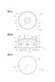
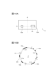
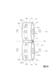
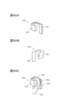
- FIG. 1 is a transparent perspective view illustrating the configuration of the acoustic signal output device of the first embodiment.
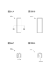
- FIG. 2A is a transparent plan view illustrating the configuration of the acoustic signal output device of the first embodiment.
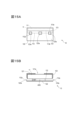
- FIG. 2B is a transparent front view illustrating the configuration of the acoustic signal output device of the first embodiment.
- FIG. 2C is a bottom view illustrating the configuration of the acoustic signal output device of the first embodiment.
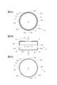
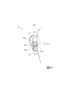
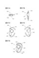
- FIG. 3A is an end view 2BA--2BA of FIG. 2B.
- FIG. 3B is an end view 2A-2A of FIG. 2A.
- FIG. 3C is an end view 2BC-2BC of FIG. 2B.
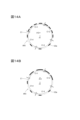
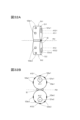
- FIG. 4 is a conceptual diagram illustrating the arrangement of sound holes.
- FIG. 4 is a conceptual diagram illustrating the arrangement of sound holes.
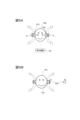
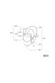
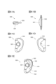
- FIG. 5A is a diagram for illustrating a usage state of the acoustic signal output device of the first embodiment
- FIG. 5B is a diagram for illustrating observation conditions for an acoustic signal emitted from the acoustic signal output device of the first embodiment.
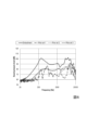
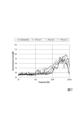
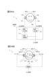
- FIG. 6 is a graph illustrating frequency characteristics of acoustic signals observed at position P1 in FIG. 5B.
- FIG. 7 is a graph illustrating frequency characteristics of acoustic signals observed at position P2 in FIG. 5B.
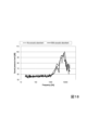
- FIG. 8 is a graph illustrating the difference between the acoustic signal observed at position P1 and the acoustic signal observed at position P2.
- 9A and 9B are graphs illustrating the relationship between the area ratio of sound holes and sound leakage.
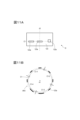
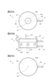
- FIG. 10A is a front view for illustrating the arrangement of sound holes.
- FIG. 10B is a conceptual diagram illustrating the arrangement of sound holes.
- FIG. 11A is a front view for illustrating the arrangement of sound holes.
- FIG. 11B is a conceptual diagram illustrating the arrangement of sound holes.
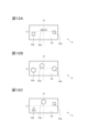
- 12A to 12C are front views for illustrating modifications of the arrangement of sound holes.
- 13A and 13B are transparent plan views for illustrating modifications of the arrangement of sound holes.
- 14A and 14B are conceptual diagrams for illustrating modifications of the arrangement of sound holes.
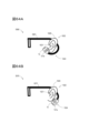
- FIG. 15A is a transparent front view for illustrating a modification of the arrangement of sound holes.
- FIG. 15B is an end view for illustrating a modification of the arrangement of the sound holes and a modification of the distance between the driver unit and the housing.
- FIG. 16A to 16C are end views for illustrating modifications of the acoustic signal output device of the first embodiment.
- FIG. 17 is a graph comparing frequency characteristics of acoustic signals observed at position P1 in FIG. 5B.
- FIG. 18 is a graph illustrating frequency characteristics of acoustic signals observed at position P2 in FIG. 5B.
- FIG. 19 is a graph illustrating the difference between the acoustic signal observed at position P1 and the acoustic signal observed at position P2.
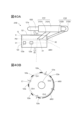
- FIG. 20 is a transparent perspective view illustrating the configuration of the acoustic signal output device of the second embodiment.
- FIG. 21A is a transparent plan view illustrating the configuration of the acoustic signal output device of the second embodiment.
- FIG. 21B is a transparent front view illustrating the configuration of the acoustic signal output device of the first embodiment.
- FIG. 21C is a bottom view illustrating the configuration of the acoustic signal output device of the first embodiment;
- FIG. 22A is an end view 21A-21A of FIG. 21B.
- FIG. 22B is a cross-sectional view taken along line 21B-21B of FIG. 21A.
- 23A and 23B are diagrams for exemplifying the state of use of the acoustic signal output device of the second embodiment.
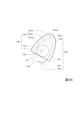
- FIG. 24 is a see-through perspective view illustrating a modification of the acoustic signal output device of the second embodiment.
- FIG. 25A is a transparent plan view illustrating a modification of the acoustic signal output device of the second embodiment.
- FIG. 25B is a transparent front view illustrating a modification of the acoustic signal output device of the second embodiment.
- FIG. 25C is a bottom view illustrating a modification of the acoustic signal output device of the second embodiment;
- FIG. 26 is an end view 25A-25A of FIG. 25B.
- FIG. 27 is a perspective view illustrating the configuration of the acoustic signal output device of the third embodiment.
- FIG. 28 is a transparent perspective view illustrating the configuration of the acoustic signal output device of the third embodiment.
- FIG. 29 is a conceptual diagram illustrating the arrangement of sound holes.
- 30A to 30C are block diagrams illustrating configurations of circuit units.
- FIG. 31 is a diagram for exemplifying the usage state of the acoustic signal output device of the third embodiment.
- 32A is a perspective view illustrating a modification of the acoustic signal output device of the third embodiment;
- FIG. 32B is a conceptual diagram illustrating a modification of the arrangement of sound holes.
- FIG. 33A is a transparent perspective view illustrating a modification of the acoustic signal output device of the third embodiment;
- FIG. 33B is a diagram illustrating a modification of the acoustic signal output device of the third embodiment;
- FIG. 34A is a diagram for illustrating the configuration of the acoustic signal output device of the fourth embodiment;
- FIG. 34B is a diagram illustrating a modification of the acoustic signal output device of the fourth embodiment
- FIG. 35A is a transparent front view for illustrating the configuration of the acoustic signal output device of the fifth embodiment
- 35B is a transparent plan view for illustrating the configuration of the acoustic signal output device of the fifth embodiment
- FIG. 35C is a transparent right side view for illustrating the configuration of the acoustic signal output device of the fifth embodiment.
- FIG. FIG. 36A is a plan view illustrating the fixing portion of the fifth embodiment
- 36B is a right side view illustrating the fixing portion of the fifth embodiment
- FIG. FIG. 36C is a front view illustrating the fixing portion of the fifth embodiment;
- FIG. 36D is a cross-sectional view 36A-36A of FIG. 36A.
- FIG. 37A is a transparent front view for illustrating a modification of the acoustic signal output device of the fifth embodiment
- 37B is a transparent plan view for illustrating a modification of the acoustic signal output device of the fifth embodiment
- FIG. 37C is a transparent right side view for illustrating a modification of the acoustic signal output device of the fifth embodiment
- FIG. FIG. 38 is a front view for illustrating a modification of the acoustic signal output device of the fifth embodiment
- 39A and 39B are front views illustrating modifications of the acoustic signal output device of the fifth embodiment.
- FIG. 37A is a transparent front view for illustrating a modification of the acoustic signal output device of the fifth embodiment
- 37B is a transparent plan view for illustrating a modification of the acoustic signal output device of the fifth embodiment
- FIG. 37C is a transparent right side view for
- FIG. 40A is a plan view illustrating a modification of the acoustic signal output device of the fifth embodiment
- FIG. 40B is a conceptual diagram illustrating a modification of the arrangement of sound holes.
- FIG. 41A is a plan view illustrating a modification of the acoustic signal output device of the fifth embodiment;
- FIG. 41B is a conceptual diagram illustrating a modification of the arrangement of sound holes.
- FIG. 42 is a transparent front view for illustrating the configuration of the acoustic signal output device of the fifth embodiment.
- FIG. 43A is a rear view for illustrating the configuration of the acoustic signal output device of the fifth embodiment;
- FIG. 43B is a cross-sectional view taken along line 43A-43A of FIG. 43A.
- FIG. 44 is a transparent front view for illustrating a modification of the acoustic signal output device of the fifth embodiment.
- FIG. 45 is a transparent front view for illustrating a modification of the acoustic signal output device of the fifth embodiment.
- FIG. 46A is a transparent front view for illustrating a modification of the acoustic signal output device of the fifth embodiment;
- 46B is a transparent bottom view for illustrating a modification of the acoustic signal output device of the fifth embodiment;
- FIG. 46C is a plan view illustrating a modification of the acoustic signal output device of the fifth embodiment;
- FIG. 47A and 47B are conceptual diagrams for illustrating modifications of the arrangement of sound holes.
- FIGS. 48A and 48B are conceptual diagrams illustrating modifications of the arrangement of sound holes.
- FIG. 49A is a front view illustrating a modification of the acoustic signal output device of the sixth embodiment
- FIG. 49B is a perspective view illustrating a modification of the acoustic signal output device of the sixth embodiment
- FIG. 50A is a perspective view illustrating a modification of the acoustic signal output device of the sixth embodiment
- FIG. 50B is a plan view illustrating a modification of the acoustic signal output device of the sixth embodiment
- FIG. 51A is a plan view illustrating a modification of the acoustic signal output device of the sixth embodiment
- FIG. 51B is a plan view illustrating a modification of the acoustic signal output device of the sixth embodiment
- FIG. 51A is a plan view illustrating a modification of the acoustic signal output device of the sixth embodiment
- FIG. 51B is a plan view illustrating a modification of the acoustic signal output device of the sixth embodiment
- FIG. 49A is a front view illustrating a modification
- FIG. 52A is a plan view illustrating a modification of the acoustic signal output device of the sixth embodiment
- FIG. 52B is a see-through perspective view for illustrating a modification of the acoustic signal output device of the sixth embodiment.
- FIG. 53A is a plan view illustrating a modification of the acoustic signal output device of the sixth embodiment;
- FIG. 53B is a right side view illustrating a modification of the acoustic signal output device of the sixth embodiment;
- FIG. 53C is a front view illustrating a modification of the acoustic signal output device of the sixth embodiment;
- FIG. 53D is a rear view for illustrating a modification of the acoustic signal output device of the sixth embodiment;
- FIG. 53A is a plan view illustrating a modification of the acoustic signal output device of the sixth embodiment
- FIG. 52B is a see-through perspective view for illustrating a modification of the acoustic signal output device of the sixth embodiment.
- FIG. 53E is a front view for illustrating the usage state of the modified example of the acoustic signal output device of the sixth embodiment.
- FIG. 54A is a perspective view illustrating a modification of the acoustic signal output device of the sixth embodiment;
- FIG. 54B is a perspective view illustrating a modification of the acoustic signal output device of the sixth embodiment;
- FIG. 54C is a perspective view illustrating a usage state of the modified example of the acoustic signal output device of the sixth embodiment.
- FIGS. 55A and 55B are front views for illustrating the state of use of the modified example of the acoustic signal output device of the sixth embodiment.
- FIG. 56A is a front view illustrating a modification of the acoustic signal output device of the sixth embodiment;
- FIG. 56A is a front view illustrating a modification of the acoustic signal output device of the sixth embodiment;
- FIG. 56A is a front view illustrating a modification of the acou
- FIG. 56B is a rear view for illustrating a modification of the acoustic signal output device of the sixth embodiment
- FIG. 56C is a front view for illustrating the usage state of the modified example of the acoustic signal output device of the sixth embodiment.
- FIG. 57A is a plan view illustrating a modification of the acoustic signal output device of the sixth embodiment
- FIG. 57B is a right side view illustrating a modification of the acoustic signal output device of the sixth embodiment
- FIG. 57C is a front view illustrating a modification of the acoustic signal output device of the sixth embodiment
- FIG. 57D is a rear view for illustrating a modification of the acoustic signal output device of the sixth embodiment
- FIG. 57E is a front view for illustrating the usage state of the modified example of the acoustic signal output device of the sixth embodiment.
- FIG. 58A is a plan view illustrating a modification of the acoustic signal output device of the sixth embodiment;
- FIG. 58B is a front view illustrating a modification of the acoustic signal output device of the sixth embodiment;
- FIG. 58C is a rear view for illustrating a modification of the acoustic signal output device of the sixth embodiment;
- FIG. 58D is a front view for illustrating the usage state of the modified example of the acoustic signal output device of the sixth embodiment.
- FIG. 59A is a plan view illustrating a modification of the acoustic signal output device of the sixth embodiment;
- FIG. 60A is a left side view illustrating a modification of the acoustic signal output device of the sixth embodiment
- FIG. 60B is a front view illustrating a modification of the acoustic signal output device of the sixth embodiment
- FIG. 60C is a front view for illustrating the usage state of the modified example of the acoustic signal output device of the sixth embodiment.
- FIG. 61A is a plan view illustrating a modification of the acoustic signal output device of the sixth embodiment
- FIG. 61B is a right side view illustrating a modification of the acoustic signal output device of the sixth embodiment
- FIG. 61C is a front view illustrating a modification of the acoustic signal output device of the sixth embodiment
- FIG. 61D is a rear view illustrating a modification of the acoustic signal output device of the sixth embodiment
- FIG. 61E is a front view for illustrating the usage state of the modified example of the acoustic signal output device of the sixth embodiment.
- 62A and 62B are conceptual diagrams illustrating modifications of the acoustic signal output device of the sixth embodiment.
- 63A and 63B are conceptual diagrams illustrating modifications of the acoustic signal output device of the sixth embodiment.
- 64A and 64B are conceptual diagrams illustrating modifications of the acoustic signal output device of the sixth embodiment.
- 65A to 65C are conceptual diagrams illustrating modifications of the acoustic signal output device of the sixth embodiment.
- the acoustic signal output device 10 of the present embodiment is a device for listening to sound (for example, open-ear earphones, headphones, etc.) worn without sealing the ear canal of the user. As illustrated in FIGS.
- the acoustic signal output device 10 of the present embodiment converts an output signal (an electrical signal representing an acoustic signal) output from a reproducing device into an acoustic signal. It has a driver unit 11 that converts it into a signal and outputs it, and a housing 12 that accommodates the driver unit 11 inside.
- the driver unit (speaker driver unit) 11 emits (sounds) an acoustic signal AC1 (first acoustic signal) based on the input output signal to one side (D1 direction side), and generates a reverse phase signal ( A device (device having a speaker function) that emits an acoustic signal AC2 (second acoustic signal), which is an approximation signal of an inverted phase signal) or an antiphase signal, to the other side (D2 direction side).
- an acoustic signal emitted from the driver unit 11 to one side is called an acoustic signal AC1 (first acoustic signal)
- an acoustic signal emitted from the driver unit 11 to the other side is called an acoustic signal AC1 (first acoustic signal).
- acoustic signal AC2 second acoustic signal
- the driver unit 11 includes a diaphragm 113 that vibrates to emit an acoustic signal AC1 from one surface 113a in the D1 direction, and vibrates to emit an acoustic signal AC2 from the other surface 113b in the D2 direction (FIG. 2B).
- the driver unit 11 of this example emits the acoustic signal AC1 from the surface 111 on one side in the D1 direction by vibrating the diaphragm 113 based on the input output signal, and outputs the opposite phase signal of the acoustic signal AC1 or An acoustic signal AC2, which is an approximation signal of the antiphase signal, is emitted from the other side 112 in the direction D2. That is, the acoustic signal AC2 is emitted secondarily with the emission of the acoustic signal AC1.
- the D2 direction (the other side) is, for example, the opposite direction of the D1 direction (one side), but the D2 direction does not have to be strictly the opposite direction of the D1 direction, as long as the D2 direction is different from the D1 direction. good.
- the relationship between one side (D1 direction) and the other side (D2 direction) depends on the type and shape of the driver unit 11 .
- the acoustic signal AC2 may be strictly the anti-phase signal of the acoustic signal AC1, or the acoustic signal AC2 may be an approximation signal of the anti-phase signal of the acoustic signal AC1. .
- the approximation signal of the anti-phase signal of the acoustic signal AC1 may be (1) a signal obtained by shifting the phase of the anti-phase signal of the acoustic signal AC1, or (2) an anti-phase signal of the acoustic signal AC1. It may be a signal obtained by changing (amplifying or attenuating) the amplitude of (3), or a signal obtained by shifting the phase of the anti-phase signal of the acoustic signal AC1 and further changing the amplitude. good.
- the phase difference between the antiphase signal of the acoustic signal AC1 and its approximation signal is preferably ⁇ 1 % or less of one period of the antiphase signal of the acoustic signal AC1.
- Examples of ⁇ 1 % are 1%, 3%, 5%, 10%, 20%, and so on. Moreover, it is desirable that the difference between the amplitude of the antiphase signal of the acoustic signal AC1 and the amplitude of its approximation signal is ⁇ 2 % or less of the amplitude of the antiphase signal of the acoustic signal AC1. Examples of ⁇ 2 % are 1%, 3%, 5%, 10%, 20%, and so on.
- Examples of the system of the driver unit 11 include a dynamic type, a balanced armature type, a hybrid type of a dynamic type and a balanced armature type, and a condenser type. Also, the shapes of the driver unit 11 and the diaphragm 113 are not limited.
- the outer shape of the driver unit 11 has a substantially cylindrical shape with both end faces and the diaphragm 113 has a substantially disk shape is shown, but this is a limitation of the present invention. isn't it.
- the outer shape of the driver unit 11 may be rectangular parallelepiped, and the diaphragm 113 may be dome-shaped.
- Examples of acoustic signals are sounds such as music, voice, sound effects, and environmental sounds.
- the housing 12 is a hollow member having a wall portion on the outside, and accommodates the driver unit 11 inside.
- the driver unit 11 is fixed to the end portion on the D1 direction side inside the housing 12 .
- the shape of the housing 12 is not limited, for example, it is desirable that the shape of the housing 12 is rotationally symmetrical (line symmetrical) or substantially rotationally symmetrical about an axis A1 extending along the D1 direction. This makes it easy to provide the sound holes 123a (details of which will be described later) so that the energy of the sound emitted from the housing 12 does not fluctuate in each direction.
- the housing 12 has a first end surface, which is a wall portion 121 arranged on one side (D1 direction side) of the driver unit 11, and a wall portion 122 arranged on the other side (D2 direction side) of the driver unit 11. and a side surface that is a wall portion 123 that surrounds the space sandwiched between the first and second end surfaces around an axis A1 passing through the first and second end surfaces (FIG. 2B , FIG. 3B).
- the housing 12 has a substantially cylindrical shape with both end faces is shown for the sake of simplicity of explanation.
- the distance between the walls 121 and 122 is 10 mm, and the walls 121 and 122 are circular with a radius of 10 mm.
- the housing 12 may have a substantially dome shape with walls at the ends, a hollow substantially cubic shape, or other three-dimensional shapes.
- the material constituting the housing 12 is not limited.
- the housing 12 may be composed of a rigid body such as synthetic resin or metal, or may be composed of an elastic body such as rubber.
- the wall portion of the housing 12 has a sound hole 121a (first sound hole) for leading an acoustic signal AC1 (first acoustic signal) emitted from the driver unit 11 to the outside, and an acoustic signal emitted from the driver unit 11.
- a sound hole 123a (second sound hole) for leading AC2 (second acoustic signal) to the outside is provided.
- the sound hole 121a and the sound hole 123a are, for example, through-holes passing through the wall of the housing 12, but this does not limit the present invention.
- the sound hole 121a and the sound hole 123a may not be through holes as long as the acoustic signal AC1 and the acoustic signal AC2 can be led out to the outside.
- the acoustic signal AC1 emitted from the sound hole 121a reaches the user's ear canal and is heard by the user.
- an acoustic signal AC2 which is a reverse phase signal of the acoustic signal AC1 or an approximation signal of the reverse phase signal, is emitted.
- Part of the acoustic signal AC2 cancels part of the acoustic signal AC1 emitted from the sound hole 121a (sound leakage component).
- an acoustic signal AC1 (first acoustic signal) is emitted from the sound hole 121a (first sound hole)
- an acoustic signal AC2 (second acoustic signal) is emitted from the sound hole 123a (second sound hole).
- the attenuation rate ⁇ 11 of the acoustic signal AC1 (first acoustic signal) at the position P2 (second point) relative to the position P1 (first point) can be set to a predetermined value ⁇ th or less
- the attenuation ⁇ 12 of the acoustic signal AC1 (first acoustic signal) at the position P2 (second point) with reference to the position P1 (first point) can be made equal to or greater than a predetermined value ⁇ th .
- the position P1 (first point) is a predetermined point at which the acoustic signal AC1 (first acoustic signal) emitted from the sound hole 121a (first sound hole) reaches.
- position P2 (second point) is a predetermined point that is farther from acoustic signal output device 10 than position P1 (first point).
- the predetermined value ⁇ th is a value ( low value). Further, the predetermined value ⁇ th is greater than the attenuation ⁇ 22 due to air propagation of an arbitrary or specific acoustic signal (sound) at the position P2 (second point) relative to the position P1 (first point). value.
- the acoustic signal output device 10 of the present embodiment is designed such that the attenuation rate ⁇ 11 is equal to or less than a predetermined value ⁇ th smaller than the attenuation rate ⁇ 21 , or the attenuation amount ⁇ 12 is It is designed to be equal to or greater than a predetermined value ⁇ th that is greater than the attenuation ⁇ 22 .
- Acoustic signal AC1 is air-propagated from position P1 to position P2, and is attenuated due to this air propagation and acoustic signal AC2.
- the attenuation factor ⁇ 11 is the magnitude AMP 2 (AC1 ) is the ratio (AMP 2 (AC1)/AMP 1 (AC1)).
- the attenuation ⁇ 12 is the difference (
- the acoustic signal AC2 is not assumed, any or particular acoustic signal AC ar air propagated from position P1 to position P2 will be attenuated due to air propagation, not due to acoustic signal AC2.
- the attenuation rate ⁇ 21 is the acoustic signal at the position P2 that is attenuated due to air propagation (attenuated without being due to the acoustic signal AC2) with respect to the magnitude AMP 1 (AC ar ) of the acoustic signal AC ar at the position P1.
- the magnitude of AC ar is the ratio of AMP 2 (AC ar ) (AMP 2 (AC ar )/AMP 1 (AC ar )).
- the attenuation ⁇ 22 is the difference (
- An example of the magnitude of the acoustic signal is the sound pressure of the acoustic signal or the energy of the acoustic signal.
- the "sound leakage component” is, for example, an area of the acoustic signal AC1 emitted from the sound hole 121a other than the user wearing the acoustic signal output device 10 (for example, the It means a component that is likely to arrive in humans (other than humans).
- the "sound leakage component” means a component of the acoustic signal AC1 that propagates in directions other than the D1 direction.
- the direct wave of the acoustic signal AC1 is mainly emitted from the sound hole 121a
- the direct wave of the second acoustic signal is mainly emitted from the second sound hole.
- Part of the direct wave of the acoustic signal AC1 emitted from the sound hole 121a is canceled by interference with at least part of the direct wave of the acoustic signal AC2 emitted from the sound hole 123a.
- the arrangement configuration of the sound holes 121a and 123a is illustrated.
- the sound hole 121a (first sound hole) of the present embodiment is an area AR1 (first area ) (FIGS. 1, 2A, 2B, and 3B). That is, the sound hole 121a is open facing the D1 direction (first direction) along the axis A1.
- the sound hole 123a (second sound hole) of the present embodiment is located between the area AR1 (first area) of the wall portion 121 of the housing 12 and the D2 direction side of the driver unit 11 (the side where the acoustic signal AC2 is emitted). provided in the area AR3 of the wall 123 that is in contact with the area AR between the area AR2 (second area) of the wall 122 arranged on the other side).
- the direction between the direction D1 (first direction) and the direction opposite to the direction D1 is the direction D12 (second direction) (FIG. 3B).
- the sound hole 123a (second sound hole) is provided on the D1 direction side (first direction side) of the housing 12, and the sound hole 123a (second sound hole) is provided on the D12 direction side (second direction side) of the housing 12.
- the housing 12 has a first end surface, which is a wall portion 121 arranged on one side (D1 direction side) of the driver unit 11, and a wall portion 122 arranged on the other side (D2 direction side) of the driver unit 11.
- the sound hole 121a (first sound hole) is provided on the first end face and the sound hole 123a (second sound hole) is provided on the side surface. is provided. Further, in this embodiment, no sound hole is provided on the wall portion 122 side of the housing 12 . If a sound hole is provided in the wall portion 122 side of the housing 12, the sound pressure level of the acoustic signal AC2 emitted from the housing 12 exceeds the level necessary to cancel out the sound leakage component of the acoustic signal AC1. This is because the excess amount is perceived as sound leakage.
- the sound hole 121a of this embodiment is arranged on or near the axis A1 along the emission direction (D1 direction) of the acoustic signal AC1.
- the axis A1 of the present embodiment passes through or near the center of a region AR1 (first region) of the wall portion 121 arranged on one side (D1 direction side) of the driver unit 11 of the housing 12 .
- the axis A1 is an axis that passes through the central region of the housing 12 and extends in the D1 direction. That is, the sound hole 121a of this embodiment is provided at the center position of the area AR1 of the wall portion 121 of the housing 12 .
- the shape of the edge of the open end of the sound hole 121a is circular (the open end is circular) is shown for the sake of simplicity of explanation.
- the radius of such sound holes 121a is, for example, 3.5 mm.
- the shape of the edge of the open end of the sound hole 121a may be oval, square, triangular, or any other shape.
- the open end of the sound hole 121a may be meshed. In other words, the open end of the sound hole 121a may be composed of a plurality of holes.
- one sound hole 121a is provided in the area AR1 (first area) of the wall portion 121 of the housing 12 .
- this does not limit the invention.
- two or more sound holes 121a may be provided in the area AR1 (first area) of the wall portion 121 of the housing 12 .
- the sound hole 123a (second sound hole) of the present embodiment is desirably arranged in consideration of, for example, the following points of view.
- Viewpoint of position The sound hole 123a is arranged so that the propagation path of the acoustic signal AC2 emitted from the sound hole 123a overlaps the propagation path of the sound leakage component of the acoustic signal AC1 to be canceled.
- Viewpoint of area The propagation region of the acoustic signal AC2 emitted from the sound hole 123a and the frequency characteristics of the housing 12 differ according to the opening area of the sound hole 123a.
- the frequency characteristics of the housing 12 affect the frequency characteristics of the acoustic signal AC2 emitted from the sound hole 123a, that is, the amplitude at each frequency.
- the sound leakage component is canceled by the acoustic signal AC2 emitted from the sound hole 123a in the region where the sound leakage component is to be canceled.
- the opening area of the sound hole 123a is determined so that From the above point of view, for example, it is desirable that the sound hole 123a (second sound hole) is configured as follows. For example, as illustrated in FIGS.
- the sound hole 123a (second sound hole) of the present embodiment is centered on the axis A1 along the emission direction of the acoustic signal AC1 (first acoustic signal). It is desirable to provide a plurality of them along the circumference (circle) C1.
- the acoustic signal AC2 is emitted radially (radially about the axis A1) to the outside from the sound holes 123a.
- the sound leakage component of the acoustic signal AC1 is also emitted radially (radially about the axis A1) to the outside from the sound hole 121a.
- the sound leakage component of the acoustic signal AC1 can be offset appropriately by the acoustic signal AC2.
- a plurality of sound holes 123a are provided on the circumference C1 for simplification of explanation.
- the sound hole 123a (second sound hole) provided along the first arc area which is one of the unit arc areas
- the total opening area is the same or substantially the same as the total opening area of the sound holes 123a (second sound holes) provided along the second arc area, which is one of the unit arc areas excluding the first arc area.
- the total opening area of the sound holes 123a (second sound holes) provided along the first circular arc region is equal to that of the unit circular arc region excluding the first circular arc region. It is the same or substantially the same as the total opening area of the sound holes 123a (second sound holes) provided along any second arc area (for example, the unit arc area C1-2).
- the circumference C1 is equally divided into four unit arc regions C1-1, . isn't it.
- " ⁇ 1 and ⁇ 2 are substantially the same” means that the difference between ⁇ 1 and ⁇ 2 is ⁇ % or less of ⁇ 1. Examples of ⁇ % are 3%, 5%, 10%, and so on.
- the sound pressure distribution of the acoustic signal AC2 emitted from the sound hole 123a provided along the first arc area and the sound pressure distribution of the acoustic signal AC2 emitted from the sound hole 123a provided along the second arc area The sound pressure distribution of AC2 is point-symmetrical or substantially point-symmetrical with respect to the axis A1.
- the total sum of the opening areas of the sound holes 123a (second sound holes) provided along each unit arc area is the same or substantially the same.
- the sound pressure distribution of the acoustic signal AC2 emitted from the sound hole 123a becomes point-symmetrical or substantially point-symmetrical with respect to the axis A1.
- the sound leakage component of the acoustic signal AC1 can be offset more appropriately by the acoustic signal AC2.
- the plurality of sound holes 123a are provided along the circumference C1 with the same shape, the same size, and the same intervals.
- a plurality of sound holes 123a having a width of 4 mm and a height of 3.5 mm are provided along the circumference C1 with the same shape, the same size, and the same intervals.
- the sound hole 123a (second sound hole) is provided in a wall portion that contacts the area AR located on the other side (D2 direction side) of the driver unit 11 (FIG. 3B).
- the direct wave of the acoustic signal AC2 emitted from the other side of the driver unit 11 is efficiently led out from the sound hole 123a.
- the sound leakage component of the acoustic signal AC1 can be offset more appropriately by the acoustic signal AC2.
- the shape of the edge of the open end of the sound hole 123a is square (the open end is square) will be exemplified, but this does not limit the present invention.
- the shape of the edge of the open end of the sound hole 123a may be a circle, an ellipse, a triangle, or any other shape.
- the open end of the sound hole 123a may be meshed.
- the open end of the sound hole 123a may be composed of a plurality of holes.
- the number of sound holes 123a is not limited, and a single sound hole 123a may be provided in the area AR3 of the wall portion 123 of the housing 12, or a plurality of sound holes 123a may be provided. .
- the ratio S2 /S1 of the sum of the opening areas of the sound holes 123a (second sound holes) to the sum S1 of the opening areas of the sound holes 121a (first sound holes) is 2 /3 ⁇ S2 / S1. It is desirable to satisfy ⁇ 4 (details will be described later). Thereby, the sound leakage component of the acoustic signal AC1 can be appropriately canceled by the acoustic signal AC2.
- the sound leakage suppression performance may also depend on the ratio between the area of the wall portion 123 in which the sound hole 123a is provided and the opening area of the sound hole 123a.
- the housing 12 has a first end surface, which is a wall portion 121 arranged on one side (D1 direction side) of the driver unit 11, and a wall portion 122 arranged on the other side (D2 direction side) of the driver unit 11. , and the space sandwiched between the first and second end faces is centered on the axis A1 along the emission direction (D1 direction) of the acoustic signal AC1 passing through the first and second end faces.
- the ratio S 2 /S 3 of the sum S 2 of the opening area of the sound holes 123a to the total area S 3 of the side surfaces is preferably 1/20 ⁇ S 2 /S 3 ⁇ 1/5 ( details will be described later).
- FIG. 5A the state of use of the acoustic signal output device 10 is illustrated.
- one acoustic signal output device 10 is attached to each of the right ear 1010 and the left ear 1020 of the user 1000 .
- Any mounting mechanism is used for mounting the acoustic signal output device 10 on the ear.
- the D1 direction side of each of the acoustic signal output devices 10 faces the user 1000 side.
- the output signal output from the playback device 100 is input to the driver unit 11 of each acoustic signal output device 10, and the driver unit 11 emits an acoustic signal AC1 to the D1 direction side and an acoustic signal AC2 to the other side. .
- Acoustic signal AC1 is emitted from sound hole 121a, emitted acoustic signal AC1 enters right ear 1010 and left ear 1020, and is heard by user 1000.
- FIG. On the other hand, from the sound hole 123a, an acoustic signal AC2, which is a reverse phase signal of the acoustic signal AC1 or an approximation signal of the reverse phase signal, is emitted. Part of the acoustic signal AC2 cancels part of the acoustic signal AC1 emitted from the sound hole 121a (sound leakage component).
- FIG. 6 illustrates the frequency characteristics of the acoustic signal observed at position P1 in FIG. 5B
- FIG. 7 illustrates the frequency characteristics of the acoustic signal observed at position P2 in FIG. 5B
- FIG. 2 illustrates the difference (difference in sound pressure level at each frequency) between the frequency characteristics of the acoustic signal observed at the position P2 and the frequency characteristics of the acoustic signal observed at the position P2.
- the horizontal axis indicates frequency (Frequency [Hz]), and the vertical axis indicates sound pressure level (SPL) [dB]).
- the solid line graph illustrates frequency characteristics when using the acoustic signal output device 10 of the present embodiment
- the dashed line graph illustrates frequency characteristics when using a conventional acoustic signal output device (open-ear earphone). do.
- a conventional acoustic signal output device open-ear earphone
- FIG. 8 when the acoustic signal output device 10 of the present embodiment is used, compared with the case of using the conventional acoustic signal output device, the acoustic signal observed at the position P1 and the acoustic signal observed at the position P2 It can be seen that the difference from the sound pressure of the acoustic signal is large. This indicates that the sound leakage at the position P2 can be suppressed in the acoustic signal output device 10 of the present embodiment as compared with the conventional acoustic signal output device.
- FIG. 9A shows the ratio S2/S1 of the total opening area of the sound hole 123a (second sound hole) to the total S1 of the opening area of the sound hole 121a (first sound hole), and the ratio S2 / S1 of the total opening area of the sound hole 121a (first sound hole).
- 2 illustrates the relationship between the difference between the frequency characteristics of the acoustic signal observed at position P2 and the frequency characteristics of the acoustic signal observed at position P2.
- the horizontal axis indicates the ratio S2 / S1
- the vertical axis indicates the sound pressure level (SPL) [dB] representing the difference.
- r12h6 shows the result when the number of sound holes 121a is 6 and the number of sound holes 123a is 4, and r12h12 shows the result when the number of sounds 21a is 12 and the number of sound holes 123a is 4.
- r45h35 illustrates the result when the number of sound holes 121a is one and the number of sound holes 123a is four. As illustrated in FIG.
- FIG. 9A shows the ratio S2 / S3 of the sum S2 of the opening area of the sound hole 123a (second sound hole) to the total side area S3 , the frequency characteristics of the acoustic signal observed at the position P1, and the position P2.
- the horizontal axis indicates the ratio S2 / S3
- the vertical axis indicates the sound pressure level (SPL) [dB] representing the difference.
- SPL sound pressure level
- the meanings of r12h6, r12h12 and r45h35 are the same as in FIG. 9A.
- the ratio S2 / S3 of the total opening area S2 of the sound hole 123a (second sound hole) to the total side area S3 is 1/20 ⁇ S2 / S3 ⁇ 1. It can be seen that in the range of /5, the difference in sound pressure between the acoustic signal observed at the position P1 and the acoustic signal observed at the position P2 is particularly large. This indicates that the sound leakage suppression effect is great in this range.
- FIGS. 10A, 10B, 11A, 11B, and 12A a plurality of sound holes 123a having different shapes and intervals may be provided in the wall portion 123 along the circumference C1.
- FIGS. 10A, 10B, 11A, 11B, and 12A a plurality of sound holes 123a having different shapes and intervals may be provided in the wall portion 123 along the circumference C1.
- 12B a plurality of sound holes 123a with different intervals may be provided in the wall portion 123 along the circumference C1.
- a second sound hole 123a may be provided in the wall portion 123 along the circumference C1.
- the sound hole 123a provided along the first arc region which is one of the unit arc regions is equal to or substantially the sum of the opening areas of the sound holes 123a provided along the second arc area, which is any of the unit arc areas excluding the first arc area. preferably identical. More preferably, the total sum of the opening areas of the sound holes 123a provided along each unit arc area for each unit arc area is the same or substantially the same. For example, as illustrated in FIGS.
- the number of sound holes 123a provided in each unit arc area C1-1, C1-2, C1-3, and C1-4 Although the sizes are different from each other, the sum of the opening areas of the sound holes 123a provided in the unit arc area C1-1, the sum of the opening areas of the sound holes 123a provided in the unit arc area C1-2, and the unit arc area It is desirable that the sum of the opening areas of the sound holes 123a provided in C1-3 and the sum of the opening areas of the sound holes 123a provided in the unit arc area C1-4 are all the same or substantially the same.
- a plurality of sound holes 123a need only be arranged along the circumference C1, and not all the sound holes 123a are strictly arranged on the circumference C1.
- not all sound holes 123a need be arranged on the circumference C1, and a plurality of sound holes 123a may be arranged along the circumference C1.
- the position of the circumference C1 is not limited to the one exemplified in the first embodiment, and may be any circumference centered on the axis A1.
- all the sound holes 123a need not be arranged along the circumference C1 as long as a sufficient sound leakage suppression effect can be obtained. That is, some of the sound holes 123a may be arranged outside the circumference C1.
- the number of sound holes 123a is not limited as long as a sufficient sound leakage suppression effect can be obtained, and one sound hole 123a may be provided.
- one sound hole is provided at the central position (hereinafter simply referred to as the "central position") of the area AR1 (the wall area arranged on one side of the driver unit) of the wall portion 121 of the housing 12.
- 121a is exemplified.
- a plurality of sound holes 121a may be provided in the region AR1 of the wall portion 121 of the housing 12, and the sound holes 121a may be displaced from the center (central position) of the region AR1 of the wall portion 121 of the housing 12. It may be biased to the eccentric position. For example, as illustrated in FIG.
- one sound hole 121a is located at an eccentric position on the area AR1 (a position on the axis A12 parallel to the axis A1 deviated from the axis A1) (hereinafter simply referred to as "eccentric position").
- eccentric position a position on the axis A12 parallel to the axis A1 deviated from the axis A1
- the position of one sound hole 121a provided in the area AR1 may be biased toward the eccentric position.
- a plurality of sound holes 121a are provided in the area AR1, and the plurality of sound holes 121a are located at eccentric positions on an axis A12 parallel to the axis A1 deviated from the axis A1. It can be biased.
- the positions of the plurality of sound holes 121a provided in the area AR1 may be eccentric. That is, a single sound hole 121a may be provided, or a plurality of sound holes 121a may be provided. may be biased toward Note that the distance between the axis A1 and the axis A2 is not limited, and may be set according to the required sound leakage suppression performance. An example of the distance between axis A1 and axis A2 is 4 mm, but this does not limit the invention.
- the resonance frequency of the housing 12 can be controlled by the arrangement configuration of the sound holes 121a provided in the area AR1 (for example, the number, size, interval, arrangement, etc. of the sound holes 121a).
- the resonance frequency of the housing 12 affects the frequency characteristics of acoustic signals emitted from the sound holes 121a and 123a. Therefore, the frequency characteristics of the acoustic signals emitted from the sound holes 121a and 123a can be controlled by the arrangement configuration of the sound holes 121a provided in the area AR1.
- the resonance frequency of the housing 12 may be controlled by setting the arrangement configuration of the sound holes 121a as shown in Examples 2-1 and 2-2 below.
- the arrangement configuration of the sound holes 121a may be set so that the human auditory sensitivity to the resonance frequency of the housing 12 is low in the high frequency band where it is difficult to suppress sound leakage.
- Sd be the human auditory sensitivity (ease of hearing) to an acoustic signal having a resonance frequency equal to or higher than a predetermined frequency fth of the housing 12 in which the sound hole 121a is located at a certain eccentric position.
- S c is the auditory sensitivity of a human to an acoustic signal having a resonance frequency equal to or higher than a predetermined frequency f th of the housing 12 in which the sound hole 121 a is provided at the center position.
- the auditory sensitivity Sd in this case is lower than the auditory sensitivity Sc . That is, the predetermined frequency f of the housing 12 where the position of the sound hole 121a (first sound hole) is biased to a certain eccentric position (a position deviated from the center of the area of the wall portion arranged on one side of the driver unit)
- the human auditory sensitivity Sd to an acoustic signal having a resonance frequency of th or more is the value obtained when it is assumed that the sound hole 121a is provided at the center position (the center of the wall region arranged on one side of the driver unit).
- the auditory sensitivity may be any indicator as long as it represents the easiness of hearing a sound. The higher the hearing sensitivity, the easier it is to hear.
- An example of auditory sensitivity is the reciprocal of the sound pressure level required for humans to perceive a reference loudness sound. For example, the reciprocal of the sound pressure level at each frequency on the equal loudness curve is the auditory sensitivity.
- the predetermined frequency fth means the lower limit of the frequency band including the frequency at which it becomes difficult to cancel the sound leakage component of the acoustic signal AC1 with the acoustic signal AC2.
- Examples of the predetermined frequency f th are 3000 Hz, 4000 Hz, 5000 Hz, 6000 Hz, and the like.
- the resonance peak of the magnitude of the acoustic signal AC1 and/or the acoustic signal AC2 emitted from the housing 12 may be altered.
- the acoustic signal AC1 emitted from the sound hole 121a and/or the acoustic signal AC2 emitted from the sound hole 123a of the housing 12 in which the position of the sound hole 121a is biased to a certain eccentric position f Let Qd be the sharpness (sharpness) of the peak above th .
- the acoustic signal AC1 first acoustic signal
- the sharpness Qd of the peak of the amplitude of the acoustic signal AC2 second acoustic signal emitted from the sound hole 123a (second sound hole) at a predetermined frequency fth or higher is determined when the sound hole 121a is provided at the center position.
- Acoustic signal AC1 (first acoustic signal) emitted from sound hole 121a (first sound hole) and/or sound emitted from sound hole 123a (second sound hole) of housing 12 when assumed to be It is duller than the peak sharpness Qc of the amplitude of the signal AC2 (second acoustic signal) above the predetermined frequency fth .
- the peak of the magnitude of the acoustic signal AC1 and/or the acoustic signal AC2 emitted from the housing 12 in which the position of the sound hole 121a is biased to a certain eccentric position at a predetermined frequency f th or higher is the sound hole 121a.
- the magnitude of the acoustic signal AC1 and/or the acoustic signal AC2 emitted from the housing 12 is flattened from the peak above the predetermined frequency fth .
- the position of the sound hole 121a may be biased to such an eccentric position.
- the distribution and opening area of the sound holes 123a may be biased accordingly.
- the position of one or more sound holes 121a provided in the area AR1 is biased to an eccentric position on the axis A12 deviated from the axis A1, as illustrated in FIGS. 14A and 14B.
- the opening area of the sound hole 121a provided in the area AR3 may also be biased toward the eccentric position on the axis A12.
- the number of sound holes 123a provided along the unit arc area C1-3 farther from the eccentric position on the axis A12 is greater than that along the unit arc area C1-1 closer to the eccentric position.
- each sound hole 123a is less than the number of sound holes 123a provided in each case.
- the opening area of each sound hole 123a provided along the unit arc region C1-3 far from the eccentric position on the axis A12 is closer to the eccentric position than that. It is smaller than the opening area of each sound hole 123a provided along the unit arc area C1-1. That is, when the circumference C1 is equally divided into a plurality of unit arc regions, the sound hole 123a (the second 2 sound holes) is the sound hole 123a provided along the second arc region (for example, C1-1) which is any of the unit arc regions closer to the eccentric position than the first arc region.
- the distribution of the acoustic signal AC1 emitted from the sound hole 121a to the outside is also biased to the eccentric position.
- the distribution of the acoustic signal AC2 emitted from the sound hole 123a to the outside can also be biased to the eccentric position.
- the sound leakage component of the acoustic signal AC1 can be sufficiently canceled by the emitted acoustic signal AC2.
- the sound hole 121a may be offset from the center (central position) of the area AR1 of the wall portion 121 of the housing 12 to an eccentric position.
- the size of the openings of the sound holes 121 a and 123 , the thickness of the walls of the housing 12 , and the volume inside the housing 12 affect the resonance frequency of the housing 12 . Therefore, by controlling at least part of these, the resonance frequency of the housing 12 can be increased or decreased. That is, the larger the size of the openings of the sound holes 121a and 123, the thinner the thickness of the walls of the housing 12, and the smaller the internal volume of the housing 12, the higher the resonance frequency of the housing 12. can do. Conversely, the smaller the size of the openings of the sound holes 121a and 123, the thicker the wall of the housing 12, and the larger the internal volume of the housing 12, the more the resonance frequency of the housing 12 increases. can be lowered.
- the acoustic signal AC2 which is an antiphase signal of the acoustic signal AC1 or an approximation signal of the antiphase signal, is emitted from the sound hole 123a, and the emitted acoustic signal Part of the acoustic signal AC1 emitted from the sound hole 121a (sound leakage component) is canceled by part of the AC2.
- the direct wave of the acoustic signal AC1 is mainly emitted from the sound hole 121a
- it is preferable that the direct wave of the acoustic signal AC2 is mainly emitted from the sound hole 123a.
- the reflected wave has a different propagation path from the direct wave
- the acoustic signal AC2 emitted from the sound hole 123a includes the reflected wave
- the acoustic signal AC2 emitted from the sound hole 123a is emitted from the sound hole 121a. This is because there is a possibility that a phase different from that of the anti-phase signal or the approximation signal of the anti-phase signal of the received acoustic signal AC1, and there is a possibility that the efficiency of canceling out the sound leakage component will decrease.
- the housing 12 has an internal structure that suppresses echoes of the acoustic signal AC2 (second acoustic signal) inside the housing 12, and the acoustic signal AC2 is mainly transmitted directly from the sound hole 123a (second sound hole).
- a configuration in which waves are emitted is desirable. An example of such a configuration is given below.
- a reverberation suppressing material eg, sponge, paper, etc.
- that suppresses reverberation may be installed in the inner regions (eg, regions AR2 and AR3) of the wall portion of the housing 12 .
- the wall portion of the housing 12 itself may be made of a reverberation suppressing material, or a sheet-like reverberation suppressing material may be fixed to the wall portion of the housing 12 .
- the inner regions (for example, the regions AR2 and AR3) of the wall of the housing 12 may be made uneven to suppress echoes.
- a sheet having an uneven surface having a reverberation suppressing effect may be fixed to the inner region of the wall of the housing 12 .
- Example 3-2 As illustrated in FIGS. 15A and 15B, the open end of the sound hole 123a (second sound hole) faces the edge portion 112a on the other side 112 (D2 direction side) of the driver unit 11, and the sound hole 123a A direct wave of the acoustic signal AC2 (second acoustic signal) emitted mainly from the other side 112 of the driver unit 11 may be emitted.
- the wall portion 122 (area AR2) arranged on the other side of the driver unit 11 is out of contact with the driver unit 11 (non-contact while the driver unit 11 is being driven), and 11 and the wall portion 122 arranged on the other side 112 of the driver unit 1 is 5 mm or less, and the acoustic signal AC2 (second acoustic signal ) may be a configuration in which a direct wave is emitted.
- the fact that the area AR2 is out of contact with the driver unit 11 while the driver unit 11 is driving means, for example, that the distance dis1 is greater than the amplitude of the other side 112 of the driver unit 11 during driving.
- the housing 12 may be provided with a sound absorbing material that absorbs high-frequency acoustic signals.
- This sound absorbing material has a characteristic that the sound absorption coefficient for the sound signal of frequency f1 is larger than the sound absorption coefficient for the sound signal of frequency f2 .
- frequency f 1 is higher than frequency f 2 (f 1 >f 2 ). That is, the sound absorbing material suppresses the high frequency components of the acoustic signal more than the low frequency components.
- the frequency f1 is less than or equal to the predetermined frequency f2th
- the frequency f2 is greater than the predetermined frequency f2th .
- Examples of the predetermined frequency f2 th are 3000 Hz, 4000 Hz, 5000 Hz and 6000 Hz.
- E in is the energy of the sound signal input to the sound absorbing material
- E out is the energy of the sound signal reflected by the sound absorbing material or the energy of the sound signal passing through the sound absorbing material.
- the sound absorbing material 13 may be provided in at least one of the sound holes 123a (second sound holes).
- the sound holes 123a may be filled with the sound absorbing material 13 .
- At least one of the inside and outside of at least one of the sound holes 123 a may be covered with the sound absorbing material 13 .
- the sound absorbing material 13 may be provided in a region on the other side 112 (D2 direction side) of the driver unit 11 inside the housing 12 .
- the sound absorbing material 13 may be fixed to the area AR2 of the wall portion 122 arranged on the other side 112 (D2 direction side) of the driver unit 11 .
- the sound absorbing material 13 may be fixed inside the wall portion 123 .
- a sound absorbing material 13 is provided in at least one of the sound holes 123a (second sound holes), and the sound absorbing material 13 is provided in a region on the other side 112 (D2 direction side) of the driver unit 11 inside the housing 12.
- the sound absorbing material 13 may be fixed to the area AR ⁇ b>2 of the wall portion 122 .
- the acoustic signal output devices 10 were attached to both ears of a dummy head 1100 imitating a human head, and acoustic signals were observed at positions P1 and P2.
- a position P1 is a position near the left ear 1120 of the dummy head 1100 (near the acoustic signal output device 10), and a position P2 is a position 15 cm outward from the position P1.
- FIG. 17 illustrates the frequency characteristics of the acoustic signal observed at position P1 in FIG. 5B
- FIG. 18 illustrates the frequency characteristics of the acoustic signal observed at position P2 in FIG. 5B
- FIG. 2 illustrates the difference between the frequency characteristics of the acoustic signal observed at position P2 and the frequency characteristics of the acoustic signal observed at position P2.
- the horizontal axis indicates frequency (Frequency [Hz]), and the vertical axis indicates sound pressure level (SPL) [dB]).
- the solid line graph illustrates the frequency characteristics when using the acoustic signal output device 10 in which the sound hole 123a is covered with a sound absorbing material (With acoustic absorbent), and the dashed line graph illustrates the frequency characteristics when using the acoustic signal output device 10 of the first embodiment.
- An example of the frequency characteristics in the case of no acoustic absorption is shown. As exemplified in FIG. 19, in the frequency band of 2000 Hz or higher, the sound signal output device 10 having the sound hole 123a covered with the sound absorbing material is generally better than the sound signal output device 10 having no sound absorbing material.
- the difference in sound pressure between the acoustic signal observed at the position P1 and the acoustic signal observed at the position P2 is greater than in the case of using. This indicates that, in a frequency band of 2000 Hz or higher, the sound leakage at the position P2 can be suppressed more generally when the sound signal output device 10 in which the sound hole 123a is covered with the sound absorbing material is used.
- the size of the driver unit 11 must be increased in order to improve the sound quality of the acoustic signal output device 10 of the first embodiment or its modification.
- the size and weight of the acoustic signal output device 10 itself also increase.
- wearing the acoustic signal output device 10 having a large size and weight near the ear canal increases the burden on the ear and the feeling of a foreign body. Therefore, the housing provided with the sound hole and the driver unit 11 may be separated and connected by a waveguide. As a result, it is possible to increase the size of the driver unit 11 without increasing the size and weight of the housing mounted near the ear canal. A detailed description will be given below.
- the acoustic signal output device 20 of the present embodiment is also a device for listening to sound that is worn without sealing the user's ear canal.
- an acoustic signal output device 20 of this embodiment includes a driver unit 11, a housing 22 having hollow portions AR21 and AR22 (first and second hollow portions), and a driver unit 11 inside.
- the driver unit 11 emits an acoustic signal AC1 (first acoustic signal) based on the input output signal to one side (D3 direction side).
- This device emits an acoustic signal AC2 (second acoustic signal), which is an approximation signal of the phase signal, to the other side (D4 direction side).
- the configuration of the driver unit 11 is the same as that of the first embodiment except that the D1 direction is replaced with the D3 direction and the D2 direction is replaced with the D4 direction.
- the housing 23 is a hollow member having a wall portion on the outside, and accommodates the driver unit 11 inside.
- the shape of the housing 23 is not limited, for example, it is desirable that the shape of the housing 23 be rotationally symmetrical (line symmetrical) or substantially rotationally symmetrical about an axis A2 extending along the D3 direction.
- the housing 23 may have a substantially dome shape with walls at the ends, a hollow substantially cubic shape, or other three-dimensional shapes.
- One end 241 of the waveguide 24 is attached to the wall portion 231 of the housing 23 arranged on the surface 111 side (D3 direction side) of the driver unit 11 .
- Waveguide 24 (first waveguide) having one end 241 connected to one side (D3 direction side) of driver unit 11 in this way emits light from surface 111 of driver unit 11 to one side (D3 direction side).
- Acoustic signal AC ⁇ b>1 thus generated is led to the outside of housing 23 .
- One end 251 of the waveguide 25 is attached to the wall portion 232 of the housing 23 arranged on the side of the surface 112 on the other side (D4 direction side) of the driver unit 11 .
- Waveguide 25 (second waveguide) having one end 251 connected to the other side (D4 direction side) of driver unit 11 in this manner emits light from surface 112 of driver unit 11 to the other side (D4 direction side). Acoustic signal AC ⁇ b>2 thus generated is led to the outside of housing 23 .
- the material constituting the housing 23 is not limited.
- the housing 23 may be composed of a rigid body such as synthetic resin or metal, or may be composed of an elastic body such as rubber.
- the waveguides 24 and 25 are, for example, tubular hollow members, and transmit acoustic signals AC1 and AC2 input from one ends 241 and 251 to the other ends 242 and 251, respectively. 252 and emitted from the other end 242,252.
- the waveguides 24 and 25 are not limited to tubular ones, and the acoustic signals collected at one ends 241 and 251 (first position) are transmitted to the other end different from the one ends 241 and 251 (first position). Any structure that leads to 242, 252 (second position) may be used.
- the length of the waveguides 24 and 25 is not limited, preferably, the length of the sound path of the waveguide 24 and the length of the sound path of the waveguide 25 are equal, or the length of the sound path of the waveguide 24 is It is desirable that the difference between the length and the length of the sound path of the waveguide 25 is an integral multiple of the wavelengths of the acoustic signals AC1 and AC2.
- the length of the sound path of the waveguide 24 (first waveguide) is L1
- the length of the sound path of the waveguide 25 (second waveguide) is L2
- n is an integer
- acoustic signal AC1 first acoustic signal
- acoustic signal AC2 second acoustic signal
- a sound path is a passage of sound.
- the length of the sound path of the waveguides 24 and 25 is the length of the waveguides 24 and 25. is.
- the waveguides 24 and 25 may be composed of a rigid body such as synthetic resin or metal, or may be composed of an elastic body such as rubber.
- the joint member 26 has an open end 261 located on one side, a wall portion 262 which is a bottom surface located on the other side of the open end 261, and a space between the open end 261 and the wall portion 263, which is arranged around the axis A1. It is a hollow member having a wall portion 263 which is a side surface surrounding the .
- the axis A1 of this embodiment passes through the open end 261 and the wall portion 263 .
- axis A1 is perpendicular or substantially perpendicular to wall 262 .
- the joining member 26 is rotationally symmetrical with respect to the axis A1.
- the wall portion 263 has a cylindrical shape
- the wall portion 263 may have another shape such as a prismatic shape.
- the other end 242 of the waveguide 24 is attached to the wall portion 263, and the acoustic signal AC1 emitted from the other end 242 of the waveguide 24 is transmitted to the inside of the joint member 26 (between the open end 261 and the wall portion 263). space between). Acoustic signal AC1 introduced into joint member 26 is emitted from open end 261 .
- the material constituting the joint member 26 is not limited.
- the joining member 26 may be composed of a rigid body such as synthetic resin or metal, or may be composed of an elastic body such as rubber.
- the joining member 27 has an open end 271 located on one side, a wall portion 272 which is a bottom surface located on the other side of the open end 271, and a space between the open end 271 and the wall portion 273, which is defined by an axis line. It is a hollow member having a wall portion 273 which is a side surface surrounding A1 at the center.
- the axis A1 of this embodiment passes through the open end 271 and the wall portion 273 .
- axis A1 is perpendicular or substantially perpendicular to wall 272 .
- the joint member 27 is rotationally symmetrical with respect to the axis A1.
- the wall portion 273 may have another shape such as a prismatic shape.
- the other end 252 of the waveguide 25 is attached to the wall portion 273, and the acoustic signal AC2 emitted from the other end 252 of the waveguide 25 is transmitted to the inside of the joint member 27 (between the open end 271 and the wall portion 273). space between). Acoustic signal AC ⁇ b>2 introduced into joint member 27 is emitted from open end 271 .
- the joining member 27 may be composed of a rigid body such as synthetic resin or metal, or may be composed of an elastic body such as rubber.
- the housing 22 of the present embodiment includes a wall portion 221 located on one side (D1 direction side) and a wall portion 221 located on the other side (D2 direction side). a wall portion 222 positioned on the side), a wall portion 223 surrounding a space between the wall portions 221 and 222, and a space surrounded by the wall portions 221, 222, and 223 as a hollow portion It has a wall portion 224 separating the AR21 (first hollow portion) and the hollow portion AR22 (second hollow portion).
- the hollow portions AR21 and AR22 are arranged on the same axis A1 extending in the D1 direction.
- the central regions of the hollow portions AR21 and AR22 are arranged on the same axis A1 are placed.
- the internal space of hollow portion AR21 is desirably separated from the internal space of hollow portion AR22 by wall portion 224 .
- a joint member 26 to which the other end 242 of the waveguide 24 is attached is fixed or integrated with the inner wall portion of the hollow portion AR21, and the open end 261 side of the joint member 26 is directed toward the wall portion 221 side.
- the wall portion 262 side of the joint member 26 is fixed to or integrated with the wall portion 224 inside the hollow portion AR21, and the open end 261 side faces the wall portion 221 side.
- the center of the wall portion 262 and the open end 261 of the joining member 26 is arranged on the axis A1.
- the other end 242 of the waveguide 24 is connected to the hollow portion AR21 through the joint member 26, and the acoustic signal AC1 sent to the joint member 26 is transmitted from the open end 261 to the wall portion 221 side (D1 direction side). released towards. That is, for example, the joint member 26 is arranged on the axis A1, the open end 261 of the joint member 26 is opened in the direction D1 (first direction) along the axis A1, and the other end of the waveguide 24 Acoustic signal AC1 introduced from 242 is emitted toward direction D1 inside hollow part AR21.
- a through hole 222a is provided in the wall portion 222 of the hollow portion AR22.
- the through hole 222a is preferably arranged on the axis A1, and more preferably, the center of the through hole 222a is arranged on the axis A1.
- the shape of the through-hole 222a is not limited, but it is preferable that the open portion of the through-hole 222a is rotationally symmetrical with respect to the axis A1, and more preferably, the edge of the open portion of the through-hole 222a is circular.
- a joint member 27 to which the other end 252 of the waveguide 25 is attached is fixed or integrated to the outside of the wall portion 222 of the housing 22, and the open end 271 side of the joint member 27 is directed to the through hole 222a.
- the wall portion 272 of the joining member 27, the open end 271, and the center of the through hole 222a are arranged on the axis A1.
- the other end 252 of the waveguide 25 is connected to the hollow portion AR22 via the joint member 27, and the acoustic signal AC2 sent to the joint member 27 is emitted from the open end 271 toward the inner space of the hollow portion AR22. be done.
- the acoustic signal AC2 is emitted from the open end 271 toward the wall portion 224 side (D1 direction side). That is, for example, the joint member 27 is arranged on the axis A1, and the open end 271 of the joint member 27 is opened in a direction D1 (first direction) along the axis A1, and the other end of the waveguide 25 Acoustic signal AC2 introduced from 252 is emitted toward direction D1 inside hollow part AR22.
- the shape of the housing 22 is not limited, for example, it is desirable that the shape of the housing 22 is rotationally symmetrical or substantially rotationally symmetrical about the axis A1.
- the outer shape of the housing 22 is a substantially cylindrical shape having wall portions 221 and 222 as both end surfaces and a wall portion 223 as a side surface.
- the wall portions 221, 222, and 224 are perpendicular or substantially perpendicular to the axis A1, and the wall portion 223 is parallel or substantially parallel to the axis A1.
- these are only examples and do not limit the present invention.
- the external shape of the housing 22 may be a substantially dome shape with walls at the ends, a hollow substantially cubic shape, or other three-dimensional shapes.
- the material of which the housing 22 is made is not limited.
- the housing 22 may be composed of a rigid body such as synthetic resin or metal, or may be composed of an elastic body such as rubber.
- ⁇ Sound holes 221a, 223a> The acoustic signal AC1 (first acoustic signal) introduced into the hollow portion AR21 by the waveguide 24 (first waveguide) is led to the wall portion 221 of the hollow portion AR21 (first hollow portion) to the outside. A sound hole 221a (first sound hole) is provided. Further, the wall portion 223 of the hollow portion AR22 (second hollow portion) receives the acoustic signal AC2 (second acoustic signal) introduced into the hollow portion AR22 by the waveguide 25 (second waveguide). 221a (second sound hole) is provided.
- the sound hole 221a and the sound hole 223a are, for example, through-holes passing through the wall of the housing 12, but this does not limit the present invention. do not have.
- the sound hole 221a and the sound hole 223a may not be through holes as long as the acoustic signal AC1 and the acoustic signal AC2 can be led out to the outside.
- the acoustic signal AC1 emitted from the sound hole 221a reaches the user's ear canal and is heard by the user.
- the sound hole 223a emits an acoustic signal AC2, which is an anti-phase signal of the acoustic signal AC1 or an approximation signal of the anti-phase signal.
- a portion of the acoustic signal AC2 cancels a portion (sound leakage component) of the acoustic signal AC1 emitted from the sound hole 221a. Thereby, sound leakage can be suppressed.
- the arrangement configuration of the sound holes 221a and 223a is illustrated.
- the sound hole 221a (first sound hole) of the present embodiment is provided in the wall portion 221 of the hollow portion AR21 arranged on one side of the joint member 26 (the D1 direction side from which the acoustic signal AC1 is emitted).
- the sound hole 223a (second sound hole) of the present embodiment is provided in the wall portion 223 in contact with the hollow portion AR22. That is, with the center of the hollow portion AR22 as a reference, the direction between the D1 direction (first direction) and the direction opposite to the D1 direction is defined as the D12 direction (second direction) (FIG. 22A).
- the sound hole 223a (second sound hole) is provided on the D1 direction side (first direction side) of the housing 22, and the sound hole 223a (second sound hole) is provided on the D12 direction side (second direction side) of the housing 22. It is That is, the sound hole 221a opens in the D1 direction (first direction) along the axis A1, and the sound hole 223a opens in the D12 direction (second direction).
- the housing 22 has a first end surface that is a wall portion 221 arranged on one side (D1 direction side) of the joint member 26 and a wall arranged on the other side (D2 direction side) of the joint member 26.
- the space sandwiched between the second end surface, which is the portion 222, and the first and second end surfaces is defined by an axis A1 along the emission direction (D1 direction) of the acoustic signal AC1 passing through the first and second end surfaces.
- the sound hole 221a first sound hole
- the sound hole 223a second sound hole
- no sound hole is provided on the wall portion 222 side of the housing 22 .
- the sound pressure level of the acoustic signal AC2 emitted from the housing 22 exceeds the level necessary to cancel out the sound leakage component of the acoustic signal AC1. This is because the excess amount is perceived as sound leakage.
- the sound hole 221a of the present embodiment is arranged on or near the axis A1 along the emission direction (D1 direction) of the acoustic signal AC1.
- the axis A1 of the present embodiment passes through the center of the region of the wall portion 221 arranged on one side (D1 direction side) of the joint member 26 or the vicinity of the center.
- the axis A1 is an axis that passes through the central region of the housing 22 and extends in the D1 direction. That is, the sound hole 221a of this embodiment is provided at the central position of the area of the wall portion 221 of the housing 22 .
- the shape of the edge of the open end of the sound hole 221a is circular (the open end is circular) is shown for the sake of simplicity of explanation.
- the shape of the edge of the open end of the sound hole 221a may be oval, square, triangular, or any other shape.
- the open end of the sound hole 221a may be meshed.
- the open end of the sound hole 221a may be composed of a plurality of holes.
- the wall portion 221 of the housing 22 may be provided with two or more sound holes 221a.
- the sound hole 223a (second sound hole) of the present embodiment has an axis A1 along the emission direction of the acoustic signal AC1 (first acoustic signal). are provided along a circumference C1 centered on .
- an example in which a plurality of sound holes 223a are provided on the circumference C1 is shown for simplification of explanation. However, it is sufficient that the plurality of sound holes 223a are provided along the circumference C1, and not all the sound holes 223a are strictly arranged on the circumference C1.
- the sound hole 223a is provided along the first arc area which is one of the unit arc areas.
- the sum of the opening areas of the (second sound holes) is the opening area of the sound holes 223a (second sound holes) provided along the second arc area, which is any of the unit arc areas excluding the first arc area. is the same or nearly the same as the sum of (FIG. 22B).
- the plurality of sound holes 223a have the same shape, the same size, and the same spacing along the circumference C1.
- this is not a limitation of the invention.
- the shape of the edge of the open end of the sound hole 223a is a square is exemplified, but this does not limit the present invention.
- the shape of the edge of the open end of the sound hole 223a may be a circle, an ellipse, a triangle, or any other shape.
- the open end of the sound hole 223a may be meshed.
- the open end of the sound hole 223a may be composed of a plurality of holes.
- the number of sound holes 223a is not limited, and the wall portion 223 of the housing 22 may be provided with a single sound hole 223a or a plurality of sound holes 223a.
- the ratio S2/ S1 of the sum of the opening areas of the sound holes 223a (second sound holes) to the sum S1 of the opening areas of the sound holes 221a (first sound holes) is 2 / It is desirable to satisfy 3 ⁇ S 2 /S 1 ⁇ 4.
- the outer shape of the housing 22 consists of a first end face, which is a wall portion 221 arranged on one side (D1 direction side) of the joint member 26, and a wall arranged on the other side (D2 direction side) of the joint member 26.
- the space sandwiched between the second end surface, which is the portion 222, and the first and second end surfaces is defined by an axis A1 along the emission direction (D1 direction) of the acoustic signal AC1 passing through the first and second end surfaces. 21B and 22A), the ratio S2 / S3 of the sum of the opening areas S2 of the sound holes 123a to the total area S3 of the side surfaces is 1/20. It is desirable that ⁇ S 2 /S 3 ⁇ 1/5.
- FIGS. 23A and 23B the state of use of the acoustic signal output device 20 is illustrated.
- one acoustic signal output device 20 is attached to each of the user's 1000 right ear 1010 and left ear (not shown). Any mounting mechanism is used for mounting the acoustic signal output device 20 on the ear.
- the housing 22 of the acoustic signal output device 20 is arranged on the side of the ear canal 1011 of the right ear 1010 and the left ear, and the D1 direction side is directed to the ear canal 1011 side of the user 1000 .
- the playback device 210 including the housing 23 is arranged behind the auricle of the right ear 1010 and the left ear, respectively, and the housings 23 and 22 are connected by the waveguides 24 and 25 as described above. .
- An acoustic signal AC1 introduced from the driver unit 11 in the housing 23 into the hollow part AR21 of the housing 22 is emitted from the sound hole 221a, and the emitted acoustic signal AC1 is heard by the user 1000.
- the acoustic signal AC2 introduced from the driver unit 11 inside the housing 23 into the hollow portion AR22 of the housing 22 is emitted from the sound hole 123a.
- a part of the acoustic signal AC2 is an anti-phase signal or an approximation signal of the anti-phase signal of the acoustic signal AC1, and cancels a part (sound leakage component) of the acoustic signal AC1 emitted from the sound hole 221a.
- the playback device 210 including the housing 23 is placed on the head on the front side of the right ear 1010 and the auricle of the left ear, and the housing 23 and the housing 22 are guided as described above. They may be connected by tubes 24,25. Others are the same as the example of FIG. 23A.
- Modification 2 of Second Embodiment In the second embodiment, the configuration in which one sound hole 221a is arranged at the central position of the wall portion 221 of the housing 22 is exemplified.
- a plurality of sound holes 221a may be provided in the region of the wall portion 221 of the housing 22, or the sound holes 221a may be formed in the wall portion 221 of the housing 22. It may be biased to an eccentric position shifted from the center of the region.
- the housing 22 may be provided with sound holes 221a having the same arrangement configuration as the arrangement configuration of the sound holes 121a in Modification 2 of the first embodiment (FIGS. 13A and 13B).
- the distribution and opening area of the sound holes 223a may be biased accordingly. That is, when the circumference C1 is equally divided into a plurality of unit arc areas, the opening area of the sound hole 223a (second sound hole) provided along the first arc area which is one of the unit arc areas may be smaller than the sum of the opening areas of the sound holes 123a provided along the second arc area, which is any unit arc area closer to the eccentric position than the first arc area.
- the housing 22 may be provided with sound holes 223a having the same arrangement configuration as the arrangement configuration of the sound holes 123a in Modification 2 of the first embodiment (FIGS. 14A and 14B).
- the resonance frequency of the housing 22 is controlled by controlling the size of the openings of the sound holes 221a and 223, the thickness of the walls of the housing 22, and at least part of the volume inside the housing 22.
- the acoustic signal output device 20 is provided with a sound absorbing material having a higher sound absorption coefficient for the frequency f 1 sound signal than the sound absorption coefficient for the frequency f 2 (f 1 >f 2 ) sound signal described in the modification 4 of the first embodiment.
- the sound absorbing material may be provided on the other side 112 (D4 direction side) of the driver unit 11 inside the housing 23, or may be provided inside the waveguide 25 (second waveguide). However, it may be provided at the end portion (open end portion) of the waveguide 25, or may be provided in at least one of the sound holes 223a (second sound hole), or may be provided in the hollow portion AR22 (second sound hole). 2 hollow portion).
- the housing 12 is replaced with the hollow part AR22, the sound hole 123a is replaced with the sound hole 223a, and the other side of the driver unit 11 is replaced.
- a configuration in which the region 112 is replaced with the inner region of the hollow portion AR22 and the region AR2 of the wall portion 122 is replaced with the region of the wall portion 222 may be used.
- the emission directions of the acoustic signals AC1 and AC2 in the hollow portions AR21 and AR22 can be controlled.
- the acoustic signal AC1 introduced from the other end 242 of the waveguide 24 is emitted in the direction D1 along the axis A1 inside the hollow portion AR21
- the acoustic signal AC2 introduced from the other end 252 of the waveguide 25 is emitted.
- the sound pressure distributions of the acoustic signal AC1 emitted from the sound hole 221a and the acoustic signal AC2 emitted from the sound hole 223a can be rotationally symmetrical or substantially rotationally symmetrical with respect to the axis A1. This makes it possible to appropriately suppress sound leakage.
- this is not a limitation of the invention.
- the acoustic signal output device 20 does not have the joining member 26, and the other end 242 of the waveguide 24 is directly hollow.
- the acoustic signal AC1 connected to the wall portion 223 of the portion AR21 and sent to the other end 242 of the waveguide 24 may be emitted toward the inside of the hollow portion AR21.
- the acoustic signal output device 20 does not have the joint member 27, and the other end 252 side of the waveguide 25 is directly connected to the wall portion 223 of the hollow portion AR22 to transmit to the other end 252 of the waveguide 25.
- the received acoustic signal AC2 may be emitted toward the interior of the hollow portion AR22.
- the example in which the internal space of the hollow portion AR21 of the housing 22 is separated from the internal space of the hollow portion AR22 by the wall portion 224 is shown. (FIGS. 20, 21B, 22A).
- the internal space of the hollow portion AR21 of the housing 22 does not have to be separated from the internal space of the hollow portion AR22.
- the open end 261 of the joint member 26 faces the wall portion 221 side (D1 direction side) of the housing 22 (for example, the sound hole 221a side), and the open end 271 of the joint member 27 faces the housing 22. It is preferably oriented toward the wall portion 222 side (D2 direction side). Even with such a configuration, the acoustic signal AC1 is emitted from the sound hole 221a, and the acoustic signal AC2 is emitted from the sound hole 223a.
- a plurality of acoustic signal output devices 10 described in the first embodiment or its modification may be provided and controlled independently.
- the sound pressure level of the acoustic signal AC1 emitted from a certain acoustic signal output device 10 and the sound pressure level of the acoustic signal AC2 emitted from the other acoustic signal output device 10 can be independently controlled.
- a certain acoustic signal output device 10 and another acoustic signal output device 10 can be driven in antiphase or substantially antiphase, and the level (power) at each frequency can be controlled independently.
- the sound leakage components of the acoustic signal AC1 of the individual acoustic signal output devices 10 are partially offset by the acoustic signal AC2, and from the different acoustic signal output devices 10 A part of the output acoustic signal AC1 and a part of the acoustic signal AC2 can be offset. As a result, it becomes possible to cancel out sound leakage components more appropriately.
- this embodiment for simplification of explanation, an example in which two acoustic signal output devices 10 are provided for one ear and controlled independently is shown. However, this does not limit the invention, and three or more acoustic signal output devices 10 may be provided for one ear and controlled independently.
- the two acoustic signal output devices 10 are referred to as an acoustic signal output device 10-1 and an acoustic signal output device 10-2. are identical.
- the acoustic signal output device 30 of this embodiment is a device for listening to sound that is worn without sealing the user's external auditory canal. As illustrated in FIGS. 27 and 28, the acoustic signal output device 30 of this embodiment has acoustic signal output devices 10-1 and 2, a circuit section 31, and a connection section 32. FIG.
- the configuration of the acoustic signal output device 10-1 is the same as the acoustic signal output device 10 exemplified in the first embodiment and its modifications. That is, the acoustic signal output device 10-1 has a driver unit 11-1 (first driver unit) and a housing 12-1 (first housing section) housing the driver unit 11-1 therein. .
- the driver unit 11-1 emits an acoustic signal AC1-1 (first acoustic signal) in the D1-1 direction (one side) based on the input output signal I (electrical signal representing the acoustic signal), and D2.
- An acoustic signal AC2-1 (second acoustic signal), which is an anti-phase signal of the acoustic signal AC1-1 (first acoustic signal) or an approximation signal of the anti-phase signal, is emitted to the -1 direction side (the other side).
- the wall portion 121-1 of the housing 12-1 has one or more sound holes 121a-1 (first 1 tone hole) are provided.
- a wall portion 123-1 of the housing 12-1 has one or more sound holes 123a-1 (second 2 tone holes) are provided.
- the details of the configuration of the acoustic signal output device 10-1 are the same as those of the acoustic signal output device 10 described in the first embodiment.
- the sound hole 123a-1 (second sound hole) has a circumference C1- 1 (first circumference) are provided (FIG. 29).
- the circumference C1-1 first circumference
- the The total opening area of the sound hole 123a-1 (second sound hole) is the sound hole 123a-1 provided along the second arc area which is any of the first unit arc areas excluding the first arc area. It is the same or substantially the same as the total opening area of the (second sound holes).
- the configuration of the acoustic signal output device 10-2 is also the same as the acoustic signal output device 10 exemplified in the first embodiment and its modification. That is, the acoustic signal output device 10-2 has a driver unit 11-2 (second driver unit) and a housing 12-2 (second housing section) housing the driver unit 11-2 therein. .
- the driver unit 11-2 emits an acoustic signal AC1-2 (fourth acoustic signal) in the direction of D1-2 (one side) based on the input output signal II (electrical signal representing the acoustic signal).
- An acoustic signal AC2-2 (third acoustic signal), which is an anti-phase signal of the acoustic signal AC1-2 or an approximation signal of the anti-phase signal, is emitted to the -2 direction side (the other side).
- the phase of the acoustic signal AC1-2 (fourth acoustic signal) is the same as or approximates the phase of the acoustic signal AC2-1 (second acoustic signal).
- the phase of the acoustic signal AC2-2 (third acoustic signal) is the same as or approximates the phase of the acoustic signal AC1-1 (first acoustic signal).
- the driver unit 11-2 may have the same design as the driver unit 11-1, or may have a different design from the driver unit 11-1.
- the driver unit 11-2 may be smaller than the driver unit 11-1, or the performance of the driver unit 11-2 may be inferior to that of the driver unit 11-1.
- a wall portion 123-2 of the housing 12-2 has one or more sound holes 123a-2 (third 3 tone holes) are provided.
- a wall portion 121-2 of the housing 12-2 is provided with one or more sound holes 121a-2 (fourth acoustic signal) for leading out the acoustic signal AC1-2 (fourth acoustic signal) emitted from the driver unit 11-2. 4 tone holes) are provided.
- the sound hole 123a-2 (third sound hole) has a circumference C1- 2 (fourth circumference) (FIG. 29).
- the circumference C1-2 fourth circumference
- the The total opening area of the sound hole 123a-2 is the sound hole 123a-2 provided along the fourth unit arc area, which is one of the fourth unit arc areas excluding the third arc area. It is the same or substantially the same as the total opening area of the (third sound holes).
- the connecting portion 32 fixes the housing 12-1 of the acoustic signal output device 10-1 and the housing 12-2 of the acoustic signal output device 10-2 to each other. are doing.
- the outside of the wall portion 123-1 of the housing 12-1 of the acoustic signal output device 10-1 and the outside of the wall portion 123-2 of the housing 12-2 of the acoustic signal output device 10-2. is joined with.
- the sound hole 121a-1 (first sound hole) opens in a direction D1-1 (first direction) along the axis A1-1.
- the direction D1-1 is a direction along the axis A1-1.
- the sound hole 123a-1 (second sound hole) faces in a direction D12-1 (second direction) between direction D1-1 (first direction) and the opposite direction of direction D1-1 (first direction). is open.
- the sound hole 121a-2 (fourth sound hole) opens in a direction D1-2 (fourth direction) that is the same as or similar to the direction D1-1 (first direction).
- the direction D1-2 is a direction along the axis A1-2.
- the sound hole 123a-2 (third sound hole) faces D12-2 (third direction) between the direction D1-2 (fourth direction) and the opposite direction of direction D1-2 (fourth direction). It's open.
- this arrangement configuration is an example and does not limit the present invention.
- the sound hole 121a-1 (first sound hole) and the sound hole 121a-2 (fourth sound hole) are preferably arranged in the direction D1-1 (first direction ) extending parallel to or substantially parallel to the straight line (axis A1-1).
- the sound hole 123a-1 (second sound hole) and the sound hole 123a-2 (third sound hole) are preferably plane-symmetrical or approximately plane-symmetrical with respect to the reference plane P31.
- housing 12-1 (first housing section) and housing 12-2 (second housing section) are plane-symmetrical or substantially plane-symmetrical with respect to reference plane P31.
- the circuit unit 31 uses an input signal, which is an electric signal representing an acoustic signal, as an input, and outputs an output signal I, which is an electric signal for driving the driver unit 11-1, and an electric signal for driving the driver unit 11-2. is a circuit for outputting an output signal II.
- the output signal I and the output signal II are electric signals representing acoustic signals, and the output signal II is an antiphase signal of the output signal I or an approximation signal of the antiphase signal.
- the configuration of the circuit section 31 is exemplified below.
- the circuit section 31 illustrated in FIG. 30A has a phase inverter section 311 which is a phase inverter circuit.
- An input signal input to the circuit section 31 is output as it is as an output signal I and supplied to the driver unit 11-1. Further, the input signal input to the circuit section 31 is also input to the phase inverter section 311 .
- the phase inverter 311 outputs a reverse phase signal of the input signal or an approximation signal of the reverse phase signal as an output signal II.
- the output signal II is supplied to the driver unit 11-2.
- the circuit section 31 illustrated in FIG. 30B has a level correction section 312 , a phase control section 313 and a delay correction section 314 .
- An input signal input to the circuit section 31 is input to the level correction section 312 and the delay correction section 314 .
- the level correction section 312 adjusts the level of each frequency band of the input signal and outputs the resulting band level adjusted signal. That is, if the driver units 11-1 and 11-2 are different in design (aperture, structure, etc.), the frequency characteristics of the acoustic signals output from the driver units 11-1 and 2 are also different. The difference in the frequency characteristics of the acoustic signals output from the driver units 11-1 and 11-2 is related to the canceling effect of sound leakage.
- the acoustic signals output from the driver units 11-1 and 11-2 are adjusted to enhance the effect of sound leakage cancellation. It is desirable that the frequency characteristics are the same. Therefore, it is desirable to adjust the output signals so that the frequency characteristics of the acoustic signals output from the driver units 11-1 and 2 are the same.
- the driver unit 11-1 is arranged in such a way as to enhance the effect of canceling out the sound leakage according to their asymmetry. , 2 to balance the frequency characteristics of the acoustic signals.
- the level correction section 312 realizes these by adjusting the level of each band of the input signal.
- the band level-adjusted signal output from level correction section 312 is input to phase control section 313 .
- Phase control section 313 generates an anti-phase signal of the band level-adjusted signal or an approximation signal of the anti-phase signal, and outputs this as output signal II.
- the phase controller 313 is, for example, a phase inverter circuit or an all-pass filter. When the phase control section 313 is an all-pass filter, the phase characteristic of the level correction section 312 can be taken into consideration to generate an anti-phase signal of the band level-adjusted signal or an approximation signal of the anti-phase signal.
- the output signal II is supplied to the driver unit 11-2. Further, the delay correction unit 314 outputs an output signal I obtained by adjusting the delay amount of the input signal. That is, when a delay occurs in the processing (filter processing) of the level correction section 312 and the phase control section 313, the delay correction section 314 adjusts the amount of delay. As a result, the phases of the acoustic signals output from the driver units 11-1 and 11-2 can be adjusted, and the effect of suppressing sound leakage can be improved.
- the output signal I is supplied to the driver unit 11-1. As described above, in configuration example 2 of the circuit unit 31, the output signal I and the output signal II based on the input signal can be independently controlled.
- the importance of the acoustic signal AC2 for suppressing sound leakage components is low in such a low frequency band. Furthermore, the human hearing sensitivity to acoustic signals with frequencies between 2000 Hz and 6000 Hz is relatively high. In other words, the importance of the acoustic signal AC2 that suppresses the sound leakage component of the acoustic signal AC1 in such a frequency band is high.
- the frequency band of the acoustic signal emitted from the acoustic signal output device 10-1 when the user listens to the acoustic signal AC1 emitted from the sound hole 121a-1 of the acoustic signal output device 10-1, the frequency band of the acoustic signal emitted from the acoustic signal output device 10-2 is , the frequency band of the acoustic signal emitted from the acoustic signal output device 10-1 may be restricted.
- the frequency bandwidth BW-2 of the acoustic signal AC2-2 and the acoustic signal AC1-2 (third acoustic signal and fourth acoustic signal) emitted from the driver unit 11-2 (second driver unit) is
- the frequency bandwidth BW-1 of the acoustic signals AC1-1 and AC2-1 (first acoustic signal and second acoustic signal) emitted from 11-1 (first driver unit) may be narrower than BW-1.
- Example 31-1 For example, the magnitude (level) on the high frequency side of the acoustic signal AC2-2 and the acoustic signal AC1-2 may be suppressed more than the magnitude on the high frequency side of the acoustic signal AC1-1 and the acoustic signal AC2-1. . That is, the component of frequency f 31 (first frequency) or higher of acoustic signals AC2-2 and AC1-2 (third acoustic signal and fourth acoustic signal) emitted from driver unit 11-2 (second driver unit) The magnitude is greater than the magnitude of components of frequency f31 or higher of acoustic signals AC1-1 and AC2-1 (first acoustic signal and second acoustic signal) emitted from driver unit 11-1 (first driver unit).
- the driver unit 11-2 may output the acoustic signal AC2-2 and the acoustic signal AC1-2 in which the frequency band above the frequency f31 is suppressed.
- specific examples of the frequency f31 are 3000 Hz, 4000 Hz, 5000 Hz, 6000 Hz, and the like.
- Example 31-2 For example, the magnitudes of the audio signals AC2-2 and AC1-2 on the low frequency side may be suppressed more than the magnitudes of the audio signals AC1-1 and AC2-1 on the low frequency side. That is, the components below frequency f 32 (second frequency) of acoustic signals AC2-2 and AC1-2 (third acoustic signal and fourth acoustic signal) emitted from driver unit 11-2 (second driver unit) The magnitude is greater than the magnitude of the components below frequency f32 of the acoustic signals AC1-1 and AC2-1 (first and second acoustic signals) emitted from the driver unit 11-1 (first driver unit). It can be small.
- the driver unit 11-2 may output the acoustic signal AC2-2 and the acoustic signal AC1-2 in which the frequency band below the frequency f32 is suppressed.
- specific examples of the frequency f32 are 1000 Hz, 2000 Hz, 3000 Hz, and the like.
- Example 31-3 For example, the magnitudes of the audio signal AC2-2 and the audio signal AC1-2 on the high frequency side are suppressed more than the magnitudes of the audio signal AC2-1 and the audio signal AC1-1 on the high frequency side, and the audio signal AC2- 2 and the amplitude of the acoustic signal AC1-2 on the low frequency side may be suppressed more than the amplitude of the acoustic signal AC2-1 and the acoustic signal AC1-1 on the low frequency side.
- the driver unit 11-2 outputs the acoustic signal AC2-2 and the acoustic signal AC1-2 in which the frequency band below the frequency f32 and the frequency band above the frequency f31 are suppressed (for example, frequency f32 and frequency f31 ).
- the circuit section 31 of this example has a level correction section 312 , a phase control section 313 , a delay correction section 314 and a bandpass filter section 315 .
- An input signal input to the circuit section 31 is input to the bandpass filter section 315 and the delay correction section 314 .
- Bandpass filter section 315 obtains and outputs a band-limited signal obtained by limiting (narrowing) the band of the input signal.
- a signal obtained by suppressing the high frequency side of the input signal for example, the frequency band above frequency f31
- the band-limited signal for example, the frequency band above frequency f31
- a signal obtained by suppressing the low-frequency side of the input signal (for example, the frequency band below frequency f32 ) is output as the band-limited signal.
- a signal obtained by suppressing the high frequency side (for example, the frequency band of frequency f31 or higher) and the low frequency side (for example, the frequency band of frequency f32 or lower) of the input signal is used as the band-limited signal. output.
- the band-limited signal is input to level correction section 312 .
- Level correction section 312 adjusts the level of each band of the band-limited signal and outputs the band-level-adjusted signal obtained thereby.
- the band level-adjusted signal output from level correction section 312 is input to phase control section 313 .
- Phase control section 313 generates an anti-phase signal of the band level-adjusted signal or an approximation signal of the anti-phase signal, and outputs this as output signal II.
- the output signal II is supplied to the driver unit 11-2.
- the delay correction unit 314 outputs an output signal I obtained by adjusting the delay amount of the input signal.
- FIG. 31 the state of use of the acoustic signal output device 30 is illustrated.
- One acoustic signal output device 30 is attached to each of the right ear 1010 and the left ear (not shown) of the user 1000 in FIG.
- the D1 direction side of the acoustic signal output device 10-1 of the acoustic signal output device 30 is directed to the ear canal 1011 side of the user 1000.
- FIG. Also, the acoustic signal output device 10-2 is arranged at a position shifted from the external auditory canal 1011.
- the sound hole 121a-1 (first sound hole) is arranged in the direction of the ear canal 1022, and the sound hole 123a-1 (second sound hole) and the sound hole 123a are arranged toward the ear canal 1022.
- -2 third sound hole and sound hole 121a-2 (fourth sound hole) are arranged in a direction other than the external auditory canal 1022.
- Any mounting mechanism is used to mount the acoustic signal output device 30 on the ear.
- the user 1000 listens to the acoustic signal AC1-1 (first acoustic signal) emitted from the sound hole 121a-1 (first sound hole) of the acoustic signal output device 10-1.
- part of the acoustic signal AC2-1 (second acoustic signal) emitted from the sound hole 123a-1 (second sound hole) is the acoustic signal AC1 emitted from the sound hole 121a-1 (first sound hole).
- Cancel part of -1 (first acoustic signal).
- a part of the acoustic signal AC2-2 (third acoustic signal) emitted from the sound hole 123a-2 (third sound hole) is replaced by the acoustic signal AC1 emitted from the sound hole 121a-2 (fourth sound hole).
- -2 (fourth acoustic signal) is partially cancelled.
- a part of the acoustic signal AC2-2 (third acoustic signal) emitted from the sound hole 123a-2 (third sound hole) is replaced with the acoustic signal AC2 emitted from the sound hole 123a-1 (second sound hole).
- -1 second acoustic signal
- part of the acoustic signal AC1-2 (fourth acoustic signal) emitted from the sound hole 121a-2 (fourth sound hole) is the acoustic signal AC1 emitted from the sound hole 121a-1 (first sound hole).
- an acoustic signal AC2-2 (third acoustic signal) is emitted from the sound hole 123a-2 (third sound hole)
- an acoustic signal AC2-2 (third sound hole) is emitted from the sound hole 121a-2 (fourth sound hole).
- Acoustic signals AC1-2 (fourth acoustic signals) are emitted.
- the attenuation rate ⁇ 11 of the acoustic signal AC1-1 (first acoustic signal) at the position P2 (second point) with respect to the position P1 (first point) is It is equal to or less than a predetermined value ⁇ th that is smaller than the attenuation rate ⁇ 21 due to air propagation of the acoustic signal at the reference position P2 (second point).
- the attenuation amount ⁇ 12 of the acoustic signal AC1-1 (first acoustic signal) at the position P2 (second point) with reference to the position P1 (first point) is the position P1 (first point ) is equal to or greater than a predetermined value ⁇ th that is greater than the attenuation amount ⁇ 22 due to air propagation of the acoustic signal at the position P2 (second point) with reference to ).
- the position P1 (first point) in this embodiment is a predetermined point where the acoustic signal AC1-1 (first acoustic signal) emitted from the sound hole 121a-1 (first sound hole) reaches. be.
- the position P2 (second point) in the present embodiment is a predetermined point that is farther from the acoustic signal output device 30 than the position P1 (first point).
- the sound leakage component from the acoustic signal output device 30 is cancelled.
- the relative level of the driver unit 11-2 with respect to the driver unit 11-1 can be controlled, sound leakage can be reduced more than in the case where one driver unit 11 is used as in the first embodiment. can be reduced.
- the acoustic signal output device 10- 2 when the user listens to the acoustic signal AC1 emitted from the sound hole 121a-1 of the acoustic signal output device 10-1, the acoustic signal output device 10- 2, a sufficient sound leakage suppression effect can be expected by limiting the frequency band of the acoustic signal emitted from the acoustic signal output device 10-1 to a frequency band of the acoustic signal emitted from the acoustic signal output device 10-1.
- the magnitude of the acoustic signal AC2-2 and the high frequency side of the acoustic signal AC1-2 is equal to that of the acoustic signal AC2-1.
- the amplitude of the acoustic signal AC1-1 is suppressed more than the magnitude on the high frequency side, it is possible to suppress the increase in sound leakage on the high frequency side.
- the magnitude of the acoustic signal AC2-2 and the acoustic signal AC1-2 on the low frequency side is greater than the magnitude of the acoustic signal AC2-1 and the acoustic signal AC1-1 on the low frequency side.
- the driver unit 11-2 is smaller than the driver unit 11-1 or has lower performance, a sufficient sound leakage suppression effect can be expected.
- the acoustic signal output devices 10-1 and 10-2 may be the acoustic signal output devices 10 described in the modified example of the first embodiment.
- the position of the sound hole 121a-1 (first sound hole) extends in the direction D1-1 (first sound hole) through the central region of the housing 12-1 (first housing section). direction) extending in the first eccentric position (position on the axis A12-1 parallel to the axis A1-1 deviated from the axis A1-1) deviated from the axis A1-1 (first central axis) .
- FIG. 32A the position of the sound hole 121a-1 (first sound hole) extends in the direction D1-1 (first sound hole) through the central region of the housing 12-1 (first housing section). direction) extending in the first eccentric position (position on the axis A12-1 parallel to the axis A1-1 deviated from the axis A1-1) deviated from the axis A1-1 (first central axis) .
- the first arc area which is one of the first unit arc areas
- the sum of the opening areas of the sound holes 123a-1 (second sound holes) provided along the second circular arc is any of the first unit circular arc regions closer to the first eccentric position than the first circular arc region It may be smaller than the total opening area of the sound holes 123a-1 (second sound holes) provided along the region.
- the position of the sound hole 121a-2 (fourth sound hole) is the axis extending in the direction D1-2 (fourth direction) through the central region of the housing 10-2 (second housing section).
- the third arc area which is one of the second unit arc areas
- the sum of the opening areas of the sound holes 121a-2 (fourth sound holes) provided along the fourth arc is any of the second unit arc areas closer to the fourth eccentric position than the third arc area. It may be smaller than the total opening area of the fourth sound holes provided along the region.
- the sound hole 121a-1 (first sound hole) and the sound hole 121a-2 (fourth sound hole) extend in the direction D1-1 (first direction). It is desirable to have plane symmetry or approximately plane symmetry with respect to a reference plane P31 including a straight line parallel or approximately parallel to the axis A1-1).
- the sound hole 123a-1 (second sound hole) and the sound hole 123a-2 (third sound hole) are preferably plane-symmetrical or approximately plane-symmetrical with respect to the reference plane P31.
- housing 12-1 (first housing section) and housing 12-2 (second housing section) are plane-symmetrical or substantially plane-symmetrical with respect to reference plane P31.
- the sound absorbing material described in the modified example of the first embodiment may be provided in at least one of the acoustic signal output devices 10-1 and 10-2.
- the housing 12-1 (first housing portion) of the acoustic signal output device 10-1 and the housing 12-2 (second housing portion) of the acoustic signal output device 10-2 are integrated. may be modified.
- the housing 12-1 of the acoustic signal output device 10-1 and the housing 12-2 of the acoustic signal output device 10-2 are replaced with an integrated housing 12'', and the driver An area AR31 in which the unit 11-1 is accommodated and an area AR32 in which the driver unit 11-2 is accommodated are partitioned by a wall portion 351 provided inside the housing 12'', and the area AR31 is separated from the area AR32. good too.
- the area AR31 and the area AR32 are partitioned by the wall portion 351, a part of the acoustic signal AC1-1 and a part of the acoustic signal AC1-2 cancel each other inside the housing 12′′.
- the area AR31 and the area AR32 are partitioned by the wall portion 351 to prevent the acoustic signal AC2-1 from being lost and the acoustic signal AC2-2 from canceling each other.
- the area AR31 and the area AR32 need not be partitioned by the wall 351.
- part of the acoustic signals AC1-1 and AC2-1 emitted from the driver unit 11-1 is , sound holes 121a-1, 123a-1, 121a-2, and 123a-2, and the acoustic signals AC1-2 and AC2 emitted from the driver unit 11-2 inside the housing 12′′. May be offset with part of -2.
- the components of the acoustic signals AC1-1, AC2-1, AC1-2, AC2-2 that have not been canceled inside the housing 12′′ are -2, 123a-2 to the outside.
- the components of the acoustic signals AC1-1 and AC2-1 emitted from the driver unit 11-1 that are not canceled inside the housing 12'' is emitted to the outside from any one of 121a-1, 123a-1, 121a-2 and 123a-2.
- They are components of other acoustic signals emitted from any of the driver units 11-1, 2 and emitted to the outside from any of the sound holes 121a-1, 123a-1, 121a-2, 123a-2. Needless to say, it will be canceled out by some.
- the sound hole 121a-1 (first sound hole) and the sound hole 121a-2 (fourth sound hole) are plane-symmetrical or substantially plane-symmetrical with respect to the reference plane P31.
- the housing 12-1 (first housing section) and housing 12-2 (second housing section) are plane-symmetrical or substantially plane-symmetrical with respect to the reference plane P31. It is desirable to be plane-symmetrical or substantially plane-symmetrical with respect to the reference plane P31.
- the sound absorbing material described in the modified example of the first embodiment is provided inside the housing 12′′ and the sound holes 121a-1, 121a-2, and 123a. -1, 123a-2. Others are the same as the third embodiment or its first modification.
- acoustic signal output devices 20-1 and 2 having the same configuration as the acoustic signal output device 20 of the second embodiment may be used.
- the housings 22-1 and 22-2 of the acoustic signal output devices 20-1 and 20-2 are joined by the connecting portion 32, and as described in the second embodiment,
- the housing 22-1 and the housing 23-1 are connected by waveguides 24-1 and 25-1, and the housing 22-2 and the housing 23-2 are connected by waveguides 24-2 and 25-2. may be connected.
- the circuit section 31 supplies an output signal I to the driver unit 11-1 housed in the housing 23-1, and supplies an output signal II to the driver unit 11-2 housed in the housing 23-2.
- the acoustic signal AC1-1 sent from the housing 23-1 to the housing 22-1 through the waveguides 24-1 and 25-1 is emitted from the sound hole 221a-1.
- the acoustic signal AC2-1 is emitted from the sound hole 223a-1.
- the acoustic signal AC1-2 sent from the housing 23-2 to the housing 22-2 through the waveguides 24-2 and 25-2 is emitted from the sound hole 221a-2
- the acoustic signal AC2-2 is It is emitted from the sound hole 223a-2.
- housings 12-1, 12-2, sound holes 121a-1, 121a-2, 123a-1, 123a-2, walls 121-1, 121-2, 122-1, 122-2 , 123-1, 123-2 are provided with housings 22-1, 22-2, sound holes 221a-1, 221a-2, 223a-1, 223a-2, wall portions 221-1, 221-2, 222- 1, 222-2, 223-1, and 223-2 are the same as the third embodiment or its modifications 1 and 2.
- the housing 23-1 may be connected to the housing 22-1 via waveguides 24-1 and 25-1, and connected to the housing 23-1 via waveguides 24-2 and 25-2.
- the circuit section 31 supplies the output signal I to the driver unit 11-1 housed in the housing 23-1.
- Acoustic signal AC1-1 sent from housing 23-1 to housing 22-1 through waveguides 24-1 and 25-1 is emitted from sound hole 221a-1, and acoustic signal AC2-1 is emitted from sound hole 223a. Emitted from -1.
- the acoustic signal AC1-2 sent from the housing 23-1 to the housing 22-2 through the waveguides 24-2 and 25-2 is emitted from the sound hole 221a-2, and the acoustic signal AC2-2 is It is emitted from the sound hole 223a-2.
- the circuit section 31 supplies the output signal I to the driver unit 11-1 housed in the housing 23-1.
- Acoustic signal AC1- ⁇ sent from casing 23-1 to casing 22- ⁇ through waveguides 24- ⁇ and 25- ⁇ is emitted from sound hole 221a- ⁇
- acoustic signal AC2- ⁇ is emitted from sound hole 223a.
- - is released from ⁇ .
- the housing 23-2 and the driver unit 11-2 may be omitted, and the circuit section 31 may not output the output signal II.
- the housing 23-2 and the driver unit 11-2 may not be omitted, and the housing 23-2 may be connected to another housing 22- ⁇ via waveguides 24- ⁇ and 25- ⁇ .
- ⁇ ⁇ max +1 , .
- the output signal II output from the circuit section 31 is further supplied to the driver unit 11-2 accommodated in the housing 22-2, and is transmitted from the housing 23-2 through the waveguides 24- ⁇ and 25- ⁇ .
- the acoustic signal AC1- ⁇ sent to the housing 22- ⁇ is emitted from the sound hole 221a- ⁇
- the acoustic signal AC2- ⁇ is emitted from the sound hole 223a- ⁇ . That is, the acoustic signal AC1-1 (first acoustic signal) emitted from either one or a plurality of driver units may be emitted to the outside from the sound hole 221a-1 (first sound hole).
- the acoustic signal AC2-1 (second acoustic signal) emitted from either the single or plural driver units may be emitted to the outside from the sound hole 123a-1 (second sound hole).
- the acoustic signal AC2-2 (third acoustic signal) emitted from either the single or plural driver units may be emitted from the sound hole 123a-2 (third sound hole).
- the acoustic signal AC1-2 (fourth acoustic signal) emitted from any one of the single or plural driver units may be emitted to the outside from the sound hole 221a-2 (fourth sound hole).
- the acoustic signal AC1-1 (first acoustic signal) and the acoustic signal AC2-2 (third acoustic signal) may be the same signal emitted from the same driver unit, or they may be emitted from different driver units. It may be another signal that is emitted.
- the acoustic signal AC2-1 (second acoustic signal) and the acoustic signal AC1-2 (fourth acoustic signal) may be the same signal emitted from the same driver unit, or they may be different driver units. may be another signal emitted from the
- the fourth embodiment shows an example in which an acoustic signal output device worn on both ears without sealing the external auditory canal of the user emits monaural acoustic signals whose phases are opposite to each other toward the left and right ears. . From such an acoustic signal output device, part of the monaural acoustic signal is emitted not only to the user's ear canal side but also to the outside of the user. However, since the monaural acoustic signals having phases opposite to each other are emitted, the monaural acoustic signals propagating to the outside of the user cancel each other out, thereby reducing sound leakage.
- the acoustic signal output device 4 of the present embodiment includes an acoustic signal output section 40-1 (first acoustic signal output section) worn on the right ear (one ear) 1010 of the user 1000. , an acoustic signal output section 40 - 2 (second acoustic signal output section) worn on the left ear (the other ear) 1020 , and a circuit section 41 .
- the circuit unit 41 uses an input signal, which is an electric signal representing a monaural sound signal, as an input to generate an output signal I to be supplied to the sound signal output unit 40-1 and an output signal II to be supplied to the sound signal output unit 40-2. It is a circuit that outputs as The circuit section 41 of this embodiment has signal output sections 411 and 412 and a phase inverter section 413 .
- the input signal is input to phase inverter 413 and signal output unit 412 .
- the phase inverting section 413 outputs an output signal I (first output signal) that is an anti-phase signal of the input signal or an approximation signal of the anti-phase signal.
- the signal output section 411 (first signal output section) outputs the output signal I (first output signal) to the acoustic signal output section 40-1 (first acoustic signal output section). That is, signal output section 411 (first signal output section) outputs monaural acoustic signal MAC1 (first output signal I (first output signal) for outputting a monaural sound signal). Further, the signal output unit 412 outputs the input signal as it is to the acoustic signal output unit 40-2 (second acoustic signal output unit) as the output signal II (second output signal).
- signal output unit 412 outputs monaural acoustic signal MAC2 (second monaural acoustic signal) from acoustic signal output unit 40-2 (second acoustic signal output unit) worn on left ear (other ear) 1020.
- output signal II second output signal
- the sound signal output units 40-1 and 40-2 are devices for listening to sound worn on both ears without sealing the external auditory canal of the user.
- An output signal I is input to the acoustic signal output unit 40-1, and the acoustic signal output unit 40-1 converts the output signal I into a monaural acoustic signal MAC1 (a phase that is the same or substantially the same as the phase of the monaural acoustic signal MAC1 is "+"). ) and emitted toward the ear canal of the right ear 1010 .
- the output signal II is input to the acoustic signal output unit 40-2, and the acoustic signal output unit 40-2 converts the output signal II into a monaural acoustic signal MAC2 (the phase of which is the same or substantially the same as the phase of the monaural acoustic signal MAC2 is "-"). ) and emitted toward the external auditory canal of the left ear 1020 .
- the monaural acoustic signal MAC2 is an anti-phase signal of the monaural acoustic signal MAC1 or an approximation signal of an anti-phase signal of the monaural acoustic signal MAC1.
- part of the emitted monaural acoustic signal MAC1 (first monaural acoustic signal) and emitted monaural acoustic signal MAC2 (part of the second monaural acoustic signal) are attached to the right ear 1010 (one ear).
- the outer side of the acoustic signal output unit 40-1 (first acoustic signal output unit) (the outer side of the user 1000, that is, the side opposite to the right ear 1010 side) and/or the left ear 1020 (the other By interfering with each other on the outer side (the outer side of the user 1000, that is, the side opposite to the left ear 1020 side) of the acoustic signal output section 40-2 (second acoustic signal output section) worn on the ear) canceled out.
- the monaural acoustic signal MAC1 (first monaural acoustic signal) is output from the acoustic signal output section 40-1 (first acoustic signal output section), and the acoustic signal output section 40-2 (second acoustic signal output section) outputs a monaural acoustic signal MAC2 (second monaural acoustic signal).
- the attenuation rate ⁇ 11 of the monaural acoustic signal MAC1 (first monaural acoustic signal) at position P2 (second point) with reference to position P1 (first point) is It is equal to or less than a predetermined value ⁇ th that is smaller than the attenuation rate ⁇ 21 due to air propagation of the acoustic signal at the reference position P2 (second point).
- the attenuation amount ⁇ 12 of the first monaural acoustic signal at the position P2 (second point) with respect to the position P1 (first point) is the position P1 (first point) as a reference It is equal to or greater than a predetermined value ⁇ th that is greater than the attenuation amount ⁇ 22 of the acoustic signal due to air propagation at P2 (second point).
- the position P1 (first point) in the present embodiment is a predetermined position reached by the monaural acoustic signal MAC1 (first monaural acoustic signal).
- the position P2 (second point) in this embodiment is a position farther from the acoustic signal output section 40-1 (first acoustic signal output section) than the position P1 (first point). As a result, sound leakage is suppressed.
- Modification 1 of the fourth embodiment instead of the acoustic signal output units 40-1 and 40-2, the acoustic signal output device 10 of the first embodiment or its modification may be used, or the acoustic signal output device 20 of the second embodiment or its modification may be used. may be used.
- the acoustic signal output device 4′ of this modification includes the acoustic signal output device 10-1 (first acoustic signal output section) attached to the right ear (one ear) 1010 of the user 1000. ), an acoustic signal output device 10-2 (second acoustic signal output unit) worn on the left ear (the other ear) 1020, and a circuit unit 41, or the right ear (one ear) of the user 1000 Acoustic signal output device 20-1 (first acoustic signal output unit) attached to ear 1010 and acoustic signal output device 20-2 (second acoustic signal output unit) attached to left ear (other ear) 1020 section) and a circuit section 41 .
- the acoustic signal output device 10-1 or 20-1 (first acoustic signal output unit) emits a monaural acoustic signal MAC1-1 (first acoustic signal, first monaural acoustic signal) in the D1-1 direction (one side). Then, a monaural acoustic signal MAC2-1 (second acoustic signal), which is an anti-phase signal of the monaural acoustic signal MAC1-1 or an approximation signal of the anti-phase signal of the monaural acoustic signal MAC1-1, is emitted to the other side of the D1-1 direction.
- a monaural acoustic signal MAC2-1 second acoustic signal
- driver unit 11-1 (first driver unit), and one or more sound holes 121a-1 or 221a-1 (first sound hole) and one or more sound holes 123a-1 or 223a-1 for leading out the monaural sound signal MAC2-1 (second sound signal) emitted from the driver unit 11-1. (second sound hole) and housing 12-1 or 22-1 (first housing) provided on the wall.
- the acoustic signal output device 10-2 or 20-2 (second acoustic signal output unit) outputs a monaural acoustic signal identical or similar to the monaural acoustic signal MAC2-1 (second acoustic signal) in the D1-2 direction (one side).
- MAC1-2 fourth acoustic signal, second monaural acoustic signal
- monaural acoustic signal MAC2-2 identical or similar to monaural acoustic signal MAC1-1 (first acoustic signal) is emitted to the other side in the D1-2 direction.
- a driver unit 11-2 (second driver unit) that emits (third acoustic signal), and a monaural acoustic signal MAC2-2 (third acoustic signal) emitted from the driver unit 11-2 is derived to the outside.
- a plurality of sound holes 123a-2 or 223a-2 (third sound hole) and a single or a plurality of sounds for leading outside the monaural sound signal MAC1-2 (fourth sound signal) emitted from the driver unit 11-2 housings 12-2 and 22-2 (second housings) having walls provided with holes 121a-2 or 221a-2 (fourth sound holes).
- the acoustic signal AC1-1 (first acoustic signal) is the monaural acoustic signal MAC1-1 (first monaural acoustic signal)
- the acoustic signal AC2-1 is the monaural acoustic signal MAC2-1
- the acoustic signal AC1-2 (fourth acoustic signal) is the monaural acoustic signal MAC1-2 (second monaural acoustic signal)
- acoustic signal AC2-2 is the monaural acoustic signal MAC2-2.
- Other detailed configurations of the acoustic signal output devices 10-1 and 10-2 are the same as the acoustic signal output device 10 of the first embodiment or its modification. Further, the detailed configuration of the acoustic signal output devices 20-1 and 20-2 is the same as the acoustic signal output device 20 of the second embodiment or its modification.
- the sound hole 121a-1 or 221a-1 of the sound signal output device 10-1 or 20-1 is directed toward the right ear 1010 (that is, direction D1-1). is directed to the right ear 1010), and the sound hole 121a-2 or 121a-2 of the sound signal output device 10-2 or 20-2 is directed to the left ear 1020 (that is, the D1-2 direction is directed to the left ear 1020). be done).
- a monaural acoustic signal MAC1-1 (first monaural acoustic signal) is transmitted from the sound hole 121a-1 or 221a-1 of the acoustic signal output device 10-1 or 20-1 (first acoustic signal output section) to the right ear 1010. It is released into the ear canal.
- Monaural acoustic signal MAC1-2 (second monaural acoustic signal) is transmitted to left ear 1020 from sound hole 121a-2 or 221a-2 of acoustic signal output device 10-2 or 20-2 (second acoustic signal output unit). It is released into the ear canal.
- the monaural acoustic signal MAC1-2 is an anti-phase signal of the monaural acoustic signal MAC1-1 or an approximation signal of an anti-phase signal of the monaural acoustic signal MAC1-1.
- the phases of the acoustic signals perceived by the left and right ears are mutually inverted, there is almost no problem in viewing.
- Part of the emitted monaural acoustic signal MAC1-1 and monaural acoustic signal MAC1-2 is also emitted outside both ears, but the monaural acoustic signal MAC1-1 and the monaural acoustic signal MAC1-2 are in opposite phases to each other.
- part of the emitted monaural acoustic signal MAC1-1 (first monaural acoustic signal) and emitted monaural acoustic signal MAC1-2 (part of the second monaural acoustic signal) are combined into the right ear 1010 (one of the and/ Alternatively, the outer side of the acoustic signal output device 10-2 or 20-2 (second acoustic signal output unit) attached to the left ear 1020 (the other ear) (the outer side of the user 1000, that is, the left ear 1020 opposite sides) and are canceled by interfering with each other.
- a monaural acoustic signal MAC2-1 is emitted from the sound hole 123a-1 or 223a-1 of the acoustic signal output device 10-1 or 20-1 (first acoustic signal output section). Part of the emitted monaural acoustic signal MAC2-1 cancels part of the monaural acoustic signal MAC1-1 emitted from the sound hole 121a-1 or 221a-1.
- a monaural acoustic signal MAC2-2 is emitted from the sound hole 123a-2 or 223a-2 of the acoustic signal output device 10-2 or 20-2 (second acoustic signal output section).
- the output signal I and the output signal II in the fourth embodiment or modification 1 of the fourth embodiment may be reversed. That is, the input signal input to the circuit unit 41 is input to the phase inverter 413 and the signal output unit 412, and the phase inverter 413 outputs an output signal II (second output signal) is output to the sound signal output unit 40-2 (second sound signal output unit), and the signal output unit 412 outputs the input signal as it is to the sound signal output unit as the output signal I (first output signal). It may be output to 40-1 (first acoustic signal output unit).
- a method of wearing an ear-mounted acoustic signal output device will be exemplified.
- the conventional wearing method may cause problems such as a heavy burden on the ears and difficulty in stable wearing.
- This embodiment exemplifies a new mounting method of the acoustic signal output device for solving such a problem.
- FIGS. 35A to 36D are used to illustrate mounting method 1.
- FIG. As illustrated in FIGS. 35A to 35C , the acoustic signal output device 2100 of wearing method 1 holds a housing 2112 that emits an acoustic signal and the housing 2112 , and is part of the auricle 1020 .
- the upper part 1022 of the auricle 1020 holds the mounting part 2121 (first mounting part) configured to be mounted on the upper part 1022 (first auricle part) of the auricle 1020 and the housing 2112 .
- a mounting portion 2122 configured to be mounted on an intermediate portion 1023 (second auricle portion) that is a part of the auricle 1020 different from the (first auricle portion); have.
- the intermediate portion 1023 is an intermediate portion between the upper portion 1022 (helix side) and the lower portion 1024 (earlobe side) of the auricle 1020 .
- the auricle 1020 is the auricle of a human is shown, but the auricle 1020 may be the auricle of an animal other than humans (such as a chimpanzee).
- the housing 2112 in this example may be any of the housings 12, 12'', and 22 exemplified in the first to fourth embodiments and their modifications, or may be a conventional earphone or the like that emits an acoustic signal.
- the housing 2112 When the acoustic signal output device 2100 is worn, the housing 2112 has a sound hole 2112a directed toward the ear canal 1021 and the ear canal 1021 is not blocked. are arranged as follows.
- the mounting portion 2121 (first mounting portion) in this example includes a fixing portion 2121a (first fixing portion) for gripping the helix 1022a (end portion) of the upper portion 1022 (first auricle portion) of the auricle 1020, and a fixing portion 2121a (first fixing portion). and a support portion 2121b that fixes the portion 2121a (first fixing portion) to the housing 2112 .
- One end of the support portion 2121b holds a specific region of the outer wall portion of the fixed portion 2121a, and the other end of the support portion 2121b holds a specific region H1 (first holding region) of the outer wall portion of the housing 2112.
- the support portion 2121b may be fixed to a specific region of the wall of the fixing portion 2121a, or may be integrated with the wall of the fixing portion 2121a in the specific region.
- the other end of the support portion 2121b may be fixed to a specific region H1 of the outer wall of the housing 2112, or integrated with the outer wall of the housing 2112 at the specific region H1.
- the support portion 2121b holds the housing 2112 from the outer side (first outer side) of the specific region H1 of the wall portion of the housing 2112 .
- the outer side (first outer side) of the region H1 is the upper portion 1022 side of the auricle 1020 when the fixing portion 2121a is attached to the helix 1022a.
- the fixing part 2121a (first fixing part) is configured to grip the helix 1022a of the upper portion 1022 (first auricle portion) of the auricle 1020 from above the auricle 1020.
- the housing 2112 is configured to be suspended by a mounting portion 2121 (first mounting portion) including a fixing portion 2121a (first fixing portion) that grips the helix 1022a. That is, the fixing part 2121a holds the helix 1022a from above the auricle 1020, and the housing 2112 is suspended by the other end of the supporting part 2121b that holds the fixing part 2121a at one end.
- the reaction force against the weight of the housing 2112 suspended in this manner is supported by the inner wall surface of the fixed portion 2121a.
- this reaction force is supported by the inner wall surface of the fixed portion 2121a arranged perpendicularly or substantially perpendicularly to the direction of the reaction force.
- the weight of the housing 2112 can be supported even if the holding force of the fixing portion 2121a is small.
- the smaller the gripping force of the fixing portion 2121a the smaller the burden on the auricle 1020, so the burden on the ear can be reduced.
- the fixing portion 2121a may have any specific shape.
- An example of the fixing portion 2121a is a member that has a hollow shape with a C-shaped or U-shaped cross section and is configured to hold the helix 1022a while the helix 1022a is in contact with the inner wall surface 2121aa (for example, , FIGS. 36A to 36D).
- the fixing part 2121a having an ear cuff shape can be exemplified.
- the mounting part 2122 (second mounting part) of this example includes a fixing part 2122a (second fixing part) for gripping the end of the intermediate part 1023 (second auricle part) of the auricle 1020, and a fixing part 2122a (second 2 fixing portion) to the housing 2112;
- One end of the support portion 2122b holds a specific region of the outer wall portion of the fixed portion 2122a, and the other end of the support portion 2122b holds a specific region H2 (second holding region) of the outer wall portion of the housing 2112.
- holding Region H2 differs from region H1 described above.
- One end of the support portion 2122b may be fixed to a specific region of the wall of the fixing portion 2122a, or may be integrated with the wall of the fixing portion 2122a in the specific region.
- the other end of the support portion 2122b may be fixed to a specific region H2 of the outer wall of the housing 2112, or integrated with the outer wall of the housing 2112 at the specific region H2. may be
- the support portion 2122b holds the housing 2112 from the outer side (the second outer side different from the first outer side) of the specific region H2 of the wall portion of the housing 2112 .
- the outer side (second outer side) of the region H2 is the intermediate portion 1023 side of the auricle 1020.
- the housing 2112 is held on the upper portion 1022 of the auricle 1020 from the outer side (first outer side) of the region H1 by the mounting portion 2121 (first mounting portion) as described above, and is further mounted. It is held by the middle portion 1023 of the auricle 1020 from the outer side of the region H2 (second outer side different from the first outer side) by the portion 2122 (second mounting portion). This stabilizes the position of housing 2112 attached to auricle 1020 .
- the housing 2112 is held at mutually different parts (upper part 1022 and middle part 1023) of the auricle 1020 by the mounting part 2121 (first mounting part) and the mounting part 2122 (second mounting part). , the burden on the auricle 1020 due to wearing can be dispersed. Furthermore, the housing 2112 is attached to the auricle 1020 by attachment portions 2121 and 2122 that grip the ends of the auricle 1020 . Such mounting parts 2121 and 2122 do not interfere with the temples of spectacles or the strings of the mask that are hooked on the back side of the auricle 1020 . Note that the fixing portion 2122a may have any specific shape.
- An example of the fixing part 2122a is a member that has a hollow shape with a C-shaped or U-shaped cross section and is configured to hold the intermediate part 1023 of the auricle 1020 while the helix 1022a is in contact with the inner wall surface 2122aa.
- the fixing part 2122a having an ear cuff shape can be exemplified.
- the mounting portion 2121 and the mounting portion 2122 may be composed of a rigid body such as synthetic resin or metal, or may be composed of an elastic body such as rubber.
- FIGS. 37A to 37C are used to illustrate mounting method 2.
- FIG. As illustrated in FIGS. 37A to 37C , the acoustic signal output device 2100′ of the wearing method 2 is the acoustic signal output device 2100 of the wearing method 1, the upper part 1022 of the auricle 1020 (first auricle part) and the A mounting portion 2123 (second mounting portion) configured to be mounted on a lower portion 1024 (second auricle portion) which is a part of the auricle 1020 different from the intermediate portion 1023 (second auricle portion). ) was added.
- the mounting part 2123 (second mounting part) in this example includes a fixing part 2123a (second fixing part) for gripping the end of the lower part 1024 (second auricle part) of the auricle 1020, and a fixing part 2123a ( and a support portion 2123 b fixing the second fixing portion) to the housing 2112 .
- One end of the support portion 2123b holds a specific region of the outer wall portion of the fixed portion 2123a
- the other end of the support portion 2123b holds a specific region H3 (second holding region) of the outer wall portion of the housing 2112.
- holding Region H3 differs from regions H1 and H2 described above.
- One end of the support portion 2123b may be fixed to a specific region of the wall of the fixing portion 2123a, or may be integrated with the wall of the fixing portion 2123a in the specific region.
- the other end of the support portion 2123b may be fixed to a specific region H3 of the outer wall of the housing 2112, or integrated with the outer wall of the housing 2112 at the specific region H3. may be
- the support portion 2123b holds the housing 2112 from the outer side (the second outer side different from the first outer side) of the specific region H3 of the wall portion of the housing 2112 .
- the outer side (second outer side) of the region H3 is the lower portion 1024 side of the auricle 1020. becomes.
- the housing 2112 further extends from the outer side of the region H3 (the second outer side different from the first outer side) to the lower portion 1024 of the auricle 1020 by the mounting portion 2123 (second mounting portion). is held to This further stabilizes the position of housing 2112 attached to auricle 1020 .
- the housing 2112 has a mounting portion 2121 (first mounting portion), a mounting portion 2122 (second mounting portion), and a mounting portion 2123 (second mounting portion), which are different parts of the auricle 1020 (upper portion 1022 and intermediate portion). Since it is held by the portion 1023 and the lower portion 1024), the burden on the auricle 1020 due to wearing can be distributed. Furthermore, the housing 2112 is attached to the auricle 1020 by attaching portions 2121 , 2122 , and 2123 that grip the ends of the auricle 1020 . Such mounting parts 2121 , 2122 , 2123 do not interfere with the temples of spectacles or the strings of the mask that are hooked on the back side of the auricle 1020 .
- the fixing portion 2123a may have any specific shape.
- An example of the fixing part 2123a has a hollow shape with a C-shaped or U-shaped cross section, and is configured to hold the lower part 1024 of the auricle 1020 while the helix 1022a is in contact with the inner wall surface 2123aa. It is a member.
- the fixing part 2123a having an ear cuff shape can be exemplified.
- the material forming the mounting portion 2123 is also not limited.
- ⁇ Wearing method 3> A configuration in which the mounting portion 2122 of the acoustic signal output device 2100' of the mounting method 2 is omitted may be employed.
- the attachment part 2121 of the acoustic signal output device 2100 of the wearing method 1 is hooked on the back side of the upper part 1022 of the auricle 1020 (spectacle temple type). 2224 may be substituted.
- the mounting portion 2224 is a rod-shaped member. One end side of the mounting portion 2224 is bent so as to be hooked on the back side of the upper portion 1022 of the auricle 1020, and the other end holds a specific region H1 (first holding region) of the outer wall portion of the housing 2112. are doing.
- the other end of the mounting portion 2224 may be fixed to a specific region H1 of the outer wall of the housing 2112, or may be integrated with the outer wall of the housing 2112 in the specific region H1. good.
- the mounting portion 2121 of the acoustic signal output device 2100′ of mounting methods 2 and 3 may be replaced with a mounting portion 2224 of a type hooked on the back side of the upper portion 1022 of the auricle 1020.
- the material forming the mounting portion 2224 is not limited.
- the mounting portion 2122 of the acoustic signal output device 2100 of the mounting method 1 sandwiches the end of the intermediate portion 1023 (second auricle portion) of the auricle 1020.
- 2124 (second mounting part) may be substituted.
- the mounting portion 2124 (second mounting portion) includes a fixing portion 2124a (second fixing portion) that sandwiches the end of the intermediate portion 1023 (second auricle portion) of the auricle 1020, and a fixing portion 2124a (second fixing portion). is fixed to the housing 2112, and a support portion 2124b.
- One end of the support portion 2124b holds the end portion of the fixed portion 2124a, and the other end of the support portion 2124b holds a specific region H2 (second holding region) of the outer wall portion of the housing 2112.
- FIG. One end of the support portion 2124b may be fixed to the end of the fixed portion 2124a, or may be integrated with the end of the fixed portion 2124a.
- the other end of the support portion 2124b may be fixed to a specific region H2 of the outer wall of the housing 2112, or may be integrated with the outer wall of the housing 2112 at the specific region H2.
- the support portion 2124b holds the housing 2112 from the outer side (the second outer side different from the first outer side) of the specific region H2 of the wall portion of the housing 2112 .
- the housing 2112 is held on the upper portion 1022 of the auricle 1020 from the outer side (first outer side) of the region H1 by the mounting portion 2121 (first mounting portion) as described above, and is further mounted. It is held by the middle portion 1023 of the auricle 1020 from the outer side of the region H2 (second outer side different from the first outer side) by the portion 2124 (second mounting portion). This stabilizes the position of housing 2112 attached to auricle 1020 .
- the housing 2112 is held at mutually different parts (upper part 1022 and intermediate part 1023) of the auricle 1020 by the mounting part 2121 (first mounting part) and the mounting part 2124 (second mounting part). Therefore, the burden on the auricle 1020 due to wearing can be dispersed. Furthermore, the mounting parts 2121 and 2124 do not interfere with the temples of eyeglasses or the strings of the mask that are hooked on the back side of the auricle 1020 .
- the fixing portion 2124 a (second fixing portion) to be sandwiched may be configured to sandwich the lower portion 1024 of the auricle 1020 instead of the middle portion 1023 of the auricle 1020 .
- the fixing portion 2124a may have any specific shape.
- the fixing portion 2124a may be a clip-like sandwiching mechanism or an integrated leaf spring.
- the material forming the mounting portion 2124 is not limited.
- ⁇ Wearing method 6> Like the acoustic signal output device 2400 illustrated in FIG. 39B , the mounting portion 2121 of the acoustic signal output device 2300 of the wearing method 5 is replaced with the mounting portion 2224 of the type hooked on the back side of the upper portion 1022 of the auricle 1020. good too.
- the configuration of the mounting portion 2224 is the same as that of the mounting method 4.
- the sound holes 121a, 221a (first sound holes) of the housings 12, 12'', 22 ) emitted from the sound holes 123a and 223a (second sound holes ) may be made smaller than the opening areas of the sound holes 123a and 223a (second sound holes) provided at positions away from the shielded area.
- part of the acoustic signal AC1 (first acoustic signal) emitted from the sound holes 121a, 221a (first sound holes) of the housings 12, 12'', 22 is converted into sound holes 123a, 223a (second sound holes).
- the sound leakage is suppressed by the acoustic signal AC2 (second acoustic signal) emitted from the sound hole).
- the sound pressure of the first acoustic signal is small, and the opening area of the sound holes 123a and 223a (second sound holes) provided in or near the shielded area is reduced accordingly, thereby leaking the acoustic signal AC1 to the outside. It is possible to balance the sound pressure distribution (first acoustic signal) and the sound pressure distribution of the acoustic signal AC2 (second acoustic signal) emitted from the sound holes 123a and 223a (second sound holes).
- an acoustic signal AC1 (first acoustic signal) is emitted from the sound holes 121a and 221a (first sound hole)
- an acoustic signal AC2 (second acoustic signal) is emitted from the sound holes 123a and 223a (second sound hole).
- the attenuation rate ⁇ 11 of the acoustic signal AC1 (first acoustic signal) at the position P2 (second point) with respect to the position P1 (first point) is equal to the position P1 (first). It is possible to balance the sound pressure distribution so that the sound pressure distribution is equal to or less than a predetermined value ⁇ th that is smaller than the attenuation rate ⁇ 21 of the acoustic signal due to air propagation at the position P2 (second point) with reference to the second point).
- the attenuation amount ⁇ 12 of the acoustic signal AC1 (first acoustic signal) at the position P2 (second point) with respect to the position P1 (first point) is equal to the position P1 (first point )
- the sound pressure distribution can be balanced so that the sound pressure distribution is equal to or greater than a predetermined value ⁇ th that is larger than the attenuation amount ⁇ 22 of the sound signal due to air propagation at the position P2 (second point).
- the position P1 (first point) here is a predetermined point at which the acoustic signal AC1 (first acoustic signal) emitted from the sound hole 221a (first sound hole) reaches.
- the position P2 (second point) here is a predetermined point that is farther from the sound signal output device than the position P1 (first point).As a result, sound leakage can be effectively suppressed. can be done.
- the housing 2112 is the housing 12 of the first embodiment or its modification, and the housing 12 (the housing 2112) is held by the mounting portions 2121 and 2122 of the mounting method 1 will be described below.
- the housing 2112 may be the housings 12, 12'', 22 exemplified in the second to fourth embodiments and their modifications. It may be held by any one of the mounting portions 2121, 2122, 2123, 2124, and 2224. Also in this case, the following configuration can be applied.
- the acoustic signal output device 2100 in this case emits an acoustic signal AC1 (first acoustic signal) to one side (D1 direction side) and outputs an acoustic signal AC1 to the other side (D2 direction side). It has a driver unit 11 that emits an acoustic signal AC2 (second acoustic signal) that is an anti-phase signal of the (first acoustic signal) or an approximation signal of the anti-phase signal.
- the walls 121 and 123 of the housing 12 are provided with one or more sound holes 121a (first sound holes) for leading the acoustic signal AC1 (first acoustic signal) emitted from the driver unit 11 to the outside. ), and one or more sound holes 123a (second sound holes) for leading the acoustic signal AC2 (second acoustic signal) emitted from the driver unit 11 to the outside.
- first sound holes for leading the acoustic signal AC1 (first acoustic signal) emitted from the driver unit 11 to the outside.
- second sound holes for leading the acoustic signal AC2 (second acoustic signal) emitted from the driver unit 11 to the outside.
- part of the acoustic signal AC2 (second acoustic signal) emitted from the sound hole 123a (second sound hole) is converted to the acoustic signal AC1 (first acoustic signal) emitted from the sound hole 121a (first sound hole).
- the supporting portion 2121b of the mounting portion 2121 holds the region H1 (first holding region) of the wall portion 123 of the housing 12 (housing 2112), and the mounting portion 2122 (second The supporting portion 2122b of the mounting portion) holds the area H2 (second holding area) of the wall portion 123 of the housing 12 (housing 2112).
- the sound hole 121a (first sound hole) is one side (D1 direction side) of a space partitioned by a virtual plane P51 passing through the region H1 (first holding region) and the mounting portion 2122 (second mounting portion).
- the sound hole 123a (second sound hole) is arranged on the other side (D2 direction side) of the space partitioned by the virtual plane P51.
- the acoustic signal AC1 (first acoustic signal) is blocked by the support portion 2121b of the mounting portion 2121 (first mounting portion) or the support portion 2122b of the mounting portion 2122 (second mounting portion) in or near the shielded area AR51.
- the opening area of the provided sound hole 123a (second sound hole) is reduced. That is, as illustrated in FIG. 40B, it is assumed that the sound hole 123a (second sound hole) is provided along the circumference C1 described above.
- the surface of the wall portion 123 of the housing 12 is equally divided into a plurality of unit area areas (unit area areas C5-1, C5-2, C5-3, C5-4 in this example) along the circumference C1. Assume the case.
- a sound hole 123a (second sound hole) provided in a first unit area area (in this example, unit area areas C5-2 and C5-3) which is one of the unit area areas including the shielding area AR51.
- the sound hole 123a (second sound hole) provided in the first unit area area (the unit area areas C5-2 and C5-3 in this example) that is one of the unit area areas including the shielding area AR51
- the total opening area is the sound hole 123a (second smaller than the sum of the opening areas of the sound holes).
- the sound hole 123a (second sound hole) provided in the first unit area area (unit area areas C5-2 and C5-3 in this example) including the shielding area AR51 is smaller than the number of sound holes 123a (second sound holes) provided in the second unit area areas (unit area areas C5-1 and C5-4 in this example) that do not include the shielding area AR51, and A sound hole 123a having an opening area larger than that of the first unit area may be provided in the second unit area.
- the number of sound holes 123a is the same in the first unit area area and the second unit area area, and the opening area of each sound hole 123a provided in the first unit area area is provided in the second unit area area.
- each sound hole 123a It may be smaller than the opening area of each sound hole 123a. Even in such a case, the total opening area of the sound holes 123a (second sound holes) provided in the first unit area area (unit area areas C5-2 and C5-3 in this example) is the second unit area area It is smaller than the total opening area of the sound holes 123a (second sound holes) provided in the regions (unit area regions C5-1 and C5-4 in this example). Even in this way, sound leakage can be effectively suppressed.
- FIGS. 42 and 43A are used to illustrate mounting method 8.
- FIGS. 42 and 43A the acoustic signal output device 2500 of wearing method 8 holds a housing 2112 that emits an acoustic signal and the housing 2112 so as to be worn on the auricle 1020. and a mounting portion 2221 configured.
- the mounting portion 2221 includes a fixing portion 2221a having a concave inner wall surface 2221aa that is configured to be fitted into the upper portion 1022 of the auricle 1020, and an inner wall surface 2221aa side of the fixing portion 2221a that is fitted into the upper portion 1022 of the auricle 1020.
- Shielding wall 2221b configured to cover only a portion of auricle 1020 when closed.
- the fixing part 2221a in this example has a hollow structure that accommodates at least part of the upper part 1022 of the auricle 1020 (for example, the helix 1022a).
- the inner wall surface 2221aa of the fixing portion 2221a is preferably curved.
- the shielding wall 2221b is a plate having a flat or curved wall surface.
- the shielding wall 2221b in this example covers the upper portion 1022 of the auricle 1020 and protects the lower portion 1024 of the auricle 1020 from the outside when the inner wall surface 2221aa side of the fixing portion 2221a is fitted into the upper portion 1022 of the auricle 1020. It is configured in a shape that opens to That is, the end portion 2221c (the end portion opposite to the fixed portion 2221a) of the shielding wall 2221b is the open portion O51.
- the open portion O51 is provided at a position where the lower portion 1024 of the auricle 1020 is opened to the outside when the upper portion 1022 of the auricle 1020 is fitted into the inner wall surface 2221aa side of the fixing portion 2221a.
- the material forming the mounting portion 2221 is also not limited.
- the housing 2112 in this example may be any of the housings 12, 12'', and 22 exemplified in the first to fourth embodiments and their modifications, or may be a conventional earphone or the like that emits an acoustic signal.
- the housing 2112 is held on the inner wall surface 2221bb side of the shielding wall 2221b, and the sound hole 2112a that emits the sound signal faces the direction opposite to the inner wall surface 2221bb.
- the acoustic signal output device 2500 is attached to the auricle 1020, the outer wall surface 2221ba side of the shielding wall 2221b faces outward, and the inner wall surface 2221bb side of the shielding wall 2221b faces inward (toward the auricle 1020).
- the sound hole 2112a of the housing 2112 held by the inner wall surface 2221bb is directed toward the ear canal 1021, and the housing 2112 is arranged so as not to block the ear canal 1021.
- the sound hole 2112a is arranged on the inner side of the shielding wall 2221b, it is possible to suppress the influence of external noise and suppress sound leakage of the acoustic signal emitted from the sound hole 2112a. Since only the auricle 1020 is covered (the lower portion 1024 side of the auricle 1020 is not blocked), external sounds are not completely blocked, and the user can also hear external sounds.
- the acoustic signal output device 2500′ of mounting method 9 is a modification of the acoustic signal output device 2500 of mounting method 8, and the mounting portion 2221 of the acoustic signal output device 2500 is replaced with the mounting portion 2221′. It is replaced.
- the mounting portion 2221' is obtained by replacing the shielding wall 2221b of the mounting portion 2221 with a shielding wall 2221b'.
- the shielding wall 2221b′ is configured such that when the inner wall surface 2221aa side of the fixing portion 2221a is fitted into the upper portion 1022 of the auricle 1020, a part of the upper portion 1022 of the auricle 1020 is opened to the outside.
- the end portion 2221c (end portion opposite to the fixed portion 2221a) of the shielding wall 2221b′ is an open portion O51, and a part of the shielding wall 2221b′ on the fixed portion 2221a side is also an open portion O52 (through hole).
- the open portion O52 is provided at a position where a portion of the upper portion 1022 of the auricle 1020 is opened to the outside.
- Others are the same as the mounting method 8. Since the shielding wall 2221b′ covers only a portion of the auricle 1020 (parts of the lower portion 1024 side and the upper portion 1022 side of the auricle 1020 are not blocked), external sounds are not completely blocked, and the use of the auricle 1020 is prevented. A person can also hear external sounds.
- the housing 2112 is the housings 12, 12'', 22 exemplified in the first to fourth embodiments and their modifications
- the sound holes 121a, 221a (first sound holes) of the housings 12, 12'', 22 ) are arranged inside the shielding wall 2221b
- the sound holes 123a, 223a (second sound holes) are arranged outside the shielding wall 2221b. This prevents the acoustic signal AC1 from being canceled out by the acoustic signal AC2 inside the shielding wall 2221b, while suppressing part of the acoustic signal AC1 (first acoustic signal) leaking to the outside of the shielding wall 2221b.
- the sound pressure of the acoustic signal AC1 leaking to the outside from the openings O51 and O52 of the shielding walls 2221b and 2221b' is the sound pressure of the acoustic signal leaking to the outside from the shielding walls 2221b and 2221b' other than the openings O51 and O52. It is larger than the sound pressure of AC1. Therefore, the opening area per unit area of the sound holes 123a and 223a (second sound holes) arranged on the side where the openings O51 and O52 are provided is reduced to the side where the openings O51 and O52 are not provided. It is desirable that the opening area per unit area of the arranged sound holes 123a and 223a (second sound holes) is larger.
- the sound pressure distribution of the sound signal AC2 (second sound signal) emitted from the sound holes 123a and 223a (second sound hole) is matched to the sound pressure distribution of the sound signal AC1 leaking to the outside of the shielding wall 2221b. can be brought close to each other, and the acoustic signal AC1 can be properly canceled by the acoustic signal AC2. That is, an acoustic signal AC1 (first acoustic signal) is emitted from the sound holes 121a and 221a (first sound hole), and an acoustic signal AC2 (second acoustic signal) is emitted from the sound holes 123a and 223a (second sound hole). is emitted.
- the attenuation rate ⁇ 11 of the acoustic signal AC1 (first acoustic signal) at the position P2 (second point) with respect to the position P1 (first point) is
- the sound pressure distribution can be balanced so that the sound pressure is equal to or less than a predetermined value ⁇ th that is smaller than the attenuation rate ⁇ 21 due to air propagation of the acoustic signal at the position P2 (second point).
- the attenuation ⁇ 12 of the acoustic signal AC1 (first acoustic signal) at the position P2 (second point) with respect to the position P1 (first point) is
- the sound pressure distribution can be balanced so that the sound pressure is equal to or greater than a predetermined value ⁇ th that is greater than the attenuation ⁇ 22 due to air propagation of the sound signal at the reference position P2 (second point).
- the position P1 (first point) here is a predetermined point at which the acoustic signal AC1 (first acoustic signal) emitted from the sound hole 221a (first sound hole) reaches.
- the position P2 (second point) here is a predetermined point that is farther from the acoustic signal output device than the position P1 (first point).
- the housing 2112 is the housing 12 of the first embodiment or its modification, and the housing 12 (the housing 2112) is held by the mounting portion 2221 of the mounting method 8 will be described below.
- the housing 2112 may be the housings 12, 12'', and 22 illustrated in the second to fourth embodiments and their modifications, or the housings 12, 12'', and 22 may be the mounting portion 2221 of the mounting method 9. ' may be held. Also in this case, the following configuration can be applied.
- the acoustic signal output device 2600 in this case emits an acoustic signal AC1 (first acoustic signal) to one side (D1 direction side) and outputs an acoustic signal AC1 to the other side (D2 direction side). It has a driver unit 11 that emits an acoustic signal AC2 (second acoustic signal) that is an anti-phase signal of the (first acoustic signal) or an approximation signal of the anti-phase signal.
- the walls 121 and 123 of the housing 12 are provided with one or more sound holes 121a (first sound holes) for leading the acoustic signal AC1 (first acoustic signal) emitted from the driver unit 11 to the outside. ) and one or more sound holes 123a (second sound holes) for leading out the acoustic signal AC2 (second acoustic signal) emitted from the driver unit 11 (FIGS. 46B and 46C). ).
- the sound hole 121a (first sound hole) of the housing 12 is arranged on the inner side (D1 direction side) of the shielding wall 2221b, and the sound hole 123a (second sound hole) is shielded. It is arranged on the outside side (D2 direction side) of the wall 2221b.
- a part of the shielding wall 2221b accommodates the part of the auricle 1020 (the lower side) when the upper part 1022 of the auricle 1020 is fitted into the inner wall surface 2221aa of the fixing part 2221a. 1024) is partially opened to the outside (FIGS. 46A and 46B). That is, the open portion O51 in this example is provided at a position to open the lower portion 1024 of the auricle 1020 to the outside when the upper portion 1022 of the auricle 1020 is fitted into the inner wall surface 2221aa side of the fixing portion 2221a. ing.
- the opening area per unit area FIG.
- the sound hole 123a (second sound hole) arranged on the side where the opening O51 is provided is the same as that on the side where the opening is not arranged. is larger than the opening area per unit area of the sound hole 123a (second sound hole) (FIG. 46C). That is, as illustrated in FIGS. 46B, 46C, and 47A, the sound hole 123a (second sound hole) is provided along the circumference C1 described above.
- the surface of the wall portion 123 of the housing 12 is equally divided into unit area areas (unit area areas C5-1 and C5-2 in this example) along the circumference C1.
- the number of sound holes 123a (second sound holes) arranged on the side (unit area area C5-1) where the opening O51 is provided is It is larger than the number of sound holes 123a (second sound holes) arranged in the region C5-2). Therefore, the opening area per unit area arranged on the side where the open portion O51 is provided (unit area region C5-1) is arranged on the side where the open portion is not provided (unit area region C5-2). is larger than the opening area per unit area of the sound hole 123a (second sound hole).
- the distribution of the sound pressure of the acoustic signal AC1 leaking to the outside of the shielding wall 2221b matches the distribution of the sound pressure of the acoustic signal AC2 (second acoustic signal) emitted from the sound holes 123a and 223a (second sound holes).
- the acoustic signal AC1 can be appropriately canceled by the acoustic signal AC2, and the sound leakage can be effectively suppressed.
- the average value of the opening areas of the sound holes 123a (second sound holes) arranged on the side where the open portion O51 is provided (unit area area C5-1) It may be larger than the average value of the opening area of the sound holes 123a (second sound holes) arranged on the side (unit area area C5-2) where no portion is provided.
- two sound holes 123a (second sound holes) are arranged in a direction perpendicular to the circumference C1.
- the sound hole 123a (second sound hole) is arranged at regular intervals in the direction of the circumference C1, and one sound hole 123a (second sound hole) is provided on each side (unit area area C5-2) where no open portion is provided. may be arranged at equal intervals.
- the sound hole 123a (second sound hole) is arranged on the side (unit area area C5-1) where the open portion O51 is provided, but the open portion is not provided.
- the sound hole 123a (second sound hole) may not be arranged on the side (unit area area C5-2) where the sound hole 123a is not formed. Even in this way, sound leakage can be effectively suppressed.
- ⁇ Wearing method 11> As an acoustic signal output device 3100 illustrated in FIG. 49A , a configuration in which the mounting portion 2121 of the acoustic signal output device 2100 of the mounting method 1 is omitted may be used.
- ⁇ Wearing method 12> Like the acoustic signal output device 3200 illustrated in FIG. 49B , the mounting portion 2123 of the acoustic signal output device 2100 of the mounting method 1 is omitted, and the housing 2112 is any one of the housings 12, 12′′, and 22 described above. However, in this example, when the acoustic signal output device 3200 is attached to the auricle 1020, the opening direction (D1) of the sound holes 121a and 221a of the housings 12, 12'' and 22 is aligned with the direction of the external auditory canal 1021. It is configured to be substantially perpendicular to the direction.
- ⁇ Wearing method 13> Like the acoustic signal output device 3300 illustrated in FIG. 50A , the mounting portion 2121 of the acoustic signal output device 2300 of mounting method 5 is omitted, and the housing 2112 is any one of the housings 12, 12′′, and 22 described above. In this example, when the acoustic signal output device 3300 is attached to the auricle 1020, the sound holes 121a, 221a of the housings 12, 12'', 22 are configured to face the ear canal 1021 side.
- mounting portion 2221 of the acoustic signal output device 2500 of the mounting method 8 may be replaced with the mounting portion 2221′.
- Mounting portion 2221 ′ includes shielding wall 2221 b configured to cover only upper portion 1022 of auricle 1020 when the inner wall surface side of fixing portion 2221 a is fitted into upper portion 1022 of auricle 1020 .
- the end portion 2221c′ of the shielding wall 2221b is curved, and the area covered by the shielding wall 2221b on the side of the helix 1022a of the auricle 1020 is the area covered by the shielding wall 2221b on the base side of the auricle 1020. less than
- ⁇ Wearing method 15> As an acoustic signal output device 4100 illustrated in FIG. 51A , a configuration in which the mounting portion 2122 of the acoustic signal output device 2200 of the mounting method 4 is omitted may be used.
- the mounting portion 2122 of the acoustic signal output device 2200 of the mounting method 4 is omitted, and furthermore, it is configured to contact the concha cavity 1025 of the auricle 1020 when worn.
- a configuration in which a mounting portion 4421 is provided may also be used.
- One end of the mounting portion 4421 holds the housing 2112, and the other end of the mounting portion 4421 is configured in a shape capable of supporting the conchal cavity 1025 so as not to block the external auditory canal. This enables more stable mounting.
- the acoustic signal output device 4200 illustrated in FIG. 52A holds a housing 2112, a columnar mounting section 4210 configured to be arranged on the root side of the auricle 1020 when worn, and the housing 2112.
- Arc-shaped mounting portions 4220 are held at both ends of the mounting portion 4210 and mounted on the area from the back side of the upper portion 1022 to the lower portion 1024 of the auricle 1020 .
- the mounting portion 2122 of the acoustic signal output device 2200 of mounting method 4 is omitted, and the housing 2112 is any of the housings 12, 12'', and 22 described above.
- the opening direction (D1) of the sound holes 121a and 221a of the housings 12, 12'' and 22 is aligned with the direction of the ear canal 1021. It is configured to be substantially perpendicular to the direction.
- Acoustic signal output device 5110 of wearing method 19 illustrated in FIGS. It has a mounting part 5112 of a type that can be hooked.
- the mounting portion 5112 is a bent rod-shaped member, and the housing 5111 is attached to one end thereof so as to be rotatable in the R5 direction.
- the housing 5111 is worn with the sound hole through which the acoustic signal is emitted directed toward the ear canal without blocking the ear canal.
- the auricle 1020 is sandwiched between the housing 5111 and the mounting portion 5112 , thereby fixing the acoustic signal output device 5110 to the auricle 1020 .
- the housing 5111 is rotatable in the R5 direction with respect to one end of the mounting portion 5112, the mounting position and the position of the sound hole can be adjusted according to the size and shape of each auricle 1020.
- Acoustic signal output device 5120 of wearing method 20 illustrated in FIGS. It has a mounting part 5122 of a type that can be hooked. Unlike the mounting method 19, the housing 5121 is not rotatable to the mounting portion 5122.
- FIG. 54C the housing 5121 is worn with the sound hole through which the acoustic signal is emitted directed toward the ear canal without blocking the ear canal.
- the auricle 1020 is sandwiched between the housing 5121 and the mounting portion 5122 , thereby fixing the acoustic signal output device 5120 to the auricle 1020 .
- Acoustic signal output devices 5130 and 5140 of wearing method 21 illustrated in FIGS. 55A and 55B respectively hold housings 5131 and 5141 for emitting acoustic signals and housings 5131 and 5141. It has mounting parts 5132 and 5142 of the type hooked on the back side of the upper part 1022 of 1020 . Furthermore, the acoustic signal output device 5140 illustrated in FIG. 55B is provided with a mounting portion 5143 that is configured to come into contact with the concha 1025 of the auricle 1020 when worn. This enables more stable mounting.
- An acoustic signal output device 5150 illustrated in FIGS. 56A, 56B, and 56C holds a housing 5151 that emits an acoustic signal and the housing 5151, and is hooked on the back side of the upper portion 1022 of the auricle 1020 when worn.
- a rod-shaped mounting portion 5152 of the type that is attached a column-shaped support portion 5154 that holds the housing 5151 at one end and the mounting portion 5152 at the other end, and the back side of the middle portion 1023 and the upper portion 1022 of the auricle 102 when worn. and a columnar support 5155 that holds the housing 5151 at one end and the mounting portion 5153 at the other end.
- FIG. 56A, 56B, and 56C holds a housing 5151 that emits an acoustic signal and the housing 5151, and is hooked on the back side of the upper portion 1022 of the auricle 1020 when worn.
- a rod-shaped mounting portion 5152 of the type that is attached a column-shaped support portion 5
- the housing 5151 is worn with the sound hole through which the acoustic signal is emitted directed toward the ear canal without blocking the ear canal.
- the auricle 1020 is sandwiched between the housing 5151 and the mounting portions 5152 and 5153 , thereby fixing the acoustic signal output device 5150 to the auricle 1020 .
- An acoustic signal output device 5160 illustrated in FIGS. 57A to 57E holds a housing 5161 that emits an acoustic signal and the housing 5161, and is configured to be arranged on the root side of the auricle 1020 when worn.
- a rod-shaped mounting portion 5164 of a type that is held at one end of the mounting portion 5164 and is hooked on the back side of the upper portion 1022 of the auricle 1020 when worn, and is held at the other end of the mounting portion 5164.
- a rod-shaped mounting portion 5163 that is hooked on the back side of the lower portion 1024 of the auricle 1020 when worn. As illustrated in FIG.
- the housing 5161 is worn with the sound hole through which the acoustic signal is emitted directed toward the ear canal without blocking the ear canal.
- the auricle 1020 is sandwiched between the housing 5161 and the mounting portion 5164 and the mounting portions 5152 and 5153 , thereby fixing the acoustic signal output device 5160 to the auricle 1020 .
- Acoustic signal output devices 5170 and 5180 illustrated in FIGS. 58A to 58D and FIGS. 59A to 59D respectively include housings 5171 and 5181 that emit acoustic signals and the rear side of the intermediate portion 1023 of the auricle 102 when worn.
- column-shaped mounting portions 5172 and 5182 configured to be arranged in the pillar-shaped mounting portions 5172 and 5182, and a curved band-shaped support portion having one end holding the housings 5171 and 5181 and the other end holding the mounting portions 5172 and 5182. 5173 and 5183. As illustrated in FIGS.
- the housings 5171 and 5181 are worn with the sound hole through which the acoustic signal is emitted directed toward the ear canal without blocking the ear canal.
- the auricle 1020 is sandwiched between the housings 5171 and 5181 and the mounting portions 5172 and 5182 , thereby fixing the acoustic signal output devices 5170 and 5180 to the auricle 1020 .
- the acoustic signal output device 5190 illustrated in FIGS. 60A to 60C holds a housing 5191 that emits an acoustic signal and the housing 5191, and is configured to be placed on the back side of the auricle 102 when worn. and a rod-shaped mounting portion 5192 .
- the mounting portion 5192 holds the housing 5191 at one end of the side arranged on the lower portion 1024 side of the auricle 1020 when worn.
- the housing 5191 is worn in a state in which the sound hole through which the acoustic signal is emitted faces the ear canal without blocking the ear canal.
- the auricle 1020 is sandwiched between the housing 5191 and the mounting portion 5192 , thereby fixing the acoustic signal output device 5190 to the auricle 1020 .
- An acoustic signal output device 5200 illustrated in FIGS. 61A to 61E has a housing 5201 that emits an acoustic signal and an annular mounting portion 5202 that holds the housing 5021 .
- the housing 5201 is worn with the sound hole through which the acoustic signal is emitted directed toward the ear canal without blocking the ear canal.
- the auricle 1020 is inserted into the annular mounting portion 5202 , and the mounting portion 5202 is arranged behind the upper portion 1022 , the middle portion 1023 and the lower portion 1024 of the auricle 1020 .
- the auricle 1020 is sandwiched between the housing 5201 and the mounting portion 5202 , thereby fixing the acoustic signal output device 5200 to the auricle 1020 .
- ⁇ Wearing method 27> As illustrated in FIGS. 62A and 64B, a type in which any one of the housings 12, 12'', and 22 exemplified in the first to fourth embodiments and their modifications is fixed to the temple of the spectacles. It may be an acoustic signal output device.
- the temple 5311 of the spectacles is placed behind the upper portion 1022 of the auricle 1020 when worn.
- the opening direction of the sound hole 121a of the housing 12 is inclined with respect to the ear canal 1021 when worn.
- the sound hole 121a of the housing 12 is arranged toward the ear canal 1021 side when worn.
- the housing 12 is directly held by the middle part of the temple 5311 of the glasses.
- the temple 5311 of the spectacles is placed behind the upper part 1022 of the auricle 1020 when worn.
- the housing 12 is held by the temple 5311 so that the opening direction of the sound hole 121a of the housing 12 is substantially perpendicular to the temple 5311.
- the opening direction of the sound hole 121 a of the housing 12 is arranged to be substantially perpendicular to the external auditory canal 1021 .
- the opening direction of the sound hole 121 a of the housing 12 is arranged to face the upper part 1022 of the auricle 1020 .
- Acoustic signal output devices 5360 and 5370 exemplified in FIGS. 64A and 64B directly hold the housing 12 at the tips of temples 5361 and 5371 of eyeglasses.
- the temple 5361 of the spectacles is placed behind the upper portion 1022 of the auricle 1020 when worn.
- the acoustic signal output device 5360 illustrated in FIG. 64A is arranged so that the opening direction of the sound hole 121a of the housing 12 is directed from the root side of the lower portion 1024 of the auricle 1020 toward the ear canal 10 side when worn.
- the acoustic signal output device 5370 illustrated in FIG. 64B is arranged such that the opening direction of the sound hole 121a of the housing 12 is directed from the outside of the lower portion 1024 of the auricle 1020 toward the ear canal 10 when worn.
- a rod-shaped mounting portion 5381 curved into a shape to be worn on the neck or shoulder of the user 1000 can be used in the first to fourth embodiments and modifications thereof.
- Any one of the housings 12, 12′′, and 22 illustrated in the example may be fixed.
- Any one of the housings 12, 12'', and 22 may be fixed to a rod-shaped mounting portion 5391 that is curved in a similar shape.
- any one of the housings 12, 12′′, and 22 is attached to a rod-shaped mounting portion 5401 curved into a shape to be mounted on the back of the user's head and the auricle 1020. or may be fixed.
- the existing open-ear earphone wearing method may be applied to the acoustic signal output devices 4, 4′, 10, 20, and 30 illustrated in the first to fourth embodiments and their modifications.
- the existing open-ear earphone wearing method may be applied to the acoustic signal output devices 4, 4′, 10, 20, and 30 illustrated in the first to fourth embodiments and their modifications.
- Reference 1 https://www.sony.jp/headphone/products/STH40D/feature_1.html
- a mounting portion may be added.
- the annulus is applied to the peripheral portion of the external ear canal (for example, the concha), and the lower part of the auricle is sandwiched between the U-shaped mounting portion, so that the housings 12, 12 ′′, 22 Alternatively, the acoustic signal output units 40-1 and 40-2 are attached to the auricles.
- a ring that serves as a stopper is added to the D1 direction side, and the U-shaped mounting portion added to the D2 direction side of the housing 22 may also serve as the waveguides 24 and 25 and the housing 23 ( Figure 20).
- housings 12, 12'' , 22 or the acoustic signal output units 40-1 and 40-2 are formed into a substantially elliptical cylindrical shape, and the housings 12, 12'' and 22 or the acoustic signal output units 40-1 and 40-2 are provided with J-shaped mounting portions.
- the housings 12, 12'', 22 or the D1 direction side of the acoustic signal output units 40-1, 40-2 are applied to the front side (external ear canal side) of the upper part of the auricle, and the J-shaped mounting part is hooked on the back side of the upper part of the auricle, the housings 12, 12'', 22 or the acoustic signal output units 40-1, 40-2 are attached to the auricle.
- housings 12, 12′′, 22 or acoustic signal output units 40-1, 40-2 may be held by one end of a C-shaped mounting portion on the side opposite to the D1 direction.
- the other end of the C-shaped mounting portion may also be configured in a substantially spherical shape.
- the D1 direction side of the housings 12, 12'', 22 or the acoustic signal output units 40-1, 40-2 is applied to the peripheral part of the external ear canal (for example, the concha), and the C-shaped mounting is performed.
- the housings 12, 12'', 22 or the acoustic signal output units 40-1, 40-2 are attached to the auricles by gripping (sandwiching) the middle part of the auricle with the parts.
- housings 12, 12'', 22 or the sound holes 121a and 221a of the sound signal output units 40-1 and 40-2 may be provided with sound conduit tubes for directing the sound signals emitted from the sound holes 121a and 221a to the outer ear canal.
- the mounted housings 12, 12 ′′, 22 or the acoustic signal output unit 40- A semicircular mounting portion (ear hanger) having an adjustment mechanism (slide fit mechanism) for adjusting the position of the housing 12, 40-2 with respect to the auricle may be provided. 12′′, 22 or the D1 direction side of the acoustic signal output units 40-1, 40-2 is applied to the front side of the upper part of the auricle, and the semicircular mounting part is hooked on the back side of the upper part of the auricle.
- the housings 12, 12'', 22 or the acoustic signal output units 40-1, 40-2 are attached to the auricles. By operating the adjustment mechanism in this state, the mounted housings 12, 12'', 22 Alternatively, the positions of the acoustic signal output units 40-1 and 40-2 with respect to the auricle can be adjusted.
- a headband type mounting unit is attached to the housing 12, 12 ′′, 22 or the sound signal output unit 40-1, 40-2
- both ends of a headband-type attachment may hold housings 12, 12'', 22 or acoustic signal output units 40-1, 40-2.
- the housings 12, 12'', 22 or the acoustic signal output units 40-1, 40-2 may be rotatable with respect to both ends of the headband-type mounting unit.
- the D1 direction side of the body 12, 12'', 22 or the acoustic signal output units 40-1, 40-2 is applied to the auricle or the vicinity of the auricle, and a headband type mounting unit is attached to the head.
- a headband type mounting unit is attached to the head.
- the present invention is not limited to the above-described embodiments.
- the present invention is applied to a device for listening to sound (e.g., open-ear earphones, headphones, etc.) worn on the ear without sealing the ear canal of the user.
- a device for listening to sound e.g., open-ear earphones, headphones, etc.
- this does not limit the present invention, and the present invention can be applied to sound listening devices such as bone conduction earphones and neck speaker earphones that are worn on a body part other than the ear without sealing the user's external auditory canal. may be
- the present invention can control the attenuation rate of the acoustic signal emitted to the outside without providing a sound absorbing material in the sound hole through which the acoustic signal emitted from the driver unit passes. It may be used as a device.
- the present invention is an acoustic signal output device capable of attenuating an acoustic signal emitted from a driver unit so that it cannot be heard at a predetermined position without directivity control by physical shape or signal processing.
- the present invention may be used as an acoustic signal output device capable of attenuating an acoustic signal at a point where the acoustic signal is to be attenuated without arranging a speaker at that point. Further, for example, the present invention may be used as an acoustic signal output device capable of locally reproducing an acoustic signal in a specific local area without covering the periphery of the specific local area with a sound absorbing material.
- Audio signal output device 11 Driver unit 113 Diaphragm 12, 12'', 22, 23 , 2112, 5021, 5111, 5121, 5131, 5151, 5161, 5171, 5191, 5201 housings 121a, 123a, 221a, 223a sound holes 13 sound absorbing materials 24, 25 waveguides 31, 41 circuit units 40-1, 40 -2 Acoustic signal output units AC1, AC2 Acoustic signals AR21, AR22 Hollow portion C1 Circumference C1-1, C1-2, C1-3, C1-4 Unit arc areas MAC1, MAC2 Monaural acoustic signals 2121, 2122, 2123, 2124 , 2221, 2224, 4210, 4220, 4421, 5112, 5122, 5132, 5152, 5153, 5162, 5163, 5164, 5172, 5192, 5202, 5381, 5391, 5401 , 2221a fixed Part 2221
Landscapes
- Physics & Mathematics (AREA)
- Engineering & Computer Science (AREA)
- Acoustics & Sound (AREA)
- Signal Processing (AREA)
- Piezo-Electric Transducers For Audible Bands (AREA)
Abstract
Provided is an audio signal output device worn on the auricle, the device including: an enclosure that emits audio signals; a first wearing part that holds the enclosure and is configured to be worn on a first auricular site which is a part of the auricle; and a second wearing part that holds the enclosure and is configured to be worn on a second auricular site which is a part of the auricle different from the first auricular site. The first wearing part includes a first fixing part that grips or pinches the end of the first auricular site, and/or the second wearing part includes a second fixing part that grips or pinches the end of the second auricular site.
Description
本発明は、音響信号出力装置に関し、特に耳装着型の音響信号出力装置に関する。
The present invention relates to an acoustic signal output device, and more particularly to an ear-mounted acoustic signal output device.
近年、イヤホンやヘッドホンなどの耳装着型の音響信号出力装置による耳への負担増加が問題となっている。このような状況下、装着時に外耳道を塞ぐ従来の音響信号出力装置に加え、耳への負担を軽減するデバイスとして、外耳道を密閉しないオープンイヤー型(開放型)の音響信号出力装置も知られている(例えば、非特許文献1等参照)。このような音響信号出力装置を装着方式で分類すると、外耳道にイヤピースを挿入することで装着される挿入型、耳介の外側の付け根にアームを引っ掛けることで装着される耳掛け型、アームで耳介の1か所を挟み込むことで装着される挟み込み型などを例示できる。
In recent years, the increased burden on the ears due to ear-mounted sound signal output devices such as earphones and headphones has become a problem. Under these circumstances, in addition to the conventional sound signal output device that blocks the ear canal when worn, an open-ear sound signal output device that does not seal the ear canal is also known as a device that reduces the burden on the ear. (For example, see Non-Patent Document 1, etc.). When classifying such acoustic signal output devices according to the mounting method, they are an insertion type that is worn by inserting an earpiece into the ear canal, an ear hook type that is worn by hooking an arm on the outer base of the auricle, and an arm attached to the ear. An example is a pinching type that is mounted by pinching one part of the joint.
しかし、従来の挿入型、耳掛け型、挟み込み型は耳への負担が大きいという問題点がある。
まず、挿入型は、挿入されたイヤピースが外耳道を圧迫し、痛みや損傷などを引き起こすことがある。耳掛け型も、アームが耳介の外側の付けを圧迫し、痛みや損傷などを引き起こすことがある。従来の挟み込み型も、挟み込まれる耳介の一か所に負担が集中し、痛みや損傷などを引き起こすことがある。また挟み込み型や耳掛け型では、位置ずれなどが生じ、所望の位置に安定して装着することができないことがある。 However, the conventional insertion type, ear-hung type, and clipping type have a problem that the burden on the ear is large.
First, in the insertion type, the inserted earpiece presses the ear canal, which may cause pain and injury. In the behind-the-ear type as well, the arm presses on the outer part of the auricle, sometimes causing pain and injury. In the conventional pinching type, too, the burden is concentrated on one part of the pinched auricle, which may cause pain and injury. In addition, in the case of the pinching type or the ear-hung type, positional deviation may occur, and it may not be possible to stably wear the device at a desired position.
本発明はこのような点に鑑みてなされたものであり、耳への負担が小さく、安定した装着が可能な耳装着型の音響信号出力装置を提供することを目的とする。
The present invention has been made in view of these points, and it is an object of the present invention to provide an ear-worn type acoustic signal output device that can be stably worn with less burden on the ear.
耳介に装着される音響信号出力装置であって、音響信号を放出する筐体と、筐体を保持しており、耳介の一部である第1耳介部位に装着されるように構成されている第1装着部と、筐体を保持しており、第1耳介部位とは異なる耳介の一部である第2耳介部位に装着されるように構成されている第2装着部と、を有する音響信号出力装置が提供される。ただし、第1装着部は、第1耳介部位の端部を把持または挟み込む第1固定部を含み、および/または、第2装着部は、第2耳介部位の端部を把持または挟み込む第2固定部を含む。
An acoustic signal output device to be attached to the auricle, which holds a housing that emits an acoustic signal and the housing, and is configured to be attached to a first auricle portion that is a part of the auricle. and a second attachment configured to be attached to a second auricle portion which is a part of the auricle different from the first auricle portion and which holds the housing. and an acoustic signal output device is provided. However, the first attachment part includes a first fixing part that grips or pinches the end of the first auricle part, and/or the second attachment part includes a second attachment part that grips or pinches the end of the second auricle part. Includes 2 fixtures.
このような音響信号出力装置では、耳への負担が小さく、安定した装着が可能である。
With such an acoustic signal output device, the burden on the ears is small and stable wearing is possible.
以下、図面を参照して本発明の実施形態を説明する。以下では、まず音響信号出力装置の基本構成を例示し、その後、耳への負担が小さく、安定した装着が可能な音響信号出力装置の装着方式を例示する。
[第1実施形態]
まず、本発明の第1実施形態を説明する。
<構成>
本実施形態の音響信号出力装置10は、利用者の外耳道を密閉せずに装着される音響聴取用の装置(例えば、オープンイヤー型(開放型)のイヤホン、ヘッドホンなど)である。図1、図2Aから図2C、および図3Aから図3Cに例示するように、本実施形態の音響信号出力装置10は、再生装置から出力された出力信号(音響信号を表す電気信号)を音響信号に変換して出力するドライバーユニット11と、ドライバーユニット11を内部に収容している筐体12とを有する。 Embodiments of the present invention will be described below with reference to the drawings. In the following, first, the basic configuration of the acoustic signal output device will be exemplified, and then the wearing method of the acoustic signal output device that can be stably worn with less burden on the ears will be exemplified.
[First embodiment]
First, a first embodiment of the present invention will be described.
<Configuration>
The acousticsignal output device 10 of the present embodiment is a device for listening to sound (for example, open-ear earphones, headphones, etc.) worn without sealing the ear canal of the user. As illustrated in FIGS. 1, 2A to 2C, and 3A to 3C, the acoustic signal output device 10 of the present embodiment converts an output signal (an electrical signal representing an acoustic signal) output from a reproducing device into an acoustic signal. It has a driver unit 11 that converts it into a signal and outputs it, and a housing 12 that accommodates the driver unit 11 inside.
[第1実施形態]
まず、本発明の第1実施形態を説明する。
<構成>
本実施形態の音響信号出力装置10は、利用者の外耳道を密閉せずに装着される音響聴取用の装置(例えば、オープンイヤー型(開放型)のイヤホン、ヘッドホンなど)である。図1、図2Aから図2C、および図3Aから図3Cに例示するように、本実施形態の音響信号出力装置10は、再生装置から出力された出力信号(音響信号を表す電気信号)を音響信号に変換して出力するドライバーユニット11と、ドライバーユニット11を内部に収容している筐体12とを有する。 Embodiments of the present invention will be described below with reference to the drawings. In the following, first, the basic configuration of the acoustic signal output device will be exemplified, and then the wearing method of the acoustic signal output device that can be stably worn with less burden on the ears will be exemplified.
[First embodiment]
First, a first embodiment of the present invention will be described.
<Configuration>
The acoustic
<ドライバーユニット11>
ドライバーユニット(スピーカードライバーユニット)11は、入力された出力信号に基づく音響信号AC1(第1音響信号)を一方側(D1方向側)へ放出(放音)し、音響信号AC1の逆位相信号(位相反転信号)または逆位相信号の近似信号である音響信号AC2(第2音響信号)を他方側(D2方向側)に放出する装置(スピーカー機能を持つ装置)である。すなわち、ドライバーユニット11から一方側(D1方向側)へ放出される音響信号を音響信号AC1(第1音響信号)と呼び、ドライバーユニット11から他方側(D2方向側)に放出される音響信号を音響信号AC2(第2音響信号)と呼ぶことにする。例えば、ドライバーユニット11は、振動によって一方の面113aから音響信号AC1をD1方向側に放出し、この振動によって他方の面113bから音響信号AC2をD2方向側に放出する振動板113を含む(図2B)。この例のドライバーユニット11は、入力された出力信号に基づいて振動板113が振動することで、音響信号AC1を一方側の面111からD1方向側へ放出し、音響信号AC1の逆位相信号または逆位相信号の近似信号である音響信号AC2を他方側の側112からD2方向側へ放出する。すなわち、音響信号AC2は、音響信号AC1の放出に伴って副次的に放出されるものである。なお、D2方向(他方側)は、例えばD1方向(一方側)の逆方向であるが、D2方向が厳密にD1方向の逆方向である必要はなく、D2方向がD1方向と異なっていればよい。一方側(D1方向)と他方側(D2方向)との関係は、ドライバーユニット11の方式や形状に依存する。また、ドライバーユニット11の方式や形状によって、音響信号AC2が厳密に音響信号AC1の逆位相信号となる場合もあれば、音響信号AC2が音響信号AC1の逆位相信号の近似信号となる場合がある。例えば、音響信号AC1の逆位相信号の近似信号は、(1)音響信号AC1の逆位相信号の位相をシフトして得られる信号であってもよいし、(2)音響信号AC1の逆位相信号の振幅を変化(増幅または減衰)させて得られる信号であってもよいし、(3)音響信号AC1の逆位相信号の位相をシフトし、さらに振幅を変化させて得られる信号であってもよい。音響信号AC1の逆位相信号とその近似信号との位相差は、音響信号AC1の逆位相信号の一周期のδ1%以下であることが望ましい。δ1%の例は1%,3%,5%,10%,20%などである。また、音響信号AC1の逆位相信号の振幅とその近似信号の振幅との差分は、音響信号AC1の逆位相信号の振幅のδ2%以下であることが望ましい。δ2%の例は1%,3%,5%,10%,20%などである。なお、ドライバーユニット11の方式としては、ダイナミック型、バランスドアーマチェア型、ダイナミック型とバランスドアーマチュア型のハイブリッド型、コンデンサー型などを例示できる。また、ドライバーユニット11や振動板113の形状に限定はない。本実施形態では、説明の簡略化のため、ドライバーユニット11の外形が両端面を持つ略円筒形状であり、振動板113が略円盤形状である例を示すが、これは本発明を限定するものではない。例えば、ドライバーユニット11の外形が直方体形状などであってもよいし、振動板113がドーム形状などであってもよい。また、音響信号の例は、音楽、音声、効果音、環境音などの音である。 <Driver unit 11>
The driver unit (speaker driver unit) 11 emits (sounds) an acoustic signal AC1 (first acoustic signal) based on the input output signal to one side (D1 direction side), and generates a reverse phase signal ( A device (device having a speaker function) that emits an acoustic signal AC2 (second acoustic signal), which is an approximation signal of an inverted phase signal) or an antiphase signal, to the other side (D2 direction side). That is, an acoustic signal emitted from thedriver unit 11 to one side (D1 direction side) is called an acoustic signal AC1 (first acoustic signal), and an acoustic signal emitted from the driver unit 11 to the other side (D2 direction side) is called an acoustic signal AC1 (first acoustic signal). It will be called acoustic signal AC2 (second acoustic signal). For example, the driver unit 11 includes a diaphragm 113 that vibrates to emit an acoustic signal AC1 from one surface 113a in the D1 direction, and vibrates to emit an acoustic signal AC2 from the other surface 113b in the D2 direction (FIG. 2B). The driver unit 11 of this example emits the acoustic signal AC1 from the surface 111 on one side in the D1 direction by vibrating the diaphragm 113 based on the input output signal, and outputs the opposite phase signal of the acoustic signal AC1 or An acoustic signal AC2, which is an approximation signal of the antiphase signal, is emitted from the other side 112 in the direction D2. That is, the acoustic signal AC2 is emitted secondarily with the emission of the acoustic signal AC1. Note that the D2 direction (the other side) is, for example, the opposite direction of the D1 direction (one side), but the D2 direction does not have to be strictly the opposite direction of the D1 direction, as long as the D2 direction is different from the D1 direction. good. The relationship between one side (D1 direction) and the other side (D2 direction) depends on the type and shape of the driver unit 11 . Further, depending on the system and shape of the driver unit 11, the acoustic signal AC2 may be strictly the anti-phase signal of the acoustic signal AC1, or the acoustic signal AC2 may be an approximation signal of the anti-phase signal of the acoustic signal AC1. . For example, the approximation signal of the anti-phase signal of the acoustic signal AC1 may be (1) a signal obtained by shifting the phase of the anti-phase signal of the acoustic signal AC1, or (2) an anti-phase signal of the acoustic signal AC1. It may be a signal obtained by changing (amplifying or attenuating) the amplitude of (3), or a signal obtained by shifting the phase of the anti-phase signal of the acoustic signal AC1 and further changing the amplitude. good. The phase difference between the antiphase signal of the acoustic signal AC1 and its approximation signal is preferably δ 1 % or less of one period of the antiphase signal of the acoustic signal AC1. Examples of δ 1 % are 1%, 3%, 5%, 10%, 20%, and so on. Moreover, it is desirable that the difference between the amplitude of the antiphase signal of the acoustic signal AC1 and the amplitude of its approximation signal is δ 2 % or less of the amplitude of the antiphase signal of the acoustic signal AC1. Examples of δ 2 % are 1%, 3%, 5%, 10%, 20%, and so on. Examples of the system of the driver unit 11 include a dynamic type, a balanced armature type, a hybrid type of a dynamic type and a balanced armature type, and a condenser type. Also, the shapes of the driver unit 11 and the diaphragm 113 are not limited. In this embodiment, for the sake of simplification of explanation, an example in which the outer shape of the driver unit 11 has a substantially cylindrical shape with both end faces and the diaphragm 113 has a substantially disk shape is shown, but this is a limitation of the present invention. isn't it. For example, the outer shape of the driver unit 11 may be rectangular parallelepiped, and the diaphragm 113 may be dome-shaped. Examples of acoustic signals are sounds such as music, voice, sound effects, and environmental sounds.
ドライバーユニット(スピーカードライバーユニット)11は、入力された出力信号に基づく音響信号AC1(第1音響信号)を一方側(D1方向側)へ放出(放音)し、音響信号AC1の逆位相信号(位相反転信号)または逆位相信号の近似信号である音響信号AC2(第2音響信号)を他方側(D2方向側)に放出する装置(スピーカー機能を持つ装置)である。すなわち、ドライバーユニット11から一方側(D1方向側)へ放出される音響信号を音響信号AC1(第1音響信号)と呼び、ドライバーユニット11から他方側(D2方向側)に放出される音響信号を音響信号AC2(第2音響信号)と呼ぶことにする。例えば、ドライバーユニット11は、振動によって一方の面113aから音響信号AC1をD1方向側に放出し、この振動によって他方の面113bから音響信号AC2をD2方向側に放出する振動板113を含む(図2B)。この例のドライバーユニット11は、入力された出力信号に基づいて振動板113が振動することで、音響信号AC1を一方側の面111からD1方向側へ放出し、音響信号AC1の逆位相信号または逆位相信号の近似信号である音響信号AC2を他方側の側112からD2方向側へ放出する。すなわち、音響信号AC2は、音響信号AC1の放出に伴って副次的に放出されるものである。なお、D2方向(他方側)は、例えばD1方向(一方側)の逆方向であるが、D2方向が厳密にD1方向の逆方向である必要はなく、D2方向がD1方向と異なっていればよい。一方側(D1方向)と他方側(D2方向)との関係は、ドライバーユニット11の方式や形状に依存する。また、ドライバーユニット11の方式や形状によって、音響信号AC2が厳密に音響信号AC1の逆位相信号となる場合もあれば、音響信号AC2が音響信号AC1の逆位相信号の近似信号となる場合がある。例えば、音響信号AC1の逆位相信号の近似信号は、(1)音響信号AC1の逆位相信号の位相をシフトして得られる信号であってもよいし、(2)音響信号AC1の逆位相信号の振幅を変化(増幅または減衰)させて得られる信号であってもよいし、(3)音響信号AC1の逆位相信号の位相をシフトし、さらに振幅を変化させて得られる信号であってもよい。音響信号AC1の逆位相信号とその近似信号との位相差は、音響信号AC1の逆位相信号の一周期のδ1%以下であることが望ましい。δ1%の例は1%,3%,5%,10%,20%などである。また、音響信号AC1の逆位相信号の振幅とその近似信号の振幅との差分は、音響信号AC1の逆位相信号の振幅のδ2%以下であることが望ましい。δ2%の例は1%,3%,5%,10%,20%などである。なお、ドライバーユニット11の方式としては、ダイナミック型、バランスドアーマチェア型、ダイナミック型とバランスドアーマチュア型のハイブリッド型、コンデンサー型などを例示できる。また、ドライバーユニット11や振動板113の形状に限定はない。本実施形態では、説明の簡略化のため、ドライバーユニット11の外形が両端面を持つ略円筒形状であり、振動板113が略円盤形状である例を示すが、これは本発明を限定するものではない。例えば、ドライバーユニット11の外形が直方体形状などであってもよいし、振動板113がドーム形状などであってもよい。また、音響信号の例は、音楽、音声、効果音、環境音などの音である。 <
The driver unit (speaker driver unit) 11 emits (sounds) an acoustic signal AC1 (first acoustic signal) based on the input output signal to one side (D1 direction side), and generates a reverse phase signal ( A device (device having a speaker function) that emits an acoustic signal AC2 (second acoustic signal), which is an approximation signal of an inverted phase signal) or an antiphase signal, to the other side (D2 direction side). That is, an acoustic signal emitted from the
<筐体12>
筐体12は、外側に壁部を持つ中空の部材であり、内部にドライバーユニット11を収納している。例えば、ドライバーユニット11は、筐体12内部のD1方向側の端部に固定されている。しかし、これは本発明を限定するものではない。筐体12の形状にも限定はないが、例えば、筐体12の形状が、D1方向に沿って伸びる軸線A1を中心とした回転対称(線対称)または略回転対称であることが望ましい。これにより、筐体12から放出される音のエネルギーの方向ごとのばらつきが小さくなるように音孔123a(詳細は後述)を設けることが容易となる。その結果、各方向に均一に音漏れを軽減することが容易になる。例えば、筐体12は、ドライバーユニット11の一方側(D1方向側)に配置された壁部121である第1端面と、ドライバーユニット11の他方側(D2方向側)に配置された壁部122である第2端面と、第1端面と第2端面とで挟まれた空間を、第1端面と第2端面とを通る軸線A1を中心に取り囲む壁部123である側面とを有する(図2B,図3B)。本実施形態では、説明の簡略化のため、筐体12が両端面を持つ略円筒形状である例を示す。例えば、壁部121と壁部122との間隔が10mmであり、壁部121,122が半径10mmの円形である。しかし、これらは一例であって本発明を限定するものではない。例えば、筐体12が、端部に壁部を持つ略ドーム型形状であってもよいし、中空の略立方体形状であってもよい、その他の立体形状であってもよい。また、筐体12を構成する材質にも限定はない。筐体12が合成樹脂や金属などの剛体によって構成されていてもよいし、ゴムなどの弾性体によって構成されていてもよい。 <Case 12>
Thehousing 12 is a hollow member having a wall portion on the outside, and accommodates the driver unit 11 inside. For example, the driver unit 11 is fixed to the end portion on the D1 direction side inside the housing 12 . However, this is not a limitation of the invention. Although the shape of the housing 12 is not limited, for example, it is desirable that the shape of the housing 12 is rotationally symmetrical (line symmetrical) or substantially rotationally symmetrical about an axis A1 extending along the D1 direction. This makes it easy to provide the sound holes 123a (details of which will be described later) so that the energy of the sound emitted from the housing 12 does not fluctuate in each direction. As a result, it becomes easier to uniformly reduce sound leakage in each direction. For example, the housing 12 has a first end surface, which is a wall portion 121 arranged on one side (D1 direction side) of the driver unit 11, and a wall portion 122 arranged on the other side (D2 direction side) of the driver unit 11. and a side surface that is a wall portion 123 that surrounds the space sandwiched between the first and second end surfaces around an axis A1 passing through the first and second end surfaces (FIG. 2B , FIG. 3B). In the present embodiment, an example in which the housing 12 has a substantially cylindrical shape with both end faces is shown for the sake of simplicity of explanation. For example, the distance between the walls 121 and 122 is 10 mm, and the walls 121 and 122 are circular with a radius of 10 mm. However, these are only examples and do not limit the present invention. For example, the housing 12 may have a substantially dome shape with walls at the ends, a hollow substantially cubic shape, or other three-dimensional shapes. Also, the material constituting the housing 12 is not limited. The housing 12 may be composed of a rigid body such as synthetic resin or metal, or may be composed of an elastic body such as rubber.
筐体12は、外側に壁部を持つ中空の部材であり、内部にドライバーユニット11を収納している。例えば、ドライバーユニット11は、筐体12内部のD1方向側の端部に固定されている。しかし、これは本発明を限定するものではない。筐体12の形状にも限定はないが、例えば、筐体12の形状が、D1方向に沿って伸びる軸線A1を中心とした回転対称(線対称)または略回転対称であることが望ましい。これにより、筐体12から放出される音のエネルギーの方向ごとのばらつきが小さくなるように音孔123a(詳細は後述)を設けることが容易となる。その結果、各方向に均一に音漏れを軽減することが容易になる。例えば、筐体12は、ドライバーユニット11の一方側(D1方向側)に配置された壁部121である第1端面と、ドライバーユニット11の他方側(D2方向側)に配置された壁部122である第2端面と、第1端面と第2端面とで挟まれた空間を、第1端面と第2端面とを通る軸線A1を中心に取り囲む壁部123である側面とを有する(図2B,図3B)。本実施形態では、説明の簡略化のため、筐体12が両端面を持つ略円筒形状である例を示す。例えば、壁部121と壁部122との間隔が10mmであり、壁部121,122が半径10mmの円形である。しかし、これらは一例であって本発明を限定するものではない。例えば、筐体12が、端部に壁部を持つ略ドーム型形状であってもよいし、中空の略立方体形状であってもよい、その他の立体形状であってもよい。また、筐体12を構成する材質にも限定はない。筐体12が合成樹脂や金属などの剛体によって構成されていてもよいし、ゴムなどの弾性体によって構成されていてもよい。 <
The
<音孔121a,123a>
筐体12の壁部には、ドライバーユニット11から放出された音響信号AC1(第1音響信号)を外部に導出する音孔121a(第1音孔)と、ドライバーユニット11から放出された音響信号AC2(第2音響信号)を外部に導出する音孔123a(第2音孔)とが設けられている。音孔121aおよび音孔123aは、例えば、筐体12の壁部を貫通する貫通孔であるが、これは本発明を限定するものではない。音響信号AC1および音響信号AC2をそれぞれ外部に導出できるのであれば、音孔121aおよび音孔123aが貫通孔でなくてもよい。 < Sound holes 121a, 123a>
The wall portion of thehousing 12 has a sound hole 121a (first sound hole) for leading an acoustic signal AC1 (first acoustic signal) emitted from the driver unit 11 to the outside, and an acoustic signal emitted from the driver unit 11. A sound hole 123a (second sound hole) for leading AC2 (second acoustic signal) to the outside is provided. The sound hole 121a and the sound hole 123a are, for example, through-holes passing through the wall of the housing 12, but this does not limit the present invention. The sound hole 121a and the sound hole 123a may not be through holes as long as the acoustic signal AC1 and the acoustic signal AC2 can be led out to the outside.
筐体12の壁部には、ドライバーユニット11から放出された音響信号AC1(第1音響信号)を外部に導出する音孔121a(第1音孔)と、ドライバーユニット11から放出された音響信号AC2(第2音響信号)を外部に導出する音孔123a(第2音孔)とが設けられている。音孔121aおよび音孔123aは、例えば、筐体12の壁部を貫通する貫通孔であるが、これは本発明を限定するものではない。音響信号AC1および音響信号AC2をそれぞれ外部に導出できるのであれば、音孔121aおよび音孔123aが貫通孔でなくてもよい。 <
The wall portion of the
音孔121aから放出された音響信号AC1は利用者の外耳道に届き、利用者に聴取される。一方、音孔123aからは、音響信号AC1の逆位相信号または逆位相信号の近似信号である音響信号AC2が放出される。この音響信号AC2の一部は、音孔121aから放出された音響信号AC1の一部(音漏れ成分)を相殺する。すなわち、音孔121a(第1音孔)から音響信号AC1(第1音響信号)が放出され、音孔123a(第2音孔)から音響信号AC2(第2音響信号)が放出されることで、位置P1(第1地点)を基準とした位置P2(第2地点)での音響信号AC1(第1音響信号)の減衰率η11を予め定めた値ηth以下とすることができたり、位置P1(第1地点)を基準とした位置P2(第2地点)での音響信号AC1(第1音響信号)の減衰量η12を予め定めた値ωth以上とできたりする。ここで、位置P1(第1地点)は、音孔121a(第1音孔)から放出された音響信号AC1(第1音響信号)が到達する予め定められた地点である。一方、位置P2(第2地点)は、音響信号出力装置10からの距離が位置P1(第1地点)よりも遠い予め定められた地点である。予め定めた値ηthは、位置P1(第1地点)を基準とした位置P2(第2地点)での任意または特定の音響信号(音)の空気伝搬による減衰率η21よりも小さい値(低い値)である。また、予め定めた値ωthは、位置P1(第1地点)を基準とした位置P2(第2地点)での任意または特定の音響信号(音)の空気伝搬による減衰量η22よりも大きい値である。すなわち、本実施形態の音響信号出力装置10は、減衰率η11が、減衰率η21よりも小さい予め定めた値ηth以下となるように設計されているか、または、減衰量η12が、減衰量η22よりも大きい予め定めた値ωth以上となるように設計されている。なお、音響信号AC1は位置P1から位置P2まで空気伝搬され、この空気伝搬と音響信号AC2とに起因して減衰する。減衰率η11は、位置P1での音響信号AC1の大きさAMP1(AC1)に対する、空気伝搬と音響信号AC2とに起因して減衰した位置P2での音響信号AC1の大きさAMP2(AC1)の比率(AMP2(AC1)/AMP1(AC1))である。また、減衰量η12は、大きさAMP1(AC1)と大きさAMP2(AC1)との差分(|AMP1(AC1)-AMP2(AC1)|)である。一方、音響信号AC2を想定しない場合、位置P1から位置P2まで空気伝搬される任意または特定の音響信号ACarは、音響信号AC2に起因することなく、空気伝搬に起因して減衰する。減衰率η21は、位置P1での音響信号ACarの大きさAMP1(ACar)に対する、空気伝搬に起因して減衰(音響信号AC2に起因することなく減衰)した位置P2での音響信号ACarの大きさAMP2(ACar)の比率(AMP2(ACar)/AMP1(ACar))である。また、減衰量η22は、大きさAMP1(ACar)と大きさAMP2(ACar)との差分(|AMP1(ACar)-AMP2(ACar)|)である。なお、音響信号の大きさの例は、音響信号の音圧または音響信号のエネルギーなどである。また「音漏れ成分」とは、例えば、音孔121aから放出された音響信号AC1のうち、音響信号出力装置10を装着した利用者以外の領域(例えば、音響信号出力装置10を装着した利用者以外のヒト)に到来する可能性が高い成分を意味する。例えば、「音漏れ成分」は、音響信号AC1のうち、D1方向以外の方向に伝搬する成分を意味する。例えば、音孔121aからは主に音響信号AC1の直接波が放出され、第2音孔からは主に第2音響信号の直接波が放出される。音孔121aから放出された音響信号AC1の直接波の一部(音漏れ成分)は、音孔123aから放出された音響信号AC2の直接波の少なくとも一部と干渉することで相殺される。ただし、これは本発明を限定するものではなく、この相殺は直接波以外でも生じ得る。すなわち、音孔121aから放出された音響信号AC1の直接波および反射波の少なくとも一方である音漏れ成分が、音孔123aから放出された音響信号AC2の直接波および反射波の少なくとも一方によって相殺されることがある。これにより、音漏れを抑制できる。
The acoustic signal AC1 emitted from the sound hole 121a reaches the user's ear canal and is heard by the user. On the other hand, from the sound hole 123a, an acoustic signal AC2, which is a reverse phase signal of the acoustic signal AC1 or an approximation signal of the reverse phase signal, is emitted. Part of the acoustic signal AC2 cancels part of the acoustic signal AC1 emitted from the sound hole 121a (sound leakage component). That is, an acoustic signal AC1 (first acoustic signal) is emitted from the sound hole 121a (first sound hole), and an acoustic signal AC2 (second acoustic signal) is emitted from the sound hole 123a (second sound hole). , the attenuation rate η 11 of the acoustic signal AC1 (first acoustic signal) at the position P2 (second point) relative to the position P1 (first point) can be set to a predetermined value η th or less, The attenuation η12 of the acoustic signal AC1 (first acoustic signal) at the position P2 (second point) with reference to the position P1 (first point) can be made equal to or greater than a predetermined value ωth . Here, the position P1 (first point) is a predetermined point at which the acoustic signal AC1 (first acoustic signal) emitted from the sound hole 121a (first sound hole) reaches. On the other hand, position P2 (second point) is a predetermined point that is farther from acoustic signal output device 10 than position P1 (first point). The predetermined value η th is a value ( low value). Further, the predetermined value ω th is greater than the attenuation η 22 due to air propagation of an arbitrary or specific acoustic signal (sound) at the position P2 (second point) relative to the position P1 (first point). value. That is, the acoustic signal output device 10 of the present embodiment is designed such that the attenuation rate η 11 is equal to or less than a predetermined value η th smaller than the attenuation rate η 21 , or the attenuation amount η 12 is It is designed to be equal to or greater than a predetermined value ω th that is greater than the attenuation η 22 . Acoustic signal AC1 is air-propagated from position P1 to position P2, and is attenuated due to this air propagation and acoustic signal AC2. The attenuation factor η 11 is the magnitude AMP 2 (AC1 ) is the ratio (AMP 2 (AC1)/AMP 1 (AC1)). The attenuation η 12 is the difference (|AMP 1 (AC1)−AMP 2 (AC1)|) between the magnitude AMP 1 (AC1) and the magnitude AMP 2 (AC1). On the other hand, if the acoustic signal AC2 is not assumed, any or particular acoustic signal AC ar air propagated from position P1 to position P2 will be attenuated due to air propagation, not due to acoustic signal AC2. The attenuation rate η 21 is the acoustic signal at the position P2 that is attenuated due to air propagation (attenuated without being due to the acoustic signal AC2) with respect to the magnitude AMP 1 (AC ar ) of the acoustic signal AC ar at the position P1. The magnitude of AC ar is the ratio of AMP 2 (AC ar ) (AMP 2 (AC ar )/AMP 1 (AC ar )). The attenuation η 22 is the difference (|AMP 1 (AC ar )−AMP 2 (AC ar )|) between the magnitude AMP 1 (AC ar ) and the magnitude AMP 2 (AC ar ). An example of the magnitude of the acoustic signal is the sound pressure of the acoustic signal or the energy of the acoustic signal. Further, the "sound leakage component" is, for example, an area of the acoustic signal AC1 emitted from the sound hole 121a other than the user wearing the acoustic signal output device 10 (for example, the It means a component that is likely to arrive in humans (other than humans). For example, the "sound leakage component" means a component of the acoustic signal AC1 that propagates in directions other than the D1 direction. For example, the direct wave of the acoustic signal AC1 is mainly emitted from the sound hole 121a, and the direct wave of the second acoustic signal is mainly emitted from the second sound hole. Part of the direct wave of the acoustic signal AC1 emitted from the sound hole 121a (sound leakage component) is canceled by interference with at least part of the direct wave of the acoustic signal AC2 emitted from the sound hole 123a. However, this is not a limitation of the invention and this cancellation can also occur with non-direct waves. That is, the sound leakage component, which is at least one of the direct wave and the reflected wave of the acoustic signal AC1 emitted from the sound hole 121a, is canceled by at least one of the direct wave and the reflected wave of the acoustic signal AC2 emitted from the sound hole 123a. There is something. Thereby, sound leakage can be suppressed.
音孔121a,123aの配置構成を例示する。
本実施形態の音孔121a(第1音孔)は、ドライバーユニット11の一方側(音響信号AC1が放出される側であるD1方向側)に配置された壁部121の領域AR1(第1領域)に設けられている(図1,図2A,図2B,図3B)。すなわち、音孔121aは軸線A1に沿ったD1方向(第1方向)を向いて開口している。また、本実施形態の音孔123a(第2音孔)は、筐体12の壁部121の領域AR1(第1領域)とドライバーユニット11のD2方向側(音響信号AC2が放出される側である他方側)に配置された壁部122の領域AR2(第2領域)との間の領域ARに接する壁部123の領域AR3に設けられている。すなわち、筐体12の中央を基準とし、D1方向(第1方向)とD1方向の逆方向との間の方向をD12方向(第2方向)とすると(図3B)、音孔121a(第1音孔)は、筐体12のD1方向側(第1方向側)に設けられており、音孔123a(第2音孔)は、筐体12のD12方向側(第2方向側)に設けられている。例えば、筐体12が、ドライバーユニット11の一方側(D1方向側)に配置された壁部121である第1端面と、ドライバーユニット11の他方側(D2方向側)に配置された壁部122である第2端面と、第1端面と第2端面とで挟まれた空間を、第1端面と第2端面とを通る音響信号AC1の放出方向(D1方向)に沿った軸線A1を中心に取り囲む壁部123である側面とを有する場合(図2B,図3B)、音孔121a(第1音孔)は第1端面に設けられており、音孔123a(第2音孔)は側面に設けられている。また本実施形態では、筐体12の壁部122側には音孔を設けない。筐体12の壁部122側に音孔を設けると、筐体12から放出される音響信号AC2の音圧レベルが音響信号AC1の音漏れ成分を相殺するために必要なレベルを超えてしまい、その過剰分が音漏れとして知覚されてしまうからである。 The arrangement configuration of the sound holes 121a and 123a is illustrated.
Thesound hole 121a (first sound hole) of the present embodiment is an area AR1 (first area ) (FIGS. 1, 2A, 2B, and 3B). That is, the sound hole 121a is open facing the D1 direction (first direction) along the axis A1. Further, the sound hole 123a (second sound hole) of the present embodiment is located between the area AR1 (first area) of the wall portion 121 of the housing 12 and the D2 direction side of the driver unit 11 (the side where the acoustic signal AC2 is emitted). provided in the area AR3 of the wall 123 that is in contact with the area AR between the area AR2 (second area) of the wall 122 arranged on the other side). That is, with the center of the housing 12 as a reference, the direction between the direction D1 (first direction) and the direction opposite to the direction D1 is the direction D12 (second direction) (FIG. 3B). The sound hole 123a (second sound hole) is provided on the D1 direction side (first direction side) of the housing 12, and the sound hole 123a (second sound hole) is provided on the D12 direction side (second direction side) of the housing 12. It is For example, the housing 12 has a first end surface, which is a wall portion 121 arranged on one side (D1 direction side) of the driver unit 11, and a wall portion 122 arranged on the other side (D2 direction side) of the driver unit 11. , and the space sandwiched between the first and second end faces is centered on the axis A1 along the emission direction (D1 direction) of the acoustic signal AC1 passing through the first and second end faces. 2B and 3B, the sound hole 121a (first sound hole) is provided on the first end face and the sound hole 123a (second sound hole) is provided on the side surface. is provided. Further, in this embodiment, no sound hole is provided on the wall portion 122 side of the housing 12 . If a sound hole is provided in the wall portion 122 side of the housing 12, the sound pressure level of the acoustic signal AC2 emitted from the housing 12 exceeds the level necessary to cancel out the sound leakage component of the acoustic signal AC1. This is because the excess amount is perceived as sound leakage.
本実施形態の音孔121a(第1音孔)は、ドライバーユニット11の一方側(音響信号AC1が放出される側であるD1方向側)に配置された壁部121の領域AR1(第1領域)に設けられている(図1,図2A,図2B,図3B)。すなわち、音孔121aは軸線A1に沿ったD1方向(第1方向)を向いて開口している。また、本実施形態の音孔123a(第2音孔)は、筐体12の壁部121の領域AR1(第1領域)とドライバーユニット11のD2方向側(音響信号AC2が放出される側である他方側)に配置された壁部122の領域AR2(第2領域)との間の領域ARに接する壁部123の領域AR3に設けられている。すなわち、筐体12の中央を基準とし、D1方向(第1方向)とD1方向の逆方向との間の方向をD12方向(第2方向)とすると(図3B)、音孔121a(第1音孔)は、筐体12のD1方向側(第1方向側)に設けられており、音孔123a(第2音孔)は、筐体12のD12方向側(第2方向側)に設けられている。例えば、筐体12が、ドライバーユニット11の一方側(D1方向側)に配置された壁部121である第1端面と、ドライバーユニット11の他方側(D2方向側)に配置された壁部122である第2端面と、第1端面と第2端面とで挟まれた空間を、第1端面と第2端面とを通る音響信号AC1の放出方向(D1方向)に沿った軸線A1を中心に取り囲む壁部123である側面とを有する場合(図2B,図3B)、音孔121a(第1音孔)は第1端面に設けられており、音孔123a(第2音孔)は側面に設けられている。また本実施形態では、筐体12の壁部122側には音孔を設けない。筐体12の壁部122側に音孔を設けると、筐体12から放出される音響信号AC2の音圧レベルが音響信号AC1の音漏れ成分を相殺するために必要なレベルを超えてしまい、その過剰分が音漏れとして知覚されてしまうからである。 The arrangement configuration of the
The
図2A等に例示するように、本実施形態の音孔121aは、音響信号AC1の放出方向(D1方向)に沿った軸線A1上またはその近傍に配置されている。本実施形態の軸線A1は、筐体12のドライバーユニット11の一方側(D1方向側)に配置された壁部121の領域AR1(第1領域)の中央または当該中央の近傍を通る。例えば、軸線A1は、筐体12の中央領域を通ってD1方向に延びる軸線である。すなわち、本実施形態の音孔121aは、筐体12の壁部121の領域AR1の中央位置に設けられている。本実施形態では、説明の簡略化のため、音孔121aの開放端の縁部の形状が円である(開放端が円形である)例を示す。このような音孔121aの半径は、例えば3.5mmである。しかし、これは本発明を限定しない。例えば、音孔121aの開放端の縁部の形状が楕円、四角形、三角形などその他の形状であってもよい。また、音孔121aの開放端が網目状になっていてもよい。言い換えると、音孔121aの開放端が複数の孔によって構成されていてもよい。また本実施形態では、説明の簡略化のため、筐体12の壁部121の領域AR1(第1領域)に1個の音孔121aが設けられている例を示す。しかし、これは本発明を限定しない。例えば、筐体12の壁部121の領域AR1(第1領域)に2個以上の音孔121aが設けられていてもよい。
As illustrated in FIG. 2A and the like, the sound hole 121a of this embodiment is arranged on or near the axis A1 along the emission direction (D1 direction) of the acoustic signal AC1. The axis A1 of the present embodiment passes through or near the center of a region AR1 (first region) of the wall portion 121 arranged on one side (D1 direction side) of the driver unit 11 of the housing 12 . For example, the axis A1 is an axis that passes through the central region of the housing 12 and extends in the D1 direction. That is, the sound hole 121a of this embodiment is provided at the center position of the area AR1 of the wall portion 121 of the housing 12 . In this embodiment, an example in which the shape of the edge of the open end of the sound hole 121a is circular (the open end is circular) is shown for the sake of simplicity of explanation. The radius of such sound holes 121a is, for example, 3.5 mm. However, this does not limit the invention. For example, the shape of the edge of the open end of the sound hole 121a may be oval, square, triangular, or any other shape. Also, the open end of the sound hole 121a may be meshed. In other words, the open end of the sound hole 121a may be composed of a plurality of holes. Further, in this embodiment, for the sake of simplification of explanation, an example in which one sound hole 121a is provided in the area AR1 (first area) of the wall portion 121 of the housing 12 is shown. However, this does not limit the invention. For example, two or more sound holes 121a may be provided in the area AR1 (first area) of the wall portion 121 of the housing 12 .
本実施形態の音孔123a(第2音孔)は、例えば、以下の観点を考慮した配置であることが望ましい。
(1)位置の観点:相殺しようとする音響信号AC1の音漏れ成分の伝搬経路に、音孔123aから放出された音響信号AC2の伝搬経路が重なるように音孔123aを配置する。
(2)面積の観点:音孔123aの開口面積に応じ、音孔123aから放出される音響信号AC2の伝搬領域および筐体12の周波数特性が異なる。また、筐体12の周波数特性は音孔123aから放出される音響信号AC2の周波数特性、すなわち各周波数での振幅に影響を与える。このような音孔123aから放出される音響信号AC2の伝搬領域および周波数特性を考慮し、音漏れ成分を相殺しようとする領域において、音漏れ成分が音孔123aから放出される音響信号AC2によって相殺されるように、音孔123aの開口面積を決定する。
以上の観点から、例えば、音孔123a(第2音孔)は、以下のように構成されることが望ましい。
例えば、図2B,図3A,図3Cに例示するように、本実施形態の音孔123a(第2音孔)は、音響信号AC1(第1音響信号)の放出方向に沿った軸線A1を中心とした円周(円)C1に沿って複数設けられていることが望ましい。複数の音孔123aを円周C1に沿って設けた場合、音響信号AC2は音孔123aから外部に放射状(軸線A1を中心とした放射状)に放出される。ここで、音響信号AC1の音漏れ成分も音孔121aから外部に放射状(軸線A1を中心とした放射状)に放出される。そのため、複数の音孔123aを円周C1に沿って設けることで、音響信号AC2によって音響信号AC1の音漏れ成分を適切に相殺できる。本実施形態では、説明の簡略化のため、複数の音孔123aが円周C1上に設けられている例を示す。しかし、複数の音孔123aは円周C1に沿って設けられていればよく、必ずしも、すべての音孔123aが厳密に円周C1上に配置されていなくてもよい。 Thesound hole 123a (second sound hole) of the present embodiment is desirably arranged in consideration of, for example, the following points of view.
(1) Viewpoint of position: Thesound hole 123a is arranged so that the propagation path of the acoustic signal AC2 emitted from the sound hole 123a overlaps the propagation path of the sound leakage component of the acoustic signal AC1 to be canceled.
(2) Viewpoint of area: The propagation region of the acoustic signal AC2 emitted from thesound hole 123a and the frequency characteristics of the housing 12 differ according to the opening area of the sound hole 123a. Further, the frequency characteristics of the housing 12 affect the frequency characteristics of the acoustic signal AC2 emitted from the sound hole 123a, that is, the amplitude at each frequency. Considering the propagation region and frequency characteristics of the acoustic signal AC2 emitted from the sound hole 123a, the sound leakage component is canceled by the acoustic signal AC2 emitted from the sound hole 123a in the region where the sound leakage component is to be canceled. The opening area of the sound hole 123a is determined so that
From the above point of view, for example, it is desirable that thesound hole 123a (second sound hole) is configured as follows.
For example, as illustrated in FIGS. 2B, 3A, and 3C, thesound hole 123a (second sound hole) of the present embodiment is centered on the axis A1 along the emission direction of the acoustic signal AC1 (first acoustic signal). It is desirable to provide a plurality of them along the circumference (circle) C1. When a plurality of sound holes 123a are provided along the circumference C1, the acoustic signal AC2 is emitted radially (radially about the axis A1) to the outside from the sound holes 123a. Here, the sound leakage component of the acoustic signal AC1 is also emitted radially (radially about the axis A1) to the outside from the sound hole 121a. Therefore, by providing a plurality of sound holes 123a along the circumference C1, the sound leakage component of the acoustic signal AC1 can be offset appropriately by the acoustic signal AC2. In the present embodiment, an example in which a plurality of sound holes 123a are provided on the circumference C1 is shown for simplification of explanation. However, it is sufficient that the plurality of sound holes 123a are provided along the circumference C1, and not all the sound holes 123a are strictly arranged on the circumference C1.
(1)位置の観点:相殺しようとする音響信号AC1の音漏れ成分の伝搬経路に、音孔123aから放出された音響信号AC2の伝搬経路が重なるように音孔123aを配置する。
(2)面積の観点:音孔123aの開口面積に応じ、音孔123aから放出される音響信号AC2の伝搬領域および筐体12の周波数特性が異なる。また、筐体12の周波数特性は音孔123aから放出される音響信号AC2の周波数特性、すなわち各周波数での振幅に影響を与える。このような音孔123aから放出される音響信号AC2の伝搬領域および周波数特性を考慮し、音漏れ成分を相殺しようとする領域において、音漏れ成分が音孔123aから放出される音響信号AC2によって相殺されるように、音孔123aの開口面積を決定する。
以上の観点から、例えば、音孔123a(第2音孔)は、以下のように構成されることが望ましい。
例えば、図2B,図3A,図3Cに例示するように、本実施形態の音孔123a(第2音孔)は、音響信号AC1(第1音響信号)の放出方向に沿った軸線A1を中心とした円周(円)C1に沿って複数設けられていることが望ましい。複数の音孔123aを円周C1に沿って設けた場合、音響信号AC2は音孔123aから外部に放射状(軸線A1を中心とした放射状)に放出される。ここで、音響信号AC1の音漏れ成分も音孔121aから外部に放射状(軸線A1を中心とした放射状)に放出される。そのため、複数の音孔123aを円周C1に沿って設けることで、音響信号AC2によって音響信号AC1の音漏れ成分を適切に相殺できる。本実施形態では、説明の簡略化のため、複数の音孔123aが円周C1上に設けられている例を示す。しかし、複数の音孔123aは円周C1に沿って設けられていればよく、必ずしも、すべての音孔123aが厳密に円周C1上に配置されていなくてもよい。 The
(1) Viewpoint of position: The
(2) Viewpoint of area: The propagation region of the acoustic signal AC2 emitted from the
From the above point of view, for example, it is desirable that the
For example, as illustrated in FIGS. 2B, 3A, and 3C, the
また好ましくは、円周C1が複数の単位円弧領域に等分された場合に、単位円弧領域の何れかである第1円弧領域に沿って設けられている音孔123a(第2音孔)の開口面積の総和は、第1円弧領域を除く単位円弧領域の何れかである第2円弧領域に沿って設けられている音孔123a(第2音孔)の開口面積の総和と同一または略同一である。例えば、図4に例示するように、円周C1が4個の単位円弧領域C1-1,…,C1-4に等分された場合、単位円弧領域C1-1,…,C1-4の何れかである第1円弧領域(例えば、単位円弧領域C1-1)に沿って設けられている音孔123a(第2音孔)の開口面積の総和は、第1円弧領域を除く単位円弧領域の何れかである第2円弧領域(例えば、単位円弧領域C1-2)に沿って設けられている音孔123a(第2音孔)の開口面積の総和と同一または略同一である。なお、ここでは説明の簡略化のために、円周C1が4個の単位円弧領域C1-1,…,C1-4に等分された例を示したが、これは本発明を限定するものではない。また、「α1とα2とが略同一」とは、α1とα2との差分がα1のβ%以下であることを意味する。β%の例は3%,5%,10%などである。これにより、第1円弧領域に沿って設けられている音孔123aから放出される音響信号AC2の音圧分布と、第2円弧領域に沿って設けられている音孔123aから放出される音響信号AC2の音圧分布とが、軸線A1に対して点対称または略点対称となる。好ましくは、各単位円弧領域に沿って設けられている音孔123a(第2音孔)の開口面積の単位円弧領域ごとの総和は、全て同一または略同一である。これにより、音孔123aから放出される音響信号AC2の音圧分布が軸線A1に対して点対称または略点対称となる。これにより、音響信号AC2によって音響信号AC1の音漏れ成分をより適切に相殺できる。
Preferably, when the circumference C1 is equally divided into a plurality of unit arc areas, the sound hole 123a (second sound hole) provided along the first arc area which is one of the unit arc areas The total opening area is the same or substantially the same as the total opening area of the sound holes 123a (second sound holes) provided along the second arc area, which is one of the unit arc areas excluding the first arc area. is. For example, as illustrated in FIG. 4, when the circumference C1 is equally divided into four unit arc regions C1-1, . The total opening area of the sound holes 123a (second sound holes) provided along the first circular arc region (for example, the unit circular arc region C1-1) is equal to that of the unit circular arc region excluding the first circular arc region. It is the same or substantially the same as the total opening area of the sound holes 123a (second sound holes) provided along any second arc area (for example, the unit arc area C1-2). To simplify the explanation, an example in which the circumference C1 is equally divided into four unit arc regions C1-1, . isn't it. Further, "α1 and α2 are substantially the same" means that the difference between α1 and α2 is β% or less of α1. Examples of β% are 3%, 5%, 10%, and so on. As a result, the sound pressure distribution of the acoustic signal AC2 emitted from the sound hole 123a provided along the first arc area and the sound pressure distribution of the acoustic signal AC2 emitted from the sound hole 123a provided along the second arc area The sound pressure distribution of AC2 is point-symmetrical or substantially point-symmetrical with respect to the axis A1. Preferably, the total sum of the opening areas of the sound holes 123a (second sound holes) provided along each unit arc area is the same or substantially the same. As a result, the sound pressure distribution of the acoustic signal AC2 emitted from the sound hole 123a becomes point-symmetrical or substantially point-symmetrical with respect to the axis A1. Thereby, the sound leakage component of the acoustic signal AC1 can be offset more appropriately by the acoustic signal AC2.
より好ましくは、複数の音孔123aは、同一形状、同一サイズ、同一間隔で円周C1に沿って設けられていることが望ましい。例えば、横幅4mm、高さ3.5mmの複数の音孔123aの同一形状、同一サイズ、同一間隔で円周C1に沿って設けられている。複数の音孔123aが、同一形状、同一サイズ、同一間隔で円周C1に沿って設けられている場合、音響信号AC2によって音響信号AC1の音漏れ成分をより適切に相殺できる。しかし、これは本発明を限定するものではない。
More preferably, the plurality of sound holes 123a are provided along the circumference C1 with the same shape, the same size, and the same intervals. For example, a plurality of sound holes 123a having a width of 4 mm and a height of 3.5 mm are provided along the circumference C1 with the same shape, the same size, and the same intervals. When the plurality of sound holes 123a are provided along the circumference C1 with the same shape, the same size, and the same intervals, the sound leakage component of the acoustic signal AC1 can be canceled more appropriately by the acoustic signal AC2. However, this is not a limitation of the invention.
また好ましくは、音孔123a(第2音孔)は、ドライバーユニット11の他方側(D2方向側)に位置する領域ARに接する壁部に設けられている(図3B)。これにより、ドライバーユニット11の他方側から放出される音響信号AC2の直接波が効率よく音孔123aから外部へ導出される。その結果、音響信号AC2によって音響信号AC1の音漏れ成分をより適切に相殺できる。
Also, preferably, the sound hole 123a (second sound hole) is provided in a wall portion that contacts the area AR located on the other side (D2 direction side) of the driver unit 11 (FIG. 3B). As a result, the direct wave of the acoustic signal AC2 emitted from the other side of the driver unit 11 is efficiently led out from the sound hole 123a. As a result, the sound leakage component of the acoustic signal AC1 can be offset more appropriately by the acoustic signal AC2.
本実施形態では、説明の簡略化のため、音孔123aの開放端の縁部の形状が四角形である場合(開放端が方形である場合)を例示するが、これは本発明を限定しない。例えば、音孔123aの開放端の縁部の形状が円、楕円、三角形などその他の形状であってもよい。また、音孔123aの開放端が網目状になっていてもよい。言い換えると、音孔123aの開放端が複数の孔によって構成されていてもよい。また、音孔123aの個数にも限定はなく、筐体12の壁部123の領域AR3に単数の音孔123aが設けられていてもよいし、複数の音孔123aが設けられていてもよい。
In this embodiment, for the sake of simplification of explanation, the case where the shape of the edge of the open end of the sound hole 123a is square (the open end is square) will be exemplified, but this does not limit the present invention. For example, the shape of the edge of the open end of the sound hole 123a may be a circle, an ellipse, a triangle, or any other shape. Also, the open end of the sound hole 123a may be meshed. In other words, the open end of the sound hole 123a may be composed of a plurality of holes. Also, the number of sound holes 123a is not limited, and a single sound hole 123a may be provided in the area AR3 of the wall portion 123 of the housing 12, or a plurality of sound holes 123a may be provided. .
音孔121a(第1音孔)の開口面積の総和S1に対する音孔123a(第2音孔)の開口面積の総和S2比率S2/S1は、2/3≦S2/S1≦4を満たすことが望ましい(詳細は後述する)。これにより、音響信号AC1の音漏れ成分を音響信号AC2によって適切に相殺できる。
The ratio S2 /S1 of the sum of the opening areas of the sound holes 123a (second sound holes) to the sum S1 of the opening areas of the sound holes 121a (first sound holes) is 2 /3≦ S2 / S1. It is desirable to satisfy ≦4 (details will be described later). Thereby, the sound leakage component of the acoustic signal AC1 can be appropriately canceled by the acoustic signal AC2.
音漏れ抑制性能は、音孔123aが設けられている壁部123の面積と音孔123aの開口面積との比率にも依存する場合がある。例えば、筐体12が、ドライバーユニット11の一方側(D1方向側)に配置された壁部121である第1端面と、ドライバーユニット11の他方側(D2方向側)に配置された壁部122である第2端面と、第1端面と第2端面とで挟まれた空間を、第1端面と第2端面とを通る音響信号AC1の放出方向(D1方向)に沿った軸線A1を中心に取り囲む壁部123である側面とを有し、音孔121a(第1音孔)が第1端面に設けられており、音孔123a(第2音孔)が側面に設けられている場合を想定する(図2B,図3B)。このような場合、側面の総面積S3に対する音孔123aの開口面積の総和S2の比率S2/S3は、1/20≦S2/S3≦1/5であることが望ましい(詳細は後述する)。これにより、音響信号AC1の音漏れ成分を音響信号AC2によって適切に相殺できる。しかし、これは本発明を限定するものではない。
The sound leakage suppression performance may also depend on the ratio between the area of the wall portion 123 in which the sound hole 123a is provided and the opening area of the sound hole 123a. For example, the housing 12 has a first end surface, which is a wall portion 121 arranged on one side (D1 direction side) of the driver unit 11, and a wall portion 122 arranged on the other side (D2 direction side) of the driver unit 11. , and the space sandwiched between the first and second end faces is centered on the axis A1 along the emission direction (D1 direction) of the acoustic signal AC1 passing through the first and second end faces. and a side surface that is a surrounding wall portion 123, a sound hole 121a (first sound hole) is provided on the first end surface, and a sound hole 123a (second sound hole) is provided on the side surface. (Fig. 2B, Fig. 3B). In such a case, the ratio S 2 /S 3 of the sum S 2 of the opening area of the sound holes 123a to the total area S 3 of the side surfaces is preferably 1/20≦S 2 /S 3 ≦1/5 ( details will be described later). Thereby, the sound leakage component of the acoustic signal AC1 can be appropriately canceled by the acoustic signal AC2. However, this is not a limitation of the invention.
<使用状態>
図5Aを用い、音響信号出力装置10の使用状態を例示する。図5Aの例では、利用者1000の右耳1010と左耳1020とに音響信号出力装置10が1個ずつ装着される。耳への音響信号出力装置10の装着には任意の装着機構が用いられる。音響信号出力装置10は、それぞれD1方向側が利用者1000側に向けられる。再生装置100から出力された出力信号はそれぞれの音響信号出力装置10のドライバーユニット11に入力され、ドライバーユニット11は、D1方向側へ音響信号AC1を放出し、他方側へ音響信号AC2を放出する。音孔121aからは音響信号AC1が放出され、放出された音響信号AC1は右耳1010と左耳1020に入り、利用者1000に聴取される。一方、音孔123aからは、音響信号AC1の逆位相信号または逆位相信号の近似信号である音響信号AC2が放出される。この音響信号AC2の一部は、音孔121aから放出された音響信号AC1の一部(音漏れ成分)を相殺する。 <Usage condition>
Using FIG. 5A, the state of use of the acousticsignal output device 10 is illustrated. In the example of FIG. 5A, one acoustic signal output device 10 is attached to each of the right ear 1010 and the left ear 1020 of the user 1000 . Any mounting mechanism is used for mounting the acoustic signal output device 10 on the ear. The D1 direction side of each of the acoustic signal output devices 10 faces the user 1000 side. The output signal output from the playback device 100 is input to the driver unit 11 of each acoustic signal output device 10, and the driver unit 11 emits an acoustic signal AC1 to the D1 direction side and an acoustic signal AC2 to the other side. . Acoustic signal AC1 is emitted from sound hole 121a, emitted acoustic signal AC1 enters right ear 1010 and left ear 1020, and is heard by user 1000. FIG. On the other hand, from the sound hole 123a, an acoustic signal AC2, which is a reverse phase signal of the acoustic signal AC1 or an approximation signal of the reverse phase signal, is emitted. Part of the acoustic signal AC2 cancels part of the acoustic signal AC1 emitted from the sound hole 121a (sound leakage component).
図5Aを用い、音響信号出力装置10の使用状態を例示する。図5Aの例では、利用者1000の右耳1010と左耳1020とに音響信号出力装置10が1個ずつ装着される。耳への音響信号出力装置10の装着には任意の装着機構が用いられる。音響信号出力装置10は、それぞれD1方向側が利用者1000側に向けられる。再生装置100から出力された出力信号はそれぞれの音響信号出力装置10のドライバーユニット11に入力され、ドライバーユニット11は、D1方向側へ音響信号AC1を放出し、他方側へ音響信号AC2を放出する。音孔121aからは音響信号AC1が放出され、放出された音響信号AC1は右耳1010と左耳1020に入り、利用者1000に聴取される。一方、音孔123aからは、音響信号AC1の逆位相信号または逆位相信号の近似信号である音響信号AC2が放出される。この音響信号AC2の一部は、音孔121aから放出された音響信号AC1の一部(音漏れ成分)を相殺する。 <Usage condition>
Using FIG. 5A, the state of use of the acoustic
<実験結果>
本実施形態の音響信号出力装置10による音漏れ抑制効果を示す実験結果を示す。この実験では、図5Bに示すように、ヒトの頭部を模したダミーヘッド1100の両耳に音響信号出力装置10装着し、位置P1およびP2で音響信号を観測した。この例における位置P1はダミーヘッド1100の左耳1120近傍(音響信号出力装置10近傍)の位置であり、位置P2は位置P1から外方に向かって15cm離れた位置である。 <Experimental results>
Experimental results showing the effect of suppressing sound leakage by the acousticsignal output device 10 of the present embodiment are shown. In this experiment, as shown in FIG. 5B, the acoustic signal output devices 10 were attached to both ears of a dummy head 1100 imitating a human head, and acoustic signals were observed at positions P1 and P2. Position P1 in this example is a position near the left ear 1120 of the dummy head 1100 (near the acoustic signal output device 10), and position P2 is a position 15 cm away from position P1 outward.
本実施形態の音響信号出力装置10による音漏れ抑制効果を示す実験結果を示す。この実験では、図5Bに示すように、ヒトの頭部を模したダミーヘッド1100の両耳に音響信号出力装置10装着し、位置P1およびP2で音響信号を観測した。この例における位置P1はダミーヘッド1100の左耳1120近傍(音響信号出力装置10近傍)の位置であり、位置P2は位置P1から外方に向かって15cm離れた位置である。 <Experimental results>
Experimental results showing the effect of suppressing sound leakage by the acoustic
図6に図5Bの位置P1で観測された音響信号の周波数特性を例示し、図7に図5Bの位置P2で観測された音響信号の周波数特性を例示し、図8に位置P1で観測された音響信号の周波数特性と位置P2で観測された音響信号の周波数特性との差分(各周波数の音圧レベルの差分)を例示する。横軸は周波数(Frequency [Hz])を示し、縦軸は音圧レベル(Sound pressure level (SPL) [dB])を示す。実線のグラフは本実施形態の音響信号出力装置10を用いた場合の周波数特性を例示し、破線のグラフは従来の音響信号出力装置(オープンイヤー型のイヤホン)を用いた場合の周波数特性を例示する。図8に例示するように、本実施形態の音響信号出力装置10を用いた場合、従来の音響信号出力装置を用いた場合に比べ、位置P1で観測された音響信号と位置P2で観測された音響信号の音圧との差分が大きいことが分かる。これは、本実施形態の音響信号出力装置10では、従来の音響信号出力装置に比べ、位置P2での音漏れを抑制できていることを示している。
FIG. 6 illustrates the frequency characteristics of the acoustic signal observed at position P1 in FIG. 5B, FIG. 7 illustrates the frequency characteristics of the acoustic signal observed at position P2 in FIG. 5B, and FIG. 2 illustrates the difference (difference in sound pressure level at each frequency) between the frequency characteristics of the acoustic signal observed at the position P2 and the frequency characteristics of the acoustic signal observed at the position P2. The horizontal axis indicates frequency (Frequency [Hz]), and the vertical axis indicates sound pressure level (SPL) [dB]). The solid line graph illustrates frequency characteristics when using the acoustic signal output device 10 of the present embodiment, and the dashed line graph illustrates frequency characteristics when using a conventional acoustic signal output device (open-ear earphone). do. As illustrated in FIG. 8, when the acoustic signal output device 10 of the present embodiment is used, compared with the case of using the conventional acoustic signal output device, the acoustic signal observed at the position P1 and the acoustic signal observed at the position P2 It can be seen that the difference from the sound pressure of the acoustic signal is large. This indicates that the sound leakage at the position P2 can be suppressed in the acoustic signal output device 10 of the present embodiment as compared with the conventional acoustic signal output device.
図9Aに、音孔121a(第1音孔)の開口面積の総和S1に対する音孔123a(第2音孔)の開口面積の総和S2比率S2/S1と、位置P1で観測された音響信号の周波数特性と位置P2で観測された音響信号の周波数特性との差分との関係を例示する。横軸は当該比率S2/S1を示し、縦軸は当該差分を表す音圧レベル(Sound pressure level (SPL) [dB])を示す。r12h6は音孔121aの個数が6個、音孔123aの個数が4個の場合の結果を例示し、r12h12は音21aの個数が12個、音孔123aの個数が4個の場合の結果を例示し、r45h35は音孔121aの個数が1個、音孔123aの個数が4個の場合の結果を例示する。図9Aに例示するように、音孔121aの開口面積の総和S1に対する音孔123aの開口面積の総和S2比率S2/S1が2/3≦S2/S1≦4の範囲で、特に、位置P1で観測された音響信号と位置P2で観測された音響信号の音圧との差分が大きいことが分かる。これは、この範囲での音漏れ抑制効果が大きいことを示している。
図9Bに、側面の総面積S3に対する音孔123a(第2音孔)の開口面積の総和S2の比率S2/S3と、位置P1で観測された音響信号の周波数特性と位置P2で観測された音響信号の周波数特性との差分との関係を例示する。横軸は当該比率S2/S3を示し、縦軸は当該差分を表す音圧レベル(Sound pressure level (SPL) [dB])を示す。r12h6、r12h12、r45h35の意味は図9Aと同じである。図9Bに例示するように、側面の総面積S3に対する音孔123a(第2音孔)の開口面積の総和S2の比率S2/S3が1/20≦S2/S3≦1/5の範囲で、特に、位置P1で観測された音響信号と位置P2で観測された音響信号の音圧との差分が大きいことが分かる。これは、この範囲での音漏れ抑制効果が大きいことを示している。 FIG. 9A shows the ratio S2/S1 of the total opening area of thesound hole 123a (second sound hole) to the total S1 of the opening area of the sound hole 121a (first sound hole), and the ratio S2 / S1 of the total opening area of the sound hole 121a (first sound hole). 2 illustrates the relationship between the difference between the frequency characteristics of the acoustic signal observed at position P2 and the frequency characteristics of the acoustic signal observed at position P2. The horizontal axis indicates the ratio S2 / S1 , and the vertical axis indicates the sound pressure level (SPL) [dB] representing the difference. r12h6 shows the result when the number of sound holes 121a is 6 and the number of sound holes 123a is 4, and r12h12 shows the result when the number of sounds 21a is 12 and the number of sound holes 123a is 4. , and r45h35 illustrates the result when the number of sound holes 121a is one and the number of sound holes 123a is four. As illustrated in FIG. 9A, when the ratio S2 / S1 of the sum S2 of the opening areas of the sound holes 123a to the sum S1 of the opening areas of the sound holes 121a is in the range of 2/ 3≤S2 / S1≤4 In particular, it can be seen that the sound pressure difference between the acoustic signal observed at the position P1 and the acoustic signal observed at the position P2 is large. This indicates that the sound leakage suppression effect is great in this range.
FIG. 9B shows the ratio S2 / S3 of the sum S2 of the opening area of thesound hole 123a (second sound hole) to the total side area S3 , the frequency characteristics of the acoustic signal observed at the position P1, and the position P2. and the difference between the frequency characteristics of the acoustic signal observed in . The horizontal axis indicates the ratio S2 / S3 , and the vertical axis indicates the sound pressure level (SPL) [dB] representing the difference. The meanings of r12h6, r12h12 and r45h35 are the same as in FIG. 9A. As illustrated in FIG. 9B, the ratio S2 / S3 of the total opening area S2 of the sound hole 123a (second sound hole) to the total side area S3 is 1/20≦ S2 / S3 ≦1. It can be seen that in the range of /5, the difference in sound pressure between the acoustic signal observed at the position P1 and the acoustic signal observed at the position P2 is particularly large. This indicates that the sound leakage suppression effect is great in this range.
図9Bに、側面の総面積S3に対する音孔123a(第2音孔)の開口面積の総和S2の比率S2/S3と、位置P1で観測された音響信号の周波数特性と位置P2で観測された音響信号の周波数特性との差分との関係を例示する。横軸は当該比率S2/S3を示し、縦軸は当該差分を表す音圧レベル(Sound pressure level (SPL) [dB])を示す。r12h6、r12h12、r45h35の意味は図9Aと同じである。図9Bに例示するように、側面の総面積S3に対する音孔123a(第2音孔)の開口面積の総和S2の比率S2/S3が1/20≦S2/S3≦1/5の範囲で、特に、位置P1で観測された音響信号と位置P2で観測された音響信号の音圧との差分が大きいことが分かる。これは、この範囲での音漏れ抑制効果が大きいことを示している。 FIG. 9A shows the ratio S2/S1 of the total opening area of the
FIG. 9B shows the ratio S2 / S3 of the sum S2 of the opening area of the
[第1実施形態の変形例1]
第1実施形態では、同一形状、同一サイズ、同一間隔の複数の音孔123a(第2音孔)が円周C1に沿って設けられている例を示した。しかし、これは本発明を限定しない。形状および/またはサイズおよび/または間隔の異なる複数の音孔123aが円周C1に沿って設けられていてもよい。例えば、図10A,図10B,図11A,図11B,図12Aに例示するように、形状や間隔が異なる複数の音孔123aが円周C1に沿って壁部123に設けられていてもよいし、図12Bに例示するように、間隔が異なる複数の音孔123aが円周C1に沿って壁部123に設けられていてもよいし、図12Cに例示するように、形状やサイズが異なる複数の音孔123aが円周C1に沿って壁部123に設けられていてもよい。 [Modification 1 of the first embodiment]
In the first embodiment, an example is shown in which a plurality ofsound holes 123a (second sound holes) having the same shape, size, and spacing are provided along the circumference C1. However, this does not limit the invention. A plurality of sound holes 123a having different shapes and/or sizes and/or intervals may be provided along the circumference C1. For example, as illustrated in FIGS. 10A, 10B, 11A, 11B, and 12A, a plurality of sound holes 123a having different shapes and intervals may be provided in the wall portion 123 along the circumference C1. 12B, a plurality of sound holes 123a with different intervals may be provided in the wall portion 123 along the circumference C1. A second sound hole 123a may be provided in the wall portion 123 along the circumference C1.
第1実施形態では、同一形状、同一サイズ、同一間隔の複数の音孔123a(第2音孔)が円周C1に沿って設けられている例を示した。しかし、これは本発明を限定しない。形状および/またはサイズおよび/または間隔の異なる複数の音孔123aが円周C1に沿って設けられていてもよい。例えば、図10A,図10B,図11A,図11B,図12Aに例示するように、形状や間隔が異なる複数の音孔123aが円周C1に沿って壁部123に設けられていてもよいし、図12Bに例示するように、間隔が異なる複数の音孔123aが円周C1に沿って壁部123に設けられていてもよいし、図12Cに例示するように、形状やサイズが異なる複数の音孔123aが円周C1に沿って壁部123に設けられていてもよい。 [
In the first embodiment, an example is shown in which a plurality of
また、このような場合であっても、円周C1が複数の単位円弧領域に等分された場合に、単位円弧領域の何れかである第1円弧領域に沿って設けられている音孔123a(第2音孔)の開口面積の総和は、第1円弧領域を除く単位円弧領域の何れかである第2円弧領域に沿って設けられている音孔123aの開口面積の総和と同一または略同一であることが好ましい。より好ましくは、各単位円弧領域に沿って設けられている音孔123aの開口面積の単位円弧領域ごとの総和は、全て同一または略同一であることが望ましい。例えば、図10A、図10B、図11A、および図11Bに例示するように、各単位円弧領域C1-1,C1-2,C1-3,C1-4に設けられている音孔123aの個数や大きさは互いに異なるが、単位円弧領域C1-1に設けられた音孔123aの開口面積の総和と、単位円弧領域C1-2に設けられた音孔123aの開口面積の総和と、単位円弧領域C1-3に設けられた音孔123aの開口面積の総和と、単位円弧領域C1-4に設けられた音孔123aの開口面積の総和とが、互いに全て同一または略同一であることが望ましい。
Even in such a case, when the circumference C1 is equally divided into a plurality of unit arc regions, the sound hole 123a provided along the first arc region which is one of the unit arc regions The sum of the opening areas of the (second sound holes) is equal to or substantially the sum of the opening areas of the sound holes 123a provided along the second arc area, which is any of the unit arc areas excluding the first arc area. preferably identical. More preferably, the total sum of the opening areas of the sound holes 123a provided along each unit arc area for each unit arc area is the same or substantially the same. For example, as illustrated in FIGS. 10A, 10B, 11A, and 11B, the number of sound holes 123a provided in each unit arc area C1-1, C1-2, C1-3, and C1-4, Although the sizes are different from each other, the sum of the opening areas of the sound holes 123a provided in the unit arc area C1-1, the sum of the opening areas of the sound holes 123a provided in the unit arc area C1-2, and the unit arc area It is desirable that the sum of the opening areas of the sound holes 123a provided in C1-3 and the sum of the opening areas of the sound holes 123a provided in the unit arc area C1-4 are all the same or substantially the same.
複数の音孔123aが円周C1に沿っていればよく、必ずしもすべての音孔123aが厳密に円周C1上に配置されていなくてもよい。例えば、図12A、図12B、図12Cのように、すべての音孔123aが円周C1上に配置されていなくてもよく、これら複数の音孔123aが円周C1に沿って配置されていればよい。なお、円周C1の位置は第1実施形態で例示したものに限定されず、軸線A1を中心とした円周であればよい。
A plurality of sound holes 123a need only be arranged along the circumference C1, and not all the sound holes 123a are strictly arranged on the circumference C1. For example, as shown in FIGS. 12A, 12B, and 12C, not all sound holes 123a need be arranged on the circumference C1, and a plurality of sound holes 123a may be arranged along the circumference C1. Just do it. In addition, the position of the circumference C1 is not limited to the one exemplified in the first embodiment, and may be any circumference centered on the axis A1.
さらに、十分な音漏れ抑制効果を得られるのであれば、すべての音孔123aが円周C1に沿って配置されていなくてもよい。すなわち、一部の音孔123aが円周C1から外れた位置に配置されていてもよい。また、十分な音漏れ抑制効果を得られるのであれば、音孔123aの個数に限定はなく、1個の音孔123aが設けられていてもよい。
Furthermore, all the sound holes 123a need not be arranged along the circumference C1 as long as a sufficient sound leakage suppression effect can be obtained. That is, some of the sound holes 123a may be arranged outside the circumference C1. The number of sound holes 123a is not limited as long as a sufficient sound leakage suppression effect can be obtained, and one sound hole 123a may be provided.
[第1実施形態の変形例2]
第1実施形態では、筐体12の壁部121の領域AR1(ドライバーユニットの一方側に配置された壁部の領域)の中央位置(以下、単に「中央位置」という)に1個の音孔121aが配置された構成を例示した。しかしながら、筐体12の壁部121の領域AR1に複数個の音孔121aが設けられていてもよいし、音孔121aが筐体12の壁部121の領域AR1の中央(中央位置)からずれた偏心位置に偏っていてもよい。例えば、図13Aに例示するように、領域AR1上の偏心位置(軸線A1からずれた軸線A1と平行な軸線A12上の位置)(以下、単に「偏心位置」という)に1個の音孔121aが設けられていてもよい。言い換えると、領域AR1に設けられた1個の音孔121aの位置が偏心位置に偏っていてもよい。或いは、図13Bに例示するように、領域AR1に複数個の音孔121aが設けられており、それら複数個の音孔121aが軸線A1からずれた軸線A1と平行な軸線A12上の偏心位置に偏っていてもよい。言い換えると、領域AR1に設けられた複数個の音孔121aの位置が偏心位置に偏っていてもよい。すなわち、音孔121aは単数設けられていてもよいし、複数設けられていてもよいし、音孔121aが筐体12の壁部121の領域AR1中央位置に偏っていてもよいし、偏心位置に偏っていてもよい。なお、軸線A1と軸線A2との距離に限定はなく、必要となる音漏れ抑制性能に応じて設定されればよい。軸線A1と軸線A2との間の距離の一例は4mmであるが、これは本発明を限定しない。 [Modification 2 of the first embodiment]
In the first embodiment, one sound hole is provided at the central position (hereinafter simply referred to as the "central position") of the area AR1 (the wall area arranged on one side of the driver unit) of thewall portion 121 of the housing 12. 121a is exemplified. However, a plurality of sound holes 121a may be provided in the region AR1 of the wall portion 121 of the housing 12, and the sound holes 121a may be displaced from the center (central position) of the region AR1 of the wall portion 121 of the housing 12. It may be biased to the eccentric position. For example, as illustrated in FIG. 13A, one sound hole 121a is located at an eccentric position on the area AR1 (a position on the axis A12 parallel to the axis A1 deviated from the axis A1) (hereinafter simply referred to as "eccentric position"). may be provided. In other words, the position of one sound hole 121a provided in the area AR1 may be biased toward the eccentric position. Alternatively, as exemplified in FIG. 13B, a plurality of sound holes 121a are provided in the area AR1, and the plurality of sound holes 121a are located at eccentric positions on an axis A12 parallel to the axis A1 deviated from the axis A1. It can be biased. In other words, the positions of the plurality of sound holes 121a provided in the area AR1 may be eccentric. That is, a single sound hole 121a may be provided, or a plurality of sound holes 121a may be provided. may be biased toward Note that the distance between the axis A1 and the axis A2 is not limited, and may be set according to the required sound leakage suppression performance. An example of the distance between axis A1 and axis A2 is 4 mm, but this does not limit the invention.
第1実施形態では、筐体12の壁部121の領域AR1(ドライバーユニットの一方側に配置された壁部の領域)の中央位置(以下、単に「中央位置」という)に1個の音孔121aが配置された構成を例示した。しかしながら、筐体12の壁部121の領域AR1に複数個の音孔121aが設けられていてもよいし、音孔121aが筐体12の壁部121の領域AR1の中央(中央位置)からずれた偏心位置に偏っていてもよい。例えば、図13Aに例示するように、領域AR1上の偏心位置(軸線A1からずれた軸線A1と平行な軸線A12上の位置)(以下、単に「偏心位置」という)に1個の音孔121aが設けられていてもよい。言い換えると、領域AR1に設けられた1個の音孔121aの位置が偏心位置に偏っていてもよい。或いは、図13Bに例示するように、領域AR1に複数個の音孔121aが設けられており、それら複数個の音孔121aが軸線A1からずれた軸線A1と平行な軸線A12上の偏心位置に偏っていてもよい。言い換えると、領域AR1に設けられた複数個の音孔121aの位置が偏心位置に偏っていてもよい。すなわち、音孔121aは単数設けられていてもよいし、複数設けられていてもよいし、音孔121aが筐体12の壁部121の領域AR1中央位置に偏っていてもよいし、偏心位置に偏っていてもよい。なお、軸線A1と軸線A2との距離に限定はなく、必要となる音漏れ抑制性能に応じて設定されればよい。軸線A1と軸線A2との間の距離の一例は4mmであるが、これは本発明を限定しない。 [
In the first embodiment, one sound hole is provided at the central position (hereinafter simply referred to as the "central position") of the area AR1 (the wall area arranged on one side of the driver unit) of the
領域AR1に設けられる音孔121aの配置構成(例えば、音孔121aの個数、大きさ、間隔、配置など)によって筐体12の共振周波数を制御できる。筐体12の共振周波数は音孔121a,123aから放出される音響信号の周波数特性に影響を与える。そのため、領域AR1に設けられる音孔121aの配置構成によって、音孔121a,123aから放出される音響信号の周波数特性を制御できる。例えば、音響信号AC1,AC2の周波数が高くなるとそれらの波長が短くなり、外部に放出された音響信号AC1の音漏れ成分が音響信号AC2で相殺されるように位相合わせすることが困難となる。その結果、音響信号AC1,AC2の周波数が高くなるほど、音響信号AC1の音漏れを抑制することが困難になる。筐体12の共振周波数では音響信号AC1,AC2の音圧レベルが大きくなるため、音漏れの抑制が困難な高い周波数帯域に筐体12の共振周波数が属すると、音漏れが大きく知覚されてしまう。この問題を解決するために、以下の例2-1,2のように音孔121aの配置構成を設定し、筐体12の共振周波数を制御してもよい。
The resonance frequency of the housing 12 can be controlled by the arrangement configuration of the sound holes 121a provided in the area AR1 (for example, the number, size, interval, arrangement, etc. of the sound holes 121a). The resonance frequency of the housing 12 affects the frequency characteristics of acoustic signals emitted from the sound holes 121a and 123a. Therefore, the frequency characteristics of the acoustic signals emitted from the sound holes 121a and 123a can be controlled by the arrangement configuration of the sound holes 121a provided in the area AR1. For example, as the frequencies of the acoustic signals AC1 and AC2 become higher, their wavelengths become shorter, making it difficult to perform phase matching so that the sound leakage component of the acoustic signal AC1 emitted to the outside is offset by the acoustic signal AC2. As a result, the higher the frequencies of the acoustic signals AC1 and AC2, the more difficult it becomes to suppress the sound leakage of the acoustic signal AC1. Since the sound pressure level of the acoustic signals AC1 and AC2 increases at the resonance frequency of the housing 12, if the resonance frequency of the housing 12 belongs to a high frequency band where it is difficult to suppress sound leakage, the sound leakage will be perceived as large. . In order to solve this problem, the resonance frequency of the housing 12 may be controlled by setting the arrangement configuration of the sound holes 121a as shown in Examples 2-1 and 2-2 below.
<例2-1>
音漏れの抑制が困難な高い周波数帯域において、筐体12の共振周波数に対するヒトの聴覚感度が低くなるように、音孔121aの配置構成を設定してもよい。例えば、音孔121aの位置が或る偏心位置に偏っている筐体12の所定周波数fth以上の共振周波数の音響信号に対するヒトの聴覚感度(聞こえやすさ)をSdとする。また、音孔121aが中央位置に設けられている筐体12の所定周波数fth以上の共振周波数の音響信号に対するヒトの聴覚感度をScとする。この場合の聴覚感度Sdが聴覚感度Scよりも低いとする。すなわち、音孔121a(第1音孔)の位置が或る偏心位置(ドライバーユニットの一方側に配置された壁部の領域の中央からずれた位置)に偏っている筐体12の所定周波数fth以上の共振周波数の音響信号に対するヒトの聴覚感度Sdは、音孔121aが中央位置(ドライバーユニットの一方側に配置された壁部の領域の中央)に設けられていると仮定した場合の筐体12の所定周波数fth以上の共振周波数の音響信号に対するヒトの聴覚感度Scよりも低い。このような偏心位置に音孔121aの位置を偏らせてもよい。なお、聴覚感度は、音の聞こえやすさを表し指標であればどのようなものであってもよい。聴覚感度が高いほど聞こえやすい。聴覚感度の例は、ヒトが基準の大きさの音を知覚するために必要な音の音圧レベルの逆数である。例えば、等ラウドネス曲線における各周波数での音圧レベルの逆数が聴覚感度である。所定周波数fthとは、音響信号AC1の音漏れ成分を音響信号AC2で相殺することが困難になる周波数を含む周波数帯域の下限を意味する。所定周波数fthの一例は3000Hz,4000Hz,5000Hz,6000Hzなどである。 <Example 2-1>
The arrangement configuration of thesound holes 121a may be set so that the human auditory sensitivity to the resonance frequency of the housing 12 is low in the high frequency band where it is difficult to suppress sound leakage. For example, let Sd be the human auditory sensitivity (ease of hearing) to an acoustic signal having a resonance frequency equal to or higher than a predetermined frequency fth of the housing 12 in which the sound hole 121a is located at a certain eccentric position. In addition, S c is the auditory sensitivity of a human to an acoustic signal having a resonance frequency equal to or higher than a predetermined frequency f th of the housing 12 in which the sound hole 121 a is provided at the center position. Assume that the auditory sensitivity Sd in this case is lower than the auditory sensitivity Sc . That is, the predetermined frequency f of the housing 12 where the position of the sound hole 121a (first sound hole) is biased to a certain eccentric position (a position deviated from the center of the area of the wall portion arranged on one side of the driver unit) The human auditory sensitivity Sd to an acoustic signal having a resonance frequency of th or more is the value obtained when it is assumed that the sound hole 121a is provided at the center position (the center of the wall region arranged on one side of the driver unit). It is lower than the human auditory sensitivity S c to acoustic signals having a resonance frequency equal to or higher than the predetermined frequency f th of the housing 12 . The position of the sound hole 121a may be biased to such an eccentric position. Note that the auditory sensitivity may be any indicator as long as it represents the easiness of hearing a sound. The higher the hearing sensitivity, the easier it is to hear. An example of auditory sensitivity is the reciprocal of the sound pressure level required for humans to perceive a reference loudness sound. For example, the reciprocal of the sound pressure level at each frequency on the equal loudness curve is the auditory sensitivity. The predetermined frequency fth means the lower limit of the frequency band including the frequency at which it becomes difficult to cancel the sound leakage component of the acoustic signal AC1 with the acoustic signal AC2. Examples of the predetermined frequency f th are 3000 Hz, 4000 Hz, 5000 Hz, 6000 Hz, and the like.
音漏れの抑制が困難な高い周波数帯域において、筐体12の共振周波数に対するヒトの聴覚感度が低くなるように、音孔121aの配置構成を設定してもよい。例えば、音孔121aの位置が或る偏心位置に偏っている筐体12の所定周波数fth以上の共振周波数の音響信号に対するヒトの聴覚感度(聞こえやすさ)をSdとする。また、音孔121aが中央位置に設けられている筐体12の所定周波数fth以上の共振周波数の音響信号に対するヒトの聴覚感度をScとする。この場合の聴覚感度Sdが聴覚感度Scよりも低いとする。すなわち、音孔121a(第1音孔)の位置が或る偏心位置(ドライバーユニットの一方側に配置された壁部の領域の中央からずれた位置)に偏っている筐体12の所定周波数fth以上の共振周波数の音響信号に対するヒトの聴覚感度Sdは、音孔121aが中央位置(ドライバーユニットの一方側に配置された壁部の領域の中央)に設けられていると仮定した場合の筐体12の所定周波数fth以上の共振周波数の音響信号に対するヒトの聴覚感度Scよりも低い。このような偏心位置に音孔121aの位置を偏らせてもよい。なお、聴覚感度は、音の聞こえやすさを表し指標であればどのようなものであってもよい。聴覚感度が高いほど聞こえやすい。聴覚感度の例は、ヒトが基準の大きさの音を知覚するために必要な音の音圧レベルの逆数である。例えば、等ラウドネス曲線における各周波数での音圧レベルの逆数が聴覚感度である。所定周波数fthとは、音響信号AC1の音漏れ成分を音響信号AC2で相殺することが困難になる周波数を含む周波数帯域の下限を意味する。所定周波数fthの一例は3000Hz,4000Hz,5000Hz,6000Hzなどである。 <Example 2-1>
The arrangement configuration of the
<例2-2>
音孔121aの配置構成によって、筐体12から放出される音響信号AC1および/または音響信号AC2の大きさの共振ピークを訛らせてもよい。例えば、音孔121aの位置が或る偏心位置に偏っている筐体12の音孔121aから放出される音響信号AC1および/または音孔123aから放出される音響信号AC2の大きさの所定周波数fth以上でのピークの鋭さ(先鋭度)をQdとする。また、音孔121aが中央位置に設けられている筐体12の音孔121aから放出される音響信号AC1および/または音孔123aから放出される音響信号AC2の大きさの所定周波数fth以上でのピークの鋭さをQcとする。この場合のピークの鋭さQdはピークの鋭さQcよりも鈍いとする。すなわち、音孔121a(第1音孔)の位置が或る偏心位置に偏っている筐体12の音孔121a(第1音孔)から放出される音響信号AC1(第1音響信号)および/または音孔123a(第2音孔)から放出される音響信号AC2(第2音響信号)の大きさの所定周波数fth以上でのピークの鋭さQdは、音孔121aが中央位置に設けられていると仮定した場合の筐体12の音孔121a(第1音孔)から放出される音響信号AC1(第1音響信号)および/または音孔123a(第2音孔)から放出される音響信号AC2(第2音響信号)の大きさの所定周波数fth以上でのピークの鋭さQcよりも鈍い。言い換えると、音孔121aの位置が或る偏心位置に偏っている筐体12から放出される音響信号AC1および/または音響信号AC2の大きさの所定周波数fth以上でのピークは、音孔121aが中央位置に設けられていると仮定した場合の筐体12から放出される音響信号AC1および/または音響信号AC2の大きさの所定周波数fth以上でのピークよりも平坦化される。このような偏心位置に音孔121aの位置を偏らせてもよい。 <Example 2-2>
Depending on the arrangement configuration of thesound holes 121a, the resonance peak of the magnitude of the acoustic signal AC1 and/or the acoustic signal AC2 emitted from the housing 12 may be altered. For example, the acoustic signal AC1 emitted from the sound hole 121a and/or the acoustic signal AC2 emitted from the sound hole 123a of the housing 12 in which the position of the sound hole 121a is biased to a certain eccentric position f Let Qd be the sharpness (sharpness) of the peak above th . Moreover, at a predetermined frequency f th or more of the magnitude of the acoustic signal AC1 emitted from the sound hole 121a and/or the acoustic signal AC2 emitted from the sound hole 123a of the housing 12 in which the sound hole 121a is provided at the central position, Let Qc be the sharpness of the peak of . The peak sharpness Qd in this case is assumed to be duller than the peak sharpness Qc . That is, the acoustic signal AC1 (first acoustic signal) emitted from the sound hole 121a (first sound hole) of the housing 12 in which the position of the sound hole 121a (first sound hole) is biased to a certain eccentric position and/or Alternatively, the sharpness Qd of the peak of the amplitude of the acoustic signal AC2 (second acoustic signal) emitted from the sound hole 123a (second sound hole) at a predetermined frequency fth or higher is determined when the sound hole 121a is provided at the center position. Acoustic signal AC1 (first acoustic signal) emitted from sound hole 121a (first sound hole) and/or sound emitted from sound hole 123a (second sound hole) of housing 12 when assumed to be It is duller than the peak sharpness Qc of the amplitude of the signal AC2 (second acoustic signal) above the predetermined frequency fth . In other words, the peak of the magnitude of the acoustic signal AC1 and/or the acoustic signal AC2 emitted from the housing 12 in which the position of the sound hole 121a is biased to a certain eccentric position at a predetermined frequency f th or higher is the sound hole 121a. is provided at the central position, the magnitude of the acoustic signal AC1 and/or the acoustic signal AC2 emitted from the housing 12 is flattened from the peak above the predetermined frequency fth . The position of the sound hole 121a may be biased to such an eccentric position.
音孔121aの配置構成によって、筐体12から放出される音響信号AC1および/または音響信号AC2の大きさの共振ピークを訛らせてもよい。例えば、音孔121aの位置が或る偏心位置に偏っている筐体12の音孔121aから放出される音響信号AC1および/または音孔123aから放出される音響信号AC2の大きさの所定周波数fth以上でのピークの鋭さ(先鋭度)をQdとする。また、音孔121aが中央位置に設けられている筐体12の音孔121aから放出される音響信号AC1および/または音孔123aから放出される音響信号AC2の大きさの所定周波数fth以上でのピークの鋭さをQcとする。この場合のピークの鋭さQdはピークの鋭さQcよりも鈍いとする。すなわち、音孔121a(第1音孔)の位置が或る偏心位置に偏っている筐体12の音孔121a(第1音孔)から放出される音響信号AC1(第1音響信号)および/または音孔123a(第2音孔)から放出される音響信号AC2(第2音響信号)の大きさの所定周波数fth以上でのピークの鋭さQdは、音孔121aが中央位置に設けられていると仮定した場合の筐体12の音孔121a(第1音孔)から放出される音響信号AC1(第1音響信号)および/または音孔123a(第2音孔)から放出される音響信号AC2(第2音響信号)の大きさの所定周波数fth以上でのピークの鋭さQcよりも鈍い。言い換えると、音孔121aの位置が或る偏心位置に偏っている筐体12から放出される音響信号AC1および/または音響信号AC2の大きさの所定周波数fth以上でのピークは、音孔121aが中央位置に設けられていると仮定した場合の筐体12から放出される音響信号AC1および/または音響信号AC2の大きさの所定周波数fth以上でのピークよりも平坦化される。このような偏心位置に音孔121aの位置を偏らせてもよい。 <Example 2-2>
Depending on the arrangement configuration of the
単数または複数の音孔121aの位置が偏心位置に偏っている場合、それに応じて音孔123aの分布や開口面積が偏っていてもよい。例えば、図13Aまたは図13Bのように、領域AR1に設けられた単数または複数の音孔121aの位置が軸線A1からずれた軸線A12上の偏心位置に偏っており、図14Aおよび図14Bに例示するように、領域AR3に設けられている音孔121aの開口面積も軸線A12上の偏心位置側に偏っていてもよい。図14Aの例では、軸線A12上の偏心位置から遠い単位円弧領域C1-3に沿って設けられている音孔123aの個数が、それよりも当該偏心位置に近い単位円弧領域C1-1に沿って設けられている音孔123aの個数よりも少ない。図14Bの例は、図14Aの例では、軸線A12上の偏心位置から遠い単位円弧領域C1-3に沿って設けられている音孔123aの各開口面積が、それよりも当該偏心位置に近い単位円弧領域C1-1に沿って設けられている音孔123aの各開口面積よりも小さい。すなわち、円周C1が複数の単位円弧領域に等分された場合に、単位円弧領域の何れかである第1円弧領域(例えば、C1-3)に沿って設けられている音孔123a(第2音孔)の開口面積の総和は、第1円弧領域よりも偏心位置に近い単位円弧領域の何れかである第2円弧領域(例えば、C1-1)に沿って設けられている音孔123aの開口面積の総和よりも小さい。音孔121aの位置が偏心位置に偏っている場合、音孔121aから外部に放出される音響信号AC1の分布も偏心位置に偏っている。ここで、音孔123aの分布や開口面積も偏心位置に偏らせることで、音孔123aから外部に放出される音響信号AC2の分布も偏心位置に偏らせることができる。これにより、放出された音響信号AC2よって音響信号AC1の音漏れ成分を十分に相殺することができる。
When the positions of one or more sound holes 121a are biased toward eccentric positions, the distribution and opening area of the sound holes 123a may be biased accordingly. For example, as shown in FIG. 13A or 13B, the position of one or more sound holes 121a provided in the area AR1 is biased to an eccentric position on the axis A12 deviated from the axis A1, as illustrated in FIGS. 14A and 14B. Thus, the opening area of the sound hole 121a provided in the area AR3 may also be biased toward the eccentric position on the axis A12. In the example of FIG. 14A, the number of sound holes 123a provided along the unit arc area C1-3 farther from the eccentric position on the axis A12 is greater than that along the unit arc area C1-1 closer to the eccentric position. is less than the number of sound holes 123a provided in each case. In the example of FIG. 14B, in the example of FIG. 14A, the opening area of each sound hole 123a provided along the unit arc region C1-3 far from the eccentric position on the axis A12 is closer to the eccentric position than that. It is smaller than the opening area of each sound hole 123a provided along the unit arc area C1-1. That is, when the circumference C1 is equally divided into a plurality of unit arc regions, the sound hole 123a (the second 2 sound holes) is the sound hole 123a provided along the second arc region (for example, C1-1) which is any of the unit arc regions closer to the eccentric position than the first arc region. smaller than the sum of the opening areas of When the position of the sound hole 121a is biased to the eccentric position, the distribution of the acoustic signal AC1 emitted from the sound hole 121a to the outside is also biased to the eccentric position. Here, by biasing the distribution and opening area of the sound hole 123a to the eccentric position, the distribution of the acoustic signal AC2 emitted from the sound hole 123a to the outside can also be biased to the eccentric position. As a result, the sound leakage component of the acoustic signal AC1 can be sufficiently canceled by the emitted acoustic signal AC2.
その他の目的で筐体12の共振周波数を制御するために、音孔121aを筐体12の壁部121の領域AR1の中央(中央位置)からずれた偏心位置に偏らせてもよい。また、音孔121a,123の開口部の大きさ、筐体12の壁部の厚み、および、筐体12内部の容積は、筐体12の共振周波数に影響を与える。そのため、これらの少なくとも一部を制御することで、筐体12の共振周波数を上げることも下げることもできる。すなわち、音孔121a,123の開口部の大きさを大きくするほど、筐体12の壁部の厚みを薄くするほど、筐体12内部の容積を小さくするほど、筐体12の共振周波数を高くすることができる。逆に、音孔121a,123の開口部の大きさを小さくするほど、筐体12の壁部の厚みを厚くするほど、筐体12内部の容積を大きくするほど、筐体12の共振周波数を低くすることができる。
In order to control the resonance frequency of the housing 12 for other purposes, the sound hole 121a may be offset from the center (central position) of the area AR1 of the wall portion 121 of the housing 12 to an eccentric position. Also, the size of the openings of the sound holes 121 a and 123 , the thickness of the walls of the housing 12 , and the volume inside the housing 12 affect the resonance frequency of the housing 12 . Therefore, by controlling at least part of these, the resonance frequency of the housing 12 can be increased or decreased. That is, the larger the size of the openings of the sound holes 121a and 123, the thinner the thickness of the walls of the housing 12, and the smaller the internal volume of the housing 12, the higher the resonance frequency of the housing 12. can do. Conversely, the smaller the size of the openings of the sound holes 121a and 123, the thicker the wall of the housing 12, and the larger the internal volume of the housing 12, the more the resonance frequency of the housing 12 increases. can be lowered.
[第1実施形態の変形例3]
前述のように、第1実施形態およびその変形例1,2では、音孔123aから音響信号AC1の逆位相信号または逆位相信号の近似信号である音響信号AC2を放出し、放出された音響信号AC2の一部によって音孔121aから放出された音響信号AC1の一部(音漏れ成分)を相殺する。この目的から、音孔121aから主に音響信号AC1の直接波が放出される場合、音孔123aからは主に音響信号AC2の直接波が放出されることが望ましい。反射波は直接波と伝搬経路が異なるため、音孔123aから放出された音響信号AC2に反射波が含まれている場合には、音孔123aから放出された音響信号AC2が音孔121aから放出された音響信号AC1の逆位相信号または逆位相信号の近似信号とは異なる位相を示す可能性があり、音漏れ成分を相殺する効率が低下するおそれがあるからである。すなわち、筐体12が筐体12の内部での音響信号AC2(第2音響信号)の反響を抑止する内部構造を持ち、音孔123a(第2音孔)からは主に音響信号AC2の直接波が放出される構成が望ましい。以下、このような構成を例示する。 [Modification 3 of the first embodiment]
As described above, in the first embodiment and its modifications 1 and 2, the acoustic signal AC2, which is an antiphase signal of the acoustic signal AC1 or an approximation signal of the antiphase signal, is emitted from the sound hole 123a, and the emitted acoustic signal Part of the acoustic signal AC1 emitted from the sound hole 121a (sound leakage component) is canceled by part of the AC2. For this purpose, when the direct wave of the acoustic signal AC1 is mainly emitted from the sound hole 121a, it is preferable that the direct wave of the acoustic signal AC2 is mainly emitted from the sound hole 123a. Since the reflected wave has a different propagation path from the direct wave, when the acoustic signal AC2 emitted from the sound hole 123a includes the reflected wave, the acoustic signal AC2 emitted from the sound hole 123a is emitted from the sound hole 121a. This is because there is a possibility that a phase different from that of the anti-phase signal or the approximation signal of the anti-phase signal of the received acoustic signal AC1, and there is a possibility that the efficiency of canceling out the sound leakage component will decrease. That is, the housing 12 has an internal structure that suppresses echoes of the acoustic signal AC2 (second acoustic signal) inside the housing 12, and the acoustic signal AC2 is mainly transmitted directly from the sound hole 123a (second sound hole). A configuration in which waves are emitted is desirable. An example of such a configuration is given below.
前述のように、第1実施形態およびその変形例1,2では、音孔123aから音響信号AC1の逆位相信号または逆位相信号の近似信号である音響信号AC2を放出し、放出された音響信号AC2の一部によって音孔121aから放出された音響信号AC1の一部(音漏れ成分)を相殺する。この目的から、音孔121aから主に音響信号AC1の直接波が放出される場合、音孔123aからは主に音響信号AC2の直接波が放出されることが望ましい。反射波は直接波と伝搬経路が異なるため、音孔123aから放出された音響信号AC2に反射波が含まれている場合には、音孔123aから放出された音響信号AC2が音孔121aから放出された音響信号AC1の逆位相信号または逆位相信号の近似信号とは異なる位相を示す可能性があり、音漏れ成分を相殺する効率が低下するおそれがあるからである。すなわち、筐体12が筐体12の内部での音響信号AC2(第2音響信号)の反響を抑止する内部構造を持ち、音孔123a(第2音孔)からは主に音響信号AC2の直接波が放出される構成が望ましい。以下、このような構成を例示する。 [
As described above, in the first embodiment and its
<例3-1>
筐体12の壁部の内部領域(例えば、領域AR2,AR3)に反響を抑制する反響抑制材(例えば、スポンジや紙など)を設置してもよい。筐体12の壁部自体を反響抑制材で構成してもよいし、筐体12の壁部にシート状の反響抑制材を固定してもよい。あるいは、筐体12の壁部の内部領域(例えば、領域AR2,AR3)の形状を凹凸形状にして反響を抑止してもよい。あるいは、筐体12の壁部の内部領域に反響抑制効果を持つ凹凸表面形状のシートを固定してもよい。 <Example 3-1>
A reverberation suppressing material (eg, sponge, paper, etc.) that suppresses reverberation may be installed in the inner regions (eg, regions AR2 and AR3) of the wall portion of thehousing 12 . The wall portion of the housing 12 itself may be made of a reverberation suppressing material, or a sheet-like reverberation suppressing material may be fixed to the wall portion of the housing 12 . Alternatively, the inner regions (for example, the regions AR2 and AR3) of the wall of the housing 12 may be made uneven to suppress echoes. Alternatively, a sheet having an uneven surface having a reverberation suppressing effect may be fixed to the inner region of the wall of the housing 12 .
筐体12の壁部の内部領域(例えば、領域AR2,AR3)に反響を抑制する反響抑制材(例えば、スポンジや紙など)を設置してもよい。筐体12の壁部自体を反響抑制材で構成してもよいし、筐体12の壁部にシート状の反響抑制材を固定してもよい。あるいは、筐体12の壁部の内部領域(例えば、領域AR2,AR3)の形状を凹凸形状にして反響を抑止してもよい。あるいは、筐体12の壁部の内部領域に反響抑制効果を持つ凹凸表面形状のシートを固定してもよい。 <Example 3-1>
A reverberation suppressing material (eg, sponge, paper, etc.) that suppresses reverberation may be installed in the inner regions (eg, regions AR2 and AR3) of the wall portion of the
<例3-2>
図15Aおよび図15Bに例示するように、音孔123a(第2音孔)の開口端がドライバーユニット11の他方側112(D2方向側)の辺縁部112aに向けられており、音孔123aからは主にドライバーユニット11の他方側112から放出された音響信号AC2(第2音響信号)の直接波が放出される構成であってもよい。 <Example 3-2>
As illustrated in FIGS. 15A and 15B, the open end of thesound hole 123a (second sound hole) faces the edge portion 112a on the other side 112 (D2 direction side) of the driver unit 11, and the sound hole 123a A direct wave of the acoustic signal AC2 (second acoustic signal) emitted mainly from the other side 112 of the driver unit 11 may be emitted.
図15Aおよび図15Bに例示するように、音孔123a(第2音孔)の開口端がドライバーユニット11の他方側112(D2方向側)の辺縁部112aに向けられており、音孔123aからは主にドライバーユニット11の他方側112から放出された音響信号AC2(第2音響信号)の直接波が放出される構成であってもよい。 <Example 3-2>
As illustrated in FIGS. 15A and 15B, the open end of the
<例3-3>
図15Bに例示するように、ドライバーユニット11の他方側に配置された壁部122(領域AR2)がドライバーユニット11と非接触(ドライバーユニット11の駆動中に非接触)であり、かつ、ドライバーユニット11とドライバーユニット1の他方側112に配置された壁部122との間の距離dis1は5mm以下であって、音孔123a(第2音孔)からは主に音響信号AC2(第2音響信号)の直接波が放出される構成であってもよい。なお、ドライバーユニット11の駆動中に領域AR2がドライバーユニット11と非接触であるとは、例えば、距離dis1が駆動中のドライバーユニット11の他方側112の振幅よりも大きいことを意味する。 <Example 3-3>
As illustrated in FIG. 15B, the wall portion 122 (area AR2) arranged on the other side of thedriver unit 11 is out of contact with the driver unit 11 (non-contact while the driver unit 11 is being driven), and 11 and the wall portion 122 arranged on the other side 112 of the driver unit 1 is 5 mm or less, and the acoustic signal AC2 (second acoustic signal ) may be a configuration in which a direct wave is emitted. The fact that the area AR2 is out of contact with the driver unit 11 while the driver unit 11 is driving means, for example, that the distance dis1 is greater than the amplitude of the other side 112 of the driver unit 11 during driving.
図15Bに例示するように、ドライバーユニット11の他方側に配置された壁部122(領域AR2)がドライバーユニット11と非接触(ドライバーユニット11の駆動中に非接触)であり、かつ、ドライバーユニット11とドライバーユニット1の他方側112に配置された壁部122との間の距離dis1は5mm以下であって、音孔123a(第2音孔)からは主に音響信号AC2(第2音響信号)の直接波が放出される構成であってもよい。なお、ドライバーユニット11の駆動中に領域AR2がドライバーユニット11と非接触であるとは、例えば、距離dis1が駆動中のドライバーユニット11の他方側112の振幅よりも大きいことを意味する。 <Example 3-3>
As illustrated in FIG. 15B, the wall portion 122 (area AR2) arranged on the other side of the
[第1実施形態の変形例4]
前述のように、音響信号AC1,AC2の周波数が高くなるほどそれらの波長が短くなり、音響信号AC1の音漏れ成分を音響信号AC2で相殺することが困難になる。場合によっては、高い周波数での音響信号AC1,AC2の位相合わせが困難となり、逆に音響信号AC1の音漏れ成分を音響信号AC2で増幅してしまう場合も想定される。よって、音孔123aから高い周波数の音響信号AC2が放出されることを抑制した方がよい場合もある。そのため、高い周波数の音響信号を吸音する吸音材を筐体12に設けてもよい。この吸音材は、周波数f1の音響信号に対する吸音率が周波数f2の音響信号に対する吸音率よりも大きいという特性を持つ。ただし、周波数f1は周波数f2よりも高い(f1>f2)。つまり、この吸音材は音響信号の高い周波数成分を低い周波数成分よりも抑制する。周波数f1は所定周波数f2th以下であり、周波数f2は当該所定周波数f2thよりも大きい。所定周波数f2thの例は、3000Hz,4000Hz,5000Hz,6000Hzなどである。なお、吸音材の吸音率αは、当該吸音材に入力された音響信号のエネルギーをEinとし、当該吸音材で反射した音響信号のエネルギーまたは当該吸音材を通過した音響信号のエネルギーをEoutとした場合、α=(Ein-Eout)/Einで表すことができる。このような吸音材の例は、和紙や半紙などの紙、不織布、絹、木綿などである。 [Modification 4 of the first embodiment]
As described above, the higher the frequencies of the acoustic signals AC1 and AC2, the shorter the wavelengths thereof, making it difficult to offset the sound leakage component of the acoustic signal AC1 with the acoustic signal AC2. In some cases, it may be difficult to match the phases of the acoustic signals AC1 and AC2 at high frequencies, and conversely, the sound leakage component of the acoustic signal AC1 may be amplified by the acoustic signal AC2. Therefore, in some cases, it may be better to suppress the emission of the high-frequency acoustic signal AC2 from thesound hole 123a. Therefore, the housing 12 may be provided with a sound absorbing material that absorbs high-frequency acoustic signals. This sound absorbing material has a characteristic that the sound absorption coefficient for the sound signal of frequency f1 is larger than the sound absorption coefficient for the sound signal of frequency f2 . However, frequency f 1 is higher than frequency f 2 (f 1 >f 2 ). That is, the sound absorbing material suppresses the high frequency components of the acoustic signal more than the low frequency components. The frequency f1 is less than or equal to the predetermined frequency f2th , and the frequency f2 is greater than the predetermined frequency f2th . Examples of the predetermined frequency f2 th are 3000 Hz, 4000 Hz, 5000 Hz and 6000 Hz. For the sound absorption coefficient α of a sound absorbing material, E in is the energy of the sound signal input to the sound absorbing material, and E out is the energy of the sound signal reflected by the sound absorbing material or the energy of the sound signal passing through the sound absorbing material. , it can be expressed as α=(E in −E out )/E in . Examples of such sound absorbing materials are paper such as Japanese paper and Japanese paper, non-woven fabric, silk, and cotton.
前述のように、音響信号AC1,AC2の周波数が高くなるほどそれらの波長が短くなり、音響信号AC1の音漏れ成分を音響信号AC2で相殺することが困難になる。場合によっては、高い周波数での音響信号AC1,AC2の位相合わせが困難となり、逆に音響信号AC1の音漏れ成分を音響信号AC2で増幅してしまう場合も想定される。よって、音孔123aから高い周波数の音響信号AC2が放出されることを抑制した方がよい場合もある。そのため、高い周波数の音響信号を吸音する吸音材を筐体12に設けてもよい。この吸音材は、周波数f1の音響信号に対する吸音率が周波数f2の音響信号に対する吸音率よりも大きいという特性を持つ。ただし、周波数f1は周波数f2よりも高い(f1>f2)。つまり、この吸音材は音響信号の高い周波数成分を低い周波数成分よりも抑制する。周波数f1は所定周波数f2th以下であり、周波数f2は当該所定周波数f2thよりも大きい。所定周波数f2thの例は、3000Hz,4000Hz,5000Hz,6000Hzなどである。なお、吸音材の吸音率αは、当該吸音材に入力された音響信号のエネルギーをEinとし、当該吸音材で反射した音響信号のエネルギーまたは当該吸音材を通過した音響信号のエネルギーをEoutとした場合、α=(Ein-Eout)/Einで表すことができる。このような吸音材の例は、和紙や半紙などの紙、不織布、絹、木綿などである。 [
As described above, the higher the frequencies of the acoustic signals AC1 and AC2, the shorter the wavelengths thereof, making it difficult to offset the sound leakage component of the acoustic signal AC1 with the acoustic signal AC2. In some cases, it may be difficult to match the phases of the acoustic signals AC1 and AC2 at high frequencies, and conversely, the sound leakage component of the acoustic signal AC1 may be amplified by the acoustic signal AC2. Therefore, in some cases, it may be better to suppress the emission of the high-frequency acoustic signal AC2 from the
<例4-1>
吸音材13が少なくとも何れかの音孔123a(第2音孔)に設けられていてもよい。例えば、図16Aに例示するように、少なくとも何れかの音孔123aに吸音材13が詰められていてもよい。少なくとも何れかの音孔123aの内側または外側の少なくとも一方が吸音材13で覆われていてもよい。 <Example 4-1>
Thesound absorbing material 13 may be provided in at least one of the sound holes 123a (second sound holes). For example, as illustrated in FIG. 16A, at least one of the sound holes 123a may be filled with the sound absorbing material 13 . At least one of the inside and outside of at least one of the sound holes 123 a may be covered with the sound absorbing material 13 .
吸音材13が少なくとも何れかの音孔123a(第2音孔)に設けられていてもよい。例えば、図16Aに例示するように、少なくとも何れかの音孔123aに吸音材13が詰められていてもよい。少なくとも何れかの音孔123aの内側または外側の少なくとも一方が吸音材13で覆われていてもよい。 <Example 4-1>
The
<例4-2>
吸音材13が筐体12内部のドライバーユニット11の他方側112(D2方向側)の領域に設けられていてもよい。例えば、図16Bに例示するように、ドライバーユニット11の他方側112(D2方向側)に配置された壁部122の領域AR2に吸音材13が固定されていてもよい。壁部123の内側に吸音材13が固定されていてもよい。 <Example 4-2>
Thesound absorbing material 13 may be provided in a region on the other side 112 (D2 direction side) of the driver unit 11 inside the housing 12 . For example, as illustrated in FIG. 16B , the sound absorbing material 13 may be fixed to the area AR2 of the wall portion 122 arranged on the other side 112 (D2 direction side) of the driver unit 11 . The sound absorbing material 13 may be fixed inside the wall portion 123 .
吸音材13が筐体12内部のドライバーユニット11の他方側112(D2方向側)の領域に設けられていてもよい。例えば、図16Bに例示するように、ドライバーユニット11の他方側112(D2方向側)に配置された壁部122の領域AR2に吸音材13が固定されていてもよい。壁部123の内側に吸音材13が固定されていてもよい。 <Example 4-2>
The
<例4-3>
吸音材13が少なくとも何れかの音孔123a(第2音孔)に設けられており、かつ、吸音材13が筐体12内部のドライバーユニット11の他方側112(D2方向側)の領域に設けられていてもよい。例えば、図16Cに例示するように、少なくとも何れかの音孔123aに吸音材13が詰められており、さらに壁部122の領域AR2に吸音材13が固定されていてもよい。 <Example 4-3>
Asound absorbing material 13 is provided in at least one of the sound holes 123a (second sound holes), and the sound absorbing material 13 is provided in a region on the other side 112 (D2 direction side) of the driver unit 11 inside the housing 12. may have been For example, as illustrated in FIG. 16C , at least one of the sound holes 123 a may be filled with the sound absorbing material 13 , and the sound absorbing material 13 may be fixed to the area AR<b>2 of the wall portion 122 .
吸音材13が少なくとも何れかの音孔123a(第2音孔)に設けられており、かつ、吸音材13が筐体12内部のドライバーユニット11の他方側112(D2方向側)の領域に設けられていてもよい。例えば、図16Cに例示するように、少なくとも何れかの音孔123aに吸音材13が詰められており、さらに壁部122の領域AR2に吸音材13が固定されていてもよい。 <Example 4-3>
A
<実験結果>
本変形例の音響信号出力装置10による音漏れ抑制効果を示す実験結果を示す。この実験では、第1実施形態の音響信号出力装置10を用いた場合(吸音材なし:No acoustic absorbent)と、本変形例で例示したように音孔123aを吸音材で覆った音響信号出力装置10を用いた場合(吸音材あり:With acoustic absorbent)とで実験を行った。吸音材には和紙を用いた。この実験でも、図5Bに示すように、ヒトの頭部を模したダミーヘッド1100の両耳に音響信号出力装置10装着し、位置P1およびP2で音響信号を観測した。位置P1はダミーヘッド1100の左耳1120近傍(音響信号出力装置10近傍)の位置であり、位置P2は位置P1から外方に向かって15cm離れた位置である。 <Experimental results>
Experimental results showing the effect of suppressing sound leakage by the acousticsignal output device 10 of this modified example are shown. In this experiment, a case where the acoustic signal output device 10 of the first embodiment was used (no acoustic absorbent) and an acoustic signal output device in which the sound hole 123a was covered with a sound absorbing material as exemplified in this modified example were tested. 10 was used (with acoustic absorbent). Japanese paper was used as the sound absorbing material. In this experiment as well, as shown in FIG. 5B, the acoustic signal output devices 10 were attached to both ears of a dummy head 1100 imitating a human head, and acoustic signals were observed at positions P1 and P2. A position P1 is a position near the left ear 1120 of the dummy head 1100 (near the acoustic signal output device 10), and a position P2 is a position 15 cm outward from the position P1.
本変形例の音響信号出力装置10による音漏れ抑制効果を示す実験結果を示す。この実験では、第1実施形態の音響信号出力装置10を用いた場合(吸音材なし:No acoustic absorbent)と、本変形例で例示したように音孔123aを吸音材で覆った音響信号出力装置10を用いた場合(吸音材あり:With acoustic absorbent)とで実験を行った。吸音材には和紙を用いた。この実験でも、図5Bに示すように、ヒトの頭部を模したダミーヘッド1100の両耳に音響信号出力装置10装着し、位置P1およびP2で音響信号を観測した。位置P1はダミーヘッド1100の左耳1120近傍(音響信号出力装置10近傍)の位置であり、位置P2は位置P1から外方に向かって15cm離れた位置である。 <Experimental results>
Experimental results showing the effect of suppressing sound leakage by the acoustic
図17に図5Bの位置P1で観測された音響信号の周波数特性を例示し、図18に図5Bの位置P2で観測された音響信号の周波数特性を例示し、図19に位置P1で観測された音響信号の周波数特性と位置P2で観測された音響信号の周波数特性との差分を例示する。横軸は周波数(Frequency [Hz])を示し、縦軸は音圧レベル(Sound pressure level (SPL) [dB])を示す。実線のグラフは音孔123aを吸音材で覆った音響信号出力装置10を用いた場合(With acoustic absorbent)の周波数特性を例示し、破線のグラフは第1実施形態の音響信号出力装置10を用いた場合(No acoustic absorbent)の周波数特性を例示する。図19に例示するように、周波数2000Hz以上の帯域では、概ね、音孔123aを吸音材で覆った音響信号出力装置10を用いた場合の方が、吸音材を有しない音響信号出力装置10を用いた場合に比べ、位置P1で観測された音響信号と位置P2で観測された音響信号の音圧との差分が大きいことが分かる。これは、周波数2000Hz以上の帯域では、概ね、音孔123aを吸音材で覆った音響信号出力装置10を用いた場合の方が位置P2での音漏れを抑制できていることを示している。
FIG. 17 illustrates the frequency characteristics of the acoustic signal observed at position P1 in FIG. 5B, FIG. 18 illustrates the frequency characteristics of the acoustic signal observed at position P2 in FIG. 5B, and FIG. 2 illustrates the difference between the frequency characteristics of the acoustic signal observed at position P2 and the frequency characteristics of the acoustic signal observed at position P2. The horizontal axis indicates frequency (Frequency [Hz]), and the vertical axis indicates sound pressure level (SPL) [dB]). The solid line graph illustrates the frequency characteristics when using the acoustic signal output device 10 in which the sound hole 123a is covered with a sound absorbing material (With acoustic absorbent), and the dashed line graph illustrates the frequency characteristics when using the acoustic signal output device 10 of the first embodiment. An example of the frequency characteristics in the case of no acoustic absorption is shown. As exemplified in FIG. 19, in the frequency band of 2000 Hz or higher, the sound signal output device 10 having the sound hole 123a covered with the sound absorbing material is generally better than the sound signal output device 10 having no sound absorbing material. It can be seen that the difference in sound pressure between the acoustic signal observed at the position P1 and the acoustic signal observed at the position P2 is greater than in the case of using. This indicates that, in a frequency band of 2000 Hz or higher, the sound leakage at the position P2 can be suppressed more generally when the sound signal output device 10 in which the sound hole 123a is covered with the sound absorbing material is used.
[第2実施形態]
次に、本発明の第2実施形態を説明する。第2実施形態は第1実施形態の変形例である。以下では、これまで説明した事項との相違点を中心に説明し、既に説明した事項については同じ参照番号を用いて説明を簡略化する。 [Second embodiment]
Next, a second embodiment of the invention will be described. The second embodiment is a modification of the first embodiment. In the following, the description will focus on the differences from the items described so far, and the descriptions of the items already described will be simplified by using the same reference numerals.
第1実施形態またはその変形例の音響信号出力装置10の音質を向上させるために、ドライバーユニット11のサイズを大きくしなければならない場合がある。しかし、第1実施形態またはその変形例では、ドライバーユニット11のサイズが大きくなると、音響信号出力装置10自体のサイズや重量も大きくなってしまう。しかし、外耳道の付近にサイズや重量の大きな音響信号出力装置10を装着することは耳への負担や異物感を増大させてしまう。そのため、音孔を備えた筐体とドライバーユニット11とを別体とし、これらを導波管で接続してもよい。これにより、外耳道の付近に装着される筐体のサイズや重量を大きくすることなく、ドライバーユニット11のサイズを大きくすることが可能となる。以下、詳細に説明する。
In some cases, the size of the driver unit 11 must be increased in order to improve the sound quality of the acoustic signal output device 10 of the first embodiment or its modification. However, in the first embodiment or its modification, if the size of the driver unit 11 increases, the size and weight of the acoustic signal output device 10 itself also increase. However, wearing the acoustic signal output device 10 having a large size and weight near the ear canal increases the burden on the ear and the feeling of a foreign body. Therefore, the housing provided with the sound hole and the driver unit 11 may be separated and connected by a waveguide. As a result, it is possible to increase the size of the driver unit 11 without increasing the size and weight of the housing mounted near the ear canal. A detailed description will be given below.
本実施形態の音響信号出力装置20も、利用者の外耳道を密閉せずに装着される音響聴取用の装置である。図20に例示するように、本実施形態の音響信号出力装置20は、ドライバーユニット11と、中空部AR21,AR22(第1,2中空部)を有する筐体22と、ドライバーユニット11を内部に収容している筐体23と、筐体22と筐体23とをつなぐ中空の導波管24,25(第1,2導波管)と、導波管24,25を筐体22につなぐ中空の接合部材26,27を有する。
The acoustic signal output device 20 of the present embodiment is also a device for listening to sound that is worn without sealing the user's ear canal. As illustrated in FIG. 20, an acoustic signal output device 20 of this embodiment includes a driver unit 11, a housing 22 having hollow portions AR21 and AR22 (first and second hollow portions), and a driver unit 11 inside. Housing housing 23, hollow waveguides 24 and 25 (first and second waveguides) connecting housing 22 and housing 23, and waveguides 24 and 25 connected to housing 22 It has hollow joining members 26 and 27 .
<ドライバーユニット11>
図20に例示するように、ドライバーユニット11は、入力された出力信号に基づく音響信号AC1(第1音響信号)を一方側(D3方向側)へ放出し、音響信号AC1の逆位相信号または逆位相信号の近似信号である音響信号AC2(第2音響信号)を他方側(D4方向側)に放出する装置である。ドライバーユニット11の構成は、D1方向がD3方向に置換され、D2方向がD4方向に置換される以外、第1実施形態と同じである。 <Driver unit 11>
As exemplified in FIG. 20, thedriver unit 11 emits an acoustic signal AC1 (first acoustic signal) based on the input output signal to one side (D3 direction side). This device emits an acoustic signal AC2 (second acoustic signal), which is an approximation signal of the phase signal, to the other side (D4 direction side). The configuration of the driver unit 11 is the same as that of the first embodiment except that the D1 direction is replaced with the D3 direction and the D2 direction is replaced with the D4 direction.
図20に例示するように、ドライバーユニット11は、入力された出力信号に基づく音響信号AC1(第1音響信号)を一方側(D3方向側)へ放出し、音響信号AC1の逆位相信号または逆位相信号の近似信号である音響信号AC2(第2音響信号)を他方側(D4方向側)に放出する装置である。ドライバーユニット11の構成は、D1方向がD3方向に置換され、D2方向がD4方向に置換される以外、第1実施形態と同じである。 <
As exemplified in FIG. 20, the
<筐体23>
図20に例示するように、筐体23は、外側に壁部を持つ中空の部材であり、内部にドライバーユニット11を収納している。筐体23の形状に限定はないが、例えば、筐体23の形状が、D3方向に沿って伸びる軸線A2を中心とした回転対称(線対称)または略回転対称であることが望ましい。本実施形態では、説明の簡略化のため、筐体23が両端面を持つ略円筒形状である例を示す。しかし、これは一例であって本発明を限定するものではない。例えば、筐体23が、端部に壁部を持つ略ドーム型形状であってもよいし、中空の略立方体形状であってもよい、その他の立体形状であってもよい。ドライバーユニット11の一方側(D3方向側)の面111側に配置された筐体23の壁部231には、導波管24の一端241が取り付けられている。このように一端241がドライバーユニット11の一方側(D3方向側)に接続された導波管24(第1導波管)は、ドライバーユニット11の面111から一方側(D3方向側)へ放出された音響信号AC1を筐体23の外部に導出する。ドライバーユニット11の他方側(D4方向側)の面112側に配置された筐体23の壁部232には、導波管25の一端251が取り付けられている。このように一端251がドライバーユニット11の他方側(D4方向側)に接続された導波管25(第2導波管)は、ドライバーユニット11の面112から他方側(D4方向側)へ放出された音響信号AC2を筐体23の外部に導出する。なお、筐体23を構成する材質には限定はない。筐体23が合成樹脂や金属などの剛体によって構成されていてもよいし、ゴムなどの弾性体によって構成されていてもよい。 <Case 23>
As exemplified in FIG. 20, thehousing 23 is a hollow member having a wall portion on the outside, and accommodates the driver unit 11 inside. Although the shape of the housing 23 is not limited, for example, it is desirable that the shape of the housing 23 be rotationally symmetrical (line symmetrical) or substantially rotationally symmetrical about an axis A2 extending along the D3 direction. In the present embodiment, an example in which the housing 23 has a substantially cylindrical shape with both end faces is shown for the sake of simplification of explanation. However, this is an example and does not limit the present invention. For example, the housing 23 may have a substantially dome shape with walls at the ends, a hollow substantially cubic shape, or other three-dimensional shapes. One end 241 of the waveguide 24 is attached to the wall portion 231 of the housing 23 arranged on the surface 111 side (D3 direction side) of the driver unit 11 . Waveguide 24 (first waveguide) having one end 241 connected to one side (D3 direction side) of driver unit 11 in this way emits light from surface 111 of driver unit 11 to one side (D3 direction side). Acoustic signal AC<b>1 thus generated is led to the outside of housing 23 . One end 251 of the waveguide 25 is attached to the wall portion 232 of the housing 23 arranged on the side of the surface 112 on the other side (D4 direction side) of the driver unit 11 . Waveguide 25 (second waveguide) having one end 251 connected to the other side (D4 direction side) of driver unit 11 in this manner emits light from surface 112 of driver unit 11 to the other side (D4 direction side). Acoustic signal AC<b>2 thus generated is led to the outside of housing 23 . In addition, the material constituting the housing 23 is not limited. The housing 23 may be composed of a rigid body such as synthetic resin or metal, or may be composed of an elastic body such as rubber.
図20に例示するように、筐体23は、外側に壁部を持つ中空の部材であり、内部にドライバーユニット11を収納している。筐体23の形状に限定はないが、例えば、筐体23の形状が、D3方向に沿って伸びる軸線A2を中心とした回転対称(線対称)または略回転対称であることが望ましい。本実施形態では、説明の簡略化のため、筐体23が両端面を持つ略円筒形状である例を示す。しかし、これは一例であって本発明を限定するものではない。例えば、筐体23が、端部に壁部を持つ略ドーム型形状であってもよいし、中空の略立方体形状であってもよい、その他の立体形状であってもよい。ドライバーユニット11の一方側(D3方向側)の面111側に配置された筐体23の壁部231には、導波管24の一端241が取り付けられている。このように一端241がドライバーユニット11の一方側(D3方向側)に接続された導波管24(第1導波管)は、ドライバーユニット11の面111から一方側(D3方向側)へ放出された音響信号AC1を筐体23の外部に導出する。ドライバーユニット11の他方側(D4方向側)の面112側に配置された筐体23の壁部232には、導波管25の一端251が取り付けられている。このように一端251がドライバーユニット11の他方側(D4方向側)に接続された導波管25(第2導波管)は、ドライバーユニット11の面112から他方側(D4方向側)へ放出された音響信号AC2を筐体23の外部に導出する。なお、筐体23を構成する材質には限定はない。筐体23が合成樹脂や金属などの剛体によって構成されていてもよいし、ゴムなどの弾性体によって構成されていてもよい。 <
As exemplified in FIG. 20, the
<導波管24,25>
図20に例示するように、導波管24,25は、例えば、チューブ状に構成された中空の部材であり、それぞれ、一端241,251から入力された音響信号AC1,AC2を他端242,252まで伝え、他端242,252から放出する。ただし、導波管24,25はチューブ状のものに限定されず、一端241,251(第1位置)で収音される音響信号を、一端241,251(第1位置)とは異なる他端242,252(第2位置)に導く構造物であればどのようなものであってもよい。導波管24,25の長さに限定はないが、好ましくは、導波管24の音道の長さと導波管25の音道の長さとが等しいか、導波管24の音道の長さと導波管25の音道の長さとの差分が音響信号AC1,AC2の波長の整数倍であることが望ましい。すなわち、導波管24(第1導波管)の音道の長さがL1であり、導波管25(第2導波管)の音道の長さがL2であり、nが整数であり、音響信号AC1(第1音響信号)および音響信号AC2(第2音響信号)が波長λの音響信号を含む場合、L1=L2+nλを満たすことの望ましい。なお、音道とは音の通り道であり、互いに内径が等しい導波管24,25の場合、導波管24,25の音道の長さの具体例は導波管24,25の長さである。なお、導波管24,25を構成する材質にも限定はない。導波管24,25が合成樹脂や金属などの剛体によって構成されていてもよいし、ゴムなどの弾性体によって構成されていてもよい。 < Waveguides 24, 25>
As exemplified in FIG. 20, the waveguides 24 and 25 are, for example, tubular hollow members, and transmit acoustic signals AC1 and AC2 input from one ends 241 and 251 to the other ends 242 and 251, respectively. 252 and emitted from the other end 242,252. However, the waveguides 24 and 25 are not limited to tubular ones, and the acoustic signals collected at one ends 241 and 251 (first position) are transmitted to the other end different from the one ends 241 and 251 (first position). Any structure that leads to 242, 252 (second position) may be used. Although the length of the waveguides 24 and 25 is not limited, preferably, the length of the sound path of the waveguide 24 and the length of the sound path of the waveguide 25 are equal, or the length of the sound path of the waveguide 24 is It is desirable that the difference between the length and the length of the sound path of the waveguide 25 is an integral multiple of the wavelengths of the acoustic signals AC1 and AC2. That is, the length of the sound path of the waveguide 24 (first waveguide) is L1 , the length of the sound path of the waveguide 25 (second waveguide) is L2 , and n is is an integer, and if acoustic signal AC1 (first acoustic signal) and acoustic signal AC2 (second acoustic signal) include acoustic signals of wavelength λ, it is desirable to satisfy L 1 =L 2 +nλ. A sound path is a passage of sound. In the case of the waveguides 24 and 25 having the same inner diameter, a specific example of the length of the sound path of the waveguides 24 and 25 is the length of the waveguides 24 and 25. is. In addition, there is no limitation on the material of which the waveguides 24 and 25 are formed. The waveguides 24 and 25 may be composed of a rigid body such as synthetic resin or metal, or may be composed of an elastic body such as rubber.
図20に例示するように、導波管24,25は、例えば、チューブ状に構成された中空の部材であり、それぞれ、一端241,251から入力された音響信号AC1,AC2を他端242,252まで伝え、他端242,252から放出する。ただし、導波管24,25はチューブ状のものに限定されず、一端241,251(第1位置)で収音される音響信号を、一端241,251(第1位置)とは異なる他端242,252(第2位置)に導く構造物であればどのようなものであってもよい。導波管24,25の長さに限定はないが、好ましくは、導波管24の音道の長さと導波管25の音道の長さとが等しいか、導波管24の音道の長さと導波管25の音道の長さとの差分が音響信号AC1,AC2の波長の整数倍であることが望ましい。すなわち、導波管24(第1導波管)の音道の長さがL1であり、導波管25(第2導波管)の音道の長さがL2であり、nが整数であり、音響信号AC1(第1音響信号)および音響信号AC2(第2音響信号)が波長λの音響信号を含む場合、L1=L2+nλを満たすことの望ましい。なお、音道とは音の通り道であり、互いに内径が等しい導波管24,25の場合、導波管24,25の音道の長さの具体例は導波管24,25の長さである。なお、導波管24,25を構成する材質にも限定はない。導波管24,25が合成樹脂や金属などの剛体によって構成されていてもよいし、ゴムなどの弾性体によって構成されていてもよい。 <
As exemplified in FIG. 20, the
<接合部材26>
接合部材26は、一方側に位置する開放端261と、開放端261の他方側に位置する底面である壁部262と、開放端261と壁部263との間の空間を、軸線A1を中心に取り囲む側面である壁部263と、を有する中空の部材である。本実施形態の軸心A1は、開放端261と壁部263とを通る。好ましくは、軸線A1は壁部262と垂直または略垂直である。また好ましくは、接合部材26は、軸線A1に対して回転対称である。本実施形態では、説明の簡略化のため、壁部263が円筒形状である例を示すが、壁部263が角柱形状などその他の形状であってもよい。壁部263には導波管24の他端242が取り付けられており、導波管24の他端242から放出された音響信号AC1が接合部材26の内部(開放端261と壁部263との間の空間)に導入される。接合部材26の内部に導入された音響信号AC1は開放端261から放出される。なお、接合部材26を構成する材質には限定はない。接合部材26が合成樹脂や金属などの剛体によって構成されていてもよいし、ゴムなどの弾性体によって構成されていてもよい。 <Joiningmember 26>
Thejoint member 26 has an open end 261 located on one side, a wall portion 262 which is a bottom surface located on the other side of the open end 261, and a space between the open end 261 and the wall portion 263, which is arranged around the axis A1. It is a hollow member having a wall portion 263 which is a side surface surrounding the . The axis A1 of this embodiment passes through the open end 261 and the wall portion 263 . Preferably, axis A1 is perpendicular or substantially perpendicular to wall 262 . Also preferably, the joining member 26 is rotationally symmetrical with respect to the axis A1. In this embodiment, an example in which the wall portion 263 has a cylindrical shape is shown for simplification of explanation, but the wall portion 263 may have another shape such as a prismatic shape. The other end 242 of the waveguide 24 is attached to the wall portion 263, and the acoustic signal AC1 emitted from the other end 242 of the waveguide 24 is transmitted to the inside of the joint member 26 (between the open end 261 and the wall portion 263). space between). Acoustic signal AC1 introduced into joint member 26 is emitted from open end 261 . In addition, the material constituting the joint member 26 is not limited. The joining member 26 may be composed of a rigid body such as synthetic resin or metal, or may be composed of an elastic body such as rubber.
接合部材26は、一方側に位置する開放端261と、開放端261の他方側に位置する底面である壁部262と、開放端261と壁部263との間の空間を、軸線A1を中心に取り囲む側面である壁部263と、を有する中空の部材である。本実施形態の軸心A1は、開放端261と壁部263とを通る。好ましくは、軸線A1は壁部262と垂直または略垂直である。また好ましくは、接合部材26は、軸線A1に対して回転対称である。本実施形態では、説明の簡略化のため、壁部263が円筒形状である例を示すが、壁部263が角柱形状などその他の形状であってもよい。壁部263には導波管24の他端242が取り付けられており、導波管24の他端242から放出された音響信号AC1が接合部材26の内部(開放端261と壁部263との間の空間)に導入される。接合部材26の内部に導入された音響信号AC1は開放端261から放出される。なお、接合部材26を構成する材質には限定はない。接合部材26が合成樹脂や金属などの剛体によって構成されていてもよいし、ゴムなどの弾性体によって構成されていてもよい。 <Joining
The
<接合部材27>
同様に、接合部材27は、一方側に位置する開放端271と、開放端271の他方側に位置する底面である壁部272と、開放端271と壁部273との間の空間を、軸線A1を中心に取り囲む側面である壁部273と、を有する中空の部材である。本実施形態の軸線A1は、開放端271と壁部273とを通る。好ましくは、軸線A1は壁部272と垂直または略垂直である。また好ましくは、接合部材27は、軸線A1に対して回転対称である。本実施形態では、説明の簡略化のため、壁部273が円筒形状である例を示すが、壁部273が角柱形状などその他の形状であってもよい。壁部273には導波管25の他端252が取り付けられており、導波管25の他端252から放出された音響信号AC2が接合部材27の内部(開放端271と壁部273との間の空間)に導入される。接合部材27の内部に導入された音響信号AC2は開放端271から放出される。接合部材27を構成する材質には限定はない。接合部材27が合成樹脂や金属などの剛体によって構成されていてもよいし、ゴムなどの弾性体によって構成されていてもよい。 <Joiningmember 27>
Similarly, the joiningmember 27 has an open end 271 located on one side, a wall portion 272 which is a bottom surface located on the other side of the open end 271, and a space between the open end 271 and the wall portion 273, which is defined by an axis line. It is a hollow member having a wall portion 273 which is a side surface surrounding A1 at the center. The axis A1 of this embodiment passes through the open end 271 and the wall portion 273 . Preferably, axis A1 is perpendicular or substantially perpendicular to wall 272 . Also preferably, the joint member 27 is rotationally symmetrical with respect to the axis A1. In the present embodiment, an example in which the wall portion 273 has a cylindrical shape is shown for simplification of explanation, but the wall portion 273 may have another shape such as a prismatic shape. The other end 252 of the waveguide 25 is attached to the wall portion 273, and the acoustic signal AC2 emitted from the other end 252 of the waveguide 25 is transmitted to the inside of the joint member 27 (between the open end 271 and the wall portion 273). space between). Acoustic signal AC<b>2 introduced into joint member 27 is emitted from open end 271 . There is no limitation on the material forming the joint member 27 . The joining member 27 may be composed of a rigid body such as synthetic resin or metal, or may be composed of an elastic body such as rubber.
同様に、接合部材27は、一方側に位置する開放端271と、開放端271の他方側に位置する底面である壁部272と、開放端271と壁部273との間の空間を、軸線A1を中心に取り囲む側面である壁部273と、を有する中空の部材である。本実施形態の軸線A1は、開放端271と壁部273とを通る。好ましくは、軸線A1は壁部272と垂直または略垂直である。また好ましくは、接合部材27は、軸線A1に対して回転対称である。本実施形態では、説明の簡略化のため、壁部273が円筒形状である例を示すが、壁部273が角柱形状などその他の形状であってもよい。壁部273には導波管25の他端252が取り付けられており、導波管25の他端252から放出された音響信号AC2が接合部材27の内部(開放端271と壁部273との間の空間)に導入される。接合部材27の内部に導入された音響信号AC2は開放端271から放出される。接合部材27を構成する材質には限定はない。接合部材27が合成樹脂や金属などの剛体によって構成されていてもよいし、ゴムなどの弾性体によって構成されていてもよい。 <Joining
Similarly, the joining
<筐体22>
図20、図21A-図21C、図22A、および図22Bに例示するように、本実施形態の筐体22は、一方側(D1方向側)に位置する壁部221と、他方側(D2方向側)に位置する壁部222と、壁部221と壁部222との間の空間を、取り囲む壁部223と、壁部221と壁部222と壁部223とで囲まれた空間を中空部AR21(第1中空部)と中空部AR22(第2中空部)とに分離する壁部224とを有する。本実施形態では、中空部AR21および中空部AR22は同一のD1方向に延びる軸線A1上に配置されており、例えば、中空部AR21の中央領域および中空部AR22の中央領域は同一の軸線A1上に配置されている。中空部AR21の内部空間は、壁部224によって、中空部AR22の内部空間から分離されていることが望ましい。 <Case 22>
As illustrated in FIGS. 20, 21A to 21C, 22A, and 22B, thehousing 22 of the present embodiment includes a wall portion 221 located on one side (D1 direction side) and a wall portion 221 located on the other side (D2 direction side). a wall portion 222 positioned on the side), a wall portion 223 surrounding a space between the wall portions 221 and 222, and a space surrounded by the wall portions 221, 222, and 223 as a hollow portion It has a wall portion 224 separating the AR21 (first hollow portion) and the hollow portion AR22 (second hollow portion). In this embodiment, the hollow portions AR21 and AR22 are arranged on the same axis A1 extending in the D1 direction. For example, the central regions of the hollow portions AR21 and AR22 are arranged on the same axis A1 are placed. The internal space of hollow portion AR21 is desirably separated from the internal space of hollow portion AR22 by wall portion 224 .
図20、図21A-図21C、図22A、および図22Bに例示するように、本実施形態の筐体22は、一方側(D1方向側)に位置する壁部221と、他方側(D2方向側)に位置する壁部222と、壁部221と壁部222との間の空間を、取り囲む壁部223と、壁部221と壁部222と壁部223とで囲まれた空間を中空部AR21(第1中空部)と中空部AR22(第2中空部)とに分離する壁部224とを有する。本実施形態では、中空部AR21および中空部AR22は同一のD1方向に延びる軸線A1上に配置されており、例えば、中空部AR21の中央領域および中空部AR22の中央領域は同一の軸線A1上に配置されている。中空部AR21の内部空間は、壁部224によって、中空部AR22の内部空間から分離されていることが望ましい。 <
As illustrated in FIGS. 20, 21A to 21C, 22A, and 22B, the
中空部AR21の内側の壁部には、導波管24の他端242が取り付けられた接合部材26が固定または一体化され、接合部材26の開放端261側が壁部221側に向けられている。例えば、接合部材26の壁部262側が中空部AR21内部の壁部224に固定または一体化され、開放端261側が壁部221側に向けられている。本実施形態の例では、接合部材26の壁部262および開放端261の中央が軸線A1上に配置されている。これにより、導波管24の他端242が接合部材26を介して中空部AR21に接続され、接合部材26に送られた音響信号AC1が開放端261から壁部221側(D1方向側)に向けて放出される。すなわち、例えば、接合部材26は軸線A1上に配置され、接合部材26の開放端261が軸線A1に沿った方向D1(第1方向)を向いて開口しており、導波管24の他端242から導入された音響信号AC1が中空部AR21の内部の方向D1に向けて放出される。
A joint member 26 to which the other end 242 of the waveguide 24 is attached is fixed or integrated with the inner wall portion of the hollow portion AR21, and the open end 261 side of the joint member 26 is directed toward the wall portion 221 side. . For example, the wall portion 262 side of the joint member 26 is fixed to or integrated with the wall portion 224 inside the hollow portion AR21, and the open end 261 side faces the wall portion 221 side. In the example of this embodiment, the center of the wall portion 262 and the open end 261 of the joining member 26 is arranged on the axis A1. As a result, the other end 242 of the waveguide 24 is connected to the hollow portion AR21 through the joint member 26, and the acoustic signal AC1 sent to the joint member 26 is transmitted from the open end 261 to the wall portion 221 side (D1 direction side). released towards. That is, for example, the joint member 26 is arranged on the axis A1, the open end 261 of the joint member 26 is opened in the direction D1 (first direction) along the axis A1, and the other end of the waveguide 24 Acoustic signal AC1 introduced from 242 is emitted toward direction D1 inside hollow part AR21.
中空部AR22の壁部222には貫通孔222aが設けられている。貫通孔222aは軸線A1上に配置されていることが望ましく、より好ましくは、貫通孔222aの中央が軸線A1上に配置されていることが望ましい。また、貫通孔222aの形状に限定はないが、好ましくは貫通孔222aの開放部が軸線A1に対して回転対称であることが望ましく、より好ましくは貫通孔222aの開放部の縁部が円であることが望ましい。筐体22の壁部222の外側には、導波管25の他端252が取り付けられた接合部材27が固定または一体化され、接合部材27の開放端271側が貫通孔222aに向けられている。本実施形態の例では、接合部材27の壁部272、開放端271、および貫通孔222aの中央が軸線A1上に配置されている。これにより、導波管25の他端252が接合部材27を介して中空部AR22に接続され、接合部材27に送られた音響信号AC2が開放端271から中空部AR22の内部空間に向けて放出される。例えば、開放端271から壁部224側(D1方向側)に向けて音響信号AC2が放出される。すなわち、例えば、接合部材27は軸線A1上に配置され、接合部材27の開放端271が軸線A1に沿った方向D1(第1方向)を向いて開口しており、導波管25の他端252から導入された音響信号AC2が中空部AR22の内部の方向D1に向けて放出される。
A through hole 222a is provided in the wall portion 222 of the hollow portion AR22. The through hole 222a is preferably arranged on the axis A1, and more preferably, the center of the through hole 222a is arranged on the axis A1. The shape of the through-hole 222a is not limited, but it is preferable that the open portion of the through-hole 222a is rotationally symmetrical with respect to the axis A1, and more preferably, the edge of the open portion of the through-hole 222a is circular. It is desirable to have A joint member 27 to which the other end 252 of the waveguide 25 is attached is fixed or integrated to the outside of the wall portion 222 of the housing 22, and the open end 271 side of the joint member 27 is directed to the through hole 222a. . In the example of the present embodiment, the wall portion 272 of the joining member 27, the open end 271, and the center of the through hole 222a are arranged on the axis A1. As a result, the other end 252 of the waveguide 25 is connected to the hollow portion AR22 via the joint member 27, and the acoustic signal AC2 sent to the joint member 27 is emitted from the open end 271 toward the inner space of the hollow portion AR22. be done. For example, the acoustic signal AC2 is emitted from the open end 271 toward the wall portion 224 side (D1 direction side). That is, for example, the joint member 27 is arranged on the axis A1, and the open end 271 of the joint member 27 is opened in a direction D1 (first direction) along the axis A1, and the other end of the waveguide 25 Acoustic signal AC2 introduced from 252 is emitted toward direction D1 inside hollow part AR22.
筐体22の形状に限定はないが、例えば、筐体22の形状が、軸線A1を中心とした回転対称または略回転対称であることが望ましい。本実施形態では、説明の簡略化のため、筐体22の外部形状が両端面である壁部221,222および側面である壁部223を持つ略円筒形状である例を示す。また、本実施形態では、壁部221,222,224が軸線A1と垂直または略垂直であり、壁部223が軸線A1と平行または略平行である例を示す。しかし、これらは一例であって本発明を限定するものではない。例えば、筐体22の外部形状が、端部に壁部を持つ略ドーム型形状であってもよいし、中空の略立方体形状であってもよい、その他の立体形状であってもよい。また、筐体22を構成する材質にも限定はない。筐体22が合成樹脂や金属などの剛体によって構成されていてもよいし、ゴムなどの弾性体によって構成されていてもよい。
Although the shape of the housing 22 is not limited, for example, it is desirable that the shape of the housing 22 is rotationally symmetrical or substantially rotationally symmetrical about the axis A1. In this embodiment, for simplification of explanation, an example is shown in which the outer shape of the housing 22 is a substantially cylindrical shape having wall portions 221 and 222 as both end surfaces and a wall portion 223 as a side surface. Moreover, in this embodiment, an example is shown in which the wall portions 221, 222, and 224 are perpendicular or substantially perpendicular to the axis A1, and the wall portion 223 is parallel or substantially parallel to the axis A1. However, these are only examples and do not limit the present invention. For example, the external shape of the housing 22 may be a substantially dome shape with walls at the ends, a hollow substantially cubic shape, or other three-dimensional shapes. Also, the material of which the housing 22 is made is not limited. The housing 22 may be composed of a rigid body such as synthetic resin or metal, or may be composed of an elastic body such as rubber.
<音孔221a,223a>
中空部AR21(第1中空部)の壁部221には、導波管24(第1導波管)によって中空部AR21の内部に導入された音響信号AC1(第1音響信号)を外部に導出する音孔221a(第1音孔)が設けられている。また、中空部AR22(第2中空部)の壁部223には、導波管25(第2導波管)によって中空部AR22の内部に導入された音響信号AC2(第2音響信号)を外部に導出する221a(第2音孔)が設けられている。第1実施形態の音孔121aおよび音孔123aと同様、音孔221aおよび音孔223aは、例えば、筐体12の壁部を貫通する貫通孔であるが、これは本発明を限定するものではない。音響信号AC1および音響信号AC2をそれぞれ外部に導出できるのであれば、音孔221aおよび音孔223aが貫通孔でなくてもよい。 < Sound holes 221a, 223a>
The acoustic signal AC1 (first acoustic signal) introduced into the hollow portion AR21 by the waveguide 24 (first waveguide) is led to thewall portion 221 of the hollow portion AR21 (first hollow portion) to the outside. A sound hole 221a (first sound hole) is provided. Further, the wall portion 223 of the hollow portion AR22 (second hollow portion) receives the acoustic signal AC2 (second acoustic signal) introduced into the hollow portion AR22 by the waveguide 25 (second waveguide). 221a (second sound hole) is provided. Similar to the sound hole 121a and the sound hole 123a of the first embodiment, the sound hole 221a and the sound hole 223a are, for example, through-holes passing through the wall of the housing 12, but this does not limit the present invention. do not have. The sound hole 221a and the sound hole 223a may not be through holes as long as the acoustic signal AC1 and the acoustic signal AC2 can be led out to the outside.
中空部AR21(第1中空部)の壁部221には、導波管24(第1導波管)によって中空部AR21の内部に導入された音響信号AC1(第1音響信号)を外部に導出する音孔221a(第1音孔)が設けられている。また、中空部AR22(第2中空部)の壁部223には、導波管25(第2導波管)によって中空部AR22の内部に導入された音響信号AC2(第2音響信号)を外部に導出する221a(第2音孔)が設けられている。第1実施形態の音孔121aおよび音孔123aと同様、音孔221aおよび音孔223aは、例えば、筐体12の壁部を貫通する貫通孔であるが、これは本発明を限定するものではない。音響信号AC1および音響信号AC2をそれぞれ外部に導出できるのであれば、音孔221aおよび音孔223aが貫通孔でなくてもよい。 <
The acoustic signal AC1 (first acoustic signal) introduced into the hollow portion AR21 by the waveguide 24 (first waveguide) is led to the
音孔221aから放出された音響信号AC1は利用者の外耳道に届き、利用者に聴取される。一方、音孔223aからは、音響信号AC1の逆位相信号または逆位相信号の近似信号である音響信号AC2が放出される。この音響信号AC2の一部は、音孔221aから放出された音響信号AC1の一部(音漏れ成分)を相殺する。これにより、音漏れを抑制できる。
The acoustic signal AC1 emitted from the sound hole 221a reaches the user's ear canal and is heard by the user. On the other hand, the sound hole 223a emits an acoustic signal AC2, which is an anti-phase signal of the acoustic signal AC1 or an approximation signal of the anti-phase signal. A portion of the acoustic signal AC2 cancels a portion (sound leakage component) of the acoustic signal AC1 emitted from the sound hole 221a. Thereby, sound leakage can be suppressed.
音孔221a,223aの配置構成を例示する。
本実施形態の音孔221a(第1音孔)は、接合部材26の一方側(音響信号AC1が放出される側であるD1方向側)に配置された中空部AR21の壁部221に設けられている(図20,図21A,図21B,図22A)。また、本実施形態の音孔223a(第2音孔)は、中空部AR22に接する壁部223に設けられている。すなわち、中空部AR22の中央を基準とし、D1方向(第1方向)とD1方向の逆方向との間の方向をD12方向(第2方向)とすると(図22A)、音孔221a(第1音孔)は、筐体22のD1方向側(第1方向側)に設けられており、音孔223a(第2音孔)は、筐体22のD12方向側(第2方向側)に設けられている。すなわち、音孔221aは軸線A1に沿ったD1方向(第1方向)を向いて開口しており、音孔223aはD12方向(第2方向)を向いて開口している。例えば、筐体22の外形が、接合部材26の一方側(D1方向側)に配置された壁部221である第1端面と、接合部材26の他方側(D2方向側)に配置された壁部222である第2端面と、第1端面と第2端面とで挟まれた空間を、第1端面と第2端面とを通る音響信号AC1の放出方向(D1方向)に沿った軸線A1を中心に取り囲む壁部223である側面とを有する場合(図21B,図22A)、音孔221a(第1音孔)は第1端面に設けられており、音孔223a(第2音孔)は側面に設けられている。また本実施形態では、筐体22の壁部222側には音孔を設けない。筐体22の壁部222側に音孔を設けると、筐体22から放出される音響信号AC2の音圧レベルが音響信号AC1の音漏れ成分を相殺するために必要なレベルを超えてしまい、その過剰分が音漏れとして知覚されてしまうからである。 The arrangement configuration of the sound holes 221a and 223a is illustrated.
Thesound hole 221a (first sound hole) of the present embodiment is provided in the wall portion 221 of the hollow portion AR21 arranged on one side of the joint member 26 (the D1 direction side from which the acoustic signal AC1 is emitted). (Figs. 20, 21A, 21B, 22A). Moreover, the sound hole 223a (second sound hole) of the present embodiment is provided in the wall portion 223 in contact with the hollow portion AR22. That is, with the center of the hollow portion AR22 as a reference, the direction between the D1 direction (first direction) and the direction opposite to the D1 direction is defined as the D12 direction (second direction) (FIG. 22A). The sound hole 223a (second sound hole) is provided on the D1 direction side (first direction side) of the housing 22, and the sound hole 223a (second sound hole) is provided on the D12 direction side (second direction side) of the housing 22. It is That is, the sound hole 221a opens in the D1 direction (first direction) along the axis A1, and the sound hole 223a opens in the D12 direction (second direction). For example, the housing 22 has a first end surface that is a wall portion 221 arranged on one side (D1 direction side) of the joint member 26 and a wall arranged on the other side (D2 direction side) of the joint member 26. The space sandwiched between the second end surface, which is the portion 222, and the first and second end surfaces is defined by an axis A1 along the emission direction (D1 direction) of the acoustic signal AC1 passing through the first and second end surfaces. 21B, 22A), the sound hole 221a (first sound hole) is provided in the first end face, and the sound hole 223a (second sound hole) is provided in the first end face. provided on the side. Further, in this embodiment, no sound hole is provided on the wall portion 222 side of the housing 22 . If a sound hole is provided in the wall portion 222 side of the housing 22, the sound pressure level of the acoustic signal AC2 emitted from the housing 22 exceeds the level necessary to cancel out the sound leakage component of the acoustic signal AC1. This is because the excess amount is perceived as sound leakage.
本実施形態の音孔221a(第1音孔)は、接合部材26の一方側(音響信号AC1が放出される側であるD1方向側)に配置された中空部AR21の壁部221に設けられている(図20,図21A,図21B,図22A)。また、本実施形態の音孔223a(第2音孔)は、中空部AR22に接する壁部223に設けられている。すなわち、中空部AR22の中央を基準とし、D1方向(第1方向)とD1方向の逆方向との間の方向をD12方向(第2方向)とすると(図22A)、音孔221a(第1音孔)は、筐体22のD1方向側(第1方向側)に設けられており、音孔223a(第2音孔)は、筐体22のD12方向側(第2方向側)に設けられている。すなわち、音孔221aは軸線A1に沿ったD1方向(第1方向)を向いて開口しており、音孔223aはD12方向(第2方向)を向いて開口している。例えば、筐体22の外形が、接合部材26の一方側(D1方向側)に配置された壁部221である第1端面と、接合部材26の他方側(D2方向側)に配置された壁部222である第2端面と、第1端面と第2端面とで挟まれた空間を、第1端面と第2端面とを通る音響信号AC1の放出方向(D1方向)に沿った軸線A1を中心に取り囲む壁部223である側面とを有する場合(図21B,図22A)、音孔221a(第1音孔)は第1端面に設けられており、音孔223a(第2音孔)は側面に設けられている。また本実施形態では、筐体22の壁部222側には音孔を設けない。筐体22の壁部222側に音孔を設けると、筐体22から放出される音響信号AC2の音圧レベルが音響信号AC1の音漏れ成分を相殺するために必要なレベルを超えてしまい、その過剰分が音漏れとして知覚されてしまうからである。 The arrangement configuration of the
The
図21A等に例示するように、本実施形態の音孔221aは、音響信号AC1の放出方向(D1方向)に沿った軸線A1上またはその近傍に配置されている。本実施形態の軸線A1は、接合部材26の一方側(D1方向側)に配置された壁部221の領域の中央または当該中央の近傍を通る。例えば、軸線A1は、筐体22の中央領域を通ってD1方向に延びる軸線である。すなわち、本実施形態の音孔221aは、筐体22の壁部221の領域の中央位置に設けられている。本実施形態では、説明の簡略化のため、音孔221aの開放端の縁部の形状が円である(開放端が円形である)例を示す。しかし、これは本発明を限定しない。例えば、音孔221aの開放端の縁部の形状が楕円、四角形、三角形などその他の形状であってもよい。また、音孔221aの開放端が網目状になっていてもよい。言い換えると、音孔221aの開放端が複数の孔によって構成されていてもよい。また本実施形態では、説明の簡略化のため、筐体22の壁部221に1個の音孔221aが設けられている例を示す。しかし、これは本発明を限定しない。例えば、筐体22の壁部221に2個以上の音孔221aが設けられていてもよい。
As illustrated in FIG. 21A and the like, the sound hole 221a of the present embodiment is arranged on or near the axis A1 along the emission direction (D1 direction) of the acoustic signal AC1. The axis A1 of the present embodiment passes through the center of the region of the wall portion 221 arranged on one side (D1 direction side) of the joint member 26 or the vicinity of the center. For example, the axis A1 is an axis that passes through the central region of the housing 22 and extends in the D1 direction. That is, the sound hole 221a of this embodiment is provided at the central position of the area of the wall portion 221 of the housing 22 . In this embodiment, an example in which the shape of the edge of the open end of the sound hole 221a is circular (the open end is circular) is shown for the sake of simplicity of explanation. However, this does not limit the invention. For example, the shape of the edge of the open end of the sound hole 221a may be oval, square, triangular, or any other shape. Also, the open end of the sound hole 221a may be meshed. In other words, the open end of the sound hole 221a may be composed of a plurality of holes. Moreover, in this embodiment, for the sake of simplification of explanation, an example in which one sound hole 221a is provided in the wall portion 221 of the housing 22 is shown. However, this does not limit the invention. For example, the wall portion 221 of the housing 22 may be provided with two or more sound holes 221a.
第1実施形態と同様、図21B,図22Bに例示するように、本実施形態の音孔223a(第2音孔)は、音響信号AC1(第1音響信号)の放出方向に沿った軸線A1を中心とした円周C1に沿って複数設けられている。本実施形態では、説明の簡略化のため、複数の音孔223aが円周C1上に設けられている例を示す。しかし、複数の音孔223aは円周C1に沿って設けられていればよく、必ずしも、すべての音孔223aが厳密に円周C1上に配置されていなくてもよい。
As in the first embodiment, as illustrated in FIGS. 21B and 22B, the sound hole 223a (second sound hole) of the present embodiment has an axis A1 along the emission direction of the acoustic signal AC1 (first acoustic signal). are provided along a circumference C1 centered on . In the present embodiment, an example in which a plurality of sound holes 223a are provided on the circumference C1 is shown for simplification of explanation. However, it is sufficient that the plurality of sound holes 223a are provided along the circumference C1, and not all the sound holes 223a are strictly arranged on the circumference C1.
また第1実施形態と同様、好ましくは、円周C1が複数の単位円弧領域に等分された場合に、単位円弧領域の何れかである第1円弧領域に沿って設けられている音孔223a(第2音孔)の開口面積の総和は、第1円弧領域を除く単位円弧領域の何れかである第2円弧領域に沿って設けられている音孔223a(第2音孔)の開口面積の総和と同一または略同一である(図22B)。
Further, similarly to the first embodiment, preferably, when the circumference C1 is equally divided into a plurality of unit arc areas, the sound hole 223a is provided along the first arc area which is one of the unit arc areas. The sum of the opening areas of the (second sound holes) is the opening area of the sound holes 223a (second sound holes) provided along the second arc area, which is any of the unit arc areas excluding the first arc area. is the same or nearly the same as the sum of (FIG. 22B).
第1実施形態と同様、より好ましくは、複数の音孔223aは、同一形状、同一サイズ、同一間隔で円周C1に沿って設けられていることが望ましい。しかし、これは本発明を限定するものではない。
As in the first embodiment, it is more preferable that the plurality of sound holes 223a have the same shape, the same size, and the same spacing along the circumference C1. However, this is not a limitation of the invention.
本実施形態では、説明の簡略化のため、音孔223aの開放端の縁部の形状が四角形である場合を例示するが、これは本発明を限定しない。例えば、音孔223aの開放端の縁部の形状が円、楕円、三角形などその他の形状であってもよい。また、音孔223aの開放端が網目状になっていてもよい。言い換えると、音孔223aの開放端が複数の孔によって構成されていてもよい。また、音孔223aの個数にも限定はなく、筐体22の壁部223に単数の音孔223aが設けられていてもよいし、複数の音孔223aが設けられていてもよい。
In this embodiment, for the sake of simplification of explanation, the case where the shape of the edge of the open end of the sound hole 223a is a square is exemplified, but this does not limit the present invention. For example, the shape of the edge of the open end of the sound hole 223a may be a circle, an ellipse, a triangle, or any other shape. Also, the open end of the sound hole 223a may be meshed. In other words, the open end of the sound hole 223a may be composed of a plurality of holes. Further, the number of sound holes 223a is not limited, and the wall portion 223 of the housing 22 may be provided with a single sound hole 223a or a plurality of sound holes 223a.
第1実施形態と同様、音孔221a(第1音孔)の開口面積の総和S1に対する音孔223a(第2音孔)の開口面積の総和S2比率S2/S1は、2/3≦S2/S1≦4を満たすことが望ましい。また、筐体22の外形が、接合部材26の一方側(D1方向側)に配置された壁部221である第1端面と、接合部材26の他方側(D2方向側)に配置された壁部222である第2端面と、第1端面と第2端面とで挟まれた空間を、第1端面と第2端面とを通る音響信号AC1の放出方向(D1方向)に沿った軸線A1を中心に取り囲む壁部223である側面とを有する場合(図21B,図22A)、側面の総面積S3に対する音孔123aの開口面積の総和S2の比率S2/S3は、1/20≦S2/S3≦1/5であることが望ましい。
As in the first embodiment, the ratio S2/ S1 of the sum of the opening areas of the sound holes 223a (second sound holes) to the sum S1 of the opening areas of the sound holes 221a (first sound holes) is 2 / It is desirable to satisfy 3≦S 2 /S 1 ≦4. The outer shape of the housing 22 consists of a first end face, which is a wall portion 221 arranged on one side (D1 direction side) of the joint member 26, and a wall arranged on the other side (D2 direction side) of the joint member 26. The space sandwiched between the second end surface, which is the portion 222, and the first and second end surfaces is defined by an axis A1 along the emission direction (D1 direction) of the acoustic signal AC1 passing through the first and second end surfaces. 21B and 22A), the ratio S2 / S3 of the sum of the opening areas S2 of the sound holes 123a to the total area S3 of the side surfaces is 1/20. It is desirable that ≦S 2 /S 3 ≦1/5.
<使用状態>
図23Aおよび図23Bを用い、音響信号出力装置20の使用状態を例示する。図23Aの例では、利用者1000の右耳1010と左耳(図示せず)とに音響信号出力装置20が1個ずつ装着される。耳への音響信号出力装置20の装着には任意の装着機構が用いられる。音響信号出力装置20の筐体22は、右耳1010と左耳の外耳道1011側に配置され、それぞれD1方向側が利用者1000の外耳道1011側に向けられる。また筐体23を含む再生装置210は右耳1010と左耳の耳介の裏側にそれぞれ配置され、前述のように筐体23と筐体22とが導波管24,25によって繋がれている。筐体23内のドライバーユニット11から筐体22の中空部AR21に導入された音響信号AC1は音孔221aから放出され、放出された音響信号AC1は利用者1000に聴取される。一方、筐体23内のドライバーユニット11から筐体22の中空部AR22に導入された音響信号AC2は音孔123aから放出される。この音響信号AC2の一部は、音響信号AC1の逆位相信号または逆位相信号の近似信号であり、音孔221aから放出された音響信号AC1の一部(音漏れ成分)を相殺する。 <Usage condition>
Using FIGS. 23A and 23B, the state of use of the acousticsignal output device 20 is illustrated. In the example of FIG. 23A, one acoustic signal output device 20 is attached to each of the user's 1000 right ear 1010 and left ear (not shown). Any mounting mechanism is used for mounting the acoustic signal output device 20 on the ear. The housing 22 of the acoustic signal output device 20 is arranged on the side of the ear canal 1011 of the right ear 1010 and the left ear, and the D1 direction side is directed to the ear canal 1011 side of the user 1000 . Further, the playback device 210 including the housing 23 is arranged behind the auricle of the right ear 1010 and the left ear, respectively, and the housings 23 and 22 are connected by the waveguides 24 and 25 as described above. . An acoustic signal AC1 introduced from the driver unit 11 in the housing 23 into the hollow part AR21 of the housing 22 is emitted from the sound hole 221a, and the emitted acoustic signal AC1 is heard by the user 1000. FIG. On the other hand, the acoustic signal AC2 introduced from the driver unit 11 inside the housing 23 into the hollow portion AR22 of the housing 22 is emitted from the sound hole 123a. A part of the acoustic signal AC2 is an anti-phase signal or an approximation signal of the anti-phase signal of the acoustic signal AC1, and cancels a part (sound leakage component) of the acoustic signal AC1 emitted from the sound hole 221a.
図23Aおよび図23Bを用い、音響信号出力装置20の使用状態を例示する。図23Aの例では、利用者1000の右耳1010と左耳(図示せず)とに音響信号出力装置20が1個ずつ装着される。耳への音響信号出力装置20の装着には任意の装着機構が用いられる。音響信号出力装置20の筐体22は、右耳1010と左耳の外耳道1011側に配置され、それぞれD1方向側が利用者1000の外耳道1011側に向けられる。また筐体23を含む再生装置210は右耳1010と左耳の耳介の裏側にそれぞれ配置され、前述のように筐体23と筐体22とが導波管24,25によって繋がれている。筐体23内のドライバーユニット11から筐体22の中空部AR21に導入された音響信号AC1は音孔221aから放出され、放出された音響信号AC1は利用者1000に聴取される。一方、筐体23内のドライバーユニット11から筐体22の中空部AR22に導入された音響信号AC2は音孔123aから放出される。この音響信号AC2の一部は、音響信号AC1の逆位相信号または逆位相信号の近似信号であり、音孔221aから放出された音響信号AC1の一部(音漏れ成分)を相殺する。 <Usage condition>
Using FIGS. 23A and 23B, the state of use of the acoustic
図23Bの例のように、筐体23を含む再生装置210が右耳1010と左耳の耳介の表側の頭部に配置され、前述のように筐体23と筐体22とが導波管24,25によって繋がれてもよい。その他は、図23Aの例と同じである。
As in the example of FIG. 23B, the playback device 210 including the housing 23 is placed on the head on the front side of the right ear 1010 and the auricle of the left ear, and the housing 23 and the housing 22 are guided as described above. They may be connected by tubes 24,25. Others are the same as the example of FIG. 23A.
[第2実施形態の変形例1]
第2実施形態では、同一形状、同一サイズ、同一間隔の複数の音孔223a(第2音孔)が円周C1に沿って設けられている例を示した。しかし、これは本発明を限定しない。例えば、第1実施形態の変形例1における音孔123aの配置構成と同じ配置構成の音孔223aが筐体22に設けられてもよい(図10Aから図12C)。 [Modification 1 of Second Embodiment]
In the second embodiment, an example is shown in which a plurality ofsound holes 223a (second sound holes) having the same shape, the same size, and the same intervals are provided along the circumference C1. However, this does not limit the invention. For example, the housing 22 may be provided with sound holes 223a having the same arrangement configuration as the arrangement configuration of the sound holes 123a in Modification 1 of the first embodiment (FIGS. 10A to 12C).
第2実施形態では、同一形状、同一サイズ、同一間隔の複数の音孔223a(第2音孔)が円周C1に沿って設けられている例を示した。しかし、これは本発明を限定しない。例えば、第1実施形態の変形例1における音孔123aの配置構成と同じ配置構成の音孔223aが筐体22に設けられてもよい(図10Aから図12C)。 [
In the second embodiment, an example is shown in which a plurality of
[第2実施形態の変形例2]
第2実施形態では、筐体22の壁部221の中央位置に1個の音孔221aが配置された構成を例示した。しかしながら、第1実施形態の変形例2と同様、筐体22の壁部221の領域に複数個の音孔221aが設けられていてもよいし、音孔221aが筐体22の壁部221の領域の中央からずれた偏心位置に偏っていてもよい。例えば、第1実施形態の変形例2における音孔121aの配置構成と同じ配置構成の音孔221aが筐体22に設けられてもよい(図13Aおよび図13B)。 [Modification 2 of Second Embodiment]
In the second embodiment, the configuration in which onesound hole 221a is arranged at the central position of the wall portion 221 of the housing 22 is exemplified. However, as in Modification 2 of the first embodiment, a plurality of sound holes 221a may be provided in the region of the wall portion 221 of the housing 22, or the sound holes 221a may be formed in the wall portion 221 of the housing 22. It may be biased to an eccentric position shifted from the center of the region. For example, the housing 22 may be provided with sound holes 221a having the same arrangement configuration as the arrangement configuration of the sound holes 121a in Modification 2 of the first embodiment (FIGS. 13A and 13B).
第2実施形態では、筐体22の壁部221の中央位置に1個の音孔221aが配置された構成を例示した。しかしながら、第1実施形態の変形例2と同様、筐体22の壁部221の領域に複数個の音孔221aが設けられていてもよいし、音孔221aが筐体22の壁部221の領域の中央からずれた偏心位置に偏っていてもよい。例えば、第1実施形態の変形例2における音孔121aの配置構成と同じ配置構成の音孔221aが筐体22に設けられてもよい(図13Aおよび図13B)。 [
In the second embodiment, the configuration in which one
また、第1実施形態の変形例2と同様、単数または複数の音孔221aの位置が偏心位置に偏っている場合、それに応じて音孔223aの分布や開口面積が偏っていてもよい。すなわち、円周C1が複数の単位円弧領域に等分された場合に、単位円弧領域の何れかである第1円弧領域に沿って設けられている音孔223a(第2音孔)の開口面積の総和は、第1円弧領域よりも偏心位置に近い単位円弧領域の何れかである第2円弧領域に沿って設けられている音孔123aの開口面積の総和よりも小さくてもよい。例えば、第1実施形態の変形例2における音孔123aの配置構成と同じ配置構成の音孔223aが筐体22に設けられてもよい(図14Aおよび図14B)。その他、音孔221a,223の開口部の大きさ、筐体22の壁部の厚み、および、筐体22内部の容積の少なくとも一部を制御することで、筐体22の共振周波数を制御してもよい。
Also, as in Modification 2 of the first embodiment, when the positions of one or more sound holes 221a are biased toward eccentric positions, the distribution and opening area of the sound holes 223a may be biased accordingly. That is, when the circumference C1 is equally divided into a plurality of unit arc areas, the opening area of the sound hole 223a (second sound hole) provided along the first arc area which is one of the unit arc areas may be smaller than the sum of the opening areas of the sound holes 123a provided along the second arc area, which is any unit arc area closer to the eccentric position than the first arc area. For example, the housing 22 may be provided with sound holes 223a having the same arrangement configuration as the arrangement configuration of the sound holes 123a in Modification 2 of the first embodiment (FIGS. 14A and 14B). In addition, the resonance frequency of the housing 22 is controlled by controlling the size of the openings of the sound holes 221a and 223, the thickness of the walls of the housing 22, and at least part of the volume inside the housing 22. may
[第2実施形態の変形例3]
第1実施形態の変形例4で説明した周波数f1音響信号に対する吸音率が周波数f2(f1>f2)の音響信号に対する吸音率よりも大きい吸音材が音響信号出力装置20に設けられてもよい。吸音材は、筐体23内部のドライバーユニット11の他方側112(D4方向側)に設けられていてもよいし、導波管25(第2導波管)の内部に設けられていてもよいし、導波管25の端部(開放端部分)に設けられていてもよいし、少なくとも何れかの音孔223a(第2音孔)に設けられていてもよいし、中空部AR22(第2中空部)の内部に設けられていてもよい。例えば、第1実施形態の変形例4の例4-1から例4-3において、筐体12が中空部AR22に置換され、音孔123aが音孔223aに置換され、ドライバーユニット11の他方側112の領域が中空部AR22の内部領域に置換され、壁部122の領域AR2が壁部222の領域に置換された構成であってもよい。 [Modification 3 of Second Embodiment]
The acousticsignal output device 20 is provided with a sound absorbing material having a higher sound absorption coefficient for the frequency f 1 sound signal than the sound absorption coefficient for the frequency f 2 (f 1 >f 2 ) sound signal described in the modification 4 of the first embodiment. may The sound absorbing material may be provided on the other side 112 (D4 direction side) of the driver unit 11 inside the housing 23, or may be provided inside the waveguide 25 (second waveguide). However, it may be provided at the end portion (open end portion) of the waveguide 25, or may be provided in at least one of the sound holes 223a (second sound hole), or may be provided in the hollow portion AR22 (second sound hole). 2 hollow portion). For example, in examples 4-1 to 4-3 of modification 4 of the first embodiment, the housing 12 is replaced with the hollow part AR22, the sound hole 123a is replaced with the sound hole 223a, and the other side of the driver unit 11 is replaced. A configuration in which the region 112 is replaced with the inner region of the hollow portion AR22 and the region AR2 of the wall portion 122 is replaced with the region of the wall portion 222 may be used.
第1実施形態の変形例4で説明した周波数f1音響信号に対する吸音率が周波数f2(f1>f2)の音響信号に対する吸音率よりも大きい吸音材が音響信号出力装置20に設けられてもよい。吸音材は、筐体23内部のドライバーユニット11の他方側112(D4方向側)に設けられていてもよいし、導波管25(第2導波管)の内部に設けられていてもよいし、導波管25の端部(開放端部分)に設けられていてもよいし、少なくとも何れかの音孔223a(第2音孔)に設けられていてもよいし、中空部AR22(第2中空部)の内部に設けられていてもよい。例えば、第1実施形態の変形例4の例4-1から例4-3において、筐体12が中空部AR22に置換され、音孔123aが音孔223aに置換され、ドライバーユニット11の他方側112の領域が中空部AR22の内部領域に置換され、壁部122の領域AR2が壁部222の領域に置換された構成であってもよい。 [
The acoustic
[第2実施形態の変形例4]
第2実施形態のように接合部材26,27を設けることで、中空部AR21,AR22内での音響信号AC1,AC2の放出方向を制御できる。例えば、導波管24の他端242から導入された音響信号AC1を中空部AR21の内部で軸線A1に沿った方向D1に放出し、導波管25の他端252から導入された音響信号AC2を中空部AR22の内部で当該方向D1に放出することもできる。この場合、音孔221aから放出される音響信号AC1および音孔223aから放出される音響信号AC2の音圧分布を軸線A1に対して回転対称または略回転対称にすることができる。これにより、適切に音漏れを抑制することが可能になる。しかし、これは本発明を限定するものではない。例えば、図24、図25A、図25B、図25C、および図26に例示するように、音響信号出力装置20が接合部材26を有さず、導波管24の他端242側が、直接、中空部AR21の壁部223に接続され、導波管24の他端242に送られた音響信号AC1が中空部AR21の内部に向けて放出されてもよい。同様に、音響信号出力装置20が接合部材27を有さず、導波管25の他端252側が、直接、中空部AR22の壁部223に接続され、導波管25の他端252に送られた音響信号AC2が中空部AR22の内部に向けて放出されてもよい。 [Modification 4 of Second Embodiment]
By providing the joining members 26 and 27 as in the second embodiment, the emission directions of the acoustic signals AC1 and AC2 in the hollow portions AR21 and AR22 can be controlled. For example, the acoustic signal AC1 introduced from the other end 242 of the waveguide 24 is emitted in the direction D1 along the axis A1 inside the hollow portion AR21, and the acoustic signal AC2 introduced from the other end 252 of the waveguide 25 is emitted. can also be emitted in the direction D1 inside the hollow part AR22. In this case, the sound pressure distributions of the acoustic signal AC1 emitted from the sound hole 221a and the acoustic signal AC2 emitted from the sound hole 223a can be rotationally symmetrical or substantially rotationally symmetrical with respect to the axis A1. This makes it possible to appropriately suppress sound leakage. However, this is not a limitation of the invention. For example, as illustrated in FIGS. 24, 25A, 25B, 25C, and 26, the acoustic signal output device 20 does not have the joining member 26, and the other end 242 of the waveguide 24 is directly hollow. The acoustic signal AC1 connected to the wall portion 223 of the portion AR21 and sent to the other end 242 of the waveguide 24 may be emitted toward the inside of the hollow portion AR21. Similarly, the acoustic signal output device 20 does not have the joint member 27, and the other end 252 side of the waveguide 25 is directly connected to the wall portion 223 of the hollow portion AR22 to transmit to the other end 252 of the waveguide 25. The received acoustic signal AC2 may be emitted toward the interior of the hollow portion AR22.
第2実施形態のように接合部材26,27を設けることで、中空部AR21,AR22内での音響信号AC1,AC2の放出方向を制御できる。例えば、導波管24の他端242から導入された音響信号AC1を中空部AR21の内部で軸線A1に沿った方向D1に放出し、導波管25の他端252から導入された音響信号AC2を中空部AR22の内部で当該方向D1に放出することもできる。この場合、音孔221aから放出される音響信号AC1および音孔223aから放出される音響信号AC2の音圧分布を軸線A1に対して回転対称または略回転対称にすることができる。これにより、適切に音漏れを抑制することが可能になる。しかし、これは本発明を限定するものではない。例えば、図24、図25A、図25B、図25C、および図26に例示するように、音響信号出力装置20が接合部材26を有さず、導波管24の他端242側が、直接、中空部AR21の壁部223に接続され、導波管24の他端242に送られた音響信号AC1が中空部AR21の内部に向けて放出されてもよい。同様に、音響信号出力装置20が接合部材27を有さず、導波管25の他端252側が、直接、中空部AR22の壁部223に接続され、導波管25の他端252に送られた音響信号AC2が中空部AR22の内部に向けて放出されてもよい。 [
By providing the joining
また、第2実施形態では、筐体22の中空部AR21の内部空間が、壁部224によって、中空部AR22の内部空間から分離されている例を示した。(図20,図21B,図22A)。しかしながら、筐体22の中空部AR21の内部空間が中空部AR22の内部空間から分離されていなくてもよい。このような場合、接合部材26の開放端261が筐体22の壁部221側(D1方向側)(例えば、音孔221a側)に向けられ、接合部材27の開放端271が筐体22の壁部222側(D2方向側)に向けられていることが好ましい。このような構成であっても、音孔221aから音響信号AC1が放出され、音孔223aから音響信号AC2が放出される。
Further, in the second embodiment, the example in which the internal space of the hollow portion AR21 of the housing 22 is separated from the internal space of the hollow portion AR22 by the wall portion 224 is shown. (FIGS. 20, 21B, 22A). However, the internal space of the hollow portion AR21 of the housing 22 does not have to be separated from the internal space of the hollow portion AR22. In such a case, the open end 261 of the joint member 26 faces the wall portion 221 side (D1 direction side) of the housing 22 (for example, the sound hole 221a side), and the open end 271 of the joint member 27 faces the housing 22. It is preferably oriented toward the wall portion 222 side (D2 direction side). Even with such a configuration, the acoustic signal AC1 is emitted from the sound hole 221a, and the acoustic signal AC2 is emitted from the sound hole 223a.
[第3実施形態]
第1実施形態またはその変形例で説明した音響信号出力装置10を複数個設け、それらを独立に制御してもよい。これにより、或る音響信号出力装置10から放出される音響信号AC1の音圧レベルと、他の音響信号出力装置10から放出される音響信号AC2の音圧レベルとを独立に制御できる。例えば、或る音響信号出力装置10と他の音響信号出力装置10とを逆位相または略逆位相で駆動させ、それぞれの各周波数でのレベル(パワー)を独立に制御することもできる。これにより、第1実施形態で例示したように、個々の音響信号出力装置10の音響信号AC1の音漏れ成分が音響信号AC2の一部によって相殺されるとともに、互いに異なる音響信号出力装置10からそれぞれ出力される音響信号AC1の一部と音響信号AC2の一部とを相殺できる。その結果、音漏れ成分をより適切に相殺することが可能になる。本実施形態では、説明の簡略化のため、一つの耳用に2個の音響信号出力装置10が設けられ、それらが独立に制御される例を示す。しかし、これは本発明を限定するものではなく、一つの耳用に3個以上の音響信号出力装置10が設けられ、それらが独立に制御されてもよい。なお、既に説明した事項については、同じ参照番号を用いて説明を省略するが、複数存在する同じ構成の部材を区別するために枝番を用いる。例えば、2個存在する音響信号出力装置10を音響信号出力装置10-1および音響信号出力装置10-2と表記するが、音響信号出力装置10-1,2の構成は音響信号出力装置10と同一である。 [Third embodiment]
A plurality of acousticsignal output devices 10 described in the first embodiment or its modification may be provided and controlled independently. Thereby, the sound pressure level of the acoustic signal AC1 emitted from a certain acoustic signal output device 10 and the sound pressure level of the acoustic signal AC2 emitted from the other acoustic signal output device 10 can be independently controlled. For example, a certain acoustic signal output device 10 and another acoustic signal output device 10 can be driven in antiphase or substantially antiphase, and the level (power) at each frequency can be controlled independently. As a result, as illustrated in the first embodiment, the sound leakage components of the acoustic signal AC1 of the individual acoustic signal output devices 10 are partially offset by the acoustic signal AC2, and from the different acoustic signal output devices 10 A part of the output acoustic signal AC1 and a part of the acoustic signal AC2 can be offset. As a result, it becomes possible to cancel out sound leakage components more appropriately. In this embodiment, for simplification of explanation, an example in which two acoustic signal output devices 10 are provided for one ear and controlled independently is shown. However, this does not limit the invention, and three or more acoustic signal output devices 10 may be provided for one ear and controlled independently. The same reference numbers are used for the items already explained, and the explanation is omitted. For example, the two acoustic signal output devices 10 are referred to as an acoustic signal output device 10-1 and an acoustic signal output device 10-2. are identical.
第1実施形態またはその変形例で説明した音響信号出力装置10を複数個設け、それらを独立に制御してもよい。これにより、或る音響信号出力装置10から放出される音響信号AC1の音圧レベルと、他の音響信号出力装置10から放出される音響信号AC2の音圧レベルとを独立に制御できる。例えば、或る音響信号出力装置10と他の音響信号出力装置10とを逆位相または略逆位相で駆動させ、それぞれの各周波数でのレベル(パワー)を独立に制御することもできる。これにより、第1実施形態で例示したように、個々の音響信号出力装置10の音響信号AC1の音漏れ成分が音響信号AC2の一部によって相殺されるとともに、互いに異なる音響信号出力装置10からそれぞれ出力される音響信号AC1の一部と音響信号AC2の一部とを相殺できる。その結果、音漏れ成分をより適切に相殺することが可能になる。本実施形態では、説明の簡略化のため、一つの耳用に2個の音響信号出力装置10が設けられ、それらが独立に制御される例を示す。しかし、これは本発明を限定するものではなく、一つの耳用に3個以上の音響信号出力装置10が設けられ、それらが独立に制御されてもよい。なお、既に説明した事項については、同じ参照番号を用いて説明を省略するが、複数存在する同じ構成の部材を区別するために枝番を用いる。例えば、2個存在する音響信号出力装置10を音響信号出力装置10-1および音響信号出力装置10-2と表記するが、音響信号出力装置10-1,2の構成は音響信号出力装置10と同一である。 [Third embodiment]
A plurality of acoustic
本実施形態の音響信号出力装置30は、利用者の外耳道を密閉せずに装着される音響聴取用の装置である。図27および図28に例示するように、本実施形態の音響信号出力装置30は、音響信号出力装置10-1,2、回路部31、および連結部32を有する。
The acoustic signal output device 30 of this embodiment is a device for listening to sound that is worn without sealing the user's external auditory canal. As illustrated in FIGS. 27 and 28, the acoustic signal output device 30 of this embodiment has acoustic signal output devices 10-1 and 2, a circuit section 31, and a connection section 32. FIG.
<音響信号出力装置10-1>
音響信号出力装置10-1の構成は、第1実施形態およびその変形例で例示した音響信号出力装置10と同一である。すなわち、音響信号出力装置10-1は、ドライバーユニット11-1(第1ドライバーユニット)とドライバーユニット11-1を内部に収容している筐体12-1(第1筐体部)とを有する。ドライバーユニット11-1は、入力された出力信号I(音響信号を表す電気信号)に基づき、D1-1方向側(一方側)へ音響信号AC1-1(第1音響信号)を放出し、D2-1方向側(他方側)へ音響信号AC1-1(第1音響信号)の逆位相信号または逆位相信号の近似信号である音響信号AC2-1(第2音響信号)を放出する。筐体12-1の壁部121-1には、ドライバーユニット11-1から放出された音響信号AC1-1(第1音響信号)を外部に導出する単数または複数の音孔121a-1(第1音孔)が設けられている。筐体12-1の壁部123-1には、ドライバーユニット11-1から放出された音響信号AC2-1(第2音響信号)を外部に導出する単数または複数の音孔123a-1(第2音孔)が設けられている。音響信号出力装置10-1の構成の詳細は、第1実施形態で説明した音響信号出力装置10と同じである。例えば、音孔123a-1(第2音孔)は、方向D1-1(第1方向)に延びる直線と平行または略平行な軸線A1-1(第1軸線)を中心とした円周C1-1(第1円周)に沿って複数設けられていている(図29)。例えば、円周C1-1(第1円周)が複数の第1単位円弧領域に等分された場合に、第1単位円弧領域の何れかである第1円弧領域に沿って設けられている音孔123a-1(第2音孔)の開口面積の総和は、第1円弧領域を除く第1単位円弧領域の何れかである第2円弧領域に沿って設けられている音孔123a-1(第2音孔)の開口面積の総和と同一または略同一である。 <Acoustic signal output device 10-1>
The configuration of the acoustic signal output device 10-1 is the same as the acousticsignal output device 10 exemplified in the first embodiment and its modifications. That is, the acoustic signal output device 10-1 has a driver unit 11-1 (first driver unit) and a housing 12-1 (first housing section) housing the driver unit 11-1 therein. . The driver unit 11-1 emits an acoustic signal AC1-1 (first acoustic signal) in the D1-1 direction (one side) based on the input output signal I (electrical signal representing the acoustic signal), and D2. An acoustic signal AC2-1 (second acoustic signal), which is an anti-phase signal of the acoustic signal AC1-1 (first acoustic signal) or an approximation signal of the anti-phase signal, is emitted to the -1 direction side (the other side). The wall portion 121-1 of the housing 12-1 has one or more sound holes 121a-1 (first 1 tone hole) are provided. A wall portion 123-1 of the housing 12-1 has one or more sound holes 123a-1 (second 2 tone holes) are provided. The details of the configuration of the acoustic signal output device 10-1 are the same as those of the acoustic signal output device 10 described in the first embodiment. For example, the sound hole 123a-1 (second sound hole) has a circumference C1- 1 (first circumference) are provided (FIG. 29). For example, when the circumference C1-1 (first circumference) is equally divided into a plurality of first unit arc areas, the The total opening area of the sound hole 123a-1 (second sound hole) is the sound hole 123a-1 provided along the second arc area which is any of the first unit arc areas excluding the first arc area. It is the same or substantially the same as the total opening area of the (second sound holes).
音響信号出力装置10-1の構成は、第1実施形態およびその変形例で例示した音響信号出力装置10と同一である。すなわち、音響信号出力装置10-1は、ドライバーユニット11-1(第1ドライバーユニット)とドライバーユニット11-1を内部に収容している筐体12-1(第1筐体部)とを有する。ドライバーユニット11-1は、入力された出力信号I(音響信号を表す電気信号)に基づき、D1-1方向側(一方側)へ音響信号AC1-1(第1音響信号)を放出し、D2-1方向側(他方側)へ音響信号AC1-1(第1音響信号)の逆位相信号または逆位相信号の近似信号である音響信号AC2-1(第2音響信号)を放出する。筐体12-1の壁部121-1には、ドライバーユニット11-1から放出された音響信号AC1-1(第1音響信号)を外部に導出する単数または複数の音孔121a-1(第1音孔)が設けられている。筐体12-1の壁部123-1には、ドライバーユニット11-1から放出された音響信号AC2-1(第2音響信号)を外部に導出する単数または複数の音孔123a-1(第2音孔)が設けられている。音響信号出力装置10-1の構成の詳細は、第1実施形態で説明した音響信号出力装置10と同じである。例えば、音孔123a-1(第2音孔)は、方向D1-1(第1方向)に延びる直線と平行または略平行な軸線A1-1(第1軸線)を中心とした円周C1-1(第1円周)に沿って複数設けられていている(図29)。例えば、円周C1-1(第1円周)が複数の第1単位円弧領域に等分された場合に、第1単位円弧領域の何れかである第1円弧領域に沿って設けられている音孔123a-1(第2音孔)の開口面積の総和は、第1円弧領域を除く第1単位円弧領域の何れかである第2円弧領域に沿って設けられている音孔123a-1(第2音孔)の開口面積の総和と同一または略同一である。 <Acoustic signal output device 10-1>
The configuration of the acoustic signal output device 10-1 is the same as the acoustic
<音響信号出力装置10-2>
音響信号出力装置10-2の構成も、第1実施形態およびその変形例で例示した音響信号出力装置10と同一である。すなわち、音響信号出力装置10-2は、ドライバーユニット11-2(第2ドライバーユニット)とドライバーユニット11-2を内部に収容している筐体12-2(第2筐体部)とを有する。ドライバーユニット11-2は、入力された出力信号II(音響信号を表す電気信号)に基づき、D1-2方向側(一方側)へ音響信号AC1-2(第4音響信号)を放出し、D2-2方向側(他方側)へ音響信号AC1-2の逆位相信号または逆位相信号の近似信号である音響信号AC2-2(第3音響信号)を放出する。音響信号AC1-2(第4音響信号)の位相は、音響信号AC2-1(第2音響信号)の位相と同一または近似する。音響信号AC2-2(第3音響信号)の位相は、音響信号AC1-1(第1音響信号)の位相と同一または近似する。なお、ドライバーユニット11-2はドライバーユニット11-1と同一設計のものであってもよいし、ドライバーユニット11-1と異なる設計のものであってもよい。例えば、ドライバーユニット11-2がドライバーユニット11-1よりも小型であってもよいし、ドライバーユニット11-2の性能がドライバーユニット11-1よりも劣っていてもよい。筐体12-2の壁部123-2には、ドライバーユニット11-2から放出された音響信号AC2-2(第3音響信号)を外部に導出する単数または複数の音孔123a-2(第3音孔)が設けられている。筐体12-2の壁部121-2には、ドライバーユニット11-2から放出された音響信号AC1-2(第4音響信号)を外部に導出する単数または複数の音孔121a-2(第4音孔)が設けられている。音響信号出力装置10-2の構成の詳細は、第1実施形態で説明した音響信号出力装置10と同じである。例えば、音孔123a-2(第3音孔)は、方向D1-2(第4方向)に延びる直線と平行または略平行な軸線A1-2(第4軸線)を中心とした円周C1-2(第4円周)に沿って複数設けられている(図29)。例えば、円周C1-2(第4円周)が複数の第4単位円弧領域に等分された場合に、第4単位円弧領域の何れかである第3円弧領域に沿って設けられている音孔123a-2(第3音孔)の開口面積の総和は、第3円弧領域を除く第4単位円弧領域の何れかである第4円弧領域に沿って設けられている音孔123a-2(第3音孔)の開口面積の総和と同一または略同一である。 <Acoustic signal output device 10-2>
The configuration of the acoustic signal output device 10-2 is also the same as the acousticsignal output device 10 exemplified in the first embodiment and its modification. That is, the acoustic signal output device 10-2 has a driver unit 11-2 (second driver unit) and a housing 12-2 (second housing section) housing the driver unit 11-2 therein. . The driver unit 11-2 emits an acoustic signal AC1-2 (fourth acoustic signal) in the direction of D1-2 (one side) based on the input output signal II (electrical signal representing the acoustic signal). An acoustic signal AC2-2 (third acoustic signal), which is an anti-phase signal of the acoustic signal AC1-2 or an approximation signal of the anti-phase signal, is emitted to the -2 direction side (the other side). The phase of the acoustic signal AC1-2 (fourth acoustic signal) is the same as or approximates the phase of the acoustic signal AC2-1 (second acoustic signal). The phase of the acoustic signal AC2-2 (third acoustic signal) is the same as or approximates the phase of the acoustic signal AC1-1 (first acoustic signal). The driver unit 11-2 may have the same design as the driver unit 11-1, or may have a different design from the driver unit 11-1. For example, the driver unit 11-2 may be smaller than the driver unit 11-1, or the performance of the driver unit 11-2 may be inferior to that of the driver unit 11-1. A wall portion 123-2 of the housing 12-2 has one or more sound holes 123a-2 (third 3 tone holes) are provided. A wall portion 121-2 of the housing 12-2 is provided with one or more sound holes 121a-2 (fourth acoustic signal) for leading out the acoustic signal AC1-2 (fourth acoustic signal) emitted from the driver unit 11-2. 4 tone holes) are provided. The details of the configuration of the acoustic signal output device 10-2 are the same as those of the acoustic signal output device 10 described in the first embodiment. For example, the sound hole 123a-2 (third sound hole) has a circumference C1- 2 (fourth circumference) (FIG. 29). For example, when the circumference C1-2 (fourth circumference) is equally divided into a plurality of fourth unit arc areas, the The total opening area of the sound hole 123a-2 (third sound hole) is the sound hole 123a-2 provided along the fourth unit arc area, which is one of the fourth unit arc areas excluding the third arc area. It is the same or substantially the same as the total opening area of the (third sound holes).
音響信号出力装置10-2の構成も、第1実施形態およびその変形例で例示した音響信号出力装置10と同一である。すなわち、音響信号出力装置10-2は、ドライバーユニット11-2(第2ドライバーユニット)とドライバーユニット11-2を内部に収容している筐体12-2(第2筐体部)とを有する。ドライバーユニット11-2は、入力された出力信号II(音響信号を表す電気信号)に基づき、D1-2方向側(一方側)へ音響信号AC1-2(第4音響信号)を放出し、D2-2方向側(他方側)へ音響信号AC1-2の逆位相信号または逆位相信号の近似信号である音響信号AC2-2(第3音響信号)を放出する。音響信号AC1-2(第4音響信号)の位相は、音響信号AC2-1(第2音響信号)の位相と同一または近似する。音響信号AC2-2(第3音響信号)の位相は、音響信号AC1-1(第1音響信号)の位相と同一または近似する。なお、ドライバーユニット11-2はドライバーユニット11-1と同一設計のものであってもよいし、ドライバーユニット11-1と異なる設計のものであってもよい。例えば、ドライバーユニット11-2がドライバーユニット11-1よりも小型であってもよいし、ドライバーユニット11-2の性能がドライバーユニット11-1よりも劣っていてもよい。筐体12-2の壁部123-2には、ドライバーユニット11-2から放出された音響信号AC2-2(第3音響信号)を外部に導出する単数または複数の音孔123a-2(第3音孔)が設けられている。筐体12-2の壁部121-2には、ドライバーユニット11-2から放出された音響信号AC1-2(第4音響信号)を外部に導出する単数または複数の音孔121a-2(第4音孔)が設けられている。音響信号出力装置10-2の構成の詳細は、第1実施形態で説明した音響信号出力装置10と同じである。例えば、音孔123a-2(第3音孔)は、方向D1-2(第4方向)に延びる直線と平行または略平行な軸線A1-2(第4軸線)を中心とした円周C1-2(第4円周)に沿って複数設けられている(図29)。例えば、円周C1-2(第4円周)が複数の第4単位円弧領域に等分された場合に、第4単位円弧領域の何れかである第3円弧領域に沿って設けられている音孔123a-2(第3音孔)の開口面積の総和は、第3円弧領域を除く第4単位円弧領域の何れかである第4円弧領域に沿って設けられている音孔123a-2(第3音孔)の開口面積の総和と同一または略同一である。 <Acoustic signal output device 10-2>
The configuration of the acoustic signal output device 10-2 is also the same as the acoustic
<連結部32>
図27、図28および図29に例示するように、連結部32は、音響信号出力装置10-1の筐体12-1と音響信号出力装置10-2の筐体12-2とを互いに固定している。図28の例では、音響信号出力装置10-1の筐体12-1の壁部123-1の外側と、音響信号出力装置10-2の筐体12-2の壁部123-2の外側とが接合されている。音孔121a-1(第1音孔)は、軸線A1-1に沿った方向D1-1(第1方向)を向いて開口している。なお、方向D1-1は軸線A1-1に沿った方向である。音孔123a-1(第2音孔)は、方向D1-1(第1方向)と方向D1-1(第1方向)の逆方向との間の方向D12-1(第2方向)を向いて開口している。音孔121a-2(第4音孔)は、方向D1-1(第1方向)と同一または近似の方向D1-2(第4方向)を向いて開口している。なお、方向D1-2は軸線A1-2に沿った方向である。音孔123a-2(第3音孔)は、方向D1-2(第4方向)と方向D1-2(第4方向)の逆方向との間のD12-2(第3方向)を向いて開口している。ただし、この配置構成は一例であって、本発明を限定するものではない。 <Connectingportion 32>
As illustrated in FIGS. 27, 28, and 29, the connectingportion 32 fixes the housing 12-1 of the acoustic signal output device 10-1 and the housing 12-2 of the acoustic signal output device 10-2 to each other. are doing. In the example of FIG. 28, the outside of the wall portion 123-1 of the housing 12-1 of the acoustic signal output device 10-1 and the outside of the wall portion 123-2 of the housing 12-2 of the acoustic signal output device 10-2. is joined with. The sound hole 121a-1 (first sound hole) opens in a direction D1-1 (first direction) along the axis A1-1. The direction D1-1 is a direction along the axis A1-1. The sound hole 123a-1 (second sound hole) faces in a direction D12-1 (second direction) between direction D1-1 (first direction) and the opposite direction of direction D1-1 (first direction). is open. The sound hole 121a-2 (fourth sound hole) opens in a direction D1-2 (fourth direction) that is the same as or similar to the direction D1-1 (first direction). The direction D1-2 is a direction along the axis A1-2. The sound hole 123a-2 (third sound hole) faces D12-2 (third direction) between the direction D1-2 (fourth direction) and the opposite direction of direction D1-2 (fourth direction). It's open. However, this arrangement configuration is an example and does not limit the present invention.
図27、図28および図29に例示するように、連結部32は、音響信号出力装置10-1の筐体12-1と音響信号出力装置10-2の筐体12-2とを互いに固定している。図28の例では、音響信号出力装置10-1の筐体12-1の壁部123-1の外側と、音響信号出力装置10-2の筐体12-2の壁部123-2の外側とが接合されている。音孔121a-1(第1音孔)は、軸線A1-1に沿った方向D1-1(第1方向)を向いて開口している。なお、方向D1-1は軸線A1-1に沿った方向である。音孔123a-1(第2音孔)は、方向D1-1(第1方向)と方向D1-1(第1方向)の逆方向との間の方向D12-1(第2方向)を向いて開口している。音孔121a-2(第4音孔)は、方向D1-1(第1方向)と同一または近似の方向D1-2(第4方向)を向いて開口している。なお、方向D1-2は軸線A1-2に沿った方向である。音孔123a-2(第3音孔)は、方向D1-2(第4方向)と方向D1-2(第4方向)の逆方向との間のD12-2(第3方向)を向いて開口している。ただし、この配置構成は一例であって、本発明を限定するものではない。 <Connecting
As illustrated in FIGS. 27, 28, and 29, the connecting
図27、図28および図29に例示するように、好ましくは、音孔121a-1(第1音孔)および音孔121a-2(第4音孔)は、方向D1-1(第1方向)に延びる直線(軸線A1-1)と平行または略平行な直線を含む基準面P31に対して面対称または略面対称であることが望ましい。同様に、音孔123a-1(第2音孔)および音孔123a-2(第3音孔)は、基準面P31に対して面対称または略面対称であることが望ましい。より好ましくは、筐体12-1(第1筐体部)および筐体12-2(第2筐体部)は、基準面P31に対して面対称または略面対称である。
As illustrated in FIGS. 27, 28 and 29, the sound hole 121a-1 (first sound hole) and the sound hole 121a-2 (fourth sound hole) are preferably arranged in the direction D1-1 (first direction ) extending parallel to or substantially parallel to the straight line (axis A1-1). Similarly, the sound hole 123a-1 (second sound hole) and the sound hole 123a-2 (third sound hole) are preferably plane-symmetrical or approximately plane-symmetrical with respect to the reference plane P31. More preferably, housing 12-1 (first housing section) and housing 12-2 (second housing section) are plane-symmetrical or substantially plane-symmetrical with respect to reference plane P31.
<回路部31>
回路部31は、音響信号を表す電気信号である入力信号を入力として用い、ドライバーユニット11-1を駆動するための電気信号である出力信号Iとドライバーユニット11-2を駆動するための電気信号である出力信号IIとを出力する回路である。出力信号Iおよび出力信号IIは音響信号を表す電気信号であり、出力信号IIは出力信号Iの逆位相信号または当該逆位相信号の近似信号である。以下に回路部31の構成を例示する。 <Circuit portion 31>
Thecircuit unit 31 uses an input signal, which is an electric signal representing an acoustic signal, as an input, and outputs an output signal I, which is an electric signal for driving the driver unit 11-1, and an electric signal for driving the driver unit 11-2. is a circuit for outputting an output signal II. The output signal I and the output signal II are electric signals representing acoustic signals, and the output signal II is an antiphase signal of the output signal I or an approximation signal of the antiphase signal. The configuration of the circuit section 31 is exemplified below.
回路部31は、音響信号を表す電気信号である入力信号を入力として用い、ドライバーユニット11-1を駆動するための電気信号である出力信号Iとドライバーユニット11-2を駆動するための電気信号である出力信号IIとを出力する回路である。出力信号Iおよび出力信号IIは音響信号を表す電気信号であり、出力信号IIは出力信号Iの逆位相信号または当該逆位相信号の近似信号である。以下に回路部31の構成を例示する。 <
The
<回路部31の構成例1>
図30Aに例示する回路部31は、位相反転回路である位相反転部311を有する。回路部31に入力された入力信号は、そのまま出力信号Iとして出力され、ドライバーユニット11-1に供給される。さらに、回路部31に入力された入力信号は、位相反転部311にも入力される。位相反転部311は入力信号の逆位相信号または当該逆位相信号の近似信号を出力信号IIとして出力する。出力信号IIはドライバーユニット11-2に供給される。 <Configuration Example 1 ofCircuit Unit 31>
Thecircuit section 31 illustrated in FIG. 30A has a phase inverter section 311 which is a phase inverter circuit. An input signal input to the circuit section 31 is output as it is as an output signal I and supplied to the driver unit 11-1. Further, the input signal input to the circuit section 31 is also input to the phase inverter section 311 . The phase inverter 311 outputs a reverse phase signal of the input signal or an approximation signal of the reverse phase signal as an output signal II. The output signal II is supplied to the driver unit 11-2.
図30Aに例示する回路部31は、位相反転回路である位相反転部311を有する。回路部31に入力された入力信号は、そのまま出力信号Iとして出力され、ドライバーユニット11-1に供給される。さらに、回路部31に入力された入力信号は、位相反転部311にも入力される。位相反転部311は入力信号の逆位相信号または当該逆位相信号の近似信号を出力信号IIとして出力する。出力信号IIはドライバーユニット11-2に供給される。 <Configuration Example 1 of
The
<回路部31の構成例2>
図30Bに例示する回路部31は、レベル補正部312と位相制御部313と遅延補正部314とを有する。回路部31に入力された入力信号は、レベル補正部312と遅延補正部314とに入力される。レベル補正部312は、入力信号の各周波数帯域のレベルを調整し、それによって得られた帯域レベル調整済み信号を出力する。すなわち、ドライバーユニット11-1,2の設計(口径、構造など)が互いに異なると、ドライバーユニット11-1,2から出力される音響信号の周波数特性も異なる。ドライバーユニット11-1,2から出力される音響信号の周波数特性の違いは音漏れの相殺効果に関連する。例えば、筐体12-1および筐体12-2が基準面P31に対して面対称なのであれば、音漏れの相殺効果を高めるために、ドライバーユニット11-1,2から出力される音響信号の周波数特性が同一であることが望ましい。そのため、ドライバーユニット11-1,2から出力される音響信号の周波数特性が同一になるように出力信号を調整することが望ましい。一方、筐体12-1および筐体12-2が基準面P31に対して面対称でない場合には、これらの非対称性に応じ、音漏れの相殺効果が高くなるように、ドライバーユニット11-1,2から出力される音響信号の周波数特性のバランスを調整することが望ましい。レベル補正部312は、入力信号の各帯域のレベルを調整することでこれらを実現する。レベル補正部312から出力された帯域レベル調整済み信号は位相制御部313に入力される。位相制御部313は、帯域レベル調整済み信号の逆位相信号または当該逆位相信号の近似信号を生成し、これを出力信号IIとして出力する。位相制御部313は、例えば、位相反転回路またはオールパスフィルタである。位相制御部313がオールパスフィルタである場合、レベル補正部312の位相特性を加味して帯域レベル調整済み信号の逆位相信号または当該逆位相信号の近似信号を生成できる。出力信号IIはドライバーユニット11-2に供給される。また、遅延補正部314は、入力された入力信号の遅延量を調整した出力信号Iを出力する。すなわち、レベル補正部312および位相制御部313の処理(フィルター処理)で遅延が生じる場合、延補正部314はその遅延量を調整する。これにより、ドライバーユニット11-1,2から出力される音響信号の位相を調整し、音漏れ抑制効果を向上させることができる。出力信号Iはドライバーユニット11-1に供給される。以上のように、回路部31の構成例2では、入力信号に基づく出力信号Iおよび出力信号IIを独立に制御できる。 <Configuration Example 2 ofCircuit Unit 31>
Thecircuit section 31 illustrated in FIG. 30B has a level correction section 312 , a phase control section 313 and a delay correction section 314 . An input signal input to the circuit section 31 is input to the level correction section 312 and the delay correction section 314 . The level correction section 312 adjusts the level of each frequency band of the input signal and outputs the resulting band level adjusted signal. That is, if the driver units 11-1 and 11-2 are different in design (aperture, structure, etc.), the frequency characteristics of the acoustic signals output from the driver units 11-1 and 2 are also different. The difference in the frequency characteristics of the acoustic signals output from the driver units 11-1 and 11-2 is related to the canceling effect of sound leakage. For example, if the housings 12-1 and 12-2 are plane-symmetrical with respect to the reference plane P31, the acoustic signals output from the driver units 11-1 and 11-2 are adjusted to enhance the effect of sound leakage cancellation. It is desirable that the frequency characteristics are the same. Therefore, it is desirable to adjust the output signals so that the frequency characteristics of the acoustic signals output from the driver units 11-1 and 2 are the same. On the other hand, when the housings 12-1 and 12-2 are not plane-symmetrical with respect to the reference plane P31, the driver unit 11-1 is arranged in such a way as to enhance the effect of canceling out the sound leakage according to their asymmetry. , 2 to balance the frequency characteristics of the acoustic signals. The level correction section 312 realizes these by adjusting the level of each band of the input signal. The band level-adjusted signal output from level correction section 312 is input to phase control section 313 . Phase control section 313 generates an anti-phase signal of the band level-adjusted signal or an approximation signal of the anti-phase signal, and outputs this as output signal II. The phase controller 313 is, for example, a phase inverter circuit or an all-pass filter. When the phase control section 313 is an all-pass filter, the phase characteristic of the level correction section 312 can be taken into consideration to generate an anti-phase signal of the band level-adjusted signal or an approximation signal of the anti-phase signal. The output signal II is supplied to the driver unit 11-2. Further, the delay correction unit 314 outputs an output signal I obtained by adjusting the delay amount of the input signal. That is, when a delay occurs in the processing (filter processing) of the level correction section 312 and the phase control section 313, the delay correction section 314 adjusts the amount of delay. As a result, the phases of the acoustic signals output from the driver units 11-1 and 11-2 can be adjusted, and the effect of suppressing sound leakage can be improved. The output signal I is supplied to the driver unit 11-1. As described above, in configuration example 2 of the circuit unit 31, the output signal I and the output signal II based on the input signal can be independently controlled.
図30Bに例示する回路部31は、レベル補正部312と位相制御部313と遅延補正部314とを有する。回路部31に入力された入力信号は、レベル補正部312と遅延補正部314とに入力される。レベル補正部312は、入力信号の各周波数帯域のレベルを調整し、それによって得られた帯域レベル調整済み信号を出力する。すなわち、ドライバーユニット11-1,2の設計(口径、構造など)が互いに異なると、ドライバーユニット11-1,2から出力される音響信号の周波数特性も異なる。ドライバーユニット11-1,2から出力される音響信号の周波数特性の違いは音漏れの相殺効果に関連する。例えば、筐体12-1および筐体12-2が基準面P31に対して面対称なのであれば、音漏れの相殺効果を高めるために、ドライバーユニット11-1,2から出力される音響信号の周波数特性が同一であることが望ましい。そのため、ドライバーユニット11-1,2から出力される音響信号の周波数特性が同一になるように出力信号を調整することが望ましい。一方、筐体12-1および筐体12-2が基準面P31に対して面対称でない場合には、これらの非対称性に応じ、音漏れの相殺効果が高くなるように、ドライバーユニット11-1,2から出力される音響信号の周波数特性のバランスを調整することが望ましい。レベル補正部312は、入力信号の各帯域のレベルを調整することでこれらを実現する。レベル補正部312から出力された帯域レベル調整済み信号は位相制御部313に入力される。位相制御部313は、帯域レベル調整済み信号の逆位相信号または当該逆位相信号の近似信号を生成し、これを出力信号IIとして出力する。位相制御部313は、例えば、位相反転回路またはオールパスフィルタである。位相制御部313がオールパスフィルタである場合、レベル補正部312の位相特性を加味して帯域レベル調整済み信号の逆位相信号または当該逆位相信号の近似信号を生成できる。出力信号IIはドライバーユニット11-2に供給される。また、遅延補正部314は、入力された入力信号の遅延量を調整した出力信号Iを出力する。すなわち、レベル補正部312および位相制御部313の処理(フィルター処理)で遅延が生じる場合、延補正部314はその遅延量を調整する。これにより、ドライバーユニット11-1,2から出力される音響信号の位相を調整し、音漏れ抑制効果を向上させることができる。出力信号Iはドライバーユニット11-1に供給される。以上のように、回路部31の構成例2では、入力信号に基づく出力信号Iおよび出力信号IIを独立に制御できる。 <Configuration Example 2 of
The
<回路部31の構成例3>
前述のように、音響信号AC1,AC2の周波数が高くなるほどそれらの波長が短くなり、音響信号AC1の音漏れ成分を音響信号AC2で相殺することが困難になる。例えば、6000Hzを超える周波数領域ではこの相殺が困難となる。そのため、このような高い周波数帯域では音漏れ成分を抑制するための音響信号AC2がかえって音漏れを助長してしまう可能性もある。一方、イヤホンなどでは周波数の低い音域のレベルが弱いので音漏れの影響も小さい。例えば、2000Hzを下回る周波数領域では音漏れの影響が小さい。そのため、このような低い周波数帯域では音漏れ成分を抑制するための音響信号AC2の重要性は低い。さらに、2000Hzから6000Hzの周波数の音響信号に対するヒトの聴覚感度は比較的大きい。つまり、このような周波数帯域における音響信号AC1の音漏れ成分を抑制する音響信号AC2の重要性は高い。 <Configuration Example 3 ofCircuit Unit 31>
As described above, the higher the frequencies of the acoustic signals AC1 and AC2, the shorter the wavelengths thereof, making it difficult to offset the sound leakage component of the acoustic signal AC1 with the acoustic signal AC2. For example, this cancellation becomes difficult in the frequency range exceeding 6000 Hz. Therefore, in such a high frequency band, there is a possibility that the acoustic signal AC2 for suppressing the sound leakage component may actually promote the sound leakage. On the other hand, earphones have a weak sound level in the low frequency range, so the effect of sound leakage is small. For example, the effect of sound leakage is small in the frequency range below 2000 Hz. Therefore, the importance of the acoustic signal AC2 for suppressing sound leakage components is low in such a low frequency band. Furthermore, the human hearing sensitivity to acoustic signals with frequencies between 2000 Hz and 6000 Hz is relatively high. In other words, the importance of the acoustic signal AC2 that suppresses the sound leakage component of the acoustic signal AC1 in such a frequency band is high.
前述のように、音響信号AC1,AC2の周波数が高くなるほどそれらの波長が短くなり、音響信号AC1の音漏れ成分を音響信号AC2で相殺することが困難になる。例えば、6000Hzを超える周波数領域ではこの相殺が困難となる。そのため、このような高い周波数帯域では音漏れ成分を抑制するための音響信号AC2がかえって音漏れを助長してしまう可能性もある。一方、イヤホンなどでは周波数の低い音域のレベルが弱いので音漏れの影響も小さい。例えば、2000Hzを下回る周波数領域では音漏れの影響が小さい。そのため、このような低い周波数帯域では音漏れ成分を抑制するための音響信号AC2の重要性は低い。さらに、2000Hzから6000Hzの周波数の音響信号に対するヒトの聴覚感度は比較的大きい。つまり、このような周波数帯域における音響信号AC1の音漏れ成分を抑制する音響信号AC2の重要性は高い。 <Configuration Example 3 of
As described above, the higher the frequencies of the acoustic signals AC1 and AC2, the shorter the wavelengths thereof, making it difficult to offset the sound leakage component of the acoustic signal AC1 with the acoustic signal AC2. For example, this cancellation becomes difficult in the frequency range exceeding 6000 Hz. Therefore, in such a high frequency band, there is a possibility that the acoustic signal AC2 for suppressing the sound leakage component may actually promote the sound leakage. On the other hand, earphones have a weak sound level in the low frequency range, so the effect of sound leakage is small. For example, the effect of sound leakage is small in the frequency range below 2000 Hz. Therefore, the importance of the acoustic signal AC2 for suppressing sound leakage components is low in such a low frequency band. Furthermore, the human hearing sensitivity to acoustic signals with frequencies between 2000 Hz and 6000 Hz is relatively high. In other words, the importance of the acoustic signal AC2 that suppresses the sound leakage component of the acoustic signal AC1 in such a frequency band is high.
以上の観点から、音響信号出力装置10-1の音孔121a-1から放出された音響信号AC1を利用者に聴取させる場合、音響信号出力装置10-2から放出される音響信号の周波数帯域を、音響信号出力装置10-1から放出される音響信号の周波数帯域よりも制限してもよい。すなわち、ドライバーユニット11-2(第2ドライバーユニット)から放出される音響信号AC2-2および音響信号AC1-2(第3音響信号および第4音響信号)の周波数帯域幅BW-2が、ドライバーユニット11-1(第1ドライバーユニット)から放出される音響信号AC1-1およびAC2-1(第1音響信号および第2音響信号)の周波数帯域幅BW-1よりも狭くてもよい。
From the above point of view, when the user listens to the acoustic signal AC1 emitted from the sound hole 121a-1 of the acoustic signal output device 10-1, the frequency band of the acoustic signal emitted from the acoustic signal output device 10-2 is , the frequency band of the acoustic signal emitted from the acoustic signal output device 10-1 may be restricted. That is, the frequency bandwidth BW-2 of the acoustic signal AC2-2 and the acoustic signal AC1-2 (third acoustic signal and fourth acoustic signal) emitted from the driver unit 11-2 (second driver unit) is The frequency bandwidth BW-1 of the acoustic signals AC1-1 and AC2-1 (first acoustic signal and second acoustic signal) emitted from 11-1 (first driver unit) may be narrower than BW-1.
例31-1:
例えば、音響信号AC2-2および音響信号AC1-2の高域側の大きさ(レベル)が、音響信号AC1-1および音響信号AC2-1の高域側の大きさよりも抑制されていてもよい。すなわち、ドライバーユニット11-2(第2ドライバーユニット)から放出される音響信号AC2-2およびAC1-2(第3音響信号および第4音響信号)の周波数f31(第1周波数)以上の成分の大きさが、ドライバーユニット11-1(第1ドライバーユニット)から放出される音響信号AC1-1およびAC2-1(第1音響信号および第2音響信号)の周波数f31以上の成分の大きさよりも小さくてもよい。例えば、ドライバーユニット11-2が、周波数f31以上の周波数帯域が抑圧された音響信号AC2-2および音響信号AC1-2を出力してもよい。なお、周波数f31の具体例は、3000Hz,4000Hz,5000Hz,6000Hzなどである。 Example 31-1:
For example, the magnitude (level) on the high frequency side of the acoustic signal AC2-2 and the acoustic signal AC1-2 may be suppressed more than the magnitude on the high frequency side of the acoustic signal AC1-1 and the acoustic signal AC2-1. . That is, the component of frequency f 31 (first frequency) or higher of acoustic signals AC2-2 and AC1-2 (third acoustic signal and fourth acoustic signal) emitted from driver unit 11-2 (second driver unit) The magnitude is greater than the magnitude of components of frequency f31 or higher of acoustic signals AC1-1 and AC2-1 (first acoustic signal and second acoustic signal) emitted from driver unit 11-1 (first driver unit). It can be small. For example, the driver unit 11-2 may output the acoustic signal AC2-2 and the acoustic signal AC1-2 in which the frequency band above the frequency f31 is suppressed. Note that specific examples of the frequency f31 are 3000 Hz, 4000 Hz, 5000 Hz, 6000 Hz, and the like.
例31-2:
例えば、音響信号AC2-2および音響信号AC1-2の低域側の大きさが、音響信号AC1-1および音響信号AC2-1の低域側の大きさよりも抑圧されていてもよい。すなわち、ドライバーユニット11-2(第2ドライバーユニット)から放出される音響信号AC2-2およびAC1-2(第3音響信号および第4音響信号)の周波数f32(第2周波数)以下の成分の大きさが、ドライバーユニット11-1(第1ドライバーユニット)から放出される音響信号AC1-1およびAC2-1(第1音響信号および第2音響信号)の周波数f32以下の成分の大きさよりも小さくてもよい。例えば、ドライバーユニット11-2が、周波数f32以下の周波数帯域が抑圧された音響信号AC2-2および音響信号AC1-2を出力してもよい。なお、周波数f32の具体例は、1000Hz,2000Hz,3000Hzなどである。 Example 31-2:
For example, the magnitudes of the audio signals AC2-2 and AC1-2 on the low frequency side may be suppressed more than the magnitudes of the audio signals AC1-1 and AC2-1 on the low frequency side. That is, the components below frequency f 32 (second frequency) of acoustic signals AC2-2 and AC1-2 (third acoustic signal and fourth acoustic signal) emitted from driver unit 11-2 (second driver unit) The magnitude is greater than the magnitude of the components below frequency f32 of the acoustic signals AC1-1 and AC2-1 (first and second acoustic signals) emitted from the driver unit 11-1 (first driver unit). It can be small. For example, the driver unit 11-2 may output the acoustic signal AC2-2 and the acoustic signal AC1-2 in which the frequency band below the frequency f32 is suppressed. Note that specific examples of the frequency f32 are 1000 Hz, 2000 Hz, 3000 Hz, and the like.
例31-3:
例えば、音響信号AC2-2および音響信号AC1-2の高域側の大きさが、音響信号AC2-1および音響信号AC1-1の高域側の大きさよりも抑圧され、かつ、音響信号AC2-2および音響信号AC1-2の低域側の大きさが、音響信号AC2-1および音響信号AC1-1の低域側の大きさよりも抑圧されていてもよい。例えば、ドライバーユニット11-2が、周波数f32以下の周波数帯域と周波数f31以上の周波数帯域とが抑圧された音響信号AC2-2および音響信号AC1-2(例えば、周波数f32と周波数f31との間の周波数帯域の信号のみを含む音響信号AC2-2および音響信号AC1-2)を出力してもよい。 Example 31-3:
For example, the magnitudes of the audio signal AC2-2 and the audio signal AC1-2 on the high frequency side are suppressed more than the magnitudes of the audio signal AC2-1 and the audio signal AC1-1 on the high frequency side, and the audio signal AC2- 2 and the amplitude of the acoustic signal AC1-2 on the low frequency side may be suppressed more than the amplitude of the acoustic signal AC2-1 and the acoustic signal AC1-1 on the low frequency side. For example, the driver unit 11-2 outputs the acoustic signal AC2-2 and the acoustic signal AC1-2 in which the frequency band below the frequency f32 and the frequency band above the frequency f31 are suppressed (for example, frequency f32 and frequency f31 ). Acoustic signal AC2-2 and acoustic signal AC1-2) containing only signals in the frequency band between and may be output.
以下にこれらを実現する回路部31の構成例3を例示する。
図30Cに例示するように、この例の回路部31は、レベル補正部312と位相制御部313と遅延補正部314と帯域フィルタ部315とを有する。回路部31に入力された入力信号は、帯域フィルタ部315と遅延補正部314とに入力される。帯域フィルタ部315は、入力信号の帯域を制限した(狭くした)帯域制限信号を得て出力する。上述の例31-1の場合、入力信号の高域側(例えば、周波数f31以上の周波数帯域)を抑圧した信号が帯域制限信号として出力される。上述の例31-2の場合、入力信号の低域側(例えば、周波数f32以下の周波数帯域)を抑圧した信号が帯域制限信号として出力される。上述の例31-3の場合、入力信号の高域側(例えば、周波数f31以上の周波数帯域)および低域側(例えば、周波数f32以下の周波数帯域)を抑圧した信号が帯域制限信号として出力される。 A configuration example 3 of thecircuit unit 31 that implements these is illustrated below.
As illustrated in FIG. 30C , thecircuit section 31 of this example has a level correction section 312 , a phase control section 313 , a delay correction section 314 and a bandpass filter section 315 . An input signal input to the circuit section 31 is input to the bandpass filter section 315 and the delay correction section 314 . Bandpass filter section 315 obtains and outputs a band-limited signal obtained by limiting (narrowing) the band of the input signal. In the case of example 31-1 described above, a signal obtained by suppressing the high frequency side of the input signal (for example, the frequency band above frequency f31 ) is output as the band-limited signal. In the case of example 31-2 described above, a signal obtained by suppressing the low-frequency side of the input signal (for example, the frequency band below frequency f32 ) is output as the band-limited signal. In the case of example 31-3 above, a signal obtained by suppressing the high frequency side (for example, the frequency band of frequency f31 or higher) and the low frequency side (for example, the frequency band of frequency f32 or lower) of the input signal is used as the band-limited signal. output.
図30Cに例示するように、この例の回路部31は、レベル補正部312と位相制御部313と遅延補正部314と帯域フィルタ部315とを有する。回路部31に入力された入力信号は、帯域フィルタ部315と遅延補正部314とに入力される。帯域フィルタ部315は、入力信号の帯域を制限した(狭くした)帯域制限信号を得て出力する。上述の例31-1の場合、入力信号の高域側(例えば、周波数f31以上の周波数帯域)を抑圧した信号が帯域制限信号として出力される。上述の例31-2の場合、入力信号の低域側(例えば、周波数f32以下の周波数帯域)を抑圧した信号が帯域制限信号として出力される。上述の例31-3の場合、入力信号の高域側(例えば、周波数f31以上の周波数帯域)および低域側(例えば、周波数f32以下の周波数帯域)を抑圧した信号が帯域制限信号として出力される。 A configuration example 3 of the
As illustrated in FIG. 30C , the
帯域制限信号はレベル補正部312に入力される。レベル補正部312は、帯域制限信号の各帯域のレベルを調整し、それによって得られた帯域レベル調整済み信号を出力する。レベル補正部312から出力された帯域レベル調整済み信号は位相制御部313に入力される。位相制御部313は、帯域レベル調整済み信号の逆位相信号または当該逆位相信号の近似信号を生成し、これを出力信号IIとして出力する。出力信号IIはドライバーユニット11-2に供給される。また、遅延補正部314は、入力された入力信号の遅延量を調整した出力信号Iを出力する。
The band-limited signal is input to level correction section 312 . Level correction section 312 adjusts the level of each band of the band-limited signal and outputs the band-level-adjusted signal obtained thereby. The band level-adjusted signal output from level correction section 312 is input to phase control section 313 . Phase control section 313 generates an anti-phase signal of the band level-adjusted signal or an approximation signal of the anti-phase signal, and outputs this as output signal II. The output signal II is supplied to the driver unit 11-2. Further, the delay correction unit 314 outputs an output signal I obtained by adjusting the delay amount of the input signal.
<使用状態>
図31を用い、音響信号出力装置30の使用状態を例示する。図31の利用者1000の右耳1010と左耳(図示せず)とに音響信号出力装置30が1個ずつ装着される。音響信号出力装置30の音響信号出力装置10-1のそれぞれD1方向側が利用者1000の外耳道1011側に向けられる。また、音響信号出力装置10-2は外耳道1011からずれた位置に配置される。例えば、音響信号出力装置30は、耳装着時に、音孔121a-1(第1音孔)が外耳道1022の方向に向けて配置され、音孔123a-1(第2音孔)、音孔123a-2(第3音孔)、および音孔121a-2(第4音孔)が外耳道1022以外の方向に向けて配置される。耳への音響信号出力装置30の装着には任意の装着機構が用いられる。音響信号出力装置10-1の音孔121a-1(第1音孔)放出された音響信号AC1-1(第1音響信号)は利用者1000に聴取される。一方、音孔123a-1(第2音孔)から放出された音響信号AC2-1(第2音響信号)の一部は音孔121a-1(第1音孔)から放出された音響信号AC1-1(第1音響信号)の一部を相殺する。また、音孔123a-2(第3音孔)から放出された音響信号AC2-2(第3音響信号)の一部は音孔121a-2(第4音孔)から放出された音響信号AC1-2(第4音響信号)の一部を相殺する。また、音孔123a-2(第3音孔)から放出された音響信号AC2-2(第3音響信号)の一部は音孔123a-1(第2音孔)から放出された音響信号AC2-1(第2音響信号)の一部を相殺する。また、音孔121a-2(第4音孔)から放出された音響信号AC1-2(第4音響信号)の一部は音孔121a-1(第1音孔)から放出された音響信号AC1-1(第1音響信号)の一部を相殺する。すなわち、本実施形態では、音孔121a-1(第1音孔)から音響信号AC1-1(第1音響信号)が放出され、音孔123a-1(第2音孔)から音響信号AC2-1(第2音響信号)が放出され、音孔123a-2(第3音孔)から音響信号AC2-2(第3音響信号)が放出され、音孔121a-2(第4音孔)から音響信号AC1-2(第4音響信号)が放出される。この場合における、位置P1(第1地点)を基準とした位置P2(第2地点)での音響信号AC1-1(第1音響信号)の減衰率η11が、位置P1(第1地点)を基準とした位置P2(第2地点)での音響信号の空気伝搬による減衰率η21よりも小さい予め定めた値ηth以下となる。または、この場合における、位置P1(第1地点)を基準とした位置P2(第2地点)での音響信号AC1-1(第1音響信号)の減衰量η12が、位置P1(第1地点)を基準とした位置P2(第2地点)での音響信号の空気伝搬による減衰量η22よりも大きい予め定めた値ωth以上となる。なお、本実施形態における位置P1(第1地点)は、音孔121a-1(第1音孔)から放出された音響信号AC1-1(第1音響信号)が到達する予め定められた地点である。一方、本実施形態における位置P2(第2地点)は、音響信号出力装置30からの距離が位置P1(第1地点)よりも遠い予め定められた地点である。以上により、音響信号出力装置30からの音漏れ成分が相殺される。特に本実施形態では、ドライバーユニット11-1に対するドライバーユニット11-2の相対的なレベルを制御できるため、第1実施形態のように1個のドライバーユニット11を用いる場合に比べ、音漏れをより低減できる。 <Usage condition>
Using FIG. 31, the state of use of the acousticsignal output device 30 is illustrated. One acoustic signal output device 30 is attached to each of the right ear 1010 and the left ear (not shown) of the user 1000 in FIG. The D1 direction side of the acoustic signal output device 10-1 of the acoustic signal output device 30 is directed to the ear canal 1011 side of the user 1000. FIG. Also, the acoustic signal output device 10-2 is arranged at a position shifted from the external auditory canal 1011. FIG. For example, when the acoustic signal output device 30 is worn on the ear, the sound hole 121a-1 (first sound hole) is arranged in the direction of the ear canal 1022, and the sound hole 123a-1 (second sound hole) and the sound hole 123a are arranged toward the ear canal 1022. -2 (third sound hole) and sound hole 121a-2 (fourth sound hole) are arranged in a direction other than the external auditory canal 1022. FIG. Any mounting mechanism is used to mount the acoustic signal output device 30 on the ear. The user 1000 listens to the acoustic signal AC1-1 (first acoustic signal) emitted from the sound hole 121a-1 (first sound hole) of the acoustic signal output device 10-1. On the other hand, part of the acoustic signal AC2-1 (second acoustic signal) emitted from the sound hole 123a-1 (second sound hole) is the acoustic signal AC1 emitted from the sound hole 121a-1 (first sound hole). Cancel part of -1 (first acoustic signal). A part of the acoustic signal AC2-2 (third acoustic signal) emitted from the sound hole 123a-2 (third sound hole) is replaced by the acoustic signal AC1 emitted from the sound hole 121a-2 (fourth sound hole). -2 (fourth acoustic signal) is partially cancelled. A part of the acoustic signal AC2-2 (third acoustic signal) emitted from the sound hole 123a-2 (third sound hole) is replaced with the acoustic signal AC2 emitted from the sound hole 123a-1 (second sound hole). -1 (second acoustic signal) is partially cancelled. Also, part of the acoustic signal AC1-2 (fourth acoustic signal) emitted from the sound hole 121a-2 (fourth sound hole) is the acoustic signal AC1 emitted from the sound hole 121a-1 (first sound hole). Cancel part of -1 (first acoustic signal). That is, in the present embodiment, an acoustic signal AC1-1 (first acoustic signal) is emitted from the sound hole 121a-1 (first sound hole), and an acoustic signal AC2- is emitted from the sound hole 123a-1 (second sound hole). 1 (second acoustic signal) is emitted, an acoustic signal AC2-2 (third acoustic signal) is emitted from the sound hole 123a-2 (third sound hole), and an acoustic signal AC2-2 (third sound hole) is emitted from the sound hole 121a-2 (fourth sound hole). Acoustic signals AC1-2 (fourth acoustic signals) are emitted. In this case, the attenuation rate η 11 of the acoustic signal AC1-1 (first acoustic signal) at the position P2 (second point) with respect to the position P1 (first point) is It is equal to or less than a predetermined value η th that is smaller than the attenuation rate η 21 due to air propagation of the acoustic signal at the reference position P2 (second point). Alternatively, in this case, the attenuation amount η 12 of the acoustic signal AC1-1 (first acoustic signal) at the position P2 (second point) with reference to the position P1 (first point) is the position P1 (first point ) is equal to or greater than a predetermined value ω th that is greater than the attenuation amount η 22 due to air propagation of the acoustic signal at the position P2 (second point) with reference to ). Note that the position P1 (first point) in this embodiment is a predetermined point where the acoustic signal AC1-1 (first acoustic signal) emitted from the sound hole 121a-1 (first sound hole) reaches. be. On the other hand, the position P2 (second point) in the present embodiment is a predetermined point that is farther from the acoustic signal output device 30 than the position P1 (first point). As described above, the sound leakage component from the acoustic signal output device 30 is cancelled. In particular, in this embodiment, since the relative level of the driver unit 11-2 with respect to the driver unit 11-1 can be controlled, sound leakage can be reduced more than in the case where one driver unit 11 is used as in the first embodiment. can be reduced.
図31を用い、音響信号出力装置30の使用状態を例示する。図31の利用者1000の右耳1010と左耳(図示せず)とに音響信号出力装置30が1個ずつ装着される。音響信号出力装置30の音響信号出力装置10-1のそれぞれD1方向側が利用者1000の外耳道1011側に向けられる。また、音響信号出力装置10-2は外耳道1011からずれた位置に配置される。例えば、音響信号出力装置30は、耳装着時に、音孔121a-1(第1音孔)が外耳道1022の方向に向けて配置され、音孔123a-1(第2音孔)、音孔123a-2(第3音孔)、および音孔121a-2(第4音孔)が外耳道1022以外の方向に向けて配置される。耳への音響信号出力装置30の装着には任意の装着機構が用いられる。音響信号出力装置10-1の音孔121a-1(第1音孔)放出された音響信号AC1-1(第1音響信号)は利用者1000に聴取される。一方、音孔123a-1(第2音孔)から放出された音響信号AC2-1(第2音響信号)の一部は音孔121a-1(第1音孔)から放出された音響信号AC1-1(第1音響信号)の一部を相殺する。また、音孔123a-2(第3音孔)から放出された音響信号AC2-2(第3音響信号)の一部は音孔121a-2(第4音孔)から放出された音響信号AC1-2(第4音響信号)の一部を相殺する。また、音孔123a-2(第3音孔)から放出された音響信号AC2-2(第3音響信号)の一部は音孔123a-1(第2音孔)から放出された音響信号AC2-1(第2音響信号)の一部を相殺する。また、音孔121a-2(第4音孔)から放出された音響信号AC1-2(第4音響信号)の一部は音孔121a-1(第1音孔)から放出された音響信号AC1-1(第1音響信号)の一部を相殺する。すなわち、本実施形態では、音孔121a-1(第1音孔)から音響信号AC1-1(第1音響信号)が放出され、音孔123a-1(第2音孔)から音響信号AC2-1(第2音響信号)が放出され、音孔123a-2(第3音孔)から音響信号AC2-2(第3音響信号)が放出され、音孔121a-2(第4音孔)から音響信号AC1-2(第4音響信号)が放出される。この場合における、位置P1(第1地点)を基準とした位置P2(第2地点)での音響信号AC1-1(第1音響信号)の減衰率η11が、位置P1(第1地点)を基準とした位置P2(第2地点)での音響信号の空気伝搬による減衰率η21よりも小さい予め定めた値ηth以下となる。または、この場合における、位置P1(第1地点)を基準とした位置P2(第2地点)での音響信号AC1-1(第1音響信号)の減衰量η12が、位置P1(第1地点)を基準とした位置P2(第2地点)での音響信号の空気伝搬による減衰量η22よりも大きい予め定めた値ωth以上となる。なお、本実施形態における位置P1(第1地点)は、音孔121a-1(第1音孔)から放出された音響信号AC1-1(第1音響信号)が到達する予め定められた地点である。一方、本実施形態における位置P2(第2地点)は、音響信号出力装置30からの距離が位置P1(第1地点)よりも遠い予め定められた地点である。以上により、音響信号出力装置30からの音漏れ成分が相殺される。特に本実施形態では、ドライバーユニット11-1に対するドライバーユニット11-2の相対的なレベルを制御できるため、第1実施形態のように1個のドライバーユニット11を用いる場合に比べ、音漏れをより低減できる。 <Usage condition>
Using FIG. 31, the state of use of the acoustic
また、回路部31の構成例3で説明したように、音響信号出力装置10-1の音孔121a-1から放出された音響信号AC1を利用者に聴取させる場合に、音響信号出力装置10-2から放出される音響信号の周波数帯域を、音響信号出力装置10-1から放出される音響信号の周波数帯域よりも制限することで十分な音漏れ抑制効果が期待できる。例えば、例31-1のように、音響信号AC2-2および音響信号AC1-2の高域側(例えば、相殺による音漏れ抑制が困難な高域側)の大きさが、音響信号AC2-1および音響信号AC1-1の高域側の大きさよりも抑制された場合、高域側において、かえって音漏れが助長されてしまうことを抑制できる。また例えば、例31-2のように、音響信号AC2-2および音響信号AC1-2の低域側の大きさが、音響信号AC2-1および音響信号AC1-1の低域側の大きさよりも抑圧されても、イヤホンなどの周波数の低い音域のレベルが弱い用途では音漏れの影響は小さい。また、ドライバーユニット11-2がドライバーユニット11-1よりも小型であったり、低性能であったりしても、十分なる音漏れ抑制効果が期待できる。
Further, as described in the configuration example 3 of the circuit unit 31, when the user listens to the acoustic signal AC1 emitted from the sound hole 121a-1 of the acoustic signal output device 10-1, the acoustic signal output device 10- 2, a sufficient sound leakage suppression effect can be expected by limiting the frequency band of the acoustic signal emitted from the acoustic signal output device 10-1 to a frequency band of the acoustic signal emitted from the acoustic signal output device 10-1. For example, as in Example 31-1, the magnitude of the acoustic signal AC2-2 and the high frequency side of the acoustic signal AC1-2 (for example, the high frequency side where it is difficult to suppress sound leakage by cancellation) is equal to that of the acoustic signal AC2-1. And when the amplitude of the acoustic signal AC1-1 is suppressed more than the magnitude on the high frequency side, it is possible to suppress the increase in sound leakage on the high frequency side. Further, for example, as in Example 31-2, the magnitude of the acoustic signal AC2-2 and the acoustic signal AC1-2 on the low frequency side is greater than the magnitude of the acoustic signal AC2-1 and the acoustic signal AC1-1 on the low frequency side. Even if it is suppressed, the effect of sound leakage is small in applications such as earphones where the level of the low frequency range is weak. Further, even if the driver unit 11-2 is smaller than the driver unit 11-1 or has lower performance, a sufficient sound leakage suppression effect can be expected.
[第3実施形態の変形例1]
音響信号出力装置10-1,2が第1実施形態の変形例で説明した音響信号出力装置10であってもよい。例えば、図32Aに例示するように、音孔121a-1(第1音孔)の位置が、筐体12-1(第1筐体部)の中央領域を通って方向D1-1(第1方向)に延びる軸線A1-1(第1中央軸線)からずれた第1偏心位置(軸線A1-1からずれた軸線A1-1と平行な軸線A12-1上の位置)に偏っていてもよい。さらに図32Bに例示するように、円周C1-1(第1円周)が複数の第1単位円弧領域に等分された場合に、第1単位円弧領域の何れかである第1円弧領域に沿って設けられている音孔123a-1(第2音孔)の開口面積の総和が、第1円弧領域よりも第1偏心位置に近い第1単位円弧領域の何れかである第2円弧領域に沿って設けられている音孔123a-1(第2音孔)の開口面積の総和よりも小さくてもよい。同様に、例えば、音孔121a-2(第4音孔)の位置が、筐体10-2(第2筐体部)の中央領域を通って方向D1-2(第4方向)に延びる軸線A1-2(第2中央軸線)からずれた第4偏心位置(軸線A1-2からずれた軸線A1-2と平行な軸線A12-2上の位置)に偏っていてもよい。さらに図32Bに例示するように、円周C1-2(第4円周)が複数の第2単位円弧領域に等分された場合に、第2単位円弧領域の何れかである第3円弧領域に沿って設けられている音孔121a-2(第4音孔)の開口面積の総和は、第3円弧領域よりも第4偏心位置に近い第2単位円弧領域の何れかである第4円弧領域に沿って設けられている第4音孔の開口面積の総和よりも小さくてもよい。このような場合であっても、好ましくは、音孔121a-1(第1音孔)および音孔121a-2(第4音孔)が、方向D1-1(第1方向)に延びる直線(軸線A1-1)と平行または略平行な直線を含む基準面P31に対して面対称または略面対称であることが望ましい。同様に、音孔123a-1(第2音孔)および音孔123a-2(第3音孔)は、基準面P31に対して面対称または略面対称であることが望ましい。より好ましくは、筐体12-1(第1筐体部)および筐体12-2(第2筐体部)は、基準面P31に対して面対称または略面対称であることが望ましい。また、第1実施形態の変形例で説明した吸音材が音響信号出力装置10-1,2の少なくとも一方に設けられてもよい。 [Modification 1 of the third embodiment]
The acoustic signal output devices 10-1 and 10-2 may be the acousticsignal output devices 10 described in the modified example of the first embodiment. For example, as illustrated in FIG. 32A, the position of the sound hole 121a-1 (first sound hole) extends in the direction D1-1 (first sound hole) through the central region of the housing 12-1 (first housing section). direction) extending in the first eccentric position (position on the axis A12-1 parallel to the axis A1-1 deviated from the axis A1-1) deviated from the axis A1-1 (first central axis) . Furthermore, as illustrated in FIG. 32B, when the circumference C1-1 (first circumference) is equally divided into a plurality of first unit arc areas, the first arc area which is one of the first unit arc areas The sum of the opening areas of the sound holes 123a-1 (second sound holes) provided along the second circular arc is any of the first unit circular arc regions closer to the first eccentric position than the first circular arc region It may be smaller than the total opening area of the sound holes 123a-1 (second sound holes) provided along the region. Similarly, for example, the position of the sound hole 121a-2 (fourth sound hole) is the axis extending in the direction D1-2 (fourth direction) through the central region of the housing 10-2 (second housing section). It may be biased to a fourth eccentric position (a position on an axis A12-2 parallel to the axis A1-2 that is displaced from the axis A1-2) away from A1-2 (the second central axis). Furthermore, as illustrated in FIG. 32B, when the circumference C1-2 (fourth circumference) is equally divided into a plurality of second unit arc areas, the third arc area which is one of the second unit arc areas The sum of the opening areas of the sound holes 121a-2 (fourth sound holes) provided along the fourth arc is any of the second unit arc areas closer to the fourth eccentric position than the third arc area. It may be smaller than the total opening area of the fourth sound holes provided along the region. Even in such a case, preferably, the sound hole 121a-1 (first sound hole) and the sound hole 121a-2 (fourth sound hole) extend in the direction D1-1 (first direction). It is desirable to have plane symmetry or approximately plane symmetry with respect to a reference plane P31 including a straight line parallel or approximately parallel to the axis A1-1). Similarly, the sound hole 123a-1 (second sound hole) and the sound hole 123a-2 (third sound hole) are preferably plane-symmetrical or approximately plane-symmetrical with respect to the reference plane P31. More preferably, housing 12-1 (first housing section) and housing 12-2 (second housing section) are plane-symmetrical or substantially plane-symmetrical with respect to reference plane P31. Also, the sound absorbing material described in the modified example of the first embodiment may be provided in at least one of the acoustic signal output devices 10-1 and 10-2.
音響信号出力装置10-1,2が第1実施形態の変形例で説明した音響信号出力装置10であってもよい。例えば、図32Aに例示するように、音孔121a-1(第1音孔)の位置が、筐体12-1(第1筐体部)の中央領域を通って方向D1-1(第1方向)に延びる軸線A1-1(第1中央軸線)からずれた第1偏心位置(軸線A1-1からずれた軸線A1-1と平行な軸線A12-1上の位置)に偏っていてもよい。さらに図32Bに例示するように、円周C1-1(第1円周)が複数の第1単位円弧領域に等分された場合に、第1単位円弧領域の何れかである第1円弧領域に沿って設けられている音孔123a-1(第2音孔)の開口面積の総和が、第1円弧領域よりも第1偏心位置に近い第1単位円弧領域の何れかである第2円弧領域に沿って設けられている音孔123a-1(第2音孔)の開口面積の総和よりも小さくてもよい。同様に、例えば、音孔121a-2(第4音孔)の位置が、筐体10-2(第2筐体部)の中央領域を通って方向D1-2(第4方向)に延びる軸線A1-2(第2中央軸線)からずれた第4偏心位置(軸線A1-2からずれた軸線A1-2と平行な軸線A12-2上の位置)に偏っていてもよい。さらに図32Bに例示するように、円周C1-2(第4円周)が複数の第2単位円弧領域に等分された場合に、第2単位円弧領域の何れかである第3円弧領域に沿って設けられている音孔121a-2(第4音孔)の開口面積の総和は、第3円弧領域よりも第4偏心位置に近い第2単位円弧領域の何れかである第4円弧領域に沿って設けられている第4音孔の開口面積の総和よりも小さくてもよい。このような場合であっても、好ましくは、音孔121a-1(第1音孔)および音孔121a-2(第4音孔)が、方向D1-1(第1方向)に延びる直線(軸線A1-1)と平行または略平行な直線を含む基準面P31に対して面対称または略面対称であることが望ましい。同様に、音孔123a-1(第2音孔)および音孔123a-2(第3音孔)は、基準面P31に対して面対称または略面対称であることが望ましい。より好ましくは、筐体12-1(第1筐体部)および筐体12-2(第2筐体部)は、基準面P31に対して面対称または略面対称であることが望ましい。また、第1実施形態の変形例で説明した吸音材が音響信号出力装置10-1,2の少なくとも一方に設けられてもよい。 [
The acoustic signal output devices 10-1 and 10-2 may be the acoustic
[第3実施形態の変形例2]
第3実施形態では、音響信号出力装置10-1の筐体12-1(第1筐体部)と音響信号出力装置10-2の筐体12-2(第2筐体部)とが一体化されていてもよい。例えば、図33Aに例示するように、音響信号出力装置10-1の筐体12-1と音響信号出力装置10-2の筐体12-2とが一体の筐体12”に置換され、ドライバーユニット11-1が収納される領域AR31とドライバーユニット11-2が収納される領域AR32とが筐体12”内部に設けられた壁部351によって仕切られ、領域AR31が領域AR32から分離されていてもよい。なお、領域AR31と領域AR32とが壁部351で仕切られていた場合、筐体12”の内部で、音響信号AC1-1の一部と音響信号AC1-2の一部とが互いに相殺されてしまうこと、および、音響信号AC2-1の一部と音響信号AC2-2の一部とが互いに相殺されてしまうことを抑制できる。そのため、領域AR31と領域AR32とは壁部351で仕切られていることが望ましい。しかしながら、領域AR31と領域AR32とが壁部351で仕切られていなくてもよい。すなわち、ドライバーユニット11-1から放出された音響信号AC1-1,AC2-1の一部が、いずれの音孔121a-1,123a-1,121a-2,123a-2からも放出されず、筐体12”の内部で、ドライバーユニット11-2から放出された音響信号AC1-2,AC2-2の一部と相殺されてもよい。この場合であっても、筐体12”の内部で相殺されなかった音響信号AC1-1,AC2-1,AC1-2,AC2-2の成分は、音孔121a-1,123a-1,121a-2,123a-2の何れかから外部に放出される。例えば、ドライバーユニット11-1から放出された音響信号AC1-1,AC2-1のうち筐体12”の内部で相殺されなかった成分は、何れかの121a-1,123a-1,121a-2,123a-2から外部に放出される。それらが、いずれかのドライバーユニット11-1,2から放出されて何れかの音孔121a-1,123a-1,121a-2,123a-2から外部に放出された他の音響信号の成分の一部によって相殺されることはいうまでもない。そのため、このような場合であっても音漏れ抑制効果を得ることができる。また、筐体12-1と筐体12-2とが筐体12”として一体化される場合であっても、音孔121a-1(第1音孔)および音孔121a-2(第4音孔)が、基準面P31に対して面対称または略面対称であることが望ましい。同様に、音孔123a-1(第2音孔)および音孔123a-2(第3音孔)は、基準面P31に対して面対称または略面対称であることが望ましい。より好ましくは、筐体12-1(第1筐体部)および筐体12-2(第2筐体部)は、基準面P31に対して面対称または略面対称であることが望ましい。また、第1実施形態の変形例で説明した吸音材が筐体12”内部や音孔121a-1,121a-2,123a-1,123a-2の何れかに設けられてもよい。その他は第3実施形態またはその変形例1と同じである。 [Modification 2 of the third embodiment]
In the third embodiment, the housing 12-1 (first housing portion) of the acoustic signal output device 10-1 and the housing 12-2 (second housing portion) of the acoustic signal output device 10-2 are integrated. may be modified. For example, as illustrated in FIG. 33A, the housing 12-1 of the acoustic signal output device 10-1 and the housing 12-2 of the acoustic signal output device 10-2 are replaced with an integrated housing 12'', and the driver An area AR31 in which the unit 11-1 is accommodated and an area AR32 in which the driver unit 11-2 is accommodated are partitioned by awall portion 351 provided inside the housing 12'', and the area AR31 is separated from the area AR32. good too. Note that when the area AR31 and the area AR32 are partitioned by the wall portion 351, a part of the acoustic signal AC1-1 and a part of the acoustic signal AC1-2 cancel each other inside the housing 12″. The area AR31 and the area AR32 are partitioned by the wall portion 351 to prevent the acoustic signal AC2-1 from being lost and the acoustic signal AC2-2 from canceling each other. However, the area AR31 and the area AR32 need not be partitioned by the wall 351. That is, part of the acoustic signals AC1-1 and AC2-1 emitted from the driver unit 11-1 is , sound holes 121a-1, 123a-1, 121a-2, and 123a-2, and the acoustic signals AC1-2 and AC2 emitted from the driver unit 11-2 inside the housing 12″. May be offset with part of -2. Even in this case, the components of the acoustic signals AC1-1, AC2-1, AC1-2, AC2-2 that have not been canceled inside the housing 12″ are -2, 123a-2 to the outside.For example, the components of the acoustic signals AC1-1 and AC2-1 emitted from the driver unit 11-1 that are not canceled inside the housing 12'' is emitted to the outside from any one of 121a-1, 123a-1, 121a-2 and 123a-2. They are components of other acoustic signals emitted from any of the driver units 11-1, 2 and emitted to the outside from any of the sound holes 121a-1, 123a-1, 121a-2, 123a-2. Needless to say, it will be canceled out by some. Therefore, even in such a case, the effect of suppressing sound leakage can be obtained. Further, even when the housing 12-1 and the housing 12-2 are integrated as the housing 12'', the sound hole 121a-1 (first sound hole) and the sound hole 121a-2 (fourth sound hole) It is desirable that the sound hole 123a-1 (second sound hole) and the sound hole 123a-2 (third sound hole) are plane-symmetrical or substantially plane-symmetrical with respect to the reference plane P31. Preferably, the housing 12-1 (first housing section) and housing 12-2 (second housing section) are plane-symmetrical or substantially plane-symmetrical with respect to the reference plane P31. It is desirable to be plane-symmetrical or substantially plane-symmetrical with respect to the reference plane P31. Further, the sound absorbing material described in the modified example of the first embodiment is provided inside the housing 12″ and the sound holes 121a-1, 121a-2, and 123a. -1, 123a-2. Others are the same as the third embodiment or its first modification.
第3実施形態では、音響信号出力装置10-1の筐体12-1(第1筐体部)と音響信号出力装置10-2の筐体12-2(第2筐体部)とが一体化されていてもよい。例えば、図33Aに例示するように、音響信号出力装置10-1の筐体12-1と音響信号出力装置10-2の筐体12-2とが一体の筐体12”に置換され、ドライバーユニット11-1が収納される領域AR31とドライバーユニット11-2が収納される領域AR32とが筐体12”内部に設けられた壁部351によって仕切られ、領域AR31が領域AR32から分離されていてもよい。なお、領域AR31と領域AR32とが壁部351で仕切られていた場合、筐体12”の内部で、音響信号AC1-1の一部と音響信号AC1-2の一部とが互いに相殺されてしまうこと、および、音響信号AC2-1の一部と音響信号AC2-2の一部とが互いに相殺されてしまうことを抑制できる。そのため、領域AR31と領域AR32とは壁部351で仕切られていることが望ましい。しかしながら、領域AR31と領域AR32とが壁部351で仕切られていなくてもよい。すなわち、ドライバーユニット11-1から放出された音響信号AC1-1,AC2-1の一部が、いずれの音孔121a-1,123a-1,121a-2,123a-2からも放出されず、筐体12”の内部で、ドライバーユニット11-2から放出された音響信号AC1-2,AC2-2の一部と相殺されてもよい。この場合であっても、筐体12”の内部で相殺されなかった音響信号AC1-1,AC2-1,AC1-2,AC2-2の成分は、音孔121a-1,123a-1,121a-2,123a-2の何れかから外部に放出される。例えば、ドライバーユニット11-1から放出された音響信号AC1-1,AC2-1のうち筐体12”の内部で相殺されなかった成分は、何れかの121a-1,123a-1,121a-2,123a-2から外部に放出される。それらが、いずれかのドライバーユニット11-1,2から放出されて何れかの音孔121a-1,123a-1,121a-2,123a-2から外部に放出された他の音響信号の成分の一部によって相殺されることはいうまでもない。そのため、このような場合であっても音漏れ抑制効果を得ることができる。また、筐体12-1と筐体12-2とが筐体12”として一体化される場合であっても、音孔121a-1(第1音孔)および音孔121a-2(第4音孔)が、基準面P31に対して面対称または略面対称であることが望ましい。同様に、音孔123a-1(第2音孔)および音孔123a-2(第3音孔)は、基準面P31に対して面対称または略面対称であることが望ましい。より好ましくは、筐体12-1(第1筐体部)および筐体12-2(第2筐体部)は、基準面P31に対して面対称または略面対称であることが望ましい。また、第1実施形態の変形例で説明した吸音材が筐体12”内部や音孔121a-1,121a-2,123a-1,123a-2の何れかに設けられてもよい。その他は第3実施形態またはその変形例1と同じである。 [
In the third embodiment, the housing 12-1 (first housing portion) of the acoustic signal output device 10-1 and the housing 12-2 (second housing portion) of the acoustic signal output device 10-2 are integrated. may be modified. For example, as illustrated in FIG. 33A, the housing 12-1 of the acoustic signal output device 10-1 and the housing 12-2 of the acoustic signal output device 10-2 are replaced with an integrated housing 12'', and the driver An area AR31 in which the unit 11-1 is accommodated and an area AR32 in which the driver unit 11-2 is accommodated are partitioned by a
[第3実施形態の変形例3]
第3実施形態の音響信号出力装置10-1,2に代え、第2実施形態の音響信号出力装置20と同じ構成の音響信号出力装置20-1,2が用いられてもよい。例えば、図33Bに例示するように、音響信号出力装置20-1,2の筐体22-1と筐体22-2とが連結部32によって接合され、第2実施形態で説明したように、筐体22-1と筐体23-1とが導波管24-1,25-1でつながれ、筐体22-2と筐体23-2とが導波管24-2,25-2でつながれていてもよい。回路部31は筐体23-1に収納されたドライバーユニット11-1に出力信号Iを供給し、筐体23-2に収納されたドライバーユニット11-2に出力信号IIを供給する。第2実施形態で説明したように、筐体23-1から導波管24-1,25-1で筐体22-1に送られた音響信号AC1-1は音孔221a-1から放出され、音響信号AC2-1は音孔223a-1から放出される。同様に、筐体23-2から導波管24-2,25-2で筐体22-2に送られた音響信号AC1-2は音孔221a-2から放出され、音響信号AC2-2は音孔223a-2から放出される。その他の事項は、筐体12-1,12-2,音孔121a-1,121a-2,123a-1,123a-2,壁部121-1,121-2,122-1,122-2,123-1,123-2が、筐体22-1,22-2,音孔221a-1,221a-2,223a-1,223a-2,壁部221-1,221-2,222-1,222-2,223-1,223-2に置換される以外、第3実施形態またはその変形例1,2と同じである。その他、筐体23-1が、導波管24-1,25-1で筐体22-1につながれ、導波管24-2,25-2で筐体23-1につながれていてもよい。この場合、回路部31は、筐体23-1に収納されたドライバーユニット11-1に出力信号Iを供給する。筐体23-1から導波管24-1,25-1で筐体22-1に送られた音響信号AC1-1は音孔221a-1から放出され、音響信号AC2-1は音孔223a-1から放出される。同様に、筐体23-1から導波管24-2,25-2で筐体22-2に送られた音響信号AC1-2は音孔221a-2から放出され、音響信号AC2-2は音孔223a-2から放出される。また、筐体23-1が、導波管24-κ,25-κでκ個の筐体22-κとつながれていてもよい。ただし、κ=1,…,κmaxであり、κmaxは2以上の整数である。この場合、回路部31は、筐体23-1に収納されたドライバーユニット11-1に出力信号Iを供給する。筐体23-1から導波管24-κ,25-κで筐体22-κに送られた音響信号AC1-κは音孔221a-κから放出され、音響信号AC2-κは音孔223a-κから放出される。このような場合、筐体23-2およびドライバーユニット11-2が省略され、回路部31が出力信号IIを出力しなくてもよい。或いは、筐体23-2およびドライバーユニット11-2が省略されず、筐体23-2がさらに別の筐体22-γに導波管24-γ,25-γでつながれていてもよい。ただし、γ=κmax+1,…,γmaxであり、γmaxはκmaxよりも大きい整数である。この場合、さらに回路部31から出力された出力信号IIは筐体22-2に収納されたドライバーユニット11-2に供給され、筐体23-2から導波管24-γ,25-γで筐体22-γに送られた音響信号AC1-γは音孔221a-γから放出され、音響信号AC2-γは音孔223a-γから放出される。すなわち、単数または複数のドライバーユニットの何れかから放出された音響信号AC1-1(第1音響信号)が音孔221a-1(第1音孔)から外部に放出されればよい。また、当該単数または複数のドライバーユニットの何れかから放出された音響信号AC2-1(第2音響信号)が音孔123a-1(第2音孔)から外部に放出されればよい。また、当該単数または複数のドライバーユニットの何れかから放出された音響信号AC2-2(第3音響信号)が音孔123a-2(第3音孔)から放出されればよい。また、当該単数または複数のドライバーユニットの何れかから放出された音響信号AC1-2(第4音響信号)が音孔221a-2(第4音孔)から外部に放出されればよい。つまり、音響信号AC1-1(第1音響信号)と音響信号AC2-2(第3音響信号)とが同じドライバーユニットから放出される同じ信号であってもよいし、これらが別のドライバーユニットから放出される別の信号であってもよい。同様に、音響信号AC2-1(第2音響信号)と音響信号AC1-2(第4音響信号)とが同じドライバーユニットから放出される同じ信号であってもよいし、これらが別のドライバーユニットから放出される別の信号であってもよい。 [Modification 3 of the third embodiment]
Instead of the acoustic signal output devices 10-1 and 2 of the third embodiment, acoustic signal output devices 20-1 and 2 having the same configuration as the acousticsignal output device 20 of the second embodiment may be used. For example, as illustrated in FIG. 33B, the housings 22-1 and 22-2 of the acoustic signal output devices 20-1 and 20-2 are joined by the connecting portion 32, and as described in the second embodiment, The housing 22-1 and the housing 23-1 are connected by waveguides 24-1 and 25-1, and the housing 22-2 and the housing 23-2 are connected by waveguides 24-2 and 25-2. may be connected. The circuit section 31 supplies an output signal I to the driver unit 11-1 housed in the housing 23-1, and supplies an output signal II to the driver unit 11-2 housed in the housing 23-2. As described in the second embodiment, the acoustic signal AC1-1 sent from the housing 23-1 to the housing 22-1 through the waveguides 24-1 and 25-1 is emitted from the sound hole 221a-1. , the acoustic signal AC2-1 is emitted from the sound hole 223a-1. Similarly, the acoustic signal AC1-2 sent from the housing 23-2 to the housing 22-2 through the waveguides 24-2 and 25-2 is emitted from the sound hole 221a-2, and the acoustic signal AC2-2 is It is emitted from the sound hole 223a-2. Other items are housings 12-1, 12-2, sound holes 121a-1, 121a-2, 123a-1, 123a-2, walls 121-1, 121-2, 122-1, 122-2 , 123-1, 123-2 are provided with housings 22-1, 22-2, sound holes 221a-1, 221a-2, 223a-1, 223a-2, wall portions 221-1, 221-2, 222- 1, 222-2, 223-1, and 223-2 are the same as the third embodiment or its modifications 1 and 2. Alternatively, the housing 23-1 may be connected to the housing 22-1 via waveguides 24-1 and 25-1, and connected to the housing 23-1 via waveguides 24-2 and 25-2. . In this case, the circuit section 31 supplies the output signal I to the driver unit 11-1 housed in the housing 23-1. Acoustic signal AC1-1 sent from housing 23-1 to housing 22-1 through waveguides 24-1 and 25-1 is emitted from sound hole 221a-1, and acoustic signal AC2-1 is emitted from sound hole 223a. Emitted from -1. Similarly, the acoustic signal AC1-2 sent from the housing 23-1 to the housing 22-2 through the waveguides 24-2 and 25-2 is emitted from the sound hole 221a-2, and the acoustic signal AC2-2 is It is emitted from the sound hole 223a-2. Further, the housing 23-1 may be connected to κ housings 22-κ by waveguides 24-κ and 25-κ. However, κ=1, . . . , κ max and κ max is an integer of 2 or more. In this case, the circuit section 31 supplies the output signal I to the driver unit 11-1 housed in the housing 23-1. Acoustic signal AC1-κ sent from casing 23-1 to casing 22-κ through waveguides 24-κ and 25-κ is emitted from sound hole 221a-κ, and acoustic signal AC2-κ is emitted from sound hole 223a. - is released from κ. In such a case, the housing 23-2 and the driver unit 11-2 may be omitted, and the circuit section 31 may not output the output signal II. Alternatively, the housing 23-2 and the driver unit 11-2 may not be omitted, and the housing 23-2 may be connected to another housing 22-γ via waveguides 24-γ and 25-γ. However , γ =κ max +1 , . In this case, the output signal II output from the circuit section 31 is further supplied to the driver unit 11-2 accommodated in the housing 22-2, and is transmitted from the housing 23-2 through the waveguides 24-γ and 25-γ. The acoustic signal AC1-γ sent to the housing 22-γ is emitted from the sound hole 221a-γ, and the acoustic signal AC2-γ is emitted from the sound hole 223a-γ. That is, the acoustic signal AC1-1 (first acoustic signal) emitted from either one or a plurality of driver units may be emitted to the outside from the sound hole 221a-1 (first sound hole). Also, the acoustic signal AC2-1 (second acoustic signal) emitted from either the single or plural driver units may be emitted to the outside from the sound hole 123a-1 (second sound hole). Also, the acoustic signal AC2-2 (third acoustic signal) emitted from either the single or plural driver units may be emitted from the sound hole 123a-2 (third sound hole). Also, the acoustic signal AC1-2 (fourth acoustic signal) emitted from any one of the single or plural driver units may be emitted to the outside from the sound hole 221a-2 (fourth sound hole). That is, the acoustic signal AC1-1 (first acoustic signal) and the acoustic signal AC2-2 (third acoustic signal) may be the same signal emitted from the same driver unit, or they may be emitted from different driver units. It may be another signal that is emitted. Similarly, the acoustic signal AC2-1 (second acoustic signal) and the acoustic signal AC1-2 (fourth acoustic signal) may be the same signal emitted from the same driver unit, or they may be different driver units. may be another signal emitted from the
第3実施形態の音響信号出力装置10-1,2に代え、第2実施形態の音響信号出力装置20と同じ構成の音響信号出力装置20-1,2が用いられてもよい。例えば、図33Bに例示するように、音響信号出力装置20-1,2の筐体22-1と筐体22-2とが連結部32によって接合され、第2実施形態で説明したように、筐体22-1と筐体23-1とが導波管24-1,25-1でつながれ、筐体22-2と筐体23-2とが導波管24-2,25-2でつながれていてもよい。回路部31は筐体23-1に収納されたドライバーユニット11-1に出力信号Iを供給し、筐体23-2に収納されたドライバーユニット11-2に出力信号IIを供給する。第2実施形態で説明したように、筐体23-1から導波管24-1,25-1で筐体22-1に送られた音響信号AC1-1は音孔221a-1から放出され、音響信号AC2-1は音孔223a-1から放出される。同様に、筐体23-2から導波管24-2,25-2で筐体22-2に送られた音響信号AC1-2は音孔221a-2から放出され、音響信号AC2-2は音孔223a-2から放出される。その他の事項は、筐体12-1,12-2,音孔121a-1,121a-2,123a-1,123a-2,壁部121-1,121-2,122-1,122-2,123-1,123-2が、筐体22-1,22-2,音孔221a-1,221a-2,223a-1,223a-2,壁部221-1,221-2,222-1,222-2,223-1,223-2に置換される以外、第3実施形態またはその変形例1,2と同じである。その他、筐体23-1が、導波管24-1,25-1で筐体22-1につながれ、導波管24-2,25-2で筐体23-1につながれていてもよい。この場合、回路部31は、筐体23-1に収納されたドライバーユニット11-1に出力信号Iを供給する。筐体23-1から導波管24-1,25-1で筐体22-1に送られた音響信号AC1-1は音孔221a-1から放出され、音響信号AC2-1は音孔223a-1から放出される。同様に、筐体23-1から導波管24-2,25-2で筐体22-2に送られた音響信号AC1-2は音孔221a-2から放出され、音響信号AC2-2は音孔223a-2から放出される。また、筐体23-1が、導波管24-κ,25-κでκ個の筐体22-κとつながれていてもよい。ただし、κ=1,…,κmaxであり、κmaxは2以上の整数である。この場合、回路部31は、筐体23-1に収納されたドライバーユニット11-1に出力信号Iを供給する。筐体23-1から導波管24-κ,25-κで筐体22-κに送られた音響信号AC1-κは音孔221a-κから放出され、音響信号AC2-κは音孔223a-κから放出される。このような場合、筐体23-2およびドライバーユニット11-2が省略され、回路部31が出力信号IIを出力しなくてもよい。或いは、筐体23-2およびドライバーユニット11-2が省略されず、筐体23-2がさらに別の筐体22-γに導波管24-γ,25-γでつながれていてもよい。ただし、γ=κmax+1,…,γmaxであり、γmaxはκmaxよりも大きい整数である。この場合、さらに回路部31から出力された出力信号IIは筐体22-2に収納されたドライバーユニット11-2に供給され、筐体23-2から導波管24-γ,25-γで筐体22-γに送られた音響信号AC1-γは音孔221a-γから放出され、音響信号AC2-γは音孔223a-γから放出される。すなわち、単数または複数のドライバーユニットの何れかから放出された音響信号AC1-1(第1音響信号)が音孔221a-1(第1音孔)から外部に放出されればよい。また、当該単数または複数のドライバーユニットの何れかから放出された音響信号AC2-1(第2音響信号)が音孔123a-1(第2音孔)から外部に放出されればよい。また、当該単数または複数のドライバーユニットの何れかから放出された音響信号AC2-2(第3音響信号)が音孔123a-2(第3音孔)から放出されればよい。また、当該単数または複数のドライバーユニットの何れかから放出された音響信号AC1-2(第4音響信号)が音孔221a-2(第4音孔)から外部に放出されればよい。つまり、音響信号AC1-1(第1音響信号)と音響信号AC2-2(第3音響信号)とが同じドライバーユニットから放出される同じ信号であってもよいし、これらが別のドライバーユニットから放出される別の信号であってもよい。同様に、音響信号AC2-1(第2音響信号)と音響信号AC1-2(第4音響信号)とが同じドライバーユニットから放出される同じ信号であってもよいし、これらが別のドライバーユニットから放出される別の信号であってもよい。 [
Instead of the acoustic signal output devices 10-1 and 2 of the third embodiment, acoustic signal output devices 20-1 and 2 having the same configuration as the acoustic
[第4実施形態]
第4実施形態では、利用者の外耳道を密閉せずに両耳に装着される音響信号出力装置が、左右の耳に向けて、互いに位相が反転しているモノラル音響信号を放出する例を示す。このような音響信号出力装置からは利用者の外耳道側だけではなく、利用者の外方に向けてもモノラル音響信号の一部が放出される。しかし、互いに位相が反転しているモノラル音響信号が放出されているので、利用者の外方に伝搬してきたモノラル音響信号は相殺しあい、音漏れが軽減される。 [Fourth Embodiment]
The fourth embodiment shows an example in which an acoustic signal output device worn on both ears without sealing the external auditory canal of the user emits monaural acoustic signals whose phases are opposite to each other toward the left and right ears. . From such an acoustic signal output device, part of the monaural acoustic signal is emitted not only to the user's ear canal side but also to the outside of the user. However, since the monaural acoustic signals having phases opposite to each other are emitted, the monaural acoustic signals propagating to the outside of the user cancel each other out, thereby reducing sound leakage.
図34Aに例示するように、本実施形態の音響信号出力装置4は、利用者1000の右耳(一方の耳)1010に装着される音響信号出力部40-1(第1音響信号出力部)と、左耳(他方の耳)1020に装着される音響信号出力部40-2(第2音響信号出力部)と、回路部41とを有する。
As illustrated in FIG. 34A, the acoustic signal output device 4 of the present embodiment includes an acoustic signal output section 40-1 (first acoustic signal output section) worn on the right ear (one ear) 1010 of the user 1000. , an acoustic signal output section 40 - 2 (second acoustic signal output section) worn on the left ear (the other ear) 1020 , and a circuit section 41 .
<回路部41>
回路部41は、モノラル音響信号を表す電気信号である入力信号を入力として用い、音響信号出力部40-1に供給する出力信号Iおよび音響信号出力部40-2に供給する出力信号IIを生成して出力する回路である。本実施形態の回路部41は、信号出力部411,412と位相反転部413とを有する。入力信号は位相反転部413および信号出力部412に入力される。位相反転部413は、入力信号の逆位相信号または当該逆位相信号の近似信号である出力信号I(第1出力信号)を出力する。信号出力部411(第1信号出力部)は、出力信号I(第1出力信号)を音響信号出力部40-1(第1音響信号出力部)に出力する。すなわち、信号出力部411(第1信号出力部)は、右耳(一方の耳)1010に装着される音響信号出力部40-1(第1音響信号出力部)からモノラル音響信号MAC1(第1モノラル音響信号)を出力するための出力信号I(第1出力信号)を出力する。また、信号出力部412は、入力信号をそのまま出力信号II(第2出力信号)として音響信号出力部40-2(第2音響信号出力部)に出力する。すなわち、信号出力部412は、左耳(他方の耳)1020に装着される音響信号出力部40-2(第2音響信号出力部)からモノラル音響信号MAC2(第2モノラル音響信号)を出力するための出力信号II(第2出力信号)を出力する。 <Circuit portion 41>
Thecircuit unit 41 uses an input signal, which is an electric signal representing a monaural sound signal, as an input to generate an output signal I to be supplied to the sound signal output unit 40-1 and an output signal II to be supplied to the sound signal output unit 40-2. It is a circuit that outputs as The circuit section 41 of this embodiment has signal output sections 411 and 412 and a phase inverter section 413 . The input signal is input to phase inverter 413 and signal output unit 412 . The phase inverting section 413 outputs an output signal I (first output signal) that is an anti-phase signal of the input signal or an approximation signal of the anti-phase signal. The signal output section 411 (first signal output section) outputs the output signal I (first output signal) to the acoustic signal output section 40-1 (first acoustic signal output section). That is, signal output section 411 (first signal output section) outputs monaural acoustic signal MAC1 (first output signal I (first output signal) for outputting a monaural sound signal). Further, the signal output unit 412 outputs the input signal as it is to the acoustic signal output unit 40-2 (second acoustic signal output unit) as the output signal II (second output signal). That is, signal output unit 412 outputs monaural acoustic signal MAC2 (second monaural acoustic signal) from acoustic signal output unit 40-2 (second acoustic signal output unit) worn on left ear (other ear) 1020. output signal II (second output signal) for
回路部41は、モノラル音響信号を表す電気信号である入力信号を入力として用い、音響信号出力部40-1に供給する出力信号Iおよび音響信号出力部40-2に供給する出力信号IIを生成して出力する回路である。本実施形態の回路部41は、信号出力部411,412と位相反転部413とを有する。入力信号は位相反転部413および信号出力部412に入力される。位相反転部413は、入力信号の逆位相信号または当該逆位相信号の近似信号である出力信号I(第1出力信号)を出力する。信号出力部411(第1信号出力部)は、出力信号I(第1出力信号)を音響信号出力部40-1(第1音響信号出力部)に出力する。すなわち、信号出力部411(第1信号出力部)は、右耳(一方の耳)1010に装着される音響信号出力部40-1(第1音響信号出力部)からモノラル音響信号MAC1(第1モノラル音響信号)を出力するための出力信号I(第1出力信号)を出力する。また、信号出力部412は、入力信号をそのまま出力信号II(第2出力信号)として音響信号出力部40-2(第2音響信号出力部)に出力する。すなわち、信号出力部412は、左耳(他方の耳)1020に装着される音響信号出力部40-2(第2音響信号出力部)からモノラル音響信号MAC2(第2モノラル音響信号)を出力するための出力信号II(第2出力信号)を出力する。 <
The
<音響信号出力部40-1,40-2>
音響信号出力部40-1,40-2は、利用者の外耳道を密閉せずに両耳に装着される音響聴取用の装置である。音響信号出力部40-1には出力信号Iが入力され、音響信号出力部40-1は出力信号Iをモノラル音響信号MAC1(モノラル音響信号MAC1の位相と同一または略同一の位相を「+」と表現する)に変換して右耳1010の外耳道に向けて放出する。音響信号出力部40-2には出力信号IIが入力され、音響信号出力部40-2は出力信号IIをモノラル音響信号MAC2(モノラル音響信号MAC2の位相と同一または略同一の位相を「-」と表現する)に変換して左耳1020の外耳道に向けて放出する。ここで、モノラル音響信号MAC2は、モノラル音響信号MAC1の逆位相信号またはモノラル音響信号MAC1の逆位相信号の近似信号である。しかし、左右の耳で視取される音響信号の位相が互いに反転していても視聴上の問題はほとんど生じない。また、放出されたモノラル音響信号MAC1およびモノラル音響信号MAC2の一部は両耳の外部にも放出されるが、モノラル音響信号MAC1およびモノラル音響信号MAC2は互いに逆位相または略逆位相であるため、それらは相殺しあう。すなわち、放出されたモノラル音響信号MAC1(第1モノラル音響信号)の一部と放出されたモノラル音響信号MAC2(第2モノラル音響信号の一部)とが、右耳1010(一方の耳)に装着された音響信号出力部40-1(第1音響信号出力部)の外方側(利用者1000の外方側、すなわち右耳1010側の反対側)、および/または、左耳1020(他方の耳)に装着された音響信号出力部40-2(第2音響信号出力部)の外方側(利用者1000の外方側、すなわち左耳1020側の反対側)で、互いに干渉することで相殺される。つまり上述のように、音響信号出力部40-1(第1音響信号出力部)からモノラル音響信号MAC1(第1モノラル音響信号)が出力され、音響信号出力部40-2(第2音響信号出力部)からモノラル音響信号MAC2(第2モノラル音響信号)が出力される。この場合における、位置P1(第1地点)を基準とした位置P2(第2地点)でのモノラル音響信号MAC1(第1モノラル音響信号)の減衰率η11が、位置P1(第1地点)を基準とした位置P2(第2地点)での音響信号の空気伝搬による減衰率η21よりも小さい予め定めた値ηth以下となる。または、この場合における、位置P1(第1地点)を基準とした位置P2(第2地点)での第1モノラル音響信号の減衰量η12が、位置P1(第1地点)を基準とした位置P2(第2地点)での音響信号の空気伝搬による減衰量η22よりも大きい予め定めた値ωth以上となる。ただし、本実施形態の位置P1(第1地点)は、モノラル音響信号MAC1(第1モノラル音響信号)が到達する予め定めた位置である。また、本実施形態の位置P2(第2地点)は、位置P1(第1地点)よりも音響信号出力部40-1(第1音響信号出力部)から遠い位置である。結果として音漏れが抑制される。 <Acoustic signal output units 40-1 and 40-2>
The sound signal output units 40-1 and 40-2 are devices for listening to sound worn on both ears without sealing the external auditory canal of the user. An output signal I is input to the acoustic signal output unit 40-1, and the acoustic signal output unit 40-1 converts the output signal I into a monaural acoustic signal MAC1 (a phase that is the same or substantially the same as the phase of the monaural acoustic signal MAC1 is "+"). ) and emitted toward the ear canal of theright ear 1010 . The output signal II is input to the acoustic signal output unit 40-2, and the acoustic signal output unit 40-2 converts the output signal II into a monaural acoustic signal MAC2 (the phase of which is the same or substantially the same as the phase of the monaural acoustic signal MAC2 is "-"). ) and emitted toward the external auditory canal of the left ear 1020 . Here, the monaural acoustic signal MAC2 is an anti-phase signal of the monaural acoustic signal MAC1 or an approximation signal of an anti-phase signal of the monaural acoustic signal MAC1. However, even if the phases of the acoustic signals perceived by the left and right ears are mutually inverted, there is almost no problem in viewing. In addition, part of the emitted monaural acoustic signal MAC1 and monaural acoustic signal MAC2 is also emitted to the outside of both ears, but since the monaural acoustic signal MAC1 and the monaural acoustic signal MAC2 have opposite phases or substantially opposite phases, they cancel each other out. That is, part of the emitted monaural acoustic signal MAC1 (first monaural acoustic signal) and emitted monaural acoustic signal MAC2 (part of the second monaural acoustic signal) are attached to the right ear 1010 (one ear). The outer side of the acoustic signal output unit 40-1 (first acoustic signal output unit) (the outer side of the user 1000, that is, the side opposite to the right ear 1010 side) and/or the left ear 1020 (the other By interfering with each other on the outer side (the outer side of the user 1000, that is, the side opposite to the left ear 1020 side) of the acoustic signal output section 40-2 (second acoustic signal output section) worn on the ear) canceled out. That is, as described above, the monaural acoustic signal MAC1 (first monaural acoustic signal) is output from the acoustic signal output section 40-1 (first acoustic signal output section), and the acoustic signal output section 40-2 (second acoustic signal output section) outputs a monaural acoustic signal MAC2 (second monaural acoustic signal). In this case, the attenuation rate η 11 of the monaural acoustic signal MAC1 (first monaural acoustic signal) at position P2 (second point) with reference to position P1 (first point) is It is equal to or less than a predetermined value η th that is smaller than the attenuation rate η 21 due to air propagation of the acoustic signal at the reference position P2 (second point). Alternatively, in this case, the attenuation amount η 12 of the first monaural acoustic signal at the position P2 (second point) with respect to the position P1 (first point) is the position P1 (first point) as a reference It is equal to or greater than a predetermined value ωth that is greater than the attenuation amount η22 of the acoustic signal due to air propagation at P2 (second point). However, the position P1 (first point) in the present embodiment is a predetermined position reached by the monaural acoustic signal MAC1 (first monaural acoustic signal). Further, the position P2 (second point) in this embodiment is a position farther from the acoustic signal output section 40-1 (first acoustic signal output section) than the position P1 (first point). As a result, sound leakage is suppressed.
音響信号出力部40-1,40-2は、利用者の外耳道を密閉せずに両耳に装着される音響聴取用の装置である。音響信号出力部40-1には出力信号Iが入力され、音響信号出力部40-1は出力信号Iをモノラル音響信号MAC1(モノラル音響信号MAC1の位相と同一または略同一の位相を「+」と表現する)に変換して右耳1010の外耳道に向けて放出する。音響信号出力部40-2には出力信号IIが入力され、音響信号出力部40-2は出力信号IIをモノラル音響信号MAC2(モノラル音響信号MAC2の位相と同一または略同一の位相を「-」と表現する)に変換して左耳1020の外耳道に向けて放出する。ここで、モノラル音響信号MAC2は、モノラル音響信号MAC1の逆位相信号またはモノラル音響信号MAC1の逆位相信号の近似信号である。しかし、左右の耳で視取される音響信号の位相が互いに反転していても視聴上の問題はほとんど生じない。また、放出されたモノラル音響信号MAC1およびモノラル音響信号MAC2の一部は両耳の外部にも放出されるが、モノラル音響信号MAC1およびモノラル音響信号MAC2は互いに逆位相または略逆位相であるため、それらは相殺しあう。すなわち、放出されたモノラル音響信号MAC1(第1モノラル音響信号)の一部と放出されたモノラル音響信号MAC2(第2モノラル音響信号の一部)とが、右耳1010(一方の耳)に装着された音響信号出力部40-1(第1音響信号出力部)の外方側(利用者1000の外方側、すなわち右耳1010側の反対側)、および/または、左耳1020(他方の耳)に装着された音響信号出力部40-2(第2音響信号出力部)の外方側(利用者1000の外方側、すなわち左耳1020側の反対側)で、互いに干渉することで相殺される。つまり上述のように、音響信号出力部40-1(第1音響信号出力部)からモノラル音響信号MAC1(第1モノラル音響信号)が出力され、音響信号出力部40-2(第2音響信号出力部)からモノラル音響信号MAC2(第2モノラル音響信号)が出力される。この場合における、位置P1(第1地点)を基準とした位置P2(第2地点)でのモノラル音響信号MAC1(第1モノラル音響信号)の減衰率η11が、位置P1(第1地点)を基準とした位置P2(第2地点)での音響信号の空気伝搬による減衰率η21よりも小さい予め定めた値ηth以下となる。または、この場合における、位置P1(第1地点)を基準とした位置P2(第2地点)での第1モノラル音響信号の減衰量η12が、位置P1(第1地点)を基準とした位置P2(第2地点)での音響信号の空気伝搬による減衰量η22よりも大きい予め定めた値ωth以上となる。ただし、本実施形態の位置P1(第1地点)は、モノラル音響信号MAC1(第1モノラル音響信号)が到達する予め定めた位置である。また、本実施形態の位置P2(第2地点)は、位置P1(第1地点)よりも音響信号出力部40-1(第1音響信号出力部)から遠い位置である。結果として音漏れが抑制される。 <Acoustic signal output units 40-1 and 40-2>
The sound signal output units 40-1 and 40-2 are devices for listening to sound worn on both ears without sealing the external auditory canal of the user. An output signal I is input to the acoustic signal output unit 40-1, and the acoustic signal output unit 40-1 converts the output signal I into a monaural acoustic signal MAC1 (a phase that is the same or substantially the same as the phase of the monaural acoustic signal MAC1 is "+"). ) and emitted toward the ear canal of the
[第4実施形態の変形例1]
音響信号出力部40-1,40-2に代えて第1実施形態またはその変形例の音響信号出力装置10が用いられてもよいし、第2実施形態またはその変形例の音響信号出力装置20が用いられてもよい。 [Modification 1 of the fourth embodiment]
Instead of the acoustic signal output units 40-1 and 40-2, the acousticsignal output device 10 of the first embodiment or its modification may be used, or the acoustic signal output device 20 of the second embodiment or its modification may be used. may be used.
音響信号出力部40-1,40-2に代えて第1実施形態またはその変形例の音響信号出力装置10が用いられてもよいし、第2実施形態またはその変形例の音響信号出力装置20が用いられてもよい。 [
Instead of the acoustic signal output units 40-1 and 40-2, the acoustic
図34Bに例示するように、この変形例の音響信号出力装置4’は、利用者1000の右耳(一方の耳)1010に装着される音響信号出力装置10-1(第1音響信号出力部)と、左耳(他方の耳)1020に装着される音響信号出力装置10-2(第2音響信号出力部)と、回路部41とを有するか、または、利用者1000の右耳(一方の耳)1010に装着される音響信号出力装置20-1(第1音響信号出力部)と、左耳(他方の耳)1020に装着される音響信号出力装置20-2(第2音響信号出力部)と、回路部41とを有する。
As illustrated in FIG. 34B, the acoustic signal output device 4′ of this modification includes the acoustic signal output device 10-1 (first acoustic signal output section) attached to the right ear (one ear) 1010 of the user 1000. ), an acoustic signal output device 10-2 (second acoustic signal output unit) worn on the left ear (the other ear) 1020, and a circuit unit 41, or the right ear (one ear) of the user 1000 Acoustic signal output device 20-1 (first acoustic signal output unit) attached to ear 1010 and acoustic signal output device 20-2 (second acoustic signal output unit) attached to left ear (other ear) 1020 section) and a circuit section 41 .
音響信号出力装置10-1または20-1(第1音響信号出力部)は、D1-1方向(一方側)へモノラル音響信号MAC1-1(第1音響信号、第1モノラル音響信号)を放出し、D1-1方向の他方側へモノラル音響信号MAC1-1の逆位相信号またはモノラル音響信号MAC1-1の逆位相信号の近似信号であるモノラル音響信号MAC2-1(第2音響信号)を放出するドライバーユニット11-1(第1ドライバーユニット)と、ドライバーユニット11-1から放出されたモノラル音響信号MAC1-1(第1音響信号)を外部に導出する単数または複数の音孔121a-1または221a-1(第1音孔)と、ドライバーユニット11-1から放出されたモノラル音響信号MAC2-1(第2音響信号)を外部に導出する単数または複数の音孔123a-1または223a-1(第2音孔)とが壁部に設けられている筐体12-1または22-1(第1筐体)とを含む。
The acoustic signal output device 10-1 or 20-1 (first acoustic signal output unit) emits a monaural acoustic signal MAC1-1 (first acoustic signal, first monaural acoustic signal) in the D1-1 direction (one side). Then, a monaural acoustic signal MAC2-1 (second acoustic signal), which is an anti-phase signal of the monaural acoustic signal MAC1-1 or an approximation signal of the anti-phase signal of the monaural acoustic signal MAC1-1, is emitted to the other side of the D1-1 direction. driver unit 11-1 (first driver unit), and one or more sound holes 121a-1 or 221a-1 (first sound hole) and one or more sound holes 123a-1 or 223a-1 for leading out the monaural sound signal MAC2-1 (second sound signal) emitted from the driver unit 11-1. (second sound hole) and housing 12-1 or 22-1 (first housing) provided on the wall.
音響信号出力装置10-2または20-2(第2音響信号出力部)は、D1-2方向(一方側)へモノラル音響信号MAC2-1(第2音響信号)と同一または近似のモノラル音響信号MAC1-2(第4音響信号、第2モノラル音響信号)を放出し、D1-2方向の他方側へモノラル音響信号MAC1-1(第1音響信号)と同一または近似のモノラル音響信号MAC2-2(第3音響信号)を放出するドライバーユニット11-2(第2ドライバーユニット)と、ドライバーユニット11-2から放出されたモノラル音響信号MAC2-2(第3音響信号)を外部に導出する単数または複数の音孔123a-2または223a-2(第3音孔)と、ドライバーユニット11-2から放出されたモノラル音響信号MAC1-2(第4音響信号)を外部に導出する単数または複数の音孔121a-2または221a-2(第4音孔)とが壁部に設けられている筐体12-2,22-2(第2筐体)と、を含む。
The acoustic signal output device 10-2 or 20-2 (second acoustic signal output unit) outputs a monaural acoustic signal identical or similar to the monaural acoustic signal MAC2-1 (second acoustic signal) in the D1-2 direction (one side). MAC1-2 (fourth acoustic signal, second monaural acoustic signal) is emitted, and monaural acoustic signal MAC2-2 identical or similar to monaural acoustic signal MAC1-1 (first acoustic signal) is emitted to the other side in the D1-2 direction. A driver unit 11-2 (second driver unit) that emits (third acoustic signal), and a monaural acoustic signal MAC2-2 (third acoustic signal) emitted from the driver unit 11-2 is derived to the outside. A plurality of sound holes 123a-2 or 223a-2 (third sound hole) and a single or a plurality of sounds for leading outside the monaural sound signal MAC1-2 (fourth sound signal) emitted from the driver unit 11-2 housings 12-2 and 22-2 (second housings) having walls provided with holes 121a-2 or 221a-2 (fourth sound holes).
本変形例では、音響信号AC1-1(第1音響信号)がモノラル音響信号MAC1-1(第1モノラル音響信号)であり、音響信号AC2-1がモノラル音響信号MAC2-1であり、音響信号AC1-2(第4音響信号)がモノラル音響信号MAC1-2(第2モノラル音響信号)であり、音響信号AC2-2がモノラル音響信号MAC2-2である。その他の音響信号出力装置10-1,10-2の詳細構成は、第1実施形態もしくはその変形例の音響信号出力装置10と同じである。また、音響信号出力装置20-1,20-2の詳細構成は、第2実施形態もしくはその変形例の音響信号出力装置20と同じである。
In this modification, the acoustic signal AC1-1 (first acoustic signal) is the monaural acoustic signal MAC1-1 (first monaural acoustic signal), the acoustic signal AC2-1 is the monaural acoustic signal MAC2-1, and the acoustic signal AC1-2 (fourth acoustic signal) is the monaural acoustic signal MAC1-2 (second monaural acoustic signal), and acoustic signal AC2-2 is the monaural acoustic signal MAC2-2. Other detailed configurations of the acoustic signal output devices 10-1 and 10-2 are the same as the acoustic signal output device 10 of the first embodiment or its modification. Further, the detailed configuration of the acoustic signal output devices 20-1 and 20-2 is the same as the acoustic signal output device 20 of the second embodiment or its modification.
音響信号出力装置4’が両耳に装着された際、音響信号出力装置10-1または20-1の音孔121a-1または221a-1は右耳1010に向けられ(すなわち、D1-1方向が右耳1010に向けられ)、音響信号出力装置10-2または20-2の音孔121a-2または121a-2は左耳1020に向けられる(すなわち、D1-2方向が左耳1020に向けられる)。
When the sound signal output device 4' is worn on both ears, the sound hole 121a-1 or 221a-1 of the sound signal output device 10-1 or 20-1 is directed toward the right ear 1010 (that is, direction D1-1). is directed to the right ear 1010), and the sound hole 121a-2 or 121a-2 of the sound signal output device 10-2 or 20-2 is directed to the left ear 1020 (that is, the D1-2 direction is directed to the left ear 1020). be done).
音響信号出力装置10-1または20-1(第1音響信号出力部)の音孔121a-1または221a-1からは、モノラル音響信号MAC1-1(第1モノラル音響信号)が右耳1010の外耳道に向けて放出される。音響信号出力装置10-2または20-2(第2音響信号出力部)の音孔121a-2または221a-2からは、モノラル音響信号MAC1-2(第2モノラル音響信号)が左耳1020の外耳道に向けて放出される。ここで、モノラル音響信号MAC1-2は、モノラル音響信号MAC1-1の逆位相信号またはモノラル音響信号MAC1-1の逆位相信号の近似信号である。しかし、左右の耳で視取される音響信号の位相が互いに反転していても視聴上の問題はほとんど生じない。また、放出されたモノラル音響信号MAC1-1およびモノラル音響信号MAC1-2の一部は両耳の外部にも放出されるが、モノラル音響信号MAC1-1およびモノラル音響信号MAC1-2は互いに逆位相または略逆位相であるため、それらは相殺しあう。すなわち、放出されたモノラル音響信号MAC1-1(第1モノラル音響信号)の一部と放出されたモノラル音響信号MAC1-2(第2モノラル音響信号の一部)とが、右耳1010(一方の耳)に装着された音響信号出力装置10-1または20-1(第1音響信号出力部)の外方側(利用者1000の外方側、すなわち右耳1010側の反対側)、および/または、左耳1020(他方の耳)に装着された音響信号出力装置10-2または20-2(第2音響信号出力部)の外方側(利用者1000の外方側、すなわち左耳1020側の反対側)で、互いに干渉することで相殺される。さらに、音響信号出力装置10-1または20-1(第1音響信号出力部)の音孔123a-1または223a-1からは、モノラル音響信号MAC2-1が放出される。放出されたモノラル音響信号MAC2-1の一部は、音孔121a-1または221a-1から放出されたモノラル音響信号MAC1-1の一部を相殺する。また、音響信号出力装置10-2または20-2(第2音響信号出力部)の音孔123a-2または223a-2からは、モノラル音響信号MAC2-2が放出される。放出されたモノラル音響信号MAC2-2の一部は、音孔121a-2または221a-2から放出されたモノラル音響信号MAC1-2の一部を相殺する。結果として音漏れが抑制される。
A monaural acoustic signal MAC1-1 (first monaural acoustic signal) is transmitted from the sound hole 121a-1 or 221a-1 of the acoustic signal output device 10-1 or 20-1 (first acoustic signal output section) to the right ear 1010. It is released into the ear canal. Monaural acoustic signal MAC1-2 (second monaural acoustic signal) is transmitted to left ear 1020 from sound hole 121a-2 or 221a-2 of acoustic signal output device 10-2 or 20-2 (second acoustic signal output unit). It is released into the ear canal. Here, the monaural acoustic signal MAC1-2 is an anti-phase signal of the monaural acoustic signal MAC1-1 or an approximation signal of an anti-phase signal of the monaural acoustic signal MAC1-1. However, even if the phases of the acoustic signals perceived by the left and right ears are mutually inverted, there is almost no problem in viewing. Part of the emitted monaural acoustic signal MAC1-1 and monaural acoustic signal MAC1-2 is also emitted outside both ears, but the monaural acoustic signal MAC1-1 and the monaural acoustic signal MAC1-2 are in opposite phases to each other. Or they are almost in antiphase, so they cancel each other out. That is, part of the emitted monaural acoustic signal MAC1-1 (first monaural acoustic signal) and emitted monaural acoustic signal MAC1-2 (part of the second monaural acoustic signal) are combined into the right ear 1010 (one of the and/ Alternatively, the outer side of the acoustic signal output device 10-2 or 20-2 (second acoustic signal output unit) attached to the left ear 1020 (the other ear) (the outer side of the user 1000, that is, the left ear 1020 opposite sides) and are canceled by interfering with each other. Further, a monaural acoustic signal MAC2-1 is emitted from the sound hole 123a-1 or 223a-1 of the acoustic signal output device 10-1 or 20-1 (first acoustic signal output section). Part of the emitted monaural acoustic signal MAC2-1 cancels part of the monaural acoustic signal MAC1-1 emitted from the sound hole 121a-1 or 221a-1. A monaural acoustic signal MAC2-2 is emitted from the sound hole 123a-2 or 223a-2 of the acoustic signal output device 10-2 or 20-2 (second acoustic signal output section). Part of the emitted monaural acoustic signal MAC2-2 cancels part of the monaural acoustic signal MAC1-2 emitted from the sound hole 121a-2 or 221a-2. As a result, sound leakage is suppressed.
[第4実施形態の変形例2]
第4実施形態または第4実施形態の変形例1における出力信号Iと出力信号IIとが逆であってもよい。すなわち、回路部41に入力された入力信号が位相反転部413および信号出力部412に入力され、位相反転部413が、入力信号の逆位相信号または当該逆位相信号の近似信号である出力信号II(第2出力信号)を響信号出力部40-2(第2音響信号出力部)に出力し、信号出力部412が、入力信号をそのまま出力信号I(第1出力信号)として音響信号出力部40-1(第1音響信号出力部)に出力してもよい。 [Modification 2 of the fourth embodiment]
The output signal I and the output signal II in the fourth embodiment ormodification 1 of the fourth embodiment may be reversed. That is, the input signal input to the circuit unit 41 is input to the phase inverter 413 and the signal output unit 412, and the phase inverter 413 outputs an output signal II (second output signal) is output to the sound signal output unit 40-2 (second sound signal output unit), and the signal output unit 412 outputs the input signal as it is to the sound signal output unit as the output signal I (first output signal). It may be output to 40-1 (first acoustic signal output unit).
第4実施形態または第4実施形態の変形例1における出力信号Iと出力信号IIとが逆であってもよい。すなわち、回路部41に入力された入力信号が位相反転部413および信号出力部412に入力され、位相反転部413が、入力信号の逆位相信号または当該逆位相信号の近似信号である出力信号II(第2出力信号)を響信号出力部40-2(第2音響信号出力部)に出力し、信号出力部412が、入力信号をそのまま出力信号I(第1出力信号)として音響信号出力部40-1(第1音響信号出力部)に出力してもよい。 [
The output signal I and the output signal II in the fourth embodiment or
[第5実施形態]
第5実施形態では、耳装着型の音響信号出力装置の装着方式について例示する。前述したように、従来の装着方式では、耳への負担が大きかったり、安定した装着が困難であったりといった問題が生じる場合がある。本実施形態では、このような問題を解決するための音響信号出力装置の新たな装着方式を例示する。 [Fifth embodiment]
In the fifth embodiment, a method of wearing an ear-mounted acoustic signal output device will be exemplified. As described above, the conventional wearing method may cause problems such as a heavy burden on the ears and difficulty in stable wearing. This embodiment exemplifies a new mounting method of the acoustic signal output device for solving such a problem.
<装着方式1>
図35Aから図36Dを用いて装着方式1を例示する。図35Aから図35Cに例示するように、装着方式1の音響信号出力装置2100は、音響信号を放出する筐体2112と、筐体2112を保持しており、耳介1020の一部である耳介1020の上側部分1022(第1耳介部位)に装着されるように構成されている装着部2121(第1装着部)と、筐体2112を保持しており、耳介1020の上側部分1022(第1耳介部位)とは異なる耳介1020の一部である中間部分1023(第2耳介部位)に装着されるように構成されている装着部2122(第2装着部)と、を有する。なお、中間部分1023は、耳介1020の上側部分1022(耳輪側)と下側部分1024(耳垂側)との間の中間部分である。また、本実施形態では耳介1020がヒトの耳介である例を示すが、耳介1020がヒト以外の動物(チンパンジーなど)の耳介であってもよい。 <Wearingmethod 1>
35A to 36D are used to illustrate mountingmethod 1. FIG. As illustrated in FIGS. 35A to 35C , the acoustic signal output device 2100 of wearing method 1 holds a housing 2112 that emits an acoustic signal and the housing 2112 , and is part of the auricle 1020 . The upper part 1022 of the auricle 1020 holds the mounting part 2121 (first mounting part) configured to be mounted on the upper part 1022 (first auricle part) of the auricle 1020 and the housing 2112 . a mounting portion 2122 (second mounting portion) configured to be mounted on an intermediate portion 1023 (second auricle portion) that is a part of the auricle 1020 different from the (first auricle portion); have. Note that the intermediate portion 1023 is an intermediate portion between the upper portion 1022 (helix side) and the lower portion 1024 (earlobe side) of the auricle 1020 . Also, in this embodiment, an example in which the auricle 1020 is the auricle of a human is shown, but the auricle 1020 may be the auricle of an animal other than humans (such as a chimpanzee).
図35Aから図36Dを用いて装着方式1を例示する。図35Aから図35Cに例示するように、装着方式1の音響信号出力装置2100は、音響信号を放出する筐体2112と、筐体2112を保持しており、耳介1020の一部である耳介1020の上側部分1022(第1耳介部位)に装着されるように構成されている装着部2121(第1装着部)と、筐体2112を保持しており、耳介1020の上側部分1022(第1耳介部位)とは異なる耳介1020の一部である中間部分1023(第2耳介部位)に装着されるように構成されている装着部2122(第2装着部)と、を有する。なお、中間部分1023は、耳介1020の上側部分1022(耳輪側)と下側部分1024(耳垂側)との間の中間部分である。また、本実施形態では耳介1020がヒトの耳介である例を示すが、耳介1020がヒト以外の動物(チンパンジーなど)の耳介であってもよい。 <Wearing
35A to 36D are used to illustrate mounting
この例の筐体2112は、第1から第4実施形態およびそれらの変形例で例示した筐体12,12”,22の何れかであってもよいし、従来のイヤホンなどの音響信号を放出する音響信号出力装置の筐体であってもよい。音響信号出力装置2100が装着された際、筐体2112は、音孔2112aが外耳道1021側に向けられ、かつ、外耳道1021が塞がれないように配置される。
The housing 2112 in this example may be any of the housings 12, 12'', and 22 exemplified in the first to fourth embodiments and their modifications, or may be a conventional earphone or the like that emits an acoustic signal. When the acoustic signal output device 2100 is worn, the housing 2112 has a sound hole 2112a directed toward the ear canal 1021 and the ear canal 1021 is not blocked. are arranged as follows.
この例の装着部2121(第1装着部)は、耳介1020の上側部分1022(第1耳介部位)の耳輪1022a(端部)を把持する固定部2121a(第1固定部)と、固定部2121a(第1固定部)を筐体2112に固定している支持部2121bとを有する。支持部2121bの一端は固定部2121aの外側の壁部の特定の領域を保持しており、支持部2121bの他端は筐体2112の外側の壁部の特定の領域H1(第1保持領域)を保持している。支持部2121bの一端は固定部2121aの壁部の特定の領域に固定されていてもよいし、当該特定の領域で固定部2121aの壁部に一体化されていてもよい。同様に、支持部2121bの他端は筐体2112の外側の壁部の特定の領域H1に固定されていてもよいし、当該特定の領域H1で筐体2112の外側の壁部に一体化されていてもよい。このように、支持部2121bは、筐体2112を、筐体2112の壁部の特定の領域H1の外方側(第1外方側)から保持している。この例の場合、固定部2121aが耳輪1022aに装着されたときに、領域H1の外方側(第1外方側)が耳介1020の上側部分1022側となる。ここで、固定部2121a(第1固定部)は、耳介1020の上側部分1022(第1耳介部位)の耳輪1022aを、耳介1020の上側から把持するように構成されている。また筐体2112は、耳輪1022aを把持した固定部2121a(第1固定部)を含む装着部2121(第1装着部)によって吊り下げられるように構成されている。すなわち、固定部2121aが耳輪1022aを耳介1020の上側から把持し、筐体2112が当該固定部2121aを一端で保持している支持部2121bの他端によって吊り下げられる。このように吊り下げられた筐体2112の重量に対する反力は、固定部2121aの内壁面によって支えられる。例えば、この反力が、当該反力方向と垂直または略垂直に配置される、固定部2121aの内壁面で支えられる。このような構成の場合、固定部2121aの把持力が小さくても筐体2112の重量を支えることができる。固定部2121aの把持力が小さいほど耳介1020への負担は小さいため、耳への負担を軽減することができる。なお、固定部2121aの具体的な形状はどのようなものであってもよい。固定部2121aの一例は、断面形状がC型またはU型の中空形状を持ち、内壁面2121aaに耳輪1022aを接触させた状態で当該耳輪1022aを把持するように構成されている部材である(例えば、図36Aから図36D)。例えば、イヤーカフ型の形状を持つ固定部2121aを例示できる。
The mounting portion 2121 (first mounting portion) in this example includes a fixing portion 2121a (first fixing portion) for gripping the helix 1022a (end portion) of the upper portion 1022 (first auricle portion) of the auricle 1020, and a fixing portion 2121a (first fixing portion). and a support portion 2121b that fixes the portion 2121a (first fixing portion) to the housing 2112 . One end of the support portion 2121b holds a specific region of the outer wall portion of the fixed portion 2121a, and the other end of the support portion 2121b holds a specific region H1 (first holding region) of the outer wall portion of the housing 2112. holding One end of the support portion 2121b may be fixed to a specific region of the wall of the fixing portion 2121a, or may be integrated with the wall of the fixing portion 2121a in the specific region. Similarly, the other end of the support portion 2121b may be fixed to a specific region H1 of the outer wall of the housing 2112, or integrated with the outer wall of the housing 2112 at the specific region H1. may be Thus, the support portion 2121b holds the housing 2112 from the outer side (first outer side) of the specific region H1 of the wall portion of the housing 2112 . In this example, the outer side (first outer side) of the region H1 is the upper portion 1022 side of the auricle 1020 when the fixing portion 2121a is attached to the helix 1022a. Here, the fixing part 2121a (first fixing part) is configured to grip the helix 1022a of the upper portion 1022 (first auricle portion) of the auricle 1020 from above the auricle 1020. As shown in FIG. Further, the housing 2112 is configured to be suspended by a mounting portion 2121 (first mounting portion) including a fixing portion 2121a (first fixing portion) that grips the helix 1022a. That is, the fixing part 2121a holds the helix 1022a from above the auricle 1020, and the housing 2112 is suspended by the other end of the supporting part 2121b that holds the fixing part 2121a at one end. The reaction force against the weight of the housing 2112 suspended in this manner is supported by the inner wall surface of the fixed portion 2121a. For example, this reaction force is supported by the inner wall surface of the fixed portion 2121a arranged perpendicularly or substantially perpendicularly to the direction of the reaction force. In such a configuration, the weight of the housing 2112 can be supported even if the holding force of the fixing portion 2121a is small. The smaller the gripping force of the fixing portion 2121a, the smaller the burden on the auricle 1020, so the burden on the ear can be reduced. Note that the fixing portion 2121a may have any specific shape. An example of the fixing portion 2121a is a member that has a hollow shape with a C-shaped or U-shaped cross section and is configured to hold the helix 1022a while the helix 1022a is in contact with the inner wall surface 2121aa (for example, , FIGS. 36A to 36D). For example, the fixing part 2121a having an ear cuff shape can be exemplified.
この例の装着部2122(第2装着部)は、耳介1020の中間部分1023(第2耳介部位)の端部を把持する固定部2122a(第2固定部)と、固定部2122a(第2固定部)を筐体2112に固定している支持部2122bとを有する。支持部2122bの一端は固定部2122aの外側の壁部の特定の領域を保持しており、支持部2122bの他端は筐体2112の外側の壁部の特定の領域H2(第2保持領域)を保持している。領域H2は上述の領域H1と異なる。支持部2122bの一端は固定部2122aの壁部の特定の領域に固定されていてもよいし、当該特定の領域で固定部2122aの壁部に一体化されていてもよい。同様に、支持部2122bの他端は筐体2112の外側の壁部の特定の領域H2に固定されていてもよいし、当該特定の領域H2で筐体2112の外側の壁部に一体化されていてもよい。このように、支持部2122bは、筐体2112を、筐体2112の壁部の特定の領域H2の外方側(第1外方側とは異なる第2外方側)から保持している。この例の場合、固定部2122aが耳介1020の中間部分1023の端部に装着されたときに、領域H2の外方側(第2外方側)が耳介1020の中間部分1023側となる。このように、筐体2112は、上述のように装着部2121(第1装着部)によって領域H1の外方側(第1外方側)から耳介1020の上側部分1022に保持され、さらに装着部2122(第2装着部)によって領域H2の外方側(第1外方側とは異なる第2外方側)から耳介1020の中間部分1023に保持される。これにより、耳介1020に装着された筐体2112の位置が安定する。また、筐体2112が、装着部2121(第1装着部)と装着部2122(第2装着部)とによって、耳介1020の互いに異なる部位(上側部分1022と中間部分1023)に保持されるため、装着による耳介1020への負担を分散できる。さらに、筐体2112は耳介1020の端部を把持する装着部2121,2122によって耳介1020に装着される。このような装着部2121,2122は、耳介1020の裏側に引っ掛けられる眼鏡のつる(テンプル)やマスクの紐と干渉しない。なお、固定部2122aの具体的な形状はどのようなものであってもよい。固定部2122aの一例は、断面形状がC型またはU型の中空形状を持ち、内壁面2122aaに耳輪1022aを接触させた状態で耳介1020の中間部分1023を把持するように構成されている部材である。例えば、イヤーカフ型の形状を持つ固定部2122aを例示できる。
The mounting part 2122 (second mounting part) of this example includes a fixing part 2122a (second fixing part) for gripping the end of the intermediate part 1023 (second auricle part) of the auricle 1020, and a fixing part 2122a (second 2 fixing portion) to the housing 2112; One end of the support portion 2122b holds a specific region of the outer wall portion of the fixed portion 2122a, and the other end of the support portion 2122b holds a specific region H2 (second holding region) of the outer wall portion of the housing 2112. holding Region H2 differs from region H1 described above. One end of the support portion 2122b may be fixed to a specific region of the wall of the fixing portion 2122a, or may be integrated with the wall of the fixing portion 2122a in the specific region. Similarly, the other end of the support portion 2122b may be fixed to a specific region H2 of the outer wall of the housing 2112, or integrated with the outer wall of the housing 2112 at the specific region H2. may be Thus, the support portion 2122b holds the housing 2112 from the outer side (the second outer side different from the first outer side) of the specific region H2 of the wall portion of the housing 2112 . In this example, when the fixing portion 2122a is attached to the end of the intermediate portion 1023 of the auricle 1020, the outer side (second outer side) of the region H2 is the intermediate portion 1023 side of the auricle 1020. . In this way, the housing 2112 is held on the upper portion 1022 of the auricle 1020 from the outer side (first outer side) of the region H1 by the mounting portion 2121 (first mounting portion) as described above, and is further mounted. It is held by the middle portion 1023 of the auricle 1020 from the outer side of the region H2 (second outer side different from the first outer side) by the portion 2122 (second mounting portion). This stabilizes the position of housing 2112 attached to auricle 1020 . In addition, since the housing 2112 is held at mutually different parts (upper part 1022 and middle part 1023) of the auricle 1020 by the mounting part 2121 (first mounting part) and the mounting part 2122 (second mounting part). , the burden on the auricle 1020 due to wearing can be dispersed. Furthermore, the housing 2112 is attached to the auricle 1020 by attachment portions 2121 and 2122 that grip the ends of the auricle 1020 . Such mounting parts 2121 and 2122 do not interfere with the temples of spectacles or the strings of the mask that are hooked on the back side of the auricle 1020 . Note that the fixing portion 2122a may have any specific shape. An example of the fixing part 2122a is a member that has a hollow shape with a C-shaped or U-shaped cross section and is configured to hold the intermediate part 1023 of the auricle 1020 while the helix 1022a is in contact with the inner wall surface 2122aa. is. For example, the fixing part 2122a having an ear cuff shape can be exemplified.
装着部2121および装着部2122を構成する材質にも限定はない。装着部2121および装着部2122は、合成樹脂や金属などの剛体によって構成されていてもよいし、ゴムなどの弾性体によって構成されていてもよい。
There is also no limitation on the materials that constitute the mounting portion 2121 and the mounting portion 2122 . The mounting portion 2121 and the mounting portion 2122 may be composed of a rigid body such as synthetic resin or metal, or may be composed of an elastic body such as rubber.
<装着方式2>
図37Aから図37Cを用いて装着方式2を例示する。図37Aから図37Cに例示するように、装着方式2の音響信号出力装置2100’は、装着方式1の音響信号出力装置2100に、さらに耳介1020の上側部分1022(第1耳介部位)および中間部分1023(第2耳介部位)とは異なる耳介1020の一部である下側部分1024(第2耳介部位)に装着されるように構成されている装着部2123(第2装着部)が加えられたものである。 <Wearingmethod 2>
37A to 37C are used to illustrate mountingmethod 2. FIG. As illustrated in FIGS. 37A to 37C , the acoustic signal output device 2100′ of the wearing method 2 is the acoustic signal output device 2100 of the wearing method 1, the upper part 1022 of the auricle 1020 (first auricle part) and the A mounting portion 2123 (second mounting portion) configured to be mounted on a lower portion 1024 (second auricle portion) which is a part of the auricle 1020 different from the intermediate portion 1023 (second auricle portion). ) was added.
図37Aから図37Cを用いて装着方式2を例示する。図37Aから図37Cに例示するように、装着方式2の音響信号出力装置2100’は、装着方式1の音響信号出力装置2100に、さらに耳介1020の上側部分1022(第1耳介部位)および中間部分1023(第2耳介部位)とは異なる耳介1020の一部である下側部分1024(第2耳介部位)に装着されるように構成されている装着部2123(第2装着部)が加えられたものである。 <Wearing
37A to 37C are used to illustrate mounting
この例の装着部2123(第2装着部)は、耳介1020の下側部分1024(第2耳介部位)の端部を把持する固定部2123a(第2固定部)と、固定部2123a(第2固定部)を筐体2112に固定している支持部2123bとを有する。支持部2123bの一端は固定部2123aの外側の壁部の特定の領域を保持しており、支持部2123bの他端は筐体2112の外側の壁部の特定の領域H3(第2保持領域)を保持している。領域H3は上述の領域H1および領域H2と異なる。支持部2123bの一端は固定部2123aの壁部の特定の領域に固定されていてもよいし、当該特定の領域で固定部2123aの壁部に一体化されていてもよい。同様に、支持部2123bの他端は筐体2112の外側の壁部の特定の領域H3に固定されていてもよいし、当該特定の領域H3で筐体2112の外側の壁部に一体化されていてもよい。このように、支持部2123bは、筐体2112を、筐体2112の壁部の特定の領域H3の外方側(第1外方側とは異なる第2外方側)から保持している。この例の場合、固定部2123aが耳介1020の下側部分1024の端部に装着されたときに、領域H3の外方側(第2外方側)が耳介1020の下側部分1024側となる。このように、筐体2112は、さらに装着部2123(第2装着部)によって領域H3の外方側(第1外方側とは異なる第2外方側)から耳介1020の下側部分1024に保持される。これにより、耳介1020に装着された筐体2112の位置がさらに安定する。また、筐体2112は装着部2121(第1装着部)と装着部2122(第2装着部)と装着部2123(第2装着部)とによって、耳介1020の異なる部位(上側部分1022と中間部分1023と下側部分1024)に保持されるため、装着による耳介1020への負担を分散できる。さらに、筐体2112は耳介1020の端部を把持する装着部2121,2122,2123によって耳介1020に装着される。このような装着部2121,2122,2123は、耳介1020の裏側に引っ掛けられる眼鏡のつるやマスクの紐と干渉しない。なお、固定部2123aの具体的な形状はどのようなものであってもよい。固定部2123aの一例は、断面形状がC型またはU型の中空形状を持ち、内壁面2123aaに耳輪1022aを接触させた状態で耳介1020の下側部分1024を把持するように構成されている部材である。例えば、イヤーカフ型の形状を持つ固定部2123aを例示できる。装着部2123を構成する材質にも限定はない。
The mounting part 2123 (second mounting part) in this example includes a fixing part 2123a (second fixing part) for gripping the end of the lower part 1024 (second auricle part) of the auricle 1020, and a fixing part 2123a ( and a support portion 2123 b fixing the second fixing portion) to the housing 2112 . One end of the support portion 2123b holds a specific region of the outer wall portion of the fixed portion 2123a, and the other end of the support portion 2123b holds a specific region H3 (second holding region) of the outer wall portion of the housing 2112. holding Region H3 differs from regions H1 and H2 described above. One end of the support portion 2123b may be fixed to a specific region of the wall of the fixing portion 2123a, or may be integrated with the wall of the fixing portion 2123a in the specific region. Similarly, the other end of the support portion 2123b may be fixed to a specific region H3 of the outer wall of the housing 2112, or integrated with the outer wall of the housing 2112 at the specific region H3. may be Thus, the support portion 2123b holds the housing 2112 from the outer side (the second outer side different from the first outer side) of the specific region H3 of the wall portion of the housing 2112 . In this example, when the fixing portion 2123a is attached to the end of the lower portion 1024 of the auricle 1020, the outer side (second outer side) of the region H3 is the lower portion 1024 side of the auricle 1020. becomes. In this way, the housing 2112 further extends from the outer side of the region H3 (the second outer side different from the first outer side) to the lower portion 1024 of the auricle 1020 by the mounting portion 2123 (second mounting portion). is held to This further stabilizes the position of housing 2112 attached to auricle 1020 . In addition, the housing 2112 has a mounting portion 2121 (first mounting portion), a mounting portion 2122 (second mounting portion), and a mounting portion 2123 (second mounting portion), which are different parts of the auricle 1020 (upper portion 1022 and intermediate portion). Since it is held by the portion 1023 and the lower portion 1024), the burden on the auricle 1020 due to wearing can be distributed. Furthermore, the housing 2112 is attached to the auricle 1020 by attaching portions 2121 , 2122 , and 2123 that grip the ends of the auricle 1020 . Such mounting parts 2121 , 2122 , 2123 do not interfere with the temples of spectacles or the strings of the mask that are hooked on the back side of the auricle 1020 . Note that the fixing portion 2123a may have any specific shape. An example of the fixing part 2123a has a hollow shape with a C-shaped or U-shaped cross section, and is configured to hold the lower part 1024 of the auricle 1020 while the helix 1022a is in contact with the inner wall surface 2123aa. It is a member. For example, the fixing part 2123a having an ear cuff shape can be exemplified. The material forming the mounting portion 2123 is also not limited.
<装着方式3>
装着方式2の音響信号出力装置2100’の装着部2122が省略された構成であってもよい。 <Wearingmethod 3>
A configuration in which the mountingportion 2122 of the acoustic signal output device 2100' of the mounting method 2 is omitted may be employed.
装着方式2の音響信号出力装置2100’の装着部2122が省略された構成であってもよい。 <Wearing
A configuration in which the mounting
<装着方式4>
図38に例示する音響信号出力装置2200のように、装着方式1の音響信号出力装置2100の装着部2121が、耳介1020の上側部分1022の裏側に引っ掛けられるタイプ(眼鏡のつるタイプ)の装着部2224に置換されてもよい。装着部2224は棒状の部材である。装着部2224の一端側は耳介1020の上側部分1022の裏側に引っ掛けられるように屈曲しており、他端が筐体2112の外側の壁部の特定の領域H1(第1保持領域)を保持している。装着部2224の他端は筐体2112の外側の壁部の特定の領域H1に固定されていてもよいし、当該特定の領域H1で筐体2112の外側の壁部に一体化されていてもよい。同様に、装着方式2,3の音響信号出力装置2100’の装着部2121が、耳介1020の上側部分1022の裏側に引っ掛けられるタイプの装着部2224に置換されてもよい。なお、装着部2224を構成する材質にも限定はない。 <Wearingmethod 4>
Like the acousticsignal output device 2200 illustrated in FIG. 38, the attachment part 2121 of the acoustic signal output device 2100 of the wearing method 1 is hooked on the back side of the upper part 1022 of the auricle 1020 (spectacle temple type). 2224 may be substituted. The mounting portion 2224 is a rod-shaped member. One end side of the mounting portion 2224 is bent so as to be hooked on the back side of the upper portion 1022 of the auricle 1020, and the other end holds a specific region H1 (first holding region) of the outer wall portion of the housing 2112. are doing. The other end of the mounting portion 2224 may be fixed to a specific region H1 of the outer wall of the housing 2112, or may be integrated with the outer wall of the housing 2112 in the specific region H1. good. Similarly, the mounting portion 2121 of the acoustic signal output device 2100′ of mounting methods 2 and 3 may be replaced with a mounting portion 2224 of a type hooked on the back side of the upper portion 1022 of the auricle 1020. FIG. In addition, the material forming the mounting portion 2224 is not limited.
図38に例示する音響信号出力装置2200のように、装着方式1の音響信号出力装置2100の装着部2121が、耳介1020の上側部分1022の裏側に引っ掛けられるタイプ(眼鏡のつるタイプ)の装着部2224に置換されてもよい。装着部2224は棒状の部材である。装着部2224の一端側は耳介1020の上側部分1022の裏側に引っ掛けられるように屈曲しており、他端が筐体2112の外側の壁部の特定の領域H1(第1保持領域)を保持している。装着部2224の他端は筐体2112の外側の壁部の特定の領域H1に固定されていてもよいし、当該特定の領域H1で筐体2112の外側の壁部に一体化されていてもよい。同様に、装着方式2,3の音響信号出力装置2100’の装着部2121が、耳介1020の上側部分1022の裏側に引っ掛けられるタイプの装着部2224に置換されてもよい。なお、装着部2224を構成する材質にも限定はない。 <Wearing
Like the acoustic
<装着方式5>
図39Aに例示する音響信号出力装置2300のように、装着方式1の音響信号出力装置2100の装着部2122が、耳介1020の中間部分1023(第2耳介部位)の端部を挟み込む装着部2124(第2装着部)に置換されてもよい。装着部2124(第2装着部)は、耳介1020の中間部分1023(第2耳介部位)の端部を挟み込む固定部2124a(第2固定部)と、固定部2124a(第2固定部)を筐体2112に固定している支持部2124bとを有する。支持部2124bの一端は固定部2124aの端部を保持しており、支持部2124bの他端は筐体2112の外側の壁部の特定の領域H2(第2保持領域)を保持している。支持部2124bの一端は固定部2124aの端部に固定されていてもよいし、固定部2124aの端部に一体化されていてもよい。同様に、支持部2124bの他端は筐体2112の外側の壁部の特定の領域H2に固定されていてもよいし、当該特定の領域H2で筐体2112の外側の壁部に一体化されていてもよい。このように、支持部2124bは、筐体2112を、筐体2112の壁部の特定の領域H2の外方側(第1外方側とは異なる第2外方側)から保持している。このように、筐体2112は、上述のように装着部2121(第1装着部)によって領域H1の外方側(第1外方側)から耳介1020の上側部分1022に保持され、さらに装着部2124(第2装着部)によって領域H2の外方側(第1外方側とは異なる第2外方側)から耳介1020の中間部分1023に保持される。これにより、耳介1020に装着された筐体2112の位置が安定する。この場合も、筐体2112が、装着部2121(第1装着部)と装着部2124(第2装着部)とによって、耳介1020の互いに異なる部位(上側部分1022と中間部分1023)に保持されるため、装着による耳介1020への負担を分散できる。さらに、装着部2121,2124は、耳介1020の裏側に引っ掛けられる眼鏡のつるやマスクの紐と干渉しない。その他、挟み込む固定部2124a(第2固定部)が、耳介1020の中間部分1023に代えて耳介1020の下側部分1024を挟み込むように構成されていてもよい。なお、固定部2124aの具体的な形状はどのようなものであってもよい。例えば、固定部2124aがクリップ状の挟み込み機構であってもよいし、一体化された板バネであってもよい。また、装着部2124を構成する材料にも限定はない。 <Wearingmethod 5>
Like the acousticsignal output device 2300 illustrated in FIG. 39A , the mounting portion 2122 of the acoustic signal output device 2100 of the mounting method 1 sandwiches the end of the intermediate portion 1023 (second auricle portion) of the auricle 1020. 2124 (second mounting part) may be substituted. The mounting portion 2124 (second mounting portion) includes a fixing portion 2124a (second fixing portion) that sandwiches the end of the intermediate portion 1023 (second auricle portion) of the auricle 1020, and a fixing portion 2124a (second fixing portion). is fixed to the housing 2112, and a support portion 2124b. One end of the support portion 2124b holds the end portion of the fixed portion 2124a, and the other end of the support portion 2124b holds a specific region H2 (second holding region) of the outer wall portion of the housing 2112. FIG. One end of the support portion 2124b may be fixed to the end of the fixed portion 2124a, or may be integrated with the end of the fixed portion 2124a. Similarly, the other end of the support portion 2124b may be fixed to a specific region H2 of the outer wall of the housing 2112, or may be integrated with the outer wall of the housing 2112 at the specific region H2. may be Thus, the support portion 2124b holds the housing 2112 from the outer side (the second outer side different from the first outer side) of the specific region H2 of the wall portion of the housing 2112 . In this way, the housing 2112 is held on the upper portion 1022 of the auricle 1020 from the outer side (first outer side) of the region H1 by the mounting portion 2121 (first mounting portion) as described above, and is further mounted. It is held by the middle portion 1023 of the auricle 1020 from the outer side of the region H2 (second outer side different from the first outer side) by the portion 2124 (second mounting portion). This stabilizes the position of housing 2112 attached to auricle 1020 . In this case as well, the housing 2112 is held at mutually different parts (upper part 1022 and intermediate part 1023) of the auricle 1020 by the mounting part 2121 (first mounting part) and the mounting part 2124 (second mounting part). Therefore, the burden on the auricle 1020 due to wearing can be dispersed. Furthermore, the mounting parts 2121 and 2124 do not interfere with the temples of eyeglasses or the strings of the mask that are hooked on the back side of the auricle 1020 . In addition, the fixing portion 2124 a (second fixing portion) to be sandwiched may be configured to sandwich the lower portion 1024 of the auricle 1020 instead of the middle portion 1023 of the auricle 1020 . Note that the fixing portion 2124a may have any specific shape. For example, the fixing portion 2124a may be a clip-like sandwiching mechanism or an integrated leaf spring. Also, the material forming the mounting portion 2124 is not limited.
図39Aに例示する音響信号出力装置2300のように、装着方式1の音響信号出力装置2100の装着部2122が、耳介1020の中間部分1023(第2耳介部位)の端部を挟み込む装着部2124(第2装着部)に置換されてもよい。装着部2124(第2装着部)は、耳介1020の中間部分1023(第2耳介部位)の端部を挟み込む固定部2124a(第2固定部)と、固定部2124a(第2固定部)を筐体2112に固定している支持部2124bとを有する。支持部2124bの一端は固定部2124aの端部を保持しており、支持部2124bの他端は筐体2112の外側の壁部の特定の領域H2(第2保持領域)を保持している。支持部2124bの一端は固定部2124aの端部に固定されていてもよいし、固定部2124aの端部に一体化されていてもよい。同様に、支持部2124bの他端は筐体2112の外側の壁部の特定の領域H2に固定されていてもよいし、当該特定の領域H2で筐体2112の外側の壁部に一体化されていてもよい。このように、支持部2124bは、筐体2112を、筐体2112の壁部の特定の領域H2の外方側(第1外方側とは異なる第2外方側)から保持している。このように、筐体2112は、上述のように装着部2121(第1装着部)によって領域H1の外方側(第1外方側)から耳介1020の上側部分1022に保持され、さらに装着部2124(第2装着部)によって領域H2の外方側(第1外方側とは異なる第2外方側)から耳介1020の中間部分1023に保持される。これにより、耳介1020に装着された筐体2112の位置が安定する。この場合も、筐体2112が、装着部2121(第1装着部)と装着部2124(第2装着部)とによって、耳介1020の互いに異なる部位(上側部分1022と中間部分1023)に保持されるため、装着による耳介1020への負担を分散できる。さらに、装着部2121,2124は、耳介1020の裏側に引っ掛けられる眼鏡のつるやマスクの紐と干渉しない。その他、挟み込む固定部2124a(第2固定部)が、耳介1020の中間部分1023に代えて耳介1020の下側部分1024を挟み込むように構成されていてもよい。なお、固定部2124aの具体的な形状はどのようなものであってもよい。例えば、固定部2124aがクリップ状の挟み込み機構であってもよいし、一体化された板バネであってもよい。また、装着部2124を構成する材料にも限定はない。 <Wearing
Like the acoustic
<装着方式6>
図39Bに例示する音響信号出力装置2400のように、装着方式5の音響信号出力装置2300の装着部2121が、耳介1020の上側部分1022の裏側に引っ掛けられるタイプの装着部2224に置換されてもよい。装着部2224の構成は装着方式4と同じである。 <Wearing method 6>
Like the acousticsignal output device 2400 illustrated in FIG. 39B , the mounting portion 2121 of the acoustic signal output device 2300 of the wearing method 5 is replaced with the mounting portion 2224 of the type hooked on the back side of the upper portion 1022 of the auricle 1020. good too. The configuration of the mounting portion 2224 is the same as that of the mounting method 4. FIG.
図39Bに例示する音響信号出力装置2400のように、装着方式5の音響信号出力装置2300の装着部2121が、耳介1020の上側部分1022の裏側に引っ掛けられるタイプの装着部2224に置換されてもよい。装着部2224の構成は装着方式4と同じである。 <Wearing method 6>
Like the acoustic
<装着方式7>
筐体2112が第1から第4実施形態およびそれらの変形例で例示した筐体12,12”,22である場合、筐体12,12”,22の音孔121a,221a(第1音孔)から放出された音響信号AC1(第1音響信号)が装着部2121,2122,2123,2124,2224によって遮られる領域(遮蔽領域)またはその近傍に設けられる音孔123a,223a(第2音孔)の開口面積を、遮蔽領域から離れた位置に設けられる音孔123a,223a(第2音孔)の開口面積よりも小さくしてもよい。前述のように、筐体12,12”,22の音孔121a,221a(第1音孔)から放出された音響信号AC1(第1音響信号)の一部は音孔123a,223a(第2音孔)から放出された音響信号AC2(第2音響信号)によって相殺され、これによって音漏れが抑制される。ここで、遮蔽領域ではそれ以外の領域に比べて外部に漏れ出る音響信号AC1(第1音響信号)の音圧が小さい。これに合わせて遮蔽領域またはその近傍に設けられる音孔123a,223a(第2音孔)の開口面積を小さくすることで、外部に漏れ出る音響信号AC1(第1音響信号)の音圧の分布と音孔123a,223a(第2音孔)から放出される音響信号AC2(第2音響信号)の音圧の分布とのバランスを取ることができる。すなわち、音孔121a,221a(第1音孔)からは音響信号AC1(第1音響信号)が放出され、音孔123a,223a(第2音孔)からは音響信号AC2(第2音響信号)が放出される。この場合における、位置P1(第1地点)を基準とした位置P2(第2地点)での音響信号AC1(第1音響信号)の減衰率η11が、位置P1(第1地点)を基準とした位置P2(第2地点)での音響信号の空気伝搬による減衰率η21よりも小さい予め定めた値ηth以下となるように、音圧の分布のバランスを取ることができる。または、この場合における、位置P1(第1地点)を基準とした位置P2(第2地点)での音響信号AC1(第1音響信号)の減衰量η12が、位置P1(第1地点)を基準とした位置P2(第2地点)での音響信号の空気伝搬による減衰量η22よりも大きい予め定めた値ωth以上となるように、音圧の分布のバランスを取ることができる。なお、ここでの位置P1(第1地点)は、音孔221a(第1音孔)から放出された音響信号AC1(第1音響信号)が到達する予め定められた地点である。また、ここでの位置P2(第2地点)は、音響信号出力装置からの距離が位置P1(第1地点)よりも遠い予め定められた地点である。その結果、音漏れを効果的に抑制することができる。 <Wearing method 7>
When thehousing 2112 is the housings 12, 12'', 22 exemplified in the first to fourth embodiments and their modifications, the sound holes 121a, 221a (first sound holes) of the housings 12, 12'', 22 ) emitted from the sound holes 123a and 223a (second sound holes ) may be made smaller than the opening areas of the sound holes 123a and 223a (second sound holes) provided at positions away from the shielded area. As described above, part of the acoustic signal AC1 (first acoustic signal) emitted from the sound holes 121a, 221a (first sound holes) of the housings 12, 12'', 22 is converted into sound holes 123a, 223a (second sound holes). The sound leakage is suppressed by the acoustic signal AC2 (second acoustic signal) emitted from the sound hole). The sound pressure of the first acoustic signal) is small, and the opening area of the sound holes 123a and 223a (second sound holes) provided in or near the shielded area is reduced accordingly, thereby leaking the acoustic signal AC1 to the outside. It is possible to balance the sound pressure distribution (first acoustic signal) and the sound pressure distribution of the acoustic signal AC2 (second acoustic signal) emitted from the sound holes 123a and 223a (second sound holes). That is, an acoustic signal AC1 (first acoustic signal) is emitted from the sound holes 121a and 221a (first sound hole), and an acoustic signal AC2 (second acoustic signal) is emitted from the sound holes 123a and 223a (second sound hole). In this case, the attenuation rate η11 of the acoustic signal AC1 (first acoustic signal) at the position P2 (second point) with respect to the position P1 (first point) is equal to the position P1 (first It is possible to balance the sound pressure distribution so that the sound pressure distribution is equal to or less than a predetermined value η th that is smaller than the attenuation rate η 21 of the acoustic signal due to air propagation at the position P2 (second point) with reference to the second point). Alternatively, in this case, the attenuation amount η 12 of the acoustic signal AC1 (first acoustic signal) at the position P2 (second point) with respect to the position P1 (first point) is equal to the position P1 (first point ), the sound pressure distribution can be balanced so that the sound pressure distribution is equal to or greater than a predetermined value ωth that is larger than the attenuation amount η22 of the sound signal due to air propagation at the position P2 (second point). The position P1 (first point) here is a predetermined point at which the acoustic signal AC1 (first acoustic signal) emitted from the sound hole 221a (first sound hole) reaches. The position P2 (second point) here is a predetermined point that is farther from the sound signal output device than the position P1 (first point).As a result, sound leakage can be effectively suppressed. can be done.
筐体2112が第1から第4実施形態およびそれらの変形例で例示した筐体12,12”,22である場合、筐体12,12”,22の音孔121a,221a(第1音孔)から放出された音響信号AC1(第1音響信号)が装着部2121,2122,2123,2124,2224によって遮られる領域(遮蔽領域)またはその近傍に設けられる音孔123a,223a(第2音孔)の開口面積を、遮蔽領域から離れた位置に設けられる音孔123a,223a(第2音孔)の開口面積よりも小さくしてもよい。前述のように、筐体12,12”,22の音孔121a,221a(第1音孔)から放出された音響信号AC1(第1音響信号)の一部は音孔123a,223a(第2音孔)から放出された音響信号AC2(第2音響信号)によって相殺され、これによって音漏れが抑制される。ここで、遮蔽領域ではそれ以外の領域に比べて外部に漏れ出る音響信号AC1(第1音響信号)の音圧が小さい。これに合わせて遮蔽領域またはその近傍に設けられる音孔123a,223a(第2音孔)の開口面積を小さくすることで、外部に漏れ出る音響信号AC1(第1音響信号)の音圧の分布と音孔123a,223a(第2音孔)から放出される音響信号AC2(第2音響信号)の音圧の分布とのバランスを取ることができる。すなわち、音孔121a,221a(第1音孔)からは音響信号AC1(第1音響信号)が放出され、音孔123a,223a(第2音孔)からは音響信号AC2(第2音響信号)が放出される。この場合における、位置P1(第1地点)を基準とした位置P2(第2地点)での音響信号AC1(第1音響信号)の減衰率η11が、位置P1(第1地点)を基準とした位置P2(第2地点)での音響信号の空気伝搬による減衰率η21よりも小さい予め定めた値ηth以下となるように、音圧の分布のバランスを取ることができる。または、この場合における、位置P1(第1地点)を基準とした位置P2(第2地点)での音響信号AC1(第1音響信号)の減衰量η12が、位置P1(第1地点)を基準とした位置P2(第2地点)での音響信号の空気伝搬による減衰量η22よりも大きい予め定めた値ωth以上となるように、音圧の分布のバランスを取ることができる。なお、ここでの位置P1(第1地点)は、音孔221a(第1音孔)から放出された音響信号AC1(第1音響信号)が到達する予め定められた地点である。また、ここでの位置P2(第2地点)は、音響信号出力装置からの距離が位置P1(第1地点)よりも遠い予め定められた地点である。その結果、音漏れを効果的に抑制することができる。 <Wearing method 7>
When the
以下、筐体2112が第1実施形態またはその変形例の筐体12であり、この筐体12(筐体2112)が装着方式1の装着部2121,2122に保持されている例を説明する。しかしながら、これは本発明を限定するものではない。筐体2112が第2から第4実施形態およびそれらの変形例で例示した筐体12,12”,22であってもよいし、この筐体12,12”,22が装着方式2から6の何れかの装着部2121,2122,2123,2124,2224に保持されていてもよい。この場合にも以下の構成を適用することが可能である。
An example in which the housing 2112 is the housing 12 of the first embodiment or its modification, and the housing 12 (the housing 2112) is held by the mounting portions 2121 and 2122 of the mounting method 1 will be described below. However, this is not a limitation of the invention. The housing 2112 may be the housings 12, 12'', 22 exemplified in the second to fourth embodiments and their modifications. It may be held by any one of the mounting portions 2121, 2122, 2123, 2124, and 2224. Also in this case, the following configuration can be applied.
図40Aに例示するように、この場合の音響信号出力装置2100は、一方側(D1方向側)へ音響信号AC1(第1音響信号)を放出し、他方側(D2方向側)へ音響信号AC1(第1音響信号)の逆位相信号または逆位相信号の近似信号である音響信号AC2(第2音響信号)を放出するドライバーユニット11を有する。前述したように、筐体12の壁部121,123には、ドライバーユニット11から放出された音響信号AC1(第1音響信号)を外部に導出する単数または複数の音孔121a(第1音孔)と、ドライバーユニット11から放出された音響信号AC2(第2音響信号)を外部に導出する単数または複数の音孔123a(第2音孔)と、が設けられている。前述したように、音孔123a(第2音孔)から放出された音響信号AC2(第2音響信号)の一部が音孔121a(第1音孔)から放出された音響信号AC1(第1音響信号)の一部を相殺することで音漏れを抑制する。前述のように、装着部2121(第1装着部)の支持部2121bは筐体12(筐体2112)の壁部123の領域H1(第1保持領域)を保持し、装着部2122(第2装着部)の支持部2122bは筐体12(筐体2112)の壁部123の領域H2(第2保持領域)を保持している。ここで、音孔121a(第1音孔)は、領域H1(第1保持領域)および装着部2122(第2装着部)を通る仮想平面P51で仕切られた空間の一方側(D1方向側)に配置されている。一方、音孔123a(第2音孔)は、仮想平面P51で仕切られた空間の他方側(D2方向側)に配置されている。ここで、音響信号AC1(第1音響信号)が装着部2121(第1装着部)の支持部2121bまたは装着部2122(第2装着部)の支持部2122bによって遮られる遮蔽領域AR51またはその近傍に設けられる音孔123a(第2音孔)の開口面積を小さくする。すなわち、図40Bに例示するように、音孔123a(第2音孔)は前述した円周C1に沿って設けられているとする。また、筐体12の壁部123表面が円周C1に沿って複数の単位面積領域(この例では単位面積領域C5-1,C5-2,C5-3,C5-4)に等分された場合を想定する。この例では、遮蔽領域AR51を含む単位面積領域の何れかである第1単位面積領域(この例では単位面積領域C5-2,C5-3)に設けられた音孔123a(第2音孔)の個数が、遮蔽領域AR51を含まない単位面積領域の何れかである第2単位面積領域(この例では単位面積領域C5-1,C5-4)に設けられた音孔123a(第2音孔)の個数よりも少ない。この場合、遮蔽領域AR51を含む単位面積領域の何れかである第1単位面積領域(この例では単位面積領域C5-2,C5-3)に設けられた音孔123a(第2音孔)の開口面積の総和は、遮蔽領域AR51を含まない単位面積領域の何れかである第2単位面積領域(この例では単位面積領域C5-1,C5-4)に設けられた音孔123a(第2音孔)の開口面積の総和よりも小さい。これにより、音漏れを効果的に抑制できる。
As illustrated in FIG. 40A, the acoustic signal output device 2100 in this case emits an acoustic signal AC1 (first acoustic signal) to one side (D1 direction side) and outputs an acoustic signal AC1 to the other side (D2 direction side). It has a driver unit 11 that emits an acoustic signal AC2 (second acoustic signal) that is an anti-phase signal of the (first acoustic signal) or an approximation signal of the anti-phase signal. As described above, the walls 121 and 123 of the housing 12 are provided with one or more sound holes 121a (first sound holes) for leading the acoustic signal AC1 (first acoustic signal) emitted from the driver unit 11 to the outside. ), and one or more sound holes 123a (second sound holes) for leading the acoustic signal AC2 (second acoustic signal) emitted from the driver unit 11 to the outside. As described above, part of the acoustic signal AC2 (second acoustic signal) emitted from the sound hole 123a (second sound hole) is converted to the acoustic signal AC1 (first acoustic signal) emitted from the sound hole 121a (first sound hole). Sound leakage is suppressed by canceling part of the acoustic signal). As described above, the supporting portion 2121b of the mounting portion 2121 (first mounting portion) holds the region H1 (first holding region) of the wall portion 123 of the housing 12 (housing 2112), and the mounting portion 2122 (second The supporting portion 2122b of the mounting portion) holds the area H2 (second holding area) of the wall portion 123 of the housing 12 (housing 2112). Here, the sound hole 121a (first sound hole) is one side (D1 direction side) of a space partitioned by a virtual plane P51 passing through the region H1 (first holding region) and the mounting portion 2122 (second mounting portion). are placed in On the other hand, the sound hole 123a (second sound hole) is arranged on the other side (D2 direction side) of the space partitioned by the virtual plane P51. Here, the acoustic signal AC1 (first acoustic signal) is blocked by the support portion 2121b of the mounting portion 2121 (first mounting portion) or the support portion 2122b of the mounting portion 2122 (second mounting portion) in or near the shielded area AR51. The opening area of the provided sound hole 123a (second sound hole) is reduced. That is, as illustrated in FIG. 40B, it is assumed that the sound hole 123a (second sound hole) is provided along the circumference C1 described above. In addition, the surface of the wall portion 123 of the housing 12 is equally divided into a plurality of unit area areas (unit area areas C5-1, C5-2, C5-3, C5-4 in this example) along the circumference C1. Assume the case. In this example, a sound hole 123a (second sound hole) provided in a first unit area area (in this example, unit area areas C5-2 and C5-3) which is one of the unit area areas including the shielding area AR51. The number of sound holes 123a (second sound holes ). In this case, the sound hole 123a (second sound hole) provided in the first unit area area (the unit area areas C5-2 and C5-3 in this example) that is one of the unit area areas including the shielding area AR51 The total opening area is the sound hole 123a (second smaller than the sum of the opening areas of the sound holes). As a result, sound leakage can be effectively suppressed.
図41Aおよび図41Bに例示するように、遮蔽領域AR51を含む第1単位面積領域(この例では単位面積領域C5-2,C5-3)に設けられた音孔123a(第2音孔)の個数が、遮蔽領域AR51を含まない第2単位面積領域(この例では単位面積領域C5-1,C5-4)に設けられた音孔123a(第2音孔)の個数よりも少なく、さらに、第2単位面積領域に第1単位面積領域よりも開口面積の大きな音孔123aが設けられていてもよい。その他、第1単位面積領域と第2単位面積領域で音孔123aの個数が等しく、第1単位面積領域に設けられている各音孔123aの開口面積が第2単位面積領域に設けられている各音孔123aの開口面積よりも小さくてもよい。このような場合も、第1単位面積領域(この例では単位面積領域C5-2,C5-3)に設けられた音孔123a(第2音孔)の開口面積の総和は、第2単位面積領域(この例では単位面積領域C5-1,C5-4)に設けられた音孔123a(第2音孔)の開口面積の総和よりも小さい。このようにしても、音漏れを効果的に抑制できる。
As illustrated in FIGS. 41A and 41B, the sound hole 123a (second sound hole) provided in the first unit area area (unit area areas C5-2 and C5-3 in this example) including the shielding area AR51 is smaller than the number of sound holes 123a (second sound holes) provided in the second unit area areas (unit area areas C5-1 and C5-4 in this example) that do not include the shielding area AR51, and A sound hole 123a having an opening area larger than that of the first unit area may be provided in the second unit area. In addition, the number of sound holes 123a is the same in the first unit area area and the second unit area area, and the opening area of each sound hole 123a provided in the first unit area area is provided in the second unit area area. It may be smaller than the opening area of each sound hole 123a. Even in such a case, the total opening area of the sound holes 123a (second sound holes) provided in the first unit area area (unit area areas C5-2 and C5-3 in this example) is the second unit area area It is smaller than the total opening area of the sound holes 123a (second sound holes) provided in the regions (unit area regions C5-1 and C5-4 in this example). Even in this way, sound leakage can be effectively suppressed.
<装着方式8>
図42,図43A,図43Bを用いて装着方式8を例示する。図42および図43Aに例示するように、装着方式8の音響信号出力装置2500は、音響信号を放出する筐体2112と、筐体2112を保持しており、耳介1020に装着されるように構成されている装着部2221と、を有する。 <Wearing method 8>
42, 43A, and 43B are used to illustrate mounting method 8. FIG. As illustrated in FIGS. 42 and 43A, the acousticsignal output device 2500 of wearing method 8 holds a housing 2112 that emits an acoustic signal and the housing 2112 so as to be worn on the auricle 1020. and a mounting portion 2221 configured.
図42,図43A,図43Bを用いて装着方式8を例示する。図42および図43Aに例示するように、装着方式8の音響信号出力装置2500は、音響信号を放出する筐体2112と、筐体2112を保持しており、耳介1020に装着されるように構成されている装着部2221と、を有する。 <Wearing method 8>
42, 43A, and 43B are used to illustrate mounting method 8. FIG. As illustrated in FIGS. 42 and 43A, the acoustic
装着部2221は、耳介1020の上側部分1022にはめ込まれるように構成されている凹型の内壁面2221aaを持つ固定部2221aと、耳介1020の上側部分1022に固定部2221aの内壁面2221aa側がはめ込まれた際に耳介1020の一部分のみを覆うように構成されている遮蔽壁2221bを含む。この例の固定部2221aは、耳介1020の上側部分1022の少なくとも一部(例えば、耳輪1022a)を収納する中空構造を持つ。耳介1020への負担を考慮すると、固定部2221aの内壁面2221aaは曲面であることが望ましい。しかし、これは本発明を限定するものではない。遮蔽壁2221bは平面または曲面の壁面を持つ板である。この例の遮蔽壁2221bは、耳介1020の上側部分1022に固定部2221aの内壁面2221aa側がはめ込まれた際に、耳介1020の上側部分1022を覆いつつ耳介1020の下側部分1024を外部に開放する形状に構成されている。すなわち、遮蔽壁2221bの端部2221c(固定部2221aと反対側の端部)側は開放部O51である。開放部O51は、耳介1020の上側部分1022が固定部2221aの内壁面2221aa側にはめ込まれた際に、耳介1020の下側部分1024を外部に開放する位置に設けられている。装着部2221を構成する材料にも限定はない。
The mounting portion 2221 includes a fixing portion 2221a having a concave inner wall surface 2221aa that is configured to be fitted into the upper portion 1022 of the auricle 1020, and an inner wall surface 2221aa side of the fixing portion 2221a that is fitted into the upper portion 1022 of the auricle 1020. Shielding wall 2221b configured to cover only a portion of auricle 1020 when closed. The fixing part 2221a in this example has a hollow structure that accommodates at least part of the upper part 1022 of the auricle 1020 (for example, the helix 1022a). Considering the burden on the auricle 1020, the inner wall surface 2221aa of the fixing portion 2221a is preferably curved. However, this is not a limitation of the invention. The shielding wall 2221b is a plate having a flat or curved wall surface. The shielding wall 2221b in this example covers the upper portion 1022 of the auricle 1020 and protects the lower portion 1024 of the auricle 1020 from the outside when the inner wall surface 2221aa side of the fixing portion 2221a is fitted into the upper portion 1022 of the auricle 1020. It is configured in a shape that opens to That is, the end portion 2221c (the end portion opposite to the fixed portion 2221a) of the shielding wall 2221b is the open portion O51. The open portion O51 is provided at a position where the lower portion 1024 of the auricle 1020 is opened to the outside when the upper portion 1022 of the auricle 1020 is fitted into the inner wall surface 2221aa side of the fixing portion 2221a. The material forming the mounting portion 2221 is also not limited.
この例の筐体2112は、第1から第4実施形態およびそれらの変形例で例示した筐体12,12”,22の何れかであってもよいし、従来のイヤホンなどの音響信号を放出する音響信号出力装置の筐体であってもよい。筐体2112は、遮蔽壁2221bの内壁面2221bb側に保持されており、音響信号を発する音孔2112aが内壁面2221bbとは反対の向きに開口している。音響信号出力装置2500が耳介1020に装着された際、遮蔽壁2221bの外壁面2221ba側が外方を向き、遮蔽壁2221bの内壁面2221bb側が内方側(耳介1020側)を向き、内壁面2221bbに保持された筐体2112の音孔2112aが外耳道1021側に向けられ、かつ、筐体2112が外耳道1021を塞がれないように配置される。この際、音孔2112aが遮蔽壁2221bの内方側に配置されるため、外部の雑音の影響を抑えるとともに、音孔2112aから発せられた音響信号の音漏れも抑制できる。さらに、遮蔽壁2221bは耳介1020の一部分のみを覆う(耳介1020の下側部分1024側は塞がれない)ため、外部の音は完全に遮断されず、利用者は外部の音を聞くこともできる。
The housing 2112 in this example may be any of the housings 12, 12'', and 22 exemplified in the first to fourth embodiments and their modifications, or may be a conventional earphone or the like that emits an acoustic signal. The housing 2112 is held on the inner wall surface 2221bb side of the shielding wall 2221b, and the sound hole 2112a that emits the sound signal faces the direction opposite to the inner wall surface 2221bb. When the acoustic signal output device 2500 is attached to the auricle 1020, the outer wall surface 2221ba side of the shielding wall 2221b faces outward, and the inner wall surface 2221bb side of the shielding wall 2221b faces inward (toward the auricle 1020). , the sound hole 2112a of the housing 2112 held by the inner wall surface 2221bb is directed toward the ear canal 1021, and the housing 2112 is arranged so as not to block the ear canal 1021. At this time, the sound hole 2112a is arranged on the inner side of the shielding wall 2221b, it is possible to suppress the influence of external noise and suppress sound leakage of the acoustic signal emitted from the sound hole 2112a. Since only the auricle 1020 is covered (the lower portion 1024 side of the auricle 1020 is not blocked), external sounds are not completely blocked, and the user can also hear external sounds.
<装着方式9>
図44に例示するように、装着方式9の音響信号出力装置2500’は、装着方式8の音響信号出力装置2500の変形例であり、音響信号出力装置2500の装着部2221が装着部2221’に置換されたものである。装着部2221’は装着部2221の遮蔽壁2221bが遮蔽壁2221b’に置換されたものである。遮蔽壁2221b’は、耳介1020の上側部分1022に固定部2221aの内壁面2221aa側がはめ込まれた際に、さらに耳介1020の上側部分1022の一部が外部に開放される形状に構成されている。すなわち、遮蔽壁2221b’の端部2221c(固定部2221aと反対側の端部)側は開放部O51であり、さらに遮蔽壁2221b’の固定部2221a側の一部も開放部O52(貫通孔)である。開放部O52は、耳介1020の上側部分1022の一部を外部に開放する位置に設けられている。その他は、装着方式8と同じである。遮蔽壁2221b’は耳介1020の一部分のみを覆う(耳介1020の下側部分1024側および上側部分1022側の一部は塞がれない)ため、外部の音は完全に遮断されず、利用者は外部の音を聞くこともできる。 <Wearing method 9>
As illustrated in FIG. 44, the acousticsignal output device 2500′ of mounting method 9 is a modification of the acoustic signal output device 2500 of mounting method 8, and the mounting portion 2221 of the acoustic signal output device 2500 is replaced with the mounting portion 2221′. It is replaced. The mounting portion 2221' is obtained by replacing the shielding wall 2221b of the mounting portion 2221 with a shielding wall 2221b'. The shielding wall 2221b′ is configured such that when the inner wall surface 2221aa side of the fixing portion 2221a is fitted into the upper portion 1022 of the auricle 1020, a part of the upper portion 1022 of the auricle 1020 is opened to the outside. there is That is, the end portion 2221c (end portion opposite to the fixed portion 2221a) of the shielding wall 2221b′ is an open portion O51, and a part of the shielding wall 2221b′ on the fixed portion 2221a side is also an open portion O52 (through hole). is. The open portion O52 is provided at a position where a portion of the upper portion 1022 of the auricle 1020 is opened to the outside. Others are the same as the mounting method 8. Since the shielding wall 2221b′ covers only a portion of the auricle 1020 (parts of the lower portion 1024 side and the upper portion 1022 side of the auricle 1020 are not blocked), external sounds are not completely blocked, and the use of the auricle 1020 is prevented. A person can also hear external sounds.
図44に例示するように、装着方式9の音響信号出力装置2500’は、装着方式8の音響信号出力装置2500の変形例であり、音響信号出力装置2500の装着部2221が装着部2221’に置換されたものである。装着部2221’は装着部2221の遮蔽壁2221bが遮蔽壁2221b’に置換されたものである。遮蔽壁2221b’は、耳介1020の上側部分1022に固定部2221aの内壁面2221aa側がはめ込まれた際に、さらに耳介1020の上側部分1022の一部が外部に開放される形状に構成されている。すなわち、遮蔽壁2221b’の端部2221c(固定部2221aと反対側の端部)側は開放部O51であり、さらに遮蔽壁2221b’の固定部2221a側の一部も開放部O52(貫通孔)である。開放部O52は、耳介1020の上側部分1022の一部を外部に開放する位置に設けられている。その他は、装着方式8と同じである。遮蔽壁2221b’は耳介1020の一部分のみを覆う(耳介1020の下側部分1024側および上側部分1022側の一部は塞がれない)ため、外部の音は完全に遮断されず、利用者は外部の音を聞くこともできる。 <Wearing method 9>
As illustrated in FIG. 44, the acoustic
<装着方式10>
筐体2112が第1から第4実施形態およびそれらの変形例で例示した筐体12,12”,22である場合、筐体12,12”,22の音孔121a,221a(第1音孔)が遮蔽壁2221bの内部側に配置されており、音孔123a,223a(第2音孔)が遮蔽壁2221bの外部側に配置されていることが望ましい。これにより、遮蔽壁2221bの内部側で音響信号AC1が音響信号AC2によって相殺されてしまうことを抑制しつつ、遮蔽壁2221bの外部側に漏れ出した音響信号AC1(第1音響信号)の一部を音孔123a,223a(第2音孔)から放出された音響信号AC2の一部によって相殺できる。その結果、利用者による音響信号AC1の聴取効率をさほど落とすことなく、音響信号AC1の外部への音漏れを効果的に抑制できる。 <Wearingmethod 10>
When thehousing 2112 is the housings 12, 12'', 22 exemplified in the first to fourth embodiments and their modifications, the sound holes 121a, 221a (first sound holes) of the housings 12, 12'', 22 ) are arranged inside the shielding wall 2221b, and the sound holes 123a, 223a (second sound holes) are arranged outside the shielding wall 2221b. This prevents the acoustic signal AC1 from being canceled out by the acoustic signal AC2 inside the shielding wall 2221b, while suppressing part of the acoustic signal AC1 (first acoustic signal) leaking to the outside of the shielding wall 2221b. can be canceled by part of the acoustic signal AC2 emitted from the sound holes 123a and 223a (second sound holes). As a result, it is possible to effectively suppress sound leakage of the acoustic signal AC1 to the outside without significantly lowering the listening efficiency of the acoustic signal AC1 by the user.
筐体2112が第1から第4実施形態およびそれらの変形例で例示した筐体12,12”,22である場合、筐体12,12”,22の音孔121a,221a(第1音孔)が遮蔽壁2221bの内部側に配置されており、音孔123a,223a(第2音孔)が遮蔽壁2221bの外部側に配置されていることが望ましい。これにより、遮蔽壁2221bの内部側で音響信号AC1が音響信号AC2によって相殺されてしまうことを抑制しつつ、遮蔽壁2221bの外部側に漏れ出した音響信号AC1(第1音響信号)の一部を音孔123a,223a(第2音孔)から放出された音響信号AC2の一部によって相殺できる。その結果、利用者による音響信号AC1の聴取効率をさほど落とすことなく、音響信号AC1の外部への音漏れを効果的に抑制できる。 <Wearing
When the
また、この場合、遮蔽壁2221b,2221b’の開放部O51,O52から外部に漏れ出る音響信号AC1の音圧は、開放部O51,O52以外の遮蔽壁2221b,2221b’から外部に漏れ出る音響信号AC1の音圧よりも大きい。そのため、開放部O51,O52が設けられている側に配置されている音孔123a,223a(第2音孔)の単位面積当たりの開口面積が、開放部O51,O52が設けられていない側に配置されている音孔123a,223a(第2音孔)の単位面積当たりの開口面積よりも大きいことが望ましい。これにより、遮蔽壁2221bの外部に漏れ出る音響信号AC1の音圧の分布に、音孔123a,223a(第2音孔)から放出される音響信号AC2(第2音響信号)の音圧の分布を近づけることができ、音響信号AC2によって音響信号AC1を適切に相殺することができる。すなわち、音孔121a,221a(第1音孔)からは音響信号AC1(第1音響信号)が放出され、音孔123a,223a(第2音孔)からは音響信号AC2(第2音響信号)が放出される。この場合における、位置P1(第1地点)を基準とした位置P2(第2地点)での音響信号AC1(第1音響信号)の減衰率η11が、位置P1(第1地点)を基準とした位置P2(第2地点)での音響信号の空気伝搬による減衰率η21よりも小さい予め定めた値ηth以下となるように、音圧の分布のバランスを取ることができる。または、この場合における、位置P1(第1地点)を基準とした位置P2(第2地点)での音響信号AC1(第1音響信号)の減衰量η12が、位置P1(第1地点)を基準とした位置P2(第2地点)での音響信号の空気伝搬による減衰量η22よりも大きい予め定めた値ωth以上となるように、音圧の分布のバランスを取ることができる。なお、ここでの位置P1(第1地点)は、音孔221a(第1音孔)から放出された音響信号AC1(第1音響信号)が到達する予め定められた地点である。また、ここでの位置P2(第2地点)は、音響信号出力装置からの距離が位置P1(第1地点)よりも遠い予め定められた地点である。これにより、音漏れを効果的に抑制できる。
Further, in this case, the sound pressure of the acoustic signal AC1 leaking to the outside from the openings O51 and O52 of the shielding walls 2221b and 2221b' is the sound pressure of the acoustic signal leaking to the outside from the shielding walls 2221b and 2221b' other than the openings O51 and O52. It is larger than the sound pressure of AC1. Therefore, the opening area per unit area of the sound holes 123a and 223a (second sound holes) arranged on the side where the openings O51 and O52 are provided is reduced to the side where the openings O51 and O52 are not provided. It is desirable that the opening area per unit area of the arranged sound holes 123a and 223a (second sound holes) is larger. As a result, the sound pressure distribution of the sound signal AC2 (second sound signal) emitted from the sound holes 123a and 223a (second sound hole) is matched to the sound pressure distribution of the sound signal AC1 leaking to the outside of the shielding wall 2221b. can be brought close to each other, and the acoustic signal AC1 can be properly canceled by the acoustic signal AC2. That is, an acoustic signal AC1 (first acoustic signal) is emitted from the sound holes 121a and 221a (first sound hole), and an acoustic signal AC2 (second acoustic signal) is emitted from the sound holes 123a and 223a (second sound hole). is emitted. In this case, the attenuation rate η 11 of the acoustic signal AC1 (first acoustic signal) at the position P2 (second point) with respect to the position P1 (first point) is The sound pressure distribution can be balanced so that the sound pressure is equal to or less than a predetermined value η th that is smaller than the attenuation rate η 21 due to air propagation of the acoustic signal at the position P2 (second point). Alternatively, in this case, the attenuation η 12 of the acoustic signal AC1 (first acoustic signal) at the position P2 (second point) with respect to the position P1 (first point) is The sound pressure distribution can be balanced so that the sound pressure is equal to or greater than a predetermined value ω th that is greater than the attenuation η 22 due to air propagation of the sound signal at the reference position P2 (second point). The position P1 (first point) here is a predetermined point at which the acoustic signal AC1 (first acoustic signal) emitted from the sound hole 221a (first sound hole) reaches. Also, the position P2 (second point) here is a predetermined point that is farther from the acoustic signal output device than the position P1 (first point). As a result, sound leakage can be effectively suppressed.
以下、筐体2112が第1実施形態またはその変形例の筐体12であり、この筐体12(筐体2112)が装着方式8の装着部2221に保持されている例を説明する。しかしながら、これは本発明を限定するものではない。筐体2112が第2から第4実施形態およびそれらの変形例で例示した筐体12,12”,22であってもよいし、筐体12,12”,22が装着方式9の装着部2221’に保持されていてもよい。この場合にも以下の構成を適用することが可能である。
An example in which the housing 2112 is the housing 12 of the first embodiment or its modification, and the housing 12 (the housing 2112) is held by the mounting portion 2221 of the mounting method 8 will be described below. However, this is not a limitation of the invention. The housing 2112 may be the housings 12, 12'', and 22 illustrated in the second to fourth embodiments and their modifications, or the housings 12, 12'', and 22 may be the mounting portion 2221 of the mounting method 9. ' may be held. Also in this case, the following configuration can be applied.
図46Bに例示するように、この場合の音響信号出力装置2600は、一方側(D1方向側)へ音響信号AC1(第1音響信号)を放出し、他方側(D2方向側)へ音響信号AC1(第1音響信号)の逆位相信号または逆位相信号の近似信号である音響信号AC2(第2音響信号)を放出するドライバーユニット11を有する。前述したように、筐体12の壁部121,123には、ドライバーユニット11から放出された音響信号AC1(第1音響信号)を外部に導出する単数または複数の音孔121a(第1音孔)と、ドライバーユニット11から放出された音響信号AC2(第2音響信号)を外部に導出する単数または複数の音孔123a(第2音孔)と、が設けられている(図46Bおよび図46C)。前述したように、音孔123a(第2音孔)から放出された音響信号AC2(第2音響信号)の一部が音孔121a(第1音孔)から放出された音響信号AC1(第1音響信号)の一部を相殺することで音漏れを抑制する。図46Bに例示するように、筐体12の音孔121a(第1音孔)が遮蔽壁2221bの内部側(D1方向側)に配置されており、音孔123a(第2音孔)が遮蔽壁2221bの外部側(D2方向側)に配置されている。これにより、遮蔽壁2221bの内部側で音響信号AC1が音響信号AC2によって相殺されてしまうことを抑制しつつ、遮蔽壁2221bの外部側に漏れ出した音響信号AC1(第1音響信号)の一部を音孔123a(第2音孔)から放出された音響信号AC2の一部によって相殺できる。その結果、利用者による音響信号AC1の聴取効率をさほど落とすことなく、音響信号AC1の外部への音漏れを効果的に抑制できる。
As illustrated in FIG. 46B, the acoustic signal output device 2600 in this case emits an acoustic signal AC1 (first acoustic signal) to one side (D1 direction side) and outputs an acoustic signal AC1 to the other side (D2 direction side). It has a driver unit 11 that emits an acoustic signal AC2 (second acoustic signal) that is an anti-phase signal of the (first acoustic signal) or an approximation signal of the anti-phase signal. As described above, the walls 121 and 123 of the housing 12 are provided with one or more sound holes 121a (first sound holes) for leading the acoustic signal AC1 (first acoustic signal) emitted from the driver unit 11 to the outside. ) and one or more sound holes 123a (second sound holes) for leading out the acoustic signal AC2 (second acoustic signal) emitted from the driver unit 11 (FIGS. 46B and 46C). ). As described above, part of the acoustic signal AC2 (second acoustic signal) emitted from the sound hole 123a (second sound hole) is converted to the acoustic signal AC1 (first acoustic signal) emitted from the sound hole 121a (first sound hole). Sound leakage is suppressed by canceling part of the acoustic signal). As illustrated in FIG. 46B, the sound hole 121a (first sound hole) of the housing 12 is arranged on the inner side (D1 direction side) of the shielding wall 2221b, and the sound hole 123a (second sound hole) is shielded. It is arranged on the outside side (D2 direction side) of the wall 2221b. This prevents the acoustic signal AC1 from being canceled out by the acoustic signal AC2 inside the shielding wall 2221b, while suppressing part of the acoustic signal AC1 (first acoustic signal) leaking to the outside of the shielding wall 2221b. can be canceled by part of the acoustic signal AC2 emitted from the sound hole 123a (second sound hole). As a result, it is possible to effectively suppress sound leakage of the acoustic signal AC1 to the outside without significantly lowering the listening efficiency of the acoustic signal AC1 by the user.
前述のように、遮蔽壁2221bの一部(端部2221c側)には、耳介1020の上側部分1022が固定部2221aの内壁面2221aa側にはめ込まれた際に耳介1020の部位(下側部分1024)を部分的に外部に開放する開放部O51が設けられている(図46Aおよび図46B)。すなわち、この例の開放部O51は、耳介1020の上側部分1022が固定部2221aの内壁面2221aa側にはめ込まれた際に、耳介1020の下側部分1024を外部に開放する位置に設けられている。ここで、開放部O51が設けられている側に配置されている音孔123a(第2音孔)の単位面積当たりの開口面積(図46B)は、開放部が設けられていない側に配置されている音孔123a(第2音孔)の単位面積当たりの開口面積(図46C)よりも大きい。すなわち、図46B,図46C,図47Aに例示するように、音孔123a(第2音孔)は前述した円周C1に沿って設けられている。ここで、筐体12の壁部123表面が円周C1に沿って単位面積領域(この例では単位面積領域C5-1,C5-2)に等分された場合を想定する。この例では、開放部O51が設けられている側(単位面積領域C5-1)に配置されている音孔123a(第2音孔)の個数は、開放部が設けられていない側(単位面積領域C5-2)に配置されている音孔123a(第2音孔)の個数よりも多い。そのため、開放部O51が設けられている側(単位面積領域C5-1)に配置されている単位面積当たりの開口面積は、開放部が設けられていない側(単位面積領域C5-2)に配置されている音孔123a(第2音孔)の単位面積当たりの開口面積よりも大きい。これにより、遮蔽壁2221bの外部に漏れ出る音響信号AC1の音圧の分布に、音孔123a,223a(第2音孔)から放出される音響信号AC2(第2音響信号)の音圧の分布を近づけることができ、音響信号AC2によって音響信号AC1を適切に相殺し、音漏れを効果的に抑制できる。
As described above, a part of the shielding wall 2221b (on the side of the end 2221c) accommodates the part of the auricle 1020 (the lower side) when the upper part 1022 of the auricle 1020 is fitted into the inner wall surface 2221aa of the fixing part 2221a. 1024) is partially opened to the outside (FIGS. 46A and 46B). That is, the open portion O51 in this example is provided at a position to open the lower portion 1024 of the auricle 1020 to the outside when the upper portion 1022 of the auricle 1020 is fitted into the inner wall surface 2221aa side of the fixing portion 2221a. ing. Here, the opening area per unit area (FIG. 46B) of the sound hole 123a (second sound hole) arranged on the side where the opening O51 is provided is the same as that on the side where the opening is not arranged. is larger than the opening area per unit area of the sound hole 123a (second sound hole) (FIG. 46C). That is, as illustrated in FIGS. 46B, 46C, and 47A, the sound hole 123a (second sound hole) is provided along the circumference C1 described above. Here, it is assumed that the surface of the wall portion 123 of the housing 12 is equally divided into unit area areas (unit area areas C5-1 and C5-2 in this example) along the circumference C1. In this example, the number of sound holes 123a (second sound holes) arranged on the side (unit area area C5-1) where the opening O51 is provided is It is larger than the number of sound holes 123a (second sound holes) arranged in the region C5-2). Therefore, the opening area per unit area arranged on the side where the open portion O51 is provided (unit area region C5-1) is arranged on the side where the open portion is not provided (unit area region C5-2). is larger than the opening area per unit area of the sound hole 123a (second sound hole). As a result, the distribution of the sound pressure of the acoustic signal AC1 leaking to the outside of the shielding wall 2221b matches the distribution of the sound pressure of the acoustic signal AC2 (second acoustic signal) emitted from the sound holes 123a and 223a (second sound holes). can be brought close to each other, the acoustic signal AC1 can be appropriately canceled by the acoustic signal AC2, and the sound leakage can be effectively suppressed.
その他、図47Bに例示するように、開放部O51が設けられている側(単位面積領域C5-1)に配置されている音孔123a(第2音孔)の開口面積の平均値が、開放部が設けられていない側(単位面積領域C5-2)に配置されている音孔123a(第2音孔)の開口面積の平均値よりも大きくてもよい。または、図48Aに例示するように、開放部O51が設けられている側(単位面積領域C5-1)には円周C1に直交する方向に2個ずつ並べられた音孔123a(第2音孔)が円周C1方向に等間隔で配置され、開放部が設けられていない側(単位面積領域C5-2)には1個ずつの音孔123a(第2音孔)が円周C1方向に等間隔で配置されていてもよい。あるいは、図48Bに例示するように、開放部O51が設けられている側(単位面積領域C5-1)には音孔123a(第2音孔)が配置されているが、開放部が設けられていない側(単位面積領域C5-2)には音孔123a(第2音孔)が配置されていなくてもよい。このようにしても、音漏れを効果的に抑制することができる。
In addition, as illustrated in FIG. 47B, the average value of the opening areas of the sound holes 123a (second sound holes) arranged on the side where the open portion O51 is provided (unit area area C5-1) It may be larger than the average value of the opening area of the sound holes 123a (second sound holes) arranged on the side (unit area area C5-2) where no portion is provided. Alternatively, as illustrated in FIG. 48A, on the side where the opening O51 is provided (the unit area area C5-1), two sound holes 123a (second sound holes) are arranged in a direction perpendicular to the circumference C1. ) are arranged at regular intervals in the direction of the circumference C1, and one sound hole 123a (second sound hole) is provided on each side (unit area area C5-2) where no open portion is provided. may be arranged at equal intervals. Alternatively, as illustrated in FIG. 48B, the sound hole 123a (second sound hole) is arranged on the side (unit area area C5-1) where the open portion O51 is provided, but the open portion is not provided. The sound hole 123a (second sound hole) may not be arranged on the side (unit area area C5-2) where the sound hole 123a is not formed. Even in this way, sound leakage can be effectively suppressed.
[第6実施形態]
第6実施形態では、その他の耳装着型の音響信号出力装置の装着方式について例示する。 [Sixth embodiment]
In the sixth embodiment, another method of wearing an ear-mounted acoustic signal output device will be exemplified.
第6実施形態では、その他の耳装着型の音響信号出力装置の装着方式について例示する。 [Sixth embodiment]
In the sixth embodiment, another method of wearing an ear-mounted acoustic signal output device will be exemplified.
<装着方式11>
図49Aに例示する音響信号出力装置3100のように、装着方式1の音響信号出力装置2100の装着部2121が省略された構成であってもよい。 <Wearingmethod 11>
As an acousticsignal output device 3100 illustrated in FIG. 49A , a configuration in which the mounting portion 2121 of the acoustic signal output device 2100 of the mounting method 1 is omitted may be used.
図49Aに例示する音響信号出力装置3100のように、装着方式1の音響信号出力装置2100の装着部2121が省略された構成であってもよい。 <Wearing
As an acoustic
<装着方式12>
図49Bに例示する音響信号出力装置3200のように、装着方式1の音響信号出力装置2100の装着部2123が省略され、筐体2112が前述した筐体12,12”,22の何れかであってもよい。ただし、この例では、音響信号出力装置3200が耳介1020に装着された際、筐体12,12”,22の音孔121a,221aの開口方向(D1)方向が外耳道1021の方向と略垂直となるように構成されている。 <Wearingmethod 12>
Like the acousticsignal output device 3200 illustrated in FIG. 49B , the mounting portion 2123 of the acoustic signal output device 2100 of the mounting method 1 is omitted, and the housing 2112 is any one of the housings 12, 12″, and 22 described above. However, in this example, when the acoustic signal output device 3200 is attached to the auricle 1020, the opening direction (D1) of the sound holes 121a and 221a of the housings 12, 12'' and 22 is aligned with the direction of the external auditory canal 1021. It is configured to be substantially perpendicular to the direction.
図49Bに例示する音響信号出力装置3200のように、装着方式1の音響信号出力装置2100の装着部2123が省略され、筐体2112が前述した筐体12,12”,22の何れかであってもよい。ただし、この例では、音響信号出力装置3200が耳介1020に装着された際、筐体12,12”,22の音孔121a,221aの開口方向(D1)方向が外耳道1021の方向と略垂直となるように構成されている。 <Wearing
Like the acoustic
<装着方式13>
図50Aに例示する音響信号出力装置3300のように、装着方式5の音響信号出力装置2300の装着部2121が省略され、筐体2112が前述した筐体12,12”,22の何れかであってもよい。この例では、音響信号出力装置3300が耳介1020に装着された際、筐体12,12”,22の音孔121a,221aが外耳道1021側を向くように構成されている。 <Wearingmethod 13>
Like the acousticsignal output device 3300 illustrated in FIG. 50A , the mounting portion 2121 of the acoustic signal output device 2300 of mounting method 5 is omitted, and the housing 2112 is any one of the housings 12, 12″, and 22 described above. In this example, when the acoustic signal output device 3300 is attached to the auricle 1020, the sound holes 121a, 221a of the housings 12, 12'', 22 are configured to face the ear canal 1021 side.
図50Aに例示する音響信号出力装置3300のように、装着方式5の音響信号出力装置2300の装着部2121が省略され、筐体2112が前述した筐体12,12”,22の何れかであってもよい。この例では、音響信号出力装置3300が耳介1020に装着された際、筐体12,12”,22の音孔121a,221aが外耳道1021側を向くように構成されている。 <Wearing
Like the acoustic
<装着方式14>
図50Bに例示する音響信号出力装置3600のように、装着方式8の音響信号出力装置2500の装着部2221が装着部2221’に置換された構成であってもよい。装着部2221’は、耳介1020の上側部分1022に固定部2221aの内壁面側がはめ込まれた際に耳介1020の上側部分1022のみを覆うように構成されている遮蔽壁2221bを含む。また、遮蔽壁2221bの端部2221c’は曲線状に構成されており、耳介1020の耳輪1022a側で遮蔽壁2221bに覆われる領域は、耳介1020の付け根側で遮蔽壁2221bに覆われる領域よりも小さい。 <Wearingmethod 14>
As in the acousticsignal output device 3600 illustrated in FIG. 50B, the mounting portion 2221 of the acoustic signal output device 2500 of the mounting method 8 may be replaced with the mounting portion 2221′. Mounting portion 2221 ′ includes shielding wall 2221 b configured to cover only upper portion 1022 of auricle 1020 when the inner wall surface side of fixing portion 2221 a is fitted into upper portion 1022 of auricle 1020 . In addition, the end portion 2221c′ of the shielding wall 2221b is curved, and the area covered by the shielding wall 2221b on the side of the helix 1022a of the auricle 1020 is the area covered by the shielding wall 2221b on the base side of the auricle 1020. less than
図50Bに例示する音響信号出力装置3600のように、装着方式8の音響信号出力装置2500の装着部2221が装着部2221’に置換された構成であってもよい。装着部2221’は、耳介1020の上側部分1022に固定部2221aの内壁面側がはめ込まれた際に耳介1020の上側部分1022のみを覆うように構成されている遮蔽壁2221bを含む。また、遮蔽壁2221bの端部2221c’は曲線状に構成されており、耳介1020の耳輪1022a側で遮蔽壁2221bに覆われる領域は、耳介1020の付け根側で遮蔽壁2221bに覆われる領域よりも小さい。 <Wearing
As in the acoustic
<装着方式15>
図51Aに例示する音響信号出力装置4100のように、装着方式4の音響信号出力装置2200の装着部2122が省略された構成であってもよい。 <Wearingmethod 15>
As an acousticsignal output device 4100 illustrated in FIG. 51A , a configuration in which the mounting portion 2122 of the acoustic signal output device 2200 of the mounting method 4 is omitted may be used.
図51Aに例示する音響信号出力装置4100のように、装着方式4の音響信号出力装置2200の装着部2122が省略された構成であってもよい。 <Wearing
As an acoustic
<装着方式16>
図51Bに例示する音響信号出力装置4100’のように、装着方式4の音響信号出力装置2200の装着部2122が省略され、さらに装着時に耳介1020の耳甲介腔1025に接するように構成された装着部4421が設けられた構成であってもよい。装着部4421の一端は筐体2112を保持し、装着部4421の他端は外耳道を塞がないように耳甲介腔1025を支えることが可能な形状に構成されている。これにより、より安定した装着が可能となる。 <Wearingmethod 16>
Like the acousticsignal output device 4100′ illustrated in FIG. 51B, the mounting portion 2122 of the acoustic signal output device 2200 of the mounting method 4 is omitted, and furthermore, it is configured to contact the concha cavity 1025 of the auricle 1020 when worn. A configuration in which a mounting portion 4421 is provided may also be used. One end of the mounting portion 4421 holds the housing 2112, and the other end of the mounting portion 4421 is configured in a shape capable of supporting the conchal cavity 1025 so as not to block the external auditory canal. This enables more stable mounting.
図51Bに例示する音響信号出力装置4100’のように、装着方式4の音響信号出力装置2200の装着部2122が省略され、さらに装着時に耳介1020の耳甲介腔1025に接するように構成された装着部4421が設けられた構成であってもよい。装着部4421の一端は筐体2112を保持し、装着部4421の他端は外耳道を塞がないように耳甲介腔1025を支えることが可能な形状に構成されている。これにより、より安定した装着が可能となる。 <Wearing
Like the acoustic
<装着方式17>
図52Aに例示する音響信号出力装置4200は、筐体2112と、筐体2112を保持しており、装着時に耳介1020の付け根側に配置されるように構成された柱状の装着部4210と、装着部4210の両端に保持され、耳介1020の上側部分1022の裏側から下側部分1024までの領域に装着される円弧状の装着部4220とを有する。 <Wearing method 17>
The acousticsignal output device 4200 illustrated in FIG. 52A holds a housing 2112, a columnar mounting section 4210 configured to be arranged on the root side of the auricle 1020 when worn, and the housing 2112. Arc-shaped mounting portions 4220 are held at both ends of the mounting portion 4210 and mounted on the area from the back side of the upper portion 1022 to the lower portion 1024 of the auricle 1020 .
図52Aに例示する音響信号出力装置4200は、筐体2112と、筐体2112を保持しており、装着時に耳介1020の付け根側に配置されるように構成された柱状の装着部4210と、装着部4210の両端に保持され、耳介1020の上側部分1022の裏側から下側部分1024までの領域に装着される円弧状の装着部4220とを有する。 <Wearing method 17>
The acoustic
<装着方式18>
図52Bに例示する音響信号出力装置4300のように、装着方式4の音響信号出力装置2200の装着部2122が省略され、筐体2112が前述した筐体12,12”,22の何れかであってもよい。ただし、この例では、音響信号出力装置4300が耳介1020に装着された際、筐体12,12”,22の音孔121a,221aの開口方向(D1)方向が外耳道1021の方向と略垂直となるように構成されている。 <Wearingmethod 18>
Like the acousticsignal output device 4300 illustrated in FIG. 52B, the mounting portion 2122 of the acoustic signal output device 2200 of mounting method 4 is omitted, and the housing 2112 is any of the housings 12, 12'', and 22 described above. However, in this example, when the acoustic signal output device 4300 is attached to the auricle 1020, the opening direction (D1) of the sound holes 121a and 221a of the housings 12, 12'' and 22 is aligned with the direction of the ear canal 1021. It is configured to be substantially perpendicular to the direction.
図52Bに例示する音響信号出力装置4300のように、装着方式4の音響信号出力装置2200の装着部2122が省略され、筐体2112が前述した筐体12,12”,22の何れかであってもよい。ただし、この例では、音響信号出力装置4300が耳介1020に装着された際、筐体12,12”,22の音孔121a,221aの開口方向(D1)方向が外耳道1021の方向と略垂直となるように構成されている。 <Wearing
Like the acoustic
<装着方式19>
図53Aから図53Eに例示する装着方式19の音響信号出力装置5110は、音響信号を放出する筐体5111と、筐体5111を保持しており、装着時に耳介1020の上側部分1022の裏側に引っ掛けられるタイプの装着部5112とを有している。装着部5112は屈曲した棒状の部材であり、その一端に筐体5111がR5方向に回動可能に取り付けられている。図53Eに例示するように、筐体5111は、外耳道を塞ぐことなく、音響信号が放出される音孔を外耳道側に向けた状態で装着される。この際、耳介1020が筐体5111と装着部5112との間に挟み込まれ、これによって音響信号出力装置5110が耳介1020に固定される。また、筐体5111が装着部5112の一端に対してR5方向に回動可能であるため、個々の耳介1020の大きさや形状に合わせて装着位置や音孔の位置を調整できる。 <Wearing method 19>
Acousticsignal output device 5110 of wearing method 19 illustrated in FIGS. It has a mounting part 5112 of a type that can be hooked. The mounting portion 5112 is a bent rod-shaped member, and the housing 5111 is attached to one end thereof so as to be rotatable in the R5 direction. As illustrated in FIG. 53E , the housing 5111 is worn with the sound hole through which the acoustic signal is emitted directed toward the ear canal without blocking the ear canal. At this time, the auricle 1020 is sandwiched between the housing 5111 and the mounting portion 5112 , thereby fixing the acoustic signal output device 5110 to the auricle 1020 . In addition, since the housing 5111 is rotatable in the R5 direction with respect to one end of the mounting portion 5112, the mounting position and the position of the sound hole can be adjusted according to the size and shape of each auricle 1020. FIG.
図53Aから図53Eに例示する装着方式19の音響信号出力装置5110は、音響信号を放出する筐体5111と、筐体5111を保持しており、装着時に耳介1020の上側部分1022の裏側に引っ掛けられるタイプの装着部5112とを有している。装着部5112は屈曲した棒状の部材であり、その一端に筐体5111がR5方向に回動可能に取り付けられている。図53Eに例示するように、筐体5111は、外耳道を塞ぐことなく、音響信号が放出される音孔を外耳道側に向けた状態で装着される。この際、耳介1020が筐体5111と装着部5112との間に挟み込まれ、これによって音響信号出力装置5110が耳介1020に固定される。また、筐体5111が装着部5112の一端に対してR5方向に回動可能であるため、個々の耳介1020の大きさや形状に合わせて装着位置や音孔の位置を調整できる。 <Wearing method 19>
Acoustic
<装着方式20>
図54Aから図54Cに例示する装着方式20の音響信号出力装置5120は、音響信号を放出する筐体5121と、筐体5121を保持しており、装着時に耳介1020の上側部分1022の裏側に引っ掛けられるタイプの装着部5122とを有している。装着方式19と異なり、筐体5121は装着部5122に回動可能ではない。図54Cに例示するように、筐体5121は、外耳道を塞ぐことなく、音響信号が放出される音孔を外耳道側に向けた状態で装着される。この際、耳介1020が筐体5121と装着部5122との間に挟み込まれ、これによって音響信号出力装置5120が耳介1020に固定される。 <Wearingmethod 20>
Acousticsignal output device 5120 of wearing method 20 illustrated in FIGS. It has a mounting part 5122 of a type that can be hooked. Unlike the mounting method 19, the housing 5121 is not rotatable to the mounting portion 5122. FIG. As illustrated in FIG. 54C , the housing 5121 is worn with the sound hole through which the acoustic signal is emitted directed toward the ear canal without blocking the ear canal. At this time, the auricle 1020 is sandwiched between the housing 5121 and the mounting portion 5122 , thereby fixing the acoustic signal output device 5120 to the auricle 1020 .
図54Aから図54Cに例示する装着方式20の音響信号出力装置5120は、音響信号を放出する筐体5121と、筐体5121を保持しており、装着時に耳介1020の上側部分1022の裏側に引っ掛けられるタイプの装着部5122とを有している。装着方式19と異なり、筐体5121は装着部5122に回動可能ではない。図54Cに例示するように、筐体5121は、外耳道を塞ぐことなく、音響信号が放出される音孔を外耳道側に向けた状態で装着される。この際、耳介1020が筐体5121と装着部5122との間に挟み込まれ、これによって音響信号出力装置5120が耳介1020に固定される。 <Wearing
Acoustic
<装着方式21>
図55Aおよび図55Bに例示する装着方式21の音響信号出力装置5130,5140は、それぞれ、音響信号を放出する筐体5131,5141と、筐体5131,5141を保持しており、装着時に耳介1020の上側部分1022の裏側に引っ掛けられるタイプの装着部5132,5142とを有している。さらに、図55Bに例示する音響信号出力装置5140には、装着時に耳介1020の耳甲介腔1025に接するように構成された装着部5143が設けられている。これにより、より安定した装着が可能となる。 <Wearingmethod 21>
Acoustic signal output devices 5130 and 5140 of wearing method 21 illustrated in FIGS. 55A and 55B respectively hold housings 5131 and 5141 for emitting acoustic signals and housings 5131 and 5141. It has mounting parts 5132 and 5142 of the type hooked on the back side of the upper part 1022 of 1020 . Furthermore, the acoustic signal output device 5140 illustrated in FIG. 55B is provided with a mounting portion 5143 that is configured to come into contact with the concha 1025 of the auricle 1020 when worn. This enables more stable mounting.
図55Aおよび図55Bに例示する装着方式21の音響信号出力装置5130,5140は、それぞれ、音響信号を放出する筐体5131,5141と、筐体5131,5141を保持しており、装着時に耳介1020の上側部分1022の裏側に引っ掛けられるタイプの装着部5132,5142とを有している。さらに、図55Bに例示する音響信号出力装置5140には、装着時に耳介1020の耳甲介腔1025に接するように構成された装着部5143が設けられている。これにより、より安定した装着が可能となる。 <Wearing
Acoustic
<装着方式22>
図56A,図56B,図56Cに例示する音響信号出力装置5150は、音響信号を放出する筐体5151と、筐体5151を保持しており、装着時に耳介1020の上側部分1022の裏側に引っ掛けられるタイプの棒状の装着部5152と、一端で筐体5151を保持し、他端で装着部5152を保持する柱状の支持部5154と、装着時に耳介102の中間部分1023および上側部分1022の裏側に中間部分1023側から引っ掛けられるタイプの棒状の装着部5153と、一端で筐体5151を保持し、他端で装着部5153を保持する柱状の支持部5155と、を有する。図56Cに例示するように、筐体5151は、外耳道を塞ぐことなく、音響信号が放出される音孔を外耳道側に向けた状態で装着される。この際、耳介1020が筐体5151と装着部5152,5153との間に挟み込まれ、これによって音響信号出力装置5150が耳介1020に固定される。 <Wearingmethod 22>
An acousticsignal output device 5150 illustrated in FIGS. 56A, 56B, and 56C holds a housing 5151 that emits an acoustic signal and the housing 5151, and is hooked on the back side of the upper portion 1022 of the auricle 1020 when worn. A rod-shaped mounting portion 5152 of the type that is attached, a column-shaped support portion 5154 that holds the housing 5151 at one end and the mounting portion 5152 at the other end, and the back side of the middle portion 1023 and the upper portion 1022 of the auricle 102 when worn. and a columnar support 5155 that holds the housing 5151 at one end and the mounting portion 5153 at the other end. As exemplified in FIG. 56C , the housing 5151 is worn with the sound hole through which the acoustic signal is emitted directed toward the ear canal without blocking the ear canal. At this time, the auricle 1020 is sandwiched between the housing 5151 and the mounting portions 5152 and 5153 , thereby fixing the acoustic signal output device 5150 to the auricle 1020 .
図56A,図56B,図56Cに例示する音響信号出力装置5150は、音響信号を放出する筐体5151と、筐体5151を保持しており、装着時に耳介1020の上側部分1022の裏側に引っ掛けられるタイプの棒状の装着部5152と、一端で筐体5151を保持し、他端で装着部5152を保持する柱状の支持部5154と、装着時に耳介102の中間部分1023および上側部分1022の裏側に中間部分1023側から引っ掛けられるタイプの棒状の装着部5153と、一端で筐体5151を保持し、他端で装着部5153を保持する柱状の支持部5155と、を有する。図56Cに例示するように、筐体5151は、外耳道を塞ぐことなく、音響信号が放出される音孔を外耳道側に向けた状態で装着される。この際、耳介1020が筐体5151と装着部5152,5153との間に挟み込まれ、これによって音響信号出力装置5150が耳介1020に固定される。 <Wearing
An acoustic
<装着方式23>
図57Aから図57Eに例示する音響信号出力装置5160は、音響信号を放出する筐体5161と、筐体5161を保持しており、装着時に耳介1020の付け根側に配置されるように構成された柱状の装着部5164と、装着部5164の一端に保持されており、装着時に耳介1020の上側部分1022の裏側に引っ掛けられるタイプの棒状の装着部5162と、装着部5164の他端に保持されており、装着時に耳介1020の下側部分1024の裏側に引っ掛けられるタイプの棒状の装着部5163と、を有する。図57Eに例示するように、筐体5161は、外耳道を塞ぐことなく、音響信号が放出される音孔を外耳道側に向けた状態で装着される。この際、耳介1020が筐体5161および装着部5164と装着部5152,5153との間に挟み込まれ、これによって音響信号出力装置5160が耳介1020に固定される。 <Wearingmethod 23>
An acousticsignal output device 5160 illustrated in FIGS. 57A to 57E holds a housing 5161 that emits an acoustic signal and the housing 5161, and is configured to be arranged on the root side of the auricle 1020 when worn. A rod-shaped mounting portion 5164 of a type that is held at one end of the mounting portion 5164 and is hooked on the back side of the upper portion 1022 of the auricle 1020 when worn, and is held at the other end of the mounting portion 5164. and a rod-shaped mounting portion 5163 that is hooked on the back side of the lower portion 1024 of the auricle 1020 when worn. As illustrated in FIG. 57E , the housing 5161 is worn with the sound hole through which the acoustic signal is emitted directed toward the ear canal without blocking the ear canal. At this time, the auricle 1020 is sandwiched between the housing 5161 and the mounting portion 5164 and the mounting portions 5152 and 5153 , thereby fixing the acoustic signal output device 5160 to the auricle 1020 .
図57Aから図57Eに例示する音響信号出力装置5160は、音響信号を放出する筐体5161と、筐体5161を保持しており、装着時に耳介1020の付け根側に配置されるように構成された柱状の装着部5164と、装着部5164の一端に保持されており、装着時に耳介1020の上側部分1022の裏側に引っ掛けられるタイプの棒状の装着部5162と、装着部5164の他端に保持されており、装着時に耳介1020の下側部分1024の裏側に引っ掛けられるタイプの棒状の装着部5163と、を有する。図57Eに例示するように、筐体5161は、外耳道を塞ぐことなく、音響信号が放出される音孔を外耳道側に向けた状態で装着される。この際、耳介1020が筐体5161および装着部5164と装着部5152,5153との間に挟み込まれ、これによって音響信号出力装置5160が耳介1020に固定される。 <Wearing
An acoustic
<装着方式24>
図58Aから図58Dおよび図59Aから図59Dに例示する音響信号出力装置5170,5180は、それぞれ、音響信号を放出する筐体5171,5181と、装着時に装着時に耳介102の中間部分1023の裏側に配置されるように構成された柱状の装着部5172,5182と、一端が筐体5171,5181を保持しており、他端が装着部5172,5182を保持している湾曲した帯状の支持部5173,5183とを有する。図58Dおよび図59Dに例示するように、筐体5171,5181は、外耳道を塞ぐことなく、音響信号が放出される音孔を外耳道側に向けた状態で装着される。この際、耳介1020が筐体5171,5181と装着部5172,5182との間に挟み込まれ、これによって音響信号出力装置5170,5180が耳介1020に固定される。 <Wearingmethod 24>
Acoustic signal output devices 5170 and 5180 illustrated in FIGS. 58A to 58D and FIGS. 59A to 59D respectively include housings 5171 and 5181 that emit acoustic signals and the rear side of the intermediate portion 1023 of the auricle 102 when worn. column-shaped mounting portions 5172 and 5182 configured to be arranged in the pillar-shaped mounting portions 5172 and 5182, and a curved band-shaped support portion having one end holding the housings 5171 and 5181 and the other end holding the mounting portions 5172 and 5182. 5173 and 5183. As illustrated in FIGS. 58D and 59D , the housings 5171 and 5181 are worn with the sound hole through which the acoustic signal is emitted directed toward the ear canal without blocking the ear canal. At this time, the auricle 1020 is sandwiched between the housings 5171 and 5181 and the mounting portions 5172 and 5182 , thereby fixing the acoustic signal output devices 5170 and 5180 to the auricle 1020 .
図58Aから図58Dおよび図59Aから図59Dに例示する音響信号出力装置5170,5180は、それぞれ、音響信号を放出する筐体5171,5181と、装着時に装着時に耳介102の中間部分1023の裏側に配置されるように構成された柱状の装着部5172,5182と、一端が筐体5171,5181を保持しており、他端が装着部5172,5182を保持している湾曲した帯状の支持部5173,5183とを有する。図58Dおよび図59Dに例示するように、筐体5171,5181は、外耳道を塞ぐことなく、音響信号が放出される音孔を外耳道側に向けた状態で装着される。この際、耳介1020が筐体5171,5181と装着部5172,5182との間に挟み込まれ、これによって音響信号出力装置5170,5180が耳介1020に固定される。 <Wearing
Acoustic
<装着方式25>
図60Aから図60Cに例示する音響信号出力装置5190は、音響信号を放出する筐体5191と、筐体5191を保持しており、装着時に耳介102の裏側に配置されるように構成された棒状の装着部5192と、を有する。装着部5192は、装着時に耳介1020の下側部分1024側に配置される側の一端で筐体5191を保持している。図60Cに例示するように、筐体5191は、外耳道を塞ぐことなく、音響信号が放出される音孔を外耳道側に向けた状態で装着される。この際、耳介1020が筐体5191と装着部5192との間に挟み込まれ、これによって音響信号出力装置5190が耳介1020に固定される。 <Wearingmethod 25>
The acousticsignal output device 5190 illustrated in FIGS. 60A to 60C holds a housing 5191 that emits an acoustic signal and the housing 5191, and is configured to be placed on the back side of the auricle 102 when worn. and a rod-shaped mounting portion 5192 . The mounting portion 5192 holds the housing 5191 at one end of the side arranged on the lower portion 1024 side of the auricle 1020 when worn. As illustrated in FIG. 60C , the housing 5191 is worn in a state in which the sound hole through which the acoustic signal is emitted faces the ear canal without blocking the ear canal. At this time, the auricle 1020 is sandwiched between the housing 5191 and the mounting portion 5192 , thereby fixing the acoustic signal output device 5190 to the auricle 1020 .
図60Aから図60Cに例示する音響信号出力装置5190は、音響信号を放出する筐体5191と、筐体5191を保持しており、装着時に耳介102の裏側に配置されるように構成された棒状の装着部5192と、を有する。装着部5192は、装着時に耳介1020の下側部分1024側に配置される側の一端で筐体5191を保持している。図60Cに例示するように、筐体5191は、外耳道を塞ぐことなく、音響信号が放出される音孔を外耳道側に向けた状態で装着される。この際、耳介1020が筐体5191と装着部5192との間に挟み込まれ、これによって音響信号出力装置5190が耳介1020に固定される。 <Wearing
The acoustic
<装着方式26>
図61Aから図61Eに例示する音響信号出力装置5200は、音響信号を放出する筐体5201と、筐体5021を保持している環状の装着部5202とを有する。図61Eに例示するように、筐体5201は、外耳道を塞ぐことなく、音響信号が放出される音孔を外耳道側に向けた状態で装着される。装着時、耳介1020は環状の装着部5202に挿入され、装着部5202は耳介1020の上側部分1022、中間部分1023、下側部分1024の裏側に配置される。この際、耳介1020が筐体5201と装着部5202との間に挟み込まれ、これによって音響信号出力装置5200が耳介1020に固定される。 <Wearingmethod 26>
An acousticsignal output device 5200 illustrated in FIGS. 61A to 61E has a housing 5201 that emits an acoustic signal and an annular mounting portion 5202 that holds the housing 5021 . As illustrated in FIG. 61E , the housing 5201 is worn with the sound hole through which the acoustic signal is emitted directed toward the ear canal without blocking the ear canal. When worn, the auricle 1020 is inserted into the annular mounting portion 5202 , and the mounting portion 5202 is arranged behind the upper portion 1022 , the middle portion 1023 and the lower portion 1024 of the auricle 1020 . At this time, the auricle 1020 is sandwiched between the housing 5201 and the mounting portion 5202 , thereby fixing the acoustic signal output device 5200 to the auricle 1020 .
図61Aから図61Eに例示する音響信号出力装置5200は、音響信号を放出する筐体5201と、筐体5021を保持している環状の装着部5202とを有する。図61Eに例示するように、筐体5201は、外耳道を塞ぐことなく、音響信号が放出される音孔を外耳道側に向けた状態で装着される。装着時、耳介1020は環状の装着部5202に挿入され、装着部5202は耳介1020の上側部分1022、中間部分1023、下側部分1024の裏側に配置される。この際、耳介1020が筐体5201と装着部5202との間に挟み込まれ、これによって音響信号出力装置5200が耳介1020に固定される。 <Wearing
An acoustic
<装着方式27>
図62Aおよび図64Bに例示するように、眼鏡のつる(テンプル)に第1から第4実施形態およびそれらの変形例で例示した筐体12,12”,22の何れかが固定されるタイプの音響信号出力装置であってもよい。 <Wearingmethod 27>
As illustrated in FIGS. 62A and 64B, a type in which any one of thehousings 12, 12'', and 22 exemplified in the first to fourth embodiments and their modifications is fixed to the temple of the spectacles. It may be an acoustic signal output device.
図62Aおよび図64Bに例示するように、眼鏡のつる(テンプル)に第1から第4実施形態およびそれらの変形例で例示した筐体12,12”,22の何れかが固定されるタイプの音響信号出力装置であってもよい。 <Wearing
As illustrated in FIGS. 62A and 64B, a type in which any one of the
図62Aおよび図62Bに例示する音響信号出力装置5310,5320では、眼鏡のつる5311の中ほど部分に支持部5312の一端が保持され、当該支持部5312の他端が筐体12を保持している。いずれの音響信号出力装置5310,5320も、装着時に眼鏡のつる5311が耳介1020の上側部分1022の裏側に配置される。ただし、図62Aに例示する音響信号出力装置5310では、装着時に筐体12の音孔121aの開口方向が外耳道1021に対して傾けられて配置される。一方、図62Bに例示する音響信号出力装置5320の例では、装着時に筐体12の音孔121aが外耳道1021側に向けて配置される。
In the acoustic signal output devices 5310 and 5320 illustrated in FIGS. 62A and 62B, one end of the supporting portion 5312 is held in the middle portion of the temple 5311 of the glasses, and the other end of the supporting portion 5312 holds the housing 12. there is In both of the acoustic signal output devices 5310 and 5320, the temple 5311 of the spectacles is placed behind the upper portion 1022 of the auricle 1020 when worn. However, in the acoustic signal output device 5310 illustrated in FIG. 62A , the opening direction of the sound hole 121a of the housing 12 is inclined with respect to the ear canal 1021 when worn. On the other hand, in the example of the acoustic signal output device 5320 illustrated in FIG. 62B, the sound hole 121a of the housing 12 is arranged toward the ear canal 1021 side when worn.
図63Aおよび図64Bに例示する音響信号出力装置5340,5350では、眼鏡のつる5311の中ほど部分で直接、筐体12を保持している。いずれの音響信号出力装置5340,5350も、装着時に眼鏡のつる5311が耳介1020の上側部分1022の裏側に配置される。ただし、図63Aに例示する音響信号出力装置5340では、筐体12の音孔121aの開口方向がつる5311に対して略垂直になるように筐体12がつる5311に保持されており、装着時に筐体12の音孔121aの開口方向が外耳道1021に対して略垂直になるように配置される。一方、図63Bに例示する音響信号出力装置5350では、筐体12の音孔121aの開口方向がつる5311に対して略平行になるように筐体12がつる5311に保持されており、装着時に筐体12の音孔121aの開口方向が耳介1020の上側部分1022を向くように配置される。
In the acoustic signal output devices 5340 and 5350 illustrated in FIGS. 63A and 64B, the housing 12 is directly held by the middle part of the temple 5311 of the glasses. In both acoustic signal output devices 5340 and 5350, the temple 5311 of the spectacles is placed behind the upper part 1022 of the auricle 1020 when worn. However, in the acoustic signal output device 5340 illustrated in FIG. 63A, the housing 12 is held by the temple 5311 so that the opening direction of the sound hole 121a of the housing 12 is substantially perpendicular to the temple 5311. The opening direction of the sound hole 121 a of the housing 12 is arranged to be substantially perpendicular to the external auditory canal 1021 . On the other hand, in the acoustic signal output device 5350 exemplified in FIG. The opening direction of the sound hole 121 a of the housing 12 is arranged to face the upper part 1022 of the auricle 1020 .
図64Aおよび図64Bに例示する音響信号出力装置5360,5370は、眼鏡のつる5361,5371の先端部分で直接、筐体12を保持している。いずれの音響信号出力装置5360,5370も、装着時に眼鏡のつる5361が耳介1020の上側部分1022の裏側に配置される。ただし、図64Aに例示する音響信号出力装置5360では、装着時に筐体12の音孔121aの開口方向が耳介1020の下側部分1024の付け根側から外耳道10側に向けられるように配置される。図64Bに例示する音響信号出力装置5370では、装着時に筐体12の音孔121aの開口方向が耳介1020の下側部分1024の外側から外耳道10側に向けられるように配置される。
Acoustic signal output devices 5360 and 5370 exemplified in FIGS. 64A and 64B directly hold the housing 12 at the tips of temples 5361 and 5371 of eyeglasses. In both acoustic signal output devices 5360 and 5370, the temple 5361 of the spectacles is placed behind the upper portion 1022 of the auricle 1020 when worn. However, the acoustic signal output device 5360 illustrated in FIG. 64A is arranged so that the opening direction of the sound hole 121a of the housing 12 is directed from the root side of the lower portion 1024 of the auricle 1020 toward the ear canal 10 side when worn. . The acoustic signal output device 5370 illustrated in FIG. 64B is arranged such that the opening direction of the sound hole 121a of the housing 12 is directed from the outside of the lower portion 1024 of the auricle 1020 toward the ear canal 10 when worn.
<装着方式28>
その他、図65Aに例示する音響信号出力装置5380のように、利用者1000の首や肩に装着されるような形状に湾曲した棒状の装着部5381に第1から第4実施形態およびそれらの変形例で例示した筐体12,12”,22の何れかが固定されていてもよい。また、図65Bに例示する音響信号出力装置5390のように、利用者1000の頭頂部に装着されるような形状に湾曲した棒状の装着部5391に筐体12,12”,22の何れかが固定されていてもよい。また、図65Cに例示する音響信号出力装置5400のように、利用者の後頭部および耳介1020に装着されるような形状に湾曲した棒状の装着部5401に筐体12,12”,22の何れかが固定されていてもよい。 <Wearing method 28>
In addition, like an acousticsignal output device 5380 illustrated in FIG. 65A, a rod-shaped mounting portion 5381 curved into a shape to be worn on the neck or shoulder of the user 1000 can be used in the first to fourth embodiments and modifications thereof. Any one of the housings 12, 12″, and 22 illustrated in the example may be fixed. Further, like the acoustic signal output device 5390 illustrated in FIG. Any one of the housings 12, 12'', and 22 may be fixed to a rod-shaped mounting portion 5391 that is curved in a similar shape. Further, like an acoustic signal output device 5400 illustrated in FIG. 65C , any one of the housings 12, 12″, and 22 is attached to a rod-shaped mounting portion 5401 curved into a shape to be mounted on the back of the user's head and the auricle 1020. or may be fixed.
その他、図65Aに例示する音響信号出力装置5380のように、利用者1000の首や肩に装着されるような形状に湾曲した棒状の装着部5381に第1から第4実施形態およびそれらの変形例で例示した筐体12,12”,22の何れかが固定されていてもよい。また、図65Bに例示する音響信号出力装置5390のように、利用者1000の頭頂部に装着されるような形状に湾曲した棒状の装着部5391に筐体12,12”,22の何れかが固定されていてもよい。また、図65Cに例示する音響信号出力装置5400のように、利用者の後頭部および耳介1020に装着されるような形状に湾曲した棒状の装着部5401に筐体12,12”,22の何れかが固定されていてもよい。 <Wearing method 28>
In addition, like an acoustic
<その他の装着方式>
その他、第1から第4実施形態およびそれらの変形例で例示した音響信号出力装置4,4’,10,20,30に既存のオープンイヤー型のイヤホンの装着方式を適用してもよい。例えば、参考文献1(https://www.sony.jp/headphone/products/STH40D/feature_1.html)に例示されているように、筐体12,12”,22または音響信号出力部40-1,40-2のD1方向側にストッパーとなる輪環体が付加され、筐体12,12”,22または音響信号出力部40-1,40-2のD1方向と反対側にU字型の装着部が付加されていてもよい。この場合、当該輪環体を外耳孔の周辺部(例えば、耳甲介)にあてがうとともに、当該U字型の装着部で耳介の下側部分を挟み込むことで筐体12,12”,22または音響信号出力部40-1,40-2が耳介に装着される。特に、第2実施形態の音響信号出力装置20に参考文献1の装着方式を適用する場合には、筐体22のD1方向側にストッパーとなる輪環体が付加され、筐体22のD2方向側に付加されたU字型の装着部が導波管24,25および筐体23を兼ねる構成とすればよい(図20)。 <Other wearing methods>
In addition, the existing open-ear earphone wearing method may be applied to the acoustic signal output devices 4, 4′, 10, 20, and 30 illustrated in the first to fourth embodiments and their modifications. For example, as illustrated in Reference 1 (https://www.sony.jp/headphone/products/STH40D/feature_1.html), housings 12, 12'', 22 or acoustic signal output unit 40-1 , 40-2 on the D1 direction side, and a U-shaped ring on the side opposite to the D1 direction of the housings 12, 12'', 22 or the acoustic signal output units 40-1, 40-2. A mounting portion may be added. In this case, the annulus is applied to the peripheral portion of the external ear canal (for example, the concha), and the lower part of the auricle is sandwiched between the U-shaped mounting portion, so that the housings 12, 12 ″, 22 Alternatively, the acoustic signal output units 40-1 and 40-2 are attached to the auricles. A ring that serves as a stopper is added to the D1 direction side, and the U-shaped mounting portion added to the D2 direction side of the housing 22 may also serve as the waveguides 24 and 25 and the housing 23 ( Figure 20).
その他、第1から第4実施形態およびそれらの変形例で例示した音響信号出力装置4,4’,10,20,30に既存のオープンイヤー型のイヤホンの装着方式を適用してもよい。例えば、参考文献1(https://www.sony.jp/headphone/products/STH40D/feature_1.html)に例示されているように、筐体12,12”,22または音響信号出力部40-1,40-2のD1方向側にストッパーとなる輪環体が付加され、筐体12,12”,22または音響信号出力部40-1,40-2のD1方向と反対側にU字型の装着部が付加されていてもよい。この場合、当該輪環体を外耳孔の周辺部(例えば、耳甲介)にあてがうとともに、当該U字型の装着部で耳介の下側部分を挟み込むことで筐体12,12”,22または音響信号出力部40-1,40-2が耳介に装着される。特に、第2実施形態の音響信号出力装置20に参考文献1の装着方式を適用する場合には、筐体22のD1方向側にストッパーとなる輪環体が付加され、筐体22のD2方向側に付加されたU字型の装着部が導波管24,25および筐体23を兼ねる構成とすればよい(図20)。 <Other wearing methods>
In addition, the existing open-ear earphone wearing method may be applied to the acoustic
例えば、参考文献2(https://www.bose.com/en_us/products/headphones/earbuds/sport-open-earbuds.html#v=sport_open_earbuds_black)に例示されているように、筐体12,12”,22または音響信号出力部40-1,40-2を略楕円柱状にし、筐体12,12”,22または音響信号出力部40-1,40-2にJ字型の装着部が設けられていてもよい。この場合、筐体12,12”,22または音響信号出力部40-1,40-2のD1方向側を耳介の上側部分の表側(外耳孔側)にあてがうとともに、J字型の装着部を耳介の上側部分の裏側に引っ掛けることで筐体12,12”,22または音響信号出力部40-1,40-2が耳介に装着される。
For example, as illustrated in Reference 2 (https://www.bose.com/en_us/products/headphones/earbuds/sport-open-earbuds.html#v=sport_open_earbuds_black), housings 12, 12'' , 22 or the acoustic signal output units 40-1 and 40-2 are formed into a substantially elliptical cylindrical shape, and the housings 12, 12'' and 22 or the acoustic signal output units 40-1 and 40-2 are provided with J-shaped mounting portions. may be In this case, the housings 12, 12'', 22 or the D1 direction side of the acoustic signal output units 40-1, 40-2 are applied to the front side (external ear canal side) of the upper part of the auricle, and the J-shaped mounting part is hooked on the back side of the upper part of the auricle, the housings 12, 12'', 22 or the acoustic signal output units 40-1, 40-2 are attached to the auricle.
例えば、参考文献3(https://ambie.co.jp/soundearcuffs/tws/)に例示されているように、筐体12,12”,22または音響信号出力部40-1,40-2が略球状に構成され、筐体12,12”,22または音響信号出力部40-1,40-2のD1方向と反対側がC字型の装着部の一端側で保持されていてもよい。このC字型の装着部の他端も略球状に構成されていてもよい。この場合、筐体12,12”,22または音響信号出力部40-1,40-2のD1方向側を外耳孔の周辺部(例えば、耳甲介)にあてがうとともに、当該C字型の装着部で耳介の中間部分を把持する(挟み込む)ことで筐体12,12”,22または音響信号出力部40-1,40-2が耳介に装着される。
For example, as illustrated in Reference 3 (https://ambie.co.jp/soundearcuffs/tws/), housings 12, 12″, 22 or acoustic signal output units 40-1, 40-2 The housings 12, 12'', 22 or the acoustic signal output units 40-1, 40-2 may be held by one end of a C-shaped mounting portion on the side opposite to the D1 direction. The other end of the C-shaped mounting portion may also be configured in a substantially spherical shape. In this case, the D1 direction side of the housings 12, 12'', 22 or the acoustic signal output units 40-1, 40-2 is applied to the peripheral part of the external ear canal (for example, the concha), and the C-shaped mounting is performed. The housings 12, 12'', 22 or the acoustic signal output units 40-1, 40-2 are attached to the auricles by gripping (sandwiching) the middle part of the auricle with the parts.
例えば、参考文献4(https://www.jabra.jp/bluetooth-headsets/jabra-elite-active-45e##100-99040000-40)に例示されているように、筐体12,12”,22または音響信号出力部40-1,40-2の音孔121a,221aに、音孔121a,221aから放出される音響信号を外耳孔に向けさせるための音道管が付加されていてもよい。
For example, as illustrated in Reference Document 4 (https://www.jabra.jp/bluetooth-headsets/jabra-elite-active-45e##100-99040000-40), housings 12, 12'', 22 or the sound holes 121a and 221a of the sound signal output units 40-1 and 40-2 may be provided with sound conduit tubes for directing the sound signals emitted from the sound holes 121a and 221a to the outer ear canal. .
例えば、参考文献5(https://www.audio-technica.co.jp/product/ATH-EW9)に例示するように、装着された筐体12,12”,22または音響信号出力部40-1,40-2の耳介に対する位置を調整するための調整機構(スライドフィット機構)を備えた半円状の装着部(イヤーハンガー)が設けられていてもよい。この場合、筐体12,12”,22または音響信号出力部40-1,40-2のD1方向側を耳介の上側部分の表側にあてがうとともに、半円状の装着部を耳介の上側部分の裏側に引っ掛けることで筐体12,12”,22または音響信号出力部40-1,40-2が耳介に装着される。この状態で調整機構を操作することで、装着された筐体12,12”,22または音響信号出力部40-1,40-2の耳介に対する位置を調整できる。
For example, as illustrated in Reference Document 5 (https://www.audio-technica.co.jp/product/ATH-EW9), the mounted housings 12, 12 ″, 22 or the acoustic signal output unit 40- A semicircular mounting portion (ear hanger) having an adjustment mechanism (slide fit mechanism) for adjusting the position of the housing 12, 40-2 with respect to the auricle may be provided. 12″, 22 or the D1 direction side of the acoustic signal output units 40-1, 40-2 is applied to the front side of the upper part of the auricle, and the semicircular mounting part is hooked on the back side of the upper part of the auricle. The housings 12, 12'', 22 or the acoustic signal output units 40-1, 40-2 are attached to the auricles. By operating the adjustment mechanism in this state, the mounted housings 12, 12'', 22 Alternatively, the positions of the acoustic signal output units 40-1 and 40-2 with respect to the auricle can be adjusted.
例えば、参考文献6(https://www.mu6.live/)に例示するように、筐体12,12”,22または音響信号出力部40-1,40-2にヘッドバンド型の装着部が設けられていてもよい。例えば、ヘッドバンド型の装着部の両端が筐体12,12”,22または音響信号出力部40-1,40-2を保持していてもよい。この際、筐体12,12”,22または音響信号出力部40-1,40-2が、ヘッドバンド型の装着部の両端に対してそれぞれ回動可能であってもよい。この場合、筐体12,12”,22または音響信号出力部40-1,40-2のD1方向側を耳介または耳介の近傍にあてがうとともに、ヘッドバンド型の装着部を頭部に装着する。この際、ヘッドバンド型の装着部に対して筐体12,12”,22または音響信号出力部40-1,40-2を回動させることで、ヘッドバンド型の装着部の装着位置、および、筐体12,12”,22または音響信号出力部40-1,40-2の耳介に対する位置を調整することができる。
For example, as exemplified in Reference 6 (https://www.mu6.live/), a headband type mounting unit is attached to the housing 12, 12 ″, 22 or the sound signal output unit 40-1, 40-2 For example, both ends of a headband-type attachment may hold housings 12, 12'', 22 or acoustic signal output units 40-1, 40-2. At this time, the housings 12, 12'', 22 or the acoustic signal output units 40-1, 40-2 may be rotatable with respect to both ends of the headband-type mounting unit. The D1 direction side of the body 12, 12'', 22 or the acoustic signal output units 40-1, 40-2 is applied to the auricle or the vicinity of the auricle, and a headband type mounting unit is attached to the head. At this time, by rotating the housings 12, 12'', 22 or the acoustic signal output units 40-1, 40-2 with respect to the headband type mounting portion, the mounting position of the headband type mounting portion, and , housings 12, 12'', 22 or the positions of the acoustic signal output units 40-1, 40-2 with respect to the auricle.
[その他の変形例等]
なお、本発明は上述の実施形態に限定されるものではない。例えば、上述の各実施形態およびその変形例では、利用者の外耳道を密閉することなく耳に装着される音響聴取用の装置(例えば、オープンイヤー型のイヤホン、ヘッドホンなど)に本発明を適用する例を示した。しかし、これは本発明を限定するものではなく、骨伝導イヤホンやネックスピーカーイヤホンなどの利用者の外耳道を密閉することなく耳以外の身体部位に装着される音響聴取用の装置に本発明が適用されてもよい。 [Other modifications, etc.]
It should be noted that the present invention is not limited to the above-described embodiments. For example, in each of the above-described embodiments and modifications thereof, the present invention is applied to a device for listening to sound (e.g., open-ear earphones, headphones, etc.) worn on the ear without sealing the ear canal of the user. I gave an example. However, this does not limit the present invention, and the present invention can be applied to sound listening devices such as bone conduction earphones and neck speaker earphones that are worn on a body part other than the ear without sealing the user's external auditory canal. may be
その他、例えば、本発明が、ドライバーユニットから放出された音響信号が通過する音孔に吸音材を設けなくても、外部に放出される音響信号の減衰率を制御することが可能な音響信号出力装置として用いられてもよい。また例えば、本発明が、物理的な形状や信号処理による指向制御を行わなくても、ドライバーユニットから放出された音響信号が所定の位置で聴取できないように減衰させることが可能な音響信号出力装置として用いられてもよい。また例えば、本発明が、音響信号を減衰させようとする地点にスピーカを配置しなくても、当該地点での音響信号を減衰させることが可能な音響信号出力装置として用いられてもよい。また例えば、本発明が、特定の局所領域の周辺を吸音材で覆わなくても、当該局所領域での音響信号を局所的に再生することが可能な音響信号出力装置として用いられてもよい。
In addition, for example, the present invention can control the attenuation rate of the acoustic signal emitted to the outside without providing a sound absorbing material in the sound hole through which the acoustic signal emitted from the driver unit passes. It may be used as a device. In addition, for example, the present invention is an acoustic signal output device capable of attenuating an acoustic signal emitted from a driver unit so that it cannot be heard at a predetermined position without directivity control by physical shape or signal processing. may be used as Further, for example, the present invention may be used as an acoustic signal output device capable of attenuating an acoustic signal at a point where the acoustic signal is to be attenuated without arranging a speaker at that point. Further, for example, the present invention may be used as an acoustic signal output device capable of locally reproducing an acoustic signal in a specific local area without covering the periphery of the specific local area with a sound absorbing material.
4,4’,10,20,30,2100-2600,3100-3300,3600,4100-4300,5110-5200,5310-5400 音響信号出力装置
11 ドライバーユニット
113 振動板
12,12”,22,23,2112,5021,5111,5121,5131,5151,5161,5171,5191,5201 筐体
121a,123a,221a,223a 音孔
13 吸音材
24,25 導波管
31,41 回路部
40-1,40-2 音響信号出力部
AC1,AC2 音響信号
AR21,AR22 中空部
C1 円周
C1-1,C1-2,C1-3,C1-4 単位円弧領域
MAC1,MAC2 モノラル音響信号
2121,2122,2123,2124,2221,2224,4210,4220,4421,5112,5122,5132,5152,5153,5162,5163,5164,5172,5192,5202,5381,5391,5401 装着部
2121a,2122a,2123a,2124a,2221a 固定部
2221b 遮蔽壁
4, 4', 10, 20, 30, 2100-2600, 3100-3300, 3600, 4100-4300, 5110-5200, 5310-5400 Acousticsignal output device 11 Driver unit 113 Diaphragm 12, 12'', 22, 23 , 2112, 5021, 5111, 5121, 5131, 5151, 5161, 5171, 5191, 5201 housings 121a, 123a, 221a, 223a sound holes 13 sound absorbing materials 24, 25 waveguides 31, 41 circuit units 40-1, 40 -2 Acoustic signal output units AC1, AC2 Acoustic signals AR21, AR22 Hollow portion C1 Circumference C1-1, C1-2, C1-3, C1-4 Unit arc areas MAC1, MAC2 Monaural acoustic signals 2121, 2122, 2123, 2124 , 2221, 2224, 4210, 4220, 4421, 5112, 5122, 5132, 5152, 5153, 5162, 5163, 5164, 5172, 5192, 5202, 5381, 5391, 5401 , 2221a fixed Part 2221b shielding wall
11 ドライバーユニット
113 振動板
12,12”,22,23,2112,5021,5111,5121,5131,5151,5161,5171,5191,5201 筐体
121a,123a,221a,223a 音孔
13 吸音材
24,25 導波管
31,41 回路部
40-1,40-2 音響信号出力部
AC1,AC2 音響信号
AR21,AR22 中空部
C1 円周
C1-1,C1-2,C1-3,C1-4 単位円弧領域
MAC1,MAC2 モノラル音響信号
2121,2122,2123,2124,2221,2224,4210,4220,4421,5112,5122,5132,5152,5153,5162,5163,5164,5172,5192,5202,5381,5391,5401 装着部
2121a,2122a,2123a,2124a,2221a 固定部
2221b 遮蔽壁
4, 4', 10, 20, 30, 2100-2600, 3100-3300, 3600, 4100-4300, 5110-5200, 5310-5400 Acoustic
Claims (7)
- 耳介に装着される音響信号出力装置であって、
音響信号を放出する筐体と、
前記筐体を保持しており、前記耳介の一部である第1耳介部位に装着されるように構成されている第1装着部と、
前記筐体を保持しており、前記第1耳介部位とは異なる前記耳介の一部である第2耳介部位に装着されるように構成されている第2装着部と、
を有し、
前記第1装着部は、前記第1耳介部位の端部を把持または挟み込む第1固定部を含み、および/または、前記第2装着部は、前記第2耳介部位の端部を把持または挟み込む第2固定部を含む、
音響信号出力装置。 An acoustic signal output device to be worn on the auricle,
a housing that emits an acoustic signal;
a first mounting portion that holds the housing and is configured to be mounted on a first auricle region that is a part of the auricle;
a second mounting portion that holds the housing and is configured to be mounted on a second auricle portion that is a part of the auricle different from the first auricle portion;
has
The first mounting portion includes a first fixing portion that grips or pinches the end of the first auricle portion, and/or the second mounting portion grips or holds the end of the second auricle portion. Including the sandwiched second fixing part,
Acoustic signal output device. - 請求項1の音響信号出力装置であって、
前記第1装着部は前記第1固定部を含み、前記第2装着部は前記第2固定部を含む、音響信号出力装置。 The acoustic signal output device of claim 1,
The acoustic signal output device, wherein the first mounting portion includes the first fixing portion, and the second mounting portion includes the second fixing portion. - 請求項1または2の音響信号出力装置であって、
前記第1装着部は、前記筐体を第1外方側から保持しており、
前記第2装着部は、前記筐体を前記第1外方側とは異なる第2外方側から保持している、
音響信号出力装置。 The acoustic signal output device according to claim 1 or 2,
The first mounting portion holds the housing from a first outer side,
The second mounting portion holds the housing from a second outer side different from the first outer side,
Acoustic signal output device. - 請求項1から3の何れかの音響信号出力装置であって、
前記第1耳介部位は、前記耳介の上側部分であり、
前記第2耳介部位は、前記耳介の下側部分、または、前記耳介の上側部分と下側部分との間の中間部分である、音響信号出力装置。 The acoustic signal output device according to any one of claims 1 to 3,
The first auricle site is an upper portion of the auricle,
Said 2nd auricle part is an acoustic signal output device which is the lower part of the said auricle, or the intermediate part between the upper part and lower part of the said auricle. - 請求項4の音響信号出力装置であって、
前記第1固定部は、前記第1耳介部位の耳輪を前記耳介の上側から把持するように構成されており、
前記筐体は、前記耳輪を把持した前記第1固定部を含む前記第1装着部によって吊り下げられるように構成されている、
音響信号出力装置。 The acoustic signal output device of claim 4,
The first fixing part is configured to grip the helix of the first auricle region from above the auricle,
The housing is configured to be suspended by the first mounting portion including the first fixing portion that grips the helix,
Acoustic signal output device. - 請求項1から5の何れかの音響信号出力装置であって、
一方側へ第1音響信号を放出し、他方側へ前記第1音響信号の逆位相信号または前記逆位相信号の近似信号である第2音響信号を放出するドライバーユニットをさらに有し、
前記筐体の壁部には、前記ドライバーユニットから放出された前記第1音響信号を外部に導出する単数または複数の第1音孔と、前記ドライバーユニットから放出された前記第2音響信号を外部に導出する単数または複数の第2音孔とが設けられており、
前記第2音孔から放出された前記第2音響信号の一部が前記第1音孔から放出された前記第1音響信号の一部を相殺し、
前記第1装着部は前記筐体の壁部の第1保持領域を保持し、前記第2装着部は前記筐体の壁部の第2保持領域を保持し、
前記第1音孔は、前記第1保持領域および前記第2保持領域を通る仮想平面で仕切られた空間の一方側に配置されており、
前記第2音孔は、前記空間の他方側に配置されている、音響信号出力装置。 The acoustic signal output device according to any one of claims 1 to 5,
further comprising a driver unit that emits a first acoustic signal to one side and a second acoustic signal that is an anti-phase signal of the first acoustic signal or an approximation signal of the anti-phase signal to the other side;
The wall portion of the housing has a single or a plurality of first sound holes for leading the first acoustic signal emitted from the driver unit to the outside, and the second acoustic signal emitted from the driver unit to the outside. is provided with a single or a plurality of second sound holes leading to
a portion of the second acoustic signal emitted from the second sound hole cancels a portion of the first acoustic signal emitted from the first sound hole;
The first mounting portion holds a first holding region of the wall of the housing, the second mounting portion holds a second holding region of the wall of the housing,
The first sound hole is arranged on one side of a space partitioned by a virtual plane passing through the first holding area and the second holding area,
The acoustic signal output device, wherein the second sound hole is arranged on the other side of the space. - 請求項6の音響信号出力装置であって、
前記筐体の壁部表面が複数の単位面積領域に等分された場合に、前記第1音孔から放出された前記第1音響信号が前記第1装着部または前記第2装着部によって遮られる遮蔽領域を含む前記単位面積領域の何れかである第1単位面積領域に設けられた前記第2音孔の開口面積の総和は、前記遮蔽領域を含まない前記単位面積領域の何れかである第2単位面積領域に設けられた前記第2音孔の開口面積の総和よりも小さい、音響信号出力装置。 The acoustic signal output device of claim 6,
When the wall surface of the housing is equally divided into a plurality of unit area regions, the first acoustic signal emitted from the first sound hole is blocked by the first mounting portion or the second mounting portion. The sum of the opening areas of the second sound holes provided in the first unit area area that is any one of the unit area areas including the shielding area is the second unit area area that is any one of the unit area areas not including the shielding area. An acoustic signal output device that is smaller than the sum of the opening areas of the second sound holes provided in two unit area regions.
Priority Applications (1)
| Application Number | Priority Date | Filing Date | Title |
|---|---|---|---|
| PCT/JP2021/041125 WO2023084576A1 (en) | 2021-11-09 | 2021-11-09 | Audio signal output device |
Applications Claiming Priority (1)
| Application Number | Priority Date | Filing Date | Title |
|---|---|---|---|
| PCT/JP2021/041125 WO2023084576A1 (en) | 2021-11-09 | 2021-11-09 | Audio signal output device |
Publications (1)
| Publication Number | Publication Date |
|---|---|
| WO2023084576A1 true WO2023084576A1 (en) | 2023-05-19 |
Family
ID=86335339
Family Applications (1)
| Application Number | Title | Priority Date | Filing Date |
|---|---|---|---|
| PCT/JP2021/041125 WO2023084576A1 (en) | 2021-11-09 | 2021-11-09 | Audio signal output device |
Country Status (1)
| Country | Link |
|---|---|
| WO (1) | WO2023084576A1 (en) |
Citations (4)
| Publication number | Priority date | Publication date | Assignee | Title |
|---|---|---|---|---|
| JPS57185291U (en) * | 1981-05-19 | 1982-11-25 | ||
| JPH0216694U (en) * | 1988-07-19 | 1990-02-02 | ||
| KR20080095963A (en) * | 2007-04-26 | 2008-10-30 | 유동옥 | Multi-functional earphone assembly |
| US20200389742A1 (en) * | 2019-06-06 | 2020-12-10 | Nanoear Corporation, Inc. | Hearing aid implant recharging system |
-
2021
- 2021-11-09 WO PCT/JP2021/041125 patent/WO2023084576A1/en unknown
Patent Citations (4)
| Publication number | Priority date | Publication date | Assignee | Title |
|---|---|---|---|---|
| JPS57185291U (en) * | 1981-05-19 | 1982-11-25 | ||
| JPH0216694U (en) * | 1988-07-19 | 1990-02-02 | ||
| KR20080095963A (en) * | 2007-04-26 | 2008-10-30 | 유동옥 | Multi-functional earphone assembly |
| US20200389742A1 (en) * | 2019-06-06 | 2020-12-10 | Nanoear Corporation, Inc. | Hearing aid implant recharging system |
Similar Documents
| Publication | Publication Date | Title |
|---|---|---|
| US11689837B2 (en) | Earphone without covering an ear canal | |
| US9020168B2 (en) | Apparatus and method for audio delivery with different sound conduction transducers | |
| CN114175673B (en) | Acoustic output device | |
| US8213632B2 (en) | Electroacoustic transducer and ear speaker device | |
| US11706552B2 (en) | Open audio device | |
| CN110870326A (en) | Audio equipment | |
| US20210219074A1 (en) | Systems and methods for suppressing sound leakage | |
| WO2023084576A1 (en) | Audio signal output device | |
| WO2023084578A1 (en) | Acoustic signal output device | |
| WO2023084580A1 (en) | Audio signal output device | |
| WO2023084574A1 (en) | Acoustic signal output device | |
| WO2023084575A1 (en) | Audio signal output device | |
| WO2023084577A1 (en) | Acoustic signal output device | |
| WO2023084579A1 (en) | Sound signal output device | |
| WO2023188345A1 (en) | Acoustic signal output device | |
| US20210219067A1 (en) | Systems and methods for suppressing sound leakage | |
| US11368800B2 (en) | Systems and methods for suppressing sound leakage | |
| WO2024004089A1 (en) | Acoustic signal output device | |
| US20210219066A1 (en) | Systems and methods for suppressing sound leakage | |
| JP2009027675A (en) | Earphone attachment | |
| JP2023538562A (en) | sound output device | |
| JP5367989B2 (en) | Inner ear headphones | |
| RU2801637C1 (en) | Acoustic output device | |
| US20230362557A1 (en) | Systems and methods for suppressing sound leakage | |
| RU2796796C1 (en) | Acoustic output device |
Legal Events
| Date | Code | Title | Description |
|---|---|---|---|
| 121 | Ep: the epo has been informed by wipo that ep was designated in this application |
Ref document number: 21963943 Country of ref document: EP Kind code of ref document: A1 |