WO2023282088A1 - Fiber structure and use thereof - Google Patents
Fiber structure and use thereof Download PDFInfo
- Publication number
- WO2023282088A1 WO2023282088A1 PCT/JP2022/025285 JP2022025285W WO2023282088A1 WO 2023282088 A1 WO2023282088 A1 WO 2023282088A1 JP 2022025285 W JP2022025285 W JP 2022025285W WO 2023282088 A1 WO2023282088 A1 WO 2023282088A1
- Authority
- WO
- WIPO (PCT)
- Prior art keywords
- fiber
- fibers
- region
- fine
- nonwoven fabric
- Prior art date
Links
- 239000000835 fiber Substances 0.000 title claims abstract description 715
- 239000004745 nonwoven fabric Substances 0.000 claims description 178
- 238000000034 method Methods 0.000 claims description 51
- 230000004927 fusion Effects 0.000 claims description 26
- 239000000428 dust Substances 0.000 abstract description 33
- XLYOFNOQVPJJNP-UHFFFAOYSA-N water Substances O XLYOFNOQVPJJNP-UHFFFAOYSA-N 0.000 description 59
- 239000002245 particle Substances 0.000 description 22
- 229920005989 resin Polymers 0.000 description 20
- 239000011347 resin Substances 0.000 description 20
- -1 polyethylene Polymers 0.000 description 14
- 238000009987 spinning Methods 0.000 description 13
- 229920001410 Microfiber Polymers 0.000 description 12
- 239000004744 fabric Substances 0.000 description 12
- 239000004750 melt-blown nonwoven Substances 0.000 description 12
- 230000000052 comparative effect Effects 0.000 description 11
- 238000004519 manufacturing process Methods 0.000 description 11
- 238000011144 upstream manufacturing Methods 0.000 description 11
- 239000004743 Polypropylene Substances 0.000 description 9
- 238000011156 evaluation Methods 0.000 description 9
- 229920001155 polypropylene Polymers 0.000 description 9
- 239000000306 component Substances 0.000 description 8
- 239000002131 composite material Substances 0.000 description 6
- 239000012210 heat-resistant fiber Substances 0.000 description 6
- 229920002994 synthetic fiber Polymers 0.000 description 6
- 239000012209 synthetic fiber Substances 0.000 description 6
- 239000000463 material Substances 0.000 description 5
- 238000005259 measurement Methods 0.000 description 5
- 239000002798 polar solvent Substances 0.000 description 5
- 229920000728 polyester Polymers 0.000 description 5
- 238000012360 testing method Methods 0.000 description 5
- 239000004697 Polyetherimide Substances 0.000 description 4
- 239000004734 Polyphenylene sulfide Substances 0.000 description 4
- FAPWRFPIFSIZLT-UHFFFAOYSA-M Sodium chloride Chemical compound [Na+].[Cl-] FAPWRFPIFSIZLT-UHFFFAOYSA-M 0.000 description 4
- 238000004378 air conditioning Methods 0.000 description 4
- 239000007788 liquid Substances 0.000 description 4
- 238000002844 melting Methods 0.000 description 4
- 229920001601 polyetherimide Polymers 0.000 description 4
- 229920000069 polyphenylene sulfide Polymers 0.000 description 4
- 239000004952 Polyamide Substances 0.000 description 3
- 239000004793 Polystyrene Substances 0.000 description 3
- KKEYFWRCBNTPAC-UHFFFAOYSA-N Terephthalic acid Chemical group OC(=O)C1=CC=C(C(O)=O)C=C1 KKEYFWRCBNTPAC-UHFFFAOYSA-N 0.000 description 3
- 238000009826 distribution Methods 0.000 description 3
- 239000007789 gas Substances 0.000 description 3
- 230000002452 interceptive effect Effects 0.000 description 3
- 239000000155 melt Substances 0.000 description 3
- 229920002647 polyamide Polymers 0.000 description 3
- 229920000642 polymer Polymers 0.000 description 3
- 229920002223 polystyrene Polymers 0.000 description 3
- 239000011148 porous material Substances 0.000 description 3
- 238000004080 punching Methods 0.000 description 3
- 229920006012 semi-aromatic polyamide Polymers 0.000 description 3
- 239000000126 substance Substances 0.000 description 3
- 239000000758 substrate Substances 0.000 description 3
- GAGWMWLBYJPFDD-UHFFFAOYSA-N 2-methyloctane-1,8-diamine Chemical group NCC(C)CCCCCCN GAGWMWLBYJPFDD-UHFFFAOYSA-N 0.000 description 2
- 229920002972 Acrylic fiber Polymers 0.000 description 2
- 229920000742 Cotton Polymers 0.000 description 2
- 239000004696 Poly ether ether ketone Substances 0.000 description 2
- 239000004693 Polybenzimidazole Substances 0.000 description 2
- 239000004642 Polyimide Substances 0.000 description 2
- 238000004458 analytical method Methods 0.000 description 2
- 229920006231 aramid fiber Polymers 0.000 description 2
- 229920003235 aromatic polyamide Polymers 0.000 description 2
- 238000007664 blowing Methods 0.000 description 2
- 230000007423 decrease Effects 0.000 description 2
- 125000004427 diamine group Chemical group 0.000 description 2
- 125000001142 dicarboxylic acid group Chemical group 0.000 description 2
- 230000002209 hydrophobic effect Effects 0.000 description 2
- 230000014759 maintenance of location Effects 0.000 description 2
- 230000008018 melting Effects 0.000 description 2
- SXJVFQLYZSNZBT-UHFFFAOYSA-N nonane-1,9-diamine Chemical group NCCCCCCCCCN SXJVFQLYZSNZBT-UHFFFAOYSA-N 0.000 description 2
- 239000003973 paint Substances 0.000 description 2
- 229920001652 poly(etherketoneketone) Polymers 0.000 description 2
- 229920002480 polybenzimidazole Polymers 0.000 description 2
- 229920002577 polybenzoxazole Polymers 0.000 description 2
- 229920001225 polyester resin Polymers 0.000 description 2
- 229920002530 polyetherether ketone Polymers 0.000 description 2
- 229920001721 polyimide Polymers 0.000 description 2
- 229920005672 polyolefin resin Polymers 0.000 description 2
- 239000004810 polytetrafluoroethylene Substances 0.000 description 2
- 229920001343 polytetrafluoroethylene Polymers 0.000 description 2
- 238000012545 processing Methods 0.000 description 2
- 238000004904 shortening Methods 0.000 description 2
- 201000002859 sleep apnea Diseases 0.000 description 2
- 239000011780 sodium chloride Substances 0.000 description 2
- QTBSBXVTEAMEQO-UHFFFAOYSA-M Acetate Chemical compound CC([O-])=O QTBSBXVTEAMEQO-UHFFFAOYSA-M 0.000 description 1
- 244000025254 Cannabis sativa Species 0.000 description 1
- 235000012766 Cannabis sativa ssp. sativa var. sativa Nutrition 0.000 description 1
- 235000012765 Cannabis sativa ssp. sativa var. spontanea Nutrition 0.000 description 1
- 229920001407 Modal (textile) Polymers 0.000 description 1
- 229920000571 Nylon 11 Polymers 0.000 description 1
- 229920000299 Nylon 12 Polymers 0.000 description 1
- 229920002292 Nylon 6 Polymers 0.000 description 1
- 229920000305 Nylon 6,10 Polymers 0.000 description 1
- 229920002302 Nylon 6,6 Polymers 0.000 description 1
- 229920000572 Nylon 6/12 Polymers 0.000 description 1
- 229920006282 Phenolic fiber Polymers 0.000 description 1
- 229920008285 Poly(ether ketone) PEK Polymers 0.000 description 1
- 239000004962 Polyamide-imide Substances 0.000 description 1
- 239000004698 Polyethylene Substances 0.000 description 1
- 239000004721 Polyphenylene oxide Substances 0.000 description 1
- 239000004372 Polyvinyl alcohol Substances 0.000 description 1
- 229920001328 Polyvinylidene chloride Polymers 0.000 description 1
- 229920000297 Rayon Polymers 0.000 description 1
- NINIDFKCEFEMDL-UHFFFAOYSA-N Sulfur Chemical compound [S] NINIDFKCEFEMDL-UHFFFAOYSA-N 0.000 description 1
- 229920006397 acrylic thermoplastic Polymers 0.000 description 1
- 238000007792 addition Methods 0.000 description 1
- 239000004760 aramid Substances 0.000 description 1
- 125000003118 aryl group Chemical group 0.000 description 1
- QHIWVLPBUQWDMQ-UHFFFAOYSA-N butyl prop-2-enoate;methyl 2-methylprop-2-enoate;prop-2-enoic acid Chemical compound OC(=O)C=C.COC(=O)C(C)=C.CCCCOC(=O)C=C QHIWVLPBUQWDMQ-UHFFFAOYSA-N 0.000 description 1
- 235000009120 camo Nutrition 0.000 description 1
- 238000009960 carding Methods 0.000 description 1
- 235000005607 chanvre indien Nutrition 0.000 description 1
- 239000000470 constituent Substances 0.000 description 1
- 238000011513 continuous positive airway pressure therapy Methods 0.000 description 1
- 239000008358 core component Substances 0.000 description 1
- 238000005520 cutting process Methods 0.000 description 1
- 238000012217 deletion Methods 0.000 description 1
- 230000037430 deletion Effects 0.000 description 1
- 238000013461 design Methods 0.000 description 1
- 238000001514 detection method Methods 0.000 description 1
- 230000005684 electric field Effects 0.000 description 1
- 238000010894 electron beam technology Methods 0.000 description 1
- 238000000635 electron micrograph Methods 0.000 description 1
- 210000003746 feather Anatomy 0.000 description 1
- 238000001914 filtration Methods 0.000 description 1
- 239000011487 hemp Substances 0.000 description 1
- 125000000623 heterocyclic group Chemical group 0.000 description 1
- 238000010191 image analysis Methods 0.000 description 1
- 238000003384 imaging method Methods 0.000 description 1
- 230000001678 irradiating effect Effects 0.000 description 1
- 229920006277 melamine fiber Polymers 0.000 description 1
- 239000000203 mixture Substances 0.000 description 1
- QJGQUHMNIGDVPM-UHFFFAOYSA-N nitrogen group Chemical group [N] QJGQUHMNIGDVPM-UHFFFAOYSA-N 0.000 description 1
- 239000003960 organic solvent Substances 0.000 description 1
- 239000013618 particulate matter Substances 0.000 description 1
- 230000000704 physical effect Effects 0.000 description 1
- 229920000747 poly(lactic acid) Polymers 0.000 description 1
- 229920003229 poly(methyl methacrylate) Polymers 0.000 description 1
- 229920002239 polyacrylonitrile Polymers 0.000 description 1
- 229920006122 polyamide resin Polymers 0.000 description 1
- 229920002312 polyamide-imide Polymers 0.000 description 1
- 229920001230 polyarylate Polymers 0.000 description 1
- 229920001707 polybutylene terephthalate Polymers 0.000 description 1
- 239000004417 polycarbonate Substances 0.000 description 1
- 229920000515 polycarbonate Polymers 0.000 description 1
- 229920005668 polycarbonate resin Polymers 0.000 description 1
- 239000004431 polycarbonate resin Substances 0.000 description 1
- 239000004645 polyester resin Substances 0.000 description 1
- 229920000570 polyether Polymers 0.000 description 1
- 229920000573 polyethylene Polymers 0.000 description 1
- 229920000139 polyethylene terephthalate Polymers 0.000 description 1
- 239000005020 polyethylene terephthalate Substances 0.000 description 1
- 239000004626 polylactic acid Substances 0.000 description 1
- 229920000098 polyolefin Polymers 0.000 description 1
- 229920005990 polystyrene resin Polymers 0.000 description 1
- 229920002215 polytrimethylene terephthalate Polymers 0.000 description 1
- 229920002635 polyurethane Polymers 0.000 description 1
- 239000004814 polyurethane Substances 0.000 description 1
- 229920006306 polyurethane fiber Polymers 0.000 description 1
- 229920005749 polyurethane resin Polymers 0.000 description 1
- 229920002451 polyvinyl alcohol Polymers 0.000 description 1
- 239000004800 polyvinyl chloride Substances 0.000 description 1
- 229920000915 polyvinyl chloride Polymers 0.000 description 1
- 239000005033 polyvinylidene chloride Substances 0.000 description 1
- 238000002360 preparation method Methods 0.000 description 1
- 239000002964 rayon Substances 0.000 description 1
- 238000005070 sampling Methods 0.000 description 1
- 238000007711 solidification Methods 0.000 description 1
- 230000008023 solidification Effects 0.000 description 1
- 238000005507 spraying Methods 0.000 description 1
- 229910052717 sulfur Inorganic materials 0.000 description 1
- 239000011593 sulfur Substances 0.000 description 1
- ISXSCDLOGDJUNJ-UHFFFAOYSA-N tert-butyl prop-2-enoate Chemical compound CC(C)(C)OC(=O)C=C ISXSCDLOGDJUNJ-UHFFFAOYSA-N 0.000 description 1
- 230000001225 therapeutic effect Effects 0.000 description 1
- 238000002560 therapeutic procedure Methods 0.000 description 1
- 229920001169 thermoplastic Polymers 0.000 description 1
- 229920002725 thermoplastic elastomer Polymers 0.000 description 1
- 238000012546 transfer Methods 0.000 description 1
- ILJSQTXMGCGYMG-UHFFFAOYSA-N triacetic acid Chemical compound CC(=O)CC(=O)CC(O)=O ILJSQTXMGCGYMG-UHFFFAOYSA-N 0.000 description 1
- WFKWXMTUELFFGS-UHFFFAOYSA-N tungsten Chemical compound [W] WFKWXMTUELFFGS-UHFFFAOYSA-N 0.000 description 1
- 229910052721 tungsten Inorganic materials 0.000 description 1
- 239000010937 tungsten Substances 0.000 description 1
- 238000009423 ventilation Methods 0.000 description 1
- 239000011800 void material Substances 0.000 description 1
- 238000004065 wastewater treatment Methods 0.000 description 1
- 238000003466 welding Methods 0.000 description 1
- 210000002268 wool Anatomy 0.000 description 1
Images


Classifications
-
- A—HUMAN NECESSITIES
- A41—WEARING APPAREL
- A41D—OUTERWEAR; PROTECTIVE GARMENTS; ACCESSORIES
- A41D13/00—Professional, industrial or sporting protective garments, e.g. surgeons' gowns or garments protecting against blows or punches
- A41D13/05—Professional, industrial or sporting protective garments, e.g. surgeons' gowns or garments protecting against blows or punches protecting only a particular body part
- A41D13/11—Protective face masks, e.g. for surgical use, or for use in foul atmospheres
-
- A—HUMAN NECESSITIES
- A62—LIFE-SAVING; FIRE-FIGHTING
- A62B—DEVICES, APPARATUS OR METHODS FOR LIFE-SAVING
- A62B18/00—Breathing masks or helmets, e.g. affording protection against chemical agents or for use at high altitudes or incorporating a pump or compressor for reducing the inhalation effort
- A62B18/02—Masks
-
- B—PERFORMING OPERATIONS; TRANSPORTING
- B01—PHYSICAL OR CHEMICAL PROCESSES OR APPARATUS IN GENERAL
- B01D—SEPARATION
- B01D39/00—Filtering material for liquid or gaseous fluids
- B01D39/14—Other self-supporting filtering material ; Other filtering material
- B01D39/16—Other self-supporting filtering material ; Other filtering material of organic material, e.g. synthetic fibres
-
- D—TEXTILES; PAPER
- D04—BRAIDING; LACE-MAKING; KNITTING; TRIMMINGS; NON-WOVEN FABRICS
- D04H—MAKING TEXTILE FABRICS, e.g. FROM FIBRES OR FILAMENTARY MATERIAL; FABRICS MADE BY SUCH PROCESSES OR APPARATUS, e.g. FELTS, NON-WOVEN FABRICS; COTTON-WOOL; WADDING ; NON-WOVEN FABRICS FROM STAPLE FIBRES, FILAMENTS OR YARNS, BONDED WITH AT LEAST ONE WEB-LIKE MATERIAL DURING THEIR CONSOLIDATION
- D04H1/00—Non-woven fabrics formed wholly or mainly of staple fibres or like relatively short fibres
- D04H1/40—Non-woven fabrics formed wholly or mainly of staple fibres or like relatively short fibres from fleeces or layers composed of fibres without existing or potential cohesive properties
- D04H1/42—Non-woven fabrics formed wholly or mainly of staple fibres or like relatively short fibres from fleeces or layers composed of fibres without existing or potential cohesive properties characterised by the use of certain kinds of fibres insofar as this use has no preponderant influence on the consolidation of the fleece
- D04H1/4374—Non-woven fabrics formed wholly or mainly of staple fibres or like relatively short fibres from fleeces or layers composed of fibres without existing or potential cohesive properties characterised by the use of certain kinds of fibres insofar as this use has no preponderant influence on the consolidation of the fleece using different kinds of webs, e.g. by layering webs
-
- D—TEXTILES; PAPER
- D04—BRAIDING; LACE-MAKING; KNITTING; TRIMMINGS; NON-WOVEN FABRICS
- D04H—MAKING TEXTILE FABRICS, e.g. FROM FIBRES OR FILAMENTARY MATERIAL; FABRICS MADE BY SUCH PROCESSES OR APPARATUS, e.g. FELTS, NON-WOVEN FABRICS; COTTON-WOOL; WADDING ; NON-WOVEN FABRICS FROM STAPLE FIBRES, FILAMENTS OR YARNS, BONDED WITH AT LEAST ONE WEB-LIKE MATERIAL DURING THEIR CONSOLIDATION
- D04H1/00—Non-woven fabrics formed wholly or mainly of staple fibres or like relatively short fibres
- D04H1/40—Non-woven fabrics formed wholly or mainly of staple fibres or like relatively short fibres from fleeces or layers composed of fibres without existing or potential cohesive properties
- D04H1/42—Non-woven fabrics formed wholly or mainly of staple fibres or like relatively short fibres from fleeces or layers composed of fibres without existing or potential cohesive properties characterised by the use of certain kinds of fibres insofar as this use has no preponderant influence on the consolidation of the fleece
- D04H1/4382—Stretched reticular film fibres; Composite fibres; Mixed fibres; Ultrafine fibres; Fibres for artificial leather
-
- D—TEXTILES; PAPER
- D04—BRAIDING; LACE-MAKING; KNITTING; TRIMMINGS; NON-WOVEN FABRICS
- D04H—MAKING TEXTILE FABRICS, e.g. FROM FIBRES OR FILAMENTARY MATERIAL; FABRICS MADE BY SUCH PROCESSES OR APPARATUS, e.g. FELTS, NON-WOVEN FABRICS; COTTON-WOOL; WADDING ; NON-WOVEN FABRICS FROM STAPLE FIBRES, FILAMENTS OR YARNS, BONDED WITH AT LEAST ONE WEB-LIKE MATERIAL DURING THEIR CONSOLIDATION
- D04H1/00—Non-woven fabrics formed wholly or mainly of staple fibres or like relatively short fibres
- D04H1/40—Non-woven fabrics formed wholly or mainly of staple fibres or like relatively short fibres from fleeces or layers composed of fibres without existing or potential cohesive properties
- D04H1/44—Non-woven fabrics formed wholly or mainly of staple fibres or like relatively short fibres from fleeces or layers composed of fibres without existing or potential cohesive properties the fleeces or layers being consolidated by mechanical means, e.g. by rolling
- D04H1/46—Non-woven fabrics formed wholly or mainly of staple fibres or like relatively short fibres from fleeces or layers composed of fibres without existing or potential cohesive properties the fleeces or layers being consolidated by mechanical means, e.g. by rolling by needling or like operations to cause entanglement of fibres
- D04H1/498—Non-woven fabrics formed wholly or mainly of staple fibres or like relatively short fibres from fleeces or layers composed of fibres without existing or potential cohesive properties the fleeces or layers being consolidated by mechanical means, e.g. by rolling by needling or like operations to cause entanglement of fibres entanglement of layered webs
-
- D—TEXTILES; PAPER
- D04—BRAIDING; LACE-MAKING; KNITTING; TRIMMINGS; NON-WOVEN FABRICS
- D04H—MAKING TEXTILE FABRICS, e.g. FROM FIBRES OR FILAMENTARY MATERIAL; FABRICS MADE BY SUCH PROCESSES OR APPARATUS, e.g. FELTS, NON-WOVEN FABRICS; COTTON-WOOL; WADDING ; NON-WOVEN FABRICS FROM STAPLE FIBRES, FILAMENTS OR YARNS, BONDED WITH AT LEAST ONE WEB-LIKE MATERIAL DURING THEIR CONSOLIDATION
- D04H3/00—Non-woven fabrics formed wholly or mainly of yarns or like filamentary material of substantial length
- D04H3/08—Non-woven fabrics formed wholly or mainly of yarns or like filamentary material of substantial length characterised by the method of strengthening or consolidating
- D04H3/10—Non-woven fabrics formed wholly or mainly of yarns or like filamentary material of substantial length characterised by the method of strengthening or consolidating with bonds between yarns or filaments made mechanically
- D04H3/105—Non-woven fabrics formed wholly or mainly of yarns or like filamentary material of substantial length characterised by the method of strengthening or consolidating with bonds between yarns or filaments made mechanically by needling
-
- D—TEXTILES; PAPER
- D04—BRAIDING; LACE-MAKING; KNITTING; TRIMMINGS; NON-WOVEN FABRICS
- D04H—MAKING TEXTILE FABRICS, e.g. FROM FIBRES OR FILAMENTARY MATERIAL; FABRICS MADE BY SUCH PROCESSES OR APPARATUS, e.g. FELTS, NON-WOVEN FABRICS; COTTON-WOOL; WADDING ; NON-WOVEN FABRICS FROM STAPLE FIBRES, FILAMENTS OR YARNS, BONDED WITH AT LEAST ONE WEB-LIKE MATERIAL DURING THEIR CONSOLIDATION
- D04H3/00—Non-woven fabrics formed wholly or mainly of yarns or like filamentary material of substantial length
- D04H3/08—Non-woven fabrics formed wholly or mainly of yarns or like filamentary material of substantial length characterised by the method of strengthening or consolidating
- D04H3/10—Non-woven fabrics formed wholly or mainly of yarns or like filamentary material of substantial length characterised by the method of strengthening or consolidating with bonds between yarns or filaments made mechanically
- D04H3/11—Non-woven fabrics formed wholly or mainly of yarns or like filamentary material of substantial length characterised by the method of strengthening or consolidating with bonds between yarns or filaments made mechanically by fluid jet
-
- D—TEXTILES; PAPER
- D04—BRAIDING; LACE-MAKING; KNITTING; TRIMMINGS; NON-WOVEN FABRICS
- D04H—MAKING TEXTILE FABRICS, e.g. FROM FIBRES OR FILAMENTARY MATERIAL; FABRICS MADE BY SUCH PROCESSES OR APPARATUS, e.g. FELTS, NON-WOVEN FABRICS; COTTON-WOOL; WADDING ; NON-WOVEN FABRICS FROM STAPLE FIBRES, FILAMENTS OR YARNS, BONDED WITH AT LEAST ONE WEB-LIKE MATERIAL DURING THEIR CONSOLIDATION
- D04H3/00—Non-woven fabrics formed wholly or mainly of yarns or like filamentary material of substantial length
- D04H3/08—Non-woven fabrics formed wholly or mainly of yarns or like filamentary material of substantial length characterised by the method of strengthening or consolidating
- D04H3/16—Non-woven fabrics formed wholly or mainly of yarns or like filamentary material of substantial length characterised by the method of strengthening or consolidating with bonds between thermoplastic filaments produced in association with filament formation, e.g. immediately following extrusion
Definitions
- the present invention relates to a fiber structure having an interlaced region in which a group of thick fibers and a group of fine fibers are intertwined.
- Non-woven fabrics are often used as filter materials for such air filters.
- a nonwoven fabric made of fine fibers that can be formed by a meltblowing method or the like has a high ability to collect dust in gas.
- the monofilaments of the constituent fibers are made finer, the fiber density inside the nonwoven fabric increases, so there is a problem that the pressure loss increases.
- the single fibers constituting the nonwoven fabric In order to obtain a nonwoven fabric with low pressure loss, it is suitable for the single fibers constituting the nonwoven fabric to be thick fibers. Since it decreases, there is a problem that the collection efficiency decreases. Thus, having a high collection efficiency and having a low pressure loss are in conflict with each other.
- Patent Document 1 International Publication No. 2020/137605 discloses a fiber structure including an ultrafine fiber layer extending in a plane direction and a substrate layer adjacent to the ultrafine fiber layer, wherein the ultrafine fiber The layer is composed of ultrafine fibers having a single fiber number average fiber diameter of 5 ⁇ m or less, and the base layer is composed of non-ultrafine fibers having a single fiber number average fiber diameter of 7 ⁇ m or more, and the thickness direction of the fiber structure In the cut surface of the base material layer, there is a mixed portion in which the ultrafine fibers are pushed between the non-ultrafine fibers and spread in the width direction, and at least a part of the ultrafine fibers pushed from the ultrafine fiber layer is part of the base material.
- a fiber structure is disclosed in which a material layer is divided into three equal parts in order from the ultrafine fiber layer side into a near region, a central region and a far region, and reaches a far region.
- Patent Document 2 International Publication No. 2021/010178
- ultrafine fibers having a single fiber number average fiber diameter of 4.5 ⁇ m or less and non-ultrafine fibers having a single fiber number average fiber diameter of 5.5 ⁇ m or more are described.
- Disclosed is a fiber structure that is integrated with mixed fibers and has protrusions on at least one surface.
- Patent Documents 1 and 2 only evaluate the initial collection efficiency and pressure loss, and do not describe performance changes over time when dust collection is continued.
- an object of the present invention is to provide a fibrous structure having a high dust holding capacity.
- the inventors of the present invention conducted intensive studies to achieve the above object, and found that a fiber structure having an entangled region in which a group of thick fibers and a group of fine fibers are entangled, in the thickness direction, the thick fibers A and the fine fibers It was found that a high dust holding capacity can be achieved in a fiber structure in which the filling rate of B has a specific relationship or the average number of fusion bonding points between the fine fibers B constituting the fine fiber group is within a specific range. This led to the completion of the present invention.
- the fiber structure is divided into 10 equal parts in the thickness direction, and the first region to the tenth region are defined from the fine fiber group side to the thick fiber group side.
- SA, TA, and UA are the filling rates of the fibers A existing in the region T representing the 7th region and the region U representing the 8th region to the 10th region, respectively, and the filling rate of the fibers B are respectively
- SB, TB, and UB be SB is the largest of SB, TB, and UB, and TA+TB>SA+SB>UA+UB, fibrous structure.
- Aspect 2 The fiber structure according to aspect 1, wherein the average number of fusion bonding points between the fibers B in a surface direction of 100 ⁇ m ⁇ 100 ⁇ m of the fiber structure is 10 or less (preferably 8 or less, more preferably 5 or less). There is a fibrous structure.
- the average number of fusion points between the fibers B constituting the fine fiber group in the plane direction of 100 ⁇ m ⁇ 100 ⁇ m of the fiber structure is 1.0 or more and 10.0 or less (preferably 1.0 or more and 8.0) below, more preferably 1.0 or more and 5.0 or less), fibrous structure.
- a filter comprising the fiber structure according to any one of aspects 1-12.
- a mask comprising a filter according to aspect 13.
- dust can be collected for a long period of time due to its high dust holding capacity.
- FIG. 10 is an enlarged cross-sectional photograph of the fiber structure of Example 4.
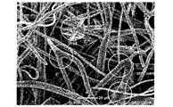
- FIG. 10 is an enlarged photograph of the surface of the fiber structure of Example 4 on the fine fiber group side.
- 1 is a conceptual cross-sectional view for explaining each region of a fiber structure according to one embodiment of the present invention;
- the fiber structure of the present invention includes a thick fiber group composed of fibers A having a single fiber diameter exceeding 5 ⁇ m (hereinafter sometimes referred to as thick fiber A) and fibers having a single fiber diameter of 5 ⁇ m or less.
- a fine fiber group composed of B hereinafter sometimes referred to as fine fiber B
- the entangled region means a region having a structure in which some of the fine fibers B constituting the fine fibers are intruded into the thick fibers as shown in the elliptical frame in FIG.
- Such a structure can be obtained by performing an entanglement treatment, which will be described later.
- the fiber structure of the present invention has at least a part of the entangled region of the thick fiber group and the fine fiber group, and is different from a laminate in which the thick fiber group and the fine fiber group are simply overlapped as layers. different.
- the thick fiber group and the fine fiber group form layers respectively, and the entangled region may be provided only near the interface between the layers. may not be separated into layers, but may have entangled regions throughout the thickness direction.
- the fiber diameter of a single fiber indicates the diameter of each single fiber. Individual single fibers can be distinguished into thick fibers A and fine fibers B by using the fiber diameter of the single fibers as an index by the method described in the examples described later.
- the fiber structure is divided into 10 equal parts in the thickness direction, and defined as the first region to the tenth region from the fine fiber group side to the thick fiber group side, and the first region to the third region are defined as the region S , the fourth to seventh regions are defined as a region T, and the eighth to tenth regions are defined as a region U.
- the fine fiber group side refers to the distribution of the fine fibers B in the area obtained by dividing the fiber structure into two equal parts in the thickness direction, and the filling rate of the fine fibers B in this area is higher than that in the other area. side, and the thick fiber group side means the side opposite to the fine fiber group side.
- FIG. 3 is a conceptual cross-sectional view for explaining each region of the fiber structure of one embodiment.
- the filling rate of the fine fibers B is higher in the upper region (first region to fifth region) than in the lower region (sixth region).
- region to tenth region the upper side of the fiber structure 100 is defined as the fine fiber group side 101 and the lower side is defined as the thick fiber group side 102, and the first region, the second region, .
- the first to third regions correspond to region S
- the fourth to seventh regions correspond to region T
- the eighth to tenth regions correspond to region U, respectively.
- the filling rate of thick fibers A present in each n-th region is defined as M n A
- the filling rate of fine fibers B is defined as M n B.
- the filling rate of thick fibers A present in the entire area of is defined as MA
- the filling rate of fine fibers B is defined as MB
- the filling rate of thick fibers A present in area S, area T, and area U is defined as SA TA, and UA
- the filling rate of fine fibers B are defined as SB, TB, and UB, respectively.
- the filling ratio indicates the ratio of the volume occupied by the target fiber in the region to the volume of the region, and is a value measured by the method described in Examples below.
- M 1 A indicates the ratio of the volume occupied by the thick fibers A in the first region to the volume of the first region.
- M 2-3 A indicates the ratio of the volume occupied by the thick fibers A in the second and third regions to the total volume of the second and third regions, and is the average value of M 2 A and M 3 A equal.
- SA indicates the ratio of the volume occupied by the thick fibers A in the region S to the total volume of the region S (that is, the first region to the third region), and is the average value of M 1 A, M 2 A and M 3 A be equivalent to.
- SB may be the largest among SB, TB, and UB, and TA+TB>SA+SB>UA+UB.
- the region U side can be used as the upstream side during collection. In that case, the airflow flows in from region U, passes through region U, region T, and region S in this order, and flows out from region S. That is, such a fiber structure has a low fiber (thick fiber A and fine fiber B) filling rate in the upstream region U, and a fiber (thick fiber A and fine fiber B, especially thick fiber) in the intermediate region T It has a structure in which A) has a high filling rate and fine fibers B have a high filling rate in the downstream region S.
- Dust in gas is a mixture of particulate matter with various particle sizes.
- region U has a coarse structure with few fibers. Therefore, dust with a large particle size can be collected without causing clogging.
- the region T has a structure with a smaller mesh than the region U due to the high filling rate of the fibers (especially the thick fibers A), it collects the rest of the dust with a large particle size and Dust can be collected gradually.
- the region S has a denser structure than the region T due to the presence of the largest amount of the fine fibers B, it is possible to collect dust with a small particle size.
- the fiber structure has a gradient structure of pores that can gradually collect dust particles having a large particle size to a small particle size as it goes from the upstream side to the downstream side. is less likely to be high, and a high dust holding capacity can be achieved.
- the fiber structure of the present invention preferably has a low fiber filling rate in the region U from the viewpoint of preventing clogging on the upstream side.
- UA+UB may be 10.0% or less, preferably 8.0. % or less, more preferably 5.0% or less.
- the lower limit of UA + UB is not particularly limited, it may be 0.1% or more, preferably 0.5% or more, from the viewpoint of allowing dust with a large particle size to be collected to some extent. may
- the fiber filling rate (TA+TB) in the region T may be 6.0 to 30.0% from the viewpoint of improving the collection efficiency while preventing clogging in the intermediate region. , preferably 6.2 to 25.0%, more preferably 6.5 to 20.0%.
- the filling rate of the fine fibers B in the region S is preferably high from the viewpoint of improving the efficiency of collecting dust with a small particle size on the downstream side.
- the maximum M n B may be 5.0% or more, preferably 5.5% or more, and more preferably 6.0% or more.
- the upper limit of the maximum M n B among M 1 B, M 2 B and M 3 B is not particularly limited, but from the viewpoint of reducing pressure loss, for example, it may be 25.0% or less, preferably may be 18.0% or less, more preferably 15.0% or less.
- the fiber structure of the present invention may have SB+UA of 1.0 to 12.0%, preferably 2.0 to 11.5%, more preferably 2.5%. It may be up to 11.0%.
- thick fibers A are present in the region S on the side of the fine fiber group to provide an entangled region. It may be present, preferably 0.08 to 15.0%, more preferably 0.10 to 10.0%.
- the entangled region may be regarded as a region in which both the thick fibers A and the fine fibers B are present among the first to tenth regions.
- a ratio M n A/M n B between the filling rate of the thick fibers A and the filling rate of the fine fibers B present in the region may be 0.1 to 200.
- the fiber structure of the present invention preferably has a wide range of entangled regions in the thickness direction. 4) adjacent regions, M n A/M n B may be preferably 0.2-100, more preferably 0.5-80, even more preferably 1-70.
- the fiber filling rate MA + MB of the entire region of the first region to the tenth region is 1.0 to 20.0% well, preferably 3.0 to 18.0%, more preferably 5.0 to 15.0%.
- the ratio MA/MB between the filling rate of the thick fibers A and the filling rate of the fine fibers B in the entire region of the first region to the tenth region may be 0.5 to 10, It may be preferably 0.8-8, more preferably 1.10-6, still more preferably 2.25-5.
- the average number of fusion points between the fine fibers B in 100 ⁇ m ⁇ 100 ⁇ m in the plane direction of the fiber structure may be 1.0 or more and 10.0 or less.
- fusion means a state in which at least part of the fibers are melted and the fibers are bonded to each other.
- the number of fused points between the fine fibers B in the plane direction of 100 ⁇ m ⁇ 100 ⁇ m of the fiber structure means that the number of fine fibers B that can be confirmed in a plane enlarged image of the range of 100 ⁇ m ⁇ 100 ⁇ m in the plane direction of the fiber structure by a microscope is as shown in FIG. This is the number of fused points at intersections as indicated by the circles.
- the average number of fusion bonding points is the average value of the number of fusion bonding points in 100 ⁇ m ⁇ 100 ⁇ m at five different locations in the plane direction of the fiber structure, and is a value measured by the method described in Examples below.
- it is the number of fused points that can be confirmed in the enlarged image, not only the surface of the fiber structure of 100 ⁇ m ⁇ 100 ⁇ m in the plane direction but also the range in the thickness direction displayed in the enlarged image is included.
- the fine fiber groups are less fixed by fusion and are bonded by mechanical entanglement, so the fine fiber groups have an increased degree of freedom. Allows the fibers to move easily. As a result, the fine fiber group is easily entangled with the thick fiber group at the time of entangling, which will be described later. On the other hand, if the average number of fusion bonding points between the fine fibers B is too small, the degree of freedom of the fine fiber group becomes too large. As a result, it becomes difficult to entangle with the thick fiber group, probably because the fine fiber group escapes and is pushed aside at the time of entangling.
- the fiber structure in which the average number of fusion points between the fine fibers B is within a specific range. is a state in which the fine fiber group and the thick fiber group are easily entangled, so that while the fine fiber B remains on the fine fiber group side, many fibers are distributed in the inner area in the thickness direction. It is believed that the dust holding capacity can be increased as a result.
- the average number of fusion bonding points between the fine fibers B may be preferably 8.0 or less, more preferably 5.0 or less.
- the fusion points between the fine fibers B may be derived from the fusion by the melt blow method.
- the meltblowing method is preferable in that the fibers can be thinned, but it is a nonwoven fabric manufacturing method that utilizes the self-bonding properties of the fibers. From the viewpoint of improving the flexibility of the fibers with respect to air currents, it is preferable that the average number of fusion bonding points between the fine fibers B produced by the meltblowing method is within a specific range.
- the fiber structure of the present invention is an entangled product of a thick fiber nonwoven fabric (preferably meltblown nonwoven fabric or spunlace nonwoven fabric) formed from thick fibers A and a fine fiber nonwoven fabric (preferably meltblown nonwoven fabric) formed from fine fibers B.
- a thick fiber nonwoven fabric preferably meltblown nonwoven fabric or spunlace nonwoven fabric
- a fine fiber nonwoven fabric preferably meltblown nonwoven fabric
- the fine fibers B may be long fibers or short fibers, and the fiber length may be 15 mm or more, preferably 20 mm or more, more preferably 30 mm. 35 mm or more, more preferably 35 mm or more.
- a long fiber is a fiber that constitutes a long fiber nonwoven fabric (for example, meltblown nonwoven fabric, spunbond nonwoven fabric), and is distinguished from short fibers that are cut into predetermined fiber lengths and have relatively uniform fiber lengths. can do.
- the basis weight of the fiber structure can be appropriately set according to the application. It may be about 120 g/m 2 .
- the basis weight is a value measured by the method described in Examples below.
- the apparent density of the fiber structure is, for example, about 0.005 to 0.30 g/cm 3 (for example, 0.005 to 0.10 g/cm 3 ) from the viewpoint of achieving both high collection efficiency and low pressure loss. It may be, preferably about 0.01 to 0.20 g/cm 3 (for example, 0.01 to 0.08 g/cm 3 ), more preferably about 0.02 to 0.15 g/cm 3 (for example, 0.02 to 0.07 g/cm 3 ).
- the apparent density is a value measured by the method described in Examples below.
- the thickness of the fiber structure can be appropriately set according to the application. For example, it may be about 0.1 to 5 mm, preferably about 0.2 to 3 mm, more preferably 0.3 It may be up to about 1 mm.
- the thickness is a value measured by the method described in Examples below.
- the thick fibers A refer to all fibers having a single fiber diameter exceeding 5.0 ⁇ m in the fiber structure, and the aggregate of the thick fibers A is the thick fiber group.
- the number average fiber diameter of single fibers in the thick fiber group may be 5.5 ⁇ m or more, preferably 6.0 ⁇ m or more, and more preferably 7.0 ⁇ m or more.
- the upper limit of the number average fiber diameter of the single fibers of the thick fiber group is not particularly limited, but from the viewpoint of optimizing the entanglement with the fine fiber group, it may be 50 ⁇ m or less, preferably 30 ⁇ m or less. good.
- the number-average fiber diameter of single fibers is a value measured by the method described in Examples below.
- the fine fiber B means all fibers having a single fiber diameter of 5.0 ⁇ m or less in the fiber structure, and the aggregate of the fine fiber B is the fine fiber group.
- the number average fiber diameter of single fibers in the fine fiber group may be 4.5 ⁇ m or less, preferably 4.0 ⁇ m or less, more preferably 3.0 ⁇ m or less.
- the lower limit of the number average fiber diameter of single fibers in the fine fiber group is not particularly limited, but from the viewpoint of handleability, it may be 0.1 ⁇ m or more, preferably 0.5 ⁇ m or more.
- the ratio of the number average fiber diameter of the single fibers of the fine fiber group to the number average fiber diameter of the single fibers of the thick fiber group is (fine fiber group) /(thick fiber group) may be, for example, 0.05 to 0.80, preferably 0.08 to 0.50, and more preferably 0.10 to 0.35.
- the thick fiber A that constitutes the thick fiber group can be selected according to the application, and any of natural fibers, regenerated fibers, semi-synthetic fibers, and synthetic fibers can be used. Specifically, natural fibers such as cotton, hemp, wool, and pulp; regenerated fibers such as rayon, polynosic, and cupra; semi-synthetic fibers such as acetate and triacetate; and polyolefin resins such as polyethylene and polypropylene.
- natural fibers such as cotton, hemp, wool, and pulp
- regenerated fibers such as rayon, polynosic, and cupra
- semi-synthetic fibers such as acetate and triacetate
- polyolefin resins such as polyethylene and polypropylene.
- Fibers polystyrene fibers formed from polystyrene resins such as polystyrene, polyester fibers formed from polyester resins such as polyethylene terephthalate, polybutylene terephthalate, polytrimethylene terephthalate, polylactic acid, polyamide 6, polyamide 66, polyamide 11, Polyamide fibers formed from polyamide resins such as polyamide 12, polyamide 610 and polyamide 612, polycarbonate fibers formed from polycarbonate resins, polyurethane fibers formed from polyurethane resins, acrylics such as polyacrylonitrile Synthetic fibers such as acrylic fibers formed from system resins and various heat-resistant fibers can be used. These fibers may be used alone or in combination of two or more.
- the thick fiber A may be a non-composite fiber or a composite fiber (core-sheath type composite fiber, sea-island type composite fiber, side-by-side type composite fiber, etc.).
- conjugated fibers for example, conjugated fibers having a low melting point resin as one component (eg, a sheath component, a sea component, etc.) and a high melting point resin as another component (eg, a core component, an island component, etc.) are preferable.
- the low-melting point resin and the high-melting point resin can be appropriately selected from the above-described fiber-forming resins depending on the processing temperature of the thermal bond.
- polyolefin fibers polyolefin fibers, polyester fibers, acrylic fibers, heat-resistant fibers, and composite fibers thereof are preferably used.
- the heat-resistant fiber may be a fiber composed of a heat-resistant polymer having units having structures such as aromatic, heterocyclic, sulfur-containing, and nitrogen-containing structures in the polymer molecule, for example, polyether ether ketone (PEEK) fiber, polyether ketone (PEK) fiber, polyether ketone ketone (PEKK) fiber, polyphenylene sulfide (PPS) fiber, aromatic polyamide fiber (for example, composed of aliphatic diamine units and aromatic dicarboxylic acid units polyamide fiber), aramid fiber (para-aramid fiber, meta-aramid fiber), polyimide (PI) fiber, polyetherimide (PEI) fiber, polyamideimide fiber, amorphous polyarylate fiber, liquid crystalline polyester fiber, polybenzoxazole (PBO) fibers, polybenzimidazole (PBI) fibers, polybenzothiazole fibers, polytetrafluoroethylene (PTFE) fibers, melamine fibers, novoloid fibers, and the
- liquid crystalline polyester fibers liquid crystalline polyester fibers, polyetherimide fibers, polyphenylene sulfide fibers, and semi-aromatic polyamide fibers (for example, dicarboxylic acid units containing terephthalic acid units) are preferred from the viewpoint of melt spinnability and heat resistance.
- the fine fibers B constituting the fine fiber group can be appropriately selected according to the manufacturing method, but synthetic fibers are preferably used.
- resins constituting synthetic fibers include polyolefin-based resins, polystyrene-based resins, acrylic-based resins, polyvinyl alcohol-based resins, polyvinyl chloride-based resins, polyvinylidene chloride-based resins, polyurethane-based resins, polyester-based resins, polyether system resins, polyamide system resins, resins constituting the heat-resistant fibers used in the group of thick fibers described above, thermoplastic elastomers, and the like. These resins may be used alone or in combination of two or more.
- the fine fibers B may be fibers made of the same kind of resin as the thick fibers A, or may be fibers made of a different kind of resin. From the viewpoint of collection performance, the fine fibers B are preferably hydrophobic fibers. Further, both the thick fibers A and fine fibers B are preferably hydrophobic fibers.
- liquid crystalline polyester polyetherimide, polyphenylene sulfide, semi-aromatic polyamide (e.g., dicarboxylic acid unit but contains terephthalic acid units and the diamine units contain 1,9-nonanediamine units and/or 2-methyl-1,8-octanediamine units).
- semi-aromatic polyamide e.g., dicarboxylic acid unit but contains terephthalic acid units and the diamine units contain 1,9-nonanediamine units and/or 2-methyl-1,8-octanediamine units.
- the fiber structure of the present invention may include, for example, at least a step of preparing a laminate of a thick fiber nonwoven fabric and a fine fiber nonwoven fabric, and a step of subjecting the laminate to an entanglement treatment.
- a laminate of thick fiber nonwoven fabric and fine fiber nonwoven fabric is prepared.
- the thick fiber nonwoven fabric and the fine fiber nonwoven fabric constituting the laminate may be separately prepared and laminated to form a laminate.
- the other nonwoven fabric for example, a fine fiber nonwoven fabric
- the laminate is preferably in a state in which the two are simply overlapped (adhesive-free) without bonding. In that case, it is preferable that the fibers constituting the thick fiber nonwoven fabric and the fine fiber nonwoven fabric are not fused to each other in the resulting fiber structure.
- the thick fiber nonwoven fabric before entanglement may have a single fiber number average fiber diameter of 5.5 ⁇ m or more, preferably 6.0 ⁇ m or more, and more preferably 7.0 ⁇ m or more.
- the upper limit of the number average fiber diameter of single fibers is not particularly limited, but may be, for example, 50 ⁇ m or less, preferably 30 ⁇ m or less.
- the thick fiber nonwoven fabric may be mainly (for example, 60% by weight or more) composed of thick fibers A having a single fiber diameter exceeding 5.0 ⁇ m.
- the type of the thick fiber nonwoven fabric is not particularly limited, and can be a dry nonwoven fabric, a directly spun nonwoven fabric (e.g., meltblown nonwoven fabric, spunbonded nonwoven fabric, etc.). Non-woven fabric) and the like are preferably used. You may use a thick fiber nonwoven fabric individually or in combination of 2 or more types.
- a web is formed from a predetermined fiber assembly by a carding method or an airlaid method.
- the resulting web is then fiber-bonded to provide useful strength.
- a bonding method chemical bonding (e.g., chemical bonding method), thermal bonding (e.g., thermal bonding method, steam jet method), or mechanical bonding (e.g., spun lace method, needle punching method) can be used.
- thermal bonding e.g., thermal bonding method, steam jet method
- mechanical bonding e.g., spun lace method, needle punching method
- dry nonwoven fabrics include chemical bonded nonwoven fabrics, thermal bonded nonwoven fabrics, spunlace nonwoven fabrics, steam jet nonwoven fabrics, needle punch nonwoven fabrics, and airlaid nonwoven fabrics.
- spunlace nonwoven fabric is preferable from the viewpoint of sufficient entanglement with the fine fiber nonwoven fabric.
- the fiber length of the fibers constituting the dry nonwoven fabric may be about 15 to 70 mm, preferably about 20 to 65 mm, more preferably about 30 to 60 mm, and even more preferably about 35 to 55 mm. It is possible to distinguish dry-laid nonwovens from wet-laid nonwovens (usually having a fiber length of 10 mm or less) by such a fiber length.
- meltblown nonwoven fabrics examples include meltblown nonwoven fabrics and spunbond nonwoven fabrics.
- the meltblown nonwoven fabric is preferable because it can be adjusted to have rigidity even with a low basis weight.
- a meltblown nonwoven fabric is a nonwoven fabric obtained by a meltblowing method, and although a nonwoven fabric with a fine fineness is generally obtained by a meltblowing method, it is also possible to obtain a nonwoven fabric with a large fineness under specific manufacturing conditions.
- the meltblown nonwoven fabric is used as the thick fiber nonwoven fabric, it has high rigidity and can improve the entanglement with the fine fiber nonwoven fabric.
- the collection surface is in a thick state before the fiber stream is thinned by the melt blow method and before the fiber is solidified. It is preferred that the fibers reach the For example, it is preferable to lengthen the time until solidification by shortening the collection distance of the fiber flow by the melt-blowing method or increasing the fiber diameter by increasing the viscosity of the resin.
- the collection distance (the distance from the nozzle to the collection surface) may be in the range of 3 to 100 cm, preferably 5 to 80 cm, and more preferably 7 to 60 cm.
- the fibers constituting the thick fiber nonwoven fabric may be long fibers from the viewpoint of improving rigidity and sufficiently entangling with the fine fiber nonwoven fabric.
- the basis weight of the thick fiber nonwoven fabric may be, for example, about 10 to 150 g/m 2 , preferably about 12 to 130 g/m 2 , more preferably about 15 to 100 g/m 2 .
- the thick fiber nonwoven fabric preferably has a relatively coarse structure from the viewpoint of sufficient entanglement with the fine fiber nonwoven fabric, and its apparent density is, for example, about 0.005 to 0.20 g/cm 3 (for example, 0 0.005 to 0.07 g/cm 3 ), preferably about 0.01 to 0.15 g/cm 3 (for example, 0.01 to 0.06 g/cm 3 ), more preferably 0.02 It may be about 0.10 g/cm 3 (for example, 0.02 to 0.05 g/cm 3 ).
- the thickness of the thick fiber nonwoven fabric may be, for example, about 0.1 to 5 mm, preferably about 0.2 to 3 mm, and more preferably about 0.3 to 1 mm.
- the fine fiber nonwoven fabric before entanglement may have a single fiber number average fiber diameter of 4.5 ⁇ m or less, preferably 4.0 ⁇ m or less, and more preferably 3.0 ⁇ m or less.
- the lower limit of the number average fiber diameter of single fibers is not particularly limited, but may be, for example, 0.1 ⁇ m or more, preferably 0.5 ⁇ m or more.
- the fine fiber nonwoven fabric may be mainly (for example, 60% by weight or more) formed of fine fibers B having a single fiber diameter of 5.0 ⁇ m or less.
- Fine fiber nonwoven fabrics include meltblown nonwoven fabrics, electrospun nonwoven fabrics, and nonwoven fabrics obtained from split fibers (fine fibers obtained by first forming a nonwoven fabric from fibers consisting of bundles of different components and splitting the fibers from the interfaces of different components).
- nonwoven fabric nonwoven fabric obtained from sea-island fibers (fine fiber nonwoven fabric obtained by eluting the sea portion of a nonwoven fabric formed of sea-island fibers), nonwoven fabric made of fibril fibers
- a fine-fiber nonwoven fabric obtained by giving and fibrillating fibers) can be used, and a meltblown nonwoven fabric is preferably used from the viewpoint of ease of entangling.
- a fine fiber nonwoven fabric in which the average number of fusion bonding points between the fine fibers B is within a specific range.
- a fine fiber nonwoven fabric By using such a fine fiber nonwoven fabric, it is possible to easily entangle the fine fiber group and the thick fiber group by performing an entanglement treatment with the thick fiber nonwoven fabric.
- a meltblown nonwoven fabric is formed by blowing hot air onto a molten thermoplastic polymer extruded from a nozzle to make it finer into fibers, entangling the fibers in a high-temperature, high-speed air stream, and simultaneously fusing them together.
- the collection distance of the fiber flow by the melt blow method by adjusting the collection distance of the fiber flow by the melt blow method, it is possible to control the self-bonding property of the discharged polymer until it reaches the collection surface after being fiberized. It was found that the average number of fusion bonding points between the fine fibers B in the resulting fine fiber nonwoven fabric can be adjusted. Specifically, self-bonding can be suppressed by lengthening the collection distance, while self-bonding can be promoted by shortening the collection distance.
- the collection distance (the distance from the nozzle to the collection surface) may be 35-90 cm, preferably 40-80 cm, and more preferably 40-70 cm.
- the basis weight of the fine fiber nonwoven fabric may be, for example, about 1.0 to 30 g/m 2 , preferably about 2.0 to 25 g/m 2 , more preferably about 2.0 to 25 g/m 2 . may be about 3.0 to 20 g/m 2 .
- the apparent density of the fine fiber nonwoven fabric may be, for example, about 0.01 to 0.30 g/cm 3 , preferably about 0.03 to 0.25 g/cm 3 , more preferably 0.05 to 0.3 g/cm 3 . It may be about 20 g/cm 3 .
- the thickness of the fine fiber nonwoven fabric may be, for example, about 0.01 to 0.30 mm, preferably about 0.03 to 0.25 mm, more preferably about 0.05 to 0.20 mm. good.
- the ratio W1/W2 of the basis weight W1 of the thick nonwoven fabric and the basis weight W2 of the fine fiber nonwoven fabric is set to 1.0 in order to sufficiently entangle the thick fiber nonwoven fabric and the fine fiber nonwoven fabric in the subsequent entangling step. It may be from 2 to 8.0, preferably from 1.3 to 5.0, more preferably from 1.5 to 3.5, even more preferably from 1.7 to 2.5.
- the thick fiber nonwoven fabric and the fine fiber nonwoven fabric can be entangled by using a spunlace method, a needle punching method, or the like. From the point of view, the spunlace method is preferably used.
- a high-pressure water stream (for example, 1 MPa or more) is applied to a porous support on which a laminate of a thick fiber nonwoven fabric and a fine fiber nonwoven fabric is placed, from a nozzle with fine holes. Water streams jetted and penetrated through the laminate are reflected against the substrate and their energy can entangle the fibers.
- the porous support used in the spunlace method may be either drum-type or plate-type, or may be used in combination, but it is preferable to use a plate-type porous support.
- the porosity of the porous support may be, for example, 10 to 50%, preferably 15 to 40%, more preferably 20 to 30%.
- the pore size of the porous support may be, for example, about 0.01 to 5.0 mm, preferably 0.05 to 3.0 mm, and more preferably about 0.1 to 1.0 mm.
- the water pressure of the water stream can be appropriately set according to the thickness of the laminate, and may be, for example, 1 to 10 MPa, preferably 1.5 to 9.5 MPa, more preferably 2 to 9 MPa.
- the hole diameter of the nozzle used for jetting the water stream may be, for example, about 0.05 to 0.2 mm.
- the interval between fine holes in the nozzle may be, for example, 0.3 to 5.0 mm, preferably 0.4 to 3.0 mm, more preferably 0.5 to 2.0 mm.
- the nozzles used for spraying the water stream may be provided in one or more rows, for example, the number of rows is 1 to 5, and from the viewpoint of optimizing the entanglement between the thick fiber nonwoven fabric and the fine fiber nonwoven fabric. , preferably 2-3 rows.
- the water pressure of the water stream may be different for each row. It is preferable to increase the water pressure of the water flow applied to the .
- the transfer speed of the laminate may be, for example, 1.0 to 10.0 m/min, preferably 2.0 to 9.0 m/min, more preferably 3.0 to 8.0 m/min.
- the water stream may be jetted from either the thick fiber nonwoven fabric side or the fine fiber nonwoven fabric side of the laminate, but from the viewpoint of sufficiently entangling the thick fiber nonwoven fabric and the fine fiber nonwoven fabric. Therefore, the water stream may be jetted from the fine fiber nonwoven fabric side of the laminate.
- the fiber structure may be subjected to an electrification treatment to increase the collection efficiency.
- the electrification treatment may be performed on the laminate before the entanglement treatment, or may be performed on the fiber structure subjected to the entanglement treatment.
- the charging treatment is not particularly limited as long as it can be charged, and examples thereof include a method of imparting electric charge by friction or contact, a method of irradiating active energy rays (e.g., electron beams, ultraviolet rays, X-rays, etc.), corona discharge, plasma, and the like. a method using gas discharge, a method using a high electric field, and a hydrocharging method using a polar solvent such as water.
- active energy rays e.g., electron beams, ultraviolet rays, X-rays, etc.
- a polar solvent such as water or an organic solvent (preferably water from the viewpoint of productivity such as wastewater treatment) is sprayed onto the fiber structure, vibrated while being sprayed, or applied.
- the polar solvent is permeated into the inside of the fibrous structure and electrified by sucking from one side of the fibrous structure after or while applying the polar solvent.
- the pressure of the polar solvent impinging on the fibrous structure may preferably be 0.1-5 MPa.
- the suction pressure from the bottom may preferably be 500-5000 mmH 2 O.
- the treatment time for hydrocharging may preferably be 0.001 to 5 seconds.
- the dust holding capacity of the fiber structure of the present invention may be 4.3 mg or more, preferably 4.5 mg or more, more preferably 5.0 mg or more, and even more preferably 6.0 mg or more.
- the higher the dust retention capacity, the better, and the upper limit is not particularly limited, but may be, for example, about 30 mg.
- the dust holding capacity indicates the amount of dust that can be collected until the pressure loss of the fibrous structure attached to the circular filter holder with an inner diameter of 110 mm becomes twice the initial value. It is a value measured by the method described in.
- the collection efficiency is a value measured by the method described in Examples below.
- the pressure loss (initial pressure loss) of the fiber structure of the present invention can be adjusted, for example, in the range of 0 to 30 Pa according to the design such as the fiber diameter of the fibers to be contained, but the pressure loss of the fiber structure may be, for example, about 0 to 20 Pa, preferably about 0 to 15 Pa, and more preferably about 1 to 14 Pa.
- the pressure loss is a value measured by the method described in Examples below.
- the fiber structure of the present invention has a QF value calculated according to the following formula from collection efficiency and pressure loss, for example, 0.10 or more, preferably 0.15 or more, more preferably 0.19 or more. good.
- the higher the QF value, the better, and the upper limit is not particularly limited, but may be, for example, about 2.00.
- QF value - ln (1 - collection efficiency (%) / 100) / pressure loss (Pa)
- a fiber structure for example, it can be suitably used as a filter (especially an air filter).
- Filters are, for example, filters used for masks, various air conditioning (building air conditioning, clean rooms, paint booths, etc.), automotive industry (cabin filters, etc.), general home appliances (air conditioners, air purifiers, vacuum cleaners, etc.).
- the fiber structure is used as a filter, its thick fiber group side can be used as the upstream side.
- the fiber structure of the present invention may be used as a filter sheet for masks.
- the mask of the present invention may include at least the fiber structure of the present invention as a covering portion that covers at least one of the mouth and nose of the human body.
- One of the layers may comprise a fibrous structure.
- the fiber structure may be used as an intermediate sheet disposed between the expiratory side sheet and the surface side sheet that constitute the mask.
- a mask refers to a mask that covers at least one or both of the mouth and nose (especially the nostrils) of the human body, regardless of the presence or absence of a fixing part such as a band for fixing to the face. Furthermore, the mask may cover a portion of the human body other than the mouth and nose.
- the mask of the present invention is a therapeutic mask for sleep apnea syndrome (e.g., nasal mask) used for CPAP therapy suitable for treating sleep apnea syndrome, NIPPV therapy suitable for ventilation failure, etc. , full-face mask, etc.).
- Basis weight and apparent density The basis weight (g/m 2 ) was measured according to 6.2 of JIS L 1913 "Testing methods for general nonwoven fabrics". Also, the apparent density (g/cm 3 ) was calculated by dividing the basis weight by the thickness.
- a razor (“Feather Razor S single edge", manufactured by Feather Safety Razor Co., Ltd.) is applied so that it is parallel to the thickness direction of the fiber structure or various nonwoven fabrics and perpendicular to the machine direction (MD). 10 arbitrarily selected portions were cut using a digital microscope, and each cross section was observed with a digital microscope photograph. Then, the upper end and the lower end are determined on each cut surface of the fiber structure or various nonwoven fabrics, the distance in the thickness direction from the upper end to the lower end is measured, and the average value of these 10 points is calculated. The thickness (mm) of each nonwoven fabric was obtained.
- ⁇ Image analysis conditions> The resulting three-dimensional image was analyzed using image analysis software Avizo (manufactured by Thermo Fisher Scientific) in the following procedure to measure the filling rate of various fibers in each region. After cutting the obtained 3D image of the fiber structure sample to 0.75 mm ⁇ 0.75 mm ⁇ total thickness on the image analysis software, noise was removed by the NON-LOCAL Filter function. .
- the NON-LOCAL Filter function was set under the following conditions. Spatial Standard Deviation value: 5 Intensity Standard Deviation value: 0.2 Search window value: 10 Local Neighborhood value: 3 Then, binarization was performed using the Interactive Thresholding function to extract all fibers.
- the threshold was an arbitrary value between 30,000 and 35,000 out of 65,536 gradations.
- Fibers having a specific fiber diameter were extracted from the data that had been noise-removed by the NON-LOCAL Filter process using the Fiber Tracing function.
- the Fiber Tracing function was set under the following conditions. Cylinder length value of Cylinder Correlation: Any value between 2.5 and 3.5 times the fiber diameter Angular Sampling value: 5 Mask Cylinder Radius value: any value between fiber radius +1 and fiber radius +13 Outer Cylinder Radius value: fiber radius Inner Cylinder Radius value: 0 Direction Coefficient value of Trace Correlation Lines: 0.45 Minimum Distance value: An arbitrary value between the fiber radius and the fiber diameter Also, using the Arithmetic function, subtract the fibers with a specific fiber diameter extracted by the Fiber Tracing function from the total fibers extracted by the Interactive Thresholding function, Only fibers with a fiber diameter (fine fibers B) were extracted. Using the Arithmetic function, regions other than all the fibers extracted by the Interactive Thresholding function were extracted as void
- the image data was analyzed every 7.5 ⁇ m in the thickness direction, and the volume ratio of thick fiber A/fine fiber B/void in each region was calculated.
- a region in which 0.1 vol % or more of fibers existed was taken as a measurement range as a region of the fiber structure.
- the thickness of the fiber structure measured above is L (mm)
- the above 7 Integrate all the regions of the fiber structure analyzed every 5 ⁇ m, divide the cross section into 10 layers for each L / 10 (mm) thickness, and among the obtained 10 layers, from the fine fiber group side to the thick fiber
- the filling rate of the thick fiber A and the fine fiber B in each region was calculated from the first region to the tenth region toward the group side.
- the fiber structure was cut into 1 cm ⁇ 1 cm in the plane direction to obtain a sample, and the surface of the obtained sample on the side of the fine fiber group was randomly imaged in a range of 100 ⁇ m ⁇ 100 ⁇ m using a scanning electron microscope. Then, from the obtained image, the number of locations where the fine fibers B are fused to each other is measured. value was calculated. Regarding the number of fused portions, when the same fine fibers B were fused at a plurality of portions, they were counted as different portions.
- the collection performance of the fiber structures obtained in Examples and Comparative Examples was evaluated.
- the test sample was mounted on a circular filter holder with an inner diameter of 110 mm so that the thick fiber group side was on the upstream side and the fine fiber group side was on the downstream side.
- NaCl particles with a mass median diameter of 0.26 ⁇ m were used as test particles, and the particle concentration was 15 to 20 mg/m 3 , the air volume was 32 liters/minute, and the surface velocity was 5.33 cm/second.
- Collection efficiency (%) ⁇ (X1-X2)/X1 ⁇ x 100
- a differential pressure gauge was placed between the upstream and downstream sides of the filter holder in the automatic filter efficiency detection device, and the differential pressure (pressure loss (Pa)) at an air volume of 32 liters/minute was measured.
- the collection performance of the fiber structures obtained in Examples and Comparative Examples was evaluated.
- the test sample was mounted on a circular filter holder with an inner diameter of 110 mm so that the thick fiber group side was on the upstream side and the fine fiber group side was on the downstream side.
- NaCl particles with a mass median diameter of 0.26 ⁇ m were used as test particles, and the particle concentration was 15 to 20 mg/m 3 , the air volume was 32 liters/minute, and the surface velocity was 5.33 cm/second. for 60 minutes, and the collection efficiency and pressure loss were calculated every 2 minutes by the same method as above.
- the particle collection weight for each 2 minutes was calculated by the following formula from the upstream particle concentration, air volume, and collection efficiency, and the sum up to time t was defined as the dust holding capacity.
- Particle collection weight for 2 minutes upstream particle concentration (mg/m 3 ) x air volume (liter/min) x 0.001 (m 3 /liter) x 2 (min) x collection efficiency (%)/100
- MFR polypropylene
- a thick fiber nonwoven fabric single fiber number average fiber diameter 7.2 ⁇ m, basis weight 20 g/m 2 , thickness 0.76 mm, apparent density 0.03 g/cm 3 ) was obtained.
- the fibrous structure obtained by entangling the thick fiber nonwoven fabric and the fine fiber nonwoven fabric was subjected to an electrification treatment by a hydrocharging method. Specifically, under the following conditions, water is sprayed onto the fiber structure from one surface, and then a slit-shaped suction nozzle is brought into contact with the other surface of the fiber structure to suck water. Water was permeated into the inside of the body, and after draining the water, it was allowed to dry naturally. ⁇ Water pressure: 0.4 MPa ⁇ Suction pressure: 2000 mmH 2 O ⁇ Processing time: 0.0042 seconds (speed 20m/min) Table 1 shows various evaluation results of the obtained fiber structure.
- Example 2 The thick fiber nonwoven fabric obtained in Example 1 (1) and the fine fiber nonwoven fabric obtained in Example 1 (2) were superimposed and placed on the porous support used in Example 1, At the same time as the stack was continuously transferred in the longitudinal direction at a speed of 5.0 m/min, three nozzles (adjacent Using a distance between nozzles of 20 cm), the water pressure of the high-pressure water flow injected from the nozzles in the first row is 3.0 MPa, the water pressure of the high-pressure water flow injected from the nozzles in the second row is 5.0 MPa, and the nozzles in the third row.
- the water pressure of the high-pressure water stream jetted from the nonwoven fabric was set to 10 MPa, and the high-pressure water stream was jetted from the side of the fine fiber nonwoven fabric to carry out the entanglement treatment. Subsequently, charging treatment was performed in the same manner as in Example 1 to obtain a fibrous structure in which the thick fiber nonwoven fabric and the fine fiber nonwoven fabric were entangled. Table 1 shows various evaluation results of the obtained fiber structure.
- Example 3 (1) Production of thick fiber nonwoven fabric Using 100% by weight of polypropylene fiber (NF, manufactured by Ube Exsimo Co., Ltd.) with a single fiber number average fiber diameter of 17.5 ⁇ m and a fiber length of 51 mm as raw cotton, semi-randomly using a card method Created a web. Next, the obtained semi-random web was placed on a punching drum support having a porosity of 25% and a hole diameter of 0.3 mm, and was continuously transported in the longitudinal direction at a speed of 5.0 m/min. The entanglement treatment was performed by jetting a high-pressure water stream. This produced an entangled fibrous web (nonwoven fabric).
- NF polypropylene fiber
- two nozzles having orifices with a hole diameter of 0.10 mm are provided at intervals of 0.6 mm along the width direction of the web (distance between adjacent nozzles is 20 cm).
- Spunlace treatment is performed with the water pressure of the high-pressure water jet jetted from the nozzle at 3.0 MPa and the water pressure of the high-pressure water jet jetted from the second row nozzle at 5.0 MPa.
- a fibrous nonwoven fabric (basis weight: 35 g/m 2 , thickness: 0.42 mm, apparent density: 0.08 g/cm 3 ) was obtained.
- Example 4 The thick fiber nonwoven fabric obtained in Example 3(1) and the fine fiber nonwoven fabric obtained in Example 3(2) were overlapped and placed on the porous support used in Example 1, The laminate was continuously transported in the longitudinal direction at a speed of 5.0 m/min. Then, a high-pressure water stream with a water pressure of 7.0 MPa was jetted from the side of the fine fiber nonwoven fabric to carry out the entanglement treatment. Subsequently, charging treatment was performed in the same manner as in Example 1 to obtain a fibrous structure in which the thick fiber nonwoven fabric and the fine fiber nonwoven fabric were entangled.
- Table 1 An enlarged cross-sectional photograph is shown in FIG. 1, and an enlarged surface photograph of the fine fiber group side is shown in FIG.
- Example 5 The thick fiber nonwoven fabric obtained in Example 3(1) and the fine fiber nonwoven fabric obtained in Example 3(2) were overlapped and placed on the porous support used in Example 1, At the same time as the stack was continuously transferred in the longitudinal direction at a speed of 5.0 m/min, three nozzles (adjacent Using a distance between nozzles of 20 cm), the water pressure of the high-pressure water flow injected from the nozzles in the first row is 3.0 MPa, the water pressure of the high-pressure water flow injected from the nozzles in the second row is 5.0 MPa, and the nozzles in the third row.
- the water pressure of the high-pressure water stream jetted from the nonwoven fabric was set to 10 MPa, and the high-pressure water stream was jetted from the side of the fine fiber nonwoven fabric to carry out the entanglement treatment. Subsequently, charging treatment was performed in the same manner as in Example 1 to obtain a fibrous structure in which the thick fiber nonwoven fabric and the fine fiber nonwoven fabric were entangled. Table 1 shows various evaluation results of the obtained fiber structure.
- the number average fiber diameter of the fibers was 2.5 ⁇ m
- the basis weight was 10 g/m 2
- the thickness was 0.11 mm
- the apparent density was 0.10 g/cm 3 ).
- the fiber filling rates of region S, region T, and region U have a relationship of SA + SB > TA + TB > UA + UB, and the filling rates of thick fiber A and fine fiber B is not in a specific relationship, the average number of fusion bonding points between the fine fibers B is not within a specific range, and the dust holding capacity is low.
- SB is the largest among SB, TB, and UB, and has a specific relationship of TA+TB>SA+SB>UA+UB. Within a certain range. Although these fiber structures are manufactured using the thick fiber nonwoven fabric and the fine fiber nonwoven fabric having the same average fiber diameter as in Comparative Example 1, the dust holding capacity is 1.4 times or more that of Comparative Example 1. high.
- the thick fibers A and the fine fibers B have a specific distribution in each region, and the average number of fusion bonding points between the fine fibers B is within a specific range.
- these fiber structures are manufactured using thick fiber nonwoven fabrics and fine fiber nonwoven fabrics having average fiber diameters equivalent to those of Comparative Examples 2 and 3, the dust holding capacity is 1.0% higher than that of Comparative Examples 2 and 3. .5 times higher.
- the fiber structure of the present invention has a high dust holding capacity and a long life, so it can be suitably used as various filters (especially air filters, bag filters, liquid filters).
- filters especially air filters, bag filters, liquid filters.
- it can be used as a filter for masks, air conditioning (building air conditioning, clean rooms, paint booths, etc.), automotive industry (cabin filters, etc.), general home appliances (air conditioners, air purifiers, vacuum cleaners, etc.). can.
- Thick fiber A B Thick fiber B 100 ... Fiber structure 101 ... Fine fiber group side 102 ... Thick fiber group side 1 to 10 ... 1st region to 10th region S ... Region S T... area T U ... area U Z ⁇ thickness direction
Abstract
Description
〔態様1〕
単繊維の繊維径が5μmを超える繊維Aから構成される太繊維群と、単繊維の繊維径が5μm以下の繊維Bから構成される細繊維群とを含み、前記太繊維群と前記細繊維群とが、交絡する交絡領域を備える繊維構造体であって、
前記繊維構造体を厚さ方向に10等分し、細繊維群側から太繊維群側に向けて第1領域~第10領域とし、第1領域~第3領域を示す領域S、第4領域~第7領域を示す領域T、および第8領域~第10領域を示す領域Uに存在する前記繊維Aの充填率を、それぞれSA、TA、およびUAとし、前記繊維Bの充填率を、それぞれSB、TB、およびUBとした場合、
SB、TB、およびUBのうちSBが最大であり、
TA+TB>SA+SB>UA+UBである、
繊維構造体。
〔態様2〕
態様1に記載の繊維構造体であって、繊維構造体の面方向100μm×100μm中の繊維B同士の平均融着点数が10個以下(好ましくは8個以下、より好ましくは5個以下)である、繊維構造体。
〔態様3〕
態様2に記載の繊維構造体であって、前記繊維B同士の融着点がメルトブロー法に由来する、繊維構造体。
〔態様4〕
単繊維の繊維径が5μmを超える繊維Aから構成される太繊維群と、単繊維の繊維径が5μm以下の繊維Bから構成される細繊維群とを含み、前記太繊維群と前記細繊維群とが、交絡する交絡領域を備える繊維構造体であって、
繊維構造体の面方向100μm×100μm中の、前記細繊維群を構成する繊維B同士の平均融着点数が1.0個以上10.0個以下(好ましくは1.0個以上8.0個以下、より好ましくは1.0個以上5.0個以下)である、
繊維構造体。
〔態様5〕
態様4に記載の繊維構造体であって、前記繊維B同士の融着点がメルトブロー法に由来する、繊維構造体。
〔態様6〕
態様4または5に記載の繊維構造体であって、
前記繊維構造体を厚さ方向に10等分し、細繊維群側から太繊維群側に向けて第1領域~第10領域とし、第1領域~第3領域を示す領域S、第4領域~第7領域を示す領域T、および第8領域~第10領域を示す領域Uに存在する前記繊維Aの充填率を、それぞれSA、TA、およびUAとし、前記繊維Bの充填率を、それぞれSB、TB、およびUBとした場合、
SB、TB、およびUBのうちSBが最大であり、
TA+TB>SA+SB>UA+UBである、
繊維構造体。
〔態様7〕
態様1~6のいずれか一態様に記載の繊維構造体であって、前記繊維Aで形成された太繊維不織布と前記繊維Bで形成された細繊維不織布との絡合物である、繊維構造体。
〔態様8〕
態様1~7のいずれか一態様に記載の繊維構造体であって、前記太繊維群の単繊維の数平均繊維径が5.5μm以上(好ましくは6.0μm以上、より好ましくは7.0μm以上)であり、前記細繊維群の単繊維の数平均繊維径が4.5μm以下(好ましくは4.0μm以下、より好ましくは3.0μm以下)である、繊維構造体。
〔態様9〕
態様1~8のいずれか一態様に記載の繊維構造体であって、目付が15~180g/m2(好ましくは18~150g/m2、より好ましくは20~120g/m2)である、繊維構造体。
〔態様10〕
態様1~9のいずれか一態様に記載の繊維構造体であって、帯電されている、繊維構造体。
〔態様11〕
態様1~10のいずれか一態様に記載の繊維構造体であって、捕集効率が60%以上(好ましくは70%以上、より好ましくは80%以上)である、繊維構造体。
〔態様12〕
態様1~11のいずれか一項に記載の繊維構造体であって、捕集効率および圧力損失により下記式に従って算出されるQF値が0.10以上(好ましくは0.15以上、より好ましくは0.19以上)である、繊維構造体。
QF値=-ln(1-捕集効率(%)/100)/圧力損失(Pa)
〔態様13〕
態様1~12のいずれか一態様に記載の繊維構造体を備えるフィルター。
〔態様14〕
態様13に記載のフィルターを備えるマスク。 That is, the present invention can be configured in the following aspects.
[Aspect 1]
A thick fiber group composed of fibers A having a single fiber diameter exceeding 5 μm and a fine fiber group composed of fibers B having a single fiber diameter of 5 μm or less, wherein the thick fiber group and the fine fibers the group is a fibrous structure comprising entangled regions of entanglement,
The fiber structure is divided into 10 equal parts in the thickness direction, and the first region to the tenth region are defined from the fine fiber group side to the thick fiber group side. SA, TA, and UA are the filling rates of the fibers A existing in the region T representing the 7th region and the region U representing the 8th region to the 10th region, respectively, and the filling rate of the fibers B are respectively Let SB, TB, and UB be
SB is the largest of SB, TB, and UB, and
TA+TB>SA+SB>UA+UB,
fibrous structure.
[Aspect 2]
The fiber structure according to
[Aspect 3]
The fiber structure according to aspect 2, wherein the fusion points between the fibers B are derived from a meltblowing method.
[Aspect 4]
A thick fiber group composed of fibers A having a single fiber diameter exceeding 5 μm and a fine fiber group composed of fibers B having a single fiber diameter of 5 μm or less, wherein the thick fiber group and the fine fibers the group is a fibrous structure comprising entangled regions of entanglement,
The average number of fusion points between the fibers B constituting the fine fiber group in the plane direction of 100 μm × 100 μm of the fiber structure is 1.0 or more and 10.0 or less (preferably 1.0 or more and 8.0) below, more preferably 1.0 or more and 5.0 or less),
fibrous structure.
[Aspect 5]
The fiber structure according to aspect 4, wherein the fusion points between the fibers B are derived from a meltblowing method.
[Aspect 6]
The fiber structure according to aspect 4 or 5,
The fiber structure is divided into 10 equal parts in the thickness direction, and the first region to the tenth region are defined from the fine fiber group side to the thick fiber group side. SA, TA, and UA are the filling rates of the fibers A existing in the region T representing the 7th region and the region U representing the 8th region to the 10th region, respectively, and the filling rate of the fibers B are respectively Let SB, TB, and UB be
SB is the largest of SB, TB, and UB, and
TA+TB>SA+SB>UA+UB,
fibrous structure.
[Aspect 7]
The fiber structure according to any one of
[Aspect 8]
The fiber structure according to any one of
[Aspect 9]
The fiber structure according to any one of
[Aspect 10]
The fibrous structure according to any one of aspects 1-9, wherein the fibrous structure is electrically charged.
[Aspect 11]
The fibrous structure according to any one of
[Aspect 12]
The fiber structure according to any one of
QF value = - ln (1 - collection efficiency (%) / 100) / pressure loss (Pa)
[Aspect 13]
A filter comprising the fiber structure according to any one of aspects 1-12.
[Aspect 14]
A mask comprising a filter according to aspect 13.
QF値=-ln(1-捕集効率(%)/100)/圧力損失(Pa) The fiber structure of the present invention has a QF value calculated according to the following formula from collection efficiency and pressure loss, for example, 0.10 or more, preferably 0.15 or more, more preferably 0.19 or more. good. The higher the QF value, the better, and the upper limit is not particularly limited, but may be, for example, about 2.00.
QF value = - ln (1 - collection efficiency (%) / 100) / pressure loss (Pa)
走査型電子顕微鏡を用いて繊維構造体の表面を観察した。電子顕微鏡写真より繊維を無作為に選択し、単繊維側面から繊維径を測定し、繊維直径が5.0μmを超える繊維を太繊維Aとして数平均繊維径(n=100)を算出し、繊維直径が5.0μm以下の繊維を細繊維Bとして数平均繊維径(n=100)を算出した。 [Number average fiber diameter of single fiber]
The surface of the fibrous structure was observed using a scanning electron microscope. Randomly select fibers from the electron micrograph, measure the fiber diameter from the side of the single fiber, consider the fiber with a fiber diameter exceeding 5.0 μm as thick fiber A, and calculate the number average fiber diameter (n = 100). The number average fiber diameter (n=100) was calculated by regarding fibers with a diameter of 5.0 μm or less as fine fibers B.
JIS L 1913「一般不織布試験方法」の6.2に準じて、目付(g/m2)を測定した。また、見かけ密度(g/cm3)は、目付を厚さで除することにより、算出した。 [Base weight and apparent density]
The basis weight (g/m 2 ) was measured according to 6.2 of JIS L 1913 "Testing methods for general nonwoven fabrics". Also, the apparent density (g/cm 3 ) was calculated by dividing the basis weight by the thickness.
繊維構造体または各種不織布の厚さ方向に対して平行に、かつ機械方向(MD)に対して垂直となるように、剃刀(「フェザー剃刀S片刃」、フェザー安全剃刀(株)社製)を用いて任意の10カ所を切断し、デジタル顕微鏡での写真にてそれぞれの断面を観察した。そして、繊維構造体または各種不織布の各切断面において上端および下端を決定し、上端から下端までの厚さ方向の距離を測定し、これら10カ所の平均値を算出することにより、繊維構造体および各種不織布の厚さ(mm)を求めた。 [thickness]
A razor ("Feather Razor S single edge", manufactured by Feather Safety Razor Co., Ltd.) is applied so that it is parallel to the thickness direction of the fiber structure or various nonwoven fabrics and perpendicular to the machine direction (MD). 10 arbitrarily selected portions were cut using a digital microscope, and each cross section was observed with a digital microscope photograph. Then, the upper end and the lower end are determined on each cut surface of the fiber structure or various nonwoven fabrics, the distance in the thickness direction from the upper end to the lower end is measured, and the average value of these 10 points is calculated. The thickness (mm) of each nonwoven fabric was obtained.
繊維構造体を面方向2.5cm×2.5cmに、任意の5カ所で切り出してサンプルを採取した後、各サンプルについて下記条件でX線CT測定して3次元画像を得た。
<X線CT測定条件>
測定装置:Xradia 520 Versa(カールツァイス社製)
X線ターゲット:タングステン
X線源強度:160kV
出力:10W
対物レンズ:4X
撮影視野範囲:1512μm
ピクセルサイズ:1.5μm/pix
ビニング:2
露光時間:2秒/枚
撮影枚数:3201枚
撮像時間:4時間 [Fiber filling rate]
After the fiber structure was cut out at arbitrary five locations in the plane direction of 2.5 cm×2.5 cm and samples were collected, each sample was subjected to X-ray CT measurement under the following conditions to obtain a three-dimensional image.
<X-ray CT measurement conditions>
Measuring device: Xradia 520 Versa (manufactured by Carl Zeiss)
X-ray target: Tungsten X-ray source intensity: 160 kV
Output: 10W
Objective lens: 4X
Field of view range: 1512 μm
Pixel size: 1.5 μm/pix
Binning: 2
Exposure time: 2 seconds/frame Number of shots: 3201 shots Imaging time: 4 hours
得られた3次元画像を以下の手順で画像解析ソフトAvizo(サーモフィッシャーサイエンティフィック社製)を用いて画像解析することにより各領域の各種繊維の充填率を測定した。
得られた3次元画像を画像解析ソフトウェア上で、繊維構造体サンプルの3次元画像を0.75mm×0.75mm×全厚さになるようカットした後、NON-LOCAL Filter機能によりノイズを除去した。NON-LOCAL Filter機能は、以下の条件に設定した。
Spatial Standard Deviation値:5
Intensity Standard Deviation値:0.2
Search window値:10
Local Neighborhood値:3
そして、Interactive Thresholding機能で二値化を行い、全ての繊維を抽出した。閾値は65536階調のうち30000~35000の任意の値とした。 <Image analysis conditions>
The resulting three-dimensional image was analyzed using image analysis software Avizo (manufactured by Thermo Fisher Scientific) in the following procedure to measure the filling rate of various fibers in each region.
After cutting the obtained 3D image of the fiber structure sample to 0.75 mm × 0.75 mm × total thickness on the image analysis software, noise was removed by the NON-LOCAL Filter function. . The NON-LOCAL Filter function was set under the following conditions.
Spatial Standard Deviation value: 5
Intensity Standard Deviation value: 0.2
Search window value: 10
Local Neighborhood value: 3
Then, binarization was performed using the Interactive Thresholding function to extract all fibers. The threshold was an arbitrary value between 30,000 and 35,000 out of 65,536 gradations.
Cylinder CorrelationのCylinder length値:繊維直径の2.5~3.5倍の間の任意の値
Angular Sampling値:5
Mask Cylinder Radius値:繊維半径+1~繊維半径+13の間の任意の値
Outer Cylinder Radius値:繊維半径
Inner Cylinder Radius値:0
Trace Correlation LinesのDirection Coefficient値:0.45
Minimum Distance値:繊維半径~繊維直径の間の任意の値
また、Arithmetic機能を用い、Interactive Thresholding機能で抽出した全繊維から、Fiber Tracing機能で抽出した特定の繊維直径を有する繊維を差し引き、別の繊維直径を有する繊維(細繊維B)のみを抽出した。
Arithmetic機能を用い、Interactive Thresholding機能で抽出した全繊維以外の領域を空隙として抽出した。 Fibers having a specific fiber diameter (thick fibers A) were extracted from the data that had been noise-removed by the NON-LOCAL Filter process using the Fiber Tracing function. The Fiber Tracing function was set under the following conditions.
Cylinder length value of Cylinder Correlation: Any value between 2.5 and 3.5 times the fiber diameter Angular Sampling value: 5
Mask Cylinder Radius value: any value between fiber radius +1 and fiber radius +13 Outer Cylinder Radius value: fiber radius Inner Cylinder Radius value: 0
Direction Coefficient value of Trace Correlation Lines: 0.45
Minimum Distance value: An arbitrary value between the fiber radius and the fiber diameter Also, using the Arithmetic function, subtract the fibers with a specific fiber diameter extracted by the Fiber Tracing function from the total fibers extracted by the Interactive Thresholding function, Only fibers with a fiber diameter (fine fibers B) were extracted.
Using the Arithmetic function, regions other than all the fibers extracted by the Interactive Thresholding function were extracted as voids.
上記で測定した繊維構造体の厚さがL(mm)である場合、この厚さを10等分して1分割領域あたりの厚さがL/10(mm)となるように、上記の7.5μm毎に解析した繊維構造体の領域を全て統合し、断面をL/10(mm)厚さ毎に10階層分に分割し、得られた10階層分のうち細繊維群側から太繊維群側に向けて第1領域~第10領域とし、各領域における太繊維A、細繊維Bの充填率を算出した。
同一繊維構造体サンプル(2.5cm×2.5cm)内において、0.75mm×0.75mm×全厚さの解析範囲を125μmピッチで、上記解析条件において10カ所解析した。測定結果は、全5サンプルに対して10カ所、計50点の平均値とした。
さらに、得られた10階層分のうち細繊維群側から太繊維群側に向けて第1領域~第10領域とし、第1領域~第3領域を示す領域Sの太繊維A、細繊維Bの充填率の平均値、第4領域~第7領域を示す領域Tの太繊維A、細繊維Bの充填率の平均値、および第8領域~第10領域を示す領域Uの太繊維A、細繊維Bの充填率の平均値をそれぞれ算出した。 Using the Regional Volume Fraction function, the image data was analyzed every 7.5 μm in the thickness direction, and the volume ratio of thick fiber A/fine fiber B/void in each region was calculated. A region in which 0.1 vol % or more of fibers existed was taken as a measurement range as a region of the fiber structure.
When the thickness of the fiber structure measured above is L (mm), the above 7 Integrate all the regions of the fiber structure analyzed every 5 μm, divide the cross section into 10 layers for each L / 10 (mm) thickness, and among the obtained 10 layers, from the fine fiber group side to the thick fiber The filling rate of the thick fiber A and the fine fiber B in each region was calculated from the first region to the tenth region toward the group side.
In the same fiber structure sample (2.5 cm×2.5 cm), 10 points were analyzed under the above analysis conditions in an analysis range of 0.75 mm×0.75 mm×total thickness at a pitch of 125 μm. The measurement result was the average value of 50 points in total, 10 points for all 5 samples.
Furthermore, among the obtained 10 layers, from the fine fiber group side to the thick fiber group side, the 1st region to the 10th region, and the thick fiber A and the fine fiber B of the region S showing the 1st region to the 3rd region the average value of the filling rate of, the average value of the filling rate of thick fibers A and fine fibers B in the region T indicating the 4th to 7th regions, and the thick fibers A in the region U indicating the 8th to 10th regions, An average value of the filling rate of the fine fibers B was calculated.
繊維構造体を面方向1cm×1cmに切り出してサンプルを採取し、走査型電子顕微鏡を用いて、得られたサンプルの細繊維群側の表面を100μm×100μmの範囲でランダムに撮像した。そして、得られた画像から、細繊維Bが互いに融着している箇所の数を測定し、これを面方向で異なる5ヶ所の100μm×100μmの範囲の画像で測定し、これらの数の平均値を算出した。なお、融着している箇所の数について、同じ細繊維B同士であっても複数箇所で融着している場合には、別の箇所として数えた。 [Average number of welding points]
The fiber structure was cut into 1 cm×1 cm in the plane direction to obtain a sample, and the surface of the obtained sample on the side of the fine fiber group was randomly imaged in a range of 100 μm×100 μm using a scanning electron microscope. Then, from the obtained image, the number of locations where the fine fibers B are fused to each other is measured. value was calculated. Regarding the number of fused portions, when the same fine fibers B were fused at a plurality of portions, they were counted as different portions.
フィルター効率自動検出装置(TSI社製、AFT8130A)を用いて、実施例及び比較例で得られた繊維構造体の捕集性能を評価した。まず、試験サンプルを太繊維群側が上流側、細繊維群側が下流側になるように、内径110mmの円のフィルターホルダーに装着した。この状態で質量中央径が0.26μmのNaCl粒子を試験粒子に用いて、試験サンプルをセットしたフィルターホルダーに粒子濃度15~20mg/m3、風量32リットル/分、面速度5.33cm/秒で10秒間流し、上流側の粒子濃度X1、下流側(濾過後)の粒子濃度X2を、レーザー式粒子検出器を用いて測定し、下記の式から捕集効率を求めた。
捕集効率(%)={(X1-X2)/X1}×100 [Collection efficiency, pressure loss, QF value]
Using an automatic filter efficiency detector (manufactured by TSI, AFT8130A), the collection performance of the fiber structures obtained in Examples and Comparative Examples was evaluated. First, the test sample was mounted on a circular filter holder with an inner diameter of 110 mm so that the thick fiber group side was on the upstream side and the fine fiber group side was on the downstream side. In this state, NaCl particles with a mass median diameter of 0.26 μm were used as test particles, and the particle concentration was 15 to 20 mg/m 3 , the air volume was 32 liters/minute, and the surface velocity was 5.33 cm/second. for 10 seconds, and the particle concentration X1 on the upstream side and the particle concentration X2 on the downstream side (after filtration) were measured using a laser particle detector, and the collection efficiency was obtained from the following equation.
Collection efficiency (%) = {(X1-X2)/X1} x 100
QF値=-ln(1-捕集効率(%)/100)/圧力損失(Pa) Then, the QF value was calculated from the obtained collection efficiency and pressure loss according to the following formula.
QF value = - ln (1 - collection efficiency (%) / 100) / pressure loss (Pa)
フィルター効率自動検出装置(TSI社製、AFT8130A)を用いて、実施例及び比較例で得られた繊維構造体の捕集性能を評価した。まず、試験サンプルを太繊維群側が上流側、細繊維群側が下流側になるように、内径110mmの円のフィルターホルダーに装着した。この状態で質量中央径が0.26μmのNaCl粒子を試験粒子に用いて、試験サンプルをセットしたフィルターホルダーに粒子濃度15~20mg/m3、風量32リットル/分、面速度5.33cm/秒で60分間流し、2分毎に捕集効率と圧力損失を上記と同様の手法により、算出した。そして、得られた数値を用いて、測定開始時の圧力損失から2倍の圧力損失になるまでの時間tを測定した。さらに、上流側の粒子濃度、風量、捕集効率から各2分間の粒子捕集重量を下記式により算出し、時間tまでの総和を粉塵保持容量とした。
2分間の粒子捕集重量=上流側の粒子濃度(mg/m3)×風量(リットル/分)×0.001(m3/リットル)×2(分)×捕集効率(%)/100 [Dust retention capacity]
Using an automatic filter efficiency detector (manufactured by TSI, AFT8130A), the collection performance of the fiber structures obtained in Examples and Comparative Examples was evaluated. First, the test sample was mounted on a circular filter holder with an inner diameter of 110 mm so that the thick fiber group side was on the upstream side and the fine fiber group side was on the downstream side. In this state, NaCl particles with a mass median diameter of 0.26 μm were used as test particles, and the particle concentration was 15 to 20 mg/m 3 , the air volume was 32 liters/minute, and the surface velocity was 5.33 cm/second. for 60 minutes, and the collection efficiency and pressure loss were calculated every 2 minutes by the same method as above. Then, using the obtained numerical value, the time t from the pressure loss at the start of measurement until the pressure loss doubles was measured. Further, the particle collection weight for each 2 minutes was calculated by the following formula from the upstream particle concentration, air volume, and collection efficiency, and the sum up to time t was defined as the dust holding capacity.
Particle collection weight for 2 minutes = upstream particle concentration (mg/m 3 ) x air volume (liter/min) x 0.001 (m 3 /liter) x 2 (min) x collection efficiency (%)/100
(1)太繊維不織布の作製
ポリプロピレン(MFR[230℃、21.18N荷重]=30g/10分)100質量部を、一般的なメルトブローン設備を使用し、紡糸温度260℃、エア温度260℃、エア流量13Nm3/min、単孔吐出量0.3g/孔・分、孔径0.4mm、孔間隔1.5mmにてノズル孔から吐出し、熱風により細化させた繊維流を捕集距離32cmで捕集することにより、太繊維不織布(単繊維の数平均繊維径7.2μm、目付20g/m2、厚さ0.76mm、見かけ密度0.03g/cm3)を得た。 [Example 1]
(1) Production of thick
ポリプロピレン(MFR[230℃、21.18N荷重]=700g/10分)100質量部に、一般的なメルトブローン設備を使用し、紡糸温度215℃、エア温度215℃、エア流量10Nm3/min、単孔吐出量0.036g/孔・分、孔径0.3mm、孔間隔0.75mm、捕集距離40cmにてメルトブロー紡糸を行い、細繊維不織布(単繊維の数平均繊維径1.2μm、目付10g/m2、厚さ0.10mm、見かけ密度0.10g/cm3)を得た。 (2) Production of fine fiber
次いで、(1)で得られた太繊維不織布と、(2)で得られた細繊維不織布とを重ね合わせた。この積層物を多孔質支持体(開孔率25%、孔径0.3mm)の上に載置し、速度5.0m/分で積層物の長手方向に連続的に移送すると同時に、孔径0.10mmのオリフィスを積層物の幅方向に沿って0.6mmの間隔で設けてあるノズル2本(隣接するノズル間の距離20cm)を使用して、1列目のノズルから噴射した高圧水流の水圧を2.0MPa、2列目のノズルから噴射した高圧水流の水圧を3.0MPaとして、細繊維不織布側から高圧水流を噴射して絡合処理を行った。 (3) Entanglement treatment of thick fiber nonwoven fabric and fine fiber nonwoven fabric Next, the thick fiber nonwoven fabric obtained in (1) and the fine fiber nonwoven fabric obtained in (2) were overlapped. This laminate was placed on a porous support (porosity of 25%, pore diameter of 0.3 mm) and continuously transported in the longitudinal direction of the laminate at a speed of 5.0 m/min. Using two nozzles (distance between adjacent nozzles: 20 cm) in which orifices of 10 mm are provided at intervals of 0.6 mm along the width direction of the laminate, the water pressure of high-pressure water jets is injected from the nozzles in the first row. was set to 2.0 MPa, and the water pressure of the high-pressure water stream jetted from the second row of nozzles was set to 3.0 MPa, and the high-pressure water stream was jetted from the fine fiber nonwoven fabric side to carry out the entangling treatment.
・水の圧力:0.4MPa
・吸引圧力:2000mmH2O
・処理時間:0.0042秒(速度20m/min)
得られた繊維構造体の各種評価結果を表1に示す。 Subsequently, the fibrous structure obtained by entangling the thick fiber nonwoven fabric and the fine fiber nonwoven fabric was subjected to an electrification treatment by a hydrocharging method. Specifically, under the following conditions, water is sprayed onto the fiber structure from one surface, and then a slit-shaped suction nozzle is brought into contact with the other surface of the fiber structure to suck water. Water was permeated into the inside of the body, and after draining the water, it was allowed to dry naturally.
・ Water pressure: 0.4 MPa
・Suction pressure: 2000 mmH 2 O
・Processing time: 0.0042 seconds (speed 20m/min)
Table 1 shows various evaluation results of the obtained fiber structure.
実施例1(1)で得られた太繊維不織布と、実施例1(2)で得られた細繊維不織布とを重ね合わせて実施例1で用いた多孔質支持体の上に載置し、速度5.0m/分で積層物の長手方向に連続的に移送すると同時に、孔径0.10mmのオリフィスを積層物の幅方向に沿って0.6mmの間隔で設けてあるノズル3本(隣接するノズル間の距離20cm)を使用して、1列目のノズルから噴射した高圧水流の水圧を3.0MPa、2列目のノズルから噴射した高圧水流の水圧を5.0MPa、3列目のノズルから噴射した高圧水流の水圧を10MPaとして、細繊維不織布側から高圧水流を噴射して絡合処理を行った。続いて、実施例1と同様に帯電処理を行い、太繊維不織布と細繊維不織布とが交絡した繊維構造体を得た。得られた繊維構造体の各種評価結果を表1に示す。 [Example 2]
The thick fiber nonwoven fabric obtained in Example 1 (1) and the fine fiber nonwoven fabric obtained in Example 1 (2) were superimposed and placed on the porous support used in Example 1, At the same time as the stack was continuously transferred in the longitudinal direction at a speed of 5.0 m/min, three nozzles (adjacent Using a distance between nozzles of 20 cm), the water pressure of the high-pressure water flow injected from the nozzles in the first row is 3.0 MPa, the water pressure of the high-pressure water flow injected from the nozzles in the second row is 5.0 MPa, and the nozzles in the third row. The water pressure of the high-pressure water stream jetted from the nonwoven fabric was set to 10 MPa, and the high-pressure water stream was jetted from the side of the fine fiber nonwoven fabric to carry out the entanglement treatment. Subsequently, charging treatment was performed in the same manner as in Example 1 to obtain a fibrous structure in which the thick fiber nonwoven fabric and the fine fiber nonwoven fabric were entangled. Table 1 shows various evaluation results of the obtained fiber structure.
(1)太繊維不織布の作製
原綿として単繊維の数平均繊維径17.5μm、繊維長51mmのポリプロピレン繊維(NF、宇部エクシモ株式会社製)100重量%を用いて、カード法を用いてセミランダムウェブを作製した。次いで、得られたセミランダムウェブを、開孔率25%、孔径0.3mmのパンチングドラム支持体上に載置し、速度5.0m/分で長手方向に連続的に移送すると同時に、上方から高圧水流を噴射して絡合処理を行った。これにより、交絡した繊維ウェブ(不織布)を製造した。この絡合処理においては、孔径0.10mmのオリフィスをウェブの幅方向に沿って0.6mmの間隔で設けてあるノズル2本を使用し(隣接するノズル間の距離20cm)、1列目のノズルから噴射した高圧水流の水圧を3.0MPa、2列目のノズルから噴射した高圧水流の水圧を5.0MPaとしてスパンレース処理を行い、さらに、裏面にして同様の絡合処理を行い、太繊維不織布(目付35g/m2、厚さ0.42mm、見かけ密度0.08g/cm3)を得た。 [Example 3]
(1) Production of thick fiber nonwoven fabric Using 100% by weight of polypropylene fiber (NF, manufactured by Ube Exsimo Co., Ltd.) with a single fiber number average fiber diameter of 17.5 μm and a fiber length of 51 mm as raw cotton, semi-randomly using a card method Created a web. Next, the obtained semi-random web was placed on a punching drum support having a porosity of 25% and a hole diameter of 0.3 mm, and was continuously transported in the longitudinal direction at a speed of 5.0 m/min. The entanglement treatment was performed by jetting a high-pressure water stream. This produced an entangled fibrous web (nonwoven fabric). In this entangling process, two nozzles having orifices with a hole diameter of 0.10 mm are provided at intervals of 0.6 mm along the width direction of the web (distance between adjacent nozzles is 20 cm). Spunlace treatment is performed with the water pressure of the high-pressure water jet jetted from the nozzle at 3.0 MPa and the water pressure of the high-pressure water jet jetted from the second row nozzle at 5.0 MPa. A fibrous nonwoven fabric (basis weight: 35 g/m 2 , thickness: 0.42 mm, apparent density: 0.08 g/cm 3 ) was obtained.
ポリプロピレン(MFR[230℃、21.18N荷重]=700g/10分)100質量部に、一般的なメルトブローン設備を使用し、紡糸温度215℃、エア温度215℃、エア量0.4MPa、単孔吐出量0.1g/孔・分、孔径0.3mm、孔間隔0.6mm(1列配置)、捕集距離40cmにてメルトブロー紡糸を行い、細繊維不織布(単繊維の数平均繊維径2.5μm、目付10g/m2、厚さ0.11mm、見かけ密度0.10g/cm3)を得た。 (2) Production of fine fiber
次いで、(1)で得られた太繊維不織布と、(2)で得られた細繊維不織布とを重ね合わせた。この積層物を実施例1で用いた多孔質支持体の上に載置し、速度5.0m/分で積層物の長手方向に連続的に移送すると同時に、孔径0.10mmのオリフィスを積層物の幅方向に沿って0.6mmの間隔で設けてあるノズル1本を使用して、水圧3.0MPaの高圧水流を細繊維不織布側から噴射して絡合処理を行った。続いて、実施例1と同様に帯電処理を行い、太繊維不織布と細繊維不織布とが交絡した繊維構造体を得た。得られた繊維構造体の各種評価結果を表1に示す。 (3) Entanglement treatment of thick fiber nonwoven fabric and fine fiber nonwoven fabric Next, the thick fiber nonwoven fabric obtained in (1) and the fine fiber nonwoven fabric obtained in (2) were overlapped. This laminate was placed on the porous support used in Example 1 and continuously transported in the longitudinal direction of the laminate at a speed of 5.0 m/min. Using one nozzle provided at intervals of 0.6 mm along the width direction of the fine fiber nonwoven fabric, a high-pressure water jet with a water pressure of 3.0 MPa was jetted from the side of the fine fiber nonwoven fabric to perform the entangling treatment. Subsequently, charging treatment was performed in the same manner as in Example 1 to obtain a fibrous structure in which the thick fiber nonwoven fabric and the fine fiber nonwoven fabric were entangled. Table 1 shows various evaluation results of the obtained fiber structure.
実施例3(1)で得られた太繊維不織布と、実施例3(2)で得られた細繊維不織布とを重ね合わせて実施例1で用いた多孔質支持体の上に載置し、速度5.0m/分で積層物の長手方向に連続的に移送すると同時に、孔径0.10mmのオリフィスを積層物の幅方向に沿って0.6mmの間隔で設けてあるノズル1本を使用して、水圧7.0MPaの高圧水流を細繊維不織布側から噴射して絡合処理を行った。続いて、実施例1と同様に帯電処理を行い、太繊維不織布と細繊維不織布とが交絡した繊維構造体を得た。得られた繊維構造体の各種評価結果を表1に示し、断面拡大写真を図1、細繊維群側の表面拡大写真を図2に示す。 [Example 4]
The thick fiber nonwoven fabric obtained in Example 3(1) and the fine fiber nonwoven fabric obtained in Example 3(2) were overlapped and placed on the porous support used in Example 1, The laminate was continuously transported in the longitudinal direction at a speed of 5.0 m/min. Then, a high-pressure water stream with a water pressure of 7.0 MPa was jetted from the side of the fine fiber nonwoven fabric to carry out the entanglement treatment. Subsequently, charging treatment was performed in the same manner as in Example 1 to obtain a fibrous structure in which the thick fiber nonwoven fabric and the fine fiber nonwoven fabric were entangled. Various evaluation results of the obtained fiber structure are shown in Table 1, an enlarged cross-sectional photograph is shown in FIG. 1, and an enlarged surface photograph of the fine fiber group side is shown in FIG.
実施例3(1)で得られた太繊維不織布と、実施例3(2)で得られた細繊維不織布とを重ね合わせて実施例1で用いた多孔質支持体の上に載置し、速度5.0m/分で積層物の長手方向に連続的に移送すると同時に、孔径0.10mmのオリフィスを積層物の幅方向に沿って0.6mmの間隔で設けてあるノズル3本(隣接するノズル間の距離20cm)を使用して、1列目のノズルから噴射した高圧水流の水圧を3.0MPa、2列目のノズルから噴射した高圧水流の水圧を5.0MPa、3列目のノズルから噴射した高圧水流の水圧を10MPaとして、細繊維不織布側から高圧水流を噴射して絡合処理を行った。続いて、実施例1と同様に帯電処理を行い、太繊維不織布と細繊維不織布とが交絡した繊維構造体を得た。得られた繊維構造体の各種評価結果を表1に示す。 [Example 5]
The thick fiber nonwoven fabric obtained in Example 3(1) and the fine fiber nonwoven fabric obtained in Example 3(2) were overlapped and placed on the porous support used in Example 1, At the same time as the stack was continuously transferred in the longitudinal direction at a speed of 5.0 m/min, three nozzles (adjacent Using a distance between nozzles of 20 cm), the water pressure of the high-pressure water flow injected from the nozzles in the first row is 3.0 MPa, the water pressure of the high-pressure water flow injected from the nozzles in the second row is 5.0 MPa, and the nozzles in the third row. The water pressure of the high-pressure water stream jetted from the nonwoven fabric was set to 10 MPa, and the high-pressure water stream was jetted from the side of the fine fiber nonwoven fabric to carry out the entanglement treatment. Subsequently, charging treatment was performed in the same manner as in Example 1 to obtain a fibrous structure in which the thick fiber nonwoven fabric and the fine fiber nonwoven fabric were entangled. Table 1 shows various evaluation results of the obtained fiber structure.
(1)細繊維不織布の作製
ポリプロピレン(MFR[230℃、21.18N荷重]=700g/10分)100質量部に、一般的なメルトブローン設備を使用し、紡糸温度215℃、エア温度215℃、エア量0.4MPa、単孔吐出量0.1g/孔・分、孔径0.3mm、孔間隔0.6mm(1列配置)、捕集距離70cmにてメルトブロー紡糸を行い、細繊維不織布(単繊維の数平均繊維径2.5μm、目付10g/m2、厚さ0.11mm、見かけ密度0.10g/cm3)を得た。 [Example 6]
(1) Production of fine fiber
実施例3(1)で得られた太繊維不織布と、実施例6(1)で得られた細繊維不織布とを重ね合わせて実施例1で用いた多孔質支持体の上に載置し、速度5.0m/分で積層物の長手方向に連続的に移送すると同時に、孔径0.10mmのオリフィスを積層物の幅方向に沿って0.6mmの間隔で設けてあるノズル1本を使用して、水圧4.0MPaの高圧水流を細繊維不織布側から噴射して絡合処理を行った。続いて、実施例1と同様に帯電処理を行い、太繊維不織布と細繊維不織布とが交絡した繊維構造体を得た。得られた繊維構造体の各種評価結果を表1に示す。 (2) Entanglement treatment of thick fiber nonwoven fabric and fine fiber nonwoven fabric Placed on the porous support used in 1 and continuously transported in the longitudinal direction of the laminate at a speed of 5.0 m / min, at the same time, an orifice with a hole diameter of 0.10 mm was made along the width direction of the laminate. Using one nozzle provided at intervals of 0.6 mm, a high-pressure water jet with a water pressure of 4.0 MPa was jetted from the side of the fine fiber nonwoven fabric to carry out the entangling treatment. Subsequently, charging treatment was performed in the same manner as in Example 1 to obtain a fibrous structure in which the thick fiber nonwoven fabric and the fine fiber nonwoven fabric were entangled. Table 1 shows various evaluation results of the obtained fiber structure.
(1)細繊維不織布の作製
ポリプロピレン(MFR[230℃、21.18N荷重]=700g/10分)100質量部に、一般的なメルトブローン設備を使用し、紡糸温度215℃、エア温度215℃、エア流量10Nm3/min、単孔吐出量0.036g/孔・分、孔径0.3mm、孔間隔0.75mm、捕集距離10cmにてメルトブロー紡糸を行い、細繊維不織布(単繊維の数平均繊維径1.2μm、目付10g/m2、厚さ0.10mm、見かけ密度0.10g/cm3)を得た。 [Comparative Example 1]
(1) Production of fine fiber
実施例1(1)で得られた太繊維不織布と、比較例1(1)で得られた細繊維不織布とを重ね合わせて実施例1で用いた多孔質支持体の上に載置し、速度5.0m/分で積層物の長手方向に連続的に移送すると同時に、孔径0.10mmのオリフィスを積層物の幅方向に沿って0.6mmの間隔で設けてあるノズル2本(隣接するノズル間の距離20cm)を使用して、1列目のノズルから噴射した高圧水流の水圧を2.0MPa、2列目のノズルから噴射した高圧水流の水圧を3.0MPaとして、太繊維不織布側から高圧水流を噴射して絡合処理を行った。続いて、実施例1と同様に帯電処理を行い、太繊維不織布と細繊維不織布とが交絡した繊維構造体を得た。得られた繊維構造体の各種評価結果を表1に示す。 (2) Entanglement treatment of thick fiber nonwoven fabric and fine fiber nonwoven fabric Placed on the porous support used in 1 and continuously transported in the longitudinal direction of the laminate at a speed of 5.0 m / min, at the same time, an orifice with a hole diameter of 0.10 mm was made along the width direction of the laminate. Using two nozzles provided at an interval of 0.6 mm (distance between adjacent nozzles 20 cm), the water pressure of the high-pressure water jet jetted from the first row nozzle is 2.0 MPa, and the second row nozzle is injected. The water pressure of the high-pressure water stream was set to 3.0 MPa, and the high-pressure water stream was jetted from the thick fiber nonwoven fabric side to perform the entanglement treatment. Subsequently, charging treatment was performed in the same manner as in Example 1 to obtain a fibrous structure in which the thick fiber nonwoven fabric and the fine fiber nonwoven fabric were entangled. Table 1 shows various evaluation results of the obtained fiber structure.
(1)細繊維不織布の作製
ポリプロピレン(MFR[230℃、21.18N荷重]=700g/10分)100質量部に、一般的なメルトブローン設備を使用し、紡糸温度215℃、エア温度215℃、エア量0.4MPa、単孔吐出量0.1g/孔・分、孔径0.3mm、孔間隔0.6mm(1列配置)、捕集距離30cmにてメルトブロー紡糸を行い、細繊維不織布(単繊維の数平均繊維径2.5μm、目付10g/m2、厚さ0.11mm、見かけ密度0.10g/cm3)を得た。 [Comparative Example 2]
(1) Production of fine fiber
実施例3(1)で得られた太繊維不織布と、比較例2(1)で得られた細繊維不織布とを重ね合わせて実施例1で用いた多孔質支持体の上に載置し、速度5.0m/分で積層物の長手方向に連続的に移送すると同時に、孔径0.10mmのオリフィスを積層物の幅方向に沿って0.6mmの間隔で設けてあるノズル1本を使用して、水圧3.0MPaの高圧水流を細繊維不織布側から噴射して絡合処理を行った。続いて、実施例1と同様に帯電処理を行い、太繊維不織布と細繊維不織布とが交絡した繊維構造体を得た。得られた繊維構造体の各種評価結果を表1に示す。 (2) Entanglement treatment of thick fiber nonwoven fabric and fine fiber nonwoven fabric Placed on the porous support used in 1 and continuously transported in the longitudinal direction of the laminate at a speed of 5.0 m / min, at the same time, an orifice with a hole diameter of 0.10 mm was made along the width direction of the laminate. Using one nozzle provided at intervals of 0.6 mm, a high-pressure water jet with a water pressure of 3.0 MPa was jetted from the side of the fine fiber nonwoven fabric to carry out the entangling treatment. Subsequently, charging treatment was performed in the same manner as in Example 1 to obtain a fibrous structure in which the thick fiber nonwoven fabric and the fine fiber nonwoven fabric were entangled. Table 1 shows various evaluation results of the obtained fiber structure.
(1)細繊維不織布の作製
ポリプロピレン(MFR[230℃、21.18N荷重]=700g/10分)100質量部に、一般的なメルトブローン設備を使用し、紡糸温度215℃、エア温度215℃、エア量0.4MPa、単孔吐出量0.1g/孔・分、孔径0.3mm、孔間隔0.6mm(1列配置)、捕集距離100cmにてメルトブロー紡糸を行い、細繊維不織布(単繊維の数平均繊維径2.5μm、目付10g/m2、厚さ0.11mm、見かけ密度0.10g/cm3)を得た。 [Comparative Example 3]
(1) Production of fine fiber
実施例3(1)で得られた太繊維不織布と、比較例3(1)で得られた細繊維不織布とを重ね合わせて実施例1で用いた多孔質支持体の上に載置し、速度5.0m/分で積層物の長手方向に連続的に移送すると同時に、孔径0.10mmのオリフィスを積層物の幅方向に沿って0.6mmの間隔で設けてあるノズル1本を使用して、水圧4.0MPaの高圧水流を細繊維不織布側から噴射して絡合処理を行った。続いて、実施例1と同様に帯電処理を行い、太繊維不織布と細繊維不織布とが交絡した繊維構造体を得た。得られた繊維構造体の各種評価結果を表1に示す。 (2) Entanglement treatment of thick fiber nonwoven fabric and fine fiber nonwoven fabric Placed on the porous support used in 1 and continuously transported in the longitudinal direction of the laminate at a speed of 5.0 m / min, at the same time, an orifice with a hole diameter of 0.10 mm was made along the width direction of the laminate. Using one nozzle provided at intervals of 0.6 mm, a high-pressure water jet with a water pressure of 4.0 MPa was jetted from the side of the fine fiber nonwoven fabric to carry out the entangling treatment. Subsequently, charging treatment was performed in the same manner as in Example 1 to obtain a fibrous structure in which the thick fiber nonwoven fabric and the fine fiber nonwoven fabric were entangled. Table 1 shows various evaluation results of the obtained fiber structure.

B・・・細繊維B
100・・・繊維構造体
101・・・細繊維群側
102・・・太繊維群側
1~10・・・第1領域~第10領域
S・・・領域S
T・・・領域T
U・・・領域U
Z・・・厚さ方向 A: Thick fiber A
B... fine fiber B
100 ... Fiber structure 101 ... Fine
T... area T
U ... area U
Z・・・thickness direction
Claims (14)
- 単繊維の繊維径が5μmを超える繊維Aから構成される太繊維群と、単繊維の繊維径が5μm以下の繊維Bから構成される細繊維群とを含み、前記太繊維群と前記細繊維群とが、交絡する交絡領域を備える繊維構造体であって、
前記繊維構造体を厚さ方向に10等分し、細繊維群側から太繊維群側に向けて第1領域~第10領域とし、第1領域~第3領域を示す領域S、第4領域~第7領域を示す領域T、および第8領域~第10領域を示す領域Uに存在する前記繊維Aの充填率を、それぞれSA、TA、およびUAとし、前記繊維Bの充填率を、それぞれSB、TB、およびUBとした場合、
SB、TB、およびUBのうちSBが最大であり、
TA+TB>SA+SB>UA+UBである、
繊維構造体。 A thick fiber group composed of fibers A having a single fiber diameter exceeding 5 μm and a fine fiber group composed of fibers B having a single fiber diameter of 5 μm or less, wherein the thick fiber group and the fine fibers the group is a fibrous structure comprising entangled regions of entanglement,
The fiber structure is divided into 10 equal parts in the thickness direction, and the first region to the tenth region are defined from the fine fiber group side to the thick fiber group side. SA, TA, and UA are the filling rates of the fibers A existing in the region T representing the 7th region and the region U representing the 8th region to the 10th region, respectively, and the filling rate of the fibers B are respectively Let SB, TB, and UB be
SB is the largest of SB, TB, and UB, and
TA+TB>SA+SB>UA+UB,
fibrous structure. - 請求項1に記載の繊維構造体であって、繊維構造体の面方向100μm×100μm中の、繊維B同士の平均融着点数が、10個以下である、繊維構造体。 The fiber structure according to claim 1, wherein the average number of fusion bonding points between fibers B is 10 or less in 100 µm × 100 µm in the plane direction of the fiber structure.
- 請求項2に記載の繊維構造体であって、前記繊維B同士の融着点がメルトブロー法に由来する、繊維構造体。 The fiber structure according to claim 2, wherein the fusion points between the fibers B are derived from the meltblowing method.
- 単繊維の繊維径が5μmを超える繊維Aから構成される太繊維群と、単繊維の繊維径が5μm以下の繊維Bから構成される細繊維群とを含み、前記太繊維群と前記細繊維群とが、交絡する交絡領域を備える繊維構造体であって、
繊維構造体の面方向100μm×100μm中の、前記細繊維群を構成する繊維B同士の平均融着点数が1.0個以上10.0個以下である、
繊維構造体。 A thick fiber group composed of fibers A having a single fiber diameter exceeding 5 μm and a fine fiber group composed of fibers B having a single fiber diameter of 5 μm or less, wherein the thick fiber group and the fine fibers the group is a fibrous structure comprising entangled regions of entanglement,
The average number of fusion points between the fibers B constituting the fine fiber group is 1.0 or more and 10.0 or less in an area of 100 μm×100 μm in the plane direction of the fiber structure.
fibrous structure. - 請求項4に記載の繊維構造体であって、前記繊維B同士の融着点がメルトブロー法に由来する、繊維構造体。 The fiber structure according to claim 4, wherein the fusion point between the fibers B is derived from the meltblowing method.
- 請求項4または5に記載の繊維構造体であって、
前記繊維構造体を厚さ方向に10等分し、細繊維群側から太繊維群側に向けて第1領域~第10領域とし、第1領域~第3領域を示す領域S、第4領域~第7領域を示す領域T、および第8領域~第10領域を示す領域Uに存在する前記繊維Aの充填率を、それぞれSA、TA、およびUAとし、前記繊維Bの充填率を、それぞれSB、TB、およびUBとした場合、
SB、TB、およびUBのうちSBが最大であり、
TA+TB>SA+SB>UA+UBである、
繊維構造体。 The fiber structure according to claim 4 or 5,
The fiber structure is divided into 10 equal parts in the thickness direction, and the first region to the tenth region are defined from the fine fiber group side to the thick fiber group side. SA, TA, and UA are the filling rates of the fibers A existing in the region T representing the 7th region and the region U representing the 8th region to the 10th region, respectively, and the filling rate of the fibers B are respectively Let SB, TB, and UB be
SB is the largest of SB, TB, and UB, and
TA+TB>SA+SB>UA+UB,
fibrous structure. - 請求項1~6のいずれか一項に記載の繊維構造体であって、前記繊維Aで形成された太繊維不織布と前記繊維Bで形成された細繊維不織布との絡合物である、繊維構造体。 The fiber structure according to any one of claims 1 to 6, wherein the fiber is an entanglement of a thick fiber nonwoven fabric formed of the fiber A and a fine fiber nonwoven fabric formed of the fiber B. Structure.
- 請求項1~7のいずれか一項に記載の繊維構造体であって、前記太繊維群の単繊維の数平均繊維径が5.5μm以上であり、前記細繊維群の単繊維の数平均繊維径が4.5μm以下である、繊維構造体。 The fiber structure according to any one of claims 1 to 7, wherein the number average fiber diameter of the single fibers of the thick fiber group is 5.5 µm or more, and the number average of the single fibers of the fine fiber group A fiber structure having a fiber diameter of 4.5 μm or less.
- 請求項1~8のいずれか一項に記載の繊維構造体であって、目付が15~180g/m2である、繊維構造体。 The fiber structure according to any one of claims 1 to 8, having a basis weight of 15 to 180 g/ m2 .
- 請求項1~9のいずれか一項に記載の繊維構造体であって、帯電されている、繊維構造体。 The fiber structure according to any one of claims 1 to 9, which is electrically charged.
- 請求項1~10のいずれか一項に記載の繊維構造体であって、捕集効率が60%以上である、繊維構造体。 The fiber structure according to any one of claims 1 to 10, which has a collection efficiency of 60% or more.
- 請求項1~11のいずれか一項に記載の繊維構造体であって、捕集効率および圧力損失により下記式に従って算出されるQF値が0.10以上である、繊維構造体。
QF値=-ln(1-捕集効率(%)/100)/圧力損失(Pa) The fiber structure according to any one of claims 1 to 11, wherein the QF value calculated from the collection efficiency and pressure loss according to the following formula is 0.10 or more.
QF value = - ln (1 - collection efficiency (%) / 100) / pressure loss (Pa) - 請求項1~12のいずれか一項に記載の繊維構造体を備えるフィルター。 A filter comprising the fiber structure according to any one of claims 1 to 12.
- 請求項13に記載のフィルターを備えるマスク。 A mask comprising the filter according to claim 13.
Priority Applications (3)
| Application Number | Priority Date | Filing Date | Title |
|---|---|---|---|
| JP2023533532A JPWO2023282088A1 (en) | 2021-07-07 | 2022-06-24 | |
| CN202280048035.5A CN117642535A (en) | 2021-07-07 | 2022-06-24 | Fiber structure and use thereof |
| KR1020247001510A KR20240026178A (en) | 2021-07-07 | 2022-06-24 | Fibrous structures and their uses |
Applications Claiming Priority (4)
| Application Number | Priority Date | Filing Date | Title |
|---|---|---|---|
| JP2021-112950 | 2021-07-07 | ||
| JP2021112951 | 2021-07-07 | ||
| JP2021112950 | 2021-07-07 | ||
| JP2021-112951 | 2021-07-07 |
Publications (1)
| Publication Number | Publication Date |
|---|---|
| WO2023282088A1 true WO2023282088A1 (en) | 2023-01-12 |
Family
ID=84801036
Family Applications (1)
| Application Number | Title | Priority Date | Filing Date |
|---|---|---|---|
| PCT/JP2022/025285 WO2023282088A1 (en) | 2021-07-07 | 2022-06-24 | Fiber structure and use thereof |
Country Status (4)
| Country | Link |
|---|---|
| JP (1) | JPWO2023282088A1 (en) |
| KR (1) | KR20240026178A (en) |
| TW (1) | TW202311589A (en) |
| WO (1) | WO2023282088A1 (en) |
Citations (9)
| Publication number | Priority date | Publication date | Assignee | Title |
|---|---|---|---|---|
| JPS61272063A (en) * | 1985-05-29 | 1986-12-02 | 東レ株式会社 | Mask |
| JP2001279570A (en) * | 2000-03-30 | 2001-10-10 | Toyobo Co Ltd | Composite nonwoven fabric and method for producing the same |
| JP2008184701A (en) * | 2007-01-29 | 2008-08-14 | Japan Vilene Co Ltd | Nonwoven fabric and method for producing the same |
| JP2009101254A (en) * | 2007-10-19 | 2009-05-14 | Japan Gore Tex Inc | Air filter and air filter for cleaner using it |
| WO2012014501A1 (en) * | 2010-07-29 | 2012-02-02 | 三井化学株式会社 | Non-woven fiber fabric, and production method and production device therefor |
| JP2018178337A (en) * | 2017-04-21 | 2018-11-15 | 旭化成株式会社 | Polyphenylene sulfide nonwoven fabric |
| JP2019126520A (en) * | 2018-01-24 | 2019-08-01 | 花王株式会社 | Wiping sheet |
| WO2020137605A1 (en) | 2018-12-28 | 2020-07-02 | クラレクラフレックス株式会社 | Fiber structure and application thereof |
| WO2021010178A1 (en) | 2019-07-16 | 2021-01-21 | クラレクラフレックス株式会社 | Fiber structure and production method therefor |
-
2022
- 2022-06-24 KR KR1020247001510A patent/KR20240026178A/en unknown
- 2022-06-24 JP JP2023533532A patent/JPWO2023282088A1/ja active Pending
- 2022-06-24 WO PCT/JP2022/025285 patent/WO2023282088A1/en active Application Filing
- 2022-07-05 TW TW111125132A patent/TW202311589A/en unknown
Patent Citations (9)
| Publication number | Priority date | Publication date | Assignee | Title |
|---|---|---|---|---|
| JPS61272063A (en) * | 1985-05-29 | 1986-12-02 | 東レ株式会社 | Mask |
| JP2001279570A (en) * | 2000-03-30 | 2001-10-10 | Toyobo Co Ltd | Composite nonwoven fabric and method for producing the same |
| JP2008184701A (en) * | 2007-01-29 | 2008-08-14 | Japan Vilene Co Ltd | Nonwoven fabric and method for producing the same |
| JP2009101254A (en) * | 2007-10-19 | 2009-05-14 | Japan Gore Tex Inc | Air filter and air filter for cleaner using it |
| WO2012014501A1 (en) * | 2010-07-29 | 2012-02-02 | 三井化学株式会社 | Non-woven fiber fabric, and production method and production device therefor |
| JP2018178337A (en) * | 2017-04-21 | 2018-11-15 | 旭化成株式会社 | Polyphenylene sulfide nonwoven fabric |
| JP2019126520A (en) * | 2018-01-24 | 2019-08-01 | 花王株式会社 | Wiping sheet |
| WO2020137605A1 (en) | 2018-12-28 | 2020-07-02 | クラレクラフレックス株式会社 | Fiber structure and application thereof |
| WO2021010178A1 (en) | 2019-07-16 | 2021-01-21 | クラレクラフレックス株式会社 | Fiber structure and production method therefor |
Also Published As
| Publication number | Publication date |
|---|---|
| TW202311589A (en) | 2023-03-16 |
| JPWO2023282088A1 (en) | 2023-01-12 |
| KR20240026178A (en) | 2024-02-27 |
Similar Documents
| Publication | Publication Date | Title |
|---|---|---|
| WO2021010178A1 (en) | Fiber structure and production method therefor | |
| US7691168B2 (en) | Highly charged, charge stable nanofiber web | |
| CN101617072B (en) | An improved composite filter media with high surface area fibers | |
| AU2007356885B2 (en) | Highly charged, charge stable nanofiber web | |
| TW201902537A (en) | Mask | |
| JP7077575B2 (en) | Mixed non-woven fabrics, laminates, filter media for filters, and methods for manufacturing these | |
| CN107208336A (en) | For breathing equipment and the melt-spun filter medium of mask | |
| MXPA03001746A (en) | Integrated nonwoven laminate material. | |
| KR102477321B1 (en) | Fiber laminate | |
| US20080166938A1 (en) | Microfiber split film filter felt and method of making same | |
| KR20190130653A (en) | Nonwoven Cellulose Fiber Fabric With Customized Liquid Wicking Ability | |
| DE202007015994U1 (en) | Air filter medium | |
| CN113260750B (en) | Fiber structure and use thereof | |
| CN103801155B (en) | Highly charged and the nanometer fiber net of charge stable | |
| WO2023282088A1 (en) | Fiber structure and use thereof | |
| JP4737039B2 (en) | Filter nonwoven fabric for air intake | |
| CN112888492A (en) | Air filtration media including a re-fluff spunbond web and methods of making and using | |
| CN117642535A (en) | Fiber structure and use thereof | |
| JP4126679B2 (en) | Filter and manufacturing method thereof | |
| JP2004003065A (en) | Conjugate fiber nonwoven fabric and composite nonwoven fabric | |
| CN114126742B (en) | Fiber structure and method for producing same | |
| TW201900971A (en) | Nonwoven cellulose fiber fabric with extremely low heavy metal content | |
| JPH06259765A (en) | Cleaning sheet for magnetic recording medium | |
| JP2011184832A (en) | Filter material for fuel suction filter |
Legal Events
| Date | Code | Title | Description |
|---|---|---|---|
| 121 | Ep: the epo has been informed by wipo that ep was designated in this application |
Ref document number: 22837505 Country of ref document: EP Kind code of ref document: A1 |
|
| WWE | Wipo information: entry into national phase |
Ref document number: 2023533532 Country of ref document: JP |
|
| ENP | Entry into the national phase |
Ref document number: 20247001510 Country of ref document: KR Kind code of ref document: A |
|
| WWE | Wipo information: entry into national phase |
Ref document number: 2022837505 Country of ref document: EP |
|
| ENP | Entry into the national phase |
Ref document number: 2022837505 Country of ref document: EP Effective date: 20240207 |
|
| NENP | Non-entry into the national phase |
Ref country code: DE |