WO2023281917A1 - 光照射医療装置 - Google Patents
光照射医療装置 Download PDFInfo
- Publication number
- WO2023281917A1 WO2023281917A1 PCT/JP2022/020215 JP2022020215W WO2023281917A1 WO 2023281917 A1 WO2023281917 A1 WO 2023281917A1 JP 2022020215 W JP2022020215 W JP 2022020215W WO 2023281917 A1 WO2023281917 A1 WO 2023281917A1
- Authority
- WO
- WIPO (PCT)
- Prior art keywords
- section
- light
- optical fiber
- coil
- medical device
- Prior art date
- Legal status (The legal status is an assumption and is not a legal conclusion. Google has not performed a legal analysis and makes no representation as to the accuracy of the status listed.)
- Ceased
Links
Images









Classifications
-
- A—HUMAN NECESSITIES
- A61—MEDICAL OR VETERINARY SCIENCE; HYGIENE
- A61B—DIAGNOSIS; SURGERY; IDENTIFICATION
- A61B18/00—Surgical instruments, devices or methods for transferring non-mechanical forms of energy to or from the body
- A61B18/18—Surgical instruments, devices or methods for transferring non-mechanical forms of energy to or from the body by applying electromagnetic radiation, e.g. microwaves
- A61B18/20—Surgical instruments, devices or methods for transferring non-mechanical forms of energy to or from the body by applying electromagnetic radiation, e.g. microwaves using laser
- A61B18/22—Surgical instruments, devices or methods for transferring non-mechanical forms of energy to or from the body by applying electromagnetic radiation, e.g. microwaves using laser the beam being directed along or through a flexible conduit, e.g. an optical fibre; Couplings or hand-pieces therefor
- A61B18/24—Surgical instruments, devices or methods for transferring non-mechanical forms of energy to or from the body by applying electromagnetic radiation, e.g. microwaves using laser the beam being directed along or through a flexible conduit, e.g. an optical fibre; Couplings or hand-pieces therefor with a catheter
-
- A—HUMAN NECESSITIES
- A61—MEDICAL OR VETERINARY SCIENCE; HYGIENE
- A61N—ELECTROTHERAPY; MAGNETOTHERAPY; RADIATION THERAPY; ULTRASOUND THERAPY
- A61N5/00—Radiation therapy
- A61N5/06—Radiation therapy using light
-
- A—HUMAN NECESSITIES
- A61—MEDICAL OR VETERINARY SCIENCE; HYGIENE
- A61N—ELECTROTHERAPY; MAGNETOTHERAPY; RADIATION THERAPY; ULTRASOUND THERAPY
- A61N5/00—Radiation therapy
- A61N5/06—Radiation therapy using light
- A61N5/067—Radiation therapy using light using laser light
Definitions
- the present invention relates to a light irradiation medical device for irradiating tissues such as cancer cells with light in body lumens such as blood vessels and gastrointestinal tracts.
- a photosensitizer is administered into the body by intravenous injection or intraperitoneal injection, and the photosensitizer is accumulated in target tissues such as cancer cells, and light of a specific wavelength is used. to excite the photosensitizer.
- An energy transfer occurs when the excited photosensitizer returns to the ground state, generating reactive oxygen species.
- Target tissue can be removed by attacking the target tissue with reactive oxygen species.
- ablation using laser light a target tissue is irradiated with laser light and cauterized. An apparatus for performing such light irradiation has been proposed.
- Patent Document 1 discloses a device for laser treatment comprising an optical fiber, a flexible tube that surrounds the periphery of the optical fiber with a gap, and a holder that holds the output-side end of the optical fiber substantially coaxially within the tube.
- a fiber optic probe is disclosed. Further, it is disclosed that the holding part is composed of one coil spring, and the first cylindrical coil part of the coil spring is passed through the optical fiber and fixed to the coating of the optical fiber.
- Patent Document 2 discloses a medical light guide that includes an optical fiber and a cover tube that covers the optical fiber.
- An optical fiber has a core, a clad, and a coating covering the clad.
- the front-illumination type light irradiation device as described in Patent Document 1 emits light at a certain location, and then shifts the position of the light-emitting portion with respect to the target tissue for a while. It was necessary to perform the operation of shifting and emitting light again multiple times. In addition, irradiation may be difficult depending on the location and shape of the tumor.
- the side irradiation type light irradiation device has the advantage of being able to irradiate a wide range in the circumferential direction at once. However, in the device as described in Patent Document 2, the emission intensity distribution may be uneven in the circumferential direction of the device.
- the first object is to provide a light irradiation medical device that contributes to the efficiency of procedures.
- the side irradiation type light irradiation device described in Patent Document 2 has the advantage of being able to irradiate a wide range in the circumferential direction at once.
- the emission intensity distribution may be uneven in the circumferential direction of the device.
- a first embodiment of the light irradiation medical device of the present invention that can achieve the above first object is as follows. [1] a shaft having a longitudinally distal end and a proximal end and having a longitudinally extending lumen; an optical fiber disposed in the lumen of the shaft; a first coil member disposed in the lumen and having a wire helically wound around the distal portion of the optical fiber, the optical fiber extending longitudinally along a predetermined section of the distal portion; and a light diffusing portion that emits light outward in the radial direction of the shaft, wherein the first coil member partially covers the light diffusing portion.
- the light emitted from the light diffusing portion is reflected on the inner surface of the first coil member in the portion of the light diffusing portion covered with the first coil member. It becomes easy to diffuse in various directions from the exposed portion, which is the portion of the portion not covered with the first coil member. As a result, the emission intensity distribution of the exposed portion tends to be uniform in the circumferential direction of the shaft. As a result, it is possible to reduce the number of times the target tissue such as a tumor is irradiated and the number of times the position of the exposed portion is adjusted with respect to the target tissue, thereby improving the efficiency of the procedure.
- the optical fiber has a core extending longitudinally, the optical fiber has a first section having a first cladding disposed around the core, the optical fiber comprising an optical
- the diffusion part has a second clad that is arranged on the outer periphery of the core and has a surface roughness of the outer peripheral surface that is larger than that of the first clad, and has a second section that is located on the distal side of the first section.
- the optical fiber has a core extending longitudinally, the optical fiber has a first section having a first cladding disposed around the core, the optical fiber comprising an optical The light irradiation medical device according to any one of [1] to [5], wherein the diffusing portion has a third section that does not have a clad and is located on the distal side of the first section.
- the optical fiber has, in the light diffusing portion, a second clad that is arranged on the outer periphery of the core and has a larger surface roughness on the outer peripheral surface than the first clad, and is located on the distal side of the first section.
- a second embodiment of the light irradiation medical device of the present invention which can achieve the above second object, is as follows. [18] a shaft having a longitudinally distal end and a proximal end and having a longitudinally extending lumen; an optical fiber disposed in the lumen of the shaft; A cylindrical member disposed in the cavity and covering a portion of the distal portion of the optical fiber, and a wire disposed in the lumen of the shaft proximally of the cylindrical member and having a wire spiral around the optical fiber. and a handle connected to the proximal portion of the shaft, the optical fiber extending longitudinally through a section of the distal portion of the shaft.
- the cylindrical member has a light diffusing portion that emits light radially outward, the cylindrical member covers a portion of the light diffusing portion, and the proximal portion of the second coil member is fixed to the handle, A light irradiation medical device in which the entire second coil member is disposed in the lumen of the shaft in the longitudinal direction.
- the portion of the light diffusing portion covered by the cylindrical member reflects the light emitted from the light diffusing portion on the inner surface of the cylindrical member. It becomes easier to diffuse in various directions from the exposed portion, which is the portion not covered with the member. As a result, the emission intensity distribution of the exposed portion tends to be uniform in the circumferential direction of the shaft.
- the second coil member is arranged on the proximal side of the cylindrical member in the lumen of the shaft, and the entire second coil member is arranged in the lumen of the shaft in the longitudinal direction, torque can be easily transmitted to the distal side, and operability can be improved.
- the second coil member it becomes easier to arrange the optical fiber coaxially with the cylindrical member, and it is also possible to prevent the light diffusing part from being shifted, so the light emission intensity distribution of the exposed part in the circumferential direction of the shaft becomes more uniform.
- the proximal portion of the second coil member is fixed to the handle so that the second coil member can be fixed against longitudinal movement with respect to the optical fiber.
- the light irradiation medical device according to [28], wherein the first coil section is made of a radiopaque material, and the second coil section is made of a material that transmits radiation more easily than the first coil section. .
- the second coil member has a second coil portion that is wound in multiple layers, and a third coil portion that is located on the distal side of the second coil portion and is wound in a single layer.
- the light irradiation medical device according to any one of [18] to [29].
- the optical fiber has a core extending in a longitudinal direction, the optical fiber has a first section having a first cladding disposed around the core, the optical fiber comprising an optical
- the diffusion part has a second clad that is arranged on the outer periphery of the core and has a surface roughness of the outer peripheral surface that is larger than that of the first clad, and has a second section that is located on the distal side of the first section.
- the optical fiber has a core extending longitudinally, the optical fiber has a first section having a first cladding disposed around the core, the optical fiber comprising an optical The light irradiation medical device according to any one of [18] to [32], wherein the diffusing portion has a third section that does not have a clad and is located on the distal side of the first section.
- the light emitted from the light diffusion section is reflected on the inner surface of the first coil member in the portion of the light diffusion section that is covered with the first coil member. Therefore, the reflected light is likely to be diffused in various directions from the exposed portion, which is the portion of the light diffusing portion that is not covered with the first coil member. As a result, the emission intensity distribution of the exposed portion tends to be uniform in the circumferential direction of the shaft. As a result, it is possible to reduce the number of times the target tissue such as a tumor is irradiated and the number of times the position of the exposed portion is adjusted with respect to the target tissue, thereby improving the efficiency of the procedure.
- the light emitted from the light diffusing section is reflected on the inner surface of the cylindrical member in the portion of the light diffusing section that is covered with the cylindrical member. is easily diffused in various directions from the exposed portion, which is the portion of the light diffusing portion that is not covered with the cylindrical member.
- the emission intensity distribution of the exposed portion tends to be uniform in the circumferential direction of the shaft.
- the second coil member is arranged on the proximal side of the cylindrical member in the lumen of the shaft, and the entire second coil member is arranged in the lumen of the shaft in the longitudinal direction, torque can be easily transmitted to the distal side, and operability can be improved.
- the second coil member it becomes easier to arrange the optical fiber coaxially with the cylindrical member, and it is also possible to prevent the light diffusing part from being shifted, so the light emission intensity distribution of the exposed part in the circumferential direction of the shaft becomes more uniform.
- the proximal portion of the second coil member is fixed to the handle so that the second coil member can be fixed against longitudinal movement with respect to the optical fiber.
- FIG. 2 is an enlarged cross-sectional view (partial side view) of the distal side of the light irradiation medical device shown in FIG. 1 ;
- FIG. 3 is a cross-sectional end view of the light irradiation medical device shown in FIG. 2 taken along line III-III; 3 is a cut end view of the first coil member shown in FIG. 2.
- FIG. 5 is a cross-sectional view (partial side view) showing a modification of the light irradiation medical device shown in FIG.
- FIG. 3 is an enlarged cross-sectional view of the distal side of the optical fiber shown in FIG. 2;
- FIG. 7 is a cross-sectional view showing a modification of the optical fiber shown in FIG. 6;
- FIG. 7 is a cross-sectional view showing another modification of the optical fiber shown in FIG. 6;
- FIG. 3 is a cross-sectional view (partial side view) of a light irradiation medical device according to a second embodiment of the present invention;
- FIG. 10 is an enlarged cross-sectional view (partial side view) of the distal side of the light irradiation medical device shown in FIG. 9;
- FIG. 11 is a cross-sectional end view along line XI-XI of the light irradiation medical device shown in FIG.
- FIG. 10 11 is a cut end view of the cylindrical member shown in FIG. 10;
- FIG. 11 is a cross-sectional view (partial side view) showing a modification of the light irradiation medical device shown in FIG. 10.
- FIG. 11 is a cross-sectional view (partial side view) showing another modification of the light irradiation medical device shown in FIG. 10.
- FIG. 11 is a cross-sectional view (partial side view) showing still another modification of the light irradiation medical device shown in FIG. 10.
- FIG. 11 is an enlarged cross-sectional view of the distal side of the optical fiber shown in FIG. 10;
- FIG. 17 is a cross-sectional view showing a modification of the optical fiber shown in FIG. 16;
- FIG. 17 is a cross-sectional view showing another modification of the optical fiber shown in FIG. 16;
- a light irradiation medical device includes a shaft having a distal end and a proximal end in the longitudinal direction and having a lumen extending in the longitudinal direction; an optical fiber disposed in the lumen; a first coil member disposed in the lumen of the shaft and having a wire helically wound around the distal portion of the optical fiber;
- the gist is that the optical fiber has a light diffusing portion in a predetermined section of its distal portion, and the first coil member partially covers the light diffusing portion.
- the light emitted from the light diffusing portion is reflected on the inner surface of the first coil member in the portion of the light diffusing portion covered with the first coil member. It becomes easy to diffuse in various directions from the exposed portion, which is the portion of the portion not covered with the first coil member. As a result, the emission intensity distribution of the exposed portion tends to be uniform in the circumferential direction of the shaft. As a result, it is possible to reduce the number of times the target tissue such as a tumor is irradiated and the number of times the position of the exposed portion is adjusted with respect to the target tissue, thereby improving the efficiency of the procedure.
- a photoirradiation medical device is used in PDT and photoablation to irradiate light of a specific wavelength to the treatment area, which is the target tissue such as cancer cells, in a body lumen such as a blood vessel or digestive tract.
- the light irradiation medical device may be delivered to the treatment site alone, or may be used together with a delivery catheter or endoscope.
- a light irradiation medical device is placed inside the body through a forceps channel of the endoscope and delivered to a treatment site.
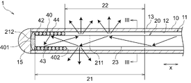
- FIG. 1 is a sectional view (partial side view) of a light irradiation medical device according to a first embodiment of the present invention.
- FIG. 2 is a cross-sectional view (partial side view) enlarging the distal side of the light irradiation medical device shown in FIG.
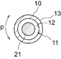
- FIG. 3 is an end view of the light irradiation medical device shown in FIG. 2 taken along line III-III. 4 is a cut end view of the first coil member shown in FIG. 2.
- FIG. FIG. 5 is a cross-sectional view (partial side view) showing a modification of the light irradiation medical device shown in FIG. FIG.
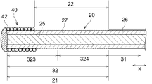
- FIG. 6 is an enlarged cross-sectional view of the distal side of the optical fiber shown in FIG. 7 and 8 are sectional views showing other modifications of the optical fiber shown in FIG.
- the light irradiation medical device 1 has a shaft 10 , an optical fiber 20 and a first coil member 40 .
- the light irradiation medical device may be simply referred to as the device.
- the shaft 10 is omitted from FIGS.
- the distal side of the device 1 refers to the distal end side of the shaft 10 in the longitudinal direction x and the treatment target side.
- the proximal side of the device 1 refers to the proximal end side of the shaft 10 in the longitudinal direction x and the user's hand side.
- the proximal side may be called the proximal portion
- the distal side may be called the distal portion.
- the inner side refers to the direction toward the central axis c extending in the longitudinal direction x of the shaft 10
- the outer side refers to the radial direction opposite to the inner side.
- the shaft 10 has a longitudinal direction x, a radial direction and a circumferential direction p. As shown in FIG. 1, shaft 10 has a distal end and a proximal end in longitudinal direction x and has a lumen 11 extending in longitudinal direction x. The shaft 10 may have only one lumen 11 or may have a plurality of them.
- the shaft 10 has a cylindrical shape for arranging the optical fiber 20 and the first coil member 40 in its lumen 11 .
- Shaft 10 preferably has a cylindrical shape with only one lumen 11 . Since the shaft 10 is inserted into the body, it is preferably flexible. Shaft 10 has an inner peripheral surface 12 and an outer peripheral surface 13 .
- the shaft 10 is a hollow body formed by arranging one or more wires in a predetermined pattern; a hollow body having at least one of its inner surface or outer surface coated with a resin; a resin tube; , such as those connected in the longitudinal direction.
- a hollow body in which wires are arranged in a predetermined pattern includes a cylindrical body having a mesh structure formed by simply crossing or weaving wires, and a coil in which wires are wound.
- the wire may be one or more solid wires or one or more twisted wires.
- a resin tube can be manufactured, for example, by extrusion molding. When the shaft 10 is a resin tube, the shaft 10 can be composed of a single layer or multiple layers.
- a portion of the shaft 10 in the longitudinal direction x or the circumferential direction p may be composed of a single layer, and the other portion may be composed of a plurality of layers.
- the shaft 10 is made of, for example, polyolefin resin (eg, polyethylene or polypropylene), polyamide resin (eg, nylon), polyester resin (eg, PET), aromatic polyether ketone resin (eg, PEEK), polyether polyamide resin, polyurethane. It can be made of synthetic resin such as resin, polyimide resin, fluorine resin (for example, PTFE, PFA, ETFE), or metal such as stainless steel, carbon steel, nickel-titanium alloy. These may be used individually by 1 type, and may be used in combination of 2 or more types. It is preferable that at least a portion of the shaft 10 that overlaps the light diffusing portion 21 is made of a resin having optical transparency. At least a portion of the shaft 10 that overlaps the light diffusing portion 21 may be made of a transparent resin.
- polyolefin resin eg, polyethylene or polypropylene
- polyamide resin eg, nylon
- polyester resin eg, PET
- aromatic polyether ketone resin eg
- a distal tip 15 may be attached to the distal end of the shaft 10 as shown in FIG. Damage to living tissue by the distal end of the shaft 10 can be avoided.
- Examples of the shape of the distal tip 15 include a cylindrical shape, an oval cylindrical shape, a hemispherical shape, an oval spherical shape, a truncated pyramid shape, a truncated cone shape, a long truncated cone shape, a rounded truncated pyramid shape, or a combination thereof. can be done.
- a handle 60 is connected to the proximal portion of the shaft 10 in FIG. By holding the handle 60 by the operator, the device 1 can be easily operated.
- the handle 60 extends, for example, in the longitudinal direction x.
- Handle 60 may be constructed from one or more members.
- the handle 60 has a hollow portion extending in the longitudinal direction x.
- the handle 60 may have, for example, a cylindrical shape.
- the shaft 10 and the optical fiber 20 are inserted through the hollow portion of the handle 60 .
- the material of the handle 60 is not particularly limited, for example, polyolefin resins such as polypropylene (PP) and polyethylene (PE), polyester resins such as polyethylene terephthalate (PET), polycarbonate resins, ABS resins, and synthetic resins such as polyurethane resins are used. be able to.
- polyolefin resins such as polypropylene (PP) and polyethylene (PE)
- PET resins such as polyethylene terephthalate (PET)
- PET polyethylene terephthalate
- polycarbonate resins polycarbonate resins
- ABS resins polyurethane resins
- the optical fiber 20 is a transmission line that transmits optical signals to the target tissue. As shown in FIGS. 1-2, optical fiber 20 is disposed within lumen 11 of shaft 10 .
- the optical fiber 20 has a light diffusing portion 21 extending in the longitudinal direction x in a predetermined section of its distal portion and emitting light outward in the radial direction of the shaft 10 .
- the light diffusing portion 21 functions as a light emitting area.
- the light diffusing portion 21 is arranged to extend in the longitudinal direction x and the circumferential direction p of the shaft 10 .
- the light diffusing portion 21 has an outer peripheral surface 23 .
- An outer peripheral surface 23 of the light diffusion portion 21 faces the inner peripheral surface 12 side of the shaft 10 .
- the proximal end of optical fiber 20 extends proximally from handle 60 .
- the proximal end of optical fiber 20 is connected to a light source such as a semiconductor laser.
- the device 1 is inserted through the endoscope to the position where the target tissue is in the body cavity. At this time, the target tissue is positioned radially outward of the outer peripheral surface 13 of the shaft 10 .
- the light emitted from the light diffusing portion 21 passes through at least a portion of the shaft 10 that overlaps the light diffusing portion 21 , so that the light reaches the target tissue around the device 1 .
- the light diffusing portion 21 From the light diffusing portion 21 , it is sufficient that light is emitted at least outward in the radial direction of the shaft 10 , and from the light diffusing portion 21 , the radial direction of the shaft 10 extends over the entire circumferential direction p of the shaft 10 . It is preferable that the light is emitted outward. Light may be emitted further from the light diffusing portion 21 toward the distal direction of the shaft 10, that is, toward the front. However, it is preferable that the device 1 does not include a device that emits light only in the distal direction of the shaft 10 from the light diffusing portion 21 .
- a part of the light diffusion part 21 is covered with the first coil member 40 as shown in FIGS.
- a portion from which light is emitted at least radially outward when the first coil member 40 is removed from the optical fiber 20 is referred to as a light diffusion portion 21 .
- the first coil member 40 partially covers the light diffusing section 21, at least one of the distal end and the proximal end of the light diffusing section 21 may be hidden by the first coil member 40 and cannot be visually recognized. , it may be difficult to grasp the positions of the distal end and the proximal end of the light diffusing portion 21 . Therefore, the positions of the distal end and the proximal end of the light diffusing portion 21 are specified with the first coil member 40 removed from the optical fiber 20 .
- the portion of the light diffusing portion 21 that is not covered with the first coil member 40 and is exposed to the shaft 10 side is called an exposed portion 22 .
- the shaft 10 it is preferable that there be no separate member between the exposed portion 22 and the shaft 10 , but any member that does not block the light emitted from the exposed portion 22 may be provided.
- the light diffusing part 21 is not a diffusing member separate from the optical fiber 20 (for example, a diffusion plate or a prism), but a part forming part of the optical fiber 20 .
- Optical fiber 20 has a core and a clad.
- the clad is arranged on the outer circumference of the core and covers a part of the radially outer side of the core.
- the light diffusion part 21 has (i) a mode in which only the core is arranged, (ii) a mode in which the core and the clad are arranged, or (iii) a part in which only the core is arranged and the other part in which the core and the clad are arranged. is preferably configured from any of the aspects in which is arranged.
- a covering material for protection may be arranged outside the clad in the radial direction, but it is preferable that the light diffusing portion 21 is not arranged with members other than the core and the clad.
- the materials that make up the core and clad are not particularly limited, and glass such as plastic, quartz glass, and fluoride glass can be used.
- the resin forming the shaft 10 contains inorganic particles such as titanium oxide, barium sulfate, and calcium carbonate, and organic particles such as crosslinked acrylic particles and crosslinked styrene particles. Light diffusing materials can be added. Light emitted from the light diffusing portion 21 is more easily diffused by the shaft 10 .
- the light diffusion part 21 is preferably arranged on the most distal side of the optical fiber 20 . This makes it easier to form the light diffusing portion 21 and increases the flexibility of the distal end portion of the optical fiber 20 .
- the length of the light diffusion portion 21 in the longitudinal direction x may be set to 1/50 or more, 1/45 or more, or 1/30 or more of the total length of the optical fiber 20 . By setting such a length, it becomes easy to irradiate the entire target tissue with a single irradiation. Also, the length of the light diffusing portion 21 in the longitudinal axis direction x may be set to 1/20 or less, 1/25 or less, or 1/30 or less of the total length of the optical fiber 20 . By setting such a length, it is possible to prevent irradiation of non-target tissues.
- the light diffusing portion 21 may be arranged only in a part of the shaft 10 in the circumferential direction p, but as shown in FIG. preferably. Since a wide range in the circumferential direction p can be irradiated at once, efficiency of the procedure can be improved.
- the optical fiber 20 has a core 25 extending in the longitudinal direction x, and the optical fiber 20 has a first clad 26 disposed around the core 25. It has one section 31 .
- the light is likely to be totally reflected at the boundary between the core 25 and the first clad 26. Therefore, in the first section 31, the light is confined within the core 25 and propagates to the distal side of the optical fiber 20. .
- one core 25 is arranged in one first clad 26 in the first section 31 .
- the optical fiber can be rephrased as a single-core optical fiber.
- the first clad 26 may be positioned radially outwardly of the optical fiber 20 in the first section 31 . That is, the first section 31 does not need to be provided with other members such as a covering material.
- the first section 31 of the optical fiber 20 may be provided with a coating material around the outer periphery of the first clad 26 . It is possible to protect the outside of the first section 31 , and it is also possible to suppress light leakage and emission to the outside in the first section 31 .
- the coating material may be a coating layer arranged on the outer peripheral surface of the first clad 26 or a sheath enclosing the first clad 26 .
- the covering material can be made of a resin such as an ultraviolet curable resin.
- the optical fiber 20 has a second clad 27 disposed on the outer periphery of the core 25 in the light diffusing portion 21 and has a surface roughness of the outer peripheral surface larger than that of the first clad 26 . It has a distally located second section 32 .
- the clad surface roughness larger in the second section 32 than in the first section 31 part of the light is confined within the core 25 and propagated to the distal side of the optical fiber 20, and the remaining light is transmitted to the second section 31. It leaks out from the clad 27 and is injected radially outward. It is preferable that the first section 31 does not emit light radially outward, or that the amount of light leakage is smaller than that of the second section 32 .
- one core 25 is preferably arranged in one second clad 27 .
- the first section 31 and the second section 32 may consist of one optical fiber.
- the first clad 26 of the first section 31 and the second clad 27 of the second section 32 may be integrally molded.
- the optical fiber 20 may be formed by joining the optical fiber for the first section 31 and the optical fiber for the second section 32 in the longitudinal axis direction x.
- the first clad 26 of the first section 31 and the second clad 27 of the second section 32 may be separately formed and then joined together.
- the second clad 27 is located on the outermost side of the optical fiber 20 in the radial direction. That is, in the second section 32, it is preferable that no member (for example, a covering material) other than the core 25 and the second clad 27 is arranged. With this configuration, light can be emitted outward in the radial direction of the shaft 10 from the second section 32 .
- the surface roughness of the outer peripheral surface of the second clad 27 in the second section 32 is greater than the surface roughness of the outer peripheral surface of the first clad 26 in the first section 31 .
- the surface roughness is the arithmetic mean roughness Ra between the reference lengths of the roughness curve in the longitudinal axis direction of the outer peripheral surface of the optical fiber 20 .
- the reference length may be set according to the magnification of the laser microscope used, and is, for example, 200 ⁇ m.
- the above arithmetic mean roughness Ra corresponds to the arithmetic mean roughness Ra specified in JIS B 0601 (2001) and is measured according to JIS B 0633 (2001).
- a measuring machine specified in JIS B 0651 (2001) for example, a laser microscope VK-X3000 manufactured by Keyence Corporation is used.
- the average value of the surface roughness of the outer peripheral surface of the second clad 27 in the second section 32 is preferably larger than the average value of the surface roughness of the outer peripheral surface of the first clad 26 in the first section 31 .
- the average value of the surface roughness is the average value of the surface roughness values of 10 or more measurement points set so as to be aligned in the longitudinal axis direction x in the section to be measured (for example, the first section 31). .
- the surface roughness of the outer peripheral surface of the second clad 27 in the proximal portion 324 is The average value is preferably smaller than the average surface roughness of the outer peripheral surface of the second clad 27 in the distal portion 323 .
- the proximal portion 324 enhances the effect of confining light within the core 25 more than the distal portion 323, while the distal portion 323 facilitates the radially outward emission of light from the second clad 27. Therefore, the emission intensity distribution of the second section 32 is easily uniformed in the longitudinal direction x.
- the second section 32 is preferably shorter than the first section 31 in the longitudinal direction x. It becomes easier to form the light diffusing portion 21, and the flexibility of the distal end portion of the optical fiber 20 can also be increased.
- the length of the second section 32 in the longitudinal direction x can be set to 1/20 or less, 1/25 or less, or 1/30 or less of the length of the first section 31 .
- the length of the second section 32 in the longitudinal axis direction x may be set to 1/50 or more, 1/45 or more, or 1/30 or more of the length of the first section 31. good.
- the average thickness of the second clad 27 in the second section 32 is preferably smaller than the average thickness of the first clad 26 in the first section 31.
- the clad thickness can be measured using a laser microscope VK-X3000 manufactured by Keyence Corporation.
- the optical fiber 20 when the optical fiber 20 has the first section 31, the optical fiber 20 has no cladding in the light diffusing portion 21 and is located distal to the first section 31. You may have the 3rd area 33 which is carrying out. Since there is no clad in the third section 33, the light from the core 25 is emitted radially outward.
- no clad exists in at least a part of the core 25 in the circumferential direction, and more preferably, no clad exists in the entire circumferential direction of the core 25.
- the core 25 is positioned radially outermost in the optical fiber 20.
- at least part of the third section 33 is preferably covered with the first coil member 40 . That is, in the third section 33, it is preferable that not only the clad but also any member (for example, covering material) other than the core 25 and the first coil member 40 is arranged.
- the outer diameter of the core 25 in the third section 33 may be a constant value, or the outer diameter of the core 25 may be a different value depending on the position in the longitudinal direction x.
- the distal end of the third section 33 is preferably at the same position as the distal end of the core 25 in the longitudinal direction x. It becomes easier to form the third section 33, and the flexibility at the distal end of the optical fiber 20 can also be increased.
- the surface roughness of the outer peripheral surface of the core 25 in the third section 33 is preferably larger than the surface roughness of the outer peripheral surface of the first clad 26 in the first section 31 . Light is likely to be confined within the core 25 in the first section 31 , and light is likely to be emitted radially outward from the core 25 in the third section 33 .
- At least one of the second section 32 and the third section 33 is preferably arranged in the light diffusion section 21, and both the second section 32 and the third section 33 may be arranged.
- a second section 32 and a third section 33 are arranged in order from the proximal side to the distal side of the light diffusing section 21 .
- the first section 31, the second section 32, and the third section 33 are adjacent to each other in the longitudinal direction x. They are adjacent, and preferably the second section 32 and the third section 33 are adjacent.
- the optical fiber 20 has a second section 32 and a third section 33
- the third section 33 is shorter than the second section 32 in the longitudinal axis direction x as shown in FIG. With this configuration, it becomes easier to uniform the emission intensity distribution of the entire exposed portion 22 in the longitudinal direction x. A mode in which the second section 32 is shorter than the third section 33 in the longitudinal direction x is also allowed.
- the length of the third section 33 in the longitudinal direction x is preferably 20% or less of the total length of the second section 32 and the third section 33, and is preferably 18% or less. More preferably, the size is 15% or less. In addition, the length of the third section 33 in the longitudinal direction x may be 5% or more, 8% or more, or 10% or more of the total length of the second section 32 and the third section 33. . This configuration makes it easier to uniformize the emission intensity distribution of the exposed portion 22 in the longitudinal direction x.
- the average value of the surface roughness of the outer peripheral surface of the second clad 27 in the second section 32 is preferably smaller than the average value of the surface roughness of the outer peripheral surface of the core 25 in the third section 33 . This configuration makes it easier to uniformize the emission intensity distribution in the longitudinal axis direction x in each of the second section 32 and the third section 33 .
- the optical fiber 20 may have only the second section 32 in the light diffusing portion 21 . That is, the optical fiber 20 does not have to have the third section 33 in the light diffusing portion 21 . Even with the configuration having only the second section 32, the emission intensity distribution of the exposed portion 22 in the longitudinal axis direction x can be made uniform. Since the core 25 is not exposed, it also has the effect of preventing damage to the optical fiber 20 due to bending of the device 1 during the procedure.
- the distal end of the second section 32 is preferably at the same position as the distal end of the core 25 in the longitudinal direction x. .
- the optical fiber 20 may have only the third section 33 in the light diffusing portion 21 . That is, the optical fiber 20 does not have to have the second section 32 in the light diffusing portion 21 . Even with the configuration having only the third section 33, the emission intensity distribution of the exposed portion 22 in the longitudinal axis direction x can be made uniform.
- the second section 32 and the third section 33 can be formed by removing the clad by etching or polishing.
- the outer peripheral surface of the second clad 27 and the outer peripheral surface of the core 25 of the third section 33 may be uneven.
- the unevenness can be formed by mechanically or chemically roughening the surface of the core 25 of the second clad 27 or the third section 33 . Examples of methods for roughening the surface include etching, blasting, a method using a scribe, a wire brush, or sandpaper.
- the light diffusing portion 21 should emit the first light beam for treatment.
- the first light beam is preferably laser light with a wavelength suitable for phototherapy such as PDT and PIT for irradiating internal tissue.
- a second targeting beam may be emitted.
- the second light beam is a light beam emitted to grasp the treatment site before the first light beam is emitted, and preferably has a lower radiant energy than the first light beam.
- the first coil member 40 is disposed in the lumen 11 of the shaft 10 and has a wire 42 spirally wound around the distal portion of the optical fiber 20. , and the first coil member 40 covers a part of the light diffusing portion 21 .
- the light emitted from the light diffusing portion 21 is reflected by the inner surface of the first coil member 40 in the portion of the light diffusing portion 21 covered with the first coil member 40, so that the reflected light becomes light. It becomes easy to diffuse in various directions from the exposed portion 22 , which is the portion of the diffusion portion 21 that is not covered with the first coil member 40 .
- FIG. 2 shows how the light traveling from the proximal side toward the distal side is directly emitted from the exposed portion 22, and after being reflected by the first coil member 40, is emitted from the exposed portion 22.
- An example of the state is indicated by a thick arrow.
- the first coil member 40 covers only part of the light diffusing section 21 and does not cover the entire light diffusing section 21 .
- the exposed portion 22 is always formed in the light diffusion portion 21 .
- the first coil member 40 is formed to extend in the longitudinal direction x of the shaft 10 .
- a direction of the first coil member 40 that is parallel to the longitudinal axis direction x of the shaft 10 is referred to as an axial direction of the first coil member 40 .
- the first coil member 40 has an inner peripheral surface 43 and an outer peripheral surface 44 .
- the inner peripheral surface 43 extends in the circumferential direction p of the shaft 10 and faces the outer peripheral surface 23 side of the optical fiber 20 .
- the outer peripheral surface 44 extends in the circumferential direction p of the shaft 10 and faces the inner peripheral surface 12 side of the shaft 10 . It is preferable that the light emitted from the light diffusing portion 21 is reflected at least by the inner peripheral surface 43 of the first coil member 40 .
- the first coil member 40 may have a shape in which the distal end 401 side is closed and the proximal end 402 side is open.
- the first coil member 40 has an outer end face 45 on the distal end 401 side and an inner end face 46 on the distal end 401 side.
- This shape can also be rephrased as a bottomed tubular shape in which the closed portion on the distal end 401 side is the tubular bottom.
- the outer end surface 45 on the distal end 401 side is a surface that is visible when the first coil member 40 is viewed from the distal side toward the proximal side.
- the inner end surface 46 on the distal end 401 side corresponds to the inner bottom surface of the bottomed cylindrical shape.
- the first coil member 40 may have a cylindrical shape with openings on the distal end 401 side and the proximal end 402 side.
- the inner peripheral surface 43 may be composed of only the curved surface portion, may be composed of only the flat surface portion, or may be composed of a combination of the curved surface portion and the flat surface portion.
- the inner peripheral surface 43 preferably has a curved surface portion in order to facilitate diffusion of the light reflected by the inner peripheral surface 43 in multiple directions.
- the inner end surface 46 may be composed of only the flat surface portion, may be composed of only the curved surface portion, or may be composed of a combination of the curved surface portion and the flat surface portion.
- the wire rod 42 has a distal end and a proximal end in its longitudinal direction.
- the wire 42 may be composed of a single linear member from the distal end to the proximal end, or the wire 42 may be composed of a plurality of linear members connected to each other in the longitudinal direction thereof.
- the cross-sectional shape of the wire rod 42 perpendicular to the longitudinal axis direction may be circular, oval, polygonal, or a combination thereof.
- the oval shape includes an elliptical shape, an egg shape, and a rounded rectangular shape. The same applies to other descriptions in this specification.
- the shape of the cross section perpendicular to the longitudinal axis direction of the wire rod 42 is preferably circular or oval. With such a cross-sectional shape, as shown in FIG. 491 are arranged side by side. As a result, it is preferable that the recess 492 is arranged between the two protrusions 491 . Reflected light is easily diffused in multiple directions by the protrusions 491 and the recesses 492 of the inner peripheral surface 43 .
- the wire diameter (thickness) of the wire 42 constituting the first coil member 40 and the number of turns of the wire 42 are not particularly limited.
- the axial length of the first coil member 40 may be larger or smaller than the maximum outer diameter of the first coil member 40 .
- the first coil member 40 may be a single-layer wound coil or a multi-layer wound coil.
- FIG. 1 shows an example in which the first coil member 40 is composed only of a single-layer wound coil.
- the first coil member 40 may have a portion wound in a single layer and a portion wound in multiple layers.
- the pitch P of the first coil member 40 is not particularly limited, and may be constant in the axial direction or may vary depending on the position in the axial direction.
- the pitch P is the distance between the central axes of two adjacent wires 42 forming the first coil member 40 in the axial direction, as shown in FIG.
- the light emitted from the light diffusing portion 21 is directed outward in the radial direction of the shaft 10 toward the wire rod constituting the first coil member 40 .
- 42 is preferably impenetrable.
- the first coil member 40 gaps may be formed between the wire rods 42 adjacent in the axial direction, but the gaps between the adjacent wire rods 42 are preferably not too large. This is because if too much light leaks through the gaps between the adjacent wires 42, the light emission intensity at the exposed portion 22 may be reduced. Therefore, it is preferable that the first coil member 40 has a first pitch portion 48 having a pitch of twice or less than the wire diameter of the wire rod 42 .
- the first coil member 40 may have the same pitch as the wire diameter of the wire rod 42 in the first pitch portion 48 .
- Such coils are commonly referred to as tight wound coils.
- a tightly wound coil is preferable because there is no gap between two adjacent wire rods 42 and light is less likely to leak from the first coil member 40 .
- the first pitch portion 48 the first coil member 40 may have a pitch smaller than the wire diameter of the wire 42 .
- the first coil member 40 may have a pitch of 1.1 times or more the wire diameter of the wire 42, or may have a pitch of 1.2 times or more. In the first pitch portion 48, the first coil member 40 may have a pitch of 1.9 times or less the wire diameter of the wire 42, or may have a pitch of 1.8 times or less. . By setting the pitch in this way, it is possible to suppress leakage of light from the first coil member 40, which is preferable.
- the first pitch portion 48 may constitute only a part of the first coil member 40 in the axial direction. Further, the first pitch portion 48 may constitute the entire axial direction of the first coil member 40 .
- the distal end 401 of the first coil member 40 is located at the same position as the distal end of the light diffusing section 21 or on the distal side of the distal end of the light diffusing section 21. is preferred.
- the light diffusing portion 21 has a longitudinal axis direction, and the longitudinal axis direction of the light diffusing portion 21 is parallel to the longitudinal axis direction x of the shaft 10 .
- the proximal end 402 of the first coil member 40 is preferably positioned distally of the midpoint 211 of the light diffusing portion 21 in the longitudinal direction. Since the exposed portion 22 can be formed long in the longitudinal axis direction of the light diffusing portion 21, a wide range in the longitudinal axis direction can be irradiated with light at once.
- the first coil member 40 is preferably arranged at a position including the distal end of the light diffusing section 21 . It is preferable that the first coil member 40 is not located on the proximal side of the midpoint 211 of the light diffusing portion 21 in the longitudinal direction.
- the entire first coil member 40 is arranged in the lumen 11 of the shaft 10 in the longitudinal direction x.
- the length of the first coil member 40 can be set to 1/2 or less, 1/3 or less, or 1/4 or less of the length of the exposed portion 22. In the longitudinal direction x, the length of the first coil member 40 may be set to 1/20 or more, 1/18 or more, or 1/15 or more of the length of the exposed portion 22. .
- the outer diameter of the first coil member 40 may be constant in the longitudinal axis direction x of the shaft 10, or the outer diameter of the first coil member 40 may vary depending on the position in the longitudinal axis direction x. For example, when the first coil member 40 is divided into a distal portion and a proximal portion in the longitudinal direction x, the average outer diameter of the distal portion of the first coil member 40 is It may be larger than the average outer diameter of the site.
- the first coil member 40 is preferably made of a material having a higher reflectance than the shaft 10. This configuration facilitates diffusion of the reflected light on the inner surface of the first coil member 40 .
- the reflectance refers to the reflectance of light emitted from the light diffusing portion 21, and the unit is %.
- the reflectance can be measured using a reflectance measurement system OP-RF-VIS-GT50 manufactured by Ocean Photonics.
- the first coil member 40 is preferably made of metal, such as gold, silver, platinum, palladium, tungsten, tantalum, iridium, and alloys thereof.
- a superelastic alloy such as a Ti alloy may also be used.
- a part of the first coil member 40 may be made of resin.
- the first coil member 40 may have a first coil member main body and a reflective layer arranged on the inner surface of the first coil member main body.
- the light from the light diffusing portion 21 can be reflected by the reflective layer regardless of the material of the first coil member main body.
- a coil body or a resin tube around which a resin wire is wound may be the first coil member main body.
- the reflective layer may be arranged by applying a coating agent containing a reflective material to the inner surface of the first coil member main body, and the reflective material is applied to the first coil member by a method such as vapor deposition, sputtering, electroplating, or chemical plating. It may be arranged by adhering to the inner surface of the body.
- the reflective layer may be a metal thin film.
- Reflective materials include, for example, aluminum, gold, silver, copper, tin, titanium dioxide, tantalum pentoxide, aluminum oxide, silicon dioxide, magnesium fluoride, or combinations thereof.
- the first coil member 40 By heating and deforming the distal end 401 side of the first coil member 40, the first coil member 40 with the distal end 401 side closed as shown in FIG. 4 can be obtained.
- a tubular coil having one lumen and a metallic member separate from the tubular coil are prepared, and the metallic member is heated and welded so as to close the opening on the distal side of the tubular coil. It is also possible to obtain the first coil member 40 closed on the proximal end 401 side.
- the inner peripheral surface 43 of the first coil member 40 may be uneven. By roughening the surface of the inner peripheral surface 43 to form fine unevenness on the order of micrometers or nanometers, reflected light can be easily diffused in multiple directions.
- the concave-convex structure of the inner peripheral surface 43 of the first coil member 40 is formed by roughening the inner peripheral surface 43 of the first coil member 40 using etching, blasting, a scribe, a wire brush, or sandpaper. be able to.
- the unevenness may be arranged only on a part of the first coil member 40 , or the unevenness may be arranged on the entire first coil member 40 . Moreover, in the circumferential direction of the shaft 10 , the unevenness may be arranged only on a part of the first coil member 40 , or the unevenness may be arranged on the entire first coil member 40 .
- a reflector 17 that reflects the light from the light diffusing portion 21 is arranged on the distal end 401 side of the first coil member 40 .
- the reflector 17 is, for example, a mirror arranged so that the reflecting surface faces the proximal side. With this configuration, light can be reflected not only by the inner peripheral surface of the first coil member 40 but also by the reflector 17, so that the reflected light can be easily diffused in various directions.
- the surface of the reflector 17 is preferably made of aluminum, gold, silver, copper, tin, titanium dioxide, tantalum pentoxide, aluminum oxide, silicon dioxide, or magnesium fluoride.
- the reflector 17 may be arranged on the distal side of the first coil member 40 . Although not shown, the reflector 17 may be arranged on the most distal side of the lumen of the first coil member 40 . When the distal end 401 side of the first coil member 40 is closed, the inner end face 46 of the first coil member 40 and the distal end face of the reflector 17 may be in contact with each other.
- the first coil member 40 preferably covers a portion of the second section 32, as shown in FIG. It is more preferable to cover a part.
- the light emitted radially outward from the light diffusing portion 21 can be reflected by the portion of the second section 32 covered with the first coil member 40 .
- the first coil member 40 does not cover the entire second section 32 .
- the first coil member 40 when the optical fiber 20 has the third section 33, the first coil member 40 preferably covers at least part of the third section 33. As shown in FIGS. Light emitted radially outward from the light diffusing portion 21 can be reflected by the portion of the third section 33 covered with the first coil member 40 . In the longitudinal direction x, the first coil member 40 may cover only part of the third section 33 as shown in FIG. In that case, the first coil member 40 preferably covers part of the distal portion of the third section 33 . Further, the first coil member 40 may cover the entire third section 33 in the longitudinal direction x as shown in FIG.
- the proximal end 402 of the first coil member 40 may be located further distal than the distal end of the second section 32. good.
- the first coil member 40 may be arranged only in the third section 33 and not arranged in the second section 32 .
- the proximal end 402 of the first coil member 40 may be located closer to the proximal side than the distal end of the second section 32.
- the first coil member 40 may be arranged in part of the second section 32 and at least part of the third section 33 .
- the first coil member 40 is fixed to the light diffusing portion 21 . More preferably, the first coil member 40 is fixed to the outer peripheral surface 23 of the light diffusion portion 21 as shown in FIG. 2 . Further, as can be understood from FIGS. 2 and 4, it is more preferable that the inner peripheral surface 43 of the first coil member 40 is fixed to the outer peripheral surface 23 of the light diffusing portion 21 . Since the position of the proximal end 402 of the first coil member 40 is fixed so as not to shift with respect to the light diffusing portion 21 in the longitudinal direction x even when the device 1 is inserted into the body, the irradiation position can be stabilized. can. Note that even when the first coil member 40 is fixed to the outer peripheral surface 23 of the light diffusing portion 21 , it is preferable that the first coil member 40 also bends following the bending of the device 1 .
- the first coil member 40 and the light diffusing portion 21 are bonded together, and the first coil member 40 is crimped to the light diffusing portion 21. 40 is fixed, and the like.
- the first coil member 40 When fixing the first coil member 40 to the light diffusing portion 21, the first coil member 40 is preferably in contact with the outer peripheral surface 23 of the light diffusing portion 21, and the inner peripheral surface 43 of the first coil member 40 is , is in contact with the outer peripheral surface 23 of the light diffusing portion 21 . This prevents an increase in the profile of the optical fiber 20 to which the first coil member 40 is attached and makes it easier for the first coil member 40 to reflect light.
- the first coil member 40 when the first coil member 40 partially covers the second section 32 , the first coil member 40 may be in contact with the outer peripheral surface of the second clad 27 of the second section 32 .
- the first coil member 40 when the first coil member 40 covers at least part of the third section 33, the first coil member 40 is in contact with the outer peripheral surface of the core 25 in the third section 33. preferably.
- the light diffusion part 21 When the light diffusion part 21 is arranged at the distal end of the optical fiber 20, the light diffusion part 21 has a distal end surface 212 as shown in FIG. In that case, it is preferable that the distal end surface 212 of the light diffusion part 21 is not fixed to the first coil member 40 . By unfixing the distal end face 212 in this way, even when the device 1 passes through a bent portion in the body, the distal end 401 side of the first coil member 40 is not stretched and can easily follow the bending of the shaft 10. . As a result, the risk of breakage of the optical fiber 20 can be reduced, and the emission intensity distribution of the exposed portion 22 can be easily made uniform in the circumferential direction p of the shaft 10 .
- the distal end surface 212 of the light diffusing portion 21 need only be fixed to the first coil member 40 so as not to move, and as shown in FIG. Contact with member 40 is permitted.
- the distal end surface 212 of the light diffusing portion 21 preferably has a planar shape perpendicular to the longitudinal axis direction of the optical fiber 20 as shown in FIG. It may have a planar shape, or may have a curved shape.
- the outer peripheral surface 44 of the first coil member 40 is preferably in contact with the inner peripheral surface 12 of the shaft 10 .
- the position of the first coil member 40 relative to the shaft 10 is less likely to shift and the position of the exposed portion 22 is fixed, so that the irradiation position can be stabilized.
- the first coil member 40 need only be inserted into the lumen 11 of the shaft 10 , and the outer peripheral surface 44 of the first coil member 40 does not have to be fixed to the inner peripheral surface 12 of the shaft 10 .
- the outer peripheral surface 23 of the light diffusing portion 21 is preferably arranged apart from the inner peripheral surface 12 of the shaft 10 . More preferably, the outer peripheral surface 23 of the light diffusing portion 21 is arranged apart from the inner peripheral surface 12 of the shaft 10 in the exposed portion 22 . Further, it is more preferable that the outer peripheral surface 23 of the light diffusing portion 21 is separated from the inner peripheral surface 12 of the shaft 10 over the entire lengthwise direction x.
- the outer peripheral surface 23 of the light diffusion portion 21 be separated from the inner peripheral surface 12 of the shaft 10 over the entire circumferential direction p of the shaft 10 . Moreover, it is preferable that the distance between the outer peripheral surface 23 of the light diffusion portion 21 and the inner peripheral surface 12 of the shaft 10 in the radial direction of the shaft 10 be uniform at any position in the circumferential direction p of the shaft 10 . As a result, the emission intensity distribution of the exposed portion 22 can be easily uniformed in the circumferential direction p.
- a light irradiation medical device includes a shaft having longitudinally distal and proximal ends and a lumen extending longitudinally; An optical fiber arranged in the lumen, a tubular member arranged in the lumen of the shaft and covering a portion of the distal portion of the optical fiber, and arranged proximally of the tubular member in the lumen of the shaft. a second coil member having a wire helically wound around the optical fiber; and a handle connected to the proximal portion of the shaft, the optical fiber extending from the distal portion thereof.
- the light diffusing part has a light diffusing part extending in a longitudinal direction in a predetermined section and emitting light outward in a radial direction of the shaft, a cylindrical member covering a part of the light diffusing part, and a second coil.
- the gist is that the proximal portion of the member is fixed to the handle and the entire second coil member is longitudinally disposed within the lumen of the shaft.
- the portion of the light diffusing portion covered by the cylindrical member reflects the light emitted from the light diffusing portion on the inner surface of the cylindrical member. It becomes easier to diffuse in various directions from the exposed portion, which is the portion not covered with the member.
- the emission intensity distribution of the exposed portion tends to be uniform in the circumferential direction of the shaft.
- the second coil member is arranged on the proximal side of the cylindrical member in the lumen of the shaft, and the entire second coil member is arranged in the lumen of the shaft in the longitudinal direction, torque can be easily transmitted to the distal side, and operability can be improved.
- the second coil member By providing the second coil member, it becomes easier to arrange the optical fiber coaxially with the cylindrical member, and it is also possible to prevent the light diffusing part from being shifted, so the light emission intensity distribution of the exposed part in the circumferential direction of the shaft becomes more uniform. easier to be Furthermore, the proximal portion of the second coil member is fixed to the handle so that the second coil member can be fixed against longitudinal movement with respect to the optical fiber.
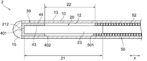
- FIG. 9 is a sectional view (partial side view) of a light irradiation medical device according to a second embodiment of the present invention.
- 10 is a cross-sectional view (partial side view) enlarging the distal side of the light irradiation medical device shown in FIG.
- FIG. 11 is an end view of the photoirradiation medical device shown in FIG. 10 taken along line XI-XI.
- 12 is a cut end view of the cylindrical member shown in FIG. 10.
- FIG. 13 to 15 are sectional views (partial side views) showing modifications of the light irradiation medical device shown in FIG.
- FIG. 16 is an enlarged cross-sectional view of the distal side of the optical fiber shown in FIG. 17 and 18 are sectional views showing modifications of the optical fiber shown in FIG.
- the light irradiation medical device 2 has a shaft 10 , an optical fiber 20 , a tubular member 39 , a second coil member 50 and a handle 60 .
- the light irradiation medical device may be simply referred to as the device.
- the shaft 10 is omitted from FIGS.
- the distal side of the device 2 refers to the side to be treated that is the distal end side of the shaft 10 in the longitudinal direction x.
- the proximal side of the device 2 refers to the proximal end side of the shaft 10 in the longitudinal direction x and the user's hand side.
- the proximal side may be called the proximal portion
- the distal side may be called the distal portion.
- the inner side refers to the direction toward the central axis c extending in the longitudinal direction x of the shaft 10
- the outer side refers to the radial direction opposite to the inner side.
- the device 2 has a shaft 10 having distal and proximal ends in the longitudinal direction x and having a lumen 11 extending in the longitudinal direction x.
- Shaft 10 has a tubular shape for arranging optical fiber 20 , tubular member 39 and second coil member 50 in lumen 11 thereof.
- a distal tip 15 may be attached to the distal end of the shaft 10 as shown in FIG.
- a handle 60 is connected to the proximal portion of the shaft 10 as shown in FIG.
- the handle 60 has a hollow portion 61 extending in the longitudinal direction x.
- the shaft 10 , the optical fiber 20 and the second coil member 50 are inserted through the hollow portion 61 .
- the device 2 has an optical fiber 20 arranged in the lumen 11 of the shaft 10 .
- the optical fiber 20 has a light diffusing portion 21 extending in the longitudinal direction x in a predetermined section of its distal portion and emitting light outward in the radial direction of the shaft 10 .
- the light diffusing portion 21 is arranged to extend in the longitudinal direction x and the circumferential direction p of the shaft 10 .
- the light diffusing portion 21 has an outer peripheral surface 23 .
- An outer peripheral surface 23 of the light diffusion portion 21 faces the inner peripheral surface 12 side of the shaft 10 .
- the proximal end of optical fiber 20 extends proximally from handle 60 .
- the proximal end of optical fiber 20 is connected to a light source such as a semiconductor laser.
- the device 2 is inserted through the endoscope to the position where the target tissue is in the body cavity. At this time, the target tissue is positioned radially outward of the outer peripheral surface 13 of the shaft 10 .
- the light emitted from the light diffusing portion 21 passes through at least a portion of the shaft 10 that overlaps the light diffusing portion 21 , so that the light reaches the target tissue around the device 2 .
- the light diffusing portion 21 From the light diffusing portion 21 , it is sufficient that light is emitted at least outward in the radial direction of the shaft 10 , and from the light diffusing portion 21 , the radial direction of the shaft 10 extends over the entire circumferential direction p of the shaft 10 . It is preferable that the light is emitted outward. Light may be emitted further from the light diffusing portion 21 toward the distal direction of the shaft 10, that is, toward the front. However, it is preferable that the device 2 does not include a device that emits light only in the distal direction of the shaft 10 from the light diffusing portion 21 .
- the device 2 is arranged proximal to the cylindrical member 39 of the lumen 11 of the shaft 10, and the wire 52 is helically wound around the optical fiber 20. It has a second coil member 50 . The entire second coil member 50 is arranged in the lumen 11 of the shaft 10 in the longitudinal direction x.
- a proximal portion of the second coil member 50 is fixed to the handle 60 .
- the second coil member 50 may be directly fixed to the handle 60, or may be indirectly fixed via another member.
- the method of fixing the second coil member 50 and the handle 60 is not particularly limited, but examples include welding, welding, crimping such as caulking, bonding with an adhesive, engagement, connection, binding, ligature, and other physical fixing methods. methods, or combinations thereof.
- FIG. 9 shows an example in which the outer peripheral surface of the proximal portion of the second coil member 50 is fixed to the inner peripheral surface 12 of the shaft 10 and the outer peripheral surface 13 of the shaft is fixed to the handle 60 .
- the proximal end of the second coil member 50 is preferably positioned distally relative to the proximal end of the handle 60 and may be positioned distally relative to the distal end of the handle 60 . Also, as shown in FIG. 9, the proximal end of the second coil member 50 is located distal to the proximal end of the handle 60 and proximal to the handle 60 relative to the distal end. may
- the device 2 is arranged in the lumen 11 of the shaft 10 and has a tubular member 39 covering part of the distal portion of the optical fiber 21 . As shown in FIGS. 9 and 10, part of the light diffusing section 21 is covered with a cylindrical member 39. As shown in FIGS. In this specification, a portion through which light is emitted at least radially outward when the cylindrical member 39 is removed from the optical fiber 20 is referred to as a light diffusion portion 21 . In a state where the cylindrical member 39 partially covers the light diffusing section 21, at least one of the distal end and the proximal end of the light diffusing section 21 may be hidden by the cylindrical member 39 and cannot be visually recognized. It may be difficult to know the location of the distal and proximal ends of 21 .
- the positions of the distal end and the proximal end of the light diffusing portion 21 are specified with the cylindrical member 39 removed from the optical fiber 20 . If part of the light diffusing portion 21 is also covered with the second coil member 50, when the cylindrical member 39 and the second coil member 50 are removed from the optical fiber 20, the light is emitted at least radially outward. The emitted part is called a light diffusion part 21 .
- an exposed portion 22 a portion of the light diffusing portion 21 that is not covered with the cylindrical member 39 and is exposed to the shaft 10 side is called an exposed portion 22 .
- the light diffusing portion 21 may be arranged only in a part of the shaft 10 in the circumferential direction p, but as shown in FIG. preferably. Since a wide range in the circumferential direction p can be irradiated with light at once, the efficiency of the procedure can be improved.
- the optical fiber 20 has a core 25 extending in the longitudinal direction x, and the optical fiber 20 has a first clad 26 disposed around the core 25. It has one section 31 .
- the first section 31 the light is likely to be totally reflected at the boundary between the core 25 and the first clad 26. Therefore, in the first section 31, the light is confined within the core 25 and propagates to the distal side of the optical fiber 20. .
- one core 25 is arranged in one first clad 26 in the first section 31 .
- the optical fiber can be rephrased as a single-core optical fiber.
- the first clad 26 may be positioned radially outwardly of the optical fiber 20 in the first section 31 . That is, the first section 31 does not need to be provided with other members such as a covering material.
- the first section 31 of the optical fiber 20 may be provided with a coating material around the outer periphery of the first clad 26 . It is possible to protect the outside of the first section 31 , and it is also possible to suppress light leakage and emission to the outside in the first section 31 .
- the coating material may be a coating layer arranged on the outer peripheral surface of the first clad 26 or a sheath enclosing the first clad 26 .
- the covering material can be made of a resin such as an ultraviolet curable resin.
- the optical fiber 20 has a second clad 27 arranged on the outer periphery of the core 25 in the light diffusion portion 21 and having a larger surface roughness of the outer peripheral surface than the first clad 26 . It has a distally located second section 32 .
- the clad surface roughness larger in the second section 32 than in the first section 31
- part of the light is confined within the core 25 and propagated to the distal side of the optical fiber 20, and the remaining light is transmitted to the second section 31. It leaks out from the clad 27 and is injected radially outward.
- the first section 31 does not emit light radially outward, or that the amount of light leakage is smaller than that of the second section 32 .
- one core 25 is preferably arranged in one second clad 27 .
- the first section 31 and the second section 32 may consist of one optical fiber.
- the first clad 26 of the first section 31 and the second clad 27 of the second section 32 may be integrally formed.
- the optical fiber 20 may be formed by joining the optical fiber for the first section 31 and the optical fiber for the second section 32 in the longitudinal axis direction x.
- the first clad 26 of the first section 31 and the second clad 27 of the second section 32 may be separately formed and then joined together.
- the second clad 27 is located on the outermost side of the optical fiber 20 in the radial direction. That is, in the second section 32, it is preferable that no member (for example, a covering material) other than the core 25 and the second clad 27 is arranged. With this configuration, light can be emitted outward in the radial direction of the shaft 10 from the second section 32 .
- the surface roughness of the outer peripheral surface of the second clad 27 in the second section 32 is greater than the surface roughness of the outer peripheral surface of the first clad 26 in the first section 31 .
- the surface roughness is the arithmetic mean roughness Ra between the reference lengths of the roughness curve in the longitudinal axis direction of the outer peripheral surface of the optical fiber 20 .
- the reference length may be set according to the magnification of the laser microscope used, and is, for example, 200 ⁇ m.
- the above arithmetic mean roughness Ra corresponds to the arithmetic mean roughness Ra specified in JIS B 0601 (2001) and is measured according to JIS B 0633 (2001).
- a measuring machine specified in JIS B 0651 (2001) for example, a laser microscope VK-X3000 manufactured by Keyence Corporation is used.
- the average value of the surface roughness of the outer peripheral surface of the second clad 27 in the second section 32 is preferably larger than the average value of the surface roughness of the outer peripheral surface of the first clad 26 in the first section 31 .
- the average value of the surface roughness is the average value of the surface roughness values of 10 or more measurement points set so as to be aligned in the longitudinal axis direction x in the section to be measured (for example, the first section 31). .
- the surface roughness of the outer peripheral surface of the second clad 27 in the proximal portion 324 is The average value is preferably smaller than the average surface roughness of the outer peripheral surface of the second clad 27 in the distal portion 323 .
- the proximal portion 324 enhances the effect of confining light within the core 25 more than the distal portion 323, while the distal portion 323 facilitates the radially outward emission of light from the second clad 27. Therefore, the emission intensity distribution of the second section 32 is easily uniformed in the longitudinal direction x.
- the second section 32 is preferably shorter than the first section 31 in the longitudinal axis direction x. It becomes easier to form the light diffusing portion 21, and the flexibility of the distal end portion of the optical fiber 20 can also be increased.
- the length of the second section 32 in the longitudinal direction x can be set to 1/20 or less, 1/25 or less, or 1/30 or less of the length of the first section 31 .
- the length of the second section 32 in the longitudinal axis direction x may be set to 1/50 or more, 1/45 or more, or 1/30 or more of the length of the first section 31. good.
- the average thickness of the second clad 27 in the second section 32 is preferably smaller than the average thickness of the first clad 26 in the first section 31.
- the clad thickness can be measured using a laser microscope VK-X3000 manufactured by Keyence Corporation.
- the optical fiber 20 when the optical fiber 20 has the first section 31, the optical fiber 20 has no cladding in the light diffusing portion 21 and is located distal to the first section 31. You may have the 3rd area 33 which is carrying out. Since there is no clad in the third section 33, the light from the core 25 is emitted radially outward.
- no clad exists in at least a part of the core 25 in the circumferential direction, and more preferably, no clad exists in the entire circumferential direction of the core 25.
- the core 25 is positioned radially outermost in the optical fiber 20.
- the outer diameter of the core 25 in the third section 33 may be a constant value, or the outer diameter of the core 25 may be a different value depending on the position in the longitudinal direction x.
- the distal end of the third section 33 is preferably at the same position as the distal end of the core 25 in the longitudinal direction x. It becomes easier to form the third section 33, and the flexibility at the distal end of the optical fiber 20 can also be increased.
- the surface roughness of the outer peripheral surface of the core 25 in the third section 33 is preferably larger than the surface roughness of the outer peripheral surface of the first clad 26 in the first section 31 . Light is likely to be confined within the core 25 in the first section 31 , and light is likely to be emitted radially outward from the core 25 in the third section 33 .
- At least one of the second section 32 and the third section 33 is preferably arranged in the light diffusion section 21, and both the second section 32 and the third section 33 may be arranged.
- the light diffusing portion 21 has a second section 32 and a third section 33 arranged in order from the proximal side to the distal side. With this configuration, the light emission intensity distribution of the light diffusing portion 21 can be easily uniformed in the longitudinal direction x.
- the first section 31, the second section 32, and the third section 33 are adjacent to each other in the longitudinal direction x. They are adjacent, and preferably the second section 32 and the third section 33 are adjacent.
- the third section 33 is shorter than the second section 32 in the longitudinal axis direction x as shown in FIG. With this configuration, it becomes easier to uniform the emission intensity distribution of the entire exposed portion 22 in the longitudinal direction x. A mode in which the second section 32 is shorter than the third section 33 in the longitudinal direction x is also allowed.
- the length of the third section 33 in the longitudinal direction x is preferably 20% or less of the total length of the second section 32 and the third section 33, and is preferably 18% or less. More preferably, the size is 15% or less. In addition, the length of the third section 33 in the longitudinal direction x may be 5% or more, 8% or more, or 10% or more of the total length of the second section 32 and the third section 33. . This configuration makes it easier to uniformize the emission intensity distribution of the exposed portion 22 in the longitudinal direction x.
- the average value of the surface roughness of the outer peripheral surface of the second clad 27 in the second section 32 is preferably smaller than the average value of the surface roughness of the outer peripheral surface of the core 25 in the third section 33 . This configuration makes it easier to uniformize the emission intensity distribution in the longitudinal axis direction x in each of the second section 32 and the third section 33 .
- the optical fiber 20 may have only the second section 32 in the light diffusing portion 21 . That is, the optical fiber 20 does not have to have the third section 33 in the light diffusing portion 21 . Even with the configuration having only the second section 32, the emission intensity distribution of the exposed portion 22 in the longitudinal axis direction x can be made uniform. Since the core 25 is not exposed, it also has the effect of preventing damage to the optical fiber 20 due to bending of the device 2 during the procedure.
- the distal end of the second section 32 is preferably at the same position as the distal end of the core 25 in the longitudinal direction x. .
- the optical fiber 20 may have only the third section 33 in the light diffusing portion 21 . That is, the optical fiber 20 does not have to have the second section 32 in the light diffusing portion 21 . Even with the configuration having only the third section 33, the emission intensity distribution of the exposed portion 22 in the longitudinal axis direction x can be made uniform.
- the second section 32 and the third section 33 can be formed by removing the clad by etching or polishing.
- the outer peripheral surface of the second clad 27 and the outer peripheral surface of the core 25 of the third section 33 may be uneven.
- the unevenness can be formed by mechanically or chemically roughening the surface of the core 25 of the second clad 27 or the third section 33 . Examples of methods for roughening the surface include etching, blasting, a method using a scribe, a wire brush, or sandpaper.
- the cylindrical member 39 is arranged in the lumen 11 of the shaft 10 and partially covers the distal portion of the optical fiber 20. As shown in FIG. Specifically, the cylindrical member 39 partially covers the light diffusion section 21 . According to the device 2 , the light emitted from the light diffusing portion 21 is reflected by the inner surface of the cylindrical member 39 in the portion of the light diffusing portion 21 covered with the cylindrical member 39 , so that the reflected light is reflected on the light diffusing portion 21 . It becomes easy to diffuse in various directions from the exposed portion 22 , which is the portion not covered with the cylindrical member 39 . As a result, the emission intensity distribution of the exposed portion 22 is more likely to be uniform in the circumferential direction p of the shaft 10 .
- FIG. 10 shows how the light traveling from the proximal side toward the distal side is directly emitted from the exposed portion 22, and how the light is emitted from the exposed portion 22 after being reflected by the cylindrical member 39.
- An example is indicated by a thick arrow.
- the tubular member 39 covers only a part of the light diffusing section 21 and does not cover the entire light diffusing section 21 . That is, the exposed portion 22 is always formed in the light diffusion portion 21 .
- the tubular member 39 is formed to extend in the longitudinal direction x of the shaft 10 .
- a direction of the tubular member 39 that is parallel to the longitudinal axis direction x of the shaft 10 is referred to as an axial direction of the tubular member 39 .
- the tubular member 39 has an inner peripheral surface 43 and an outer peripheral surface 44 .
- the inner peripheral surface 43 extends in the circumferential direction p of the shaft 10 and faces the outer peripheral surface 23 side of the optical fiber 20 .
- the outer peripheral surface 44 extends in the circumferential direction p of the shaft 10 and faces the inner peripheral surface 12 side of the shaft 10 . It is preferable that the light emitted from the light diffusing portion 21 is reflected at least by the inner peripheral surface 43 of the tubular member 39 .
- the tubular member 39 may have a shape in which the distal end 401 side is closed and the proximal end 402 side is open.
- the tubular member 39 has an outer end face 45 on the distal end 401 side and an inner end face 46 on the distal end 401 side.
- This shape can also be rephrased as a bottomed tubular shape in which the closed portion on the distal end 401 side is the tubular bottom.
- the outer end surface 45 on the distal end 401 side is a visible surface when the tubular member 39 is viewed from the distal side toward the proximal side.
- the inner end surface 46 on the distal end 401 side corresponds to the inner bottom surface of the bottomed cylindrical shape.
- the cylindrical member 39 may have a cylindrical shape with openings on the distal end 401 side and the proximal end 402 side.
- the inner peripheral surface 43 may be composed of only the curved surface portion, may be composed of only the flat surface portion, or may be composed of a combination of the curved surface portion and the flat surface portion.
- the inner peripheral surface 43 preferably has a curved surface portion in order to facilitate diffusion of the light reflected by the inner peripheral surface 43 in multiple directions.
- the inner end surface 46 may be composed of only the flat surface portion, may be composed of only the curved surface portion, or may be composed of a combination of the curved surface portion and the flat surface portion.
- the cylindrical member 39 preferably has one lumen.
- the shape of the cylindrical member 39 is not particularly limited, but may be a cylindrical shape, an oblong cylindrical shape, or a polygonal cylindrical shape.
- the axial length of the tubular member 39 may be larger or smaller than the maximum outer diameter of the tubular member 39 .
- the tubular member 39 preferably has a first coil portion 41 in which a wire 42 is helically wound around the light diffusion portion 21. .
- the light emitted from the light diffusing portion 21 is reflected by the inner surface of the coil portion 41 . diffuse in various directions from the exposed portion 22 that is not covered with .
- the configuration of the first coil portion 41 will be described later.
- the cylindrical member 39 may not have a coil shape around which the wire rod 42 is wound, and may be a cylindrical body such as a resin tube or a metal pipe as shown in FIG.
- the light emitted from the light diffusing portion 21 does not pass through the tubular member 39 outward in the radial direction of the shaft 10 .
- the distal end 401 of the tubular member 39 is preferably located at the same position as the distal end of the light diffusing section 21 or further distal than the distal end of the light diffusing section 21. .
- the light diffusing portion 21 has a longitudinal axis direction, and the longitudinal axis direction of the light diffusing portion 21 is parallel to the longitudinal axis direction x of the shaft 10 .
- the proximal end 402 of the tubular member 39 is preferably positioned distally of the midpoint 211 of the light diffusing portion 21 in the longitudinal direction. Since the exposed portion 22 can be formed long in the longitudinal axis direction of the light diffusing portion 21, a wide range in the longitudinal axis direction can be irradiated with light at once.
- the cylindrical member 39 is preferably arranged at a position including the distal end of the light diffusion section 21 . It is preferable that the cylindrical member 39 is not located on the proximal side of the midpoint 211 of the light diffusing portion 21 in the longitudinal direction.
- the entire cylindrical member 39 is arranged in the lumen 11 of the shaft 10 in the longitudinal direction x.
- the length of the cylindrical member 39 can be set to 1/2 or less, 1/3 or less, or 1/4 or less of the length of the exposed portion 22.
- the length of the cylindrical member 39 in the longitudinal axis direction x may be set to 1/20 or more, 1/18 or more, or 1/15 or more of the length of the exposed portion 22 .
- the outer diameter of the tubular member 39 may be constant in the longitudinal axis direction x of the shaft 10, or the outer diameter of the tubular member 39 may vary depending on the position in the longitudinal axis direction x. For example, when the tubular member 39 is divided into a distal portion and a proximal portion in the longitudinal direction x, the average outer diameter of the distal portion of the tubular member 39 is equal to the average outer diameter of the proximal portion of the tubular member 39. may be greater than
- the tubular member 39 is preferably made of a material having a higher reflectance than the shaft 10 . This configuration makes it easier for the reflected light to diffuse on the inner surface of the tubular member 39 .
- the reflectance refers to the reflectance of light emitted from the light diffusing portion 21, and the unit is %.
- the reflectance can be measured using a reflectance measurement system OP-RF-VIS-GT50 manufactured by Ocean Photonics.
- the cylindrical member 39 is preferably made of metal, for example, radiopaque metals such as gold, silver, platinum, palladium, tungsten, tantalum, iridium and alloys thereof, stainless steel, Ni—Ti alloys. and other superelastic alloys.
- radiopaque metals such as gold, silver, platinum, palladium, tungsten, tantalum, iridium and alloys thereof, stainless steel, Ni—Ti alloys. and other superelastic alloys.
- the tubular member 39 may have a tubular member main body and a reflective layer arranged on the inner surface of the tubular member main body.
- the light from the light diffusing portion 21 can be reflected by the reflective layer regardless of the material of the cylindrical member main body.
- a coil body or a resin tube around which a resin wire is wound may be used as the tubular member main body.
- the reflective layer may be provided by applying a coating agent containing a reflective material to the inner surface of the cylindrical member body, and the reflective material is applied to the inner surface of the cylindrical member body by a method such as vapor deposition, sputtering, electroplating, or chemical plating. It may be arranged by adhering.
- the reflective layer may be a metal thin film.
- Reflective materials include, for example, aluminum, gold, silver, copper, tin, titanium dioxide, tantalum pentoxide, aluminum oxide, silicon dioxide, magnesium fluoride, or combinations thereof. If the tubular member 39 has a reflective layer, any of the materials listed as the constituent materials of the shaft 10 can be used for the tubular member main body.
- the tubular member 39 with the distal end 401 side closed as shown in FIG. 12 can be obtained.
- a tubular coil having one lumen and a metallic member separate from the tubular coil are prepared, and the metallic member is heated and welded so as to close the opening on the distal side of the tubular coil. It is also possible to obtain a tubular member 39 closed on the proximal end 401 side.
- Concavities and convexities may be arranged on the inner peripheral surface 43 of the tubular member 39 .
- the concave-convex structure of the inner peripheral surface 43 of the cylindrical member 39 can be formed by etching, blasting, roughening the inner peripheral surface 43 of the cylindrical member 39 with a scribe, wire brush, or sandpaper.
- the unevenness may be arranged only on a part of the tubular member 39, or the unevenness may be arranged on the entirety of the tubular member 39. Moreover, in the circumferential direction of the shaft 10 , the unevenness may be provided only on a part of the tubular member 39 , or the unevenness may be provided on the entirety of the tubular member 39 .
- a reflector 17 that reflects the light from the light diffusing portion 21 is arranged on the distal end 401 side of the tubular member 39 .
- the reflector 17 is, for example, a mirror arranged so that the reflecting surface faces the proximal side. With this configuration, light can be reflected not only by the inner peripheral surface of the cylindrical member 39 but also by the reflector 17, so that the reflected light can be easily diffused in various directions.
- the reflector 17 is arranged on the distal side of the cylindrical member 39. As shown in FIG. although not shown, the reflector 17 may be arranged on the most distal side of the lumen of the tubular member 39 . When the distal end 401 side of the tubular member 39 is closed, the inner end face 46 of the tubular member 39 and the distal end face of the reflector 17 may be in contact with each other.
- the tubular member 39 preferably covers a portion of the second section 32 and a portion of the distal portion of the second section 32 as shown in FIG. is more preferably covered.
- the light emitted radially outward from the light diffusing portion 21 can be reflected by the portion of the second section 32 covered with the cylindrical member 39 .
- the cylindrical member 39 does not cover the entire second section 32 .
- the tubular member 39 covers at least part of the third section 33.
- the light emitted radially outward from the light diffusing portion 21 can be reflected by the portion of the third section 33 covered with the cylindrical member 39 .
- the tubular member 39 may cover only a portion of the third section 33 as shown in FIG. In that case, the tubular member 39 preferably covers a portion of the distal portion of the third section 33 .
- the cylindrical member 39 may cover the entire third section 33 as shown in FIG. 17 .
- the proximal end 402 of the tubular member 39 may be positioned further distally than the distal end of the second section 32 .
- the cylindrical member 39 may be arranged only in the third section 33 and not arranged in the second section 32 .
- the proximal end 402 of the tubular member 39 may be positioned closer to the proximal side than the distal end of the second section 32 .
- the cylindrical member 39 may be arranged in part of the second section 32 and at least part of the third section 33 .
- a wire rod 42 forming the first coil portion 41 has a tip end and a base end in the longitudinal direction.
- the wire rod 42 that constitutes the first coil portion 41 may be composed of a single linear member from the distal end to the base end, and the wire rods 42 that constitute the first coil portion 41 are connected to each other in the longitudinal direction. It may be composed of a plurality of linear members.
- the shape of the cross section perpendicular to the longitudinal axis direction of the wire 42 forming the first coil portion 41 may be circular, oval, polygonal, or a combination thereof.
- the shape of the cross section perpendicular to the longitudinal axis direction of the wire 42 forming the first coil portion 41 is preferably circular or oval.
- the inner peripheral surface 43 of the cylindrical member 39 has a plurality of protrusions 491 extending in the longitudinal axis direction x. arranged side by side.
- the recess 492 is arranged between the two protrusions 491 . Reflected light is easily diffused in multiple directions by the protrusions 491 and the recesses 492 of the inner peripheral surface 43 .
- the wire diameter (thickness) of the wire 42 forming the first coil portion 41 and the number of turns of the wire 42 forming the first coil portion 41 are not particularly limited. 9 and 10 show an example in which the first coil portion 41 is wound in a single layer, it may be wound in multiple layers, or may be wound in a single layer and in multiple layers.
- the axial length of the first coil portion 41 may be larger or smaller than the maximum outer diameter of the first coil portion 41 .
- the pitch P1 of the first coil portion 41 is not particularly limited, and may be constant in the axial direction or may vary depending on the position in the axial direction.
- the pitch P1 is the distance between the central axes of two adjacent wires 42 forming the first coil portion 41 in the axial direction, as shown in FIG.
- the first coil portion 41 gaps may be formed between the wire rods 42 adjacent in the axial direction, but the gaps between the adjacent wire rods 42 are preferably not too large. This is because if too much light leaks through the gaps between the adjacent wires 42, the light emission intensity at the exposed portion 22 may be reduced. Therefore, it is preferable that the first coil portion 41 has a first pitch portion 48 having a pitch of twice or less than the wire diameter of the wire rod 42 .
- the first coil portion 41 may have the same pitch as the wire diameter of the wire rod 42 .
- Such coils are commonly referred to as tight wound coils.
- a tightly wound coil is preferable because there is no gap between two adjacent wire rods 42 and light is less likely to leak from the first coil portion 41 .
- the first pitch portion 48 the cylindrical member 39 may have a pitch smaller than the wire diameter of the wire 42 .
- the first coil portion 41 may have a pitch of 1.1 times or more the wire diameter of the wire 42, or may have a pitch of 1.2 times or more. In the first pitch portion 48, the first coil portion 41 may have a pitch of 1.9 times or less the wire diameter of the wire rod 42, or may have a pitch of 1.8 times or less. . By setting the pitch in this way, it is possible to suppress leakage of light from the first coil portion 41, which is preferable.
- the first pitch portion 48 may constitute only a part of the first coil portion 41 in the axial direction. Further, as shown in FIG. 9 , the first pitch portion 48 may constitute the entire axial direction of the first coil portion 41 .
- the first coil portion 41 constitutes only a part of the cylindrical member 39 in the axial direction.
- the trunk portion is the first coil portion 41. is preferred.
- the second coil member 50 is arranged proximal to the cylindrical member 39 of the lumen 11 of the shaft 10, and the wire 52 is helically wound around the optical fiber 20. is wound on.
- the entire second coil member 50 is arranged in the lumen 11 of the shaft 10 in the longitudinal direction x.
- the second coil member 50 is formed to extend in the longitudinal direction x of the shaft 10 .
- a direction of the second coil member 50 that is parallel to the longitudinal axis direction x of the shaft 10 is referred to as an axial direction of the second coil member 50 .
- the second coil member 50 has an inner peripheral surface 53 and an outer peripheral surface 54 .
- the inner peripheral surface 53 extends in the circumferential direction p of the shaft 10 and faces the outer peripheral surface 23 side of the optical fiber 20 .
- the outer peripheral surface 54 extends in the circumferential direction p of the shaft 10 and faces the inner peripheral surface 12 side of the shaft 10 .
- the second coil member 50 preferably has a shape in which the distal end 501 side and the proximal end 502 side are respectively opened.
- the second coil member 50 is entirely disposed in the lumen 11 of the shaft 10 in the longitudinal direction x as shown in FIG. located distal to the
- the second coil member 50 covers part of the light diffusing section 21 .
- the length of the exposed portion 22 in the longitudinal direction x can be fixed.
- the incident light from the light source should be totally reflected due to the presence of the cladding of the optical fiber 20 and propagated to the distal side. Light may leak out.
- the second coil member 50 since the second coil member 50 partially covers the light diffusing portion 21 , the light emitted from the light diffusing portion 21 can also be reflected on the inner surface of the second coil member 50 . can be done. As a result, leakage of light from the proximal side of the light diffusing portion 21 can be suppressed, and light from the light source can be efficiently guided to the light diffusing portion 21 .
- part of the light diffusing section 21 is not covered with the cylindrical member 39 and the second coil member 50. That is, it is preferable that the proximal end 402 of the cylindrical member 39 and the distal end 501 of the second coil member 50 are arranged apart in the longitudinal direction x. By arranging the tubular member 39 and the second coil member 50 in this manner, the exposed portion 22 is formed, and thus light can be emitted radially outward from the exposed portion 22 .
- the light emitted from the light diffusing portion 21 is preferably reflected by the inner peripheral surface 53 of the portion of the second coil member 50 covering the light diffusing portion 21 . Reflected light is easily diffused in various directions from the exposed portion 22 of the light diffusing portion 21 that is not covered with the second coil member 50 .
- the inner peripheral surface 53 of the second coil member 50 may be composed only of the curved surface portion, may be composed of only the flat surface portion, or may be composed of a combination of the curved surface portion and the flat surface portion. In order to facilitate diffusion of the light reflected by the inner peripheral surface 53 in multiple directions, the inner peripheral surface 53 preferably has a curved surface portion.
- the light emitted from the light diffusing portion 21 does not pass through the second coil member 50 outward in the radial direction of the shaft 10 .
- the second coil member 50 is longer than the tubular member 39 in the longitudinal axis direction x. Since the second coil member 50 can cover a wide area in the longitudinal direction of the optical fiber, the torque transmissibility can be enhanced.
- a portion of the second coil member 50 that covers the light diffusion portion 21 is preferably made of a material having a higher reflectance than the shaft 10 . This configuration facilitates diffusion of the reflected light on the inner surface of the second coil member 50 .
- the reflectance refers to the reflectance of light emitted from the light diffusing portion 21, and the unit is %.
- the reflectance of the second coil member 50 can be measured by the same method as for the tubular member 39 .
- the second coil member 50 is preferably made of metal, such as gold, silver, platinum, palladium, tungsten, tantalum, iridium, and alloys thereof.
- a superelastic alloy such as a Ti alloy may also be used.
- a part of the second coil member 50 may be made of resin.
- the second coil member 50 may have a second coil member main body and a reflective layer arranged on the inner surface of the second coil member main body.
- the light from the light diffusing section 21 can be reflected by the reflective layer regardless of the material of the second coil member main body.
- a coil body or a resin tube around which a resin wire is wound may be the second coil member main body.
- the reflective layer may be provided by applying a coating agent containing a reflective material to the inner surface of the second coil member main body, and the reflective material is applied to the second coil member by a method such as vapor deposition, sputtering, electroplating, or chemical plating. It may be arranged by adhering to the inner surface of the body.
- the reflective layer may be a metal thin film.
- the reflective material those mentioned in the description of the cylindrical member 39 can be used.
- the second coil member 50 has a reflective layer, at least one of the materials listed as the constituent materials of the shaft 10 can be used for the second coil member main body.
- a wire rod 52 that constitutes the second coil member 50 has a distal end and a proximal end in its longitudinal direction.
- the wire 52 may be composed of a single linear member from the distal end to the proximal end, or the wire 52 may be composed of a plurality of linear members connected to each other in the longitudinal direction thereof.
- the cross-sectional shape of the wire 52 perpendicular to the longitudinal axis direction may be circular, oval, polygonal, or a combination thereof.
- the oval shape includes an elliptical shape, an egg shape, and a rounded rectangular shape.
- the shape of the cross section perpendicular to the longitudinal axis direction of the wire rod 52 is preferably circular or oval.
- a plurality of protrusions are formed in the longitudinal axis direction x on the inner peripheral surface 53 of the second coil member 50 in the same manner as the tubular member 39 . are arranged so as to line up, and a concave portion is arranged between two convex portions. Reflected light is easily diffused in multiple directions on the proximal side of the light diffusing portion 21 due to the protrusions and recesses of the inner peripheral surface 53 .
- the wire diameter (thickness) of the wire 52 constituting the second coil member 50 and the number of turns of the wire 52 are not particularly limited.
- the axial length of the second coil member 50 may be larger or smaller than the maximum outer diameter of the second coil member 50 .
- the pitch P2 of the second coil member 50 is not particularly limited, and may be constant in the axial direction or may vary depending on the position in the axial direction.
- the pitch P2 is the distance between the central axes of two adjacent wires 52 forming the second coil member 50 in the axial direction, as shown in FIG.
- a gap may be formed between the wire rods 52 adjacent in the axial direction.
- the second coil member 50 preferably has a second pitch portion 58 having a pitch of twice or less than the wire diameter of the wire rod 52 .
- the second coil member 50 may have the same pitch as the wire diameter of the wire 52 . That is, there may be no gap between two adjacent wires 52 .
- the second pitch portion At 58 the second coil member 50 may have a pitch smaller than the wire diameter of the wire 52 .
- the second coil member 50 may have a pitch of 1.1 times or more the wire diameter of the wire 52, or may have a pitch of 1.2 times or more. In the second pitch portion 58, the second coil member 50 may have a pitch of 1.9 times or less the wire diameter of the wire 52, or may have a pitch of 1.8 times or less. .
- the second pitch portion 58 may constitute only a part of the second coil member 50 in the axial direction. Further, as shown in FIG. 9, the second pitch portion 58 may constitute the entire second coil member 50 in the axial direction.
- the second coil member 50 may be a single-layer wound coil, a multi-layer wound coil, or a combination thereof.
- FIG. 9 shows an example in which the second coil member 50 is a single-layer wound coil.
- the first coil portion 41 of the tubular member 39 is wound in a single layer, and the second coil member 50 has a second coil portion 51a that is wound in multiple layers. Due to the single-layer winding of the first coil portion 41 , reflected light can be easily diffused in multiple directions on the inner peripheral surface 43 of the cylindrical member 39 . In addition, the second coil portion 51a that is wound in multiple layers facilitates the transmission of torque on the proximal side to the distal side, so that the operability of the device 2 can be enhanced.
- the first coil part 41 is preferably made of a radiopaque material. Since the first coil portion 41 can be used as a radiopaque marker, the operator can easily grasp the position of the light diffusion portion 21 on the distal side. Since the second coil portion 51a is preferably arranged to extend over a wide range in the axial direction, it is rather difficult to grasp the position of the light diffusing portion 21 if it is made of a radiopaque material. For this reason, it is preferable that the second coil portion 51a is made of a material that transmits radiation more easily than the first coil portion 41 does.
- the first coil portion 41 is preferably made of, for example, gold, silver, platinum, palladium, tungsten, tantalum, iridium, or alloys thereof.
- the second coil portion 51a is preferably made of metal such as stainless steel, carbon steel, nickel-titanium alloy, or the like.
- the second coil member 50 includes a second coil portion 51a that is wound in multiple layers, and a third coil portion 51b that is positioned distally of the second coil portion 51a and is wound in a single layer. have.
- the wire 52a is spirally wound around the optical fiber 20 in three layers.
- the wire rod 52b is spirally wound around the optical fiber 20 in one layer.
- the second coil portion 51a is preferably longer than the third coil portion 51b in the longitudinal axis direction x.
- the multi-layer wound second coil portion 51a may be positioned further to the distal side than the single-layer wound third coil portion 51b.
- the third coil portion 51 b covers part of the light diffusion portion 21 and the second coil portion 51 a is located closer to the light diffusion portion 21 than the light diffusion portion 21 .
- the distal end of the third coil portion 51b is positioned further distal than the proximal end of the light diffusing portion 21, and the proximal end of the third coil portion 51b is closer to the light diffusing portion 21. It is preferably located more proximal than the proximal end. This configuration makes it easier for the third coil portion 51b to have both functions of reflecting light from the light diffusing portion 21 and transmitting torque satisfactorily.
- the third coil portion 51b is preferably made of a radiopaque material through which radiation is less likely to pass than the second coil portion 51a. As a result, the third coil portion 51b can be used as a radiopaque marker, making it easier for the operator to grasp the proximal position of the light diffusing portion 21 .
- the third coil portion 51b is preferably made of, for example, gold, silver, platinum, palladium, tungsten, tantalum, iridium, or alloys thereof.
- the third coil portion 51b may be made of the same material as the second coil portion 51a, but is preferably made of a different material.
- Each layer of the second coil portion 51a may be made of different materials, but preferably made of the same material.
- the third coil portion 51b may be made of a material different from that of the first coil portion 41, but is preferably made of the same material.
- the minimum inner diameter of the tubular member 39 may be smaller than the minimum inner diameter of the second coil member 50. Since the tubular member 39 is firmly fixed to the optical fiber 20, it is possible to prevent the tubular member 39 from falling off from the optical fiber 20, which is preferable. For example, by crimping the cylindrical member 39 and fixing it to the optical fiber 20, such a size relationship is obtained.
- the tubular member 39 is fixed to the light diffusing portion 21 . More preferably, the cylindrical member 39 is fixed to the outer peripheral surface 23 of the light diffusing portion 21 as shown in FIG. 10 . Further, as can be understood from FIGS. 10 and 12, it is more preferable that the inner peripheral surface 43 of the tubular member 39 is fixed to the outer peripheral surface 23 of the light diffusing portion 21 . Since the position of the proximal end 402 of the cylindrical member 39 is fixed so as not to shift with respect to the light diffusing portion 21 in the longitudinal axis direction x even when the device 2 is inserted into the body, the irradiation position can be stabilized. Note that even when the cylindrical member 39 is fixed to the outer peripheral surface 23 of the light diffusing portion 21 , it is preferable that the cylindrical member 39 also bends following the bending of the device 2 .
- the cylindrical member 39 When fixing the cylindrical member 39 to the light diffusing portion 21, the cylindrical member 39 is preferably in contact with the outer peripheral surface 23 of the light diffusing portion 21, and the inner peripheral surface 43 of the cylindrical member 39 is aligned with the light diffusing portion 21. More preferably, it is in contact with the outer peripheral surface 23 . This prevents an increase in the profile of the optical fiber 20 to which the cylindrical member 39 is attached and makes it easier for the cylindrical member 39 to reflect light.
- the light diffusing part 21 When the light diffusing part 21 is arranged at the distal end of the optical fiber 20, the light diffusing part 21 has a distal end surface 212 as shown in FIG. In that case, it is preferable that the distal end face 212 of the light diffusing portion 21 is not fixed to the tubular member 39 . By unfixing the distal end face 212 in this way, even when the device 2 passes through a bend in the body, the distal end 401 side of the tubular member 39 is not stretched and can easily follow the curve of the shaft 10 . As a result, the risk of breakage of the optical fiber 20 can be reduced, and the emission intensity distribution of the exposed portion 22 can be easily made uniform in the circumferential direction p of the shaft 10 .
- the distal end face 212 of the light diffusing portion 21 need only be fixed so as not to move with respect to the cylindrical member 39. As shown in FIG. It is permissible to have
- the distal end face 212 of the light diffusing portion 21 preferably has a planar shape perpendicular to the longitudinal axis direction of the optical fiber 20 as shown in FIG. It may have a planar shape, or may have a curved shape.
- the outer peripheral surface 44 of the tubular member 39 is in contact with the inner peripheral surface 12 of the shaft 10 .
- the position of the cylindrical member 39 relative to the shaft 10 is less likely to shift and the position of the exposed portion 22 is fixed, so that the irradiation position can be stabilized.
- the tubular member 39 may be inserted into the inner cavity 11 of the shaft 10 , and the outer peripheral surface 44 of the tubular member 39 may not be fixed to the inner peripheral surface 12 of the shaft 10 .
- the distal portion of the second coil member 50 is preferably not fixed to the optical fiber 20. With this configuration, even when the device 2 passes through a bend in the body, the distal portion of the second coil member 50 is not stretched and can easily follow the bending of the shaft 10 .
- the distal portion of the second coil member 50 need only be fixed so as not to move with respect to the optical fiber 20, and the distal portion of the second coil member 50 is in contact with the optical fiber 20 (for example, the second coil It is permissible for the inner peripheral surface of the distal portion of member 50 to be in contact with the outer peripheral surface of optical fiber 20). At least part of the inner peripheral surface of the distal portion of the second coil member 50 may be arranged apart from the outer peripheral surface of the optical fiber 20 .
- the second coil member 50 when the second coil member 50 partially covers the second section 32, the second coil member 50 is in contact with the outer peripheral surface of the second clad 27 of the second section 32. may although not shown, when the second coil member 50 covers at least a portion of the third section 33 , the second coil member 50 may be in contact with the outer peripheral surface of the core 25 of the third section 33 . As shown in FIG. 18 , when the second coil member 50 covers at least part of the third section 33 , the second coil member 50 does not have to be in contact with the outer peripheral surface of the core 25 of the third section 33 . .
- the outer peripheral surface 54 of the second coil member 50 is preferably in contact with the inner peripheral surface 12 of the shaft 10 .
- the position of the second coil member 50 relative to the shaft 10 is less likely to shift and the position of the exposed portion 22 is fixed, so that the irradiation position can be stabilized.
- the second coil member 50 need only be inserted into the lumen 11 of the shaft 10 , and the outer peripheral surface 54 of the second coil member 50 does not have to be fixed to the inner peripheral surface 12 of the shaft 10 .
- the outer peripheral surface 23 of the light diffusing portion 21 is preferably arranged apart from the inner peripheral surface 12 of the shaft 10 . More preferably, the outer peripheral surface 23 of the light diffusing portion 21 is arranged apart from the inner peripheral surface 12 of the shaft 10 in the exposed portion 22 . Further, it is more preferable that the outer peripheral surface 23 of the light diffusing portion 21 is separated from the inner peripheral surface 12 of the shaft 10 over the entire lengthwise direction x.
- the outer peripheral surface 23 of the light diffusion portion 21 be separated from the inner peripheral surface 12 of the shaft 10 over the entire circumferential direction p of the shaft 10 . Moreover, it is preferable that the distance between the outer peripheral surface 23 of the light diffusion portion 21 and the inner peripheral surface 12 of the shaft 10 in the radial direction of the shaft 10 be uniform at any position in the circumferential direction p of the shaft 10 . As a result, the emission intensity distribution of the exposed portion 22 can be easily uniformed in the circumferential direction p.
Landscapes
- Health & Medical Sciences (AREA)
- Biomedical Technology (AREA)
- Engineering & Computer Science (AREA)
- Life Sciences & Earth Sciences (AREA)
- Nuclear Medicine, Radiotherapy & Molecular Imaging (AREA)
- Physics & Mathematics (AREA)
- General Health & Medical Sciences (AREA)
- Veterinary Medicine (AREA)
- Public Health (AREA)
- Animal Behavior & Ethology (AREA)
- Radiology & Medical Imaging (AREA)
- Optics & Photonics (AREA)
- Surgery (AREA)
- Pathology (AREA)
- Otolaryngology (AREA)
- Molecular Biology (AREA)
- Medical Informatics (AREA)
- Heart & Thoracic Surgery (AREA)
- Electromagnetism (AREA)
- Light Guides In General And Applications Therefor (AREA)
Priority Applications (1)
| Application Number | Priority Date | Filing Date | Title |
|---|---|---|---|
| JP2023533454A JPWO2023281917A1 (https=) | 2021-07-07 | 2022-05-13 |
Applications Claiming Priority (4)
| Application Number | Priority Date | Filing Date | Title |
|---|---|---|---|
| JP2021-112715 | 2021-07-07 | ||
| JP2021-112714 | 2021-07-07 | ||
| JP2021112714 | 2021-07-07 | ||
| JP2021112715 | 2021-07-07 |
Publications (1)
| Publication Number | Publication Date |
|---|---|
| WO2023281917A1 true WO2023281917A1 (ja) | 2023-01-12 |
Family
ID=84800524
Family Applications (1)
| Application Number | Title | Priority Date | Filing Date |
|---|---|---|---|
| PCT/JP2022/020215 Ceased WO2023281917A1 (ja) | 2021-07-07 | 2022-05-13 | 光照射医療装置 |
Country Status (2)
| Country | Link |
|---|---|
| JP (1) | JPWO2023281917A1 (https=) |
| WO (1) | WO2023281917A1 (https=) |
Citations (4)
| Publication number | Priority date | Publication date | Assignee | Title |
|---|---|---|---|---|
| JP2015077168A (ja) * | 2013-10-15 | 2015-04-23 | ニプロ株式会社 | アブレーションデバイス |
| JP2019051023A (ja) * | 2017-09-14 | 2019-04-04 | 住友電気工業株式会社 | 医療ライトガイド |
| WO2021033465A1 (ja) * | 2019-08-20 | 2021-02-25 | 株式会社カネカ | 光照射医療装置 |
| JP2021090503A (ja) * | 2019-12-06 | 2021-06-17 | 朝日インテック株式会社 | 光照射デバイス |
-
2022
- 2022-05-13 WO PCT/JP2022/020215 patent/WO2023281917A1/ja not_active Ceased
- 2022-05-13 JP JP2023533454A patent/JPWO2023281917A1/ja active Pending
Patent Citations (4)
| Publication number | Priority date | Publication date | Assignee | Title |
|---|---|---|---|---|
| JP2015077168A (ja) * | 2013-10-15 | 2015-04-23 | ニプロ株式会社 | アブレーションデバイス |
| JP2019051023A (ja) * | 2017-09-14 | 2019-04-04 | 住友電気工業株式会社 | 医療ライトガイド |
| WO2021033465A1 (ja) * | 2019-08-20 | 2021-02-25 | 株式会社カネカ | 光照射医療装置 |
| JP2021090503A (ja) * | 2019-12-06 | 2021-06-17 | 朝日インテック株式会社 | 光照射デバイス |
Also Published As
| Publication number | Publication date |
|---|---|
| JPWO2023281917A1 (https=) | 2023-01-12 |
Similar Documents
| Publication | Publication Date | Title |
|---|---|---|
| JP7454571B2 (ja) | 光治療診断装置 | |
| CN114173691B (zh) | 光照射医疗装置 | |
| US12257447B2 (en) | Light irradiation device and light irradiation system | |
| WO2020071023A1 (ja) | 光照射医療装置 | |
| US11874455B2 (en) | Light irradiation device and light irradiation system | |
| WO2024184947A1 (ja) | 光照射デバイスおよび光照射システム | |
| JP2021090503A (ja) | 光照射デバイス | |
| US12496459B2 (en) | Light irradiation device and light irradiation system | |
| JP7389801B2 (ja) | 光治療診断装置およびその作動方法 | |
| WO2021019981A1 (ja) | カテーテル、及び、光照射システム | |
| WO2023047711A1 (ja) | 光照射医療装置 | |
| WO2023281917A1 (ja) | 光照射医療装置 | |
| JP7718934B2 (ja) | 光照射医療装置 | |
| JP7687889B2 (ja) | 光照射医療装置 | |
| WO2022118559A1 (ja) | 光照射医療装置 | |
| JP2023009439A (ja) | 光照射医療装置 | |
| WO2023281918A1 (ja) | 光照射医療装置 | |
| JP7773481B2 (ja) | 光照射医療装置 | |
| WO2023047709A1 (ja) | 光照射医療装置 | |
| JP2024136905A (ja) | 光照射医療装置 | |
| JP2024136907A (ja) | 光照射医療装置 | |
| JP2024136906A (ja) | 光照射医療装置 | |
| WO2023047710A1 (ja) | 光照射医療装置および光照射医療装置の製造方法 | |
| JP2024139234A (ja) | 光照射医療装置 | |
| JP7807328B2 (ja) | 光照射医療装置 |
Legal Events
| Date | Code | Title | Description |
|---|---|---|---|
| 121 | Ep: the epo has been informed by wipo that ep was designated in this application |
Ref document number: 22837338 Country of ref document: EP Kind code of ref document: A1 |
|
| WWE | Wipo information: entry into national phase |
Ref document number: 2023533454 Country of ref document: JP |
|
| NENP | Non-entry into the national phase |
Ref country code: DE |
|
| 122 | Ep: pct application non-entry in european phase |
Ref document number: 22837338 Country of ref document: EP Kind code of ref document: A1 |