WO2023276399A1 - 電動モビリティ - Google Patents
電動モビリティ Download PDFInfo
- Publication number
- WO2023276399A1 WO2023276399A1 PCT/JP2022/016733 JP2022016733W WO2023276399A1 WO 2023276399 A1 WO2023276399 A1 WO 2023276399A1 JP 2022016733 W JP2022016733 W JP 2022016733W WO 2023276399 A1 WO2023276399 A1 WO 2023276399A1
- Authority
- WO
- WIPO (PCT)
- Prior art keywords
- sensor
- electric mobility
- user
- mobility
- seat
- Prior art date
Links
- 238000001514 detection method Methods 0.000 claims abstract description 126
- 230000009471 action Effects 0.000 claims description 7
- 230000037230 mobility Effects 0.000 description 193
- 230000006870 function Effects 0.000 description 9
- 210000002414 leg Anatomy 0.000 description 8
- 230000008859 change Effects 0.000 description 7
- 210000003127 knee Anatomy 0.000 description 5
- 230000004048 modification Effects 0.000 description 5
- 238000012986 modification Methods 0.000 description 5
- 238000004891 communication Methods 0.000 description 4
- 238000010586 diagram Methods 0.000 description 4
- 210000003811 finger Anatomy 0.000 description 4
- 238000000034 method Methods 0.000 description 4
- 230000000694 effects Effects 0.000 description 3
- 239000011521 glass Substances 0.000 description 3
- 230000002093 peripheral effect Effects 0.000 description 3
- 230000005540 biological transmission Effects 0.000 description 2
- 239000004973 liquid crystal related substance Substances 0.000 description 2
- 239000002184 metal Substances 0.000 description 2
- 239000004033 plastic Substances 0.000 description 2
- 230000009467 reduction Effects 0.000 description 2
- 230000000007 visual effect Effects 0.000 description 2
- 241001465754 Metazoa Species 0.000 description 1
- 230000004913 activation Effects 0.000 description 1
- 238000005452 bending Methods 0.000 description 1
- 230000008901 benefit Effects 0.000 description 1
- 239000003086 colorant Substances 0.000 description 1
- 230000007423 decrease Effects 0.000 description 1
- 230000000994 depressogenic effect Effects 0.000 description 1
- 238000006073 displacement reaction Methods 0.000 description 1
- 230000002349 favourable effect Effects 0.000 description 1
- 239000000835 fiber Substances 0.000 description 1
- 210000004247 hand Anatomy 0.000 description 1
- 238000003384 imaging method Methods 0.000 description 1
- 230000010365 information processing Effects 0.000 description 1
- 238000007689 inspection Methods 0.000 description 1
- 239000000463 material Substances 0.000 description 1
- 238000005259 measurement Methods 0.000 description 1
- 230000003287 optical effect Effects 0.000 description 1
- 238000012545 processing Methods 0.000 description 1
- 238000007665 sagging Methods 0.000 description 1
- 238000012216 screening Methods 0.000 description 1
- 210000003813 thumb Anatomy 0.000 description 1
Images


Classifications
-
- A—HUMAN NECESSITIES
- A61—MEDICAL OR VETERINARY SCIENCE; HYGIENE
- A61G—TRANSPORT, PERSONAL CONVEYANCES, OR ACCOMMODATION SPECIALLY ADAPTED FOR PATIENTS OR DISABLED PERSONS; OPERATING TABLES OR CHAIRS; CHAIRS FOR DENTISTRY; FUNERAL DEVICES
- A61G5/00—Chairs or personal conveyances specially adapted for patients or disabled persons, e.g. wheelchairs
- A61G5/04—Chairs or personal conveyances specially adapted for patients or disabled persons, e.g. wheelchairs motor-driven
-
- G—PHYSICS
- G05—CONTROLLING; REGULATING
- G05D—SYSTEMS FOR CONTROLLING OR REGULATING NON-ELECTRIC VARIABLES
- G05D1/00—Control of position, course, altitude or attitude of land, water, air or space vehicles, e.g. using automatic pilots
- G05D1/20—Control system inputs
- G05D1/24—Arrangements for determining position or orientation
- G05D1/242—Means based on the reflection of waves generated by the vehicle
- G05D1/2424—Means based on the reflection of waves generated by the vehicle for monitoring a plurality of zones
-
- A—HUMAN NECESSITIES
- A61—MEDICAL OR VETERINARY SCIENCE; HYGIENE
- A61G—TRANSPORT, PERSONAL CONVEYANCES, OR ACCOMMODATION SPECIALLY ADAPTED FOR PATIENTS OR DISABLED PERSONS; OPERATING TABLES OR CHAIRS; CHAIRS FOR DENTISTRY; FUNERAL DEVICES
- A61G5/00—Chairs or personal conveyances specially adapted for patients or disabled persons, e.g. wheelchairs
- A61G5/10—Parts, details or accessories
-
- G—PHYSICS
- G01—MEASURING; TESTING
- G01S—RADIO DIRECTION-FINDING; RADIO NAVIGATION; DETERMINING DISTANCE OR VELOCITY BY USE OF RADIO WAVES; LOCATING OR PRESENCE-DETECTING BY USE OF THE REFLECTION OR RERADIATION OF RADIO WAVES; ANALOGOUS ARRANGEMENTS USING OTHER WAVES
- G01S17/00—Systems using the reflection or reradiation of electromagnetic waves other than radio waves, e.g. lidar systems
- G01S17/02—Systems using the reflection of electromagnetic waves other than radio waves
- G01S17/06—Systems determining position data of a target
- G01S17/42—Simultaneous measurement of distance and other co-ordinates
-
- G—PHYSICS
- G01—MEASURING; TESTING
- G01S—RADIO DIRECTION-FINDING; RADIO NAVIGATION; DETERMINING DISTANCE OR VELOCITY BY USE OF RADIO WAVES; LOCATING OR PRESENCE-DETECTING BY USE OF THE REFLECTION OR RERADIATION OF RADIO WAVES; ANALOGOUS ARRANGEMENTS USING OTHER WAVES
- G01S17/00—Systems using the reflection or reradiation of electromagnetic waves other than radio waves, e.g. lidar systems
- G01S17/86—Combinations of lidar systems with systems other than lidar, radar or sonar, e.g. with direction finders
-
- G—PHYSICS
- G01—MEASURING; TESTING
- G01S—RADIO DIRECTION-FINDING; RADIO NAVIGATION; DETERMINING DISTANCE OR VELOCITY BY USE OF RADIO WAVES; LOCATING OR PRESENCE-DETECTING BY USE OF THE REFLECTION OR RERADIATION OF RADIO WAVES; ANALOGOUS ARRANGEMENTS USING OTHER WAVES
- G01S17/00—Systems using the reflection or reradiation of electromagnetic waves other than radio waves, e.g. lidar systems
- G01S17/87—Combinations of systems using electromagnetic waves other than radio waves
-
- G—PHYSICS
- G01—MEASURING; TESTING
- G01S—RADIO DIRECTION-FINDING; RADIO NAVIGATION; DETERMINING DISTANCE OR VELOCITY BY USE OF RADIO WAVES; LOCATING OR PRESENCE-DETECTING BY USE OF THE REFLECTION OR RERADIATION OF RADIO WAVES; ANALOGOUS ARRANGEMENTS USING OTHER WAVES
- G01S17/00—Systems using the reflection or reradiation of electromagnetic waves other than radio waves, e.g. lidar systems
- G01S17/88—Lidar systems specially adapted for specific applications
- G01S17/93—Lidar systems specially adapted for specific applications for anti-collision purposes
- G01S17/931—Lidar systems specially adapted for specific applications for anti-collision purposes of land vehicles
-
- G—PHYSICS
- G01—MEASURING; TESTING
- G01S—RADIO DIRECTION-FINDING; RADIO NAVIGATION; DETERMINING DISTANCE OR VELOCITY BY USE OF RADIO WAVES; LOCATING OR PRESENCE-DETECTING BY USE OF THE REFLECTION OR RERADIATION OF RADIO WAVES; ANALOGOUS ARRANGEMENTS USING OTHER WAVES
- G01S7/00—Details of systems according to groups G01S13/00, G01S15/00, G01S17/00
- G01S7/003—Transmission of data between radar, sonar or lidar systems and remote stations
-
- G—PHYSICS
- G05—CONTROLLING; REGULATING
- G05D—SYSTEMS FOR CONTROLLING OR REGULATING NON-ELECTRIC VARIABLES
- G05D1/00—Control of position, course, altitude or attitude of land, water, air or space vehicles, e.g. using automatic pilots
- G05D1/20—Control system inputs
- G05D1/24—Arrangements for determining position or orientation
- G05D1/244—Arrangements for determining position or orientation using passive navigation aids external to the vehicle, e.g. markers, reflectors or magnetic means
- G05D1/2446—Arrangements for determining position or orientation using passive navigation aids external to the vehicle, e.g. markers, reflectors or magnetic means the passive navigation aids having encoded information, e.g. QR codes or ground control points
-
- G—PHYSICS
- G05—CONTROLLING; REGULATING
- G05D—SYSTEMS FOR CONTROLLING OR REGULATING NON-ELECTRIC VARIABLES
- G05D1/00—Control of position, course, altitude or attitude of land, water, air or space vehicles, e.g. using automatic pilots
- G05D1/60—Intended control result
- G05D1/617—Safety or protection, e.g. defining protection zones around obstacles or avoiding hazards
- G05D1/622—Obstacle avoidance
-
- G—PHYSICS
- G08—SIGNALLING
- G08G—TRAFFIC CONTROL SYSTEMS
- G08G1/00—Traffic control systems for road vehicles
- G08G1/16—Anti-collision systems
-
- A—HUMAN NECESSITIES
- A61—MEDICAL OR VETERINARY SCIENCE; HYGIENE
- A61G—TRANSPORT, PERSONAL CONVEYANCES, OR ACCOMMODATION SPECIALLY ADAPTED FOR PATIENTS OR DISABLED PERSONS; OPERATING TABLES OR CHAIRS; CHAIRS FOR DENTISTRY; FUNERAL DEVICES
- A61G2203/00—General characteristics of devices
- A61G2203/10—General characteristics of devices characterised by specific control means, e.g. for adjustment or steering
- A61G2203/14—Joysticks
-
- A—HUMAN NECESSITIES
- A61—MEDICAL OR VETERINARY SCIENCE; HYGIENE
- A61G—TRANSPORT, PERSONAL CONVEYANCES, OR ACCOMMODATION SPECIALLY ADAPTED FOR PATIENTS OR DISABLED PERSONS; OPERATING TABLES OR CHAIRS; CHAIRS FOR DENTISTRY; FUNERAL DEVICES
- A61G2203/00—General characteristics of devices
- A61G2203/10—General characteristics of devices characterised by specific control means, e.g. for adjustment or steering
- A61G2203/20—Displays or monitors
-
- A—HUMAN NECESSITIES
- A61—MEDICAL OR VETERINARY SCIENCE; HYGIENE
- A61G—TRANSPORT, PERSONAL CONVEYANCES, OR ACCOMMODATION SPECIALLY ADAPTED FOR PATIENTS OR DISABLED PERSONS; OPERATING TABLES OR CHAIRS; CHAIRS FOR DENTISTRY; FUNERAL DEVICES
- A61G2203/00—General characteristics of devices
- A61G2203/30—General characteristics of devices characterised by sensor means
- A61G2203/40—General characteristics of devices characterised by sensor means for distance
-
- A—HUMAN NECESSITIES
- A61—MEDICAL OR VETERINARY SCIENCE; HYGIENE
- A61G—TRANSPORT, PERSONAL CONVEYANCES, OR ACCOMMODATION SPECIALLY ADAPTED FOR PATIENTS OR DISABLED PERSONS; OPERATING TABLES OR CHAIRS; CHAIRS FOR DENTISTRY; FUNERAL DEVICES
- A61G2203/00—General characteristics of devices
- A61G2203/70—General characteristics of devices with special adaptations, e.g. for safety or comfort
- A61G2203/72—General characteristics of devices with special adaptations, e.g. for safety or comfort for collision prevention
-
- G—PHYSICS
- G05—CONTROLLING; REGULATING
- G05D—SYSTEMS FOR CONTROLLING OR REGULATING NON-ELECTRIC VARIABLES
- G05D2105/00—Specific applications of the controlled vehicles
- G05D2105/20—Specific applications of the controlled vehicles for transportation
- G05D2105/22—Specific applications of the controlled vehicles for transportation of humans
- G05D2105/24—Specific applications of the controlled vehicles for transportation of humans personal mobility devices
-
- G—PHYSICS
- G05—CONTROLLING; REGULATING
- G05D—SYSTEMS FOR CONTROLLING OR REGULATING NON-ELECTRIC VARIABLES
- G05D2107/00—Specific environments of the controlled vehicles
- G05D2107/80—Transportation hubs
- G05D2107/85—Airports
-
- G—PHYSICS
- G05—CONTROLLING; REGULATING
- G05D—SYSTEMS FOR CONTROLLING OR REGULATING NON-ELECTRIC VARIABLES
- G05D2109/00—Types of controlled vehicles
- G05D2109/10—Land vehicles
-
- G—PHYSICS
- G05—CONTROLLING; REGULATING
- G05D—SYSTEMS FOR CONTROLLING OR REGULATING NON-ELECTRIC VARIABLES
- G05D2111/00—Details of signals used for control of position, course, altitude or attitude of land, water, air or space vehicles
- G05D2111/10—Optical signals
- G05D2111/17—Coherent light, e.g. laser signals
Definitions
- the present invention relates to electric mobility.
- JP 2019-144167 A Japanese Patent Application Laid-Open No. 2003-024390 JP 2018-160270 A JP 2018-169787 A JP 2016-027456 A JP-A-11-231935
- Patent Document 1 Although there is a service concept disclosed in Patent Document 1, there are various ages, physical conditions, languages, common sense, etc. of users who use electric mobility. Therefore, it is difficult to actually provide such a service stably. For example, in the case of providing a sharing service for small electric mobility such as single-seater vehicles, the physiques, luggage, etc. of the users differ greatly from each other. In addition, in such sharing services, the electric mobility is often operated after receiving a relatively short explanation.
- parts of the user's body, clothes, luggage, etc. may enter the detection range of the electric mobility sensor, which may affect the sensing of the sensor.
- This phenomenon affects the accuracy of obstacle recognition using sensors, and also affects the accuracy of automatic stopping and automatic running.
- a part of the user's body such as the knee may inevitably enter the detection range of the sensor.
- the user's waist is bent and the user's legs are long, the user's knees may protrude further forward than the front end of the single-seater small electric mobility.
- the user's clothing may inevitably enter the detection range of the sensor.
- a first aspect of the present invention is an electric mobility in which a user can sit and ride, comprising: a mobility main body having front wheels, rear wheels, and a seat for the user; and the mobility main body. and a detection wave can be emitted in front of the electric mobility vehicle from the lower side of the footrest surface for the user seated on the seat or the lower side of the mobility body, and the detection a lower sensor capable of detecting a position of an object to be avoided in front of the vehicle of the electric mobility vehicle using waves, the lower sensor detecting a vehicle width of the electric mobility vehicle from between the front wheels and the rear wheels.
- the detection wave can be emitted in a direction, and the detection wave can be used to detect an object to be avoided that exists in the space between the front wheel and the rear wheel or that may enter the space. .
- a second aspect of the present invention is an electric mobility in which a user can sit and ride, comprising a mobility main body having front wheels, rear wheels, and a seat for the user, and the mobility main body. and a detection wave can be emitted in front of the electric mobility vehicle from the lower side of the footrest surface for the user seated on the seat or the lower side of the mobility body, and the detection a lower sensor capable of detecting a position of an object to be avoided in front of the vehicle of the electric mobility using waves; and a front side sensor arranged within the field of view and capable of detecting objects to be avoided existing in front of and to the sides of the front wheel.
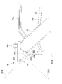
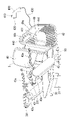
- FIG. 1 is a perspective view of an electric mobility according to one embodiment of the present invention; FIG. It is a side view of electric mobility of this embodiment. It is a top view of electric mobility of this embodiment.
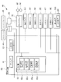
- 1 is a schematic diagram of a system in a passenger terminal T of this embodiment; FIG. It is a block diagram of the control unit of the electric mobility of this embodiment. It is a principal part perspective view of the passenger terminal T of this embodiment. It is a principal part side view of the electric mobility of the modification of this embodiment. It is a perspective view of the electric mobility of the modification of this embodiment. It is a side view of the electric mobility of the modification of this embodiment. It is a partial perspective view of the electric mobility of the modification of this embodiment. It is a partial plan view of the electric mobility of the modification of this embodiment.
- the system includes, as shown in FIG. 4, a plurality of electric mobilities M arranged in a passenger terminal T of an airport, and a management computer 100 that manages the plurality of electric mobilities M.
- Management computer 100 need not be located at the airport.
- the electric mobility M of this embodiment will be briefly described. In addition, in the said system, it is also possible to use electric mobility different from the electric mobility M of this embodiment.
- This electric mobility M includes a mobility body 30 having a pair of front wheels (wheels) 10 and a pair of rear wheels (wheels) 20, as shown in FIGS. Further, the mobility body 30 includes a seat unit (seat) S. Wheels may be provided in addition to the front wheels 10 and the rear wheels 20, and the numbers of the front wheels 10 and the rear wheels 20 may be other than those described above. Also, one of the front wheel 10 and the rear wheel 20 may be omitted.
- the electric mobility M of this embodiment is a type of electric wheelchair in which one user sits on the seat unit S and rides.
- the mobility body 30 has a motor (driving device) MT ( FIG. 5 ) for driving at least one of the pair of front wheels 10 and the pair of rear wheels 20 .
- the vehicle front-rear direction shown in FIG. 3 may be referred to as the front-rear direction in the following description, and the vehicle width direction illustrated in FIG. 3 may be referred to as the width direction or the left-right direction in the following description.
- the vehicle front-rear direction and the front-rear directions of the electric mobility M and the mobility main body 30 are the same, and the vehicle width direction and the width directions of the electric mobility M and the mobility main body 30 are the same.
- each pair of rear wheels 20 is connected to a motor MT, and each motor MT drives the corresponding rear wheel 20 .
- the driving force of each motor MT may be transmitted to the corresponding front wheel 10 by power transmission means.
- a power transmission means is a belt, a gear, or the like.
- Each front wheel 10 has a hub 14 attached to an axle (not shown) and a plurality of roller spindles (not shown) supported by the hub 14.
- a plurality of rollers 13 rotate on the roller spindles. supported as possible.
- the hub 14 may be attached to the axle using a bearing or the like, or the hub 14 may be attached to the axle using a buffer member, an intermediate member, or the like.
- the front wheel 10 is depicted simply in FIG.
- each roller 13 rotates around the axis of the corresponding roller support shaft. That is, the outer peripheral surface of each front wheel 10 is formed by a plurality of rollers 13, and each front wheel 10 is an omnidirectional wheel that moves in all directions with respect to the running surface.
- each rear wheel 20 includes an axle (not shown), a hub 21 attached to the axle, and an outer periphery provided on the outer peripheral side of the hub 21, the outer peripheral surface of which is formed using a material having rubber-like elasticity. 22, but like the front wheels 10, omni-directional wheels may also be used. In this case, the front wheels 10 are normal wheels instead of omnidirectional wheels.
- the axle of the rear wheel 20 may be common to the main axle of the motor MT.
- the structure of the mobility main body 30 can be changed as appropriate.
- the mobility body 30 of this embodiment has a base portion 32 extending along the ground, and a seat support portion 33 extending upward from the rear end side or central portion of the base portion 32 .
- a seat unit S is attached to the upper end side of the seat support portion 33 .
- the base portion 32 of this embodiment has a plastic cover portion that at least partially covers the metal base frame 32a shown in FIG. The cover portion is used as a portion on which the feet of a user sitting on the seat unit S are placed, a portion on which luggage is placed, and the like.
- the seat unit S has a backrest portion 40 and a seat surface portion 50 .
- the backrest portion 40 extends upward from the rear end of the seat portion 50 .
- the cushion 51 of the seat portion 50 is removable, and when the cushion 51 is removed, the upper surface of the seat support portion 33 and/or the lower structure of the seat portion 50 are exposed.
- the seat support portion 33 is formed with a vertically extending battery accommodating portion, and the battery BA (FIG. 5) is accommodated in the battery accommodating portion.
- a seating sensor 53 is provided at the upper end of the seat support portion 33 as part of the lower structure of the seat surface portion 50, as shown in FIG.
- the seating sensor 53 of this embodiment has a detection device.
- the sensing device may be a switch, pressure sensor, or the like. In this embodiment the sensing device is a switch.
- a known sensor of another mode that detects that the user has gotten on the cushion 51 may be used.
- the detection device when the user gets on the cushion 51, the detection device is pushed, and a predetermined signal (current) or the like is transmitted from the detection device to the control device 80, which will be described later.
- the seat unit S has a right control arm 43 and a left control arm 43 .
- An armrest 43 a is fixed to the upper surface of each control arm 43 .
- the user drives both arms on the armrests 43a of the pair of control arms 43, respectively.
- the user puts both hands on the upper ends of the pair of control arms 43 respectively.
- both the control arm 43 and the armrest 43a are provided in this embodiment, only the control arm 43 or the armrest 43a may be provided. In this case, the user can place at least one of the arm and hand on the control arm 43, or place at least one of the arm and hand on the armrest 43a.
- a controller 44 having an operating portion (joystick) 44a is provided at the upper end of one control arm 43 or armrest 43a.
- the controller 44 may be separated from the mobility main body 30.
- the controller 44 may be, for example, the user's tablet computer, a controller similar to a game controller, or the like.
- the operation unit 44a is not provided, and the user inputs the running direction, running speed, etc. of the electric mobility M using the touch screen function of the screen of the tablet computer.
- the controller 44 is separated from the mobility main body 30, it is also possible for another person, not the user, to operate the electric mobility M on which the user rides.
- a signal corresponding to the direction and amount of displacement of the operation portion 44a is transmitted from the controller 44 to the control unit 60, which will be described later, and the control unit 60 controls each motor MT according to the received signal.
- An interface (input device) 45 for making various settings related to electric mobility is provided at the upper end of the left control arm 43 or armrest 43a. Examples of various settings include maximum speed setting, driving mode setting, electric mobility lock setting, and the like.
- the interface 45 is provided with a plurality of operation buttons, a display device 200 such as a liquid crystal display device, and the like. As shown in FIG. 1, the display device 200 constituting the interface 45 is arranged to face upward.
- Information is transmitted to the display device 200 by wire or wirelessly from the control device 80, which will be described later, and the display device 200 displays the received information.
- the information includes, for example, information on the traveling speed of the electric mobility M, information on the state of the battery BA, and obstacles (avoidance targets) detected by sensors such as a front sensor 90, a rear sensor 95, and a lower sensor 96, which will be described later. location information, information on the result of judgment as to whether or not the obstacle will hinder travel, map information, travel route information, and the like.
- the display device 200 also has input means such as a touch screen function, and information input to the display device 200 is transmitted to the control device 80 .
- the positional information includes point cloud data (distance data of a plurality of points) obtained by the sensors 90 , 95 and 96 .
- the display device 200 may include a control device having a processor, a storage device, etc., and the control device may perform some or all of the functions of the control device 80 described later. Also, the display device 200 may be detachably attached.
- the control unit 60 has a motor driver 70 for driving each motor MT and a control device 80, as shown in FIG.
- Motor driver 70 is connected to battery BA.
- the motor driver 70 is also connected to each motor MT, and the motor driver 70 supplies drive power to each motor MT.
- the control device 80 includes a processor 81 such as a CPU, a storage device 82 having a nonvolatile memory, a ROM, a RAM, etc., and a transmitting/receiving section 83 for transmitting/receiving information by wireless communication and wired communication.
- a travel control program 82a for controlling the electric mobility M is stored in the storage device 82 .
- the processor 81 operates based on the traveling control program 82 a and transmits drive signals for driving the motors MT to the motor driver 70 based on signals from the controller 44 and the interface 45 .
- a front sensor 90 which is a three-dimensional distance sensor having a field of view of a predetermined angle in each of the vertical direction and vehicle width direction, is attached to the lower side of the right control arm 43 and the lower side of the left control arm 43, respectively.
- the front sensor 90 is a type of LiDAR (Light Detection and Ranging or Laser Imaging Detection and Ranging), emits laser light in various directions within the field of view, and detects each reflector based on the reflected light. Detect location.
- the front sensor 90 may be provided below the armrest 43a when the control arm 43 is not provided.
- the front sensors 90 are attached to the seat surface portion 50 of the seat unit S, the seat support portion 33, and the like, and the front sensors 90 are arranged below the seat surface 50a of the seat surface portion 50.
- FIG. It is sufficient that the laser beam emitting portion of the front sensor 90 is arranged below the seat surface 50a.
- the front side sensor 90 it is also possible to use a distance sensor such as a radar sensor or a millimeter wave sensor.
- the front side sensor 90 is a radar sensor, a millimeter wave sensor, or the like, it suffices that the detection wave emitting portion is arranged below the seat surface 50a.
- the front sensor 90 provided at this position is difficult for the user of the seat unit S to touch, and the field of view of the front sensor 90 is not easily obstructed by the bag held by the user, the user's sleeve, or the like. contributes to accurate and stable detection by
- each front sensor 90 has a field of view of 30° or more, preferably 50° or more from the center of a cone, pyramid, elliptical cone, etc., and the laser beam is emitted many times per second in various directions within the field of view. is emitted, the reflected light of each laser beam is received, and the position of each point where each laser beam is reflected is detected. That is, each front sensor 90 emits laser light in various directions in front of the vehicle and on the sides of the front wheels 10, and detects the positions of obstacles (objects to be avoided) in front of the vehicle and on the sides of the front wheels 10 based on the reflected light. do.
- a known three-dimensional LiDAR can be used as each front sensor 90 .
- each front sensor 90 includes the seat surface portion 50, the seat support portion 33, part of the front wheel 10, part or all of the fender 15 of the front wheel, the legs of the user on the seat unit S, clothes including skirts, and the like. come in.
- the control device 80 or each front side sensor 90 is set to exclude the seat surface portion 50, the seat support portion 33, part of the front wheel 10, and part or all of the fender 15 of the front wheel from obstacles (objects to be avoided). .
- the range excluding a partial angle range (angle range in which the seat surface portion 50, the seat support portion 33, etc. exist) from the field of view of each front sensor 90 is defined by each front sensor. 90 detection range DA1.
- the control device 80 is set so as not to recognize the front wheel 10, the fender 15 of the front wheel, the user's legs, clothes, etc. as obstacles.
- the detection range DA1 of each front sensor 90 is the front of the electric mobility and the front wheels 10 and the outside of the front wheels 10 in the width direction (FIGS. 2 and 3). As described above, the inner range of the field of view of each front sensor 90 in the vehicle width direction is blocked by the seat surface portion 50, the seat support portion 33, and the like. Therefore, in one example, the detection range DA1 is 5° or more and 20° or less toward the vehicle inner side and 30° or more and 90° or less toward the vehicle outer side with respect to the vehicle front-rear direction in a plan view.
- the detection range DA1 is a range of 5° or more upward and 30° or more and 90° or less downward with respect to the horizontal plane. In one example, the detection range DA1 is 60° or less upward with respect to the horizontal plane.
- each front side sensor 90 faces obliquely outward and obliquely downward.
- the angle of inclination is 5° or more outward and 5° or more downward. In one example, the angle of inclination is, in one example, no more than 30° outward and no more than 30° downward. This configuration is useful for the front sensors 90 to accurately detect obstacles on the outside and in front of the front wheel 10 in the width direction.
- the mobility main body 30 has a luggage placement section 42 that is a luggage basket.
- the luggage placement part 42 is supported by the rear end of the mobility body 30 and/or the back of the seat unit S.
- the luggage placement portion 42 extends vertically along the backrest portion 40 and has a front side wall 46 that restricts forward movement of luggage inside the vehicle.
- the front wall 46 may be a backrest portion 40, and the backrest portion 40, together with the front wall 46, may restrict the forward movement of luggage inside the vehicle. This structure is useful for making the electric mobility compact in the front-rear direction.
- the luggage placement portion 42 has a lower wall 47 extending rearward of the vehicle from the lower end of the front wall 46 and a rear wall 48 extending upward from the rear end of the lower wall 47 .
- the top of the rear wall 48 is lower than the top of the front wall 46 .
- the front wall 46 and the rear wall 48 are separated in the front-rear direction by 20 cm or more, preferably 25 cm or more.
- the luggage placement section 42 has a pair of side wall sections 49 facing each other in the width direction.
- each side wall portion 49 widthwise closes the space formed by the front side wall 46 , the lower side wall 47 and the rear side wall 48 .
- At least part of luggage is stored in the space formed by the front wall 46, the lower wall 47, the rear wall 48, and the pair of side walls 49.
- the luggage placement portion 42 itself is small, a slightly large luggage such as a suitcase for carry-on into the aircraft can be stably placed on the luggage placement portion 42 .
- a LiDAR rear sensor 95 is attached to the seat support section 33 of the mobility main body 30 below the seat unit S or below the luggage placement section 42 .
- the rear sensor 95 emits laser light over the detection range DA2 in FIG. 3, and the rear sensor 95 detects the reflected light that hits and reflects from the object.
- the control device 80 uses the detection result (detection data) to detect the position of the obstacle (avoidance target) in the detection range DA2, which is the outside and the rear of the electric mobility in the width direction.
- Obstacles are, for example, people, animals, plants, people's clothes, people's belongings, and the like. Obstacles are, for example, walls, relatively large objects, and steps.
- the rear sensor 95 may detect obstacles (avoidance targets) such as steps, holes, grooves, etc., into which the rear wheel 20 may fall or get stuck.
- the obstacles are detected by the front sensors 90 over the detection range DA1 in FIG. 3, and the obstacles are detected by the lower sensor 96 over the detection range DA3, which will be described later.
- a lower sensor 96 is attached to the lower surface of the electric mobility M.
- the lower sensor 96 is a LiDAR attached to the bottom surface of the footrest portion of the base portion 32, the bottom surface of other portions of the base portion 32, or the like.
- the lower sensor 96 is arranged below the footrest surface 32c of the footrest or the lower surface of the base portion 32.
- the laser light (detection wave) emitting portion of the lower sensor 96 is arranged below the footrest surface 32c.
- the lower sensor 96 is arranged substantially in the center of the electric mobility M in the vehicle width direction.
- the lower sensor 96 emits laser light over the detection range DA3 shown in FIG. That is, the lower sensor 96 detects the position of the obstacle (avoidance target) in the lower area in the range in front of the vehicle of the electric mobility M, which is outside the detection range DA1 of the pair of front sensors 90. It can be detected from the lower side of the mounting surface 32c or from the lower side of the mobility body 30 .
- the lower sensor 96 emits a laser beam to the side of the vehicle from between the front wheel 10 and the rear wheel 20, and exists in the space between the front wheel 10 and the rear wheel 20, or can enter the space. possible obstacles can be detected.
- the detection range DA3 is a range of 30° or more in front of the vehicle between the pair of front wheels 10 when viewed from the lower sensor 96. 30° or more on the right side of the vehicle between the front wheels 10 and the rear wheels 20 and 30° or more on the left side of the vehicle. In one example, the detection range DA3 is a range of 90° or less on the front side of the vehicle, a range of 90° or less on the right side of the vehicle, and a range of 90° or less on the left side of the vehicle when viewed from the lower sensor 96 . In this embodiment, the detection range DA2 of the rear sensor 95 is a range of 180° or more behind the vehicle as viewed from the rear sensor 95, as shown in FIG.
- the emission position of the laser light (detection wave) of the rear sensor 95 is preferably above the upper end of the rear wheel 20 or the upper end of the fender of the rear wheel 20 . This configuration is useful for detecting obstacles present in the rear wheel vicinity area on the outside and behind the rear wheel 20 in the width direction. Further, the detection range DA1 of each front sensor 90 is the front of the electric mobility M and the front wheels 10 and the outside of the front wheels 10 in the width direction as described above. The emission position of the laser light (detection wave) of each front sensor 90 is preferably above the upper end of the front wheel 10 or the upper end of the fender of the front wheel 10, and/or the laser light (detection wave) of each front sensor 90.
- each front sensor 90 can detect an obstacle on the outside in the width direction of the front wheel 10 that cannot be seen from the lower sensor 96 . Also, each front sensor 90 can detect an obstacle in front of the front wheel 10 that is not visible from the lower sensor 96 .
- the detection ranges of the sensors 90, 95, 96 are formed so as to substantially cover the entire circumference of the electric mobility M. It is difficult for the knees of the user on the seat unit S to be placed on the line connecting each of the front sensors 90 and the front wheel vicinity area on the outside in the width direction of the front wheel 10 .
- the front sensors 90 are provided at the upper end side and the front end of the control arm 43, the knees of the user on the seat unit S are located on the line connecting the front sensors 90 and the area near the front wheels. Easy to place. That is, the configuration of this embodiment is useful for accurate detection of obstacles in the area near the front wheels.
- the front wheels 10 are omnidirectional wheels. For example, when the pair of rear wheels 20 are rotated in opposite directions by the motor MT, the front wheels 10 move in the directions of their rotation axes. In the present embodiment, with the above configuration, obstacles in the area near the front wheels are detected by the respective front sensors 90, and this configuration is useful for safe and smooth movement of the electric mobility M.
- the height from the floor of the emission position of the laser light (detection wave) of each front sensor 90 is 20 cm or more, and preferably 60 cm or less.
- the rear sensor 95 and the lower sensor 96 are two-dimensional LiDARs.
- the configuration is more effective when the electric mobility M mainly moves forward during automatic operation or when it hardly moves backward.
- the detection light of the two-dimensional LiDAR is emitted obliquely upward when traveling forward of the vehicle.
- the angle between the emission direction of the detection light and the horizontal surface is preferably 1° or more, more preferably 2° or more. is more preferred. Further, in this embodiment, the angle is preferably set to 7° or less, more preferably 5° or less, in order to reliably detect the mark MK when no user is on the vehicle.
- the lower sensor 96 for self-position estimation, for example, when measuring the shape of a detection target of a structure such as a wall of a building about 10 m ahead, if the angle is 6° or more, the measurement position becomes too high. As a result, it will not be consistent with the map data acquired in advance.
- the angle is also useful for matching the map data stored or recognized by the control device 80 with the detection result of the lower sensor 96 . It is possible to set the angle outside the above numerical range as long as the same effect is achieved. With this configuration, even when a heavy user sits on the seat unit S and the arrangement angle of the lower sensor 96 changes due to this, the lower sensor 96 recognizes the floor surface in front of the vehicle as an obstacle. less likely to.
- the sensors 90, 95, 96 also detect glass windows, glass doors, etc., which is useful for preventing the electric mobility M from colliding.
- the rear sensor 95 and the lower sensor 96 are two-dimensional LiDAR, but it is also possible to use distance sensors such as three-dimensional LiDAR, radar, and millimeter wave sensors.
- the control device 80 operates based on an avoidance control program 82b and an automatic driving program 82c stored in the storage device 82.
- the control device 80 creates or obtains a distance image (detection data) based on the detection results (detection data) of the sensors 90, 95, and 96. FIG. Then, the control device 80 detects the position of the obstacle (avoidance target) with respect to the electric mobility M in the distance image.
- the control device 80 converts the data (detection data) obtained by the sensors 90, 95, and 96 within the detection ranges DA1, DA2, and DA3 into a two-dimensional planar image that indicates the distance to the electric mobility M ( distance image) to recognize the position of the obstacle. Further, the position of the obstacle may be recognized by treating the data as data in a three-dimensional space. Controller 80 may recognize obstacles detected within detection ranges DA1, DA2, and DA3 by other methods.
- the control device 80 uses the detection results of the GPS receiver, the odometer, the sensors 90, 95, 96, etc. provided in the electric mobility M to store in the storage device 82 Perform self-position estimation on the stored airport map data. Self-position estimation can be performed by a known method. In addition, based on the automatic driving program 82c, the control device 80 uses the detected obstacles, the map data stored in the storage device 82, and the results of the self-position estimation to determine, for example, from the departure point to the destination. route setting and automatic driving can be performed.
- the control device 80 uses the lower sensor 96 to detect marks MK provided on at least the surfaces extending in the vertical direction, such as walls, pillars, and steps of the airport (facility). is configured to It is also possible to configure so that the detection of the mark MK below is performed by the rear sensor 95 instead of the lower sensor 96 .
- the surface extending obliquely upward is also a surface extending at least in the vertical direction.
- a plurality of types of marks MK are arranged at respective positions in the airport.
- Control device 80 may automatically detect the position of mark MK with respect to electric mobility M when mark MK is placed within detection range DA3. Alternatively, the control device 80 may detect the position of the mark MK when an operator inputs to an input device such as the display device 200 .
- each mark MK is a barcode-like mark (one-dimensional code).
- a plurality of black vertical lines are arranged in the horizontal direction, and the pattern differs for each mark MK.
- the lower sensor 96 which is a LiDAR, emits laser light to multiple locations on the mark MK. Then, the lower sensor 96 detects the intensity of the reflected light from each of the plurality of locations and also detects the positions of the electric mobility M at the plurality of locations. If the color of the surface provided with the marks MK is white, for example, the intensity of the reflected light from the black vertical lines will be lower than the intensity of the reflected light from the white portion of said surface.
- Control device 80 detects the position and type (pattern) of mark MK with respect to electric mobility M based on the intensity and position of reflected light at a plurality of locations. That is, the control device 80 recognizes the position of the electric mobility M with respect to the mark MK. Various patterns can be used as the mark MK.
- the lower sensor 96 may be a millimeter wave sensor, radar sensor, or the like. In this case also, the lower sensor 96 emits detection waves to the front and to the sides of the vehicle to detect the position of the obstacle in front of the vehicle as described above. Or to detect obstacles that may enter. In one example, the direction of the element (antenna) that receives the detection wave of the lower sensor 96 is mechanically changed. Also, the lower sensor 96 emits a detection wave toward the mark MK. Then, the lower sensor 96 detects the intensity of each reflected wave from the plurality of locations, and also detects the positions of the electric mobility M at the plurality of locations.
- each mark MK has, for example, a plurality of detection wave absorbing portions arranged in the horizontal direction.
- Control device 80 detects the position and type (pattern) of mark MK with respect to electric mobility M based on the intensities and positions of reflected waves at a plurality of locations.
- the control device 80 controls the electric motor on the map data. Position the mobility M. Therefore, self-position setting on the map data is ensured.
- the mark MK itself does not require a power supply, and a separate device for self-position setting is not required.
- each mark MK is placed at a low position visible from the lower sensor 96 . Therefore, each mark MK is not conspicuous in the airport, and the mark MK is effectively prevented from being soiled or faded due to being touched by a person's hand or leaning on it.
- the height of the lower end of each mark MK from the floor is preferably 0 cm or more and 30 cm or less.
- the height from the floor of the lower sensor 96 where the laser light (detection wave) is emitted is 2 cm or more and 20 cm or less, and the mark MK can be easily detected from such a lower sensor 96 .
- the height from the floor of the lower end of each mark MK is 50 cm or less.
- the height from the floor of the laser beam (detection wave) emitting portion of the rear sensor 95 is 40 cm or less, and the above mark MK can be easily detected from such a rear sensor 95 .
- each mark MK is preferably 10 cm or more, more preferably 20 cm or more.
- the vertical dimension of each mark MK is also preferably 10 cm or more. Thereby, detection of the position of the mark MK with respect to the electric mobility M becomes more accurate.
- the mark MK may be a mark other than a barcode-like mark.
- the mark MK has two or more colors arranged in the horizontal direction, it is also possible to use a mark MK consisting of two or more kinds of chroma, lightness, or reflectance parts arranged in the horizontal direction.
- each mark MK can be formed from a plurality of horizontally arranged retroreflective tapes. In this case, the mark MK becomes inconspicuous to passersby.
- the user designates a destination (destination) using the input device 201 (FIG. 5) provided in the display device 200, and the control device 80 determines the route from the current self-position starting point to the destination. Perform settings and automatic operation. In some cases, the destination is set in advance.
- the input device 201 can be, for example, a touch screen function of the display device 200 or a button provided on the display device 200 . Instead of the input device 201, an input device such as a button provided on the controller 44 or the like may be used.
- the control device 80 detects the obstacle in a predetermined range of the detection ranges DA1, DA2, and DA3, for example, based on an avoidance control program 82b stored in the storage device 82 during automatic operation or manual operation of the electric mobility M.
- each motor MT is controlled by a control command for avoidance action and/or an alarm device is activated.
- avoidance actions include reducing or stopping the rotational speed of each motor MT to avoid the avoidance target (automatic stop function), and controlling each motor MT to limit the movement of the electric mobility M toward the avoidance target. be.
- the object to be avoided exists at a distance closer than a predetermined distance (1 m, several tens of centimeters, etc.) to the sensor, the electric mobility M, etc., and is likely to hinder the traveling of the electric mobility M. Obstacles, etc.
- control device 80 can detect an obstacle (avoidance target) existing between the front wheels 10 and the rear wheels 20 in the detection range DA3 based on the avoidance control program 82b during automatic driving or manual driving of the electric mobility M. is.
- the control device 80 can detect an obstacle (avoidance target) that may enter the space between the front wheels 10 and the rear wheels 20 .
- obstacles that may enter are obstacles that are less than a predetermined short distance from the space, such as less than 10 cm or less than 20 cm.
- Another example is an obstacle that is heading towards the space and, given its distance and speed, may enter the space within a predetermined short period of time, such as within 5 seconds.
- the control device 80 performs the avoidance operation, the activation of the notification device, and the like.
- This arrangement prevents the rear wheels 20 from running over the feet of pedestrians, for example.
- the electric mobility M moves backward, the front wheels 10 are prevented from running on the foot of the pedestrian.
- the electric mobility M looks smart and the weight of the electric mobility M can be reduced.
- the control device 80 Based on the avoidance control program 82b, the control device 80 detects obstacles (objects to be avoided) existing behind the rear wheels, obstacles that may enter the vicinity space behind the rear wheels, etc., in the detection range DA3. You may
- the single lower sensor 96 detects the position of the obstacle (avoidance target) in the lower area in front of the electric mobility M vehicle.
- an obstacle that exists between the front wheel 10 and the rear wheel 20 or an obstacle that may enter is also detected.
- the position and direction of the electric mobility M are set accurately on the map data.
- the front sensor 90 whose field of view is less likely to be blocked by the bag or the like held by the user, detects obstacles in front of and to the sides of the front wheels 10, and the lower sensor 96 detects the lower side of the electric mobility M in front of the vehicle.
- a configuration in which an obstacle in an area is detected can reliably avoid contact with an inconspicuous sensor in a facility.
- the front sensor 90 may be provided at other portions such as the upper end of each control arm 43, the front end of the armrest 43a, the intermediate portion in the front-rear direction, or the like. If the control arm 43 is not provided, the front side sensor 90 may be provided at the front end portion of the armrest 43a, the middle portion in the front-rear direction, or the like. Even in these cases, a portion of the field of view of each front sensor 90 is blocked by the legs, clothing, etc. of the user on the seat unit S.
- the detection range DA3 of the lower sensor 96 covers the area below the blocked range, that is, the area below the range of the electric mobility M in front of the vehicle.
- the upper edge 49a of the side wall portion 49 of the luggage placement portion 42 is inclined downward toward the rear of the vehicle. Therefore, when the straps of the luggage placed in the luggage placement portion 42 hang down outside the luggage placement portion 42, the straps are highly likely to hang backwards rather than laterally of the luggage placement portion 42. Become. That is, even if the hanging strap is placed on the side wall portion 49, the strap moves toward the rear side wall 48 due to the inclination of the upper edge 49a. Therefore, the possibility that the hanging strap is stepped on by the rear wheel 20 is reduced. It should be noted that the electric mobility M mainly moves forward, and the strap is likely to be stepped on during forward movement.
- the sagging strap is stepped on by the rear wheel 20, it may lead to damage to the luggage and failure of the rear wheel 20. Even if the upper edge 49a has a plurality of steps that are lowered toward the rear of the vehicle, the effect of moving the hanging strap toward the rear of the vehicle can be achieved in the same manner as described above. Vibration or the like during running of the electric mobility M assists the movement of the strap toward the rear of the vehicle by the upper edge 49a.
- a dangling strap may be detected as an obstacle by the rear sensor 95, a situation that is not favorable for accurate obstacle detection.
- the side wall portion 49 may be formed of a net made of metal, plastic, fiber, or the like, or a plurality of strings. Even in this case, it is possible to form the upper edge 49a that is lowered toward the rear of the vehicle by the upper end of the net or the uppermost string.
- a mark MK may be provided at least one of the entrance and exit of the no-entry area such as the moving walkway MW. Stairs, escalators, etc. are examples of no-entry areas.
- marks MK are provided on the surfaces extending in the vertical direction on the lower end sides of the poles on both sides of the entrance of the moving walkway MW.
- the control device 80 detects the position of the mark MK with respect to the electric mobility M as described above when the electric mobility M is automatically operated or manually operated. Thereby, the control device 80 can recognize the position of the electric mobility M with respect to the moving walkway MW.
- the control device 80 controls each motor MT so that the electric mobility M does not enter the moving walkway MW. For example, when the electric mobility M is about to enter or exit the moving walkway MW, the control device 80 controls each motor MT according to the control command for the avoidance operation and/or activates an alarm device.
- a piece of retroreflective tape may be attached to each of the two poles. If each retroreflective tape has a different size, each functions as a unique mark MK. Alternatively, the two retroreflective tapes respectively attached to the two poles are separated from each other by a predetermined distance in the horizontal direction. A reflective tape can serve as one mark MK. Thus, in this embodiment, the single lower sensor 96 is also used to prevent entry into the moving walkway MW.
- the moving walkway MW has a width that allows the electric mobility M to enter, but the controller 80 controls each motor MT so that the electric mobility M does not enter the moving walkway MW (intrusion prohibited area). do.
- the control device 80 can perform the control by various control methods. For example, the control device 80 recognizes that there is an obstacle (no entry area) such as a wall between the two retroreflective tapes. Alternatively, the control device 80 recognizes an area between the two retroreflective tapes or a range within a predetermined distance (several meters or less, 1 m or less, etc.) from the line as the no-entry area. For example, the no-entry area may be recognized when the distance between the retroreflective tapes is equal to or less than a predetermined distance.
- control device 80 estimates the self-position using a detection result using some equipment such as a GPS receiver, an odometer, and sensors 90, 95, and 96 provided in the electric mobility M, and the estimated self-position is Recognizing the position of the keep-out area relative to its own position and/or the controller 80 recognizes the keep-out area as an obstacle in the detection space that is detected and recognized by the sensors 90 , 95 , 96 . Therefore, the actual distance between electric mobility M and the no-entry area is likely to match the recognition of control device 80 . On the other hand, it is also possible to set the recognized no-entry area on the map data. In this case, the actual distance between electric mobility M and the no-entry area may deviate from the recognition of control device 80 by the amount of deviation in self-position estimation.
- some equipment such as a GPS receiver, an odometer, and sensors 90, 95, and 96 provided in the electric mobility M
- the estimated self-position is Recognizing the position of the keep-out area relative to its own position and
- the controller 80 maintains the position of the recognized no-go area for a certain period of time or until it leaves the no-go area for a certain distance. By maintaining the position of the prohibited area, wasteful movements such as the electric mobility M returning to the prohibited area can be avoided.
- the height of the pole is considered to be in the range of 70 cm to 120 cm in many cases, the lower end side of the pole is naturally lower than the center of the pole.
- the retroreflective tape is usually provided within a range of 50 cm or less from the bottom end of the pole, preferably within a range of 35 cm or less from the bottom end of the pole. It is rare that the retroreflective tape is stuck at such a low position at regular intervals, and this enables accurate recognition of the no-entry area.
- the two retroreflective tapes may be attached to the pillars, walls, etc. on both sides of the entrance of the store, and the two retroreflective tapes may be attached to the pillars, walls, etc. on both sides of the door using glass or an automatic door. May be pasted.
- a plurality of retroreflective tapes may be attached to the windows of facilities such as airports, and the plurality of retroreflective tapes may be separated from each other by a predetermined distance in the horizontal direction. Even in this case, the control device 80 recognizes areas corresponding to store entrances, doors, automatic doors, windows, etc. as the no-entry areas based on the positions of the retroreflective tapes, as described above.
- a reflective tape capable of efficiently reflecting the detected waves toward the sensors 90, 95 and 96 may be used instead of the retroreflective tape.
- an upper sensor 97 may be provided at the upper end of one or both of the control arms 43, as shown in FIG.
- the upper sensor 97 is a three-dimensional distance sensor such as a three-dimensional LiDAR, a radar sensor, or a millimeter wave sensor in this embodiment, it may be a two-dimensional distance sensor such as a two-dimensional LiDAR.
- the upper sensor 97 detects an obstacle (avoidance target) present above the detection range DA3 of the lower sensor 96 in front of the vehicle of the electric mobility M.
- obstacles are table tops, ropes supported by a plurality of poles, and the like. The legs of the table, the lower end of the pole, etc.
- the control device 80 Since the electric mobility M moves in various directions, based on the detection result of the front sensor 90, the control device 80 stores upper obstacles that may not be detected by the lower sensor 96 on the map data. It is also possible to keep Alternatively, it is possible to attach the mark MK to a supporting portion such as a table leg or a pole that supports an upper obstacle that cannot be detected by the lower sensor 96 . In this case, based on the position and type (pattern) of the mark MK detected by the lower sensor 96, the control device 80 controls each motor MT according to the control command for the avoidance operation for the upper obstacle, the notification, etc. I do.
- the display device 200 is arranged to face upward. Further, in this embodiment, the display device 200 is attached to the upper end portion of the control arm 43 on which the user puts his or her hand, for example, the front end side. If the control arm 43 is not provided, the display device 200 may be attached to the upper surface of the armrest 43a on the front end side. In these cases, the user of the seat unit S can operate the buttons and the touch screen of the display device 200 without bending the back of the hand backward, which leads to improved convenience for the user.
- This system can be applied to various passenger terminals T.
- the system will be described using the schematic diagram of a passenger terminal T shown in FIG.
- the electric mobility M is used in the space after the security inspection of the passenger terminal T, but the electric mobility M may be used in other spaces of the passenger terminal T.
- a management station (rental station) 2 is provided near the exit of the security screening area 1, and a plurality of electric mobilities M are arranged in the management station 2.
- the management station 2 also has a reception desk 3, and a computer 4 is installed in the reception desk 3.
- the computer 4 is a known computer such as a laptop computer, tablet computer, or the like.
- the computer 4 is connected to the management computer 100 via a communication network, communication line, or the like.
- Management data for managing a plurality of electric mobilities M is stored in the storage device of the management computer 100 .
- the management data is data for displaying the management table on the display device 5 of the computer 4 or the display device of the management computer 100 .
- the management table includes a timetable. Identification information (identifiers) of a plurality of electric mobility M are described in a plurality of rows of the management table. Usage status (usage information), flight information written on the user's boarding pass, etc. are displayed. The flight information can also be said to be information including information on the user's destination, time information on the desired arrival time at the destination, and the like.
- the electric mobility M that has finished being used by the user moves toward a predetermined waiting location by automatic operation.
- the end of use by the user is determined by the control device 80 based on the detection result of the seating sensor 53, the user's input to the input device such as the display device 200, and the like. For example, when the seating sensor 53 does not detect the user's seating for a predetermined period of time, it is determined that the use has ended.
- the electric mobility M moving toward a predetermined standby location often moves forward rather than backward.
- the sensors for automatic driving are inconspicuous in the electric mobility M, and this is because the user cannot use the electric mobility M. Useful for comfortable use. At least some of the users are concerned about the appearance of the electric mobility M, the appearance of the electric mobility M with the user riding on it, and the like. It is also possible to use a three-dimensional LiDAR provided above the head of the user on the seat unit S instead of the sensors 90 and 95, for example. However, in this case, the height dimension of the electric mobility M cannot be reduced due to the presence of the three-dimensional LiDAR, which may increase the weight of the electric mobility M and reduce the stability of the electric mobility M.
- the presence or absence of a user on the seat unit S may be detected by the front sensor 90 without providing the seating sensor 53 .
- the said service using the electric mobility M may be provided in facilities other than the passenger terminal T.
- the service may be provided within facilities such as hospitals, train stations, and the like.
- the service may also be provided at outdoor facilities such as amusement parks, outdoor art museums, universities, and concept towns.
- the electric mobility M may be used at places other than the facility.
- the above-described configuration may be adopted for the electric mobility M purchased by the user instead of the rented electric mobility M.
- a plurality of waiting places may be provided.
- a waiting place may be provided at a position corresponding to each gate.
- a place where the electric mobility M can wait may be found, and the found place where the electric mobility M can wait may be used as the waiting place.
- Such waiting areas include spaces by walls.
- the luggage placement portion 42 becomes smaller in the longitudinal direction of the vehicle, and the rear sensor 95 is attached to the lower surface of the boarding base or the like.
- a user standing on the boarding base can operate the operation unit 44a or the display device 200 for manual driving or automatic driving of the electric mobility M.
- the electric mobility M may not be provided with the seat unit S.
- a large luggage rest 42 or luggage bin may be provided on the mobility body 30 .
- the lower sensor 96 can detect an obstacle that exists in the space between the front wheels 10 and the rear wheels 20 or that may enter the space.
- the lower sensor 96 is directed from between the front wheels 10 and the rear wheels 20 toward the outside of the vehicle as in the above embodiment.
- a laser beam detection wave
- the space is in front of the rear wheel 20
- the space is behind the front wheel 10 .
- a first sensor 301 may be provided at a predetermined position of the electric mobility M as the upper sensor 97 .
- the first sensor 301 can emit a known first detection wave 301a such as a laser beam, an ultrasonic wave, or an electric wave upward.
- a first distance to the reflection position of the reflected wave can be detected.
- a first sensor 301 is provided at the front end of the control arm 43 or the front end of the armrest 43a.
- the predetermined position is a place where detection of the first distance is unlikely to be hindered by the user. More specifically, as shown in FIGS.
- the display device is positioned between the portion on which the left hand of the user seated on the seat unit S is placed and the first sensor on the left side. 200 screens are arranged. This configuration makes it difficult for the user to interfere with the detection of the first distance.
- the second sensor 302 may be provided on the electric mobility M, for example, the control arm 43 or the armrest 43a.
- the second sensor 302 can emit a known second detection wave 302a such as a laser beam, an ultrasonic wave, or an electric wave downward.
- a second distance to a second sensor detection position 302b on the floor outside the direction can be detected.
- the distance between the second sensor detection position 302b and the front wheel 10 is preferably less than 20 cm. It is also possible to make the said distance into 20 cm or more. However, the distance is preferably less than 20 cm in order to improve the riding comfort of the user, because the electric mobility M will frequently perform the avoidance operation described below unnecessarily.
- a third sensor 303 may be provided on, for example, the control arm 43 or the armrest 43a of the electric mobility M.
- the third sensor 303 can emit a known third detection wave 303a such as a laser beam, an ultrasonic wave, or an electric wave downward and in front of the vehicle.
- a third distance to the third sensor detection position 303b on the surface can be detected.
- the distance between the third sensor detection position 303b and the electric mobility M is preferably less than 120 cm. It is also possible to set the distance to 120 cm or more. However, since the electric mobility M often performs the following avoidance operation, the distance is preferably less than 120 in order to improve the riding comfort of the user.
- the positions of the sensors 302 and 303 are locations where detection of the second distance and the third distance is less likely to be obstructed by the user. Further, as shown in FIG. 8, the sensors 301, 302, 303 are provided on the pair of control arms 43 or the pair of armrests 43a, respectively. Sensors 301 , 302 and 303 are each connected to controller 80 .
- the control device 80 controls the control command for the avoidance operation.
- Control motor MT In one example, the first reference distance is set to some distance of 120 cm or less. In this embodiment, in the examples of FIGS. 7 and 8, the first reference distance is set to a distance of 50 cm or less, preferably 30 cm or less.
- the top plate makes the first distance equal to or less than the first reference distance, and it is possible to avoid collision of the user of the electric mobility M with the top plate.
- the control device 80 performs control for the avoidance operation.
- Each motor MT is controlled by a command.
- the descending structure detection criteria are for detecting descending structures.
- the descending structure includes descending steps, steep descending slopes, etc., and the descending steps include stairs.
- a steep downhill slope is a downhill slope of 15° or more or 20° or more with a height change of 3 cm or more.
- the control device 80 stops the electric mobility M, for example.
- the descending structure detection criterion is such that the irradiation position of the second detection wave 302a crosses the descending structure, so that the irradiation position is lower than a predetermined height from the floor surface on which the front wheels 10 of the electric mobility M are grounded. It corresponds to the change in the second distance when moving to the lower floor surface or the like. The change is set according to the moving speed of the electric mobility M. The change in the third distance is similar to the change in the second distance. It is preferable that the predetermined height is 3 cm or more. For example, the electric mobility M is prevented from entering a step of 3 cm or more, and the electric mobility M is also avoided from entering a steep downward slope where the height changes by 3 cm or more.
- the sensors 301, 302, 303 are distance sensors such as TOF sensors that can detect the distance to a point.
- the sensors 301, 302, and 303 irradiate a detection wave to a point or an area corresponding to the point, and detect the distance based on the reflected wave from the irradiation position. Therefore, it is possible to reduce the amount of information processing related to the detection results of the sensors 301, 302, and 303, which can be realized at low cost. Further, if distance sensors capable of detecting the distance to a certain point are used as the sensors 301, 302, and 303, the situation obtained by the detection becomes clear, and the reliability of the avoidance action is improved. It is also possible to use visual sensors as the sensors 301, 302 and 303 and detect the first to third distances by the visual sensors.
- the first detection wave 301a is emitted obliquely upward toward the front of the electric mobility M, and when the electric mobility M is viewed from the side, the first detection wave 301a has an inclination angle of 45° with respect to the horizontal direction. That's it. As a result, the top plate or the like existing in the traveling direction of the electric mobility M is reliably detected.
- the second detection wave 302a is emitted obliquely downward toward the side of the electric mobility M, and when the electric mobility M is viewed from the front, the second detection wave 302a has an inclination angle of 60° with respect to the horizontal direction. That's it. As a result, the descending structure present on the side of the front wheel 10 is reliably detected.
- the third detection wave 303a is emitted obliquely downward toward the front of the electric mobility M, and when the electric mobility M is viewed from the side, the third detection wave 303a has an inclination angle of 45° with respect to the horizontal direction. That's it.
- the descending structure or the like existing in the traveling direction of the electric mobility M is reliably detected.
- the height of the sensors 301, 302, and 303 from the floor surface is preferably 50 cm or more, and more preferably 60 cm or more. This height position is advantageous for detection of the top plate and descending structure.
- a wired controller 400 for an assistant may be connected to the electric mobility M as shown in FIG.
- the wired controller 400 has a joystick 410 for controlling the traveling direction and speed of the electric mobility M, and a release button 420 that enables control with the joystick 410 .
- the electric mobility M can be operated with the joystick 410 only while the release button 420 is pressed.
- the assistant holds the main body of the wired controller 400 with one hand, presses the release button 420 with the index finger, and operates the joystick 410 with the thumb.
- Other types of controllers can also be used as wired controller 400 .
- An example of an assistant is someone who works at a facility such as an airport.
- an assistant controls the electric mobility M on which the user is seated by operating the wired controller 400 .
- Wired controller 400 is also connected to electric mobility M by cable 430 .
- the assistant can easily recognize the location of the wired controller 400, and loss of the wired controller 400 can be prevented.
- hidden commands, hidden menus, and the like may be set in the display device 200 and the like.
- electric mobility M can be operated by wired controller 400 only when a hidden command, hidden menu, or the like is operated. This prevents incorrect use of the wired controller 400 by an unintended person such as a user sitting on the electric mobility M.
- the automatic stop function may be disabled when the electric mobility M becomes operable by the wired controller 400 . Thereby, the user and the electric mobility M can move more smoothly in a narrow passage.
- a grip portion 49b may be provided on each of the pair of side wall portions 49 of the luggage placement portion 42, and a switch 440 may be provided on each of the left and right grip portions 49b.
- the switches 440 are each connected to the controller 80 .
- grip portion 49b is provided along upper edge 49a and switch 440 is configured to be depressed when grip portion 49b is gripped.
- the control device 80 releases the brake of each motor MT.
- the brake is an electromagnetic brake or the like provided in each motor MT. As a result, the assistant can move by pushing the electric mobility M safely and easily.
- a downward surface 43b may be provided at the front end of the control arm 43, and a drive recorder camera 500 may be provided below and near the surface 43b.
- camera 500 is connected to controller 80 and images from camera 500 are stored in storage device 82 .
- the image of camera 500 is stored in the camera's own storage device or in another storage device. In such electric mobility, there is an advantage that the field of view of the camera 500 at the above position is less likely to be blocked by the user, and information about the vicinity of the front wheels 10 can be easily obtained.
- the second sensor 302 and the third sensor 303 are provided on the downward surface 43b of the control arm 43, as shown in FIGS.
- the control arm 43 is a part on which a user sitting on the seat unit S places his or her hand or arm.
- the surface 43b is provided on the lower surface of the armrest 43a.
- a shielding plate 43c directed downward from the surface 43b may be provided.
- the shielding plate 43c extends downward by 3 cm or more from the surface 43b and is arranged inside the second sensor 302 and the third sensor 303 in the vehicle width direction.
- the distance in the vehicle width direction between the second sensor 302 and the third sensor 303 and the shield plate 43c is 10 cm or less, more preferably 5 cm or less.
- This configuration prevents part of the user seated on the seat unit (seat) S, clothing, etc. from entering the detection range of the sensors 302 and 303.
- Some of the users are legs, knees, and the like.
- the user's clothes are trousers, skirts, and the like.
- the detection ranges of the sensors 302 and 303 are small.
- the detection range of the sensors 302 and 303 in which some of the users may enter is a range of about 1 cm in diameter centered on the optical axis of the sensors 302 and 303 . Therefore, the shield plate 43c effectively prevents a portion of the user from entering the detection range of the sensors 302 and 303.
- FIG. The posture of the user on the seat unit S, the clothes of the user, the physique of the user, the nationality of the user, etc. vary, and the above configuration contributes to stable use of electric mobility.
- the vertical distance D between the lower end of the shielding plate 43c and the seat surface 50a of the seat unit S is preferably 10 cm or less, more preferably 8 cm or less, and 5 cm or less. It is even more preferable to have
- a container 450 for housing the joystick 410 may be provided in the luggage placement section 42 .
- the wired controller 400 that is not in use is housed in the container 450 .
- Adopting a configuration in which the wired controller 400 is housed in the container 450 saves the trouble of the assistant looking for the joystick 410 and the trouble of storing it. This is useful for the assistant who performs various tasks in a limited amount of time.
- the lid 451 of the container 450 may be locked with a key or the like. In this case, only a specific assistant who has a key or the like can unlock.
- FIG. 10 shows an example of an electric mobility in which the controller 44 is not provided, and in FIG. 10 some parts such as a cover are removed.
- the display device 200 displays a mode display 202 indicating whether or not the electric mobility is in the manual push mode in which the electric mobility can be manually pushed, along with the display of the remaining battery level.
- the electric mobility is set to the manual push mode.
- electric mobility that is not set to manual mode does not release the brake of each motor MT even if switch 440 is pressed for safety. Having the mode display 202 is useful for the assistant to work smoothly.
- FIG. 11 shows a state in which a user is seated on the seat unit S, and at this time, the lower side of the display is arranged on the user's side (first display direction).
- the display direction is the second display direction.
- the upper side and the lower side of the display are opposite to the first display direction.
- the upper side of the display is arranged inside the vehicle width direction in the display device 200 .
- the control device 80 may switch between the first display direction and the second display direction based on the detection result of the seating sensor 53 . Such switching of the display direction is useful for improving workability of the assistant.
- the control device 80 may display characters or a diagram on the display device 200 in the second display direction to indicate to people around the electric mobility M that they cannot ride.
- the characters or drawings may mean that boarding is prohibited.
- switching between the first display direction and the second display direction based on the detection result of the seating sensor 53 may not be performed by the assistant. It is useful for improving workability.
- the display device 200 is a tablet computer in this embodiment, the display device 200 may be a simple display device controlled by another computer.
- the touch screen function of tablet computers usually makes selections corresponding to the position where the finger is lifted from the screen. For example, when the finger is removed from the screen at the position of "cancel" in the countdown display of FIG. 11, "cancel" is selected. In this embodiment, a selection corresponding to the long-pressed position on the screen is also performed. For example, if the finger touches the position of the "cancel” button on the screen for more than a predetermined time, "cancel" is selected. This configuration is useful for reducing the stress of users who are not accustomed to operating tablet computers, such as the elderly.
- the countdown display in FIG. 11 has a remaining time display 203, and the remaining time display 203 displays the time until automatic operation starts. For example, the remaining time display 203 gradually decreases, and automatic operation starts when it reaches zero.
- the configuration is useful for reducing user's stress.
- automatic operation is started when the user selects a button for starting automatic operation displayed on the display device 200 .
- the control device 80 enables the user's automatic driving start operation. This configuration is useful for ensuring the safety of users, people and things around them.
- Front wheel 20 Rear wheel 30 Mobility main body 42 Luggage placement part 43c Shielding plate 44 Controller 44a Operation part 45 Interface 50 Seat surface 50a Seat surface 60 Control unit 80 Control device 81 Processor 82 Storage device 82b Avoidance control program 82c Automatic driving program 82d Position Recognition program 90 Front sensor 95 Rear sensor 96 Lower sensor 97 Upper sensor 100 Management computer 200 Display device 201 Input device 301 First sensor 302 Second sensor 303 Third sensor 400 Wired controller 450 Container 500 Camera M Electric mobility S Seat unit
Landscapes
- Engineering & Computer Science (AREA)
- Physics & Mathematics (AREA)
- General Physics & Mathematics (AREA)
- Remote Sensing (AREA)
- Radar, Positioning & Navigation (AREA)
- Electromagnetism (AREA)
- Computer Networks & Wireless Communication (AREA)
- Public Health (AREA)
- Veterinary Medicine (AREA)
- General Health & Medical Sciences (AREA)
- Animal Behavior & Ethology (AREA)
- Life Sciences & Earth Sciences (AREA)
- Health & Medical Sciences (AREA)
- Aviation & Aerospace Engineering (AREA)
- Automation & Control Theory (AREA)
- Automatic Cycles, And Cycles In General (AREA)
- Electric Propulsion And Braking For Vehicles (AREA)
Abstract
Description
例えば、一人乗り等の小型電動モビリティのシェアリングサービスを提供する場面では、利用者の体格、手荷物等が互いに大きく異なる。また、このようなシェアリングサービスでは、比較的短い説明を受けた後に電動モビリティを操作する場合が多い。
当該システムは、図4に示されるように、空港の旅客ターミナルT内に配置された複数台の電動モビリティMと、複数の電動モビリティMを管理する管理コンピュータ100と、を備えている。管理コンピュータ100は空港内に配置されていなくてもよい。
この電動モビリティMは、図1~図3に示されるように、一対の前輪(車輪)10および一対の後輪(車輪)20を有するモビリティ本体30を備える。また、モビリティ本体30は、座席ユニット(座席)Sを備える。前輪10および後輪20の他に車輪が設けられてもよく、前輪10および後輪20の数が前記以外であってもよい。また、前輪10および後輪20の一方が無くてもよい。本実施形態の電動モビリティMは、一人の利用者が座席ユニットSに着座して乗る電動車椅子の一種である。
モビリティ本体30は、一対の前輪10および一対の後輪20の少なくとも一方を駆動するためのモータ(駆動装置)MT(図5)を有する。
本実施形態では、各後輪20は、図示しない車軸と、車軸に取付けられたハブ21と、ハブ21の外周側に設けられ、外周面がゴム状弾性を有する材料を用いて形成された外周部材22とを有するが、前輪10と同様に全方向車輪を用いてもよい。この場合、前輪10が全方向車輪ではなく通常の車輪となる。後輪20の車軸はモータMTの主軸と共通でもよい。
本実施形態のベース部32は、図3に示される金属製のベースフレーム32aを少なくとも部分的に覆うプラスチック製のカバー部を有する。カバー部は、座席ユニットSに座る利用者の足を載せる部分、荷物を載置する部分等として使用される。
座席支持部33には、上下方向に延びるバッテリ収容部が形成され、バッテリBA(図5)がバッテリ収容部に収容される。
各コントロールアーム43の上面にはアームレスト43aが固定されている。例えば、利用者(運転者)は一対のコントロールアーム43のアームレスト43aに両腕をそれぞれ置く。また、利用者は一対のコントロールアーム43の上端に両手をそれぞれ置く。本実施形態ではコントロールアーム43とアームレスト43aの両方が設けられているが、コントロールアーム43又はアームレスト43aのみが設けられていてもよい。この場合、利用者は、コントロールアーム43の上に腕および手の少なくとも一方を置き、又は、アームレスト43aの上に腕および手の少なくとも一方を置くことができる。
図1に示されるように、インターフェイス45を構成する表示装置200は上方を向くうように配置されている。
モータドライバ70はバッテリBAに接続されている。また、モータドライバ70は各モータMTにも接続されており、モータドライバ70は各モータMTに駆動電力を供給する。
前述のように、各前側センサ90の視野の車両幅方向の内側の範囲は座面部50、座席支持部33等によって遮られる。このため、一例では、平面視において、車両前後方向に対し、検出範囲DA1は車両内側に5°以上20°以下、車両外側に30°以上90°以下の範囲である。また、側面視において、検出範囲DA1は水平面に対し上側に5°以上、下側に30°以上90°以下の範囲である。一例では、検出範囲DA1は水平面に対し上側に60°以下である。
ここで、図3に示すように、各前側センサ90は斜め外側および斜め下方を向いている。当該傾斜角度は、一例では、外側に5°以上であり、下方に5°以上である。一例では、当該傾斜角度は、一例では、外側に30°以下であり、下方に30°以下である。当該構成は、各前側センサ90によって前輪10の幅方向外側および前方の障害物を正確に検出するために有用である。
本実施形態では、図3に示されるように、検出範囲DA3は、下側センサ96から見て、一対の前輪10の間における車両前方の30°以上の範囲、前輪10と後輪20との間における車両右側の30°以上の範囲、前輪10と後輪20との間における車両左側の30°以上の範囲である。一例では、検出範囲DA3は、下側センサ96から見て、車両前方の90°以下の範囲、車両右側の90°以下の範囲、車両左側の90°以下の範囲である。
そして、本実施形態では、後側センサ95の検出範囲DA2は、図3に示されるように、後側センサ95から見て車両後方の180°以上の範囲である。後側センサ95のレーザ光(検出波)の射出位置は、好ましくは後輪20の上端又は後輪20のフェンダーの上端よりも上方である。当該構成は、後輪20の幅方向外側および後方の後輪近傍エリアに存在する障害物の検出に有用である。また、各前側センサ90の検出範囲DA1は、前述のように電動モビリティMおよび前輪10の前方および前輪10の幅方向外側である。各前側センサ90のレーザ光(検出波)の射出位置は、好ましくは前輪10の上端又は前輪10のフェンダーの上端よりも上方であり、および/又は、各前側センサ90のレーザ光(検出波)の射出位置は、前輪10の後端よりも5cm以上、好ましくは10cm以上後方である。つまり、各前側センサ90は、下側センサ96から見えない前輪10の幅方向外側の障害物を検出可能である。また、各前側センサ90は、下側センサ96から見えない前輪10の前方の障害物を検出可能である。当該構成によって、電動モビリティMの全周を実質的にカバーするようにセンサ90,95,96の検出範囲が形成される。
各前側センサ90と前輪10の幅方向外側の前輪近傍エリアとを結ぶ線上に、座席ユニットS上の利用者の膝等が配置され難い。これに対し、各前側センサ90がコントロールアーム43の上端側且つ前端等に設けられる場合は、各前側センサ90と上記前輪近傍エリアとを結ぶ線上に、座席ユニットS上の利用者の膝等が配置され易い。つまり、本実施形態の構成は、上記前輪近傍エリアにおける障害物の正確な検出に有用である。前輪10は全方向車輪であり、例えばモータMTによって一対の後輪20を互いに反対方向に回転させた時に、前輪10はその回転軸線方向に移動する。本実施形態では、上記の構成により、上記前輪近傍エリアの障害物が各前側センサ90によって検出され、当該構成は安全且つスムーズな電動モビリティMの移動に有用である。 本実施形態では各前側センサ90のレーザ光(検出波)の射出位置の床からの高さは20cm以上であり、60cm以下であることが好ましい。
本実施形態では、センサ90,95,96によってガラス製の窓、ガラス製の扉等も検出され、これは電動モビリティMの衝突を防止するために有用である。
本実施形態では、後側センサ95および下側センサ96は二次元LiDARであるが、三次元LiDAR、レーダー、ミリ波センサ等の距離センサを用いることも可能である。
制御装置80が、回避制御プログラム82bに基づき、検出範囲DA3において、後輪の後方に存在する障害物(回避対象)、後輪の後方の近傍スペースに進入する可能性のある障害物等を検出してもよい。
前述のように利用者が持つ袋等によって視野が遮られ難い前側センサ90によって前輪10の前方および側方の障害物が検出され、下側センサ96によって電動モビリティMの車両前方における前記下側のエリアの障害物が検出される構成は、施設内において、目立たないセンサによって確実に接触回避を行うことができる。
なお、側壁部49が金属製、プラスチック製、繊維製等の網、複数の紐等から形成されていてもよい。この場合でも、網の上端や最も上の紐によって、車両後方に向かって低くなる上端縁49aを形成することが可能である。
このように、本実施形態では、単一の下側センサ96がムービングウォークウェイMWへの侵入防止のためにも用いられる。
また、前記ポールの高さは70cm~120cmの範囲に入るものが多いと考えられるので、前記ポールの前記下端側は当然に前記ポールの中央よりも下側である。再帰反射テープは通常は前記ポールの下端から50cm以下の範囲に設けられ、好ましくは前記ポールの下端から35cm以下の範囲に設けられる。このように低い位置に一定の間隔で再帰反射テープが貼られていることは稀であり、これにより前記侵入禁止エリアの正確な認識が可能となる。
なお、センサ90,95,96に向かって効率よく検出波を反射することができる反射テープを再帰反射テープの代わりに用いることも可能である。
前記運用において、待機場所が複数設けられていてもよい。例えば、待機場所が各ゲートに対応した位置に設けられていてもよい。また、利用者による利用が終わった時に、電動モビリティMが待機できる場所を見つけ、見つけた待機できる場所を待機場所として用いてもよい。このような待機できる場所として、壁の傍のスペース等がある。
また、一例では、第2検出波302aは電動モビリティMの側方に向かって斜め下方に射出され、電動モビリティMを前方から見た時に、第2検出波302aの水平方向に対する傾斜角度は60°以上である。これにより、前輪10の側方に存在する下り構造が確実に検出される。
なお、検出波301a,302a,303aの方向が上記以外であっても上記効果を達成することは可能である。
また、センサ301,302,303の床面からの高さは50cm以上であることが好ましく、60cm以上であることがより好ましい。当該高さ位置は天板、下り構造の検出に有利である。
20 後輪
30 モビリティ本体
42 荷物載置部
43c 遮蔽板
44 コントローラ
44a 操作部
45 インターフェイス
50 座面部
50a 座面
60 制御ユニット
80 制御装置
81 プロセッサ
82 記憶装置
82b 回避制御プログラム
82c 自動運転プログラム
82d 位置認識プログラム
90 前側センサ
95 後側センサ
96 下側センサ
97 上側センサ
100 管理コンピュータ
200 表示装置
201 入力装置
301 第1センサ
302 第2センサ
303 第3センサ
400 有線コントローラ
450 容器
500 カメラ
M 電動モビリティ
S 座席ユニット
Claims (19)
- 利用者が着座して乗ることが可能な電動モビリティであって、
前輪と、後輪と、前記利用者用の座席と、を有するモビリティ本体と、
前記モビリティ本体に設けられた制御装置と、
前記座席に着座した前記利用者のための足載せ面の下側又は前記モビリティ本体の下側から当該電動モビリティの車両前方に検出波を射出可能であり、前記検出波を用いて当該電動モビリティの前記車両前方の回避対象の位置を検出可能な下側センサと、を備える電動モビリティ。 - 前記下側センサは、前記前輪と前記後輪との間から当該電動モビリティの車両幅方向に前記検出波を射出可能であり、前記検出波を用いて前記前輪と前記後輪との間のスペースに存在する、又は、前記スペースに進入する可能性のある回避対象を検出可能である、請求項1に記載の電動モビリティ。
- 前記座席の座面よりも下方に設けられ、少なくとも前記前輪の一部又は前記前輪のフェンダーの一部が視野内に配置され、前記前輪の前方および側方に存在する回避対象を検出可能な前側センサを備える、請求項1又は2に記載の電動モビリティ。
- 前記座席の背面側に設けられた荷物載置部と、
前記荷物載置部の下側又は前記座席の下側に配置され、少なくとも車両後方に検出波を射出可能であり、当該電動モビリティの前記車両後方の回避対象の位置を検出可能な後側センサと、を備える請求項1~3の何れかに記載の電動モビリティ。 - 前記下側センサ又は前記後側センサは、射出された前記検出波が2種類以上の色、彩度、明度、又は反射率の部分から成る所定位置のマークの複数箇所によって反射された反射波を受けるように構成され、
前記制御装置は、前記下側センサ又は前記後側センサによって検出される前記複数箇所からの前記反射波の強度および前記複数箇所の位置に基づき、前記マークに対する当該電動モビリティの位置を算出する、請求項4の何れかに記載の電動モビリティ。 - 前記下側センサ又は前記後側センサは、前記複数箇所からの前記反射波の強度および前記複数箇所の位置に基づき前記マークの種類を判別する、請求項5に記載の電動モビリティ。
- 前記座席の座面よりも下方に設けられ、少なくとも前記前輪の一部又は前記前輪のフェンダーの一部が視野内に配置され、前記前輪の前方および側方に存在する回避対象を検出可能な前側センサを備える、請求項2に記載の電動モビリティ。
- 前記前側センサは、前記前輪の上端又は前記前輪のフェンダーの上端よりも上方に配置されている、および/又は、前記前輪の後端よりも5cm以上後方である、請求項7に記載の電動モビリティ。
- 前記下側センサ又は前記後側センサは、当該電動モビリティの侵入禁止エリアの入口又は出口に設けられた前記マークからの前記反射波を受けるように構成され、
前記制御装置は、前記複数箇所からの前記反射波の強度および前記複数箇所の位置に基づき、前記侵入禁止エリアに対する当該電動モビリティの位置を算出する、請求項5に記載の電動モビリティ。 - 前記下側センサ又は前側センサは、射出された前記検出波が侵入禁止エリアに対応して設けられた複数の反射テープによって反射された反射波を受けるように構成され、
前記複数の反射テープは、互いに水平方向に所定距離だけ離れて配置されており、
前記制御装置は、前記反射波に基づき算出される前記複数の反射テープの位置に基づき、前記侵入禁止エリアを電動モビリティが入らないエリアとして認識するように構成されている、請求項1~4の何れかに記載の電動モビリティ。 - 当該電動モビリティの所定位置に設けられた第1センサを備え、
前記第1センサは、少なくとも上方に向かって第1検出波を射出可能であり、前記第1検出波の反射波に基づき前記第1センサ又は前記所定位置から前記反射波の反射位置までの第1距離を検出可能であり、
前記制御装置は、当該電動モビリティが動いている状態で前記第1距離が第1基準距離以下になると当該電動モビリティに回避動作又は停止動作を行わせるように構成され、
前記第1距離は120cm以下に設定されている、請求項1~10の何れかに記載の電動モビリティ。 - 当該電動モビリティに設けられた第2センサと、
当該電動モビリティに設けられた第3センサと、を備え、
前記第2センサは、前記前輪に対して当該電動モビリティの車両幅方向の外側の床面上の下り構造を検出可能であり、
前記第3センサは、当該電動モビリティの車両前方の床面上の下り構造を検出可能であり、
前記制御装置は、当該電動モビリティが動いている状態で前記第2センサ又は前記第3センサが前記下り構造を検出すると、当該電動モビリティに回避動作を行わせるように構成されている、請求項1~11の何れかに記載の電動モビリティ。 - 前記荷物載置部において車両幅方向の両側に設けられた側壁部の上端縁は、車両後方に向かって低くなるように形成されている、請求項4に記載の電動モビリティ。
- 第2センサおよび第3センサの少なくとも一方を備え、
前記第2センサは、前記前輪に対して当該電動モビリティの車両幅方向の外側の床面上の下り構造を検出可能であり、
前記第3センサは、当該電動モビリティの車両前方の床面上の下り構造を検出可能であり、
前記第2センサおよび前記第3センサの前記少なくとも一方は、前記座席において前記利用者が手又は腕を置く部分における下方に向かう面に設けられ、
当該電動モビリティは、前記下方に向かう面から下方に向かって延びる遮蔽板を有し、前記遮蔽板は前記第2センサおよび前記第3センサの前記少なくとも一方の検出範囲への前記利用者又はその衣服の侵入を防ぐためのものである、請求項1~11の何れかに記載の電動モビリティ。 - 前記下側センサは前記車両前方において前記検出波を斜め上方に向かって射出する、請求項1~14の何れかに記載の電動モビリティ。
- 当該電動モビリティに画面が上方を臨むように取付けられた表示装置又はコンピュータと、
前記座席に前記利用者が着座していることを検出するための着座センサと、を備え、
前記制御装置は、前記着座センサの出力に基づき前記座席に前記利用者が着座していると判断される時は、表示の下側が前記利用者の側に配置されるように前記画面の表示方向を第1の方向とし、前記着座センサの出力に基づき前記座席に前記利用者が着座していないと判断される時は前記画面の表示方向を第1の方向と異なる第2の方向とする、請求項1~15の何れかに記載の電動モビリティ。 - 当該電動モビリティの所定位置に設けられた第1センサを備え、
前記第1センサは、少なくとも上方に向かって第1検出波を射出可能であり、前記第1検出波の反射波に基づき前記第1センサ又は前記所定位置から前記反射波の反射位置までの第1距離を検出可能であり、
前記制御装置は、当該電動モビリティが動いている状態で前記第1距離が第1基準距離以下になると当該電動モビリティに回避動作又は停止動作を行わせるように構成され、
前記座席に着座した前記利用者の少なくとも一部と第1センサとの間に前記画面が配置される、請求項16に記載の電動モビリティ。 - 利用者が着座して乗ることが可能な電動モビリティであって、
前輪と、後輪と、前記利用者用の座席と、を有するモビリティ本体と、
前記モビリティ本体に設けられた制御装置と、を備え、
検出波を射出可能なセンサであって前記検出波を用いて当該電動モビリティの車両前方の回避対象を検出可能なセンサを備えると共に、前記前輪に対して当該電動モビリティの車両幅方向の外側の床面上の回避対象である下り構造を検出可能な第2センサおよび当該電動モビリティの車両前方の床面上の回避対象である下り構造を検出可能な第3センサの少なくとも一方を備え、
前記第2センサおよび前記第3センサの前記少なくとも一方は、前記座席において前記利用者が手又は腕を置く部分における下方に向かう面に設けられ、
当該電動モビリティは、前記下方に向かう面から下方に向かって延びる遮蔽板を有し、前記遮蔽板は前記第2センサおよび前記第3センサの前記少なくとも一方の検出範囲への前記利用者又はその衣服の侵入を防ぐためのものである、電動モビリティ。 - 利用者が着座して乗ることが可能な電動モビリティであって、
前輪と、後輪と、前記利用者用の座席と、を有するモビリティ本体と、
前記モビリティ本体に設けられた制御装置と、
当該電動モビリティに画面が上方を臨むように取付けられた表示装置又はコンピュータと、
前記座席に前記利用者が着座していることを検出するための着座センサと、を備え、
前記制御装置は、前記着座センサの出力に基づき前記座席に前記利用者が着座していると判断される時は、表示の下側が前記利用者の側に配置されるように前記画面の表示方向を第1の方向とし、前記着座センサの出力に基づき前記座席に前記利用者が着座していないと判断される時は前記画面の表示方向を第1の方向と異なる第2の方向とする、電動モビリティ。
Priority Applications (3)
| Application Number | Priority Date | Filing Date | Title |
|---|---|---|---|
| US18/570,705 US20240277538A1 (en) | 2021-07-02 | 2022-03-31 | Electric mobility vehicle |
| EP22832560.1A EP4350460A1 (en) | 2021-07-02 | 2022-03-31 | Electric mobility vehicle |
| JP2023531459A JPWO2023276399A1 (ja) | 2021-07-02 | 2022-03-31 |
Applications Claiming Priority (4)
| Application Number | Priority Date | Filing Date | Title |
|---|---|---|---|
| JP2021-110624 | 2021-07-02 | ||
| JP2021110624 | 2021-07-02 | ||
| JP2021-181029 | 2021-11-05 | ||
| JP2021181029 | 2021-11-05 |
Publications (1)
| Publication Number | Publication Date |
|---|---|
| WO2023276399A1 true WO2023276399A1 (ja) | 2023-01-05 |
Family
ID=84692675
Family Applications (1)
| Application Number | Title | Priority Date | Filing Date |
|---|---|---|---|
| PCT/JP2022/016733 WO2023276399A1 (ja) | 2021-07-02 | 2022-03-31 | 電動モビリティ |
Country Status (4)
| Country | Link |
|---|---|
| US (1) | US20240277538A1 (ja) |
| EP (1) | EP4350460A1 (ja) |
| JP (1) | JPWO2023276399A1 (ja) |
| WO (1) | WO2023276399A1 (ja) |
Citations (11)
| Publication number | Priority date | Publication date | Assignee | Title |
|---|---|---|---|---|
| JPH11231935A (ja) | 1998-02-17 | 1999-08-27 | Meidensha Corp | 自動ビークル、自動ビークルの運行システム及び自動ビークルの利用方法 |
| JP2003024390A (ja) | 2001-07-18 | 2003-01-28 | Suzuki Motor Corp | 自走式電動車椅子の貸し出しシステム |
| JP2004313587A (ja) * | 2003-04-18 | 2004-11-11 | Mikishii:Kk | 自動走行車椅子、車椅子自動走行システム、及び車椅子の自動走行方法 |
| JP2016027456A (ja) | 2014-07-04 | 2016-02-18 | 新明工業株式会社 | 自律走行車および自律走行車の利用システム |
| JP2018160270A (ja) | 2014-04-30 | 2018-10-11 | みこらった株式会社 | 自動運転車及び自動運転車用プログラム |
| JP2018169787A (ja) | 2017-03-29 | 2018-11-01 | パナソニック株式会社 | 自律型モビリティシステムおよび自律型モビリティの制御方法 |
| JP2019144167A (ja) | 2018-02-22 | 2019-08-29 | パナソニックIpマネジメント株式会社 | ナビゲーション方法、ナビゲーションシステム、サーバ、移動体、及び、ナビゲーションプログラム |
| WO2020013043A1 (ja) * | 2018-07-13 | 2020-01-16 | Whill株式会社 | 電動モビリティ |
| JP2020102086A (ja) * | 2018-12-25 | 2020-07-02 | Whill株式会社 | 電動モビリティ、表示装置、およびプログラム |
| WO2021166317A1 (ja) * | 2020-02-20 | 2021-08-26 | Whill株式会社 | 電動モビリティおよび施設内におけるシステム |
| JP2022061652A (ja) * | 2020-10-07 | 2022-04-19 | Whill株式会社 | 施設内におけるシステム、電動モビリティ、および侵入防止エリア検知装置 |
-
2022
- 2022-03-31 US US18/570,705 patent/US20240277538A1/en active Pending
- 2022-03-31 EP EP22832560.1A patent/EP4350460A1/en active Pending
- 2022-03-31 WO PCT/JP2022/016733 patent/WO2023276399A1/ja active Application Filing
- 2022-03-31 JP JP2023531459A patent/JPWO2023276399A1/ja active Pending
Patent Citations (11)
| Publication number | Priority date | Publication date | Assignee | Title |
|---|---|---|---|---|
| JPH11231935A (ja) | 1998-02-17 | 1999-08-27 | Meidensha Corp | 自動ビークル、自動ビークルの運行システム及び自動ビークルの利用方法 |
| JP2003024390A (ja) | 2001-07-18 | 2003-01-28 | Suzuki Motor Corp | 自走式電動車椅子の貸し出しシステム |
| JP2004313587A (ja) * | 2003-04-18 | 2004-11-11 | Mikishii:Kk | 自動走行車椅子、車椅子自動走行システム、及び車椅子の自動走行方法 |
| JP2018160270A (ja) | 2014-04-30 | 2018-10-11 | みこらった株式会社 | 自動運転車及び自動運転車用プログラム |
| JP2016027456A (ja) | 2014-07-04 | 2016-02-18 | 新明工業株式会社 | 自律走行車および自律走行車の利用システム |
| JP2018169787A (ja) | 2017-03-29 | 2018-11-01 | パナソニック株式会社 | 自律型モビリティシステムおよび自律型モビリティの制御方法 |
| JP2019144167A (ja) | 2018-02-22 | 2019-08-29 | パナソニックIpマネジメント株式会社 | ナビゲーション方法、ナビゲーションシステム、サーバ、移動体、及び、ナビゲーションプログラム |
| WO2020013043A1 (ja) * | 2018-07-13 | 2020-01-16 | Whill株式会社 | 電動モビリティ |
| JP2020102086A (ja) * | 2018-12-25 | 2020-07-02 | Whill株式会社 | 電動モビリティ、表示装置、およびプログラム |
| WO2021166317A1 (ja) * | 2020-02-20 | 2021-08-26 | Whill株式会社 | 電動モビリティおよび施設内におけるシステム |
| JP2022061652A (ja) * | 2020-10-07 | 2022-04-19 | Whill株式会社 | 施設内におけるシステム、電動モビリティ、および侵入防止エリア検知装置 |
Also Published As
| Publication number | Publication date |
|---|---|
| JPWO2023276399A1 (ja) | 2023-01-05 |
| EP4350460A1 (en) | 2024-04-10 |
| US20240277538A1 (en) | 2024-08-22 |
Similar Documents
| Publication | Publication Date | Title |
|---|---|---|
| CN110476134B (zh) | 用于机器人移动平台的系统和方法 | |
| US20230302654A1 (en) | Moving robot | |
| CN109703607B (zh) | 一种智能行李车 | |
| CN113826053B (zh) | 电动移动设备以及设施内的系统 | |
| US10599157B2 (en) | Autonomous movement system | |
| US11983022B2 (en) | Travel route creation system | |
| US11325260B2 (en) | Method for operating moving robot | |
| KR102391914B1 (ko) | 이동 로봇의 동작 방법 | |
| EP3608174B1 (en) | Vehicle display system for vehicle | |
| US20200156256A1 (en) | Mobile robot operation method and mobile robot | |
| EP3613638A1 (en) | Vehicle display system for vehicle | |
| KR20180074537A (ko) | 청소 로봇 | |
| KR20210032263A (ko) | 캐빈 시스템 | |
| KR20210035070A (ko) | 차량용 멀미 저감 시스템 | |
| KR20210035696A (ko) | 차량용 사용자 인터페이스 장치 및 서비스 정보 제공 시스템 | |
| WO2023276399A1 (ja) | 電動モビリティ | |
| WO2018123032A1 (ja) | 移動支援ロボットの運行管理システム | |
| KR20210031631A (ko) | 차량용 상품 제공 장치 및 카고 시스 | |
| US11420519B2 (en) | Movable body and movable system | |
| JP2018109985A (ja) | 自律移動体の運用方法 | |
| JP7526476B2 (ja) | 施設内におけるシステム、電動モビリティ、および侵入防止エリア検知装置 | |
| US20190375093A1 (en) | Moving robot and operating method for the same | |
| CN109966068A (zh) | 智能长者电动轮椅车 | |
| KR20210036775A (ko) | 사용자 수송 방법 및 개인용 이동 장치 | |
| WO2018116358A1 (ja) | 移動支援ロボットの運行管理システム |
Legal Events
| Date | Code | Title | Description |
|---|---|---|---|
| 121 | Ep: the epo has been informed by wipo that ep was designated in this application |
Ref document number: 22832560 Country of ref document: EP Kind code of ref document: A1 |
|
| WWE | Wipo information: entry into national phase |
Ref document number: 2022832560 Country of ref document: EP |
|
| WWE | Wipo information: entry into national phase |
Ref document number: 18570705 Country of ref document: US |
|
| ENP | Entry into the national phase |
Ref document number: 2022832560 Country of ref document: EP Effective date: 20231212 |
|
| WWE | Wipo information: entry into national phase |
Ref document number: 2023531459 Country of ref document: JP |
|
| NENP | Non-entry into the national phase |
Ref country code: DE |