WO2023276373A1 - Work vehicle - Google Patents
Work vehicle Download PDFInfo
- Publication number
- WO2023276373A1 WO2023276373A1 PCT/JP2022/015128 JP2022015128W WO2023276373A1 WO 2023276373 A1 WO2023276373 A1 WO 2023276373A1 JP 2022015128 W JP2022015128 W JP 2022015128W WO 2023276373 A1 WO2023276373 A1 WO 2023276373A1
- Authority
- WO
- WIPO (PCT)
- Prior art keywords
- lamp
- vehicle body
- fixed
- work vehicle
- switched
- Prior art date
Links
- 230000007246 mechanism Effects 0.000 claims description 29
- 230000002452 interceptive effect Effects 0.000 abstract description 9
- 238000003780 insertion Methods 0.000 description 14
- 230000037431 insertion Effects 0.000 description 14
- 230000005540 biological transmission Effects 0.000 description 7
- 230000004308 accommodation Effects 0.000 description 2
- 230000000694 effects Effects 0.000 description 2
- 238000005516 engineering process Methods 0.000 description 2
- 238000002955 isolation Methods 0.000 description 2
- 238000000034 method Methods 0.000 description 2
- 238000012986 modification Methods 0.000 description 2
- 230000004048 modification Effects 0.000 description 2
- 230000006835 compression Effects 0.000 description 1
- 238000007906 compression Methods 0.000 description 1
- 238000010276 construction Methods 0.000 description 1
- 238000012423 maintenance Methods 0.000 description 1
- 238000004519 manufacturing process Methods 0.000 description 1
Images


Classifications
-
- B—PERFORMING OPERATIONS; TRANSPORTING
- B60—VEHICLES IN GENERAL
- B60Q—ARRANGEMENT OF SIGNALLING OR LIGHTING DEVICES, THE MOUNTING OR SUPPORTING THEREOF OR CIRCUITS THEREFOR, FOR VEHICLES IN GENERAL
- B60Q1/00—Arrangement of optical signalling or lighting devices, the mounting or supporting thereof or circuits therefor
- B60Q1/26—Arrangement of optical signalling or lighting devices, the mounting or supporting thereof or circuits therefor the devices being primarily intended to indicate the vehicle, or parts thereof, or to give signals, to other traffic
- B60Q1/32—Arrangement of optical signalling or lighting devices, the mounting or supporting thereof or circuits therefor the devices being primarily intended to indicate the vehicle, or parts thereof, or to give signals, to other traffic for indicating vehicle sides, e.g. clearance lights
-
- B—PERFORMING OPERATIONS; TRANSPORTING
- B60—VEHICLES IN GENERAL
- B60Q—ARRANGEMENT OF SIGNALLING OR LIGHTING DEVICES, THE MOUNTING OR SUPPORTING THEREOF OR CIRCUITS THEREFOR, FOR VEHICLES IN GENERAL
- B60Q1/00—Arrangement of optical signalling or lighting devices, the mounting or supporting thereof or circuits therefor
- B60Q1/26—Arrangement of optical signalling or lighting devices, the mounting or supporting thereof or circuits therefor the devices being primarily intended to indicate the vehicle, or parts thereof, or to give signals, to other traffic
- B60Q1/2692—Arrangement of optical signalling or lighting devices, the mounting or supporting thereof or circuits therefor the devices being primarily intended to indicate the vehicle, or parts thereof, or to give signals, to other traffic retractable lights
-
- B—PERFORMING OPERATIONS; TRANSPORTING
- B60—VEHICLES IN GENERAL
- B60Q—ARRANGEMENT OF SIGNALLING OR LIGHTING DEVICES, THE MOUNTING OR SUPPORTING THEREOF OR CIRCUITS THEREFOR, FOR VEHICLES IN GENERAL
- B60Q1/00—Arrangement of optical signalling or lighting devices, the mounting or supporting thereof or circuits therefor
- B60Q1/26—Arrangement of optical signalling or lighting devices, the mounting or supporting thereof or circuits therefor the devices being primarily intended to indicate the vehicle, or parts thereof, or to give signals, to other traffic
- B60Q1/2661—Arrangement of optical signalling or lighting devices, the mounting or supporting thereof or circuits therefor the devices being primarily intended to indicate the vehicle, or parts thereof, or to give signals, to other traffic mounted on parts having other functions
-
- B—PERFORMING OPERATIONS; TRANSPORTING
- B62—LAND VEHICLES FOR TRAVELLING OTHERWISE THAN ON RAILS
- B62D—MOTOR VEHICLES; TRAILERS
- B62D49/00—Tractors
- B62D49/06—Tractors adapted for multi-purpose use
Definitions
- the present invention relates to technology for work vehicles equipped with lamps.
- Patent Document 1 the technology of work vehicles equipped with lamps has been publicly known. For example, it is as described in Patent Document 1.
- Patent Document 1 discloses a work vehicle in which a combination lamp arm is provided so as to protrude sideways from the left and right front pillars of the cabin, and a lamp (winker and work lamp) is attached to the tip of the combination lamp arm.
- a lamp winker and work lamp
- manufacturing costs can be reduced by attaching multiple types of lamps (blinkers and work lights) to a common member (combination lamp arm).
- One aspect of the present disclosure has been made in view of the above situation, and an object to be solved is to provide a work vehicle capable of preventing the lamp from interfering with surrounding crops, obstacles, and the like. to provide.
- the work vehicle supports a fixed portion to which a lamp is fixed, and the fixed portion, and positions the fixed portion so that at least part of the lamp is outside the fender of the vehicle body. and a support portion that can be switched between a use position in which the lamp is positioned and a storage position in which the lamp is positioned inside the vehicle body relative to the fender.
- the supporting portion supports the fixing portion so that the irradiation surface of the lamp faces the inside of the vehicle body when the fixing portion is switched to the retracted position.
- the fixed portion is formed in a flat plate shape and includes a flat plate portion that is fixed to the surface of the lamp opposite to the irradiation surface.
- the lamp is arranged on the front side of the vehicle body from the step on which the worker gets on, and the support part is switched to the storage position by rotating the fixed part forward from the use position. is.
- the support portion is provided on a safety frame arranged on the front side of the vehicle body with respect to the step.
- the support part supports the fixing part so that at least a part of the lamp is located inside the vehicle body with respect to the safety frame when the fixing part is switched to the retracted position.
- the work vehicle according to one aspect of the present disclosure further includes wiring connected to the lamp and arranged to pass through the inside of the vehicle body of the safety frame.
- the supporting portion supports the fixing portion so that the irradiation surface of the lamp faces the outside of the vehicle body when the fixing portion is switched to the retracted position.
- the support portion is switched to the storage position by rotating the fixing portion rearward from the use position.
- the work vehicle according to one aspect of the present disclosure further includes a holding mechanism capable of holding the fixing portion at the use position or the storage position.
- the position of the lamp (fixed portion) by switching the position of the lamp (fixed portion) to the retracted position, it is possible to prevent the lamp from interfering with surrounding crops, obstacles, and the like. This makes it possible to work in narrow spaces. In addition, damage to crops and damage to lamps can be suppressed.
- the irradiation surface of the lamp faces the inside of the vehicle body in the retracted position, it is possible to effectively prevent the lamp (especially the irradiation surface) from being damaged.
- the flat plate portion (fixed portion) can protect the lamp from the outside in the retracted position, and can effectively prevent the lamp from being damaged.
- the lamp when the lamp is switched to the accommodation position, it is possible to prevent the lamp from interfering with the operator by rotating it away from the step (toward the front side).
- the lamp can be firmly supported.
- At least a part of the lamp is located inside the vehicle body relative to the safety frame in the retracted position, so that damage to the lamp can be effectively suppressed.
- the irradiation surface of the lamp faces the outside of the vehicle body in the retracted position, it is possible to effectively prevent the rear surface of the lamp from being damaged.
- the lamp (fixed portion) can be stably held at a predetermined position (use position and storage position).
- FIG. 4 is an enlarged front perspective view showing the ramp and support mechanism;
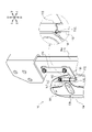
- FIG. 4 is a rear exploded perspective view showing a ramp and a support mechanism;
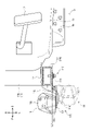
- FIG. 4 is a rear perspective view showing a ramp and support mechanism;
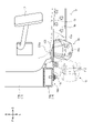
- FIG. 4 is a rear perspective view showing a state in which the fixed part (lamp) is lifted from the use position;
- FIG. 4 is a rear perspective view showing a state in which the fixed portion (lamp) is switched to the retracted position;
- FIG. 4 is an enlarged front perspective view showing the ramp and support mechanism;
- FIG. 4 is a rear exploded perspective view showing a ramp and a support mechanism;
- FIG. 4 is a rear perspective view showing a ramp and support mechanism;
- FIG. 4 is a rear perspective view showing a state in which the fixed part (lamp) is lifted from the use position;
- FIG. 4 is a rear perspective view showing a state in which the fixed portion (lamp) is switched to the retracted position;
- FIG. 4 is an enlarged front perspective view showing the lamp and support mechanism switched to the stowed position; (a) Front view showing the lamp in use position. (b) Front view showing the lamp in the retracted position.
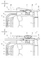
- FIG. 2 is a plan partial cross-sectional view showing a ramp and a support mechanism;
- FIG. 6 is a plan partial cross-sectional view showing a lamp and a support mechanism according to a second embodiment;
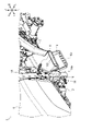
- the tractor 1 mainly includes a body frame 2, a front wheel 3, a transmission 4, a rear wheel 5, a fender 6, an engine 7, a bonnet 8, a driving operation section 9, a front safety frame 14, a rear safety frame 15, a lamp 16, and wiring 17. and a support mechanism 100 .
- the body frame 2 is arranged with its longitudinal direction facing the front-rear direction.
- a front portion of the body frame 2 is supported by a pair of left and right front wheels 3 .
- a transmission 4 is provided at the rear portion of the body frame 2 .
- a rear portion of the transmission 4 is supported by a pair of left and right rear wheels 5 .
- the rear wheel 5 is covered above and in front by a pair of left and right fenders 6 .
- An engine 7 is provided in the front-rear midway portion of the body frame 2 .
- the engine 7 is covered with a bonnet 8. Behind the engine 7, a driving operation unit 9 for the operator to operate the tractor 1 is provided.
- a step 10 a steering post 11, a clutch pedal 12, a seat 13, and the like are provided in the driving operation unit 9.
- Step 10 forms a floor for workers to board.
- An auxiliary step 10 a is provided on the side of the step 10 for assisting the operator to get on the step 10 .
- a steering post 11 is provided in front of the driving operation unit 9 .
- a steering wheel 11 a for steering the tractor 1 is provided above the steering post 11 .
- a clutch pedal 12 for operating the clutch mechanism (not shown) of the tractor 1 is provided on the front portion of the step 10 (on the left side of the steering post 11).
- the step 10 is provided with various other operation pedals (an accelerator pedal, a brake pedal, etc.).
- a seat 13 for a worker to sit on is provided in the rear portion of the operation unit 9 .
- a front safety frame 14 and a rear safety frame 15 are provided in front of and behind the operation unit 9 to protect the operator riding on the operation unit 9 .
- the front safety frame 14 is provided forward of the driving operation unit 9 .
- the front safety frame 14 includes a lower frame 14a fixed to the rear portion of the body frame 2, and an upper frame 14b provided so as to be able to swing back and forth with respect to the lower frame 14a.
- the rear safety frame 15 is provided behind the driving operation unit 9 .
- the lamp 16 is a lighting fixture that can emit light as needed.
- the lamp 16 according to the present embodiment is a lighting fixture (so-called combination lamp) that can be used for a plurality of purposes (direction indicator and side lamp).
- the lamp 16 mainly includes a lamp housing 16a and a translucent cover 16b (see FIGS. 3 and 4).
- the lamp housing 16a is a member in which a light-emitting body (such as a light bulb) that emits light is provided.
- the translucent cover 16b is a member that covers the light-emitting body provided in the lamp housing 16a. The light from the light emitter is transmitted through the translucent cover 16b and emitted to the outside. That is, the surface of the lamp 16 on which the translucent cover 16b is provided (for example, the front surface of the lamp 16 in FIG. 3A) serves as an irradiation surface for emitting light to the outside.
- Wiring 17 for supplying power and transmitting control signals is connected to the rear surface (surface opposite to the irradiation surface) of the lamp 16 (lamp housing 16a) (see FIG. 4).
- the lamps 16 are arranged on the left and right sides of the bonnet 8 in front of the driving operation unit 9 .
- the ramp 16 is provided on the front safety frame 14 (more specifically, the lower frame 14a) via a support mechanism 100. As shown in FIG.
- the power of the engine 7 is shifted by the transmission 4 and then transmitted to the front wheels 3 and the rear wheels 5 via an appropriate power transmission mechanism.
- the power of the engine 7 rotates the front wheels 3 and the rear wheels 5, and the tractor 1 travels.
- the steering wheel 11a can steer the tractor 1 by adjusting (changing) the turning angle of the pair of left and right front wheels 3, 3 according to the amount of rotation of the steering wheel 11a.
- the support mechanism 100 is for supporting the lamp 16.
- the support mechanism 100 adjusts the position of a fixed portion 130 (and thus the lamp 16) to a use position (FIGS. 3 and 9A) in which at least a part of the lamp 16 is located outside the fender 6 in the left-right direction. ) and a storage position (see FIGS. 8 and 9B) in which the lamp 16 is located inside the vehicle body relative to the fender 6 .
- 1 to 5 show a state in which the fixing portion 130 is switched to the use position.
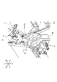
- the support mechanism 100 mainly includes a support portion 110 , a vibration isolation member 120 , a fixing portion 130 and a holding mechanism 140 .
- the support portion 110 shown in FIGS. 4 and 5 supports the lamp 16 via a fixing portion 130 which will be described later.
- the support portion 110 mainly includes a first flat plate portion 111 and an insertion portion 112 .
- the first flat plate portion 111 is a portion formed in a flat plate shape with the plate surface facing left and right.
- the first flat plate portion 111 is formed in an L-shape in a side view including a vertically extending portion and a portion projecting forward from the lower portion thereof.
- the insertion portion 112 is a portion formed in a cylindrical shape with the axial direction directed vertically. A lower end portion of the insertion portion 112 is fixed to the front lower portion of the first flat plate portion 111 . Accordingly, the insertion portion 112 is arranged to protrude upward from the front lower portion of the first flat plate portion 111 .
- the vibration isolation member 120 is a member for suppressing transmission of vibration from the vehicle body of the tractor 1 to the ramp 16 .
- the vibration isolating member 120 is formed in a rectangular plate shape.
- the vibration-isolating member 120 is made of a vibration-isolating material such as rubber.
- the fixed part 130 is a part to which the lamp 16 is fixed.
- the fixed portion 130 mainly includes a second flat plate portion 131 and a cylindrical portion 132 .
- the second flat plate portion 131 is a portion formed in a flat plate shape with its plate surface facing forward and backward.
- the second flat plate portion 131 is formed in a T-shape in a rear view including a portion extending vertically and a portion projecting laterally (to the right) from the middle portion in the vertical direction.
- a concave portion 131 a is formed in the second flat plate portion 131 .
- the recessed portion 131a is formed by recessing the upper and lower center portions of the second flat plate portion 131 toward the rear.
- the concave portion 131a is formed in a substantially elliptical shape elongated in the left-right direction.
- the cylindrical portion 132 is a portion formed in a cylindrical shape with the axial direction directed vertically.
- the cylindrical portion 132 is fixed to the right end portion of the second flat plate portion 131 .
- a notch portion 132 a is formed in the cylindrical portion 132 .
- the notch portion 132a is formed by notching the lower end portion of the cylindrical portion 132 upward.
- the notch portions 132 a are formed at four locations on the front, rear, left, and right of the lower end portion of the cylindrical portion 132 .
- the notches 132a are formed at regular intervals (every 90 degrees around the axis of the cylindrical portion 132).
- the holding mechanism 140 holds the fixed part 130 at the use position or the storage position.
- the holding mechanism 140 mainly comprises a pin 141 , a spring 142 , a plain washer 143 and a retaining ring 144 .
- the pin 141 is a cylindrical member.
- the pin 141 is provided so as to pass through the lower portion of the insertion portion 112 from side to side.
- the pin 141 is arranged such that both left and right end portions protrude left and right from the insertion portion 112 .
- the spring 142 is a member that biases the fixed portion 130 downward.
- the spring 142 is composed of a compression coil spring.
- the plain washer 143 is a member that is formed in the shape of an annular flat plate.
- the retaining ring 144 is a member that can be engaged with the insertion portion 112 .
- the first flat plate portion 111 is fixed to the outer side surface (left side surface) of the lower frame 14a of the front safety frame 14 with fasteners such as bolts.
- the support part 110 is thereby fixed to the front safety frame 14 .
- a vibration isolating member 120 is arranged between the lower frame 14 a and the first flat plate portion 111 .
- transmission of vibration from the vehicle body of the tractor 1 to the support portion 110 (and thus the ramp 16) can be suppressed.
- the insertion portion 112 is positioned forward of the front safety frame 14 (lower frame 14a).
- the second flat plate portion 131 is fixed to the rear surface of the lamp 16 (lamp housing 16a) with a fastener such as a bolt.
- the wiring 17 connected to the lamp 16 is directed toward the inside of the vehicle body (to the right) through the space between the lamp 16 and the second flat plate portion 131 (more specifically, the concave portion 131a of the second flat plate portion 131). (see FIG. 10).
- cylindrical portion 132 , the spring 142 and the flat washer 143 are sequentially inserted through the insertion portion 112 . Furthermore, above the plain washer 143 , a retaining ring 144 is locked to the upper end of the insertion portion 112 . The retaining ring 144 can prevent the cylindrical portion 132 , the spring 142 and the flat washer 143 from falling out of the insertion portion 112 .
- the cylindrical portion 132 is urged downward by the spring 142, and the notch portion 132a formed at the lower end portion of the cylindrical portion 132 is engaged with the pin 141 as shown in FIG. Therefore, rotation of the cylindrical portion 132 with respect to the insertion portion 112 is restricted, and the fixing portion 130 (lamp 16) is held at the use position.
- the fixing portion 130 is arranged such that the second flat plate portion 131 protrudes from the cylindrical portion 132 toward the outside (to the left) of the vehicle body.
- the lamp 16 fixed to the fixing portion 130 is arranged with the irradiation surface (translucent cover 16b) facing forward.
- the ramp 16 is thus attached to the front safety frame 14 via the support mechanism 100 .
- the ramp 16 By attaching the ramp 16 to the front safety frame 14 of the tractor 1 having relatively high rigidity in this way, the ramp 16 can be firmly supported.
- the ramp 16 is arranged forward of the front safety frame 14 . That is, the ramp 16 is arranged on the front side of the step 10 on which the operator gets on.
- the wiring 17 connected to the lamp 16 is arranged so as to pass through the inside (right side) of the front safety frame 14 (lower frame 14a).
- the wiring 17 is appropriately connected to a battery serving as a power source, a control board, etc. (not shown) arranged in the steering post 11 .
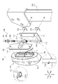
- the fixed part 130 (ramp 16) is rotated forward.
- the notch 132a different from the notch 132a with which the pin 141 was engaged in the use position matches the position of the pin 141 .
- the fixing portion 130 is lowered to engage the notch portion 132a with the pin 141.
- the fixed portion 130 (lamp 16) can be held at the retracted position.
- the fixed portion 130 (lamp 16) can be switched from the retracted position to the use position.
- the ramp 16 When using the ramp 16, such as when traveling on the road with the tractor 1, the ramp 16 is switched to the use position. As shown in FIG. 9A, when the tractor 1 is viewed from the front (front view) and the lamp 16 is switched to the use position, the left end of the lamp 16 corresponds to the outer end of the fender 6. (See auxiliary line L1 in the drawing). Since the lamp 16 can be positioned relatively outside in the use position, the light from the lamp 16 is less likely to be blocked by the bonnet 8 and the light from the lamp 16 can easily illuminate the front of the tractor 1 . Also, the lamp 16 can be easily seen from the front of the tractor 1 .
- the lamp 16 when there is no need to use the lamp 16, such as when working in a field, the lamp 16 can be switched to the retracted position.
- FIG. 9B when the tractor 1 is viewed from the front (front view), when the lamp 16 is switched to the retracted position, the lamp 16 is located at the outer edge of the fender 6 ( It is located inside (right side) of the auxiliary line L1). At the retracted position, the lamp 16 can be positioned inside the fender 6, so that the lamp 16 can be prevented from interfering with surrounding crops, obstacles, and the like. This allows the tractor 1 to work in tight spaces. In addition, damage to crops and damage to lamps 16 can be suppressed.
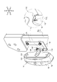
- the irradiation surface (translucent cover 16b) of the lamp 16 is arranged to face the inside (right side) of the vehicle body. This can effectively prevent the irradiation surface of the lamp 16 from being damaged. Furthermore, in this state, the second flat plate portion 131 is positioned outside (on the left side) of the lamp 16, so that the second flat plate portion 131 can protect the lamp 16 from the outside, thereby preventing the lamp 16 from being damaged. can be effectively suppressed.
- the lamp 16 when the lamp 16 is switched to the retracted position, at least a part of the lamp 16 is positioned on the outer surface of the front safety frame 14 (lower frame 14a) (see auxiliary line L2 in the figure). ) so as to be located on the inner side of the vehicle body. This effectively prevents the lamp 16 from being damaged.
- the lamp 16 rotates forward when switched from the use position to the storage position.
- the ramp 16 can be moved in a direction away from the step 10 on which the worker gets on, so that the ramp 16 interferes with the worker's work (for example, getting on and off the step 10, operating the clutch pedal 12, etc.). can be prevented from becoming
- the tractor 1 (work vehicle) according to the present embodiment is a fixing portion 130 to which the lamp 16 is fixed;
- the fixing portion 130 is supported, and the position of the fixing portion 130 is set to a use position where at least a part of the lamp 16 is positioned outside the fender 6, and a position where the lamp 16 is positioned inside the vehicle body than the fender 6.
- a support portion 110 that can be switched between a stored position and a is provided.
- the support portion 110 is The fixed portion 130 is supported so that the irradiation surface of the lamp 16 faces the inside of the vehicle body when the fixed portion 130 is switched to the retracted position.
- the fixing portion 130 is It has a second flat plate portion 131 (flat plate portion) which is formed in a flat plate shape and fixed to the surface of the lamp 16 opposite to the irradiation surface.
- the lamp 16 can be protected from the outside by the second flat plate portion 131 (fixed portion 130) in the retracted position, and damage to the lamp 16 can be effectively suppressed.
- the lamp 16 is It is arranged on the front side of the vehicle body from the step 10 on which the worker gets on,
- the support part 110 is By rotating the fixing portion 130 forward from the use position, it is switched to the storage position.
- the lamp 16 when the lamp 16 is switched to the accommodation position, the lamp 16 can be prevented from interfering with the operator by rotating it away from the step 10 (toward the front side).
- the support portion 110 is It is provided on a front safety frame 14 (safety frame) arranged on the front side of the vehicle body with respect to the step 10 . With this configuration, the lamp 16 can be firmly supported.
- the support portion 110 is The fixed portion 130 is supported so that at least a portion of the lamp 16 is located inside the vehicle body relative to the front safety frame 14 when the fixed portion 130 is switched to the retracted position. With this configuration, at least a part of the lamp 16 is located inside the vehicle body relative to the front safety frame 14 in the retracted position, so that the lamp 16 can be effectively prevented from being damaged.
- it further comprises a wiring 17 connected to the lamp 16 and arranged so as to pass through the inside of the vehicle body of the front safety frame 14 .
- the tractor 1 A holding mechanism 140 capable of holding the fixing portion 130 at the use position or the storage position is further provided.
- the lamp 16 (fixed portion 130) can be stably held at a predetermined position (use position and storage position).
- tractor 1 is one embodiment of the work vehicle according to the present invention.
- second flat plate portion 131 is an embodiment of the flat plate portion according to the present invention.
- front safety frame 14 is an embodiment of the safety frame according to the present invention.
- the support portion 110 according to the second embodiment is configured to be switched to the storage position by rotating the fixing portion 130 (the lamp 16) in the use position toward the rear.
- the irradiation surface of the lamp 16 is arranged so as to face forward (see the two-dot chain line in FIG. 11), as in the first embodiment.
- the fixing portion 130 By rotating the fixing portion 130 (the lamp 16) rearward from this state by 90 degrees, the fixing portion 130 can be switched to the retracted position. At the retracted position, the irradiation surface of the lamp 16 faces outward.
- the insertion portion 112 (the rotation of the fixing portion 130 is The dynamic fulcrum) is arranged behind the front safety frame 14, but the arrangement of each member is not limited to this and can be arbitrarily changed.
- the support part 110 is The fixed portion 130 is supported so that the irradiation surface of the lamp 16 faces the outside of the vehicle body when the fixed portion 130 is switched to the retracted position.
- the irradiation surface of the lamp 16 faces the outside of the vehicle body in the retracted position, it is effective to prevent the rear surface of the lamp 16 (the lamp housing 16a, the light emitter provided on the lamp housing 16a, etc.) from being damaged. can be suppressed to
- the support portion 110 is By rotating the fixing portion 130 rearward from the use position, it is switched to the storage position. By configuring in this way, it is possible to suppress interference with surrounding crops, obstacles, etc. by storing the fixed part 130 (lamp 16) in the rear.
- the tractor 1 was exemplified as a working vehicle, but the present invention can be applied to various other working vehicles (agricultural vehicles, construction vehicles, industrial vehicles, etc.).
- the lamp 16 is provided on the front safety frame 14, but it is also possible to provide it on another safety frame (rear safety frame 15) or other member (for example, the fender 6, etc.). is.
- the lamp 16 is arranged on the front side of the step 10, but the lamp 16 may be arranged in the same position as the step 10 in the front-rear direction, or may be arranged on the rear side of the step 10. It is also possible to For example, when the lamp 16 is provided behind the step 10 (such as the fender 6 or the rear safety frame 15), the lamp 16 is configured to rotate rearward (in the direction away from the step 10). 16 can be suppressed from becoming an obstacle for the operator.
- the arrangement (position, orientation, etc.) of the lamp 16 (fixed portion 130) in the use position and the storage position is an example, and can be changed arbitrarily.
- the angle at which the position is switched can be changed arbitrarily.
- the lamp 16 may be one in which the irradiation surface faces rearward in the use position.
- the lamp 16 has been described as being used as a direction indicator or a side lamp, but the application of the lamp 16 is not limited to this, and the present invention can be applied to the lamp 16 for various purposes. It is possible.
- the present invention can be applied to work vehicles equipped with lamps.
Landscapes
- Engineering & Computer Science (AREA)
- Mechanical Engineering (AREA)
- Lighting Device Outwards From Vehicle And Optical Signal (AREA)
- Body Structure For Vehicles (AREA)
Abstract
Description
ランプ16が固定される固定部130と、
前記固定部130を支持すると共に、当該固定部130の位置を、前記ランプ16の少なくとも一部がフェンダ6よりも車体外側に位置する使用位置と、前記ランプ16が前記フェンダ6よりも車体内側に位置する収納位置と、の間で切り換え可能な支持部110と、
を具備するものである。
このように構成することにより、ランプ16(固定部130)の位置を収納位置に切り換えることで、ランプ16が周囲の作物や障害物等に干渉するのを防止することができる。 As described above, the tractor 1 (work vehicle) according to the present embodiment is
a fixing
The fixing
is provided.
With this configuration, by switching the position of the lamp 16 (fixed portion 130) to the retracted position, it is possible to prevent the
前記固定部130を前記収納位置に切り換えた状態において、前記ランプ16の照射面が車体内側を向くように前記固定部130を支持するものである。
このように構成することにより、収納位置においてランプ16の照射面が車体内側を向くため、ランプ16(特に、照射面)が傷つくのを効果的に抑制することができる。 Further, the
The fixed
By configuring in this way, since the irradiation surface of the
平板状に形成され、前記ランプ16の前記照射面と反対側の面に対して固定される第二平板部131(平板部)を具備するものである。
このように構成することにより、収納位置において、第二平板部131(固定部130)によってランプ16を外側から保護することができ、ランプ16が傷つくのを効果的に抑制することができる。 Further, the fixing
It has a second flat plate portion 131 (flat plate portion) which is formed in a flat plate shape and fixed to the surface of the
With this configuration, the
作業者が搭乗するステップ10よりも車体前側に配置され、
前記支持部110は、
前記使用位置にある前記固定部130を前方に向かって回動させることで、前記収納位置に切り換えるものである。
このように構成することにより、ランプ16を収容位置に切り換える場合、ステップ10から離れる方向(前側)に回動させることで、ランプ16が作業者の邪魔になるのを防止することができる。 Further, the
It is arranged on the front side of the vehicle body from the
The
By rotating the fixing
With this configuration, when the
前記ステップ10よりも車体前側に配置された前部安全フレーム14(安全フレーム)に設けられるものである。
このように構成することにより、ランプ16を強固に支持することができる。 Further, the
It is provided on a front safety frame 14 (safety frame) arranged on the front side of the vehicle body with respect to the
With this configuration, the
前記固定部130を前記収納位置に切り換えた状態において、前記ランプ16の少なくとも一部が前記前部安全フレーム14よりも車体内側に位置するように前記固定部130を支持するものである。
このように構成することにより、収納位置において、ランプ16の少なくとも一部が前部安全フレーム14よりも車体内側に位置するため、ランプ16が傷つくのを効果的に抑制することができる。 Further, the
The fixed
With this configuration, at least a part of the
このように構成することにより、配線17が周囲の作物や障害物等に干渉するのを防止することができる。 Moreover, it further comprises a
By configuring in this way, it is possible to prevent the
前記固定部130を、前記使用位置又は前記収納位置に保持可能な保持機構140をさらに具備するものである。
このように構成することにより、ランプ16(固定部130)を所定の位置(使用位置及び収納位置)に安定して保持することができる。 Also, the
A
With this configuration, the lamp 16 (fixed portion 130) can be stably held at a predetermined position (use position and storage position).
また、本実施形態に係る第二平板部131は、本発明に係る平板部の一実施形態である。
また、本実施形態に係る前部安全フレーム14は、本発明に係る安全フレームの一実施形態である。 In addition, the
Further, the second
Also, the
前記固定部130を前記収納位置に切り換えた状態において、前記ランプ16の照射面が車体外側を向くように前記固定部130を支持するものである。
このように構成することにより、収納位置においてランプ16の照射面が車体外側を向くため、ランプ16の背面(ランプハウジング16aや、ランプハウジング16aに設けられた発光体等)が傷つくのを効果的に抑制することができる。 Thus, the
The fixed
With this configuration, since the irradiation surface of the
前記使用位置にある前記固定部130を後方に向かって回動させることで、前記収納位置に切り換えるものである。
このように構成することにより、固定部130(ランプ16)を後方に納めることで、周囲の作物や障害物等に干渉するのを抑制することができる。 Further, the
By rotating the fixing
By configuring in this way, it is possible to suppress interference with surrounding crops, obstacles, etc. by storing the fixed part 130 (lamp 16) in the rear.
6 フェンダ
9 ステップ
14 前部安全フレーム
16 ランプ
17 配線
100 支持機構
110 支持部
120 防振部材
130 固定部
131 第二平板部
140 保持機構 1
Claims (10)
- ランプが固定される固定部と、
前記固定部を支持すると共に、当該固定部の位置を、前記ランプの少なくとも一部がフェンダよりも車体外側に位置する使用位置と、前記ランプが前記フェンダよりも車体内側に位置する収納位置と、の間で切り換え可能な支持部と、
を具備する作業車両。 a fixing part to which the lamp is fixed;
The fixed part is supported, and the position of the fixed part is set to a use position where at least part of the lamp is positioned outside the fender of the vehicle body, and a storage position where the lamp is positioned inside the vehicle body of the fender; a support switchable between
A work vehicle equipped with - 前記支持部は、
前記固定部を前記収納位置に切り換えた状態において、前記ランプの照射面が車体内側を向くように前記固定部を支持する、
請求項1に記載の作業車両。 The support part is
supporting the fixed portion so that the irradiation surface of the lamp faces the inside of the vehicle body in a state where the fixed portion is switched to the retracted position;
The work vehicle according to claim 1. - 前記固定部は、
平板状に形成され、前記ランプの前記照射面と反対側の面に対して固定される平板部を具備する、
請求項2に記載の作業車両。 The fixed part is
A flat plate portion formed in a flat plate shape and fixed to the surface of the lamp opposite to the irradiation surface,
The work vehicle according to claim 2. - 前記ランプは、
作業者が搭乗するステップよりも車体前側に配置され、
前記支持部は、
前記使用位置にある前記固定部を前方に向かって回動させることで、前記収納位置に切り換える、
請求項1から請求項3までのいずれか一項に記載の作業車両。 The lamp is
It is placed on the front side of the vehicle body than the step where the worker gets on,
The support part is
Switching to the storage position by rotating the fixing part in the use position forward.
A work vehicle according to any one of claims 1 to 3. - 前記支持部は、
前記ステップよりも車体前側に配置された安全フレームに設けられる、
請求項4に記載の作業車両。 The support part is
Provided on a safety frame arranged on the front side of the vehicle body than the step,
The work vehicle according to claim 4. - 前記支持部は、
前記固定部を前記収納位置に切り換えた状態において、前記ランプの少なくとも一部が前記安全フレームよりも車体内側に位置するように前記固定部を支持する、
請求項5に記載の作業車両。 The support part is
supporting the fixing portion so that at least a portion of the lamp is located inside the vehicle body with respect to the safety frame when the fixing portion is switched to the retracted position;
The work vehicle according to claim 5. - 前記ランプに接続され、前記安全フレームの車体内側を通るように配置される配線をさらに具備する、
請求項5又は請求項6に記載の作業車両。 further comprising wiring connected to the lamp and arranged to pass through the inside of the vehicle body of the safety frame;
The work vehicle according to claim 5 or 6. - 前記支持部は、
前記固定部を前記収納位置に切り換えた状態において、前記ランプの照射面が車体外側を向くように前記固定部を支持する、
請求項1に記載の作業車両。 The support part is
supporting the fixed portion so that the irradiation surface of the lamp faces the outside of the vehicle body in a state where the fixed portion is switched to the retracted position;
The work vehicle according to claim 1. - 前記支持部は、
前記使用位置にある前記固定部を後方に向かって回動させることで、前記収納位置に切り換える、
請求項1に記載の作業車両。 The support part is
Switching to the storage position by rotating the fixing part in the use position toward the rear,
The work vehicle according to claim 1. - 前記固定部を、前記使用位置又は前記収納位置に保持可能な保持機構をさらに具備する、
請求項1から請求項9までのいずれか一項に記載の作業車両。 further comprising a holding mechanism capable of holding the fixing portion at the use position or the storage position;
A work vehicle according to any one of claims 1 to 9.
Priority Applications (2)
| Application Number | Priority Date | Filing Date | Title |
|---|---|---|---|
| EP22832534.6A EP4365374A1 (en) | 2021-06-28 | 2022-03-28 | Work vehicle |
| US18/544,534 US20240116435A1 (en) | 2021-06-28 | 2023-12-19 | Working vehicle |
Applications Claiming Priority (2)
| Application Number | Priority Date | Filing Date | Title |
|---|---|---|---|
| JP2021107069A JP2023005278A (en) | 2021-06-28 | 2021-06-28 | Service vehicle |
| JP2021-107069 | 2021-06-28 |
Related Child Applications (1)
| Application Number | Title | Priority Date | Filing Date |
|---|---|---|---|
| US18/544,534 Continuation US20240116435A1 (en) | 2021-06-28 | 2023-12-19 | Working vehicle |
Publications (1)
| Publication Number | Publication Date |
|---|---|
| WO2023276373A1 true WO2023276373A1 (en) | 2023-01-05 |
Family
ID=84692644
Family Applications (1)
| Application Number | Title | Priority Date | Filing Date |
|---|---|---|---|
| PCT/JP2022/015128 WO2023276373A1 (en) | 2021-06-28 | 2022-03-28 | Work vehicle |
Country Status (4)
| Country | Link |
|---|---|
| US (1) | US20240116435A1 (en) |
| EP (1) | EP4365374A1 (en) |
| JP (1) | JP2023005278A (en) |
| WO (1) | WO2023276373A1 (en) |
Citations (5)
| Publication number | Priority date | Publication date | Assignee | Title |
|---|---|---|---|---|
| JPS6150845A (en) * | 1984-08-16 | 1986-03-13 | Yanmar Diesel Engine Co Ltd | Setting structure of clearance lamps for farm tractor |
| JPS6226746U (en) * | 1985-08-02 | 1987-02-18 | ||
| JPH0325038A (en) * | 1989-06-22 | 1991-02-01 | Toyota Autom Loom Works Ltd | Head lamp for industrial vehicle |
| JP2017019454A (en) | 2015-07-14 | 2017-01-26 | 井関農機株式会社 | Work vehicle |
| JP2019026169A (en) * | 2017-08-02 | 2019-02-21 | 株式会社クボタ | Support mechanism of license plate and work vehicle having the same |
-
2021
- 2021-06-28 JP JP2021107069A patent/JP2023005278A/en active Pending
-
2022
- 2022-03-28 EP EP22832534.6A patent/EP4365374A1/en active Pending
- 2022-03-28 WO PCT/JP2022/015128 patent/WO2023276373A1/en active Application Filing
-
2023
- 2023-12-19 US US18/544,534 patent/US20240116435A1/en active Pending
Patent Citations (5)
| Publication number | Priority date | Publication date | Assignee | Title |
|---|---|---|---|---|
| JPS6150845A (en) * | 1984-08-16 | 1986-03-13 | Yanmar Diesel Engine Co Ltd | Setting structure of clearance lamps for farm tractor |
| JPS6226746U (en) * | 1985-08-02 | 1987-02-18 | ||
| JPH0325038A (en) * | 1989-06-22 | 1991-02-01 | Toyota Autom Loom Works Ltd | Head lamp for industrial vehicle |
| JP2017019454A (en) | 2015-07-14 | 2017-01-26 | 井関農機株式会社 | Work vehicle |
| JP2019026169A (en) * | 2017-08-02 | 2019-02-21 | 株式会社クボタ | Support mechanism of license plate and work vehicle having the same |
Also Published As
| Publication number | Publication date |
|---|---|
| JP2023005278A (en) | 2023-01-18 |
| US20240116435A1 (en) | 2024-04-11 |
| EP4365374A1 (en) | 2024-05-08 |
Similar Documents
| Publication | Publication Date | Title |
|---|---|---|
| JP6725259B2 (en) | cart | |
| US9487258B2 (en) | Straddled vehicle | |
| EP3106347B1 (en) | Headlight system for an off-road vehicle | |
| EP3689722B1 (en) | Combination light | |
| WO2023276373A1 (en) | Work vehicle | |
| EP3437933B1 (en) | License plate support mechanism and work vehicle equipped with license plate support mechanism | |
| US10544021B2 (en) | Industrial vehicle and lighting device | |
| EP3150431B1 (en) | Two-wheeled motor vehicle | |
| EP3574743B1 (en) | Headlight assembly for a mower | |
| US10322763B2 (en) | Head lamp device of straddle-type vehicle | |
| US20080092688A1 (en) | Traveling Operation Device and Working Vehicle | |
| WO2023027155A1 (en) | Supporting structure for light unit | |
| JP2008168888A (en) | Motorcycle | |
| JP2018034677A (en) | Tractor | |
| JP2022094436A (en) | Operation device for handlebar | |
| JP4407907B2 (en) | Transporter | |
| JP6561567B2 (en) | Work vehicle | |
| JP2022067547A (en) | Tractor | |
| JP2022187340A (en) | Vehicular lighting fixture | |
| JP4330965B2 (en) | Traveling vehicle | |
| WO2017099035A1 (en) | Headlight for vehicle | |
| JP2004161270A (en) | Working vehicle light system | |
| JP2011126351A (en) | Working vehicle | |
| JP2006073238A (en) | Blinker lamp for working vehicle | |
| JPH10278666A (en) | Illumination device of vehicle |
Legal Events
| Date | Code | Title | Description |
|---|---|---|---|
| 121 | Ep: the epo has been informed by wipo that ep was designated in this application |
Ref document number: 22832534 Country of ref document: EP Kind code of ref document: A1 |
|
| WWE | Wipo information: entry into national phase |
Ref document number: 2301008604 Country of ref document: TH |
|
| WWE | Wipo information: entry into national phase |
Ref document number: 2022832534 Country of ref document: EP |
|
| NENP | Non-entry into the national phase |
Ref country code: DE |
|
| ENP | Entry into the national phase |
Ref document number: 2022832534 Country of ref document: EP Effective date: 20240129 |