WO2023276233A1 - 流体荷役装置の緊急離脱機構 - Google Patents
流体荷役装置の緊急離脱機構 Download PDFInfo
- Publication number
- WO2023276233A1 WO2023276233A1 PCT/JP2022/004855 JP2022004855W WO2023276233A1 WO 2023276233 A1 WO2023276233 A1 WO 2023276233A1 JP 2022004855 W JP2022004855 W JP 2022004855W WO 2023276233 A1 WO2023276233 A1 WO 2023276233A1
- Authority
- WO
- WIPO (PCT)
- Prior art keywords
- valve
- pair
- portions
- fluid
- release mechanism
- Prior art date
- Legal status (The legal status is an assumption and is not a legal conclusion. Google has not performed a legal analysis and makes no representation as to the accuracy of the status listed.)
- Ceased
Links
Images

Classifications
-
- F—MECHANICAL ENGINEERING; LIGHTING; HEATING; WEAPONS; BLASTING
- F16—ENGINEERING ELEMENTS AND UNITS; GENERAL MEASURES FOR PRODUCING AND MAINTAINING EFFECTIVE FUNCTIONING OF MACHINES OR INSTALLATIONS; THERMAL INSULATION IN GENERAL
- F16K—VALVES; TAPS; COCKS; ACTUATING-FLOATS; DEVICES FOR VENTING OR AERATING
- F16K31/00—Actuating devices; Operating means; Releasing devices
- F16K31/12—Actuating devices; Operating means; Releasing devices actuated by fluid
- F16K31/122—Actuating devices; Operating means; Releasing devices actuated by fluid the fluid acting on a piston
-
- F—MECHANICAL ENGINEERING; LIGHTING; HEATING; WEAPONS; BLASTING
- F16—ENGINEERING ELEMENTS AND UNITS; GENERAL MEASURES FOR PRODUCING AND MAINTAINING EFFECTIVE FUNCTIONING OF MACHINES OR INSTALLATIONS; THERMAL INSULATION IN GENERAL
- F16L—PIPES; JOINTS OR FITTINGS FOR PIPES; SUPPORTS FOR PIPES, CABLES OR PROTECTIVE TUBING; MEANS FOR THERMAL INSULATION IN GENERAL
- F16L37/00—Couplings of the quick-acting type
- F16L37/28—Couplings of the quick-acting type with fluid cut-off means
- F16L37/30—Couplings of the quick-acting type with fluid cut-off means with fluid cut-off means in each of two pipe-end fittings
- F16L37/36—Couplings of the quick-acting type with fluid cut-off means with fluid cut-off means in each of two pipe-end fittings with two lift valves being actuated to initiate the flow through the coupling after the two coupling parts are locked against withdrawal
-
- B—PERFORMING OPERATIONS; TRANSPORTING
- B63—SHIPS OR OTHER WATERBORNE VESSELS; RELATED EQUIPMENT
- B63B—SHIPS OR OTHER WATERBORNE VESSELS; EQUIPMENT FOR SHIPPING
- B63B27/00—Arrangement of ship-based loading or unloading equipment for cargo or passengers
- B63B27/24—Arrangement of ship-based loading or unloading equipment for cargo or passengers of pipe-lines
-
- B—PERFORMING OPERATIONS; TRANSPORTING
- B67—OPENING, CLOSING OR CLEANING BOTTLES, JARS OR SIMILAR CONTAINERS; LIQUID HANDLING
- B67D—DISPENSING, DELIVERING OR TRANSFERRING LIQUIDS, NOT OTHERWISE PROVIDED FOR
- B67D9/00—Apparatus or devices for transferring liquids when loading or unloading ships
-
- F—MECHANICAL ENGINEERING; LIGHTING; HEATING; WEAPONS; BLASTING
- F16—ENGINEERING ELEMENTS AND UNITS; GENERAL MEASURES FOR PRODUCING AND MAINTAINING EFFECTIVE FUNCTIONING OF MACHINES OR INSTALLATIONS; THERMAL INSULATION IN GENERAL
- F16K—VALVES; TAPS; COCKS; ACTUATING-FLOATS; DEVICES FOR VENTING OR AERATING
- F16K1/00—Lift valves or globe valves, i.e. cut-off apparatus with closure members having at least a component of their opening and closing motion perpendicular to the closing faces
- F16K1/32—Details
- F16K1/34—Cutting-off parts, e.g. valve members, seats
- F16K1/44—Details of seats or valve members of double-seat valves
-
- F—MECHANICAL ENGINEERING; LIGHTING; HEATING; WEAPONS; BLASTING
- F16—ENGINEERING ELEMENTS AND UNITS; GENERAL MEASURES FOR PRODUCING AND MAINTAINING EFFECTIVE FUNCTIONING OF MACHINES OR INSTALLATIONS; THERMAL INSULATION IN GENERAL
- F16K—VALVES; TAPS; COCKS; ACTUATING-FLOATS; DEVICES FOR VENTING OR AERATING
- F16K49/00—Means in or on valves for heating or cooling
-
- F—MECHANICAL ENGINEERING; LIGHTING; HEATING; WEAPONS; BLASTING
- F16—ENGINEERING ELEMENTS AND UNITS; GENERAL MEASURES FOR PRODUCING AND MAINTAINING EFFECTIVE FUNCTIONING OF MACHINES OR INSTALLATIONS; THERMAL INSULATION IN GENERAL
- F16L—PIPES; JOINTS OR FITTINGS FOR PIPES; SUPPORTS FOR PIPES, CABLES OR PROTECTIVE TUBING; MEANS FOR THERMAL INSULATION IN GENERAL
- F16L23/00—Flanged joints
- F16L23/02—Flanged joints the flanges being connected by members tensioned axially
- F16L23/036—Flanged joints the flanges being connected by members tensioned axially characterised by the tensioning members, e.g. specially adapted bolts or C-clamps
-
- F—MECHANICAL ENGINEERING; LIGHTING; HEATING; WEAPONS; BLASTING
- F16—ENGINEERING ELEMENTS AND UNITS; GENERAL MEASURES FOR PRODUCING AND MAINTAINING EFFECTIVE FUNCTIONING OF MACHINES OR INSTALLATIONS; THERMAL INSULATION IN GENERAL
- F16L—PIPES; JOINTS OR FITTINGS FOR PIPES; SUPPORTS FOR PIPES, CABLES OR PROTECTIVE TUBING; MEANS FOR THERMAL INSULATION IN GENERAL
- F16L23/00—Flanged joints
- F16L23/04—Flanged joints the flanges being connected by members tensioned in the radial plane
-
- F—MECHANICAL ENGINEERING; LIGHTING; HEATING; WEAPONS; BLASTING
- F16—ENGINEERING ELEMENTS AND UNITS; GENERAL MEASURES FOR PRODUCING AND MAINTAINING EFFECTIVE FUNCTIONING OF MACHINES OR INSTALLATIONS; THERMAL INSULATION IN GENERAL
- F16L—PIPES; JOINTS OR FITTINGS FOR PIPES; SUPPORTS FOR PIPES, CABLES OR PROTECTIVE TUBING; MEANS FOR THERMAL INSULATION IN GENERAL
- F16L43/00—Bends; Siphons
- F16L43/02—Bends; Siphons adapted to make use of special securing means
-
- Y—GENERAL TAGGING OF NEW TECHNOLOGICAL DEVELOPMENTS; GENERAL TAGGING OF CROSS-SECTIONAL TECHNOLOGIES SPANNING OVER SEVERAL SECTIONS OF THE IPC; TECHNICAL SUBJECTS COVERED BY FORMER USPC CROSS-REFERENCE ART COLLECTIONS [XRACs] AND DIGESTS
- Y10—TECHNICAL SUBJECTS COVERED BY FORMER USPC
- Y10T—TECHNICAL SUBJECTS COVERED BY FORMER US CLASSIFICATION
- Y10T137/00—Fluid handling
- Y10T137/6416—With heating or cooling of the system
-
- Y—GENERAL TAGGING OF NEW TECHNOLOGICAL DEVELOPMENTS; GENERAL TAGGING OF CROSS-SECTIONAL TECHNOLOGIES SPANNING OVER SEVERAL SECTIONS OF THE IPC; TECHNICAL SUBJECTS COVERED BY FORMER USPC CROSS-REFERENCE ART COLLECTIONS [XRACs] AND DIGESTS
- Y10—TECHNICAL SUBJECTS COVERED BY FORMER USPC
- Y10T—TECHNICAL SUBJECTS COVERED BY FORMER US CLASSIFICATION
- Y10T137/00—Fluid handling
- Y10T137/6851—With casing, support, protector or static constructional installations
- Y10T137/7036—Jacketed
-
- Y—GENERAL TAGGING OF NEW TECHNOLOGICAL DEVELOPMENTS; GENERAL TAGGING OF CROSS-SECTIONAL TECHNOLOGIES SPANNING OVER SEVERAL SECTIONS OF THE IPC; TECHNICAL SUBJECTS COVERED BY FORMER USPC CROSS-REFERENCE ART COLLECTIONS [XRACs] AND DIGESTS
- Y10—TECHNICAL SUBJECTS COVERED BY FORMER USPC
- Y10T—TECHNICAL SUBJECTS COVERED BY FORMER US CLASSIFICATION
- Y10T137/00—Fluid handling
- Y10T137/8593—Systems
- Y10T137/87917—Flow path with serial valves and/or closures
- Y10T137/87925—Separable flow path section, valve or closure in each
Definitions
- the present invention relates to an emergency release mechanism for a fluid handling device that transports fluid.
- Fluid handling equipment that transports fluids such as liquefied gas from land facilities to tanks on ships is in practical use.
- the fluid handling system has an emergency release mechanism to disconnect the joint from the movable piping in an emergency.
- an emergency detachment mechanism such as that disclosed in Patent Document 1 is known.
- the valve body is biased by a spring member. Then, the biased valve body is seated on the valve seat and closes the flow path of the pipe when it is separated.
- Fluid handling equipment is required to transport a larger flow rate of fluid. Therefore, it is desired to increase the diameter of piping for transporting fluids.
- the emergency detachment mechanism of Patent Document 1 if the diameter of the pipe is large, there is a possibility that the spring member cannot obtain a sufficient urging force to close the flow path.
- the object of the present invention is to provide an emergency release mechanism for a fluid handling apparatus that can close the flow path even if the diameter of the piping is increased.
- An emergency release mechanism for a fluid handling device is an emergency release mechanism for a fluid handling device that transports fluid, and is a vacuum double structure in which a flow path for transporting fluid is formed and open ends are placed against each other.
- a detachable connecting member that connects the pair of pipes; and a pair of shutoff valves that are provided corresponding to each of the pair of pipes and block the flow path.
- Each of the pair of piping sections has a valve seat formed in the flow path, and the cutoff valve includes a valve element that is seated on the valve seat of the corresponding piping section to close the flow path. and a linear drive device for moving the valve body along the flow path to seat it on the valve seat.
- the valve body can be moved with a large driving force by using the direct drive device. As a result, even when the diameter of the pipe portion is increased, the valve body can be moved against the fluid to close the flow path of the pipe portion. That is, the valve body can be closed even if the diameter of the pipe is increased.
- the flow path can be closed even if the pipe has a large diameter.
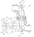
- FIG. 2 is a cross-sectional view showing an emergency release mechanism of the fluid cargo handling device according to the first embodiment of the present invention
- FIG. 2 is a cross-sectional view showing a state in which the flow path is closed with respect to the emergency detachment mechanism of FIG. 1
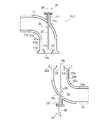
- FIG. 3 is a cross-sectional view showing a state in which a pair of pipe portions are separated from each other with respect to the emergency detachment mechanism of FIG. 2 ;
- the emergency release mechanism 2 of the fluid cargo handling device 1 of the embodiment according to the present invention will be described below with reference to the aforementioned drawings. It should be noted that the concept of direction used in the following description is used for convenience of explanation, and does not limit the orientation of the configuration of the invention to that direction. Moreover, the fluid cargo handling apparatus 1 described below is merely an embodiment of the present invention. Therefore, the present invention is not limited to the embodiments, and additions, deletions, and modifications can be made without departing from the spirit of the invention.
- a fluid cargo handling apparatus 1 shown in FIG. 1 is an apparatus for transporting fluid between a vessel (eg, tanker) having tanks and a land facility (eg, land-side tank).
- the transported fluid is liquefied hydrogen.
- the fluid to be transported is not limited to liquefied hydrogen, and may be liquefied helium, LNG, or the like.
- the fluid is not limited to liquid, and may be gas such as hydrogen gas.
- the fluid cargo handling device 1 has a movable pipe (not shown), an emergency release mechanism 2, and a joint (not shown).
- the movable piping is connected to the onshore facility and allows fluid to flow therein.
- the joint is provided at the tip of the movable pipe via the emergency release mechanism 2 .
- the joint can be connected to the tanker.
- the joint then connects to the tanker to allow fluid transport between the onshore facility and the tanker via movable piping.
- the movable pipe has, for example, a column and an arm.
- the struts are provided on land facilities.
- the arm is provided with a joint via an emergency release mechanism 2 at the tip. The arm can then pivot around the support and tilt up and down. This allows the joint to be moved to various positions.
- the emergency release mechanism 2 makes it possible to disconnect the joint from the movable pipe. More specifically, the emergency release mechanism 2 includes a pair of pipe sections 11 and 12, a connecting member 13, and a pair of cutoff valves 14 and 15. As shown in FIG.
- Each of the pair of pipe sections 11 and 12 is connected to the arm and joint of the movable pipe, respectively. More specifically, one pipe section 11 is connected to the arm of the movable pipe, and the other pipe section 12 is connected to the joint. Further, the pair of pipe sections 11 and 12 are respectively formed with channels 11a and 12a for transporting fluid therein.
- the flow paths 11a and 12a have opening ends 11b and 12b that are opened at one ends of the pair of pipe portions 11 and 12, respectively.
- the pair of pipe portions 11 and 12 are arranged so that the opening ends 11b and 12b of the pipe portions 11b and 12b face each other. Thereby, the pair of pipe portions 11 and 12 are connected to each other so as to connect the flow paths 11a and 12a. Also, the pair of pipe sections 11 and 12 can be separated from each other at their respective open ends 11b and 12b.
- the pair of pipe portions 11 and 12 are L-shaped elbow pipe joints, and have elbow portions 11c and 12c and flange portions 11d and 12d, respectively. More specifically, in the pair of pipe portions 11 and 12, the portions on the side of the opening ends 11b and 12b, i.e., the one end portions are formed linearly so as to extend along the axis L1. Elbow portions 11 c and 12 c are formed in intermediate portions of pipe portions 11 and 12 . In this embodiment, the elbow portions 11c and 12c are formed so as to be connected to the one end portion described above. The pipe portions 11 and 12 are bent at a predetermined angle by the elbow portions 11c and 12c. Although the predetermined angle is 90 degrees in this embodiment, it may be 45 degrees or 180 degrees, and the angle is not limited.
- the flange portions 11d and 12d are formed so as to protrude radially outward from the opening ends 11b and 12b of the pipe portions 11 and 12 .
- the flange portions 11d and 12d are formed on the outer peripheral surfaces of the pipe portions 11 and 12 over the entire circumferential direction.
- the pair of pipe portions 11 and 12 are arranged so that the flange portions 11d and 12d are butted against each other.
- the pair of pipe sections 11 and 12 are arranged as follows in the present embodiment in a state where they face each other.
- the portion of one piping portion 11 closer to the arm than the elbow portion 11c and the portion of the other piping portion 12 closer to the joint than the elbow portion 12c intersect each other in the axial direction where the axis L1 extends. It is arranged so as to be parallel to the direction (perpendicular direction in this embodiment fluid).
- the pair of piping parts 11 and 12 are vacuum double structure piping members. More specifically, the pair of pipe sections 11 and 12 has inner cylinder portions 21a and 22a and outer cylinder portions 21b and 22b. In the inner cylinder portions 21a, 22a, inner holes, which are the flow paths 11a, 12a, are formed along the axes of the inner cylinder portions 21a, 22a. The outer cylinder portions 21b and 22b are placed on the inner cylinder portions 21a and 22a with a space therebetween in the radial direction. Both ends are closed between the inner cylinder portions 21a, 22a and the outer cylinder portions 21b, 22b.
- vacuum layers 21c and 22c are formed between the inner cylinder portions 21a and 22a and the outer cylinder portions 21b and 22b. Heat input to the flow paths 11a and 12a in the piping portions 11 and 12 is suppressed by the vacuum layers 21c and 22c. That is, the temperature of the fluid flowing through the flow paths 11a and 12a can be maintained, and for example, the temperature of the liquid can be maintained at an extremely low temperature during transportation of the fluid.
- each of the pair of pipe sections 11 and 12 has valve seats 11e and 12e.
- Valve seats 11e and 12e are formed in flow paths 11a and 12a, respectively. More specifically, the valve seats 11e and 12e are formed on the opening ends 11b and 12b of the flow paths 11a and 12a. Although the valve seats 11e and 12e are formed so as to be connected to the opening ends 11b and 12b in the present embodiment, they are formed away from the opening ends 11b and 12b toward the inside in the axial direction of the piping portions 11 and 12. good too.
- the valve seats 11e and 12e are formed by radially inwardly projecting the inner cylindrical portions 21a and 22a along the entire circumferential direction.
- the valve seats 11e and 12e are tapered (for example, tapered or stepped) toward the open ends 11b and 12b. In this embodiment, the valve seats 11e and 12e are tapered.
- the connecting member 13 is a member that connects the pair of pipe portions 11 and 12 . More specifically, the connecting member 13 connects the butted flanges 11d and 12d. Also, the connecting member 13 can be removed from the pair of pipe portions 11 and 12 . The pair of pipe portions 11 and 12 can be separated from each other by removing the connecting member 13 .
- the connecting member 13 is a clamper. That is, the connecting member 13 connects the pair of pipe portions 11 and 12 by sandwiching the flange portions 11d and 12d. Further, the connecting member 13, which is a clamper, can be removed from the pair of pipe portions 11 and 12 by releasing the clamping of the flange portions 11d and 12d by opening. Note that the connecting member 13 is not limited to a clamper, and may be a fastening member such as a bolt. That is, it is sufficient that the pair of pipe portions 11 and 12 can be connected and detached.
- shutoff valve A pair of shutoff valves 14 and 15 are provided in the corresponding piping portions 11 and 12, respectively. Each of the pair of shutoff valves 14 and 15 shuts off the flow paths 11a and 12a of the corresponding piping portions 11 and 12, respectively. More specifically, each of the pair of shutoff valves 14, 15 has a valve element 23, 24 and a linear drive device 25, 26, respectively.
- valve bodies 23 and 24 are seated on the valve seats 11e and 12e of the corresponding piping portions 11 and 12, respectively.
- the valve bodies 23 and 24 close the flow paths 11a and 12a by sitting on the valve seats 11e and 12e.
- the valve bodies 23 and 24 are arranged in the flow paths 11a and 12a. Then, the valve bodies 23 and 24 move from the closed position to the open position along the flow paths 11a and 12a.
- the closed position is the position where the valve bodies 23 and 24 are seated on the valve seats 11e and 12e
- the open position is the position where the valve bodies 23 and 24 are separated from the valve seats 11e and 12e.
- the valve bodies 23 and 24 are arranged at one end side portions (that is, linear portions) of the pair of pipe portions 11 and 12 in this embodiment.
- Flow paths 11a and 12a extend in the axial direction at one end portions of the pair of pipe portions 11 and 12 .
- the valve bodies 23 and 24 are configured to be movable along the axis L1 along the flow paths 11a and 12a.
- the valve bodies 23 and 24 do not necessarily have to be configured to be movable along the axis L1.
- the valve bodies 23 and 24 may move along a direction inclined by a predetermined angle (for example, 30 degrees or less) with respect to the axis L1. Such a case is also synonymous with movement of the valve bodies 23 and 24 along the flow paths 11a and 12a.
- valve bodies 23 and 24 are tapered (for example, truncated cone-shaped or step-shaped) toward the distal end side in the same manner as the valve seats 11e and 12e.
- the valve bodies 23 and 24 are tapered like the valve seats 11e and 12e.
- the valve bodies 23 and 24 are then seated on the valve seats 11e and 12e.
- the channels 11a and 12a are closed.
- the outer diameters of the valve bodies 23 and 24 are smaller than those of the flow paths 11a and 12a. Therefore, when the valve bodies 23 and 24 are in the open position, the fluid flows between the flow path 11a of the piping section 11 on one side and the flow path 12a of the piping section 12 on the other side.
- valve bodies 23 and 24 are separated from each other in the axial direction while seated on the valve seats 11e and 12e as shown in FIG. More specifically, the valve bodies 23 and 24 are spaced inside the pipe sections 11 and 12 from the open ends 11b and 12b.
- the end surfaces of the valve bodies 23 and 24 on the side of the opening ends 11b and 12b are separated from the opening ends 11b and 12b to the inside of the piping portions 11 and 12 by predetermined distances A1 and A2.
- the valve bodies 23 and 24 do not contact each other when the pair of pipe portions 11 and 12 are connected. Therefore, the valve bodies 23 and 24 can be seated on the valve seats 11e and 12e while the pair of pipe portions 11 and 12 are connected.
- the valve bodies 23 and 24 can close the flow paths 11a and 12a before the pair of pipe portions 11 and 12 are separated.
- the valve bodies 23 and 24 are positioned inside the pipe parts 11 and 12, a sealed space 31 is formed between them while the valve bodies 23 and 24 are seated. Therefore, the predetermined distances A1 and A2 are set so that the volume of the closed space 31 is equal to or less than the predetermined volume.
- the predetermined volume is 50 liters or less, preferably 20 liters or less.
- the predetermined volume is not limited to the volume described above.
- the direct drive devices 25, 26 move the corresponding valve bodies 23, 24 along the flow paths 11a, 12a to seat them on the valve seats 11e, 12e. More specifically, the linear drives 25, 26 linearly move the valve bodies 23, 24 along the flow paths 11a, 12a between the closed position and the open position. More specifically, each of the linear drives 25, 26 has valve shafts 27, 28 and drive portions 29, 30, respectively.
- valve shafts 27,28 are connected to the valve bodies 23,24.
- the valve shafts 27, 28 extend in a predetermined direction. More specifically, the valve shafts 27 and 28 are long rod-shaped members extending in a predetermined direction.
- Valve bodies 23 and 24 are integrally provided at one end of the valve shafts 27 and 28 in a predetermined direction.
- the valve shafts 27 and 28 are provided on the valve bodies 23 and 24 so that their axes are aligned with each other.
- the valve shafts 27 and 28 are arranged along the axis L1 along which the one end portions of the pipe portions 11 and 12 extend in this embodiment. That is, the predetermined direction coincides with the axial direction in this embodiment. Note that the predetermined direction does not necessarily have to match the axial direction.
- valve shafts 27 and 28 pass through the corresponding piping portions 11 and 12 so as to be slidable in the axial direction. More specifically, valve shafts 27 and 28 pass through elbow portions 11c and 12c of corresponding piping portions 11 and 12, respectively.
- the valve shafts 27 and 28 are provided on the elbow portions 11c and 12c of the piping portions 11 and 12 so as to be slidable in the axial direction. More specifically, the valve stems 27, 28 extend from the valve bodies 23, 24 along the axis L1 to the opposite sides of the open ends 11b, 12b. Therefore, the valve shafts 27 and 28 are outer portions having a large radius of curvature in the elbow portions 11c and 12c and pass through the extension line of the axis L1.
- valve shafts 27 and 28 move the valve bodies 23 and 24 between the open position and the closed position by sliding the elbow portions 11c and 12c in the axial direction.
- the valve stems 27 and 28 slidably pass through the elbow portions 11c and 12c in a sealed state in this embodiment.
- the drive units 29 and 30 axially move the corresponding valve bodies 23 and 24 via the valve shafts 27 and 28, respectively. More specifically, the drive units 29, 30 move the corresponding valve bodies 23, 24 between the open position and the closed position via the valve stems 27, 28. As shown in FIG. More specifically, the driving portions 29 and 30 are connected to the other ends in a predetermined direction (the other ends in the axial direction in this embodiment) of the corresponding valve shafts 27 and 28 . The drive units 29 and 30 linearly move the valve shafts 27 and 28 in the axial direction. That is, the drive units 29 and 30 reciprocate the valve shafts 27 and 28 along the axial direction.
- the drive units 29 and 30 are configured including hydraulic cylinders in this embodiment.
- Drive units 29 and 30 including hydraulic cylinders are connected to a hydraulic circuit (not shown).
- the hydraulic circuit is controlled by a control device (not shown), and supplies and discharges hydraulic oil to and from the drive units 29 and 30 according to control signals from the control device.
- the drive units 29 and 30 move the valve shafts 27 and 28 in the axial direction by supplying and discharging hydraulic oil through the hydraulic circuit. This causes the valve bodies 23, 24 to move between the open position and the closed position.
- the drive units 29 and 30 are not necessarily limited to hydraulic cylinders, and may include, for example, an electric motor and a linear motion mechanism (ball screw mechanism, rack and pinion mechanism, etc.). Anything that can be driven linearly may be used.
- the drive units 29 and 30 are electric motors, the drive units 29 and 30 move the valve shafts 27 and 28 in one and the other axial direction in response to a drive signal from the control device.
- the drive portions 29 and 30 are provided on the elbow portions 11c and 12c of the corresponding piping portions 11 and 12, respectively. That is, the driving portions 29 and 30 are provided outside the pipe portions 11 and 12 . More specifically, mounting portions 11f and 12f are formed on the outer peripheral surfaces of the elbow portions 11c and 12c. The drive portions 29 and 30 are attached to the elbow portions 11c and 12c via attachment portions 11f and 12f. In this embodiment, the valve shafts 27 and 28 pass through the elbow portions 11c and 12c, and the other axial ends of the valve shafts 27 and 28 reach the mounting portions 11f and 12f. The drive portions 29 and 30 are connected to the other ends of the valve shafts 27 and 28 at the mounting portions 11f and 12f.
- the valve bodies 23, 24 are separated from the valve seats 11e, 12e (see FIG. 1) except in an emergency in which there is a possibility that the land facility and the ship are separated by a set distance or more. Thereby, the fluid can be transported via the fluid handling apparatus 1 between the land facility and the tanker.
- the emergency detachment mechanism 2 disconnects one piping section 11 from the other piping section 12 in an emergency, thereby disconnecting the tanker from the land facility. More specifically, in the emergency detachment mechanism 2, in an emergency, for example, a control signal is output from the control device to the hydraulic circuit. As a result, hydraulic oil is supplied to and discharged from the drive units 29 and 30 . As a result, the drive units 29 and 30 move the valve bodies 23 and 24 to the closed position via the valve shafts 27 and 28, respectively. Then, the channels 11a and 12a are closed (see FIG. 2). By removing the connecting member 13 from the flange portions 11d and 12d, the pipe portion 12 can be separated from the pipe portion 11 (see FIG. 3). In other words, one pipe portion 11 can be disconnected from the other pipe portion 12 while the two flow paths 11a and 12a are closed. This allows the tanker to be disconnected from the onshore facility in an emergency while reducing the flow rate of leaking fluid.
- the use of the linear drive devices 25 and 26 allows the valve bodies 23 and 24 to be moved with a large driving force. As a result, even when the pipe portions 11 and 12 have a large diameter, the valve bodies 23 and 24 can be moved against the fluid to close the flow paths 11a and 12a of the pipe portions 11 and 12. FIG. That is, the pipe diameter is increased and the valve bodies 23 and 24 can be closed.
- the valve bodies 23 and 24 can be seated on the valve seats 11e and 12e with the valve bodies 23 and 24 separated from each other. 12a can be closed. Therefore, the flow paths 11 a and 12 a can be closed before the connecting member 13 is removed from the pair of pipe portions 11 and 12 . As a result, the flow rate of fluid leaking from the flow paths 11a and 12a when the pair of pipe portions 11 and 12 are separated from each other can be suppressed. More specifically, the flow rate of the fluid leaking from the flow paths 11 a and 12 a can be suppressed to the volume of the closed space 31 . In addition, since the volume of the sealed space 31 can also be set by the predetermined distances A1 and A2, it is possible to suppress leakage of fluid at an undesired flow rate.
- valve shafts 27 and 28 pass through the elbow portions 11c and 12c, and the driving portions 29 and 30 are provided on the elbow portions 11c and 12c. Therefore, the shorter valve stems 27, 28 can be protruded from the piping portions 11, 12, so that the length of the valve stems 27, 28 can be reduced. As a result, the weight of the valve shafts 27 and 28 can be reduced, so that the size of the driving portions 29 and 30 can be reduced. Further, by suppressing the length of the valve shafts 27, 28, it is possible to suppress axial deviation of the valve shafts 27, 28.
- the emergency detachment mechanism 2 since hydraulic cylinders are used for the driving parts 29 and 30, the emergency detachment mechanism 2 can be used more safely. Furthermore, since the driving parts 29 and 30 are exposed to the outside air, it is possible to prevent the temperature of the hydraulic oil from lowering in order to move the driving parts 29 and 30 when a cryogenic fluid such as liquefied hydrogen is transported. Thereby, the viscosity of hydraulic oil can be ensured.
- the piping portions 11 and 12 are formed in an L shape, but they may be in a straight shape, for example, and the shape does not matter.
- the valve shafts 27 and 28 extend in a direction that intersects the axis of the pipe portion (the inclination with respect to the axis is 30 degrees or less), and move the valve bodies 23 and 24 in the direction that intersects.
- the valve seat is also formed to be inclined in a direction intersecting with the axis of the pipe portion.
- the valve bodies 23 and 24 are both seated and are spaced axially inward of the pipe portions 11 and 12 from the opening ends 11b and 12b. good too. That is, only one of the two valve bodies 23 and 24 may be separated from the opening ends 11b and 12b inward in the axial direction of the pipe portions 11 and 12, and the two valve bodies 23 and 24 are seated against each other. They can be arranged in any way as long as they are separated. Further, in the emergency detachment mechanism 2, it is not always necessary to output a signal from the control device to the hydraulic circuit in an emergency. For example, the emergency release mechanism 2 may be configured such that the valve bodies 23, 24 are moved by manually actuating the hydraulic circuit.
- the fluid handling apparatus 1 transports the fluid between the land facility and the ship, but the objects to be transported are not limited to between the land facility and the tanker.
- the fluid handling apparatus 1 may transport fluid between ships or between a land facility and a vehicle, regardless of the object to which the fluid is transported.
- the ship is not limited to a tanker, and may be a fuel ship that uses fluid as fuel.
Landscapes
- Engineering & Computer Science (AREA)
- General Engineering & Computer Science (AREA)
- Mechanical Engineering (AREA)
- Chemical & Material Sciences (AREA)
- Combustion & Propulsion (AREA)
- Ocean & Marine Engineering (AREA)
- Quick-Acting Or Multi-Walled Pipe Joints (AREA)
- Lift Valve (AREA)
- Loading And Unloading Of Fuel Tanks Or Ships (AREA)
- Fluid-Driven Valves (AREA)
Abstract
Description
図1に示す流体荷役装置1は、タンクを備える船(例えば、タンカー)と陸上施設(例えば、陸側タンク)との間で流体を輸送する装置である。本実施形態では、輸送される流体は、液化水素である。但し、輸送される流体は、液化水素に限定されず、液化ヘリウムやLNG等であってもよい。また、流体は、液体に限定されず、水素ガス等の気体であってもよい。そして、流体荷役装置1は、可動配管(図示せず)と、緊急離脱機構2と、ジョイント(図示せず)を有している。可動配管は、陸上施設に接続されており、その中に流体を流すことができる。ジョイントは、緊急離脱機構2を介して可動配管の先端部に設けられている。ジョイントは、タンカーに接続することができる。そして、ジョイントは、タンカーに接続することによって可動配管を介して陸上施設とタンカーとの間における流体の輸送を可能にする。また、可動配管は、例えば支柱及びアームを有している。支柱は、陸上施設に設けられている。アームは、先端部に緊急離脱機構2を介してジョイントが設けられている。そして、アームは、支柱を中心に旋回したり、また上下に傾倒したりすることができる。これにより、ジョイントを様々な位置に移動させることができる。
緊急離脱機構2は、可動配管からジョイントを切り離すことを可能にする。更に詳細に説明すると、緊急離脱機構2は、一対の配管部11,12と、連結部材13と、一対の遮断弁14,15とを備えている。
一対の配管部11,12の各々は、可動配管のアーム及びジョイントに夫々接続されている。より詳細に説明すると、一方の配管部11は、可動配管のアームに接続され、また他方の配管部12は、ジョイントに接続されている。また、一対の配管部11,12は、その中に流体を輸送する流路11a,12aが夫々形成されている。流路11a,12aは、一対の配管部11,12の一端にて開口する開口端11b,12bを有している。そして、一対の配管部11,12は、各々の開口端11b,12b同士を突き合わせるように配置される。これにより、一対の配管部11,12は、流路11a,12aを繋ぐように互いに接続される。また、一対の配管部11,12は、各々の開口端11b,12bで互いに引き離すことができる。
連結部材13は、一対の配管部11,12を連結する部材である。更に詳細に説明すると、連結部材13は、突き合わされるフランジ部11d,12dを連結する。また、連結部材13は、一対の配管部11,12から取り外すことができる。そして、一対の配管部11,12は、連結部材13が取り外されることによって互いに引き離すことができる。本実施形態において、連結部材13は、クランパーである。即ち、連結部材13は、フランジ部11d,12dを挟持することによって一対の配管部11,12を連結する。また、クランパーである連結部材13は、開くことによってフランジ部11d,12dに対する挟持を解除し、一対の配管部11,12から取り外すことができる。なお、連結部材13は、クランパーに限定されず、ボルト等の締結部材であってもよい。即ち、一対の配管部11,12を連結し、また取り外すことができればよい。
一対の遮断弁14,15は、対応する配管部11,12に夫々設けられている。そして、一対の遮断弁14,15の各々は、対応する配管部11,12の流路11a,12aを遮断する。更に詳細に説明すると、一対の遮断弁14,15の各々は、弁体23,24と、直動駆動装置25,26とを夫々有している。
弁体23,24は、対応する配管部11,12の弁座11e,12eに着座する。そして、弁体23,24は、弁座11e,12eに着座することによって流路11a,12aを閉じる。また、弁体23,24は、流路11a,12aに配置されている。そして、弁体23,24は、流路11a,12aに沿って閉位置から開位置に移動する。閉位置は、弁体23,24が弁座11e,12eに着座する位置であり、開位置は、弁体23,24が弁座11e,12eから離れた位置である。
直動駆動装置25,26は、対応する弁体23,24を流路11a,12aに沿って動かして弁座11e,12eに着座させる。より詳細に説明すると、直動駆動装置25,26は、弁体23,24を流路11a,12aに沿って閉位置及び開位置との間で直線的に移動させる。更に詳細に説明すると、直動駆動装置25,26の各々は、弁軸27,28と、駆動部29,30とを夫々有している。
弁軸27,28は、弁体23,24に連結されている。そして、弁軸27,28は、所定方向に延在している。より詳細に説明すると、弁軸27,28は、所定方向に延在する長尺の棒状部材である。そして、弁軸27,28の所定方向一端部に弁体23,24が一体的に設けられている。また、弁軸27,28は、軸線が互いに一致するように弁体23,24に設けられている。そして、弁軸27,28は、本実施形態において配管部11,12の一端側部分が延在する軸線L1に沿って配置されている。即ち、所定方向は、本実施形態において軸線方向と一致している。なお、所定方向は、必ずしも軸線方向と一致する必要はない。
駆動部29,30は、弁軸27,28を介して対応する弁体23,24を軸線方向に動かす。より詳細に説明すると、駆動部29,30は、弁軸27,28を介して対応する弁体23,24を開位置及び閉位置との間で移動させる。更に詳細に説明すると、駆動部29,30は、対応する弁軸27,28の所定方向他端部(本実施形態において、軸線方向他端部)に連結されている。そして、駆動部29,30は、弁軸27,28を軸線方向に直動運動させる。即ち、駆動部29,30は、弁軸27,28を軸線方向に沿って往復運動させる。駆動部29,30は、本実施形態において油圧シリンダを含んで構成されている。そして、油圧シリンダを含む駆動部29,30は、図示しない油圧回路に接続されている。油圧回路は、図示しない制御装置によって制御されており、制御装置からの制御信号に応じて駆動部29,30に対して作動油を給排する。そして、駆動部29,30は、油圧回路による作動油の給排によって弁軸27,28を軸線方向に移動させる。これにより、弁体23,24が開位置と閉位置との間で移動する。
緊急離脱機構2では、陸上施設と船とが設定される距離以上離れる可能性があるような緊急時以外において、弁体23,24が弁座11e,12eから離れている(図1参照)。これにより、陸上施設とタンカーとの間で流体荷役装置1を介して流体の輸送を行うことができる。
本実施形態の緊急離脱機構2では、配管部11,12がL字状に形成されているが、例えばストレート形状であってもよく、その形状は問わない。また、ストレート形状の場合、弁軸27,28は、配管部の軸線に対して交差する交差方向(軸線に対する傾きが30度以下)に延在し、弁体23,24を交差方向に移動させる。この際、弁座もまた配管部の軸線に対して交差方向に傾けて形成される。
Claims (4)
- 流体を輸送する流体荷役装置の緊急離脱機構であって、
流体を輸送する流路が形成され、開口端同士を突き合わせて配置される真空二重構造の一対の配管部と、
前記一対の配管部を連結し、且つ取り外し可能な連結部材と、
前記一対の配管部の各々に対応して設けられ、前記流路を遮断する一対の遮断弁とを備え、
前記一対の配管部の各々は、前記流路に形成される弁座を有し、
前記遮断弁は、対応する前記配管部の前記弁座に着座して前記流路を閉じる弁体と、前記弁体を前記流路に沿って動かして前記弁座に着座させる直動駆動装置とを有している、流体荷役装置の緊急離脱機構。 - 前記弁体は、前記弁座に着座した状態で互いに離れて位置している、請求項1に記載の流体荷役装置の緊急離脱機構。
- 前記配管部は、中間部分に形成されるエルボ部分を有し、前記エルボ部分よって曲っており、
前記直動駆動装置は、前記弁体に連結され且つ所定方向に延在する弁軸と、前記弁軸を介して前記弁体を所定方向に動かす駆動部とを有し、
前記駆動部は、前記エルボ部分に設けられ、
前記弁軸は、所定方向に摺動可能に前記エルボ部分を貫通している、請求項1又は2に記載の流体荷役装置の緊急離脱機構。 - 前記駆動部は、油圧シリンダを含んで構成され、前記配管部の外側に設けられている、請求項3に記載の流体荷役装置の緊急離脱機構。
Priority Applications (4)
| Application Number | Priority Date | Filing Date | Title |
|---|---|---|---|
| KR1020247001150A KR102901774B1 (ko) | 2021-06-29 | 2022-02-08 | 유체 하역 장치의 긴급 이탈 기구 |
| AU2022303647A AU2022303647B2 (en) | 2021-06-29 | 2022-02-08 | Emergency release mechanism of fluid loading equipment |
| US18/575,178 US12467571B2 (en) | 2021-06-29 | 2022-02-08 | Emergency release mechanism of fluid loading equipment |
| AU2026201600A AU2026201600A1 (en) | 2021-06-29 | 2026-03-03 | Emergency release mechanism of fluid loading equipment |
Applications Claiming Priority (2)
| Application Number | Priority Date | Filing Date | Title |
|---|---|---|---|
| JP2021-107608 | 2021-06-29 | ||
| JP2021107608A JP7664774B2 (ja) | 2021-06-29 | 2021-06-29 | 流体荷役装置の緊急離脱機構 |
Publications (1)
| Publication Number | Publication Date |
|---|---|
| WO2023276233A1 true WO2023276233A1 (ja) | 2023-01-05 |
Family
ID=84692244
Family Applications (1)
| Application Number | Title | Priority Date | Filing Date |
|---|---|---|---|
| PCT/JP2022/004855 Ceased WO2023276233A1 (ja) | 2021-06-29 | 2022-02-08 | 流体荷役装置の緊急離脱機構 |
Country Status (5)
| Country | Link |
|---|---|
| US (1) | US12467571B2 (ja) |
| JP (1) | JP7664774B2 (ja) |
| KR (1) | KR102901774B1 (ja) |
| AU (2) | AU2022303647B2 (ja) |
| WO (1) | WO2023276233A1 (ja) |
Citations (3)
| Publication number | Priority date | Publication date | Assignee | Title |
|---|---|---|---|---|
| JPS51126512A (en) * | 1975-04-25 | 1976-11-04 | Tokico Ltd | Liquid supply equipement |
| JPH01294500A (ja) * | 1987-12-30 | 1989-11-28 | Fmc Europ Sa | 石油製品移送アームの緊急分離方法とその移送アーム |
| JP2018128120A (ja) * | 2017-02-10 | 2018-08-16 | 東京貿易エンジニアリング株式会社 | 流体荷役装置用の緊急離脱機構 |
Family Cites Families (22)
| Publication number | Priority date | Publication date | Assignee | Title |
|---|---|---|---|---|
| US1000945A (en) * | 1910-03-28 | 1911-08-15 | William T Ray | Valve. |
| US1082512A (en) * | 1910-11-08 | 1913-12-30 | George E Llewellyn | Apparatus for the manufacture of plate-ice. |
| US2120677A (en) * | 1932-06-06 | 1938-06-14 | Hydraulic Brake Co | Valved coupling for hydraulic brakes |
| US2372820A (en) * | 1943-04-29 | 1945-04-03 | Mccord Corp | Conduit connector for fluid pressure control |
| US2502630A (en) * | 1946-07-20 | 1950-04-04 | Willard L Morrison | Valved connection for demountable structures |
| US2543590A (en) | 1948-01-28 | 1951-02-27 | Erie Meter Systems Inc | Coupling |
| US2816567A (en) | 1950-05-05 | 1957-12-17 | Tokheim Corp | Tank filling apparatus |
| US2948307A (en) | 1950-05-05 | 1960-08-09 | Tokheim Corp | Tank filling apparatus |
| US2934915A (en) * | 1957-03-25 | 1960-05-03 | Primore Sales Inc | Charged refrigeration system |
| US3060978A (en) * | 1959-08-05 | 1962-10-30 | Buckeye Iron & Brass Works | Automatic valve structure |
| US3144056A (en) | 1960-02-02 | 1964-08-11 | Schulz Tool & Mfg Co | Apparatus for loading and unloading a fuel tank |
| US3152452A (en) * | 1960-12-21 | 1964-10-13 | Union Carbide Corp | Vacuum-insulated valved coupling |
| US3371680A (en) * | 1964-12-15 | 1968-03-05 | Du Pont | Double plug valve |
| CN1008297B (zh) * | 1985-04-29 | 1990-06-06 | 浙江省瑞安永久机电研究所 | 多功能电磁阀 |
| US4989638A (en) * | 1989-12-21 | 1991-02-05 | Allied-Signal | Substantially leak-free disconnection apparatus |
| US5379793A (en) * | 1993-09-07 | 1995-01-10 | Powell; Johathan S. | Ventless transfer valve and method for using same |
| JP3388957B2 (ja) * | 1995-10-02 | 2003-03-24 | ヤマハ発動機株式会社 | 油圧式緩衝器用油圧管連結装置 |
| US5664759A (en) * | 1996-02-21 | 1997-09-09 | Aeroquip Corporation | Valved coupling for ultra high purity gas distribution systems |
| US5810031A (en) * | 1996-02-21 | 1998-09-22 | Aeroquip Corporation | Ultra high purity gas distribution component with integral valved coupling and methods for its use |
| DE19727655A1 (de) * | 1997-06-30 | 1999-01-07 | Messer Griesheim Gmbh | Kupplung zum Verbinden vakuumisolierter Leitungsenden |
| JP2001294500A (ja) * | 2000-02-07 | 2001-10-23 | Japan Energy Corp | 窒化ガリウム系化合物半導体結晶の成長方法 |
| WO2005046960A1 (en) * | 2003-11-12 | 2005-05-26 | Stackteck Systems Ltd. | Valve pin cross over nozzle for stack mould |
-
2021
- 2021-06-29 JP JP2021107608A patent/JP7664774B2/ja active Active
-
2022
- 2022-02-08 KR KR1020247001150A patent/KR102901774B1/ko active Active
- 2022-02-08 WO PCT/JP2022/004855 patent/WO2023276233A1/ja not_active Ceased
- 2022-02-08 AU AU2022303647A patent/AU2022303647B2/en active Active
- 2022-02-08 US US18/575,178 patent/US12467571B2/en active Active
-
2026
- 2026-03-03 AU AU2026201600A patent/AU2026201600A1/en active Pending
Patent Citations (3)
| Publication number | Priority date | Publication date | Assignee | Title |
|---|---|---|---|---|
| JPS51126512A (en) * | 1975-04-25 | 1976-11-04 | Tokico Ltd | Liquid supply equipement |
| JPH01294500A (ja) * | 1987-12-30 | 1989-11-28 | Fmc Europ Sa | 石油製品移送アームの緊急分離方法とその移送アーム |
| JP2018128120A (ja) * | 2017-02-10 | 2018-08-16 | 東京貿易エンジニアリング株式会社 | 流体荷役装置用の緊急離脱機構 |
Also Published As
| Publication number | Publication date |
|---|---|
| AU2022303647A1 (en) | 2024-02-01 |
| KR102901774B1 (ko) | 2025-12-19 |
| KR20240021266A (ko) | 2024-02-16 |
| AU2026201600A1 (en) | 2026-03-19 |
| US20240301965A1 (en) | 2024-09-12 |
| AU2022303647B2 (en) | 2026-02-12 |
| JP7664774B2 (ja) | 2025-04-18 |
| US12467571B2 (en) | 2025-11-11 |
| JP2023005594A (ja) | 2023-01-18 |
Similar Documents
| Publication | Publication Date | Title |
|---|---|---|
| US5265652A (en) | Multiaxial fuel transfer pipe system | |
| US9016301B2 (en) | Conduit protection system and method | |
| US20150013778A1 (en) | Fluid Conduit Safety System With Separable Coupling | |
| JP2005214414A (ja) | 雌連結部材、迅速連結及びこのような雌連結部から構成された充填装置 | |
| EP4092310B1 (en) | Coupling for vaccum-insulated piping | |
| US20080265567A1 (en) | Reverse flow wye connector | |
| JP2016070374A (ja) | 低温流体用真空断熱二重管の高断熱継手構造 | |
| US20070051406A1 (en) | Shrouded valve apparatus and related methods | |
| JP7664774B2 (ja) | 流体荷役装置の緊急離脱機構 | |
| AU2021408983B2 (en) | Portable cargo handling equipment for liquid hydrogen and emergency release method | |
| US20110215564A1 (en) | Three Bolt Breakaway Coupling | |
| US2690612A (en) | Plug expansion tool | |
| US12098794B2 (en) | Cryogenic rotating seal | |
| KR20200116369A (ko) | Lng 벙커링 장치의 내구시험 장치 | |
| EP2542816A1 (en) | Safety system for fluid conduit | |
| US8302628B2 (en) | Handle shaft assemblies for bottom loading couplers | |
| US10221984B2 (en) | High-pressure cryogenic fluid conduit | |
| CN211315768U (zh) | 一种液化天然气接收站装车系统 | |
| JP2003113973A (ja) | 極低温配管継手 | |
| WO2024054147A1 (en) | Coupling for liquified gases | |
| JP2025529159A (ja) | 液化ガス用連結器 | |
| JPS62135199A (ja) | 流体荷役装置等の緊急切離し装置における残液排出装置 | |
| MXPA00007180A (es) | Valvula de esfera y adaptador unitarios. |
Legal Events
| Date | Code | Title | Description |
|---|---|---|---|
| 121 | Ep: the epo has been informed by wipo that ep was designated in this application |
Ref document number: 22832401 Country of ref document: EP Kind code of ref document: A1 |
|
| ENP | Entry into the national phase |
Ref document number: 20247001150 Country of ref document: KR Kind code of ref document: A |
|
| WWE | Wipo information: entry into national phase |
Ref document number: 1020247001150 Country of ref document: KR |
|
| WWE | Wipo information: entry into national phase |
Ref document number: 2022303647 Country of ref document: AU Ref document number: AU2022303647 Country of ref document: AU |
|
| NENP | Non-entry into the national phase |
Ref country code: DE |
|
| ENP | Entry into the national phase |
Ref document number: 2022303647 Country of ref document: AU Date of ref document: 20220208 Kind code of ref document: A |
|
| 122 | Ep: pct application non-entry in european phase |
Ref document number: 22832401 Country of ref document: EP Kind code of ref document: A1 |
|
| WWG | Wipo information: grant in national office |
Ref document number: 18575178 Country of ref document: US |