WO2023275973A1 - Refrigeration cycle device - Google Patents
Refrigeration cycle device Download PDFInfo
- Publication number
- WO2023275973A1 WO2023275973A1 PCT/JP2021/024504 JP2021024504W WO2023275973A1 WO 2023275973 A1 WO2023275973 A1 WO 2023275973A1 JP 2021024504 W JP2021024504 W JP 2021024504W WO 2023275973 A1 WO2023275973 A1 WO 2023275973A1
- Authority
- WO
- WIPO (PCT)
- Prior art keywords
- pressure refrigerant
- header
- pressure
- low
- flow path
- Prior art date
Links
- 238000005057 refrigeration Methods 0.000 title claims abstract description 55
- 239000003507 refrigerant Substances 0.000 claims abstract description 472
- 238000005192 partition Methods 0.000 claims abstract description 166
- 239000007788 liquid Substances 0.000 claims description 43
- 239000003638 chemical reducing agent Substances 0.000 claims description 41
- 239000007769 metal material Substances 0.000 claims description 2
- 239000012071 phase Substances 0.000 description 22
- 230000004048 modification Effects 0.000 description 20
- 238000012986 modification Methods 0.000 description 20
- 238000001816 cooling Methods 0.000 description 15
- 238000010586 diagram Methods 0.000 description 14
- 239000007791 liquid phase Substances 0.000 description 14
- 239000002826 coolant Substances 0.000 description 6
- 239000012530 fluid Substances 0.000 description 6
- 238000004781 supercooling Methods 0.000 description 5
- 238000005191 phase separation Methods 0.000 description 4
- 230000005494 condensation Effects 0.000 description 3
- 238000009833 condensation Methods 0.000 description 3
- 230000005484 gravity Effects 0.000 description 3
- 238000010438 heat treatment Methods 0.000 description 3
- XLYOFNOQVPJJNP-UHFFFAOYSA-N water Substances O XLYOFNOQVPJJNP-UHFFFAOYSA-N 0.000 description 3
- 229910052782 aluminium Inorganic materials 0.000 description 2
- XAGFODPZIPBFFR-UHFFFAOYSA-N aluminium Chemical compound [Al] XAGFODPZIPBFFR-UHFFFAOYSA-N 0.000 description 2
- 230000015556 catabolic process Effects 0.000 description 2
- 238000006731 degradation reaction Methods 0.000 description 2
- 230000002093 peripheral effect Effects 0.000 description 2
- 230000005540 biological transmission Effects 0.000 description 1
- 238000005219 brazing Methods 0.000 description 1
- 230000006866 deterioration Effects 0.000 description 1
- 230000000694 effects Effects 0.000 description 1
- 238000001704 evaporation Methods 0.000 description 1
- 230000008020 evaporation Effects 0.000 description 1
- 238000009434 installation Methods 0.000 description 1
- 230000001105 regulatory effect Effects 0.000 description 1
- 238000000926 separation method Methods 0.000 description 1
- 230000007704 transition Effects 0.000 description 1
Images


Classifications
-
- F—MECHANICAL ENGINEERING; LIGHTING; HEATING; WEAPONS; BLASTING
- F25—REFRIGERATION OR COOLING; COMBINED HEATING AND REFRIGERATION SYSTEMS; HEAT PUMP SYSTEMS; MANUFACTURE OR STORAGE OF ICE; LIQUEFACTION SOLIDIFICATION OF GASES
- F25B—REFRIGERATION MACHINES, PLANTS OR SYSTEMS; COMBINED HEATING AND REFRIGERATION SYSTEMS; HEAT PUMP SYSTEMS
- F25B39/00—Evaporators; Condensers
-
- F—MECHANICAL ENGINEERING; LIGHTING; HEATING; WEAPONS; BLASTING
- F28—HEAT EXCHANGE IN GENERAL
- F28F—DETAILS OF HEAT-EXCHANGE AND HEAT-TRANSFER APPARATUS, OF GENERAL APPLICATION
- F28F9/00—Casings; Header boxes; Auxiliary supports for elements; Auxiliary members within casings
- F28F9/02—Header boxes; End plates
Definitions
- the present disclosure relates to a refrigeration cycle device having a heat exchanger with a header.
- Patent Document 1 discloses a double-tube header having an outer tube and an inner tube disposed within the outer tube. In Patent Document 1, during the cooling operation of the refrigeration cycle device, high-pressure refrigerant flows inside the outer pipe and outside the inner pipe, and low-pressure refrigerant flows inside the inner pipe.
- phase separation occurs in the flow path of the high-pressure refrigerant in the header, in which the gas-liquid two-phase refrigerant separates into a gas phase and a liquid phase.
- the liquid refrigerant may be unevenly distributed downward due to gravity.
- the liquid refrigerant may flow along the inner surface of the header and be unevenly distributed on the inner wall side inside the header.
- Patent Document 1 when the heat exchanger is installed so that the longitudinal direction of the heat transfer tube is the vertical direction, heat exchange between the low-pressure refrigerant and the high-pressure refrigerant occurs in the heat exchanger that serves as the condenser during cooling operation. It is not possible to sufficiently subcool the liquid refrigerant flowing out of the heat exchanger.
- the present disclosure has been made to solve the above-described problems, and aims to provide a refrigeration cycle apparatus capable of adding a greater degree of supercooling to the liquid refrigerant flowing out of the condenser during cooling operation than before. aim.
- a refrigeration cycle device is a refrigeration cycle device having a refrigerant circuit in which at least a compressor, a condenser, a first pressure reducer, and an evaporator are connected by piping, wherein the condenser includes a plurality of vertically extending transmission lines.
- a heat tube a first header having a cylindrical outer wall; one end of the plurality of heat transfer tubes is inserted into the outer wall;
- the internal space of one header is partitioned into a high-pressure refrigerant channel in which one end of the plurality of heat transfer tubes is arranged and a low-pressure refrigerant channel in which one end of the plurality of heat transfer tubes is not arranged. and a partition plate that exchanges heat between the high-pressure refrigerant flowing through the high-pressure refrigerant flow path and the low-pressure refrigerant flowing through the low-pressure refrigerant flow path inside the first header.
- the refrigeration cycle device includes a partition plate that partitions the internal space of the first header into a high-pressure refrigerant flow path in which one end of a plurality of heat transfer tubes is arranged and a low-pressure refrigerant flow path in which one end is not arranged. Prepare.
- the partition plate is provided from one longitudinal end to the other longitudinal end of the first header, and performs heat exchange between the high-pressure refrigerant and the low-pressure refrigerant.
- the liquid-phase refrigerant and the partition plate are likely to come into contact with each other. Since the partition plate, which is the boundary between the high-pressure refrigerant passage and the low-pressure refrigerant passage, and the liquid-phase refrigerant in the high-pressure refrigerant passage come into contact more easily than before, heat exchange between the low-pressure refrigerant and the high-pressure refrigerant in the heat exchanger is improved. can be implemented more effectively than before. As a result, in the refrigeration cycle apparatus according to the present disclosure, the degree of supercooling can be added to the liquid refrigerant flowing out of the condenser during the cooling operation.
- FIG. 1 is a refrigerant circuit diagram showing an example of a refrigeration cycle apparatus according to Embodiment 1.
- FIG. 2 is a schematic diagram showing an example of a first heat exchanger of the refrigeration cycle apparatus according to Embodiment 1;
- FIG. 3 is a cross-sectional view of a first header in the first heat exchanger of FIG. 2 viewed from a first direction;
- FIG. 4 is a schematic diagram showing the relationship between the thickness of the outer wall and the thickness of the partition plate in the first header of FIG. 3 ;
- FIG. 3 is a schematic diagram showing a first variant of the heat exchanger of FIG. 2;
- FIG. 3 is a schematic diagram showing a second modification of the heat exchanger of FIG.
- FIG. 2; 3 is a schematic diagram showing a third modification of the heat exchanger of FIG. 2;
- FIG. FIG. 7 is a cross-sectional view showing the configuration of a first header in a heat exchanger of a refrigeration cycle apparatus according to Embodiment 2;
- FIG. 11 is a cross-sectional view showing the configuration of a first header in a heat exchanger of a refrigeration cycle apparatus according to Embodiment 3;
- FIG. 10 is a schematic diagram showing a fourth modification of the heat exchanger of FIG. 9;
- FIG. 11 is a cross-sectional view showing the configuration of a first header in a heat exchanger of a refrigeration cycle apparatus according to Embodiment 4;
- FIG. 1 is a refrigerant circuit diagram showing an example of a refrigeration cycle device 1 according to Embodiment 1.
- the refrigeration cycle device 1 has a refrigerant circuit C that transfers heat using the latent heat of evaporation and condensation of refrigerant.
- Examples of the refrigeration cycle device 1 include an air conditioner in which a condenser is installed outdoors and an evaporator is installed in a room to cool the room, and a hot water supply system in which water is heated by the condenser to produce hot water. be.
- the refrigerant circuit C has a main circuit C1 including the compressor 6 and a bypass circuit C2 branched from the main circuit C1.
- Main circuit C1 The main circuit C1 is formed by connecting the compressor 6, the first heat exchanger 100a, the first pressure reducer 5, and the second heat exchanger 100b by pipes.
- the compressor 6 sucks in low-pressure gas refrigerant, compresses it, converts it into high-pressure gas refrigerant, discharges it, and circulates it in the refrigerant circuit C.
- the first heat exchanger 100a and the second heat exchanger 100b exchange heat between refrigerant and air.
- the first pressure reducer 5 is composed of, for example, an expansion valve, and expands and decompresses the refrigerant in the main circuit C1.
- the compressor 6 can be configured, for example, by an inverter compressor or the like whose capacity, which is the output amount per unit time, is controlled by changing the operating frequency.
- the frequency of the compressor 6 can be adjusted to change the amount of refrigerant circulating in the refrigerant circuit C, and the amount of heat transferred in the refrigeration cycle can be changed according to the load or the like.
- a valve whose degree of opening can be changed continuously as the first pressure reducer 5 the pressure of the refrigerant circulating in the refrigerant circuit C can be changed.
- the main circuit C1 further has a channel switching device 7.
- the channel switching device 7 switches the channel of the refrigerant discharged from the compressor 6, and is configured by, for example, a four-way valve.
- the configuration of the refrigerant circuit C is not limited to the configuration described above.
- the channel switching device 7 can be omitted.
- the refrigeration cycle device 1 has an outdoor unit 1A installed outdoors and an indoor unit 1B installed indoors, which is a space to be air-conditioned. Further, in the example shown in FIG. 1, the compressor 6, the flow path switching device 7 and the first heat exchanger 100a in the main circuit C1, and the bypass circuit C2 are mounted in the outdoor unit 1A, and the remaining main circuit C1 The first pressure reducer 5 and the second heat exchanger 100b are mounted on the indoor unit 1B. Note that the first decompressor 5 may be mounted on the outdoor unit 1A.
- the passage switching device 7 switches between cooling and heating.
- the refrigerant discharged from the compressor 6 flows through the first heat exchanger 100a, the first pressure reducer 5, and the second heat exchanger 100b in this order, and returns to the compressor 6.
- the refrigerant discharged from the compressor 6 flows through the second heat exchanger 100b, the first pressure reducer 5, and the first heat exchanger 100a in order, and returns to the compressor 6. That is, the first heat exchanger 100a functions as a condenser during indoor cooling, the second heat exchanger 100b functions as an evaporator, and the second heat exchanger 100b functions as a condenser during indoor heating. 1 heat exchanger 100a functions as an evaporator.
- the condenser radiates the heat of the high-pressure gas refrigerant to the outside air and condenses it into a liquid refrigerant.
- the evaporator absorbs heat from outside air into the liquid refrigerant contained in the low-pressure refrigerant and evaporates it into gas refrigerant.
- the first heat exchanger 100a includes a high-pressure refrigerant channel 10 through which high-pressure refrigerant discharged from the compressor 6 flows, and a low-pressure refrigerant channel 11 through which decompressed low-pressure refrigerant flows.
- the white arrow F1 in FIG. 1 indicates the flow of the high-pressure refrigerant discharged from the compressor 6 and flowing into the first heat exchanger 100a
- the black arrow F2 indicates the flow of the low-pressure refrigerant flow path 11 of the first heat exchanger 100a. shows the flow of low-pressure refrigerant flowing through
- the high-pressure refrigerant flow path 10 of the first heat exchanger 100a is connected to piping of the main circuit C1 and forms part of the main circuit C1.
- the low-pressure refrigerant flow path 11 of the first heat exchanger 100a is connected to the piping of the bypass circuit C2 and forms part of the bypass circuit C2.
- the bypass circuit C2 includes a pipe (hereinafter referred to as a bypass pipe Pb), a second pressure reducer 8 provided in the bypass pipe Pb for reducing the pressure of the refrigerant, and a check valve 9 for regulating the direction in which the refrigerant flows.
- the bypass circuit C2 is branched from the pipe P1 connecting the first heat exchanger 100a and the first pressure reducer 5 in the main circuit C1, and is branched from the second heat exchanger 100b in the main circuit C1. It is configured to merge with the pipe P2 through which the refrigerant returning to the compressor 6 flows.
- the bypass pipe Pb consists of a pipe P1 between the first heat exchanger 100a and the first pressure reducer 5 in the main circuit C1 and a pipe P2 between the second heat exchanger 100b and the compressor 6 in the main circuit C1. , connect.
- the check valve 9 is provided near the branch point T1 with the main circuit C1 in the bypass pipe Pb, and prevents the refrigerant from flowing back to the main circuit C1.
- the second pressure reducer 8 can be configured, for example, with a fixed fluid resistance that presents a constant resistance to the flow of the fluid and decelerates the flow velocity to decompress the fluid.
- the second decompressor 8 is composed of, for example, a thin tube such as a capillary tube, a narrowed flow path such as an orifice, or a curved flow path such as a bent tube. can be done.
- the second pressure reducer 8 is provided separately from the first pressure reducer 5 of the main circuit C1, and the first pressure reducer 5 reduces the pressure of the refrigerant in the main circuit C1 and causes it to flow into the evaporator.
- the pressure reducer 8 reduces the pressure of the refrigerant in the bypass circuit C2 and causes it to flow into the low-pressure refrigerant flow path 11 of the condenser.
- Both the first pressure reducer 5 and the second pressure reducer 8 are the same in that they reduce the pressure of the refrigerant.
- the device 8 adjusts the degree of subcooling of the refrigerant flowing through the high pressure refrigerant flow path in the condenser.
- the low-pressure refrigerant flow path 11 of the first heat exchanger 100a is provided between the second pressure reducer 8 in the bypass circuit C2 and the junction T2 with the main circuit C1.
- the positional relationship between the check valve 9 and the second pressure reducer 8 in the bypass circuit C2 may be changed.
- the case where the second pressure reducer 8 and the check valve 9 are used is described here, but instead of these, a flow control valve or the like that can arbitrarily adjust the fluid resistance is used.
- the second pressure reducer 8 causes the flow path resistance to be greater than the flow path resistance in the piping of the main circuit C1. A small amount of refrigerant is adjusted to flow through the bypass circuit C2.
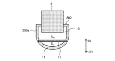
- FIG. 2 is a schematic diagram showing an example of the first heat exchanger 100a of the refrigeration cycle apparatus 1 according to Embodiment 1.
- FIG. The configuration of the first heat exchanger 100a, which serves as a condenser during cooling operation, will be described in detail below with reference to FIG.
- the 1st heat exchanger 100a may only be called the heat exchanger 100.
- FIG. 1st heat exchanger 100a may only be called the heat exchanger 100.
- the heat exchanger 100 includes a plurality of vertically extending heat transfer tubes 2 and fins 3 , a cylindrical first header 200 disposed below and extending horizontally, and and a cylindrical second header 300 disposed above and extending in the lateral direction.
- directional terms e.g., “up”, “down”, “right”, “left”, “front”, “back”, etc.
- first direction D1 and a second direction D2 two directions perpendicular to each other are defined as a first direction D1 and a second direction D2
- first direction D1 and a second direction D2 two directions perpendicular to each other are defined as a first direction D1 and a second direction D2
- first direction D1 and a second direction D2 two directions perpendicular to each other are defined as a first direction D1 and a second direction D2
- the longitudinal direction of the first header 200 and the second header 300 in the heat exchanger 100 that is, the lateral direction
- the longitudinal direction, that is, the vertical direction of the heat transfer tube 2 may be referred to as a second direction D2.
- the plurality of heat transfer tubes 2 are arranged at regular intervals in the first direction D1.
- the heat transfer tubes 2 are composed of flat tubes, for example. Both ends in the longitudinal direction of the plurality of heat transfer tubes 2 are connected to first and second headers 300 forming upper and lower portions of the heat exchanger 100 .
- the lower ends of the multiple heat transfer tubes 2 are inserted into the outer wall 200 a of the first header 200
- the upper ends of the multiple heat transfer tubes 2 are inserted into the outer wall 300 a of the second header 300 .
- Each of the plurality of fins 3 is composed of, for example, corrugated fins formed into a corrugated shape.
- Each fin 3 is arranged between adjacent heat transfer tubes 2 and joined to the surfaces of the heat transfer tubes 2 on both sides. The fins 3 transfer heat to the heat transfer tubes 2 and improve heat exchange efficiency between the air and the refrigerant.
- the first header 200 has a cylindrical outer wall 200a, and inside the first header 200 is formed a space through which a coolant flows.
- the second header 300 has a cylindrical outer wall 300a, and inside the second header 300, a space is formed through which a coolant flows.
- the space inside the first header 200 and the space inside the second header 300 communicate with each other through a plurality of heat transfer tubes 2 .
- the first header 200 and the second header 300 distribute the refrigerant and also combine the refrigerant.
- the first header 200 also has a partition plate 17 that divides the internal space of the first header 200 in the second direction D2.
- the partition plate 17 extends along the axial direction (first direction D1) of the first header 200 to axially partition the inside.
- the partition plate 17 is provided from one end to the other end in the longitudinal direction of the first header 200, and divides the internal space of the first header 200 into a space where the lower ends of the heat transfer tubes are arranged and a space where the lower ends of the heat transfer tubes are arranged. It is divided into a space where the department is not arranged.
- the space where the lower ends of the heat transfer tubes are arranged is the high-pressure refrigerant flow path 10 described above, and the space where the lower ends of the heat transfer tubes are not arranged. is the low-pressure refrigerant flow path 11 described above.
- the partition plate 17 be made of a metal material such as aluminum having good thermal conductivity.
- the plurality of heat transfer tubes 2, the plurality of fins 3, the first header 200, and the second header 300 can all be made of aluminum, and in this case, they are joined by brazing, for example.
- the heat exchanger 100 has a high-pressure refrigerant inlet 12 serving as an inlet for high-pressure refrigerant to the high-pressure refrigerant passage 10 and a high-pressure refrigerant outlet 14 serving as an outlet for high-pressure refrigerant from the high-pressure refrigerant passage 10 .
- the heat exchanger 100 also has a low-pressure refrigerant inlet 13 serving as an inlet of the low-pressure refrigerant to the low-pressure refrigerant passage 11 and a low-pressure refrigerant outlet 15 serving as an outlet of the low-pressure refrigerant from the low-pressure refrigerant passage 11. .
- a high-pressure refrigerant inlet 12 serving as an inlet for high-pressure refrigerant to the high-pressure refrigerant passage 10
- a high-pressure refrigerant outlet 14 serving as an outlet for high-pressure refrigerant from the high-pressure refrigerant passage 10 .
- the heat exchanger 100 also has a low-pressure ref
- the high pressure refrigerant inlet 12, the high pressure refrigerant outlet 14, the low pressure refrigerant inlet 13 and the low pressure refrigerant outlet 15 are all provided in the first header 200, and the high pressure refrigerant inlet 12 and the high pressure refrigerant outlet 14 are connected to the low pressure refrigerant outlet. It is provided above the refrigerant inlet 13 and the low-pressure refrigerant outlet 15 .
- the high-pressure refrigerant flow path 10 is provided in the main circuit C1 shown in FIG.
- the low-temperature, high-pressure liquid refrigerant after exchange flows out of the heat exchanger 100 through the high-pressure refrigerant outlet 14 .
- the low-pressure refrigerant flow path 11 is provided in the bypass circuit C2 shown in FIG.
- the low-pressure refrigerant decompressed by the second pressure reducer 8 flows into the heat exchanger 100 through the low-pressure refrigerant inlet 13, and after heat exchange through the partition plate 17, heat is transferred through the low-pressure refrigerant outlet 15. It flows out of the exchanger 100 .
- the first header 200 has a high pressure partition 16 that divides the high pressure refrigerant channel 10 in the longitudinal direction of the first header 200, that is, in the first direction D1.
- the high pressure partition 16 is provided in the high pressure refrigerant flow path 10 to separate the high pressure refrigerant flow path 10 into the left high pressure refrigerant flow path 10a on the high pressure refrigerant inlet 12 side and the right high pressure refrigerant flow path 10b on the high pressure refrigerant outlet 14 side.
- the high pressure refrigerant inlet 12 and the low pressure refrigerant outlet 15 are provided at one longitudinal end or left side of the first header 200, and the high pressure refrigerant outlet 14 and the low pressure refrigerant inlet 13 are provided in the first header 200. It is provided at the other longitudinal end, that is, on the right side.
- the high-pressure refrigerant flow path 10 in the internal space of the first header 200 causes the high-pressure refrigerant to flow from the left side to the right side of the first header 200 as indicated by the outline arrow F1.
- the low-pressure refrigerant flows from the right side to the left side of the first header 200 as indicated by the black arrow F2, and the high-pressure refrigerant and the low-pressure refrigerant flow countercurrently.
- one or both of the high pressure refrigerant inlet 12 and the high pressure refrigerant outlet 14 can be provided in the second header 300 .
- the first header 200 provided with the partition plate 17 of the first header 200 and the second header 300 is provided with the high-pressure refrigerant outlet 14 . The reason will be explained below.
- the refrigeration cycle apparatus 1 includes a fan (not shown) that supplies outside air to the heat exchanger 100, and the outside air supplied by the fan flows between adjacent heat transfer tubes 2 in the heat exchanger 100. , flows through the gap between the fin 3 and the heat transfer tube 2 . Specifically, outside air passes through the heat exchanger 100 in a direction perpendicular to both the first direction D1 and the second direction D2, that is, from the front to the back of the paper surface of FIG. The high-temperature, high-pressure gas refrigerant that has flowed into the heat exchanger 100 is cooled while passing through the heat transfer tubes 2 and becomes a liquid refrigerant before the high-pressure refrigerant outlet 14 .
- the liquid refrigerant flows through the partition plate 17 in the right high-pressure refrigerant flow path 10b on the high-pressure refrigerant outlet 14 side. It is further cooled by heat exchange with the low pressure refrigerant. Therefore, after passing through the heat transfer tube 2, the high pressure refrigerant is further condensed in the right high pressure refrigerant flow path 10b, and the degree of supercooling is increased, so that the heat transfer tube 2 alone does not need to be sufficiently cooled.
- the ratio of the gas-liquid two-phase refrigerant which is considered to be the most efficient for heat exchange with the outside air, may be high.
- the amount of heat exchange in the heat transfer tubes 2 can be increased by preventing the liquid refrigerant from being completely converted to a liquid refrigerant.
- the partition plate 17, the high-pressure refrigerant channel 10, and the low-pressure refrigerant channel 11 in the first header 200 will be described in detail below.
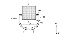
- FIG. 3 is a cross-sectional view of the first header 200 in the first heat exchanger 100a of FIG. 2 as seen from the first direction D1.
- the partition plate 17 is formed in a substantially rectangular shape having a longitudinal direction in the first direction D ⁇ b>1 in a plan view, and both longitudinally extending end surfaces thereof are connected to the inner surface of the outer wall 200 a of the first header 200 .
- the cross-sectional area SH of the high-pressure refrigerant flow path 10 is larger than the cross- sectional area SL of the low-pressure refrigerant flow path 11.
- a partition plate 17 is arranged.
- FIG. 4 is a schematic diagram showing the relationship between the thickness t2 of the outer wall 200a and the thickness t1 of the partition plate 17 in the first header 200 of FIG.
- the outer wall 200a of the first header 200 has a substantially constant thickness t2.
- the plate thickness t1 of the partition plate 17 that partitions the high-pressure refrigerant channel 10 and the low-pressure refrigerant channel 11 is configured to be thinner than the thickness t2 of the outer wall 200a of the first header 200 .
- the plate thickness t1 of the partition plate 17 By defining the plate thickness t1 of the partition plate 17 in this way, the heat of both the high-pressure refrigerant and the low-pressure refrigerant is more likely to be conducted to the partition plate 17 than the outer wall 200a, and the high-pressure refrigerant and the low-pressure refrigerant flow through the partition plate 17. heat exchange is promoted. Therefore, when the heat exchanger 100 functions as a condenser, the high-pressure refrigerant is likely to be supercooled at the condenser outlet, and the condensation performance is improved by increasing the gas-liquid two-phase region in the condenser. can be made.
- the plate thickness t1 of the partition plate 17 can be thin, an increase in cost due to the provision of the partition plate 17 can be suppressed. Since the refrigerant flows on both sides of the partition plate 17, uneven pressure applied to both sides of the partition plate 17 can be suppressed, the required pressure resistance can be reduced, and there is no problem even if the plate thickness t1 is
- the configuration of the heat exchanger 100 is not limited to this.
- the high-pressure refrigerant flowing into the high-pressure refrigerant flow path 10 of the heat exchanger 100 is not limited to a high-pressure gas single-phase refrigerant, and may be a high-pressure gas-liquid two-phase refrigerant.
- the fluid that exchanges heat with the refrigerant in the heat exchanger 100 may be a fluid other than air.
- the fins 3 since heat exchange between the air and the refrigerant is performed by the heat transfer tubes 2, the fins 3 may be omitted.
- the high pressure partition 16 may be omitted, or a plurality of partitions may be provided in the first header 200 .
- the high-pressure refrigerant channel 10 and the low-pressure refrigerant channel 11 of the first header 200 can be continuously provided from one longitudinal end to the other longitudinal end. can be created, making it easier to create.
- the second header 300 is provided with the high-pressure partition 16 at a position different from the position where the high-pressure partition 16 is provided in the first header 200 in the first direction D1, and the high-pressure refrigerant flows in the heat exchanger 100 by folding back multiple times. Channels can also be formed.
- the partition plate 17 may be provided on the second header 300 as well as the first header 200 . Modifications will be described below.
- FIG. 5 is a schematic diagram showing a first modification of the heat exchanger of FIG.
- a plurality of high pressure partitions 16 are provided in the first modification.
- two high pressure partitions 16 are provided in the first header 200 and one high pressure partition 16 is provided in the second header 300 .
- the high-pressure refrigerant flow path 10 of the first header 200 is divided by two high-pressure partitions 16 into three, a left high-pressure refrigerant flow path 10a, a central high-pressure refrigerant flow path 10c, and a right high-pressure refrigerant flow path 10b.
- the internal space of 300 is divided into left and right by one high pressure partition 16 .
- the high-pressure refrigerant that has flowed into the heat exchanger 100 from the high-pressure refrigerant inlet 12 first flows into the left high-pressure refrigerant flow path 10a of the first header 200, and is connected to the left high-pressure refrigerant flow path 10a. It flows through the heat transfer tube 2 into the left space in the second header 300 and merges.
- the high-pressure refrigerant that has flowed into the left space in the second header 300 passes through the plurality of left heat transfer tubes among the plurality of heat transfer tubes connected to the central high pressure refrigerant flow path 10c of the first header 200, and flows through the first header 200. flows into the central high-pressure refrigerant flow path 10c and merges.
- the high-pressure refrigerant passes through the plurality of heat transfer tubes on the right side among the plurality of heat transfer tubes connected to the central high-pressure refrigerant flow path 10c of the first header 200, flows into the space on the right side of the second header 300, and joins. do.
- the high-pressure refrigerant that has flowed into the space on the right side of the second header 300 passes through a plurality of heat transfer tubes connected to the right-side high-pressure refrigerant flow path 10b of the first header 200 and into the right-side high-pressure refrigerant flow path 10b of the first header 200. flow in and merge.
- the high-pressure refrigerant can reciprocate between the first header 200 and the second header 300 according to the number of partitions, and can form a path for flowing out from the high-pressure refrigerant outlet 14 . .
- the locations of the high-pressure refrigerant inlet 12 and the high-pressure refrigerant outlet 14 may be appropriately determined according to the number of high-pressure partitions 16 provided in the first header 200 and the number of high-pressure partitions 16 provided in the second header 300 .
- FIG. 6 is a schematic diagram showing a second modification of the heat exchanger of FIG.
- both the high-pressure refrigerant inlet 12 and the low-pressure refrigerant inlet 13 are provided at the same longitudinal end of the first header 200, ie, the left side.
- both the high-pressure refrigerant outlet 14 and the low-pressure refrigerant outlet 15 are provided at the other longitudinal end of the first header 200, that is, on the right side.
- the high-pressure refrigerant inlet 12 and the low-pressure refrigerant inlet 13 on the same side in the longitudinal direction of the first header 200, the high-pressure refrigerant and the low-pressure refrigerant flowing through the first header flow in parallel and flow in the same direction. flow. Therefore, when the heat exchanger 100 is connected to the refrigerant circuit C shown in FIG. 1, the paired alternating current or the parallel flow can be selected as appropriate, increasing the versatility of the circuit configuration.
- FIG. 7 is a schematic diagram showing a third modification of the heat exchanger of FIG.
- the second header 300 is also provided with a partition plate 17 in the same manner as the first header 200, and the partition plate 17 allows the internal space of the second header 300 to prevent the flow of high-pressure refrigerant. It is partitioned into a channel 10 and a low-pressure refrigerant channel 11 .
- the high-pressure refrigerant inlet 12 is provided at one longitudinal end of the first header 200, ie, the left side, and the high-pressure refrigerant outlet 14 is provided at one longitudinal end, ie, the left side of the second header 300.
- FIG. 7 is a schematic diagram showing a third modification of the heat exchanger of FIG.
- the second header 300 is also provided with a partition plate 17 in the same manner as the first header 200, and the partition plate 17 allows the internal space of the second header 300 to prevent the flow of high-pressure refrigerant. It is partitioned into a channel 10 and a low-pressure refrig
- the heat exchanger 100 also includes a connection pipe 19 that connects the first header 200 and the second header 300 . It is configured to communicate with the path 11 .
- the low-pressure refrigerant inlet 13 is provided at one longitudinal end of the second header 300, ie, the left side, and the low-pressure refrigerant outlet 15 is provided at one longitudinal end, ie, the left side of the first header 200. As shown in FIG.
- the inlets and outlets of the refrigerant such as the high-pressure refrigerant inlet 12, the high-pressure refrigerant outlet 14, the low-pressure refrigerant inlet 13, and the low-pressure refrigerant outlet 15 can be collectively provided on the same side of the heat exchanger 100. Therefore, when the heat exchanger 100 is connected to the refrigerant circuit C at the time of installation of the refrigeration cycle device 1, it is possible to prevent the piping from becoming complicated. Therefore, for example, when the heat exchanger 100 is mounted on the outdoor unit of a refrigeration cycle apparatus such as a room air conditioner and a package air conditioner, it is easy to connect pipes and is excellent in compactness.
- a refrigeration cycle apparatus such as a room air conditioner and a package air conditioner
- the high-temperature and high-pressure gas refrigerant discharged from the compressor 6 flows through the flow switching device 7 into the first heat exchanger 100a.
- the high-temperature and high-pressure gas refrigerant that has flowed into the first heat exchanger 100a is condensed while exchanging heat with the outside air and releasing heat, and becomes a low-temperature and high-pressure liquid refrigerant and flows out of the first heat exchanger 100a.
- the low-temperature and high-pressure liquid refrigerant that has flowed out of the first heat exchanger 100a most of it flows to the first pressure reducer 5 of the main circuit C1, is decompressed by the first pressure reducer 5, and is low-temperature and low-pressure gas-liquid two-phase refrigerant or It becomes a liquid refrigerant and flows into the second heat exchanger 100b.
- the low-temperature, low-pressure gas-liquid two-phase refrigerant or liquid refrigerant that has flowed into the second heat exchanger 100b evaporates while exchanging heat with the indoor air and absorbing heat, cooling the indoor air and becoming a low-temperature, low-pressure gas refrigerant. 2 out of the heat exchanger 100b.
- the remaining portion of the low-temperature, high-pressure liquid refrigerant that has flowed out of the first heat exchanger 100a in the main circuit C1 flows into the bypass circuit C2.
- the low-temperature and high-pressure liquid refrigerant that has flowed into the bypass circuit C2 passes through the check valve 9, flows into the second pressure reducer 8, is decompressed by the second pressure reducer 8, and becomes a low-temperature and low-pressure gas-liquid two-phase refrigerant. 1 flows into the low-pressure refrigerant channel 11 of the heat exchanger 100a. As shown in FIG.
- the low-temperature, low-pressure gas-liquid two-phase refrigerant that has flowed into the low-pressure refrigerant flow path 11 of the first heat exchanger 100a is composed of the high-pressure refrigerant flowing through the high-pressure refrigerant flow path 10 in the first header 200, Heat exchange is performed via the partition plate 17 .
- the low-temperature, low-pressure gas-liquid two-phase refrigerant flowing through the low-pressure refrigerant flow path 11 absorbs heat from the high-pressure refrigerant and is supercooled to become a low-temperature, low-pressure gas refrigerant, and flows out of the first heat exchanger 100a.
- the low-temperature, low-pressure gas refrigerant that has flowed out of the low-pressure refrigerant flow path 11 of the first heat exchanger 100a in the bypass circuit C2 joins the low-temperature, low-pressure gas refrigerant that has flowed out of the second heat exchanger 100b of the main circuit C1 at the junction T2. merge.
- the refrigeration cycle device 1 of the present disclosure during cooling operation, part of the refrigerant flowing through the main circuit C1 is branched before the first pressure reducer 5, so that it flows into the evaporator (second heat exchanger 100b).
- the amount of refrigerant used is reduced. Therefore, when a refrigerant with large pressure loss is used, or under operating conditions with large load changes, performance degradation due to increased pressure loss in the evaporator can be suppressed.
- the refrigeration cycle apparatus 1 of Embodiment 1 includes at least the compressor 6, the condenser (first heat exchanger 100a), the first pressure reducer 5, and the evaporator (second heat exchanger 100b). It has a refrigerant circuit C connected by The condenser has a plurality of heat transfer tubes 2 extending in the vertical direction (second direction D2), and a first header 200 having a cylindrical outer wall 200a into which one ends of the plurality of heat transfer tubes 2 are inserted. , has The condenser also has a partition plate 17 that is provided from one end to the other end in the longitudinal direction (first direction D1) of the first header 200 and partitions the internal space of the first header 200 .
- the partition plate 17 divides the internal space of the first header 200 into a high-pressure refrigerant channel 10 in which one end of the plurality of heat transfer tubes 2 is arranged and a low-pressure refrigerant channel in which one end of the plurality of heat transfer tubes 2 is not arranged. Divide into 11. Moreover, the partition plate 17 exchanges heat between the high-pressure refrigerant flowing through the high-pressure refrigerant flow path 10 and the low-pressure refrigerant flowing through the low-pressure refrigerant flow path 11 inside the first header 200 .
- the contact area between the partition plate 17, which is the boundary between the high-pressure refrigerant flow path 10 and the low-pressure refrigerant flow path 11, and the liquid refrigerant in the high-pressure refrigerant flow path 10 becomes larger than before, and the low-pressure refrigerant in the heat exchanger 100 and the high-pressure refrigerant can be more effectively exchanged than before.
- the liquid refrigerant flowing out of the condenser (the first heat exchanger 100a) can be given a higher degree of supercooling than before during the cooling operation.
- the cross-sectional area SH of the high-pressure refrigerant channel 10 is larger than the cross- sectional area SL of the low-pressure refrigerant channel 11 along the longitudinal direction of the first header 200 .
- the phase separation of the low-pressure refrigerant into the gas phase and the liquid phase can be suppressed, and heat exchange with the high-pressure refrigerant via the partition plate 17 can be suppressed. is done more efficiently.
- the inlet of the high-pressure refrigerant channel 10 (high-pressure refrigerant inlet 12 ) is provided at one longitudinal end of the first header 200
- the inlet of the low-pressure refrigerant channel 11 (low-pressure refrigerant inlet 13 ) is provided at the first header 200 . It is provided at the other end in the longitudinal direction.
- Both the inlet of the high-pressure refrigerant channel 10 and the inlet of the low-pressure refrigerant channel 11 are provided at the same longitudinal end of the first header 200 .
- the high-pressure refrigerant and the low-pressure refrigerant flowing through the first header 200 can flow in parallel. Greater configuration versatility.
- the plate thickness t1 of the partition plate 17 is thinner than the thickness t2 of the outer wall 200a of the first header 200 .
- the plate thickness t1 of the partition plate 17 heat is more easily transferred to the partition plate 17 than to the outer wall 200a, and heat exchange between the high-pressure refrigerant and the low-pressure refrigerant via the partition plate 17 is promoted. Therefore, when the heat exchanger 100 functions as a condenser, the high-pressure refrigerant is likely to be supercooled at the outlet of the condenser.
- the plate thickness t1 of the partition plate 17 can be thin, an increase in cost due to the provision of the partition plate 17 can be suppressed.
- the first header 200 provided with the partition plate 17 is provided with the high-pressure refrigerant outlet (high-pressure refrigerant outlet 14) in the condenser.
- the high-pressure refrigerant does not have to be completely liquid when it flows from the heat transfer tubes 2 into the first header 200. Heat exchange in the heat transfer tubes 2 can be facilitated, and the condensation performance of the condenser can be improved.
- the refrigeration cycle device 1 has a cylindrical shape, and the second header 300 into which the other ends of the plurality of heat transfer tubes 2 are inserted, and the space inside the second header 300 are divided into the high-pressure refrigerant flow path 10 and the low-pressure flow path. and a partition plate 17 that partitions into the coolant channel 11 .
- the condenser has a connection pipe 19 that connects the low-pressure refrigerant flow path 11 of the first header 200 and the low-pressure refrigerant flow path 11 of the second header 300 .
- a gas-liquid two-phase or gas single-phase refrigerant flows into the high-pressure refrigerant flow path 10 of the condenser, and the condenser condenses the refrigerant flowing into the high-pressure refrigerant flow path 10 into liquid refrigerant. .
- the configuration of the refrigerant circuit C and the type of refrigerant can be made versatile.
- the refrigeration cycle device 1 also has a main circuit C1 in which at least the compressor 6, the condenser, the first pressure reducer 5, and the evaporator are connected by piping, and a bypass circuit C2 branched from the main circuit C1.
- the bypass circuit C2 includes a bypass pipe Pb that connects a pipe P1 between the condenser and the first pressure reducer 5 in the main circuit C1 and a pipe P2 between the evaporator and the compressor 6 in the main circuit C1. have.
- the bypass circuit C2 also has a second pressure reducer 8 that is provided in the bypass pipe Pb and reduces the pressure of the refrigerant.
- the high-pressure refrigerant flow path 10 of the condenser is connected to the piping of the main circuit C1 and constitutes a part of the main circuit C1, and the low-pressure refrigerant flow path 11 of the condenser is connected to the second pressure reducer 8 in the bypass piping Pb. and the compressor 6, forming a part of the bypass circuit C2.
- part of the refrigerant flowing through the main circuit C1 is branched before the first pressure reducer 5 and flows into the evaporator (second heat exchanger 100b). Refrigerant is reduced. Therefore, when a refrigerant with large pressure loss is used, or under operating conditions with large load changes, performance degradation due to increased pressure loss in the evaporator can be suppressed.
- FIG. 8 is a cross-sectional view showing the configuration of the first header 200 in the heat exchanger of the refrigeration cycle apparatus according to Embodiment 2.
- the shape of the partition plate 17 is different from that in the first embodiment, and the rest of the configuration is the same as in the first embodiment.
- the same reference numerals are given to the same parts as in the first embodiment, and the explanation will focus on the differences from the first embodiment.
- the partition plate 17 is formed in a substantially rectangular shape having a longitudinal direction in the first direction D1 in a plan view, and both end surfaces extending in the longitudinal direction are arranged in the first direction. It is connected to the inner surface of the outer wall 200 a of the header 200 .
- a recess 17a is formed in the upper surface of the partition plate 17 on the side of the high-pressure refrigerant channel 10.
- the recess 17a of the partition plate 17 has a shape in which the lower surface protrudes by recessing the upper surface of the partition plate 17 .
- the recess 17a extends in the longitudinal direction of the partition plate 17 and is formed, for example, from one longitudinal end of the partition plate 17 to the other longitudinal end.
- substantially semicircular recesses 17a are provided at two locations in the width direction of the partition plate 17 .
- the shape of the upper surface and the lower surface of the partition plate 17 is not limited to the shape described above, and the partition plate 17 is provided with at least one of a downward recess and an upward protrusion so as to increase the surface area. It is good if it is for example, the partition plate 17 may be provided with three or more recesses or protrusions so as to promote heat conduction, the partition plate 17 may be formed in a corrugated shape, or the partition plate 17 may be provided with a dimple structure.
- the partition plate 17 is provided with at least one of the recess 17a and the protrusion.
- the unevenness of the partition plate 17, such as the depressions 17a and the protrusions increases the surface area of the partition plate 17 compared to the case where the partition plate 17 is flat, and the heat transfer area between the high-pressure refrigerant and the low-pressure refrigerant increases. The amount of heat exchange increases, and the high-pressure refrigerant is more likely to be subcooled.
- the liquid surface of the high-pressure refrigerant easily spreads along the uneven surface of the partition plate 17, even when the high-pressure refrigerant separates into two phases, the gas phase and the liquid phase, the liquid refrigerant exists on the partition plate 17 side. It is possible to suppress the decrease in the amount of heat exchange such as
- Embodiment 3. 9 is a cross-sectional view showing the configuration of the first header in the heat exchanger of the refrigeration cycle apparatus according to Embodiment 3.
- FIG. The third embodiment is different from the first embodiment in that it includes a sub-partition plate 18, and the rest of the configuration is the same as that of the first embodiment.
- the same reference numerals are given to the same parts as in the first embodiment, and the explanation will focus on the differences from the first embodiment.
- the partition plate 17 is formed in a substantially rectangular shape having a longitudinal direction in the first direction D1 in plan view, has a flat plate shape, and extends in the longitudinal direction. Both extending end surfaces are connected to the inner surface of the outer wall 200 a of the first header 200 .
- the first header 200 further includes a sub-partition plate 18 provided above the partition plate 17 .
- the sub partition plate 18 is formed in a substantially rectangular shape having a longitudinal direction in the first direction D1, and has a flat plate shape. connected to the inside.
- the sub-partition plate 18 is provided from one end to the other end in the longitudinal direction of the first header 200, and divides the high-pressure refrigerant flow path 10 into a first high-pressure refrigerant flow path 101 in which the lower ends of the plurality of heat transfer tubes 2 are arranged, 2nd high pressure refrigerant
- the sub-partition plate 18 is formed with a plurality of holes 18a that allow the first high-pressure refrigerant channel 101 and the second high-pressure refrigerant channel 102 to communicate with each other.
- a plurality of holes 18 a are provided along the longitudinal direction of the sub-partition plate 18 , that is, along the longitudinal direction of the first header 200 .
- the holes 18a of the sub-partition plate 18 are also provided in a plurality (for example, two places) in the lateral direction of the sub-partition plate 18. As shown in FIG.
- a high-pressure refrigerant inlet 12 (see FIG. 2), which is an inlet for high-pressure refrigerant, is provided in the first header 200 so as to be connected to the lower second high-pressure refrigerant flow path 102 in the high-pressure refrigerant flow path 10 .
- the high pressure refrigerant that has flowed into the heat exchanger 100 via the high pressure refrigerant inlet 12 first flows into the second high pressure refrigerant flow path 102 in the first header 200 .
- the sub-partition plate 18 need not be provided all over the first header 200 in the longitudinal direction, but may be provided in a part of the first header 200. It is good if there is Also, the sub-partition plate 18 can be provided on the second header 300 or on each of the first header 200 and the second header 300 .
- FIG. 10 is a schematic diagram showing a fourth modification of the heat exchanger 100 of FIG.
- the heat exchanger 100 of the fourth modification includes the high pressure partition 16 of the first embodiment (see FIG. 2) and the second header 300 and the second header 300 of the third modification (see FIG. 7).
- the configuration includes partition plates 17 provided on both sides of one header 200 and sub-partition plates 18 of the third embodiment.
- one high-pressure partition 16 is provided in the longitudinal center of the first header 200, and the high-pressure partition 16 separates the high-pressure refrigerant passage 10 of the first header 200 from the left high-pressure refrigerant passage 10a and the right side. It is partitioned off from the high-pressure refrigerant channel 10b. That is, in the fourth modification, the configuration of the first header 200 is the same as the example shown in FIG. The high-pressure refrigerant outlet 14 and the low-pressure refrigerant inlet 13 are provided at the other longitudinal end of the first header 200, ie, the right side.
- the second header 300 is also provided with the low-pressure refrigerant inlet 13 and the low-pressure refrigerant outlet 15 .
- the low-pressure refrigerant inlet 13 is provided at one longitudinal end, ie, the left side of the second header 300
- the low-pressure refrigerant outlet 15 is provided at the other longitudinal end, ie, the right side of the second header 300.
- the sub-partition plate 18 is provided in a part of the second header 300 in the longitudinal direction.
- the heat exchanger 100 of the fourth modification has a support plate 20 extending in the second direction D2 substantially parallel to the heat transfer tubes 2 from the side of the outer wall 300a of the second header 300 into which the heat transfer tubes 2 are inserted.
- the upper end of the plate 20 supports the end 18e of the sub-partition plate 18. As shown in FIG. The upper end of the support plate 20 and the end portion 18e of the sub-partition plate 18 are connected.
- the upper end of the support plate 20 is arranged in the second direction D2 so that the high-pressure refrigerant can flow between the sub-partition plate 18 and the partition plate 17 and between the sub-partition plate 18 and the upper ends of the plurality of heat transfer tubes 2. is located between the upper end surface of the heat transfer tube 2 and the partition plate 17 .
- the sub-partition plate 18 is provided from the center to the other end in the longitudinal direction of the second header 300, that is, the right half, and the support plate 20 is provided in the longitudinal direction of the second header 300. located in the center.
- the right end of the sub-partition plate 18 is connected to the other end, ie, the right side, of the second header 300 and supported, and the left end 18 e of the sub-partition plate 18 is supported by the support plate 20 .
- the range in which the sub-partition plate 18 is provided may be appropriately set according to the arrangement of the high-pressure partition 16, the high-pressure refrigerant inlet 12, and the high-pressure refrigerant outlet 14. FIG.
- the high-pressure refrigerant that has flowed into the left-side high-pressure refrigerant flow path 10a of the first header 200 through the high-pressure refrigerant inlet 12 passes through the plurality of left-side heat transfer tubes 2 and enters the second header 300.
- flow into The high-pressure refrigerant that has flowed into the second header 300 flows to the right, and flows from the second high-pressure refrigerant flow path 102 above the sub-partition plate 18 into the first high-pressure refrigerant flow path 101 through the plurality of holes 18a. , through the plurality of heat transfer tubes 2 on the right side, and flows into the right high-pressure refrigerant flow path 10 b in the first header 200 .
- the high-pressure refrigerant that has flowed into the right high-pressure refrigerant flow path 10 b in the first header 200 flows out from the high-pressure refrigerant outlet 14 provided in the first header 200 .
- the low-pressure refrigerant flows from the left side to the right side in the low-pressure refrigerant passage 11 of the second header 300, and the low-pressure refrigerant passage 11 of the first header 200 flows from the right side.
- a low-pressure refrigerant flows toward the left.
- the high-pressure refrigerant flowing in and out through the high-pressure refrigerant inlet 12 and the high-pressure refrigerant outlet 14 provided in the first header 200 flows through the first header 200 and the second header 300, respectively. can perform heat exchange with the low-pressure refrigerant.
- the refrigeration cycle apparatus 1 of Embodiment 3 includes the sub-partition plate 18 provided on a part or the entire length of the first header in the longitudinal direction.
- the sub-partition plate 18 and the high-pressure refrigerant flow path 10 are divided into a first high-pressure refrigerant flow path 101 in which one ends of the plurality of heat transfer tubes 2 are arranged, a second high-pressure refrigerant flow path 102 on the low-pressure refrigerant flow path 11 side, divide into
- the sub-partition plate 18 is formed with a plurality of holes 18a that allow the first high-pressure refrigerant flow path 101 and the second high-pressure refrigerant flow path 102 to communicate with each other.
- the liquid phase with a high heat transfer coefficient is moved to the low-pressure refrigerant flow path 11 side by narrowing the area into which the high-pressure refrigerant flows by the sub partition plate 18 . , and heat exchange with the low-pressure refrigerant via the partition plate 17 can be promoted.
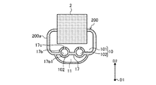
- Embodiment 4. 11 is a cross-sectional view showing the configuration of the first header in the heat exchanger of the refrigeration cycle apparatus according to Embodiment 4.
- FIG. The fourth embodiment differs from the first embodiment in that the partition plate 17 has a cylindrical portion, and the rest of the configuration is the same as the first embodiment.
- the same reference numerals are given to the same parts as in the first embodiment, and the explanation will focus on the differences from the first embodiment.
- the partition plate 17 is formed in a substantially rectangular shape having a longitudinal direction in the first direction D1 in a plan view, and both end surfaces extending in the longitudinal direction are arranged in the first direction D1. It is connected to the inner surface of the outer wall 200 a of the header 200 .
- the partition plate 17 has at least one cylindrical portion 17b extending in the longitudinal direction of the first header 200, that is, in the first direction D1.
- the tubular portion 17b can be provided, for example, from one end to the other end in the longitudinal direction of the partition plate 17 .
- the partition plate 17 is formed with a plurality of holes 17c that allow communication between the space in which the lower end portions of the heat transfer tubes 2 are arranged and the internal space of the cylindrical portion 17b.
- first high pressure refrigerant flow channel 101 the space outside the partition plate 17 in which the lower end portions of the plurality of heat transfer tubes 2 are arranged in the high pressure refrigerant flow channel 10
- tubular portion 17b of the partition plate 17 is referred to as a first high pressure refrigerant flow channel 101.
- the internal space may be called a second high-pressure refrigerant flow path 102 . That is, the second high-pressure refrigerant flow path 102 formed between the partition plate 17 and the sub-partition plate 18 in the third embodiment is provided inside the partition plate 17 in the fourth embodiment. No plate 18 is required.
- a plurality of holes 17c are provided along the longitudinal direction of the partition plate 17, that is, along the longitudinal direction of the first header 200.
- a plurality of (for example, two) cylindrical portions 17b are provided in the lateral direction of the partition plate 17, and each cylindrical portion 17b has a plurality of holes along the longitudinal direction. 17c is provided.
- the cylindrical portion 17b has an inner peripheral surface 17b1 that is curved in cross section.
- the cylindrical portion 17b has a cylindrical shape
- the cross section of the second high-pressure refrigerant flow path 102 has a circular shape.
- a plurality of holes 17c are provided in the upper wall surface of the cylindrical portion 17b that protrudes toward the first high-pressure refrigerant flow path 101, and the upper wall surface is a shower pipe. function as Therefore, the high-pressure refrigerant can easily flow into the openings at the lower ends of the plurality of heat transfer tubes 2 inserted into the outer wall 200a of the first header 200 from the opposed cylindrical portions 17b.
- the high-pressure refrigerant flows into the heat transfer tubes 2 of the first high-pressure refrigerant flow path 101 after passing through the second high-pressure refrigerant flow path 102, an effect of improving distribution can be obtained.
- the area where the proportion of the liquid phase is high that is, the high-pressure refrigerant outlet 14 Heat exchange can be performed while ensuring good distribution in the right high-pressure refrigerant flow path 10b. Therefore, the performance of the entire condenser can be improved.
- the cylindrical portion 17b need not be provided over the entire longitudinal direction of the first header 200, but may be provided only partially. Just do it.
- the configuration of the partition plate 17, such as the shape of the tubular portion 17b, the number of tubular portions 17b, and the positions and numbers of the holes 17c, are not limited to those described above.
- the partition plate 17 having one second high-pressure refrigerant flow path 102 may be formed by combining two arcuate plate members.
- the position of the hole 17c in the partition plate 17 may be set at any position as long as the first high-pressure refrigerant channel 101 and the second high-pressure refrigerant channel 102 communicate with each other.
- all the coolant flow paths formed in the internal space of the first header 200 may have a curved shape with no corners. In this case, since the pressure resistance strength of the first header 200 is improved, the thickness t2 (see FIG. 4) of the outer wall 200a of the first header 200 can be reduced to reduce the cost.
- the high-pressure partition 16 may be omitted, or a plurality thereof may be provided in the first header 200 .
- the high-pressure refrigerant channel 10 and the low-pressure refrigerant channel 11 of the first header 200 can be continuously provided from one longitudinal end to the other longitudinal end. can be created, making it easier to create.
- the second header 300 is provided with the high-pressure partition 16 at a position different from the position where the high-pressure partition 16 is provided in the first header 200 in the first direction D1, and the high-pressure refrigerant flows in the heat exchanger 100 by folding back multiple times. Channels can also be formed.
- the partition plate 17 has at least one cylindrical portion 17b extending in the longitudinal direction of the first header 200. As shown in FIG. In the partition plate 17, a space (first high-pressure refrigerant flow path 101) in which one ends of the plurality of heat transfer tubes 2 are arranged communicates with an internal space (second high-pressure refrigerant flow path 102) of the tubular portion 17b. A plurality of holes 17c are formed.
- the area into which the high-pressure refrigerant flows can be narrowed by the cylindrical portion 17b. Therefore, in the fourth embodiment, as in the case of the third embodiment, even if the refrigerant is separated into the liquid phase and the gas phase, the liquid phase having a high heat transfer coefficient is transferred to the low-pressure refrigerant flow path 11 side. It is possible to facilitate heat exchange with the low-pressure refrigerant through the partition plate 17 .
- the cylindrical portion 17b has a cylindrical shape.
- the state of the high-pressure refrigerant in the inner space (second high-pressure refrigerant flow path 102) of the cylindrical portion 17b is easily transitioned to an annular flow, which is said to allow more efficient heat exchange, and the high-pressure refrigerant is two-phase. Even in the case of separation, heat exchange between the high-pressure liquid refrigerant and the low-pressure refrigerant can be efficiently performed.
- the tubular portion 17b functions as a shower pipe, and the high-pressure refrigerant from the tubular portion 17b easily flows into the openings at the lower end portions of the plurality of heat transfer tubes 2. As shown in FIG.
- each embodiment it is possible to combine each embodiment, and to modify or omit each embodiment as appropriate.
- the heat exchanger of the second, third or fourth embodiment can be used instead of the heat exchanger 100 in the refrigeration cycle apparatus 1 of the first embodiment.
Abstract
Description
(冷凍サイクル装置1)
図1は、実施の形態1に係る冷凍サイクル装置1の一例を示す冷媒回路図である。冷凍サイクル装置1は、冷媒の蒸発と凝縮の潜熱を利用して熱を移動させる冷媒回路Cを有している。冷凍サイクル装置1としては、例えば、凝縮器を室外に設置し、蒸発器を室内に設置して室内を冷房する空気調和機、及び、凝縮器で水を加熱して温水とする給湯システム等がある。
(Refrigeration cycle device 1)
FIG. 1 is a refrigerant circuit diagram showing an example of a
冷媒回路Cは、圧縮機6を含む主回路C1と、主回路C1から分岐したバイパス回路C2と、を有している。
(主回路C1)
主回路C1は、圧縮機6、第1熱交換器100a、第1減圧器5、及び第2熱交換器100bが配管により接続されて形成されている。圧縮機6は、低圧のガス冷媒を吸入し、圧縮し、高圧のガス冷媒にして吐出し、冷媒回路Cに循環させる。第1熱交換器100a及び第2熱交換器100bは、冷媒と空気とを熱交換させる。第1減圧器5は、例えば膨張弁で構成され、主回路C1において冷媒を膨張させ減圧させるものである。 (Refrigerant circuit C)
The refrigerant circuit C has a main circuit C1 including the
(Main circuit C1)
The main circuit C1 is formed by connecting the
バイパス回路C2は、配管(以下、バイパス配管Pbという)と、バイパス配管Pbに設けられ、冷媒を減圧する第2減圧器8と、冷媒が流れる方向を規制する逆止弁9と、を有する。図1に示される例では、バイパス回路C2は、主回路C1において第1熱交換器100aと第1減圧器5とを接続する配管P1から分岐され、主回路C1において第2熱交換器100bから圧縮機6に戻る冷媒が流通する配管P2に合流する構成とされる。 (Bypass circuit C2)
The bypass circuit C2 includes a pipe (hereinafter referred to as a bypass pipe Pb), a
図8は、実施の形態2に係る冷凍サイクル装置の熱交換器における第1ヘッダ200の構成を示す断面図である。実施の形態2では、仕切り板17の形状が、実施の形態1の場合とは異なり、その他の構成は実施の形態1の場合と同様である。実施の形態2では、実施の形態1と同一部分には同一符号を付し、実施の形態1との相違点を中心に説明するものとする。
FIG. 8 is a cross-sectional view showing the configuration of the
図9は、実施の形態3に係る冷凍サイクル装置の熱交換器における第1ヘッダの構成を示す断面図である。実施の形態3では、副仕切り板18を備える点が、実施の形態1の場合とは異なり、その他の構成は実施の形態1の場合と同様である。実施の形態3では、実施の形態1と同一部分には同一符号を付し、実施の形態1との相違点を中心に説明するものとする。
9 is a cross-sectional view showing the configuration of the first header in the heat exchanger of the refrigeration cycle apparatus according to
図11は、実施の形態4に係る冷凍サイクル装置の熱交換器における第1ヘッダの構成を示す断面図である。実施の形態4では、仕切り板17が筒状部を有する点が、実施の形態1の場合とは異なり、その他の構成は実施の形態1の場合と同様である。実施の形態2では、実施の形態1と同一部分には同一符号を付し、実施の形態1との相違点を中心に説明するものとする。 Embodiment 4.
11 is a cross-sectional view showing the configuration of the first header in the heat exchanger of the refrigeration cycle apparatus according to Embodiment 4. FIG. The fourth embodiment differs from the first embodiment in that the
Claims (15)
- 少なくとも圧縮機、凝縮器、第1減圧器及び蒸発器が配管により接続された冷媒回路を有する冷凍サイクル装置において、
前記凝縮器は、
上下方向に延びる複数の伝熱管と、
筒形状の外壁を有し、前記外壁に、前記複数の伝熱管の一端部が差し込まれた第1ヘッダと、
前記第1ヘッダの長手方向の一端から他端まで設けられ、前記第1ヘッダの内部空間を、前記複数の伝熱管の一端部が配置された高圧冷媒流路と、前記複数の伝熱管の一端部が配置されていない低圧冷媒流路と、に仕切るものであって、前記第1ヘッダの内部において前記高圧冷媒流路を流れる高圧冷媒と前記低圧冷媒流路を流れる低圧冷媒との熱交換を行う仕切り板と、を備えた
冷凍サイクル装置。 In a refrigeration cycle device having a refrigerant circuit in which at least a compressor, a condenser, a first pressure reducer and an evaporator are connected by piping,
The condenser is
a plurality of heat transfer tubes extending in the vertical direction;
a first header having a cylindrical outer wall into which one ends of the plurality of heat transfer tubes are inserted;
The first header is provided from one longitudinal end to the other longitudinal end of the first header, and the internal space of the first header is defined by a high-pressure refrigerant channel in which one end of the plurality of heat transfer tubes is arranged, and one end of the plurality of heat transfer tubes. and a low-pressure refrigerant channel in which no part is arranged, and heat exchange is performed between the high-pressure refrigerant flowing through the high-pressure refrigerant channel and the low-pressure refrigerant flowing through the low-pressure refrigerant channel inside the first header. A refrigeration cycle device comprising: - 前記第1ヘッダの前記長手方向にわたり、前記高圧冷媒流路の流路断面積は、前記低圧冷媒流路の流路断面積よりも大きい
請求項1に記載の冷凍サイクル装置。 The refrigeration cycle apparatus according to claim 1, wherein the cross-sectional area of the high-pressure refrigerant channel is larger than the cross-sectional area of the low-pressure refrigerant channel over the longitudinal direction of the first header. - 前記高圧冷媒流路の入口は、前記第1ヘッダの長手方向の一端に設けられ、
前記低圧冷媒流路の入口は、前記第1ヘッダの長手方向の他端に設けられている
請求項1又は2に記載の冷凍サイクル装置。 an inlet of the high-pressure refrigerant channel is provided at one longitudinal end of the first header;
3. The refrigerating cycle apparatus according to claim 1, wherein an inlet of said low-pressure refrigerant channel is provided at the other longitudinal end of said first header. - 前記高圧冷媒流路の入口及び前記低圧冷媒流路の入口はいずれも、前記第1ヘッダの長手方向の同じ一端に設けられている
請求項1又は2に記載の冷凍サイクル装置。 3. The refrigeration cycle apparatus according to claim 1, wherein both the inlet of the high-pressure refrigerant channel and the inlet of the low-pressure refrigerant channel are provided at the same longitudinal end of the first header. - 前記仕切り板の板厚は、前記第1ヘッダの外壁の厚さよりも薄い
請求項1~4のいずれか一項に記載の冷凍サイクル装置。 The refrigeration cycle apparatus according to any one of claims 1 to 4, wherein the thickness of the partition plate is thinner than the thickness of the outer wall of the first header. - 前記仕切り板には、凹み及び出っ張りの少なくとも一方が設けられている
請求項1~5のいずれか一項に記載の冷凍サイクル装置。 The refrigeration cycle apparatus according to any one of claims 1 to 5, wherein the partition plate is provided with at least one of a recess and a protrusion. - 前記第1ヘッダの長手方向の一部又は全域に設けられ、前記高圧冷媒流路を、前記複数の伝熱管の一端部が配置された第1高圧冷媒流路と、前記低圧冷媒流路の側の第2高圧冷媒流路と、に仕切る副仕切り板を備え、
前記副仕切り板には、前記第1高圧冷媒流路と前記第2高圧冷媒流路とを連通させる複数の穴が形成されている
請求項1~6のいずれか一項に記載の冷凍サイクル装置。 A first high-pressure refrigerant flow path provided in a part or the entire length of the first header, and the high-pressure refrigerant flow path having one end portion of the plurality of heat transfer tubes arranged thereon, and the low-pressure refrigerant flow path side A second high-pressure refrigerant flow path and a sub-partition plate that partitions into
The refrigeration cycle apparatus according to any one of claims 1 to 6, wherein the sub-partition plate is formed with a plurality of holes that allow communication between the first high-pressure refrigerant flow path and the second high-pressure refrigerant flow path. . - 前記仕切り板は、前記第1ヘッダの長手方向に延びた少なくとも1つの筒状部を有し、
前記仕切り板には、前記複数の伝熱管の一端部が配置された空間と、前記筒状部の内部空間とを連通させる複数の穴が形成されている
請求項1~6のいずれか一項に記載の冷凍サイクル装置。 The partition plate has at least one cylindrical portion extending in the longitudinal direction of the first header,
The partition plate is formed with a plurality of holes that communicate between the space in which one end of the plurality of heat transfer tubes is arranged and the inner space of the cylindrical portion. The refrigeration cycle device according to . - 前記筒状部は、円筒形状を有する
請求項8に記載の冷凍サイクル装置。 The refrigeration cycle apparatus according to claim 8, wherein the cylindrical portion has a cylindrical shape. - 前記凝縮器において、前記仕切り板が設けられた前記第1ヘッダに、前記凝縮器における前記高圧冷媒の出口が設けられている
請求項1~9のいずれか一項に記載の冷凍サイクル装置。 The refrigeration cycle apparatus according to any one of claims 1 to 9, wherein in the condenser, the first header provided with the partition plate is provided with an outlet for the high-pressure refrigerant in the condenser. - 筒形状を有し、前記複数の伝熱管の他端部が差し込まれた第2ヘッダと、
前記第2ヘッダの長手方向の一端から他端まで設けられ、前記第2ヘッダの内部の空間を、前記複数の伝熱管の他端部が配置された高圧冷媒流路と、前記高圧冷媒流路よりも前記複数の伝熱管から遠い側の低圧冷媒流路と、に仕切るものであって、前記第2ヘッダの内部において前記高圧冷媒流路を流れる高圧冷媒と前記低圧冷媒流路を流れる低圧冷媒との熱交換を行う仕切り板と、を備えた
請求項1~10のいずれか一項に記載の冷凍サイクル装置。 a second header having a tubular shape and into which the other ends of the plurality of heat transfer tubes are inserted;
The space inside the second header is defined from one end to the other end in the longitudinal direction of the second header. and a low-pressure refrigerant channel farther from the plurality of heat transfer tubes than the second header. The refrigeration cycle apparatus according to any one of claims 1 to 10, further comprising a partition plate that exchanges heat with the - 前記凝縮器は、前記第1ヘッダの前記低圧冷媒流路と前記第2ヘッダの前記低圧冷媒流路とを連通させる接続配管を有している
請求項11に記載の冷凍サイクル装置。 12. The refrigerating cycle apparatus according to claim 11, wherein the condenser has a connection pipe that communicates the low-pressure refrigerant channel of the first header and the low-pressure refrigerant channel of the second header. - 前記凝縮器の前記高圧冷媒流路には、気液二相又はガス単相の冷媒が流入し、前記凝縮器は、前記高圧冷媒流路に流入した冷媒を凝縮させ液冷媒にするものである
請求項1~12のいずれか一項に記載の冷凍サイクル装置。 A gas-liquid two-phase or gas single-phase refrigerant flows into the high-pressure refrigerant flow path of the condenser, and the condenser condenses the refrigerant flowing into the high-pressure refrigerant flow path into a liquid refrigerant. The refrigeration cycle apparatus according to any one of claims 1-12. - 前記仕切り板は、金属材料で構成されている
請求項1~13のいずれか一項に記載の冷凍サイクル装置。 The refrigeration cycle apparatus according to any one of claims 1 to 13, wherein the partition plate is made of a metal material. - 少なくとも前記圧縮機と前記凝縮器と前記第1減圧器と前記蒸発器とが配管により接続された主回路と、
前記主回路における前記凝縮器と前記第1減圧器との間の配管と、前記主回路における前記蒸発器と前記圧縮機との間の配管と、を接続するバイパス配管、及び、前記バイパス配管に設けられ、冷媒を減圧する第2減圧器を有するバイパス回路と、を備え、
前記凝縮器の前記高圧冷媒流路は、前記主回路の配管に接続され、前記主回路の一部を構成し、
前記凝縮器の前記低圧冷媒流路は、前記バイパス配管における前記第2減圧器と前記圧縮機との間に接続され、前記バイパス回路の一部を構成する
請求項1~14のいずれか一項に記載の冷凍サイクル装置。 a main circuit in which at least the compressor, the condenser, the first pressure reducer, and the evaporator are connected by piping;
a bypass pipe connecting a pipe between the condenser and the first pressure reducer in the main circuit and a pipe between the evaporator and the compressor in the main circuit; and to the bypass pipe a bypass circuit having a second pressure reducer that is provided and reduces the pressure of the refrigerant;
the high-pressure refrigerant flow path of the condenser is connected to piping of the main circuit and constitutes a part of the main circuit;
Any one of claims 1 to 14, wherein the low-pressure refrigerant flow path of the condenser is connected between the second pressure reducer and the compressor in the bypass pipe, and constitutes a part of the bypass circuit. The refrigeration cycle device according to .
Priority Applications (3)
| Application Number | Priority Date | Filing Date | Title |
|---|---|---|---|
| CN202180099743.7A CN117545970A (en) | 2021-06-29 | 2021-06-29 | Refrigeration cycle device |
| PCT/JP2021/024504 WO2023275973A1 (en) | 2021-06-29 | 2021-06-29 | Refrigeration cycle device |
| JP2022512382A JP7150215B1 (en) | 2021-06-29 | 2021-06-29 | refrigeration cycle equipment |
Applications Claiming Priority (1)
| Application Number | Priority Date | Filing Date | Title |
|---|---|---|---|
| PCT/JP2021/024504 WO2023275973A1 (en) | 2021-06-29 | 2021-06-29 | Refrigeration cycle device |
Publications (1)
| Publication Number | Publication Date |
|---|---|
| WO2023275973A1 true WO2023275973A1 (en) | 2023-01-05 |
Family
ID=83544345
Family Applications (1)
| Application Number | Title | Priority Date | Filing Date |
|---|---|---|---|
| PCT/JP2021/024504 WO2023275973A1 (en) | 2021-06-29 | 2021-06-29 | Refrigeration cycle device |
Country Status (3)
| Country | Link |
|---|---|
| JP (1) | JP7150215B1 (en) |
| CN (1) | CN117545970A (en) |
| WO (1) | WO2023275973A1 (en) |
Citations (6)
| Publication number | Priority date | Publication date | Assignee | Title |
|---|---|---|---|---|
| JPH0626780A (en) * | 1992-07-13 | 1994-02-04 | Nippondenso Co Ltd | Heat exchanger |
| JP2009143311A (en) * | 2007-12-12 | 2009-07-02 | Denso Corp | Heat exchanger for vehicle |
| JP2009166529A (en) * | 2008-01-11 | 2009-07-30 | Calsonic Kansei Corp | Vehicular condenser |
| JP2009222363A (en) * | 2008-03-18 | 2009-10-01 | Daikin Ind Ltd | Renewing method of air conditioner, and air conditioner |
| JP2012107775A (en) | 2010-11-15 | 2012-06-07 | Mitsubishi Electric Corp | Heat exchanger and air conditioner including the heat exchanger |
| JP2020153597A (en) * | 2019-03-20 | 2020-09-24 | 三菱電機株式会社 | Refrigerant shunt and heat exchanger |
Family Cites Families (2)
| Publication number | Priority date | Publication date | Assignee | Title |
|---|---|---|---|---|
| JP2010078171A (en) * | 2008-09-24 | 2010-04-08 | Panasonic Corp | Internal heat exchanger |
| CN111433548B (en) * | 2017-12-11 | 2022-04-26 | 三菱电机株式会社 | Fin-less heat exchanger and refrigeration cycle device |
-
2021
- 2021-06-29 CN CN202180099743.7A patent/CN117545970A/en active Pending
- 2021-06-29 WO PCT/JP2021/024504 patent/WO2023275973A1/en active Application Filing
- 2021-06-29 JP JP2022512382A patent/JP7150215B1/en active Active
Patent Citations (6)
| Publication number | Priority date | Publication date | Assignee | Title |
|---|---|---|---|---|
| JPH0626780A (en) * | 1992-07-13 | 1994-02-04 | Nippondenso Co Ltd | Heat exchanger |
| JP2009143311A (en) * | 2007-12-12 | 2009-07-02 | Denso Corp | Heat exchanger for vehicle |
| JP2009166529A (en) * | 2008-01-11 | 2009-07-30 | Calsonic Kansei Corp | Vehicular condenser |
| JP2009222363A (en) * | 2008-03-18 | 2009-10-01 | Daikin Ind Ltd | Renewing method of air conditioner, and air conditioner |
| JP2012107775A (en) | 2010-11-15 | 2012-06-07 | Mitsubishi Electric Corp | Heat exchanger and air conditioner including the heat exchanger |
| JP2020153597A (en) * | 2019-03-20 | 2020-09-24 | 三菱電機株式会社 | Refrigerant shunt and heat exchanger |
Also Published As
| Publication number | Publication date |
|---|---|
| CN117545970A (en) | 2024-02-09 |
| JPWO2023275973A1 (en) | 2023-01-05 |
| JP7150215B1 (en) | 2022-10-07 |
Similar Documents
| Publication | Publication Date | Title |
|---|---|---|
| US11506402B2 (en) | Outdoor unit of air-conditioning apparatus and air-conditioning apparatus | |
| JP5071597B2 (en) | Heat exchanger and air conditioner | |
| US10309701B2 (en) | Heat exchanger and air conditioner | |
| US10962307B2 (en) | Stacked heat exchanger | |
| KR101949059B1 (en) | Heat exchanger and air conditioning device | |
| JP2012163328A5 (en) | ||
| US10041710B2 (en) | Heat exchanger and air conditioner | |
| US20160054038A1 (en) | Heat exchanger and refrigeration cycle apparatus | |
| WO2015045105A1 (en) | Heat exchanger and air conditioner using same | |
| JP2015108463A (en) | Heat exchanger and refrigeration cycle device | |
| WO2017150219A1 (en) | Heat exchanger and air conditioner | |
| WO2023275973A1 (en) | Refrigeration cycle device | |
| AU2017227162B2 (en) | Heat exchanger and air conditioner | |
| JP6987227B2 (en) | Heat exchanger and refrigeration cycle equipment | |
| CN115298507A (en) | Heat exchanger | |
| WO2023030508A1 (en) | Heat exchanger and multi-system air conditioning unit | |
| JP6853867B2 (en) | Heat exchanger and air conditioner | |
| JP7146139B1 (en) | heat exchangers and air conditioners | |
| JP6928793B2 (en) | Plate fin laminated heat exchanger and freezing system using it | |
| JP6977184B1 (en) | Air conditioners, refrigerators and distributors | |
| WO2019207806A1 (en) | Refrigerant distributor, heat exchanger, and air conditioner | |
| JP2016191540A (en) | Heat exchanger | |
| WO2016098204A1 (en) | Heat exchanger and refrigeration cycle device provided with heat exchanger | |
| JP2020079651A (en) | Air conditioner | |
| JP2020085268A (en) | Heat exchanger |
Legal Events
| Date | Code | Title | Description |
|---|---|---|---|
| ENP | Entry into the national phase |
Ref document number: 2022512382 Country of ref document: JP Kind code of ref document: A |
|
| 121 | Ep: the epo has been informed by wipo that ep was designated in this application |
Ref document number: 21948282 Country of ref document: EP Kind code of ref document: A1 |
|
| WWE | Wipo information: entry into national phase |
Ref document number: 2021948282 Country of ref document: EP |
|
| NENP | Non-entry into the national phase |
Ref country code: DE |
|
| ENP | Entry into the national phase |
Ref document number: 2021948282 Country of ref document: EP Effective date: 20240129 |