WO2023248778A1 - ロボットハンド並びにそれを用いたロボット移載装置、ロボット移載システム及びワーク移載方法 - Google Patents
ロボットハンド並びにそれを用いたロボット移載装置、ロボット移載システム及びワーク移載方法 Download PDFInfo
- Publication number
- WO2023248778A1 WO2023248778A1 PCT/JP2023/020936 JP2023020936W WO2023248778A1 WO 2023248778 A1 WO2023248778 A1 WO 2023248778A1 JP 2023020936 W JP2023020936 W JP 2023020936W WO 2023248778 A1 WO2023248778 A1 WO 2023248778A1
- Authority
- WO
- WIPO (PCT)
- Prior art keywords
- workpiece
- transfer
- robot
- robot hand
- gripping
- Prior art date
- Legal status (The legal status is an assumption and is not a legal conclusion. Google has not performed a legal analysis and makes no representation as to the accuracy of the status listed.)
- Ceased
Links
Images



Classifications
-
- B—PERFORMING OPERATIONS; TRANSPORTING
- B25—HAND TOOLS; PORTABLE POWER-DRIVEN TOOLS; MANIPULATORS
- B25J—MANIPULATORS; CHAMBERS PROVIDED WITH MANIPULATION DEVICES
- B25J15/00—Gripping heads and other end effectors
- B25J15/06—Gripping heads and other end effectors with vacuum or magnetic holding means
-
- B—PERFORMING OPERATIONS; TRANSPORTING
- B65—CONVEYING; PACKING; STORING; HANDLING THIN OR FILAMENTARY MATERIAL
- B65G—TRANSPORT OR STORAGE DEVICES, e.g. CONVEYORS FOR LOADING OR TIPPING, SHOP CONVEYOR SYSTEMS OR PNEUMATIC TUBE CONVEYORS
- B65G47/00—Article or material-handling devices associated with conveyors; Methods employing such devices
- B65G47/74—Feeding, transfer, or discharging devices of particular kinds or types
- B65G47/90—Devices for picking-up and depositing articles or materials
Definitions
- the present invention relates to a robot hand used for grasping a workpiece (hereinafter simply referred to as a "workpiece") that is an object to be transferred, etc., a robot transfer device using the same, a robot transfer system, and a robot hand for transferring a workpiece. Regarding the loading method.
- a vacuum hand such as that disclosed in Patent Document 1 can be applied to transfer a workpiece of a rectangular bag containing an irregularly shaped object in a substantially flat manner by suction, but such a vacuum hand uses air that generates compressed air. Since a compressor is required, the factory equipment that can be used is limited. Furthermore, it is not an efficient method because it is necessary to change the vacuum hand depending on the contour shape of the workpiece, and time is lost when replacing the robot hand.
- the belt-type transfer machine as described in Patent Document 2 can be used stably only when the size and weight are approximately constant and uniform, such as semi-finished processed meat products, bread dough, fruits, etc. There are restrictions in that it is an effective transfer method only if it can be transferred in large quantities and is sorted by size in advance. In addition, such transfer machines are often large-sized, making them unsuitable in cases where installation space is limited.
- these days not only nearly identical products, but also a wide variety of products of various sizes, shapes, and weights are mixed together, and it is necessary to pick up and transfer them one by one.
- a robot hand such as a robot equipped with such a hand
- the target products are not only industrial products, but also include daily necessities and food products, so for example, there are products that do not have a specific shape, such as soft objects, thin foil products, and packaged products, or those that have a different shape.
- thermomodule that utilizes the Peltier effect, which creates a temperature difference when energized.
- a method of fixing and gripping an object and transferring it by cooling and solidifying the liquid has also been proposed (for example, Patent Document 3).
- the object is released from the thermo module by releasing (heating) the cooling solidification between the object and the thermo module by utilizing the heat dissipation effect of the thermo module by changing the energization. That's what it means.
- Patent Document 3 it is possible to reliably grasp and transfer the object regardless of its size, and there is no need to apply local stress to the object during transfer. It is said to have advantages.
- Patent Document 3 Although the method described in Patent Document 3 has some advantages as mentioned above, it takes a certain amount of time to cool or heat the thermo module used, so it is difficult to continuously cool and solidify the object and heat it. In reality, if you try to perform a transfer based on a regular cycle, there is a risk that downtime will inevitably occur. For example, in operations that require the repeated transfer of many items, such as assortment work or topping work, even if the time loss for each item is small, the time loss will be incurred for all the items to be transferred. This may result in a huge amount of time being lost, making it extremely difficult to improve efficiency.
- Patent Document 3 does not mention any issues regarding such continuous transfer and transportation or when handling multiple items. That is, Patent Document 3 only discloses a gripping device having one gripping portion.
- an object of the present invention is to provide a robot hand that can more efficiently and speed up the continuous gripping and transfer of workpieces containing a mixture of different sizes, shapes, and weights.
- the object of the present invention is to provide a robot transfer device and a robot transfer system such as a robot arm equipped with such a robot hand.
- Another object of the present invention is to provide a method for transferring a work using a device equipped with such a robot hand.
- the gist of the present invention is as follows.
- a robot hand having a workpiece gripping part that firmly grips a workpiece,
- the workpiece gripping section includes at least a workpiece contacting section that contacts the workpiece, and a heating and cooling device that heats or cools the workpiece contacting section,
- the robot hand is characterized in that two or more workpiece gripping parts are arranged at different positions.
- two or more workpiece gripping parts are arranged at different positions, when one workpiece gripping part is used, any or all of the other workpiece gripping parts are precooled or cooled by the heating and cooling device.
- a robot transfer system comprising at least the robot transfer device according to [9], a workpiece transfer source, and a workpiece transfer destination.
- the robot transfer system according to [10] characterized in that a liquid spraying unit that sprays a liquid medium that can be frozen and thawed is provided near the workpiece transfer source.
- a pre-cooling step v) Grasping the work fixed in step iii) and transferring it to a transfer destination; vi) The heating and cooling device at the workpiece contacting part of the workpiece gripping part used for transferring in step v) above is energized and activated, heating the workpiece contacting part and melting the stuck part with the workpiece.
- a method for transferring a workpiece comprising the step of releasing the . [13] In any of the steps from v) to vi), using at least one of the workpiece contact parts in the other workpiece gripping part that has been cooled by the precooling in step iv), transfer to the next step.
- continuous gripping and transfer of workpieces containing a mixture of different sizes, shapes, and weights can be made more efficient without changing equipment such as sorting or robot hands. It can be faster.
- a primary processed product into a final form (product), such as assembling multi-item foods for lunch boxes or topping ingredients for sweets and breads, etc. Contribute to the automation of work.
- Such a controller 5 may be, for example, a controller that controls the operation of the robot, or a controller that detects the temperature of the workpiece contacting part 15, performs calculations to bring the temperature of the workpiece contacting part 15 closer to the target temperature, and performs calculations according to the calculation results.
- a controller for controlling the driving power of the heating/cooling device 11 such as a Peltier element can be mentioned, and can be adopted depending on the necessary control.
- the controller for the movement of the robot arm is connected to the motor of each axis (joint) of the robot hand, and controls the movement while monitoring the joint angle (encoder value) and acceleration/force (current value). I'm in control.
- a user can use such a controller to issue operational instructions to a robot arm or a robot hand.
- the robot transfer device 2 includes a robot (robot arm) 4 and a robot hand 3 mounted on its tip, etc., as described above. Other parts and devices may also be included.
- the robot (robot arm) 4 may be one that moves linearly, or one that moves flexibly with a rotation axis or multiple joints, etc. It can be changed as appropriate. It is preferable to use a robot (robot arm) 4 that is articulated or has multiple rotational axes from the viewpoint of being able to flexibly respond to gripping and transfer operations depending on various processes and uses.
- the robot hand 3 can continue to hold the workpiece while it is being gripped and transferred from the transfer source to the transfer destination, and can continue to hold the workpiece at the transfer destination. It's fine as long as it's something you can let go of (release).
- the device may be configured to have other additional effects.
- "grasping" of the work it is only necessary to be able to take out (lift) the work at the transfer source, and any known mechanical action such as grasping, squeezing, picking, scooping, placing, etc.
- physicochemical effects such as adhesion and adsorption can also be optionally included, but means for expressing the effect of cooling and solidification, which will be described later, is essential.
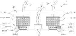
- this example of the robot hand 3 is equipped with a rectangular parallelepiped box-shaped support 10 (optional configuration), and a workpiece is fixed and gripped in this support 10. Two workpiece gripping parts 19 are provided.
- a liquid spraying section 16 (optional configuration) capable of spraying a liquid medium is provided between the two workpiece gripping sections 19.
- the shape, size, material, etc. of the support body 10 can be arbitrarily set as long as the work gripping part 19 and the liquid spraying part 16 can be installed or stored therein. As long as the workpiece gripping part 19 can be installed on the robot hand 3, it is not essential to provide the support body 10, and the support body 10 may be configured integrally with a part or all of the workpiece gripping part 19.
- the method of installation and storage on the support body 10 is also arbitrary, and it may be possible to fix it by fitting the workpiece gripping part 19 or the like, or to fix it together with a fixing tool such as a nut, bolt, or clamp as necessary.
- the workpiece gripping part 19 has a workpiece contacting part 15 that contacts the workpiece, and also includes a heating/cooling device 11 that can cool or heat the workpiece contacting part 15.
- the workpiece gripping section 19 generates an air layer (bubbles) that can serve as a heat insulating layer between the workpiece contact section 15 and the heating/cooling device 11 to promote heat transfer (that is, to maximize the heat transfer area).
- a thermal compound 14 is provided to minimize the As shown in FIG. 2, the thermal compound 14 is also provided on the upper surface side of the heating/cooling device 11, which is a side different from the workpiece contact portion 15 side, so that, for example, the heat dissipation effect to the upper surface side can be improved. can be increased.
- each work gripping part 19 is arranged at different positions on the robot hand 3 (support body 10), so that one workpiece gripping part 19 can be used in the procedure (transfer method) described later. Even when it is used for transferring a workpiece, any or all of the other workpiece gripping parts 19 can be pre-cooled or cooled to prepare for gripping the next workpiece, thereby reducing the waiting time. This reduces workpiece gripping and transfer, making workpiece gripping and transfer more efficient and faster.
- each work gripping part 19 is arranged near the end of the support 10 (approximately at the end).
- the workpiece gripping parts 19 are preferably arranged at regular intervals on the robot hand 3 and the support body 10, and more preferably, when viewed from the bottom side of the robot hand 3 (bottom view: FIG. 2). It is preferable that the work gripping parts 19 are arranged approximately evenly in the center of the robot hand 3 and the support body 10. By arranging the workpiece gripping section 19 in this way, the degree of freedom of movement of the robot hand (rotation and parallel motion) is increased, and each operation of gripping and transferring the workpiece and its cycle can be made more efficient. can. In addition, contact and interference between workpieces can be prevented.
- the liquid medium always adheres to the workpiece contact portion 15 in a liquid state or solidified (ice) state, so during continuous use, cleaning of the adhered material ( In some cases, it may be necessary to take measures such as wiping (wiping) or drying, so it is preferable to provide a plurality of work gripping parts 19. It is more preferable that three or more workpiece gripping parts 19 are arranged, and it is preferable that the number is determined as appropriate depending on the actual work or site.
- the shape and size of the workpiece contact portion 15 that comes into contact with the workpiece can be appropriately selected and determined according to the shape and size of the workpiece.
- the shape may be a flat plate, a disc, a polygonal flat, a curved surface, a sphere, an ellipsoid, a cone, or the like.
- the thickness is preferably 2 mm or less, more preferably 1 mm or less.
- the thickness is preferably 0.3 mm or more.
- a heating/cooling device 11 for cooling or heating the workpiece contacting part 15 is provided on the upper surface side of the workpiece contacting part 15.
- the heating/cooling device 11 is not limited as long as it can achieve the purpose, but it is preferable to use a Peltier device, for example, since it is advantageous in terms of space saving and high-speed response.
- a Peltier element is a semiconductor element that can generate thermal energy (temperature difference) when energized.Based on its principle, when energized, heat is absorbed from one surface, and heat is radiated from the other surface. will be able to cool down. If the direction in which the Peltier element is energized is reversed, the surfaces where heat absorption and heat radiation occur can be switched.
- the number and size (area) of the elements are selected appropriately depending on the shape, size, weight, and other characteristics of the workpiece [softness, surface condition (roughness, moisture, etc.)]. be able to.
- the workpiece contacting part 15 on the cooling surface side has the ability to be cooled down to -5°C or less within 10 seconds after electricity is applied. It is preferable that the type and arrangement of the elements be configured.
- the heating/cooling device 11 is not limited to the Peltier device as long as it can perform the same function as the Peltier device described above and achieve the object of the present invention.
- the workpiece contacting part 15 adjacent to the heating and cooling device 11 (including cases where other inclusions are included) is cooled to achieve cooling solidification and fixation (gripping) with the workpiece, and after transfer, the workpiece contacting part 15 is cooled. It is sufficient if the workpiece can be released by heating it.
- a vapor compression refrigerator type, heat pump type, or absorption type refrigerator heat exchanger can be used. It is arranged to conduct heat and pre-cool the workpiece contact area.
- a heat transfer device may also be installed on the heating surface of the heating/cooling device 11 for use during melting.
- a thermal compound 14 may be provided between the workpiece contact portion 15 and the heating/cooling device 11 in order to promote and improve heat conduction between them.
- the thermal compound 14 for example, one having a thermal conductivity of 0.5 W/m ⁇ K or more is suitable, and more preferably a thermal conductivity of 0.9 W/m ⁇ K or more.
- the type of thermal compound 14 is not limited as long as it does not impede the purpose, but in order to suppress the formation of a partial air gap or bubble layer within the contact surface, compositions such as grease or paste, or semi-cured products thereof may be used. It is preferable to use a cured product or the like. In particular, silicone grease for thermal conduction, flux for brazing, etc. can be used.
- a heat dissipation device such as an air cooling fan 13 may be provided together with the cooling fan 13.
- the heat sink 12 and the air cooling fan 13 publicly known ones can be appropriately selected and employed.
- the heat sink 12 for example, a plate fin type, a square pin fin type, a round pin fin type, a spray fin type, etc. can be used.
- the air cooling fan 13 for example, an axial fan, a centrifugal fan, a blower fan, etc. can be used.
- These heat dissipation devices are designed to have a thermal resistance of 20°C/W or less in order to ensure the cooling response of the workpiece contact area (cooling speed is slow, cooling temperature does not drop completely). It is preferable to adopt it as appropriate, and more preferably the thermal resistance is 10°C/W or less, but the load capacity of the robot hand 3 (robot transfer device 2) used and the heating used It can be selected and determined as appropriate depending on the cooling device 11.
- the installation positions of these heat dissipation devices are not limited to those shown in FIG. 2, and can be changed as appropriate. For example, it is preferable to install the air cooling fan 13 on the side of the heat sink 12 instead of on the top surface, since the heat exchange surface such as fins on the heat sink 12 can be effectively used.
- the robot hand 3 may be provided with a liquid spraying section 16 at an arbitrary position for spraying a liquid medium onto the workpiece 8 before being transferred.
- the liquid spraying section 16 is provided in the robot hand 3, it is preferably arranged near the middle (center) of each workpiece gripping section 19 from the viewpoint of efficiency of spraying the liquid onto the workpiece.
- the liquid spraying unit 16 is supplied with a cable for sending signals, etc. for energization or synchronization with the operation of the robot hand (robot transfer device 2), and a medium such as a liquid medium or air. (these are collectively referred to as the "supply line 18") are connected to the medium supply pipe for this purpose.
- a valve (such as a solenoid valve) for inlet and outlet of the medium may be provided.
- the liquid medium is one that is solidified (frozen) by cooling and can be fixed and gripped between the workpiece 8 and the workpiece contact portion 15 before being transferred, and the solidified (frozen) portion is heated by heating after transfer.
- the solidified (frozen) portion is heated by heating after transfer.
- a liquid medium containing a mixture of can be used. It may also be one whose freezing point is adjusted to be high.
- the freezing point in this case is not limited, but is preferably in the range of 0°C to 10°C. Low viscosity is preferred to prevent nozzle clogging during spraying. From the viewpoints of coagulability, versatility, economic efficiency, etc., it is preferable to use water or a food solution.
- any known liquid spraying means can be employed without limitation, and any means that can spray a liquid medium using a one-fluid type, two-fluid type, ultrasonic type, or the like may be used.
- a sprayer spray nozzle
- a two-fluid nozzle that can spray the liquid medium and compressed air is preferably used, which enables uniform spraying onto the workpiece.
- an appropriate amount (minimum necessary) of the liquid medium can be applied to the surface of the workpiece, and excessive spraying can be prevented.
- fine spraying allows the liquid medium to be sprayed only on the surface of the textile product, preventing liquid from staining the back side of the textile product due to excessive spraying.
- the amount of spraying can be appropriately set depending on the workpiece to be used and the degree of cooling and solidification with the workpiece.
- the liquid spraying section 16 does not need to be provided as the robot hand 3, and may be provided near the workpiece 8 before being transferred in the robot transfer system 1. It is only necessary to provide a means that can spray a liquid medium onto the workpiece 8 before being transferred before contacting with the previous workpiece contacting section 15 . As described above, in such a case, the liquid spray section 16 is preferably disposed substantially directly above the work 8 before being transferred, in order to improve the efficiency of spraying the liquid medium onto the work. On the other hand, when there is moisture adhering to the surface of the workpiece (e.g. food with a lot of water) or the workpiece has already been frozen (e.g. frozen food or processed food), the forced liquid medium may be For manufacturing processes that do not require spraying, the liquid spraying section 16 may not be provided.
- the liquid spraying section 16 may not be provided.
- FIG. 4 is a diagram schematically showing the robot hand 3 according to Embodiment 2 of the present invention, and is a plan view viewed from directly below (bottom view) as in the case of FIG. 2 described above.
- FIG. 5 is a side view when viewed from the direction of the white arrow in FIG. 4.
- the liquid spraying part 16 is shown slightly to the right, but this is to avoid overlapping with the work gripping part 19 that is visible on the back side of the liquid spraying part 16.
- the support body 10 is branched into three parts, and the tip (substantially the end) of each branch part has the above-mentioned A similar work gripping section 19 is mounted.
- the configuration of the workpiece gripping section 19 may be the same as that of the first embodiment described above. That is, in the second embodiment, the support body 10 is divided approximately equally so as to correspond to each vertex of the equilateral triangle, and the workpiece is gripped approximately evenly with respect to the center of the support body 10. Section 19 is arranged. Further, as shown in the broken line in FIG. 4 and in FIG. Since the three workpiece gripping parts 19 are rotatable about 20, the operation in gripping and transferring the workpieces can be made more efficient.
- the support body 10 may have a branched structure having four or more tips (ends), such as a square, a regular pentagon, or a regular hexagon. It is also possible to configure substantially uniform tips (ends) to be located at each vertex of a (regular) polygon such as This is preferable because it can be arranged approximately evenly in 10.
- one or more of the work grip parts 19 can be used for standby or maintenance. Since it can also be used for purposes such as cleaning, etc., it is possible to more efficiently grip and transfer workpieces without interrupting operations as much as possible.
- the robot hand 3 of the second embodiment has a liquid spraying section 16 near the center of the lower surface of the support 10, as shown in FIG. It is preferable to arrange the liquid spraying section 16 near the center of the lower surface of the support 10 because it is possible to construct the shortest path for moving from the spraying step to the transfer step.
- the position of the liquid spray section 16 is not limited to this.
- the structure of the liquid spray section 16 is the same as that of the first embodiment described above, and the structure and arrangement can be changed as appropriate.
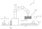
- the robot transfer device 2 equipped with the robot hand 3 according to the embodiment described above is used. Further, in the robot transfer system 1 using such a robot transfer device 2, a workpiece is transferred from a workpiece transfer source 6 to a workpiece transfer destination 9.
- the workpiece transfer method according to the embodiment of the present invention is characterized by having at least the following steps/steps i) to vi), although they are not limited to them. The description will be made using the reference numerals in FIGS. 1 to 5 as appropriate.
- the surface of the workpiece contact portion 15 be at -5°C or lower, and preferably at -8°C or lower. More preferably, the temperature is ⁇ 10° C. or less. Although there is no limit to the lower limit of the temperature, it is generally preferable to set the temperature to -15° C. or higher to avoid overcooling as much as possible. When handling a workpiece with moisture attached at room temperature, it is preferable to keep the temperature of the workpiece contact portion 15 at about -8°C to -10°C.
- the time required for this can be adjusted as appropriate by taking into consideration the performance (cooling performance, heat dissipation performance, etc.) of the heating and cooling device 11, the material and thickness of the thermal compound 14 and/or the workpiece contact part 15, etc.
- the time is within one minute, more preferably within 30 seconds, and even more preferably within 20 seconds.
- the work 8 to which the liquid medium as described above has been attached is used as the work 8 before being transferred to be gripped by the work gripping part 19 (work contact part 15) that has been precooled or cooled in step i). It has a step of preparing. Normally, for a workpiece whose surface does not have moisture attached to it, the liquid medium is sprayed onto the surface of the workpiece 8 by spraying the liquid medium from the liquid spraying section 16 provided inside and outside the robot hand 3.
- the time required for such adhesion (spraying) of the liquid medium to the workpiece 8 depends on the size, shape, surface characteristics (hydrophilicity/hydrophobicity, surface roughness, etc.) of the workpiece, and the arrangement of equipment during the process. Although it may vary depending on the situation, in order to improve the efficiency of work transfer, it is preferable that the time is within 1 minute, more preferably within 30 seconds, and even more preferably within 20 seconds. This time includes the time required to bring the workpiece 8 close to the liquid spraying section 16, but this time is usually preferably within 10 seconds, and more preferably within 5 seconds.
- the time required to complete cooling and solidification (freezing) of such a contact area is preferably within 20 seconds, more preferably within 10 seconds, in order to improve the efficiency of workpiece transfer. More preferably, the time is within 5 seconds.
- the robot hand includes a plurality of workpiece gripping parts 19 (workpiece contact parts 15).
- the workpiece transfer method according to the embodiment of the present invention is characterized in that the plurality of workpiece gripping parts 19 (workpiece contact parts 15) are utilized to improve the efficiency of workpiece gripping and transfer. That is, as step iv), one of the other workpiece gripping parts 19 (workpiece contacting part 15) used subsequent to the workpiece gripping part 19 (workpiece contacting part 15) used in the steps i) to iii) above.
- there is a step of pre-cooling or cooling each workpiece contact portion by energizing and operating the respective heating and cooling devices 11 provided in the plurality of devices.
- the timing of pre-cooling/cooling the other workpiece contacting parts 15 may be at the same time as step i), or may be later than that, depending on the preparation status of the next workpiece and the gripping thereof. This can be determined as appropriate depending on the timing of transfer. In order to improve the efficiency of workpiece transfer, the cooling of these (other) workpiece contacting parts 15 must be completed without undue delay in pre-cooling or cooling of the workpiece contacting parts 15 that have been used from the beginning. Preferably, the timing may be the same as the pre-cooling or cooling of the workpiece contacting portion 15 used from the beginning.
- step v) Following step iii), the workpiece 8' gripped and fixed to the workpiece contact portion 15 used from the beginning is transferred to the transfer destination 9.
- the workpieces are transferred by suitable means according to the process by controlling the movements of the robot (robot arm) 4 and robot hand 3 by their respective controllers.
- Heating of the workpiece contact portion 15 is performed by energizing the heating and cooling device 11. That is, for example, when a Peltier element is used, the cooling surface and the heating surface can be exchanged by energizing the heating/cooling device 11 in a different direction (in the opposite direction) than in step i) above. , Therefore, heat is conducted to the workpiece contacting portion 15 side, which has been used in a cooled state, and is heated. Further, when a refrigeration cycle is used as the heating/cooling device 11, it is preferable that the workpiece contact portion 15 is heated by utilizing the released heat generated by liquefying and condensing the refrigerant gas.
- the contact portion (fixed portion) between the workpiece 8' and the workpiece contact portion 15 is melted in a relatively short time.
- the fixed portion can be melted in a relatively short time while suppressing excessive heating.
- the time required for melting is preferably within 20 seconds, more preferably within 10 seconds, even more preferably within 5 seconds, in order to improve the efficiency of transferring the workpiece.
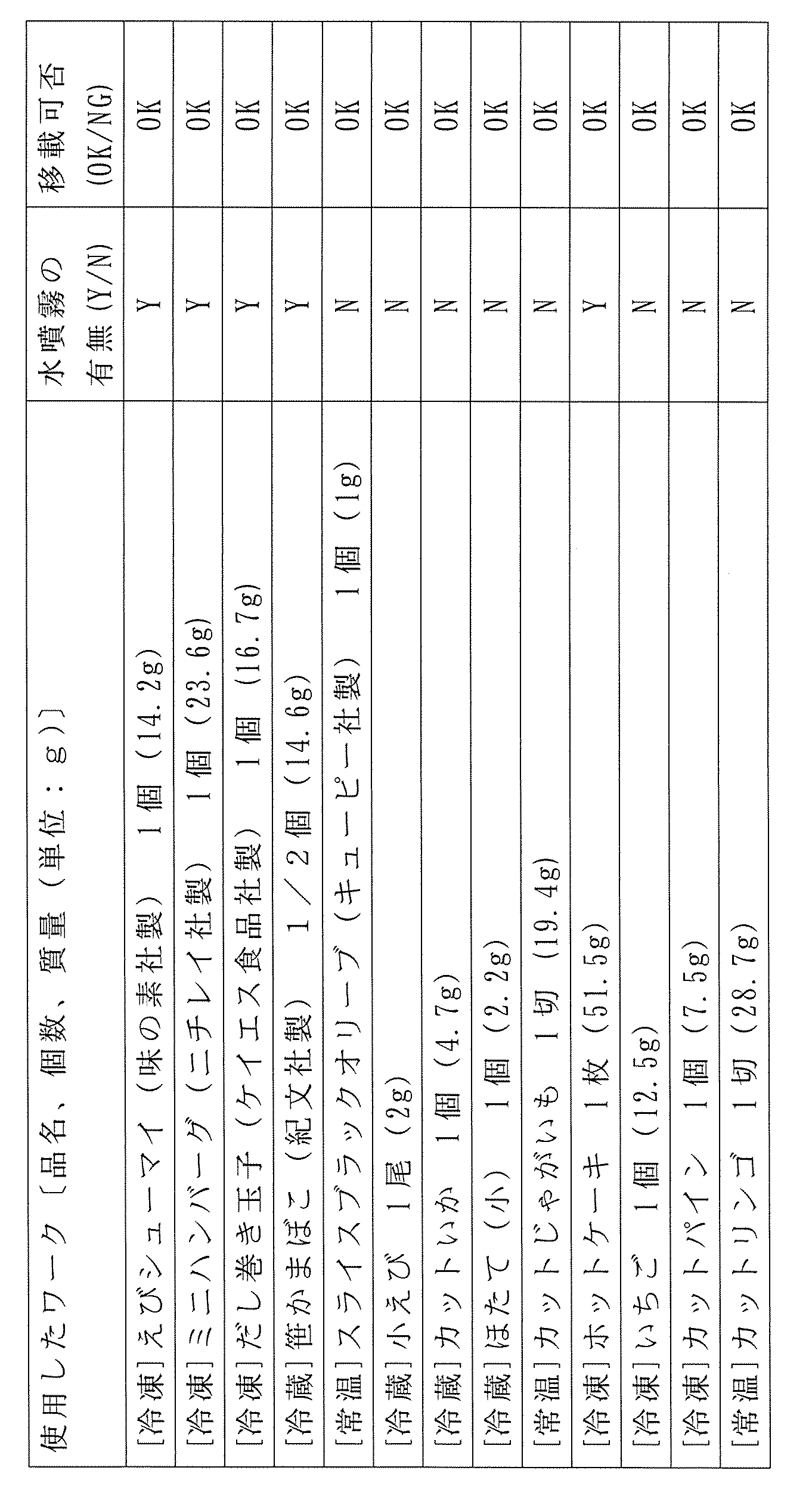
- the workpiece gripping unit 15 For each workpiece with or without water attached, the workpiece gripping unit 15, which is ready for cooling, is pressed against the top surface of the workpiece, held for 1 to 3 seconds, and then the robot arm is operated to grip each workpiece. and lifted it (for about 1 second). For the workpieces that could be lifted for 10 seconds, the transferability was indicated as "OK”. On the other hand, for workpieces that could not be grasped or lifted, the transferability was evaluated as "NG”. The results are shown in Table 1.
- Robot transfer system 2... Robot transfer device, 3... Robot hand, 4... Robot (robot arm), 5... Controller, 6... Transfer source, 7... Conveyor, 8, 8', 8''... Workpiece, 9...Transfer destination, 10...Support, 11...Heating/cooling device, 12...Heat sink, 13...Air cooling fan, 14...Thermal compound, 15...Work contact part, 16...Liquid spray part, 17...Cable, 18 ... Supply line, 19... Work gripping section, 20... Connection section
Landscapes
- Engineering & Computer Science (AREA)
- Mechanical Engineering (AREA)
- Robotics (AREA)
- Manipulator (AREA)
Abstract
Description
[1]ワークを固着させて把持するワーク把持部を有するロボットハンドであって、
前記ワーク把持部は、少なくとも、ワークに接触するワーク接触部と、当該ワーク接触部を加熱又は冷却する加熱冷却装置とを備え、
当該ロボットハンドにおいて、前記ワーク把持部は、それぞれ異なる位置に分かれて2つ以上配されることを特徴とするロボットハンド。
[2]前記異なる位置に分かれて2つ以上配されるワーク把持部において、1つのワーク把持部の使用時には、それ以外のワーク把持部のいずれか又は全部が前記加熱冷却装置により予冷ないし冷却されていることを特徴とする[1]に記載のロボットハンド。
[3]前記ワーク把持部を取り付ける支持体を有し、ワーク把持部が当該支持体の略端部にそれぞれ配されることを特徴する[1]に記載のロボットハンド。
[4]前記ワーク把持部が、下面視において、前記支持体の中心部に対して略均等に配置されることを特徴とする[3]の記載の当該ロボットハンド。
[5]前記ワーク把持部を3つ以上有することを特徴する[1]に記載のロボットハンド。
[6]凍結と融解とが可能な液状媒体を噴霧する液噴霧部を有することを特徴とする[1]に記載のロボットハンド。
[7]前記加熱冷却装置は、ペルチエ素子又は熱交換器を有することを特徴とする[1]に記載のロボットハンド。
[8]前記加熱冷却装置と前記ワーク接触部との間に、サーマルコンパウンドを有することを特徴とする[1]に記載のロボットハンド。
[9]前記[1]~[8]のいずれかに記載のロボットハンドが搭載されてなり、前記ワーク把持部に把持されたワークを移載元から移載先に移載できるロボット移載装置。
[10]少なくとも、[9]に記載のロボット移載装置と、ワーク移載元と、ワーク移載先とを有することを特徴とするロボット移載システム。
[11]凍結と融解とが可能な液状媒体を噴霧する液噴霧部を、前記ワーク移載元の近傍に備えることを特徴とする[10]に記載のロボット移載システム。
[12]前記[10]又は[11]に記載のロボット移載システムを用いて、移載元から移載先にワークを移載する方法であって、少なくとも次のi)~vi)の段階;
i)加熱冷却装置に通電して作動させて、ワーク把持部におけるワーク接触部の少なくとも1つを予冷する段階と、
ii)液状媒体が付着した移載元のワークを準備する段階と、
iii)液状媒体が付着したワーク表面に、前記予冷によって冷却された少なくとも1つのワーク接触部を接触させて、前記液状媒体の冷却固化を通じてワークとワーク接触部とを固着させる段階と、
iv)前記i)~iii)の段階で使用したワーク把持部以外の他のワーク把持部における加熱冷却装置に通電して作動させて、当該他のワーク把持部におけるワーク接触部の少なくとも1つを予冷する段階と、
v)前記iii)の段階で固着されたワークを把持して移載先に移載する段階と、
vi)前記v)の段階で移載に用いられたワーク把持部のワーク接触部における加熱冷却装置に通電して作動させ、当該ワーク接触部を加熱してワークとの固着部を融解させてワークを解放する段階と
を有することを特徴とするワーク移載方法。
[13]前記v)の段階から前記vi)の段階のいずれかにおいて、前記iv)の段階の予冷によって冷却された他のワーク把持部におけるワーク接触部の少なくとも1つを用いて、次に移載する移載元のワークに対して、前記ii)、iii)、v)及びvi)の段階を順次実施することを特徴する[12]に記載のワーク移載方法。
[14]前記[12]又は[13]に記載のワーク移載方法を複数サイクル行って、ワーク移載元からワーク移載先にワークを移載することを特徴とするワーク移載方法。
図1には、本発明の実施形態のロボット移載システム(符号:1。以下、数字のみを表記する。)の全体的な概略を例示的に示した全体模式図である。すなわち、本発明の実施形態のロボット移載システム1は、図1に示したように、少なくとも、a)ロボット(ロボットアーム)4の先端等に、ロボットハンド3が搭載されたロボット移載装置2と、b)移載前のワーク8が存在する移載元6と、(c)ロボット移載装置2のロボットハンド3へのワーク(ワーク8’)の把持や移載を通じて、移載した後のワーク8’’の配置や格納等のための移載先9とを有する。とくに移載元6と移載先9とは、実際の作業や現場毎に、それに適した配置や構成とすることが好ましい。
本発明の実施形態のロボットハンド3は、ワークを把持して移載元から移載先に移載している間、ワークが把持された状態を継続でき、尚且つ、移載先においてワークを手放す(解放する)ことができるものであればよい。それ以外の付加的な作用を発現できる装置構成となってもよい。ここで、ワークの「把持」については、移載元においてワークを取り出す(持ち上げる)ことができればよく、ワークを掴む、握る、摘む、掬う、載せる等のような公知の機械的な動作を任意に含むことができ、さらに、接着や吸着等の物理化学的な作用も任意に含むことができるが、後述する冷却固化の作用を発現する手段を必須として備えるようにする。
図2は、本発明の実施の形態1に係るロボットハンド3を模式的に表した図であり、図1に示したロボットハンド3を真下から視認(下面視)した平面図である。また、図3は、図2のA-A断面における断面図である。つまり、図3を真下から視認(下面視)した場合の平面図が図2である。
なお、ワーク接触部15には、ワークとの固着・把持を補助するためのその他の補助機構(真空バキューム、弱い粘着・接着、静電気など)や、ワークを手放す際のその他の補助機構(振動、押し出し、加圧等)を備えてもよい。
図4は、本発明の実施の形態2に係るロボットハンド3を模式的に表した図であり、前記の図2の場合と同様に、真下から視認(下面視)した平面図である。また、図5は、図4中の白矢印方向から視認した際の側面図である。図5においては、液噴霧部16をやや右よりに記載したが、液噴霧部16の裏側に視認されるワーク把持部19との重複を回避するためである。
すなわち、この実施の形態2においては、このように支持体10が正三角形状の各頂点に対応するように略均等に分かれており、支持体10の中心部に対して、略均等にワーク把持部19が配されている。また、図4の破線及び図5に示されるとおり、支持体10の中心部には連結部20としての回転可能な回転軸又は軸受け(任意構成)を備えてもよく、これにより、当該連結部20を中心として3つのワーク把持部19が回転可能となることから、ワークの把持や移載において動作を効率化できる。
そして、本発明の実施形態においては、前記のような実施の形態に係るロボットハンド3を備えたロボット移載装置2が用いられる。また、そのようなロボット移載装置2を用いたロボット移載システム1において、ワークの移載元6からワークの移載先9へ、ワークを移載させる。本発明の実施形態のワーク移載方法は、限定されるものではないが、少なくとも次の手順・段階i)~vi)を有することを特徴とする。適宜、図1~図5の符合を用いて説明する。
すなわち、本発明の実施形態のワーク移載方法には、先ずi)の段階として、最初に使用するワーク把持部19における加熱冷却装置11に通電して作動させて、ワーク把持部15側が冷却されるように準備(予冷)を行う段階を有する。これにより、必要に応じて設置されるサーマルコンパウンド14を通じて、加熱冷却装置11からワーク接触部15に熱伝導が起こり、ワーク接触部15の表面が一定の温度に冷却されるまで継続される。
次に、前記i)の段階で予冷ないし冷却が行われたワーク把持部19(ワーク接触部15)に把持される移載前のワーク8として、前記のような液状媒体が付着されたワーク8を準備する段階を有する。通常、表面に水分などが付着していないワークに対しては、ロボットハンド3の内外に設けられる前記液噴霧部16からの液状媒体の噴霧により、ワーク8の表面に液状媒体を付着させる。
次に、前記i)の段階で冷却が行われたワーク把持部19(ワーク接触部15)を、前記ii)の段階で液状媒体が付着したワーク8の表面に接触させて、前記液状媒体の冷却固化を通じて、ワーク8とワーク接触部15とを固着させる段階を有する。当該接触に際しては、その方法は制限されないが、ワーク接触部15に対して液状媒体が十分に接触することが好ましく、例えば、ロボットの加圧値をフィードバックするコンプライアンス制御を用いて接触の程度が調整されることが好ましい。そして、当該接触部における液状媒体の十分な冷却固化(凍結)の把握には、例えば、ワーク把持前後の重量を重さセンサーでモニタリング計測することが可能である。このような接触部の冷却固化(凍結)の完了に要する時間としては、ワークの移載の効率化のためには、20秒以内となるようにすることが好ましく、より好ましくは10秒以内、さらに好ましくは5秒以内がよい。
前述のとおり、本発明の実施形態のロボットハンドは、複数のワーク把持部19(ワーク接触部15)を備える。ここで、本発明の実施形態のワーク移載方法においては、この複数のワーク把持部19(ワーク接触部15)を活用して、ワークの把持や移載を効率化することを特徴として有する。すなわち、段階iv)として、前記i)~iii)の段階で使用されたワーク把持部19(ワーク接触部15)に引き続いて使用される他のワーク把持部19(ワーク接触部15)の1つまたは複数に対して、それ(ら)に備えられるそれぞれの加熱冷却装置11に通電して作動させて、各ワーク接触部の予冷ないし冷却を行う段階を有する。
前記iii)の段階に引き続き、最初から使用したワーク接触部15に把持・固着されたワーク8’を移載先9に移載する。この段階v)の手段については制限が無いが、ロボット(ロボットアーム)4やロボットハンド3の動作をそれぞれのコントローラによる制御により、工程に合わせて好適な手段でワークを移載させる。
そして、段階v)により移載先9に移載されたワーク8’に対して、ワーク接触部15を加熱することにより、ワーク8’とワーク接触部15との接触部(固着部)を融解させて、ワークを手放す(解放する)。それにより、移載されたワーク8’’が移載先9に配置される。
デンソーウェーブ社の6軸ロボットCOBOTTA(コボッタ)を、ロボット(ロボットアーム)4として用いた。このロボット(ロボットアーム)4の先端に、空冷ファン13の配置を除いて図2~3に示された各構成及び配置を備えるロボットハンド3を取り付けて、本発明の実施形態のロボット移載装置2とした。空冷ファン13の配置は後述のとおりとした。ロボットハンド3の具体的な構成は、以下のとおりである。
4か所のネジ締結部を介してロボット(ロボットアーム)4へのロボットハンド3の先端固定を行った。
縦96mm×横150mm×高さ53mmから成る直方体の箱型状のPLA樹脂製のケースを用いた。下面視で、当該ケースの横方向のそれぞれの略端部〔ケース横方向の各末端部から25mmの位置〕のそれぞれに2つのワーク接触部15の中心部が来るように、ワーク把持部19が設置されるようにした。ケース内へのワーク把持部19の設置・格納は、ヒートシンク12の側面を支持体10との固定部へのネジ締結(4か所)を介して行った。空冷ファン13は、ヒートシンク12の真横に配置されるように、支持体10との固定部へのネジ締結を介して設置した。
2cm角の銅板(0.3mm厚み)を用いた。
サンハヤト社製のSCV-22(放熱用シリコーン)を用いた。このサーマルコンパウンド14を約1~2mL準備し、ペルチエ素子11とワーク接触部15との間に塗布し、厚みが0.1mm程度になるように硬化させた。また、ペルチエ素子11の上面側のヒートシンク12との間にも介在させた。
秋月電子通商 型番:TEC-40865A-00を用いた。
SeeedStudio製、型番:114992082を用いた。
(包絡体積からの熱抵抗値:約7℃/W)
山洋電気製、型番:109P0405J601を用いた。
2流体式の噴霧ノズル(アネスト岩田製、エコノズルEN-2)を用いた。この噴霧ノズルに0.5MPaの圧縮エアーと水とをつなぎ、液噴霧において、空圧0.1MPaを上限としたレギュレーターと、NC電磁弁を用い、制御ユニットからの信号と同期させた。制御ユニットとしては、AE-ATMEGA-328 MINI、PICマイコン(MICROCHIP TECHNOLOGY社製、型番:PIC16F18857T-I/SO)、およびイーサネットコントローラ(MICROCHIP TECHNOLOGY社製、ENC28J60)、から成る。液噴霧直とロボット(ロボットアーム)4の動作とが同期するように出力信号を調節した。
液噴霧部16は、支持体10の下面中央部にねじ固定で設置した。ワーク8の直上に移動した直後に噴霧し、その後噴霧したワークに対して、ワーク把持部19(ワーク接触部15)が直上から接触するようにプログラムを生成し、動かした。
そして、上記の構成を有する本発明の実施形態のロボット移載装置2を用いて、下記の表1に示した各ワークの移載が実現できるかどうかを確認した。先ず、ロボットハンド3における前記ペルチエ素子11の1つに対して、コントローラからの指示信号を送り通電を行い、当該ワーク接触部15の予冷ないし冷却を行った。約20秒後にはワーク接触部15がマイナス8℃~マイナス10℃程度になったことを確認した。ワークの一部には、その上面に対して水を最大数秒程度噴霧し、ワーク上面に水の膜ができる程度に濡らしたが(水噴霧:Y)、一部のワークには水の噴霧を行わなかった(水噴霧:N)。水が付着された又はされない各ワークに対して、冷却準備が完了したワーク把持部15をワーク上面に押し当て、1~3秒間保持したあとに、ロボットアームの部分を動作させて各ワークを把持して持ち上げた(約1秒間)。そして、10秒間持ち上げができたワークについては、移載可否を「OK」として示した。他方、ワークの把持・持ち上げができないものについては、移載可否を「NG」として評価した。
結果を表1に示す。
Claims (14)
- ワークを固着させて把持するワーク把持部を有するロボットハンドであって、
前記ワーク把持部は、少なくとも、ワークに接触するワーク接触部と、当該ワーク接触部を加熱又は冷却する加熱冷却装置とを備え、
当該ロボットハンドにおいて、前記ワーク把持部は、それぞれ異なる位置に分かれて2つ以上配されることを特徴とするロボットハンド。 - 前記異なる位置に分かれて2つ以上配されるワーク把持部において、1つのワーク把持部の使用時には、それ以外のワーク把持部のいずれか又は全部が前記加熱冷却装置により予冷ないし冷却されていることを特徴とする請求項1に記載のロボットハンド。
- 前記ワーク把持部を取り付ける支持体を有し、ワーク把持部が当該支持体の略端部にそれぞれ配されることを特徴する請求項1に記載のロボットハンド。
- 前記ワーク把持部が、下面視において、前記支持体の中心部に対して略均等に配置されることを特徴とする請求項3の記載の当該ロボットハンド。
- 前記ワーク把持部を3つ以上有することを特徴する請求項1に記載のロボットハンド。
- 凍結と融解とが可能な液状媒体を噴霧する液噴霧部を有することを特徴とする請求項1に記載のロボットハンド。
- 前記加熱冷却装置は、ペルチエ素子又は熱交換器を有することを特徴とする請求項1に記載のロボットハンド。
- 前記加熱冷却装置と前記ワーク接触部との間に、サーマルコンパウンドを有することを特徴とする請求項1に記載のロボットハンド。
- 請求項1~8のいずれかに記載のロボットハンドが搭載されてなり、前記ワーク把持部に把持されたワークを移載元から移載先に移載できるロボット移載装置。
- 少なくとも、請求項9に記載のロボット移載装置と、ワーク移載元と、ワーク移載先とを有することを特徴とするロボット移載システム。
- 凍結と融解とが可能な液状媒体を噴霧する液噴霧部を、前記ワーク移載元の近傍に備えることを特徴とする請求項10に記載のロボット移載システム。
- 請求項10又は11に記載のロボット移載システムを用いて、移載元から移載先にワークを移載する方法であって、少なくとも次のi)~vi)の段階;
i)加熱冷却装置に通電して作動させて、ワーク把持部におけるワーク接触部の少なくとも1つを予冷する段階と、
ii)液状媒体が付着した移載元のワークを準備する段階と、
iii)液状媒体が付着したワーク表面に、前記予冷によって冷却された少なくとも1つのワーク接触部を接触させて、前記液状媒体の冷却固化を通じてワークとワーク接触部とを固着させる段階と、
iv)前記i)~iii)の段階で使用したワーク把持部以外の他のワーク把持部における加熱冷却装置に通電して作動させて、当該他のワーク把持部におけるワーク接触部の少なくとも1つを予冷する段階と、
v)前記iii)の段階で固着されたワークを把持して移載先に移載する段階と、
vi)前記v)の段階で移載に用いられたワーク把持部のワーク接触部における加熱冷却装置に通電して作動させ、当該ワーク接触部を加熱してワークとの固着部を融解させてワークを解放する段階と
を有することを特徴とするワーク移載方法。 - 前記v)の段階から前記vi)の段階のいずれかにおいて、前記iv)の段階の予冷によって冷却された他のワーク把持部におけるワーク接触部の少なくとも1つを用いて、次に移載する移載元のワークに対して、前記ii)、iii)、v)及びvi)の段階を順次実施することを特徴する請求項12に記載のワーク移載方法。
- 請求項12又は請求項13に記載のワーク移載方法を複数サイクル行って、ワーク移載元からワーク移載先にワークを移載することを特徴とするワーク移載方法。
Priority Applications (2)
| Application Number | Priority Date | Filing Date | Title |
|---|---|---|---|
| JP2024528739A JPWO2023248778A1 (ja) | 2022-06-20 | 2023-06-06 | |
| CN202380036363.8A CN119095701A (zh) | 2022-06-20 | 2023-06-06 | 机器人手臂与使用所述手臂的机器人搬运装置、机器人搬运系统以及工件搬运方法 |
Applications Claiming Priority (2)
| Application Number | Priority Date | Filing Date | Title |
|---|---|---|---|
| JP2022099064 | 2022-06-20 | ||
| JP2022-099064 | 2022-06-20 |
Publications (1)
| Publication Number | Publication Date |
|---|---|
| WO2023248778A1 true WO2023248778A1 (ja) | 2023-12-28 |
Family
ID=89379654
Family Applications (1)
| Application Number | Title | Priority Date | Filing Date |
|---|---|---|---|
| PCT/JP2023/020936 Ceased WO2023248778A1 (ja) | 2022-06-20 | 2023-06-06 | ロボットハンド並びにそれを用いたロボット移載装置、ロボット移載システム及びワーク移載方法 |
Country Status (4)
| Country | Link |
|---|---|
| JP (1) | JPWO2023248778A1 (ja) |
| CN (1) | CN119095701A (ja) |
| TW (1) | TW202413250A (ja) |
| WO (1) | WO2023248778A1 (ja) |
Citations (5)
| Publication number | Priority date | Publication date | Assignee | Title |
|---|---|---|---|---|
| JPH02188326A (ja) * | 1988-10-18 | 1990-07-24 | Pfaff Ind Gmbh | 裁断材を個別化し、搬送し、降ろすための装置 |
| JP2008028318A (ja) * | 2006-07-25 | 2008-02-07 | Fujikoshi Mach Corp | 半導体ウェーハの搬送装置および搬送方法 |
| JP2008072099A (ja) * | 2006-08-14 | 2008-03-27 | Qimonda Ag | 半導体形成工程において部材を取り扱うための方法および装置 |
| JP2008117844A (ja) * | 2006-11-01 | 2008-05-22 | Disco Abrasive Syst Ltd | ウエーハの搬送方法および加工装置 |
| JP2008517623A (ja) * | 2004-10-29 | 2008-05-29 | シンベント アクティーゼルスカブ | 湿った製品を取り扱う装置と方法 |
-
2023
- 2023-06-06 WO PCT/JP2023/020936 patent/WO2023248778A1/ja not_active Ceased
- 2023-06-06 JP JP2024528739A patent/JPWO2023248778A1/ja active Pending
- 2023-06-06 CN CN202380036363.8A patent/CN119095701A/zh active Pending
- 2023-06-13 TW TW112121914A patent/TW202413250A/zh unknown
Patent Citations (5)
| Publication number | Priority date | Publication date | Assignee | Title |
|---|---|---|---|---|
| JPH02188326A (ja) * | 1988-10-18 | 1990-07-24 | Pfaff Ind Gmbh | 裁断材を個別化し、搬送し、降ろすための装置 |
| JP2008517623A (ja) * | 2004-10-29 | 2008-05-29 | シンベント アクティーゼルスカブ | 湿った製品を取り扱う装置と方法 |
| JP2008028318A (ja) * | 2006-07-25 | 2008-02-07 | Fujikoshi Mach Corp | 半導体ウェーハの搬送装置および搬送方法 |
| JP2008072099A (ja) * | 2006-08-14 | 2008-03-27 | Qimonda Ag | 半導体形成工程において部材を取り扱うための方法および装置 |
| JP2008117844A (ja) * | 2006-11-01 | 2008-05-22 | Disco Abrasive Syst Ltd | ウエーハの搬送方法および加工装置 |
Also Published As
| Publication number | Publication date |
|---|---|
| CN119095701A (zh) | 2024-12-06 |
| JPWO2023248778A1 (ja) | 2023-12-28 |
| TW202413250A (zh) | 2024-04-01 |
Similar Documents
| Publication | Publication Date | Title |
|---|---|---|
| CN108436952B (zh) | 一种电-气复合驱动柔性手指的仿鹰爪物流包装机械手 | |
| CN108214535B (zh) | 一种同步控制机械手 | |
| JP4026773B2 (ja) | 食材の把持移動方法及び装置 | |
| CN104690741B (zh) | 一种机械手末端执行器装置 | |
| EP1612005B1 (en) | Rotatable, squeeze-spread end effector for industrial robot | |
| TWI641536B (zh) | Food filling device | |
| JP6951106B2 (ja) | 食品保持装置およびその動作方法 | |
| CN102550215A (zh) | 一种多类型果蔬采摘的磁流变适型夹持器及机器人 | |
| JP6626411B2 (ja) | 食品の詰め込み装置 | |
| WO2023248778A1 (ja) | ロボットハンド並びにそれを用いたロボット移載装置、ロボット移載システム及びワーク移載方法 | |
| CN102090210A (zh) | 多果型果蔬采摘机器人的末端执行器及机器人 | |
| CN110494262A (zh) | 食品保持装置及其动作方法 | |
| CN221089055U (zh) | 一种宏动及微动结合的大气压晶圆输送机械手 | |
| HK40115284A (zh) | 机器人手臂与使用所述手臂的机器人搬运装置、机器人搬运系统以及工件搬运方法 | |
| CN104843496A (zh) | 一种纸箱码垛成型装置及方法 | |
| CN111086019A (zh) | 一种用于抓取圆柱形工件的气动-电磁混合控制机械手及其控制方法 | |
| CN104869840B (zh) | 用于优化冷冻模制产品的取出的方法 | |
| CN207726370U (zh) | 一种用于单双箱抓取的真空吸附式末端执行器 | |
| CN216027657U (zh) | 一种端拾器左右件冲压方向自动对称旋转机构 | |
| JPH03279112A (ja) | ハンドリングロボット | |
| US12075947B2 (en) | Automatic cooking systems | |
| CN209319809U (zh) | 机械手组件、机械手和机械设备 | |
| CN113401650A (zh) | 一种换热器翅片自动抓取夹具及系统 | |
| GB2232656A (en) | Article handling apparatus and methods | |
| CN208163677U (zh) | 一种化工产品用转运拿取组件 |
Legal Events
| Date | Code | Title | Description |
|---|---|---|---|
| 121 | Ep: the epo has been informed by wipo that ep was designated in this application |
Ref document number: 23826965 Country of ref document: EP Kind code of ref document: A1 |
|
| WWE | Wipo information: entry into national phase |
Ref document number: 2024528739 Country of ref document: JP |
|
| WWE | Wipo information: entry into national phase |
Ref document number: 202380036363.8 Country of ref document: CN |
|
| NENP | Non-entry into the national phase |
Ref country code: DE |
|
| 122 | Ep: pct application non-entry in european phase |
Ref document number: 23826965 Country of ref document: EP Kind code of ref document: A1 |