WO2023248650A1 - Welding method, can body manufacturing method, and welding device - Google Patents
Welding method, can body manufacturing method, and welding device Download PDFInfo
- Publication number
- WO2023248650A1 WO2023248650A1 PCT/JP2023/018311 JP2023018311W WO2023248650A1 WO 2023248650 A1 WO2023248650 A1 WO 2023248650A1 JP 2023018311 W JP2023018311 W JP 2023018311W WO 2023248650 A1 WO2023248650 A1 WO 2023248650A1
- Authority
- WO
- WIPO (PCT)
- Prior art keywords
- welding
- consumable electrode
- workpiece
- welded
- arc
- Prior art date
Links
- 238000003466 welding Methods 0.000 title claims abstract description 393
- 238000000034 method Methods 0.000 title claims abstract description 99
- 238000004519 manufacturing process Methods 0.000 title claims description 20
- 238000006073 displacement reaction Methods 0.000 claims description 24
- 238000001514 detection method Methods 0.000 claims description 13
- 230000002093 peripheral effect Effects 0.000 claims description 10
- 230000007246 mechanism Effects 0.000 claims description 5
- 238000002360 preparation method Methods 0.000 abstract description 7
- 239000007789 gas Substances 0.000 description 24
- 230000000694 effects Effects 0.000 description 16
- 238000010586 diagram Methods 0.000 description 15
- 239000000463 material Substances 0.000 description 11
- WFKWXMTUELFFGS-UHFFFAOYSA-N tungsten Chemical compound [W] WFKWXMTUELFFGS-UHFFFAOYSA-N 0.000 description 11
- 229910052721 tungsten Inorganic materials 0.000 description 11
- 239000010937 tungsten Substances 0.000 description 11
- 230000008859 change Effects 0.000 description 10
- 230000007547 defect Effects 0.000 description 10
- 210000001503 joint Anatomy 0.000 description 8
- 229910052751 metal Inorganic materials 0.000 description 8
- 239000002184 metal Substances 0.000 description 8
- 238000002474 experimental method Methods 0.000 description 6
- 238000005259 measurement Methods 0.000 description 6
- 239000011261 inert gas Substances 0.000 description 5
- 239000000155 melt Substances 0.000 description 5
- 238000005452 bending Methods 0.000 description 4
- RYGMFSIKBFXOCR-UHFFFAOYSA-N Copper Chemical compound [Cu] RYGMFSIKBFXOCR-UHFFFAOYSA-N 0.000 description 3
- 229910052802 copper Inorganic materials 0.000 description 3
- 239000010949 copper Substances 0.000 description 3
- 230000004048 modification Effects 0.000 description 3
- 238000012986 modification Methods 0.000 description 3
- 238000010998 test method Methods 0.000 description 3
- XLYOFNOQVPJJNP-UHFFFAOYSA-N water Substances O XLYOFNOQVPJJNP-UHFFFAOYSA-N 0.000 description 3
- XKRFYHLGVUSROY-UHFFFAOYSA-N Argon Chemical compound [Ar] XKRFYHLGVUSROY-UHFFFAOYSA-N 0.000 description 2
- 229910001080 W alloy Inorganic materials 0.000 description 2
- 238000009826 distribution Methods 0.000 description 2
- 150000002739 metals Chemical class 0.000 description 2
- 230000008569 process Effects 0.000 description 2
- 238000003860 storage Methods 0.000 description 2
- ZSLUVFAKFWKJRC-IGMARMGPSA-N 232Th Chemical compound [232Th] ZSLUVFAKFWKJRC-IGMARMGPSA-N 0.000 description 1
- 229910000838 Al alloy Inorganic materials 0.000 description 1
- IJGRMHOSHXDMSA-UHFFFAOYSA-N Atomic nitrogen Chemical compound N#N IJGRMHOSHXDMSA-UHFFFAOYSA-N 0.000 description 1
- 229910000975 Carbon steel Inorganic materials 0.000 description 1
- 229910052684 Cerium Inorganic materials 0.000 description 1
- 229910000881 Cu alloy Inorganic materials 0.000 description 1
- MYMOFIZGZYHOMD-UHFFFAOYSA-N Dioxygen Chemical compound O=O MYMOFIZGZYHOMD-UHFFFAOYSA-N 0.000 description 1
- UFHFLCQGNIYNRP-UHFFFAOYSA-N Hydrogen Chemical compound [H][H] UFHFLCQGNIYNRP-UHFFFAOYSA-N 0.000 description 1
- 229910000861 Mg alloy Inorganic materials 0.000 description 1
- 229910000990 Ni alloy Inorganic materials 0.000 description 1
- 229910000831 Steel Inorganic materials 0.000 description 1
- 229910052776 Thorium Inorganic materials 0.000 description 1
- 229910001069 Ti alloy Inorganic materials 0.000 description 1
- 238000005275 alloying Methods 0.000 description 1
- 229910052786 argon Inorganic materials 0.000 description 1
- 239000010953 base metal Substances 0.000 description 1
- 239000011324 bead Substances 0.000 description 1
- 239000010962 carbon steel Substances 0.000 description 1
- GWXLDORMOJMVQZ-UHFFFAOYSA-N cerium Chemical compound [Ce] GWXLDORMOJMVQZ-UHFFFAOYSA-N 0.000 description 1
- 230000003247 decreasing effect Effects 0.000 description 1
- 230000003111 delayed effect Effects 0.000 description 1
- 229910001873 dinitrogen Inorganic materials 0.000 description 1
- 229910001882 dioxygen Inorganic materials 0.000 description 1
- -1 for example Inorganic materials 0.000 description 1
- 239000001307 helium Substances 0.000 description 1
- 229910052734 helium Inorganic materials 0.000 description 1
- SWQJXJOGLNCZEY-UHFFFAOYSA-N helium atom Chemical compound [He] SWQJXJOGLNCZEY-UHFFFAOYSA-N 0.000 description 1
- 238000003384 imaging method Methods 0.000 description 1
- 229910052746 lanthanum Inorganic materials 0.000 description 1
- FZLIPJUXYLNCLC-UHFFFAOYSA-N lanthanum atom Chemical compound [La] FZLIPJUXYLNCLC-UHFFFAOYSA-N 0.000 description 1
- 230000009467 reduction Effects 0.000 description 1
- 230000004044 response Effects 0.000 description 1
- 239000010935 stainless steel Substances 0.000 description 1
- 229910001220 stainless steel Inorganic materials 0.000 description 1
- 239000010959 steel Substances 0.000 description 1
- 238000012360 testing method Methods 0.000 description 1
Images


Classifications
-
- B—PERFORMING OPERATIONS; TRANSPORTING
- B23—MACHINE TOOLS; METAL-WORKING NOT OTHERWISE PROVIDED FOR
- B23K—SOLDERING OR UNSOLDERING; WELDING; CLADDING OR PLATING BY SOLDERING OR WELDING; CUTTING BY APPLYING HEAT LOCALLY, e.g. FLAME CUTTING; WORKING BY LASER BEAM
- B23K9/00—Arc welding or cutting
- B23K9/12—Automatic feeding or moving of electrodes or work for spot or seam welding or cutting
-
- B—PERFORMING OPERATIONS; TRANSPORTING
- B23—MACHINE TOOLS; METAL-WORKING NOT OTHERWISE PROVIDED FOR
- B23K—SOLDERING OR UNSOLDERING; WELDING; CLADDING OR PLATING BY SOLDERING OR WELDING; CUTTING BY APPLYING HEAT LOCALLY, e.g. FLAME CUTTING; WORKING BY LASER BEAM
- B23K9/00—Arc welding or cutting
- B23K9/16—Arc welding or cutting making use of shielding gas
- B23K9/167—Arc welding or cutting making use of shielding gas and of a non-consumable electrode
Definitions
- the present disclosure relates to a welding method, a can manufacturing method, and a welding device.
- double shielding gas is flowed from the nozzle of a welding torch equipped with a tungsten electrode to increase the arc energy density, arc directionality, etc., and to increase the welding speed. We are trying to speed it up.
- the present disclosure provides a welding method and a welding device using a consumable electrode, which can both increase the welding speed and expand the dimensional margin for the weld gap, and further provide a can body using the same.
- the purpose is to provide a manufacturing method.
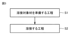
- a welding method includes a preparing step and a welding step.
- a first workpiece having a first end and a second workpiece having a second end are prepared.
- the first and second objects to be welded are arranged so that a butted portion of the first end and the second end is formed, and a non-consumable material having a central axis is The above parts are welded using an arc generated by an electrode.
- the steps of welding the parts are welded while the non-consumable electrode is moved relative to the parts.
- the central axis of the non-consumable electrode is inclined with respect to the normal to the surfaces of the first and second objects to be welded.
- the central axis is inclined with respect to the normal in a direction opposite to the direction of movement of the non-consumable electrode relative to the portion.
- the angle of inclination of the central axis with respect to the normal is 40° or more and less than 80°.
- a method for manufacturing a can body according to the present disclosure is a method for manufacturing a can body using the above welding method.
- a cylindrical body portion constituting a can body is prepared as the first object to be welded.
- the end plate of the can body is prepared as the second object to be welded.
- the first end is an annular end in the extending direction of the body.
- the second end portion is the outer peripheral portion of the end plate portion.
- the body and the end plate are arranged so that a portion where the end of the body and the outer periphery of the end plate abut against each other is formed.
- the normal line is a straight line that is perpendicular to the rotation axis and connects the rotation center axis and the tip of the non-consumable electrode.
- a welding device includes a non-consumable electrode, a power source, and a control unit.
- the non-consumable electrode has a central axis.
- a power source powers the non-consumable electrodes.
- the control unit controls the attitude of the central axis of the non-consumable electrode with respect to the workpiece.
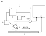
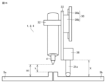
- FIG. 1 is a schematic diagram showing the configuration of a welding device according to Embodiment 1.
- FIG. 1 is a schematic diagram for explaining a welding method according to Embodiment 1.
- FIG. 3 is a flowchart of the welding method shown in FIG. 2.
- FIG. 7 is a schematic diagram for explaining a welding method according to a second embodiment.
- 5 is a schematic diagram seen from the direction indicated by the arrow in FIG. 4.
- FIG. FIG. 6 is a schematic diagram for explaining a modification of the welding method shown in FIGS. 4 and 5.
- FIG. FIG. 3 is a schematic diagram showing the configuration of a welding device according to Embodiment 3.
- FIG. 7 is a schematic diagram for explaining a welding method according to Embodiment 3.
- FIG. 7 is a flowchart of a method for manufacturing a can according to Embodiment 4.
- FIG. 10 is a schematic diagram for explaining a method of manufacturing the can body shown in FIG. 9.
- FIG. 10 is a schematic diagram for explaining a method of manufacturing the can body shown in FIG. 9.
- FIG. 10 is a schematic diagram for explaining a method of manufacturing the can body shown in FIG. 9.
- FIG. 7 is a schematic diagram showing the configuration of a welding device according to Embodiment 5.
- FIG. 7 is a schematic diagram showing the configuration of a welding device according to a sixth embodiment.
- FIG. 7 is a schematic diagram showing the configuration of a welding device according to a sixth embodiment.
- FIG. 7 is a schematic diagram showing the configuration of a welding device according to Embodiment 7.
- FIG. 3 is a graph showing the relationship between the inclination angle of the central axis of a non-consumable electrode and the maximum arc pressure. It is a graph showing the relationship between arc length and maximum arc pressure. It is a graph showing the temperature distribution at the time of arc extinguishing from the tip of the pool for each inclination angle.
- a welding device 1 is a welding device that performs the so-called TIG welding method, and includes a welding torch 2, a power source 6, a control section 7, and a drive section 8. Prepare for the Lord.
- Welding torch 2 includes a non-consumable electrode 4 and a nozzle 3.
- the non-consumable electrode 4 is, for example, a tungsten electrode.
- As the material for the non-consumable electrode 4 pure tungsten or a tungsten alloy can be used.
- the tungsten alloy for example, tungsten containing several percent of an alloying element such as lanthanum, cerium, or thorium can be used. As shown in FIG.
- the non-consumable electrode 4 has a central axis 4a.
- a non-consumable electrode 4 is arranged inside the nozzle 3. Note that, when the non-consumable electrode 4 has a rod-like shape, the central axis 4a of the non-consumable electrode 4 extends along the extending direction of the rod-shaped non-consumable electrode 4, and the central axis 4a of the non-consumable electrode 4 is an imaginary axis passing through the center of a cross section perpendicular to the extending direction of .
- the nozzle 3 supplies shielding gas around the non-consumable electrode 4.
- the nozzle 3 is connected to a shielding gas supply source (not shown).
- Shielding gas is stored in the shielding gas supply source.
- the shielding gas supplied around the non-consumable electrode 4 from the nozzle 3 is blown toward the workpiece 5 from around the non-consumable electrode 4 .
- the shielding gas any gas can be used as long as it is an inert gas used in TIG welding.
- argon gas, helium gas, or a mixed gas thereof can be used as the shielding gas.
- a mixed gas obtained by mixing about several percent of an active gas with an inert gas as described above may be used.
- the active gas constituting the mixed gas for example, oxygen gas, nitrogen gas, or hydrogen gas can be used.
- a power source 6 supplies power to the non-consumable electrode 4 of the welding torch 2.
- the negative terminal of the power source 6 is connected to the non-consumable electrode 4 of the welding torch 2.
- a positive terminal of the power source 6 is connected to the workpiece 5.
- an arc A which is a TIG arc, is generated between the non-consumable electrode 4 and the workpiece 5.
- the drive unit 8 arbitrarily changes the attitude and position of the welding torch 2 with respect to the workpiece 5.
- the control unit 7 can control the direction of the central axis 4a of the non-consumable electrode 4 with respect to the workpiece 5.
- the drive unit 8 controls the attitude of the welding torch 2 so that the central axis 4a of the non-consumable electrode 4 is inclined with respect to the normal 5c of the workpiece 5.
- any configuration can be adopted.
- a multi-axis robot arm or the like can be used as the drive unit 8.
- the relative position and posture of the non-consumable electrode 4 with respect to the workpiece 5 can be changed.
- the welding torch 2 including the non-consumable electrode 4 is fixed, it is possible to change the position and posture of the non-consumable electrode 4 relative to the workpiece 5.
- the holding member may be moved relative to the welding torch 2.
- the welding device 1 includes a moving section that moves the holding member.
- any configuration can be adopted as the moving unit, for example, an XY stage or the like may be used.
- the material of the object to be welded 5 is not particularly limited.
- Examples of the material of the object to be welded 5 include steel materials such as carbon steel, stainless steel, aluminum alloys, magnesium alloys, nickel alloys, copper alloys, titanium alloys, and the like.
- a preparation step (S1) is first performed.
- this step (S1) as shown in FIG. 2, a first workpiece 5a having a first end 5aa and a second workpiece 5b having a second end 5ba are prepared.
- a welding step (S2) is performed.
- the first workpiece 5a and the second workpiece 5b are formed such that a portion where the first end 5aa and the second end 5ba butt each other is formed. and place it.
- the above portions are welded using an arc A generated by a non-consumable electrode 4 having a central axis 4a. This will be explained in detail below.
- the first workpiece 5a and the second workpiece 5b are plate materials, and the end face of the first end 5aa and the end face of the second end 5ba are butted to form a butt joint. Become. At this time, the butted end surfaces may contact each other, but a gap (welding gap) may be formed between the two end surfaces.
- Welding is performed with the first workpiece 5a and the second workpiece 5b arranged as described above.
- shielding gas is sent to the nozzle 3 of the welding torch 2 from a shielding gas supply source (not shown).
- the power source 6 is operated to apply a welding current between the non-consumable electrode 4 and the object to be welded 5.
- arc A is generated as shown in FIG.
- the welding torch 2 is moved in a direction (welding direction) along a portion where the end surface of the first end 5aa and the end surface of the second end 5ba are butted against each other.
- the non-consumable electrode 4 moves relative to the above-mentioned part, and the said part is welded by the arc A.
- the arc A melts the surface of the object to be welded 5 (the surface of the portion where the first end 5aa and the second end 5ba are butted together), and a molten pool P is formed. Thereafter, when the welding torch 2 moves, the molten pool P is cooled and solidified to become the weld metal M. As a result, the first workpiece 5a and the second workpiece 5b are welded by the weld metal M.
- welding may be performed by fixing the welding torch 2 and moving the workpiece 5 with respect to the welding torch 2. Furthermore, in the process described above, the welding torch 2 or the workpiece 5 as the base metal is moved after the arc A is generated, but the arc A is generated while the welding torch 2 or the workpiece 5 is moved. You may let them.
- the non-consumable electrode 4 The central axis 4a is inclined.
- the normal line 5c is the normal line to the surface of the first workpiece 5a (the surface facing the welding torch 2) at the part where the first workpiece 5a and the second workpiece 5b are butted together. You may.
- the direction of inclination of the central axis 4a is opposite to the direction of movement of the welding torch 2 relative to the normal line 5c at the portion where the first workpiece 5a and the second workpiece 5b abut against each other.
- the inclination angle ⁇ of the central axis 4a with respect to the normal line 5c is 40° or more and less than 80°. Therefore, as shown in FIG.
- the arc A is formed to extend in a direction oblique to the surface of the workpiece 5. Further, the arc A has a shape that spreads further forward than the molten pool P in the direction in which welding progresses (the direction in which the welding torch 2 moves).
- the electrode protrusion length L (see FIG. 2), which is the distance from the tip of the nozzle 3 of the welding torch 2 to the tip of the non-consumable electrode 4, is not particularly limited.
- the electrode protrusion length L is preferably set to 20 mm or less. This is because there is a concern that the longer the electrode protrusion length L becomes, the worse the gas shielding properties will be, making welding unstable, or the more likely the welding part will be oxidized. However, if the configuration of the nozzle 3 is such that laminar shielding gas can be sprayed over a long distance, the electrode protrusion length L may be set to 20 mm or more.
- the welding method includes a step of preparing (S1) and a step of welding (S2).
- preparing step (S1) a first workpiece 5a having a first end 5aa and a second workpiece 5b having a second end 5ba are prepared.
- welding step (S2) the first workpiece 5a and the second workpiece 5b are arranged so that a portion where the first end 5aa and the second end 5ba are butted together is formed,
- the above parts are welded using an arc A generated by a non-consumable electrode 4 having a central axis 4a.
- the above-mentioned parts are welded while moving the non-consumable electrode 4 relative to the above-mentioned parts.
- the central axis 4a of the non-consumable electrode 4 is inclined with respect to the normal line 5c at the above-mentioned portion with respect to the surfaces of the first workpiece 5a and the second workpiece 5b.
- the central axis 4a is inclined with respect to the normal line 5c in a direction opposite to the direction of movement of the non-consumable electrode 4 with respect to the portion.
- the inclination angle ⁇ of the central axis 4a with respect to the normal line 5c is 40° or more and less than 80°.
- the arc A is formed to extend in a direction inclined with respect to the surfaces of the first workpiece 5a and the second workpiece 5b. Further, the arc A has a shape that spreads further forward than the molten pool P in the direction in which welding progresses (the direction in which the welding torch 2 including the non-consumable electrode 4 moves). Therefore, it is possible to increase the welding current supplied to the non-consumable electrode 4 and improve the welding speed while suppressing the occurrence of burn-through defects and the like. Further, by preheating the region in front of the molten pool P in the direction in which welding progresses by the arc A, the dimensional margin for the welding gap can be expanded. This will be explained in more detail below.
- a plasma airflow due to the surrounding shielding gas is generated in the direction along the central axis 4a of the non-consumable electrode 4. do.
- the plasma airflow is blown onto the workpiece 5 to be welded.
- the plasma airflow collides with the object to be welded 5, and the traveling direction of the plasma airflow changes to a direction along the surface of the object to be welded 5 (in the surface direction).
- a force acts on the workpiece 5 along the original traveling direction of the plasma airflow.
- the arc force increases as the welding current supplied to the non-consumable electrode 4 increases.
- the arc force also increases.
- the force that pushes the molten pool P downward in the thickness direction (plate thickness direction) of the workpiece 5 to be welded increases.
- defects in which the molten pool P drops downward are likely to occur. Further, such burn-through defects tend to occur more easily when the thickness (plate thickness) of the welded object 5 is thinner.
- the welding torch 2 and the non-consumable electrode 4 are tilted in a direction opposite to the direction in which welding progresses.
- the inclination angle ⁇ which is the angle between the central axis 4a of the non-consumable electrode 4 and the normal line 5c of the workpiece 5, is set in a range of 40° or more and less than 80°. Therefore, the arc force that acts to push down the molten pool P downward in the plate thickness direction can be reduced.
- the downward arc force in the plate thickness direction is halved.
- the inclination angle ⁇ is set to 0° and the value of the welding current is increased from 100 A to 200 A
- the downward arc force in the plate thickness direction increases approximately 2.2 times.
- the arc force when the welding current value is 200A is equal to or less than the arc force when the inclination angle ⁇ is 0° and the welding current value is 100A.
- the inclination angle ⁇ is 80° or more, the arc A generated between the non-consumable electrode 4 and the workpiece 5 to be welded becomes unstable, and welding quality may deteriorate or welding may not be possible. From the above, by setting the inclination angle ⁇ to 40° or more and less than 80°, it is possible to suppress the arc force that acts in a downward direction (downward) on the molten pool P during welding. Therefore, the welding current can be increased without causing burn-through defects, and as a result, the welding speed can be increased.
- the inclination angle ⁇ is set to 45° or more and 75° or less.
- the welding method according to the first embodiment when welding thin plate materials having a thickness of 0.1 mm or more and 2 mm or less as the first workpiece 5a and the second workpiece 5b, It is possible to increase the dimensional margin for the gap (welding gap) created when the first workpiece 5a and the second workpiece 5b are butted together.
- the welding gap when welding thin plate materials, if the welding gap is large, there will be a shortage of material to fill the welding gap. Therefore, even if the molten metals of the first welded object 5a and the second welded object 5b are not joined together, or even if the molten metals are joined together to form a molten pool P, burn-through defects due to arc force may occur. There are concerns that such problems may occur. Therefore, for example, in a butt joint by TIG welding that does not use a welding wire, the maximum allowable welding gap is about 20% of the plate thickness of the workpiece 5 to be welded. Therefore, when the thickness of the workpiece 5 is 2 mm or less, the welding gap is assumed to be 0.4 mm or less.
- the welding torch 2 is tilted in the opposite direction to the direction in which welding progresses, and the tilt angle ⁇ is set in the range of 40° or more and less than 80°, as shown in FIG. has been done. Therefore, the generated arc A has a shape that spreads farther forward than the molten pool P in the direction in which welding progresses. Therefore, the effect of preheating the front region of the molten pool P can be obtained.
- the front region is preheated, the temperature of the weld object 5 in the front region increases, and the weld object 5 (the first weld object 5a and the second weld object 5b) thermally expands in a direction that reduces the welding gap. .
- the weld object 5 the first weld object 5a and the second weld object 5b
- the welding device 1 includes a non-consumable electrode 4, a power source 6, and a control unit 7.
- Non-consumable electrode 4 has a central axis 4a.
- a power source 6 supplies power to the non-consumable electrode 4.
- the control unit 7 controls the attitude of the central axis 4a of the non-consumable electrode 4 with respect to the workpiece 5. In this case, the welding method described above can be easily carried out using the welding device 1.
- the thickness of the workpiece 5 to be welded is 2 mm or less.
- the depth of the molten pool P becomes shallow, and it is difficult to completely melt the workpiece 5 in the entire thickness direction of the workpiece 5. may be difficult.
- the welding method according to the second embodiment basically has the same configuration as the welding method shown in FIGS. 2 and 3, and can obtain similar effects.
- the shape of the workpiece 5 is different from the welding method shown in FIGS. 2 and 3. That is, in the welding method shown in FIGS. 4 and 5, the ends of the first workpiece 5a and the second workpiece 5b are bent as shown in FIG. Note that FIG. 5 shows the end portions of the first workpiece 5a and the second workpiece 5b viewed from the direction shown by the arrow 10 in FIG.
- the first end portion 5aa of the first workpiece 5a includes a bent portion 5aa1 and an extending portion 5aa2.
- the bent portion 5aa1 is bent to have an L-shape in a cross section perpendicular to the moving direction of the welding torch 2.
- the extending portion 5aa2 extends from the bent portion 5aa1 in a direction along the normal line 5c (see FIG. 4).
- the second end portion 5ba of the second workpiece 5b includes a bent portion 5ba1 and an extended portion 5ba2.
- the bent portion 5ba1 is bent to have an L-shape in the cross section.
- the extending portion 5ba2 extends from the bent portion 5ba1 in a direction along the normal line 5c (see FIG. 4).
- the bent portion 5ba1 of the second end portion 5ba is arranged so as to face the bent portion 5aa1 of the first end portion 5aa.
- the extending portion 5ba2 of the second end portion 5ba is arranged so as to face the extending portion 5aa2 of the first end portion 5aa. In this way, the portion where the first workpiece 5a and the second workpiece 5b are butted has a bow joint shape.
- the welding method described above can be performed using the welding apparatus 1 according to the first embodiment.
- the arc A is formed so as to go toward the extending portion 5aa2 of the first end 5aa and the extending portion 5ba2 of the second end 5ba. .
- the extending portions 5aa2 and 5ba2 are melted by the arc A and flow downward, thereby becoming part of the molten pool P.
- the extension parts 5aa2 and 5ba2 are sequentially melted and a molten pool P is formed.
- first end 5aa and the second end 5ba may be bent.
- first end portion 5aa includes a bent portion 5aa1 and an extension portion 5aa2.
- the second end portion 5ba is not bent.
- the end surface of the second end portion 5ba is arranged to face the bent portion 5aa1 of the bent first end portion 5aa.
- one of the first end 5aa and the second end 5ba (the first end 5aa in FIG. 6) is It may also include a bent portion 5aa1 and an extended portion 5aa2.
- the bent portion 5aa1 may be bent to have an L-shape in a cross section perpendicular to the movement direction.
- the extending portion 5aa2 may extend from the bent portion 5aa1 in a direction along the normal line 5c.
- the other of the first end 5aa and the second end 5ba (the second end 5ba in FIG. 6) may be arranged to face the bent portion 5aa1.
- the other of the first end 5aa and the second end 5ba may include a bent portion 5ba1 and an extended portion 5ba2.
- the bent portion 5ba1 may be bent to have an L-shape in the cross section.
- the extending portion 5ba2 may extend from the bent portion 5ba1 in a direction along the normal line 5c.
- the bent portion 5ba1 of the second end portion 5ba may be arranged so as to face the bent portion 5aa1 of the first end portion 5aa.
- the extending portion 5ba2 of the second end portion 5ba may be arranged so as to face the extending portion 5aa2 of the first end portion 5aa.
- the arc A preheats the front region of the molten pool P.
- the first end 5aa or the second end 5ba having an L-shaped cross section is thermally deformed.
- the first end 5aa or the second end 5ba is thermally deformed in a direction in which residual stress is released when the first end 5aa or the second end 5ba is processed into an L-shape.
- the thermal deformation causes the first end 5aa or the second end 5ba to deform so that the degree of L-shaped bending becomes gentle.
- the weld gap becomes smaller due to the deformation of the L-shape in a direction where the degree of bending becomes gentler. Therefore, the inclination angle ⁇ , which is the angle between the central axis 4a of the non-consumable electrode 4 of the welding torch 2 and the direction of the normal line 5c of the workpiece 5, is set in the range of 40° or more and less than 80°, and the L-shaped
- the dimensional margin for the welding gap can be further increased than in the welding method according to the first embodiment.
- the angle between the surface of the molten part in the extension parts 5aa2, 5ba2 at the first end 5aa or second end 5ba of the L-shape during welding and the normal 5c shown in FIG. 4 is about 0°. (The surface of the molten part extends almost vertically) is considered. On the other hand, it is also possible that the angle is about 80°.
- the angle changes depending on welding conditions such as the inclination angle ⁇ , which is the angle between the central axis 4a of the non-consumable electrode 4 and the normal line 5c of the workpiece 5, welding current, welding speed, etc. Note that it is preferable to avoid a situation where the angle is approximately 0°.
- the dimensional margin for the welding gap can be further increased. can be made larger. Further, compared to a method of increasing the dimensional margin of the welding gap using a welding rod or welding wire for a butt joint, the welding speed can be made higher.
- the welding device 1 according to the third embodiment basically has the same configuration as the welding device 1 shown in FIG.
- the welding apparatus 1 differs from the welding apparatus 1 shown in FIG. 1 in that it further includes a section 9.
- the welding apparatus 1 shown in FIG. 7 includes a detection section 9 connected to a control section 7.
- the detection unit 9 detects displacement of the workpiece 5 to be welded.
- a sensor 9a that directly measures the displacement of the object to be welded 5 can be used.
- a position sensor such as a laser displacement meter, an imaging device that acquires image data to measure the displacement of the object to be welded 5 based on image data, or the like can be used.
- the position of the top surface of the extending portions 5aa2, 5ba2 of the first end 5aa or the second end 5ba shown in FIG. 8, for example, may be detected by the sensor 9a. In this case, it is preferable that the sensor 9a be placed at a position where it is not affected by the arc A. As shown in FIG.
- the arc A has a shape that spreads toward the front in the welding progress direction (direction from the non-consumable electrode 4 toward the extension parts 5aa2 and 5ba2 in FIG. 8). Therefore, when measuring the displacement of the workpiece 5 near the welding part, it is necessary to consider the influence of the arc A.
- a filter that blocks light from the arc A may be installed on the sensor 9a.
- a voltage sensor 9b that measures an arc voltage indicating the state of the arc A can be used.
- the distance between the object to be welded 5 and the non-consumable electrode 4 changes, resulting in a change in the arc voltage. Therefore, the displacement of the object to be welded 5 can be measured indirectly by the arc voltage.
- the control unit 7 controls the drive unit 8 according to the displacement of the workpiece 5 detected by the detection unit 9.
- the drive unit 8 can change the position of the welding torch 2 with respect to the workpiece 5. Therefore, the position of the welding torch 2, that is, the position of the non-consumable electrode 4 can be adjusted.
- the welding method using the welding device 1 shown in FIG. 7 basically has the same configuration as the welding method shown in FIG. ), the method of controlling the position of the non-consumable electrode 4 of the welding torch 2 is different from the welding method shown in FIG. That is, in the welding method shown in FIG. 8, during welding, the distance H1 from the bent portions 5aa1, 5ba1 to the non-consumable electrode 4 in the direction of the normal line 5c is from the bent portions 5aa1, 5ba1 to the extending portions 5aa2, 5ba2.
- the position of the welding torch 2 is controlled so that the distance to the top surface of the welding torch 2 is at least H2.
- the position of the welding torch 2 is adjusted so that the distance h from the top surface of the extension parts 5aa2, 5ba2 to the non-consumable electrode 4 in the direction along the normal line 5c is greater than or equal to zero, preferably greater than zero. be done.
- the position of the welding torch 2 is controlled by a drive unit 8 based on a signal from a control unit 7.
- the detection unit 9 detects the displacement of the extension portions 5aa2 and 5ba2.
- a signal indicating the displacement of the extension portions 5aa2 and 5ba2 is transmitted from the detection unit 9 to the control unit 7.
- the control unit 7 adjusts the distance H1 from the bending parts 5aa1 and 5ba1 to the non-consumable electrode 4 so as to maintain the state of the arc A appropriately.
- the non-consumable electrode 4 is arranged so as to be inclined with respect to the normal line 5c, the arc A is directed diagonally upward with respect to the extending portions 5aa2 and 5ba2 of the workpiece 5. sprayed from. The portions of the extension portions 5aa2 and 5ba2 melted by the arc A become part of the molten pool P.
- the distance H1 from the bent portions 5aa1, 5ba1 to the non-consumable electrode 4 is greater than or equal to the distance H2 from the bent portions 5aa1, 5ba1 to the top surfaces of the extension portions 5aa2, 5ba2 in the direction of the normal line 5c. You can leave it there.
- the non-consumable electrode 4 is arranged at a position sufficiently away from the workpiece 5 to be welded, the arc force that acts to push the molten pool P downward in the thickness direction can be reduced.
- the distance H1 from the bent portions 5aa1, 5ba1 to the non-consumable electrode 4 may be adjusted according to the displacement of the extension portions 5aa2, 5ba2.
- the welding step (S2) even if the extending parts 5aa2, 5ba2 of the welded object 5 are displaced due to thermal deformation, the non-consumable electrode 4 and the extending parts 5aa2, 5ba2 of the welded object 5 The distance between the two can be maintained within an appropriate range. As a result, the welding quality in the welding step (S2) can be stabilized.
- the welding apparatus 1 may include a detection section 9 that detects the displacement of the object to be welded 5.
- the control unit 7 may control the position of the non-consumable electrode 4 according to the displacement of the workpiece 5 detected by the detection unit 9. As a result, by using the welding apparatus 1, the welding quality can be stabilized even if the workpiece 5 is thermally deformed during welding.
- Embodiment 4 A method for manufacturing a can body according to this embodiment will be described below.
- a step (S10) of preparing can parts is first performed.
- This step (S10) corresponds to the preparing step (S1) shown in FIG.
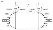
- the body portion 21 and end plate portion 22 that constitute the can body 20 are prepared.
- the can body 20 is, for example, a metal hot water storage tank in a hot water storage type water heater.
- the body portion 21 has a cylindrical shape.
- the body portion 21 corresponds to the first object to be welded 5a.
- the end plate portion 22 has a U-shaped or semicircular cup shape in cross section.
- the mirror plate portion 22 corresponds to the second object to be welded 5b.
- An annular end portion 21a in the extending direction of the body portion 21 corresponds to the first end portion 5aa in FIGS. 4 and 5.
- the outer peripheral portion 22a of the end plate portion 22 corresponds to the second end portion 5ba in FIGS. 4 and 5.
- the end portion 21a of the body portion 21 and the outer peripheral portion 22a of the mirror plate portion 22 are formed with bent portions and extended portions as shown in FIGS. 4 and 5.
- a welding step (S20) is performed.
- This step (S20) corresponds to the welding step (S2) shown in FIG. 3.
- the body part 21 and the end plate part 22 are assembled so that a portion where the end part 21a of the body part 21 and the outer circumferential part 22a of the end plate part 22 butt each other is formed. Placed. The portion where the end portion 21a and the outer circumferential portion 22a butt each other is a joint.
- the bending part and the extending part may not be formed in the end part 21a and the outer peripheral part 22a, and the said part may serve as a simple butt joint.
- the body part 21 and the mirror plate part 22 are arranged so that the rotation center axis 21b (see FIG. 11) of the body part 21 extends along the horizontal direction.
- the two mirror plate parts 22 are arranged so as to sandwich the body part 21 therebetween.
- a jig 25 is installed on the end plate portion 22. Stress is applied to the end plate portion 22 by the jig 25 in the direction shown by the arrow in FIG. In this state, the welding torch 2 is placed so as to face the portion where the end portion 21a of the body portion 21 and the outer peripheral portion 22a of the mirror plate portion 22 are butted against each other.
- a welding torch 2 containing a non-consumable electrode 4 is fixed.
- the body part 21 and the mirror plate part 22 in the direction shown by the arrow in FIG. 21a and the outer circumferential portion 22a (the portion to be welded) are welded.
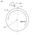
- a straight line 20a that is perpendicular to the rotation center axis 21b and connects the rotation center axis 21b and the tip of the non-consumable electrode 4.
- the straight line 20a corresponds to the normal line 5c shown in FIG. 4.
- the central axis 4a of the non-consumable electrode 4 is inclined with respect to the straight line 20a in the direction opposite to the moving direction of the non-consumable electrode 4 (the direction indicated by the arrow in FIG. 11).
- the inclination angle ⁇ of the central axis 4a with respect to the straight line 20a corresponding to the normal line 5c is 40° or more and less than 80°.
- the position of the welding torch 2 may be determined as shown in FIG. 12. That is, consider a line segment 20b that connects the rotation center axis 21b and the apex 21c located at the uppermost position of the body portion 21 when viewed from the direction along the rotation center axis 21b of the body portion 21.
- the non-consumable electrode 4 of the welding torch 2 is located at a position on the outer periphery side of the body part 21 and the end plate part 22 and overlaps the line segment 20b, or at a position further than the line segment 20b in the rotational direction of the body part 21 and the end plate part 22. It is located in the area located on the front side.
- the non-consumable electrode 4 extends from the topmost vertex 21c of the body part 21 to the front side in the rotational direction of the body part 21 and the mirror plate part 22 (the direction indicated by the arrow in FIG. 12). placed in the area.
- step (S20) the welding method shown in Embodiment 2 is applied as described above, but even if the welding method shown in Embodiment 1 or 3 is applied. good.
- a method for manufacturing the can body 20 according to the present disclosure is a method for manufacturing the can body 20 using the above welding method.
- the cylindrical body portion 21 constituting the can body 20 is prepared as the first object to be welded 5a.
- the end plate portion 22 of the can body 20 is prepared as the second object to be welded 5b.
- the first end portion 5aa is an annular end portion 21a in the extending direction of the body portion 21.
- the second end portion 5ba is the outer peripheral portion 22a of the mirror plate portion 22.
- the body part 21 and the end plate part 22 are arranged so that a portion where the end part 21a of the body part 21 and the outer peripheral part 22a of the end plate part 22 butt each other is formed.
- the body part 21 and the end plate part 22 are welded while being rotated about a rotation center axis 21b extending along the direction in which the body part 21 extends.
- the normal line 5c is a straight line 20a that is perpendicular to the rotation center axis 21b and connects the rotation center axis 21b and the tip of the non-consumable electrode 4.
- connection portion between the body portion 21 and the end plate portion 22 can be a high-quality welded portion.
- the body portion 21 and the end plate portion 22 may be arranged so that the rotation center axis 21b extends along the horizontal direction.
- the non-consumable electrode 4 is arranged in a region on the front side in the rotation direction of the body part 21 and the end plate part 22 from the topmost apex 21c of the body part 21. You can leave it there.
- the welding device 1 according to the fifth embodiment basically has the same configuration as the welding device 1 shown in FIG.
- the configuration of the section 8 differs from the welding apparatus 1 shown in FIG. 1 in that it includes a linear guide 30 and a guide section 31.
- FIG. 16 a structure near the welding torch 2 in the welding apparatus 1 is shown.
- the guide portion 31 is arranged so as to be in contact with the workpiece 5 to be welded.
- Welding torch 2 is connected to linear guide 30.
- the linear guide 30 is connected to a guide section 31.
- the linear guide 30 adjusts the position of the welding torch 2 by moving during welding.
- the guide section 31 detects the displacement of the workpiece 5 to be welded, and the linear guide 30 moves in accordance with the displacement. As the linear guide 30 moves, the welding torch 2 connected to the linear guide 30 also moves. This will be explained in detail below.
- the linear guide 30 includes a linear guide rail 30a and a linear guide block 30b.
- a torch holder 32 is connected to the linear guide block 30b via, for example, a flat plate 33.
- Welding torch 2 is connected to torch holder 32 .
- the linear guide rail 30a is connected to the drive section 8 (see FIG. 1).
- the guide section 31 includes a guide roller 31a and a bracket 31b.
- As the bracket 31b a member having an L-shaped cross section as shown in FIG. 13 may be used, but a member having any other arbitrary shape may also be used.
- the guide portion 31 is connected to a flat plate 33 connected to the linear guide block 30b. In other words, the guide portion 31 and the welding torch 2 are connected to the linear guide block 30b by the same flat plate 33.
- the bracket 31b is included in the configuration of the guide portion 31, but the guide roller 31a may be directly connected to the flat plate 33 depending on the case. In this case, the guide portion 31 consists of only the guide roller 31a.
- the guide roller 31a for example, a ball roller having a rotatable ball at its tip can be used.
- the guide roller 31a is arranged so as to be in contact with the workpiece 5 to be welded. Therefore, other members than the ball roller can be used as long as they can be slid against the workpiece during welding.
- the welding method using the welding device 1 shown in FIG. 13 basically has the same configuration as the welding method shown in FIG. 4 or FIG.
- step (S2) the method of controlling the position of the non-consumable electrode 4 of the welding torch 2 is different from the welding method shown in FIG. 4 or FIG. 8. That is, in the welding method using the welding apparatus shown in FIG. 13, the guide portion 31 is arranged so as to be in contact with the workpiece 5 during welding. Therefore, the position of the non-consumable electrode 4 of the welding torch 2 is controlled by displacing the linear guide 30 in accordance with the displacement of the workpiece 5 . Specifically, in the normal line 5c direction (see FIG. 8), the distance H1 from the bent part of the workpiece 5 to the non-consumable electrode 4 (or from the top surface of the extending part of the workpiece 5 to the non-consumable electrode The distance h) to the electrode 4 is adjusted.
- the guide portion 31 and the welding torch 2 are integrally constructed and connected to the linear guide 30. From a different perspective, the guide section 31 and the welding torch 2 are connected to the linear guide 30 in a state where the relative positional relationship between the guide section 31 and the welding torch 2 is fixed. The position of the non-consumable electrode 4 of the welding torch 2 is controlled by the guide part 31 and the linear guide 30. In the method of controlling the position of the non-consumable electrode 4 of the welding torch 2 using the detection unit 9 shown in FIG. There is a concern that a considerable time lag may occur in controlling the position of the electrode 4.
- the guide section 31 comes into contact with the workpiece 5 and the displacement of the workpiece 5 can be directly detected by the guide section 31. Since the guide portion 31 and the welding torch 2 are integrated and can be moved by the linear guide 30, the position of the non-consumable electrode 4 can be directly adjusted in accordance with the displacement of the workpiece 5.
- the non-consumable electrode 4 and the guide portion 31 are mechanically connected, the influence of the welding speed can be suppressed in adjusting the position of the non-consumable electrode 4. As a result, the welding quality in the welding step (S2) can be made more stable.
- the welding device 1 includes a guide section 31 and a linear guide 30 as an adjustment section.
- the guide portion 31 contacts the workpiece 5 to be welded.
- a linear guide 30 serving as an adjustment section is connected to a guide section 31 and a non-consumable electrode 4.
- the linear guide 30 as an adjustment section adjusts the position of the non-consumable electrode 4 according to the displacement of the workpiece 5 detected via the guide section 31. In this case, welding quality can be stabilized.
- the welding device 1 according to the sixth embodiment basically has the same configuration as the welding device 1 shown in FIG. 13, and can obtain similar effects, but the drive unit 8 is different from the welding apparatus 1 shown in FIG. 13 in that it further includes a moving stage 34.
- the moving stage 34 is connected between the linear guide 30 and the welding torch 2.
- the moving stage 34 is arranged to connect the plate 33 connected to the linear guide 30 and the plate 35.
- the moving stage 34 can change the relative position of the plate 35 with respect to the plate 33.
- a torch holder 32 is fixed to the plate 35.
- the welding torch 2 is connected to the torch holder 32.
- the distance between the tip of the guide roller 31a and the tip of the non-consumable electrode 4 of the welding torch 2 is adjusted by the moving stage 34. That is, the distance h between the object to be welded 5 and the non-consumable electrode 4 (or the distance H1 from the bent portions 5aa1, 5ba1 of the object to be welded 5 to the non-consumable electrode 4) can be adjusted by the moving stage 34. From a different perspective, the movable stage 34 can change the relative position between the contact position between the guide portion 31 and the workpiece 5 and the non-consumable electrode 4. In FIG.
- the moving stage 34 is provided between the linear guide 30 and the welding torch 2, but if the distance h between the workpiece 5 and the non-consumable electrode 4 can be adjusted, the moving stage 34 can be placed between the linear guide 30 and the welding torch 2. It may be placed at any position.
- the moving stage 34 may be arranged to connect the linear guide 30 and the guide section 31, and the relative position of the guide section 31 with respect to the linear guide 30 may be adjusted by the moving stage 34.
- FIG. 15 is a schematic diagram showing the configuration of a modification of the welding device 1 according to the sixth embodiment.
- a modification of the welding device 1 according to the sixth embodiment basically has the same configuration as the welding device 1 shown in FIG. 13, and can obtain similar effects.
- the welding apparatus 1 differs from the welding apparatus 1 shown in FIG. 13 in that the drive unit 8 further includes an air cylinder 36.
- the air cylinder 36 is arranged to connect the linear guide 30 and the guide section 31. Specifically, the air cylinder 36 connects the plate 33 connected to the linear guide 30 and the guide roller 31a of the guide section 31. The air cylinder 36 adjusts the protruding length X of the guide roller 31a from the lower end of the plate 33. That is, the distance h between the workpiece 5 and the non-consumable electrode 4 can be adjusted by the air cylinder 36. From a different perspective, the relative position between the contact position between the guide portion 31 and the workpiece 5 and the non-consumable electrode 4 can be changed by the air cylinder 36. In FIG.
- the air cylinder 36 is provided between the linear guide 30 and the guide part 31, but if the distance h between the workpiece 5 and the non-consumable electrode 4 can be adjusted, the air cylinder 36 can be moved to another position. It may be placed in For example, an air cylinder 36 may be provided between the linear guide 30 and the welding torch 2, and the relative position of the welding torch 2 with respect to the linear guide 30 may be adjusted by the air cylinder 36.
- the moving stage 34 and the air cylinder 36 are connected to the control section 7 (see FIG. 1).
- the control unit 7 controls the moving stage 34 and the air cylinder 36. Therefore, the position of the welding torch 2 relative to the workpiece 5 can be changed by the moving stage 34 and the air cylinder 36 controlled by the control unit 7. As a result, the position of the welding torch 2, ie, the position of the non-consumable electrode 4, can be adjusted.
- the welding method using the welding device 1 shown in FIGS. 14 and 15 basically has the same configuration as the welding method using the welding device 1 shown in FIG. 13, and can obtain the same effects. However, it differs from the welding method shown in FIG. 13 in that in the welding step (S2), the distance h between the workpiece 5 and the non-consumable electrode 4 can be changed during welding. .
- the distance h between the workpiece 5 and the non-consumable electrode 4 adjusted in the step (S1) of preparing the material to be welded is adjusted in the welding step (S1). In S2), it is maintained constant according to the displacement of the workpiece 5 to be welded.
- the control unit 7 controls the moving stage 34 or the air cylinder 36 even in the welding step (S2), so that the workpiece 5 and the non-consumable electrode 4 are connected to each other. Distance h can be adjusted during welding.
- the controller 7 By controlling the cylinder 36, it is possible to adjust the distance h between the workpiece 5 and the non-consumable electrode 4 for each welding location. As a result, the welding quality in the welding step (S2) can be made more stable.
- the appropriate value of the distance h between the workpiece 5 and the non-consumable electrode 4 changes at each of the welding start position, steady state part, and end position.
- the steady portion is a position between the welding start position and the welding end position.
- the shape of the weld at the start position that is, the width and height of the weld, changes depending on the distance h.
- the bent parts 5aa1, 5ba1 and the extension parts 5aa2, 5ba2 shown in FIGS. 4 and 5 have already been welded at the welding start position, so the shape of the welded part has changed.
- the welding part is lapped until the welding start and end positions are the same or the end position exceeds the start position. Therefore, it is undesirable for the shape of the welded part at the welding start position to be extremely different from the shape of the welded part at the welded end position because the shape of the welded part will be non-uniform. Therefore, it is preferable to appropriately adjust the distance h between the workpiece 5 and the non-consumable electrode 4 at each position. Furthermore, the appropriate value for the distance h between the workpiece 5 and the non-consumable electrode 4 may not be uniquely determined because it may change depending on the performance required of the welding part. In such a case, the welding method using the welding apparatus 1 shown in FIGS. 14 and 15 is effective.
- the following method can be used to change the distance h between the welding start position, steady portion, and end position.
- the distance is calculated at each of the angle corresponding to the start position, the angle corresponding to the steady part, and the angle corresponding to the end position of the weld.
- the distance h may be adjusted by controlling the moving stage 34 or the air cylinder 36 by the control unit 7 when the welding portion reaches a predetermined angle.
- Another method is to calculate in advance the time required to perform all-around welding, and calculate the time corresponding to the welding start position, the time corresponding to the steady part, and the time corresponding to the end position. Set the distance h with .
- the distance h may be adjusted by controlling the moving stage 34 or the air cylinder 36 by the controller 7.
- the angle and time have been explained as an example as criteria for adjusting the distance h, but the invention is not limited to this, and for example, the distance h may be set based on the length to be welded.
- the distance h is not limited to this, and the parts where the distance h is set can be increased or decreased depending on the workpiece 5. You can.
- the welding apparatus 1 may include the moving stage 34 between the linear guide 30 and the welding torch 2 as described above. Furthermore, an air cylinder 36 may be provided between the linear guide 30 and the guide portion 31.
- the control unit 7 may control the distance h between the workpiece 5 and the non-consumable electrode 4 by controlling the moving stage 34 and the air cylinder 36.
- the projecting length X of the guide roller 31a of the guide portion 31 may be configured to be adjustable with a screw. Furthermore, it may include a driver for the screw that can automatically adjust the length X.
- the control unit 7 may adjust the protruding length X of the guide roller 31a by controlling the drive unit.
- the welding device 1 may include a plurality of guide rollers 31a, and the protruding length The length X may be adjusted. As a result, by using the welding apparatus 1 described above, welding quality can be stabilized even if the appropriate distance h changes for each welding location of the workpiece 5.
- the distance H1 from the bent portions 5aa1 and 5ba1 to the non-consumable electrode 4 (that is, the distance h between the workpiece 5 and the non-consumable electrode 4) is , can be changed for each different position of the portion where the first end of the first workpiece 5a and the second end of the second workpiece 5b abut against each other. In this case, welding quality can be stabilized.
- the welding device includes a moving stage 34 or an air cylinder 36 as a position adjustment mechanism.
- the position adjustment mechanism (moving stage 34 or air cylinder 36) can change the relative position between the contact position between the guide portion 31 and the workpiece 5 and the non-consumable electrode 4.
- the control unit 7 changes the relative position between the contact position and the non-consumable electrode 4 by controlling a position adjustment mechanism (moving stage 34 or air cylinder 36). In this case, even if the optimal distance H1 (or distance h) differs for each part to be welded, welding quality can be stabilized.
- Embodiment 7 ⁇ Welding method>
- the welding method according to the seventh embodiment basically has the same configuration as the welding method shown in FIGS. 2 and 3, and can obtain the same effects, but in the welding step (S2).
- the operation of the control unit 7 is different. That is, in the welding method according to the seventh embodiment, in the welding step (S2), the control unit 7 (see FIG. 1) controls the workpiece 5 (see FIG. 2) while the arc A (see FIG. 2) is generated.
- the drive unit 8 (see FIG. 1) is controlled according to the welding location of the workpiece (see FIG. 1), and the attitude of the central axis 4a (see FIG. 16) of the non-consumable electrode 4 (see FIG. 16) with respect to the workpiece 5 is controlled. do.
- control unit 7 controls the drive unit 8 so that the inclination angle ⁇ of the central axis 4a with respect to the normal line 5c is set to 40° or more and 80° while the arc A is generated, as shown in FIG. Adjust within the range below.
- the attitude of the central axis 4a of the non-consumable electrode 4 with respect to the workpiece 5 may be controlled so that the tip position of the non-consumable electrode 4 changes, but preferably the tip position of the non-consumable electrode 4 may be controlled. It is preferable to control the attitude of the central axis 4a of the non-consumable electrode 4 so as not to change.
- the torch holder 32 holding the welding torch 2 may be moved along an arcuate trajectory. Specifically, the torch holder 32 is fitted into a groove of a plate provided with a groove into which the torch holder 32 is fitted. The torch holder 32 is moved along the groove. Any method can be used to move the torch holder 32. For example, a telescoping cylinder may be connected to the torch holder 32, and the torch holder 32 may be moved along the groove by expanding and contracting the telescoping cylinder.
- the control section 7 controls the drive section 8 to align the center axis 4a of the non-consumable electrode 4 with respect to the workpiece 5.
- Control your posture In this case, for example, when it is necessary to change the attitude of the central axis 4a of the non-consumable electrode 4 with respect to the workpiece 5, that is, the inclination angle ⁇ of the central axis 4a with respect to the normal line 5c, depending on the welding location, It becomes possible to set an appropriate inclination angle ⁇ for each welding location. As a result, the welding quality in the welding step (S2) can be made more stable.
- the inclination angle ⁇ is set between the first end of the first workpiece 5a and the second workpiece 5b in a range of 40° or more and less than 80°. It can be changed for each different position of the part where the second end of In this case, welding quality can be stabilized.
- Example 1 The material constituting the sample is SUS436L specified in the JIS standard.
- the shape of the sample is a plate.
- the plate thickness which is the thickness of the sample, was 0.6 mm.
- the end portion that would become the welded portion was bent into an L shape. The bent portions were butted together to form a welded portion.
- ⁇ Test method> The above welded portion was welded using a TIG welding device having the configuration shown in FIG.
- a shim plate was placed between the opposing objects to be welded at the welding section.
- the inclination angle ⁇ which is the angle between the normal line at the welding part of the workpiece and the central axis 4a of the tungsten electrode (see FIG. 2), which is the non-consumable electrode 4 of the welding torch 2
- Welding was performed at different angles of angles of 50°, 50°, and 60°. Thereafter, the condition of the welded area was visually checked.
- Table 1 The welding conditions are shown in Table 1.
- the value of the weld gap at which good welding quality can be obtained may be doubled or tripled. Shown.
- FIG. 17 shows the relationship between the inclination angle and the vertically downward pressure component of the arc pressure.
- the horizontal axis indicates the inclination angle
- the vertical axis indicates the vertically downward pressure component of the arc pressure.
- the maximum value during measurement also referred to as maximum arc pressure
- FIG. 17 shows relative values when the pressure component is 1 when the inclination angle is 0°, the welding current is 100 A, and the arc length is 3 mm.
- the welding current was 100 A or 200 A, and the inclination angle was 0°, 25°, and 50°.
- the degree of decrease in maximum arc pressure when the inclination angle is set to 25° is greater than that when the inclination angle is set to 25° compared to the case where the inclination angle is set to 25°.
- the degree of decrease in maximum arc pressure is relatively large when the angle is set to 50°.
- the maximum arc pressure is halved compared to when the inclination angle is 0°. Furthermore, when the inclination angle is 0°, by increasing the welding current from 100 A to 200 A, the maximum arc pressure is approximately 2.2 times greater. On the other hand, the maximum arc pressure when the welding current is 200 A and the inclination angle is 50° is equal to or lower than the maximum arc pressure when the welding current is 100 A and the inclination angle is 0°. Such a tendency can be confirmed when the inclination angle is 40° or more. In this way, it was shown that the increase in arc pressure due to increase in welding current can be suppressed by increasing the inclination angle.
- FIG. 18 shows the relationship between the arc length and the vertically downward pressure component of the arc pressure.
- the horizontal axis represents the arc length
- the vertical axis represents the vertically downward pressure component of the arc pressure.
- the pressure component the maximum value during measurement (also referred to as maximum arc pressure) was adopted as in FIG. 17.
- FIG. 18 shows relative values when the above pressure component is set to 1 when the inclination angle is 0°, the welding current is 100 A, and the arc length is 1 mm. Measurements were conducted under the following conditions: the welding current was 100 A or 200 A, and the arc length was 1 mm, 3 mm, and 5 mm. The inclination angle under each condition was 0°.
- the maximum arc pressure also changes as the arc length changes.
- the arc pressure can be reduced by increasing the arc length, that is, by increasing the height from the workpiece to the tip of the tungsten electrode.
- ⁇ Test method> The temperature distribution at the end of welding in the front region of the molten pool was measured by changing the inclination angle (torch angle) of the central axis of the tungsten electrode as a non-consumable electrode.
- a K-type thermocouple was used as the temperature measuring device. Table 4 shows the conditions during measurement.
- results are shown in FIG.
- the horizontal axis indicates the distance from the tip of the melt pool.
- the vertical axis indicates the temperature at each position of the welded object at the end of welding (that is, when the arc is extinguished).
- results are shown for tilt angles of 25° and 60°.
- the temperature in the front region of the melt pool was higher when the inclination angle was 60° than when the inclination angle was 25°. In other words, it was shown that by increasing the inclination angle, the preheating effect in the front region of the melt pool could be increased.
Abstract
Provided are a welding method and a welding device which use a consumable electrode and can achieve both an increase in welding speed and an enlargement of the dimensional margin for a weld gap. This welding method comprises a preparation step and a welding step. This welding method comprises a preparation step and a welding step. In the welding step, in a state in which a first object (5a) to be welded and a second object (5b) to be welded are disposed such that a portion where a first end (5aa) and a second end (5ba) abut each other is formed, an arc (A) generated by a non-consumable electrode (4) having a center axis (4a) is used to weld said portion. The center axis (4a) of the non-consumable electrode (4) is inclined relative to a normal line (5c) to said portion relating to the surfaces of the first object (5a) to be welded and the second object (5b) to be welded. The center axis (4a) is inclined relative to the normal line (5c) toward the opposite direction of a movement direction of the non-consumable electrode (4) relative to said portion. The inclination angle θ of the center axis (4a) relative to the normal line (5c) is at least 40° but less than 80°.
Description
本開示は、溶接方法、缶体の製造方法および溶接装置に関する。
The present disclosure relates to a welding method, a can manufacturing method, and a welding device.
従来、非消耗性電極を用いた溶接方法が知られている。たとえば、不活性ガス雰囲気中で非消耗性電極であるタングステン電極と被溶接物との間にアークを発生させるTIG(Tungsten Inert Gas)溶接法は、スパッタの発生が少なく高品質な溶接部が得られることから、缶体を構成する部材または薄板部材などの溶接において広く採用されている。しかし、TIG溶接法のような非消耗性電極を用いた溶接方法では、消耗性電極を用いたMAG(Metal Active Gas)溶接法およびMIG(Metal Inert Gas)溶接法と比較して溶接速度が遅く、被溶接物の間の隙間(溶接ギャップ)についての寸法余裕が小さいという課題があった。
Conventionally, welding methods using non-consumable electrodes are known. For example, the TIG (Tungsten Inert Gas) welding method, which generates an arc between a non-consumable tungsten electrode and the workpiece in an inert gas atmosphere, produces high-quality welds with less spatter. Because of this, it is widely used for welding members constituting can bodies or thin plate members. However, welding methods using non-consumable electrodes such as TIG welding have a slower welding speed than MAG (Metal Active Gas) welding and MIG (Metal Inert Gas) welding using consumable electrodes. However, there was a problem in that the dimensional margin for the gap between the objects to be welded (welding gap) was small.
このため、たとえば特開2012-139704号公報では、タングステン電極が設置された溶接トーチのノズルから2重のシールドガスを流すことで、アークのエネルギー密度、アークの指向性などを高めて溶接速度の高速化を図っている。
For this reason, for example, in Japanese Patent Application Laid-Open No. 2012-139704, double shielding gas is flowed from the nozzle of a welding torch equipped with a tungsten electrode to increase the arc energy density, arc directionality, etc., and to increase the welding speed. We are trying to speed it up.
上述した特開2012-139704号公報に開示された溶接方法では、溶接速度を高速化できるものの、溶接ギャップについて寸法余裕が小さいと言う課題は解決されていない。このように、従来の非消耗性電極を用いた溶接方法では、溶接速度の高速化と溶接ギャップについての寸法余裕の拡大を両立することは困難であった。
Although the welding method disclosed in Japanese Patent Application Laid-open No. 2012-139704 described above can increase the welding speed, it does not solve the problem of small dimensional margin for the weld gap. As described above, with conventional welding methods using non-consumable electrodes, it has been difficult to simultaneously increase the welding speed and increase the dimensional margin for the weld gap.
そこで、本開示は、溶接速度の高速化と溶接ギャップについての寸法余裕の拡大とを両立する事が可能な、消耗性電極を用いた溶接方法および溶接装置、さらにこられを用いた缶体の製造方法を提供する事を目的とする。
Therefore, the present disclosure provides a welding method and a welding device using a consumable electrode, which can both increase the welding speed and expand the dimensional margin for the weld gap, and further provide a can body using the same. The purpose is to provide a manufacturing method.
本開示に従った溶接方法は、準備する工程と溶接する工程とを備える。準備する工程では、第1端部を有する第1被溶接物と、第2端部を有する第2被溶接物とを準備する。溶接する工程では、第1端部と第2端部とを突き合わせた部分が形成されるように第1被溶接物と第2被溶接物とを配置した状態で、中心軸を有する非消耗性電極によって発生させたアークを用いて上記部分を溶接する。溶接する工程では、非消耗性電極を上記部分に対して相対的に移動させながら上記部分を溶接する。第1被溶接物および第2被溶接物の表面に関する上記部分での法線に対し、非消耗性電極の中心軸は傾斜している。当該中心軸は、上記法線に対し、上記部分に対する非消耗性電極の移動方向と逆方向に向けて傾斜している。法線に対する中心軸の傾斜角度は40°以上80°未満である。
A welding method according to the present disclosure includes a preparing step and a welding step. In the preparing step, a first workpiece having a first end and a second workpiece having a second end are prepared. In the welding process, the first and second objects to be welded are arranged so that a butted portion of the first end and the second end is formed, and a non-consumable material having a central axis is The above parts are welded using an arc generated by an electrode. In the step of welding, the parts are welded while the non-consumable electrode is moved relative to the parts. The central axis of the non-consumable electrode is inclined with respect to the normal to the surfaces of the first and second objects to be welded. The central axis is inclined with respect to the normal in a direction opposite to the direction of movement of the non-consumable electrode relative to the portion. The angle of inclination of the central axis with respect to the normal is 40° or more and less than 80°.
本開示に従った缶体の製造方法は、上記溶接方法を用いた缶体の製造方法である。上記準備する工程では、第1被溶接物として、缶体を構成する筒状の胴体部を準備する。準備する工程では、第2被溶接物として、缶体の鏡板部を準備する。第1端部は、胴体部の延在方向における環状の端部である。第2端部は、鏡板部の外周部である。溶接する工程では、胴体部の端部と鏡板部の外周部とを突き合わせた部分が形成されるように胴体部と鏡板部とが配置される。非消耗性電極を固定する一方、胴体部と鏡板部とを、胴体部の延在方向に沿って伸びる回転中心軸を中心として回転させながら上記部分を溶接する。法線は、回転軸に垂直であって回転中心軸と非消耗性電極の先端部とをつなぐ直線である。
A method for manufacturing a can body according to the present disclosure is a method for manufacturing a can body using the above welding method. In the above preparation step, a cylindrical body portion constituting a can body is prepared as the first object to be welded. In the preparation step, the end plate of the can body is prepared as the second object to be welded. The first end is an annular end in the extending direction of the body. The second end portion is the outer peripheral portion of the end plate portion. In the welding step, the body and the end plate are arranged so that a portion where the end of the body and the outer periphery of the end plate abut against each other is formed. While the non-consumable electrode is fixed, the body part and the end plate part are welded while being rotated about a central axis of rotation extending along the extending direction of the body part. The normal line is a straight line that is perpendicular to the rotation axis and connects the rotation center axis and the tip of the non-consumable electrode.
本開示に従った溶接装置は、非消耗性電極と、電源と、制御部とを備える。非消耗性電極は中心軸を有する。電源は、非消耗性電極に電力を供給する。制御部は、被溶接物に対する非消耗性電極の中心軸の姿勢を制御する。
A welding device according to the present disclosure includes a non-consumable electrode, a power source, and a control unit. The non-consumable electrode has a central axis. A power source powers the non-consumable electrodes. The control unit controls the attitude of the central axis of the non-consumable electrode with respect to the workpiece.
上記によれば、溶接速度の高速化と溶接ギャップについての寸法余裕の拡大とを両立する事が可能な、消耗性電極を用いた溶接方法および溶接装置、さらにこられを用いた缶体の製造方法が得られる。
According to the above, there is a welding method and welding device using a consumable electrode that can both increase the welding speed and expand the dimensional margin for the weld gap, and also manufacture a can body using the same. method is obtained.
以下、本開示の実施の形態を説明する。なお、同一の構成には同一の参照番号を付し、その説明は繰り返さない。
Hereinafter, embodiments of the present disclosure will be described. In addition, the same reference numerals are given to the same structure, and the description thereof will not be repeated.
実施の形態1.
<溶接装置の構成>
図1に示されるように、本実施形態に係る溶接装置1は、いわゆるTIG溶接法を実施する溶接装置であって、溶接トーチ2と、電源6と、制御部7と、駆動部8とを主に備える。溶接トーチ2は、非消耗性電極4とノズル3とを含む。非消耗性電極4はたとえばタングステン電極である。非消耗性電極4の材料としては、純タングステンまたはタングステン合金を用いることができる。タングステン合金としては、たとえばタングステンにランタン、セリウム、トリウムなどの合金元素が数%含有されたものを用いることができる。図2に示されるように、非消耗性電極4は中心軸4aを有する。非消耗性電極4はノズル3の内部に配置されている。なお、非消耗性電極4の中心軸4aとは、非消耗性電極4の形状が棒状である場合、当該棒状の非消耗性電極4の延在方向に沿って伸びるとともに、非消耗性電極4の延在方向に垂直な断面における中心部を通る仮想の軸である。Embodiment 1.
<Configuration of welding equipment>
As shown in FIG. 1, awelding device 1 according to the present embodiment is a welding device that performs the so-called TIG welding method, and includes a welding torch 2, a power source 6, a control section 7, and a drive section 8. Prepare for the Lord. Welding torch 2 includes a non-consumable electrode 4 and a nozzle 3. The non-consumable electrode 4 is, for example, a tungsten electrode. As the material for the non-consumable electrode 4, pure tungsten or a tungsten alloy can be used. As the tungsten alloy, for example, tungsten containing several percent of an alloying element such as lanthanum, cerium, or thorium can be used. As shown in FIG. 2, the non-consumable electrode 4 has a central axis 4a. A non-consumable electrode 4 is arranged inside the nozzle 3. Note that, when the non-consumable electrode 4 has a rod-like shape, the central axis 4a of the non-consumable electrode 4 extends along the extending direction of the rod-shaped non-consumable electrode 4, and the central axis 4a of the non-consumable electrode 4 is an imaginary axis passing through the center of a cross section perpendicular to the extending direction of .
<溶接装置の構成>
図1に示されるように、本実施形態に係る溶接装置1は、いわゆるTIG溶接法を実施する溶接装置であって、溶接トーチ2と、電源6と、制御部7と、駆動部8とを主に備える。溶接トーチ2は、非消耗性電極4とノズル3とを含む。非消耗性電極4はたとえばタングステン電極である。非消耗性電極4の材料としては、純タングステンまたはタングステン合金を用いることができる。タングステン合金としては、たとえばタングステンにランタン、セリウム、トリウムなどの合金元素が数%含有されたものを用いることができる。図2に示されるように、非消耗性電極4は中心軸4aを有する。非消耗性電極4はノズル3の内部に配置されている。なお、非消耗性電極4の中心軸4aとは、非消耗性電極4の形状が棒状である場合、当該棒状の非消耗性電極4の延在方向に沿って伸びるとともに、非消耗性電極4の延在方向に垂直な断面における中心部を通る仮想の軸である。
<Configuration of welding equipment>
As shown in FIG. 1, a
ノズル3は非消耗性電極4の周囲にシールドガスを供給する。ノズル3は、図示しないシールドガス供給源に接続されている。シールドガス供給源にはシールドガスが貯蔵されている。ノズル3から非消耗性電極4の周囲に供給されるシールドガスは、非消耗性電極4の周囲から被溶接物5に向けて吹き付けられる。シールドガスとしては、TIG溶接に用いられる不活性ガスであれば任意のガスを用いることができる。たとえば、シールドガスとして、アルゴンガス、ヘリウムガス、あるいはこれらの混合ガスなどを用いることができる。また、シールドガスとして、上記の様な不活性ガスに活性ガスを数%程度混合した混合ガスを用いてもよい。混合ガスを構成する活性ガスとしては、たとえば酸素ガス、窒素ガスまたは水素ガスを用いることができる。
The nozzle 3 supplies shielding gas around the non-consumable electrode 4. The nozzle 3 is connected to a shielding gas supply source (not shown). Shielding gas is stored in the shielding gas supply source. The shielding gas supplied around the non-consumable electrode 4 from the nozzle 3 is blown toward the workpiece 5 from around the non-consumable electrode 4 . As the shielding gas, any gas can be used as long as it is an inert gas used in TIG welding. For example, argon gas, helium gas, or a mixed gas thereof can be used as the shielding gas. Further, as the shielding gas, a mixed gas obtained by mixing about several percent of an active gas with an inert gas as described above may be used. As the active gas constituting the mixed gas, for example, oxygen gas, nitrogen gas, or hydrogen gas can be used.
電源6は、溶接トーチ2の非消耗性電極4に電力を供給する。電源6のマイナス端子が溶接トーチ2の非消耗性電極4に接続されている。電源6のプラス端子が被溶接物5に接続される。この結果、図2に示されるように、非消耗性電極4と被溶接物5との間にTIGアークであるアークAが発生する。
A power source 6 supplies power to the non-consumable electrode 4 of the welding torch 2. The negative terminal of the power source 6 is connected to the non-consumable electrode 4 of the welding torch 2. A positive terminal of the power source 6 is connected to the workpiece 5. As a result, as shown in FIG. 2, an arc A, which is a TIG arc, is generated between the non-consumable electrode 4 and the workpiece 5.
駆動部8は、被溶接物5に対する溶接トーチ2の姿勢および位置を任意に変更する。制御部7は、駆動部8を制御することにより、被溶接物5に対する非消耗性電極4の中心軸4aの方向を制御できる。具体的には、駆動部8は、図2に示されるように、被溶接物5の法線5cに対し、非消耗性電極4の中心軸4aが傾斜するように溶接トーチ2の姿勢を制御する。駆動部8としては、任意の構成を採用できる。たとえば駆動部8として多軸のロボットアームなどを用いることができる。
The drive unit 8 arbitrarily changes the attitude and position of the welding torch 2 with respect to the workpiece 5. By controlling the drive unit 8, the control unit 7 can control the direction of the central axis 4a of the non-consumable electrode 4 with respect to the workpiece 5. Specifically, as shown in FIG. 2, the drive unit 8 controls the attitude of the welding torch 2 so that the central axis 4a of the non-consumable electrode 4 is inclined with respect to the normal 5c of the workpiece 5. do. As the drive unit 8, any configuration can be adopted. For example, a multi-axis robot arm or the like can be used as the drive unit 8.
なお、被溶接物5に対する非消耗性電極4の相対的な位置および姿勢を変更できればよく、たとえば非消耗性電極4を含む溶接トーチ2を固定する一方、被溶接物5を保持する架台などの保持部材を溶接トーチ2に対して移動させてもよい。この場合、溶接装置1は当該保持部材を移動させる移動部を備える。移動部としては、任意の構成を採用できるが、たとえばXYステージなどを用いてもよい。
Note that it is only necessary that the relative position and posture of the non-consumable electrode 4 with respect to the workpiece 5 can be changed. For example, while the welding torch 2 including the non-consumable electrode 4 is fixed, it is possible to change the position and posture of the non-consumable electrode 4 relative to the workpiece 5. The holding member may be moved relative to the welding torch 2. In this case, the welding device 1 includes a moving section that moves the holding member. Although any configuration can be adopted as the moving unit, for example, an XY stage or the like may be used.
被溶接物5の材質は、特に制限されない。被溶接物5の材質としては、たとえば炭素鋼などの鉄鋼材料、ステンレス鋼、アルミニウム合金、マグネシウム合金、ニッケル合金、銅合金、チタン合金などが挙げられる。
The material of the object to be welded 5 is not particularly limited. Examples of the material of the object to be welded 5 include steel materials such as carbon steel, stainless steel, aluminum alloys, magnesium alloys, nickel alloys, copper alloys, titanium alloys, and the like.
<溶接方法>
図1に示された溶接装置1を用いた溶接方法では、図3に示されるように、まず準備する工程(S1)を実施する。この工程(S1)では、図2に示されるように第1端部5aaを有する第1被溶接物5aと、第2端部5baを有する第2被溶接物5bとを準備する。 <Welding method>
In the welding method using thewelding apparatus 1 shown in FIG. 1, as shown in FIG. 3, a preparation step (S1) is first performed. In this step (S1), as shown in FIG. 2, a first workpiece 5a having a first end 5aa and a second workpiece 5b having a second end 5ba are prepared.
図1に示された溶接装置1を用いた溶接方法では、図3に示されるように、まず準備する工程(S1)を実施する。この工程(S1)では、図2に示されるように第1端部5aaを有する第1被溶接物5aと、第2端部5baを有する第2被溶接物5bとを準備する。 <Welding method>
In the welding method using the
次に、溶接する工程(S2)を実施する。この工程(S2)では、図2に示されるように、第1端部5aaと第2端部5baとを突き合わせた部分が形成されるように第1被溶接物5aと第2被溶接物5bとを配置する。この状態で、中心軸4aを有する非消耗性電極4によって発生させたアークAを用いて上記部分を溶接する。以下、具体的に説明する。
Next, a welding step (S2) is performed. In this step (S2), as shown in FIG. 2, the first workpiece 5a and the second workpiece 5b are formed such that a portion where the first end 5aa and the second end 5ba butt each other is formed. and place it. In this state, the above portions are welded using an arc A generated by a non-consumable electrode 4 having a central axis 4a. This will be explained in detail below.
上記工程(S2)では、第1被溶接物5aおよび第2被溶接物5bは板材であって、第1端部5aaの端面と第2端部5baの端面とが突き合わせされて、突き合わせ継手となる。このとき、突き合わされた端面同士は接触してもよいが、2つの端面の間に隙間(溶接ギャップ)が形成されていてもよい。
In the step (S2), the first workpiece 5a and the second workpiece 5b are plate materials, and the end face of the first end 5aa and the end face of the second end 5ba are butted to form a butt joint. Become. At this time, the butted end surfaces may contact each other, but a gap (welding gap) may be formed between the two end surfaces.
上記の様に第1被溶接物5aと第2被溶接物5bとが配置された状態で、溶接を行う。ここで、まず図示しないシールドガス供給源からシールドガスを溶接トーチ2のノズル3に送る。次に、電源6を動作させ、非消耗性電極4と被溶接物5との間に溶接電流を印加する。この結果、図2に示されるようにアークAが発生する。次に、溶接トーチ2を第1端部5aaの端面と第2端部5baの端面とが突き合わされた部分に沿った方向(溶接方向)に移動させる。この結果、非消耗性電極4が上記部分に対して相対的に移動することになり、当該部分がアークAにより溶接される。具体的には、アークAにより、被溶接物5の表面(第1端部5aaと第2端部5baとが突き合わされた部分の表面)が溶融し、溶融プールPが形成される。その後、溶接トーチ2が移動すると溶融プールPは冷却され、凝固して溶接金属Mとなる。この結果、当該溶接金属Mによって第1被溶接物5aと第2被溶接物5bとが溶接される。
Welding is performed with the first workpiece 5a and the second workpiece 5b arranged as described above. First, shielding gas is sent to the nozzle 3 of the welding torch 2 from a shielding gas supply source (not shown). Next, the power source 6 is operated to apply a welding current between the non-consumable electrode 4 and the object to be welded 5. As a result, arc A is generated as shown in FIG. Next, the welding torch 2 is moved in a direction (welding direction) along a portion where the end surface of the first end 5aa and the end surface of the second end 5ba are butted against each other. As a result, the non-consumable electrode 4 moves relative to the above-mentioned part, and the said part is welded by the arc A. Specifically, the arc A melts the surface of the object to be welded 5 (the surface of the portion where the first end 5aa and the second end 5ba are butted together), and a molten pool P is formed. Thereafter, when the welding torch 2 moves, the molten pool P is cooled and solidified to become the weld metal M. As a result, the first workpiece 5a and the second workpiece 5b are welded by the weld metal M.
この時、溶接トーチ2を固定し、被溶接物5を溶接トーチ2に対して移動させることで溶接を行ってもよい。また、上述したプロセスでは、アークAを発生させた後に溶接トーチ2または母材としての被溶接物5を移動させたが、溶接トーチ2または被溶接物5を移動させた状態でアークAを発生させてもよい。
At this time, welding may be performed by fixing the welding torch 2 and moving the workpiece 5 with respect to the welding torch 2. Furthermore, in the process described above, the welding torch 2 or the workpiece 5 as the base metal is moved after the arc A is generated, but the arc A is generated while the welding torch 2 or the workpiece 5 is moved. You may let them.
上記工程(S2)では、図1および図2に示されるように、第1被溶接物5aおよび第2被溶接物5bの表面に関する上記部分での法線5cに対し、非消耗性電極4の中心軸4aは傾斜している。なお、法線5cとしては、第1被溶接物5aと第2被溶接物5bとが突き合わされた部分における第1被溶接物5aの表面(溶接トーチ2に面する表面)における法線を採用してもよい。当該中心軸4aの傾斜方向は、上記法線5cに対し、第1被溶接物5aと第2被溶接物5bとが突き合わされた部分に対する溶接トーチ2の移動方向と逆方向である。法線5cに対する中心軸4aの傾斜角度θは40°以上80°未満である。このため、図2に示されるように、アークAは、被溶接物5の表面に対して傾斜する方向に伸びるように形成される。また、アークAは、溶融プールPよりも溶接が進行する方向(溶接トーチ2の移動方向)の前側へ広がった形状となる。
In the step (S2), as shown in FIGS. 1 and 2, the non-consumable electrode 4 The central axis 4a is inclined. Note that the normal line 5c is the normal line to the surface of the first workpiece 5a (the surface facing the welding torch 2) at the part where the first workpiece 5a and the second workpiece 5b are butted together. You may. The direction of inclination of the central axis 4a is opposite to the direction of movement of the welding torch 2 relative to the normal line 5c at the portion where the first workpiece 5a and the second workpiece 5b abut against each other. The inclination angle θ of the central axis 4a with respect to the normal line 5c is 40° or more and less than 80°. Therefore, as shown in FIG. 2, the arc A is formed to extend in a direction oblique to the surface of the workpiece 5. Further, the arc A has a shape that spreads further forward than the molten pool P in the direction in which welding progresses (the direction in which the welding torch 2 moves).
また、溶接トーチ2のノズル3の先端から非消耗性電極4の先端部までの距離である、電極突き出し長さL(図2参照)は特に限定されない。電極突き出し長さLは、好ましくは20mm以下に設定される。これは、電極突き出し長さLが長くなるほど、ガスシールド性が低下し溶接が不安定になる、又は、溶接部の酸化が発生しやすくなる、といった問題が懸念されるためである。ただし、ノズル3の構成として、層流としたシールドガスを長い距離で吹き付けられる構成を採用する場合、電極突き出し長さLを20mm以上に設定してもよい。
Further, the electrode protrusion length L (see FIG. 2), which is the distance from the tip of the nozzle 3 of the welding torch 2 to the tip of the non-consumable electrode 4, is not particularly limited. The electrode protrusion length L is preferably set to 20 mm or less. This is because there is a concern that the longer the electrode protrusion length L becomes, the worse the gas shielding properties will be, making welding unstable, or the more likely the welding part will be oxidized. However, if the configuration of the nozzle 3 is such that laminar shielding gas can be sprayed over a long distance, the electrode protrusion length L may be set to 20 mm or more.
<作用>
本開示に従った溶接方法は、準備する工程(S1)と溶接する工程(S2)とを備える。準備する工程(S1)では、第1端部5aaを有する第1被溶接物5aと、第2端部5baを有する第2被溶接物5bとを準備する。溶接する工程(S2)では、第1端部5aaと第2端部5baとを突き合わせた部分が形成されるように第1被溶接物5aと第2被溶接物5bとを配置した状態で、中心軸4aを有する非消耗性電極4によって発生させたアークAを用いて上記部分を溶接する。溶接する工程(S2)では、非消耗性電極4を上記部分に対して相対的に移動させながら上記部分を溶接する。第1被溶接物5aおよび第2被溶接物5bの表面に関する上記部分での法線5cに対し、非消耗性電極4の中心軸4aは傾斜している。当該中心軸4aは、上記法線5cに対し、上記部分に対する非消耗性電極4の移動方向と逆方向に向けて傾斜している。法線5cに対する中心軸4aの傾斜角度θは40°以上80°未満である。 <Effect>
The welding method according to the present disclosure includes a step of preparing (S1) and a step of welding (S2). In the preparing step (S1), afirst workpiece 5a having a first end 5aa and a second workpiece 5b having a second end 5ba are prepared. In the welding step (S2), the first workpiece 5a and the second workpiece 5b are arranged so that a portion where the first end 5aa and the second end 5ba are butted together is formed, The above parts are welded using an arc A generated by a non-consumable electrode 4 having a central axis 4a. In the welding step (S2), the above-mentioned parts are welded while moving the non-consumable electrode 4 relative to the above-mentioned parts. The central axis 4a of the non-consumable electrode 4 is inclined with respect to the normal line 5c at the above-mentioned portion with respect to the surfaces of the first workpiece 5a and the second workpiece 5b. The central axis 4a is inclined with respect to the normal line 5c in a direction opposite to the direction of movement of the non-consumable electrode 4 with respect to the portion. The inclination angle θ of the central axis 4a with respect to the normal line 5c is 40° or more and less than 80°.
本開示に従った溶接方法は、準備する工程(S1)と溶接する工程(S2)とを備える。準備する工程(S1)では、第1端部5aaを有する第1被溶接物5aと、第2端部5baを有する第2被溶接物5bとを準備する。溶接する工程(S2)では、第1端部5aaと第2端部5baとを突き合わせた部分が形成されるように第1被溶接物5aと第2被溶接物5bとを配置した状態で、中心軸4aを有する非消耗性電極4によって発生させたアークAを用いて上記部分を溶接する。溶接する工程(S2)では、非消耗性電極4を上記部分に対して相対的に移動させながら上記部分を溶接する。第1被溶接物5aおよび第2被溶接物5bの表面に関する上記部分での法線5cに対し、非消耗性電極4の中心軸4aは傾斜している。当該中心軸4aは、上記法線5cに対し、上記部分に対する非消耗性電極4の移動方向と逆方向に向けて傾斜している。法線5cに対する中心軸4aの傾斜角度θは40°以上80°未満である。 <Effect>
The welding method according to the present disclosure includes a step of preparing (S1) and a step of welding (S2). In the preparing step (S1), a
このようにすれば、図2に示されるように、アークAは、第1被溶接物5aと第2被溶接物5bとの表面に対して傾斜する方向に伸びるように形成される。また、アークAは、溶融プールPよりも溶接が進行する方向(非消耗性電極4を含む溶接トーチ2の移動方向)の前側へ広がった形状となる。このため、溶け落ち欠陥などの発生を抑制しながら、非消耗性電極4へ供給する溶接電流を増大させて溶接速度を向上できる。また、溶融プールPよりも溶接が進行する方向での前側の領域をアークAによって余熱することで、溶接ギャップについての寸法余裕を拡大できる。以下、より詳細に説明する。
In this way, as shown in FIG. 2, the arc A is formed to extend in a direction inclined with respect to the surfaces of the first workpiece 5a and the second workpiece 5b. Further, the arc A has a shape that spreads further forward than the molten pool P in the direction in which welding progresses (the direction in which the welding torch 2 including the non-consumable electrode 4 moves). Therefore, it is possible to increase the welding current supplied to the non-consumable electrode 4 and improve the welding speed while suppressing the occurrence of burn-through defects and the like. Further, by preheating the region in front of the molten pool P in the direction in which welding progresses by the arc A, the dimensional margin for the welding gap can be expanded. This will be explained in more detail below.
上述した非消耗性電極4とシールドガスとを用いた溶接、たとえばTIG溶接においては、アークAの発生とともに周囲のシールドガスによるプラズマ気流が非消耗性電極4の中心軸4aに沿った方向へ発生する。当該プラズマ気流は被溶接物5へ吹き付けられる。プラズマ気流は被溶接物5へ衝突し、当該プラズマ気流の進行方向が被溶接物5の表面に沿った方向(面方向)へ変化する。この時、プラズマ気流の進行方向が変えられることに伴い、当該プラズマ気流の当初の進行方向に沿って被溶接物5に対して力(アーク力)が作用する。
In welding using the above-mentioned non-consumable electrode 4 and shielding gas, for example, TIG welding, as arc A is generated, a plasma airflow due to the surrounding shielding gas is generated in the direction along the central axis 4a of the non-consumable electrode 4. do. The plasma airflow is blown onto the workpiece 5 to be welded. The plasma airflow collides with the object to be welded 5, and the traveling direction of the plasma airflow changes to a direction along the surface of the object to be welded 5 (in the surface direction). At this time, as the traveling direction of the plasma airflow is changed, a force (arc force) acts on the workpiece 5 along the original traveling direction of the plasma airflow.
アーク力は、非消耗性電極4に供給される溶接電流の増加に伴って増加することが知られている。溶接速度を高速化させるためには、被溶接物5に加えられる単位長さ当たりの溶接入熱を維持するため、アークAによる入熱量を増加させる必要がある。つまり、上記溶接電流を増加させる必要がある。この場合、溶接電流の増加に伴い、アーク力も増加する。アーク力が増加すると、溶融プールPを被溶接物5の厚み方向(板厚方向)下向きに押す力が増加する。この結果、溶融プールPが下へ抜け落ちる欠陥(溶け落ち欠陥)が発生しやすくなる。また、このような溶け落ち欠陥は、被溶接物5の厚み(板厚)が薄い方が発生しやすい傾向にある。
It is known that the arc force increases as the welding current supplied to the non-consumable electrode 4 increases. In order to increase the welding speed, it is necessary to increase the amount of heat input by the arc A in order to maintain the welding heat input per unit length applied to the workpiece 5. In other words, it is necessary to increase the welding current. In this case, as the welding current increases, the arc force also increases. When the arc force increases, the force that pushes the molten pool P downward in the thickness direction (plate thickness direction) of the workpiece 5 to be welded increases. As a result, defects in which the molten pool P drops downward (melt-through defects) are likely to occur. Further, such burn-through defects tend to occur more easily when the thickness (plate thickness) of the welded object 5 is thinner.
ここで、本実施の形態1に係る溶接方法では、溶接トーチ2および非消耗性電極4を溶接が進行する方向とは反対方向へ傾斜させている。また、非消耗性電極4の中心軸4aと被溶接物5の法線5cとのなす角度である傾斜角度θが40°以上80°未満の範囲に設定されている。このため、溶融プールPを板厚方向下向きへ押し下げる向きに作用するアーク力を低減できる。
Here, in the welding method according to the first embodiment, the welding torch 2 and the non-consumable electrode 4 are tilted in a direction opposite to the direction in which welding progresses. Further, the inclination angle θ, which is the angle between the central axis 4a of the non-consumable electrode 4 and the normal line 5c of the workpiece 5, is set in a range of 40° or more and less than 80°. Therefore, the arc force that acts to push down the molten pool P downward in the plate thickness direction can be reduced.
例えば、後述する実験によれば、溶接電流の値を100Aとして、傾斜角度θを0°から40°へ増加させた場合に、板厚方向下向きのアーク力は半減する。さらに、傾斜角度θを0°として溶接電流の値を100Aから200Aへ増加させた場合に、板厚方向下向きのアーク力はおよそ2.2倍に増加する。しかし、傾斜角度θを40°以上にすることで、溶接電流の値を200Aとしたときのアーク力を、傾斜角度θが0°で溶接電流の値が100Aとした場合のアーク力と同等以下に低減できる。また、傾斜角度θが80°以上の場合、非消耗性電極4と被溶接物5との間に発生するアークAが不安定となり、溶接品質が低下する、または溶接できない場合がある。以上のことから、傾斜角度θを40°以上80°未満に設定することで、溶接時に溶融プールPを下へ押し下げる向き(下向き)に作用するアーク力を抑制できる。このため、溶け落ち欠陥を発生させずに溶接電流を増加することができ、結果的に溶接速度を高速化できる。
For example, according to an experiment described later, when the welding current value is 100 A and the inclination angle θ is increased from 0° to 40°, the downward arc force in the plate thickness direction is halved. Further, when the inclination angle θ is set to 0° and the value of the welding current is increased from 100 A to 200 A, the downward arc force in the plate thickness direction increases approximately 2.2 times. However, by setting the inclination angle θ to 40° or more, the arc force when the welding current value is 200A is equal to or less than the arc force when the inclination angle θ is 0° and the welding current value is 100A. can be reduced to Further, when the inclination angle θ is 80° or more, the arc A generated between the non-consumable electrode 4 and the workpiece 5 to be welded becomes unstable, and welding quality may deteriorate or welding may not be possible. From the above, by setting the inclination angle θ to 40° or more and less than 80°, it is possible to suppress the arc force that acts in a downward direction (downward) on the molten pool P during welding. Therefore, the welding current can be increased without causing burn-through defects, and as a result, the welding speed can be increased.
ここで、傾斜角度θを増加すれば、下向き方向へのアーク力は低減する一方で、アークAは不安定になりやすい。そのため、下向き方向へのアーク力低減とアークAの安定性とを考慮すれば、傾斜角度θは45°以上75°以下に設定されることが好ましい。
Here, if the inclination angle θ is increased, the arc force in the downward direction is reduced, but the arc A tends to become unstable. Therefore, considering the reduction of the arc force in the downward direction and the stability of the arc A, it is preferable that the inclination angle θ is set to 45° or more and 75° or less.
また、本実施の形態1に係る溶接方法によれば、第1被溶接物5aおよび第2被溶接物5bとして例えば板厚が0.1mm以上2mm以下のような薄板材料を溶接する場合において、第1被溶接物5aと第2被溶接物5bとを突き合わせた際にできる隙間(溶接ギャップ)に対する寸法余裕を大きくすることができる。
Further, according to the welding method according to the first embodiment, when welding thin plate materials having a thickness of 0.1 mm or more and 2 mm or less as the first workpiece 5a and the second workpiece 5b, It is possible to increase the dimensional margin for the gap (welding gap) created when the first workpiece 5a and the second workpiece 5b are butted together.
ここで、薄板材料を溶接する場合、溶接ギャップが大きいと当該溶接ギャップを埋めるための材料が不足する。このため、溶融した第1被溶接物5aと第2被溶接物5bとの溶融金属同士が接合されない、又は、溶融金属同士が接合され溶融プールPを形成した場合でもアーク力による溶け落ち欠陥が発生する、などの問題が懸念される。そのため、例えば、溶接ワイヤを使用しないTIG溶接での突合せ継手では、許容される溶接ギャップが最大で被溶接物5の板厚の20%程度とされている。したがって、被溶接物5の板厚が2mm以下の場合における溶接ギャップは、0.4mm以下と想定される。
Here, when welding thin plate materials, if the welding gap is large, there will be a shortage of material to fill the welding gap. Therefore, even if the molten metals of the first welded object 5a and the second welded object 5b are not joined together, or even if the molten metals are joined together to form a molten pool P, burn-through defects due to arc force may occur. There are concerns that such problems may occur. Therefore, for example, in a butt joint by TIG welding that does not use a welding wire, the maximum allowable welding gap is about 20% of the plate thickness of the workpiece 5 to be welded. Therefore, when the thickness of the workpiece 5 is 2 mm or less, the welding gap is assumed to be 0.4 mm or less.
さらに、実際に溶接によって製品を製造する場合では、溶接による被溶接物5の熱変形を考慮する必要がある。このため、溶接ギャップを無くすことは困難である。したがって、溶接ギャップに対する寸法余裕が大きい溶接方法が望まれる。
Furthermore, when actually manufacturing a product by welding, it is necessary to consider thermal deformation of the welded object 5 due to welding. Therefore, it is difficult to eliminate the welding gap. Therefore, a welding method with a large dimensional margin for the welding gap is desired.
本実施の形態1による溶接方法では、溶接トーチ2を溶接が進行する方向とは反対方向へ傾斜させ、かつ、図2に示されるように傾斜角度θが40°以上80°未満の範囲に設定されている。このため、発生するアークAが、溶融プールPよりも溶接が進行する方向の前方領域へ広がった形状となる。そのため、溶融プールPの前方領域を予熱する効果が得られる。前方領域が予熱されると、前方領域における被溶接物5の温度上昇により、被溶接物5(第1被溶接物5aおよび第2被溶接物5b)が溶接ギャップを小さくする方向へ熱膨張する。この結果、被溶接物5が接合されない、又は、溶け落ち欠陥が発生する、といった問題の発生を抑制できる。このことにより、溶接ギャップに対する寸法余裕を大きくすることできる。
In the welding method according to the first embodiment, the welding torch 2 is tilted in the opposite direction to the direction in which welding progresses, and the tilt angle θ is set in the range of 40° or more and less than 80°, as shown in FIG. has been done. Therefore, the generated arc A has a shape that spreads farther forward than the molten pool P in the direction in which welding progresses. Therefore, the effect of preheating the front region of the molten pool P can be obtained. When the front region is preheated, the temperature of the weld object 5 in the front region increases, and the weld object 5 (the first weld object 5a and the second weld object 5b) thermally expands in a direction that reduces the welding gap. . As a result, it is possible to suppress the occurrence of problems such as the objects to be welded 5 not being joined or the occurrence of burn-through defects. This makes it possible to increase the dimensional margin for the welding gap.
本開示に従った溶接装置1は、非消耗性電極4と、電源6と、制御部7とを備える。非消耗性電極4は中心軸4aを有する。電源6は、非消耗性電極4に電力を供給する。制御部7は、被溶接物5に対する非消耗性電極4の中心軸4aの姿勢を制御する。この場合、溶接装置1を用いて上述した溶接方法を容易に実施できる。
The welding device 1 according to the present disclosure includes a non-consumable electrode 4, a power source 6, and a control unit 7. Non-consumable electrode 4 has a central axis 4a. A power source 6 supplies power to the non-consumable electrode 4. The control unit 7 controls the attitude of the central axis 4a of the non-consumable electrode 4 with respect to the workpiece 5. In this case, the welding method described above can be easily carried out using the welding device 1.
ここで、非消耗性電極4の中心軸4aと被溶接物5の法線5cとのなす角である傾斜角度θを増加させると、アークAにより形成される溶融プールPの深さが浅くなる。そのため、本実施の形態1に係る溶接装置1では、被溶接物5の板厚を2mm以下とすることが好ましい。2mmより大きい板厚の被溶接物5を使用することも可能ではあるが、溶融プールPの深さが浅くなり、被溶接物5の板厚方向全体について被溶接物5を完全に溶融することが難しい場合がある。
Here, if the inclination angle θ, which is the angle between the central axis 4a of the non-consumable electrode 4 and the normal line 5c of the workpiece 5, is increased, the depth of the molten pool P formed by the arc A becomes shallower. . Therefore, in the welding apparatus 1 according to the first embodiment, it is preferable that the thickness of the workpiece 5 to be welded is 2 mm or less. Although it is possible to use a workpiece 5 with a plate thickness larger than 2 mm, the depth of the molten pool P becomes shallow, and it is difficult to completely melt the workpiece 5 in the entire thickness direction of the workpiece 5. may be difficult.
実施の形態2.
<溶接方法>
図4および図5に示されるように、実施の形態2に係る溶接方法は、基本的には図2および図3に示された溶接方法と同様の構成を備え、同様の効果を得ることができるが、被溶接物5の形状が図2および図3に示された溶接方法と異なっている。すなわち、図4および図5に示された溶接方法では、第1被溶接物5aと第2被溶接物5bとの端部が図5に示されるように折り曲げられている。なお図5は図4の矢印10に示す方向からみた第1被溶接物5aと第2被溶接物5bとの端部を示している。第1被溶接物5aの第1端部5aaは、屈曲部5aa1と延在部5aa2とを含む。屈曲部5aa1は、溶接トーチ2の移動方向に対して垂直な断面においてL字状となるように屈曲されている。延在部5aa2は、屈曲部5aa1から法線5c(図4参照)に沿った方向に伸びる。第2被溶接物5bの第2端部5baは、屈曲部5ba1と延在部5ba2とを含む。屈曲部5ba1は、上記断面においてL字状となるように屈曲されている。延在部5ba2は、屈曲部5ba1から法線5c(図4参照)に沿った方向に伸びる。第1端部5aaの屈曲部5aa1に面するように第2端部5baの屈曲部5ba1が配置される。第1端部5aaの延在部5aa2に面するように第2端部5baの延在部5ba2が配置される。このように、第1被溶接物5aと第2被溶接物5bとが突き合わされた部分は拝み継手形状となっている。上述した溶接方法は、実施の形態1に係る溶接装置1を用いて実施できる。Embodiment 2.
<Welding method>
As shown in FIGS. 4 and 5, the welding method according to the second embodiment basically has the same configuration as the welding method shown in FIGS. 2 and 3, and can obtain similar effects. However, the shape of theworkpiece 5 is different from the welding method shown in FIGS. 2 and 3. That is, in the welding method shown in FIGS. 4 and 5, the ends of the first workpiece 5a and the second workpiece 5b are bent as shown in FIG. Note that FIG. 5 shows the end portions of the first workpiece 5a and the second workpiece 5b viewed from the direction shown by the arrow 10 in FIG. The first end portion 5aa of the first workpiece 5a includes a bent portion 5aa1 and an extending portion 5aa2. The bent portion 5aa1 is bent to have an L-shape in a cross section perpendicular to the moving direction of the welding torch 2. The extending portion 5aa2 extends from the bent portion 5aa1 in a direction along the normal line 5c (see FIG. 4). The second end portion 5ba of the second workpiece 5b includes a bent portion 5ba1 and an extended portion 5ba2. The bent portion 5ba1 is bent to have an L-shape in the cross section. The extending portion 5ba2 extends from the bent portion 5ba1 in a direction along the normal line 5c (see FIG. 4). The bent portion 5ba1 of the second end portion 5ba is arranged so as to face the bent portion 5aa1 of the first end portion 5aa. The extending portion 5ba2 of the second end portion 5ba is arranged so as to face the extending portion 5aa2 of the first end portion 5aa. In this way, the portion where the first workpiece 5a and the second workpiece 5b are butted has a bow joint shape. The welding method described above can be performed using the welding apparatus 1 according to the first embodiment.
<溶接方法>
図4および図5に示されるように、実施の形態2に係る溶接方法は、基本的には図2および図3に示された溶接方法と同様の構成を備え、同様の効果を得ることができるが、被溶接物5の形状が図2および図3に示された溶接方法と異なっている。すなわち、図4および図5に示された溶接方法では、第1被溶接物5aと第2被溶接物5bとの端部が図5に示されるように折り曲げられている。なお図5は図4の矢印10に示す方向からみた第1被溶接物5aと第2被溶接物5bとの端部を示している。第1被溶接物5aの第1端部5aaは、屈曲部5aa1と延在部5aa2とを含む。屈曲部5aa1は、溶接トーチ2の移動方向に対して垂直な断面においてL字状となるように屈曲されている。延在部5aa2は、屈曲部5aa1から法線5c(図4参照)に沿った方向に伸びる。第2被溶接物5bの第2端部5baは、屈曲部5ba1と延在部5ba2とを含む。屈曲部5ba1は、上記断面においてL字状となるように屈曲されている。延在部5ba2は、屈曲部5ba1から法線5c(図4参照)に沿った方向に伸びる。第1端部5aaの屈曲部5aa1に面するように第2端部5baの屈曲部5ba1が配置される。第1端部5aaの延在部5aa2に面するように第2端部5baの延在部5ba2が配置される。このように、第1被溶接物5aと第2被溶接物5bとが突き合わされた部分は拝み継手形状となっている。上述した溶接方法は、実施の形態1に係る溶接装置1を用いて実施できる。
<Welding method>
As shown in FIGS. 4 and 5, the welding method according to the second embodiment basically has the same configuration as the welding method shown in FIGS. 2 and 3, and can obtain similar effects. However, the shape of the
図4に示されるように、被溶接物5を溶接する際には、アークAが第1端部5aaの延在部5aa2および第2端部5baの延在部5ba2に向かうように形成される。アークAによって延在部5aa2、5ba2が溶融して下方に流れることで、溶融プールPの一部となる。溶接トーチ2が延在部5aa2、5ba2に近づく方向へ移動することで、延在部5aa2、5ba2が順次溶融して溶融プールPが形成される。
As shown in FIG. 4, when welding the workpiece 5, the arc A is formed so as to go toward the extending portion 5aa2 of the first end 5aa and the extending portion 5ba2 of the second end 5ba. . The extending portions 5aa2 and 5ba2 are melted by the arc A and flow downward, thereby becoming part of the molten pool P. By moving the welding torch 2 in the direction approaching the extension parts 5aa2 and 5ba2, the extension parts 5aa2 and 5ba2 are sequentially melted and a molten pool P is formed.
なお、図6に示されるように、第1端部5aaおよび第2端部5baのいずれか一方のみが屈曲されていてもよい。図6では第1端部5aaのみが、屈曲部5aa1と延在部5aa2とを含む。第2端部5baは屈曲されていない。屈第1端部5aaの屈曲部5aa1には、第2端部5baの端面が対向するように配置されている。
Note that, as shown in FIG. 6, only one of the first end 5aa and the second end 5ba may be bent. In FIG. 6, only the first end portion 5aa includes a bent portion 5aa1 and an extension portion 5aa2. The second end portion 5ba is not bent. The end surface of the second end portion 5ba is arranged to face the bent portion 5aa1 of the bent first end portion 5aa.
<作用>
上記溶接方法では、第1端部5aaと第2端部5baとを突き合わせた部分において、第1端部5aaおよび第2端部5baのいずれか一方(図6では第1端部5aa)が、屈曲部5aa1と延在部5aa2とを含んでもよい。屈曲部5aa1は、移動方向に対して垂直な断面においてL字状となるように屈曲されてもよい。延在部5aa2は、屈曲部5aa1から法線5cに沿った方向に伸びてもよい。屈曲部5aa1には、第1端部5aaおよび第2端部5baのいずれか他方(図6では第2端部5ba)が対向するように配置されてもよい。 <Effect>
In the above welding method, at the portion where the first end 5aa and the second end 5ba are butted together, one of the first end 5aa and the second end 5ba (the first end 5aa in FIG. 6) is It may also include a bent portion 5aa1 and an extended portion 5aa2. The bent portion 5aa1 may be bent to have an L-shape in a cross section perpendicular to the movement direction. The extending portion 5aa2 may extend from the bent portion 5aa1 in a direction along thenormal line 5c. The other of the first end 5aa and the second end 5ba (the second end 5ba in FIG. 6) may be arranged to face the bent portion 5aa1.
上記溶接方法では、第1端部5aaと第2端部5baとを突き合わせた部分において、第1端部5aaおよび第2端部5baのいずれか一方(図6では第1端部5aa)が、屈曲部5aa1と延在部5aa2とを含んでもよい。屈曲部5aa1は、移動方向に対して垂直な断面においてL字状となるように屈曲されてもよい。延在部5aa2は、屈曲部5aa1から法線5cに沿った方向に伸びてもよい。屈曲部5aa1には、第1端部5aaおよび第2端部5baのいずれか他方(図6では第2端部5ba)が対向するように配置されてもよい。 <Effect>
In the above welding method, at the portion where the first end 5aa and the second end 5ba are butted together, one of the first end 5aa and the second end 5ba (the first end 5aa in FIG. 6) is It may also include a bent portion 5aa1 and an extended portion 5aa2. The bent portion 5aa1 may be bent to have an L-shape in a cross section perpendicular to the movement direction. The extending portion 5aa2 may extend from the bent portion 5aa1 in a direction along the
上記溶接方法では、第1端部5aaと第2端部5baとを突き合わせた上記部分において、第1端部5aaおよび第2端部5baのいずれか他方(図5では第2端部5ba)が、屈曲部5ba1と延在部5ba2とを含んでもよい。屈曲部5ba1は、上記断面においてL字状となるように屈曲されてもよい。延在部5ba2は、屈曲部5ba1から法線5cに沿った方向に伸びてもよい。第1端部5aaの屈曲部5aa1に面するように第2端部5baの屈曲部5ba1が配置されてもよい。第1端部5aaの延在部5aa2に面するように第2端部5baの延在部5ba2が配置されてもよい。
In the welding method described above, in the above-mentioned portion where the first end 5aa and the second end 5ba are butted together, the other of the first end 5aa and the second end 5ba (the second end 5ba in FIG. 5) is , may include a bent portion 5ba1 and an extended portion 5ba2. The bent portion 5ba1 may be bent to have an L-shape in the cross section. The extending portion 5ba2 may extend from the bent portion 5ba1 in a direction along the normal line 5c. The bent portion 5ba1 of the second end portion 5ba may be arranged so as to face the bent portion 5aa1 of the first end portion 5aa. The extending portion 5ba2 of the second end portion 5ba may be arranged so as to face the extending portion 5aa2 of the first end portion 5aa.
この場合、実施の形態1に係る溶接方法と同様の効果を得ることができるとともに、溶接ギャップの寸法余裕をさらに大きくできる。以下、より詳しく説明する。
In this case, the same effects as the welding method according to Embodiment 1 can be obtained, and the dimensional margin of the welding gap can be further increased. This will be explained in more detail below.
本実施の形態2のような、断面形状がL字形状の第1端部5aaまたは第2端部5baを有する継手(突合せ拝み継手)の場合、アークAが溶融プールPの前方領域を予熱することにより、断面形状がL字形状の第1端部5aaまたは第2端部5baは熱変形する。具体的には、第1端部5aaまたは第2端部5baがL字形状へ加工されたときの残留応力が開放される方向へ、第1端部5aaまたは第2端部5baが熱変形する。この結果、当該熱変形により、L字形状の屈曲の程度が緩やかになるように、第1端部5aaまたは第2端部5baが変形する。突合せ拝み継手では、L字形状の屈曲の程度が緩やかになる向きへの変形により、溶接ギャップは小さくなる。したがって、溶接トーチ2の非消耗性電極4の中心軸4aと被溶接物5の法線5c方向とのなす角である傾斜角度θを40°以上80°未満の範囲に設定し、さらにL字形状の第1端部5aaまたは第2端部5baを有する突合せ拝み継手とすることで、実施の形態1に係る溶接方法よりもさらに溶接ギャップに対する寸法余裕を大きくできる。
In the case of a joint (butt joint) having a first end 5aa or a second end 5ba with an L-shaped cross-section as in the second embodiment, the arc A preheats the front region of the molten pool P. As a result, the first end 5aa or the second end 5ba having an L-shaped cross section is thermally deformed. Specifically, the first end 5aa or the second end 5ba is thermally deformed in a direction in which residual stress is released when the first end 5aa or the second end 5ba is processed into an L-shape. . As a result, the thermal deformation causes the first end 5aa or the second end 5ba to deform so that the degree of L-shaped bending becomes gentle. In a butt joint, the weld gap becomes smaller due to the deformation of the L-shape in a direction where the degree of bending becomes gentler. Therefore, the inclination angle θ, which is the angle between the central axis 4a of the non-consumable electrode 4 of the welding torch 2 and the direction of the normal line 5c of the workpiece 5, is set in the range of 40° or more and less than 80°, and the L-shaped By using a butt joint having the first end 5aa or the second end 5ba, the dimensional margin for the welding gap can be further increased than in the welding method according to the first embodiment.
溶接中のL字形状の第1端部5aaまたは第2端部5baでの延在部5aa2、5ba2における溶融部の表面と、図4に示される法線5cとのなす角度は、0°程度(溶融部の表面がほぼ垂直方向に伸びる状態)の場合が考えられる。一方、当該角度が80°程度の場合も考えられる。例えば、非消耗性電極4の中心軸4aと被溶接物5の法線5cとのなす角である傾斜角度θ、溶接電流、溶接速度、などの溶接条件により当該角度は変化する。なお、当該角度が0°程度となるような状態はさけることが好ましい。
The angle between the surface of the molten part in the extension parts 5aa2, 5ba2 at the first end 5aa or second end 5ba of the L-shape during welding and the normal 5c shown in FIG. 4 is about 0°. (The surface of the molten part extends almost vertically) is considered. On the other hand, it is also possible that the angle is about 80°. For example, the angle changes depending on welding conditions such as the inclination angle θ, which is the angle between the central axis 4a of the non-consumable electrode 4 and the normal line 5c of the workpiece 5, welding current, welding speed, etc. Note that it is preferable to avoid a situation where the angle is approximately 0°.
以上に説明したような本実施の形態2による溶接方法によれば、L字形状の第1端部5aaまたは第2端部5baを有しない突き合わせ継手を用いる場合に比べ、さらに溶接ギャップに対する寸法余裕を大きくできる。また、突き合わせ継手に対して、溶接棒や溶接ワイヤを用いて溶接ギャップの寸法余裕を大きくする方法に比べて、溶接速度をより高速化できる。
According to the welding method according to the second embodiment as described above, compared to the case of using a butt joint that does not have the L-shaped first end 5aa or second end 5ba, the dimensional margin for the welding gap can be further increased. can be made larger. Further, compared to a method of increasing the dimensional margin of the welding gap using a welding rod or welding wire for a butt joint, the welding speed can be made higher.
実施の形態3.
<溶接装置の構成>
図7に示されるように、実施の形態3に係る溶接装置1は、基本的には図1に示された溶接装置1と同様の構成を備え、同様の効果を得ることができるが、検出部9をさらに備えている点が図1に示された溶接装置1と異なっている。図7に示された溶接装置1は、制御部7に接続された検出部9を備えている。検出部9は、被溶接物5の変位を検出する。Embodiment 3.
<Configuration of welding equipment>
As shown in FIG. 7, thewelding device 1 according to the third embodiment basically has the same configuration as the welding device 1 shown in FIG. The welding apparatus 1 differs from the welding apparatus 1 shown in FIG. 1 in that it further includes a section 9. The welding apparatus 1 shown in FIG. 7 includes a detection section 9 connected to a control section 7. The detection unit 9 detects displacement of the workpiece 5 to be welded.
<溶接装置の構成>
図7に示されるように、実施の形態3に係る溶接装置1は、基本的には図1に示された溶接装置1と同様の構成を備え、同様の効果を得ることができるが、検出部9をさらに備えている点が図1に示された溶接装置1と異なっている。図7に示された溶接装置1は、制御部7に接続された検出部9を備えている。検出部9は、被溶接物5の変位を検出する。
<Configuration of welding equipment>
As shown in FIG. 7, the
検出部9としては、たとえば被溶接物5の変位を直接的に測定するセンサ9aを用いることができる。センサ9aとしては、たとえばレーザ変位計などの位置センサ、被溶接物5の変位を画像データに基づき計測するため、当該画像データを取得する撮像装置などを用いることができる。センサ9aによって、たとえば図8に示される第1端部5aaまたは第2端部5baの延在部5aa2、5ba2の頂面の位置を検出してもよい。この場合、センサ9aはアークAの影響を受けない位置に配置することが好ましい。図8に示されるように、アークAは溶接の進行方向(図8の非消耗性電極4から延在部5aa2、5ba2に向かう方向)前側へ広がった形状となる。そのため、溶接部の近傍での被溶接物5の変位を測定する場合に、アークAの影響を考慮する必要がある。たとえば、センサ9aに対してアークAからの光を遮断するフィルタを設置するなどの対応を行ってもよい。
As the detection unit 9, for example, a sensor 9a that directly measures the displacement of the object to be welded 5 can be used. As the sensor 9a, for example, a position sensor such as a laser displacement meter, an imaging device that acquires image data to measure the displacement of the object to be welded 5 based on image data, or the like can be used. The position of the top surface of the extending portions 5aa2, 5ba2 of the first end 5aa or the second end 5ba shown in FIG. 8, for example, may be detected by the sensor 9a. In this case, it is preferable that the sensor 9a be placed at a position where it is not affected by the arc A. As shown in FIG. 8, the arc A has a shape that spreads toward the front in the welding progress direction (direction from the non-consumable electrode 4 toward the extension parts 5aa2 and 5ba2 in FIG. 8). Therefore, when measuring the displacement of the workpiece 5 near the welding part, it is necessary to consider the influence of the arc A. For example, a filter that blocks light from the arc A may be installed on the sensor 9a.
また、検出部9として、アークAの状態を示すアーク電圧を測定する電圧センサ9bを用いることができる。被溶接物5が変位すると、当該被溶接物5と非消耗性電極4との間の距離が変化し、結果的にアーク電圧が変化する。そのため、アーク電圧によって被溶接物5の変位を間接的に計測できる。
Further, as the detection unit 9, a voltage sensor 9b that measures an arc voltage indicating the state of the arc A can be used. When the object to be welded 5 is displaced, the distance between the object to be welded 5 and the non-consumable electrode 4 changes, resulting in a change in the arc voltage. Therefore, the displacement of the object to be welded 5 can be measured indirectly by the arc voltage.
制御部7は、検出部9により検出された被溶接物5の変位に応じて駆動部8を制御する。この結果、駆動部8が溶接トーチ2の被溶接物5に対する位置を変更できる。このため、溶接トーチ2の位置、すなわち非消耗性電極4の位置を調整できる。
The control unit 7 controls the drive unit 8 according to the displacement of the workpiece 5 detected by the detection unit 9. As a result, the drive unit 8 can change the position of the welding torch 2 with respect to the workpiece 5. Therefore, the position of the welding torch 2, that is, the position of the non-consumable electrode 4 can be adjusted.
<溶接方法>
図7に示された溶接装置1を用いた溶接方法は、基本的には図4に示された溶接方法と同様の構成を備え、同様の効果を得ることができるが、溶接する工程(S2)において溶接トーチ2の非消耗性電極4の位置制御方法が図4に示された溶接方法と異なっている。すなわち、図8に示された溶接方法では、溶接時に、法線5cの方向における屈曲部5aa1、5ba1から非消耗性電極4までの距離H1が、屈曲部5aa1、5ba1から延在部5aa2、5ba2の頂面までの距離H2以上となるように、溶接トーチ2の位置が制御されている。つまり、法線5cに沿った方向における、延在部5aa2、5ba2の頂面から非消耗性電極4までの距離hがゼロ以上、好ましくはゼロより大きくなるように、溶接トーチ2の位置が調整される。 <Welding method>
The welding method using thewelding device 1 shown in FIG. 7 basically has the same configuration as the welding method shown in FIG. ), the method of controlling the position of the non-consumable electrode 4 of the welding torch 2 is different from the welding method shown in FIG. That is, in the welding method shown in FIG. 8, during welding, the distance H1 from the bent portions 5aa1, 5ba1 to the non-consumable electrode 4 in the direction of the normal line 5c is from the bent portions 5aa1, 5ba1 to the extending portions 5aa2, 5ba2. The position of the welding torch 2 is controlled so that the distance to the top surface of the welding torch 2 is at least H2. That is, the position of the welding torch 2 is adjusted so that the distance h from the top surface of the extension parts 5aa2, 5ba2 to the non-consumable electrode 4 in the direction along the normal line 5c is greater than or equal to zero, preferably greater than zero. be done.
図7に示された溶接装置1を用いた溶接方法は、基本的には図4に示された溶接方法と同様の構成を備え、同様の効果を得ることができるが、溶接する工程(S2)において溶接トーチ2の非消耗性電極4の位置制御方法が図4に示された溶接方法と異なっている。すなわち、図8に示された溶接方法では、溶接時に、法線5cの方向における屈曲部5aa1、5ba1から非消耗性電極4までの距離H1が、屈曲部5aa1、5ba1から延在部5aa2、5ba2の頂面までの距離H2以上となるように、溶接トーチ2の位置が制御されている。つまり、法線5cに沿った方向における、延在部5aa2、5ba2の頂面から非消耗性電極4までの距離hがゼロ以上、好ましくはゼロより大きくなるように、溶接トーチ2の位置が調整される。 <Welding method>
The welding method using the
溶接トーチ2の位置は、制御部7からの信号に基づき駆動部8によって制御される。このとき、検出部9によって延在部5aa2、5ba2の変位が検出される。当該延在部5aa2、5ba2の変位を示す信号が、検出部9から制御部7に送信される。制御部7は、当該信号に基づき、アークAの状態を適切に維持するように、屈曲部5aa1、5ba1から非消耗性電極4までの距離H1を調整する。
The position of the welding torch 2 is controlled by a drive unit 8 based on a signal from a control unit 7. At this time, the detection unit 9 detects the displacement of the extension portions 5aa2 and 5ba2. A signal indicating the displacement of the extension portions 5aa2 and 5ba2 is transmitted from the detection unit 9 to the control unit 7. Based on the signal, the control unit 7 adjusts the distance H1 from the bending parts 5aa1 and 5ba1 to the non-consumable electrode 4 so as to maintain the state of the arc A appropriately.
図7に示されるように、非消耗性電極4が法線5cに対して傾斜するように配置されているので、アークAは被溶接物5の延在部5aa2、5ba2に対して斜め上方向から吹き付けられる。アークAにより溶融された延在部5aa2、5ba2の部分は溶融プールPの一部となる。
As shown in FIG. 7, since the non-consumable electrode 4 is arranged so as to be inclined with respect to the normal line 5c, the arc A is directed diagonally upward with respect to the extending portions 5aa2 and 5ba2 of the workpiece 5. sprayed from. The portions of the extension portions 5aa2 and 5ba2 melted by the arc A become part of the molten pool P.
<作用>
上記溶接方法では、法線5c方向において、屈曲部5aa1、5ba1から非消耗性電極4までの距離H1が、屈曲部5aa1、5ba1から延在部5aa2、5ba2の頂面までの距離H2以上となっていてもよい。この場合、非消耗性電極4が被溶接物5から十分に離れた位置に配置されるため、溶融プールPを板厚方向下向きに押し下げる向きに作用するアーク力を低減できる。 <Effect>
In the above welding method, the distance H1 from the bent portions 5aa1, 5ba1 to thenon-consumable electrode 4 is greater than or equal to the distance H2 from the bent portions 5aa1, 5ba1 to the top surfaces of the extension portions 5aa2, 5ba2 in the direction of the normal line 5c. You can leave it there. In this case, since the non-consumable electrode 4 is arranged at a position sufficiently away from the workpiece 5 to be welded, the arc force that acts to push the molten pool P downward in the thickness direction can be reduced.
上記溶接方法では、法線5c方向において、屈曲部5aa1、5ba1から非消耗性電極4までの距離H1が、屈曲部5aa1、5ba1から延在部5aa2、5ba2の頂面までの距離H2以上となっていてもよい。この場合、非消耗性電極4が被溶接物5から十分に離れた位置に配置されるため、溶融プールPを板厚方向下向きに押し下げる向きに作用するアーク力を低減できる。 <Effect>
In the above welding method, the distance H1 from the bent portions 5aa1, 5ba1 to the
上記溶接方法において、溶接する工程(S2)では、延在部5aa2、5ba2の変位に応じて、屈曲部5aa1、5ba1から非消耗性電極4までの距離H1が調整されてもよい。この場合、溶接する工程(S2)において、被溶接物5が熱変形することにより延在部5aa2、5ba2が変位しても、非消耗性電極4と被溶接物5の延在部5aa2、5ba2との間の距離を適正な範囲に維持できる。この結果、溶接する工程(S2)での溶接品質を安定させることができる。
In the welding method described above, in the welding step (S2), the distance H1 from the bent portions 5aa1, 5ba1 to the non-consumable electrode 4 may be adjusted according to the displacement of the extension portions 5aa2, 5ba2. In this case, in the welding step (S2), even if the extending parts 5aa2, 5ba2 of the welded object 5 are displaced due to thermal deformation, the non-consumable electrode 4 and the extending parts 5aa2, 5ba2 of the welded object 5 The distance between the two can be maintained within an appropriate range. As a result, the welding quality in the welding step (S2) can be stabilized.
上記溶接装置1は、被溶接物5の変位を検出する検出部9を備えてもよい。制御部7は、検出部9により検出された被溶接物5の変位に応じて非消耗性電極4の位置を制御してもよい。この結果、上記溶接装置1を用いることで、被溶接物5が溶接時に熱変形するような場合であっても、溶接品質を安定化させることができる。
The welding apparatus 1 may include a detection section 9 that detects the displacement of the object to be welded 5. The control unit 7 may control the position of the non-consumable electrode 4 according to the displacement of the workpiece 5 detected by the detection unit 9. As a result, by using the welding apparatus 1, the welding quality can be stabilized even if the workpiece 5 is thermally deformed during welding.
実施の形態4.
<缶体の製造方法>
本実施の形態に係る缶体の製造方法を以下に説明する。図9に示されるように、本実施の形態に係る缶体の製造方法では、まず缶体の部品を準備する工程(S10)を実施する。当該工程(S10)は図3に示された準備する工程(S1)に相当する。上記工程(S10)では、図10に示されるように缶体20を構成する胴体部21および鏡板部22を準備する。なお、缶体20はたとえば貯湯式給湯器における金属製の貯湯タンクである。胴体部21は筒状の形状を有する。胴体部21は第1被溶接物5aに相当する。鏡板部22は断面形状がU字状または半円形状のカップ形状を有する。鏡板部22は第2被溶接物5bに相当する。胴体部21の延在方向における環状の端部21aが図4および図5の第1端部5aaに相当する。鏡板部22の外周部22aが図4および図5の第2端部5baに相当する。胴体部21の端部21aおよび鏡板部22の外周部22aには、図4および図5に示される屈曲部および延在部が形成されている。Embodiment 4.
<Method for manufacturing can body>
A method for manufacturing a can body according to this embodiment will be described below. As shown in FIG. 9, in the can manufacturing method according to the present embodiment, a step (S10) of preparing can parts is first performed. This step (S10) corresponds to the preparing step (S1) shown in FIG. In the above step (S10), as shown in FIG. 10, thebody portion 21 and end plate portion 22 that constitute the can body 20 are prepared. Note that the can body 20 is, for example, a metal hot water storage tank in a hot water storage type water heater. The body portion 21 has a cylindrical shape. The body portion 21 corresponds to the first object to be welded 5a. The end plate portion 22 has a U-shaped or semicircular cup shape in cross section. The mirror plate portion 22 corresponds to the second object to be welded 5b. An annular end portion 21a in the extending direction of the body portion 21 corresponds to the first end portion 5aa in FIGS. 4 and 5. The outer peripheral portion 22a of the end plate portion 22 corresponds to the second end portion 5ba in FIGS. 4 and 5. The end portion 21a of the body portion 21 and the outer peripheral portion 22a of the mirror plate portion 22 are formed with bent portions and extended portions as shown in FIGS. 4 and 5.
<缶体の製造方法>
本実施の形態に係る缶体の製造方法を以下に説明する。図9に示されるように、本実施の形態に係る缶体の製造方法では、まず缶体の部品を準備する工程(S10)を実施する。当該工程(S10)は図3に示された準備する工程(S1)に相当する。上記工程(S10)では、図10に示されるように缶体20を構成する胴体部21および鏡板部22を準備する。なお、缶体20はたとえば貯湯式給湯器における金属製の貯湯タンクである。胴体部21は筒状の形状を有する。胴体部21は第1被溶接物5aに相当する。鏡板部22は断面形状がU字状または半円形状のカップ形状を有する。鏡板部22は第2被溶接物5bに相当する。胴体部21の延在方向における環状の端部21aが図4および図5の第1端部5aaに相当する。鏡板部22の外周部22aが図4および図5の第2端部5baに相当する。胴体部21の端部21aおよび鏡板部22の外周部22aには、図4および図5に示される屈曲部および延在部が形成されている。
<Method for manufacturing can body>
A method for manufacturing a can body according to this embodiment will be described below. As shown in FIG. 9, in the can manufacturing method according to the present embodiment, a step (S10) of preparing can parts is first performed. This step (S10) corresponds to the preparing step (S1) shown in FIG. In the above step (S10), as shown in FIG. 10, the
次に、溶接する工程(S20)を実施する。当該工程(S20)は、図3に示された溶接する工程(S2)に相当する。上記工程(S20)では、図10に示されるように、胴体部21の端部21aと鏡板部22の外周部22aとを突き合わせた部分が形成されるように胴体部21と鏡板部22とが配置される。端部21aと外周部22aとを突き合わせた部分は、拝み継手となっている。なお、端部21aおよび外周部22aに屈曲部および延在部が形成されず、上記部分が単純な突き合わせ継手となっていてもよい。
Next, a welding step (S20) is performed. This step (S20) corresponds to the welding step (S2) shown in FIG. 3. In the above step (S20), as shown in FIG. 10, the body part 21 and the end plate part 22 are assembled so that a portion where the end part 21a of the body part 21 and the outer circumferential part 22a of the end plate part 22 butt each other is formed. Placed. The portion where the end portion 21a and the outer circumferential portion 22a butt each other is a joint. In addition, the bending part and the extending part may not be formed in the end part 21a and the outer peripheral part 22a, and the said part may serve as a simple butt joint.
胴体部21の回転中心軸21b(図11参照)が水平方向に沿って伸びるように胴体部21と鏡板部22とが配置される。2つの鏡板部22は胴体部21を挟むように配置される。鏡板部22には治具25が設置されている。図10の矢印に示す方向に、鏡板部22には治具25により応力が加えられる。この状態で、胴体部21の端部21aと鏡板部22の外周部22aとが突き合わされた部分に対向するように、溶接トーチ2が配置される。
The body part 21 and the mirror plate part 22 are arranged so that the rotation center axis 21b (see FIG. 11) of the body part 21 extends along the horizontal direction. The two mirror plate parts 22 are arranged so as to sandwich the body part 21 therebetween. A jig 25 is installed on the end plate portion 22. Stress is applied to the end plate portion 22 by the jig 25 in the direction shown by the arrow in FIG. In this state, the welding torch 2 is placed so as to face the portion where the end portion 21a of the body portion 21 and the outer peripheral portion 22a of the mirror plate portion 22 are butted against each other.
図10および図11に示されるように、非消耗性電極4を含む溶接トーチ2を固定する。この状態で、胴体部21と鏡板部22とを、胴体部21の延在方向に沿って伸びる回転中心軸21bを中心として、図11の矢印に示す方向に回転させながら、上記部分(端部21aと外周部22aとが突き合わされた溶接対象となる部分)を溶接する。このとき、回転中心軸21bに垂直であって回転中心軸21bと非消耗性電極4の先端部とをつなぐ直線20aを考える。当該直線20aは図4に示される法線5cに相当する。非消耗性電極4の移動方向と逆方向(図11の矢印により示される方向)に向けて、非消耗性電極4の中心軸4aは直線20aに対して傾斜している。法線5cに相当する直線20aに対する、中心軸4aの傾斜角度θは40°以上80°未満である。このようにすれば、胴体部21と鏡板部22との曲面状の接続部(胴体部21の端部21aと鏡板部22の外周部22aとが突き合わされた部分)を確実に溶接できる。この結果、胴体部21と鏡板部22とが接合された缶体20を得ることができる。
As shown in FIGS. 10 and 11, a welding torch 2 containing a non-consumable electrode 4 is fixed. In this state, while rotating the body part 21 and the mirror plate part 22 in the direction shown by the arrow in FIG. 21a and the outer circumferential portion 22a (the portion to be welded) are welded. At this time, consider a straight line 20a that is perpendicular to the rotation center axis 21b and connects the rotation center axis 21b and the tip of the non-consumable electrode 4. The straight line 20a corresponds to the normal line 5c shown in FIG. 4. The central axis 4a of the non-consumable electrode 4 is inclined with respect to the straight line 20a in the direction opposite to the moving direction of the non-consumable electrode 4 (the direction indicated by the arrow in FIG. 11). The inclination angle θ of the central axis 4a with respect to the straight line 20a corresponding to the normal line 5c is 40° or more and less than 80°. In this way, the curved connection portion between the body portion 21 and the end plate portion 22 (the portion where the end portion 21a of the body portion 21 and the outer peripheral portion 22a of the end plate portion 22 are butted together) can be reliably welded. As a result, the can body 20 in which the body portion 21 and the end plate portion 22 are joined can be obtained.
なお、上記工程(S20)においては、図12に示されるように溶接トーチ2の位置が決定されてもよい。すなわち、胴体部21の回転中心軸21bに沿った方向から見て、回転中心軸21bと、胴体部21の最も上方に位置する頂点21cとを結ぶ線分20bを考える。溶接トーチ2の非消耗性電極4は、胴体部21および鏡板部22の外周側であって線分20bと重なる位置、または当該線分20bよりも胴体部21および鏡板部22の回転方向での前側に位置する領域に配置されている。異なる観点から言えば、非消耗性電極4は、胴体部21の最も上方に位置する頂点21cから、胴体部21と鏡板部22との回転方向(図12の矢印により示される方向)における前側の領域に配置される。
Note that in the above step (S20), the position of the welding torch 2 may be determined as shown in FIG. 12. That is, consider a line segment 20b that connects the rotation center axis 21b and the apex 21c located at the uppermost position of the body portion 21 when viewed from the direction along the rotation center axis 21b of the body portion 21. The non-consumable electrode 4 of the welding torch 2 is located at a position on the outer periphery side of the body part 21 and the end plate part 22 and overlaps the line segment 20b, or at a position further than the line segment 20b in the rotational direction of the body part 21 and the end plate part 22. It is located in the area located on the front side. From a different point of view, the non-consumable electrode 4 extends from the topmost vertex 21c of the body part 21 to the front side in the rotational direction of the body part 21 and the mirror plate part 22 (the direction indicated by the arrow in FIG. 12). placed in the area.
上記工程(S20)では、上記の様に実施の形態2に示された溶接方法が適用されているが、上述した実施の形態1または実施の形態3に示された溶接方法が適用されてもよい。
In the above step (S20), the welding method shown in Embodiment 2 is applied as described above, but even if the welding method shown in Embodiment 1 or 3 is applied. good.
<作用>
本開示に従った缶体20の製造方法は、上記溶接方法を用いた缶体20の製造方法である。上記準備する工程(S1)では、第1被溶接物5aとして、缶体20を構成する筒状の胴体部21を準備する。準備する工程(S1)では、第2被溶接物5bとして、缶体20の鏡板部22を準備する。第1端部5aaは、胴体部21の延在方向における環状の端部21aである。第2端部5baは、鏡板部22の外周部22aである。溶接する工程(S2)では、胴体部21の端部21aと鏡板部22の外周部22aとを突き合わせた部分が形成されるように胴体部21と鏡板部22とが配置される。非消耗性電極4を固定する一方、胴体部21と鏡板部22とを、胴体部21の延在方向に沿って伸びる回転中心軸21bを中心として回転させながら上記部分を溶接する。法線5cは、回転中心軸21bに垂直であって回転中心軸21bと非消耗性電極4の先端部とをつなぐ直線20aである。 <Effect>
A method for manufacturing thecan body 20 according to the present disclosure is a method for manufacturing the can body 20 using the above welding method. In the preparation step (S1), the cylindrical body portion 21 constituting the can body 20 is prepared as the first object to be welded 5a. In the preparation step (S1), the end plate portion 22 of the can body 20 is prepared as the second object to be welded 5b. The first end portion 5aa is an annular end portion 21a in the extending direction of the body portion 21. The second end portion 5ba is the outer peripheral portion 22a of the mirror plate portion 22. In the welding step (S2), the body part 21 and the end plate part 22 are arranged so that a portion where the end part 21a of the body part 21 and the outer peripheral part 22a of the end plate part 22 butt each other is formed. While the non-consumable electrode 4 is fixed, the body part 21 and the end plate part 22 are welded while being rotated about a rotation center axis 21b extending along the direction in which the body part 21 extends. The normal line 5c is a straight line 20a that is perpendicular to the rotation center axis 21b and connects the rotation center axis 21b and the tip of the non-consumable electrode 4.
本開示に従った缶体20の製造方法は、上記溶接方法を用いた缶体20の製造方法である。上記準備する工程(S1)では、第1被溶接物5aとして、缶体20を構成する筒状の胴体部21を準備する。準備する工程(S1)では、第2被溶接物5bとして、缶体20の鏡板部22を準備する。第1端部5aaは、胴体部21の延在方向における環状の端部21aである。第2端部5baは、鏡板部22の外周部22aである。溶接する工程(S2)では、胴体部21の端部21aと鏡板部22の外周部22aとを突き合わせた部分が形成されるように胴体部21と鏡板部22とが配置される。非消耗性電極4を固定する一方、胴体部21と鏡板部22とを、胴体部21の延在方向に沿って伸びる回転中心軸21bを中心として回転させながら上記部分を溶接する。法線5cは、回転中心軸21bに垂直であって回転中心軸21bと非消耗性電極4の先端部とをつなぐ直線20aである。 <Effect>
A method for manufacturing the
このようにすれば、胴体部21と鏡板部22との接続部を、高品質な溶接部とすることができる。
In this way, the connection portion between the body portion 21 and the end plate portion 22 can be a high-quality welded portion.
上記缶体の製造方法において、溶接する工程(S2)では、回転中心軸21bが水平方向に沿って伸びるように胴体部21と鏡板部22とが配置されてもよい。回転中心軸21bに沿った方向から見て、非消耗性電極4は、胴体部21の最も上方に位置する頂点21cから、胴体部21と鏡板部22との回転方向における前側の領域に配置されていてもよい。
In the above method for manufacturing a can body, in the welding step (S2), the body portion 21 and the end plate portion 22 may be arranged so that the rotation center axis 21b extends along the horizontal direction. When viewed from the direction along the rotation center axis 21b, the non-consumable electrode 4 is arranged in a region on the front side in the rotation direction of the body part 21 and the end plate part 22 from the topmost apex 21c of the body part 21. You can leave it there.
この場合、溶接により形成される溶融プールP(図4参照)での湯流れが安定する。この結果、均一な溶接ビードを得ることができる。
In this case, the flow of the melt in the molten pool P (see FIG. 4) formed by welding is stabilized. As a result, a uniform weld bead can be obtained.
実施の形態5.
<溶接装置の構成>
図13で示されるように、実施の形態5に係る溶接装置1は、基本的には図1で示された溶接装置1と同様の構成を備え、同様の効果を得ることができるが、駆動部8の構成において、リニアガイド30とガイド部31とを備えている点が図1に示された溶接装置1と異なっている。図16では、溶接装置1における溶接トーチ2近傍の構造が示されている。図13に示された溶接装置1では、ガイド部31は被溶接物5に接触されるように配置されている。溶接トーチ2はリニアガイド30に接続されている。リニアガイド30はガイド部31と接続されている。リニアガイド30は溶接中に移動することによって溶接トーチ2の位置を調整する。具体的には、後述するようにガイド部31が被溶接物5の変位を検出し、当該変位に応じてリニアガイド30が移動する。リニアガイド30の移動に伴い、リニアガイド30に接続された溶接トーチ2も変位する。以下、具体的に説明する。Embodiment 5.
<Configuration of welding equipment>
As shown in FIG. 13, thewelding device 1 according to the fifth embodiment basically has the same configuration as the welding device 1 shown in FIG. The configuration of the section 8 differs from the welding apparatus 1 shown in FIG. 1 in that it includes a linear guide 30 and a guide section 31. In FIG. 16, a structure near the welding torch 2 in the welding apparatus 1 is shown. In the welding apparatus 1 shown in FIG. 13, the guide portion 31 is arranged so as to be in contact with the workpiece 5 to be welded. Welding torch 2 is connected to linear guide 30. The linear guide 30 is connected to a guide section 31. The linear guide 30 adjusts the position of the welding torch 2 by moving during welding. Specifically, as will be described later, the guide section 31 detects the displacement of the workpiece 5 to be welded, and the linear guide 30 moves in accordance with the displacement. As the linear guide 30 moves, the welding torch 2 connected to the linear guide 30 also moves. This will be explained in detail below.
<溶接装置の構成>
図13で示されるように、実施の形態5に係る溶接装置1は、基本的には図1で示された溶接装置1と同様の構成を備え、同様の効果を得ることができるが、駆動部8の構成において、リニアガイド30とガイド部31とを備えている点が図1に示された溶接装置1と異なっている。図16では、溶接装置1における溶接トーチ2近傍の構造が示されている。図13に示された溶接装置1では、ガイド部31は被溶接物5に接触されるように配置されている。溶接トーチ2はリニアガイド30に接続されている。リニアガイド30はガイド部31と接続されている。リニアガイド30は溶接中に移動することによって溶接トーチ2の位置を調整する。具体的には、後述するようにガイド部31が被溶接物5の変位を検出し、当該変位に応じてリニアガイド30が移動する。リニアガイド30の移動に伴い、リニアガイド30に接続された溶接トーチ2も変位する。以下、具体的に説明する。
<Configuration of welding equipment>
As shown in FIG. 13, the
リニアガイド30は、リニアガイドレール30aとリニアガイドブロック30bとを含む。リニアガイドブロック30bには例えば平板状のプレート33を介してトーチホルダ32が接続される。トーチホルダ32には溶接トーチ2が接続される。リニアガイドレール30aは駆動部8(図1参照)に接続されている。
The linear guide 30 includes a linear guide rail 30a and a linear guide block 30b. A torch holder 32 is connected to the linear guide block 30b via, for example, a flat plate 33. Welding torch 2 is connected to torch holder 32 . The linear guide rail 30a is connected to the drive section 8 (see FIG. 1).
ガイド部31は、ガイドローラ31aとブラケット31bとを含む。ブラケット31bとしては、図13に示されるような断面がL字状の部材を用いてもよいが、他の任意の形状の部材を用いてもよい。ガイド部31はリニアガイドブロック30bに接続された平板状のプレート33に接続される。つまり、ガイド部31と溶接トーチ2とは同じ平板状のプレート33によってリニアガイドブロック30bと接続された構成となっている。図13では、ガイド部31の構成にブラケット31bを含めたが、場合によってはガイドローラ31aが直接平板状のプレート33へ接続されてもよい。この場合、ガイド部31の構成はガイドローラ31aのみとなる。ガイドローラ31aとしては、例えば、先端部に回転可能なボールが設置されたボールローラなどを用いることができる。ガイドローラ31aは被溶接物5に接触するように配置される。このため、溶接中に被溶接物との間で摺動させることができれば、ボールローラに限らず他の構成の部材を用いることができる。
The guide section 31 includes a guide roller 31a and a bracket 31b. As the bracket 31b, a member having an L-shaped cross section as shown in FIG. 13 may be used, but a member having any other arbitrary shape may also be used. The guide portion 31 is connected to a flat plate 33 connected to the linear guide block 30b. In other words, the guide portion 31 and the welding torch 2 are connected to the linear guide block 30b by the same flat plate 33. In FIG. 13, the bracket 31b is included in the configuration of the guide portion 31, but the guide roller 31a may be directly connected to the flat plate 33 depending on the case. In this case, the guide portion 31 consists of only the guide roller 31a. As the guide roller 31a, for example, a ball roller having a rotatable ball at its tip can be used. The guide roller 31a is arranged so as to be in contact with the workpiece 5 to be welded. Therefore, other members than the ball roller can be used as long as they can be slid against the workpiece during welding.
<溶接方法>
図13で示された溶接装置1を用いた溶接方法は、基本的には図4または図8で示された溶接方法と同様の構成を備え、同様の効果を得ることができるが、溶接する工程(S2)において溶接トーチ2の非消耗性電極4の位置制御方法が図4または図8で示された溶接方法と異なっている。すなわち、図13で示された溶接装置を用いた溶接方法では、溶接時に、ガイド部31が被溶接物5に接触するように配置される。このため、被溶接物5の変位に応じて、リニアガイド30が変位することによって溶接トーチ2の非消耗性電極4の位置を制御する。具体的には、法線5c方向(図8参照)において、被溶接物5の屈曲部から非消耗性電極4までの距離H1(あるいは被溶接物5の延在部の頂面から非消耗性電極4までの距離h)が調整される。 <Welding method>
The welding method using thewelding device 1 shown in FIG. 13 basically has the same configuration as the welding method shown in FIG. 4 or FIG. In step (S2), the method of controlling the position of the non-consumable electrode 4 of the welding torch 2 is different from the welding method shown in FIG. 4 or FIG. 8. That is, in the welding method using the welding apparatus shown in FIG. 13, the guide portion 31 is arranged so as to be in contact with the workpiece 5 during welding. Therefore, the position of the non-consumable electrode 4 of the welding torch 2 is controlled by displacing the linear guide 30 in accordance with the displacement of the workpiece 5 . Specifically, in the normal line 5c direction (see FIG. 8), the distance H1 from the bent part of the workpiece 5 to the non-consumable electrode 4 (or from the top surface of the extending part of the workpiece 5 to the non-consumable electrode The distance h) to the electrode 4 is adjusted.
図13で示された溶接装置1を用いた溶接方法は、基本的には図4または図8で示された溶接方法と同様の構成を備え、同様の効果を得ることができるが、溶接する工程(S2)において溶接トーチ2の非消耗性電極4の位置制御方法が図4または図8で示された溶接方法と異なっている。すなわち、図13で示された溶接装置を用いた溶接方法では、溶接時に、ガイド部31が被溶接物5に接触するように配置される。このため、被溶接物5の変位に応じて、リニアガイド30が変位することによって溶接トーチ2の非消耗性電極4の位置を制御する。具体的には、法線5c方向(図8参照)において、被溶接物5の屈曲部から非消耗性電極4までの距離H1(あるいは被溶接物5の延在部の頂面から非消耗性電極4までの距離h)が調整される。 <Welding method>
The welding method using the
上記溶接方法では、ガイド部31と溶接トーチ2とが一体で構成されるとともにリニアガイド30と接続されている。異なる観点から言えば、ガイド部31と溶接トーチ2との相対的な位置関係が固定された状態で、ガイド部31と溶接トーチ2とがリニアガイド30と接続されている。ガイド部31とリニアガイド30とによって溶接トーチ2の非消耗性電極4の位置を制御する。図7で示された検出部9を用いて溶接トーチ2の非消耗性電極4の位置を制御する方法では、検出部9による被溶接物5の変位の検出と、制御部7による非消耗性電極4の位置の制御に少なからずタイムラグが生じることが懸念される。そのため、溶接速度が高速化した場合において、タイムラグにより被溶接物5の変位に対して被溶接物5に対する非消耗性電極4の位置の調整が遅れるため問題が生じ得る。一方、本実施の形態5に係る溶接装置1を用いた溶接方法によれば、ガイド部31が被溶接物5に接し、当該被溶接物5の変位をガイド部31により直接検出できる。そして、ガイド部31と溶接トーチ2とが一体となりリニアガイド30によって移動できるため、被溶接物5の変位に応じて非消耗性電極4の位置を直接的に調整できる。つまり、非消耗性電極4とガイド部31とが機械的に接続されているため、非消耗性電極4の位置調整において溶接速度の影響を抑制できる。この結果、溶接する工程(S2)での溶接品質をより安定させることができる。
In the above welding method, the guide portion 31 and the welding torch 2 are integrally constructed and connected to the linear guide 30. From a different perspective, the guide section 31 and the welding torch 2 are connected to the linear guide 30 in a state where the relative positional relationship between the guide section 31 and the welding torch 2 is fixed. The position of the non-consumable electrode 4 of the welding torch 2 is controlled by the guide part 31 and the linear guide 30. In the method of controlling the position of the non-consumable electrode 4 of the welding torch 2 using the detection unit 9 shown in FIG. There is a concern that a considerable time lag may occur in controlling the position of the electrode 4. Therefore, when the welding speed increases, a problem may occur because the adjustment of the position of the non-consumable electrode 4 relative to the workpiece 5 is delayed in response to the displacement of the workpiece 5 due to the time lag. On the other hand, according to the welding method using the welding apparatus 1 according to the fifth embodiment, the guide section 31 comes into contact with the workpiece 5 and the displacement of the workpiece 5 can be directly detected by the guide section 31. Since the guide portion 31 and the welding torch 2 are integrated and can be moved by the linear guide 30, the position of the non-consumable electrode 4 can be directly adjusted in accordance with the displacement of the workpiece 5. That is, since the non-consumable electrode 4 and the guide portion 31 are mechanically connected, the influence of the welding speed can be suppressed in adjusting the position of the non-consumable electrode 4. As a result, the welding quality in the welding step (S2) can be made more stable.
<作用>
本開示に従った溶接装置1は、ガイド部31と調整部としてのリニアガイド30とを備える。ガイド部31は被溶接物5に接触する。調整部としてのリニアガイド30は、ガイド部31および非消耗性電極4と接続される。調整部としてのリニアガイド30は、ガイド部31を介して検出された被溶接物5の変位に応じて非消耗性電極4の位置を調整する。この場合、溶接品質を安定させることができる。 <Effect>
Thewelding device 1 according to the present disclosure includes a guide section 31 and a linear guide 30 as an adjustment section. The guide portion 31 contacts the workpiece 5 to be welded. A linear guide 30 serving as an adjustment section is connected to a guide section 31 and a non-consumable electrode 4. The linear guide 30 as an adjustment section adjusts the position of the non-consumable electrode 4 according to the displacement of the workpiece 5 detected via the guide section 31. In this case, welding quality can be stabilized.
本開示に従った溶接装置1は、ガイド部31と調整部としてのリニアガイド30とを備える。ガイド部31は被溶接物5に接触する。調整部としてのリニアガイド30は、ガイド部31および非消耗性電極4と接続される。調整部としてのリニアガイド30は、ガイド部31を介して検出された被溶接物5の変位に応じて非消耗性電極4の位置を調整する。この場合、溶接品質を安定させることができる。 <Effect>
The
実施の形態6.
<溶接装置の構成>
図14で示されるように、実施の形態6に係る溶接装置1は、基本的に図13で示された溶接装置1と同様の構成を備え、同様の効果を得ることができるが、駆動部8の構成において移動ステージ34をさらに備えている点が、図13で示された溶接装置1と異なっている。移動ステージ34は、リニアガイド30と溶接トーチ2との間に接続されている。具体的には、移動ステージ34は、リニアガイド30に接続されたプレート33と、プレート35とを接続するように配置されている。移動ステージ34は、プレート33に対するプレート35の相対的な位置を変更できる。プレート35にはトーチホルダ32が固定されている。トーチホルダ32には溶接トーチ2が接続されている。移動ステージ34によって、ガイドローラ31aの先端と溶接トーチ2の非消耗性電極4の先端との距離を調整する。すなわち、被溶接物5と非消耗性電極4との距離h(または被溶接物5の屈曲部5aa1、5ba1から非消耗性電極4までの距離H1)を移動ステージ34によって調整できる。また異なる観点から言えば、移動ステージ34によって、ガイド部31と被溶接物5との接触位置と非消耗性電極4との相対的な位置を変更できる。図14では、移動ステージ34をリニアガイド30と溶接トーチ2との間に設けたが、被溶接物5と非消耗性電極4との距離hを調整することができれば、移動ステージ34を他の位置に配置してもよい。例えば、リニアガイド30とガイド部31とを接続するように移動ステージ34を配置し、当該移動ステージ34によってリニアガイド30に対するガイド部31の相対的な位置を調整してもよい。Embodiment 6.
<Configuration of welding equipment>
As shown in FIG. 14, thewelding device 1 according to the sixth embodiment basically has the same configuration as the welding device 1 shown in FIG. 13, and can obtain similar effects, but the drive unit 8 is different from the welding apparatus 1 shown in FIG. 13 in that it further includes a moving stage 34. The moving stage 34 is connected between the linear guide 30 and the welding torch 2. Specifically, the moving stage 34 is arranged to connect the plate 33 connected to the linear guide 30 and the plate 35. The moving stage 34 can change the relative position of the plate 35 with respect to the plate 33. A torch holder 32 is fixed to the plate 35. The welding torch 2 is connected to the torch holder 32. The distance between the tip of the guide roller 31a and the tip of the non-consumable electrode 4 of the welding torch 2 is adjusted by the moving stage 34. That is, the distance h between the object to be welded 5 and the non-consumable electrode 4 (or the distance H1 from the bent portions 5aa1, 5ba1 of the object to be welded 5 to the non-consumable electrode 4) can be adjusted by the moving stage 34. From a different perspective, the movable stage 34 can change the relative position between the contact position between the guide portion 31 and the workpiece 5 and the non-consumable electrode 4. In FIG. 14, the moving stage 34 is provided between the linear guide 30 and the welding torch 2, but if the distance h between the workpiece 5 and the non-consumable electrode 4 can be adjusted, the moving stage 34 can be placed between the linear guide 30 and the welding torch 2. It may be placed at any position. For example, the moving stage 34 may be arranged to connect the linear guide 30 and the guide section 31, and the relative position of the guide section 31 with respect to the linear guide 30 may be adjusted by the moving stage 34.
<溶接装置の構成>
図14で示されるように、実施の形態6に係る溶接装置1は、基本的に図13で示された溶接装置1と同様の構成を備え、同様の効果を得ることができるが、駆動部8の構成において移動ステージ34をさらに備えている点が、図13で示された溶接装置1と異なっている。移動ステージ34は、リニアガイド30と溶接トーチ2との間に接続されている。具体的には、移動ステージ34は、リニアガイド30に接続されたプレート33と、プレート35とを接続するように配置されている。移動ステージ34は、プレート33に対するプレート35の相対的な位置を変更できる。プレート35にはトーチホルダ32が固定されている。トーチホルダ32には溶接トーチ2が接続されている。移動ステージ34によって、ガイドローラ31aの先端と溶接トーチ2の非消耗性電極4の先端との距離を調整する。すなわち、被溶接物5と非消耗性電極4との距離h(または被溶接物5の屈曲部5aa1、5ba1から非消耗性電極4までの距離H1)を移動ステージ34によって調整できる。また異なる観点から言えば、移動ステージ34によって、ガイド部31と被溶接物5との接触位置と非消耗性電極4との相対的な位置を変更できる。図14では、移動ステージ34をリニアガイド30と溶接トーチ2との間に設けたが、被溶接物5と非消耗性電極4との距離hを調整することができれば、移動ステージ34を他の位置に配置してもよい。例えば、リニアガイド30とガイド部31とを接続するように移動ステージ34を配置し、当該移動ステージ34によってリニアガイド30に対するガイド部31の相対的な位置を調整してもよい。
<Configuration of welding equipment>
As shown in FIG. 14, the
図15は、実施の形態6に係る溶接装置1の変形例の構成を示す模式図である。図15に示されるように、実施の形態6に係る溶接装置1の変形例は、基本的に図13で示された溶接装置1と同様の構成を備え、同様の効果を得ることができるが、駆動部8の構成においてエアシリンダ36をさらに備えている点が、図13で示された溶接装置1と異なっている。
FIG. 15 is a schematic diagram showing the configuration of a modification of the welding device 1 according to the sixth embodiment. As shown in FIG. 15, a modification of the welding device 1 according to the sixth embodiment basically has the same configuration as the welding device 1 shown in FIG. 13, and can obtain similar effects. The welding apparatus 1 differs from the welding apparatus 1 shown in FIG. 13 in that the drive unit 8 further includes an air cylinder 36.
エアシリンダ36は、リニアガイド30とガイド部31とを接続するように配置されている。具体的には、エアシリンダ36はリニアガイド30に接続されたプレート33とガイド部31のガイドローラ31aとを接続する。エアシリンダ36は、プレート33の下端からガイドローラ31aの突出する長さXを調整する。すなわち、被溶接物5と非消耗性電極4との距離hをエアシリンダ36によって調整できる。また異なる観点から言えば、エアシリンダ36によって、ガイド部31と被溶接物5との接触位置と非消耗性電極4との相対的な位置を変更できる。図15ではリニアガイド30とガイド部31との間にエアシリンダ36を設けたが、被溶接物5と非消耗性電極4との距離hを調整することができれば、エアシリンダ36を他の位置に配置してもよい。例えば、リニアガイド30と溶接トーチ2との間にエアシリンダ36を設け、エアシリンダ36によってリニアガイド30に対する溶接トーチ2の相対的な位置を調整してもよい。
The air cylinder 36 is arranged to connect the linear guide 30 and the guide section 31. Specifically, the air cylinder 36 connects the plate 33 connected to the linear guide 30 and the guide roller 31a of the guide section 31. The air cylinder 36 adjusts the protruding length X of the guide roller 31a from the lower end of the plate 33. That is, the distance h between the workpiece 5 and the non-consumable electrode 4 can be adjusted by the air cylinder 36. From a different perspective, the relative position between the contact position between the guide portion 31 and the workpiece 5 and the non-consumable electrode 4 can be changed by the air cylinder 36. In FIG. 15, the air cylinder 36 is provided between the linear guide 30 and the guide part 31, but if the distance h between the workpiece 5 and the non-consumable electrode 4 can be adjusted, the air cylinder 36 can be moved to another position. It may be placed in For example, an air cylinder 36 may be provided between the linear guide 30 and the welding torch 2, and the relative position of the welding torch 2 with respect to the linear guide 30 may be adjusted by the air cylinder 36.
図14および図15に示された溶接装置1において、移動ステージ34およびエアシリンダ36は制御部7(図1参照)に接続されている。制御部7は、移動ステージ34およびエアシリンダ36を制御する。このため、制御部7により制御された移動ステージ34およびエアシリンダ36によって、溶接トーチ2の被溶接物5に対する位置を変更できる。この結果、溶接トーチ2の位置、すなわち、非消耗性電極4の位置を調整できる。
In the welding apparatus 1 shown in FIGS. 14 and 15, the moving stage 34 and the air cylinder 36 are connected to the control section 7 (see FIG. 1). The control unit 7 controls the moving stage 34 and the air cylinder 36. Therefore, the position of the welding torch 2 relative to the workpiece 5 can be changed by the moving stage 34 and the air cylinder 36 controlled by the control unit 7. As a result, the position of the welding torch 2, ie, the position of the non-consumable electrode 4, can be adjusted.
<溶接方法>
図14および図15に示された溶接装置1を用いた溶接方法は、基本的に図13で示された溶接装置1を用いた溶接方法と同様の構成を備え、同様の効果を得ることができるが、溶接する工程(S2)において、被溶接物5と非消耗性電極4との距離hを、溶接中に変更することができる点が、図13で示された溶接方法と異なっている。図13で示された溶接装置1を用いた溶接方法では、溶接対象材を準備する工程(S1)において調整された被溶接物5と非消耗性電極4との距離hを、溶接する工程(S2)において、被溶接物5の変位に応じて一定に維持する。図14および図15で示された溶接方法では、溶接する工程(S2)においても制御部7が移動ステージ34またはエアシリンダ36を制御することによって、被溶接物5と非消耗性電極4との距離hを溶接中に調整できる。 <Welding method>
The welding method using thewelding device 1 shown in FIGS. 14 and 15 basically has the same configuration as the welding method using the welding device 1 shown in FIG. 13, and can obtain the same effects. However, it differs from the welding method shown in FIG. 13 in that in the welding step (S2), the distance h between the workpiece 5 and the non-consumable electrode 4 can be changed during welding. . In the welding method using the welding apparatus 1 shown in FIG. 13, the distance h between the workpiece 5 and the non-consumable electrode 4 adjusted in the step (S1) of preparing the material to be welded is adjusted in the welding step (S1). In S2), it is maintained constant according to the displacement of the workpiece 5 to be welded. In the welding method shown in FIGS. 14 and 15, the control unit 7 controls the moving stage 34 or the air cylinder 36 even in the welding step (S2), so that the workpiece 5 and the non-consumable electrode 4 are connected to each other. Distance h can be adjusted during welding.
図14および図15に示された溶接装置1を用いた溶接方法は、基本的に図13で示された溶接装置1を用いた溶接方法と同様の構成を備え、同様の効果を得ることができるが、溶接する工程(S2)において、被溶接物5と非消耗性電極4との距離hを、溶接中に変更することができる点が、図13で示された溶接方法と異なっている。図13で示された溶接装置1を用いた溶接方法では、溶接対象材を準備する工程(S1)において調整された被溶接物5と非消耗性電極4との距離hを、溶接する工程(S2)において、被溶接物5の変位に応じて一定に維持する。図14および図15で示された溶接方法では、溶接する工程(S2)においても制御部7が移動ステージ34またはエアシリンダ36を制御することによって、被溶接物5と非消耗性電極4との距離hを溶接中に調整できる。 <Welding method>
The welding method using the
この場合、例えば、被溶接物5の制約などによって、被溶接物5と非消耗性電極4との距離hの適正値が溶接中に変化する場合にも、制御部7が移動ステージ34またはエアシリンダ36を制御することによって、溶接個所ごとで被溶接物5と非消耗性電極4との距離hを調整することが可能となる。この結果、溶接する工程(S2)での溶接品質をより安定させることができる。
In this case, even if the appropriate value of the distance h between the workpiece 5 and the non-consumable electrode 4 changes during welding due to constraints on the workpiece 5, the controller 7 By controlling the cylinder 36, it is possible to adjust the distance h between the workpiece 5 and the non-consumable electrode 4 for each welding location. As a result, the welding quality in the welding step (S2) can be made more stable.
被溶接物5と非消耗性電極4の距離hの適正値が溶接中に変化する場合の一例について説明する。たとえば図10に示されるような鏡板部22と胴体部21とを溶接する缶体20の溶接において、鏡板部22および胴体部21の端部はそれぞれ、図4および図5に示される屈曲部5aa1、5ba1と延在部5aa2、5ba2で形成される。当該溶接では、屈曲部5aa1、5ba1と延在部5aa2、5ba2とで形成される端部同士を溶接する。このとき、端部全周を溶接することを想定すれば、溶接の開始位置と終了位置は同一となる。あるいは、終了位置は開始位置を超えて指定した位置まで溶接部をラップさせた位置となる。このような場合、溶接の開始位置、定常部、終了位置のそれぞれにおいて被溶接物5と非消耗性電極4との距離hの適正な値が変化する。ここで、定常部とは溶接の開始位置から溶接が終了する位置までの間の位置のことである。例えば、溶接の開始位置では距離hによって開始位置における溶接部の形状、つまりは、溶接部の幅や高さが変化する。溶接終了位置では、図4および図5で示される屈曲部5aa1、5ba1と延在部5aa2、5ba2がすでに溶接の開始位置で溶接されているため、溶接部の形状が変化している。鏡板部22と胴体部21とを溶接する缶体の溶接においては、上述のように溶接の開始位置と終了位置が同一となるか、終了位置が開始位置を超えた位置まで溶接部をラップさせた位置となるため、溶接の開始位置での溶接部の形状と、溶接終了位置での溶接部の形状が極端に異なることは、溶接部の形状が不均一となるため好ましくない。そのため、被溶接物5と非消耗性電極4の距離hを、それぞれの位置で適正に調整することが好ましい。また、被溶接物5と非消耗性電極4の距離hの適正な値は、溶接部に求められる性能などによって変わる可能性があるため一意に決まらない場合もあり得る。このような場合に、図14および図15に示された溶接装置1を用いた溶接方法は有効である。
An example in which the appropriate value of the distance h between the workpiece 5 and the non-consumable electrode 4 changes during welding will be described. For example, in the welding of the can body 20 in which the head plate part 22 and the body part 21 are welded together as shown in FIG. , 5ba1 and extending portions 5aa2 and 5ba2. In this welding, the ends formed by the bent portions 5aa1 and 5ba1 and the extension portions 5aa2 and 5ba2 are welded together. At this time, assuming that the entire circumference of the end is welded, the welding start position and end position will be the same. Alternatively, the end position is the position where the weld exceeds the start position and wraps to the specified position. In such a case, the appropriate value of the distance h between the workpiece 5 and the non-consumable electrode 4 changes at each of the welding start position, steady state part, and end position. Here, the steady portion is a position between the welding start position and the welding end position. For example, at the welding start position, the shape of the weld at the start position, that is, the width and height of the weld, changes depending on the distance h. At the welding end position, the bent parts 5aa1, 5ba1 and the extension parts 5aa2, 5ba2 shown in FIGS. 4 and 5 have already been welded at the welding start position, so the shape of the welded part has changed. When welding the can body by welding the end plate part 22 and the body part 21, as described above, the welding part is lapped until the welding start and end positions are the same or the end position exceeds the start position. Therefore, it is undesirable for the shape of the welded part at the welding start position to be extremely different from the shape of the welded part at the welded end position because the shape of the welded part will be non-uniform. Therefore, it is preferable to appropriately adjust the distance h between the workpiece 5 and the non-consumable electrode 4 at each position. Furthermore, the appropriate value for the distance h between the workpiece 5 and the non-consumable electrode 4 may not be uniquely determined because it may change depending on the performance required of the welding part. In such a case, the welding method using the welding apparatus 1 shown in FIGS. 14 and 15 is effective.
溶接の開始位置と定常部、終了位置で距離hを変化させる方法として、例えば以下のような方法を用いることができる。上述した缶体の溶接において全周溶接を実施する場合の缶体中心から見た角度に関して、溶接の開始位置に相当する角度、定常部に相当する角度、終了位置に相当する角度のそれぞれで距離hを設定する。溶接部が予め定められた角度に達したときに制御部7により移動ステージ34またはエアシリンダ36を制御することによって、距離hを調整してもよい。また、別の方法としては、全周溶接を実施するための時間を予め計算し、溶接開始位置に相当する時間と、定常部に相当する時間と、終了位置に相当する時間とのそれぞれの時間で距離hを設定する。溶接時に予め定められた時間に達したとき、制御部7により移動ステージ34またはエアシリンダ36を制御することによって距離hを調整してもよい。ここでは、距離hを調整する基準として、角度と時間を例に説明したが、これに限られたことではなく、例えば、溶接する長さを基準に距離hを設定してもよい。また、溶接の開始位置と定常部と終了位置という3つの部分で距離hを設定する例を示したが、これに限られず、被溶接物5に応じて、距離hを設定する部分を増減させてもよい。
For example, the following method can be used to change the distance h between the welding start position, steady portion, and end position. Regarding the angle seen from the center of the can body when performing all-around welding in the welding of the can body described above, the distance is calculated at each of the angle corresponding to the start position, the angle corresponding to the steady part, and the angle corresponding to the end position of the weld. Set h. The distance h may be adjusted by controlling the moving stage 34 or the air cylinder 36 by the control unit 7 when the welding portion reaches a predetermined angle. Another method is to calculate in advance the time required to perform all-around welding, and calculate the time corresponding to the welding start position, the time corresponding to the steady part, and the time corresponding to the end position. Set the distance h with . When a predetermined time has elapsed during welding, the distance h may be adjusted by controlling the moving stage 34 or the air cylinder 36 by the controller 7. Here, the angle and time have been explained as an example as criteria for adjusting the distance h, but the invention is not limited to this, and for example, the distance h may be set based on the length to be welded. In addition, although an example has been shown in which the distance h is set in three parts: the welding start position, steady state part, and end position, the distance h is not limited to this, and the parts where the distance h is set can be increased or decreased depending on the workpiece 5. You can.
上記溶接装置1は、上述したようにリニアガイド30と溶接トーチ2との間に移動ステージ34を備えてもよい。また、リニアガイド30とガイド部31との間にエアシリンダ36を備えてもよい。制御部7は移動ステージ34およびエアシリンダ36を制御することで、被溶接物5と非消耗性電極4との距離hを制御してもよい。他にも、ガイド部31のガイドローラ31aの突出する長さXがネジ調整できるように構成してもよい。さらに、長さXを自動で調整できる上記ネジの駆動部を有してもよい。制御部7が当該駆動部を制御することでガイドローラ31aの突出する長さXを調整してもよい。また、溶接装置1が複数のガイドローラ31aを備えていてもよく、それぞれのガイドローラ31aの突出する長さXをあらかじめ調整し、制御部7が複数のガイドローラ31aを切り替えることでガイドローラ31aの長さXを調整してもよい。この結果、上記溶接装置1を用いることで、被溶接物5の溶接個所ごとで適正な距離hが変化するような場合であっても、溶接品質を安定化させることができる。
The welding apparatus 1 may include the moving stage 34 between the linear guide 30 and the welding torch 2 as described above. Furthermore, an air cylinder 36 may be provided between the linear guide 30 and the guide portion 31. The control unit 7 may control the distance h between the workpiece 5 and the non-consumable electrode 4 by controlling the moving stage 34 and the air cylinder 36. Alternatively, the projecting length X of the guide roller 31a of the guide portion 31 may be configured to be adjustable with a screw. Furthermore, it may include a driver for the screw that can automatically adjust the length X. The control unit 7 may adjust the protruding length X of the guide roller 31a by controlling the drive unit. Further, the welding device 1 may include a plurality of guide rollers 31a, and the protruding length The length X may be adjusted. As a result, by using the welding apparatus 1 described above, welding quality can be stabilized even if the appropriate distance h changes for each welding location of the workpiece 5.
<作用>
本開示に従った溶接方法において、溶接する工程(S2)では、屈曲部5aa1、5ba1から非消耗性電極4までの距離H1(つまり被溶接物5と非消耗性電極4との距離h)を、第1被溶接物5aの第1端部と第2被溶接物5bの第2端部とを突き合わせた部分の異なる位置毎に変更可能である。この場合、溶接品質を安定化させることができる。 <Effect>
In the welding method according to the present disclosure, in the welding step (S2), the distance H1 from the bent portions 5aa1 and 5ba1 to the non-consumable electrode 4 (that is, the distance h between theworkpiece 5 and the non-consumable electrode 4) is , can be changed for each different position of the portion where the first end of the first workpiece 5a and the second end of the second workpiece 5b abut against each other. In this case, welding quality can be stabilized.
本開示に従った溶接方法において、溶接する工程(S2)では、屈曲部5aa1、5ba1から非消耗性電極4までの距離H1(つまり被溶接物5と非消耗性電極4との距離h)を、第1被溶接物5aの第1端部と第2被溶接物5bの第2端部とを突き合わせた部分の異なる位置毎に変更可能である。この場合、溶接品質を安定化させることができる。 <Effect>
In the welding method according to the present disclosure, in the welding step (S2), the distance H1 from the bent portions 5aa1 and 5ba1 to the non-consumable electrode 4 (that is, the distance h between the
本開示に従った溶接装置は、位置調整機構としての移動ステージ34またはエアシリンダ36を備える。位置調整機構(移動ステージ34またはエアシリンダ36)は、ガイド部31と被溶接物5との接触位置と非消耗性電極4との相対的な位置を変更可能である。制御部7は、位置調整機構(移動ステージ34またはエアシリンダ36)を制御することにより上記接触位置と非消耗性電極4との相対的な位置を変更する。この場合、溶接する部分ごとに最適な距離H1(または距離h)が異なる場合であっても、溶接品質を安定化させることができる。
The welding device according to the present disclosure includes a moving stage 34 or an air cylinder 36 as a position adjustment mechanism. The position adjustment mechanism (moving stage 34 or air cylinder 36) can change the relative position between the contact position between the guide portion 31 and the workpiece 5 and the non-consumable electrode 4. The control unit 7 changes the relative position between the contact position and the non-consumable electrode 4 by controlling a position adjustment mechanism (moving stage 34 or air cylinder 36). In this case, even if the optimal distance H1 (or distance h) differs for each part to be welded, welding quality can be stabilized.
実施の形態7.
<溶接方法>
本実施の形態7に係る溶接方法は、基本的には図2および図3で示された溶接方法と同様の構成を備え、同様の効果を得ることができるが、溶接する工程(S2)における制御部7の動作が異なっている。すなわち、本実施の形態7に係る溶接方法では、溶接する工程(S2)において、アークA(図2参照)が発生している状態で、制御部7(図1参照)は被溶接物5(図1参照)の溶接個所に応じて駆動部8(図1参照)を制御し、被溶接物5に対する非消耗性電極4(図16参照)の中心軸4a(図16参照)の姿勢を制御する。具体的には、制御部7は駆動部8を制御し、アークAが発生している状態で、図16に示されるように法線5cに対する中心軸4aの傾斜角度θを40°以上80°未満の範囲で調整する。このとき、非消耗性電極4の先端位置が変化するように被溶接物5に対する非消耗性電極4の中心軸4aの姿勢を制御してもよいが、好ましくは非消耗性電極4の先端位置が変化しないように非消耗性電極4の中心軸4aの姿勢を制御することが好ましい。Embodiment 7.
<Welding method>
The welding method according to the seventh embodiment basically has the same configuration as the welding method shown in FIGS. 2 and 3, and can obtain the same effects, but in the welding step (S2). The operation of thecontrol unit 7 is different. That is, in the welding method according to the seventh embodiment, in the welding step (S2), the control unit 7 (see FIG. 1) controls the workpiece 5 (see FIG. 2) while the arc A (see FIG. 2) is generated. The drive unit 8 (see FIG. 1) is controlled according to the welding location of the workpiece (see FIG. 1), and the attitude of the central axis 4a (see FIG. 16) of the non-consumable electrode 4 (see FIG. 16) with respect to the workpiece 5 is controlled. do. Specifically, the control unit 7 controls the drive unit 8 so that the inclination angle θ of the central axis 4a with respect to the normal line 5c is set to 40° or more and 80° while the arc A is generated, as shown in FIG. Adjust within the range below. At this time, the attitude of the central axis 4a of the non-consumable electrode 4 with respect to the workpiece 5 may be controlled so that the tip position of the non-consumable electrode 4 changes, but preferably the tip position of the non-consumable electrode 4 may be controlled. It is preferable to control the attitude of the central axis 4a of the non-consumable electrode 4 so as not to change.
<溶接方法>
本実施の形態7に係る溶接方法は、基本的には図2および図3で示された溶接方法と同様の構成を備え、同様の効果を得ることができるが、溶接する工程(S2)における制御部7の動作が異なっている。すなわち、本実施の形態7に係る溶接方法では、溶接する工程(S2)において、アークA(図2参照)が発生している状態で、制御部7(図1参照)は被溶接物5(図1参照)の溶接個所に応じて駆動部8(図1参照)を制御し、被溶接物5に対する非消耗性電極4(図16参照)の中心軸4a(図16参照)の姿勢を制御する。具体的には、制御部7は駆動部8を制御し、アークAが発生している状態で、図16に示されるように法線5cに対する中心軸4aの傾斜角度θを40°以上80°未満の範囲で調整する。このとき、非消耗性電極4の先端位置が変化するように被溶接物5に対する非消耗性電極4の中心軸4aの姿勢を制御してもよいが、好ましくは非消耗性電極4の先端位置が変化しないように非消耗性電極4の中心軸4aの姿勢を制御することが好ましい。
<Welding method>
The welding method according to the seventh embodiment basically has the same configuration as the welding method shown in FIGS. 2 and 3, and can obtain the same effects, but in the welding step (S2). The operation of the
上述のような非消耗性電極4の姿勢制御を行うための駆動部8の構成としては、例えば、ロボットアームや回転ステージなどを用いることができる。また、図16に示されるように、溶接トーチ2を保持するトーチホルダ32を、円弧状の軌道で移動させてもよい。具体的には、トーチホルダ32と嵌め合わせる溝を設けたプレートの当該溝にトーチホルダ32をはめ込む。当該トーチホルダ32を溝に沿って移動させる。トーチホルダ32を移動させる方法は任意の方法を用いることができる。たとえば、伸縮シリンダをトーチホルダ32に接続し、当該伸縮シリンダを伸縮させることでトーチホルダ32を溝に沿って移動させてもよい。
For example, a robot arm, a rotation stage, or the like can be used as the configuration of the drive unit 8 for controlling the posture of the non-consumable electrode 4 as described above. Further, as shown in FIG. 16, the torch holder 32 holding the welding torch 2 may be moved along an arcuate trajectory. Specifically, the torch holder 32 is fitted into a groove of a plate provided with a groove into which the torch holder 32 is fitted. The torch holder 32 is moved along the groove. Any method can be used to move the torch holder 32. For example, a telescoping cylinder may be connected to the torch holder 32, and the torch holder 32 may be moved along the groove by expanding and contracting the telescoping cylinder.
上記溶接方法では、溶接する工程(S2)において、アークAが発生している最中に、制御部7は駆動部8を制御し、被溶接物5に対する非消耗性電極4の中心軸4aの姿勢を制御する。この場合、例えば、被溶接物5に対する非消耗性電極4の中心軸4aの姿勢、すなわち、法線5cに対する中心軸4aの傾斜角度θを、溶接個所に応じて変化させる必要がある場合において、溶接個所ごとに適正な傾斜角度θを設定することが可能となる。この結果、溶接する工程(S2)での溶接品質をより安定させることができる。
In the welding method described above, in the welding step (S2), while the arc A is being generated, the control section 7 controls the drive section 8 to align the center axis 4a of the non-consumable electrode 4 with respect to the workpiece 5. Control your posture. In this case, for example, when it is necessary to change the attitude of the central axis 4a of the non-consumable electrode 4 with respect to the workpiece 5, that is, the inclination angle θ of the central axis 4a with respect to the normal line 5c, depending on the welding location, It becomes possible to set an appropriate inclination angle θ for each welding location. As a result, the welding quality in the welding step (S2) can be made more stable.
<作用>
本開示に従った溶接方法において、溶接する工程(S2)では、傾斜角度θを、40°以上80°未満の範囲で、第1被溶接物5aの第1端部と第2被溶接物5bの第2端部とを突き合わせた部分の異なる位置毎に変更可能である。この場合、溶接品質を安定化させることができる。 <Effect>
In the welding method according to the present disclosure, in the welding step (S2), the inclination angle θ is set between the first end of thefirst workpiece 5a and the second workpiece 5b in a range of 40° or more and less than 80°. It can be changed for each different position of the part where the second end of In this case, welding quality can be stabilized.
本開示に従った溶接方法において、溶接する工程(S2)では、傾斜角度θを、40°以上80°未満の範囲で、第1被溶接物5aの第1端部と第2被溶接物5bの第2端部とを突き合わせた部分の異なる位置毎に変更可能である。この場合、溶接品質を安定化させることができる。 <Effect>
In the welding method according to the present disclosure, in the welding step (S2), the inclination angle θ is set between the first end of the
上述した溶接装置および溶接方法による効果を検証するために以下のような実験を行った。
The following experiments were conducted to verify the effects of the welding equipment and welding method described above.
(実験例1)
<試料>
試料を構成する材料は、JIS規格に規定するSUS436Lである。試料の形状は板状である。試料の厚さである板厚は0.6mmとした。また、溶接部となる端部をL字状に折り曲げた。当該折り曲げた部分を突き合わせて溶接部を形成した。 (Experiment example 1)
<Sample>
The material constituting the sample is SUS436L specified in the JIS standard. The shape of the sample is a plate. The plate thickness, which is the thickness of the sample, was 0.6 mm. Furthermore, the end portion that would become the welded portion was bent into an L shape. The bent portions were butted together to form a welded portion.
<試験方法>
図1に示した構成を有するTIG溶接装置を用い、上記溶接部を溶接した。なお、溶接部における溶接ギャップ(被溶接物の間の距離)を規定するため、溶接部において対向する被溶接物の間にシム板を配置した。また、被溶接物の溶接部における法線と、溶接トーチ2の非消耗性電極4であるタングステン電極の中心軸4a(図2参照)とのなす角度である傾斜角度θを、25°、45°、50°、60°と変えて溶接を行った。その後、溶接部の状態を目視で確認した。なお、溶接条件を表1に示す。 <Test method>
The above welded portion was welded using a TIG welding device having the configuration shown in FIG. In addition, in order to define the welding gap (distance between the objects to be welded) at the welding section, a shim plate was placed between the opposing objects to be welded at the welding section. In addition, the inclination angle θ, which is the angle between the normal line at the welding part of the workpiece and thecentral axis 4a of the tungsten electrode (see FIG. 2), which is the non-consumable electrode 4 of the welding torch 2, is 25°, 45°, Welding was performed at different angles of angles of 50°, 50°, and 60°. Thereafter, the condition of the welded area was visually checked. The welding conditions are shown in Table 1.
図1に示した構成を有するTIG溶接装置を用い、上記溶接部を溶接した。なお、溶接部における溶接ギャップ(被溶接物の間の距離)を規定するため、溶接部において対向する被溶接物の間にシム板を配置した。また、被溶接物の溶接部における法線と、溶接トーチ2の非消耗性電極4であるタングステン電極の中心軸4a(図2参照)とのなす角度である傾斜角度θを、25°、45°、50°、60°と変えて溶接を行った。その後、溶接部の状態を目視で確認した。なお、溶接条件を表1に示す。 <Test method>
The above welded portion was welded using a TIG welding device having the configuration shown in FIG. In addition, in order to define the welding gap (distance between the objects to be welded) at the welding section, a shim plate was placed between the opposing objects to be welded at the welding section. In addition, the inclination angle θ, which is the angle between the normal line at the welding part of the workpiece and the

<結果>
試験結果を表2に示す。なお、表2では溶接結果の欄において、溶接後の溶接部の状態が良好な場合をAと表示し、溶接部が正常に形成されていないなど不良が発生した場合をBと表示している。 <Results>
The test results are shown in Table 2. In addition, in Table 2, in the welding result column, A indicates that the welded part is in good condition after welding, and B indicates that a defect such as the welded part is not formed properly is indicated. .

表2に示されるように、傾斜角度が25°である場合、溶接ギャップが0.1mmであれば良好な溶接部を得られるが、溶接ギャップが0.15mmでは溶接部に不良が発生する。一方、傾斜角度が45°および50°の場合、溶接ギャップが0.2mm以下であれば溶接部の状態が良好であることが示されている。また、傾斜角度が60°の場合、溶接ギャップが0.3mm以下であれば溶接部の状態が良好であることが示されている。
As shown in Table 2, when the inclination angle is 25°, a good weld can be obtained if the weld gap is 0.1 mm, but a defect will occur in the weld if the weld gap is 0.15 mm. On the other hand, it has been shown that when the inclination angle is 45° and 50°, the condition of the weld is good if the weld gap is 0.2 mm or less. Furthermore, it has been shown that when the inclination angle is 60°, the condition of the weld is good if the weld gap is 0.3 mm or less.
このように、傾斜角度が25°である場合と比較して、当該傾斜角度が45°以上となった場合、良好な溶接品質が得られる溶接ギャップの値が2倍から3倍となることが示された。
In this way, compared to the case where the inclination angle is 25°, when the inclination angle is 45° or more, the value of the weld gap at which good welding quality can be obtained may be doubled or tripled. Shown.
なお、傾斜角度を80°とした場合、アークA(図4参照)が不安定となり、溶接ギャップに関わらず溶接部に不良が発生した。そのため、傾斜角度を80°未満とすれば良好な溶接品質が得られることが示された。
Note that when the inclination angle was 80°, the arc A (see FIG. 4) became unstable, and defects occurred in the weld regardless of the welding gap. Therefore, it was shown that good welding quality could be obtained if the inclination angle was less than 80°.
(実験例2)
<試験方法>
非消耗性電極としてのタングステン電極の中心軸の傾斜角度(トーチ角度とも呼ぶ)と溶接電流とを変化させて、アーク圧力のうち鉛直下向きの圧力成分を測定した。また、被溶接物の表面からタングステン電極の先端までの高さ(アーク長とも呼ぶ)と溶接電流とを変化させて、アーク圧力のうち鉛直下向きの圧力成分を測定した。アーク圧力のうちの鉛直下向きの圧力成分を測定するため、被溶接物として、貫通孔が形成された水冷銅母板を準備した。水冷銅母板の裏面側から当該貫通孔に差圧計を接続した。このような測定系において、水冷銅母板の表面側から貫通孔が形成された部分に対してアークを発生させ、上記圧力成分を測定した。当該測定時の条件を表3に示す。 (Experiment example 2)
<Test method>
The vertically downward pressure component of the arc pressure was measured by changing the inclination angle (also called the torch angle) of the central axis of the tungsten electrode as a non-consumable electrode and the welding current. In addition, the vertically downward pressure component of the arc pressure was measured by varying the height from the surface of the workpiece to the tip of the tungsten electrode (also called arc length) and the welding current. In order to measure the vertically downward pressure component of the arc pressure, a water-cooled copper mother plate with through holes formed therein was prepared as an object to be welded. A differential pressure gauge was connected to the through hole from the back side of the water-cooled copper mother plate. In such a measurement system, an arc was generated from the surface side of the water-cooled copper mother plate to the portion where the through hole was formed, and the pressure component was measured. Table 3 shows the conditions during the measurement.

<結果>
傾斜角度とアーク圧力の内鉛直下向きの圧力成分との関係を図17に示す。図17では、横軸が傾斜角度を示し、縦軸がアーク圧力の鉛直下向きの圧力成分を示す。ここで、当該圧力成分としては測定中の最大値(最大アーク圧とも呼ぶ)を採用した。また、図17では、傾斜角度が0°、溶接電流を100A、アーク長を3mmとしたときの上記圧力成分を1とした場合の相対値を示している。溶接電流については100Aまたは200Aとし、傾斜角度については0°、25°、50°とした各条件について測定を行った。 <Results>
FIG. 17 shows the relationship between the inclination angle and the vertically downward pressure component of the arc pressure. In FIG. 17, the horizontal axis indicates the inclination angle, and the vertical axis indicates the vertically downward pressure component of the arc pressure. Here, the maximum value during measurement (also referred to as maximum arc pressure) was adopted as the pressure component. Further, FIG. 17 shows relative values when the pressure component is 1 when the inclination angle is 0°, the welding current is 100 A, and the arc length is 3 mm. The welding current was 100 A or 200 A, and the inclination angle was 0°, 25°, and 50°.
図17から分かるように、傾斜角度を0°の場合に対して当該傾斜角度を25°にした場合の最大アーク圧の低下の度合いよりも、傾斜角度を25°にした場合に対して当該傾斜角度を50°にした場合の最大アーク圧の低下の度合いが相対的に大きくなっている。
As can be seen from FIG. 17, the degree of decrease in maximum arc pressure when the inclination angle is set to 25° is greater than that when the inclination angle is set to 25° compared to the case where the inclination angle is set to 25°. The degree of decrease in maximum arc pressure is relatively large when the angle is set to 50°.
また、図17から分かるように、溶接電流を100Aとした場合に、傾斜角度を40°以上にすることで、傾斜角度0°の場合に比べ最大アーク圧力は半減する。さらに、傾斜角度を0°とした場合に、溶接電流を100Aから200Aにすることで、最大アーク圧力は約2.2倍となっている。一方、溶接電流を200Aかつ傾斜角度を50°とした場合の最大アーク圧力は、溶接電流を100Aかつ傾斜角度を0°とした場合の最大アーク圧力と同等以下となっている。このような傾向は、傾斜角度を40°以上とした場合に確認できる。このように、溶接電流の増加に伴うアーク圧力の増加を、傾斜角度の増加によって抑制できることが示された。
Furthermore, as can be seen from FIG. 17, when the welding current is 100 A, by setting the inclination angle to 40° or more, the maximum arc pressure is halved compared to when the inclination angle is 0°. Furthermore, when the inclination angle is 0°, by increasing the welding current from 100 A to 200 A, the maximum arc pressure is approximately 2.2 times greater. On the other hand, the maximum arc pressure when the welding current is 200 A and the inclination angle is 50° is equal to or lower than the maximum arc pressure when the welding current is 100 A and the inclination angle is 0°. Such a tendency can be confirmed when the inclination angle is 40° or more. In this way, it was shown that the increase in arc pressure due to increase in welding current can be suppressed by increasing the inclination angle.
アーク長とアーク圧力の鉛直下向きの圧力成分との関係を図18に示す。図18では、横軸がアーク長を示し、縦軸がアーク圧力の鉛直下向きの圧力成分を示す。ここで、当該圧力成分としては図17と同様に測定中の最大値(最大アーク圧とも呼ぶ)を採用した。また、図18では、傾斜角度が0°、溶接電流を100A、アーク長を1mmとしたときの上記圧力成分を1とした場合の相対値を示している。溶接電流については100Aまたは200Aとし、アーク長については1mm、3mm、5mmとした各条件について測定を行った。各条件での傾斜角度は0°とした。
FIG. 18 shows the relationship between the arc length and the vertically downward pressure component of the arc pressure. In FIG. 18, the horizontal axis represents the arc length, and the vertical axis represents the vertically downward pressure component of the arc pressure. Here, as the pressure component, the maximum value during measurement (also referred to as maximum arc pressure) was adopted as in FIG. 17. Moreover, FIG. 18 shows relative values when the above pressure component is set to 1 when the inclination angle is 0°, the welding current is 100 A, and the arc length is 1 mm. Measurements were conducted under the following conditions: the welding current was 100 A or 200 A, and the arc length was 1 mm, 3 mm, and 5 mm. The inclination angle under each condition was 0°.
図18から分かるように、アーク長が変化することによっても最大アーク圧は変化する。アーク長が大きい、すなわち被溶接物からタングステン電極の先端までの高さをより高くすることで、アーク圧力を低減できる。
As can be seen from FIG. 18, the maximum arc pressure also changes as the arc length changes. The arc pressure can be reduced by increasing the arc length, that is, by increasing the height from the workpiece to the tip of the tungsten electrode.
(実験例3)
<試料>
実験例1において用いた試料と同様の試料を用いた。 (Experiment example 3)
<Sample>
A sample similar to that used in Experimental Example 1 was used.
<試料>
実験例1において用いた試料と同様の試料を用いた。 (Experiment example 3)
<Sample>
A sample similar to that used in Experimental Example 1 was used.
<試験方法>
非消耗性電極としてのタングステン電極の中心軸の傾斜角度(トーチ角度)を変化させて、溶融プール前方領域の溶接終了時での温度分布を測定した。温度測定装置としてはK型の熱電対を用いた。測定時の条件を表4に示す。 <Test method>
The temperature distribution at the end of welding in the front region of the molten pool was measured by changing the inclination angle (torch angle) of the central axis of the tungsten electrode as a non-consumable electrode. A K-type thermocouple was used as the temperature measuring device. Table 4 shows the conditions during measurement.

<結果>
結果を図19に示す。図19では、横軸が溶融プール先端からの距離を示す。また、縦軸が溶接終了時(すなわちアーク消弧時)の被溶接物の各位置での温度を示す。図19では、傾斜角度が25°および60°の場合の結果が示されている。 <Results>
The results are shown in FIG. In FIG. 19, the horizontal axis indicates the distance from the tip of the melt pool. Further, the vertical axis indicates the temperature at each position of the welded object at the end of welding (that is, when the arc is extinguished). In FIG. 19, results are shown for tilt angles of 25° and 60°.
図19から分かるように、傾斜角度が60°である場合の方が、傾斜角度が25°である場合より溶融プール前方領域の温度が高くなっていた。すなわち、傾斜角度を大きくすることで、溶融プール前方領域の予熱効果を大きくできること示された。
As can be seen from FIG. 19, the temperature in the front region of the melt pool was higher when the inclination angle was 60° than when the inclination angle was 25°. In other words, it was shown that by increasing the inclination angle, the preheating effect in the front region of the melt pool could be increased.
なお、上述した実験例では、被溶接物として平板を用いて実験を行っているが、当該被溶接物の表面が曲面状となった場合(実施の形態4における缶体を構成する胴体部および鏡板部を被溶接物として用いた場合)であっても同様の結果が得られる。
In addition, in the above-mentioned experimental example, the experiment was conducted using a flat plate as the object to be welded, but when the surface of the object to be welded is curved (the body and the body forming the can in Embodiment 4) Similar results can be obtained even when the end plate is used as the object to be welded.
今回開示された実施の形態はすべての点で例示であって制限的なものではないと考えられるべきである。矛盾のない限り、今回開示された実施の形態の少なくとも2つを組み合わせてもよい。本開示の基本的な範囲は、上記した説明ではなく請求の範囲によって示され、請求の範囲と均等の意味および範囲内でのすべての変更が含まれることを意図される。
The embodiments disclosed this time should be considered to be illustrative in all respects and not restrictive. Unless there is a contradiction, at least two of the embodiments disclosed herein may be combined. The basic scope of the present disclosure is indicated by the claims rather than the above description, and it is intended that all changes within the meaning and range equivalent to the claims are included.
1 溶接装置、2 溶接トーチ、3 ノズル、4 非消耗性電極、4a 中心軸、5 被溶接物、5a 第1被溶接物、5aa1,5ba1 屈曲部、5aa2,5ba2 延在部、5aa 第1端部、5b 第2被溶接物、5ba 第2端部、5c 法線、6 電源、7 制御部、8 駆動部、9 検出部、9a センサ、9b 電圧センサ、10 矢印、20 缶体、20a 直線、20b 線分、21 胴体部、21a 端部、21b 回転中心軸、21c 頂点、22 鏡板部、22a 外周部、25 治具、30 リニアガイド、30a リニアガイドレール、30b リニアガイドブロック、31 ガイド部、31a ガイドローラ、31b ブラケット、32 トーチホルダ、33,35 プレート、34 移動ステージ、36 エアシリンダ、A アーク、H1,H2,h 距離、L 長さ、M 溶接金属、P 溶融プール。
1 welding device, 2 welding torch, 3 nozzle, 4 non-consumable electrode, 4a central axis, 5 object to be welded, 5a first object to be welded, 5aa1, 5ba1 bent part, 5aa2, 5ba2 extension part, 5aa first end Part, 5b second workpiece, 5ba second end, 5c normal line, 6 power supply, 7 control unit, 8 drive unit, 9 detection unit, 9a sensor, 9b voltage sensor, 10 arrow, 20 can body, 20a straight line , 20b Line segment, 21 Body part, 21a End part, 21b Rotation center axis, 21c Vertex, 22 End plate part, 22a Outer circumference part, 25 Jig, 30 Linear guide, 30a Linear guide rail, 30b Linear guide block, 31 Guide part , 31a guide roller, 31b bracket, 32 torch holder, 33, 35 plate, 34 moving stage, 36 air cylinder, A arc, H1, H2, h distance, L length, M weld metal, P molten pool.
Claims (12)
- 第1端部を有する第1被溶接物と、第2端部を有する第2被溶接物とを準備する工程と、
前記第1端部と前記第2端部とを突き合わせた部分が形成されるように前記第1被溶接物と前記第2被溶接物とを配置した状態で、中心軸を有する非消耗性電極によって発生させたアークを用いて前記部分を溶接する工程と、を備え、
前記溶接する工程では、
前記非消耗性電極を前記部分に対して相対的に移動させながら前記部分を溶接し、
前記第1被溶接物および前記第2被溶接物の表面に関する前記部分での法線に対し、前記非消耗性電極の前記中心軸は、前記部分に対する前記非消耗性電極の移動方向と逆方向に向けて傾斜しており、
前記法線に対する前記中心軸の傾斜角度は40°以上80°未満である、溶接方法。 preparing a first workpiece having a first end and a second workpiece having a second end;
a non-consumable electrode having a central axis in a state where the first workpiece and the second workpiece are arranged so that a portion where the first end and the second end meet is formed; Welding the part using an arc generated by
In the welding step,
welding the portion while moving the non-consumable electrode relative to the portion;
The central axis of the non-consumable electrode is in a direction opposite to the direction of movement of the non-consumable electrode with respect to the portion with respect to the normal to the surface of the first workpiece and the second workpiece at the part. It is sloping towards
The welding method, wherein the inclination angle of the central axis with respect to the normal line is 40° or more and less than 80°. - 前記部分において、前記第1端部および前記第2端部のいずれか一方は、前記移動方向に対して垂直な断面においてL字状となるように屈曲された屈曲部と、前記屈曲部から前記法線に沿った方向に伸びる延在部とを含み、
前記屈曲部には、前記第1端部および前記第2端部のいずれか他方が対向するように配置される、請求項1に記載の溶接方法。 In the portion, one of the first end portion and the second end portion includes a bent portion bent so as to have an L-shape in a cross section perpendicular to the moving direction, and a portion from the bent portion to the said bent portion. an extension part extending in a direction along the normal line;
The welding method according to claim 1, wherein the other of the first end and the second end is arranged to face the bent part. - 前記法線の方向において、前記屈曲部から前記非消耗性電極までの距離は、前記屈曲部から前記延在部の頂面までの距離以上となっている、請求項2に記載の溶接方法。 The welding method according to claim 2, wherein the distance from the bent portion to the non-consumable electrode in the direction of the normal line is greater than or equal to the distance from the bent portion to the top surface of the extended portion.
- 前記溶接する工程では、前記延在部の変位に応じて、前記屈曲部から前記非消耗性電極までの距離が調整される、請求項3に記載の溶接方法。 The welding method according to claim 3, wherein in the welding step, the distance from the bent portion to the non-consumable electrode is adjusted according to the displacement of the extending portion.
- 前記溶接する工程では、前記屈曲部から前記非消耗性電極までの前記距離を、前記部分の異なる位置毎に変更可能である、請求項4に記載の溶接方法。 The welding method according to claim 4, wherein in the welding step, the distance from the bent portion to the non-consumable electrode can be changed for each different position of the portion.
- 前記溶接する工程では、前記傾斜角度を、40°以上80°未満の範囲で、前記部分の異なる位置毎に変更可能である、請求項1から請求項5のいずれか1項に記載の溶接方法。 The welding method according to any one of claims 1 to 5, wherein in the welding step, the inclination angle can be changed for each different position of the portion in a range of 40° or more and less than 80°. .
- 請求項1から請求項6のいずれか1項に記載の溶接方法を用いた缶体の製造方法であって、
前記準備する工程では、
前記第1被溶接物として、前記缶体を構成する筒状の胴体部を準備し、
前記第2被溶接物として、前記缶体の鏡板部を準備し、
前記第1端部は、前記胴体部の延在方向における環状の端部であり、
前記第2端部は、前記鏡板部の外周部であり、
前記溶接する工程では、
前記胴体部の前記端部と前記鏡板部の前記外周部とを突き合わせた前記部分が形成されるように前記胴体部と前記鏡板部とが配置され、
前記非消耗性電極を固定する一方、前記胴体部と前記鏡板部とを、前記胴体部の前記延在方向に沿って伸びる回転中心軸を中心として回転させながら前記部分を溶接し、
前記法線は、前記回転中心軸に垂直であって前記回転中心軸と前記非消耗性電極の先端部とをつなぐ直線である、缶体の製造方法。 A method for manufacturing a can using the welding method according to any one of claims 1 to 6, comprising:
In the step of preparing,
A cylindrical body portion constituting the can body is prepared as the first object to be welded,
preparing a head plate portion of the can body as the second object to be welded;
The first end is an annular end in the extending direction of the body,
The second end portion is an outer peripheral portion of the end plate portion,
In the welding step,
The body portion and the mirror plate portion are arranged such that the portion where the end portion of the body portion and the outer peripheral portion of the mirror plate portion are butted together is formed;
While fixing the non-consumable electrode, welding the body part and the end plate part while rotating the body part and the end plate part about a central axis of rotation extending along the extending direction of the body part,
The method for manufacturing a can body, wherein the normal line is a straight line that is perpendicular to the rotation center axis and connects the rotation center axis and the tip of the non-consumable electrode. - 前記溶接する工程では、
前記回転中心軸が水平方向に沿って伸びるように前記胴体部と前記鏡板部とが配置され、
前記回転中心軸に沿った方向から見て、前記非消耗性電極は、前記胴体部の最も上方に位置する頂点から、前記胴体部と前記鏡板部との回転方向における前側の領域に配置されている、請求項7に記載の缶体の製造方法。 In the welding step,
The body portion and the end plate portion are arranged such that the rotation center axis extends along a horizontal direction,
When viewed from the direction along the rotation center axis, the non-consumable electrode is disposed in a region on the front side in the rotation direction of the body part and the mirror plate part from the uppermost vertex of the body part. The method for manufacturing a can body according to claim 7. - 中心軸を有する非消耗性電極と、
前記非消耗性電極に電力を供給する電源と、
被溶接物に対する前記非消耗性電極の前記中心軸の姿勢を制御する制御部とを備える、溶接装置。 a non-consumable electrode having a central axis;
a power source for powering the non-consumable electrode;
A welding apparatus, comprising: a control section that controls a posture of the central axis of the non-consumable electrode with respect to a workpiece. - 前記被溶接物の変位を検出する検出部を備え、
前記制御部は、前記検出部により検出された前記被溶接物の変位に応じて前記非消耗性電極の位置を制御する、請求項9に記載の溶接装置。 comprising a detection unit that detects displacement of the welded object,
The welding apparatus according to claim 9, wherein the control section controls the position of the non-consumable electrode according to the displacement of the workpiece detected by the detection section. - 前記被溶接物に接触させるガイド部と、
前記ガイド部および前記非消耗性電極と接続された調整部とを備え、
前記調整部は、前記ガイド部を介して検出された前記被溶接物の変位に応じて前記非消耗性電極の位置を調整する、請求項9に記載の溶接装置。 a guide portion that is brought into contact with the object to be welded;
an adjustment section connected to the guide section and the non-consumable electrode;
The welding apparatus according to claim 9, wherein the adjustment section adjusts the position of the non-consumable electrode according to the displacement of the workpiece detected via the guide section. - 前記ガイド部と前記被溶接物との接触位置と前記非消耗性電極との相対的な位置を変更可能な位置調整機構を備え、
前記制御部は、前記位置調整機構を制御することにより前記接触位置と前記非消耗性電極との前記相対的な位置を変更する、請求項11に記載の溶接装置。 comprising a position adjustment mechanism capable of changing a relative position between a contact position between the guide part and the workpiece and the non-consumable electrode;
The welding apparatus according to claim 11, wherein the control unit changes the relative position between the contact position and the non-consumable electrode by controlling the position adjustment mechanism.
Applications Claiming Priority (2)
| Application Number | Priority Date | Filing Date | Title |
|---|---|---|---|
| JP2022-102081 | 2022-06-24 | ||
| JP2022102081 | 2022-06-24 |
Publications (1)
| Publication Number | Publication Date |
|---|---|
| WO2023248650A1 true WO2023248650A1 (en) | 2023-12-28 |
Family
ID=89379660
Family Applications (1)
| Application Number | Title | Priority Date | Filing Date |
|---|---|---|---|
| PCT/JP2023/018311 WO2023248650A1 (en) | 2022-06-24 | 2023-05-16 | Welding method, can body manufacturing method, and welding device |
Country Status (1)
| Country | Link |
|---|---|
| WO (1) | WO2023248650A1 (en) |
Citations (11)
| Publication number | Priority date | Publication date | Assignee | Title |
|---|---|---|---|---|
| JPS4834048A (en) * | 1971-09-06 | 1973-05-15 | ||
| JPS52124445A (en) * | 1976-04-13 | 1977-10-19 | Mitsubishi Heavy Ind Ltd | Automatic tig welding of lapped sheets |
| JPS56126077A (en) * | 1980-03-05 | 1981-10-02 | Shinko Electric Co Ltd | Tig welding method |
| JPH06320280A (en) * | 1993-03-31 | 1994-11-22 | Nippon Steel Corp | Butt welding method for both-side clad plural layer steels |
| JPH09164481A (en) * | 1995-12-18 | 1997-06-24 | Nkk Corp | Method for controlling attitude of welding torch on inclining face and device therefor |
| JPH1085938A (en) * | 1996-09-13 | 1998-04-07 | Mitsui Eng & Shipbuild Co Ltd | Method and equipment for multi-layer building-up welding for thick plate |
| JP2008114279A (en) * | 2006-11-07 | 2008-05-22 | Kawasaki Heavy Ind Ltd | Arc welding apparatus |
| JP2009183963A (en) * | 2008-02-05 | 2009-08-20 | Daikin Ind Ltd | Method of manufacturing can body, weld joint configuration of can body, and can shell |
| KR20120057089A (en) * | 2010-11-26 | 2012-06-05 | (주)예스레이저 | Welder having roller guide |
| JP2013534185A (en) * | 2010-08-17 | 2013-09-02 | レール・リキード−ソシエテ・アノニム・プール・レテュード・エ・レクスプロワタシオン・デ・プロセデ・ジョルジュ・クロード | Arc welding apparatus and method using MIG / MAG torch in combination with TIG torch |
| US20150239058A1 (en) * | 2014-02-21 | 2015-08-27 | MHIW b.v. | Method and apparatus for metal shield-gas welding |
-
2023
- 2023-05-16 WO PCT/JP2023/018311 patent/WO2023248650A1/en unknown
Patent Citations (11)
| Publication number | Priority date | Publication date | Assignee | Title |
|---|---|---|---|---|
| JPS4834048A (en) * | 1971-09-06 | 1973-05-15 | ||
| JPS52124445A (en) * | 1976-04-13 | 1977-10-19 | Mitsubishi Heavy Ind Ltd | Automatic tig welding of lapped sheets |
| JPS56126077A (en) * | 1980-03-05 | 1981-10-02 | Shinko Electric Co Ltd | Tig welding method |
| JPH06320280A (en) * | 1993-03-31 | 1994-11-22 | Nippon Steel Corp | Butt welding method for both-side clad plural layer steels |
| JPH09164481A (en) * | 1995-12-18 | 1997-06-24 | Nkk Corp | Method for controlling attitude of welding torch on inclining face and device therefor |
| JPH1085938A (en) * | 1996-09-13 | 1998-04-07 | Mitsui Eng & Shipbuild Co Ltd | Method and equipment for multi-layer building-up welding for thick plate |
| JP2008114279A (en) * | 2006-11-07 | 2008-05-22 | Kawasaki Heavy Ind Ltd | Arc welding apparatus |
| JP2009183963A (en) * | 2008-02-05 | 2009-08-20 | Daikin Ind Ltd | Method of manufacturing can body, weld joint configuration of can body, and can shell |
| JP2013534185A (en) * | 2010-08-17 | 2013-09-02 | レール・リキード−ソシエテ・アノニム・プール・レテュード・エ・レクスプロワタシオン・デ・プロセデ・ジョルジュ・クロード | Arc welding apparatus and method using MIG / MAG torch in combination with TIG torch |
| KR20120057089A (en) * | 2010-11-26 | 2012-06-05 | (주)예스레이저 | Welder having roller guide |
| US20150239058A1 (en) * | 2014-02-21 | 2015-08-27 | MHIW b.v. | Method and apparatus for metal shield-gas welding |
Similar Documents
| Publication | Publication Date | Title |
|---|---|---|
| US9925622B2 (en) | Hybrid welding method and welding torch for hybrid welding | |
| JP5589079B2 (en) | Composite welding method | |
| JPH04336304A (en) | Method and apparatus for manufacturing metal product | |
| US20100012638A1 (en) | TIG Braze-Welding With Metal Transfer In Drops At A Controlled Frequency | |
| EP3744460B1 (en) | Arc welding controlling method | |
| US11738400B2 (en) | Additive manufacturing system and additive manufacturing method | |
| JP6978350B2 (en) | Work posture adjustment method, model manufacturing method and manufacturing equipment | |
| US20150014284A1 (en) | Hybrid mig-tig or mag-tig welding device | |
| JP5157006B2 (en) | Welding method applied to welding wire control device | |
| Mamat et al. | Application of pulse plasma MIG welding process to Al/steel dissimilar joining | |
| WO2020230592A1 (en) | Manufacturing method for additive manufactured article and additive manufactured article | |
| US11161191B2 (en) | Process and apparatus for welding workpiece having heat sensitive material | |
| WO2023248650A1 (en) | Welding method, can body manufacturing method, and welding device | |
| RU2497644C2 (en) | Multiarc welding of welded blanks | |
| JP2003205369A (en) | Automatic welding equipment for metallic sheet | |
| JP6859471B1 (en) | Manufacturing method of laminated model | |
| KR101282349B1 (en) | Welding guiding apparatus for butt welding | |
| KR101789918B1 (en) | Rotating type's welding device | |
| JP6965470B1 (en) | Automatic piping or fusing equipment | |
| KR20170118020A (en) | Rotating type's welding device | |
| JP7457875B2 (en) | Welding torch including a device for feeding consumable welding wire toward the tool center point | |
| US20230381898A1 (en) | Welding device with nozzle apparatus for cooling a workpiece during the welding process | |
| US9844829B2 (en) | Welding torch with upper and lower shielding gas flow and welding method using welding torch for horizontal welding | |
| JP2009233739A (en) | Welding method and apparatus | |
| JP2003025065A (en) | Brazing method and brazing apparatus |
Legal Events
| Date | Code | Title | Description |
|---|---|---|---|
| 121 | Ep: the epo has been informed by wipo that ep was designated in this application |
Ref document number: 23826838 Country of ref document: EP Kind code of ref document: A1 |