WO2023248457A1 - Apparatus and method for switching connection of optical fibers - Google Patents
Apparatus and method for switching connection of optical fibers Download PDFInfo
- Publication number
- WO2023248457A1 WO2023248457A1 PCT/JP2022/025258 JP2022025258W WO2023248457A1 WO 2023248457 A1 WO2023248457 A1 WO 2023248457A1 JP 2022025258 W JP2022025258 W JP 2022025258W WO 2023248457 A1 WO2023248457 A1 WO 2023248457A1
- Authority
- WO
- WIPO (PCT)
- Prior art keywords
- optical fiber
- coating
- pair
- glass
- electrode rods
- Prior art date
Links
- 239000013307 optical fiber Substances 0.000 title claims abstract description 86
- 238000000034 method Methods 0.000 title claims description 18
- 239000011521 glass Substances 0.000 claims abstract description 67
- 238000000576 coating method Methods 0.000 claims abstract description 61
- 239000011248 coating agent Substances 0.000 claims description 60
- 238000004891 communication Methods 0.000 claims description 24
- 239000002184 metal Substances 0.000 claims description 24
- 238000007526 fusion splicing Methods 0.000 claims description 21
- 239000004071 soot Substances 0.000 claims description 8
- 238000007599 discharging Methods 0.000 claims description 6
- 238000007664 blowing Methods 0.000 claims description 3
- 238000002844 melting Methods 0.000 claims description 3
- 230000008018 melting Effects 0.000 claims description 3
- 238000012544 monitoring process Methods 0.000 claims 1
- 239000000835 fiber Substances 0.000 description 55
- 230000003287 optical effect Effects 0.000 description 22
- 238000010276 construction Methods 0.000 description 10
- 238000005520 cutting process Methods 0.000 description 8
- 238000010586 diagram Methods 0.000 description 7
- 238000003825 pressing Methods 0.000 description 5
- YBMRDBCBODYGJE-UHFFFAOYSA-N germanium dioxide Chemical compound O=[Ge]=O YBMRDBCBODYGJE-UHFFFAOYSA-N 0.000 description 4
- 230000008569 process Effects 0.000 description 4
- 230000000694 effects Effects 0.000 description 3
- VYPSYNLAJGMNEJ-UHFFFAOYSA-N Silicium dioxide Chemical compound O=[Si]=O VYPSYNLAJGMNEJ-UHFFFAOYSA-N 0.000 description 2
- 230000004927 fusion Effects 0.000 description 2
- 229940119177 germanium dioxide Drugs 0.000 description 2
- 239000011347 resin Substances 0.000 description 2
- 229920005989 resin Polymers 0.000 description 2
- 235000012239 silicon dioxide Nutrition 0.000 description 2
- 230000009471 action Effects 0.000 description 1
- 239000000654 additive Substances 0.000 description 1
- 230000000996 additive effect Effects 0.000 description 1
- 230000008859 change Effects 0.000 description 1
- 238000005253 cladding Methods 0.000 description 1
- 230000003247 decreasing effect Effects 0.000 description 1
- 230000005611 electricity Effects 0.000 description 1
- 238000005516 engineering process Methods 0.000 description 1
- 238000009434 installation Methods 0.000 description 1
- 239000000463 material Substances 0.000 description 1
- 239000000155 melt Substances 0.000 description 1
- 239000011368 organic material Substances 0.000 description 1
- 238000007500 overflow downdraw method Methods 0.000 description 1
- 238000002360 preparation method Methods 0.000 description 1
- XLYOFNOQVPJJNP-UHFFFAOYSA-N water Substances O XLYOFNOQVPJJNP-UHFFFAOYSA-N 0.000 description 1
Images


Classifications
-
- G—PHYSICS
- G02—OPTICS
- G02B—OPTICAL ELEMENTS, SYSTEMS OR APPARATUS
- G02B6/00—Light guides; Structural details of arrangements comprising light guides and other optical elements, e.g. couplings
- G02B6/24—Coupling light guides
- G02B6/245—Removing protective coverings of light guides before coupling
-
- G—PHYSICS
- G02—OPTICS
- G02B—OPTICAL ELEMENTS, SYSTEMS OR APPARATUS
- G02B6/00—Light guides; Structural details of arrangements comprising light guides and other optical elements, e.g. couplings
- G02B6/24—Coupling light guides
- G02B6/255—Splicing of light guides, e.g. by fusion or bonding
Definitions
- the present disclosure relates to a device used when switching optical fibers.
- the optical access network provides Internet and telephone services to users.
- optical fibers are switched from the originally used equipment to the new equipment.
- the original optical fiber is used for communications, but in the process of switching the optical fiber, the coating of the optical fiber is removed, the optical fiber is cut, and fusion spliced is performed (for example, see Non-Patent Document 2). .
- the size of one optical fiber is as small as the outer diameter of the glass portion of 125 ⁇ m and the outer diameter of the coating of 250 ⁇ m. It is approximately the same thickness as a single hair. An operator picks up such a microscopic optical fiber, sets it in a device, and performs the work.
- An object of the present disclosure is to make it possible to reduce the number of devices required when performing a series of operations for switching and connecting optical fibers.
- the device of the present disclosure is a device for reconnecting optical fibers, and includes a pair of electrode rods for fusion splicing the glass portions of the optical fibers, and uses the pair of electrode rods to connect the glass portions of the optical fibers. It is characterized by removing the coating.
- the pair of electrode rods can be switched between a temperature of 1000°C or higher and a temperature of 200°C or higher and lower than 1000°C.
- the method of the present disclosure is a method carried out by the apparatus of the present disclosure, in which a coating provided on a first optical fiber is removed using the pair of electrode rods, and a covering of the first optical fiber is removed using the pair of electrode rods.
- a glass portion of one optical fiber and a glass portion of a second optical fiber are fusion-spliced.
- the first optical fiber and the second optical fiber may be optical fibers extending from communication buildings located at different locations.
- the apparatus of the present disclosure can perform the task of switching connections from a first optical fiber to a second optical fiber.
- the apparatus of the present disclosure may include an electrode rod movable base that moves the pair of electrode rods in the longitudinal direction of the first optical fiber. Further, the device of the present disclosure may include an air blow that causes the pair of electrode rods to melt the coating and remove soot generated by the melting of the coating. Furthermore, the apparatus of the present disclosure may include a camera that images the glass portion exposed by the pair of electrode rods so as to confirm whether soot has been removed.
- the method of the present disclosure includes discharging the coating of the first optical fiber in the longitudinal direction of the first optical fiber by discharging from the pair of electrode rods in parallel with the longitudinal direction of the first optical fiber. After removing the coating of the first optical fiber, the soot remaining on the surface of the first optical fiber is removed by air blowing, and the glass portion of the first optical fiber exposed by removing the coating is photographed with a camera. Monitor.
- the device of the present disclosure includes a press base that presses the glass portion on a side surface of the glass portion that faces the side surface where the metal blade is arranged, and a metal blade that moves the metal blade to the surface of the glass portion.
- a movable part may be provided.
- the present disclosure can reduce the number of devices required when performing a series of operations for switching and connecting optical fibers. Therefore, the present disclosure can reduce the construction burden on workers and improve work efficiency.
- FIG. 1 is a side view showing an example of a device configuration of the present disclosure.
- FIG. 1 is a top view showing an example of a device configuration of the present disclosure.
- FIG. 3 is an explanatory diagram of optical fiber cutting performed by the apparatus of the present disclosure.
- FIG. 3 is an explanatory diagram of movement of a destination fiber performed by the apparatus of the present disclosure.
- FIG. 3 is an explanatory diagram of fusion splicing performed by the apparatus of the present disclosure.
- the optical access network provides Internet and telephone services to users by providing the equipment shown in Figure 1.
- An optical line terminal (OLT) 81 which is communication equipment, is installed in a communication building, and an optical network unit (ONU) 82 is installed in a user's home.
- the OLT 81 and ONU 82 are connected using an IDM 83, an optical cable 84-1, and a splitter 85.
- the OLT 81 and ONU 82 recognize each other and provide high-speed broadband services such as the Internet and telephone to users. .
- FIG. 2 shows the structure of an optical fiber 95 connecting the OLT 81 and ONU 82.
- the optical fiber 95 has a three-layer structure including a glass portion 93 consisting of a core glass 91 and a clad glass 92 surrounding the core glass, and a coating 94 for protecting the glass portion 93.
- the main component of the core glass 91 is pure silica glass, and germanium dioxide is used as an additive. The refractive index is increased by adding germanium dioxide.
- the clad glass 92 is designed to have a lower refractive index than the core glass 91 by being made of only pure silica glass. Since the core glass 91 and the cladding glass 92 have different refractive indexes, total reflection occurs at the interface and communication light propagates within the core glass 91 .
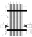
- FIG. 3 is an example of the tape fiber 96.
- the tape fiber 96 is made by combining two or more optical fibers 95 into a tape.
- an optical cable 84-1 is constructed by further bundling a tape fiber 96, which is a tape-shaped bundle of four optical fibers 95.
- the procedure for switching from the old communication building (OLT81#1) to the new communication building (OLT81#2) is as follows. First, as a preparation, the optical cable 84-1 to be cut is confirmed. At this time, communication between OLT 81 #1 and ONU 82 is maintained. The next step is to cut the optical cable 84-1 connecting the OLT 81#1 and the ONU 82. Naturally, communication will stop. Thereafter, the optical cable 84-2 is fusion-connected to the optical cable 84-1, and the OLT 81#2 and the ONU 82 are communicatively connected. Finally, communication between OLT 81#2 and ONU 82 starts, so confirm that communication has started.
- FIG. 5 shows the work process at the switching point PS.
- the optical fibers 95 are cut and connected, and the process will be described in detail.
- First step The optical fiber 95-1 is covered with a coating 94-1 to protect the glass portion 93-1. Therefore, the coating 94-1 of the optical fiber 95-1 is removed.
- a coating removal device which is a dedicated tool, is required. Removing the coating 94-1 reveals the glass.
- Second step Apply a blade to the glass portion 93-1 and cut it. When cutting, a special tool, a fiber cutter, is required.
- FIG. 6 is an explanatory diagram of a currently used coating removal device.
- the coating 94 is softened by applying a heater to the surface of the coating 94.
- a blade 25 made of metal or the like is applied to the softened coating 94, and the blade 25 is moved parallel to the longitudinal direction of the optical fiber 95. This allows the coating 94 to be peeled off.
- FIG. 7 is an explanatory diagram of a currently used fiber cutter. Both ends of the glass portion 93-1 are installed on the fixing base 21. When the press base 22 is moved upward from the bottom, the glass portion 93-1 is sandwiched between the metal blade 23 and the press base 22. By moving the metal blade 23 perpendicularly to the longitudinal direction of the glass portion 93-1, the metal blade 23 comes into contact with the glass portion 93-1 and scratches the glass portion 93-1. Due to the pressure from the pressing table 22, cracks appear in the scratched glass portion 93-1, and the optical fiber 95-1 is cut.
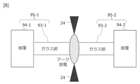
- FIG. 8 is an explanatory diagram of a currently used fusion splicing device.
- the glass parts 93-1 and 93-2 of the tape fiber are arranged to face each other and aligned with high precision. Thereafter, an electric discharge is generated from the electrode rod 24 to melt the glass portions 93-1 and 93-2, thereby connecting the optical fibers.
- a sheath stripping device, a fiber cutter, and a fusion splicing device are used to connect optical fibers.
- the time to work does not necessarily have to be bright daylight. We sometimes do construction work in the rain or snow.
- the environment in which construction takes place is not necessarily an easy environment for workers. In such an environment, it is a problem that while replacing multiple devices, the work cannot be completed unless the thin optical fiber is installed in the device without damaging it and the device is operated each time. Therefore, the present disclosure proposes a device that reduces the construction burden on workers.
- the metal blade 25 is used to scrape the coating 94-1 in the example shown in FIG.
- the fusion splicing device has a discharge function, and by using the discharge, the coating 94-1 can be melted. Therefore, in the present disclosure, the removal of the coating 94 is performed by the discharge function, thereby consolidating the removal into the fusion splicing device.
- the metal blade 23 and the press base 22 provided in the fiber cutter have a small number of parts and are small in size. Therefore, in the present disclosure, the fiber cutter may be housed in the casing of the fusion splicer.
- specific functions and operations provided in the device of the present disclosure will be described in detail.
- the device of this embodiment uses electrical discharge generated by the electrode rod to melt and remove the coating 94 by the electrical discharge.
- a temperature of 1300 degrees or higher is required.
- the coating 94 is made of an organic material, and a typical material is an ultraviolet curing resin. Ultraviolet curing resin easily melts when heated to 200 degrees. Therefore, by applying coating removal using electric discharge, it is possible to eliminate the coating removal device that was conventionally required. By setting the temperature for removing the coating between 200 degrees and 1000 degrees, only the coating can be removed without melting the glass.
- FIG. 9 shows an example of a configuration for removing the coating 94 using electric discharge.
- the figure shows an example in which the optical cable 84-1 is a tape fiber 96-1 that includes four glass parts 93-1-1 to 93-1-4.
- the tape fiber 84-1 is fixed using two fixing members 31, and the electrode rod 34 is moved near the tape fiber.
- the electrode rod 34 is moved along the optical cable 84-1 while discharging the electrode rod 32 (FIG. 9(c)). Thereby, a portion of the coating 94 in the longitudinal direction of the optical cable 84-1 can be removed.
- a camera is used to confirm whether the coating 94 has been removed. If by any chance the coating 94 remains, discharge and air blow are performed again until the soot is removed.
- FIGS. 10 and 11 show an example of the device configuration of the present disclosure.
- FIG. 10 is a side view
- FIG. 11 is a top view.
- the device of the present disclosure includes a fixing member 31, a metal blade 33, a press base 32, an electrode rod 34, an air blow 35, a camera 36, and a control section 37.
- the device of the present disclosure includes motors M31-1A, M31-1B, M33, which function as movable parts of the fixed members 31-1, 31-2, the metal blade 33 and the camera 36, the press base 32, and the electrode rod 34, respectively. Equipped with M32 and M34.
- the motor M32 functions as a press table movable section that moves the press table 32 to the surface of the glass portion 93-1.
- the motor M33 functions as a metal blade movable part that moves the metal blade 33 to the surface of the glass portion 93-1.
- the motor M34 functions as an electrode rod moving section that moves the electrode rod 34 in the longitudinal direction of the tape fiber 96
- the control unit 37 controls arbitrary operations in the device of the present disclosure. For example, the control unit 37 switches the temperature of the electrode rod 34 between a temperature of 1000° C. or more for performing fusion splicing and a temperature of 200° C. or more and less than 1000° C. for removing the coating. The temperature may be switched manually by the user, or automatically by the control unit 37.
- the device of the present disclosure can automatically change the connection from tape fiber 96-1 to tape fiber 96-2.
- the user installs the tape fibers 96-1 and 96-2 in the apparatus of the present disclosure and presses a start button provided on the apparatus of the present disclosure.
- the control unit 37 controls arbitrary functional units included in the device of the present disclosure to remove the coating from the tape fiber 96-1, cut the tape fiber 96-1, and cut the tape fiber 96-1 or 96-2.
- the movement and the fusion splicing of the tape fibers 96-1 and 96-2 are automatically executed in order.
- the fixing member 31-1 fixes the tape fiber 96-1 in a straight line at the center of the device. Both ends of this linear tape fiber 96-1 are connected to the ONU 82 and OLT 81#1 shown by.
- a fixing member 31-2 disposed below the fixing member 31-1 fixes the tape fiber 96-2 to be spliced.
- the coating 94-2 has already been removed from the tip of the tape fiber 96-2, and the glass portions 93-2-1 to 93-2-4 are exposed. Tape fiber 96-2 extends to OLT 81#2.
- FIG. 12 illustrates how the apparatus of the present disclosure cuts optical fiber.
- 12(a) and 12(c) show cross-sectional views
- FIG. 12(b) and FIG. 12(d) show top views.
- the metal blade 33 and the press base 32 are provided with motors M33 and M32 for position adjustment. After the coating 94-1 is removed by discharge, the metal blade 33 is brought into contact with the upper surface of the glass portion 93-1 using motors M33 and M32, as shown in FIGS. 12(a) and (b). Adjust the position of the metal blade 33 so that Next, the metal blade 33 comes into contact with the surface of the glass portion 93 and scratches it.
- the motor M31-2 connects the tape fiber 96-1B of OLT 82-#2 extending from the new communications building to the bottom of the tape fiber 96-1B from OLT 82-#1 extending from the old communications building. Place 96-2.
- the motor M31-1B connects the tape fiber 96-2 on the OLT81#1 side to the optical fiber 96-1A on the OLT81#1 side, as shown in FIG. 13(b). - Lower 1B back. This creates a space at the position of the tape fiber 96-1B, as shown in FIG. 13(c).
- the motor M31-2 moves the tape fiber 96-2 extending from the OLT 81#2 to that space. Further, the motor M31-2 aligns the tape fiber 96-2 extending from the OLT 81#2 with the tape fiber 96-1B with high precision.
- the above example shows an example in which the tape fiber 96-1B is moved backward, but the same effect can be obtained by shifting it laterally.
- the same effect can also be obtained by installing a motor M31-1A on the ONU 82 side and moving the tape fiber 96-1A up and down.
- the motor M34 moves the electrode rod 34 to align the tape fibers 96-1B and 96-2 in FIG. 13(d). Then, the electrode rod 34 generates a discharge. As a result, the end surfaces of the glass portions 93-1-1 to 93-1-4 of the tape fiber 96-1B and the glass portions 93-2-1 to 93-2-4 of the tape fiber 96-2 can be fused and spliced. .
- the electrode rod 34 has two functions: coating removal and fusion splicing.
- the method for removing the coating is as explained in FIG.
- the electrode rod 34 discharges from the horizontal direction of the glass parts 93-1-1 to 93-1-4 and the glass parts 93-2-1 to 93-2-4.
- fusion splicing is also performed by discharging horizontally, as shown in FIG. Perform fusion splicing in step 2-4. At this time, the motor M34 moves the electrode rod 34 to the connection position between the glass parts 93-1-1 to 93-1-4 and the glass parts 93-2-1 to 93-2-4.
- the apparatus of the present disclosure includes a motor M34 that moves the electrode rod 34 in the longitudinal direction of the tape fiber 96-1, as shown in FIG. 9(b).
- a motor M34 that moves the electrode rod 34 in the longitudinal direction of the tape fiber 96-1, as shown in FIG. 9(b).
- the camera 36 may be fixed to the same motor M33 as the metal blade 33, since a wider area can be seen by taking pictures from the top surface of the covering 94-1. Further, by arranging the camera 36 at the top, it is possible to visually check the alignment of the tape fibers 96-1A and 96-2 described in FIG. 13 with the camera 36.
- the present disclosure can incorporate the functions of coating removal, cutting, moving the fiber to be relocated, and fusion splicing into a single device.
- the apparatus of the present disclosure includes a control unit 37 that sequentially performs the operations of removing the coating, cutting, moving the fiber to be relocated, and fusion splicing.
- the device of the present disclosure fixes the tape fiber 96-1 to the fixing part 31-1 and fixes the tape fiber 96-2 to the fixing part 31-2, and then switches and connects the optical fibers with a single switch. A series of tasks can be carried out.
Abstract
One objective of the present disclosure is to enable a reduction in the number of equipment required in performing a series of operations to switch connection of optical fibers. The present disclosure is an apparatus characterised by including a pair of electrode rods for fusing, to connect, glass portions of optical fibers, the pair of electrode rods being used to remove coatings provided on the optical fibers.
Description
本開示は、光ファイバの切替を行う際に用いられる装置に関する。
The present disclosure relates to a device used when switching optical fibers.
光アクセス網では、ユーザにインターネット、電話のサービスを提供している。光アクセス網を構成する機器の交換を行う際、元々使用されていた機器から新たな機器へ、光ファイバの切替工事が行われる。移設元の光ファイバは通信に使用されているが、光ファイバの切替工事では、光ファイバの被覆を除去し、光ファイバを切断し、融着接続を行う(例えば、非特許文献2参照。)。
The optical access network provides Internet and telephone services to users. When replacing equipment that makes up an optical access network, optical fibers are switched from the originally used equipment to the new equipment. The original optical fiber is used for communications, but in the process of switching the optical fiber, the coating of the optical fiber is removed, the optical fiber is cut, and fusion spliced is performed (for example, see Non-Patent Document 2). .
光ファイバ1本のサイズは、ガラス部の外径が125μm、被覆の外径が250μmと細い。髪の毛1本とほぼ同じ太さである。このような微小なサイズである光ファイバを作業者自身が手に取り、装置にセットして、作業を行っている。
The size of one optical fiber is as small as the outer diameter of the glass portion of 125 μm and the outer diameter of the coating of 250 μm. It is approximately the same thickness as a single hair. An operator picks up such a microscopic optical fiber, sets it in a device, and performs the work.
現在の工事では、光ファイバの被覆の除去、光ファイバの切断、及び融着接続において、個別の装置を用いている。装置を取り換える際には、作業者の注意が光ファイバから逸れることになる。さらに、作業を時間は、明るい日中とも限らない。雨の中、雪の中、工事をすることもある。工事をする環境が必ずしも作業者にとってやりやすい環境ではない。このため、工事の途中で装置を取り換える際に、光ファイバを折損することもあった。そのような環境下の中で、複数台の装置がないと工事が完了しないことは課題である。
Current construction uses separate equipment for stripping optical fibers, cutting optical fibers, and fusion splicing. When replacing equipment, the operator's attention is diverted from the optical fiber. Furthermore, the time to work does not necessarily have to be during bright daylight hours. We sometimes do construction work in the rain or snow. The environment in which construction takes place is not necessarily an easy environment for workers. For this reason, when replacing equipment during construction, optical fibers could sometimes be broken. In such an environment, the problem is that construction work cannot be completed without multiple devices.
本開示は、光ファイバの切替接続の一連の作業を行う際に必要な装置を減少可能にすることを目的とする。
An object of the present disclosure is to make it possible to reduce the number of devices required when performing a series of operations for switching and connecting optical fibers.
本開示の装置は、光ファイバを繋ぎ変えるための装置であって、光ファイバに備わるガラス部を融着接続する一対の電極棒を備え、前記一対の電極棒を用いて、前記光ファイバに備わる被覆を除去することを特徴とする。例えば、本開示の装置は、前記一対の電極棒が、1000℃以上の温度と、200℃以上1000℃未満の温度と、で切り替え可能である。
The device of the present disclosure is a device for reconnecting optical fibers, and includes a pair of electrode rods for fusion splicing the glass portions of the optical fibers, and uses the pair of electrode rods to connect the glass portions of the optical fibers. It is characterized by removing the coating. For example, in the device of the present disclosure, the pair of electrode rods can be switched between a temperature of 1000°C or higher and a temperature of 200°C or higher and lower than 1000°C.
本開示の方法は、本開示の装置が実行する方法であって、前記一対の電極棒を用いて、第1の光ファイバに備わる被覆を除去し、前記一対の電極棒を用いて、前記第1の光ファイバに備わるガラス部と第2の光ファイバに備わるガラス部とを融着接続する。
The method of the present disclosure is a method carried out by the apparatus of the present disclosure, in which a coating provided on a first optical fiber is removed using the pair of electrode rods, and a covering of the first optical fiber is removed using the pair of electrode rods. A glass portion of one optical fiber and a glass portion of a second optical fiber are fusion-spliced.
ここで、前記第1の光ファイバ及び前記第2の光ファイバが、異なる位置に配置されている通信ビルから伸びる光ファイバでありうる。このように、本開示の装置は、第1の光ファイバから第2の光ファイバへの切替接続の作業を行うことができる。
Here, the first optical fiber and the second optical fiber may be optical fibers extending from communication buildings located at different locations. Thus, the apparatus of the present disclosure can perform the task of switching connections from a first optical fiber to a second optical fiber.
本開示の装置は、前記一対の電極棒を、前記第1の光ファイバの長手方向に移動させる電極棒可動台を備えていてもよい。また、本開示の装置は、前記一対の電極棒が前記被覆を溶解させ、前記被覆の溶解によって生じた煤を除去するエアブローを備えていてもよい。さらに、本開示の装置は、煤が除去できているかを確認できるよう、前記一対の電極棒によって露出した前記ガラス部を撮像するカメラを備えていてもよい。
The apparatus of the present disclosure may include an electrode rod movable base that moves the pair of electrode rods in the longitudinal direction of the first optical fiber. Further, the device of the present disclosure may include an air blow that causes the pair of electrode rods to melt the coating and remove soot generated by the melting of the coating. Furthermore, the apparatus of the present disclosure may include a camera that images the glass portion exposed by the pair of electrode rods so as to confirm whether soot has been removed.
本開示の方法は、前記第1の光ファイバの長手方向に並行して、前記一対の電極棒から放電することで、前記第1の光ファイバの被覆を前記第1の光ファイバの長手方向に除去し、前記第1の光ファイバの被覆の除去後に、エアブローで表面に残った煤を取り除き、さらに、前記被覆が除去されることによって露出した前記第1の光ファイバのガラス部を、カメラでモニタする。
The method of the present disclosure includes discharging the coating of the first optical fiber in the longitudinal direction of the first optical fiber by discharging from the pair of electrode rods in parallel with the longitudinal direction of the first optical fiber. After removing the coating of the first optical fiber, the soot remaining on the surface of the first optical fiber is removed by air blowing, and the glass portion of the first optical fiber exposed by removing the coating is photographed with a camera. Monitor.
本開示の装置は、前記ガラス部のうちの前記金属刃の配置されている側面と対向する側面で、前記ガラス部を押さえる押圧台と、前記金属刃を前記ガラス部の表面に移動させる金属刃可動部と、を備えていてもよい。これにより、第1の光ファイバから第2の光ファイバへの切替接続の一連の作業を、1台の装置で行うことができる。
The device of the present disclosure includes a press base that presses the glass portion on a side surface of the glass portion that faces the side surface where the metal blade is arranged, and a metal blade that moves the metal blade to the surface of the glass portion. A movable part may be provided. Thereby, a series of operations for switching and connecting the first optical fiber to the second optical fiber can be performed with one device.
なお、上記各開示は、可能な限り組み合わせることができる。
Note that the above disclosures can be combined as much as possible.
本開示は、光ファイバの切替接続の一連の作業を行う際に必要な装置の台数を減少させることができる。このため、本開示は、作業者への工事負担を低減させ、作業効率を向上することができる。
The present disclosure can reduce the number of devices required when performing a series of operations for switching and connecting optical fibers. Therefore, the present disclosure can reduce the construction burden on workers and improve work efficiency.
以下、本開示の実施形態について、図面を参照しながら詳細に説明する。なお、本開示は、以下に示す実施形態に限定されるものではない。これらの実施の例は例示に過ぎず、本開示は当業者の知識に基づいて種々の変更、改良を施した形態で実施することができる。なお、本明細書及び図面において符号が同じ構成要素は、相互に同一のものを示すものとする。
Hereinafter, embodiments of the present disclosure will be described in detail with reference to the drawings. Note that the present disclosure is not limited to the embodiments shown below. These implementation examples are merely illustrative, and the present disclosure can be implemented with various changes and improvements based on the knowledge of those skilled in the art. Note that components with the same reference numerals in this specification and the drawings indicate the same components.
光アクセス網では、図1に示す設備を提供することで、ユーザにインターネット、電話のサービスを提供している。通信ビルに通信機器である光加入者線終端装置(Optical Line Terminal:OLT)81を設置し、ユーザ宅内に光加入者線ネットワーク装置(Optical Network Unit:ONU)82を設置している。OLT81とONU82は、IDM83、光ケーブル84-1、スプリッタ85を用いて接続している。通信光として、OLT81側から波長1490nm,1550nmを出力し、ONU82側から波長1310nmを出力することで、OLT81とONU82が互いを認識し、ユーザにインターネット、電話などの高速ブロードバンドサービスを提供している。
The optical access network provides Internet and telephone services to users by providing the equipment shown in Figure 1. An optical line terminal (OLT) 81, which is communication equipment, is installed in a communication building, and an optical network unit (ONU) 82 is installed in a user's home. The OLT 81 and ONU 82 are connected using an IDM 83, an optical cable 84-1, and a splitter 85. By outputting wavelengths of 1490 nm and 1550 nm from the OLT 81 side and outputting a wavelength of 1310 nm from the ONU 82 side as communication light, the OLT 81 and ONU 82 recognize each other and provide high-speed broadband services such as the Internet and telephone to users. .
図2は、OLT81とONU82を結んでいる光ファイバ95の構造を示す。光ファイバ95は、コアガラス91とその周囲を覆うクラッドガラス92から構成されるガラス部93、ガラス部93を保護するための被覆94の3層構造を備える。コアガラス91は純石英ガラスが主成分で、添加物として二酸化ゲルマニウムが用いられている。二酸化ゲルマニウムを添加することで屈折率を高くしている。一方で、クラッドガラス92は純石英ガラスのみで構成することで、クラッドガラス92はコアガラス91よりも低い屈折率になるように設計している。コアガラス91とクラッドガラス92で屈折率が異なるため、境界面で全反射が生じ通信光がコアガラス91内を伝搬する。
FIG. 2 shows the structure of an optical fiber 95 connecting the OLT 81 and ONU 82. The optical fiber 95 has a three-layer structure including a glass portion 93 consisting of a core glass 91 and a clad glass 92 surrounding the core glass, and a coating 94 for protecting the glass portion 93. The main component of the core glass 91 is pure silica glass, and germanium dioxide is used as an additive. The refractive index is increased by adding germanium dioxide. On the other hand, the clad glass 92 is designed to have a lower refractive index than the core glass 91 by being made of only pure silica glass. Since the core glass 91 and the cladding glass 92 have different refractive indexes, total reflection occurs at the interface and communication light propagates within the core glass 91 .
図3は、テープファイバ96の一例である。テープファイバ96は、2本以上の光ファイバ95をまとめてテープ化したものである。本実施形態では、4本の光ファイバ95をテープ状に束ねたテープファイバ96を、さらに束ねて光ケーブル84-1が構成されている。(非特許文献1)
FIG. 3 is an example of the tape fiber 96. The tape fiber 96 is made by combining two or more optical fibers 95 into a tape. In this embodiment, an optical cable 84-1 is constructed by further bundling a tape fiber 96, which is a tape-shaped bundle of four optical fibers 95. (Non-patent document 1)
通信ビルは、建築されてから時間が経過しているため、ビルそのものが劣化する。例えば、事象として、コンクリートがひび割れ、そのひび割れから水分が入ってくる。通信ビル内には、例えば、OLT81に示すような通信機器が大量に設置されている。通信機器は電力を動力として動いている。水分が通信ビル内に入り、通信機器に触れると、装置に影響を与え、最悪、止まることも考えられる。つまり、ユーザにサービスを提供できなくなる。
Because it has been a long time since the telecommunications building was constructed, the building itself deteriorates. For example, an event may occur when concrete cracks and water enters through the cracks. For example, a large number of communication devices as shown in OLT 81 are installed in the communication building. Communication equipment is powered by electricity. If moisture enters a telecommunications building and touches telecommunications equipment, it could affect the equipment and, in the worst case, cause it to stop working. In other words, it becomes impossible to provide services to users.
そこで、対策として、図4に示すように、新たな通信ビルを構築し、その新通信ビルに新しくOLT81#2を設置して、OLT81#2からの光信号によるサービスを提供したい。そのためには、OLT81#1から伸びる光ケーブル84-1を切断し、新しい光ケーブル84-2に切り替えなくてはならない。
Therefore, as a countermeasure, as shown in FIG. 4, we would like to construct a new communication building, install a new OLT 81#2 in the new communication building, and provide services using optical signals from OLT 81#2. To do this, it is necessary to cut the optical cable 84-1 extending from the OLT 81#1 and switch to a new optical cable 84-2.
旧通信ビル(OLT81#1)から新通信ビル(OLT81#2)へ切替の手順は以下のとおりである。
まず、準備として、切断する光ケーブル84-1を確認する。この時は、OLT81#1とONU82の通信は維持されている。
次の工程は、OLT81#1とONU82を結んでいる光ケーブル84-1を切断する。当然、通信は止まる。
その後、光ケーブル84-2を光ケーブル84-1と融着接続し、OLT81#2とONU82を通信接続する。
最後に、OLT81#2とONU82の通信が始まるので、通信を開始したことを確認する。 The procedure for switching from the old communication building (OLT81#1) to the new communication building (OLT81#2) is as follows.
First, as a preparation, the optical cable 84-1 to be cut is confirmed. At this time, communication betweenOLT 81 #1 and ONU 82 is maintained.
The next step is to cut the optical cable 84-1 connecting theOLT 81#1 and the ONU 82. Naturally, communication will stop.
Thereafter, the optical cable 84-2 is fusion-connected to the optical cable 84-1, and theOLT 81#2 and the ONU 82 are communicatively connected.
Finally, communication betweenOLT 81#2 and ONU 82 starts, so confirm that communication has started.
まず、準備として、切断する光ケーブル84-1を確認する。この時は、OLT81#1とONU82の通信は維持されている。
次の工程は、OLT81#1とONU82を結んでいる光ケーブル84-1を切断する。当然、通信は止まる。
その後、光ケーブル84-2を光ケーブル84-1と融着接続し、OLT81#2とONU82を通信接続する。
最後に、OLT81#2とONU82の通信が始まるので、通信を開始したことを確認する。 The procedure for switching from the old communication building (OLT81#1) to the new communication building (OLT81#2) is as follows.
First, as a preparation, the optical cable 84-1 to be cut is confirmed. At this time, communication between
The next step is to cut the optical cable 84-1 connecting the
Thereafter, the optical cable 84-2 is fusion-connected to the optical cable 84-1, and the
Finally, communication between
図5は切替ポイントPSでの作業工程を示す。切替をするには、光ファイバ95を切断して、つなげることを行うが、その工程を詳しく示す。
(1)第1のステップ
光ファイバ95-1は、ガラス部93-1を守るため、被覆94-1で覆われている。そこで、光ファイバ95-1の被覆94-1を除去する。被覆94-1を除去するためには、専用の工具となる被覆除去装置が必要である。被覆94-1を除去するとガラスが現れる。
(2)第2のステップ
ガラス部93-1に刃を当てて、切断をする。切断をするときにも、専用の工具となるファイバカッターが必要である。
(3)第3のステップ
移設先光ファイバ95-2の移動、つまり新通信ビルから伸びてきている光ケーブル84-2の光ファイバ95-2を、移設元の光ケーブル84-1の光ファイバ95-1に接続する。
(4)第4のステップ
そして、光ファイバ95-1及び95-2を専用の工具となる融着接続装置を用いて接続する。
(5)第5のステップ
接続後、OLT81#2とONU82の通信を開始する。
このように、光ファイバ切替を行うためには、被覆除去、切断、移設先ファイバの移動、融着接続といった複数の工程と、被覆除去装置、ファイバカッター及び融着接続装置が必要である。 FIG. 5 shows the work process at the switching point PS. To perform switching, theoptical fibers 95 are cut and connected, and the process will be described in detail.
(1) First step The optical fiber 95-1 is covered with a coating 94-1 to protect the glass portion 93-1. Therefore, the coating 94-1 of the optical fiber 95-1 is removed. In order to remove the coating 94-1, a coating removal device, which is a dedicated tool, is required. Removing the coating 94-1 reveals the glass.
(2) Second step Apply a blade to the glass portion 93-1 and cut it. When cutting, a special tool, a fiber cutter, is required.
(3) Third step: Moving the destination optical fiber 95-2, that is, moving the optical fiber 95-2 of the optical cable 84-2 extending from the new communication building to the optical fiber 95-2 of the source optical cable 84-1. Connect to 1.
(4) Fourth step Then, the optical fibers 95-1 and 95-2 are connected using a fusion splicing device which is a special tool.
(5) Fifth step After connection, communication betweenOLT 81 #2 and ONU 82 is started.
As described above, in order to switch optical fibers, a plurality of steps such as removing the coating, cutting, moving the fiber to be relocated, and fusion splicing, as well as a coating removing device, a fiber cutter, and a fusion splicing device are required.
(1)第1のステップ
光ファイバ95-1は、ガラス部93-1を守るため、被覆94-1で覆われている。そこで、光ファイバ95-1の被覆94-1を除去する。被覆94-1を除去するためには、専用の工具となる被覆除去装置が必要である。被覆94-1を除去するとガラスが現れる。
(2)第2のステップ
ガラス部93-1に刃を当てて、切断をする。切断をするときにも、専用の工具となるファイバカッターが必要である。
(3)第3のステップ
移設先光ファイバ95-2の移動、つまり新通信ビルから伸びてきている光ケーブル84-2の光ファイバ95-2を、移設元の光ケーブル84-1の光ファイバ95-1に接続する。
(4)第4のステップ
そして、光ファイバ95-1及び95-2を専用の工具となる融着接続装置を用いて接続する。
(5)第5のステップ
接続後、OLT81#2とONU82の通信を開始する。
このように、光ファイバ切替を行うためには、被覆除去、切断、移設先ファイバの移動、融着接続といった複数の工程と、被覆除去装置、ファイバカッター及び融着接続装置が必要である。 FIG. 5 shows the work process at the switching point PS. To perform switching, the
(1) First step The optical fiber 95-1 is covered with a coating 94-1 to protect the glass portion 93-1. Therefore, the coating 94-1 of the optical fiber 95-1 is removed. In order to remove the coating 94-1, a coating removal device, which is a dedicated tool, is required. Removing the coating 94-1 reveals the glass.
(2) Second step Apply a blade to the glass portion 93-1 and cut it. When cutting, a special tool, a fiber cutter, is required.
(3) Third step: Moving the destination optical fiber 95-2, that is, moving the optical fiber 95-2 of the optical cable 84-2 extending from the new communication building to the optical fiber 95-2 of the source optical cable 84-1. Connect to 1.
(4) Fourth step Then, the optical fibers 95-1 and 95-2 are connected using a fusion splicing device which is a special tool.
(5) Fifth step After connection, communication between
As described above, in order to switch optical fibers, a plurality of steps such as removing the coating, cutting, moving the fiber to be relocated, and fusion splicing, as well as a coating removing device, a fiber cutter, and a fusion splicing device are required.
図6は、現在用いられている被覆除去装置の説明図である。図6(a)に示すように、被覆94の表面にヒータを当てることで、被覆94を柔らかくする。その後、図6(b)に示すように、柔らかくなった被覆94に金属製等の刃25を当てて、その刃25を光ファイバ95の長手方向と平行に移動する。これにより、被覆94を剥がすことができる。
FIG. 6 is an explanatory diagram of a currently used coating removal device. As shown in FIG. 6(a), the coating 94 is softened by applying a heater to the surface of the coating 94. Thereafter, as shown in FIG. 6(b), a blade 25 made of metal or the like is applied to the softened coating 94, and the blade 25 is moved parallel to the longitudinal direction of the optical fiber 95. This allows the coating 94 to be peeled off.
図7は、現在用いられているファイバカッターの説明図である。ガラス部93-1の両端を固定台21に設置する。押圧台22を下から上方向に移動すると、ガラス部93-1は金属の刃23と押圧台22に挟まれる。金属の刃23をガラス部93-1の長手方向と垂直に移動させることで、ガラス部93-1に金属製の刃23を接触させ、ガラス部93-1に傷を付ける。押圧台22からの圧がかかっているため、傷を付けたガラス部93-1にひびがはいり、光ファイバ95-1が切断される。
FIG. 7 is an explanatory diagram of a currently used fiber cutter. Both ends of the glass portion 93-1 are installed on the fixing base 21. When the press base 22 is moved upward from the bottom, the glass portion 93-1 is sandwiched between the metal blade 23 and the press base 22. By moving the metal blade 23 perpendicularly to the longitudinal direction of the glass portion 93-1, the metal blade 23 comes into contact with the glass portion 93-1 and scratches the glass portion 93-1. Due to the pressure from the pressing table 22, cracks appear in the scratched glass portion 93-1, and the optical fiber 95-1 is cut.
図8は、現在用いられている融着接続装置の説明図である。テープファイバのガラス部93-1及び93-2を対向になるように配置させ、高精度に位置を合わせる。その後、電極棒24から放電をし、ガラス部93-1及び93-2を溶かすことで、光ファイバ同士を接続させる。
FIG. 8 is an explanatory diagram of a currently used fusion splicing device. The glass parts 93-1 and 93-2 of the tape fiber are arranged to face each other and aligned with high precision. Thereafter, an electric discharge is generated from the electrode rod 24 to melt the glass portions 93-1 and 93-2, thereby connecting the optical fibers.
現在の工事では、光ファイバを接続するためには、被覆除去装置、ファイバカッター及び融着接続装置を用いている。作業を時間は、明るい日中とも限らない。雨の中、雪の中、工事をすることもある。工事をする環境が必ずしも作業者にとってやりやすい環境ではない。そのような環境下でこのような複数台の装置を取り換えながら、作業の都度、細い光ファイバを傷つけることなく装置に設置し、装置を操作しないと工事が完了しないことは課題である。そこで、本開示は、作業者への工事負担を低減させる装置を提案する。
In current construction, a sheath stripping device, a fiber cutter, and a fusion splicing device are used to connect optical fibers. The time to work does not necessarily have to be bright daylight. We sometimes do construction work in the rain or snow. The environment in which construction takes place is not necessarily an easy environment for workers. In such an environment, it is a problem that while replacing multiple devices, the work cannot be completed unless the thin optical fiber is installed in the device without damaging it and the device is operated each time. Therefore, the present disclosure proposes a device that reduces the construction burden on workers.
(本開示の概要)
被覆94-1の除去のために、図6の例では金属の刃25を用いて被覆94-1を削っていることを述べた。しかし、融着接続装置には、放電機能があり、その放電を用いることで、被覆94-1を溶解させることができる。そこで、本開示では、被覆94の除去を放電機能が実施することで、融着接続装置に集約する。 (Summary of this disclosure)
As described above, in order to remove the coating 94-1, themetal blade 25 is used to scrape the coating 94-1 in the example shown in FIG. However, the fusion splicing device has a discharge function, and by using the discharge, the coating 94-1 can be melted. Therefore, in the present disclosure, the removal of the coating 94 is performed by the discharge function, thereby consolidating the removal into the fusion splicing device.
被覆94-1の除去のために、図6の例では金属の刃25を用いて被覆94-1を削っていることを述べた。しかし、融着接続装置には、放電機能があり、その放電を用いることで、被覆94-1を溶解させることができる。そこで、本開示では、被覆94の除去を放電機能が実施することで、融着接続装置に集約する。 (Summary of this disclosure)
As described above, in order to remove the coating 94-1, the
また、ファイバカッターに備わる金属の刃23と押圧台22は、部品の数が少なく、部品のサイズが小さい。そこで、本開示では、融着接続装置の筐体に、ファイバカッターを収容してもよい。
以下、本開示の装置に備わる具体的な機能及び動作について、詳細に説明する。 Further, themetal blade 23 and the press base 22 provided in the fiber cutter have a small number of parts and are small in size. Therefore, in the present disclosure, the fiber cutter may be housed in the casing of the fusion splicer.
Hereinafter, specific functions and operations provided in the device of the present disclosure will be described in detail.
以下、本開示の装置に備わる具体的な機能及び動作について、詳細に説明する。 Further, the
Hereinafter, specific functions and operations provided in the device of the present disclosure will be described in detail.
(実施形態例1)
本実施形態の装置は、電極棒で生じる放電を用い、放電により、被覆94を溶かして除去する。融着接続においてガラスを溶かすためには1300度以上が必要である。 (Embodiment example 1)
The device of this embodiment uses electrical discharge generated by the electrode rod to melt and remove thecoating 94 by the electrical discharge. In order to melt the glass in fusion splicing, a temperature of 1300 degrees or higher is required.
本実施形態の装置は、電極棒で生じる放電を用い、放電により、被覆94を溶かして除去する。融着接続においてガラスを溶かすためには1300度以上が必要である。 (Embodiment example 1)
The device of this embodiment uses electrical discharge generated by the electrode rod to melt and remove the
一方で、被覆94は有機材料で構成されており、代表的な材料として、紫外線硬化樹脂が挙げられる。紫外線硬化樹脂は、200度まで加熱をすれば、容易に溶解する。このため、放電を用いた被覆除去を適用することで、従来必要であった被覆除去装置をなくすことができる。被覆を除去するための温度は、200度から1000度に設定することで、ガラスを溶かすことなく、被覆のみを除去できる。
On the other hand, the coating 94 is made of an organic material, and a typical material is an ultraviolet curing resin. Ultraviolet curing resin easily melts when heated to 200 degrees. Therefore, by applying coating removal using electric discharge, it is possible to eliminate the coating removal device that was conventionally required. By setting the temperature for removing the coating between 200 degrees and 1000 degrees, only the coating can be removed without melting the glass.
図9に、放電を用いて被覆94を除去するための構成例を示す。図では、光ケーブル84-1が4本のガラス部93-1-1~93-1-4を内包したテープファイバ96-1である例を示す。
2つの固定部材31を用いて、テープファイバ84-1を固定し、電極棒34をテープファイバ付近に移動させる図9(a)。
次に、極棒32を放電させながら、電極棒34を光ケーブル84-1に沿って移動する(図9(c))。これにより、被覆94を光ケーブル84-1の長手方向の一部を除去することができる。 FIG. 9 shows an example of a configuration for removing thecoating 94 using electric discharge. The figure shows an example in which the optical cable 84-1 is a tape fiber 96-1 that includes four glass parts 93-1-1 to 93-1-4.
In FIG. 9(a), the tape fiber 84-1 is fixed using two fixing members 31, and theelectrode rod 34 is moved near the tape fiber.
Next, theelectrode rod 34 is moved along the optical cable 84-1 while discharging the electrode rod 32 (FIG. 9(c)). Thereby, a portion of the coating 94 in the longitudinal direction of the optical cable 84-1 can be removed.
2つの固定部材31を用いて、テープファイバ84-1を固定し、電極棒34をテープファイバ付近に移動させる図9(a)。
次に、極棒32を放電させながら、電極棒34を光ケーブル84-1に沿って移動する(図9(c))。これにより、被覆94を光ケーブル84-1の長手方向の一部を除去することができる。 FIG. 9 shows an example of a configuration for removing the
In FIG. 9(a), the tape fiber 84-1 is fixed using two fixing members 31, and the
Next, the
ここで、高温により、被覆94のみを除去するが、被覆94の一部が煤状になり、ガラス部93の表面に残る可能性がある。その煤を落とすために、ガラス部93の露出部分にエアーを噴射し、落とす(図9(d))。
Here, only the coating 94 is removed due to the high temperature, but there is a possibility that a part of the coating 94 becomes soot-like and remains on the surface of the glass portion 93. In order to remove the soot, air is injected onto the exposed portion of the glass portion 93 to remove it (FIG. 9(d)).
そして、最後にカメラを用いて、被覆94が除去されたかについて確認する。万が一、被覆94が残った場合は、再度、放電とエアブローを行い、煤が落ちるまで繰り返す。
Finally, a camera is used to confirm whether the coating 94 has been removed. If by any chance the coating 94 remains, discharge and air blow are performed again until the soot is removed.
図10及び図11に、本開示の装置構成の一例を示す。図10が側面図、図11が上面図である。本開示の装置は、固定部材31、金属刃33、押圧台32、電極棒34、エアブロー35、カメラ36、制御部37を備える。また本開示の装置は、固定部材31-1,31-2、金属刃33及びカメラ36、押圧台32、電極棒34のそれぞれの可動部として機能するモータM31-1A,M31-1B、M33、M32、M34を備える。モータM32は、押圧台32をガラス部93-1の表面に移動させる押圧台可動部として機能する。モータM33は、金属刃33をガラス部93-1の表面に移動させる金属刃可動部として機能する。モータM34は、電極棒34をテープファイバ96-1の長手方向に移動させる電極棒可動部として機能する。
FIGS. 10 and 11 show an example of the device configuration of the present disclosure. FIG. 10 is a side view, and FIG. 11 is a top view. The device of the present disclosure includes a fixing member 31, a metal blade 33, a press base 32, an electrode rod 34, an air blow 35, a camera 36, and a control section 37. Further, the device of the present disclosure includes motors M31-1A, M31-1B, M33, which function as movable parts of the fixed members 31-1, 31-2, the metal blade 33 and the camera 36, the press base 32, and the electrode rod 34, respectively. Equipped with M32 and M34. The motor M32 functions as a press table movable section that moves the press table 32 to the surface of the glass portion 93-1. The motor M33 functions as a metal blade movable part that moves the metal blade 33 to the surface of the glass portion 93-1. The motor M34 functions as an electrode rod moving section that moves the electrode rod 34 in the longitudinal direction of the tape fiber 96-1.
制御部37は、本開示の装置における任意の動作を制御する。例えば、制御部37は、電極棒34の温度を、融着接続を行うための1000℃以上の温度と、被覆除去を行うための200℃以上1000℃未満の温度と、で切り替える。温度の切り替えは、ユーザの手動で行ってもよいが、制御部37が自動で行ってもよい。
The control unit 37 controls arbitrary operations in the device of the present disclosure. For example, the control unit 37 switches the temperature of the electrode rod 34 between a temperature of 1000° C. or more for performing fusion splicing and a temperature of 200° C. or more and less than 1000° C. for removing the coating. The temperature may be switched manually by the user, or automatically by the control unit 37.
本開示の装置は、テープファイバ96-1からテープファイバ96-2への繋ぎ変えが自動で可能である。自動で行う場合、ユーザが、テープファイバ96-1及び96-2を本開示の装置に設置し、本開示の装置に備わるスタートボタンを押す。すると、制御部37は、本開示の装置に備わる任意の機能部を制御することで、テープファイバ96-1の被覆除去、テープファイバ96-1の切断、テープファイバ96-1又は96-2の移動、テープファイバ96-1及び96-2の融着接続、を順に自動で実行する。
The device of the present disclosure can automatically change the connection from tape fiber 96-1 to tape fiber 96-2. In the case of automatic operation, the user installs the tape fibers 96-1 and 96-2 in the apparatus of the present disclosure and presses a start button provided on the apparatus of the present disclosure. Then, the control unit 37 controls arbitrary functional units included in the device of the present disclosure to remove the coating from the tape fiber 96-1, cut the tape fiber 96-1, and cut the tape fiber 96-1 or 96-2. The movement and the fusion splicing of the tape fibers 96-1 and 96-2 are automatically executed in order.
(本開示の装置への光ファイバの設置)
固定部材31-1は、装置内の中心でテープファイバ96-1を直線状に固定する。この直線状のテープファイバ96-1の両端は、で示すONU82とOLT81#1がつながっている。固定部材31-1の下側に配置されている固定部材31-2は、つなぎ変えるテープファイバ96-2を固定する。テープファイバ96-2の先端は、既に被覆94-2が除去され、ガラス部93-2-1~93-2-4が露出している。テープファイバ96-2は、OLT81#2へ伸びている。 (Installation of optical fiber to the device of the present disclosure)
The fixing member 31-1 fixes the tape fiber 96-1 in a straight line at the center of the device. Both ends of this linear tape fiber 96-1 are connected to theONU 82 and OLT 81#1 shown by. A fixing member 31-2 disposed below the fixing member 31-1 fixes the tape fiber 96-2 to be spliced. The coating 94-2 has already been removed from the tip of the tape fiber 96-2, and the glass portions 93-2-1 to 93-2-4 are exposed. Tape fiber 96-2 extends to OLT 81#2.
固定部材31-1は、装置内の中心でテープファイバ96-1を直線状に固定する。この直線状のテープファイバ96-1の両端は、で示すONU82とOLT81#1がつながっている。固定部材31-1の下側に配置されている固定部材31-2は、つなぎ変えるテープファイバ96-2を固定する。テープファイバ96-2の先端は、既に被覆94-2が除去され、ガラス部93-2-1~93-2-4が露出している。テープファイバ96-2は、OLT81#2へ伸びている。 (Installation of optical fiber to the device of the present disclosure)
The fixing member 31-1 fixes the tape fiber 96-1 in a straight line at the center of the device. Both ends of this linear tape fiber 96-1 are connected to the
(光ファイバの切断)
図12は、本開示の装置が光ファイバを切断する方法を示す。図12(a)と図12(c)は断面図を示し、図12(b)と図12(d)は上面図を示す。金属刃33と押圧台32には位置を調整するためのモータM33及びM32がついている。
放電による被覆94-1が除去されたあとに、図12(a)及び(b)に示すように、モータM33及びM32を用いて、金属刃33がガラス部93-1の上の表面に接触するように、金属刃33の位置調整をする。
次に、金属刃33がガラス部93の表面に接触し、傷をつける。このとき、金属刃33をガラス部93-1の長手方向と垂直に動かすことで(図12(b))、ガラス部93-1-1~93-1-4の表面に傷をつける。
その後、テープファイバ96-1の下側にある押圧台32がモータM32により上部に移動することで、テープファイバ96-1を押し付ける。ガラス部93-1-1~93-1-4の表面には傷がすでにあるため、その傷からガラス部93-1-1~93-1-4すなわちテープファイバ96-1が切断される。 (cutting of optical fiber)
FIG. 12 illustrates how the apparatus of the present disclosure cuts optical fiber. 12(a) and 12(c) show cross-sectional views, and FIG. 12(b) and FIG. 12(d) show top views. Themetal blade 33 and the press base 32 are provided with motors M33 and M32 for position adjustment.
After the coating 94-1 is removed by discharge, themetal blade 33 is brought into contact with the upper surface of the glass portion 93-1 using motors M33 and M32, as shown in FIGS. 12(a) and (b). Adjust the position of the metal blade 33 so that
Next, themetal blade 33 comes into contact with the surface of the glass portion 93 and scratches it. At this time, by moving the metal blade 33 perpendicularly to the longitudinal direction of the glass portion 93-1 (FIG. 12(b)), the surfaces of the glass portions 93-1-1 to 93-1-4 are scratched.
Thereafter, thepress base 32 below the tape fiber 96-1 is moved upward by the motor M32, thereby pressing the tape fiber 96-1. Since scratches are already present on the surfaces of the glass parts 93-1-1 to 93-1-4, the glass parts 93-1-1 to 93-1-4, that is, the tape fiber 96-1, are cut from the scratches.
図12は、本開示の装置が光ファイバを切断する方法を示す。図12(a)と図12(c)は断面図を示し、図12(b)と図12(d)は上面図を示す。金属刃33と押圧台32には位置を調整するためのモータM33及びM32がついている。
放電による被覆94-1が除去されたあとに、図12(a)及び(b)に示すように、モータM33及びM32を用いて、金属刃33がガラス部93-1の上の表面に接触するように、金属刃33の位置調整をする。
次に、金属刃33がガラス部93の表面に接触し、傷をつける。このとき、金属刃33をガラス部93-1の長手方向と垂直に動かすことで(図12(b))、ガラス部93-1-1~93-1-4の表面に傷をつける。
その後、テープファイバ96-1の下側にある押圧台32がモータM32により上部に移動することで、テープファイバ96-1を押し付ける。ガラス部93-1-1~93-1-4の表面には傷がすでにあるため、その傷からガラス部93-1-1~93-1-4すなわちテープファイバ96-1が切断される。 (cutting of optical fiber)
FIG. 12 illustrates how the apparatus of the present disclosure cuts optical fiber. 12(a) and 12(c) show cross-sectional views, and FIG. 12(b) and FIG. 12(d) show top views. The
After the coating 94-1 is removed by discharge, the
Next, the
Thereafter, the
(移設先の光ファイバの移動)
テープファイバ96-1が切断された後、図13に示すように、OLT81#1からOLT81#2へ切り替える。
まず、図13(a)に示すように、モータM31-2は、古い通信ビルから伸びるOLT82#1からのテープファイバ96-1Bの下側に、新しい通信ビルから伸びるOLT82-#2のテープファイバ96-2を配置する。
次に、OLT82#2側のテープファイバ96-2とONU82の光ファイバ96-1Aを接続したいため、図13(b)に示すように、モータM31-1Bは、OLT81#1側のテープファイバ96-1Bを後ろへ下げる。これにより、図13(c)に示すように、テープファイバ96-1Bの位置にスペースができる。
次に、図13(d)に示すように、モータM31-2は、OLT81#2から伸びるテープファイバ96-2をそのスペースに移動させる。さらに、モータM31-2は、OLT81#2から伸びるテープファイバ96-2を、高精度に、テープファイバ96-1Bと位置を合わせる。 (Movement of optical fiber at relocation destination)
After the tape fiber 96-1 is cut, as shown in FIG. 13, theOLT 81#1 is switched to the OLT 81#2.
First, as shown in FIG. 13(a), the motor M31-2 connects the tape fiber 96-1B of OLT 82-#2 extending from the new communications building to the bottom of the tape fiber 96-1B from OLT 82-#1 extending from the old communications building. Place 96-2.
Next, since it is desired to connect the tape fiber 96-2 on theOLT82# 2 side and the optical fiber 96-1A of the ONU82, the motor M31-1B connects the tape fiber 96-2 on the OLT81# 1 side to the optical fiber 96-1A on the OLT81# 1 side, as shown in FIG. 13(b). - Lower 1B back. This creates a space at the position of the tape fiber 96-1B, as shown in FIG. 13(c).
Next, as shown in FIG. 13(d), the motor M31-2 moves the tape fiber 96-2 extending from theOLT 81#2 to that space. Further, the motor M31-2 aligns the tape fiber 96-2 extending from the OLT 81#2 with the tape fiber 96-1B with high precision.
テープファイバ96-1が切断された後、図13に示すように、OLT81#1からOLT81#2へ切り替える。
まず、図13(a)に示すように、モータM31-2は、古い通信ビルから伸びるOLT82#1からのテープファイバ96-1Bの下側に、新しい通信ビルから伸びるOLT82-#2のテープファイバ96-2を配置する。
次に、OLT82#2側のテープファイバ96-2とONU82の光ファイバ96-1Aを接続したいため、図13(b)に示すように、モータM31-1Bは、OLT81#1側のテープファイバ96-1Bを後ろへ下げる。これにより、図13(c)に示すように、テープファイバ96-1Bの位置にスペースができる。
次に、図13(d)に示すように、モータM31-2は、OLT81#2から伸びるテープファイバ96-2をそのスペースに移動させる。さらに、モータM31-2は、OLT81#2から伸びるテープファイバ96-2を、高精度に、テープファイバ96-1Bと位置を合わせる。 (Movement of optical fiber at relocation destination)
After the tape fiber 96-1 is cut, as shown in FIG. 13, the
First, as shown in FIG. 13(a), the motor M31-2 connects the tape fiber 96-1B of OLT 82-#2 extending from the new communications building to the bottom of the tape fiber 96-1B from OLT 82-#1 extending from the old communications building. Place 96-2.
Next, since it is desired to connect the tape fiber 96-2 on the
Next, as shown in FIG. 13(d), the motor M31-2 moves the tape fiber 96-2 extending from the
上記は、テープファイバ96-1Bを後ろに下げる例を示したが、横にずらす方式でも同じ効果が得られる。また、ONU82側にモータM31-1Aを設置し、テープファイバ96-1Aを上下に動かすことでも、得られる効果は同じである。
The above example shows an example in which the tape fiber 96-1B is moved backward, but the same effect can be obtained by shifting it laterally. The same effect can also be obtained by installing a motor M31-1A on the ONU 82 side and moving the tape fiber 96-1A up and down.
最後に、モータM34が、電極棒34を、図13(d)でのテープファイバ96-1B及び96-2の位置合わせに移動させる。そして、電極棒34が放電をする。これにより、テープファイバ96-1Bのガラス部93-1-1~93-1-4とテープファイバ96-2のガラス部93-2-1~93-2-4の端面を、融着接続できる。
Finally, the motor M34 moves the electrode rod 34 to align the tape fibers 96-1B and 96-2 in FIG. 13(d). Then, the electrode rod 34 generates a discharge. As a result, the end surfaces of the glass portions 93-1-1 to 93-1-4 of the tape fiber 96-1B and the glass portions 93-2-1 to 93-2-4 of the tape fiber 96-2 can be fused and spliced. .
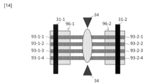
(光ファイバの被覆除去と融着接続)
電極棒34は、被覆除去と融着接続の二つの機能を有する。被覆除去の方法は図9において説明したとおりである。本実施形態では、電極棒34がガラス部93-1-1~93-1-4とガラス部93-2-1~93-2-4の水平方向から放電する。 (Optical fiber coating removal and fusion splicing)
Theelectrode rod 34 has two functions: coating removal and fusion splicing. The method for removing the coating is as explained in FIG. In this embodiment, the electrode rod 34 discharges from the horizontal direction of the glass parts 93-1-1 to 93-1-4 and the glass parts 93-2-1 to 93-2-4.
電極棒34は、被覆除去と融着接続の二つの機能を有する。被覆除去の方法は図9において説明したとおりである。本実施形態では、電極棒34がガラス部93-1-1~93-1-4とガラス部93-2-1~93-2-4の水平方向から放電する。 (Optical fiber coating removal and fusion splicing)
The
融着接続も、被覆除去と同様に、図14に示すように、水平方向から放電することで、ガラス部93-1-1~93-1-4とガラス部93-2-1~93-2-4の融着接続を行う。このとき、モータM34は、ガラス部93-1-1~93-1-4とガラス部93-2-1~93-2-4の接続位置に電極棒34を移動させる。
Similar to coating removal, fusion splicing is also performed by discharging horizontally, as shown in FIG. Perform fusion splicing in step 2-4. At this time, the motor M34 moves the electrode rod 34 to the connection position between the glass parts 93-1-1 to 93-1-4 and the glass parts 93-2-1 to 93-2-4.
ここで、本開示の装置は、被覆除去を行うために、図9(b)に示したように、テープファイバ96-1の長手方向に電極棒34を移動させるモータM34を備える。これにより、テープファイバ94-1の長手方向に並行して、電極棒34から放電することで、被覆94-1の一部をテープファイバ94-1の長手方向に除去することができる。本実施形態では、モータM34が電極棒34の後段に配置される例を示す。
Here, in order to remove the coating, the apparatus of the present disclosure includes a motor M34 that moves the electrode rod 34 in the longitudinal direction of the tape fiber 96-1, as shown in FIG. 9(b). Thereby, by discharging from the electrode rod 34 in parallel to the longitudinal direction of the tape fiber 94-1, a part of the coating 94-1 can be removed in the longitudinal direction of the tape fiber 94-1. In this embodiment, an example is shown in which the motor M34 is arranged after the electrode rod 34.
また、放電後に被覆94-1の煤を取り除くためのエアブロー35と、ガラス部93-1の状態を確認するためのカメラ36を備える。カメラ36は、被覆94-1の上面から撮影をした方が広範囲にわかるため、金属刃33と同じモータM33に固定してもよい。また、カメラ36を上部に配置することで、図13で説明したテープファイバ96-1A及び96-2の位置合わせをカメラ36で視認することができる。
It also includes an air blower 35 for removing soot from the coating 94-1 after discharge, and a camera 36 for checking the state of the glass portion 93-1. The camera 36 may be fixed to the same motor M33 as the metal blade 33, since a wider area can be seen by taking pictures from the top surface of the covering 94-1. Further, by arranging the camera 36 at the top, it is possible to visually check the alignment of the tape fibers 96-1A and 96-2 described in FIG. 13 with the camera 36.
以上説明したように、本開示は、被覆除去、切断、移設先ファイバの移動、融着接続の機能を、装置1台の中に盛り込むことができる。さらに、本開示の装置は、被覆除去、切断、移設先ファイバの移動、融着接続の動作を順に実行する制御部37を備える。これにより、本開示の装置は、テープファイバ96-1を固定部31-1に固定し、テープファイバ96-2を固定部31-2に固定した後、スイッチ1つで、光ファイバの切替接続の一連の作業を実施できるようにすることができる。
As explained above, the present disclosure can incorporate the functions of coating removal, cutting, moving the fiber to be relocated, and fusion splicing into a single device. Furthermore, the apparatus of the present disclosure includes a control unit 37 that sequentially performs the operations of removing the coating, cutting, moving the fiber to be relocated, and fusion splicing. As a result, the device of the present disclosure fixes the tape fiber 96-1 to the fixing part 31-1 and fixes the tape fiber 96-2 to the fixing part 31-2, and then switches and connects the optical fibers with a single switch. A series of tasks can be carried out.
(得られる効果)
装置1台に機能を集約したことで、スイッチを押す簡単な動作のみで、簡単に光ファイバを切り替えることである。本作業は、背景に述べたように、屋外での作業のため、暗い中、寒い中、雨の中で実施している作業であり、装置が複数台用いているため、作業者はスキルが必要である。本発明に従う方法では、装置が1台になり、さらに、スイッチ一つで装置が動作するため、作業員へ要求されるスキルレベルを低くできる(だれでも作業ができる)。日本国の人口が減少しており、どの産業でも人で不足となっているが、その課題解決にも貢献ができる。 (Effects obtained)
By consolidating functions into one device, optical fibers can be easily switched with just the simple action of pressing a switch. As mentioned in the background, this work is carried out outdoors, in the dark, in the cold, and in the rain, and because multiple devices are used, the workers are not skilled. is necessary. In the method according to the present invention, only one device is required, and the device can be operated with a single switch, so the skill level required of the worker can be lowered (anyone can perform the work). Japan's population is decreasing, and every industry is facing a shortage of people, and we can contribute to solving this problem.
21:固定台
22:押圧台
23、25:刃
24:電極棒
31-1、31-2:固定部材
32:押圧台
33:金属刃
34:電極棒
35:エアブロー
36:カメラ
37:制御部
81:OLT
82:ONU
83:IDM
84-1、84-2:光ケーブル
85:スプリッタ
91:コアガラス
92:クラッドガラス
93、93-1、93-1-1、93-1-2、93-1-3、93-1-4、93-2、93-2-1、93-2-2、93-2-3、93-2-4:ガラス部
94、94-1、94-2:被覆
95、95-1、95-2:光ファイバ
96、96-1、96-2:テープファイバ 21: Fixed base 22: Pressingbase 23, 25: Blade 24: Electrode rods 31-1, 31-2: Fixed member 32: Pressing base 33: Metal blade 34: Electrode rod 35: Air blow 36: Camera 37: Control unit 81 :OLT
82: ONU
83:IDM
84-1, 84-2: Optical cable 85: Splitter 91: Core glass 92:Clad glass 93, 93-1, 93-1-1, 93-1-2, 93-1-3, 93-1-4, 93-2, 93-2-1, 93-2-2, 93-2-3, 93-2-4: Glass portion 94, 94-1, 94-2: Covering 95, 95-1, 95-2 :Optical fiber 96, 96-1, 96-2: Tape fiber
22:押圧台
23、25:刃
24:電極棒
31-1、31-2:固定部材
32:押圧台
33:金属刃
34:電極棒
35:エアブロー
36:カメラ
37:制御部
81:OLT
82:ONU
83:IDM
84-1、84-2:光ケーブル
85:スプリッタ
91:コアガラス
92:クラッドガラス
93、93-1、93-1-1、93-1-2、93-1-3、93-1-4、93-2、93-2-1、93-2-2、93-2-3、93-2-4:ガラス部
94、94-1、94-2:被覆
95、95-1、95-2:光ファイバ
96、96-1、96-2:テープファイバ 21: Fixed base 22: Pressing
82: ONU
83:IDM
84-1, 84-2: Optical cable 85: Splitter 91: Core glass 92:
Claims (8)
- 光ファイバに備わるガラス部を融着接続する一対の電極棒を備え、
前記一対の電極棒を用いて、前記光ファイバに備わる被覆を除去することを特徴とする装置。 Equipped with a pair of electrode rods for fusion splicing the glass part of the optical fiber,
An apparatus characterized in that a coating provided on the optical fiber is removed using the pair of electrode rods. - 前記一対の電極棒を、前記光ファイバの長手方向に移動させる電極棒可動部を備える、
請求項1に記載の装置。 comprising an electrode rod movable part that moves the pair of electrode rods in the longitudinal direction of the optical fiber;
The device according to claim 1. - 前記一対の電極棒が前記被覆を溶解させ、
前記被覆の溶解によって生じた煤を除去するエアブローと、
前記一対の電極棒によって露出した前記ガラス部を撮像するカメラと、
を備える請求項1に記載の装置。 the pair of electrode rods dissolve the coating;
air blowing to remove soot produced by melting the coating;
a camera that images the glass portion exposed by the pair of electrode rods;
2. The device of claim 1, comprising: - 前記一対の電極棒が、1000℃以上の温度と、200℃以上1000℃未満の温度と、で切り替え可能である、
請求項1に記載の装置。 The pair of electrode rods can be switched between a temperature of 1000°C or more and a temperature of 200°C or more and less than 1000°C.
A device according to claim 1. - 前記ガラス部に傷をつける金属刃と、
前記ガラス部のうちの前記金属刃の配置されている側面と対向する側面で、前記ガラス部を押さえる押圧台と、
前記金属刃を前記ガラス部の表面に移動させる金属刃可動部と、
前記押圧台を前記ガラス部の表面に移動させる押圧台可動部と、
を備える請求項1に記載の装置。 a metal blade that scratches the glass portion;
a press base that presses the glass portion on a side surface of the glass portion that is opposite to the side surface where the metal blade is arranged;
a metal blade movable part that moves the metal blade to the surface of the glass part;
a press base movable part that moves the press base to the surface of the glass part;
2. The device of claim 1, comprising: - 一対の電極棒を備える装置が実行する方法であって、
前記一対の電極棒を用いて、第1の光ファイバに備わる被覆を除去し、
前記一対の電極棒を用いて、前記第1の光ファイバに備わるガラス部と第2の光ファイバに備わるガラス部とを融着接続する、
方法。 A method carried out by a device comprising a pair of electrode rods, the method comprising:
removing the coating provided on the first optical fiber using the pair of electrode rods,
fusion splicing a glass portion of the first optical fiber and a glass portion of the second optical fiber using the pair of electrode rods;
Method. - 前記第1の光ファイバの長手方向に並行して、前記一対の電極棒から放電することで、前記第1の光ファイバの被覆の一部を前記第1の光ファイバの長手方向に除去し、
前記第1の光ファイバの被覆の除去後に、エアブローで表面に残った煤を取り除き、
さらに、前記被覆が除去されることによって露出した前記第1の光ファイバのガラス部を、カメラでモニタする、
請求項6に記載の方法。 removing a part of the coating of the first optical fiber in the longitudinal direction of the first optical fiber by discharging from the pair of electrode rods in parallel with the longitudinal direction of the first optical fiber;
After removing the coating of the first optical fiber, remove the soot remaining on the surface by air blowing,
further, monitoring the glass portion of the first optical fiber exposed by the removal of the coating with a camera;
The method according to claim 6. - 前記第1の光ファイバ及び前記第2の光ファイバが、異なる位置に配置されている通信ビルから伸びる光ファイバである、
請求項6に記載の方法。 the first optical fiber and the second optical fiber are optical fibers extending from communication buildings located at different locations;
The method according to claim 6.
Priority Applications (1)
| Application Number | Priority Date | Filing Date | Title |
|---|---|---|---|
| PCT/JP2022/025258 WO2023248457A1 (en) | 2022-06-24 | 2022-06-24 | Apparatus and method for switching connection of optical fibers |
Applications Claiming Priority (1)
| Application Number | Priority Date | Filing Date | Title |
|---|---|---|---|
| PCT/JP2022/025258 WO2023248457A1 (en) | 2022-06-24 | 2022-06-24 | Apparatus and method for switching connection of optical fibers |
Publications (1)
| Publication Number | Publication Date |
|---|---|
| WO2023248457A1 true WO2023248457A1 (en) | 2023-12-28 |
Family
ID=89379333
Family Applications (1)
| Application Number | Title | Priority Date | Filing Date |
|---|---|---|---|
| PCT/JP2022/025258 WO2023248457A1 (en) | 2022-06-24 | 2022-06-24 | Apparatus and method for switching connection of optical fibers |
Country Status (1)
| Country | Link |
|---|---|
| WO (1) | WO2023248457A1 (en) |
Citations (7)
| Publication number | Priority date | Publication date | Assignee | Title |
|---|---|---|---|---|
| JPS6043615A (en) * | 1983-08-22 | 1985-03-08 | Nippon Telegr & Teleph Corp <Ntt> | Optical fiber for switching connection |
| JPH02195304A (en) * | 1989-01-23 | 1990-08-01 | Sumitomo Electric Ind Ltd | Fusion splicing method for optical fiber |
| JPH05333227A (en) * | 1992-03-30 | 1993-12-17 | Furukawa Electric Co Ltd:The | Fusion splicing method for optical fiber |
| JPH07209542A (en) * | 1994-01-12 | 1995-08-11 | Hitachi Cable Ltd | Reinforcing structure of heat resistant optical fiber juncture |
| JP2003029046A (en) * | 2001-07-11 | 2003-01-29 | Mitsubishi Electric Corp | Apparatus for removing coating of optical fiber |
| JP2003075677A (en) * | 2001-09-03 | 2003-03-12 | Sumitomo Electric Ind Ltd | Fusion splicing method for optical fiber |
| CN111273399A (en) * | 2020-03-12 | 2020-06-12 | 常熟理工学院 | Micron-sized temperature-control self-cleaning coating layer stripping mechanism |
-
2022
- 2022-06-24 WO PCT/JP2022/025258 patent/WO2023248457A1/en unknown
Patent Citations (7)
| Publication number | Priority date | Publication date | Assignee | Title |
|---|---|---|---|---|
| JPS6043615A (en) * | 1983-08-22 | 1985-03-08 | Nippon Telegr & Teleph Corp <Ntt> | Optical fiber for switching connection |
| JPH02195304A (en) * | 1989-01-23 | 1990-08-01 | Sumitomo Electric Ind Ltd | Fusion splicing method for optical fiber |
| JPH05333227A (en) * | 1992-03-30 | 1993-12-17 | Furukawa Electric Co Ltd:The | Fusion splicing method for optical fiber |
| JPH07209542A (en) * | 1994-01-12 | 1995-08-11 | Hitachi Cable Ltd | Reinforcing structure of heat resistant optical fiber juncture |
| JP2003029046A (en) * | 2001-07-11 | 2003-01-29 | Mitsubishi Electric Corp | Apparatus for removing coating of optical fiber |
| JP2003075677A (en) * | 2001-09-03 | 2003-03-12 | Sumitomo Electric Ind Ltd | Fusion splicing method for optical fiber |
| CN111273399A (en) * | 2020-03-12 | 2020-06-12 | 常熟理工学院 | Micron-sized temperature-control self-cleaning coating layer stripping mechanism |
Similar Documents
| Publication | Publication Date | Title |
|---|---|---|
| JP7294419B2 (en) | Communication equipment identification device, optical fiber connection system, communication equipment identification method, and optical fiber connection method | |
| US5408556A (en) | 1 X N splitter for single-mode fibers and method of construction | |
| JPH0439044B2 (en) | ||
| WO2023248457A1 (en) | Apparatus and method for switching connection of optical fibers | |
| EP2183625A1 (en) | Improvements relating to photonic crystal waveguides | |
| Gonda et al. | Recent progress and outlook on multicore fiber for practical use | |
| CN1510445A (en) | Fibre-optical component for light-spot size change and manufacturing method thereof | |
| JP2012073407A (en) | Optical fiber end part processing method and optical fiber end part processing device | |
| EP1203251A2 (en) | Use of a laser to fusion-splice optical components of substantially different cross-sectional areas | |
| Cui et al. | Modeling the splice loss of ultra-low loss fiber and single-mode optical fiber in high altitude area | |
| WO2022009286A1 (en) | Optical fiber and connection method therefor | |
| US11886009B2 (en) | Coating fusion spliced optical fibers and subsequent processing methods thereof | |
| US20190331868A1 (en) | Methods for coupling optical fibers to optical chips with high yield and low-loss | |
| JP4835618B2 (en) | Optical connector | |
| CN103376519A (en) | Urgent repair method for special optical cable | |
| US6827507B2 (en) | Systems and methods for reducing splice loss in optical fibers | |
| WO2023223505A1 (en) | Optical fiber changeover method and optical communication device | |
| WO2002033464A9 (en) | Low reflection optical fiber terminators | |
| WO2023223502A1 (en) | Method and device for connecting optical fibers | |
| CN218938552U (en) | High-speed communication optical fiber and optical fiber communication system | |
| GB2175410A (en) | Optical fibre fusion splicing | |
| Tiihonen | An Installation Project of an Optical Fiber Backbone Line | |
| Murase et al. | Single-mode non-strippable primary coated fiber | |
| Regio | Fusion Splices Reliability (WG1. 1 SG3) | |
| CN108802906A (en) | A kind of cable connection method based on optical cable clamp |
Legal Events
| Date | Code | Title | Description |
|---|---|---|---|
| 121 | Ep: the epo has been informed by wipo that ep was designated in this application |
Ref document number: 22948018 Country of ref document: EP Kind code of ref document: A1 |