WO2023243455A1 - 虚像表示装置 - Google Patents
虚像表示装置 Download PDFInfo
- Publication number
- WO2023243455A1 WO2023243455A1 PCT/JP2023/020773 JP2023020773W WO2023243455A1 WO 2023243455 A1 WO2023243455 A1 WO 2023243455A1 JP 2023020773 W JP2023020773 W JP 2023020773W WO 2023243455 A1 WO2023243455 A1 WO 2023243455A1
- Authority
- WO
- WIPO (PCT)
- Prior art keywords
- display
- virtual image
- display area
- abnormality
- content
- Prior art date
- Legal status (The legal status is an assumption and is not a legal conclusion. Google has not performed a legal analysis and makes no representation as to the accuracy of the status listed.)
- Ceased
Links
Images





Classifications
-
- B—PERFORMING OPERATIONS; TRANSPORTING
- B60—VEHICLES IN GENERAL
- B60K—ARRANGEMENT OR MOUNTING OF PROPULSION UNITS OR OF TRANSMISSIONS IN VEHICLES; ARRANGEMENT OR MOUNTING OF PLURAL DIVERSE PRIME-MOVERS IN VEHICLES; AUXILIARY DRIVES FOR VEHICLES; INSTRUMENTATION OR DASHBOARDS FOR VEHICLES; ARRANGEMENTS IN CONNECTION WITH COOLING, AIR INTAKE, GAS EXHAUST OR FUEL SUPPLY OF PROPULSION UNITS IN VEHICLES
- B60K35/00—Instruments specially adapted for vehicles; Arrangement of instruments in or on vehicles
-
- G—PHYSICS
- G02—OPTICS
- G02B—OPTICAL ELEMENTS, SYSTEMS OR APPARATUS
- G02B27/00—Optical systems or apparatus not provided for by any of the groups G02B1/00 - G02B26/00, G02B30/00
- G02B27/01—Head-up displays
-
- G—PHYSICS
- G09—EDUCATION; CRYPTOGRAPHY; DISPLAY; ADVERTISING; SEALS
- G09G—ARRANGEMENTS OR CIRCUITS FOR CONTROL OF INDICATING DEVICES USING STATIC MEANS TO PRESENT VARIABLE INFORMATION
- G09G5/00—Control arrangements or circuits for visual indicators common to cathode-ray tube indicators and other visual indicators
-
- G—PHYSICS
- G09—EDUCATION; CRYPTOGRAPHY; DISPLAY; ADVERTISING; SEALS
- G09G—ARRANGEMENTS OR CIRCUITS FOR CONTROL OF INDICATING DEVICES USING STATIC MEANS TO PRESENT VARIABLE INFORMATION
- G09G5/00—Control arrangements or circuits for visual indicators common to cathode-ray tube indicators and other visual indicators
- G09G5/36—Control arrangements or circuits for visual indicators common to cathode-ray tube indicators and other visual indicators characterised by the display of a graphic pattern, e.g. using an all-points-addressable [APA] memory
- G09G5/38—Control arrangements or circuits for visual indicators common to cathode-ray tube indicators and other visual indicators characterised by the display of a graphic pattern, e.g. using an all-points-addressable [APA] memory with means for controlling the display position
Definitions
- the disclosure in this specification relates to a virtual image display device that displays a virtual image.
- the present disclosure aims to provide a virtual image display device that can suppress the impact on the user due to the occurrence of an abnormality even if the display area of the virtual image is displaceable.
- a virtual image display device that is used in a vehicle and displays a virtual image superimposed on the foreground, and the position of the display area where the virtual image is displayed is set at the top and bottom of the vehicle.
- a display control unit that controls the position of the display area according to the contents of the content displayed as a virtual image; and an abnormality that detects at least fixation of the display area as an abnormality in the displacement of the display area.
- a detection section, the display control section is a virtual image display device that performs fail-safe control of contents according to the stuck position of the display area when the abnormality detection section detects that the display area is stuck.
- a head-up display (hereinafter referred to as HUD) 100 is a virtual image display device that displays a virtual image Vi.
- the HUD 100 constitutes a display system 110 together with the meter display device 30 and the like.
- the display system 110 is used in the vehicle Am, and presents various information related to the vehicle Am to the driver by linking the virtual image display by the HUD 100 and the screen display by the meter display device 30.
- the meter display device 30 is one of a plurality of display devices mounted on the vehicle Am, and presents information to the driver by displaying an image on a display screen.
- the meter display device 30 has a configuration corresponding to a combination meter, and is housed in the instrument panel 9 with the display screen facing the driver's seat.
- the meter display device 30 includes a meter display 31 and a meter ECU 32.
- the meter ECU 32 is an electronic control device that controls the user interface function of the vehicle Am.
- the meter ECU 32 integrally controls displays by display devices such as the meter display 31, the HUD 100, and the center display.
- the meter ECU 32 mainly includes a computer including a processing section, RAM, storage, an input/output interface, a bus connecting these, and the like.
- the meter ECU 32 generates video data to be provided to the meter display 31 based on various information output to the communication bus.
- the meter ECU 32 cooperates with a head-up ECU 70, which will be described later, and executes arithmetic processing for displaying a virtual image.
- the meter ECU 32 generates image data used to display the virtual image Vi, and sequentially outputs the generated image data to the HUD 100.
- the PGU 61 has an LCD (Liquid Crystal Display) panel and a backlight.
- the PGU 61 is fixed to the housing of the HUD 100 with the display surface of the LCD panel facing the magnifying optical system 62 (a plane mirror described later).
- the PGU 61 displays each frame image of the video data on the display surface of the LCD panel, and directs the display light Lvi, which is formed as a virtual image Vi, toward the enlarging optical system 62 by transmitting and illuminating the display surface with a backlight. eject.
- the relative positional relationship between the normal position VP1 and the upper position VP2 may be changed as appropriate.
- the lower edge of the upper position VP2 may be in contact with the upper edge of the normal position VP1, or may be slightly apart from the upper edge of the normal position VP1.
- the display area VA at the upper position VP2 and the display area VA at the normal position VP1 may partially overlap.
- the information acquisition unit 71 is connected to the communication bus and the meter ECU 32.
- the information acquisition unit 71 acquires route information provided by the navigation ECU 21, and target information and control status information around the own vehicle provided by the driving support ECU 22 from the communication bus.
- Image data for displaying a virtual image generated by the meter ECU 32 is sequentially input to the information acquisition unit 71.
- the information acquisition section 71 is electrically connected to the operation section 68.
- the operation unit 68 is a switch that allows the driver to adjust the position of the display area VA and to turn on and off the display of the virtual image Vi.
- a dedicated switch provided on the instrument panel 9, a steering switch provided on the steering wheel, a center display with a touch panel function, an audio input device that detects the driver's utterances, etc. can be used as the operation unit 68. .
- the information acquisition unit 71 acquires information input to the operation unit 68 when the operation unit 68 is operated by a driver or the like.
- the input information is provided from the information acquisition unit 71 to the display control unit 72, and the position adjustment of the display area VA and the on/off switching of the virtual image display are performed according to the driver's operation.
- Adjusting the position of the display area VA corresponds to user calibration for adapting the position of the display area VA to each driver.
- User calibration is performed when each driver uses HUD 100 (vehicle Am) for the first time.
- the driver operates the operation unit 68 to set the eye point EP to the normal position so that the virtual image Vi will not be cut off even if the eye point EP is slightly moved in the up-down direction US, the left-right direction Yo, and the front-back direction ZG. Adjust VP1 and upper position VP2.
- the setting value of the position of the display area VA associated with each driver is stored in the storage 53.
- the display control unit 72 is a control unit that integrally controls the PGU 61 and the actuator 63a.
- the display control unit 72 generates video data and control signals to be output to the PGU 61, and drive signals to be output to the actuator 63a.
- the display control unit 72 selects the content CT to be displayed as the virtual image Vi, and controls the position of the display area VA according to the contents of the content CT to be displayed.
- the display control unit 72 Based on the information acquired by the information acquisition unit 71, the display control unit 72 refers to a preset data table and selects the content CT to be displayed as a virtual image and the position of the display area VA.
- the display control unit 72 extracts material data of an image used for generating video data from the RAM 52 or the storage 53 based on the selection result of the content CT.
- the display control unit 72 appropriately combines the image data generated from the material data and the image data provided by the meter ECU 32 to generate each frame image of the video data.
- the display control unit 72 sequentially outputs video data consisting of a large number of consecutive frame images to the PGU 61.
- the display control unit 72 When determining to move the display area VA, the display control unit 72 switches the contents of the content CT to be displayed as a virtual image in relation to the start or end of driving of the actuator 63a. As an example, when moving the display area VA from the normal position VP1 to the upper position VP2, the display control unit 72 switches the content CT to be displayed as a virtual image immediately before starting the movement of the display area VA. On the other hand, when moving the display area VA from the upper position VP2 to the normal position VP1, the display control unit 72 switches the content CT to be displayed as a virtual image immediately after completing the movement of the display area VA. Further, in the above-described user calibration, the display control unit 72 displays, for example, virtual images Vi indicating the positions of the four corners, four sides, and the center of the display area VA as content CT for position adjustment.
- the abnormality detection unit 73 is connected to the PGU 61, the actuator 63a, and the position sensor 64, and detects various abnormalities that occur in the HUD 100, such as abnormalities in the displacement of the display area VA and abnormalities in the image. Specifically, the abnormality detection unit 73 is capable of detecting a circuit abnormality of the head-up ECU 70, a software abnormality of the virtual image display program, etc. in addition to an abnormality of the PGU 61, an abnormality of the actuator 63a, and a malfunction of the gear unit. The abnormality detection unit 73 determines that an abnormality has occurred when the same abnormality has been detected a plurality of times (for example, about three times).
- abnormality detection information information indicating the abnormality detection
- abnormality type information information indicating the type of detected abnormality
- the display control unit 72 performs fail-safe control so as not to impede normal driving by the driver.
- the display control unit 72 starts failsafe transition processing (see FIG. 5) based on the acquisition of the abnormality detection information from the abnormality detection unit 73.
- the display control unit 72 acquires abnormality type information attached to the abnormality detection information (S11), and grasps the type of abnormality, which will be described later, based on the abnormality type information (S12).
- the display control unit 72 selects an abnormality response that is linked in advance to the detected abnormality type (S13), and starts the fail-safe control that has been decided to be implemented by shifting to the fail-safe mode (S14). Details of the failsafe control for each abnormality type performed by the display control unit 72 will be described below based on FIGS. 6 to 12 and with reference to FIGS. 1 and 2.
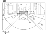
- the abnormality detection unit 73 detects, as an abnormality in the displacement of the display area VA, an abnormality in which the display area VA rises too much from the normal position (see the lower reference line RBL), such as the normal position VP1H and the upper position VP2H shown in FIG. do.
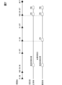
- the abnormality detection unit 73 refers to the output signal of the position sensor 64, compares the current position and the desired position, and detects a state in which the difference (see arrow) exceeds the threshold multiple times (for example, about 3 times). If it is detected continuously, it is determined that there is an abnormality of excessive rise (see Figure 7 Abnormality Occurrence).
- the phenomenon in which the display area VA becomes too high is caused by the tilt angle of the concave mirror 62a being deviated from its normal position due to vibrations or the like due to repeated displacement in the vertical direction US while the vehicle is running. If the display area VA rises too much, the content CT displayed as a virtual image at the upper position VP2H may be located in the central visual field CVF and obstruct the driver's forward view, thereby interfering with normal driving.
- the abnormality detection unit 73 detects that the display area VA has risen too much, it provides the display control unit 72 with abnormality type information indicating that the display area VA has risen too much in addition to the abnormality detection information.
- the display control unit 72 continues to display the virtual image Vi even if the abnormality detection unit 73 detects that the display area VA has risen too much. When the abnormality detection unit 73 detects that the display area VA has risen too much, the display control unit 72 may continue the state in which the display area VA can be displaced, or may restrict (prohibit) the displacement of the display area VA. ) may be done.
- the display control unit 72 performs return processing of the displacement mechanism 63 at a predetermined timing as fail-safe control.
- the predetermined timing is, for example, the next time the HUD 100 is activated, specifically the timing when the ignition state of the vehicle Am is switched from the off state to the on state (see IG ON in FIG. 7). Note that the ON state of the ignition of the vehicle Am indicates a state in which the vehicle Am can travel by shifting to the drive range.
- the display control unit 72 controls the drive of the actuator 63a while referring to the output signal of the position sensor 64, and resets the reference position (zero point) of the tilt angle of the concave mirror 62a (see ZPD in FIG. 7). ). After resetting the reference position, the display control unit 72 can return the display area VA to the normal position again by reading the value set in the user calibration. Note that the display control unit 72 resets the reference position based on the fact that "enable" of the HUD 100 has been switched to the OFF state, regardless of whether an abnormality has occurred, in other words, in both normal and abnormal conditions. (See Figure 7 EN OFF). The display control unit 72 can return the display area VA to the normal position at a timing earlier than in normal times by performing reset of the reference position based on switching on of the ignition power supply as a return process only in abnormal situations.
- the display control unit 72 may continue both the displacement of the display area VA and the display of the virtual image Vi after it is determined that the display area VA has risen too much and an abnormality has occurred. In this case, the display control unit 72 maintains a state in which the position of the display area VA can be changed by operation input to the operation unit 68 until the HUD 100 is turned off. That is, as fail-safe control, the display control unit 72 puts the position of the display area VA in a state where it can be changed, and then performs the return process at a predetermined timing. Even if the driver adjusts the position to return the display area VA that has risen too much, the display control unit 72 returns the display area VA to the initial value set by the initial user calibration in the above-mentioned restoration process. Restore position.
- the driver lowers the upper position VP2H and the normal position VP1H, which have risen too high, to appropriate positions by inputting an operation to the operation unit 68 during a period when the vehicle Am is temporarily stopped. Adjustments can be made.
- the vertical movement of the display area VA within the normal movable range is resumed without causing the virtual image Vi to be cut off. Note that when the return process is performed, the result of adjusting the view angle position that was performed after the excessive rise was detected may be discarded.
- the abnormality detection unit 73 detects fixation of the display area VA as an abnormality in the displacement of the display area VA.
- the abnormality detection unit 73 determines that sticking has occurred when the tilt angle of the concave mirror 62a, that is, the output signal of the position sensor 64 remains unchanged despite driving the actuator 63a.
- the display area VA may become stuck due to malfunction of the actuator 63a, malfunction of the gear unit, malfunction of the control circuit or software, or the like.
- the abnormality detection unit 73 refers to the output signal of the position sensor 64 and further specifies the position where the sticking has occurred.
- the abnormality detection unit 73 provides the display control unit 72 with abnormality type information indicating that the sticking has occurred and the location of the occurrence, in addition to the abnormality detection information.
- the first content CT1 that should be displayed at the normal position VP1 is displayed inside or near the central visual field CVF.
- the first content CT1 displayed at the normal position VP1 is often a fast-moving display or a display with a large amount of information. Therefore, if the first content CT1 is displayed within the display area VA at the upper position VP2 without lowering the display area VA, the driver's forward view may be obstructed and normal driving may be hindered.
- the display control unit 72 starts troubleshooting using fail-safe control earlier than when the display area VA is stuck at the normal position VP1. Specifically, when the display area VA is stuck at the upper position VP2, the display control unit 72 determines whether the content CT being displayed obstructs the driver's field of view. The display control unit 72 estimates whether a phenomenon such as flickering occurs or not based on the display size of the content CT being displayed, the speed of display change, the display position within the viewing angle, etc. The display control unit 72 may estimate that a phenomenon such as flickering occurs when displaying a predefined specific content CT, or may grasp the display state of the content CT being displayed and prevent flickering. It is also possible to estimate whether or not such phenomena are accompanied. If it is estimated that a phenomenon such as flickering is involved, the display control unit 72 determines that the content CT being displayed obstructs the view.
- the display control unit 72 determines that the content CT being displayed obstructs the view, the display control unit 72 does not perform the above-mentioned return process, continues displaying the second content CT2 (see FIG. 4), and continues displaying the first content CT1. Abort. As described above, flickering of the virtual image Vi caused by, for example, a change in the number of the speedometer CTv is prevented.
- the display control unit 72 stops displaying the virtual image Vi such as the first content CT1
- the display control unit 72 starts the display at a predetermined timing such as the next time the ignition of the vehicle Am changes from the off state to the on state (see IG ON in FIG. 7). , executes the return process of the displacement mechanism 63.
- the display control unit 72 resets the reference position as a return process based on the ON switching of the ignition state only when the abnormality occurs (see FIG. 7 ZPD at the time of abnormality). .
- the display control unit 72 resumes displaying the first content CT1 when the fixation is resolved by the recovery process.
- the display control unit 72 continues the state where the display of the first content CT1 is stopped.
- the display control unit 72 determines that the content CT being displayed does not obstruct the view, it immediately starts the above-mentioned return process as fail-safe control.
- the display control unit 72 resumes displaying the virtual image Vi when the fixation is resolved by the recovery process.
- the display control unit 72 continues displaying the second content CT2 and stops displaying the first content CT1.
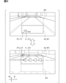
- ⁇ Abnormality type 3 Display area VA is stuck at intermediate position> As shown in FIG. 9, even if the display area VA does not fully transition and is stuck between the normal position VP1 and the upper position VP2 (hereinafter referred to as the intermediate position VPM), the speedometer CTv, etc. Content CT1 is displayed. In this case, as in the case where the vehicle is stuck at the upper position VP2, the driver's forward view may be obstructed and normal driving may be hindered.
- the display control unit 72 When the abnormality detection unit 73 detects sticking at the intermediate position VPM, the display control unit 72 performs the same fail-safe control as when sticking at the upper position VP2 is detected. Specifically, the display control unit 72 determines whether the content CT being displayed obstructs the driver's view, and if it is determined that the content CT being displayed does not obstruct the driver's view, the display control unit 72 displays the second content CT2 (see FIG. 4). ) continues to be displayed, and stops displaying the first content CT1. After stopping the display of the first content CT1, the display control unit 72 performs the above-mentioned return at a predetermined timing such as the next time the ignition of the vehicle Am is turned on from the off state (see IG ON in FIG. 7). Perform processing.
- a predetermined timing such as the next time the ignition of the vehicle Am is turned on from the off state (see IG ON in FIG. 7). Perform processing.
- ⁇ Abnormality type 5 Display area VA is stuck at normal position VP1>
- the abnormality detection unit 73 detects fixation of the display area VA at the normal position VP1 as shown in FIG. 11 as an abnormality in the displacement of the display area VA.
- the second content CT2 that should be displayed at the upper position VP2 is displayed at the normal position VP1.
- the second content CT2 is only displayed lower than in normal times, and is unlikely to become a display object that obstructs the driver's forward view. Therefore, the display control unit 72 continues displaying the virtual image Vi when the display area VA is fixed at the normal position VP1.
- the display control unit 72 performs the above-described recovery process at a predetermined timing (see IG ON in FIG. 7), such as the next time the ignition of the vehicle Am is turned on from the off state. Even if a type 5 sticking abnormality occurs, the display control unit 72 resets the reference position as a return process based on the ON switching of the ignition state only when the abnormality occurs (see FIG. 7 ZPD at the time of abnormality). . Even if the fixation is not resolved by the recovery process, the display control unit 72 continues to display the virtual image Vi.
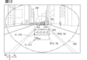
- the phenomenon in which the display area VA falls too low is caused by the tilt angle of the concave mirror 62a deviating from the normal position due to repeated displacement of the display area VA during driving, similar to the above-mentioned abnormality in which the display area VA falls too much.
- the display control unit 72 continues to display the virtual image Vi even if the abnormality detection unit 73 detects that the display area VA has fallen too much.
- the display control unit 72 may continue the state in which the display area VA can be displaced, or may restrict (prohibit) the displacement of the display area VA. ) may be done.
- the display control unit 72 performs a return process at a predetermined timing (see FIG.
- the display control unit 72 resets the reference position as a return process based on the ON switching of the ignition state only when the abnormality occurs (see FIG. 7 ZPD at the time of abnormality) ).
- the abnormality detection unit 73 detects an abnormality in which the display area VA continues to shake (continue to move) in the vertical direction US without being fixed at a specific position, as an abnormality in the displacement of the display area VA. For example, if an abnormality occurs in the actuator 63a, the drive circuit, the gear unit, or the like, a phenomenon occurs in which the display area VA is small and continues to move in the vertical direction US, or in other words, a phenomenon in which the position of the display area VA becomes unstable occurs.
- the abnormality detection unit 73 refers to the output signal of the position sensor 64 and determines that the display area VA continues to swing up and down when a continuous change exceeding a threshold value is observed in the position of the display area VA.
- the display control unit 72 continues to display the virtual image Vi even if the abnormality detection unit 73 detects a timing shift. In this case, although the driver may feel uncomfortable when changing the position of the display area VA, it is unlikely that the content CT will interfere with the forward field of view. Therefore, priority may be given to ensuring the convenience of the driver by continuing to display the virtual image Vi.
- ⁇ Abnormality type 9 Occurrence of abnormal noise and vibration due to displacement>
- the HUD 100 is provided with an operation unit 68 that can switch the display on and off. If the driver feels that the noise and vibrations are bothersome, he or she can input an operation to turn off the display into the operation unit 68.
- the display control unit 72 stops displaying the virtual image Vi based on input information obtained from the operation unit 68.
- the abnormality detection unit 73 further detects an abnormality in the PGU 61 that emits the display light Lvi. Specifically, the abnormality detection unit 73 detects, as an abnormality of the PGU 61, an abnormality in which light from the backlight is directly emitted (hereinafter referred to as a white image abnormality).
- the white screen abnormality occurs due to an abnormality in the LCD panel, drive circuit, or the like. When a white screen abnormality occurs, the driver is forced to look away from the road ahead, making it impossible to continue driving normally.
- the display control unit 72 immediately stops displaying the virtual image Vi as fail-safe control without performing a recovery process. This avoids a situation where normal driving is hindered due to the glare of the white screen making it difficult to see ahead.
- the display of the virtual image Vi is stopped, and in a scene where the virtual image Vi is not likely to obstruct the driver's field of view, the display of the virtual image Vi is allowed to continue. Therefore, even if an abnormality occurs, the influence on the driver can be minimized.
- the position of the display area VA is switched between a plurality of positions including at least the normal position VP1 and the upper position VP2 above the normal position VP1.
- abnormality response using failsafe control is started earlier than when the display area VA is stuck at the normal position VP1.
- the display area VA is fixed at the upper position VP2, there is a possibility that the content CT in a troublesome manner will be displayed inside or near the central visual field CVF.
- an abnormality response to the sticking at the upper position VP2 is started early, even if the virtual image Vi obstructs the driver's field of vision, it can be quickly resolved.
- the display area VA when the display area VA is fixed at the upper position VP2, it is determined whether or not the content CT being displayed obstructs the driver's view. If the content CT being displayed obstructs the view, the display of the second content CT2 linked to the upper position VP2 is continued, while the display of the first content CT1 linked to the normal position VP1 is stopped. According to the above, a situation in which the first content CT1 whose display changes rapidly is displayed in the display area VA at the upper position VP2 overlapping the central visual field CVF and obstructs the driver's field of view is less likely to occur. Furthermore, since the content CT associated with the upper position VP2 continues to be displayed, the driver's convenience is less likely to be impaired.
- the display area VA when the display area VA is fixed at the normal position VP1, the display of the virtual image Vi is continued. Then, the recovery process is performed as fail-safe control at a predetermined timing. Even if the second content CT2, which is supposed to be displayed at the upper position VP2, is displayed at the fixed normal position VP1, the driver's field of view is not easily obstructed. Furthermore, since the return process is executed at a predetermined timing, the display area VA can be prevented from being stuck. As described above, by performing the process to continue displaying the virtual image Vi, the influence on the driver due to the occurrence of sticking can be suppressed to a minimum.
- the display area VA when the display area VA is fixed at an intermediate position VPM between the normal position VP1 and the upper position VP2, it is determined whether or not the content CT being displayed obstructs the driver's view. If the content CT being displayed obstructs the view, the display of the second content CT2 linked to the upper position VP2 is continued, while the display of the first content CT1 linked to the normal position VP1 is stopped. According to the above, a situation in which the first content CT1 whose display changes rapidly is displayed in the vicinity of the central visual field CVF and obstructs the driver's field of view is less likely to occur. In addition, if the content CT being displayed does not obstruct the view, the restoration process is immediately executed, making it possible to restart the virtual image display with only a temporary interruption. As a result, the driver's convenience is less likely to be impaired.
- the present embodiment as an abnormality in the displacement of the display area VA, unsmooth displacement is detected. If unsmoothness is detected, the display of the virtual image Vi is continued. In this way, even if the displacement is uneven, each content CT can be displayed at an appropriate display position, so that the driver's forward view is not easily obstructed. Furthermore, by performing the recovery process at a predetermined timing and eliminating the unsmoothness, the impact on the driver due to the occurrence of an abnormality can be suppressed.
- the display control unit 72 continues to display the virtual image Vi while allowing the driver to adjust the position of the display area VA, and The return process of the displacement mechanism 63 is performed as fail-safe control at the appropriate timing. Therefore, the driver can adjust the position of the display area VA that is too high downward, for example when the vehicle is stopped, to return it to an appropriate position. As a result, the influence on the driver due to the abnormal occurrence of excessive rise can be further suppressed.
- an excessive drop in the display area VA is detected as an abnormality in the displacement of the display area VA. If it is detected that the display area VA has fallen too much, the virtual image Vi continues to be displayed, and a return process is performed at a predetermined timing. By resetting the position of the display area VA in this manner, the movable range of the display area VA can return to the normal range. As a result, even if an abnormality of excessive drop occurs, the influence on the driver can be suppressed to a minimum.
- the display control unit 72 continues to display the virtual image Vi while allowing the driver to adjust the position of the display area VA, and The return process of the displacement mechanism 63 is performed as fail-safe control at the appropriate timing. Therefore, the driver can adjust the position of the display area VA that has fallen too far downward, for example when the vehicle is stopped, to return it to an appropriate position. As a result, it becomes possible to further suppress the influence on the driver due to the abnormal occurrence of excessively low pressure.
- an abnormality in which the timing of switching the content CT and the timing of displacing the display area VA is detected as an abnormality in the displacement of the display area VA. Even if a timing shift is detected, the virtual image Vi continues to be displayed. In this way, when the image and the operation of the actuator 63a do not match, it may give the driver a sense of discomfort when switching the display area VA, but it is unlikely to interfere with the forward field of view. Therefore, by taking measures against the abnormality to continue displaying the virtual image Vi, even if an abnormality that causes a timing shift occurs, it is possible to suppress the influence on the driver.
- the display of the virtual image Vi is stopped based on input information to the operation unit 68 that switches the display of the virtual image Vi on and off. Therefore, when abnormal noise and vibration occur due to movement of the display area VA, the driver who feels uncomfortable can stop displaying the virtual image Vi at his/her own discretion. Therefore, by preparing the operation section 68, even if an abnormality that cannot be detected by the abnormality detection section 73 occurs, the influence on the driver can be suppressed.
- an abnormality in the PGU 61 that emits the display light Lvi that is formed as the virtual image Vi is detected. Then, when an abnormality in the PGU 61 is detected, display of the virtual image Vi is stopped. When a white image abnormality occurs due to malfunction of the PGU 61, the driver is forced to look away from the front. Therefore, by immediately stopping the display of the virtual image Vi without performing the recovery process, the period during which the driver's normal driving is inhibited is shortened. As a result, the influence of abnormalities in the PGU 61 on the driver can be minimized.
- the normal position VP1 corresponds to the "first position”
- the upper position VP2 corresponds to the "second position”
- the PGU61 corresponds to the "display unit”
- the information acquisition unit 71 corresponds to the "input position”.
- the HUD 100 corresponds to a "virtual image display device”.
- the fail-safe control in the case where type 1 abnormality (display area VA rises too much) in the above embodiment may be changed as appropriate. Specifically, in Modification 1 of the above embodiment, when it is detected that the display area VA has risen too much, the display control unit 72 stops displaying the virtual image Vi altogether. Further, the display control unit 72 of the second modification of the embodiment above stops the function of displacing the display area VA, and fixes the position of the display area VA at the normal position VP1. The display control unit 72 displays the second content CT2 at the normal position VP1 in addition to the first content CT1.
- the display control unit 72 of the third modification of the embodiment above automatically adjusts the upper position VP2 based on the detection of an abnormality in which the display area VA is too high. In other words, the display control unit 72 reduces the amount of upward displacement from the normal position VP1 and sets the upper position VP2 at a lower position. Further, the display control unit 72 of the fourth modification of the embodiment described above immediately executes the recovery process based on the detection of an abnormality in which the display area VA is too high.
- the fail-safe control in the case where an abnormality of type 2 or 3 (sticking at the upper position VP2 or intermediate position VPM) occurs in the above embodiment may be changed as appropriate. Specifically, in Modification 9 of the above embodiment, in order to avoid obstruction of the view by the content CT, the display control unit 72 immediately stops displaying the virtual image Vi without performing the return process. Then, the display control unit 72 executes the return process at the next startup.
- the determination as to whether the content CT being displayed obstructs the driver's view is omitted.
- the display control unit 72 of Modification 10 continues displaying the second content CT2 and stops displaying the first content CT1 as fail-safe control.
- the display control unit 72 of Modification 11 immediately performs a recovery process as fail-safe control when the display area VA is stuck at the upper position VP2 or the intermediate position VPM.
- the failsafe control in the case where type 10 abnormality (white screen) occurs in the above embodiment may be changed as appropriate. Specifically, in Modification 20 of the above embodiment, even if the abnormality detection unit 73 detects an abnormality in the PGU 61, the display control unit 72 continues to display the virtual image Vi. When a type 10 abnormality occurs, the driver is forced to look away from the road ahead, which impedes normal driving. However, if the structure is such that type 10 abnormality is extremely unlikely to occur, the display control unit 72 may be designed to continue displaying the virtual image Vi.
- the displacement mechanism 63 of Modification 21 of the above embodiment can displace the display area VA not only in the vertical direction US but also in the horizontal direction Yo. Furthermore, the displacement mechanism 63 may position the display area VA at a position different from the normal position VP1 and the upper position VP2. Further, the displacement mechanism 63 may displace the entire optical unit including the PGU 61 and the magnifying optical system 62 with respect to the housing of the HUD 100. Furthermore, the displacement mechanism 63 may displace the housing of the HUD 100 with respect to the vehicle Am.
- the functions provided by the head-up ECU 70 and meter ECU 32 in the above embodiments can also be provided by software and hardware that executes it, only software, only hardware, or a complex combination thereof. . Furthermore, if these functions are provided by electronic circuits as hardware, each function can also be provided by digital circuits, including multiple logic circuits, or by analog circuits.
- the vehicle equipped with the above display system is not limited to a general private passenger car, but may also be a rental car, a manned taxi vehicle, a ride-sharing vehicle, a freight vehicle, a bus, etc. Furthermore, the vehicle equipped with the display system may be a right-hand drive vehicle or a left-hand drive vehicle. Furthermore, the traffic environment in which the vehicle travels may be a traffic environment that assumes left-hand traffic or may be a traffic environment that assumes right-hand traffic.
- the display control according to the present disclosure may be appropriately optimized according to the road traffic laws of each country and region, the position of the steering wheel of the vehicle, and the like.
- the virtual image display device according to technical concept 2, wherein the display control unit performs return processing of the displacement mechanism as the fail-safe control when the display area is fixed at the second position.
- the display control section includes: If the display area is fixed at the second position, determining whether the content being displayed obstructs the driver's view; If the content being displayed obstructs the view, continuing to display the second content (CT2) linked to the second position and stopping displaying the first content (CT1) linked to the first position, The virtual image display device according to technical idea 2, wherein when the content being displayed does not obstruct the view, a return process of the displacement mechanism is performed as the fail-safe control.
- the display control section includes: If the display area is fixed between the first position and the second position, determining whether the content being displayed obstructs the driver's view; If the content being displayed obstructs the view, continuing to display the second content (CT2) linked to the second position and stopping displaying the first content (CT1) linked to the first position,
- CT2 the second content
- CT1 the first content
- the abnormality detection unit further detects unsmooth displacement as an abnormality in the displacement of the display area, The display control unit continues displaying the virtual image when the abnormality detection unit detects the irregularity, and performs a return process of the displacement mechanism at a predetermined timing as the fail-safe control.
- the virtual image display device according to any one of Ideas 2 to 8.
- the abnormality detection unit further detects an excessive rise in the display area as an abnormality in the displacement of the display area, According to any of technical ideas 1 to 9, the display control unit performs a return process of the displacement mechanism as the fail-safe control at a predetermined timing when the abnormality detection unit detects that the display area has risen too much.
- the virtual image display device according to any one of the items.
- the abnormality detection unit further detects an excessive drop in the display area as an abnormality in the displacement of the display area, According to any of technical ideas 1 to 10, the display control unit performs a return process of the displacement mechanism as the fail-safe control at a predetermined timing when the abnormality detection unit detects that the display area has fallen too much.
- the virtual image display device according to any one of the items.
- the abnormality detection unit further detects an abnormality in which the display area continues to shake in the vertical direction as an abnormality in the displacement of the display area
- the display control section includes: If the abnormality detection unit detects that the display area continues to shake, determining whether the content being displayed obstructs the driver's view; If the content being displayed obstructs the view, stopping the display of the virtual image as the fail-safe control;
- the virtual image display device according to any one of technical ideas 1 to 11, wherein, when the content being displayed does not obstruct the view, a return process of the displacement mechanism is performed as the fail-safe control.
- the abnormality detection unit further detects an abnormality in which the display area continues to shake in the vertical direction as an abnormality in the displacement of the display area, The virtual image display device according to any one of technical ideas 1 to 11, wherein the display control unit continues displaying the virtual image even if the abnormality detection unit detects continued shaking of the display area.
- the abnormality detection unit further detects, as an abnormality in the displacement of the display area, an abnormality in which the timing of switching the content and the timing of displacing the display area are different from each other, The virtual image display device according to any one of technical ideas 1 to 13, wherein the display control unit continues displaying the virtual image even if the abnormality detection unit detects a timing shift.
- (Technical Thought 15) further comprising an input grasping section (71) that acquires input information to the operation section (68) for switching on and off the display of the virtual image,
- the virtual image display device according to any one of technical ideas 1 to 14, wherein the display control unit stops displaying the virtual image based on the input information.
- the abnormality detection unit further detects an abnormality in the display unit (61) that emits the display light (Lvi) that is formed as the virtual image, The virtual image according to any one of technical ideas 1 to 15, wherein the display control unit stops displaying the virtual image as the fail-safe control when the abnormality detection unit detects an abnormality in the display unit. Display device.
- the abnormality detection unit further detects an abnormality in the display unit (61) that emits the display light (Lvi) that is formed as the virtual image,
- the virtual image display device according to any one of technical ideas 1 to 15, wherein the display control section continues displaying the virtual image even if the abnormality detection section detects an abnormality in the display unit.
Landscapes
- Engineering & Computer Science (AREA)
- Physics & Mathematics (AREA)
- General Physics & Mathematics (AREA)
- Computer Hardware Design (AREA)
- Theoretical Computer Science (AREA)
- Chemical & Material Sciences (AREA)
- Combustion & Propulsion (AREA)
- Transportation (AREA)
- Mechanical Engineering (AREA)
- Optics & Photonics (AREA)
- Instrument Panels (AREA)
Abstract
Description
異常検知部73は、表示域VAの変位の異常として、図6に示す通常位置VP1H及び上方位置VP2Hのように、正常な位置(下基準線RBL参照)から表示域VAが上がり過ぎる異常を検知する。異常検知部73は、ポジションセンサ64の出力信号を参照し、現在位置とあるべき位置との比較を行い、これらの差分(矢印参照)が閾値を超えた状態を複数回(例えば3回程度)継続して検知した場合に、上がり過ぎの異常と判定する(図7 異常発生を参照)。表示域VAが上がり過ぎる現象は、走行中における上下方向USの変位の繰り返しにより、凹面鏡62aのチルト角が振動等によって正規の位置からずれることで引き起こされる。表示域VAが上がり過ぎた場合、上方位置VP2Hに虚像表示されるコンテンツCTは、中心視野CVFに位置してドライバの前方視界を遮ることで、正常な運転を阻害する可能性がある。異常検知部73は、表示域VAの上がり過ぎを検知した場合、異常検知情報に加えて、表示域VAが上がり過ぎていることを示す異常種別情報を表示制御部72に提供する。
異常検知部73は、表示域VAの変位の異常として、表示域VAの固着を検知する。異常検知部73は、アクチュエータ63aを駆動しているにも関わらず、凹面鏡62aのチルト角、即ち、ポジションセンサ64の出力信号が変化しない状態が継続した場合に、固着が発生したと判定する。表示域VAの固着は、アクチュエータ63aの動作不良、ギヤユニットの不具合、制御回路又はソフトウェアの不具合等によって生じ得る。異常検知部73は、表示域VAの固着を検知した場合、ポジションセンサ64の出力信号を参照し、固着が発生した位置をさらに特定する。異常検知部73は、表示域VAの固着を検知した場合、異常検知情報に加えて、固着が発生したこと及びその発生位置を示す異常種別情報を表示制御部72に提供する。
図9に示すように、表示域VAが遷移しきらず、通常位置VP1及び上方位置VP2の間(以下、中間位置VPM)で固着した場合も、中心視野CVFの近傍にスピードメータCTv等の第1コンテンツCT1が表示されてしまう。この場合、上方位置VP2で固着した場合と同様に、ドライバの前方視界が遮られ、正常な運転を阻害する可能性がある。
異常検知部73は、表示域VAの変位の異常として、図10に示すような変位の不円滑を検知する。正常時において、通常位置VP1及び上方位置VP2の間での表示域VAの移動は、概ね一定の速度で実施される(図10 破線参照)。対して、アクチュエータ63a、駆動回路又はギヤユニット等に何らかの異常が生じた場合、表示域VAの移動速度は変動する(図10 実線参照)。異常検知部73は、ポジションセンサ64の出力信号を参照し、移動速度の変動が閾値を超えている場合、変位の不円滑が発生していると判定する。
異常検知部73は、表示域VAの変位の異常として、図11に示すような通常位置VP1での表示域VAの固着を検知する。通常位置VP1にて表示域VAが固着した場合、上方位置VP2に表示されるべき第2コンテンツCT2が通常位置VP1に表示される。この場合、第2コンテンツCT2は、正常時よりも下方に表示されるだけであり、ドライバの前方視界を妨げる表示物とはなり難い。故に、表示制御部72は、通常位置VP1で表示域VAが固着した場合、虚像Viの表示を継続する。表示制御部72は、フェールセーフ制御として、車両Amのイグニッションがオフ状態からオン状態になる次回起動時等の所定のタイミング(図7 IG ON参照)にて、上述の復帰処理を実施する。タイプ5の固着異常が発生した場合でも、表示制御部72は、異常発生時のみ、イグニッション状態のオン切り替えに基づき、復帰処理としての基準位置のリセットを実施する(図7 異常時のZPD参照)。復帰処理によって固着が解消しないでも、表示制御部72は、虚像Viの表示を継続する。
異常検知部73は、表示域VAの変位の異常として、図12に示す通常位置VP1L及び上方位置VP2Lのように、正常な位置(上基準線RTL参照)から表示域VAが下がり過ぎる異常を検知する。異常検知部73は、ポジションセンサ64の出力信号を参照し、現在位置とあるべき位置との比較を行い、これらの差分(矢印参照)が閾値を超えた場合に、下がり過ぎの異常と判定する。表示域VAが下がり過ぎる現象は、上述の上がり過ぎの異常と同様に、走行中における表示域VAの変位の繰り返しで、凹面鏡62aのチルト角が正規の位置からずれることで引き起こされる。
異常検知部73は、表示域VAの変位の異常として、表示域VAが特定位置で固定されずに上下方向USに揺れ続ける(動き続ける)異常を検知する。例えば、アクチュエータ63a、駆動回路又はギヤユニット等に異常が生じた場合、表示域VAが小さく上下方向USに動き続ける現象、言い替えれば、表示域VAの位置が安定しない現象が発生する。異常検知部73は、ポジションセンサ64の出力信号を参照し、表示域VAの位置について、閾値を超える継続的な変動を観測した場合、表示域VAが上下に揺れ続けていると判定する。
異常検知部73は、表示域VAの変位の異常として、コンテンツCTを切り替えるタイミングと表示域VAを変位させるタイミングとがずれる異常を検知する。異常検知部73は、表示制御部72から取得する表示制御情報に基づき、コンテンツCT(映像)の切り替えタイミングを把握する。さらに、異常検知部73は、ポジションセンサ64の出力信号を参照し、画角移動の開始タイミングを把握する。異常検知部73は、把握した各タイミングに基づき、アクチュエータ63aの動作が規定のタイミングより遅い、及び映像の切り替わりが規定のタイミングより遅い等の事象の発生を検知する。
表示域VAの変位の異常として、表示域VAの位置の上下に伴う異音又は振動の発生が想定される。こうした異常は、異常検知部73による検知が困難となる。そのため、HUD100には、表示のオン及びオフを切り替え可能な操作部68が設けられている。異音及び振動が煩わしいと感じたドライバは、表示をオフにする操作を操作部68に入力できる。表示制御部72は、操作部68から取得する入力情報に基づき、虚像Viの表示を中止する。このように、表示域VAの変位に伴う異音及び振動は、ドライバに煩わしさを感じさせ得るものの、前方視界を妨げる要因とはなり難い。故に、虚像Viの表示継続により、ドライバの利便性の確保が優先されてよい。
異常検知部73は、表示域VAの変位の異常に加えて、表示光Lviを射出するPGU61の異常をさらに検知する。具体的に、異常検知部73は、PGU61の異常として、バックライトの光がそのまま射出される異常(以下、白画異常)を検知する。白画異常は、LCDパネル又は駆動回路等の異常によって発生する。白画異常が発生すると、ドライバは、前方から目を逸らさざるを得ない状況となり、正常な運転を継続できなくなる。故に、表示制御部72は、異常検知部73にてPGU61の白画異常が検知された場合、フェールセーフ制御として、復帰処理を行うことなく、虚像Viの表示を即時中止する。これにより、白画の眩しさによって前方の視認が困難となり、正常運転が阻害される事態は回避される。
ここまで説明した本実施形態では、表示域VAの変位の異常として、表示域VAの固着が検知された場合、表示域VAの固着した位置に応じた内容のフェールセーフ制御が行われる。故に、HUD100は、虚像Viの表示域VAを変位可能な構成であっても、異常の発生に伴うドライバ等のユーザへの影響を抑制できる。
以上、本開示の一実施形態について説明したが、本開示は、上記実施形態に限定して解釈されるものではなく、本開示の要旨を逸脱しない範囲内において種々の実施形態及び組み合わせに適用できる。
この明細書は、以下に列挙する複数の項に記載された複数の技術的思想を開示している。いくつかの項は、後続の項において先行する項を択一的に引用する多項従属形式(a multiple dependent form)により記載されている場合がある。さらに、いくつかの項は、他の多項従属形式の項を引用する多項従属形式(a multiple dependent form referring to another multiple dependent form)により記載されている場合がある。これらの多項従属形式で記載された項は、複数の技術的思想を定義している。
車両(Am)において用いられ、前景に重畳される虚像(Vi)を表示する虚像表示装置であって、
前記虚像が表示される表示域(VA)の位置を、前記車両の上下方向に沿って変位させる変位機構(63)と、
前記虚像として表示されるコンテンツ(CT)の内容に応じて前記表示域の位置を制御する表示制御部(72)と、
前記表示域の変位の異常として、前記表示域の固着を少なくとも検知する異常検知部(73)と、を備え、
前記表示制御部は、前記異常検知部にて前記表示域の固着が検知された場合、前記表示域の固着した位置に応じた内容のフェールセーフ制御を行う、虚像表示装置。
(技術的思想2)
前記変位機構は、第1位置(VP1)と、前記第1位置よりも上方の第2位置(VP2)とを少なくとも含む複数の位置間で、前記表示域の位置を切り替え、
前記表示制御部は、前記表示域が前記第2位置で固着した場合、前記表示域が前記第1位置で固着した場合よりも、前記フェールセーフ制御による異常対応を早く開始する技術的思想1に記載の虚像表示装置。
(技術的思想3)
前記表示制御部は、前記第2位置で前記表示域が固着した場合、前記第2位置に紐づく第2コンテンツ(CTrg)の表示を継続し、前記第1位置に紐づく第1コンテンツ(CTv)の表示を中止する前記フェールセーフ制御を実施する技術的思想2に記載の虚像表示装置。
(技術的思想4)
前記表示制御部は、前記第2位置で前記表示域が固着した場合、前記フェールセーフ制御として前記変位機構の復帰処理を実施する技術的思想2に記載の虚像表示装置。
(技術的思想5)
前記表示制御部は、
前記第2位置で前記表示域が固着した場合、表示中の前記コンテンツがドライバの視界を妨げるか否かを判定し、
表示中の前記コンテンツが視界を妨げる場合、前記第2位置に紐づく第2コンテンツ(CT2)の表示を継続し、前記第1位置に紐づく第1コンテンツ(CT1)の表示を中止し、
表示中の前記コンテンツが視界を妨げない場合、前記フェールセーフ制御として前記変位機構の復帰処理を実施する技術的思想2に記載の虚像表示装置。
(技術的思想6)
前記表示制御部は、前記第2位置で前記表示域が固着した場合、前記フェールセーフ制御として、前記虚像として表示する前記コンテンツの態様を変更する技術的思想2に記載の虚像表示装置。
(技術的思想7)
前記表示制御部は、前記第1位置で前記表示域が固着した場合、前記虚像の表示を継続し、所定のタイミングにて前記変位機構の復帰処理を前記フェールセーフ制御として実施する技術的思想2~6のいずれか一項に記載の虚像表示装置。
(技術的思想8)
前記表示制御部は、
前記表示域が前記第1位置及び前記第2位置の間で固着した場合、表示中の前記コンテンツがドライバの視界を妨げるか否かを判定し、
表示中の前記コンテンツが視界を妨げる場合、前記第2位置に紐づく第2コンテンツ(CT2)の表示を継続し、前記第1位置に紐づく第1コンテンツ(CT1)の表示を中止し、
表示中の前記コンテンツが視界を妨げない場合、前記フェールセーフ制御として前記変位機構の復帰処理を実施する技術的思想2~7のいずれか一項に記載の虚像表示装置。
(技術的思想9)
前記異常検知部は、前記表示域の変位の異常として、変位の不円滑をさらに検知し、
前記表示制御部は、前記異常検知部にて前記不円滑が検知された場合、前記虚像の表示を継続し、所定のタイミングにて前記変位機構の復帰処理を前記フェールセーフ制御として実施する技術的思想2~8のいずれか一項に記載の虚像表示装置。
(技術的思想10)
前記異常検知部は、前記表示域の変位の異常として、前記表示域の上がり過ぎをさらに検知し、
前記表示制御部は、前記異常検知部にて前記表示域の上がり過ぎが検知された場合、所定のタイミングにて前記変位機構の復帰処理を前記フェールセーフ制御として実施する技術的思想1~9のいずれか一項に記載の虚像表示装置。
(技術的思想11)
前記異常検知部は、前記表示域の変位の異常として、前記表示域の下がり過ぎをさらに検知し、
前記表示制御部は、前記異常検知部にて前記表示域の下がり過ぎが検知された場合、所定のタイミングにて前記変位機構の復帰処理を前記フェールセーフ制御として実施する技術的思想1~10のいずれか一項に記載の虚像表示装置。
(技術的思想12)
前記異常検知部は、前記表示域の変位の異常として、前記表示域が前記上下方向に揺れ続ける異常をさらに検知し、
前記表示制御部は、
前記異常検知部にて前記表示域の揺れ続けが検知された場合、表示中の前記コンテンツがドライバの視界を妨げるか否かを判定し、
表示中の前記コンテンツが視界を妨げる場合、前記フェールセーフ制御として前記虚像の表示を中止し、
表示中の前記コンテンツが視界を妨げない場合、前記フェールセーフ制御として前記変位機構の復帰処理を実施する技術的思想1~11のいずれか一項に記載の虚像表示装置。
(技術的思想13)
前記異常検知部は、前記表示域の変位の異常として、前記表示域が前記上下方向に揺れ続ける異常をさらに検知し、
前記表示制御部は、前記異常検知部にて前記表示域の揺れ続けが検知された場合でも、前記虚像の表示を継続する技術的思想1~11のいずれか一項に記載の虚像表示装置。
(技術的思想14)
前記異常検知部は、前記表示域の変位の異常として、前記コンテンツを切り替えるタイミングと前記表示域を変位させるタイミングとがずれる異常をさらに検知し、
前記表示制御部は、前記異常検知部にてタイミングのずれが検知された場合でも、前記虚像の表示を継続する技術的思想1~13のいずれか一項に記載の虚像表示装置。
(技術的思想15)
前記虚像の表示のオン及びオフを切り替える操作部(68)への入力情報を取得する入力把握部(71)、をさらに備え、
前記表示制御部は、前記入力情報に基づき、前記虚像の表示を中止する技術的思想1~14のいずれか一項に記載の虚像表示装置。
(技術的思想16)
前記異常検知部は、前記虚像として結像される表示光(Lvi)を射出する表示ユニット(61)の異常をさらに検知し、
前記表示制御部は、前記異常検知部にて前記表示ユニットの異常が検知された場合、前記フェールセーフ制御として前記虚像の表示を中止する技術的思想1~15のいずれか一項に記載の虚像表示装置。
(技術的思想17)
前記異常検知部は、前記虚像として結像される表示光(Lvi)を射出する表示ユニット(61)の異常をさらに検知し、
前記表示制御部は、前記異常検知部にて前記表示ユニットの異常が検知された場合でも、前記虚像の表示を継続する技術的思想1~15のいずれか一項に記載の虚像表示装置。
Claims (17)
- 車両(Am)において用いられ、前景に重畳される虚像(Vi)を表示する虚像表示装置であって、
前記虚像が表示される表示域(VA)の位置を、前記車両の上下方向(US)に沿って変位させる変位機構(63)と、
前記虚像として表示されるコンテンツ(CT)の内容に応じて前記表示域の位置を制御する表示制御部(72)と、
前記表示域の変位の異常として、前記表示域の固着を少なくとも検知する異常検知部(73)と、を備え、
前記表示制御部は、前記異常検知部にて前記表示域の固着が検知された場合、前記表示域の固着した位置に応じた内容のフェールセーフ制御を行う、虚像表示装置。 - 前記変位機構は、第1位置(VP1)と、前記第1位置よりも上方の第2位置(VP2)とを少なくとも含む複数の位置間で、前記表示域の位置を切り替え、
前記表示制御部は、前記表示域が前記第2位置で固着した場合、前記表示域が前記第1位置で固着した場合よりも、前記フェールセーフ制御による異常対応を早く開始する請求項1に記載の虚像表示装置。 - 前記表示制御部は、前記第2位置で前記表示域が固着した場合、前記第2位置に紐づく第2コンテンツ(CT2)の表示を継続し、前記第1位置に紐づく第1コンテンツ(CT1)の表示を中止する前記フェールセーフ制御を実施する請求項2に記載の虚像表示装置。
- 前記表示制御部は、前記第2位置で前記表示域が固着した場合、前記フェールセーフ制御として前記変位機構の復帰処理を実施する請求項2に記載の虚像表示装置。
- 前記表示制御部は、
前記第2位置で前記表示域が固着した場合、表示中の前記コンテンツがドライバの視界を妨げるか否かを判定し、
表示中の前記コンテンツが視界を妨げる場合、前記第2位置に紐づく第2コンテンツ(CT2)の表示を継続し、前記第1位置に紐づく第1コンテンツ(CT1)の表示を中止し、
表示中の前記コンテンツが視界を妨げない場合、前記フェールセーフ制御として前記変位機構の復帰処理を実施する請求項2に記載の虚像表示装置。 - 前記表示制御部は、前記第2位置で前記表示域が固着した場合、前記フェールセーフ制御として、前記虚像として表示する前記コンテンツの態様を変更する請求項2に記載の虚像表示装置。
- 前記表示制御部は、前記第1位置で前記表示域が固着した場合、前記虚像の表示を継続し、所定のタイミングにて前記変位機構の復帰処理を前記フェールセーフ制御として実施する請求項2~6のいずれか一項に記載の虚像表示装置。
- 前記表示制御部は、
前記表示域が前記第1位置及び前記第2位置の間で固着した場合、表示中の前記コンテンツがドライバの視界を妨げるか否かを判定し、
表示中の前記コンテンツが視界を妨げる場合、前記第2位置に紐づく第2コンテンツ(CT2)の表示を継続し、前記第1位置に紐づく第1コンテンツ(CT1)の表示を中止し、
表示中の前記コンテンツが視界を妨げない場合、前記フェールセーフ制御として前記変位機構の復帰処理を実施する請求項2~6のいずれか一項に記載の虚像表示装置。 - 前記異常検知部は、前記表示域の変位の異常として、変位の不円滑をさらに検知し、
前記表示制御部は、前記異常検知部にて前記不円滑が検知された場合、前記虚像の表示を継続し、所定のタイミングにて前記変位機構の復帰処理を前記フェールセーフ制御として実施する請求項2~5のいずれか一項に記載の虚像表示装置。 - 前記異常検知部は、前記表示域の変位の異常として、前記表示域の上がり過ぎをさらに検知し、
前記表示制御部は、前記異常検知部にて前記表示域の上がり過ぎが検知された場合、所定のタイミングにて前記変位機構の復帰処理を前記フェールセーフ制御として実施する請求項1~6のいずれか一項に記載の虚像表示装置。 - 前記異常検知部は、前記表示域の変位の異常として、前記表示域の下がり過ぎをさらに検知し、
前記表示制御部は、前記異常検知部にて前記表示域の下がり過ぎが検知された場合、所定のタイミングにて前記変位機構の復帰処理を前記フェールセーフ制御として実施する請求項1~6のいずれか一項に記載の虚像表示装置。 - 前記異常検知部は、前記表示域の変位の異常として、前記表示域が前記上下方向に揺れ続ける異常をさらに検知し、
前記表示制御部は、
前記異常検知部にて前記表示域の揺れ続けが検知された場合、表示中の前記コンテンツがドライバの視界を妨げるか否かを判定し、
表示中の前記コンテンツが視界を妨げる場合、前記フェールセーフ制御として前記虚像の表示を中止し、
表示中の前記コンテンツが視界を妨げない場合、前記フェールセーフ制御として前記変位機構の復帰処理を実施する請求項1~6のいずれか一項に記載の虚像表示装置。 - 前記異常検知部は、前記表示域の変位の異常として、前記表示域が前記上下方向に揺れ続ける異常をさらに検知し、
前記表示制御部は、前記異常検知部にて前記表示域の揺れ続けが検知された場合でも、前記虚像の表示を継続する請求項1~6のいずれか一項に記載の虚像表示装置。 - 前記異常検知部は、前記表示域の変位の異常として、前記コンテンツを切り替えるタイミングと前記表示域を変位させるタイミングとがずれる異常をさらに検知し、
前記表示制御部は、前記異常検知部にてタイミングのずれが検知された場合でも、前記虚像の表示を継続する請求項1~6のいずれか一項に記載の虚像表示装置。 - 前記虚像の表示のオン及びオフを切り替える操作部(68)への入力情報を取得する入力把握部(71)、をさらに備え、
前記表示制御部は、前記入力情報に基づき、前記虚像の表示を中止する請求項1~6のいずれか一項に記載の虚像表示装置。 - 前記異常検知部は、前記虚像として結像される表示光(Lvi)を射出する表示ユニット(61)の異常をさらに検知し、
前記表示制御部は、前記異常検知部にて前記表示ユニットの異常が検知された場合、前記フェールセーフ制御として前記虚像の表示を中止する請求項1~6のいずれか一項に記載の虚像表示装置。 - 前記異常検知部は、前記虚像として結像される表示光(Lvi)を射出する表示ユニット(61)の異常をさらに検知し、
前記表示制御部は、前記異常検知部にて前記表示ユニットの異常が検知された場合でも、前記虚像の表示を継続する請求項1~6のいずれか一項に記載の虚像表示装置。
Priority Applications (1)
| Application Number | Priority Date | Filing Date | Title |
|---|---|---|---|
| CN202380046756.7A CN119384368A (zh) | 2022-06-16 | 2023-06-05 | 虚像显示装置 |
Applications Claiming Priority (4)
| Application Number | Priority Date | Filing Date | Title |
|---|---|---|---|
| JP2022-097584 | 2022-06-16 | ||
| JP2022097584 | 2022-06-16 | ||
| JP2022-199678 | 2022-12-14 | ||
| JP2022199678A JP7740220B2 (ja) | 2022-06-16 | 2022-12-14 | 虚像表示装置 |
Publications (1)
| Publication Number | Publication Date |
|---|---|
| WO2023243455A1 true WO2023243455A1 (ja) | 2023-12-21 |
Family
ID=89191107
Family Applications (1)
| Application Number | Title | Priority Date | Filing Date |
|---|---|---|---|
| PCT/JP2023/020773 Ceased WO2023243455A1 (ja) | 2022-06-16 | 2023-06-05 | 虚像表示装置 |
Country Status (2)
| Country | Link |
|---|---|
| CN (1) | CN119384368A (ja) |
| WO (1) | WO2023243455A1 (ja) |
Citations (3)
| Publication number | Priority date | Publication date | Assignee | Title |
|---|---|---|---|---|
| WO2019058645A1 (ja) * | 2017-09-21 | 2019-03-28 | マクセル株式会社 | ヘッドアップディスプレイ装置 |
| JP2020147219A (ja) * | 2019-03-15 | 2020-09-17 | コニカミノルタ株式会社 | ヘッドアップディスプレイ装置および表示制御方法 |
| JP2022066149A (ja) * | 2020-10-16 | 2022-04-28 | 株式会社デンソー | 虚像表示装置及び表示システム |
-
2023
- 2023-06-05 WO PCT/JP2023/020773 patent/WO2023243455A1/ja not_active Ceased
- 2023-06-05 CN CN202380046756.7A patent/CN119384368A/zh active Pending
Patent Citations (3)
| Publication number | Priority date | Publication date | Assignee | Title |
|---|---|---|---|---|
| WO2019058645A1 (ja) * | 2017-09-21 | 2019-03-28 | マクセル株式会社 | ヘッドアップディスプレイ装置 |
| JP2020147219A (ja) * | 2019-03-15 | 2020-09-17 | コニカミノルタ株式会社 | ヘッドアップディスプレイ装置および表示制御方法 |
| JP2022066149A (ja) * | 2020-10-16 | 2022-04-28 | 株式会社デンソー | 虚像表示装置及び表示システム |
Also Published As
| Publication number | Publication date |
|---|---|
| CN119384368A (zh) | 2025-01-28 |
Similar Documents
| Publication | Publication Date | Title |
|---|---|---|
| JP7121583B2 (ja) | 表示装置、表示制御方法、およびプログラム | |
| CN111163968A (zh) | 交通工具中的显示系统 | |
| US20200105231A1 (en) | Display device, display control method, and storage medium | |
| JP6360850B2 (ja) | 画像表示装置 | |
| US11009702B2 (en) | Display device, display control method, storage medium | |
| JP2018144554A (ja) | 車両用ヘッドアップディスプレイ装置 | |
| US10928632B2 (en) | Display device, display control method, and storage medium | |
| CN110816269A (zh) | 显示装置、显示控制方法及存储介质 | |
| US20200050002A1 (en) | Display device and display control method | |
| JP2020073374A (ja) | 車両用表示装置 | |
| US10703298B2 (en) | Display device, display control method, and storage medium | |
| CN110816266B (zh) | 显示装置及显示控制方法 | |
| CN110816267B (zh) | 显示装置、显示控制方法及存储介质 | |
| WO2023243455A1 (ja) | 虚像表示装置 | |
| JP7740220B2 (ja) | 虚像表示装置 | |
| JP2007230491A (ja) | 視覚情報呈示装置及び視覚情報呈示方法 | |
| US12319144B2 (en) | Display control device, display device, and display control method | |
| WO2023248687A1 (ja) | 虚像表示装置 | |
| CN121224439A (zh) | 用于在平视显示器上显示信息的方法及控制电路系统 | |
| WO2023132315A1 (ja) | 表示装置 | |
| JP2024006136A (ja) | 表示制御装置、表示装置、及び表示制御方法 | |
| JP2023048557A (ja) | 車両用表示制御システム、車両用表示制御方法、及び車両用表示制御プログラム |
Legal Events
| Date | Code | Title | Description |
|---|---|---|---|
| 121 | Ep: the epo has been informed by wipo that ep was designated in this application |
Ref document number: 23823748 Country of ref document: EP Kind code of ref document: A1 |
|
| WWE | Wipo information: entry into national phase |
Ref document number: 202380046756.7 Country of ref document: CN |
|
| NENP | Non-entry into the national phase |
Ref country code: DE |
|
| WWP | Wipo information: published in national office |
Ref document number: 202380046756.7 Country of ref document: CN |
|
| 122 | Ep: pct application non-entry in european phase |
Ref document number: 23823748 Country of ref document: EP Kind code of ref document: A1 |