WO2023243286A1 - 加圧装置 - Google Patents
加圧装置 Download PDFInfo
- Publication number
- WO2023243286A1 WO2023243286A1 PCT/JP2023/018210 JP2023018210W WO2023243286A1 WO 2023243286 A1 WO2023243286 A1 WO 2023243286A1 JP 2023018210 W JP2023018210 W JP 2023018210W WO 2023243286 A1 WO2023243286 A1 WO 2023243286A1
- Authority
- WO
- WIPO (PCT)
- Prior art keywords
- pressure
- piston
- pressure vessel
- piston body
- information
- Prior art date
- Legal status (The legal status is an assumption and is not a legal conclusion. Google has not performed a legal analysis and makes no representation as to the accuracy of the status listed.)
- Ceased
Links
Images




Classifications
-
- B—PERFORMING OPERATIONS; TRANSPORTING
- B30—PRESSES
- B30B—PRESSES IN GENERAL
- B30B5/00—Presses characterised by the use of pressing means other than those mentioned in the preceding groups
- B30B5/02—Presses characterised by the use of pressing means other than those mentioned in the preceding groups wherein the pressing means is in the form of a flexible element, e.g. diaphragm, urged by fluid pressure
-
- B—PERFORMING OPERATIONS; TRANSPORTING
- B30—PRESSES
- B30B—PRESSES IN GENERAL
- B30B15/00—Details of, or accessories for, presses; Auxiliary measures in connection with pressing
- B30B15/16—Control arrangements for fluid-driven presses
-
- B—PERFORMING OPERATIONS; TRANSPORTING
- B30—PRESSES
- B30B—PRESSES IN GENERAL
- B30B1/00—Presses, using a press ram, characterised by the features of the drive therefor, pressure being transmitted directly, or through simple thrust or tension members only, to the press ram or platen
- B30B1/32—Presses, using a press ram, characterised by the features of the drive therefor, pressure being transmitted directly, or through simple thrust or tension members only, to the press ram or platen by plungers under fluid pressure
-
- B—PERFORMING OPERATIONS; TRANSPORTING
- B30—PRESSES
- B30B—PRESSES IN GENERAL
- B30B11/00—Presses specially adapted for forming shaped articles from material in particulate or plastic state, e.g. briquetting presses, tabletting presses
- B30B11/001—Presses specially adapted for forming shaped articles from material in particulate or plastic state, e.g. briquetting presses, tabletting presses using a flexible element, e.g. diaphragm, urged by fluid pressure; Isostatic presses
- B30B11/002—Isostatic press chambers; Press stands therefor
Definitions
- Patent Document 1 describes a pressurizing device that pressurizes the inside of a pressure vessel using a piston.
- the relationship between the pressure inside the pressure vessel (container internal pressure) and the amount of distortion of the piston is measured in advance when the piston is pushed in and when the piston is retracted.
- the packing resistance can be determined from the relationship between the internal pressure of the container and the amount of distortion of the piston.
- the packing resistance is subtracted from the amount of piston distortion, and when the piston is retracted (in the depressurization process), the packing resistance is added from the amount of piston distortion to measure the internal pressure of the container.
- the internal pressure of the container is controlled to a target pressure (set pressure) ([0016] to [0021] of the same document).
- Patent Document 1 does not describe how to control the container internal pressure in a holding process for maintaining the container internal pressure. It is desired to accurately control the pressure inside the pressure vessel during the holding stroke.
- An object of the present invention is to provide a pressurizing device that can accurately control the pressure inside a pressure vessel during a holding stroke.
- the friction information storage section stores friction information regarding a frictional force between the piston seal and the pressure vessel when the piston main body moves relative to the pressure vessel.
- the drive control section controls the drive device based on the piston axial force information detected by the piston axial force information detection section and the friction information stored in the friction information storage section.
- the drive control unit controls the drive device so that the piston body reciprocates with respect to the pressure vessel during a holding stroke in which the pressure inside the pressure vessel is controlled to be kept constant.
- a pressurizing device 1 according to an embodiment of the present invention will be described with reference to FIGS. 1 to 7.
- the pressurizing device 1 is a device that pressurizes a pressurizing object O within a pressure vessel 10.
- the pressurizing device 1 is a piston-type pressurizing device that pressurizes by the pressing force of a piston 20.
- This pressurizing device 1 is, for example, an isostatic pressing (IP) device.
- the pressurizing device 1 pressurizes the pressure medium O1 within the pressure vessel 10, thereby isotropically pressurizing the processed product O3 within the pressure vessel 10, and processes the processed product O3.
- the pressurizing device 1 may be a hot isostatic pressing (HIP) device (for example, a piston-type hot isostatic pressing device).
- the pressurizing device 1 may be an ultra-high pressure hot isostatic pressurizing device that pressurizes the pressure medium O1 to about 1000 MPa, or an ultra-super high pressure hot isostatic pressurizing device that pressurizes the pressure medium O1 to an even higher pressure.
- An isostatic pressurizing device may also be used.
- the pressurizing device 1 may be a warm isostatic pressing (WIP) device or a cold isostatic pressing (CIP) device.
- the pressure medium O1 may be a gas (for example a noble gas).
- the pressure medium O1 may be a liquid, for example, a liquid that solidifies at room temperature (for example, a molten salt).
- This pressurizing device 1 does not need to pressurize the processed product O3 by pressurizing the pressure medium O1.
- the pressurized object O does not need to include the pressure medium O1 and the product to be processed O3.
- the pressurizing device 1 may be a device (measuring device, experimental device, etc.) that measures the state of the pressurizing object O.
- the pressurizing device 1 may be a device that reproduces the state of magma underground, or may be a device that pressurizes and heats the same material as the magma placed in the pressure vessel 10. Further, the pressurizing device 1 may be a single crystal growth furnace.
- the pressurizing device 1 may be a device for manufacturing a compound semiconductor single crystal of GaN (gallium nitride).
- the pressurizing device 1 may be a device for performing a high-temperature, high-pressure synthesis method in which nitrogen gas is dissolved in a gallium solution under an ultra-high pressure nitrogen gas atmosphere and crystals are grown in a supersaturated state.
- the pressurized object O includes a pressure medium O1 and a processed product O3.
- the insertion direction Z1 may be upward or downward (the same applies to the withdrawal direction Z2).
- An axis passing through the center of the piston 20 and extending in the axial direction Z is defined as a central axis A.
- a virtual circle (not shown) on a plane perpendicular to the central axis A, and the diameter direction of the virtual circle centered on the central axis A is defined as a "radial direction.”
- This pressurizing device 1 includes a frame 5, a pressure vessel 10, a piston 20, a pressure vessel internal member 30, a drive device 40, a piston position information detection section 51, a piston axial force information detection section 53, and a controller. 60 and a pressure notification section 70. At the time of preliminary measurement, which will be described later, the pressurizing device 1 includes a pressure detection member 80.
- the frame 5 is a structure that receives (supports) the force in the axial direction Z.
- the frame 5 supports a pressure vessel 10 and a drive device 40 (more specifically, a fluid pressure cylinder 41 (described later)).
- the frame 5 supports the pressure vessel 10 and the fluid pressure cylinder 41 from both sides (for example, top and bottom) on the outside in the axial direction Z.
- the frame 5 has an oval shape (not shown).
- the frame 5 includes two semicircular or approximately semicircular yoke parts and two linear column parts that connect the two yoke parts.
- the frame 5 shown in FIG. 1 is part of a yoke portion (yoke frame). Note that the frame 5 does not need to have an oval shape, and the frame 5 shown in FIG. 1 does not need to be a yoke frame.
- the pressure vessel 10 is a container that accommodates a pressurized object O.
- the pressure vessel 10 houses a pressure vessel internal member 30.
- the pressure vessel 10 is configured to form a space surrounded by the pressure vessel 10 and the piston 20.
- the pressure vessel 10 includes a pressure vessel body 11 and a pressure vessel lid 13.
- the pressure vessel body 11 is a cylindrical (for example, cylindrical) member that extends in the axial direction Z.
- the pressure vessel lid 13 closes (seals) one (for example, upper) opening of the pressure vessel body 11 in the axial direction Z.
- the pressure vessel lid 13 is an "upper lid.”
- the pressure vessel lid 13 may have a hole (for example, a gas inlet, not shown) for introducing the pressure medium O1.
- the piston 20 is a member that pressurizes the inside of the pressure vessel 10.
- the piston 20 closes (seals) the other opening of the pressure vessel body 11 in the axial direction Z (the side opposite to the side where the pressure vessel lid 13 is provided).
- the piston 20 is a "lower lid.”
- the piston 20 includes a piston body 21 and a piston seal 23.
- the piston body 21 is the main body portion of the piston 20.
- the piston body 21 is fitted (inserted) into the pressure vessel 10 .
- the piston body 21 is fitted into the pressure vessel 10 via the piston seal 23.
- the piston body 21 is movable relative to the pressure vessel 10 in an insertion direction Z1 and an extraction direction Z2.
- the piston body 21 is slidable relative to the pressure vessel 10 via the piston seal 23.
- the piston body 21 includes a piston body columnar portion 21a and a piston body base portion 21b.
- the piston main body columnar part 21a is the tip end side portion of the piston main body 21 in the insertion direction Z1. At least a portion of the piston body columnar portion 21a is inserted into the pressure vessel 10.
- the piston main body columnar part 21a is columnar (for example, cylindrical) provided so as to extend in the axial direction Z.
- the piston body base 21b is a portion of the piston body 21 on the distal end side in the withdrawal direction Z2.
- the piston body base 21b is not inserted into the pressure vessel 10.
- the piston body base portion 21b projects radially outward from the piston body columnar portion 21a.
- This piston seal 23 contacts the pressure vessel 10. More specifically, the piston seal 23 contacts the inner surface (for example, the inner circumferential surface) of the pressure vessel body 11.
- the piston seal 23 receives pressure from the pressurized object O (for example, the pressure medium O1), deforms, and presses the inner surface of the pressure vessel 10 radially outward.
- the frictional force between the piston seal 23 and the pressure vessel 10 is referred to as "piston seal frictional force.”
- This piston seal frictional force has a size that cannot be ignored in controlling the pressure inside the pressure vessel 10 (referred to as "container internal pressure"). Therefore, control of the internal pressure of the container is performed based on information regarding the piston seal frictional force (friction information) (described later).
- the pressure vessel internal member 30 is a member provided inside the pressure vessel 10.
- the pressure vessel internal member 30 includes a support 31, a heat insulating layer 33, and a heating device 35.
- the support 31 supports the processed product O3 and the like with respect to the piston body 21.
- the support 31 supports the processed product O3 so that the processed product O3 is disposed closer to the distal end side of the piston body 21 in the insertion direction Z1.
- the support 31 supports the heat insulating layer 33 and the heating device 35 in the same way as the processed product O3.
- the heat insulating layer 33 accommodates the processed product O3.
- the heat insulating layer 33 performs heat insulation between the space inside the heat insulating layer 33 and the space inside the pressure vessel 10 and outside the heat insulating layer 33.
- the heat insulating layer 33 is configured to transmit pressure between the space within the heat insulating layer 33 and the space within the pressure vessel 10 and outside the heat insulating layer 33. For example, a gap may be provided between the heat insulating layer 33 and the support 31.
- the cylinder body 41a accommodates the tip side portion of the ram 41c in the withdrawal direction Z2.
- the cylinder body 41a includes a head side chamber 41a1 and a ram side chamber 41a2.
- the head side chamber 41a1 is a space (for example, an oil chamber) to which working fluid is supplied when the ram 41c (the piston main body 21) moves in the insertion direction Z1.
- the head side chamber 41a1 is a space inside the cylinder main body 41a and on the distal end side of the ram base 41c1 (described later) in the drawing direction Z2.
- the ram side chamber 41a2 is a space (for example, an oil chamber) to which working fluid is supplied when the ram 41c (the piston main body 21) moves in the withdrawal direction Z2.
- the ram side chamber 41a2 is a space inside the cylinder body 41a and on the distal end side of the ram base 41c1 in the insertion direction Z1. Note that the movement of the ram 41c (of the piston body 21) in the withdrawal direction Z2 does not need to be performed by fluid pressure. For example, the movement of the ram 41c (of the piston body 21) in the withdrawal direction Z2 may be performed by the elastic force of a spring (not shown), or by the weight of the piston 20 itself.
- the ram 41c moves the piston body 21 in the axial direction Z.
- the ram 41c may be separate from the piston body 21 and may be fixed to the piston body 21.
- the ram 41c is connected to the piston body 21 in the axial direction Z.
- the ram 41c is provided closer to the tip than the piston body 21 in the withdrawal direction Z2.
- the ram 41c may be formed integrally with the piston body 21.
- the ram 41c moves integrally with the piston body 21.
- the ram 41c includes a ram base 41c1 and a ram columnar part 41c2.
- the ram base 41c1 is the tip end side portion of the ram 41c in the pull-out direction Z2.
- the ram base 41c1 is arranged inside the cylinder body 41a.
- the ram base 41c1 divides (divides) the inside of the cylinder body 41a into a head side chamber 41a1 and a ram side chamber 41a2.
- the ram columnar portion 41c2 is provided to extend in the insertion direction Z1 from the ram base 41c1.
- the ram columnar portion 41c2 projects from the inside of the cylinder body 41a to the outside in the insertion direction Z1.
- the ram columnar portion 41c2 is columnar (for example, cylindrical) extending in the axial direction Z.
- the fluid pressure piping 43 is a piping through which working fluid passes.
- the fluid pressure piping 43 supplies and discharges working fluid between the fluid pressure control section 47 and the fluid pressure cylinder 41 (more specifically, the head side chamber 41a1).
- a pipe (not shown) may be provided for supplying and discharging working fluid between the fluid pressure control section 47 and the ram side chamber 41a2.
- the fluid pressure control unit 47 controls the operation of the fluid pressure cylinder 41.
- the fluid pressure control unit 47 controls the operation of the piston body 21 by controlling the operation of the fluid pressure cylinder 41 .
- the fluid pressure control section 47 controls the operation of the fluid pressure cylinder 41 based on the fluid pressure detected by the fluid pressure detection section 45 .
- the fluid pressure control section 47 is a device (fluid pressure unit) including a plurality of fluid devices.
- the fluid pressure control section 47 includes a pump, a valve (for example, a relief mechanism, etc.), and a control device that controls the pump and the valve based on a signal input to the fluid pressure control section 47.
- the piston position information detection section 51 detects position information using electromagnetic waves (for example, light)
- the piston position information detection section 51 includes a sensor main body section 51a and a reflection section 51b.
- the reflecting section 51b includes a surface (for example, a flat surface) that reflects the electromagnetic waves emitted from the sensor main body section 51a.
- the reflecting portion 51b is arranged at a position facing the sensor main body portion 51a in the axial direction Z.
- the reflecting portion 51b is provided on the opposite side of the pressure vessel 10 and the piston body 21 from the side where the sensor body portion 51a is provided.
- the reflecting portion 51b is provided on the piston body 21 (for example, the piston body base 21b).
- the reflecting portion 51b is separate from the piston body 21.
- the reflecting portion 51b may be plate-shaped (a reflecting plate) or may not be plate-shaped (for example, block-shaped).
- the reflecting portion 51b may be provided integrally with the piston main body 21.
- the reflecting portion 51b may be a part of the piston body base 21b.
- the reflecting portion 51b may be provided on the ram 41c (or may be provided on the piston body 21 via the ram 41c).
- the sensor main body portion 51a may be provided on the piston main body 21, and the reflecting portion 51b may be provided on the pressure vessel 10.
- the sensor main body part 51a detects the distance Dz in the axial direction Z from the sensor main body part 51a to the reflective part 51b.
- the piston axial force information detection unit 53 detects piston axial force information.
- the piston axial force information is information regarding the axial force in the axial direction Z (force applied in the axial direction Z) and the axial force applied to the piston body 21 (referred to as "piston axial force").
- the piston axial force is the sum of the force due to the container internal pressure applied to the piston body 21 and the piston seal friction force. Strictly speaking, the piston axial force is influenced by forces other than the container internal pressure and the piston seal friction force, such as the dead weight of the piston body 21. However, the effects of forces other than the container internal pressure and the piston seal friction force on the piston axial force are negligible.
- the reason why the piston axial force information is detected by the piston axial force information detection section 53 is as follows.
- the pressurizing device 1 it is important to control the internal pressure of the container so that it approaches the set pressure (target pressure) as much as possible.
- the set pressure target pressure
- a pressure derivation member De for example, piping
- a high pressure (for example, 1000 MPa class) pressure medium O1 from the inside of the pressure vessel 10 to the outside.
- a pressure detection member 80 detects the pressure derived by the pressure derivation member De (or the pressure obtained by reducing this pressure) outside the pressure vessel 10.
- the pressure derivation member De has a short lifespan and may not be able to withstand long-term actual operation.
- the pressure detection member 80 is arranged inside the pressure vessel 10 and detects the pressure of the pressure medium O1.
- the pressure detection member 80 may not be able to withstand long-term actual operation. Therefore, during actual operation of the pressurizing device 1 (described later), it is impossible or difficult to directly detect the container internal pressure. Therefore, during actual operation of the pressurizing device 1, the piston axial force information detection section 53 detects piston axial force information that can be converted into container internal pressure. Then, the internal pressure of the container is controlled based on piston axial force information and the like (details of the control will be described later).
- the piston axial force information detected by the piston axial force information detection section 53 may be the value of the piston axial force itself.
- the piston axial force information may be information related to (correlated with) the piston axial force.
- the piston axial force information may include information that can be converted into piston axial force, or may include information that can be converted from piston axial force.
- the piston axial force information may include the amount of distortion of the piston body 21 in the axial direction Z. Note that the axial force of the piston body 21 can be calculated from the amount of strain of the piston body 21 in the axial direction Z using an equation of mechanics of materials.
- the piston axial force information may include information regarding the force with which the drive device 40 presses the piston body 21 in the insertion direction Z1 (see a modification described below).
- the piston axial force information may include a pressure obtained by converting the piston axial force into a container internal pressure (converted pressure).
- the piston axial force information detection section 53 includes a strain gauge 53a.
- the strain gauge 53a detects the strain of the piston body 21 in the axial direction Z.
- the strain gauge 53a is attached (for example, pasted) to the piston body 21. More specifically, the strain gauge 53a is attached to the radially outer surface (for example, the outer circumferential surface) of the piston main body columnar portion 21a.
- the controller 60 is a device (computer) that performs input/output of signals, storage of information, calculations (calculations, judgments, etc.), and the like.
- controller 60 may be a personal computer or a programmable controller.
- the functions of the controller 60 are realized by a program stored in a storage section of the controller 60 being executed by a calculation section.
- the controller 60 includes a piston position information calculation section 61, a friction information storage section 62, a set pressure setting section 63, a pressure calculation section 64, and a drive control section 65.
- the piston position information calculation unit 61 performs calculations regarding the position information of the piston body 21 from the detected value of the piston position information detection unit 51.
- the position information is used for selecting friction information, which will be described later.
- the position information may include information on the position of the piston body 21 (values, coordinates, etc.).
- the position information may include information on movement (change in position) of the piston body 21.
- the position information may include information indicating whether or not the piston body 21 is moving.
- the position information may include information on the direction of movement of the piston body 21 (insertion direction Z1 or withdrawal direction Z2).
- the position information may include information on the moving speed (magnitude of the moving speed) of the piston body 21.
- the friction information storage unit 62 stores friction information.
- the friction information is information regarding piston seal friction force (details will be described later).
- the set pressure setting section 63 sets the set pressure inside the pressure vessel 10.
- the set pressure is a target pressure (target container internal pressure) in the pressure vessel 10 (details will be described later).
- the set pressure setting unit 63 may set the set pressure according to the operation of the controller 60, or may set the set pressure based on information input to the controller 60 from outside the controller 60.
- the pressure calculation unit 64 calculates (estimates) the container internal pressure.
- the pressure calculation section 64 calculates the container internal pressure based on the piston axial force information detected by the piston axial force information detection section 53 and the friction information stored in the friction information storage section 62 (details will be described later).
- the drive control section 65 controls the drive device 40.
- the drive control unit 65 controls the drive device 40 based on the piston axial force information detected by the piston axial force information detection unit 53 and the friction information stored in the friction information storage unit 62 (details will be described later). .
- the pressure notification unit 70 (see FIG. 1) notifies information regarding the internal pressure of the container.
- the pressure notification unit 70 notifies the pressure calculation unit 64 of the calculated container internal pressure value.
- the notification by the pressure notification unit 70 may be a display (the pressure notification unit 70 may be, for example, a pressure indicator).
- the notification by the pressure notification unit 70 may be a notification by voice or the like.
- the pressure detection member 80 (pressure measurement element) (see FIG. 1) detects the internal pressure of the container.
- the pressure detection member 80 is used to directly detect the internal pressure of the container at the time of preliminary measurement, which will be described later.
- the pressure detection member 80 is provided removably from the pressure vessel 10.
- the pressure detection member 80 may be arranged inside the pressure vessel 10 and attached to the pressure vessel 10 inside the pressure vessel 10 (details will be described later).
- the pressure detection member 80 may be placed outside the pressure vessel 10 and attached to the pressure vessel 10 via the pressure derivation member De.
- This pressure detection member 80 is, for example, a member in which the relationship between the pressure around the pressure detection member 80 and the electrical resistance value of the pressure detection member 80 is known in advance.
- the pressure detection member 80 may also be one in which the relationship between temperature and electrical resistance value is known in advance.
- the pressure detection member 80 is a member in which the pressure around the pressure detection member 80 and the electrical resistance value of the pressure detection member 80 are proportional or substantially proportional.
- the pressure detection member 80 may include a copper alloy containing 12 to 18% by mass of manganese and 1.5 to 4% by mass of nickel.
- the pressure detection member 80 does not need to be a member in which the pressure around the pressure detection member 80 and the electrical resistance value of the pressure detection member 80 are proportional or substantially proportional.
- the pressure detection member 80 may be an alloy (constantan) containing 45 to 50% by mass of nickel and 50 to 55% by mass of copper (the total ratio of nickel and copper is 100% by mass or less). The pressure detection member 80 does not need to be provided during actual operation of the pressurizing device 1 (described later).
- the pressurizing device 1 is configured to operate as follows. In the pressurizing device 1, preliminary measurement and actual operation (normal operation) are performed. Components of the pressurizing device 1 other than the controller 60 will be described with reference to FIG. 1, and the controller 60 and the components of the controller 60 will be described with reference to FIG.
- the preliminary measurement is a measurement (operation of the pressurizing device 1) for acquiring friction information stored in the friction information storage section 62.
- the pressurizing device 1 used when preliminary measurement is performed is a friction information acquisition device for acquiring friction information.
- the preliminary measurement is performed before (in advance) the actual operation.
- the pressure detection member 80 is provided inside or outside the pressure vessel 10.
- the relationship pre-measurement acquisition relationship R (Fig. 3)) are measured.
- the pre-measurement acquisition relationship R shown in FIG. 3 is acquired over the range of piston axial force information during actual operation (usable axial force range).
- the pre-measurement acquisition relationship R is acquired so as to include the entire range of axial force used.
- the piston axial force information is a converted pressure (described later) that is converted from the axial force of the piston body 21 to the container internal pressure
- the pre-measurement acquisition relationship R is the range of the converted pressure during actual operation (converted pressure in use). range).
- the pre-measurement acquisition relationship R is acquired over the range of actual pressure inside the container during actual operation (actual pressure range inside the container used).
- the pre-measurement acquisition relationship R is acquired so as to include the entire actual pressure range inside the container used.
- a preliminary measurement acquisition relationship R when the piston body 21 moves in the axial direction Z with respect to the pressure vessel 10 is acquired.
- the pre-measurement acquisition relationship R is acquired for each direction of movement of the piston body 21 with respect to the pressure vessel 10. More specifically, it is preferable that "relationship Ra for movement in the insertion direction Z1", which will be described later, and “relationship Rc for movement in the withdrawal direction Z2", which will be described later, are acquired.
- a “relationship Rb at rest” which is a preliminary measurement acquisition relationship R when the piston body 21 is stationary with respect to the pressure vessel 10 may be acquired.
- a pre-measurement acquisition relationship R for a certain pattern of moving speed of the piston body 21 may be obtained.
- the moving speed of the "one pattern” is the same or substantially the same as the moving speed of the piston body 21 during actual operation.
- the preliminary measurement acquisition relationship R for each of a plurality of patterns of moving speeds of the piston body 21 may be acquired. In this case, a plurality of patterns of graphs as shown in FIG. 3 are obtained.
- the preliminary measurement acquisition relationship R includes a relationship Ra when moving in the insertion direction Z1, a relationship Rb when stationary, and a relationship Rc when moving in the pull-out direction Z2.
- the pre-measurement acquisition relationship R is obtained in the order (process) of a relationship Ra when moving in the insertion direction Z1, a relationship Rb when stationary, and a relationship Rc when moving in the pull-out direction Z2.
- the preliminary measurement is started from a state in which the pressure vessel 10 is pressurized in advance, and the preliminary measurement acquisition relationships R are acquired in the order of the relationship Rc for movement in the pull-out direction Z2 and the relationship Ra for movement in the insertion direction Z1. may be done.
- the piston axial force information is a converted pressure
- the relationship Ra in the movement in the insertion direction Z1 is the pre-measurement acquisition relationship R when the piston body 21 moves in the insertion direction Z1 with respect to the pressure vessel 10 (pressure stroke (details of each step will be described later)). be.
- the greater the actual pressure the greater the converted pressure.
- the amount of deviation ⁇ in the relationship Ra during movement in the insertion direction Z1 is defined as the amount of deviation ⁇ a.
- the deviation amount ⁇ a increases as the converted pressure increases (as the actual pressure increases).
- the deviation amount ⁇ a is a value obtained by subtracting the actual pressure inside the container from the converted pressure.
- the relationship Rc in the movement in the withdrawal direction Z2 is the pre-measurement acquisition relationship R when the piston body 21 moves in the withdrawal direction Z2 with respect to the pressure vessel 10 (pressure reduction step).
- the amount of deviation ⁇ in the relationship Rc during movement in the pull-out direction Z2 is defined as the amount of deviation ⁇ c.
- the deviation amount ⁇ c increases as the converted pressure increases (as the actual pressure increases).
- the deviation amount ⁇ c is a value obtained by subtracting the converted pressure from the actual pressure inside the container. In the example shown in FIG.
- the amount of deviation ⁇ c when the actual pressure inside the container is a certain pressure P1 is larger than the amount of deviation ⁇ a when the actual pressure inside the container is this pressure P1.
- the deviation amount ⁇ c may be smaller than the deviation amount ⁇ a, or may be equal to the deviation amount ⁇ a.
- the pressure detection member 80 detects the actual pressure inside the container.
- the pressure detection member 80 may be placed inside the pressure vessel 10 or outside the pressure vessel 10.
- high pressure for example, 1000 MPa class
- the pressure derivation member De may not be able to withstand long-term actual operation.
- the pressure deriving member De can sufficiently withstand (a member that can withstand is used) a preliminary measurement (for example, pressurization several dozen times) that is shorter than the actual operation. It is preferable that the pressure derivation member De is removed from the pressure vessel 10 during actual operation after being used in preliminary measurement.
- a specific example of the case where the pressure detection member 80 detects the actual pressure inside the pressure vessel 10 is as follows. That's right.
- the pressure detection member 80 is arranged inside the pressure vessel 10 so as to be removable from the inside of the pressure vessel 10 .
- Wiring (not shown) is connected to the pressure detection member 80.
- This wiring is, for example, wiring for measuring the electrical resistance of the pressure detection member 80.
- This wiring is connected to the pressure detection member 80 and led out to the outside of the pressure vessel 10, for example, via a feedthrough.
- the pressure detection member 80 detects the pressure inside the pressure vessel 10. It is preferable that the pressure detection member 80 is removed from the pressure vessel 10 during actual operation after being used in advance measurement. During actual operation, the temperature inside the pressure vessel 10 exceeds the heat resistance of the pressure detection member 80, which affects the pressure detection performance of the pressure detection member 80 and deteriorates the accuracy of detection of the actual pressure inside the container. Or it may become impossible to detect.
- the piston seal 23 may be brought to room temperature (such as about 20° C.) during preliminary measurement when the temperature of the piston seal 23 is 100° C. during actual operation.
- room temperature such as about 20° C.
- the above temperature value is only an example, and the above temperature can be set to various values. Conditions that have no or almost no effect on friction information do not need to be the same for preliminary measurement and actual operation. For example, at the time of preliminary measurement, there is no need to provide the pressure vessel internal material 30 or the processed product O3 inside the pressure vessel 10.
- the friction information stored in the friction information storage section 62 includes information regarding the piston seal friction force when the piston body 21 moves relative to the pressure vessel 10.
- the friction information is acquired (set) based on the preliminary measurement acquisition relationship R obtained by preliminary measurement.
- the friction information may be the pre-measurement acquisition relationship R, or may be information calculated (derived) from the pre-measurement acquisition relationship R.
- the friction information storage section 62 stores friction information for each direction of movement of the piston body 21.
- the friction information storage section 62 stores friction information when the piston body 21 moves in the insertion direction Z1 with respect to the pressure vessel 10. This friction information is set based on the relationship Ra in the movement in the insertion direction Z1.
- the friction information storage unit 62 stores friction information when the piston body 21 moves in the withdrawal direction Z2 with respect to the pressure vessel 10. This friction information is set based on the relationship Rc in movement in the pull-out direction Z2. Note that the friction information storage section 62 does not need to store the friction information based on the relationship Rb when the vehicle is at rest (although it may store it).
- the friction information storage section 62 stores friction information for each of the plurality of patterns of movement speed of the piston body 21. More specifically, it is preferable that the friction information storage section 62 stores friction information for each of a plurality of patterns of movement speed of the piston body 21 with respect to the pressure vessel 10.
- the friction information may be calibrated (corrected, updated) when necessary. For example, after actual operation is performed, preliminary measurements may be performed again as necessary to calibrate the friction information. In this case, the pressurizing device 1 can maintain highly accurate control of the container internal pressure.
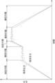
- a set pressure (target pressure) is set in the set pressure setting section 63, and, for example, a setting pattern of the set pressure is set (see FIG. 4).
- the setting pattern is information regarding the relationship between setting pressure and time.
- a piston 20 is inserted into the pressure vessel 10.
- a pressurized object O (for example, a pressure medium O1 and a product to be treated O3) is placed in a pressure vessel 10.
- the heating device 35 starts heating the inside of the pressure vessel 10 (is turned on) before or simultaneously with the start of the pressurization stroke. Then, the pressurizing device 1 performs a pressurizing process, a holding process, and a depressurizing process according to a set pattern (see FIG.
- the pressurizing process may be performed in only one step or in multiple steps (the same applies to the depressurizing process).
- the pressurization process is performed in two stages, and the pressure reduction process is performed in one stage.
- the pressurizing device 1 performs each step in the order of a pressurizing stroke, a holding stroke, a pressurizing stroke, a holding stroke, and a depressurizing step.
- the drive control unit 65 controls the drive device 40 based on the piston axial force information and friction information in each of the pressurizing stroke, holding stroke, and depressurizing stroke.
- the drive control unit 65 controls the movement of the piston body 21 in the axial direction Z by controlling the drive device 40, and controls the internal pressure of the container. Since the container internal pressure is controlled based on the piston axial force information and friction information, the container internal pressure does not need to be directly detected (by the pressure detection member 80). Therefore, the pressure inside the pressure vessel 10 can be accurately controlled without introducing the pressure inside the pressure vessel 10 to the outside of the pressure vessel 10 or without providing the pressure detection member 80 inside the pressure vessel 10. can.
- the drive control unit 65 controls the drive device 40 so that the piston body 21 moves in the insertion direction Z1 in the pressurizing stroke.
- the direction of movement of the piston body 21 in the pressurizing stroke is limited to the insertion direction Z1 (limited to one direction).
- the piston body 21 may reciprocate (described later) (see FIG. 7).
- the internal pressure of the container increases over time. Changes in the internal pressure of the container during the pressurizing stroke are almost limited to those caused by the movement of the piston body 21 (the same applies to the depressurizing stroke).
- the internal pressure of the pressure vessel 10 changes due to a temperature change inside the pressure vessel 10 due to heat from the heating device 35, for example.
- changes in the container internal pressure due to factors other than the movement of the piston body 21 are so small that they can be ignored (even if ignored, there is no or almost no effect on the control of the container internal pressure) (the same applies to the depressurization process).
- the control of the drive device 40 by the drive control unit 65 in the pressurizing stroke is similar to the control of the drive device 40 during movement in the insertion direction Z1 of the reciprocating motion of the piston body 21 in the holding stroke, which will be described later.
- the drive control unit 65 controls the drive device 40 to maintain the container internal pressure substantially constant during the holding stroke.
- the drive control unit 65 causes the piston body 21 to reciprocate at a substantially constant position during the holding stroke (details of the reciprocating operation will be described later).
- the pressurizing device 1 is an isostatic pressurizing device that processes the product O3
- the most important step among the pressurizing step, holding step, and depressurizing step is the holding step.
- the holding process it is important to maintain the processed product O3 at a target temperature and to maintain the pressure for pressurizing the processed product O3 at a set pressure.
- the target is to make the temperature distribution of the processed product O3 uniform at a target temperature (for example, 2000° C.). Therefore, in the holding process, the goal is to maintain the temperature distribution inside the pressure vessel 10 in a steady state (for example, a state in which a constant amount of heat continues to be released from the inside of the heat insulating layer 33 to the outside).
- the converted pressure is not determined to be one value for one value of actual pressure inside the container (for example, pressure P2).
- the value of the piston axial force information deviates (higher or lower) or whether it is the same with respect to the 100% efficiency line L.
- the converted pressure is determined to be one value
- the actual pressure inside the container is not determined to be one value. Therefore, it is difficult to accurately calculate (estimate) the container internal pressure from the converted pressure.
- the piston body 21 is stationary with respect to the pressure vessel 10, it is difficult to accurately control the internal pressure of the vessel.
- the reciprocating motion of the holding stroke is essentially the same as the pressurizing stroke and the depressurizing stroke in terms of movement of the piston body 21 in the insertion direction Z1 and the withdrawal direction Z2. Therefore, it is possible to control the reciprocating movement of the piston body 21 during the holding stroke of actual operation using the friction information obtained from the pressurizing stroke and the depressurizing stroke in the preliminary measurement.
- the friction information used in the holding stroke may be exactly the same as the friction information used in the pressure stroke (or pressure reduction step), or may be information that is a corrected version of the friction information used in the pressure stroke (or pressure reduction step). But that's fine.
- the drive control unit 65 selects friction information corresponding to the direction of movement of the piston body 21 with respect to the pressure vessel 10 (insertion direction Z1 or withdrawal direction Z2).
- the direction of movement of the piston body 21 is obtained directly or indirectly.
- Example 1 of obtaining orientation For example, it is preferable that the direction of movement of the piston body 21 is directly detected by the piston position information detection section 51. In this case, it is possible to reliably detect that the piston body 21 is moving in the axial direction Z.
- the direction of movement of the piston body 21 may be acquired based on a command from the controller 60 to the drive device 40 (for example, a signal indicating the direction in which the piston body 21 is driven).
- the drive control unit 65 selects friction information corresponding to the moving speed of the piston body 21 with respect to the pressure vessel 10 (moving speed in the axial direction Z).
- the moving speed of the piston body 21 is obtained directly or indirectly.
- the moving speed of the piston body 21 may be directly detected by the piston position information detection section 51.
- the moving speed of the piston body 21 in the axial direction Z can be detected reliably.
- the moving speed of the piston body 21 is calculated based on the position of the piston body 21 detected by the piston position information detection unit 51.
- the moving speed of the piston body 21 may be acquired indirectly.
- the moving speed of the piston body 21 may be acquired based on information regarding the drive of the drive device 40 (for example, the flow rate of the working fluid, etc.).
- the moving speed of the piston body 21 may be acquired based on a command from the controller 60 to the drive device 40 (for example, a signal indicating the speed of driving the piston body 21, etc.).
- the movement speed of the reciprocating movement of the piston body 21 is constant (excluding the time when the direction of movement changes and the time in the vicinity), it is not necessary to select friction information corresponding to the movement speed of the piston body 21. None. Further, in the preliminary measurement, it is not necessary to acquire friction information for each of the plurality of patterns of movement speed of the piston body 21. Therefore, the number of preliminary measurements (necessary number of times) for acquiring friction information can be reduced.
- the drive control unit 65 sets (calculates) the content of the instruction to be output to the drive device 40.
- the drive control unit 65 sets the content of the instruction to the drive device 40 based on the piston axial force information and the friction information so that the container internal pressure becomes the set pressure.
- the contents of the instruction to the drive device 40 are, for example, as follows.
- the instruction to the drive device 40 may be information indicating the position of the piston body 21 in the axial direction Z.
- the instruction to the drive device 40 may be information regarding the force with which the drive device 40 presses the piston body 21.
- the instruction to the drive device 40 may be an instruction of the pressure of the working fluid (instruction of the pressure of the head side chamber 41a1) for the drive device 40 to press the piston body 21.
- the instruction to the drive device 40 may be "instruction pressure" (see FIG. 4).
- the indicated pressure is the target value of the internal pressure of the container assuming that there is no piston seal friction force. In reality, there is a piston seal friction force. Therefore, when the piston body 21 moves in the insertion direction Z1, the command pressure is set to be larger than the set pressure. Furthermore, when the piston body 21 moves in the withdrawal direction Z2, the command pressure is set smaller than the set pressure.
- FIG. 5 shows the relationship between the command pressure, the set pressure, and the actual pressure inside the container. In the example shown in FIG. 5, in the holding stroke, command pressures higher than the set pressure and command pressures lower than the set pressure are alternately commanded (with the set pressure in between). Then, the piston body 21 reciprocates, and the actual pressure inside the container repeats an increase (pressurization) and a decrease (depressurization).
- the drive device 40 is driven in accordance with instructions output from the drive control section 65.
- the fluid pressure control section 47 of the drive device 40 controls the pump, the relief mechanism, etc. in accordance with instructions output from the drive control section 65.
- the fluid pressure cylinder 41 then drives the piston body 21 in accordance with the operation of the fluid pressure control section 47.
- the internal pressure of the container is controlled to approach the set pressure.
- Control of the drive device 40 (control of container internal pressure) by the drive control unit 65 can be performed by various methods.
- the friction information may include the relationship between the converted pressure (an example of piston axial force information) shown in FIG. 3 and the pressure correction value data (deviation amount ⁇ ).
- the controller 60 calculates the converted pressure from the detected value of the piston axial force information detection section 53. Further, the controller 60 selects friction information corresponding to the direction of movement of the piston 20. The controller 60 determines pressure correction value data (deviation amount ⁇ ) corresponding to the converted pressure based on the selected friction information.
- the pressure calculation unit 64 calculates (estimates) the container internal pressure based on the converted pressure and the pressure correction value data (deviation amount ⁇ ).
- the pressure calculation unit 64 sets the value obtained by subtracting the deviation amount ⁇ a from the converted pressure as the container internal pressure.
- the pressure calculation unit 64 sets the value obtained by adding the displacement amount ⁇ c to the converted pressure as the container internal pressure.
- the drive control unit 65 then controls the drive device 40 so that the estimated container internal pressure becomes the set pressure.
- the friction information does not need to include the pressure correction value data (deviation amount ⁇ ) itself, and may include information that can be converted into pressure correction value data.
- the friction information may include the relationship between converted pressure and container internal pressure.
- the pressure calculation unit 64 calculates (estimates) the container internal pressure corresponding to the converted pressure based on the friction information.
- the drive control unit 65 then controls the drive device 40 so that the estimated container internal pressure becomes the set pressure.
- the pressure notification section 70 may notify the calculated container internal pressure (the same applies to the pressurization process and the depressurization process).
- the drive control unit 65 controls the drive device 40 so that the piston body 21 performs a reciprocating operation continuously (multiple times).
- the drive control unit 65 may continue the reciprocating operation throughout the holding stroke (from the start to the end) (see FIG. 4).
- the drive control unit 65 continues to move (does not stop) the piston body 21 relative to the pressure vessel 10 except at the moment when the piston body 21 switches the moving direction.
- the drive control unit 65 may temporarily stop the reciprocating movement of the piston body 21 during the holding stroke.
- the drive control unit 65 may stop the reciprocating movement of the piston body 21 only for a short period of time during which the internal pressure of the container changes only slightly (for example, to an extent that does not affect the processing of the processed product O3).
- the drive control unit 65 controls the drive device 40 so that the reciprocating distance (amplitude) in the reciprocating motion of the piston body 21 gradually decreases. Specifically, for example, as shown in FIG. 5, the drive control unit 65 gradually reduces the difference between the command pressure and the set pressure (gradually reduces the amplitude of the set pressure). Then, the amplitude of the reciprocating motion of the piston body 21 gradually decreases, and the amplitude of the change (increase and decrease) in the actual pressure inside the container gradually decreases.
- the reason why it is preferable to gradually reduce the amplitude of the reciprocating motion of the piston body 21 is as follows. For example, immediately after the start of the holding stroke, the situation inside the pressure vessel 10 (specifically, the temperature distribution) changes significantly. Further, at the start of the holding stroke or immediately after the start, the movement of the piston body 21 in one direction stops. At this time, the piston seal friction force changes from dynamic friction force to static friction force. Therefore, immediately after the start of the holding stroke, the accuracy of the friction information may be insufficient. Specifically, for example, the difference between the converted pressure and the actual pressure inside the container (actual deviation amount ⁇ ) shown in FIG. 3 may be different from the pressure correction value data (deviation amount ⁇ ) set as friction information. .
- the drive control unit 65 may gradually reduce the amplitude of the reciprocating motion of the piston body 21 at a timing different from immediately after the start of the holding stroke (such as during the holding stroke).
- the gradual decrease in the amplitude of the reciprocating motion of the piston body 21 (for example, the gradual decrease in the amplitude of the command pressure) can be performed by various methods (modes) (see FIG. 5).
- This gradual decrease in amplitude may be performed from the start of the holding stroke to the middle of the holding stroke.
- the amplitude may be gradually reduced from the start of the holding stroke until the amplitude has decreased to a predetermined value. After that, the amplitude of the reciprocating motion of the piston body 21 may be constant.
- This amplitude may be set (changed) depending on some conditions (for example, the internal pressure of the container, etc.). This amplitude may be set by feedback control. This amplitude may be set by, for example, PID (Proportional Integral Differential) control.
- PID Proportional Integral Differential
- the cycle of the reciprocating movement of the piston body 21 (for example, the cycle of the command pressure) can be set in various ways.
- This period may be constant or substantially constant.
- This period may be changed depending on the magnitude of the amplitude.
- the cycle may be set longer as the amplitude is larger, and the cycle may be set shorter as the amplitude is smaller.
- the period may gradually decrease as the amplitude gradually decreases.
- This cycle may be set depending on some condition other than the amplitude (for example, the internal pressure of the container, etc.).
- the container internal pressure matches or substantially matches the set pressure.
- the internal pressure of the container gradually approaches the set pressure while repeating pressurization and depressurization.
- the center of vibration of the container internal pressure gradually approaches the set pressure from a value lower than the set pressure.
- FIG. 6 shows another example in which the container internal pressure is controlled according to the command pressure from the drive control unit 65 to the drive device 40.
- the internal pressure of the container is higher than the set pressure.
- the drive control unit 65 alternately instructs a command pressure larger than the set pressure and a command pressure smaller than the set pressure with the set pressure in between, and gradually reduces the amplitude of the command pressure ( (Same as Figure 5).
- the center of vibration of the container internal pressure is the same or approximately the same as the set pressure.
- the friction information storage unit 62 stores the friction force between the piston seal 23 and the pressure vessel 10 (piston seal friction force) when the piston body 21 moves relative to the pressure vessel 10. Stores friction information regarding.
- the drive control section 65 controls the drive based on the piston axial force information detected by the piston axial force information detection section 53 and the friction information stored in the friction information storage section 62 (see FIG. 2). Control device 40.
- the drive control unit 65 causes the piston body 21 to reciprocate with respect to the pressure vessel 10 in a holding stroke that controls the pressure inside the pressure vessel 10 to be kept constant.
- the drive device 40 is controlled as follows.
- the drive control section 65 controls the drive device 40 based on the friction information stored in the friction information storage section 62 (see FIG. 2).
- This friction information is friction information when the piston body 21 moves relative to the pressure vessel 10.
- the drive control unit 65 reciprocates (that is, moves) the piston body 21 with respect to the pressure vessel 10 in the holding stroke (see FIG. 5). Therefore, friction information when the piston body 21 moves relative to the pressure vessel 10 can be applied to control the drive device 40 during the holding stroke. Therefore, the pressurizing device 1 can control the pressure inside the pressure vessel 10 (container internal pressure) in the holding stroke with higher precision than when the piston body 21 is kept stationary with respect to the pressure vessel 10 in the holding stroke.
- the friction information storage unit 62 stores friction information when the piston body 21 moves in the insertion direction Z1 with respect to the pressure vessel 10, and friction information when the piston body 21 moves with respect to the pressure vessel 10. Friction information when moving in the pull-out direction Z2 is stored.
- the drive control unit 65 selects friction information corresponding to the direction of movement of the piston body 21 with respect to the pressure vessel 10, and controls the drive device 40 based on the selected friction information.
- the above [Configuration 2] provides the following effects.
- the piston seal friction force may differ depending on the direction of movement of the piston body 21 relative to the pressure vessel 10 (see FIG. 3).
- the drive device 40 is controlled based on friction information corresponding to the direction of movement of the piston body 21. Therefore, the pressurizing device 1 can control the internal pressure of the container with higher accuracy.
- the friction information storage unit 62 (see FIG. 2) stores friction information for each of a plurality of patterns of movement speeds of the piston body 21 with respect to the pressure vessel 10.
- the drive control unit 65 selects friction information corresponding to the moving speed of the piston body 21 with respect to the pressure vessel 10, and controls the drive device 40 based on the selected friction information.
- the above [Structure 3] provides the following effects.
- the piston seal friction force may vary depending on the moving speed of the piston body 21 with respect to the pressure vessel 10.
- the drive device 40 is controlled based on the friction information corresponding to the moving speed of the piston body 21. Therefore, the pressurizing device 1 can control the internal pressure of the container with higher accuracy.
- the pressurizing device 1 includes a piston position information detection section 51.
- the piston position information detection unit 51 detects position information of the piston body 21 with respect to the pressure vessel 10.
- the drive control unit 65 controls the drive device 40 based on friction information corresponding to the direction of movement of the piston body 21 with respect to the pressure vessel 10.
- the piston position information detection unit 51 detects the position information of the piston body 21 with respect to the pressure vessel 10, thereby reliably (directly) determining the direction of movement of the piston body 21 with respect to the pressure vessel 10. Can be detected. As a result, the pressurizing device 1 can control the internal pressure of the container with higher accuracy.
- the drive control unit 65 controls the drive device 40 based on friction information corresponding to the moving speed of the piston body 21 with respect to the pressure vessel 10.
- the piston position information detection unit 51 reliably (directly) detects the moving speed of the piston body 21 with respect to the pressure vessel 10 by detecting the position information of the piston body 21 with respect to the pressure vessel 10. Can be detected. As a result, the pressurizing device 1 can control the internal pressure of the container with higher accuracy.
- the piston axial force information detection section 53 includes a strain gauge 53a.
- the strain gauge 53a is attached to the piston body 21 and detects the strain of the piston body 21.
- the strain gauge 53a of the above [Configuration 5] can directly detect piston axial force information. Therefore, the accuracy of piston axial force information can be improved. Specifically, for example, when the piston axial force information is the pressure of the working fluid of the drive device 40 that drives the piston body 21 (described later), the piston axial force information is influenced by the frictional force of the ram seal 41d. On the other hand, in the above [Configuration 5], the piston axial force information acquired from the strain gauge 53a is not affected by the frictional force of the ram seal 41d. Since the piston axial force information can be directly detected by the strain gauge 53a, the drive control unit 65 (see FIG. 2) controls the drive device 40 based on the piston axial force information and friction information (as described in [Configuration 1-1] above). ) can be performed with greater precision. As a result, the pressurizing device 1 can control the internal pressure of the container with higher accuracy.
- the drive control unit 65 controls the drive device 40 so that the reciprocating distance in the reciprocating movement of the piston body 21 with respect to the pressure vessel 10 gradually decreases in the holding stroke.
- the drive control unit 65 can gradually reduce the difference between the target internal pressure of the container (for example, the above-mentioned "set pressure") and the actual internal pressure of the container. Therefore, the drive control unit 65 (see FIG. 2) can control the container internal pressure to appropriately approach the target container internal pressure. As a result, the pressurizing device 1 can control the internal pressure of the container with higher accuracy.
- the pressure detection member 80 is removable from the pressure vessel 10. Therefore, for example, even if the pressure detection member 80 or the pressure derivation member De cannot withstand long-term actual operation, the pressure detection member 80 or the pressure derivation member De may be removed after the friction information is acquired and before the actual operation. De can be removed from the pressure vessel 10.
- the pressure detection member 80 can more directly detect the actual pressure inside the pressure vessel 10 in a state where it is disposed inside the pressure vessel 10. As a result, the accuracy of friction information can be improved. As a result, the pressurizing device 1 can control the internal pressure of the container with higher accuracy.
- the pressure detection member 80 is removable from the pressure vessel 10. Therefore, even if, for example, the pressure detection member 80 cannot withstand long-term actual operation, the pressure detection member 80 should be removed from the pressure vessel 10 after friction information is acquired and before actual operation. Can be done.
- the piston axial force information detected by the piston axial force information detection unit 53 includes information that directly detects the axial force of the piston body 21, or information that can be converted from this information. Specifically, for example, the piston axial force information includes information regarding the detected value of the strain gauge 53a.
- the piston axial force information detected by the piston axial force information detection unit 53 may include information regarding the force with which the drive device 40 presses the piston body 21 in the insertion direction Z1. For example, if the drive device 40 is a device that drives the piston body 21 using fluid pressure, the piston axial force information may include information regarding the pressure of the working fluid for pressing the piston body 21 in the insertion direction Z1. .
- the piston axial force information detected by the piston axial force information detection unit 53 is information regarding the pressure of the working fluid for pressing the piston body 21 in the insertion direction Z1.
- the piston axial force information may be information regarding the pressure of the working fluid in the head side chamber 41a1.
- the piston axial force information may be information regarding the fluid pressure detected by the fluid pressure detection section 45.
- the piston axial force information detection section 53 for detecting piston axial force information and the fluid pressure detection section 45 for controlling the drive device 40 may be used together. Note that the piston axial force information detection section 53 does not have to be used also as the fluid pressure detection section 45.
- a piston axial force information detection unit 53 that detects information regarding the pressure of the working fluid for pressing the piston body 21 in the insertion direction Z1 as piston axial force information is provided separately from the fluid pressure detection unit 45. It's okay. Below, a case will be mainly described in which the piston axial force information detection section 53 is also used as the fluid pressure detection section 45.
- friction information that takes into account the ram seal friction force is acquired in the preliminary measurement. More specifically, in the preliminary measurement, information regarding the fluid pressure detected by the piston axial force information detection unit 53 (for example, the fluid pressure detection unit 45) is acquired as piston axial force information including the influence of the ram seal friction force. The relationship between this piston axial force information and the actual pressure inside the container (preliminary measurement acquisition relationship R (see FIG. 3)) is acquired. Based on this pre-measurement acquisition relationship R, friction information stored in the friction information storage section 62 (see FIG. 2) is acquired.
- the drive control unit 65 controls the drive device 40 based on the piston axial force information including the influence of the ram seal friction force and the friction information including the ram seal friction force.
- the drive control section 65 can control the drive device 40 similarly to the above embodiment.
- the pressurizing device 1 can accurately control the internal pressure of the container.
- the conditions that affect friction information as similar as possible between preliminary measurement and actual operation.
- friction information may be acquired at various working fluid temperatures. Then, during actual operation, the drive control unit 65 (see FIG. 2) may select friction information corresponding to the detected temperature of the working fluid and control the drive device 40 based on the selected friction information.
- the drive device 40 includes a fluid pressure cylinder 41, a fluid pressure detection section 45, and a fluid pressure control section 47.
- the fluid pressure cylinder 41 moves the piston body 21 using fluid pressure.
- the fluid pressure detection unit 45 detects the fluid pressure supplied to the fluid pressure cylinder 41.
- the fluid pressure control section 47 controls the operation of the fluid pressure cylinder 41 based on the fluid pressure detected by the fluid pressure detection section 45 .
- the piston axial force information detected by the piston axial force information detection section 53 includes the fluid pressure detected by the fluid pressure detection section 45.
- the piston axial force information includes the fluid pressure of the hydraulic oil detected by the fluid pressure detection unit 45 for controlling the operation of the fluid pressure cylinder 41. Therefore, the piston axial force information detection section 53 and the fluid pressure detection section 45 can be used together. Therefore, apart from the fluid pressure detection section 45 for controlling the operation of the fluid pressure cylinder 41, there is no need to provide a sensor (for example, the strain gauge 53a, etc.) for acquiring piston axial force information. Therefore, the pressurizing device 1 can have a simple configuration.
- a piston axial force information detection section 53 (for example, a strain gauge 53a) separate from the fluid pressure detection section 45 is provided, maintenance of each of the fluid pressure detection section 45 and the piston axial force information detection section 53 is required. Become. Specifically, for example, since the strain gauge 53a deteriorates over time, maintenance of the strain gauge 53a is required. On the other hand, when the piston axial force information detection section 53 and the fluid pressure detection section 45 are used together, the effort and time required for maintenance work can be reduced.
- various parameters may be set in advance in the controller 60, or may be set directly by manual operation by an operator.
- Various parameters may be calculated by the controller 60 based on information detected by a sensor (for example, the piston axial force information detection unit 53, etc.).
- various parameters may not be changed, may be changed manually, or may be changed automatically by the controller 60 depending on some conditions.
- each component may have only a portion of each feature (functionality, arrangement, shape, operation, etc.).
- a pressurizing device includes a pressure vessel, a piston body fitted into the pressure vessel so as to be movable in an insertion direction and a withdrawal direction with respect to the pressure vessel, and the piston body.
- Piston axial force information regarding a piston seal provided on a main body and sealing a gap between the piston main body and the pressure vessel, and an axial force applied to the piston main body that is an axial force in a moving direction of the piston main body with respect to the pressure vessel.
- a piston axial force information detection unit that detects the piston axial force information, a drive device that moves the piston body relative to the pressure vessel, and a piston seal and the pressure vessel when the piston body moves relative to the pressure vessel.
- a drive control section that controls the drive device.
- the drive control unit controls the drive device so that the piston body reciprocates with respect to the pressure vessel during a holding stroke in which the pressure inside the pressure vessel is controlled to be kept constant.
- the friction information storage unit stores the friction information when the piston body moves in the insertion direction with respect to the pressure vessel, and the friction information with respect to the pressure vessel.
- the friction information when the piston body moves in the withdrawal direction is stored, and the drive control unit selects the friction information corresponding to the direction of movement of the piston body with respect to the pressure vessel, and selects the friction information that corresponds to the direction of movement of the piston body with respect to the pressure vessel.
- the driving device may be controlled based on.
- the friction information storage unit stores the friction information for each of a plurality of patterns of movement speed of the piston body with respect to the pressure vessel, and the drive control unit The friction information corresponding to the moving speed of the piston body with respect to the pressure vessel may be selected, and the drive device may be controlled based on the selected friction information.
- the drive device includes a fluid pressure cylinder that moves the piston body using fluid pressure, and a fluid pressure cylinder that moves the piston body using fluid pressure.
- a fluid pressure detection section that detects the fluid pressure
- a fluid pressure control section that controls the operation of the fluid pressure cylinder based on the fluid pressure detected by the fluid pressure detection section, and the piston axial force information detection section detects
- the piston axial force information may include fluid pressure detected by the fluid pressure detection section.
- the pressurizing device further includes a pressure detection member that is removably provided from the pressure vessel and detects the pressure inside the pressure vessel,
- the friction information includes the piston axial force information detected by the piston axial force information detection unit when the piston body moves relative to the pressure vessel, and the inside of the pressure vessel detected by the pressure detection member. It may be obtained based on the pressure of
- the pressure detection member is disposed inside the pressure vessel so as to be removable from the inside of the pressure vessel, and the friction information indicates that the pressure detection member is It may also be acquired while being placed inside the .
Landscapes
- Engineering & Computer Science (AREA)
- Mechanical Engineering (AREA)
- Physics & Mathematics (AREA)
- Fluid Mechanics (AREA)
- Actuator (AREA)
- Control Of Presses (AREA)
- Press Drives And Press Lines (AREA)
- Pressure Vessels And Lids Thereof (AREA)
Abstract
Description
後述するように、ピストン20は、圧力容器10に対して移動する。圧力容器10に対するピストン20の移動方向を、軸方向Zとする。軸方向Zにおいて、ピストン20が圧力容器10に差し込まれる向き(側)を差込方向Z1とし、その逆向き(逆側)を引出方向Z2とする。引出方向Z2は、ピストン20が圧力容器10から引き出される側である。軸方向Zは、例えば上下方向(鉛直方向)でもよく、水平方向でもよく、上下方向および水平方向に対して傾いた方向でもよい。軸方向Zが上下方向の場合、差込方向Z1は、上向きでもよく、下向きでもよい(引出方向Z2も同様)。ピストン20の中心を通る軸であって軸方向Zに延びる軸を、中心軸Aとする。中心軸Aに直交する平面上の仮想円(図示なし)であって中心軸Aを中心とする仮想円の直径方向を「径方向」とする。
例えば、圧力容器10の内部から外部に高圧(例えば1000MPa級など)の圧力媒体O1を導出するための、圧力導出部材De(例えば配管)が設けられる。そして、圧力検出部材80(後述)が、圧力導出部材Deで導出された圧力(またはこの圧力が減圧された圧力)を、圧力容器10の外部で検出する。この場合、圧力導出部材Deが、短寿命となり、長時間の実運転には耐えられないおそれがある。
例えば、圧力検出部材80が、圧力容器10の内部に配置され、圧力媒体O1の圧力を検出する。すると、圧力検出部材80が、長時間の実運転には耐えられないおそれがある。そのため、加圧装置1の実運転(後述)時には、容器内圧を直接的に検出することはできない、または困難である。そこで、加圧装置1の実運転時には、ピストン軸力情報検出部53が、容器内圧に換算可能なピストン軸力情報を検出する。そして、容器内圧が、ピストン軸力情報などに基づいて制御される(制御の詳細は後述)。
加圧装置1は、以下のように作動するように構成される。加圧装置1では、事前測定と、実運転(通常運転)と、が行われる。加圧装置1のうちコントローラ60以外の構成要素については図1を参照し、コントローラ60およびコントローラ60の構成要素については図2を参照して説明する。
事前測定は、摩擦情報記憶部62に記憶される摩擦情報を取得するための、測定(加圧装置1の運転)である。事前測定がおこなわれるときの加圧装置1は、摩擦情報を取得するための摩擦情報取得装置である。事前測定は、実運転よりも前に(事前に)行われる。事前測定では、圧力検出部材80が、圧力容器10の内部または外部に設けられる。事前測定では、ピストン軸力情報検出部53に検出されるピストン軸力情報と、圧力検出部材80に検出される内圧(「容器内実圧」という)と、の関係(事前測定取得関係R(図3参照))が測定される。
図3に示す事前測定取得関係Rは、実運転時のピストン軸力情報の範囲(使用軸力範囲)にわたって取得される。事前測定取得関係Rは、使用軸力範囲の全体を含むように取得される。例えば、ピストン軸力情報が、ピストン本体21の軸力から容器内圧に換算された換算圧力(後述)である場合は、事前測定取得関係Rは、実運転時の換算圧力の範囲(使用換算圧力範囲)にわたって取得される。事前測定取得関係Rは、実運転時の容器内実圧の範囲(使用容器内実圧範囲)にわたって取得される。事前測定取得関係Rは、使用容器内実圧範囲の全体を含むように取得される。
事前測定では、圧力容器10に対してピストン本体21が軸方向Zに移動するときの事前測定取得関係Rが取得される。事前測定取得関係Rは、圧力容器10に対するピストン本体21の移動の向きごとに取得されることが好ましい。さらに詳しくは、後述する「差込方向Z1の移動での関係Ra」と、後述する「引出方向Z2の移動での関係Rc」と、が取得されることが好ましい。事前測定では、圧力容器10に対してピストン本体21が静止しているときの事前測定取得関係Rである「静止時の関係Rb」が、取得されてもよい。
事前測定では、ある1パターンのピストン本体21の移動速さでの事前測定取得関係Rが取得されてもよい。この場合、上記「1パターン」の移動速さは、実運転時のピストン本体21の移動速さと同じまたは略同じ移動速さであることが好ましい。事前測定では、複数パターンのピストン本体21の移動速さそれぞれでの事前測定取得関係Rが取得されてもよい。この場合、図3に示すようなグラフが複数パターン取得される。
事前測定取得関係R(ピストン軸力情報と、容器内実圧との関係)の具体例について説明する。図3に示す例では、ピストン軸力情報は、換算圧力である。換算圧力は、例えば次のように算出される。歪みゲージ53aから得られたピストン本体21の歪み量から、ピストン本体21の軸力が算出される。なお、上記のように、ピストン本体21の軸力は、ピストンシール摩擦力とピストン本体21が受ける圧力による力との和である。そして、ピストン本体21の軸力をピストン本体21の受圧面積で割った値が、換算圧力である。上記「受圧面積」は、ピストン本体21のうち、加圧対象物O(圧力媒体O1)から軸方向Zに圧力を受ける部分の面積である。具体的には例えば、受圧面積は、差込方向Z1から見たときのピストン本体柱状部21aの面積である。
事前測定では、圧力検出部材80が容器内実圧を検出する。圧力検出部材80は、圧力容器10の内部に配置されても、圧力容器10の外部に配置されてもよい。
事前測定と実運転とで、摩擦情報に影響を与える条件をできるだけ同じ条件にすることが好ましい。例えば、ピストンシール23の温度は、事前測定と実運転とで、できるだけ同じであることが好ましい。具体的には例えば、実運転時には、断熱層33の内部が2000℃となる場合は、圧力容器10の内部かつ断熱層33の外部は約100℃などになり、ピストンシール23も約100℃になる場合がある。この場合、事前測定時にも、ピストンシール23の温度を100℃または約100℃とすることが好ましい。摩擦情報に与える影響が小さければ、実運転時にピストンシール23が100℃などになる場合に、事前測定時にピストンシール23が室温(約20℃など)にされてもよい。なお、上記の温度の値は一例にすぎず、上記の温度は様々に値に設定可能である。摩擦情報に与える影響がない、または略ない条件については、事前測定と実運転とで同じ条件にする必要はない。例えば、事前測定時には、圧力容器10の内部に、圧力容器内部材30や処理品O3が設けられる必要はない。
摩擦情報記憶部62が記憶する摩擦情報は、圧力容器10に対してピストン本体21が移動するときの、ピストンシール摩擦力に関する情報を含む。摩擦情報は、事前測定によって得られた事前測定取得関係Rに基づいて取得(設定)される。摩擦情報は、事前測定取得関係Rでもよく、事前測定取得関係Rから算出(導出)された情報でもよい。
摩擦情報は、必要な時に校正(修正、更新)されてもよい。例えば、実運転が行われた後、必要に応じて事前測定が再度行われ、摩擦情報が校正されてもよい。この場合、加圧装置1は、精度の高い容器内圧の制御を維持することができる。
実運転は、摩擦情報に基づいて容器内圧を制御する、加圧装置1の運転である。加圧装置1が処理品O3を処理する装置である場合、実運転は、処理品O3を処理するための運転である。加圧装置1が、加圧対象物Oの状態を測定する装置である場合、実運転は、加圧対象物Oの状態を測定するための運転である。
実運転の手順の概要は、例えば次の通りである。設定圧力設定部63に、設定圧力(目標圧力)が設定され、例えば設定圧力の設定パターンが設定される(図4参照)。設定パターンは、設定圧力と時間との関係に関する情報である。ピストン20が、圧力容器10内に差し込まれる。加圧対象物O(例えば圧力媒体O1および処理品O3)が、圧力容器10内に入れられる。加熱装置35が、加圧行程の開始前または開始と同時に、圧力容器10内の加熱を開始する(オンにされる)。そして、加圧装置1は、設定パターン(図4参照)に従って、加圧行程、保持行程、および減圧工程を行う。加圧行程は、1段階のみ行われてもよく、複数段階行われてもよい(減圧工程も同様)。図4に示す例では、加圧行程が2段階行われ、減圧工程が1段階行われる。図4に示す例では、加圧装置1は、加圧行程、保持行程、加圧行程、保持行程、減圧工程、の順で各工程を行う。
駆動制御部65は、加圧行程、保持行程、および減圧行程のそれぞれの行程において、ピストン軸力情報および摩擦情報に基づいて、駆動装置40を制御する。駆動制御部65は、駆動装置40を制御することで、ピストン本体21の軸方向Zの移動を制御し、容器内圧を制御する。ピストン軸力情報および摩擦情報に基づいて容器内圧が制御されるので、容器内圧が直接的に(圧力検出部材80により)検出される必要はない。よって、圧力容器10の内部の圧力を、圧力容器10の外部に導出しなくても、また、圧力容器10の内部に圧力検出部材80を設けなくても、容器内圧を精度良く制御することができる。
駆動制御部65は、加圧行程において、ピストン本体21が差込方向Z1に移動するように、駆動装置40を制御する。加圧行程でのピストン本体21の移動の向きは、差込方向Z1に限定される(一方向に限定される)。なお、加圧行程において、ピストン本体21が往復動作する場合があってもよい(後述)(図7参照)。加圧行程において、容器内圧は、時間とともに増加する。加圧行程での容器内圧の変化は、ほぼ、ピストン本体21の移動によるものに限定される(減圧工程も同様)。なお、厳密には、加圧行程において、例えば加熱装置35の熱などによる圧力容器10の内部の温度変化により、容器内圧が変化する。しかし、ピストン本体21の移動によるもの以外の要因による容器内圧の変化は、無視できる程度に小さい(無視しても容器内圧の制御に影響がない、または略ない)(減圧工程も同様)。加圧行程における駆動制御部65による駆動装置40の制御は、後述する保持行程でのピストン本体21の往復動作のうち差込方向Z1への移動時の駆動装置40の制御と同様である。
駆動制御部65は、減圧行程において、ピストン本体21が引出方向Z2に移動するように、駆動装置40を制御する。減圧行程でのピストン本体21の移動の向きは、引出方向Z2に限定される(一方向に限定される)。なお、減圧行程において、ピストン本体21が往復動作する場合があってもよい。減圧行程において、容器内圧は、時間とともに減少する。減圧行程における駆動制御部65による駆動装置40の制御は、後述する保持行程でのピストン本体21の往復動作のうち引出方向Z2への移動時の駆動装置40の制御と同様である。
駆動制御部65は、保持行程において、容器内圧を略一定に保持するように、駆動装置40を制御する。駆動制御部65は、保持行程において、ピストン本体21を略一定の位置で往復動作させる(往復動作の詳細は後述)。
圧力容器10に対してピストン本体21が静止しているときには、容器内圧を精度良く制御することは困難である。その理由には、容器内圧の推定が困難であること(下記[問題の例1])、および、容器内圧の変化に対するピストン本体21の追従が困難であること(下記[問題の例2])がある。
図3に示すように、事前測定で取得可能な静止時の関係Rbでは、ピストン本体21は一定位置にとどまり、容器内実圧は一定の圧力P2となっている。しかし、実運転時は、ピストン本体21の位置が一定でも、容器内実圧は一定にならず、変化する(ふらつく)。例えば、圧力容器10の内部の温度は、時間的にも、分布にも、不可避の変化がある。例えば、加熱装置35が、加圧対象物Oなどを加熱すると、圧力容器10の内部の温度分布が変化する。また、このとき、圧力容器10の内部の平均温度は、時間とともに上がっていく。圧力容器10の内部の温度が変化すると、ボイルシャルルの法則に従って、容器内圧も変化する。よって、ピストン本体21の位置が一定でも、容器内実圧は一定とはならない。
一般的に、静摩擦力は、動摩擦力より大きい。そのため、ピストン本体21が圧力容器10に対して静止しているときに、容器内圧が変化しても、ピストン本体21は、圧力容器10に対して静止したままとなりやすい。さらに詳しくは、圧力容器10の内部の温度が上がった場合、ボイルシャルルの法則により、容器内圧は上がろうとする。このとき、ピストン本体21が受ける容器内圧による力よりもピストンシール摩擦力が小さければ、ピストン本体21が引出方向Z2に移動し、容器内圧が下がり、容器内圧が設定圧に近づく。しかし、ピストンシール摩擦力が、ピストン本体21が受ける容器内圧による力以上であれば、圧力容器10の内部の温度が上がっても、ピストン本体21は引出方向Z2に移動しない。すると、容器内圧が上がり、容器内圧が設定圧からずれる。また、圧力容器10の内部の温度が下がる場合は、容器内圧が下がり、容器内圧が設定圧からずれる。その結果、圧力容器10に対してピストン本体21が静止しているときには、容器内圧を精度良く制御することは困難である。
そこで、本実施形態の加圧装置1は、保持行程において、次のように作動するように構成される。駆動制御部65は、圧力容器10に対してピストン本体21が往復動作(軸方向Zに往復動作)するように、駆動装置40を制御する。駆動装置40は、圧力容器10に対してピストン本体21を往復動作させる。ピストン本体21は、圧力容器10に対して往復動作する。ピストン本体21は、軸方向Zに小刻みに(細かく)往復動作する。
圧力容器10に対してピストン本体21が往復動作するので、ピストン本体21が軸方向Zに移動するときの摩擦情報を利用することができる。ピストン本体21が軸方向Zに移動するときの摩擦情報では、ピストン軸力情報の値が1つに決まれば、容器内圧が1つの値に決まる(図3参照)。よって、容器内圧を精度良く算出(推定)することができる。その結果、容器内圧を精度良く制御することができる。
また、圧力容器10に対してピストン本体21が往復動作するので、ピストンシール摩擦力は、静摩擦力よりも小さい動摩擦力になる。よって、圧力容器10内の温度変化による容器内圧の変化に対して、ピストン本体21の位置が容易に追従することができる。例えば圧力容器10の内部の温度が上がり、容器内圧が上がろうとすると、ピストン本体21が(例えばピストン本体21の往復動作の中心位置が)引出方向Z2に移動しやすい。また、圧力容器10の内部の温度が下がり、容器内圧が下がろうとすると、ピストン本体21が(例えばピストン本体21の往復動作の中心位置が)差込方向Z1に移動しやすい。よって、容器内圧の変化に対して、ピストン本体21の位置が容易に追従するので、容器内圧を設定圧力に近づけることができる。その結果、容器内圧を精度良く制御することができる。
上記のように、駆動制御部65は、ピストン軸力情報および摩擦情報に基づいて、駆動装置40を制御する。この制御の詳細は次の通りである。
ピストン位置情報検出部51が、ピストン軸力情報(例えばピストン本体21の歪みなど)を検出し、検出値をコントローラ60に出力する。例えば、コントローラ60は、ピストン軸力情報検出部53の検出値から、換算圧力(図3参照)(ピストン軸力情報の一例)を算出する。
駆動制御部65は、摩擦情報記憶部62から摩擦情報を取得する。ここで、事前測定では、加圧装置1が加圧行程を行うことで差込方向Z1の移動での関係Ra(図3参照)が得られ、加圧装置1が減圧行程を行うことで引出方向Z2の移動での関係Rc(図3参照)が得られる。実運転での保持行程でのピストン本体21の往復動作は、ピストン本体21の差込方向Z1の移動と、ピストン本体21の引出方向Z2の移動と、の繰り返しである。よって、保持行程の往復動作は、ピストン本体21の差込方向Z1および引出方向Z2の移動という点では、加圧行程および減圧行程と本質的に変わらない。よって、事前測定での加圧行程および減圧行程から得られた摩擦情報を用いて、実運転の保持行程でのピストン本体21の往復動作を制御することが可能である。なお、保持行程で用いられる摩擦情報は、加圧行程(または減圧工程)で用いられる摩擦情報と全く同じ情報でもよく、また、加圧行程(または減圧工程)で用いられる摩擦情報を補正した情報でもよい。
例えば、ピストン本体21の移動の向きは、ピストン位置情報検出部51に直接的に検出されることが好ましい。この場合は、ピストン本体21が軸方向Zに移動していることを確実に検出することができる。
ピストン本体21の移動の向きは、間接的に取得されてもよい。
ピストン本体21の移動の向きは、駆動装置40の駆動に関する情報(例えば、作動流体の流れの向き、圧力など)に基づいて取得されてもよい。
ピストン本体21の移動の向きは、コントローラ60から駆動装置40への指令(例えばピストン本体21の駆動の向きを示す信号など)に基づいて取得されてもよい。
ピストン本体21の移動速さは、ピストン位置情報検出部51に直接的に検出されてもよい。この場合、ピストン本体21の軸方向Zの移動速さを確実に検出することができる。例えば、ピストン位置情報検出部51に検出されたピストン本体21の位置に基づいてピストン本体21の移動速さが算出される。
ピストン本体21の移動速さは、間接的に取得されてもよい。
ピストン本体21の移動速さは、駆動装置40の駆動に関する情報(例えば、作動流体の流速など)に基づいて取得されてもよい。
ピストン本体21の移動速さは、コントローラ60から駆動装置40への指令(例えばピストン本体21の駆動の速度を示す信号など)に基づいて取得されてもよい。
駆動制御部65は、駆動装置40に出力する指示の内容を設定(算出)する。駆動制御部65は、ピストン軸力情報および摩擦情報に基づいて、容器内圧が、設定圧力になるように、駆動装置40への指示の内容を設定する。駆動装置40への指示の内容は、例えば次の通りである。
駆動装置40への指示は、ピストン本体21の軸方向Zの位置を示す情報でもよい。
駆動装置40への指示は、駆動装置40がピストン本体21を押圧する力に関する情報でもよい。
駆動装置40への指示は、駆動装置40がピストン本体21を押圧するための、作動流体の圧力の指示(ヘッド側室41a1の圧力の指示)でもよい。
駆動装置40への指示は、「指示圧力」(図4参照)でもよい。指示圧力は、ピストンシール摩擦力が無いと仮定したときの、容器内圧の目標値である。実際にはピストンシール摩擦力がある。よって、差込方向Z1へのピストン本体21の移動時には、指示圧力は、設定圧力よりも大きく設定される。また、引出方向Z2へのピストン本体21の移動時には、指示圧力は、設定圧力よりも小さく設定される。具体的には例えば、図5に、指示圧力と、設定圧力と、容器内実圧と、の関係を示す。図5に示す例では、保持行程では、設定圧力よりも大きい指示圧力と、設定圧力よりも小さい指示圧力と、が交互に(設定圧力を挟むように)指示される。すると、ピストン本体21が往復動作し、容器内実圧が、上昇(加圧)と降下(減圧)とを繰り返す。
例えば、摩擦情報は、図3に示す換算圧力(ピストン軸力情報の一例)と、圧力補正値データ(ズレ量α)と、の関係を含んでもよい。この場合、コントローラ60が、ピストン軸力情報検出部53の検出値から換算圧力を算出する。また、コントローラ60が、ピストン20の移動の向きに対応する摩擦情報を選択する。コントローラ60が、選択した摩擦情報に基づいて、換算圧力に対応する圧力補正値データ(ズレ量α)を決定する。圧力演算部64が、換算圧力と圧力補正値データ(ズレ量α)とに基づいて、容器内圧を算出(推定)する。具体的には例えば、ピストン本体21が差込方向Z1に移動するときは、圧力演算部64は、換算圧力からズレ量αaを引いた値を、容器内圧とする。ピストン本体21が引出方向Z2に移動するときは、圧力演算部64は、換算圧力にズレ量αcを足した値を、容器内圧とする。そして、駆動制御部65は、推定された容器内圧が、設定圧力になるように、駆動装置40を制御する。
摩擦情報は、圧力補正値データ(ズレ量α)そのものを含む必要はなく、圧力補正値データに換算可能な情報を含んでもよい。例えば、摩擦情報は、換算圧力と容器内圧との関係を含んでもよい。この場合、圧力演算部64は、摩擦情報に基づいて、換算圧力に対応する容器内圧を算出(推定)する。そして、駆動制御部65は、推定された容器内圧が、設定圧力になるように、駆動装置40を制御する。
摩擦情報は、換算圧力を含む必要はない。例えば、摩擦情報は、ピストン本体21の歪み量(ピストン軸力情報の一例)と、容器内圧との関係を含んでもよい。この場合、圧力演算部64は、摩擦情報に基づいて、歪みゲージ53aに検出された歪み量に対応する容器内圧を算出(推定)する。そして、駆動制御部65は、推定された容器内圧が、設定圧力になるように、駆動装置40を制御する。なお、上記の容器内圧の制御方法は具体例にすぎず、様々に容器内圧を制御することが可能である。
圧力演算部64が容器内圧を算出(推定)した場合に、圧力通知部70は、算出された容器内圧を通知してもよい(加圧行程および減圧工程も同様)。
駆動制御部65は、ピストン本体21が往復動作を連続的に(複数回)行うように、駆動装置40を制御する。駆動制御部65は、保持行程の全体で(開始時から終了時までにわたって)、往復動作を継続させてもよい(図4参照)。駆動制御部65は、ピストン本体21が移動方向を切り替える瞬間以外は、圧力容器10に対するピストン本体21を移動させ続ける(停止させない)。なお、駆動制御部65は、保持行程において、ピストン本体21の往復動作を一時的に停止させる場合があってもよい。例えば、容器内圧が微小にのみ変化する程度(例えば処理品O3の処理に影響を与えない程度)の短時間のみ、駆動制御部65は、ピストン本体21の往復動作を停止させてもよい。
駆動制御部65は、ピストン本体21の往復動作における往復距離(振幅)が漸減するように駆動装置40を制御することが好ましい。具体的には例えば、図5に示すように、駆動制御部65は、指示圧力と設定圧力との差を漸減させる(設定圧力の振幅を漸減させる)。すると、ピストン本体21の往復動作の振幅が漸減し、容器内実圧の変化(上昇および降下)の振幅が漸減する。
この振幅の漸減は、保持行程の開始時から終了時にわたって行われてもよい。
この振幅の漸減は、保持行程の開始時から、保持行程の途中まで行われてもよい。例えば、この振幅の漸減は、保持行程の開始時から、振幅が所定の大きさまで小さくなったときまで行われてもよい。その後、ピストン本体21の往復動作の振幅が一定とされてもよい。
この振幅は、時間に対して比例して減少してもよく、比例とは異なる関係で減少してもよい。
この振幅は、何らかの条件(例えば容器内圧など)に応じて設定されても(変えられても)よい。この振幅は、フィードバック制御により設定されてもよい。この振幅は、例えばPID(Proportional Integral Differential)制御などにより設定されてもよい。
この周期は、一定でもよく、略一定でもよい。
この周期は、振幅の大きさに応じて変えられてもよい。例えば、振幅が大きいほど周期が長く設定され、振幅が小さいほど周期が短く設定されてもよい。例えば、振幅の漸減に応じて、周期が漸減してもよい。
この周期は、振幅以外の何らかの条件(例えば容器内圧など)に応じて設定されてもよい。
駆動制御部65による容器内圧の制御の一例として、駆動制御部65から駆動装置40への指示圧力に応じて、容器内圧が制御される場合について説明する。上記のように、図5に示す例では、駆動制御部65は、設定圧力よりも大きい指示圧力と、設定圧力よりも小さい指示圧力と、を交互に指示し、指示圧力の振幅を漸減させる。その結果、ピストン本体21の往復動作の振幅が漸減し、容器内圧の振幅が漸減する。
上記実施形態では、ピストン軸力情報検出部53が検出するピストン軸力情報は、ピストン本体21の軸力を直接的に検出した情報、またはこの情報から換算可能な情報を含む。具体的には例えば、ピストン軸力情報は、歪みゲージ53aの検出値に関する情報を含む。一方、ピストン軸力情報検出部53が検出するピストン軸力情報は、駆動装置40がピストン本体21を差込方向Z1に押圧する力に関する情報を含んでもよい。例えば、駆動装置40が、流体圧によりピストン本体21を駆動する装置である場合、ピストン軸力情報は、ピストン本体21を差込方向Z1に押圧するための作動流体の圧力に関する情報を含んでもよい。
上記実施形態および変形例は、さらに様々に変形されてもよい。例えば、上記実施形態などの構成要素の数が変更されてもよく、構成要素の一部が設けられなくてもよい。例えば、構成要素どうしの固定や連結などは、直接的でも間接的でもよい。例えば、図2に示す各構成要素の接続は変更されてもよい。図1に示す各構成要素の配置は、変更されてもよい。例えば、構成要素の包含関係は様々に変更されてもよい。例えば、ある上位の構成要素に含まれる下位の構成要素として説明したものが、この上位の構成要素に含まれなくてもよく、他の構成要素に含まれてもよい。例えば、互いに異なる複数の部材や部分として説明したものが、一つの部材や部分とされてもよい。例えば、一つの部材や部分として説明したものが、互いに異なる複数の部材や部分に分けて設けられてもよい。例えば、各種パラメータ(具体的には例えばピストン本体21の往復動作の振幅や周期など)は、コントローラ60に予め設定されてもよく、作業者の手動操作により直接的に設定されてもよい。各種パラメータは、センサ(例えばピストン軸力情報検出部53など)に検出された情報に基づいてコントローラ60に算出されてもよい。例えば、各種パラメータは、変えられなくてもよく、手動操作により変えられてもよく、何らかの条件に応じてコントローラ60が自動的に変えてもよい。例えば、各構成要素は、各特徴(作用機能、配置、形状、作動など)の一部のみを有してもよい。
Claims (9)
- 圧力容器と、
前記圧力容器に対して差込方向および引出方向に移動可能に、前記圧力容器の内部に嵌め込まれたピストン本体と、
前記ピストン本体に設けられ、前記ピストン本体と前記圧力容器との隙間を密封するピストンシールと、
前記圧力容器に対する前記ピストン本体の移動方向における軸力であって前記ピストン本体にかかる軸力に関するピストン軸力情報を検出するピストン軸力情報検出部と、
前記圧力容器に対して前記ピストン本体を移動させる駆動装置と、
前記圧力容器に対して前記ピストン本体が移動するときの、前記ピストンシールと前記圧力容器との摩擦力に関する摩擦情報を記憶する摩擦情報記憶部と、
前記ピストン軸力情報検出部によって検出された前記ピストン軸力情報、および、前記摩擦情報記憶部に記憶された前記摩擦情報に基づいて、前記駆動装置を制御する駆動制御部と、を備え、
前記駆動制御部は、前記圧力容器の内部の圧力を一定に保持するように制御する保持行程において、前記圧力容器に対して前記ピストン本体が往復動作するように前記駆動装置を制御する、加圧装置。 - 請求項1に記載の加圧装置であって、
前記摩擦情報記憶部は、前記圧力容器に対して前記ピストン本体が差込方向に移動するときの前記摩擦情報、および、前記圧力容器に対して前記ピストン本体が引出方向に移動するときの前記摩擦情報を記憶し、
前記駆動制御部は、前記圧力容器に対する前記ピストン本体の移動の向きに対応する前記摩擦情報を選択し、選択した前記摩擦情報に基づいて前記駆動装置を制御する、加圧装置。 - 請求項1または2に記載の加圧装置であって、
前記摩擦情報記憶部は、前記圧力容器に対する前記ピストン本体の複数パターンの移動速さそれぞれの前記摩擦情報を記憶し、
前記駆動制御部は、前記圧力容器に対する前記ピストン本体の移動速さに対応する前記摩擦情報を選択し、選択した前記摩擦情報に基づいて前記駆動装置を制御する、加圧装置。 - 請求項1または2に記載の加圧装置であって、
前記圧力容器に対する前記ピストン本体の位置情報を検出するピストン位置情報検出部を更に備える、加圧装置。 - 請求項1または2に記載の加圧装置であって、
前記ピストン軸力情報検出部は、前記ピストン本体に取り付けられ、前記ピストン本体の歪みを検出する歪みゲージを更に備える、加圧装置。 - 請求項1または2に記載の加圧装置であって、
前記駆動装置は、
流体圧により前記ピストン本体を移動させる流体圧シリンダと、
前記流体圧シリンダに供給される流体圧を検出する流体圧検出部と、
前記流体圧検出部に検出された流体圧に基づいて前記流体圧シリンダの作動を制御する流体圧制御部と、
を有し、
前記ピストン軸力情報検出部が検出する前記ピストン軸力情報は、前記流体圧検出部が検出した流体圧を含む、加圧装置。 - 請求項1または2に記載の加圧装置であって、
前記駆動制御部は、前記保持行程において、前記圧力容器に対する前記ピストン本体の前記往復動作における往復距離が漸減するように前記駆動装置を制御する、加圧装置。 - 請求項1または2に記載の加圧装置であって、
前記圧力容器から取り外し可能なように設けられ、前記圧力容器の内部の圧力を検出する圧力検出部材を更に備え、
前記摩擦情報は、前記圧力容器に対して前記ピストン本体が移動するときの、前記ピストン軸力情報検出部に検出される前記ピストン軸力情報と、前記圧力検出部材に検出される前記圧力容器の内部の圧力と、に基づいて取得される、加圧装置。 - 請求項8に記載の加圧装置であって、
前記圧力検出部材は、前記圧力容器の内部から取出可能に前記圧力容器の内部に配置され、
前記摩擦情報は、前記圧力検出部材が前記圧力容器の内部に配置された状態で取得される、加圧装置。
Priority Applications (3)
| Application Number | Priority Date | Filing Date | Title |
|---|---|---|---|
| KR1020247040949A KR20250009485A (ko) | 2022-06-13 | 2023-05-16 | 가압 장치 |
| CN202380045235.XA CN119365327A (zh) | 2022-06-13 | 2023-05-16 | 加压装置 |
| US18/861,524 US12447707B1 (en) | 2022-06-13 | 2023-05-16 | Pressing device |
Applications Claiming Priority (2)
| Application Number | Priority Date | Filing Date | Title |
|---|---|---|---|
| JP2022-095192 | 2022-06-13 | ||
| JP2022095192A JP7794695B2 (ja) | 2022-06-13 | 2022-06-13 | 加圧装置 |
Publications (1)
| Publication Number | Publication Date |
|---|---|
| WO2023243286A1 true WO2023243286A1 (ja) | 2023-12-21 |
Family
ID=89191137
Family Applications (1)
| Application Number | Title | Priority Date | Filing Date |
|---|---|---|---|
| PCT/JP2023/018210 Ceased WO2023243286A1 (ja) | 2022-06-13 | 2023-05-16 | 加圧装置 |
Country Status (5)
| Country | Link |
|---|---|
| US (1) | US12447707B1 (ja) |
| JP (1) | JP7794695B2 (ja) |
| KR (1) | KR20250009485A (ja) |
| CN (1) | CN119365327A (ja) |
| WO (1) | WO2023243286A1 (ja) |
Citations (5)
| Publication number | Priority date | Publication date | Assignee | Title |
|---|---|---|---|---|
| JPH04203606A (ja) * | 1990-11-30 | 1992-07-24 | Aisin Seiki Co Ltd | 空気圧シリンダの位置決め制御方法 |
| JPH0550299A (ja) * | 1991-08-26 | 1993-03-02 | Kobe Steel Ltd | 乾式冷間静水圧加圧装置 |
| JPH10239229A (ja) * | 1997-02-26 | 1998-09-11 | Sumitomo Metal Ind Ltd | 高圧・高速三軸試験装置及び試験体保持治具 |
| JP3254256B2 (ja) * | 1992-09-14 | 2002-02-04 | 株式会社神戸製鋼所 | 熱間等方圧加圧装置の圧力測定方法及び圧力測定装置 |
| JP2009106175A (ja) * | 2007-10-29 | 2009-05-21 | Kobe Steel Ltd | 超高圧処理装置 |
Family Cites Families (3)
| Publication number | Priority date | Publication date | Assignee | Title |
|---|---|---|---|---|
| SE512788C2 (sv) * | 1994-02-14 | 2000-05-15 | Flow Holdings Gmbh Sagl Llc | Högtryckspress samt förfarande vid högtrycksbehandling |
| SE525457C2 (sv) * | 2002-06-24 | 2005-02-22 | Flow Holdings Sagl | Förfarande för åstadkommande av en tryckändring mellan två trycktillstånd, högtryckspressanordning samt användning av förfarande eller högtryckspressanordning |
| JP2010064076A (ja) * | 2008-09-08 | 2010-03-25 | Kobe Steel Ltd | ピストン式等方圧加圧装置 |
-
2022
- 2022-06-13 JP JP2022095192A patent/JP7794695B2/ja active Active
-
2023
- 2023-05-16 WO PCT/JP2023/018210 patent/WO2023243286A1/ja not_active Ceased
- 2023-05-16 KR KR1020247040949A patent/KR20250009485A/ko active Pending
- 2023-05-16 CN CN202380045235.XA patent/CN119365327A/zh active Pending
- 2023-05-16 US US18/861,524 patent/US12447707B1/en active Active
Patent Citations (5)
| Publication number | Priority date | Publication date | Assignee | Title |
|---|---|---|---|---|
| JPH04203606A (ja) * | 1990-11-30 | 1992-07-24 | Aisin Seiki Co Ltd | 空気圧シリンダの位置決め制御方法 |
| JPH0550299A (ja) * | 1991-08-26 | 1993-03-02 | Kobe Steel Ltd | 乾式冷間静水圧加圧装置 |
| JP3254256B2 (ja) * | 1992-09-14 | 2002-02-04 | 株式会社神戸製鋼所 | 熱間等方圧加圧装置の圧力測定方法及び圧力測定装置 |
| JPH10239229A (ja) * | 1997-02-26 | 1998-09-11 | Sumitomo Metal Ind Ltd | 高圧・高速三軸試験装置及び試験体保持治具 |
| JP2009106175A (ja) * | 2007-10-29 | 2009-05-21 | Kobe Steel Ltd | 超高圧処理装置 |
Also Published As
| Publication number | Publication date |
|---|---|
| KR20250009485A (ko) | 2025-01-17 |
| CN119365327A (zh) | 2025-01-24 |
| US20250326194A1 (en) | 2025-10-23 |
| JP7794695B2 (ja) | 2026-01-06 |
| JP2023181836A (ja) | 2023-12-25 |
| US12447707B1 (en) | 2025-10-21 |
Similar Documents
| Publication | Publication Date | Title |
|---|---|---|
| EP3427908B1 (en) | Articulated robot and method of estimating decrease state of gas in gas spring | |
| US20240042403A1 (en) | High-temperature-high-pressure processing unit by solvent application of pressure | |
| CN107614154B (zh) | 抽吸加压铸造方法 | |
| KR102338693B1 (ko) | 제품의 고압 처리 방법 | |
| CN106996403A (zh) | 一种可精确控制压力的流体动力装置和加压方法 | |
| JP6947719B2 (ja) | 絞り機能を有するコンパクトな超高圧弁 | |
| JP7794695B2 (ja) | 加圧装置 | |
| WO2016146570A1 (en) | Press apparatus for ultra-high pressures and methods of controlling same | |
| CN108458935A (zh) | 压缩蠕变试验装置与试验方法 | |
| JP2006284583A (ja) | クロマトグラフィーカラムの自動パッキングのためのインテリジェントシステム及び方法 | |
| CN107035739B (zh) | 一种可精确控制压力的气体动力装置和加压方法 | |
| NO781475L (no) | Fremgangsmaate og anordning for maaling av forholdet mellom de spesifikke varmer ved hhv. konstant trykk og temperatur for et reelt fluidum | |
| CN207123456U (zh) | 一种在高压水热环境下钛合金应力松弛和蠕变测试装置 | |
| FI3486076T3 (fi) | Hartsinsyöttöjärjestelmä hartsi-injektiomuovausta (RTM) varten sekä siihen liittyvä menetelmä | |
| CN107091781A (zh) | 一种在高压水热环境下钛合金力学性能试验装置和方法 | |
| CN109883848A (zh) | 一种全液压非伺服岩石蠕变试验装置及方法 | |
| CN105157975A (zh) | 控制和测量封严环轴向压缩位移变形量的方法 | |
| CN117724559A (zh) | 一种正负压脉冲试验机 | |
| CN208968770U (zh) | 一种压铸壳体密封测试仪 | |
| US8949067B1 (en) | Device and method for measuring material volume changes | |
| JP4771275B2 (ja) | 塗布装置及び塗布エラー検出方法 | |
| US9989048B2 (en) | End of stroke detection for plunger velocity correction | |
| JP2008076134A (ja) | 圧縮性流体の連続非定常流量発生装置および連続非定常流量発生方法、ならびに圧縮性流体の流量計検定装置 | |
| CN206801987U (zh) | 一种可精确控制压力的流体动力装置 | |
| JP2006184194A (ja) | 空気駆動弁のスラスト検出装置及び校正装置 |
Legal Events
| Date | Code | Title | Description |
|---|---|---|---|
| 121 | Ep: the epo has been informed by wipo that ep was designated in this application |
Ref document number: 23823587 Country of ref document: EP Kind code of ref document: A1 |
|
| WWE | Wipo information: entry into national phase |
Ref document number: 18861524 Country of ref document: US |
|
| WWE | Wipo information: entry into national phase |
Ref document number: 202380045235.X Country of ref document: CN |
|
| ENP | Entry into the national phase |
Ref document number: 20247040949 Country of ref document: KR Kind code of ref document: A |
|
| WWE | Wipo information: entry into national phase |
Ref document number: 1020247040949 Country of ref document: KR |
|
| NENP | Non-entry into the national phase |
Ref country code: DE |
|
| WWP | Wipo information: published in national office |
Ref document number: 202380045235.X Country of ref document: CN |
|
| 122 | Ep: pct application non-entry in european phase |
Ref document number: 23823587 Country of ref document: EP Kind code of ref document: A1 |
|
| WWG | Wipo information: grant in national office |
Ref document number: 18861524 Country of ref document: US |
|
| WWP | Wipo information: published in national office |
Ref document number: 18861524 Country of ref document: US |