WO2023243191A1 - 電磁ノイズ解析装置および電磁ノイズ解析方法 - Google Patents
電磁ノイズ解析装置および電磁ノイズ解析方法 Download PDFInfo
- Publication number
- WO2023243191A1 WO2023243191A1 PCT/JP2023/014092 JP2023014092W WO2023243191A1 WO 2023243191 A1 WO2023243191 A1 WO 2023243191A1 JP 2023014092 W JP2023014092 W JP 2023014092W WO 2023243191 A1 WO2023243191 A1 WO 2023243191A1
- Authority
- WO
- WIPO (PCT)
- Prior art keywords
- noise
- propagation
- electromagnetic
- probability distribution
- distribution data
- Prior art date
- Legal status (The legal status is an assumption and is not a legal conclusion. Google has not performed a legal analysis and makes no representation as to the accuracy of the status listed.)
- Ceased
Links
Images





Classifications
-
- G—PHYSICS
- G06—COMPUTING OR CALCULATING; COUNTING
- G06F—ELECTRIC DIGITAL DATA PROCESSING
- G06F30/00—Computer-aided design [CAD]
- G06F30/30—Circuit design
- G06F30/39—Circuit design at the physical level
- G06F30/394—Routing
-
- G—PHYSICS
- G06—COMPUTING OR CALCULATING; COUNTING
- G06F—ELECTRIC DIGITAL DATA PROCESSING
- G06F30/00—Computer-aided design [CAD]
- G06F30/20—Design optimisation, verification or simulation
-
- G—PHYSICS
- G06—COMPUTING OR CALCULATING; COUNTING
- G06F—ELECTRIC DIGITAL DATA PROCESSING
- G06F2119/00—Details relating to the type or aim of the analysis or the optimisation
- G06F2119/02—Reliability analysis or reliability optimisation; Failure analysis, e.g. worst case scenario performance, failure mode and effects analysis [FMEA]
-
- G—PHYSICS
- G06—COMPUTING OR CALCULATING; COUNTING
- G06F—ELECTRIC DIGITAL DATA PROCESSING
- G06F2119/00—Details relating to the type or aim of the analysis or the optimisation
- G06F2119/10—Noise analysis or noise optimisation
Definitions
- the present invention relates to an electromagnetic noise analysis device and an electromagnetic noise analysis method.
- EMC electromagnetic compatibility
- a normal electromagnetic field analysis is performed, in which a three-dimensional model of a casing that constitutes a car body etc. is divided into a mesh shape, and the current value propagating from a noise source is meshed. Analysis is mainly performed by calculating each time.
- the frequency of the signal used is high (when the wavelength is short), it is necessary to increase the amount of meshes, which increases the analysis time.
- the frequency used has increased to the GHz range, so the analysis time tends to become longer.
- the reliability of the analysis results may decrease.
- An object of the present invention is to provide an electromagnetic noise analysis device that can analyze the propagation path of electromagnetic noise in a high frequency band in a short time and can ensure a certain level of reliability in the analysis results.
- the electromagnetic noise analysis device of the present invention statistically approximates the electromagnetic field characteristics inside the housing based on information on the housing structure and the wire route, and outputs propagation characteristic probability distribution data.
- a propagation characteristic estimation unit statistically estimates the amount of noise propagation from the noise source to the victim device based on the frequency characteristics of noise emitted by the noise source and the propagation characteristic probability distribution data, and generates noise probability distribution data on the victim device.
- the apparatus includes a propagation amount calculation unit that outputs an output, and a malfunction risk determination unit that determines a malfunction risk of the victim device based on the noise probability distribution data on the victim device.
- an electromagnetic noise analysis device that can analyze the propagation path of electromagnetic noise in a high frequency band in a short time and can ensure a certain level of reliability in the analysis results.
- FIG. 1 is a diagram showing the overall configuration of a computer system according to a first embodiment.
- 3 is a diagram showing the overall flow of electromagnetic noise analysis in Example 1.
- FIG. FIG. 3 is a diagram showing a specific calculation flow in the broken line portion of FIG. 2;
- FIG. 4 is a diagram showing an example of data of a propagation characteristic probability distribution between a noise source and a victim device. A graph when FIG. 4 is viewed from the z-axis direction.
- FIG. 7 is a diagram showing an overall image of electromagnetic noise analysis in Example 2.
- 7 is a flowchart showing processing by a malfunction risk determination unit according to the second embodiment.
- FIG. 6 is a diagram showing an example of a determination result by a malfunction risk determination unit.
- FIG. 7 is a diagram showing an overall image of electromagnetic noise analysis in Example 3.
- FIG. 7 is a diagram showing an overall image of electromagnetic noise analysis in Example 4.
- a computer executes a program using a processor (eg, CPU, GPU), and performs processing determined by the program while using storage resources (eg, memory), interface devices (eg, communication port), and the like. Therefore, the main body of processing performed by executing a program may be a processor. Similarly, the subject of processing performed by executing a program may be a controller, device, system, computer, or node having a processor.
- the main body of processing performed by executing a program may be an arithmetic unit, and may include a dedicated circuit that performs specific processing.
- the dedicated circuit is, for example, an FPGA (Field Programmable Gate Array), an ASIC (Application Specific Integrated Circuit), or a CPLD (Complex Programmable Logic Device).
- the program may be installed on the computer from the program source.
- the program source may be, for example, a program distribution server or a computer-readable storage medium.
- the program distribution server includes a processor and a storage resource for storing the program to be distributed, and the processor of the program distribution server may distribute the program to be distributed to other computers.
- two or more programs may be realized as one program, or one program may be realized as two or more programs.
- FIGS. 1 to 10 An electromagnetic noise analysis method and apparatus according to an embodiment of the present invention will be described below using FIGS. 1 to 10.
- an example will be described in which the EMC risk of a harness (wiring) that is crawled around in a vehicle such as an electric vehicle is evaluated and reflected in the design of a wiring route.
- an inverter In electric vehicles, in order to drive the tires with a motor, an inverter is used that converts the direct current output from the battery into alternating current.
- a battery is connected to the inverter, and the inverter is also connected to a motor using wiring (motor cable).
- a control signal is transmitted from an ECU (Engine Control Unit) to an inverter via wiring (control cable), and the inverter performs torque control using pulse modulation according to the signal. Noise is generated during the pulse modulation of this inverter, and if some of this leaks outside, there is a possibility that it will be transmitted as a noise signal to the wiring inside the vehicle.
- the noise signal carried on the wiring overlaps with signals that control electrical devices in the vehicle, such as an ECU and an antenna for a GPS (Global Positioning System), there is a risk that these devices may malfunction. For this reason, it is necessary to design the wiring route in consideration of resistance to noise.
- GPS Global Positioning System
- the RCM theory is that high-frequency electromagnetic waves propagating inside a complex-shaped housing will undergo multiple reflections if the wavelength is sufficiently small (for example, one-tenth or less) of the housing, and after a certain amount of time has passed,
- the theory is that the electromagnetic field can be viewed as a random state and can be modeled as a statistical intensity distribution. Note that the RCM theory can also be applied to the vehicle body because it is not a simple shape and is sufficiently large compared to the wavelength of electromagnetic noise.
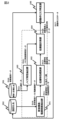
- FIG. 1 is a diagram showing the overall configuration of a computer system according to a first embodiment.
- the computer system includes a processor 1, a storage section 2, an input section 3, an output section 4, and a connection line 5 connecting these.
- the processor 1 is, for example, a CPU as described above.
- the storage unit 2 is a memory, an HDD (Hard Disk Drive), or the like.
- the input unit 3 is a keyboard, a mouse, a touch panel, etc.
- the output unit 4 is, for example, a display.
- the connection line 5 is a wiring on a circuit board, a connection cord, a network, or the like. These configurations do not need to be located at the same location, and may be installed at remote locations and connected via a network or the like.
- the processor 1 executes each function by reading and executing a program stored in the storage unit 2 or the like.
- each function executed by the processor 1 is conceptually explained as a housing structure/wire route extraction section 101, a propagation characteristic estimation section 102, a noise characteristic extraction section 103, a propagation amount calculation section 104, and a malfunction risk determination section 105. It is shown as Details of each part will be described later.
- the storage unit 2 has an analysis/measurement database 201 and a design database 202.
- the analysis/measurement database 201 stores damaged device data (D16) and noise source data (D13). Damaged devices are assumed to be ECUs and various antennas, and noise sources are assumed to be inverters and various sensors.
- the damaged device data (D16) corresponds to, for example, data regarding vulnerability obtained through device testing and data regarding the importance of the device.
- Vulnerability data is data on how much noise at a predetermined frequency in a victim device requires to cause a malfunction, and includes information such as reception sensitivity frequency characteristics and multiple thresholds (voltage thresholds and probability thresholds described later). is included. Data regarding the importance of devices is data that indicates the degree of risk influence of each device within the housing. is set higher than.
- the noise source data (D13) is data related to noise emitted by the noise source, and is obtained in advance by analysis or actual measurement. Note that the noise included in the acquired data may be radiation noise or conduction noise.
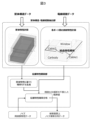
- FIG. 2 is a diagram showing the overall flow of electromagnetic noise analysis in Example 1
- FIG. 3 is a diagram showing a specific calculation flow in the broken line portion of FIG. 2.
- the housing structure/wire route extraction unit 101 acquires housing structure data and wire route data (D10) from the design database 202. , calculate the housing characteristics and the propagation characteristics (coupling characteristics of the wire paths) between each port.
- the housing characteristics are characteristics obtained by calculation by the housing structure/wire route extraction unit 101 based on the housing structure data acquired from the design database 202, and include the volume of the housing (vehicle body), Q value, etc. is included.
- the propagation characteristics between each port are determined by the case structure/wire route extraction unit 101 based on the wire route data acquired from the design database 202. This characteristic can be obtained by individually calculating the effect of each port on the victim device, which is another port. In this calculation, only the neighboring region that affects the radiation characteristics of each port needs to be modeled, so the calculation cost can be reduced.
- FIG. 4 is a diagram showing an example of data of a propagation characteristic probability distribution between a noise source and a victim device, in which the x-axis represents frequency, the y-axis represents propagation characteristics, and the z-axis represents probability distribution.
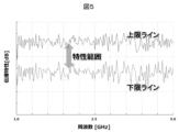
- FIG. 5 is a graph when FIG. 4 is viewed from the z-axis direction, with the x-axis representing frequency and the y-axis representing propagation characteristics.
- the propagation characteristics that is, the ease with which noise is transmitted from the noise source to the victim device
- the probability distribution thereof also differs.
- the range of characteristics that occur with a certain probability or more cannot be ignored, so if the upper and lower limits of the propagation characteristics are determined in a form that corresponds to the range of characteristics, the upper and lower limit lines as shown in Figure 5 are created. can be drawn.
- the peaks of the probability distribution in FIG. 4 are connected for each frequency, a line of the mode can be drawn in FIG. 5.
- the noise characteristic extraction unit 103 acquires noise source data (D13) from the analysis/measurement database 201 and extracts the frequency characteristics of noise emitted by the noise source.
- the propagation amount calculation unit 104 separates the victim device from the noise source based on the propagation characteristic probability distribution data (D12) outputted by the propagation characteristic estimation unit 102 and the noise frequency characteristic data (D14) outputted by the noise characteristic extraction unit 103. Statistically estimate the amount of noise propagated to
- the malfunction risk determination unit 105 compares the malfunction occurrence probability with a predetermined threshold included in the damaged device data (D16), and determines that the risk is high if it is greater than or equal to the threshold, and the risk is small if it is less than the threshold. It's okay.
- the determination result by the malfunction risk determination unit 105 is output to the design database 202 as malfunction risk data (D17).
- the malfunction risk data (D17) is stored in the design database 202, and is fed back to the SIL (Safety Integrity Level) design as a failure rate as necessary to be utilized for updating the design data. Further, the malfunction risk data (D17) is displayed via the output unit 4 as "During XX operation, error occurs with probability of XX". In this way, if the risk is quantitatively expressed as the probability of malfunction occurring in the victim device, it will be useful for EMC design.
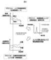
- FIG. 6 is a diagram showing an overall image of electromagnetic noise analysis in Example 2. This example differs from Example 1 in the following two points.
- the first difference is that the noise characteristic extraction unit 103 of this embodiment extracts a plurality of noise frequency characteristics for each operating state of the noise source.
- the noise source is an inverter of an electric vehicle
- the noise characteristic extraction unit 103 extracts the frequency characteristics of noise caused by switching of the inverter during acceleration operation, and the frequency characteristics of noise caused by switching of the inverter during regeneration (deceleration) operation. and are extracted separately.
- Graph 2A in FIG. 6 shows noise frequency characteristics in acceleration mode as control 1 and regeneration mode as control 2.
- the accuracy of the noise probability distribution on the victim device obtained by the propagation amount calculation unit 104 is improved, and as a result, the determination by the malfunction risk determination unit 105 is improved. Accuracy is also improved.
- the switching interval of the inverter is different between the low speed range and the high speed range, so it is desirable to use different noise frequency characteristic data for each speed range.
- the second difference is that the malfunction risk determination unit 105 of this embodiment does not calculate the probability of malfunction occurrence itself, but rather determines whether excessive noise (induced voltage) will occur and what the probability of that occurrence is. The point is to determine the magnitude of risk by comparing it with voltage thresholds and probability thresholds.
- step S202 if the probability distribution of the induced voltage exceeds the voltage threshold, the malfunction risk determination unit 105 determines whether the probability of generating such induced voltage noise is greater than a predetermined probability threshold (step S203). ). If the noise occurrence probability is greater than the probability threshold, the malfunction risk determination unit 105 determines that the risk is high, outputs it to the design database 202 (step S204), and ends the determination process.
- the malfunction risk determination unit 105 determines if the probability of occurrence is sufficiently low (does not exceed the probability threshold). , it is determined that the risk of the victim device malfunctioning is small. That is, in this embodiment, since the risk is determined by taking into account not only the intensity of noise but also the probability of its occurrence, highly accurate determination can be made and excessive EMC design can be avoided.
- the noise characteristic extraction unit 103 extracts not only the frequency characteristic of noise but also the probability of occurrence of each noise
- the propagation amount calculation unit 104 extracts not only the frequency characteristic of noise but also the probability of occurrence of each noise. This is different from the second embodiment in that the amount of noise propagation is roughly estimated using the following method. As in this embodiment, when the probability of occurrence of noise in the noise source is also considered, the accuracy of the noise probability distribution on the victim device obtained by the propagation amount calculation unit 104 is improved, and as a result, the accuracy of the determination by the malfunction risk determination unit 105 is also improved. improves.
- the housing structure/wire route extraction unit 101 extracts housing characteristic data and radiation characteristic data (D11) between each port, and the noise characteristic extraction unit 103 extracts noise frequency characteristic data (D14). ), but if D11 and D14 are stored in the design database 202 and the analysis/measurement database 201 in advance, the casing structure/wire route extraction section 101 and the noise characteristic extraction section 103 can be omitted. Further, in each of the above embodiments, the noise source data (D13) and the victim device data (D16) are stored in the common analysis/measurement database 201, but each data may be stored in separate databases. .
Landscapes
- Engineering & Computer Science (AREA)
- Physics & Mathematics (AREA)
- Theoretical Computer Science (AREA)
- Computer Hardware Design (AREA)
- Evolutionary Computation (AREA)
- Geometry (AREA)
- General Engineering & Computer Science (AREA)
- General Physics & Mathematics (AREA)
- Computer Networks & Wireless Communication (AREA)
- Testing Electric Properties And Detecting Electric Faults (AREA)
Abstract
Description
解析・計測データベース201は、被害装置データ(D16)およびノイズ源データ(D13)を格納する。被害装置としては、ECUや各種アンテナなどが想定され、ノイズ源としては、インバータや各種センサなどが想定される。被害装置データ(D16)は、例えば、装置の試験を通じて得られる脆弱性に関するデータ、装置の重要度に関するデータが該当する。脆弱性に関するデータは、被害装置において所定の周波数でどれだけの強度のノイズがあると誤動作が発生するかに関するデータであり、受信感度周波数特性や、複数の閾値(後述の電圧閾値や確率閾値)が含まれる。装置の重要度に関するデータは、筐体内の装置ごとのリスクの影響度合いを示すデータであり、車両の場合、例えば、車両の動作を制御する装置の重要度が、カーオーディオ関連の装置の重要度よりも高く設定される。ノイズ源データ(D13)は、ノイズ源が発するノイズに関するデータであり、解析や実測によって予め取得される。なお、取得されるデータに含まれるノイズは、放射ノイズであっても、伝導ノイズであっても良い。
この伝播特性確率分布は、精緻な3D解析を行わなくても、概算値として得ることができるので、解析時間の短縮につながる。
図7に示すように、本実施例の誤動作リスク判定部105は、まず、伝播量計算部104から被害装置上ノイズ確率分布データ(D15)として、被害装置上の誘起電圧の確率分布(図6のグラフ2C)を取得する(ステップS201)。次に、誤動作リスク判定部105は、被害装置上の誘起電圧の確率分布が所定の電圧閾値を超えるか否かを判定する(ステップS202)。
Claims (14)
- 筐体構造および電線経路の情報に基づき、筐体内部の電磁界特性を統計的に概算して伝播特性確率分布データを出力する伝播特性概算部と、
ノイズ源が発するノイズの周波数特性と前記伝播特性確率分布データに基づき、前記ノイズ源から被害装置へのノイズ伝播量を統計的に概算して被害装置上ノイズ確率分布データを出力する伝播量計算部と、
前記被害装置上ノイズ確率分布データに基づき、前記被害装置の誤動作リスクを判定する誤動作リスク判定部と、
を備えた電磁ノイズ解析装置。 - 請求項1において、
前記伝播量計算部は、前記ノイズ源の動作状態ごとの複数の周波数特性を用いて、前記ノイズ伝播量を概算する電磁ノイズ解析装置。 - 請求項1において、
前記伝播量計算部は、ノイズの周波数特性だけでなく、ノイズの発生確率も用いて、前記ノイズ伝播量を概算する電磁ノイズ解析装置。 - 請求項1において、
前記誤動作リスク判定部は、前記被害装置の脆弱性に関するデータも用いて、前記被害装置の誤動作リスクを判定する電磁ノイズ解析装置。 - 請求項4において、
前記誤動作リスク判定部は、前記被害装置の脆弱性に関するデータと前記被害装置上ノイズ確率分布データとを用いた演算の結果に基づいて、前記被害装置の誤動作発生確率を出力する電磁ノイズ解析装置。 - 請求項4において、
前記被害装置の脆弱性に関するデータには、ノイズ電圧の大きさに関する電圧閾値と、ノイズの発生確率に関する確率閾値と、が含まれ、
前記誤動作リスク判定部は、前記被害装置上ノイズ確率分布データを、前記電圧閾値および前記確率閾値と比較することで、リスクの大小を出力する電磁ノイズ解析装置。 - 請求項1において、
ノイズの周波数特性をディファレンシャルモードからコモンモードに変換して前記伝播量計算部に出力するノイズ特性抽出部を、さらに備える電磁ノイズ解析装置。 - 請求項7において、
前記伝播量計算部は、前記ノイズ伝播量をコモンモードからディファレンシャルモードに変換し、前記被害装置上ノイズ確率分布データとして前記誤動作リスク判定部に出力する電磁ノイズ解析装置。 - 伝播特性概算部が、筐体構造および電線経路の情報に基づき、筐体内部の電磁界特性を統計的に概算して伝播特性確率分布データを出力するステップと、
伝播量計算部が、ノイズ源が発生するノイズの周波数特性と前記伝播特性確率分布データに基づき、前記ノイズ源から被害装置へのノイズ伝播量を統計的に概算して被害装置上ノイズ確率分布データを出力するステップと、
誤動作リスク判定部が、前記被害装置上ノイズ確率分布データに基づき、前記被害装置の誤動作リスクを判定するステップと、
を備えた電磁ノイズ解析方法。 - 請求項9において、
前記伝播量計算部は、前記ノイズ源の動作状態ごとの複数の周波数特性を用いて、前記ノイズ伝播量を概算する電磁ノイズ解析方法。 - 請求項9において、
前記伝播量計算部は、ノイズの周波数特性だけでなく、ノイズの発生確率も用いて、前記ノイズ伝播量を概算する電磁ノイズ解析方法。 - 請求項9において、
前記誤動作リスク判定部は、前記被害装置の脆弱性に関するデータも用いて、前記被害装置の誤動作リスクを判定する電磁ノイズ解析方法。 - 請求項9において、
ノイズ特性抽出部が、ノイズの周波数特性をディファレンシャルモードからコモンモードに変換するステップを、さらに備える電磁ノイズ解析方法。 - 請求項13において、
前記伝播量計算部は、前記被害装置上ノイズ確率分布データをコモンモードからディファレンシャルモードに変換して出力する電磁ノイズ解析方法。
Priority Applications (1)
| Application Number | Priority Date | Filing Date | Title |
|---|---|---|---|
| US18/866,102 US20250322137A1 (en) | 2022-06-16 | 2023-04-05 | Electromagnetic Noise Analysis Device and Electromagnetic Noise Analysis Method |
Applications Claiming Priority (2)
| Application Number | Priority Date | Filing Date | Title |
|---|---|---|---|
| JP2022-096932 | 2022-06-16 | ||
| JP2022096932A JP7853844B2 (ja) | 2022-06-16 | 2022-06-16 | 電磁ノイズ解析装置および電磁ノイズ解析方法 |
Publications (1)
| Publication Number | Publication Date |
|---|---|
| WO2023243191A1 true WO2023243191A1 (ja) | 2023-12-21 |
Family
ID=89192729
Family Applications (1)
| Application Number | Title | Priority Date | Filing Date |
|---|---|---|---|
| PCT/JP2023/014092 Ceased WO2023243191A1 (ja) | 2022-06-16 | 2023-04-05 | 電磁ノイズ解析装置および電磁ノイズ解析方法 |
Country Status (3)
| Country | Link |
|---|---|
| US (1) | US20250322137A1 (ja) |
| JP (1) | JP7853844B2 (ja) |
| WO (1) | WO2023243191A1 (ja) |
Citations (3)
| Publication number | Priority date | Publication date | Assignee | Title |
|---|---|---|---|---|
| EP0982594A1 (en) * | 1998-08-24 | 2000-03-01 | BRITISH TELECOMMUNICATIONS public limited company | Method and apparatus for electromagnetic emissions testing |
| JP2010146096A (ja) * | 2008-12-16 | 2010-07-01 | Oki Electric Ind Co Ltd | 電磁界シミュレータ |
| JP2013186683A (ja) * | 2012-03-08 | 2013-09-19 | Hitachi Ltd | 電磁ノイズ解析方法及び装置 |
-
2022
- 2022-06-16 JP JP2022096932A patent/JP7853844B2/ja active Active
-
2023
- 2023-04-05 WO PCT/JP2023/014092 patent/WO2023243191A1/ja not_active Ceased
- 2023-04-05 US US18/866,102 patent/US20250322137A1/en active Pending
Patent Citations (3)
| Publication number | Priority date | Publication date | Assignee | Title |
|---|---|---|---|---|
| EP0982594A1 (en) * | 1998-08-24 | 2000-03-01 | BRITISH TELECOMMUNICATIONS public limited company | Method and apparatus for electromagnetic emissions testing |
| JP2010146096A (ja) * | 2008-12-16 | 2010-07-01 | Oki Electric Ind Co Ltd | 電磁界シミュレータ |
| JP2013186683A (ja) * | 2012-03-08 | 2013-09-19 | Hitachi Ltd | 電磁ノイズ解析方法及び装置 |
Also Published As
| Publication number | Publication date |
|---|---|
| US20250322137A1 (en) | 2025-10-16 |
| JP7853844B2 (ja) | 2026-04-30 |
| JP2023183428A (ja) | 2023-12-28 |
Similar Documents
| Publication | Publication Date | Title |
|---|---|---|
| US8201122B2 (en) | Computing resistance sensitivities with respect to geometric parameters of conductors with arbitrary shapes | |
| CN109074519B (zh) | 信息处理装置、信息处理方法以及程序 | |
| CN111976623A (zh) | 面向智能汽车的底盘域控制器、车辆的控制方法及车辆 | |
| CN113792438B (zh) | 一种整车电磁抗干扰性能评估方法及装置 | |
| US20140081609A1 (en) | Method of simulation of unsteady aerodynamic loads on an external aircraft structure | |
| CN113052892A (zh) | 一种车辆货物体积计算方法、装置及存储介质 | |
| CN116540073A (zh) | 车规级芯片的安全分析方法、装置、设备及存储介质 | |
| Ramezani et al. | Multiple objective functions for falsification of cyber-physical systems | |
| CN117290944A (zh) | 电气模块的布置方法、装置、设备、车辆底盘及车辆 | |
| WO2023243191A1 (ja) | 電磁ノイズ解析装置および電磁ノイズ解析方法 | |
| CN117970029A (zh) | 基于多模态行波传输的电力电缆故障诊断方法及系统 | |
| CN113379852A (zh) | 用于验证相机标定结果的方法、装置、电子设备和介质 | |
| CN120124400B (zh) | 一种抗干扰电子线束的加工方法 | |
| Parmantier et al. | Electromagnetic coupling on complex systems: Topological approach | |
| US8381149B2 (en) | Timing analysis apparatus, timing analysis method, and timing analysis program | |
| US9317649B2 (en) | System and method of determining high speed resonance due to coupling from broadside layers | |
| US7398424B2 (en) | False path detection program | |
| WO2024011510A1 (zh) | 基于模型降阶边界元法的声压评估方法、装置及终端设备 | |
| Beetner et al. | Validation of worst-case and statistical models for an automotive EMC expert system | |
| CN120930269B (zh) | 整车到零部件的人体电磁防护性能目标分解方法及装置 | |
| CN117215908A (zh) | 用于执行数据处理的方法 | |
| US20180076911A1 (en) | Signal line noise resistance evaluating method and its device | |
| CN118235131A (zh) | 构建车辆动力学模型的方法、装置、设备和存储介质 | |
| Dhar et al. | Prediction of radiated emission with transmission line model for CISPR 25 | |
| Lu et al. | SoC-level safety-oriented design process in electronic system level development environment |
Legal Events
| Date | Code | Title | Description |
|---|---|---|---|
| 121 | Ep: the epo has been informed by wipo that ep was designated in this application |
Ref document number: 23823495 Country of ref document: EP Kind code of ref document: A1 |
|
| WWE | Wipo information: entry into national phase |
Ref document number: 18866102 Country of ref document: US |
|
| NENP | Non-entry into the national phase |
Ref country code: DE |
|
| 122 | Ep: pct application non-entry in european phase |
Ref document number: 23823495 Country of ref document: EP Kind code of ref document: A1 |
|
| WWP | Wipo information: published in national office |
Ref document number: 18866102 Country of ref document: US |