WO2023243103A1 - 判定装置、判定方法、及びプログラム - Google Patents
判定装置、判定方法、及びプログラム Download PDFInfo
- Publication number
- WO2023243103A1 WO2023243103A1 PCT/JP2022/024425 JP2022024425W WO2023243103A1 WO 2023243103 A1 WO2023243103 A1 WO 2023243103A1 JP 2022024425 W JP2022024425 W JP 2022024425W WO 2023243103 A1 WO2023243103 A1 WO 2023243103A1
- Authority
- WO
- WIPO (PCT)
- Prior art keywords
- trace
- probability
- model
- traces
- context
- Prior art date
- Legal status (The legal status is an assumption and is not a legal conclusion. Google has not performed a legal analysis and makes no representation as to the accuracy of the status listed.)
- Ceased
Links
Images








Classifications
-
- G—PHYSICS
- G06—COMPUTING OR CALCULATING; COUNTING
- G06Q—INFORMATION AND COMMUNICATION TECHNOLOGY [ICT] SPECIALLY ADAPTED FOR ADMINISTRATIVE, COMMERCIAL, FINANCIAL, MANAGERIAL OR SUPERVISORY PURPOSES; SYSTEMS OR METHODS SPECIALLY ADAPTED FOR ADMINISTRATIVE, COMMERCIAL, FINANCIAL, MANAGERIAL OR SUPERVISORY PURPOSES, NOT OTHERWISE PROVIDED FOR
- G06Q10/00—Administration; Management
- G06Q10/06—Resources, workflows, human or project management; Enterprise or organisation planning; Enterprise or organisation modelling
Definitions
- the present disclosure relates to process mining, and in particular, to trace deviation determination.
- Process mining is a general term for technology that performs analysis using two things: a process model that represents a business process, and an event log that is a history of business execution.
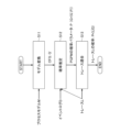
- a process model is a graph that defines the activities to be executed in a certain business process and the order of those activities, as shown in Figure 1.
- the event log is a log that records activities performed by the user.
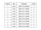
- Each record (event) in the event log has as required items a case ID representing one task, a timestamp representing the time of execution, and an event representing the content of the performed work.
- an event may have additional items such as the user who executed the task and other additional information (such as a document used in the task).
- additional items such as the user who executed the task and other additional information (such as a document used in the task).
- data with the same Case ID is arranged by timestamp, and a collection of traces that lists only events is ⁇ a,b,d,c,e,g> 10 , It is expressed as a set (multiset) with the number of occurrences of the sequence, such as ⁇ a,g,b,e> 5 ,... ⁇ .
- conformance checking is one of the tasks of process mining, and is a task of checking whether each trace in the event log does not deviate from the business process specified in the process model.
- DX digital transformation
- Non-Patent Documents 1 to 3 there is an alignment method that verifies whether each trace corresponds to an activity in the model (whether alignment can be obtained) (see Non-Patent Documents 1 to 3). Furthermore, the approach of reproducing traces on a model using tokens (see Non-Patent Document 4) is faster than the techniques of Non-Patent Documents 1 to 3.
- Non-Patent Documents 1 to 3 require a lot of time. Furthermore, the conventional approach (see Non-Patent Document 4) does not operate accurately if activities overlap on one model.
- the present invention was developed in view of the above-mentioned problems, and an object of the present invention is to perform trace deviation determination faster than conventional methods.
- the invention according to claim 1 provides a determination device for determining a trace that deviates from a business process defined by a process model in process mining, the determination device calculating a probability based on the inputted process model.
- a model conversion unit that converts the context-free grammar into a context-free grammar that is a possible data format; and a probability that estimates a probability parameter of the context-free grammar based on the context-free grammar converted by the model conversion unit and the set of traces.
- trace deviation determination can be performed faster than before.
- FIG. 3 is a diagram showing an example of a process model.
- FIG. 3 is a diagram showing an event log.
- FIG. 7 is a diagram illustrating an example of a probability display screen for providing a trace probability estimation result to a user.
- FIG. 2 is an electrical hardware configuration diagram of a determination device according to an embodiment.
- FIG. 1 is a functional configuration diagram of a determination device according to an embodiment.
- FIG. 2 is a diagram of an operation sequence showing a process or operation performed by the determination device.
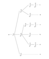
- 2 is a diagram showing an example of a process tree equivalent to the business process of FIG. 1; FIG. It is a table explaining each operator in a process tree.
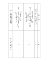
- FIG. 3 is a diagram showing definitions of each operation on a node.
- FIG. 1 is a functional configuration diagram of a determination device according to an embodiment.
- FIG. 2 is a diagram of an operation sequence showing a process or operation performed by the determination device.
- 2 is a diagram showing an example of a process tree equivalent to
- FIG. 6 is a diagram showing how a trace ⁇ a,b,d,c,g,f> is generated from a process tree.
- 11 is a table representing the trace tree of FIG. 10 using generation rules.
- FIG. 3 is a diagram showing a set of four elements of a context-free grammar.
- FIG. 6 is a diagram showing a conversion method into generation rules for each operator.
- FIG. 3 is a diagram showing a process tree with a PARALLEL operator.
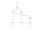
- FIG. 3 is a diagram showing an example of a trace tree with discontinuity.
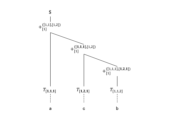
- FIG. 3 is a diagram showing an example of a trace tree with a PARALLEL operator without discontinuity.
- FIG. 2 is a diagram illustrating the concept of states and transitions in the proposed method of this embodiment.
- FIG. 7 is a diagram showing the definition of transition for each operator.
- FIG. 1 is a diagram showing an example of a process model.
- FIG. 2 is a diagram showing an event log.
- FIG. 3 is a diagram showing an example of a probability display screen for providing the user with the estimated trace probability.
- the determination device 3 normally displays only a predetermined trace (first trace) whose appearance probability is less than a threshold value (for example, 0.01) among each trace in the set of traces, and The trace (second trace) for which is greater than or equal to the threshold value is displayed in black and white inverted. That is, the display format differs depending on whether the appearance probability is less than the threshold value. Note that instead of the black and white inverted display, the display may be grayed out, or may not be displayed at all.
- the trace ⁇ b,d,a> of Case ID:2 has a probability of 0 to appear from the process model of FIG. 1, so it is filtered out as a deviation.
- a probability of 0 means that the trace cannot appear no matter how you run the model. In other words, it indicates that the execution of the task does not follow the prescribed process.
- the trace ⁇ a,b,d,b,d,c,g,f> of Case ID:3 can appear from the process model in FIG. 1, so the probability is not 0. However, since this is a somewhat rare case where multiple repetitions are performed, the probability decreases, and this is also extracted as an aberration.
- the trace of Case ID:3 can be generated from the model at a low frequency, so it is difficult to consider it as a deviation using conventional conformance checking methods.
- "suitable but abnormal behavior" can be found.
- Case ID:3 can be considered normal if it is repeated to this extent by adjusting the filter value. Furthermore, the determination device 3 actually estimates the "probability that the activity will be repeatedly executed" from the event log when estimating the probability parameter. Therefore, if the activity is repeated frequently in the actual data, the probability that the trace of Case ID:3 will appear will increase and it will be difficult to judge it as a deviation. In this manner, the determination device 3 of the present embodiment can extract traces with a low possibility of appearance, that is, history of business execution that is abnormal when compared with actual business logs, from a large amount of business logs.
- FIG. 4 is an electrical hardware configuration diagram of the determination device according to the embodiment.
- the determination device 3 is configured by one or more computers.
- the determination device 3 When the determination device 3 is constituted by a plurality of computers, it may be referred to as a "determination device” or a "determination system.”
- the determination device 3 is a computer that includes a CPU (Central Processing Unit) 301, a ROM (Read Only Memory) 302, a RAM (Random Access Memory) 303, an SSD (Solid State Drive) 304, It includes an external device connection I/F (Interface) 305, a network I/F 306, a media I/F 309, and a bus line 310.
- a CPU Central Processing Unit
- ROM Read Only Memory
- RAM Random Access Memory
- SSD Solid State Drive
- the CPU 301 controls the operation of the entire determination device 3.
- the ROM 302 stores programs used to drive the CPU 301, such as IPL (Initial Program Loader).
- RAM 303 is used as a work area for CPU 301.
- the SSD 304 reads or writes various data under the control of the CPU 301.
- an HDD Hard Disk Drive
- an HDD Hard Disk Drive
- the external device connection I/F 305 is an interface for connecting various external devices.
- External devices in this case include a display, speaker, keyboard, mouse, USB (Universal Serial Bus) memory, printer, and the like.
- the network I/F 306 is an interface for data communication via the communication network 100.
- the media I/F 309 controls reading or writing (storage) of data to a recording medium 309m such as a flash memory.
- the recording media 309m also include DVDs (Digital Versatile Discs), Blu-ray Discs (registered trademark), and the like.
- the bus line 310 is an address bus, a data bus, etc. for electrically connecting each component such as the CPU 301 shown in FIG. 4.
- FIG. 5 is a functional configuration diagram of the determination device according to the embodiment.
- the determination device 3 includes a probability model acquisition section 31 and a trace conformity confirmation section 32. Further, the probability model acquisition section 31 includes a model conversion section 311 and a probability estimation section 312.
- the model conversion unit 311 of the probability model acquisition unit 31 converts the input process model into a context free grammar (CFG), which is a data format in which probabilities can be calculated.
- CFG context free grammar
- the probability estimation unit 312 of the probability model acquisition unit 31 estimates the probability parameters of the CFG based on the CFG and the set of traces.
- the trace conformity confirmation unit 32 calculates the probability of appearance of each trace in the process model for each trace in the set of traces given as input, based on the probability parameters estimated by the probability estimation unit 312, and displays the probability of occurrence on the output screen. etc. to output the probability of occurrence.
- the set of traces given to the input may be the same as or different from the input of the probabilistic model acquisition unit 31.
- the output screen for the user displays the given traces and the probabilities of each trace. This screen can display traces that are less than a given threshold parameter in a predetermined display format (for example, black and white inverted display) using a trace search function.
- FIG. 6 is a diagram of an operation sequence showing processes or operations performed by the determination device.
- the model conversion unit 311 executes model conversion once for a predetermined process model, and converts the process model into an internally computable format (CFG). In this state, the model conversion unit 311 holds the process model, but has not yet calculated the probability parameters.
- CFG internally computable format
- the probability estimation unit 312 estimates probability parameters in the process model using the event log as input.
- the probability parameter is estimated so that the frequency of appearance of a trace when the process model is executed matches the frequency of the trace given as input as much as possible.
- the trace conformity confirmation unit 32 receives the traces (or a set of traces) as input and outputs the probability on the model for each trace.
- the model conversion unit 311 only needs to execute it once the first time a process model is input, and the probability estimation unit 312 only needs to execute it once the first time an event log is input. Further, the trace conformity confirmation unit 32 executes auditing and the like whenever necessary. However, it is also possible for the probability estimation section 312 to execute the trace given to the trace conformity confirmation section 32 again as an additional input and update the parameters. By doing this, the parameters are adjusted each time data is added, making it possible to determine trace suitability with higher accuracy.
- the trace can be expressed as a series of events.
- represents the length of the trace (e.g.,
- 4).
- a given event log is considered to be a multiplex set of traces, and other information is ignored.
- a process model is a graph showing user activities and their order relationships. Generally, it is often expressed in BPMN as shown in FIG. 1, but in this embodiment, a business process expressed in a process tree is input.
- a process tree is an ordered tree that represents the dependencies of operators.
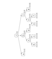
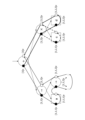
- FIG. 7 illustrates a process tree equivalent to the business process of FIG. 1.
- a process tree has a set N of leaf nodes corresponding to activities that generate observed events, and a set V of node nodes that express connection relationships between child nodes using operators. Any node other than the root node has one and only one node node as its parent node. Furthermore, since the process tree is an ordered tree, nodes having the same parent node have an ordering relationship. In FIG. 7, nodes with lower order are placed on the left.
- nodes in the process tree are identified by addresses.
- the address indicates the order of each node from the root node to that node.
- FIG. 7 shows the addresses of each node.
- the leaf node of event d is the root node ( ⁇ ), the second child node
- the address of the node for event d is [1,2,2].
- a node node in the process tree has a corresponding operator.
- Operators indicate relationships between child nodes. In this embodiment, four operators are used: SEQUENCE, SELECTION, PARALLEL, and LOOP. each operator. The symbols and relationships shown in FIG. 8 are represented.
- a leaf node of the process tree has a mapping l(v) to some event.
- FIG. 9 shows definitions of some operations on nodes.
- the model conversion unit 311 converts and holds a process tree representing trace generation conditions into a set of conversion processes from symbols to symbol strings called production rules called context-free grammars (CFGs).
- CFGs context-free grammars
- FIG. 10 is a diagram showing how a trace ⁇ a,b,d,c,g,f> is generated from a process tree.
- SEQUENCE( ⁇ ) generates three activities according to the process tree: an activity that generates a, a LOOP operator, and a PARALLEL operator. Additionally, the LOOP operator recursively generates repeating activities.
- a graph representing the process of generating such a trace is called a trace tree.
- trace trees are different from process trees. While one process tree is defined for each model, a trace tree is defined for each trace. Furthermore, since the trace tree represents the actual execution of the process model, the SELECTION operator takes only one value, and the LOOP operator appears as many times as the number of repetitions.
- a trace tree can be represented by a set of conversions A ⁇ from a certain symbol A to another symbol string ⁇ , called production rules.
- FIG. 11 shows the trace tree of FIG. 10 using generation rules. Starting from the starting symbol $, the trace can be finally obtained by repeating symbol conversion multiple times using production rules.
- CFG context-free grammar
- a trace is treated as a sentence, and the CFG is used to express the subprocess structure in the trace.
- the context-free grammar is represented by a set of four elements shown in FIG.
- a process tree can be converted to an equivalent CFG.
- the set E of events in the process tree is equal to the set E of terminal symbols.
- Node nodes in the process tree correspond to nonterminal symbols represented by operators.
- the generation rule corresponds to the relationship between child nodes defined for each operator. For example, the generation rule in Figure 11
- the SEQUENCE operator has three child nodes
- PCFG probabilistic context-free grammars
- model G the trace tree of trace L, that is, the sequence of production rules until L is generated, is
- a non-terminal symbol corresponds to each node of the process tree.
- generation rules depend only on the operator and child nodes of that node, with the exception of the PARALLEL operator. For example, for a node with a SEQUENCE operator, the production rule converts the nonterminal symbol representing the operator to the nonterminal symbol representing the child node.
- FIG. 13 shows the generation rules corresponding to each operator. Note that the production rule obtained by the proposed method is converted into an equivalent production rule so that three or more symbols do not exist on the right side. for example,
- a node with a PARALLEL operator cannot determine the generation rule only from that node and its child nodes. This problem will be explained using the process tree shown in FIG. 14 and traces ⁇ a, c, b> that can be generated from the tree as an example.
- T [1,1,1] and T [1,1,2] are always adjacent as ⁇ ...,T [1,1,1] ,T [1,1,2] ,...> .
- ⁇ [1,2] must be inserted between T [1,1,1] and T [1,1,2] . If this is expressed graphically, the edges intersect with each other as shown in FIG. In linguistics, a grammatical structure in which edges intersect is called "discontinuity," and the transformation cannot be expressed using a normal CFG.
- the PARALLEL operator can be expressed as a generation rule without discontinuity if the state of the subprocess for each subtree is maintained.
- FIG. 16 shows the generation process of ⁇ a, c, b> excluding discontinuity under the PARALLEL operator.
- the "activity generated at each child node" is held in the superscript of the nonterminal symbol indicating the PARALLEL operator. For example, when a symbol T [1,1,1] is generated that generates a,
- St(v) is a set of states in descendant nodes of node v.
- two states ⁇ v s , v e ⁇ , “start” and “end”, are set for any node v in the subtree.
- St(v) is defined as follows.
- a transition is represented by a set (s, v, s') of a state s, a next state s', and a node v whose state changes.
- Tr(v) be the set of transitions in the subtree of node v.
- Tr(v) is defined recursively from the child node transition Tr(ch(v,i)).
- FIG. 17 illustrates the concept of states and transitions in the proposed method of this embodiment.
- the starting state of the parent node transitions to the starting state of the child node
- the ending state of the child node transitions to the ending state of the parent node.
- the start state transitions directly to the end state.
- the transition outputs the corresponding event l(v).
- the state of the parent node transitions hierarchically to the state of the child node. For example, in the SEQUENCE operator, the parent node's starting state transitions to the first child node's starting state. If each child node also has child nodes, transition to those grandchild nodes recursively. When all child nodes have been transitioned, the state transitions to the end state of the parent node.
- the LOOP operator also transitions the states of child nodes in order. However, the final child node transitions back to the starting state of the first child node. Only the end state of the first child node can transition to the end state of the parent node.
- the SELECTION operator can transition to the starting state of any child node. Further, the end state of any child node transitions to the end state of the parent node. These transitions correspond to state transitions in the process represented by each subtree.
- FIG. 18 shows the acquisition formula for the transition of each operator.
- PGPM is equivalent to PCFG
- algorithms commonly known for PCFG can be used to estimate probability parameters and infer trace trees.
- the Inside-Outside algorithm (see Reference 1) can be used to estimate the probability parameters.
- M, E, R, $ The event log D and parameters other than probability (M, E, R, $) are given as inputs to the Inside-Outside algorithm.
- the output of probability parameter estimation, including the inside-outside algorithm is the probability P(r) (r ⁇ R) of each generation rule.
- the Inside-Outside algorithm searches for a parameter P that maximizes the likelihood P(D
- the definition of the probability determined by each algorithm is slightly different, and the value changes especially when multiple trace trees are considered for a trace.
- the former CKY algorithm outputs the trace tree with the maximum probability (that is, the most plausible as a generated process) among possible trace trees and its probability.
- the Inside algorithm outputs the sum of probabilities of possible trace trees. Since both probabilities can be used to identify unnatural traces, it does not matter which one is used.
- the probability model acquisition unit 31 (model conversion unit 311 and probability estimation unit 312) obtains PGPM G by inputting the event log D and the process M, and calculates the probability P(L
- the determination device 3 of the present embodiment focuses on the low probability of occurrence.
- a model representing a business process and a business log considered as a multiple set of traces are given as input, and the probability of occurrence of each trace in the business process is output. This has the effect that trace deviation determination can be performed faster than in the past.
- the determination device 3 of this embodiment has a trace search function based on probability, and can output traces whose probability is lower than a specified value to the user as a "deviation trace.”
- the present invention is not limited to the above-described embodiments, and may have the following configuration or processing (operation).
- the determination device 3 can be realized by a computer and a program, but this program can also be recorded on a (non-temporary) recording medium or provided via the communication network 100.
- the number of CPUs 301 is not limited to a single CPU, and may be a plurality of CPUs.
- Determination device 31 Probability model acquisition section 32 Trace conformance confirmation section 311 Model conversion section 312 Probability estimation section
Landscapes
- Engineering & Computer Science (AREA)
- Business, Economics & Management (AREA)
- Human Resources & Organizations (AREA)
- Strategic Management (AREA)
- Economics (AREA)
- Entrepreneurship & Innovation (AREA)
- Educational Administration (AREA)
- Game Theory and Decision Science (AREA)
- Development Economics (AREA)
- Marketing (AREA)
- Operations Research (AREA)
- Quality & Reliability (AREA)
- Tourism & Hospitality (AREA)
- Physics & Mathematics (AREA)
- General Business, Economics & Management (AREA)
- General Physics & Mathematics (AREA)
- Theoretical Computer Science (AREA)
- Debugging And Monitoring (AREA)
Abstract
本開示は、プロセスマイニングにおけるプロセスモデルで規定された業務プロセスを逸脱したトレースを判定する処理を、従来よりも高速に行うことを目的とする。 そのため、本開示の判定装置は、入力された前記プロセスモデルを、確率を計算可能なデータ形式である文脈自由文法へと変換するモデル変換部と、前記モデル変換部によって変換された前記文脈自由文法と前記トレースの集合に基づいて、前記文脈自由文法の確率パラメータを推定する確率推定部と、前記確率推定部によって推定された前記トレースの集合に係る確率パラメータに基づき、前記トレースの集合の各トレースに対して、前記プロセスモデルにおける前記各トレースの出現確率を計算し、閾値未満の出現確率である所定のトレースを前記逸脱したトレースと判定するトレース適合確認部と、を有する。
Description
本開示は、プロセスマイニングに関し、特に、トレースの逸脱判定に関する。
近年、プロセスマイニングの実践の機会が増え、コンフォーマンスチェッキングは社会的な重要度を増している。プロセスマイニングとは、業務プロセスを表すプロセスモデルと、業務の実行履歴であるイベントログの2つを用いて分析を行う技術の総称である。一般にプロセスモデルとは、図1に示すように、ある業務プロセスにおける実行されるアクティビティとそれらのアクティビティの順序を定義したグラフである。イベントログは図2に示すように、ユーザが実行したアクティビティを記録したログである。イベントログの各レコード(イベント)は、必須の項目として一つの業務を表すcase ID、実施時刻を表すtimestamp、そして実施した作業内容を表すeventを持つ。また、イベントは付加的な項目として、作業を実行したユーザや、その他付加情報(作業時のドキュメントなど)を持つこともある。分析内容によるが、多くのプロセスマイニングにおいては、同じCase IDをもつデータをタイムスタンプで並べ、イベントのみを羅列したトレースの集まりとして、{<a,b,d,c,e,g>10,<a,g,b,e>5,…}のように、系列の出現回数つき集合(多重集合)で表す。
また、コンフォーマンスチェックとはプロセスマイニングのタスクの一つで、イベントログ内の各トレースが、プロセスモデルで規定された業務プロセスを逸脱していないかどうかを確かめるタスクである。近年のDX(デジタルトランスフォーメーション)の隆盛から、イベントログの記録が容易になった。そのため、企業がルールに則って業務を行っているかを監査する場合に、大量のイベントログを解析することが要求される。その結果として、監査人がコンフォーマンスチェッキングを実用する事例が増えている。
ところが、これまでのコンフォーマンスチェッキングでは、プロセスモデルがトレースを生成できるかどうかのみが検証され、プロセスモデルにおける「トレースの出現の珍しさ」は考慮されなかった。実際の監査において、滅多に実行されないトレースは、例えモデルに適合していても、異常な振る舞いとして発見されるべきである。例として、図1のビジネスプロセスを実行する場合を考える。このビジネスプロセスから生成されるトレースには複数のdが含まれ得る。もし幾つものdを含む<a,b,d,b,d,b,d,c,d,b,d,b,d,b,d,c,d,c,d,b,e,g>のようなトレースがあった場合、何らかの理由でリトライを繰り返す不審なトレースであると考えるべきかもしれない。ところが、これまでのコンフォーマンスチェッキングの手法では、業務プロセス上起こり得るトレースは全て適合するとみなされてしまう。
また、従来のコンフォーマンスチェッキングの手法は、計算速度と任意のプロセスへの適用性との両立における問題がある。そこで、コンフォーマンスチェックでは、トレースのひとつひとつがモデル中のアクティビティと対応するかどうか(アライメントが得られるか)を検証するアライメント手法がある(非特許文献1~3参照)。更に、トークンを用いてモデル上でトレースを再生するアプローチ(非特許文献4参照)は、非特許文献1~3の技術に比べて高速である。
Adriansyah, A., van Dongen B.F., van der Aalst W.M.P.: Conformance Checking using Cost-based Fitness Analysis. In 2011 ieee 15th International Enterprise Distributed Object Computing Conference, pp. 55--64. IEEE (2011)
van der Aalst, W.M.P.: Decomposing Petri nets for process mining: A generic approach. Distributed and Parallel Databases, 31(4), pp. 471--507. (2013)
Lee, W.L.J., Verbeek, H. M. W., Munoz-Gama, J., van der Aalst, W.M.P., Sepulveda, M.: Recomposing conformance: Closing the circle on decomposed alignment-based conformance checking in process mining. Information Sciences, 466, pp. 55--91. (2018)
Berti, A., van der Aalst, W.M.P.: Reviving Token-based Replay: Increasing Speed While Improving Diagnostics. In ATAED@ Petri Nets/ACSD, pp.87--103. (2019)
しかし、従来のアライメント手法(非特許文献1~3参照)は多くの時間を要する。また、従来のアプローチ(非特許文献4参照)は、ひとつのモデル上でアクティビティが重複していると正確に動作しない。
本発明は上記の課題を鑑みてなれたものであって、トレースの逸脱判定を従来よりも高速に行うことを目的とする。
上記課題を解決するため、請求項1に係る発明は、プロセスマイニングにおけるプロセスモデルで規定された業務プロセスを逸脱したトレースを判定する判定装置であって、入力された前記プロセスモデルを、確率を計算可能なデータ形式である文脈自由文法へと変換するモデル変換部と、前記モデル変換部によって変換された前記文脈自由文法と前記トレースの集合に基づいて、前記文脈自由文法の確率パラメータを推定する確率推定部と、前記確率推定部によって推定された前記トレースの集合に係る確率パラメータに基づき、前記トレースの集合の各トレースに対して、前記プロセスモデルにおける前記各トレースの出現確率を計算し、閾値未満の出現確率である所定のトレースを前記逸脱したトレースと判定するトレース適合確認部と、を有する判定装置である。
以上説明したように本発明によれば、プロセスモデルにおける各トレースの出現確率の低さに着目することで、トレースの逸脱判定を従来よりも高速に行うことができるという効果を奏する。
以下、図面に基づいて本発明の実施形態を説明する。
まず、図1乃至図6を用いて、本実施形態を説明する。
〔概要〕
まずは、図1乃至図3を用いて、本実施形態の概要を説明する。
図1は、プロセスモデルの例を示す図である。図2は、イベントログを示す図である。図3はトレースの確率の推定結果をユーザに提供するための確率表示の画面例を示す図である。
まずは、図1乃至図3を用いて、本実施形態の概要を説明する。
図1は、プロセスモデルの例を示す図である。図2は、イベントログを示す図である。図3はトレースの確率の推定結果をユーザに提供するための確率表示の画面例を示す図である。
図3の画面例では、トレースと、そのトレースの出現確率Pr(L|G)が表示される。また、出現確率に基づくトレースのフィルタ機能を実行することができる。この例の表示形態では、判定装置3は、トレースの集合の各トレースのうち、出現確率が閾値(例えば、0.01)未満である所定のトレース(第1のトレース)のみを通常表示し、出現確率が閾値以上であるトレース(第2のトレース)は白黒反転表示している。即ち、出現確率が閾値未満か否かにより、表示形態が異なる。なお、白黒反転表示ではなく、グレーアウト表示でもよく、又はそもそも表示しなくてもよい。
また、図3の画面例では、Case ID:2のトレース<b,d,a>は、図1のプロセスモデルから出現する確率が0のため、逸脱としてフィルタ抽出されている。確率が0であるとは、モデルをどう実行しても、そのトレースが出現し得ないことを意味する。つまり、その業務の実行が規定されたプロセスに従っていないことを表す。Case ID:3のトレース<a,b,d,b,d,c,g,f>は、図1のプロセスモデルから出現し得るため、確率は0ではない。しかし、複数の繰返しを実施する少し珍しい例であるため、確率が低下し、これも逸脱として抽出されている。
特に、Case ID:3のトレースは、モデルからは低頻度ながらも生成可能であるために従来のコンフォーマンスチェッキングの手法では逸脱とみなすことが難しい。これに対して、本実施形態では、「適合するが異常な振る舞い」を見つけ出すことができる。
なお、Case ID:3は、フィルタの値を調整することで、この程度の繰り返しであれば正常であるとみなすことも可能である。また、判定装置3は、実際には確率パラメータの推定の際に「アクティビティが繰り返し実行される確率」をイベントログから推定する。そのため、アクティビティの繰り返しが実データの中で頻繁に行われていれば、Case ID:3のトレースの出現確率は上昇し、逸脱と判定されにくくなる。このように、本実施形態の判定装置3は、出現可能性の低いトレース、即ち、実際の業務ログと比較すると異常である業務実行の履歴を多量の業務ログの中から抽出できる。
〔ハードウェア構成〕
次に、図4を用いて、判定装置3の電気的なハードウェア構成を説明する。図4は、実施形態に係る判定装置の電気的なハードウェア構成図である。判定装置3は、単数又は複数のコンピュータによって構成されている。判定装置3が複数のコンピュータによって構成されている場合には、「判定装置」と示しても良いし、「判定システム」と示しても良い。
次に、図4を用いて、判定装置3の電気的なハードウェア構成を説明する。図4は、実施形態に係る判定装置の電気的なハードウェア構成図である。判定装置3は、単数又は複数のコンピュータによって構成されている。判定装置3が複数のコンピュータによって構成されている場合には、「判定装置」と示しても良いし、「判定システム」と示しても良い。
判定装置3は、コンピュータとして、図4に示されているように、CPU(Central Processing Unit)301、ROM(Read Only Memory)302、RAM(Random Access Memory)303、SSD(Solid State Drive)304、外部機器接続I/F(Interface)305、ネットワークI/F306、メディアI/F309、及びバスライン310を備えている。
これらのうち、CPU301は、判定装置3全体の動作を制御する。ROM302は、IPL(Initial Program Loader)等のCPU301の駆動に用いられるプログラムを記憶する。RAM303は、CPU301のワークエリアとして使用される。
SSD304は、CPU301の制御に従って各種データの読み出し又は書き込みを行う。なお、SSD304の代わりに、HDD(Hard Disk Drive)を用いても良い。
外部機器接続I/F305は、各種の外部機器を接続するためのインターフェースである。この場合の外部機器は、ディスプレイ、スピーカ、キーボード、マウス、USB(Universal Serial Bus)メモリ、及びプリンタ等である。
ネットワークI/F306は、通信ネットワーク100を介してデータ通信をするためのインターフェースである。
メディアI/F309は、フラッシュメモリ等の記録メディア309mに対するデータの読み出し又は書き込み(記憶)を制御する。記録メディア309mには、DVD(Digital Versatile Disc)やBlu-ray Disc(登録商標)等も含まれる。
バスライン310は、図4に示されているCPU301等の各構成要素を電気的に接続するためのアドレスバスやデータバス等である。
〔実施形態の機能構成〕
次に、図5を用いて、判定装置3の機能構成について説明する。図5は、実施形態に係る判定装置の機能構成図である。
次に、図5を用いて、判定装置3の機能構成について説明する。図5は、実施形態に係る判定装置の機能構成図である。
図5に示すように、判定装置3は、確率モデル取得部31、及びトレース適合確認部32を有している。また、確率モデル取得部31は、モデル変換部311、及び確率推定部312を有している。
確率モデル取得部31のモデル変換部311は、入力のプロセスモデルを、確率を計算可能なデータ形式である文脈自由文法(CFG)へと変換する。
確率モデル取得部31の確率推定部312は、CFGとトレースの集合に基づいて、CFGの確率パラメータを推定する。
トレース適合確認部32は、確率推定部312によって推定された確率パラメータに基づき、入力に与えられたトレースの集合の各トレースに対して、プロセスモデルにおけるその各トレースの出現確率を計算し、出力画面等で出現確率を出力する。このとき入力に与えられるトレースの集合は確率モデル取得部31の入力と同じでも、異なっていてもよい。ユーザへの出力画面では、与えられたトレースと、各トレースの確率が表示される。この画面はトレースの検索機能により、与えられた閾値パラメータを下回る(未満の)トレースを所定の表示形態(例えば、白黒反転表示)で表示可能である。
〔判定装置の処理又は動作〕
続いて、図6を用いて、判定装置3の処理又は動作について説明する。図6は、判定装置が実行する処理又は動作を示す動作シーケンスの図である。
続いて、図6を用いて、判定装置3の処理又は動作について説明する。図6は、判定装置が実行する処理又は動作を示す動作シーケンスの図である。
S11:まず、モデル変換部311は、所定のプロセスモデルに対して、初回に1度、モデル変換を実行し、プロセスモデルを内部で計算可能な形式(CFG)へと変換する。この状態では、モデル変換部311は、プロセスモデルを保持しているが、確率パラメータはまだ計算していない。
S12:確率推定部312は、イベントログを入力として、プロセスモデルにおける確率パラメータを推測する。端的には、確率パラメータは、そのプロセスモデルを実行したときのトレースの出現頻度が、入力に与えられたトレースの頻度とできるだけ一致するように推定される。
S13:トレース適合確認部32は、トレース(又はその集合)を入力として、各トレースに対するモデル上での確率を出力する。
なお、実行ライフサイクルとしては、モデル変換部311がプロセスモデルを入力する初回に1度だけ実行し、また確率推定部312もイベントログを入力する初回に1度だけ実行すれば良い。また、トレース適合確認部32は、監査などの実施が必要なときに、その都度実行する。但し、トレース適合確認部32に与えられたトレースを、追加の入力として、確率推定部312が再度実行し、パラメータを更新することも可能である。これを行うことでデータ追加の度にパラメータが調整されるため、より高精度なトレース適合判定が可能となる。
〔詳細〕
続いて、図7乃至図18を用いて、本発明の実施形態を詳細に説明する。
続いて、図7乃至図18を用いて、本発明の実施形態を詳細に説明する。
<入出力の処理>
本実施形態では、イベントログDの発生確率がプロセスモデルGを用いて表せる必要がある。つまりP(D;G)を表す数理モデルGの定義を目指す。ただし、イベントログに含まれるトレースはそれぞれ独立であるため、実際には
本実施形態では、イベントログDの発生確率がプロセスモデルGを用いて表せる必要がある。つまりP(D;G)を表す数理モデルGの定義を目指す。ただし、イベントログに含まれるトレースはそれぞれ独立であるため、実際には

タスクの種別を表すイベントの集合をEとすると、トレースはイベントの系列として表せる。本実施形態では、トレースを括弧で括ってL=<a,b,c> (a,b,c∈ ε)のように表す。|L|はトレースの長さを表す(e.g., |<a,b,c,b>|=4)。
本実施形態では、与えられたイベントログを、トレースの多重集合であるとみなし、それ以外の情報は無視する。イベントログDにトレースLがm個含まれることを、上付きの添字を用いて{Lm}と表す。例えば、D={<a,b,d>100,<a,c,d>10}のように表せる。
プロセスモデルは、ユーザのアクティビティとその順序関係を示したグラフである。一般には図1に示すようなBPMNで表現されることが多いが、本実施形態ではプロセスツリーで表された業務プロセスを入力とする。プロセスツリーは、オペレータの依存関係を表した順序木である。図7に、図1のビジネスプロセスと等しいプロセスツリーを例示する。
プロセスツリーは、観測イベントを生成するアクティビティに対応する葉ノードの集合Nと、子ノード同士の接続関係をオペレータで表す節ノードの集合Vを持つ。根ノードを除く任意のノードは、いずれかのただひとつの節ノードを親ノードに持つ。また、プロセスツリーは順序木であるため、同一の親ノードを持つノード同士は順序関係を持つ。図7では、順序の小さいノードが左側に置かれている。
本実施形態では、プロセスツリーのノードをアドレスで識別する。アドレスは、根ノードからそのノードまでの各ノードの順序を示す。図7には各ノードのアドレスを示している。例えば、イベントdの葉ノードは、根ノード(→)、2番目の子ノード

プロセスツリーの節ノードは、対応するオペレータを持つ。オペレータは子ノード間の関係性を示す。本実施形態では、SEQUENCE、SELECTION、PARALLEL、LOOPの4つのオペレータを用いる。それぞれのオペレータは。図8に示す記号と関係性を表す。
プロセスツリーの葉ノードは、いずれかのイベントへのマッピングl(v)を持つ。ここで、


<モデル変換部の処理>
続いて、モデル変換部311の処理について説明する。
続いて、モデル変換部311の処理について説明する。
モデル変換部311は、トレースの生成条件を表すプロセスツリーを、文脈自由文法(CFG)という生成ルールと呼ばれる記号から記号列への変換処理の集合へと変換して保持する。ここでは図7で示したプロセスツリーが入力であるとし、またトレースとして<a,b,d,c,g,f>が与えられた場合を考える。
あるトレースが与えられたとき、そのトレースがプロセスツリーから生成される過程は、図10のように木構造で表現することができる。図10は、トレース<a,b,d,c,g,f>がプロセスツリーから生成される様子を示す図である。例えば、SEQUENCE(→)は、aを生成するアクティビティと、LOOPオペレータと、PARALLELオペレータの3つをプロセスツリーに従って生成する。また、LOOPオペレータは、アクティビティの繰り返しを再帰的に生成している。このようなトレースが生成される過程を表したグラフをトレースツリーと呼ぶとする。
トレースツリーはプロセスツリーとは異なるものであることに注意する。プロセスツリーが一つのモデルに対して一つ定義されるのに対し、トレースツリーは各トレースに対して定義される。また、トレースツリーはプロセスモデルの実際の実行を表すため、SELECTIONオペレータは、いずれか一つしか値を取らず、LOOPオペレータは繰り返しの回数だけ出現する。
トレースツリーは、生成ルールと呼ばれるある記号Aから別の記号列αへの変換A⇒αの集合で表すことができる。図11は、図10のトレースツリーを生成ルールによって表したものである。開始記号$から、複数回の生成ルールによる記号の変換を繰り返して、最終的にトレースを獲得できる。
図11に示すような記号から記号列への変換過程は、自然言語処理で用いられる文脈自由文法(CFG)を用いて数学的に表せる。CFGとは、文の文法構造を表現するための数理モデルである。本実施形態では、トレースを文と見立てて、CFGはトレース中のサブプロセス構造を表現するために用いる。形式的には、文脈自由文法は図12に示す4要素の組で表される。
プロセスツリーは等価なCFGに変換できる。プロセスツリーにおけるイベントの集合Eは、終端記号の集合Eと等しい。プロセスツリーにおける節ノードは、オペレータで表される非終端記号に対応する。また、生成ルールはオペレータごとに定義される子ノード間の関係性に対応する。例えば、図11の生成ルール


更に我々は、プロセスツリーから、トレースの生成確率を持つ確率的生成型プロセスモデル(PGPM)への拡張を提案する。この拡張は、CFGから確率的文脈自由文法(PCFG)への拡張の応用である。PCFGとは、CFGの定義に任意の生成規則A⇒α ∈Rが適用される確率P(A⇒ α)の集合Pを加えたものである。ここで、同一の非終端記号Aを左側に持つ生成規則の確率の合計値は1である。PGPMは、CFGに各生成規則の確率Pを加えて、G=(M,E,R,$,P)と定義される。
モデルGにおいて、トレースLのトレースツリー、即ちLを生成するまでの生成規則の列を


(各オペレータの生成ルールへの変換)
続いて、プロセスツリーからPGPMの内P以外の要素を得る手法を説明する。既に説明したように、非終端記号の集合Eはイベントの集合Eと一致する。また、開始記号は常に$である。よって、ここでは、プロセスツリーからMとRを得る方法を説明する。
続いて、プロセスツリーからPGPMの内P以外の要素を得る手法を説明する。既に説明したように、非終端記号の集合Eはイベントの集合Eと一致する。また、開始記号は常に$である。よって、ここでは、プロセスツリーからMとRを得る方法を説明する。
非終端記号はプロセスツリーの各節ノードに対応する。また生成ルールは、PARALLELオペレータを除いて、そのノードのオペレータと子ノードにのみ依存する。例えば、SEQUENCEオペレータを持つノードでは、生成ルールはオペレータを示す非終端記号から子ノードを表す非終端記号への変換

図13に、各オペレータに対応する生成規則を示す。なお、提案手法で得られた生成規則では、右辺に3つ以上のシンボルが存在しないように等価な生成ルールへと変換が行われている。例えば、




(PARALLELオペレータの確率モデルへの変換)
PARALLELオペレータを持つノードは、そのノードと子ノードだけで生成ルールを決定することができない。図14に示すプロセスツリーと、そのツリーから生成可能なトレースである<a,c,b>を例に、この問題を説明する。
PARALLELオペレータを持つノードは、そのノードと子ノードだけで生成ルールを決定することができない。図14に示すプロセスツリーと、そのツリーから生成可能なトレースである<a,c,b>を例に、この問題を説明する。
上述の手順(各オペレータの生成ルールへの変換)と似たように変換を行うと、このモデルのノード[1,1]のSEQUENCEオペレータは


PARALLELオペレータは、サブツリーごとのサブプロセスの状態を保持すれば、discontinuityのない生成ルールで表せる。図16に、PARALLELオペレータ下のdiscontinuityを除外した<a,c,b>の生成過程を示す。この生成ルールでは、PARALLELオペレータを示す非終端記号の上付き添字で、「各子ノードで生成したアクティビティ」が保持されている。例えば、aを生成する記号T[1,1,1]が生成されたとき、


discontinuityのない生成規則を得るためには、PARALLELオペレータの下でのノードの完了を表す"状態"と、状態間の"遷移"を求める必要がある。PARALLELオペレータでは、子ノードのサブツリー毎のノードがどこまでアクティビティを終えたかの進捗を保有する。そこで、サブツリーごとの状態を全て取得し、状態の組み合わせをPARALLELオペレータの状態とする。

提案手法では、サブツリー内の任意のノードvで、それぞれ"開始"と"終了"の2つの状態{vs,ve}を設定した。
PARALLELでない任意のノードvにおいて、St(v)は以下のように定義される。

ノードvのサブツリーでの遷移の集合をTr(v)とする。
アクティビティは一つだけ実行されるので、PARALLELオペレータにおいては組み合わされたサブツリーの状態の内どれか一つだけが次状態に遷移する。

図17に、本実施形態の提案手法での状態と遷移の考え方を例示した。任意のノードにおいて、親ノードの開始状態は子ノードの開始状態へと遷移し、子ノードの終了状態から親ノードの終了状態へと遷移する。ただし、ACITIVITYオペレータのノードでは、開始状態は終了状態へと直接に遷移する。この時、その遷移は対応するイベントl(v)を出力する。
ACTIVITY以外のオペレータでは、親ノードの状態は子ノードの状態へと階層的に遷移する。例えば、SEQUENCEオペレータでは、親ノードの開始状態は第一子ノードの開始状態へと遷移する。各子ノードも子ノードを持っているならば、再帰的にそれらの孫ノードへと遷移する。全ての子ノードを遷移し終えると、親ノードの終了状態へと遷移する。
同様に、LOOPオペレータも子ノードの状態を順番に遷移する。ただし、最終子ノードは第一子ノードの開始状態へと再び遷移する。第一子ノードの終了状態のみが、親ノードの終了状態へと遷移できる。
SELECTIONオペレータは、任意の子ノードの開始状態へと遷移できる。また、任意の子ノードの終了状態は、親ノードの終了状態へと遷移する。これらの遷移は、各サブツリーの表すプロセスでの状態遷移に対応する。各オペレータの遷移の取得式を図18に示す。
PARALLELオペレータのサブツリーでは、次の状態へと遷移するとき、ノードvのオペレータがアクティビティであれば、対応するイベントを出力する非終端記号を生成する。即ち、以下のような生成ルールを得る。


<確率推定部の処理>
PGPMはPCFGと等価であるため、確率パラメータの推定やトレースツリーの推論には、PCFGで一般的に知られているアルゴリズムが利用できる。例えば、Inside-Outsideアルゴリズム(参考文献1参照)が確率パラメータの推定に用いることができる。
<参考文献1>Jelinek, F., Lafferty D.J., Mercer L.R.: Basic Methods of Probabilistic Context Free Grammars. In Speech Recognition and Understanding, pp. 345--360. Springer, Berlin, Heidelberg (1992)
Inside-Outsideアルゴリズムの入力には、イベントログDと確率以外のパラメータ(M,E,R,$)が与えられる。Inside-Outsideアルゴリズムも含め、確率パラメータ推定の出力は各生成ルールの確率P(r)(r∈R)である。特にInside-Outsideアルゴリズムでは、観測値の尤度P(D|P)をできるだけ大きくするパラメータPが探索される。
PGPMはPCFGと等価であるため、確率パラメータの推定やトレースツリーの推論には、PCFGで一般的に知られているアルゴリズムが利用できる。例えば、Inside-Outsideアルゴリズム(参考文献1参照)が確率パラメータの推定に用いることができる。
<参考文献1>Jelinek, F., Lafferty D.J., Mercer L.R.: Basic Methods of Probabilistic Context Free Grammars. In Speech Recognition and Understanding, pp. 345--360. Springer, Berlin, Heidelberg (1992)
Inside-Outsideアルゴリズムの入力には、イベントログDと確率以外のパラメータ(M,E,R,$)が与えられる。Inside-Outsideアルゴリズムも含め、確率パラメータ推定の出力は各生成ルールの確率P(r)(r∈R)である。特にInside-Outsideアルゴリズムでは、観測値の尤度P(D|P)をできるだけ大きくするパラメータPが探索される。
<トレース適合確認部の処理>
トレースの適合判定は、入力としてトレースLとモデルGが与えられ、確率P(L|G)を出力する。確率の算出においても、既存のアルゴリズムを用いることができる。確率を算出するアルゴリズムとしては、Cocke-Kasami-Younger(CKY)アルゴリズムや、Insideアルゴリズムなどが挙げられ、どちらも用いることができる(参考文献1参照)。
トレースの適合判定は、入力としてトレースLとモデルGが与えられ、確率P(L|G)を出力する。確率の算出においても、既存のアルゴリズムを用いることができる。確率を算出するアルゴリズムとしては、Cocke-Kasami-Younger(CKY)アルゴリズムや、Insideアルゴリズムなどが挙げられ、どちらも用いることができる(参考文献1参照)。
ここで、それぞれのアルゴリズムで求められる確率は若干定義が異なり、特にトレースに対して複数のトレースツリーが考えられる場合に値が変わる。前者のCKYアルゴリズムは、考えられるトレースツリーの内、確率が最大の(即ち、生成された過程としてもっともらしい)トレースツリーとその確率を出力する。対して、Insideアルゴリズムでは、ありえるトレースツリーの確率の合計を出力する。どちらの確率も不自然なトレースの識別には利用可能であるため、どちらを用いても構わない。
以上より、本実施形態では、確率モデル取得部31(モデル変換部311と確率推定部312)が、イベントログDとプロセスMを入力にしてPGPM Gを求め、任意のトレースLに対する確率P(L|G)を出力する。そして、トレース適合確認部32が、この出力されたP(L|G)を用いて、通常では発生頻度の低い、異常なトレースを検出する。
以上により、判定装置の処理又は動作の説明が終了する。
〔実施形態の効果〕
以上説明したように本実施形態によれば、プロセスモデルに適合するが、通常は考えられない振る舞いをしたトレースを見つけ出すために、本実施形態の判定装置3は、出現確率の低さに着目することで、入力に業務プロセスを示すモデルとトレースの多重集合とみなした業務ログが与えられ、各トレースに対する業務プロセス上での出現確率を出力する。これより、トレースの逸脱判定を従来よりも高速に行うことができるという効果を奏する。
以上説明したように本実施形態によれば、プロセスモデルに適合するが、通常は考えられない振る舞いをしたトレースを見つけ出すために、本実施形態の判定装置3は、出現確率の低さに着目することで、入力に業務プロセスを示すモデルとトレースの多重集合とみなした業務ログが与えられ、各トレースに対する業務プロセス上での出現確率を出力する。これより、トレースの逸脱判定を従来よりも高速に行うことができるという効果を奏する。
また、本実施形態の判定装置3は確率に基づくトレースの検索機能を有し、確率が指定値を下回るトレースを"逸脱トレース"として、ユーザに出力することができる。
〔補足〕
本発明は上述の実施形態に限定されるものではなく、以下に示すような構成又は処理(動作)であってもよい。
(1)判定装置3はコンピュータとプログラムによっても実現できるが、このプログラムを(非一時的な)記録媒体に記録することも、通信ネットワーク100を介して提供することも可能である。
(2)CPU301は、単一だけでなく、複数であってもよい。
本発明は上述の実施形態に限定されるものではなく、以下に示すような構成又は処理(動作)であってもよい。
(1)判定装置3はコンピュータとプログラムによっても実現できるが、このプログラムを(非一時的な)記録媒体に記録することも、通信ネットワーク100を介して提供することも可能である。
(2)CPU301は、単一だけでなく、複数であってもよい。
3 判定装置
31 確率モデル取得部
32 トレース適合確認部
311 モデル変換部
312 確率推定部
31 確率モデル取得部
32 トレース適合確認部
311 モデル変換部
312 確率推定部
Claims (4)
- プロセスマイニングにおけるプロセスモデルで規定された業務プロセスを逸脱したトレースを判定する判定装置であって、
入力された前記プロセスモデルを、確率を計算可能なデータ形式である文脈自由文法へと変換するモデル変換部と、
前記モデル変換部によって変換された前記文脈自由文法と前記トレースの集合に基づいて、前記文脈自由文法の確率パラメータを推定する確率推定部と、
前記確率推定部によって推定された前記トレースの集合に係る確率パラメータに基づき、前記トレースの集合の各トレースに対して、前記プロセスモデルにおける前記各トレースの出現確率を計算し、閾値未満の出現確率である所定のトレースを前記逸脱したトレースと判定するトレース適合確認部と、
を有する判定装置。 - 前記トレース適合確認部は、出現確率に基づくトレースのフィルタ機能により、前記閾値未満の出現確率である前記所定のトレースとしての第1のトレースと前記閾値以上の出現確率である第2のトレースとの表示形態を異ならせた画面データを出力する、請求項1に記載の判定装置。
- プロセスマイニングにおけるプロセスモデルで規定された業務プロセスを逸脱したトレースを判定する判定装置が実行する判定方法であって、
前記判定装置は、
入力された前記プロセスモデルを、確率を計算可能なデータ形式である文脈自由文法へと変換するモデル変換処理と、
前記モデル変換処理によって変換された前記文脈自由文法と前記トレースの集合に基づいて、前記文脈自由文法の確率パラメータを推定する確率推定処理と、
前記確率推定処理によって推定された前記トレースの集合に係る確率パラメータに基づき、前記トレースの集合の各トレースに対して、前記プロセスモデルにおける前記各トレースの出現確率を計算し、閾値未満の出現確率である所定のトレースを前記逸脱したトレースと判定するトレース適合確認処理と、
を実行する判定方法。 - コンピュータに、請求項3に記載の方法を実行させるプログラム。
Priority Applications (2)
| Application Number | Priority Date | Filing Date | Title |
|---|---|---|---|
| PCT/JP2022/024425 WO2023243103A1 (ja) | 2022-06-17 | 2022-06-17 | 判定装置、判定方法、及びプログラム |
| JP2024528076A JP7677542B2 (ja) | 2022-06-17 | 2022-06-17 | 判定装置、判定方法、及びプログラム |
Applications Claiming Priority (1)
| Application Number | Priority Date | Filing Date | Title |
|---|---|---|---|
| PCT/JP2022/024425 WO2023243103A1 (ja) | 2022-06-17 | 2022-06-17 | 判定装置、判定方法、及びプログラム |
Publications (1)
| Publication Number | Publication Date |
|---|---|
| WO2023243103A1 true WO2023243103A1 (ja) | 2023-12-21 |
Family
ID=89192731
Family Applications (1)
| Application Number | Title | Priority Date | Filing Date |
|---|---|---|---|
| PCT/JP2022/024425 Ceased WO2023243103A1 (ja) | 2022-06-17 | 2022-06-17 | 判定装置、判定方法、及びプログラム |
Country Status (2)
| Country | Link |
|---|---|
| JP (1) | JP7677542B2 (ja) |
| WO (1) | WO2023243103A1 (ja) |
Citations (4)
| Publication number | Priority date | Publication date | Assignee | Title |
|---|---|---|---|---|
| US20130103441A1 (en) * | 2011-10-21 | 2013-04-25 | International Business Machines Corporation | Generating Predictions for Business Processes Whose Execution is Driven by Data |
| JP2016014959A (ja) * | 2014-07-01 | 2016-01-28 | 日本電気株式会社 | 情報処理装置、反例処理方法、及び、プログラム |
| JP2016149023A (ja) * | 2015-02-12 | 2016-08-18 | 富士通株式会社 | 情報管理装置、情報管理方法および情報管理プログラム |
| JP2017027412A (ja) * | 2015-07-23 | 2017-02-02 | 富士通株式会社 | 表示情報制御プログラム、方法、及び装置 |
-
2022
- 2022-06-17 WO PCT/JP2022/024425 patent/WO2023243103A1/ja not_active Ceased
- 2022-06-17 JP JP2024528076A patent/JP7677542B2/ja active Active
Patent Citations (4)
| Publication number | Priority date | Publication date | Assignee | Title |
|---|---|---|---|---|
| US20130103441A1 (en) * | 2011-10-21 | 2013-04-25 | International Business Machines Corporation | Generating Predictions for Business Processes Whose Execution is Driven by Data |
| JP2016014959A (ja) * | 2014-07-01 | 2016-01-28 | 日本電気株式会社 | 情報処理装置、反例処理方法、及び、プログラム |
| JP2016149023A (ja) * | 2015-02-12 | 2016-08-18 | 富士通株式会社 | 情報管理装置、情報管理方法および情報管理プログラム |
| JP2017027412A (ja) * | 2015-07-23 | 2017-02-02 | 富士通株式会社 | 表示情報制御プログラム、方法、及び装置 |
Also Published As
| Publication number | Publication date |
|---|---|
| JPWO2023243103A1 (ja) | 2023-12-21 |
| JP7677542B2 (ja) | 2025-05-15 |
Similar Documents
| Publication | Publication Date | Title |
|---|---|---|
| US7680645B2 (en) | Software feature modeling and recognition | |
| JP4413915B2 (ja) | 異常兆候検出装置および方法 | |
| JP5207007B2 (ja) | モデル検証システム、モデル検証方法および記録媒体 | |
| US9760347B2 (en) | Method and system to identify GUI objects for non-markup-language-presented applications | |
| US20180089058A1 (en) | Method and system for analyzing test cases for automatically generating optimized business models | |
| CN101911067A (zh) | 信息过滤系统、信息过滤方法以及信息过滤程序 | |
| JP2011138422A (ja) | 行動パターン検出装置、行動パターン検出方法及び行動パターン検出プログラム | |
| CN116438493A (zh) | 工业自动化系统中的数据提取 | |
| US20090158244A1 (en) | Detecting aspectual behavior in unified modeling language artifacts | |
| CN116737823B (zh) | 一种任务挖掘方法、装置、电子设备及存储介质 | |
| CN112582073B (zh) | 医疗信息获取方法、装置、电子设备和介质 | |
| Itkin et al. | User-assisted log analysis for quality control of distributed fintech applications | |
| JP7235269B2 (ja) | データ項目名推定装置、データ項目名推定プログラム、及びデータ項目名推定方法 | |
| CN115686589B (zh) | 实体类文件更新系统、方法及相应计算机设备和存储介质 | |
| JP2019079312A (ja) | ソースコード解析装置、ソースコード解析方法、ソースコード解析プログラム | |
| JP7677542B2 (ja) | 判定装置、判定方法、及びプログラム | |
| JP6827610B1 (ja) | 開発支援装置、プログラム及び開発支援方法 | |
| JP7421196B2 (ja) | ログ生成システム、ログ生成方法およびログ生成プログラム | |
| US11726792B1 (en) | Methods and apparatus for automatically transforming software process recordings into dynamic automation scripts | |
| JP2018124901A (ja) | プログラム分析装置、プログラム分析方法及びプログラム分析プログラム | |
| KR101969531B1 (ko) | 데이터 집단 내 계층정보를 자동으로 추출하고 시각화하는 방법 | |
| JP7387521B2 (ja) | 論述構造推定方法、論述構造推定装置、および論述構造推定プログラム | |
| JP2020530629A (ja) | データレコード内のフォーマットを動的に定義する技術 | |
| WO2025120820A1 (ja) | 解析装置、及び解析方法 | |
| CN113190844A (zh) | 一种检测方法、相关方法及相关装置 |
Legal Events
| Date | Code | Title | Description |
|---|---|---|---|
| 121 | Ep: the epo has been informed by wipo that ep was designated in this application |
Ref document number: 22946918 Country of ref document: EP Kind code of ref document: A1 |
|
| WWE | Wipo information: entry into national phase |
Ref document number: 2024528076 Country of ref document: JP |
|
| NENP | Non-entry into the national phase |
Ref country code: DE |
|
| 122 | Ep: pct application non-entry in european phase |
Ref document number: 22946918 Country of ref document: EP Kind code of ref document: A1 |