WO2023233644A1 - 無線通信装置、判定方法及び判定プログラム - Google Patents
無線通信装置、判定方法及び判定プログラム Download PDFInfo
- Publication number
- WO2023233644A1 WO2023233644A1 PCT/JP2022/022586 JP2022022586W WO2023233644A1 WO 2023233644 A1 WO2023233644 A1 WO 2023233644A1 JP 2022022586 W JP2022022586 W JP 2022022586W WO 2023233644 A1 WO2023233644 A1 WO 2023233644A1
- Authority
- WO
- WIPO (PCT)
- Prior art keywords
- communication device
- vehicle
- wireless lan
- wireless communication
- received power
- Prior art date
- Legal status (The legal status is an assumption and is not a legal conclusion. Google has not performed a legal analysis and makes no representation as to the accuracy of the status listed.)
- Ceased
Links
Images







Classifications
-
- B—PERFORMING OPERATIONS; TRANSPORTING
- B60—VEHICLES IN GENERAL
- B60R—VEHICLES, VEHICLE FITTINGS, OR VEHICLE PARTS, NOT OTHERWISE PROVIDED FOR
- B60R16/00—Electric or fluid circuits specially adapted for vehicles and not otherwise provided for; Arrangement of elements of electric or fluid circuits specially adapted for vehicles and not otherwise provided for
- B60R16/02—Electric or fluid circuits specially adapted for vehicles and not otherwise provided for; Arrangement of elements of electric or fluid circuits specially adapted for vehicles and not otherwise provided for electric constitutive elements
- B60R16/023—Electric or fluid circuits specially adapted for vehicles and not otherwise provided for; Arrangement of elements of electric or fluid circuits specially adapted for vehicles and not otherwise provided for electric constitutive elements for transmission of signals between vehicle parts or subsystems
Definitions
- the present disclosure relates to a wireless communication device.
- the present disclosure describes a wireless communication device that performs wireless communication using a wireless LAN (Local Area Network).
- Wireless LAN has standards such as IEEE (the Institute of Electrical and Electronics Engineers, Inc.) 802.11a/b/g/n/ac/ax.
- IEEE the Institute of Electrical and Electronics Engineers, Inc.
- 802.11a/b/g/n/ac/ax 802.11a/b/g/n/ac/ax.
- Non-Patent Document 1 in wireless LAN, frequencies in the 2.4 GHz band and 5 GHz band are mainly used for communication.
- the 5GHz band is divided into 5.2GHz band, 5.3GHz band, and 5.6GHz band.
- the 5.3 GHz band and 5.6 GHz band are frequency bands used by weather radars in addition to wireless LAN. Therefore, when a DFS (Dynamic Frequency Selection) is implemented in a portable wireless communication device and a weather radar is detected, the DFS changes the channel being used.
- the 5.6 GHz band can be used outdoors, but the 5.3 GHz band cannot be used outdoors.
- the 5.2 GHz band can only be used indoors by wireless communication devices other than registered stations registered with the Ministry of Internal Affairs and Communications' General Communications Bureau. Note that there are no restrictions on outdoor use of the 2.4 GHz band.
- Non-Patent Document 3 at the ITU World Radiocommunication Conference (WRC-19) held in 2019, in order to enable outdoor use of wireless LAN in the 5150-5250 MHz band (5.2 GHz band) worldwide, The Radio Communication Regulations were revised to stipulate the conditions for shared use with satellite communication systems. Along with this, the use of the 5.2 GHz band in automobiles, which does not require DFS, has been considered.
- Non-Patent Document 4 when using the 5.2 GHz band in a car, the transmission power, specifically, the maximum EIRP (Equivalent Isotropically Radiated Power) is limited from 200 mW to 40 mW.
- EIRP Equivalent Isotropically Radiated Power
- Patent Document 1 discloses a technique for determining whether a wireless communication device is present in a vehicle interior. More specifically, in Patent Document 1, a wireless communication device receives signals transmitted from an antenna inside the vehicle and an antenna outside the vehicle. The wireless communication device measures the received power of a signal from an antenna inside the vehicle and the received power of a signal from an antenna outside the vehicle. Then, the wireless communication device determines whether the wireless communication device is located in the vehicle interior based on the measured received power.
- the main purpose of the present disclosure is to solve the above problems. More specifically, the main objective of the present disclosure is to make it possible to determine whether a wireless communication device is located inside a vehicle even without an antenna outside the vehicle.
- the wireless communication device includes: A portable wireless communication device, a receiving unit that receives communication data including identification information of a sender; a received power measurement unit that measures received power when receiving the communication data; The identification information of the transmission source of the communication data is compared with the identification information of the on-vehicle device that performs wireless transmission from inside the vehicle, and the received power value measured by the received power measurement unit and the wireless transmission from the on-vehicle device are compared.
- the wireless communication device compares the received power value estimated to be measured by the received power measuring unit when the wireless communication device receives the transmitted data inside the vehicle interior, and and a determination unit that determines whether or not the location exists.
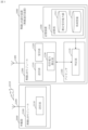
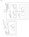
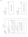
- FIG. 1 is a diagram illustrating a configuration example of a wireless LAN communication device and an on-vehicle device according to a first embodiment
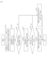
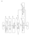
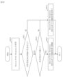
- FIG. 5 is a flowchart illustrating an example of the operation of the determination unit of the wireless LAN communication device according to the first embodiment
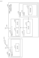
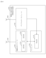
- FIG. 7 is a diagram illustrating a configuration example of a wireless LAN communication device and an on-vehicle device according to a second embodiment.
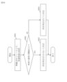
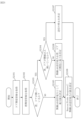
- 12 is a flowchart illustrating an example of the operation of the determination unit of the wireless LAN communication device according to the second embodiment.
- 12 is a diagram illustrating a configuration example of a wireless LAN communication device and an on-vehicle device according to Embodiment 3.
- FIG. 3 is a diagram illustrating a configuration example of a wireless LAN communication device and an on-vehicle device according to Embodiment 3.
- FIG. 12 is a flowchart illustrating an example of the operation of the determination unit of the wireless LAN communication device according to the third embodiment.
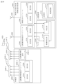
- FIG. 7 is a diagram showing a configuration example of a wireless LAN communication device and an on-vehicle device according to a fourth embodiment.
- 12 is a flowchart illustrating an example of the operation of the determination unit of the wireless LAN communication device according to Embodiment 4.
- FIG. 7 is a diagram showing an example of distance measurement using short-range wireless communication according to Embodiment 4;
- FIG. 12 is a diagram showing a configuration example of a wireless LAN communication device and an on-vehicle device according to a fifth embodiment.
- FIG. 12 is a flowchart illustrating an example of the operation of the determination unit of the wireless LAN communication device according to the fifth embodiment.
- FIG. 12 is a diagram showing a configuration example of a wireless LAN communication device and an on-vehicle device according to a sixth embodiment.
- 13 is a flowchart illustrating an example of the operation of the determination unit of the wireless LAN communication device according to the sixth embodiment.
- FIG. 7 is a diagram showing a configuration example of a wireless LAN communication device according to a seventh embodiment.
- 12 is a flowchart illustrating an example of the operation of the determination unit of the wireless LAN communication device according to Embodiment 7.
- 13 is a flowchart illustrating the operation of the determination unit of the wireless LAN communication device according to Embodiment 8.
- FIG. 12 is a diagram showing a configuration example of a wireless LAN communication device and an on-vehicle device according to a ninth embodiment.
- FIG. 13 is a flowchart illustrating an example of the operation of the on-vehicle device location determination correspondence determination unit according to Embodiment 9.
- FIG. 13 is a flowchart illustrating an example of the operation of the on-vehicle device location determination correspondence determination unit according to Embodiment 9.
- FIG. 10 is a diagram illustrating a configuration example of a wireless LAN communication device and an on-vehicle device according to a tenth embodiment.
- FIG. 12 is a flowchart illustrating an example of the operation of the transmission output determining section of the on-vehicle device according to Embodiment 10.
- 12 is a flowchart illustrating an example of the operation of the transmission output determining section of the on-vehicle device according to Embodiment 10.
- FIG. 1 shows a configuration example of a wireless LAN communication device 1000 and an on-vehicle device 2000 according to the present embodiment.
- the on-vehicle device 2000 is placed in the cabin of an automobile (hereinafter also referred to as a vehicle). Further, an antenna 2200 provided in the on-vehicle device 2000 is also arranged inside the vehicle interior.
- Wireless LAN communication device 1000 is a portable wireless communication device.
- the wireless LAN communication device 1000 can be carried by the user of the wireless LAN communication device 1000. Therefore, the wireless LAN communication device 1000 may be located outside the vehicle or may be located inside the vehicle.
- a method of determining whether wireless LAN communication device 1000 is located inside the vehicle using only antenna 2200 inside the vehicle will be described. That is, in this embodiment, a determination method for determining whether the wireless LAN communication device 1000 is located inside the vehicle without using an antenna outside the vehicle as in Patent Document 1 will be described. Note that a program for implementing the determination method by the wireless LAN communication device 1000 corresponds to a determination program.
- the onboard device 2000 includes a wireless LAN module 2100.
- Wireless LAN module 2100 includes a transmitter 2110. Transmitting section 2110 transmits wireless LAN signal 2210 via antenna 2200.
- the wireless LAN signal 2210 includes identification information of the onboard device 2000.
- the identification information of the onboard device 2000 is, for example, an ESSID (Extended Service Set Identifier). Further, the identification information of the on-vehicle device 2000 may be the MAC (Media Access Control) address of the wireless LAN module 2100 of the on-vehicle device 2000.
- the wireless LAN module 2100 of the vehicle-mounted device 2000 operates as an AP (Access Point).
- the wireless LAN signal 2210 is a Beacon frame periodically transmitted by the AP.
- the wireless LAN signal 2210 is not limited to a Beacon frame as long as it is a frame that is transmitted periodically.
- Wireless LAN communication device 1000 is a computer.
- the wireless LAN communication device 1000 includes hardware such as a processor 1100, a storage device 1300, a wireless LAN module 1200, and a wireless LAN antenna 1400.
- Processor 1100 is connected to other hardware via signal lines and controls these hardware.
- Processor 1100 is an IC (Integrated Circuit) that performs processing. Specifically, processor 1100 is a CPU (Central Processing Unit). Processor 1100 executes determination section 1110. Details of the determination unit 1110 will be described later.
- the determination unit 1110 is realized by, for example, a program. A program that implements the functions of the determination unit 1110 is stored in an auxiliary storage device, which will be described later. A program that implements the determination unit 1110 is loaded from the auxiliary storage device to a memory that will be described later. Then, the processor 1100 executes this program to perform the operation of the determination unit 1110, which will be described later.
- Storage device 1300 includes an auxiliary storage device and memory.
- the auxiliary storage device is a ROM (Read Only Memory), a flash memory, or an HDD (Hard Disk Drive).
- the memory is RAM (Random Access Memory).
- Storage unit 1310 is realized by storage device 1300.
- the storage unit 1310 is specifically implemented by a memory, but may be implemented by both an auxiliary storage device and a memory.
- the storage unit 1310 stores an estimated received power value 1311 and vehicle information 1312.
- the estimated received power value 1311 is the value of the received power estimated to be measured by the wireless LAN communication device 1000 when the wireless LAN communication device 1000 receives the wireless LAN signal 2210 wirelessly transmitted from the onboard device 2000 inside the vehicle. It is.
- the estimated received power value 1311 is, for example, a received power distribution indicating an estimated value of received power for each position in the vehicle interior.
- the estimated received power value 1311 may be the minimum value of received power (hereinafter referred to as a received power threshold) that is estimated when the wireless LAN communication device 1000 receives the wireless LAN signal 2210 inside the vehicle.
- the vehicle information 1312 includes onboard equipment identification information.
- the on-vehicle device identification information is identification information of the on-vehicle device 2000.
- the on-vehicle device identification information is the ESSID, as described above. Further, the on-vehicle device identification information may be the MAC address of the wireless LAN module 2100 of the on-vehicle device 2000.
- the storage unit 1310 stores the estimated received power value 1311, but a configuration may also be adopted in which the estimated received power value 1311 is notified from the onboard device 2000 to the wireless LAN communication device 1000. In this case, storage section 1310 does not store estimated received power value 1311.
- the wireless LAN module 1200 includes a transmitting section 1210, a receiving section 1220, and a received power measuring section 1230.
- the transmitter 1210 transmits a wireless LAN signal (not shown in FIG. 1) to the onboard device 2000.
- the transmitter 1210 transmits wireless LAN signals in the 5.2 GHz band, but may be capable of transmitting signals in other frequency bands.
- Receiving section 1220 receives communication data via wireless LAN antenna 1400. It is assumed that the communication data received by the receiving unit 1220 includes identification information of the transmission source of the communication data. The identification information of the transmission source of communication data is hereinafter referred to as transmission source identification information.
- the receiving unit 1229 receives the wireless LAN signal 2210, which is communication data transmitted from the vehicle-mounted device 2000. On the other hand, if the wireless LAN communication device 1000 is located outside the vehicle, it may receive communication data transmitted from a transmission source other than the on-vehicle device 2000. Note that in this embodiment, when receiving the wireless LAN signal 2210, the receiving section 1220 receives the wireless LAN signal 2210 in the 5.2 GHz band.
- the receiving unit 1220 may be able to receive signals in other frequency bands from the on-vehicle device 2000. If the receiving unit 1220 is capable of receiving a signal in another frequency band from the on-vehicle device 2000, the on-vehicle device 2000 receives the wireless LAN signal 2210 in another frequency band that the receiving unit 1220 can receive, instead of the 5.2 GHz band. may be sent. The processing performed by the receiving unit 1220 corresponds to receiving processing.
- Received power measuring section 1230 measures received power when receiving section 1220 receives communication data. That is, received power measuring section 1230 measures the received power of the signal received by receiving section 1220 as communication data. Information indicating the received power measured by the received power measuring section 1230 will be referred to as received power information below.
- the communication data received by the receiving unit 1220 includes the wireless LAN signal 2210 from the on-vehicle device 2000 and communication data from a transmission source other than the on-vehicle device 2000.
- the processing performed by the received power measurement section 1230 corresponds to received power measurement processing.
- Determination unit 1110 determines whether wireless LAN communication device 1000 is located inside the vehicle. The determination by determination unit 1110 as to whether wireless LAN communication device 1000 is present in the vehicle interior is also referred to as location determination. More specifically, the determination unit 1110 compares the identification information of the transmission source (transmission source identification information) of the communication data received by the reception unit 1220 and the onboard equipment identification information of the vehicle information 1312. Further, the determining section 1110 compares the received power value measured by the received power measuring section 1230 (the value indicated in the received power information) and the estimated received power value 1311.
- transmission source identification information transmission source identification information
- the determining section 1110 compares the received power value measured by the received power measuring section 1230 (the value indicated in the received power information) and the estimated received power value 1311.
- the determination unit 1110 determines that the wireless LAN communication device 1000 is in the vehicle interior. It is determined that the location exists. On the other hand, if the source identification information and the onboard device identification information do not match, and/or if the measured received power value and the estimated received power value 1311 do not match, the determination unit 1110 determines that the wireless LAN communication device 1000 It is determined that the vehicle is located outside the vehicle. The processing performed by the determination unit 1110 corresponds to determination processing.
- the operation example shown in FIG. 2 is an operation example of the determination unit 1110.
- the determination unit 1110 acquires transmission source identification information and received power information. More specifically, determination section 1110 acquires transmission source identification information from reception section 1220. Further, determination section 1110 acquires received power information from received power measurement section 1230.
- step S102 the determination unit 1110 obtains vehicle information 1312 from the storage device 1300.
- step S103 the determination unit 1110 compares the transmission source identification information obtained in step S101 and the onboard equipment identification information of the vehicle information 1312 obtained in step S102. If the transmission source identification information and the onboard device identification information match, the process advances to step S104. On the other hand, if the transmission source identification information and the onboard device identification information do not match, the process proceeds to step S107.
- step S104 the determination unit 1110 obtains the estimated received power value 1311 from the storage device 1300.
- the estimated received power value 1311 is stored in the storage device 1300, but the estimated received power value 1311 may be included in the wireless LAN signal 2210.
- determination section 1110 obtains estimated received power value 1311 included in wireless LAN signal 2210 from received power measuring section 1230.
- step S105 the determination unit 1110 compares the value of the received power information obtained in step S101 and the estimated received power value 1311 obtained in step S104. If the estimated received power value 1311 is the received power distribution inside the vehicle, the determination unit 1110 uses the minimum received power value in the received power distribution. Then, determination section 1110 determines whether the value of the received power information is greater than or equal to the minimum received power value in the received power distribution. If the estimated received power value 1311 is the received power threshold, the determination unit 1110 determines whether the value of the received power information is equal to or greater than the received power threshold.
- step S106 If the value of the received power information matches the estimated received power value 1311, that is, if the value of the received power information is greater than or equal to the minimum received power value in the received power distribution, or if the value of the received power information matches the estimated received power value 1311, If the power is equal to or greater than the power threshold, the process advances to step S106. On the other hand, if the received power information value does not match the estimated received power value 1311, that is, if the received power information value is less than the minimum received power value in the received power distribution, or if the received power information value is less than the reception power threshold, the process advances to step S107.
- the determining unit 1110 determines that the wireless LAN communication device 1000 is located inside the vehicle.
- the determining unit 1110 sets the transmitting unit 1210 of the wireless LAN module 1200 so that it can transmit a 5.2 GHz band wireless LAN signal. More specifically, the determination unit 1110 sets the transmission power (hereinafter also referred to as “wireless LAN transmission power”) when the transmission unit 1210 wirelessly transmits to the onboard device 2000 in the 5.2 GHz band to, for example, 40 mW. .
- step S107 determination unit 1110 determines that wireless LAN communication device 1000 is located outside the vehicle.
- the determining unit 1110 then sets the transmitting unit 1210 of the wireless LAN module 1200 so that it cannot transmit a 5.2 GHz band wireless LAN signal.
- the location can be determined without using an antenna outside the vehicle.
- the wireless LAN transmission power in the 5.2 GHz band can be limited to a predetermined value (40 mW).
- the wireless LAN communication device 1000 is located outside the vehicle, it can be controlled so that wireless transmission in the 5.2 GHz band is not possible.
- Embodiment 2 In this embodiment, differences from Embodiment 1 will be mainly explained. Note that matters not described below are the same as in the first embodiment.
- FIG. 3 shows an example of the configuration of wireless LAN communication device 1000 and vehicle-mounted device 2000 according to the present embodiment.
- the received power measuring section 1230 is omitted.
- vehicle information 1312 is held in the storage unit 1310.
- Other elements are the same as in FIG.
- the transmitting unit 2110 of the vehicle-mounted device 2000 transmits the wireless LAN signal 2210 with a transmission power that can only be received by a wireless communication device located inside the vehicle. Therefore, in this embodiment, if the receiving unit 1220 can receive the wireless LAN signal 2210 and the source identification information included in the wireless LAN signal 2210 matches the on-vehicle device identification information of the vehicle information 1312, The determination unit 1110 can determine that the wireless LAN communication device 1000 is located inside the vehicle.
- the operation example shown in FIG. 4 is an operation example of the determination unit 1110.
- step S201 operations other than step S201 are similar to those shown in FIG. 2.
- step S201 the determination unit 1110 acquires source identification information from the reception unit 1220 of the wireless LAN module 1200.
- step S102 the determination unit 1110 obtains vehicle information 1312 from the storage device 1300.
- step S103 the determination unit 1110 compares the transmission source identification information obtained in step S101 and the onboard equipment identification information of the vehicle information 1312 obtained in step S102. If the transmission source identification information and the onboard device identification information match, the process advances to step S106. On the other hand, if the transmission source identification information and the onboard device identification information do not match, the process proceeds to step S107.
- step S106 the determining unit 1110 determines that the wireless LAN communication device 1000 is located inside the vehicle.
- the determining unit 1110 sets the transmitting unit 1210 of the wireless LAN module 1200 so that it can transmit a 5.2 GHz band wireless LAN signal. More specifically, the determination unit 1110 sets the transmission power (wireless LAN transmission power) when the transmission unit 1210 wirelessly transmits to the onboard device 2000 in the 5.2 GHz band to, for example, 40 mW.
- step S107 determination unit 1110 determines that wireless LAN communication device 1000 is located outside the vehicle.
- the determining unit 1110 then sets the transmitting unit 1210 of the wireless LAN module 1200 so that it cannot transmit a 5.2 GHz band wireless LAN signal.
- the location can be determined without using an antenna outside the vehicle. Further, according to this embodiment as well, when the wireless LAN communication device 1000 is located inside the vehicle, the wireless LAN transmission power in the 5.2 GHz band can be limited to the default value (40 mW). On the other hand, if the wireless LAN communication device 1000 is located outside the vehicle, it can be controlled so that wireless transmission in the 5.2 GHz band is not possible.
- the transmitting unit 2110 of the vehicle-mounted device 2000 transmits the wireless LAN signal 2210 with a transmission power that can only be received by a wireless communication device located inside the vehicle. Therefore, in this embodiment, if the receiving unit 1220 can receive the wireless LAN signal 2210, and the source identification information included in the wireless LAN signal 2210 matches the onboard device identification information, the determining unit 1110 can receive the wireless LAN signal 2210. , it can be determined that the wireless LAN communication device 1000 is located inside the vehicle. In this way, in this embodiment, since there is no need to measure received power, received power measuring section 1230 and estimated received power value 1311 described in Embodiment 1 can be omitted.
- Embodiment 3 In this embodiment, differences from Embodiment 2 will be mainly explained.
- the wireless LAN communication device 1000 determines whether or not the wireless LAN communication device 1000 is located inside the vehicle based on the distance between the transmission source of communication data and the wireless LAN communication device 1000.
- the wireless LAN communication device 1000 determines whether or not the wireless LAN communication device 1000 is located inside the vehicle based on the distance between the transmission source of communication data and the wireless LAN communication device 1000.
- the wireless LAN communication device 1000 determines whether or not the wireless LAN communication device 1000 is located inside the vehicle based on the distance between the transmission source of communication data and the wireless LAN communication device 1000.
- FIG. 5 shows a configuration example of a wireless LAN communication device 1000 and an on-vehicle device 2000 according to the present embodiment.
- a receiving section 2120 and a distance measurement processing section 2130 are added to the wireless LAN module 2100 of the on-vehicle device 2000.
- a distance measurement processing section 1240 is added to the wireless LAN module 1200 of the wireless LAN communication device 1000.
- Other elements are the same as in FIG.
- the receiving unit 2120 of the vehicle-mounted device 2000 receives a ranging request frame 1410 and an ACK frame 1420, which will be described later, from the wireless LAN communication device 1000. Further, in the present embodiment, when the receiving unit 2120 receives the ranging request frame 1410, the transmitting unit 2110 transmits the ranging frame 2220 to the wireless LAN communication device 1000 as a response to the ranging request frame 1410. .
- the distance measurement processing unit 2130 holds the transmission time T1 of the distance measurement frame 2220 and the reception time T4 of the ACK frame 1420.
- the distance measurement processing unit 1240 of the wireless LAN communication device 1000 holds the reception time T2 of the distance measurement frame 2220 and the transmission time T3 of the ACK frame 1420. Further, the distance measurement processing unit 1240 measures the distance D between the wireless LAN communication device 1000 and the vehicle-mounted device 2000 using the transmission time T1, the reception time T2, the transmission time T3, and the reception time T4. Furthermore, the distance measurement processing unit 1240 notifies the determination unit 1110 of the measured distance D between the wireless LAN communication device 1000 and the vehicle-mounted device 2000.
- the determination unit 1110 determines whether the wireless LAN is connected based on the distance D between the wireless LAN communication device 1000 and the on-vehicle device 2000 notified from the distance measurement processing unit 1240 and the distance d included in the vehicle information 1312. It is determined whether the communication device 1000 is located inside the vehicle.
- the vehicle information 1312 indicates the distance d from the mounting position of the antenna 2200 of the on-vehicle device 2000 to the door of the vehicle.
- the storage unit 1310 stores the vehicle information 1312, but the vehicle information 1312 may be notified from the on-vehicle device 2000 to the wireless LAN communication device 1000. In this case, storage unit 1310 does not store vehicle information 1312.
- the operation example shown in FIG. 6 is an operation example of the determination unit 1110.
- step S201, step S102, and step S103 in FIG. 4 are performed. If the determination in step S103 is YES, the operation shown in FIG. 6 starts. That is, in this embodiment, similarly to Embodiment 2, the transmitter 2110 of the vehicle-mounted device 2000 transmits the wireless LAN signal 2210 with a transmission power that can only be received by a wireless communication device located inside the vehicle. Then, if the receiving unit 1220 can receive the wireless LAN signal 2210 and the source identification information included in the wireless LAN signal 2210 matches the onboard device identification information (YES in step S103), the Step S301 is performed.
- the determination unit 1110 transmits the distance measurement request frame 1410 to the wireless LAN module 2100 of the onboard device 2000 from the transmitting unit 1210 of the wireless LAN module 1200.
- the transmitter 1210 transmits the distance measurement request frame 1410 using a frequency band that can be used outdoors other than the 5.2 GHz band.
- the distance measurement request frame 1410 is an FTM (Fine Timing Measurement) Request frame defined in the IEEE 802.11 standard (Non-Patent Document 1).
- the receiving unit 2120 receives the ranging request frame 1410.
- the transmitter 2110 then transmits the distance measurement frame 2220 to the wireless LAN communication device 1000 as a response to the distance measurement request frame 1410.
- the ranging frame 2220 is an FTM frame.
- the receiving unit 1220 receives the ranging frame 2220.
- the transmitting unit 1210 transmits the ACK frame 1420 to the vehicle-mounted device 2000 as a response to the ranging frame 2220.
- the receiving unit 2120 receives the ACK frame 1420.
- the distance measurement processing unit 2130 holds the transmission time T1 of the distance measurement frame 2220 and the reception time T4 of the ACK frame 1420. Furthermore, in the wireless LAN communication device 1000, the distance measurement processing unit 1240 holds the reception time T2 of the distance measurement frame 2220 and the transmission time T3 of the ACK frame 1420.
- the distance measurement processing unit 2130 of the vehicle-mounted device 2000 generates a notification frame 2230 that notifies the transmission time T1 and the reception time T4, and the transmission unit 2110 transmits the notification frame 2230 to the wireless LAN communication device 1000.
- Notification frame 2230 is also an FTM frame.
- the ranging processing section 1240 acquires the notification frame 2230 via the receiving section 1220.
- the distance measurement processing unit 1240 applies the transmission time T1, the reception time T2, the transmission time T3, and the reception time T4 to equation (1) to obtain RTT (Round Trip Time).
- RTT (T4-T1)-(T3-T2) Formula (1)
- the distance measurement processing unit 1240 divides the obtained RTT by the speed of light c to obtain the distance D between the wireless LAN communication device 1000 and the vehicle-mounted device 2000, according to equation (2).
- the speed of light c is 299,792,458 m/s.
- D (RTT/2) ⁇ c Formula (2)
- step S302 of FIG. 6 the determination unit 1110 obtains the distance D determined as described above from the distance measurement processing unit 1240 as the distance measurement result.
- step S303 the determination unit 1110 obtains vehicle information 1312 from the storage device 1300.
- step S304 the determination unit 1110 compares the distance D obtained in step S302 and the distance d of the vehicle information 1312 obtained in step S303.
- the distance d is the distance from the mounting position of the antenna 2200 to the vehicle door. Then, if the distance D and the distance d match, that is, if the distance D is less than or equal to the distance d, the process advances to step S106. On the other hand, if the transmission source identification information and the onboard device identification information of the vehicle information 1312 do not match, that is, if the distance D is greater than the distance d, the process advances to step S107.
- Step S106 and Step S107 are the same as shown in Embodiment 1, so their explanation will be omitted.
- steps S201, S102, and S103 in FIG. 4 are performed before the operation in FIG. 6.
- steps S101 to S105 in FIG. 2 may be performed before the operation in FIG. 6.
- the determination in step S105 is YES, the operation shown in FIG. 6 starts.
- a received power measuring section 1230 and an estimated received power value 1311 are added to the configuration of the wireless LAN communication device 1000 in FIG. 5.
- Embodiment 4 In this embodiment, differences from Embodiment 3 will be mainly explained.
- distance measurement was performed based on RTT, but in this embodiment, distance estimation is performed using AoA (Angle of Arrival).
- AoA is a function added in Bluetooth 5.1 (Non-Patent Document 4).
- Bluetooth is a registered trademark. Note that matters not described below are the same as in the third embodiment.
- FIG. 7 shows an example of the configuration of wireless LAN communication device 1000 and vehicle-mounted device 2000 according to the present embodiment.
- a short-range wireless communication module 1500 and a short-range wireless communication antenna 1600 are added to the wireless LAN communication device 1000.
- a short-range wireless communication module 2300-1, a short-range wireless communication module 2300-2, a processor 2500, an antenna 2400-1, and an antenna 2400-2 are added to the on-vehicle device 2000.
- the short-range wireless communication module 1500 performs short-range wireless communication with the short-range wireless communication module 2300-1 and the short-range wireless communication module 2300-2 of the onboard device 2000. Specifically, the short-range wireless communication module 1500 performs short-range wireless communication using Bluetooth (registered trademark).
- the transmitter 1510 transmits an AoA measurement frame 1610, which will be described later, to the wireless LAN communication device 1000 using the short-range wireless communication antenna 1600.
- the receiving unit 1520 receives a notification frame 2410, which will be described later, from the wireless LAN communication device 1000 using the short-range wireless communication antenna 1600.
- vehicle information 1312 includes the distance from the mounting position of antenna 2400-1 to the vehicle door (hereinafter referred to as distance d1), and the distance from the mounting position of antenna 2400-2 to the vehicle door (hereinafter referred to as distance d1). (hereinafter referred to as distance d2).
- the distance d1 is, for example, the distance from the mounting position of the antenna 2400-1 to the farthest door.
- distance d2 is, for example, the distance from the mounting position of antenna 2400-2 to the farthest door.
- the storage unit 1310 stores the vehicle information 1312, but the vehicle information 1312 may be notified from the on-vehicle device 2000 to the wireless LAN communication device 1000. In this case, storage unit 1310 does not store vehicle information 1312.
- determination unit 1110 determines the estimated distance D1 between antenna 2400-1 and short-range wireless communication antenna 1600 and the estimated distance D1 between antenna 2400-2 and short-range wireless communication antenna 1600. Based on the distance D2 and the distances d1 and d2 of the vehicle information 1312, it is determined whether the wireless LAN communication device 1000 is located inside the vehicle.
- the short-range wireless communication module 2300-1 and the short-range wireless communication module 2300-2 each perform short-range wireless communication with the short-range wireless communication module 1500.
- Transmitting section 2310 transmits notification frame 2410 to wireless LAN communication device 1000 using antenna 2400-1.
- Receiving section 2320 receives AoA measurement frame 1610 from wireless LAN communication device 1000 using antenna 2400-1.
- the AoA processing unit 2330 estimates AoA when the AoA measurement frame 1610 is received.
- the internal configuration of the short-range wireless communication module 2300-2 is not shown in FIG. 7 for drawing reasons, the short-range wireless communication module 2300-2 also has the same internal structure as the short-range wireless communication module 2300-1. It shall have a configuration.
- the distance estimation unit 2510 estimates the antenna 2400 based on the AoA estimation result by the AoA processing unit 2330 of the short-range wireless communication module 2300-1 and the AoA estimation result by the AoA processing unit 2330 of the short-range wireless communication module 2300-2. -1 and the short-range wireless communication antenna 1600, and the distance D2 between the antenna 2400-2 and the short-range wireless communication antenna 1600 are estimated.
- the distance estimation section 2510 is realized by a program similarly to the determination section 1110. A program that implements the functions of distance estimator 2510 is executed by processor 2500.
- wireless LAN signal 2210 is transmitted from wireless LAN module 2100 to wireless LAN module 1200 via antenna 2200.
- the operation example shown in FIG. 8 is an operation example of the determination unit 1110.
- step S103 the operation shown in FIG. 8 starts. That is, in this embodiment, similarly to Embodiment 2, the transmitter 2110 of the vehicle-mounted device 2000 transmits the wireless LAN signal 2210 with a transmission power that can only be received by a wireless communication device located inside the vehicle. Then, if the receiving unit 1220 can receive the wireless LAN signal 2210 and the source identification information included in the wireless LAN signal 2210 matches the onboard device identification information of the vehicle information 1312 (YES in step S103), , step S401 in FIG. 8 is performed.
- step S401 the determining unit 1110 transmits the AoA measurement frame 1610 from the transmitting unit 1510 of the short-range wireless communication module 1500. More specifically, determination section 1110 instructs transmission section 1510 of short-range wireless communication module 1500 to transmit AoA measurement frame 1610. Transmitter 1510 transmits AoA measurement frame 1610 from short-range wireless communication antenna 1600.
- the short-range wireless communication module 2300-1 receives the AoA measurement frame 1610 via the antenna 2400-1. Further, the short-range wireless communication module 2300-2 receives the AoA measurement frame 1610 via the antenna 2400-2. Then, in each of the short-range wireless communication module 2300-1 and the short-range wireless communication module 2300-2, the AoA processing unit 2330 estimates the AoA.
- the AoA estimation result of the AoA processing unit 2330 of the short-range wireless communication module 2300-1 will be referred to as estimation result ⁇ 1. Further, the AoA estimation result of the AoA processing unit 2330 of the short-range wireless communication module 2300-2 is referred to as estimation result ⁇ 2.
- the AoA processing unit 2330 of the short-range wireless communication module 2300-1 notifies the distance estimation unit 2510 of the AoA estimation result ⁇ 1. Further, the AoA processing unit 2330 of the short-range wireless communication module 2300-2 also notifies the distance estimating unit 2510 of the AoA estimation result ⁇ 2.
- the distance between antenna 2400-1 and antenna 2400-2 is referred to as distance D3.
- the distance D3 is determined when the on-vehicle device 2000 is installed, and therefore is held in the on-vehicle device 2000 as known information.
- the relationship among the AOA estimation result ⁇ 1, the AOA estimation result ⁇ 2, the distance D1, the distance D2, and the distance D3 is as shown in FIG.
- the distance estimation unit 2510 estimates the distance D1 and the distance D2 from the AOA estimation result ⁇ 1, the AOA estimation result ⁇ 2, and the distance D3. Specifically, the distance estimation unit 2510 estimates the distance D1 and the distance D2 according to the following equation (3).
- the distance estimation unit 2510 transmits a notification frame 2410 notifying the distance D1 and the distance D2 to the wireless LAN communication device 1000 via either the antenna 2400-1 or the antenna 2400-2.
- the receiving unit 1520 of the short-range wireless communication module 1500 receives the notification frame 2410. Then, in step S402 of FIG. 8, the determination unit 1110 obtains the distance D1 and the distance D2 from the reception unit 1520.
- step S403 the determination unit 1110 obtains vehicle information 1312 from the storage device 1300.
- step S404 the determination unit 1110 compares the distance D and distance D2 obtained in step S402 with the distance d1 and distance d2 of the vehicle information 1312 obtained in step S403. If the distance D and the distance D2 match the distance d1 and the distance d2, that is, if the distance D1 is less than or equal to the distance d1 and the distance D2 is less than or equal to the distance d2, the process proceeds to step S106. On the other hand, if the distance D and the distance D2 do not match the distance d1 and the distance d2, that is, if the distance D1 is larger than the distance d1 and/or if the distance D2 is larger than the distance d2, the process proceeds to step S107.
- Step S106 and Step S107 are the same as shown in Embodiment 1, so their explanation will be omitted.
- steps S201, S102, and S103 in FIG. 4 are performed before the operation in FIG. 8.
- steps S101 to S105 in FIG. 2 may be performed before the operation in FIG. 8.
- the determination in step S105 is YES, the operation shown in FIG. 8 starts.
- a received power measuring section 1230 and an estimated received power value 1311 are added to the configuration of the wireless LAN communication device 1000 in FIG.
- Embodiment 5 In this embodiment, differences from Embodiment 4 will be mainly explained.
- the onboard device 2000 performs distance estimation using AoA
- the wireless LAN communication device 1000 performs distance estimation using AoD (Angle of Departure).
- AoD is a function added in Bluetooth 5.1 (non-patent document 4). Note that matters not described below are the same as in the third embodiment.
- FIG. 10 shows a configuration example of a wireless LAN communication device 1000 and an on-vehicle device 2000 according to the present embodiment.
- the AoA processing unit 2330, processor 2500, and distance estimating unit 2510 are omitted in the on-vehicle device 2000.
- the internal configuration of the short-range wireless communication module 2300-2 is not shown for drawing reasons, but the short-range wireless communication module 2300-2 also It has the same internal configuration as 1.
- short-range wireless communication module 2300-1 transmits AoD frame 2420-1 to wireless LAN communication device 1000 using antenna 2400-1.
- Near field wireless communication module 2300-2 also transmits AoD frame 2420-2 to wireless LAN communication device 1000 using antenna 2400-2.
- wireless LAN module 2100 illustration of the wireless LAN module 2100, antenna 2200, and wireless LAN signal 2210 is omitted for drawing reasons. However, similarly to Embodiments 2 and 3, it is assumed that wireless LAN signal 2210 is transmitted from wireless LAN module 2100 to wireless LAN module 1200 via antenna 2200.
- a distance estimation unit 1120 is added to the wireless LAN communication device 1000.
- the distance estimating unit 1120 like the determining unit 1110, is realized by a program.
- the distance estimation section 1120 performs the same operation as the AoA processing section 2330 and the distance estimation section 2510 in FIG. 7 .
- the receiving unit 1520 receives the AoD frame 2420-1 and the AoD frame 2420-2. Then, the receiving section 1520 outputs the received AoD frame 2420-1 and AoD frame 2420-2 to the distance estimating section 1120.
- Distance estimation section 1120 estimates AoD using AoD frame 2420-1 and AoD frame 2420-2.
- the AoD estimation result using the AoD frame 2420-1 is referred to as estimation result ⁇ 1.
- the AoD estimation result using the AoD frame 2420-2 is referred to as estimation result ⁇ 2.
- Distance estimating section 1120 calculates distance D1 and distance D2 according to equation (3) shown in Embodiment 4.
- Distance D1 is the distance between antenna 2400-1 and short-range wireless communication antenna 1600, as shown in the fourth embodiment.
- distance D2 is the distance between antenna 2400-2 and short-range wireless communication antenna 1600.
- distance D3 is the distance between antenna 2400-1 and antenna 2400-2.
- the distance D3 is determined when the on-vehicle device 2000 is installed, and therefore is included in the vehicle information 1312 as known information.
- the relationship among the estimation result ⁇ 1, the estimation result ⁇ 2, the distance D1, the distance D2, and the distance D3 is as shown in FIG.
- the distance estimation unit 1120 notifies the determination unit 1110 of the calculated distance D1 and distance D2.
- vehicle information 1312 shows the distance d1 from the mounting position of antenna 2400-1 to the vehicle door, and the distance d2 from the mounting position of antenna 2400-2 to the vehicle door.
- determination unit 1110 determines whether wireless LAN communication device 1000 is located inside the vehicle based on distance D1 and distance D2 notified from distance estimation unit 1120 and distance d1 and distance d2 of vehicle information 1312. Determine whether or not.
- FIG. 11 is the operation of the determination unit 1110. Also in this embodiment, it is assumed that steps S201, S102, and S103 in FIG. 4 are performed first. If the determination in step S103 is YES, the operation of FIG. 11 starts. That is, in this embodiment, similarly to Embodiment 2, the transmitter 2110 of the vehicle-mounted device 2000 transmits the wireless LAN signal 2210 with a transmission power that can only be received by a wireless communication device located inside the vehicle.
- step S501 in FIG. 11 is performed.
- step S501 the determining unit 1110 transmits the AoD instruction frame 1620 from the transmitting unit 1510 of the short-range wireless communication module 1500. More specifically, determination section 1110 instructs transmission section 1510 of short-range wireless communication module 1500 to transmit AoD instruction frame 1620. Transmitter 1510 transmits AoD instruction frame 1620 from short-range wireless communication antenna 1600.
- the AoD instruction frame 1620 is a frame that instructs the onboard device 2000 to transmit the AoD frame 2420-1 and the AoD frame 2420-2.
- the short-range wireless communication module 2300-1 receives the AoD instruction frame 1620 via the antenna 2400-1. Further, the short-range wireless communication module 2300-2 receives the AoD instruction frame 1620 via the antenna 2400-2. Then, the transmitter 2310 of the short-range wireless communication module 2300-1 transmits the AoD frame 2420-1 via the antenna 2400-1. Further, the transmitter 2310 of the short-range wireless communication module 2300-2 transmits the AoD frame 2420-2 via the antenna 2400-2.
- the receiving unit 1520 receives the AoD frame 2420-1 and the AoD frame 2420-2. Then, the distance estimation unit 1120 calculates the estimation result ⁇ 1 and the estimation result ⁇ 2 from the AoD frame 2420-1 and the AoD frame 2420-2. Further, the distance estimating unit 1120 estimates the distance D1 and the distance D2 according to equation (3) using the estimation result ⁇ 1, the estimation result ⁇ 2, and the distance D3. The distance estimating unit 1120 then notifies the determining unit 1110 of the estimated distance D1 and distance D2.
- step S502 of FIG. 11 the determination unit 1110 obtains the distance D1 and the distance D2 from the distance estimation unit 1120.
- step S503 the determination unit 1110 obtains vehicle information 1312 from the storage device 1300.
- step S504 the determination unit 1110 compares the distance D and distance D2 obtained in step S502 with the distance d1 and distance d2 of the vehicle information 1312 obtained in step S503. If the distance D and the distance D2 match the distance d1 and the distance d2, that is, if the distance D1 is less than or equal to the distance d1 and the distance D2 is less than or equal to the distance d2, the process proceeds to step S106. On the other hand, if the distance D and the distance D2 do not match the distance d1 and the distance d2, that is, if the distance D1 is larger than the distance d1 and/or if the distance D2 is larger than the distance d2, the process proceeds to step S107.
- Step S106 and Step S107 are the same as shown in Embodiment 1, so their explanation will be omitted.
- steps S201, S102, and S103 in FIG. 4 are performed before the operation in FIG. 11.
- steps S101 to S105 in FIG. 2 may be performed before the operation in FIG. 11.
- the determination in step S105 is YES
- the operation in FIG. 11 starts.
- a received power measuring section 1230 and an estimated received power value 1311 are added to the configuration of the wireless LAN communication device 1000 in FIG.
- Embodiment 6 In this embodiment, differences from Embodiment 2 will be mainly explained. Note that matters not described below are the same as in the second embodiment.
- FIG. 12 shows a configuration example of a wireless LAN communication device 1000 and an on-vehicle device 2000 according to this embodiment.
- a wireless LAN signal 2240 is transmitted from the onboard device 2000 instead of the wireless LAN signal 2210.
- the wireless LAN signal 2240 includes source identification information.
- the wireless LAN signal 2240 includes IE (Information Element) information.
- the IE information includes onboard device information indicating that the transmission source of the wireless LAN signal 2240 is the onboard device 2000.
- Vender Specific IE can be used as the IE information. By using Vender Specific IE as the IE information, it is possible to include the onboard device information in the wireless LAN signal 2240 without affecting other wireless LAN systems.
- IE information other than Vender Specific IE may include onboard device information.
- the determining unit 1110 determines whether the wireless LAN communication device 1000 is located inside the vehicle based on whether the wireless LAN signal 2240 includes IE information.
- FIG. 12 illustration of the storage device 1300, storage unit 1310, and vehicle information 1312 is omitted. However, in this embodiment as well, it is assumed that these exist as in the second embodiment.
- the operation example shown in FIG. 13 is an operation example of the determination unit 1110.
- step S103 the operation shown in FIG. 13 starts. That is, in this embodiment, similarly to Embodiment 2, the transmitting unit 2110 of the onboard device 2000 transmits the wireless LAN signal 2240 with a transmission power that can only be received by a wireless communication device located inside the vehicle. Then, if the receiving unit 1220 can receive the wireless LAN signal 2240 and the source identification information included in the wireless LAN signal 2240 matches the onboard device identification information of the vehicle information 1312 (YES in step S103), , step S601 in FIG. 13 is performed.
- step S601 the determination unit 1110 determines whether the wireless LAN signal 2240 received from the onboard device 2000 includes onboard device information. That is, the determination unit 1110 determines whether the wireless LAN signal 2240 includes IE information.
- step S106 If the wireless LAN signal 2240 includes onboard device information, the process advances to step S106. On the other hand, if the wireless LAN signal 2240 does not include the onboard device information, the process advances to step S107.
- Step S106 and Step S107 are the same as shown in Embodiment 1, so their explanation will be omitted.
- steps S201, S102, and S103 in FIG. 4 are performed before the operation in FIG. 13.
- steps S101 to S105 in FIG. 2 may be performed before the operation in FIG. 13.
- the determination in step S105 is YES, the operation in FIG. 13 starts.
- a received power measuring section 1230 and an estimated received power value 1311 are added to the configuration of the wireless LAN communication device 1000 in FIG. 12.
- Embodiment 7 In this embodiment, differences from Embodiment 2 will be mainly explained. Note that matters not described below are the same as in the second embodiment.
- FIG. 14 shows a configuration example of an on-vehicle device 2000 according to this embodiment. Note that the configuration of the on-vehicle device 2000 is the same as that shown in FIG. 3, so illustration is omitted. In FIG. 14, compared to FIG. 3, a digital key module 1700 and a digital key module antenna 1800 are added.
- Digital key module 1700 unlocks and locks the doors of the vehicle. Specifically, digital key module 1700 transmits a door unlocking instruction frame or locking instruction frame to the vehicle via digital key module antenna 1800.
- the unlock instruction frame is a communication frame that instructs the vehicle to unlock the door.
- the locking instruction frame is a communication frame that instructs the vehicle to lock the doors.
- the determination unit 1110 determines whether the wireless LAN communication device 1000 is located in the vehicle interior based on the result of the digital key module 1700 unlocking or locking the vehicle door.
- FIG. 14 illustration of the storage device 1300, storage unit 1310, and vehicle information 1312 is omitted. However, in this embodiment as well, it is assumed that these exist as in the second embodiment.
- the operation example shown in FIG. 15 is an operation example of the determination unit 1110.
- step S201, step S102, and step S103 in FIG. 4 are performed. If the determination in step S103 is YES, the operation shown in FIG. 15 starts. That is, in this embodiment, similarly to Embodiment 2, the transmitter 2110 of the vehicle-mounted device 2000 transmits the wireless LAN signal 2210 with a transmission power that can only be received by a wireless communication device located inside the vehicle. Then, if the receiving unit 1220 can receive the wireless LAN signal 2210 and the source identification information included in the wireless LAN signal 2210 matches the onboard device identification information of the vehicle information 1312 (YES in step S103), , step S701 in FIG. 15 is performed.
- step S701 the determination unit 1110 determines whether the digital key module 1700 has notified that the door has been unlocked. If it has been notified that the door has been unlocked, the process advances to step S106. On the other hand, if it has been notified that the door has been locked, the process advances to step S107.
- Step S106 and Step S107 are the same as shown in Embodiment 1, so their explanation will be omitted.
- the location determination is performed using the execution results of unlocking/locking the doors of the vehicle. Therefore, according to this embodiment as well, the location can be determined more accurately.
- steps S201, S102, and S103 in FIG. 4 are performed before the operation in FIG. 15.
- steps S101 to S105 in FIG. 2 may be performed before the operation in FIG. 15.
- the determination in step S105 is YES, the operation shown in FIG. 15 starts.
- a received power measuring section 1230 and an estimated received power value 1311 are added to the configuration of the wireless LAN communication device 1000 in FIG. 14.
- Embodiment 8 In this embodiment, differences from Embodiment 2 will be mainly explained. In this embodiment, an example will be described in which wireless LAN communication device 1000 does not perform location determination when the speed of the vehicle is equal to or higher than a predetermined speed. Note that matters not described below are the same as in the second embodiment.
- the wireless LAN communication device 1000 and the vehicle-mounted device 2000 according to this embodiment are as shown in FIG.
- the wireless LAN signal 2210 includes information on the speed of the vehicle measured by the onboard device 2000 (hereinafter referred to as vehicle speed information).
- the operation example shown in FIG. 16 is an operation example of the determination unit 1110.
- the processing flow in FIG. 16 is executed before the processing flow in FIG. 4 is executed.
- step S801 in FIG. 16 the determination unit 1110 acquires vehicle speed information included in the wireless LAN signal 2210 from the receiving unit 1220 of the wireless LAN module 1200.
- step S802 the determining unit 1110 determines whether the speed of the vehicle indicated by the vehicle speed information is equal to or higher than a predetermined threshold.
- the threshold value is the lowest speed at which it can be determined whether the vehicle is running. For example, 5 km/h may be considered as the threshold value. If the speed of the vehicle is equal to or greater than the threshold, the process advances to step S803. On the other hand, if the speed of the vehicle is less than the threshold, the process advances to step S804.
- step S803 the determination unit 1110 determines not to perform location determination. That is, in this case, it is considered that the vehicle is running, and therefore the wireless LAN communication device 1000 is considered to be located inside the vehicle. Therefore, location determination is not necessary.
- step S804 the determination unit 1110 determines to perform location determination. Specifically, the determination unit 1110 performs the processing from step S201 in FIG. 4 onwards.
- this embodiment has been described based on the configuration of Embodiment 2.
- the operation of this embodiment may be performed based on the configuration of Embodiment 1.
- the determining unit 1110 performs the processing from step S101 onward in FIG.
- Embodiment 9 differences from Embodiment 2 will be mainly explained.
- an example will be described in which a wireless LAN communication device whose location can be determined is distinguished from a wireless LAN communication device whose location cannot be determined. Note that matters not described below are the same as in the second embodiment.
- FIG. 17 shows a configuration example of a wireless LAN communication device 1000, an on-vehicle device 2000, and an incompatible wireless LAN communication device 4000 according to the present embodiment.
- Wireless LAN communication device 1000 is the same as that shown in the second embodiment. That is, the wireless LAN communication device 1000 includes the determination unit 1110 and can determine the location. Although not shown in FIG. 17, the internal configuration of the wireless LAN communication device 1000 is the same as that shown in FIG. 3.
- the non-compatible wireless LAN communication device 4000 does not have the determination unit 1110 and cannot determine its location.
- the internal configuration of the non-compatible wireless LAN communication device 4000 is the same as that of the wireless LAN communication device 1000 shown in FIG. 3, with the determination unit 1110 omitted.
- the location determination support determination unit 2520 determines whether the wireless LAN communication device supports location determination.
- the location determination correspondence determination unit 2520 is realized by a program similarly to the determination unit 1110. A program that implements the function of the location determination correspondence determining unit 2520 is executed by the processor 2500.
- transmitter 1210 of wireless LAN communication device 1000 transmits wireless LAN frame 1010.
- the wireless LAN frame 1010 includes location determination correspondence information.
- the location determination correspondence information is information that notifies that the wireless LAN communication device 1000 includes the determination unit 1110 and can determine the location.
- the transmitter 1210 may include location determination correspondence information in the IE information.
- Vender Specific IE As the IE information, it is possible to include location determination correspondence information in the wireless LAN frame 1010 without affecting other wireless LAN systems.
- the non-compliant wireless LAN communication device 4000 transmits a wireless LAN frame 4010.
- the wireless LAN frame 4010 does not include location determination correspondence information.
- the wireless LAN frame 4010 is, for example, a normal wireless LAN frame compliant with the IEEE802.11 standard.
- FIGS. 18 and 19 are an operation example of the location determination correspondence determination unit 2520.
- the processing flows in FIGS. 18 and 19 are executed before the processing flow in FIG. 4 is executed.
- FIG. 18 is a processing flow when the vehicle-mounted device 2000 operates as an AP, and the wireless LAN communication device 1000 and the non-compatible wireless LAN communication device 4000 operate as STA (Station).
- FIG. 19 is a processing flow when the vehicle-mounted device 2000 operates as an STA, and the wireless LAN communication device 1000 and the non-compatible wireless LAN communication device 4000 operate as APs.
- step S901 in FIG. 18 the location determination correspondence determination unit 2520 acquires a wireless LAN frame from the wireless LAN module 2100.
- This wireless LAN frame is a wireless LAN frame 1010 or a wireless LAN frame 4010.
- step S902 the location determination correspondence determination unit 2520 determines whether or not the acquired wireless LAN frame includes location determination correspondence information. If the wireless LAN frame includes location determination correspondence information, the process advances to step S903. On the other hand, if the wireless LAN frame does not include the location determination correspondence information, the process advances to step S905.
- step S903 the location determination support determining unit 2520 determines whether the location determination support information indicates that location determination is possible. If it has been notified that the location determination is possible, the process advances to step S904. On the other hand, if it has not been notified that location determination is possible, the process advances to step S905. For example, if the determination unit 1110 is temporarily inoperable, the location determination correspondence information notifies that the location determination cannot be performed.
- step S904 the location determination correspondence determination unit 2520 continues the connection process for the STA that is the source of the wireless LAN frame, and continues communication with the STA that is the source. That is, in this case, transmitter 2110 transmits wireless LAN signal 2210 described in the second embodiment to wireless LAN communication device 1000. After that, the wireless LAN communication device 1000 receives the wireless LAN signal 2210 and performs the operation shown in FIG. 4.
- step S905 the location determination correspondence determining unit 2520 ends the connection process for the STA that is the source of the wireless LAN frame, and disconnects communication with the STA that is the source.
- the location determination support determining unit 2520 may use a DeAuthentication frame to disconnect communication with the STA that is the transmission source.
- the location determination correspondence determination unit 2520 acquires a Beacon frame or a Probe Response frame (hereinafter referred to as "Beacon/Probe Response") from the wireless LAN module 2100.
- This Beacon/Probe Response is a wireless LAN frame 1010 or a wireless LAN frame 4010.
- step S911 the location determination correspondence determination unit 2520 determines whether or not the acquired Beacon/Probe Response includes location determination correspondence information. If the Beacon/Probe Response includes location determination correspondence information, the process advances to step S912. On the other hand, if the Beacon/Probe Response does not include location determination correspondence information, the process advances to step S914.
- step S912 the location determination support determining unit 2520 determines whether or not the location determination support information indicates that location determination is possible. If it has been notified that the location determination is possible, the process advances to step S913. On the other hand, if it has not been notified that the location determination is possible, the process advances to step S914.
- step S913 the location determination correspondence determining unit 2520 continues the connection process of the STA that is the source of the Beacon/Probe Response, and continues communication with the STA that is the source of the Beacon/Probe Response. That is, in this case, transmitter 2110 transmits wireless LAN signal 2210 described in the second embodiment to wireless LAN communication device 1000. After that, the wireless LAN communication device 1000 receives the wireless LAN signal 2210 and performs the operation shown in FIG. 4.
- step S914 the location determination correspondence determining unit 2520 ends the connection process for the STA that is the source of the Beacon/Probe Response, and disconnects communication with the STA that is the source.
- the location determination correspondence determining unit 2520 may hold the ESSID or MAC address information of the source STA, and may decide not to make it a connection target from now on.
- the vehicle-mounted device disconnects communication with a wireless LAN communication device whose location cannot be determined. Therefore, according to the present embodiment, it is possible to prevent a wireless LAN communication device that may be located outside the vehicle from communicating with the vehicle-mounted device in the 5.2 GHz band.
- this embodiment has been described based on the configuration of Embodiment 2.
- the operation of this embodiment may be performed based on the configuration of Embodiment 1.
- the wireless LAN communication device 1000 performs the operation shown in FIG. 2 using the wireless LAN signal 2210.
- Embodiment 10 In this embodiment, differences from Embodiment 2 will be explained.
- the determination unit 1110 determines the transmission power (wireless LAN transmission power) when wirelessly transmitting to the onboard device 2000 in the 5.2 GHz band. is set to the default value (40mW).
- the onboard device 2000 determines the value of wireless LAN transmission power based on the opening degree of the vehicle door and/or vehicle window. The degree of opening of the door is the degree (percentage) of the door being open, with the fully closed state of the door being 0% and the fully open state of the door being 100%.
- the opening degree of the window is the degree (percentage) of the window being open, with the window fully closed being 0% and the window being fully open being 100%.
- determination section 1110 sets wireless LAN transmission power to the value determined by onboard device 2000. Note that matters not described below are the same as in the second embodiment.
- FIG. 20 shows a configuration example of a wireless LAN communication device 1000 and an on-vehicle device 2000 according to the present embodiment.
- the wireless LAN communication device 1000 is the same as that shown in the second embodiment.
- the onboard device 2000 includes a transmission output determining section 2530.
- the transmission output determining unit 2530 is realized by, for example, a program.
- processor 2500 executes a program that implements transmission output determination section 2530, the functions of transmission output determination section 2530, which will be described later, are realized.
- the onboard device 2000 is connected to a door opening/closing sensor 5000 and a window opening/closing sensor 6000 via a CAN (Controller Area Network).
- CAN Controller Area Network
- the network connecting the onboard device 2000, the door opening/closing sensor 5000, and the window opening/closing sensor 6000 may not be CAN.
- the door opening/closing sensor 5000 transmits door opening degree information to the transmission output determining section 2530.
- the door opening degree information indicates the opening degree of the door.
- the window opening/closing sensor 6000 transmits window opening degree information to the transmission output determining section 2530.
- the window opening degree information indicates the opening degree of the window.
- the transmission output determination unit 2530 determines the wireless LAN transmission power based on the door opening degree indicated by the door opening degree information from the door opening/closing sensor 5000 and/or the window opening degree indicated by the window opening degree information from the window opening/closing sensor 6000. Determine the value. Then, the transmission power determining unit 2530 notifies the wireless LAN communication device 1000 of the determined wireless LAN transmission power value.
- the determination unit 1110 sets the wireless LAN transmission power to the value determined by the transmission power determination unit 2530.
- FIGS. 21 and 22 are operation examples of the transmission output determining section 2530.
- the processing flows in FIGS. 21 and 22 are executed before the processing flow in FIG. 4 is executed.
- FIG. 21 is a processing flow when the onboard device 2000 operates as an AP and the wireless LAN communication device 1000 operates as an STA.
- FIG. 22 is a processing flow when the onboard device 2000 operates as an STA and the wireless LAN communication device 1000 operates as an AP.
- step S2101 in FIG. 21 the transmission output determining unit 2530 acquires door opening degree information from the door opening/closing sensor 5000.
- the door opening degree information indicates the opening degrees of a plurality of doors installed in the vehicle.
- step S2102 the transmission output determining unit 2530 acquires window opening degree information from the window opening/closing sensor 6000.
- the window opening degree information indicates the opening degrees of a plurality of windows installed in the vehicle.
- step S2103 the transmission output determining unit 2530 selects one of the windows and/or the door opening degrees of the plurality of doors indicated in the door opening degree information and the opening degrees of the plurality of windows indicated in the window opening degree information. Or determine whether any door is open. If all windows and all doors are closed, the process advances to step S2104. If any window is open and/or any door is open, the process advances to step S2105.
- step S2104 since all windows and all doors are closed, the transmission power determination unit 2530 determines a predetermined maximum output that can be used in the vehicle, for example, 40 mW, as the wireless LAN transmission power.
- the transmission output determining unit 2530 determines whether the window and/or door is open by a threshold value or more. In other words, the transmission output determining unit 2530 determines whether the opening degree of an open window is greater than or equal to the window opening degree threshold and/or whether the opening degree of an open door is greater than or equal to the door opening degree threshold value. do. It is assumed that the window opening degree threshold and the door opening degree threshold are calculated in advance from the measurement results of leakage power to the outside of the vehicle.
- a window opening degree threshold value may be provided for each window, or one window opening degree threshold value that is commonly applied to all windows may be provided.
- a door opening threshold may be provided for each door, or one door opening threshold that is commonly applied to all doors may be provided.
- step S2107 If any of the windows is open at or above the window opening threshold and/or any door is opened at or above the door opening threshold, the process advances to step S2107. If none of the windows are opened to a degree greater than the window opening degree threshold, and if none of the doors are opened to more than the door opening degree threshold value, the process advances to step S2106.
- the transmission power determination unit 2530 determines the value of wireless LAN transmission power based on the window opening degree and/or the door opening degree. Specifically, the transmission power determination unit 2530 selects the value of the wireless LAN transmission power calculated in advance from the measurement result of the leakage power to the outside of the vehicle. For example, assume that leakage power to the outside of the vehicle is measured for each window opening degree and each door opening degree. Then, the transmission power determining unit 2530 selects the value of the wireless LAN transmission power corresponding to the window opening degree indicated in the window opening degree information. Furthermore, the transmission power determining unit 2530 selects the value of the wireless LAN transmission power corresponding to the door opening degree indicated in the door opening degree information.
- the transmission power determination unit 2530 applies, for example, the value of the wireless LAN transmission power corresponding to the window opening degree of each of the plurality of open windows to a predetermined calculation formula, Determine the final wireless LAN transmission power value.
- the transmission output determining unit 2530 applies, for example, the value of the wireless LAN transmission power corresponding to the degree of opening of each of the plurality of open doors to a predetermined calculation formula, Determine the final wireless LAN transmission power value. If one or more windows and one or more doors are open, the transmission power determination unit 2530 determines, for example, the value of the wireless LAN transmission power corresponding to the window opening degree of each of the one or more open windows. and the value of the wireless LAN transmission power corresponding to the degree of opening of each of the one or more open doors are applied to a predetermined calculation formula to determine the final value of the wireless LAN transmission power.
- step S2107 the transmission power determining unit 2530 determines to stop transmitting the wireless LAN signal 2210. In this case, wireless LAN signal 2210 is not transmitted.
- the transmission power determination unit 2530 sets the value of the wireless LAN transmission power determined in step S2104 or step S2106 to the IE information included in the Beacon frame or the Probe Response frame.
- Vender Specific IE As the IE information, the value of wireless LAN transmission power can be included in the Beacon frame or Probe Response frame without affecting other wireless LAN systems.
- the Beacon frame or Probe Response frame is transmitted as a wireless LAN signal 2210.
- the transmission power determining unit 2530 can notify the wireless LAN communication apparatus 1000 (STA) of the value of the wireless LAN transmission power.
- the receiving unit 1220 receives the wireless LAN signal 2210.
- the determination unit 1110 sets the wireless LAN transmission power to the value notified by the wireless LAN signal 2210.
- the transmission output determining unit 2530 executes steps S2101 to S2107 in FIG. 22. Steps S2101 to S2107 in FIG. 22 are the same as those shown in FIG. 21, so their explanation will be omitted.
- the transmission power determination unit 2530 sets the value of the wireless LAN transmission power determined in step S2104 or step S2106 to the IE information included in the Probe Request frame.
- Vender Specific IE As the IE information, the value of wireless LAN transmission power can be included in the Probe Request frame without affecting other wireless LAN systems.
- the Probe Request frame is transmitted as a wireless LAN signal 2210.
- the transmission power determination unit 2530 can notify the wireless LAN communication device 1000 (AP) of the value of the wireless LAN transmission power.
- the receiving unit 1220 receives the wireless LAN signal 2210.
- the determination unit 1110 sets the wireless LAN transmission power to the value notified by the wireless LAN signal 2210.
- determination unit 1110 sets the wireless LAN transmission power to a fixed value of 40 kW in step S106 of FIG.
- determination section 1110 can set the wireless LAN transmission power to a value corresponding to the window opening degree and/or the door opening degree. Therefore, according to the present embodiment, even if the windows and/or doors are open, leakage power to the outside of the vehicle can be reduced and other systems can be prevented from being affected.
- Embodiments 1 to 10 have been described above, two or more of these embodiments may be implemented in combination. Alternatively, one of these embodiments may be partially implemented. Alternatively, two or more of these embodiments may be implemented in partial combination. Further, the configurations and procedures described in these embodiments may be changed as necessary.
- the auxiliary storage device of the storage device 1300 also stores an OS (Operating System). At least a portion of the OS is executed by processor 1100.
- Processor 1100 executes a program that implements the functions of determining section 1110 and distance estimating section 1120 while executing at least part of the OS.
- the processor 1100 executes the OS, task management, memory management, file management, communication control, etc. are performed.
- at least one of the information, data, signal value, and variable value indicating the processing results of the determination unit 1110 and the distance estimation unit 1120 is stored in the main storage device 902, the auxiliary storage device 903, the register in the processor 1100, and the cache memory. At least one of them is stored.
- the program that realizes the functions of the determination unit 1110 and the distance estimation unit 1120 may be stored in a portable recording medium such as a magnetic disk, flexible disk, optical disk, compact disk, Blu-ray (registered trademark) disk, or DVD. . Then, a portable recording medium storing a program that implements the functions of the determining section 1110 and the distance estimating section 1120 may be distributed.
- a portable recording medium such as a magnetic disk, flexible disk, optical disk, compact disk, Blu-ray (registered trademark) disk, or DVD.
- unit in at least one of the determining unit 1110 and the distance estimating unit 1120 may be replaced with “circuit”, “process”, “procedure”, or “processing” as “circuitry”.
- circuit circuit
- processing processing
- circuitry received power measuring section 1230
- ranging processing section 1240 transmitting section 1510
- receiving section 1520 received power measuring section 1230
- ranging processing section 1240 transmitting section 1510
- receiving section 1520 may be referred to as “circuit”, "process”, or “procedure”.
- processing may be read as “circuitry.”
- the determination unit 1110 and the distance estimation unit 1120 may be realized by a processing circuit.
- the processing circuit is, for example, a logic IC (Integrated Circuit), a GA (Gate Array), an ASIC (Application Specific Integrated Circuit), or an FPGA (Field-Programmable Gate A). rray).
- the wireless LAN module 1200, the short-range wireless communication module 1500, and the digital key module 1700 are also realized by a processor, a processing circuit, or a combination of a processor and a processing circuit.
- the general concept of a processor and a processing circuit is referred to as a "processing circuitry.”
- a processor and a processing circuit are each specific examples of "processing circuitry.”
- wireless LAN communication device 1010 wireless LAN frame, 1100 processor, 1110 determination unit, 1120 distance estimation unit, 1200 wireless LAN module, 1210 transmission unit, 1220 reception unit, 1230 received power measurement unit, 1240 distance measurement processing unit, 1300 memory device, 1310 storage unit, 1311 estimated received power value, 1312 vehicle information, 1400 wireless LAN antenna, 1410 distance measurement request frame, 1420 ACK frame, 1500 short-range wireless communication module, 1510 transmitter, 1520 receiver, 1600 short-range wireless Communication antenna, 1610 AoA measurement frame, 1620 AoD instruction frame, 1700 digital key module, 1800 digital key module antenna, 2000 onboard equipment, 2100 wireless LAN module, 2110 transmitting unit, 2120 receiving unit, 2130 ranging processing unit, 2200 antenna, 2210 wireless LAN signal, 2220 ranging frame, 2230 notification frame, 2240 wireless LAN signal, 2300-1 short-range wireless communication module, 2300-2 short-range wireless communication module, 2310 transmitting unit, 2320 receiving unit, 2330 AoA processing unit, 2400-1
Landscapes
- Engineering & Computer Science (AREA)
- Mechanical Engineering (AREA)
- Mobile Radio Communication Systems (AREA)
Abstract
受信部(1220)は、送信元の識別情報が含まれる通信データを受信する。受信電力測定部(1230)は、通信データの受信の際の受信電力を測定する。判定部(1110)は、通信データの送信元の識別情報と、車両の車室内から無線送信を行う車載器(2000)の識別情報とを比較し、受信電力測定部(1230)により測定された受信電力の値と、車載器(2000)から無線送信されたデータを無線LAN通信装置(1000)が車室内で受信した場合に受信電力測定部(1230)で測定されると推定される受信電力の値とを比較して、無線LAN通信装置(1000)が車室内に所在するか否かを判定する。
Description
本開示は、無線通信装置に関する。
本開示は、無線LAN(Local Area Network)による無線通信が行われる無線通信装置を説明する。
無線LANには、IEEE(the Institute of Electrical and Electronics Engineers, Inc.)802.11a/b/g/n/ac/ax等の規格がある。非特許文献1によると、無線LANでは、通信に主に2.4GHz帯、5GHz帯の周波数が使用される。
無線LANには、IEEE(the Institute of Electrical and Electronics Engineers, Inc.)802.11a/b/g/n/ac/ax等の規格がある。非特許文献1によると、無線LANでは、通信に主に2.4GHz帯、5GHz帯の周波数が使用される。
日本国内では、5GHz帯は5.2GHz帯、5.3GHz帯、5.6GHz帯に分けられる。非特許文献2によると、5.3GHz帯及び5.6GHz帯は、無線LANの他に気象レーダーで使用されている周波数帯である。このため、可搬無線通信装置にDFS(Dynamic Frequency Selection)が実装されている場合に、気象レーダーが検出されると、DFSが、使用しているチャネルを変更する。更に、5.6GHz帯は屋外での利用が可能であるが、5.3GHz帯は屋外では利用できない。5.2GHz帯は、現状、総務省総合通信局に届け出た登録局以外の無線通信装置は屋内での利用のみ可能である。なお、2.4GHz帯に関しては、屋外での利用に制限は無い。
非特許文献3によると、2019年に開催された ITU世界無線通信会議(WRC-19)において、5150‐5250MHz 帯(5.2GHz帯)の無線LAN の屋外利用を世界的に可能とするため、衛星通信システムとの共用条件等を規定し、無線通信規則が改訂された。これに伴い、DFSが不要な5.2GHz帯の自動車内での利用が検討された。
非特許文献4によると、5.2GHz帯の自動車内での利用では、送信電力、具体的には最大eirp(Equivalent Isotropically Radiated Power)が200mWから40mWに制限される。
従って、5.2GHz帯を自動車で使用する場合は、無線通信装置が車室内に所在することを検知し、送信電力を制限する必要がある。
無線通信装置が車室内に所在するかを判定する技術が特許文献1に開示されている。
より具体的には、特許文献1では、車室内のアンテナ及び車外のアンテナから送信された信号を無線通信装置で受信する。無線通信装置は、車室内のアンテナからの信号の受信電力と、車外のアンテナからの信号の受信電力を測定する。そして、無線通信装置は、測定した受信電力に基づき、無線通信装置が車室内に所在するか否かの判定を行う。
より具体的には、特許文献1では、車室内のアンテナ及び車外のアンテナから送信された信号を無線通信装置で受信する。無線通信装置は、車室内のアンテナからの信号の受信電力と、車外のアンテナからの信号の受信電力を測定する。そして、無線通信装置は、測定した受信電力に基づき、無線通信装置が車室内に所在するか否かの判定を行う。
IEEE Computer Society、802.11(TM)-2020 -IEEE Standard for Information technology--Telecommunications and information exchange between systems Local and metropolitan area networks--Specific requirements Part 11: Wireless LAN Medium Access Control (MAC) and Physical Layer (PHY) Specifications
総務省,"無線LAN屋外利用について",[令和3年12月27日検索]<URL: https://www.tele.soumu.go.jp/j/sys/others/wlan_outdoor/>
総務省,"情報通信審議会 情報通信技術分科会 陸上無線通信委員会 5.2GHz帯及び6GHz帯無線LAN作業班 報告(案)",[令和3年12月27日検索]<URL: https://www.soumu.go.jp/main_content/000778275.pdf>
近距離無線通信 Special Interest Group、近距離無線通信 Core Specification Version 5.1
特許文献1で開示されている方法では、無線通信装置が車室内に所在するか否かを判定するために、車室内のアンテナに加えて車外のアンテナを設置する必要がある。
本開示は、上記のような課題を解決することを主な目的とする。より具体的には、本開示は、車外のアンテナがなくても、無線通信装置が車室内に所在するか否かの判定ができるようにすることを主な目的とする。
本開示に係る無線通信装置は、
可搬の無線通信装置であって、
送信元の識別情報が含まれる通信データを受信する受信部と、
前記通信データの受信の際の受信電力を測定する受信電力測定部と、
前記通信データの送信元の識別情報と、車両の車室内から無線送信を行う車載器の識別情報とを比較し、前記受信電力測定部により測定された受信電力の値と、前記車載器から無線送信されたデータを前記無線通信装置が前記車室内で受信した場合に前記受信電力測定部で測定されると推定される受信電力の値とを比較して、前記無線通信装置が前記車室内に所在するか否かを判定する判定部とを有する。
可搬の無線通信装置であって、
送信元の識別情報が含まれる通信データを受信する受信部と、
前記通信データの受信の際の受信電力を測定する受信電力測定部と、
前記通信データの送信元の識別情報と、車両の車室内から無線送信を行う車載器の識別情報とを比較し、前記受信電力測定部により測定された受信電力の値と、前記車載器から無線送信されたデータを前記無線通信装置が前記車室内で受信した場合に前記受信電力測定部で測定されると推定される受信電力の値とを比較して、前記無線通信装置が前記車室内に所在するか否かを判定する判定部とを有する。
本開示によれば、車外のアンテナがなくても、無線通信装置が車室内に所在するか否かの判定ができる。
以下、実施の形態を図を用いて説明する。以下の実施の形態の説明及び図面において、同一の符号を付したものは、同一の部分又は相当する部分を示す。
実施の形態1.
***構成の説明***
図1は、本実施の形態に係る無線LAN通信装置1000及び車載器2000の構成例を示す。
***構成の説明***
図1は、本実施の形態に係る無線LAN通信装置1000及び車載器2000の構成例を示す。
車載器2000は、自動車(以下、車両ともいう)の車室内に配置されている。また、車載器2000に設けられているアンテナ2200も車室内に配置されている。
無線LAN通信装置1000は、可搬の無線通信装置である。
つまり、無線LAN通信装置1000は、無線LAN通信装置1000の利用者が携行可能である。このため、無線LAN通信装置1000は、車両外に所在することもあれば、車室内に所在することもある。
つまり、無線LAN通信装置1000は、無線LAN通信装置1000の利用者が携行可能である。このため、無線LAN通信装置1000は、車両外に所在することもあれば、車室内に所在することもある。
本実施の形態では、車室内のアンテナ2200のみを用いて、無線LAN通信装置1000が車室内に所在するか否かを判定する判定方法を説明する。
つまり、本実施の形態では、特許文献1のように車外のアンテナを用いることなく、無線LAN通信装置1000が車室内に所在するか否かを判定する判定方法を説明する。
なお、無線LAN通信装置1000による判定方法を実現するためのプログラムは、判定プログラムに相当する。
つまり、本実施の形態では、特許文献1のように車外のアンテナを用いることなく、無線LAN通信装置1000が車室内に所在するか否かを判定する判定方法を説明する。
なお、無線LAN通信装置1000による判定方法を実現するためのプログラムは、判定プログラムに相当する。
車載器2000は、無線LANモジュール2100を備える。
無線LANモジュール2100には、送信部2110が含まれる。
送信部2110は、アンテナ2200を介して、無線LAN信号2210を送信する。
無線LAN信号2210には、車載器2000の識別情報が含まれる。車載器2000の識別情報は、例えば、ESSID(Extended Service Set Identifier)である。また、車載器2000の識別情報は、車載器2000の無線LANモジュール2100のMAC(Media Access Control)アドレスでもよい。
無線LANモジュール2100には、送信部2110が含まれる。
送信部2110は、アンテナ2200を介して、無線LAN信号2210を送信する。
無線LAN信号2210には、車載器2000の識別情報が含まれる。車載器2000の識別情報は、例えば、ESSID(Extended Service Set Identifier)である。また、車載器2000の識別情報は、車載器2000の無線LANモジュール2100のMAC(Media Access Control)アドレスでもよい。
本実施の形態では、車載器2000の無線LANモジュール2100はAP(Access Point)として動作する。
無線LAN信号2210は、定期的にAPが送信するBeaconフレームである。定期的に送信するフレームであれば、無線LAN信号2210は、Beaconフレームに限らない。
無線LAN信号2210は、定期的にAPが送信するBeaconフレームである。定期的に送信するフレームであれば、無線LAN信号2210は、Beaconフレームに限らない。
無線LAN通信装置1000は、コンピュータである。
無線LAN通信装置1000は、プロセッサ1100、記憶装置1300、無線LANモジュール1200、無線LANアンテナ1400といったハードウェアを備える。
プロセッサ1100は、信号線を介して他のハードウェアと接続され、これらのハードウェアを制御する。
無線LAN通信装置1000は、プロセッサ1100、記憶装置1300、無線LANモジュール1200、無線LANアンテナ1400といったハードウェアを備える。
プロセッサ1100は、信号線を介して他のハードウェアと接続され、これらのハードウェアを制御する。
プロセッサ1100は、プロセッシングを行うIC(Integrated Circuit)である。
プロセッサ1100は、具体的には、CPU(Central Processing Unit)である。
プロセッサ1100は、判定部1110を実行する。
判定部1110の詳細は後述する。判定部1110は、例えば、プログラムにより実現される。
後述する補助記憶装置には、判定部1110の機能を実現するプログラムが記憶されている。
判定部1110を実現するプログラムは、補助記憶装置から後述するメモリにロードされる。そして、プロセッサ1100がこのプログラムを実行して、後述する判定部1110の動作を行う。
プロセッサ1100は、具体的には、CPU(Central Processing Unit)である。
プロセッサ1100は、判定部1110を実行する。
判定部1110の詳細は後述する。判定部1110は、例えば、プログラムにより実現される。
後述する補助記憶装置には、判定部1110の機能を実現するプログラムが記憶されている。
判定部1110を実現するプログラムは、補助記憶装置から後述するメモリにロードされる。そして、プロセッサ1100がこのプログラムを実行して、後述する判定部1110の動作を行う。
記憶装置1300は、補助記憶装置及びメモリを含む。
補助記憶装置は、具体的には、ROM(Read Only Memory)、フラッシュメモリ、または、HDD(Hard Disk Drive)である。
メモリは、具体的には、RAM(Random Access Memory)である。
記憶部1310は、記憶装置1300により実現される。記憶部1310は、具体的にはメモリにより実現されるが、補助記憶装置及びメモリの両方により実現されてもよい。
補助記憶装置は、具体的には、ROM(Read Only Memory)、フラッシュメモリ、または、HDD(Hard Disk Drive)である。
メモリは、具体的には、RAM(Random Access Memory)である。
記憶部1310は、記憶装置1300により実現される。記憶部1310は、具体的にはメモリにより実現されるが、補助記憶装置及びメモリの両方により実現されてもよい。
記憶部1310には、推定受信電力値1311と車両情報1312が記憶されている。
推定受信電力値1311は、車載器2000から無線送信された無線LAN信号2210を無線LAN通信装置1000が車室内で受信した場合に無線LAN通信装置1000で測定されると推定される受信電力の値である。
推定受信電力値1311は、例えば、車室内の位置ごとの受信電力の推定値が示される受信電力分布である。
また、推定受信電力値1311は、無線LAN信号2210を無線LAN通信装置1000が車室内で受信する場合に推定される受信電力の最小値(以下、受信電力の閾値という)でもよい。
推定受信電力値1311は、例えば、車室内の位置ごとの受信電力の推定値が示される受信電力分布である。
また、推定受信電力値1311は、無線LAN信号2210を無線LAN通信装置1000が車室内で受信する場合に推定される受信電力の最小値(以下、受信電力の閾値という)でもよい。
車両情報1312には、車載器機識別情報が含まれる。車載器機識別情報は、車載器2000の識別情報である。車載器識別情報は、前述したように、ESSIDである。また、車載器識別情報は、車載器2000の無線LANモジュール2100のMACアドレスでもよい。
また、本実施の形態では、記憶部1310が推定受信電力値1311を記憶しているが、推定受信電力値1311が車載器2000から無線LAN通信装置1000に通知される構成でもよい。この場合は、記憶部1310は、推定受信電力値1311を記憶しない。
無線LANモジュール1200は、送信部1210、受信部1220及び受信電力測定部1230を備える。
送信部1210は、車載器2000に無線LAN信号(図1には不図示)を送信する。
送信部1210は、5.2GHz帯で無線LAN信号を送信するが、他の周波数帯の信号を送信可能でもよい。
送信部1210は、5.2GHz帯で無線LAN信号を送信するが、他の周波数帯の信号を送信可能でもよい。
受信部1220は、無線LANアンテナ1400を介して、通信データを受信する。
受信部1220が受信する通信データには、通信データの送信元の識別情報が含まれているものとする。通信データの送信元の識別情報を、以下では、送信元識別情報という。
無線LAN通信装置1000が車室内に所在している場合は、受信部1229は、車載器2000から送信された通信データである無線LAN信号2210を受信する。一方、無線LAN通信装置1000が車外に所在している場合は、車載器2000以外の送信元から送信された通信データを受信することがある。
なお、本実施の形態では、受信部1220は、無線LAN信号2210を受信する場合は、5.2GHz帯で無線LAN信号2210を受信するものとする。
但し、受信部1220は、車載器2000からの他の周波数帯の信号を受信可能でもよい。受信部1220が車載器2000からの他の周波数帯の信号を受信可能な場合は、車載器2000は、5.2GHz帯ではなく、受信部1220が受信可能な他の周波数帯で無線LAN信号2210を送信してもよい。
受信部1220により行われる処理は受信処理に相当する。
受信部1220が受信する通信データには、通信データの送信元の識別情報が含まれているものとする。通信データの送信元の識別情報を、以下では、送信元識別情報という。
無線LAN通信装置1000が車室内に所在している場合は、受信部1229は、車載器2000から送信された通信データである無線LAN信号2210を受信する。一方、無線LAN通信装置1000が車外に所在している場合は、車載器2000以外の送信元から送信された通信データを受信することがある。
なお、本実施の形態では、受信部1220は、無線LAN信号2210を受信する場合は、5.2GHz帯で無線LAN信号2210を受信するものとする。
但し、受信部1220は、車載器2000からの他の周波数帯の信号を受信可能でもよい。受信部1220が車載器2000からの他の周波数帯の信号を受信可能な場合は、車載器2000は、5.2GHz帯ではなく、受信部1220が受信可能な他の周波数帯で無線LAN信号2210を送信してもよい。
受信部1220により行われる処理は受信処理に相当する。
受信電力測定部1230は、受信部1220が通信データを受信した際の受信電力を測定する。つまり、受信電力測定部1230は、受信部1220が通信データとして受信した信号の受信電力を測定する。受信電力測定部1230が測定した受信電力が示される情報を、以下では、受信電力情報という。
なお、前述したように、受信部1220が受信する通信データには、車載器2000からの無線LAN信号2210と、車載器2000以外の送信元からの通信データが含まれる。
受信電力測定部1230により行われる処理は受信電力測定処理に相当する。
なお、前述したように、受信部1220が受信する通信データには、車載器2000からの無線LAN信号2210と、車載器2000以外の送信元からの通信データが含まれる。
受信電力測定部1230により行われる処理は受信電力測定処理に相当する。
ここで、判定部1110を説明する。
判定部1110は、無線LAN通信装置1000が車室内に所在するか否かを判定する。判定部1110による、無線LAN通信装置1000が車室内に所在するか否かの判定を所在判定ともいう。
より具体的には、判定部1110は、受信部1220により受信された通信データの送信元の識別情報(送信元識別情報)と、車両情報1312の車載器識別情報とを比較する。また、判定部1110は、受信電力測定部1230により測定された受信電力の値(受信電力情報に示される値)と推定受信電力値1311とを比較する。
そして、送信元識別情報と車載器識別情報とが合致し、測定された受信電力の値と推定受信電力値1311とが合致した場合に、判定部1110は、無線LAN通信装置1000が車室内に所在すると判定する。
一方、送信元識別情報と車載器識別情報とが合致しない場合又は/及び測定された受信電力の値と推定受信電力値1311とが合致しない場合に、判定部1110は、無線LAN通信装置1000が車外に所在すると判定する。
判定部1110により行われる処理は、判定処理に相当する。
判定部1110は、無線LAN通信装置1000が車室内に所在するか否かを判定する。判定部1110による、無線LAN通信装置1000が車室内に所在するか否かの判定を所在判定ともいう。
より具体的には、判定部1110は、受信部1220により受信された通信データの送信元の識別情報(送信元識別情報)と、車両情報1312の車載器識別情報とを比較する。また、判定部1110は、受信電力測定部1230により測定された受信電力の値(受信電力情報に示される値)と推定受信電力値1311とを比較する。
そして、送信元識別情報と車載器識別情報とが合致し、測定された受信電力の値と推定受信電力値1311とが合致した場合に、判定部1110は、無線LAN通信装置1000が車室内に所在すると判定する。
一方、送信元識別情報と車載器識別情報とが合致しない場合又は/及び測定された受信電力の値と推定受信電力値1311とが合致しない場合に、判定部1110は、無線LAN通信装置1000が車外に所在すると判定する。
判定部1110により行われる処理は、判定処理に相当する。
***動作の説明***
次に、図2を参照して、本実施の形態に係る無線LAN通信装置1000の動作例を説明する。図2に示す動作例は、判定部1110の動作例である。
次に、図2を参照して、本実施の形態に係る無線LAN通信装置1000の動作例を説明する。図2に示す動作例は、判定部1110の動作例である。
先ず、ステップS101において、判定部1110は送信元識別情報及び受信電力情報を取得する。
より具体的には、判定部1110は、受信部1220から送信元識別情報を取得する。また、判定部1110は、受信電力測定部1230から受信電力情報を取得する。
より具体的には、判定部1110は、受信部1220から送信元識別情報を取得する。また、判定部1110は、受信電力測定部1230から受信電力情報を取得する。
次に、ステップS102において、判定部1110は、記憶装置1300より車両情報1312を取得する。
次に、ステップS103において、判定部1110は、ステップS101で取得した送信元識別情報とステップS102で取得した車両情報1312の車載器識別情報とを比較する。
そして、送信元識別情報と車載器識別情報とが合致する場合は、処理がステップS104に進む。
一方、送信元識別情報と車載器識別情報とが合致しない場合は、処理がステップS107に進む。
そして、送信元識別情報と車載器識別情報とが合致する場合は、処理がステップS104に進む。
一方、送信元識別情報と車載器識別情報とが合致しない場合は、処理がステップS107に進む。
ステップS104では、判定部1110は、記憶装置1300より推定受信電力値1311を取得する。
本実施の形態では、推定受信電力値1311が記憶装置1300に保持される構成としたが、無線LAN信号2210に推定受信電力値1311が含まれていてもよい。この場合は、ステップS104では、判定部1110は、受信電力測定部1230から、無線LAN信号2210に含まれる推定受信電力値1311を取得する。
本実施の形態では、推定受信電力値1311が記憶装置1300に保持される構成としたが、無線LAN信号2210に推定受信電力値1311が含まれていてもよい。この場合は、ステップS104では、判定部1110は、受信電力測定部1230から、無線LAN信号2210に含まれる推定受信電力値1311を取得する。
ステップS105では、判定部1110は、ステップS101で取得した受信電力情報の値と、ステップS104で取得した推定受信電力値1311とを比較する。
推定受信電力値1311が車室内の受信電力分布である場合は、判定部1110は、受信電力分布のうちの最小の受信電力の値を用いる。そして、判定部1110は、受信電力情報の値が、受信電力分布のうちの最小の受信電力の値以上であるか否かを判定する。
推定受信電力値1311が受信電力の閾値である場合は、判定部1110は、受信電力情報の値が受信電力の閾値以上であるか否かを判定する。
受信電力情報の値が推定受信電力値1311に合致する場合、すなわち、受信電力情報の値が受信電力分布のうちの最小の受信電力の値以上である場合、または、受信電力情報の値が受信電力の閾値以上である場合は、処理がステップS106に進む。
一方、受信電力情報の値が推定受信電力値1311に合致しない場合、すなわち、受信電力情報の値が受信電力分布のうちの最小の受信電力の値未満である場合、または、受信電力情報の値が受信電力の閾値未満である場合は、処理がステップS107に進む。
推定受信電力値1311が車室内の受信電力分布である場合は、判定部1110は、受信電力分布のうちの最小の受信電力の値を用いる。そして、判定部1110は、受信電力情報の値が、受信電力分布のうちの最小の受信電力の値以上であるか否かを判定する。
推定受信電力値1311が受信電力の閾値である場合は、判定部1110は、受信電力情報の値が受信電力の閾値以上であるか否かを判定する。
受信電力情報の値が推定受信電力値1311に合致する場合、すなわち、受信電力情報の値が受信電力分布のうちの最小の受信電力の値以上である場合、または、受信電力情報の値が受信電力の閾値以上である場合は、処理がステップS106に進む。
一方、受信電力情報の値が推定受信電力値1311に合致しない場合、すなわち、受信電力情報の値が受信電力分布のうちの最小の受信電力の値未満である場合、または、受信電力情報の値が受信電力の閾値未満である場合は、処理がステップS107に進む。
ステップS106では、判定部1110は、無線LAN通信装置1000が車室内に所在していると判定する。
そして、判定部1110は、5.2GHz帯の無線LAN信号を送信できるように無線LANモジュール1200の送信部1210を設定する。より具体的には、判定部1110は、送信部1210が5.2GHz帯で車載器2000に無線送信する際の送信電力(以下、「無線LAN送信電力」ともいう)を、例えば40mWに設定する。
そして、判定部1110は、5.2GHz帯の無線LAN信号を送信できるように無線LANモジュール1200の送信部1210を設定する。より具体的には、判定部1110は、送信部1210が5.2GHz帯で車載器2000に無線送信する際の送信電力(以下、「無線LAN送信電力」ともいう)を、例えば40mWに設定する。
ステップS107では、判定部1110は、無線LAN通信装置1000が車外に所在していると判定する。
そして、判定部1110は、5.2GHz帯の無線LAN信号を送信できないように無線LANモジュール1200の送信部1210を設定する。
そして、判定部1110は、5.2GHz帯の無線LAN信号を送信できないように無線LANモジュール1200の送信部1210を設定する。
***実施の形態の効果の説明***
以上のように、本実施の形態によれば、車外のアンテナを用いることなく、所在判定を行うことができる。
そして、本実施の形態では、無線LAN通信装置1000が車室内に所在する場合は、5.2GHz帯での無線LAN送信電力を既定値(40mW)に制限することができる。一方、無線LAN通信装置1000が車外に所在する場合は、5.2GHz帯での無線送信ができないように制御することができる。
以上のように、本実施の形態によれば、車外のアンテナを用いることなく、所在判定を行うことができる。
そして、本実施の形態では、無線LAN通信装置1000が車室内に所在する場合は、5.2GHz帯での無線LAN送信電力を既定値(40mW)に制限することができる。一方、無線LAN通信装置1000が車外に所在する場合は、5.2GHz帯での無線送信ができないように制御することができる。
実施の形態2.
本実施の形態では、主に実施の形態1との差異を説明する。
なお、以下で説明していない事項は、実施の形態1と同様である。
本実施の形態では、主に実施の形態1との差異を説明する。
なお、以下で説明していない事項は、実施の形態1と同様である。
***構成の説明***
図3は、本実施の形態に係る無線LAN通信装置1000及び車載器2000の構成例を示す。
図3では、図1と比較して、受信電力測定部1230が省略されている。また、記憶部1310に車両情報1312のみが保持されている。
他の要素は、図1と同じである。
図3は、本実施の形態に係る無線LAN通信装置1000及び車載器2000の構成例を示す。
図3では、図1と比較して、受信電力測定部1230が省略されている。また、記憶部1310に車両情報1312のみが保持されている。
他の要素は、図1と同じである。
本実施の形態では、車載器2000の送信部2110は、車室内に所在する無線通信装置でないと受信できない送信電力で無線LAN信号2210を送信する。
従って、本実施の形態では、受信部1220が無線LAN信号2210を受信することができ、無線LAN信号2210に含まれる送信元識別情報が車両情報1312の車載器識別情報に合致していれば、判定部1110は、無線LAN通信装置1000が車室内に所在していると判定することができる。
従って、本実施の形態では、受信部1220が無線LAN信号2210を受信することができ、無線LAN信号2210に含まれる送信元識別情報が車両情報1312の車載器識別情報に合致していれば、判定部1110は、無線LAN通信装置1000が車室内に所在していると判定することができる。
***動作の説明***
次に、図4を参照して、本実施の形態に係る無線LAN通信装置1000の動作例を説明する。図4に示す動作例は、判定部1110の動作例である。
次に、図4を参照して、本実施の形態に係る無線LAN通信装置1000の動作例を説明する。図4に示す動作例は、判定部1110の動作例である。
図4において、ステップS201以外の動作は図2に示すものと同様である。
ステップS201では、判定部1110は、無線LANモジュール1200の受信部1220より送信元識別情報を取得する。
次に、ステップS102において、判定部1110は、記憶装置1300より車両情報1312を取得する。
次に、ステップS103において、判定部1110は、ステップS101で取得した送信元識別情報とステップS102で取得した車両情報1312の車載器識別情報とを比較する。
そして、送信元識別情報と車載器識別情報とが合致する場合は、処理がステップS106に進む。
一方、送信元識別情報と車載器識別情報とが合致しない場合は、処理がステップS107に進む。
そして、送信元識別情報と車載器識別情報とが合致する場合は、処理がステップS106に進む。
一方、送信元識別情報と車載器識別情報とが合致しない場合は、処理がステップS107に進む。
ステップS106では、判定部1110は、無線LAN通信装置1000が車室内に所在していると判定する。
そして、判定部1110は、5.2GHz帯の無線LAN信号を送信できるように無線LANモジュール1200の送信部1210を設定する。より具体的には、判定部1110は、送信部1210が5.2GHz帯で車載器2000に無線送信する際の送信電力(無線LAN送信電力)を、例えば40mWに設定する。
そして、判定部1110は、5.2GHz帯の無線LAN信号を送信できるように無線LANモジュール1200の送信部1210を設定する。より具体的には、判定部1110は、送信部1210が5.2GHz帯で車載器2000に無線送信する際の送信電力(無線LAN送信電力)を、例えば40mWに設定する。
ステップS107では、判定部1110は、無線LAN通信装置1000が車外に所在していると判定する。
そして、判定部1110は、5.2GHz帯の無線LAN信号を送信できないように無線LANモジュール1200の送信部1210を設定する。
そして、判定部1110は、5.2GHz帯の無線LAN信号を送信できないように無線LANモジュール1200の送信部1210を設定する。
***実施の形態の効果の説明***
本実施の形態によっても、車外のアンテナを用いることなく、所在判定を行うことができる。
また、本実施の形態によっても、無線LAN通信装置1000が車室内に所在する場合は、5.2GHz帯での無線LAN送信電力を既定値(40mW)に制限することができる。一方、無線LAN通信装置1000が車外に所在する場合は、5.2GHz帯での無線送信ができないように制御することができる。
本実施の形態によっても、車外のアンテナを用いることなく、所在判定を行うことができる。
また、本実施の形態によっても、無線LAN通信装置1000が車室内に所在する場合は、5.2GHz帯での無線LAN送信電力を既定値(40mW)に制限することができる。一方、無線LAN通信装置1000が車外に所在する場合は、5.2GHz帯での無線送信ができないように制御することができる。
本実施の形態では、車載器2000の送信部2110は、車室内に所在する無線通信装置でないと受信できない送信電力で無線LAN信号2210を送信する。
従って、本実施の形態では、受信部1220が無線LAN信号2210を受信することができ、無線LAN信号2210に含まれる送信元識別情報が車載器識別情報に合致していれば、判定部1110は、無線LAN通信装置1000が車室内に所在していると判定することができる。
このように、本実施の形態では、受信電力を測定する必要がないため、実施の形態1で説明した受信電力測定部1230及び推定受信電力値1311を省略することができる。
従って、本実施の形態では、受信部1220が無線LAN信号2210を受信することができ、無線LAN信号2210に含まれる送信元識別情報が車載器識別情報に合致していれば、判定部1110は、無線LAN通信装置1000が車室内に所在していると判定することができる。
このように、本実施の形態では、受信電力を測定する必要がないため、実施の形態1で説明した受信電力測定部1230及び推定受信電力値1311を省略することができる。
実施の形態3.
本実施の形態では、主に実施の形態2との差異を説明する。
本実施の形態では、無線LAN通信装置1000が、通信データの送信元と無線LAN通信装置1000との距離に基づき、無線LAN通信装置1000が車室内に所在しているか否かの判定を行う例を説明する。
なお、以下で説明していない事項は、実施の形態2と同様である。
本実施の形態では、主に実施の形態2との差異を説明する。
本実施の形態では、無線LAN通信装置1000が、通信データの送信元と無線LAN通信装置1000との距離に基づき、無線LAN通信装置1000が車室内に所在しているか否かの判定を行う例を説明する。
なお、以下で説明していない事項は、実施の形態2と同様である。
***構成の説明***
図5は、本実施の形態に係る無線LAN通信装置1000及び車載器2000の構成例を示す。
図5では、図3と比較して、車載器2000の無線LANモジュール2100に受信部2120及び測距処理部2130が追加されている。
また、無線LAN通信装置1000の無線LANモジュール1200に測距処理部1240が追加されている。
他の要素は、図3と同じである。
図5は、本実施の形態に係る無線LAN通信装置1000及び車載器2000の構成例を示す。
図5では、図3と比較して、車載器2000の無線LANモジュール2100に受信部2120及び測距処理部2130が追加されている。
また、無線LAN通信装置1000の無線LANモジュール1200に測距処理部1240が追加されている。
他の要素は、図3と同じである。
車載器2000の受信部2120は、無線LAN通信装置1000から後述する測距要求フレーム1410及びACKフレーム1420を受信する。
また、本実施の形態では、送信部2110は、受信部2120が測距要求フレーム1410を受信した場合に、測距要求フレーム1410の応答として、測距フレーム2220を無線LAN通信装置1000に送信する。
測距処理部2130は、測距フレーム2220の送信時刻T1とACKフレーム1420の受信時刻T4を保持する。
また、本実施の形態では、送信部2110は、受信部2120が測距要求フレーム1410を受信した場合に、測距要求フレーム1410の応答として、測距フレーム2220を無線LAN通信装置1000に送信する。
測距処理部2130は、測距フレーム2220の送信時刻T1とACKフレーム1420の受信時刻T4を保持する。
無線LAN通信装置1000の測距処理部1240は、測距フレーム2220の受信時刻T2とACKフレーム1420の送信時刻T3を保持する。更に、測距処理部1240は、送信時刻T1、受信時刻T2、送信時刻T3及び受信時刻T4を用いて、無線LAN通信装置1000と車載器2000との間の距離Dを測定する。また、測距処理部1240は、測定した無線LAN通信装置1000と車載器2000との間の距離Dを判定部1110に通知する。
本実施の形態では、判定部1110は、測距処理部1240から通知された無線LAN通信装置1000と車載器2000との間の距離Dと車両情報1312に含まれる距離dとに基づき、無線LAN通信装置1000が車室内に所在するか否かを判定する。
本実施の形態では、判定部1110は、測距処理部1240から通知された無線LAN通信装置1000と車載器2000との間の距離Dと車両情報1312に含まれる距離dとに基づき、無線LAN通信装置1000が車室内に所在するか否かを判定する。
車両情報1312には、車載器2000のアンテナ2200の取付け位置から車両のドアまでの距離dが示される。
本実施の形態では記憶部1310が車両情報1312を記憶しているが、車両情報1312が車載器2000から無線LAN通信装置1000に通知される構成でもよい。この場合は、記憶部1310は、車両情報1312を記憶しない。
本実施の形態では記憶部1310が車両情報1312を記憶しているが、車両情報1312が車載器2000から無線LAN通信装置1000に通知される構成でもよい。この場合は、記憶部1310は、車両情報1312を記憶しない。
***動作の説明***
次に、図6を参照して、本実施の形態に係る無線LAN通信装置1000の動作例を説明する。図6に示す動作例は、判定部1110の動作例である。
次に、図6を参照して、本実施の形態に係る無線LAN通信装置1000の動作例を説明する。図6に示す動作例は、判定部1110の動作例である。
本実施の形態では、先ず、図4のステップS201、ステップS102及びステップS103が行われるものとする。
そして、ステップS103でYESと判定された場合に、図6の動作が開始する。
つまり、本実施の形態では、実施の形態2と同様に、車載器2000の送信部2110は、車室内に所在する無線通信装置でないと受信できない送信電力で無線LAN信号2210を送信する。そして、受信部1220が無線LAN信号2210を受信することができ、無線LAN信号2210に含まれる送信元識別情報が車載器識別情報に合致している場合(ステップS103でYES)に、図6のステップS301が行われる。
そして、ステップS103でYESと判定された場合に、図6の動作が開始する。
つまり、本実施の形態では、実施の形態2と同様に、車載器2000の送信部2110は、車室内に所在する無線通信装置でないと受信できない送信電力で無線LAN信号2210を送信する。そして、受信部1220が無線LAN信号2210を受信することができ、無線LAN信号2210に含まれる送信元識別情報が車載器識別情報に合致している場合(ステップS103でYES)に、図6のステップS301が行われる。
ステップS301において、判定部1110は、無線LANモジュール1200の送信部1210より、測距要求フレーム1410を車載器2000の無線LANモジュール2100に対して送信する。
送信部1210は、測距要求フレーム1410は、5.2GHz帯以外の屋外で使用できる周波数帯を用いて送信する。また、測距要求フレーム1410は、IEEE 802.11規格(非特許文献1)で規定されているFTM(Fine Timing Measurement)のFTM Requestフレームである。
送信部1210は、測距要求フレーム1410は、5.2GHz帯以外の屋外で使用できる周波数帯を用いて送信する。また、測距要求フレーム1410は、IEEE 802.11規格(非特許文献1)で規定されているFTM(Fine Timing Measurement)のFTM Requestフレームである。
車載器2000の無線LANモジュール2100では、受信部2120が、測距要求フレーム1410を受信する。
そして、送信部2110が、測距要求フレーム1410への応答として、測距フレーム2220を無線LAN通信装置1000に送信する。測距フレーム2220は、FTMフレームである。
無線LAN通信装置1000では、受信部1220が測距フレーム2220を受信する。受信部1220が測距フレーム2220を受信すると、送信部1210が、測距フレーム2220への応答として、ACKフレーム1420を車載器2000に送信する。
車載器2000では、受信部2120がACKフレーム1420を受信する。
そして、送信部2110が、測距要求フレーム1410への応答として、測距フレーム2220を無線LAN通信装置1000に送信する。測距フレーム2220は、FTMフレームである。
無線LAN通信装置1000では、受信部1220が測距フレーム2220を受信する。受信部1220が測距フレーム2220を受信すると、送信部1210が、測距フレーム2220への応答として、ACKフレーム1420を車載器2000に送信する。
車載器2000では、受信部2120がACKフレーム1420を受信する。
車載器2000では、測距処理部2130が、測距フレーム2220の送信時刻T1と、ACKフレーム1420の受信時刻T4を保持する。
また、無線LAN通信装置1000では、測距処理部1240が、測距フレーム2220の受信時刻T2、ACKフレーム1420の送信時刻T3を保持する。
また、無線LAN通信装置1000では、測距処理部1240が、測距フレーム2220の受信時刻T2、ACKフレーム1420の送信時刻T3を保持する。
車載器2000の測距処理部2130は、送信時刻T1と受信時刻T4を通知する通知フレーム2230を生成し、送信部2110が通知フレーム2230を無線LAN通信装置1000に送信する。通知フレーム2230もFTMフレームである。
無線LAN通信装置1000では、測距処理部1240が受信部1220を介して通知フレーム2230を取得する。
測距処理部1240は、送信時刻T1、受信時刻T2、送信時刻T3及び受信時刻T4を式(1)に適用して、RTT(Round Trip Time)を求める。
RTT=(T4-T1)-(T3-T2) 式(1)
無線LAN通信装置1000では、測距処理部1240が受信部1220を介して通知フレーム2230を取得する。
測距処理部1240は、送信時刻T1、受信時刻T2、送信時刻T3及び受信時刻T4を式(1)に適用して、RTT(Round Trip Time)を求める。
RTT=(T4-T1)-(T3-T2) 式(1)
更に、測距処理部1240は、式(2)に従い、求めたRTTを光速cで除算して、無線LAN通信装置1000と車載器2000との距離Dを求める。光速cは299,792,458m/sである。
D=(RTT/2)×c 式(2)
D=(RTT/2)×c 式(2)
以上のようにして求められた距離Dを、図6のステップS302において、測距結果として、判定部1110が測距処理部1240から取得する。
次に、ステップS303において、判定部1110は、記憶装置1300より車両情報1312を取得する。
次に、ステップS304において、判定部1110は、ステップS302で取得した距離DとステップS303で取得した車両情報1312の距離dとを比較する。距離dは、前述したように、アンテナ2200の取付け位置から車両のドアまでの距離である。
そして、距離Dと距離dとが合致する場合、すなわち、距離Dが距離d以下であれば、処理がステップS106に進む。
一方、送信元識別情報と車両情報1312の車載器識別情報とが合致しない場合、すなわち、距離Dが距離dよりも大きい場合に、処理がステップS107に進む。
そして、距離Dと距離dとが合致する場合、すなわち、距離Dが距離d以下であれば、処理がステップS106に進む。
一方、送信元識別情報と車両情報1312の車載器識別情報とが合致しない場合、すなわち、距離Dが距離dよりも大きい場合に、処理がステップS107に進む。
ステップS106及びステップS107は、実施の形態1で示した通りであるため、説明を省略する。
***実施の形態の効果の説明***
本実施の形態では、実施の形態2で説明した判定に加えて、RTTに基づく、無線LAN通信装置1000と車載器2000との距離Dを用いた所在判定を行う。このため、本実施の形態によれば、より正確に所在判定を行うことができる。
本実施の形態では、実施の形態2で説明した判定に加えて、RTTに基づく、無線LAN通信装置1000と車載器2000との距離Dを用いた所在判定を行う。このため、本実施の形態によれば、より正確に所在判定を行うことができる。
なお、本実施の形態では、図6の動作の前に、図4のステップS201、ステップS102及びステップS103が行われていることとした。これに代えて、図6の動作の前に、図2のステップS101~S105が行われるようにしてもよい。この場合は、ステップS105でYESと判定された場合に、図6の動作が開始する。また、この場合は、図5の無線LAN通信装置1000の構成に、受信電力測定部1230及び推定受信電力値1311が追加される。
実施の形態4.
本実施の形態では、主に実施の形態3との差異を説明する。
実施の形態3では、RTTに基づく測距を行ったが、本実施の形態では、AoA(Angle of Arrival)による距離推定を行う。AoAは、Bluetooth5.1(非特許文献4)にて追加された機能である。Bluetoothは登録商標である。
なお、以下で説明していない事項は、実施の形態3と同様である。
本実施の形態では、主に実施の形態3との差異を説明する。
実施の形態3では、RTTに基づく測距を行ったが、本実施の形態では、AoA(Angle of Arrival)による距離推定を行う。AoAは、Bluetooth5.1(非特許文献4)にて追加された機能である。Bluetoothは登録商標である。
なお、以下で説明していない事項は、実施の形態3と同様である。
***構成の説明***
図7は、本実施の形態に係る無線LAN通信装置1000及び車載器2000の構成例を示す。
図7では、図5と比較して、無線LAN通信装置1000に近距離無線通信モジュール1500及び近距離無線通信アンテナ1600が追加されている。
また、車載器2000に近距離無線通信モジュール2300-1、近距離無線通信モジュール2300-2、プロセッサ2500、アンテナ2400-1及びアンテナ2400-2が追加されている。
図7は、本実施の形態に係る無線LAN通信装置1000及び車載器2000の構成例を示す。
図7では、図5と比較して、無線LAN通信装置1000に近距離無線通信モジュール1500及び近距離無線通信アンテナ1600が追加されている。
また、車載器2000に近距離無線通信モジュール2300-1、近距離無線通信モジュール2300-2、プロセッサ2500、アンテナ2400-1及びアンテナ2400-2が追加されている。
近距離無線通信モジュール1500は、車載器2000の近距離無線通信モジュール2300-1及び近距離無線通信モジュール2300-2と近距離無線通信を行う。近距離無線通信モジュール1500は、具体的には、Bluetooth(登録商標)による近距離無線通信を行う。
送信部1510は、後述するAoA測定フレーム1610を近距離無線通信アンテナ1600を用いて無線LAN通信装置1000に送信する。
受信部1520は、後述する通知フレーム2410を近距離無線通信アンテナ1600を用いて無線LAN通信装置1000から受信する。
送信部1510は、後述するAoA測定フレーム1610を近距離無線通信アンテナ1600を用いて無線LAN通信装置1000に送信する。
受信部1520は、後述する通知フレーム2410を近距離無線通信アンテナ1600を用いて無線LAN通信装置1000から受信する。
本実施の形態では、車両情報1312には、アンテナ2400-1の取付け位置から車両のドアまでの距離(以下、距離d1という)と、アンテナ2400-2の取付け位置から車両のドアまでの距離(以下、距離d2という)が示される。距離d1は、例えば、アンテナ2400-1の取付け位置から最も遠いドアまでの距離である。同様に、距離d2は、例えば、アンテナ2400-2の取付け位置から最も遠いドアまでの距離である。
本実施の形態では記憶部1310が車両情報1312を記憶しているが、車両情報1312が車載器2000から無線LAN通信装置1000に通知される構成でもよい。この場合は、記憶部1310は車両情報1312を記憶しない。
本実施の形態では記憶部1310が車両情報1312を記憶しているが、車両情報1312が車載器2000から無線LAN通信装置1000に通知される構成でもよい。この場合は、記憶部1310は車両情報1312を記憶しない。
本実施の形態では、判定部1110は、推定されたアンテナ2400-1と近距離無線通信アンテナ1600との間の距離D1及び推定されたアンテナ2400-2と近距離無線通信アンテナ1600との間の距離D2と、車両情報1312の距離d1及び距離d2とに基づき、無線LAN通信装置1000が車室内に所在するか否かを判定する。
車載器2000において、近距離無線通信モジュール2300-1及び近距離無線通信モジュール2300-2は、それぞれ、近距離無線通信モジュール1500と近距離無線通信を行う。
送信部2310は、アンテナ2400-1を用いて、通知フレーム2410を無線LAN通信装置1000に送信する。
受信部2320は、アンテナ2400-1を用いて、無線LAN通信装置1000からAoA測定フレーム1610を受信する。
AoA処理部2330は、AoA測定フレーム1610が受信された場合に、AoAの推定を行う。
なお、図7では、作図上の理由により、近距離無線通信モジュール2300-2の内部構成は図示していないが、近距離無線通信モジュール2300-2も近距離無線通信モジュール2300-1と同じ内部構成を有するものとする。
送信部2310は、アンテナ2400-1を用いて、通知フレーム2410を無線LAN通信装置1000に送信する。
受信部2320は、アンテナ2400-1を用いて、無線LAN通信装置1000からAoA測定フレーム1610を受信する。
AoA処理部2330は、AoA測定フレーム1610が受信された場合に、AoAの推定を行う。
なお、図7では、作図上の理由により、近距離無線通信モジュール2300-2の内部構成は図示していないが、近距離無線通信モジュール2300-2も近距離無線通信モジュール2300-1と同じ内部構成を有するものとする。
距離推定部2510は、近距離無線通信モジュール2300-1のAoA処理部2330によるAoAの推定結果と、近距離無線通信モジュール2300-2のAoA処理部2330によるAoAの推定結果とに基づき、アンテナ2400-1と近距離無線通信アンテナ1600との間の距離D1及びアンテナ2400-2と近距離無線通信アンテナ1600との間の距離D2を推定する。
距離推定部2510は、判定部1110と同様にプログラムにより実現される。距離推定部2510の機能を実現するプログラムはプロセッサ2500により実行される。
距離推定部2510は、判定部1110と同様にプログラムにより実現される。距離推定部2510の機能を実現するプログラムはプロセッサ2500により実行される。
なお、図7では、作図上の理由により、無線LANモジュール2100、アンテナ2200及び無線LAN信号2210の図示は省略している。しかし、実施の形態2及び実施の形態3と同様に、無線LAN信号2210が無線LANモジュール2100からアンテナ2200を介して無線LANモジュール1200に送信されるものとする。
***動作の説明***
次に、図8を参照して、本実施の形態に係る無線LAN通信装置1000の動作例を説明する。図8に示す動作例は、判定部1110の動作例である。
次に、図8を参照して、本実施の形態に係る無線LAN通信装置1000の動作例を説明する。図8に示す動作例は、判定部1110の動作例である。
本実施の形態でも、先ず、図4のステップS201、ステップS102及びステップS103が行われるものとする。
そして、ステップS103でYESと判定された場合に、図8の動作が開始する。
つまり、本実施の形態では、実施の形態2と同様に、車載器2000の送信部2110は、車室内に所在する無線通信装置でないと受信できない送信電力で無線LAN信号2210を送信する。そして、受信部1220が無線LAN信号2210を受信することができ、無線LAN信号2210に含まれる送信元識別情報が車両情報1312の車載器識別情報に合致している場合(ステップS103でYES)に、図8のステップS401が行われる。
そして、ステップS103でYESと判定された場合に、図8の動作が開始する。
つまり、本実施の形態では、実施の形態2と同様に、車載器2000の送信部2110は、車室内に所在する無線通信装置でないと受信できない送信電力で無線LAN信号2210を送信する。そして、受信部1220が無線LAN信号2210を受信することができ、無線LAN信号2210に含まれる送信元識別情報が車両情報1312の車載器識別情報に合致している場合(ステップS103でYES)に、図8のステップS401が行われる。
ステップS401において、判定部1110は、近距離無線通信モジュール1500の送信部1510からAoA測定フレーム1610を送信する。
より具体的には、判定部1110は、近距離無線通信モジュール1500の送信部1510にAoA測定フレーム1610の送信を指示する。送信部1510は、近距離無線通信アンテナ1600から、AoA測定フレーム1610を送信する。
より具体的には、判定部1110は、近距離無線通信モジュール1500の送信部1510にAoA測定フレーム1610の送信を指示する。送信部1510は、近距離無線通信アンテナ1600から、AoA測定フレーム1610を送信する。
車載器2000では、アンテナ2400-1を介して近距離無線通信モジュール2300-1がAoA測定フレーム1610を受信する。また、アンテナ2400-2を介して近距離無線通信モジュール2300-2がAoA測定フレーム1610を受信する。
そして、近距離無線通信モジュール2300-1及び近距離無線通信モジュール2300-2の各々において、AoA処理部2330がAoAを推定する。
以下では、近距離無線通信モジュール2300-1のAoA処理部2330のAoAの推定結果を推定結果θ1という。また、近距離無線通信モジュール2300-2のAoA処理部2330のAoAの推定結果を推定結果θ2という。
近距離無線通信モジュール2300-1のAoA処理部2330は、AoAの推定結果θ1を距離推定部2510に通知する。また、近距離無線通信モジュール2300-2のAoA処理部2330も、AoAの推定結果θ2を距離推定部2510に通知する。
そして、近距離無線通信モジュール2300-1及び近距離無線通信モジュール2300-2の各々において、AoA処理部2330がAoAを推定する。
以下では、近距離無線通信モジュール2300-1のAoA処理部2330のAoAの推定結果を推定結果θ1という。また、近距離無線通信モジュール2300-2のAoA処理部2330のAoAの推定結果を推定結果θ2という。
近距離無線通信モジュール2300-1のAoA処理部2330は、AoAの推定結果θ1を距離推定部2510に通知する。また、近距離無線通信モジュール2300-2のAoA処理部2330も、AoAの推定結果θ2を距離推定部2510に通知する。
ここで、アンテナ2400-1とアンテナ2400-2との距離を距離D3という。なお、距離D3は、車載器2000の設置時に決定されるので、既知の情報として車載器2000に保持されている。
AOAの推定結果θ1、AOAの推定結果θ2、距離D1、距離D2及び距離D3の関係は図9に示す通りである。
距離推定部2510は、AOAの推定結果θ1、AOAの推定結果θ2及び距離D3から、距離D1及び距離D2を推定する。
具体的には、距離推定部2510は、距離D1及び距離D2を、以下の式(3)に従って推定する。
AOAの推定結果θ1、AOAの推定結果θ2、距離D1、距離D2及び距離D3の関係は図9に示す通りである。
距離推定部2510は、AOAの推定結果θ1、AOAの推定結果θ2及び距離D3から、距離D1及び距離D2を推定する。
具体的には、距離推定部2510は、距離D1及び距離D2を、以下の式(3)に従って推定する。

距離推定部2510は、アンテナ2400-1及びアンテナ2400-2のいずれかを介して、距離D1及び距離D2を通知する通知フレーム2410を無線LAN通信装置1000に送信する。
無線LAN通信装置1000では、近距離無線通信モジュール1500の受信部1520が通知フレーム2410を受信する。
そして、図8のステップS402において、判定部1110は、受信部1520から距離D1及び距離D2を取得する。
そして、図8のステップS402において、判定部1110は、受信部1520から距離D1及び距離D2を取得する。
次に、ステップS403において、判定部1110は、記憶装置1300より車両情報1312を取得する。
次に、ステップS404において、判定部1110は、ステップS402で取得した距離D及び距離D2とステップS403で取得した車両情報1312の距離d1及び距離d2とを比較する。
そして、距離D及び距離D2が距離d1及び距離d2に合致する場合、すなわち、距離D1が距離d1以下であり、距離D2が距離d2以下である場合は、処理がステップS106に進む。
一方、距離D及び距離D2が距離d1及び距離d2に合致しない場合、すなわち、距離D1が距離d1より大きい場合又は/及び距離D2が距離d2より大きい場合に、処理がステップS107に進む。
そして、距離D及び距離D2が距離d1及び距離d2に合致する場合、すなわち、距離D1が距離d1以下であり、距離D2が距離d2以下である場合は、処理がステップS106に進む。
一方、距離D及び距離D2が距離d1及び距離d2に合致しない場合、すなわち、距離D1が距離d1より大きい場合又は/及び距離D2が距離d2より大きい場合に、処理がステップS107に進む。
ステップS106及びステップS107は、実施の形態1で示した通りであるため、説明を省略する。
***実施の形態の効果の説明***
本実施の形態では、実施の形態2で説明した判定に加えて、AoA推定に基づく距離D1及び距離D2を用いた所在判定を行う。このため、本実施の形態によっても、より正確に所在判定を行うことができる。
本実施の形態では、実施の形態2で説明した判定に加えて、AoA推定に基づく距離D1及び距離D2を用いた所在判定を行う。このため、本実施の形態によっても、より正確に所在判定を行うことができる。
なお、本実施の形態では、図8の動作の前に、図4のステップS201、ステップS102及びステップS103が行われていることとした。これに代えて、図8の動作の前に、図2のステップS101~S105が行われるようにしてもよい。この場合は、ステップS105でYESと判定された場合に、図8の動作が開始する。また、この場合は、図7の無線LAN通信装置1000の構成に、受信電力測定部1230及び推定受信電力値1311が追加される。
実施の形態5.
本実施の形態では、主に実施の形態4との差異を説明する。
実施の形態4では、車載器2000がAoAによる距離推定を行ったが、本実施の形態では、無線LAN通信装置1000がAoD(Angle of Departure)による距離推定を行う。AoDはBluetooth5.1(非特許文献4)にて追加された機能である。
なお、以下で説明していない事項は、実施の形態3と同様である。
本実施の形態では、主に実施の形態4との差異を説明する。
実施の形態4では、車載器2000がAoAによる距離推定を行ったが、本実施の形態では、無線LAN通信装置1000がAoD(Angle of Departure)による距離推定を行う。AoDはBluetooth5.1(非特許文献4)にて追加された機能である。
なお、以下で説明していない事項は、実施の形態3と同様である。
***構成の説明***
図10は、本実施の形態に係る無線LAN通信装置1000及び車載器2000の構成例を示す。
図10では、図7と比較して、車載器2000において、AoA処理部2330、プロセッサ2500及び距離推定部2510が省略されている。
図10でも、図7と同様に、作図上の理由により、近距離無線通信モジュール2300-2の内部構成は図示していないが、近距離無線通信モジュール2300-2も近距離無線通信モジュール2300-1と同じ内部構成を有するものとする。
図10は、本実施の形態に係る無線LAN通信装置1000及び車載器2000の構成例を示す。
図10では、図7と比較して、車載器2000において、AoA処理部2330、プロセッサ2500及び距離推定部2510が省略されている。
図10でも、図7と同様に、作図上の理由により、近距離無線通信モジュール2300-2の内部構成は図示していないが、近距離無線通信モジュール2300-2も近距離無線通信モジュール2300-1と同じ内部構成を有するものとする。
本実施の形態では、近距離無線通信モジュール2300-1は、AoDフレーム2420-1をアンテナ2400-1を用いて無線LAN通信装置1000に送信する。近距離無線通信モジュール2300-2も、AoDフレーム2420-2をアンテナ2400-2を用いて無線LAN通信装置1000に送信する。
また、図10でも、作図上の理由により、無線LANモジュール2100、アンテナ2200及び無線LAN信号2210の図示は省略している。しかし、実施の形態2及び実施の形態3と同様に、無線LAN信号2210が無線LANモジュール2100からアンテナ2200を介して無線LANモジュール1200に送信されるものとする。
図10では、無線LAN通信装置1000において、距離推定部1120が追加されている。距離推定部1120は、判定部1110と同様に、プログラムにより実現される。
距離推定部1120は、図7のAoA処理部2330及び距離推定部2510と同様の動作を行う。
距離推定部1120は、図7のAoA処理部2330及び距離推定部2510と同様の動作を行う。
本実施の形態では、受信部1520は、AoDフレーム2420-1及びAoDフレーム2420-2を受信する。そして、受信部1520は、受信したAoDフレーム2420-1及びAoDフレーム2420-2を距離推定部1120に出力する。
距離推定部1120は、AoDフレーム2420-1とAoDフレーム2420-2を用いて、AoDを推定する。AoDフレーム2420-1を用いたAoDの推定結果を推定結果θ1という。また、AoDフレーム2420-2を用いたAoDの推定結果を推定結果θ2という。
距離推定部1120は、実施の形態4に示した式(3)に従って、距離D1及び距離D2を算出する。距離D1は、実施の形態4で示した通り、アンテナ2400-1と近距離無線通信アンテナ1600との間の距離である。また、距離D2は、アンテナ2400-2と近距離無線通信アンテナ1600との間の距離である。また、距離D3は、アンテナ2400-1とアンテナ2400-2との間の距離である。距離D3は、車載器2000の設置時に決定されるので、既知の情報として車両情報1312に含まれている。
なお、本実施の形態でも、推定結果θ1、推定結果θ2、距離D1、距離D2及び距離D3の関係は図9に示す通りである。
距離推定部1120は、算出した距離D1及び距離D2を判定部1110に通知する。
距離推定部1120は、実施の形態4に示した式(3)に従って、距離D1及び距離D2を算出する。距離D1は、実施の形態4で示した通り、アンテナ2400-1と近距離無線通信アンテナ1600との間の距離である。また、距離D2は、アンテナ2400-2と近距離無線通信アンテナ1600との間の距離である。また、距離D3は、アンテナ2400-1とアンテナ2400-2との間の距離である。距離D3は、車載器2000の設置時に決定されるので、既知の情報として車両情報1312に含まれている。
なお、本実施の形態でも、推定結果θ1、推定結果θ2、距離D1、距離D2及び距離D3の関係は図9に示す通りである。
距離推定部1120は、算出した距離D1及び距離D2を判定部1110に通知する。
本実施の形態でも、車両情報1312には、アンテナ2400-1の取付け位置から車両のドアまでの距離d1と、アンテナ2400-2の取付け位置から車両のドアまでの距離d2が示される。
本実施の形態では、判定部1110は、距離推定部1120から通知された距離D1及び距離D2と、車両情報1312の距離d1及び距離d2とに基づき、無線LAN通信装置1000が車室内に所在するか否かを判定する。
***動作の説明***
次に、図11を参照して、本実施の形態に係る無線LAN通信装置1000の動作を説明する。図11に示す動作は、判定部1110の動作である。
本実施の形態でも、先ず、図4のステップS201、ステップS102及びステップS103が行われるものとする。
そして、ステップS103でYESと判定された場合に、図11の動作が開始する。
つまり、本実施の形態では、実施の形態2と同様に、車載器2000の送信部2110は、車室内に所在する無線通信装置でないと受信できない送信電力で無線LAN信号2210を送信する。そして、受信部1220が無線LAN信号2210を受信することができ、無線LAN信号2210に含まれる送信元識別情報が車両情報1312の車載器識別情報に合致している場合(ステップS103でYES)に、図11のステップS501が行われる
次に、図11を参照して、本実施の形態に係る無線LAN通信装置1000の動作を説明する。図11に示す動作は、判定部1110の動作である。
本実施の形態でも、先ず、図4のステップS201、ステップS102及びステップS103が行われるものとする。
そして、ステップS103でYESと判定された場合に、図11の動作が開始する。
つまり、本実施の形態では、実施の形態2と同様に、車載器2000の送信部2110は、車室内に所在する無線通信装置でないと受信できない送信電力で無線LAN信号2210を送信する。そして、受信部1220が無線LAN信号2210を受信することができ、無線LAN信号2210に含まれる送信元識別情報が車両情報1312の車載器識別情報に合致している場合(ステップS103でYES)に、図11のステップS501が行われる
ステップS501において、判定部1110は、近距離無線通信モジュール1500の送信部1510からAoD指示フレーム1620を送信する。
より具体的には、判定部1110は、近距離無線通信モジュール1500の送信部1510にAoD指示フレーム1620の送信を指示する。送信部1510は、近距離無線通信アンテナ1600から、AoD指示フレーム1620を送信する。
AoD指示フレーム1620は、車載器2000にAoDフレーム2420-1及びAoDフレーム2420-2の送信を指示するフレームである。
より具体的には、判定部1110は、近距離無線通信モジュール1500の送信部1510にAoD指示フレーム1620の送信を指示する。送信部1510は、近距離無線通信アンテナ1600から、AoD指示フレーム1620を送信する。
AoD指示フレーム1620は、車載器2000にAoDフレーム2420-1及びAoDフレーム2420-2の送信を指示するフレームである。
車載器2000では、アンテナ2400-1を介して近距離無線通信モジュール2300-1がAoD指示フレーム1620を受信する。また、アンテナ2400-2を介して近距離無線通信モジュール2300-2がAoD指示フレーム1620を受信する。
そして、近距離無線通信モジュール2300-1の送信部2310がアンテナ2400-1を介して、AoDフレーム2420-1を送信する。また、近距離無線通信モジュール2300-2の送信部2310がアンテナ2400-2を介して、AoDフレーム2420-2を送信する。
そして、近距離無線通信モジュール2300-1の送信部2310がアンテナ2400-1を介して、AoDフレーム2420-1を送信する。また、近距離無線通信モジュール2300-2の送信部2310がアンテナ2400-2を介して、AoDフレーム2420-2を送信する。
無線LAN通信装置1000では、受信部1520が、AoDフレーム2420-1及びAoDフレーム2420-2を受信する。そして、距離推定部1120が、AoDフレーム2420-1及びAoDフレーム2420-2から推定結果θ1及び推定結果θ2を算出する。更に、距離推定部1120が、推定結果θ1、推定結果θ2及び距離D3を用いて、式(3)に従い、距離D1及び距離D2を推定する。
そして、距離推定部1120は、推定した距離D1及び距離D2を判定部1110に通知する
そして、距離推定部1120は、推定した距離D1及び距離D2を判定部1110に通知する
図11のステップS502において、判定部1110は、距離推定部1120から距離D1及び距離D2を取得する。
次に、ステップS503において、判定部1110は、記憶装置1300より車両情報1312を取得する。
次に、ステップS504において、判定部1110は、ステップS502で取得した距離D及び距離D2とステップS503で取得した車両情報1312の距離d1及び距離d2とを比較する。
そして、距離D及び距離D2が距離d1及び距離d2に合致する場合、すなわち、距離D1が距離d1以下であり、距離D2が距離d2以下である場合は、処理がステップS106に進む。
一方、距離D及び距離D2が距離d1及び距離d2に合致しない場合、すなわち、距離D1が距離d1より大きい場合又は/及び距離D2が距離d2より大きい場合に、処理がステップS107に進む。
そして、距離D及び距離D2が距離d1及び距離d2に合致する場合、すなわち、距離D1が距離d1以下であり、距離D2が距離d2以下である場合は、処理がステップS106に進む。
一方、距離D及び距離D2が距離d1及び距離d2に合致しない場合、すなわち、距離D1が距離d1より大きい場合又は/及び距離D2が距離d2より大きい場合に、処理がステップS107に進む。
ステップS106及びステップS107は、実施の形態1で示した通りであるため、説明を省略する。
***実施の形態の効果の説明***
本実施の形態では、実施の形態2で説明した判定に加えて、AoD推定に基づく距離D1及び距離D2を用いた所在判定を行う。このため、本実施の形態によっても、より正確に所在判定を行うことができる。
本実施の形態では、実施の形態2で説明した判定に加えて、AoD推定に基づく距離D1及び距離D2を用いた所在判定を行う。このため、本実施の形態によっても、より正確に所在判定を行うことができる。
なお、本実施の形態では、図11の動作の前に、図4のステップS201、ステップS102及びステップS103が行われていることとした。これに代えて、図11の動作の前に、図2のステップS101~S105が行われるようにしてもよい。この場合は、ステップS105でYESと判定された場合に、図11の動作が開始する。また、この場合は、図10の無線LAN通信装置1000の構成に、受信電力測定部1230及び推定受信電力値1311が追加される。
実施の形態6.
本実施の形態では、主に実施の形態2との差異を説明する。
なお、以下で説明していない事項は、実施の形態2と同様である。
本実施の形態では、主に実施の形態2との差異を説明する。
なお、以下で説明していない事項は、実施の形態2と同様である。
***構成の説明***
図12は、本実施の形態に係る無線LAN通信装置1000及び車載器2000の構成例を示す。
図12では、図3と比較して、車載器2000から無線LAN信号2210の代わりに無線LAN信号2240が送信される。
無線LAN信号2240には、無線LAN信号2210と同様に、送信元識別情報が含まれている。
更に、無線LAN信号2240には、IE(Information Element)情報が含まれる。IE情報は、無線LAN信号2240の送信元が車載器2000であることを示す車載器情報が含まれる。IE情報として、例えば、Vender Specific IEを使用することができる。IE情報として、Vender Specific IEを使用することで、他の無線LANシステムに影響を与えずに、無線LAN信号2240に車載器情報を含むことが可能である。但し、Vender Specific IE以外のIE情報に車載器情報が含まれてもよい。
図12は、本実施の形態に係る無線LAN通信装置1000及び車載器2000の構成例を示す。
図12では、図3と比較して、車載器2000から無線LAN信号2210の代わりに無線LAN信号2240が送信される。
無線LAN信号2240には、無線LAN信号2210と同様に、送信元識別情報が含まれている。
更に、無線LAN信号2240には、IE(Information Element)情報が含まれる。IE情報は、無線LAN信号2240の送信元が車載器2000であることを示す車載器情報が含まれる。IE情報として、例えば、Vender Specific IEを使用することができる。IE情報として、Vender Specific IEを使用することで、他の無線LANシステムに影響を与えずに、無線LAN信号2240に車載器情報を含むことが可能である。但し、Vender Specific IE以外のIE情報に車載器情報が含まれてもよい。
本実施の形態では、判定部1110は、無線LAN信号2240にIE情報が含まれているか否かに基づき、無線LAN通信装置1000が車室内に所在するか否かを判定する。
なお、図12では、記憶装置1300、記憶部1310及び車両情報1312の図示を省略している。しかし、本実施の形態でも、実施の形態2と同様に、これらは存在しているものとする。
***動作の説明***
次に、図13を参照して、本実施の形態に係る無線LAN通信装置1000の動作例を説明する。図13に示す動作例は、判定部1110の動作例である。
次に、図13を参照して、本実施の形態に係る無線LAN通信装置1000の動作例を説明する。図13に示す動作例は、判定部1110の動作例である。
本実施の形態でも、先ず、図4のステップS201、ステップS102及びステップS103が行われるものとする。
そして、ステップS103でYESと判定された場合に、図13の動作が開始する。
つまり、本実施の形態では、実施の形態2と同様に、車載器2000の送信部2110は、車室内に所在する無線通信装置でないと受信できない送信電力で無線LAN信号2240を送信する。そして、受信部1220が無線LAN信号2240を受信することができ、無線LAN信号2240に含まれる送信元識別情報が車両情報1312の車載器識別情報に合致している場合(ステップS103でYES)に、図13のステップS601が行われる。
そして、ステップS103でYESと判定された場合に、図13の動作が開始する。
つまり、本実施の形態では、実施の形態2と同様に、車載器2000の送信部2110は、車室内に所在する無線通信装置でないと受信できない送信電力で無線LAN信号2240を送信する。そして、受信部1220が無線LAN信号2240を受信することができ、無線LAN信号2240に含まれる送信元識別情報が車両情報1312の車載器識別情報に合致している場合(ステップS103でYES)に、図13のステップS601が行われる。
ステップS601では、判定部1110は、車載器2000から受信した無線LAN信号2240に車載器情報が含まれているか否かを判定する。つまり、判定部1110は、無線LAN信号2240にIE情報が含まれているか否かを判定する。
無線LAN信号2240に車載器情報が含まれている場合は、処理がステップS106に進む。
一方、無線LAN信号2240に車載器情報が含まれていない場合は、処理がステップS107に進む。
一方、無線LAN信号2240に車載器情報が含まれていない場合は、処理がステップS107に進む。
ステップS106及びステップS107は、実施の形態1で示した通りであるため、説明を省略する。
***実施の形態の効果の説明***
本実施の形態では、実施の形態2で説明した判定に加えて、車載器情報を用いた所在判定を行う。このため、本実施の形態によっても、より正確に所在判定を行うことができる。
本実施の形態では、実施の形態2で説明した判定に加えて、車載器情報を用いた所在判定を行う。このため、本実施の形態によっても、より正確に所在判定を行うことができる。
なお、本実施の形態では、図13の動作の前に、図4のステップS201、ステップS102及びステップS103が行われていることとした。これに代えて、図13の動作の前に、図2のステップS101~S105が行われるようにしてもよい。この場合は、ステップS105でYESと判定された場合に、図13の動作が開始する。また、この場合は、図12の無線LAN通信装置1000の構成に、受信電力測定部1230及び推定受信電力値1311が追加される。
実施の形態7.
本実施の形態では、主に実施の形態2との差異を説明する。
なお、以下で説明していない事項は、実施の形態2と同様である。
本実施の形態では、主に実施の形態2との差異を説明する。
なお、以下で説明していない事項は、実施の形態2と同様である。
***構成の説明***
図14は、本実施の形態に係る車載器2000の構成例を示す。なお、車載器2000の構成は、図3に示すものと同じであるため、図示を省略している。
図14では、図3と比較して、デジタルキーモジュール1700とデジタルキーモジュールアンテナ1800が追加されている。
図14は、本実施の形態に係る車載器2000の構成例を示す。なお、車載器2000の構成は、図3に示すものと同じであるため、図示を省略している。
図14では、図3と比較して、デジタルキーモジュール1700とデジタルキーモジュールアンテナ1800が追加されている。
デジタルキーモジュール1700は、車両のドアの開錠及び施錠を行う。
具体的には、デジタルキーモジュール1700は、デジタルキーモジュールアンテナ1800を介して車両にドアの開錠指示フレーム又は施錠指示フレームを送信する。
開錠指示フレームは、車両にドアの開錠を指示する通信フレームである。施錠指示フレームは、車両にドアの施錠を指示する通信フレームである。
具体的には、デジタルキーモジュール1700は、デジタルキーモジュールアンテナ1800を介して車両にドアの開錠指示フレーム又は施錠指示フレームを送信する。
開錠指示フレームは、車両にドアの開錠を指示する通信フレームである。施錠指示フレームは、車両にドアの施錠を指示する通信フレームである。
本実施の形態では、判定部1110は、デジタルキーモジュール1700による車両のドアの開錠又は施錠の実行結果に基づき、無線LAN通信装置1000が車室内に所在するか否かを判定する。
なお、図14では、記憶装置1300、記憶部1310及び車両情報1312の図示を省略している。しかし、本実施の形態でも、実施の形態2と同様に、これらは存在しているものとする。
***動作の説明***
次に、図15を参照して、本実施の形態に係る無線LAN通信装置1000の動作を説明する。図15に示す動作例は、判定部1110の動作例である。
次に、図15を参照して、本実施の形態に係る無線LAN通信装置1000の動作を説明する。図15に示す動作例は、判定部1110の動作例である。
本実施の形態では、先ず、図4のステップS201、ステップS102及びステップS103が行われるものとする。
そして、ステップS103でYESと判定された場合に、図15の動作が開始する。
つまり、本実施の形態では、実施の形態2と同様に、車載器2000の送信部2110は、車室内に所在する無線通信装置でないと受信できない送信電力で無線LAN信号2210を送信する。そして、受信部1220が無線LAN信号2210を受信することができ、無線LAN信号2210に含まれる送信元識別情報が車両情報1312の車載器識別情報に合致している場合(ステップS103でYES)に、図15のステップS701が行われる。
そして、ステップS103でYESと判定された場合に、図15の動作が開始する。
つまり、本実施の形態では、実施の形態2と同様に、車載器2000の送信部2110は、車室内に所在する無線通信装置でないと受信できない送信電力で無線LAN信号2210を送信する。そして、受信部1220が無線LAN信号2210を受信することができ、無線LAN信号2210に含まれる送信元識別情報が車両情報1312の車載器識別情報に合致している場合(ステップS103でYES)に、図15のステップS701が行われる。
図15では、ステップS701において、判定部1110は、ドアが開錠されたことがデジタルキーモジュール1700から通知されたか否かを判定する。
ドアが開錠されたことが通知されている場合は、処理がステップS106に進む。
一方、ドアが施錠されたことが通知されている場合は、処理がステップS107に進む。
ドアが開錠されたことが通知されている場合は、処理がステップS106に進む。
一方、ドアが施錠されたことが通知されている場合は、処理がステップS107に進む。
ステップS106及びステップS107は、実施の形態1で示した通りであるため、説明を省略する。
***実施の形態の効果の説明***
本実施の形態では、実施の形態2で説明した判定に加えて、車両のドアの開錠/施錠の実行結果を用いた所在判定を行う。このため、本実施の形態によっても、より正確に所在判定を行うことができる。
本実施の形態では、実施の形態2で説明した判定に加えて、車両のドアの開錠/施錠の実行結果を用いた所在判定を行う。このため、本実施の形態によっても、より正確に所在判定を行うことができる。
なお、本実施の形態では、図15の動作の前に、図4のステップS201、ステップS102及びステップS103が行われていることとした。これに代えて、図15の動作の前に、図2のステップS101~S105が行われるようにしてもよい。この場合は、ステップS105でYESと判定された場合に、図15の動作が開始する。また、この場合は、図14の無線LAN通信装置1000の構成に、受信電力測定部1230及び推定受信電力値1311が追加される。
実施の形態8.
本実施の形態では、主に実施の形態2との差異を説明する。
本実施の形態では、車両の速度が既定の速度以上である場合に、無線LAN通信装置1000が所在判定を行わない例を説明する。
なお、以下で説明していない事項は、実施の形態2と同様である。
本実施の形態では、主に実施の形態2との差異を説明する。
本実施の形態では、車両の速度が既定の速度以上である場合に、無線LAN通信装置1000が所在判定を行わない例を説明する。
なお、以下で説明していない事項は、実施の形態2と同様である。
***構成の説明***
本実施の形態に係る無線LAN通信装置1000及び車載器2000は、図3に示す通りである。
本実施の形態では、無線LAN信号2210には、車載器2000で測定された車両の速度の情報(以下、車速情報という)が含まれているものとする。
本実施の形態に係る無線LAN通信装置1000及び車載器2000は、図3に示す通りである。
本実施の形態では、無線LAN信号2210には、車載器2000で測定された車両の速度の情報(以下、車速情報という)が含まれているものとする。
***動作の説明***
次に、図16を参照して、本実施の形態に係る無線LAN通信装置1000の動作例を説明する。図16に示す動作例は、判定部1110の動作例である。
図16の処理フローは、図4の処理フローの実行の前に実行される。
次に、図16を参照して、本実施の形態に係る無線LAN通信装置1000の動作例を説明する。図16に示す動作例は、判定部1110の動作例である。
図16の処理フローは、図4の処理フローの実行の前に実行される。
図16のステップS801において、判定部1110は、無線LANモジュール1200の受信部1220より、無線LAN信号2210に含まれる車速情報を取得する。
次に、ステップS802において、判定部1110は、車速情報に示される車両の速度が既定の閾値以上であるか否かを判定する。
閾値は、車両が走行しているか否かを判定できる最低速度である。例えば、閾値として、時速5kmが考えられる。
車両の速度が閾値以上である場合は、処理がステップS803に進む。
一方、車両の速度が閾値未満である場合は、処理がステップS804に進む。
閾値は、車両が走行しているか否かを判定できる最低速度である。例えば、閾値として、時速5kmが考えられる。
車両の速度が閾値以上である場合は、処理がステップS803に進む。
一方、車両の速度が閾値未満である場合は、処理がステップS804に進む。
ステップS803では、判定部1110は、所在判定を行わないと決定する。
つまり、この場合は、車両が走行していると考えられるため、無線LAN通信装置1000は車室内に所在していると考えられる。このため、所在判定は不要である。
つまり、この場合は、車両が走行していると考えられるため、無線LAN通信装置1000は車室内に所在していると考えられる。このため、所在判定は不要である。
ステップS804では、判定部1110は、所在判定を行うと決定する。
具体的には、判定部1110は、図4のステップS201以降の処理を行う。
具体的には、判定部1110は、図4のステップS201以降の処理を行う。
***実施の形態の効果の説明***
このように、本実施の形態では、車両が走行中であれば無線LAN通信装置1000が車室内に所在すると推定し、所在判定を省略することができる。
このように、本実施の形態では、車両が走行中であれば無線LAN通信装置1000が車室内に所在すると推定し、所在判定を省略することができる。
なお、本実施の形態では、実施の形態2の構成を前提として説明を行った。これに代えて、実施の形態1の構成を前提として本実施の形態の動作を行ってもよい。この場合は、ステップS804で所在判定を行うと決定した場合は、判定部1110は、図2のステップS101以降の処理を行う。
実施の形態9.
本実施の形態では、主に実施の形態2との差異を説明する。
本実施の形態では、所在判定ができる無線LAN通信装置と、所在判定ができない無線LAN通信装置とを区別する例を説明する。
なお、以下で説明していない事項は、実施の形態2と同様である。
本実施の形態では、主に実施の形態2との差異を説明する。
本実施の形態では、所在判定ができる無線LAN通信装置と、所在判定ができない無線LAN通信装置とを区別する例を説明する。
なお、以下で説明していない事項は、実施の形態2と同様である。
***構成の説明***
図17は、本実施の形態に係る無線LAN通信装置1000、車載器2000及び非対応無線LAN通信装置4000の構成例を示す。
図17は、本実施の形態に係る無線LAN通信装置1000、車載器2000及び非対応無線LAN通信装置4000の構成例を示す。
無線LAN通信装置1000は、実施の形態2に示したものと同じである。つまり、無線LAN通信装置1000は、判定部1110を有し、所在判定を行うことができる。
図17では、図示を省略しているが、無線LAN通信装置1000の内部構成は図3に示すものと同様である。
図17では、図示を省略しているが、無線LAN通信装置1000の内部構成は図3に示すものと同様である。
非対応無線LAN通信装置4000は、判定部1110を有しておらず、所在判定を行うことができない。
非対応無線LAN通信装置4000の内部構成は、図3に示す無線LAN通信装置1000の内部構成から判定部1110を省略したものと同様である。
非対応無線LAN通信装置4000の内部構成は、図3に示す無線LAN通信装置1000の内部構成から判定部1110を省略したものと同様である。
車載器2000では、図3と比較して、プロセッサ2500及び所在判定対応判定部2520が追加されている。
所在判定対応判定部2520は、無線LAN通信装置が所在判定に対応しているか否かの判定を行う。
所在判定対応判定部2520は、判定部1110と同様にプログラムにより実現される。所在判定対応判定部2520の機能を実現するプログラムはプロセッサ2500により実行される。
所在判定対応判定部2520は、無線LAN通信装置が所在判定に対応しているか否かの判定を行う。
所在判定対応判定部2520は、判定部1110と同様にプログラムにより実現される。所在判定対応判定部2520の機能を実現するプログラムはプロセッサ2500により実行される。
本実施の形態では、無線LAN通信装置1000の送信部1210は、無線LANフレーム1010を送信する。無線LANフレーム1010には、所在判定対応情報が含まれている。所在判定対応情報は、無線LAN通信装置1000に判定部1110が含まれており、所在判定が可能であることを通知する情報である。
送信部1210は、所在判定対応情報をIE情報に含ませてもよい。IE情報としてVender Specific IEを使用することで、他の無線LANシステムに影響を与えずに、無線LANフレーム1010に所在判定対応情報を含ませることが可能である。
送信部1210は、所在判定対応情報をIE情報に含ませてもよい。IE情報としてVender Specific IEを使用することで、他の無線LANシステムに影響を与えずに、無線LANフレーム1010に所在判定対応情報を含ませることが可能である。
一方、非対応無線LAN通信装置4000は、無線LANフレーム4010を送信する。無線LANフレーム4010には所在判定対応情報が含まれない。無線LANフレーム4010は、例えば、IEEE802.11規格に準拠した通常の無線LANフレームである。
***動作の説明***
次に、図18及び図19を参照して、本実施の形態に係る車載器2000の動作例を説明する。図18及び図19に示す動作例は、所在判定対応判定部2520の動作例である。
図18及び図19の処理フローは、図4の処理フローの実行の前に実行される。
次に、図18及び図19を参照して、本実施の形態に係る車載器2000の動作例を説明する。図18及び図19に示す動作例は、所在判定対応判定部2520の動作例である。
図18及び図19の処理フローは、図4の処理フローの実行の前に実行される。
図18は、車載器2000がAPとして動作し、無線LAN通信装置1000及び非対応無線LAN通信装置4000がSTA(Station)として動作する場合の処理フローである。
図19は、車載器2000がSTAとして動作し、無線LAN通信装置1000及び非対応無線LAN通信装置4000がAPとして動作する場合の処理フローである。
図19は、車載器2000がSTAとして動作し、無線LAN通信装置1000及び非対応無線LAN通信装置4000がAPとして動作する場合の処理フローである。
図18のステップS901において、所在判定対応判定部2520は、無線LANモジュール2100より、無線LANフレームを取得する。この無線LANフレームは、無線LANフレーム1010又は無線LANフレーム4010である。
次に、ステップS902において、所在判定対応判定部2520は、取得した無線LANフレームに所在判定対応情報が含まれているか否かを判定する。
無線LANフレームに所在判定対応情報が含まれている場合は、処理がステップS903に進む。
一方、無線LANフレームに所在判定対応情報が含まれていない場合は、処理がステップS905に進む。
無線LANフレームに所在判定対応情報が含まれている場合は、処理がステップS903に進む。
一方、無線LANフレームに所在判定対応情報が含まれていない場合は、処理がステップS905に進む。
ステップS903では、所在判定対応判定部2520は、所在判定対応情報において所在判定が可能であることが通知されているか否かを判定する。
所在判定が可能であることが通知されている場合は、処理がステップS904に進む。
一方、所在判定が可能であることが通知されていない場合は、処理がステップS905に進む。例えば、一時的に判定部1110が動作できない状態である場合は、所在判定対応情報では、所在判定を行うことができない旨が通知される。
所在判定が可能であることが通知されている場合は、処理がステップS904に進む。
一方、所在判定が可能であることが通知されていない場合は、処理がステップS905に進む。例えば、一時的に判定部1110が動作できない状態である場合は、所在判定対応情報では、所在判定を行うことができない旨が通知される。
ステップS904では、所在判定対応判定部2520は、無線LANフレームの送信元のSTAの接続処理を継続し、送信元のSTAとの通信を継続する。
つまり、この場合は、送信部2110が、実施の形態2で説明した無線LAN信号2210を無線LAN通信装置1000に送信する。
その後、無線LAN通信装置1000は、無線LAN信号2210を受信し、図4に示す動作を行う。
つまり、この場合は、送信部2110が、実施の形態2で説明した無線LAN信号2210を無線LAN通信装置1000に送信する。
その後、無線LAN通信装置1000は、無線LAN信号2210を受信し、図4に示す動作を行う。
ステップS905では、所在判定対応判定部2520は、無線LANフレームの送信元のSTAの接続処理を終了し、送信元のSTAとの通信を切断する。所在判定対応判定部2520は、送信元のSTAとの通信の切断に、DeAuthenticationフレームを用いてもよい。
図19のステップS910において、所在判定対応判定部2520は、無線LANモジュール2100より、Beaconフレーム又はProbe Responseフレーム(以下、「Beacon/Probe Response」という)を取得する。このBeacon/Probe Responseは、無線LANフレーム1010又は無線LANフレーム4010である。
ステップS911において、所在判定対応判定部2520は、取得したBeacon/Probe Responseに所在判定対応情報が含まれているか否かを判定する。
Beacon/Probe Responseに所在判定対応情報が含まれている場合は、処理がステップS912に進む。
一方、Beacon/Probe Responseに所在判定対応情報が含まれていない場合は、処理がステップS914に進む。
Beacon/Probe Responseに所在判定対応情報が含まれている場合は、処理がステップS912に進む。
一方、Beacon/Probe Responseに所在判定対応情報が含まれていない場合は、処理がステップS914に進む。
ステップS912では、所在判定対応判定部2520は、所在判定対応情報において所在判定が可能であることが通知されているか否かを判定する。
所在判定が可能であることが通知されている場合は、処理がステップS913に進む。
一方、所在判定が可能であることが通知されていない場合は、処理がステップS914に進む。
所在判定が可能であることが通知されている場合は、処理がステップS913に進む。
一方、所在判定が可能であることが通知されていない場合は、処理がステップS914に進む。
ステップS913では、所在判定対応判定部2520は、Beacon/Probe Responseの送信元のSTAの接続処理を継続し、送信元のSTAとの通信を継続する。
つまり、この場合は、送信部2110が、実施の形態2で説明した無線LAN信号2210を無線LAN通信装置1000に送信する。
その後、無線LAN通信装置1000は、無線LAN信号2210を受信し、図4に示す動作を行う。
つまり、この場合は、送信部2110が、実施の形態2で説明した無線LAN信号2210を無線LAN通信装置1000に送信する。
その後、無線LAN通信装置1000は、無線LAN信号2210を受信し、図4に示す動作を行う。
ステップS914では、所在判定対応判定部2520は、Beacon/Probe Responseの送信元のSTAの接続処理を終了し、送信元のSTAとの通信を切断する。所在判定対応判定部2520は、送信元のSTAのESSID又はMACアドレス情報を保持し、以後、接続対象にしないことを決定してもよい。
***実施の形態の効果の説明***
本実施の形態では、車載器は、所在判定ができない無線LAN通信装置との通信を切断する。このため、本実施の形態によれば、車外に所在している可能性のある無線LAN通信装置が5.2GHz帯で車載器と通信を行うことを回避することができる。
本実施の形態では、車載器は、所在判定ができない無線LAN通信装置との通信を切断する。このため、本実施の形態によれば、車外に所在している可能性のある無線LAN通信装置が5.2GHz帯で車載器と通信を行うことを回避することができる。
なお、本実施の形態では、実施の形態2の構成を前提として説明を行った。これに代えて、実施の形態1の構成を前提として本実施の形態の動作を行ってもよい。この場合は、無線LAN通信装置1000は、無線LAN信号2210を用いて、図2の動作を行う。
実施の形態10.
本実施の形態では、実施の形態2との差異を説明する。
実施の形態2では、判定部1110は、無線LAN通信装置1000が車室内に所在すると判定した場合に、車載器2000に5.2GHz帯で無線送信を行う際の送信電力(無線LAN送信電力)を既定の値(40mW)に設定している。本実施の形態では、車載器2000が、車両のドア及び/又は車両の窓の開度に基づいて、無線LAN送信電力の値を決定する。ドアの開度とは、ドアが全閉の状態を0%とし、ドアが全開の状態を100%とした場合のドアが開いている程度(パーセンテージ)である。窓の開度とは、窓が全閉の状態を0%とし、窓が全開の状態を100%とした場合の窓が開いている程度(パーセンテージ)である。
本実施の形態では、判定部1110は、無線LAN送信電力を、車載器2000が決定した値に設定する。
なお、以下で説明していない事項は、実施の形態2と同様である。
本実施の形態では、実施の形態2との差異を説明する。
実施の形態2では、判定部1110は、無線LAN通信装置1000が車室内に所在すると判定した場合に、車載器2000に5.2GHz帯で無線送信を行う際の送信電力(無線LAN送信電力)を既定の値(40mW)に設定している。本実施の形態では、車載器2000が、車両のドア及び/又は車両の窓の開度に基づいて、無線LAN送信電力の値を決定する。ドアの開度とは、ドアが全閉の状態を0%とし、ドアが全開の状態を100%とした場合のドアが開いている程度(パーセンテージ)である。窓の開度とは、窓が全閉の状態を0%とし、窓が全開の状態を100%とした場合の窓が開いている程度(パーセンテージ)である。
本実施の形態では、判定部1110は、無線LAN送信電力を、車載器2000が決定した値に設定する。
なお、以下で説明していない事項は、実施の形態2と同様である。
***構成の説明***
図20は、本実施の形態に係る無線LAN通信装置1000及び車載器2000の構成例を示す。
図20は、本実施の形態に係る無線LAN通信装置1000及び車載器2000の構成例を示す。
無線LAN通信装置1000は、実施の形態2に示したものと同じである。
本実施の形態では、車載器2000は、送信出力決定部2530を有する。
送信出力決定部2530は、例えば、プログラムにより実現される。送信出力決定部2530を実現するプログラムをプロセッサ2500が実行することにより、後述する送信出力決定部2530の機能が実現する。
送信出力決定部2530は、例えば、プログラムにより実現される。送信出力決定部2530を実現するプログラムをプロセッサ2500が実行することにより、後述する送信出力決定部2530の機能が実現する。
また、車載器2000は、ドア開閉センサ5000及び窓開閉センサ6000とCAN(Controller Area Network)を介して接続される。但し、車載器2000とドア開閉センサ5000及び窓開閉センサ6000とを接続するネットワークは、CANでなくてもよい。
ドア開閉センサ5000は、ドア開度情報を送信出力決定部2530に送信する。ドア開度情報には、ドアの開度が示される。
窓開閉センサ6000は、窓開度情報を送信出力決定部2530に送信する。窓開度情報には、窓の開度が示される。
送信出力決定部2530は、ドア開閉センサ5000からのドア開度情報に示されるドア開度及び/又は窓開閉センサ6000からの窓開度情報に示される窓開度に基づき、無線LAN送信電力の値を決定する。そして、送信出力決定部2530は、決定した無線LAN送信電力の値を無線LAN通信装置1000に通知する。
無線LAN通信装置1000では、判定部1110は、無線LAN送信電力を、送信出力決定部2530により決定された値に設定する。
***動作の説明***
次に、図21及び図22を参照して、本実施の形態に係る車載器2000の動作例を説明する。
図21及び図22に示す動作例は、送信出力決定部2530の動作例である。
図21及び図22の処理フローは、図4の処理フローの実行の前に実行される。
次に、図21及び図22を参照して、本実施の形態に係る車載器2000の動作例を説明する。
図21及び図22に示す動作例は、送信出力決定部2530の動作例である。
図21及び図22の処理フローは、図4の処理フローの実行の前に実行される。
図21は、車載器2000がAPとして動作し、無線LAN通信装置1000がSTAとして動作する場合の処理フローである。
図22は、車載器2000がSTAとして動作し、無線LAN通信装置1000がAPとして動作する場合の処理フローである。
図22は、車載器2000がSTAとして動作し、無線LAN通信装置1000がAPとして動作する場合の処理フローである。
図21のステップS2101において、送信出力決定部2530は、ドア開閉センサ5000から、ドア開度情報を取得する。ドア開度情報には、車両に設置された複数のドアの開度が示される。
次に、ステップS2102において、送信出力決定部2530は、窓開閉センサ6000から、窓開度情報を取得する。窓開度情報には、車両に設置された複数の窓の開度が示される。
次に、ステップS2103において、送信出力決定部2530は、ドア開度情報に示される複数のドアのドア開度及び窓開度情報に示される複数の窓の開度から、いずれかの窓及び/又はいずれかのドアが開いているか否かを判定する。
全ての窓及び全てのドアが閉じている場合は、処理がステップS2104へ進む。
いずれかの窓が開いている場合及び/又はいずれかのドアが開いている場合は、処理がステップS2105へ進む。
全ての窓及び全てのドアが閉じている場合は、処理がステップS2104へ進む。
いずれかの窓が開いている場合及び/又はいずれかのドアが開いている場合は、処理がステップS2105へ進む。
ステップS2104では、全ての窓及び全てのドアが閉じているため、送信出力決定部2530は、無線LAN送信電力として、車両で使用できる既定の最大出力、例えば40mWを決定する。
ステップS2105では、送信出力決定部2530は、窓及び/又はドアが閾値以上開いているか否かを判定する。つまり、送信出力決定部2530は、開いている窓の開度が窓開度閾値以上であるか否か及び/又は開いているドアの開度がドア開度閾値以上であるか否かを判定する。
窓開度閾値及びドア開度閾値は、車外への漏洩電力の測定結果から事前に算出されているものとする。
窓ごとに窓開度閾値が設けられていてもよいし、全ての窓に共通して適用される1つの窓開度閾値が設けられていてもよい。
同様に、ドアごとにドア開度閾値が設けられていてもよいし、全てのドアに共通して適用される1つのドア開度閾値が設けられていてもよい。
いずれかの窓が窓開度閾値以上に開いている場合及び/又はいずれかのドアがドア開度閾値以上に開いている場合は、処理がステップS2107へ進む。いずれの窓も窓開度閾値以上には開いておらず、また、いずれのドアもドア開度閾値以上には開いていない場合は、処理がステップS2106へ進む。
窓開度閾値及びドア開度閾値は、車外への漏洩電力の測定結果から事前に算出されているものとする。
窓ごとに窓開度閾値が設けられていてもよいし、全ての窓に共通して適用される1つの窓開度閾値が設けられていてもよい。
同様に、ドアごとにドア開度閾値が設けられていてもよいし、全てのドアに共通して適用される1つのドア開度閾値が設けられていてもよい。
いずれかの窓が窓開度閾値以上に開いている場合及び/又はいずれかのドアがドア開度閾値以上に開いている場合は、処理がステップS2107へ進む。いずれの窓も窓開度閾値以上には開いておらず、また、いずれのドアもドア開度閾値以上には開いていない場合は、処理がステップS2106へ進む。
ステップS2106では、送信出力決定部2530は、窓の開度及び/又はドアの開度に基づき、無線LAN送信電力の値を決定する。
具体的には、送信出力決定部2530は、車外への漏洩電力の測定結果から事前に算出されている無線LAN送信電力の値を選択する。例えば、窓開度ごと、ドア開度ごとに車外への漏洩電力が測定されているものとする。そして、送信出力決定部2530は、窓開度情報に示される窓開度に対応する無線LAN送信電力の値を選択する。また、送信出力決定部2530は、ドア開度情報に示されるドア開度に対応する無線LAN送信電力の値を選択する。
複数の窓が開いている場合は、送信出力決定部2530は、例えば、開いている複数の窓の各々の窓開度に対応する無線LAN送信電力の値を既定の算出式に適用して、最終的な無線LAN送信電力の値を決定する。
複数のドアが開いている場合は、送信出力決定部2530は、例えば、開いている複数のドアの各々のドア開度に対応する無線LAN送信電力の値を既定の算出式に適用して、最終的な無線LAN送信電力の値を決定する。
1つ以上の窓と1つ以上のドアが開いている場合は、送信出力決定部2530は、例えば、開いている1つ以上の窓の各々の窓開度に対応する無線LAN送信電力の値と、開いている1つ以上のドアの各々のドア開度に対応する無線LAN送信電力の値とを既定の算出式に適用して、最終的な無線LAN送信電力の値を決定する。
具体的には、送信出力決定部2530は、車外への漏洩電力の測定結果から事前に算出されている無線LAN送信電力の値を選択する。例えば、窓開度ごと、ドア開度ごとに車外への漏洩電力が測定されているものとする。そして、送信出力決定部2530は、窓開度情報に示される窓開度に対応する無線LAN送信電力の値を選択する。また、送信出力決定部2530は、ドア開度情報に示されるドア開度に対応する無線LAN送信電力の値を選択する。
複数の窓が開いている場合は、送信出力決定部2530は、例えば、開いている複数の窓の各々の窓開度に対応する無線LAN送信電力の値を既定の算出式に適用して、最終的な無線LAN送信電力の値を決定する。
複数のドアが開いている場合は、送信出力決定部2530は、例えば、開いている複数のドアの各々のドア開度に対応する無線LAN送信電力の値を既定の算出式に適用して、最終的な無線LAN送信電力の値を決定する。
1つ以上の窓と1つ以上のドアが開いている場合は、送信出力決定部2530は、例えば、開いている1つ以上の窓の各々の窓開度に対応する無線LAN送信電力の値と、開いている1つ以上のドアの各々のドア開度に対応する無線LAN送信電力の値とを既定の算出式に適用して、最終的な無線LAN送信電力の値を決定する。
ステップS2107では、送信出力決定部2530は、無線LAN信号2210の送信の停止を決定する。
この場合は、無線LAN信号2210は送信されない。
この場合は、無線LAN信号2210は送信されない。
ステップS2108では、送信出力決定部2530は、Beaconフレーム又はProbe Responseフレームに含まれるIE情報に、ステップS2104又はステップS2106で決定した無線LAN送信電力の値を設定する。IE情報として、Vender Specific IEを使用することで、他の無線LANシステムに影響を与えずに、無線LAN送信電力の値をBeaconフレーム又はProbe Responseフレームに含ませることができる。
Beaconフレーム又はProbe Responseフレームは、無線LAN信号2210として送信される。
この結果、送信出力決定部2530は、無線LAN通信装置1000(STA)に無線LAN送信電力の値を通知することができる。
無線LAN通信装置1000では、受信部1220が、無線LAN信号2210を受信する。そして、図4のステップS106において、判定部1110は、無線LAN送信電力を、無線LAN信号2210で通知された値に設定する。
Beaconフレーム又はProbe Responseフレームは、無線LAN信号2210として送信される。
この結果、送信出力決定部2530は、無線LAN通信装置1000(STA)に無線LAN送信電力の値を通知することができる。
無線LAN通信装置1000では、受信部1220が、無線LAN信号2210を受信する。そして、図4のステップS106において、判定部1110は、無線LAN送信電力を、無線LAN信号2210で通知された値に設定する。
車載器2000がSTAとして動作する場合、送信出力決定部2530は、図22のステップS2101~S2107を実行する。図22のステップS2101~S2107は、図21に示すものと同じであるため、説明を省略する。
図22のステップS2201では、送信出力決定部2530は、Probe Requestフレームに含まれるIE情報に、ステップS2104又はステップS2106で決定した無線LAN送信電力の値を設定する。IE情報として、Vender Specific IEを使用することで、他の無線LANシステムに影響を与えずに、無線LAN送信電力の値をProbe Requestフレームに含ませることができる。
Probe Requestフレームは、無線LAN信号2210として送信される。
この結果、送信出力決定部2530は、無線LAN通信装置1000(AP)に無線LAN送信電力の値を通知することができる。
無線LAN通信装置1000では、受信部1220が、無線LAN信号2210を受信する。そして、図4のステップS106において、判定部1110は、無線LAN送信電力を、無線LAN信号2210で通知された値に設定する。
Probe Requestフレームは、無線LAN信号2210として送信される。
この結果、送信出力決定部2530は、無線LAN通信装置1000(AP)に無線LAN送信電力の値を通知することができる。
無線LAN通信装置1000では、受信部1220が、無線LAN信号2210を受信する。そして、図4のステップS106において、判定部1110は、無線LAN送信電力を、無線LAN信号2210で通知された値に設定する。
***実施の形態の効果の説明***
実施の形態2では、判定部1110は、図4のステップS106において、無線LAN送信電力を固定値である40kWに設定している。これに対して、本実施の形態では、判定部1110は、無線LAN送信電力を、窓の開度及び/又はドアの開度に対応した値に設定することができる。
このため、本実施の形態によれば、窓及び/又はドアが開いている場合であっても、車外への漏洩電力を低減させ、他システムへ影響を与えないようにすることができる。
実施の形態2では、判定部1110は、図4のステップS106において、無線LAN送信電力を固定値である40kWに設定している。これに対して、本実施の形態では、判定部1110は、無線LAN送信電力を、窓の開度及び/又はドアの開度に対応した値に設定することができる。
このため、本実施の形態によれば、窓及び/又はドアが開いている場合であっても、車外への漏洩電力を低減させ、他システムへ影響を与えないようにすることができる。
なお、本実施の形態では、実施の形態2の構成を前提として説明を行った。これに代えて、実施の形態1の構成を前提として本実施の形態の動作を行ってもよい。
以上、実施の形態1~10を説明したが、これらの実施の形態のうち、2つ以上を組み合わせて実施しても構わない。
あるいは、これらの実施の形態のうち、1つを部分的に実施しても構わない。
あるいは、これらの実施の形態のうち、2つ以上を部分的に組み合わせて実施しても構わない。
また、これらの実施の形態に記載された構成及び手順を必要に応じて変更してもよい。
あるいは、これらの実施の形態のうち、1つを部分的に実施しても構わない。
あるいは、これらの実施の形態のうち、2つ以上を部分的に組み合わせて実施しても構わない。
また、これらの実施の形態に記載された構成及び手順を必要に応じて変更してもよい。
***ハードウェア構成の補足説明***
最後に、無線LAN通信装置1000のハードウェア構成の補足説明を行う。
最後に、無線LAN通信装置1000のハードウェア構成の補足説明を行う。
記憶装置1300の補助記憶装置には、OS(Operating System)も記憶されている。
そして、OSの少なくとも一部がプロセッサ1100により実行される。
プロセッサ1100はOSの少なくとも一部を実行しながら、判定部1110及び距離推定部1120の機能を実現するプログラムを実行する。
プロセッサ1100がOSを実行することで、タスク管理、メモリ管理、ファイル管理、通信制御等が行われる。
また、判定部1110及び距離推定部1120の処理の結果を示す情報、データ、信号値及び変数値の少なくともいずれかが、主記憶装置902、補助記憶装置903、プロセッサ1100内のレジスタ及びキャッシュメモリの少なくともいずれかに記憶される。
また、判定部1110及び距離推定部1120の機能を実現するプログラムは、磁気ディスク、フレキシブルディスク、光ディスク、コンパクトディスク、ブルーレイ(登録商標)ディスク、DVD等の可搬記録媒体に格納されていてもよい。そして、判定部1110及び距離推定部1120の機能を実現するプログラムが格納された可搬記録媒体を流通させてもよい。
そして、OSの少なくとも一部がプロセッサ1100により実行される。
プロセッサ1100はOSの少なくとも一部を実行しながら、判定部1110及び距離推定部1120の機能を実現するプログラムを実行する。
プロセッサ1100がOSを実行することで、タスク管理、メモリ管理、ファイル管理、通信制御等が行われる。
また、判定部1110及び距離推定部1120の処理の結果を示す情報、データ、信号値及び変数値の少なくともいずれかが、主記憶装置902、補助記憶装置903、プロセッサ1100内のレジスタ及びキャッシュメモリの少なくともいずれかに記憶される。
また、判定部1110及び距離推定部1120の機能を実現するプログラムは、磁気ディスク、フレキシブルディスク、光ディスク、コンパクトディスク、ブルーレイ(登録商標)ディスク、DVD等の可搬記録媒体に格納されていてもよい。そして、判定部1110及び距離推定部1120の機能を実現するプログラムが格納された可搬記録媒体を流通させてもよい。
また、判定部1110及び距離推定部1120の少なくともいずれかの「部」を、「回路」又は「工程」又は「手順」又は「処理」に「サーキットリー」に読み替えてもよい。また、送信部1210、受信部1220、受信電力測定部1230、測距処理部1240、送信部1510及び受信部1520の少なくともいずれかの「部」を、「回路」又は「工程」又は「手順」又は「処理」に「サーキットリー」に読み替えてもよい。
また、判定部1110及び距離推定部1120は、処理回路により実現されてもよい。処理回路は、例えば、ロジックIC(Integrated Circuit)、GA(Gate Array)、ASIC(Application Specific Integrated Circuit)、FPGA(Field-Programmable Gate Array)である。
また、無線LANモジュール1200、近距離無線通信モジュール1500及びデジタルキーモジュール1700も、プロセッサ、処理回路及びプロセッサと処理回路の組合せのいずれかにより実現される。
なお、本明細書では、プロセッサと処理回路との上位概念を、「プロセッシングサーキットリー」という。
つまり、プロセッサと処理回路とは、それぞれ「プロセッシングサーキットリー」の具体例である。
また、判定部1110及び距離推定部1120は、処理回路により実現されてもよい。処理回路は、例えば、ロジックIC(Integrated Circuit)、GA(Gate Array)、ASIC(Application Specific Integrated Circuit)、FPGA(Field-Programmable Gate Array)である。
また、無線LANモジュール1200、近距離無線通信モジュール1500及びデジタルキーモジュール1700も、プロセッサ、処理回路及びプロセッサと処理回路の組合せのいずれかにより実現される。
なお、本明細書では、プロセッサと処理回路との上位概念を、「プロセッシングサーキットリー」という。
つまり、プロセッサと処理回路とは、それぞれ「プロセッシングサーキットリー」の具体例である。
1000 無線LAN通信装置、1010 無線LANフレーム、1100 プロセッサ、1110 判定部、1120 距離推定部、1200 無線LANモジュール、1210 送信部、1220 受信部、1230 受信電力測定部、1240 測距処理部、1300 記憶装置、1310 記憶部、1311 推定受信電力値、1312 車両情報、1400 無線LANアンテナ、1410 測距要求フレーム、1420 ACKフレーム、1500 近距離無線通信モジュール、1510 送信部、1520 受信部、1600 近距離無線通信アンテナ、1610 AoA測定フレーム、1620 AoD指示フレーム、1700 デジタルキーモジュール、1800 デジタルキーモジュールアンテナ、2000 車載器、2100 無線LANモジュール、2110 送信部、2120 受信部、2130 測距処理部、2200 アンテナ、2210 無線LAN信号、2220 測距フレーム、2230 通知フレーム、2240 無線LAN信号、2300-1 近距離無線通信モジュール、2300-2 近距離無線通信モジュール、2310 送信部、2320 受信部、2330 AoA処理部、2400-1 アンテナ、2400-2 アンテナ、2410 通知フレーム、2420-1 AoDフレーム、2420-2 AoDフレーム、2500 プロセッサ、2510 距離推定部、2520 所在判定対応判定部、2530 送信出力決定部、4000 非対応無線LAN通信装置、4010 無線LANフレーム、5000 ドア開閉センサ、6000 窓開閉センサ。
Claims (13)
- 可搬の無線通信装置であって、
送信元の識別情報が含まれる通信データを受信する受信部と、
前記通信データの受信の際の受信電力を測定する受信電力測定部と、
前記通信データの送信元の識別情報と、車両の車室内から無線送信を行う車載器の識別情報とを比較し、前記受信電力測定部により測定された受信電力の値と、前記車載器から無線送信されたデータを前記無線通信装置が前記車室内で受信した場合に前記受信電力測定部で測定されると推定される受信電力の値とを比較して、前記無線通信装置が前記車室内に所在するか否かを判定する判定部とを有する無線通信装置。 - 可搬の無線通信装置であって、
送信元の識別情報が含まれる通信データを受信する受信部と、
前記通信データの送信元の識別情報と、車両の車室内に所在する無線通信装置でないと受信できない送信電力で前記車室内からデータを無線送信する車載器の識別情報とを比較して、前記無線通信装置が前記車室内に所在するか否かを判定する判定部とを有する無線通信装置。 - 前記判定部は、
測定された、前記通信データの送信元と前記無線通信装置との距離を通知され、
通知された前記距離に基づき、前記無線通信装置が前記車室内に所在するか否かを判定する請求項1又は2に記載の無線通信装置。 - 前記判定部は、
前記通信データに、前記通信データの送信元が前記車載器であることを示す情報が含まれているか否かに基づき、前記無線通信装置が前記車室内に所在するか否かを判定する請求項1又は2に記載の無線通信装置。 - 前記判定部は、
前記車両のドアの開錠又は施錠の実行結果に基づき、前記無線通信装置が前記車室内に所在するか否かを判定する請求項1又は2に記載の無線通信装置。 - 前記判定部は、
測定された、前記車両の速度を通知され、
通知された前記車両の速度が既定の速度以上である場合に、前記無線通信装置が前記車室内に所在するか否かの判定を行わない請求項1又は2に記載の無線通信装置。 - 前記無線通信装置は、更に、
前記判定部により前記無線通信装置が前記車室内に所在するか否かを判定することが可能であることを通知する所在判定対応情報を送信する送信部を有し、
前記受信部は、
前記送信部により前記所在判定対応情報が送信された後に、前記通信データを受信する請求項1又は2に記載の無線通信装置。 - 前記判定部は、
前記無線通信装置が前記車室内に所在すると判定した場合に、前記車載器に無線送信する際の送信電力を既定の値に設定する請求項1又は2に記載の無線通信装置。 - 前記判定部は、
前記無線通信装置が前記車室内に所在すると判定した場合に、前記車載器に無線送信する際の送信電力を、前記車両のドアの開度及び前記車両の窓の開度の少なくともいずれかに基づいて前記車載器が決定した値に設定する請求項1又は2に記載の無線通信装置。 - 可搬の無線通信装置が、
送信元の識別情報が含まれる通信データを受信し、
前記通信データの受信の際の受信電力を測定し、
前記通信データの送信元の識別情報と、車両の車室内から無線送信を行う車載器の識別情報とを比較し、測定された受信電力の値と、前記車載器から無線送信されたデータを前記無線通信装置が前記車室内で受信した場合に前記無線通信装置で測定されると推定される受信電力の値とを比較して、前記無線通信装置が前記車室内に所在するか否かを判定する判定方法。 - 可搬の無線通信装置が、
送信元の識別情報が含まれる通信データを受信し、
前記通信データの送信元の識別情報と、車両の車室内に所在する無線通信装置でないと受信できない送信電力で前記車室内からデータを無線送信する車載器の識別情報とを比較して、前記無線通信装置が前記車室内に所在するか否かを判定する判定方法。 - 可搬の無線通信装置に、
送信元の識別情報が含まれる通信データを受信する受信処理と、
前記通信データの受信の際の受信電力を測定する受信電力測定処理と、
前記通信データの送信元の識別情報と、車両の車室内から無線送信を行う車載器の識別情報とを比較し、前記受信電力測定処理により測定された受信電力の値と、前記車載器から無線送信されたデータを前記無線通信装置が前記車室内で受信した場合に前記受信電力測定処理で測定されると推定される受信電力の値とを比較して、前記無線通信装置が前記車室内に所在するか否かを判定する判定処理とを実行させる判定プログラム。 - 可搬の無線通信装置に、
送信元の識別情報が含まれる通信データを受信する受信処理と、
前記通信データの送信元の識別情報と、車両の車室内に所在する無線通信装置でないと受信できない送信電力で前記車室内からデータを無線送信する車載器の識別情報とを比較して、前記無線通信装置が前記車室内に所在するか否かを判定する判定処理とを実行させる判定プログラム。
Priority Applications (1)
| Application Number | Priority Date | Filing Date | Title |
|---|---|---|---|
| PCT/JP2022/022586 WO2023233644A1 (ja) | 2022-06-03 | 2022-06-03 | 無線通信装置、判定方法及び判定プログラム |
Applications Claiming Priority (1)
| Application Number | Priority Date | Filing Date | Title |
|---|---|---|---|
| PCT/JP2022/022586 WO2023233644A1 (ja) | 2022-06-03 | 2022-06-03 | 無線通信装置、判定方法及び判定プログラム |
Publications (1)
| Publication Number | Publication Date |
|---|---|
| WO2023233644A1 true WO2023233644A1 (ja) | 2023-12-07 |
Family
ID=89026133
Family Applications (1)
| Application Number | Title | Priority Date | Filing Date |
|---|---|---|---|
| PCT/JP2022/022586 Ceased WO2023233644A1 (ja) | 2022-06-03 | 2022-06-03 | 無線通信装置、判定方法及び判定プログラム |
Country Status (1)
| Country | Link |
|---|---|
| WO (1) | WO2023233644A1 (ja) |
Citations (7)
| Publication number | Priority date | Publication date | Assignee | Title |
|---|---|---|---|---|
| JP2007107249A (ja) * | 2005-10-13 | 2007-04-26 | Calsonic Kansei Corp | 車両キーレス装置用携帯機 |
| JP2007118899A (ja) * | 2005-10-31 | 2007-05-17 | Tokai Rika Co Ltd | 車両用通信制御システム、車載装置、及び携帯機 |
| JP2009144367A (ja) * | 2007-12-12 | 2009-07-02 | Mazda Motor Corp | スマートキーレスエントリシステム |
| JP2014113873A (ja) * | 2012-12-07 | 2014-06-26 | Honda Motor Co Ltd | 車両用連携システム |
| WO2016076090A1 (ja) * | 2014-11-11 | 2016-05-19 | 株式会社オートネットワーク技術研究所 | 車両用通信システム、車載機、及びコンピュータプログラム |
| JP2016113885A (ja) * | 2014-12-12 | 2016-06-23 | 株式会社デンソー | 車両のドアロック制御システム |
| JP2021179381A (ja) * | 2020-05-14 | 2021-11-18 | 株式会社デンソー | 位置推定システム、位置推定方法、車両用通信機 |
-
2022
- 2022-06-03 WO PCT/JP2022/022586 patent/WO2023233644A1/ja not_active Ceased
Patent Citations (7)
| Publication number | Priority date | Publication date | Assignee | Title |
|---|---|---|---|---|
| JP2007107249A (ja) * | 2005-10-13 | 2007-04-26 | Calsonic Kansei Corp | 車両キーレス装置用携帯機 |
| JP2007118899A (ja) * | 2005-10-31 | 2007-05-17 | Tokai Rika Co Ltd | 車両用通信制御システム、車載装置、及び携帯機 |
| JP2009144367A (ja) * | 2007-12-12 | 2009-07-02 | Mazda Motor Corp | スマートキーレスエントリシステム |
| JP2014113873A (ja) * | 2012-12-07 | 2014-06-26 | Honda Motor Co Ltd | 車両用連携システム |
| WO2016076090A1 (ja) * | 2014-11-11 | 2016-05-19 | 株式会社オートネットワーク技術研究所 | 車両用通信システム、車載機、及びコンピュータプログラム |
| JP2016113885A (ja) * | 2014-12-12 | 2016-06-23 | 株式会社デンソー | 車両のドアロック制御システム |
| JP2021179381A (ja) * | 2020-05-14 | 2021-11-18 | 株式会社デンソー | 位置推定システム、位置推定方法、車両用通信機 |
Similar Documents
| Publication | Publication Date | Title |
|---|---|---|
| US11214232B2 (en) | Methods and systems for providing Bluetooth-based passive entry and passive start (PEPS) for a vehicle | |
| JP6665168B2 (ja) | 乗り物のロック/アンロック及び/又は始動を制御する装置 | |
| CN106355685B (zh) | 使用定向传感器的车辆peps系统 | |
| CN102100117B (zh) | 车载无线通信系统 | |
| CN104170429B (zh) | 无线通信装置 | |
| US20040116075A1 (en) | Dual platform communication controller, method of controlling a dual platform communication and wireless communication system employing the same | |
| JP7372863B2 (ja) | 通信装置及び位置特定方法 | |
| US11432148B2 (en) | Method and apparatus for configuring and detecting information integrity | |
| US7626969B2 (en) | Relative location of a wireless node in a wireless network | |
| CN102656909A (zh) | 用于检测克隆基站的装置和方法 | |
| US20080080429A1 (en) | Minimum variance location estimation in wireless networks | |
| US9480025B2 (en) | Adaptive device transmission power for interference reduction | |
| Li et al. | Channel characterization for ultra-wideband intra-vehicle sensor networks | |
| CN115347929A (zh) | 一种车载设备天线切换方法和系统 | |
| US10535914B2 (en) | Antenna device | |
| WO2023233644A1 (ja) | 無線通信装置、判定方法及び判定プログラム | |
| WO2007001621A1 (en) | Method and apparatus for dynamic spectrum sharing | |
| JP2017179993A (ja) | キーレスエントリーシステム及びその制御方法 | |
| CN118488414A (zh) | 锚点通信连接方法、装置、终端设备以及存储介质 | |
| US10623973B2 (en) | Detection device and detection method | |
| JP7830211B2 (ja) | 電波伝搬推定装置及び電波伝搬推定方法 | |
| US20250159501A1 (en) | Methods and apparatuses relating to wireless communication | |
| US20260019787A1 (en) | Method and Apparatus for Controlling a Connection between a User Device and Bluetooth Low Energy Nodes of a Vehicle | |
| KR20260034569A (ko) | 차량과 전자 기기 사이에 블루투스 통신 링크를 제공하기 위한 방법 및 장치 | |
| US20230314589A1 (en) | Control device, communication device, and information processing method |
Legal Events
| Date | Code | Title | Description |
|---|---|---|---|
| 121 | Ep: the epo has been informed by wipo that ep was designated in this application |
Ref document number: 22944925 Country of ref document: EP Kind code of ref document: A1 |
|
| NENP | Non-entry into the national phase |
Ref country code: DE |
|
| 122 | Ep: pct application non-entry in european phase |
Ref document number: 22944925 Country of ref document: EP Kind code of ref document: A1 |
|
| NENP | Non-entry into the national phase |
Ref country code: JP |